object-oriented design & methodology cs 312 oo modeling cs 214 fall 2011
TRANSCRIPT

Object-Oriented Design & Methodology
CS 312
OO Modeling
CS 214
Fall 2011

There will be a two hours lab.
We will work on Rational Rose software. It is recommended to install it in your machine.

Introduction:form
UML and C++: A Practical Guide To O-O Development
Richard C. Lee

Currently:
-Software projects costs are going up and hardware costs are going down
-Software development time is getting longer and maintenance costs are getting higher
-Software error getting more frequent while hardware errors becomes almost rare.
- Software is developed using a rigid structured process that is inflexible.

Software project costs by development phase
Work step %
Requirements 3Design 8Programming 7Testing 15Maintenance 67

Modern Corporations are headed toward disaster
Any corporation decisions based on the output of incorrect software can threaten theability of a business to be financially strong tomorrow

Projects
Success 16.2%
Challenged 52.7%
Impaired 31.1%

Successful projects deliver full functionalityon-time and on-budget

Challenged projects deliver, but less than full functionality, over-budget, and late
Impaired are cancelled during development
For 1995, the cost of challenged and impaired projects was $1400 billion in USA
Many projects are started with the wrong goals and find themselves having to start over again from the beginning.
Starting over does not support delivering at the original deliver date.
Standish Group found that for every 100 Projects that start, there are 94 restarts.
Approximately 28% of projects exhibit costoverruns of 150% to 200% of their original cost estimate.

A common joke about delivering software:
Do you want it on time or fully functional

What does the customer want
A customer wants a solution that:
Meets functional requirements
Adapts to the rapidly changing business environment.
Fits the run time (time/Space) constrains

A customer wants a software that is:
Maintainable Developed within budgeted resources ( time/ space / people ) Designed with appropriate longevity in mind
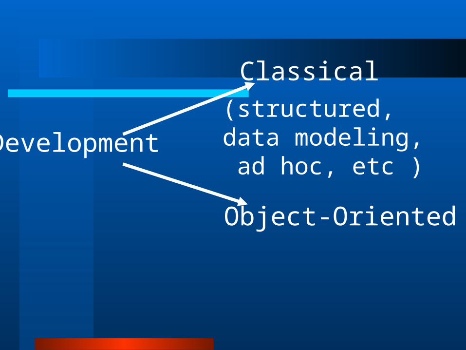
Classical
Object-Oriented
Development(structured, data modeling, ad hoc, etc )

A Student Guide Object-Oriented A Student Guide Object-Oriented DevelopmentDevelopment
Carol Britton & Jill Doake

Course AimCourse Aim
To look at how a software system is developed using an object orientated
approach
System Life Cycle – Why?System Life Cycle – Why?
Need an agreed framework for the development– Identify milestones– Structure activities– Monitoring deliverables
System Life Cycle – Why?System Life Cycle – Why?
Advantages of agreed framework– An overall picture of the development
process– A basis for development – Consistency in approach – Ensures quality
• Structure for planning, monitoring and controlling the development process
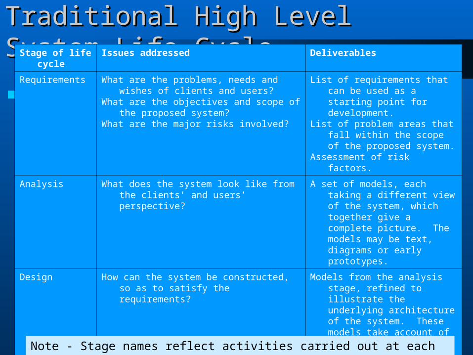
Traditional High Level System Life Cycle Traditional High Level System Life Cycle Stage of life cycle Issues addressed Deliverables
Requirements What are the problems, needs and wishes of clients and users?
What are the objectives and scope of the proposed system?
What are the major risks involved?
List of requirements that can be used as a starting point for development.
List of problem areas that fall within the scope of the proposed system.
Assessment of risk factors.
Analysis What does the system look like from the clients’ and users’ perspective?
A set of models, each taking a different view of the system, which together give a complete picture. The models may be text, diagrams or early prototypes.
Design How can the system be constructed, so as to satisfy the requirements?
Models from the analysis stage, refined to illustrate the underlying architecture of the system. These models take account of technological considerations and constraints arising from the implementation environment.
Implementation How can the models produced be translated into code?
A fully tested suite of programs.
Installation What is needed to support clients and users and ensure that they can use the new system effectively?
User manual, technical documentation, user training.
Note - Stage names reflect activities carried out at each stage
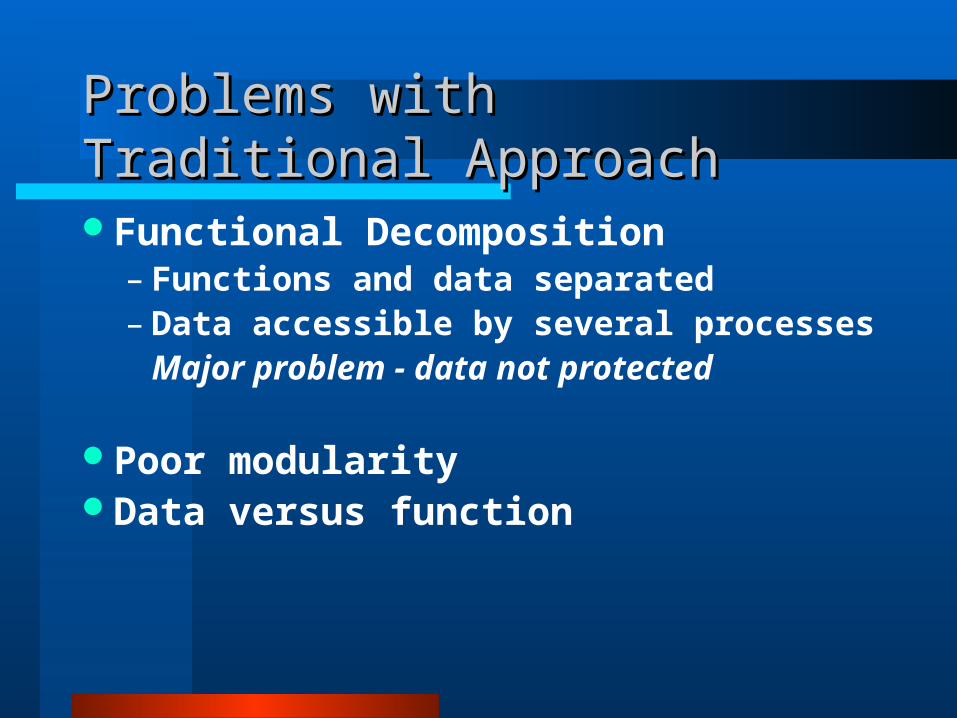
Problems with Traditional ApproachProblems with Traditional Approach
Functional Decomposition– Functions and data separated– Data accessible by several processes
Major problem - data not protected
Poor modularityData versus function
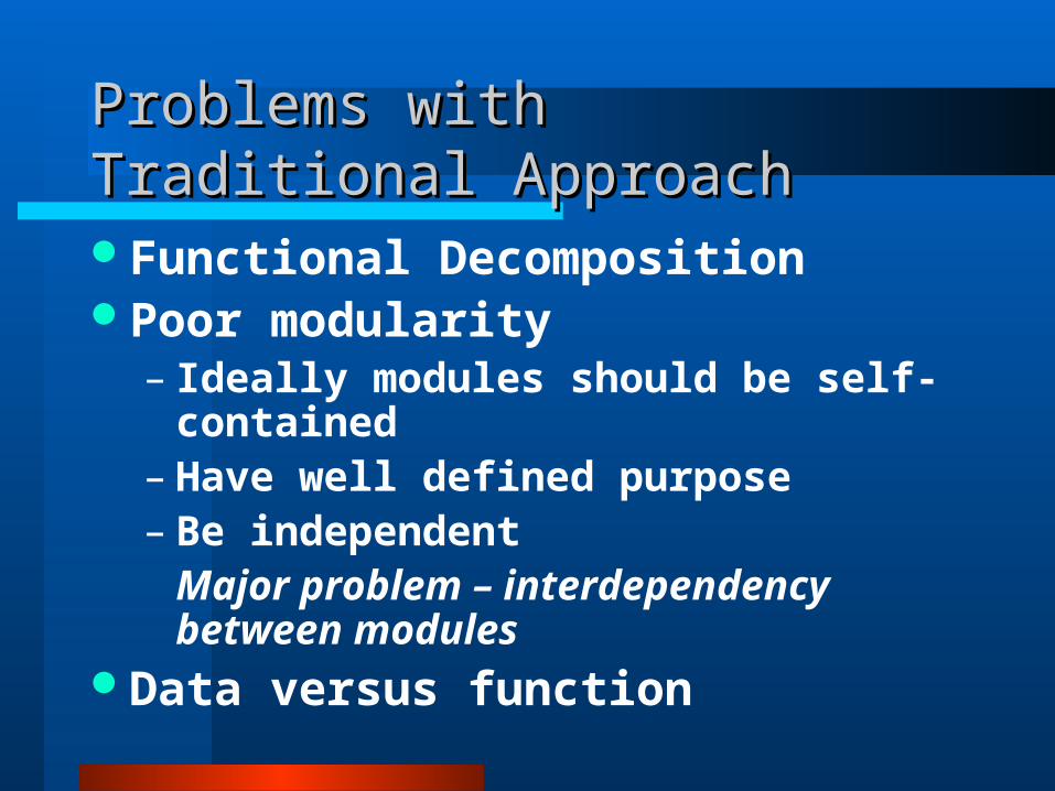
Problems with Traditional ApproachProblems with Traditional Approach
Functional DecompositionPoor modularity
– Ideally modules should be self-contained
– Have well defined purpose– Be independent
Major problem – interdependency between modules
Data versus function

Problems with Traditional ApproachProblems with Traditional Approach
Functional DecompositionPoor modularityData versus function
– System functionality is more likely to change than the data
– Over time the functionality is more unstable than the data

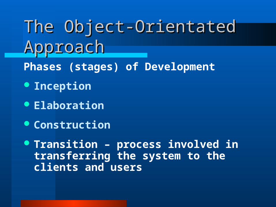
The Object-Orientated ApproachThe Object-Orientated Approach
Phases (stages) of Development
Inception Elaboration Construction Transition
These indicate the state of the system at each phase NOT the activities involved at
that point in development

The Object-Orientated ApproachThe Object-Orientated Approach
Phases (stages) of Development
Inception – the initial work required to set up and agree terms for the project.
Includes establishing the business case
– Feasibility
– Basic risk assessment
– Scope of the system to be delivered

The Object-Orientated ApproachThe Object-Orientated Approach
Phases (stages) of Development
Inception
Elaboration – deals with putting the basic architecture of the system in place
– All main project risks are identified
Construction
Transition

The Object-Orientated ApproachThe Object-Orientated Approach
Phases (stages) of Development
Inception
Elaboration
Construction – involves bulk of work on building the system
– Ends with beta-release of system
Transition
The Object-Orientated ApproachThe Object-Orientated Approach
Phases (stages) of Development
Inception
Elaboration
Construction
Transition – process involved in transferring the system to the clients and users

WorkflowsWorkflows
The activities implied by the stages in a traditional structured modelling approach are referred to as Workflows in the object-orientated approach
Workflows -– Requirements– Analysis– Design– Implementation– Testing

Workflows - activitiesWorkflows - activities
Inception
Elaboration
Construction
Transition
Requirements
Analysis
Design
Implementation
PHASES WORKFLOWS

The Object-Orientated ApproachThe Object-Orientated Approach
Iterative Process - Workflows may be carried out during
any phase of developmentIn each phase a range of workflows
(activities) may be carried out several times before moving on to the next phase
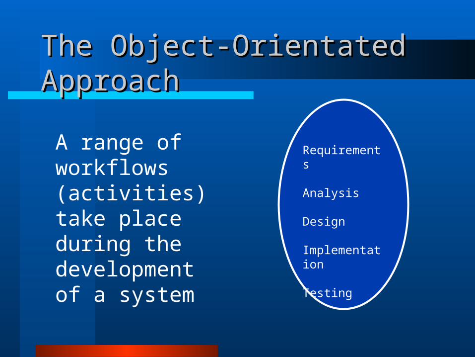
The Object-Orientated ApproachThe Object-Orientated Approach
A range of workflows (activities) take place during the development of a system
Requirements
Analysis
Design
Implementation
Testing

The Object-Orientated ApproachThe Object-Orientated ApproachI n c e p t i o n
E l a b o r a t i o n
C o n s t r u c t i o n
T r a n s i t i o n
An iterative process.
The ellipses represent iterations of workflows (requirements, analysis, design, implementation, testing)

A seamless Development ProcessPhases less distinct than in a
structured approachDifficult to say when one phase ends
and another beginsDriven by a single unifying idea – the
object
The Object-Orientated ApproachThe Object-Orientated Approach

The ObjectThe Object
Basic building blockObjects in the real world translate
into objects in the software system– Physical (customers, products)– Conceptual (orders, reservations– Organisation (companies, departments)– Implementation (GUI Windows)

The foundation of all development work is the object
No new system models introduced at different stages
Early models developed and refined through the development process
An iterative design process
The Object-Orientated ApproachThe Object-Orientated Approach

ModellingModelling
To capture the whole of a system we need to view it from different aspects
Each diagram provides some but not all of the information – abstraction
Each model is an abstraction of the complete system
System is broken down into small workable chunks - decomposition

Unified Modelling Language - UMLUnified Modelling Language - UML
A notation or language for development Not a development method Set of diagrammatic techniques Industry standard for modelling OO
systems UML Creators – Ivar Jacobson, Grady
Booch, James Rumbaugh

Principal UML ModelsPrincipal UML Models
Model View of the system
Use case How the system interacts with its users.
Class The data elements in the system and the relationships between them.
Interaction (sequence and collaboration)
How a use case affects all the objects that are involved in it.
State How the different objects of a single class behave through all the use cases in which the class in involved.
Activity The sequence of activities that make up a process.
Component The different components of the system and the dependencies between them.
Deployment The software and hardware elements of the system and the physical relationships between them.
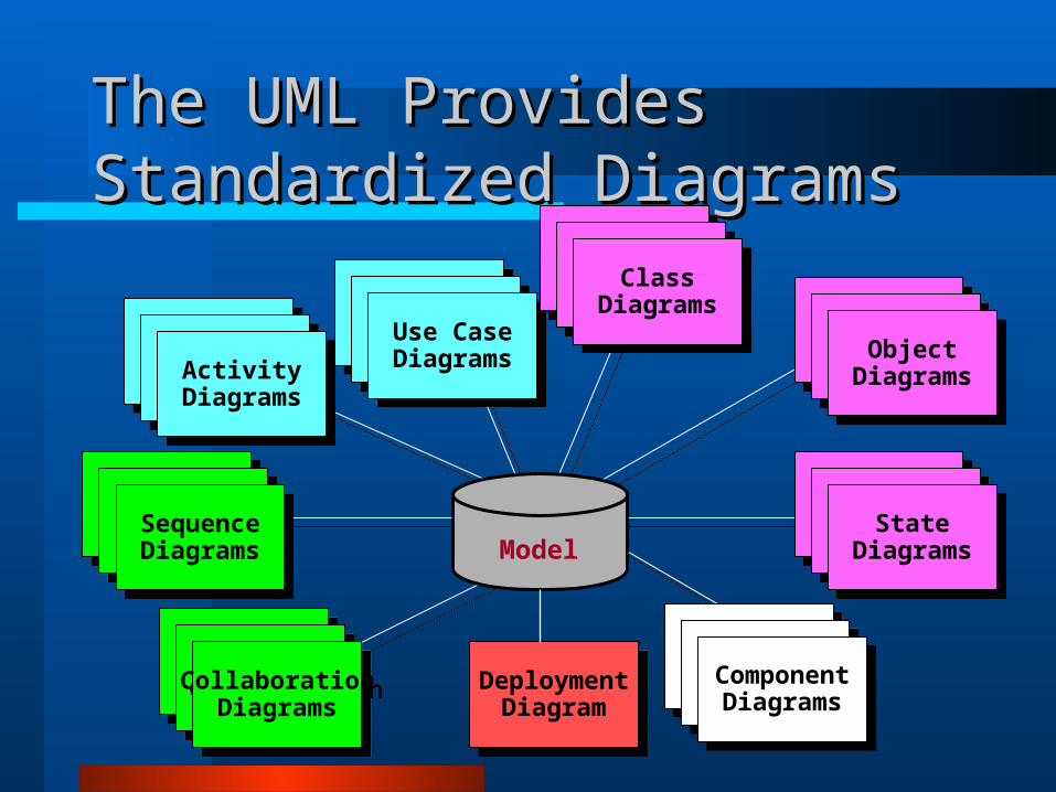
The UML Provides Standardized The UML Provides Standardized DiagramsDiagrams
DeploymentDiagram
DeploymentDiagram
Use CaseDiagrams
Use CaseDiagramsUse Case
Diagrams
Use CaseDiagramsUse Case
Diagrams
Use CaseDiagrams
ScenarioDiagrams
ScenarioDiagramsScenario
Diagrams
ScenarioDiagramsSequence
Diagrams
SequenceDiagrams
StateDiagrams
StateDiagramsState
Diagrams
StateDiagramsState
Diagrams
StateDiagrams
ComponentDiagrams
ComponentDiagramsComponent
Diagrams
ComponentDiagramsComponentDiagrams
ComponentDiagrams
Model
StateDiagrams
StateDiagramsState
Diagrams
StateDiagramsObject
Diagrams
ObjectDiagrams
ScenarioDiagrams
ScenarioDiagramsScenario
Diagrams
ScenarioDiagramsCollaboration
Diagrams
CollaborationDiagrams
Use CaseDiagrams
Use CaseDiagramsUse Case
Diagrams
Use CaseDiagramsActivity
Diagrams
ActivityDiagrams
StateDiagrams
StateDiagramsState
Diagrams
StateDiagramsClass
Diagrams
ClassDiagrams

UUnified nified MModeling odeling LLanguage anguage ((UML)UML)
“A graphical language for visualizing, specifying, constructing, and documenting the artifacts of a software intensive system.” [Booch]

UML in One SentenceUML in One Sentence
The UML is a graphical language forvisualizingspecifyingconstructingdocumenting
artifacts of a software-intensive system.

VisualizingVisualizing
explicit model facilitates communicationsome structures transcend (pass or more)
what can be represented in programming language
each symbol has well-defined semantics behind it

SpecifyingSpecifying
The UML addresses the specification of all important analysis, design, and implementation decisions.

ConstructingConstructing
Forward engineering: generation of code from model into programming language
Reverse engineering: reconstructing model from implementation
Round-trip engineering: going both ways
UML and BlueprintsUML and Blueprints
The UML provides a standard way to write a system’s “blueprints” to account for
conceptual things (business processes, system functions)
concrete things (C++/Java classes, database schemas, reusable software components)
In UML, we have a state diagram for dynamic behavior. The state diagram shows:
-State-Transition-Event-Condition-Action

Construct Description Syntax
class a description of a set of objects that share the same attributes, operations, methods, relationships and semantics.
interface a named set of operations that characterize the behavior of an element.
component a modular, replaceable and significant part of a system that packages implementation and exposes a set of interfaces.
node a run-time physical object that represents a computational resource.
«interface»
Structural Modeling: Core ElementsStructural Modeling: Core Elements
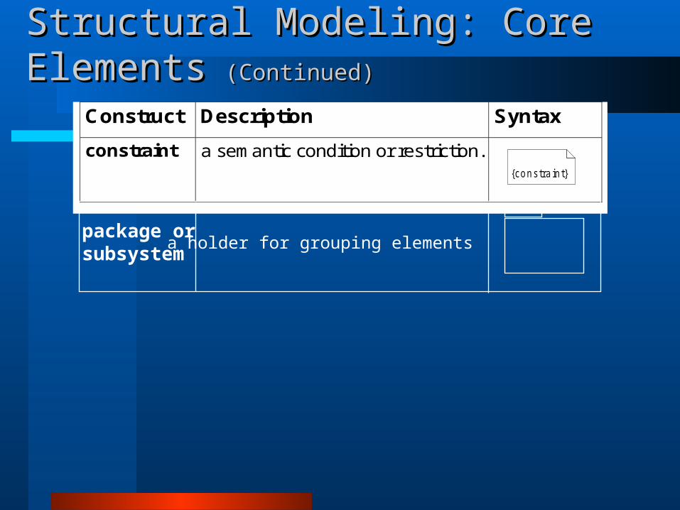
Structural Modeling: Core ElementsStructural Modeling: Core Elements (Continued)(Continued)
Construct Description Syntax
constraint a semantic condition or restriction.
{constra in t}
package orsubsystem
a holder for grouping elements

Construct Description Syntax
association a relationship between two or more classifiers that involves connections among their instances.
aggregation A special form of association that specifies a whole-part relationship between the aggregate (whole) and the component part.
generalization a taxonomic relationship between a more general and a more specific element.
dependency a relationship between two modeling elements, in which a change to one modeling element (the independent element) will affect the other modeling element (the dependent element).
Structural Modeling: Core RelationshipsStructural Modeling: Core Relationships
(open arrow)
Composition

Construct Description Syntax
realization a relationship between a specification and its implementation.
Structural Modeling: Core Structural Modeling: Core Relationships Relationships (Continued)(Continued)
(closed arrow)
Realization relationship connects a model element such as a class, to another model element, such as an interface that supplies its behavioral specification but not its structure or implementation. The client must support ( by inheritance or by direct declaration) at least all the operations that the supplier has.


Class Diagram ConceptsClass Diagram Concepts
A static model that shows the classes and relationships among classes that remain constant in the system over time
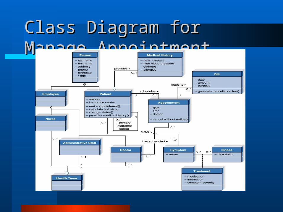
Class Diagram for Manage Class Diagram for Manage AppointmentAppointment

HW1: due date one week from today:Model the following using a class diagram:Your company writes student and course data management software for universities. You are writing a data management package for a university with several campuses. Employees in the administration office of each campus has to enter several student and class input parameters; these will be stored in a central database in the main campus. CORBA has been chosen to send this data. There will be two kinds of data: per student data, and per course data. For each student, the administration employee will enter a social security number, a 3 line home address, and the current semester’s grades (the student will have taken at least one class, and no more than 5 classes). If the student is also a university employee, the administration employee will enter the student’s salary. For each course, the administration employee will enter the instructor’s name, the time of day the course meets, the days of the week the course meets, the date and time of the final exam, and the number of hours of the course. The administration employee will also enter a student name and social security number for each student in the course.The central database software will provide values in return. For each student, the student’s new GPA (based on existing plus new classes) will be returned, along with total number of courses the student has taken at the university. For each course, the central database software will provide the total number of courses the instructor is teaching this semester. If the final exam time entered does not match that stored in the central database, then the final exam time variable will be corrected

Further readingFurther reading
Bennett, S., McRobb, S. and Farmer, R. Object-Oriented Systems Analysis and Design Using UML, 2nd Ed, London: McGraw-Hill, 2002.
Brown, D. Object-Oriented Analysis: objects in plain English, New York: John Wiley, 1997.
Fowler, M. UML Distilled: a brief guide to the standard object modeling language, 2nd Ed, Reading Massachusetts: Addison-Wesley, 2000.
Jacobson, I. Object-Oriented Software Engineering: A Use Case Driven Approach, Wokingham, England: Addison-Wesley, 1992.
Larman, C. Applying UML and patterns: an introduction to object-oriented analysis and design, New Jersey: Prentice Hall, 1998.
Stevens, P., with Pooley, R. Using UML. Software Engineering with Objects and Components Updated edition, Harlow: Addison-Wesley, 2000.