obfuscation of transmission fingerprints...
TRANSCRIPT

Obfuscation of Transmission Fingerprintsfor Secure Wireless Communications
Item Type text; Electronic Dissertation
Authors Rahbari, Hanif
Publisher The University of Arizona.
Rights Copyright © is held by the author. Digital access to this materialis made possible by the University Libraries, University of Arizona.Further transmission, reproduction or presentation (such aspublic display or performance) of protected items is prohibitedexcept with permission of the author.
Download date 27/06/2018 08:37:35
Link to Item http://hdl.handle.net/10150/612371

OBFUSCATION OF TRANSMISSION FINGERPRINTS FORSECURE WIRELESS COMMUNICATIONS
by
Hanif Rahbari
A Dissertation Submitted to the Faculty of the
DEPARTMENT OF ELECTRICAL AND COMPUTER ENGINEERING
In Partial Fulfillment of the RequirementsFor the Degree of
DOCTOR OF PHILOSOPHY
In the Graduate College
THE UNIVERSITY OF ARIZONA
2 0 1 6

2
THE UNIVERSITY OF ARIZONAGRADUATE COLLEGE
As members of the Dissertation Committee, we certify that we have read the dis-sertation prepared by Hanif Rahbarientitled Obfuscation of Transmission Fingerprints for Secure Wireless Communica-tionsand recommend that it be accepted as fulfilling the dissertation requirement for theDegree of Doctor of Philosophy.
Date: 18 December 2015Marwan Krunz
Date: 18 December 2015Loukas Lazos
Date: 18 December 2015Ming Li
Final approval and acceptance of this dissertation is contingent upon the candidate’ssubmission of the final copies of the dissertation to the Graduate College.I hereby certify that I have read this dissertation prepared under my direction andrecommend that it be accepted as fulfilling the dissertation requirement.
Date: 18 December 2015Dissertation Director: Marwan Krunz

3
STATEMENT BY AUTHOR
This dissertation has been submitted in partial fulfillment of requirements for anadvanced degree at the University of Arizona and is deposited in the UniversityLibrary to be made available to borrowers under rules of the Library.
Brief quotations from this dissertation are allowable without special permission,provided that accurate acknowledgment of source is made. Requests for permissionfor extended quotation from or reproduction of this manuscript in whole or in partmay be granted by the head of the major department or the Dean of the GraduateCollege when in his or her judgment the proposed use of the material is in theinterests of scholarship. In all other instances, however, permission must be obtainedfrom the author.
SIGNED: Hanif Rahbari

4
ACKNOWLEDGEMENTS
There are a number of people I would like to express my gratitude to for their helpand support during my time in graduate school.
First of all, I would like to express my deepest gratitude to my advisor, ProfessorMarwan Krunz, for his patience and all the help, care, advice, supports and encour-agements he gave to me during the past five years. Because of him, my graduateexperience has been the one that I will cherish forever. I am fortunate to have himas my advisor who taught me how to think out of the box and conduct meaningfulresearch. Through his professional experience, he has broaden my understanding ofthe research world and about where to explore and what is necessary to get there.This dissertation would have been impossible without his guidance. Thank you.
I would like to thank Professor Loukas Lazos for his supports and collaborations,and all his insightful suggestions and discussions that made this dissertation better. Ialso would like to thank Professor Ming Li for his support and important discussionsthat helped me improve this dissertation, and Professors Tamal Bose and Wei HuaLin for their suggestions.
I would like to thank all my former and current labmates in the wireless net-working group for their help and invaluable friendship. I wish to give special thanksto Rashad Eletreby for his collaborations on part of this work, and to Dr. DiepNguyen, Dr. Mohammad J. Abdel-Rahman, Wessam Afifi, and Peyman Siyary fortheir valuable discussions and generous helps. I would also thank Tami Whelan forhandling all the paperwork and giving various forms of support during my graduatestudy.
Last but not least, I would like to thank my parents and my dear wife GhazalDehghani for supporting and encouraging me throughout my Ph.D. study. Theirlove and care gave me strength to overcome difficulties throughout this endeavor.

5
DEDICATION
This dissertation is dedicated to my wife Ghazal Dehghani, who has been proud
and supportive of my work with a lot of patience and who has shared the many
uncertainties, challenges and sacrifices for completing this dissertation. I am truly
thankful for having you in my life. This work is also dedicated to my parents: my
mother, M. Zahabioun, who endured the six years I have been studying abroad and
who supported me throughout her life by every means, specially by providing
excellent educational environment for me; and my father, A. Rahbari, who has been
my role-model for honesty, persistence, and personal sacrifices, and who instilled in
me the inspiration to do works that benefit the people. I am truly blessed for being
your son.

6
TABLE OF CONTENTS
LIST OF FIGURES . . . . . . . . . . . . . . . . . . . . . . . . . . . . . . . . 9
LIST OF TABLES . . . . . . . . . . . . . . . . . . . . . . . . . . . . . . . . . 12
ABSTRACT . . . . . . . . . . . . . . . . . . . . . . . . . . . . . . . . . . . . 13
CHAPTER 1 Introduction . . . . . . . . . . . . . . . . . . . . . . . . . . . . 161.1 SCI-based Attacks in Wireless Networks . . . . . . . . . . . . . . . . 18
1.1.1 Passive Attacks . . . . . . . . . . . . . . . . . . . . . . . . . . 191.1.2 Active Attacks . . . . . . . . . . . . . . . . . . . . . . . . . . 22
1.2 Main Contributions . . . . . . . . . . . . . . . . . . . . . . . . . . . . 241.2.1 Design and Implementation of an FO Estimation Attack . . . 241.2.2 Friendly Jamming in Multi-link/hop Networks . . . . . . . . . 261.2.3 Frame Encryption and Modulation Obfuscation . . . . . . . . 271.2.4 Exploiting Frame Preamble to Modulate User-Information Bits 28
1.3 Dissertation Organization . . . . . . . . . . . . . . . . . . . . . . . . 29
CHAPTER 2 Background . . . . . . . . . . . . . . . . . . . . . . . . . . . . 302.1 Preamble Structure in OFDM-based 802.11 Systems . . . . . . . . . . 30
2.1.1 STF Functions . . . . . . . . . . . . . . . . . . . . . . . . . . 312.1.2 LTF Functions . . . . . . . . . . . . . . . . . . . . . . . . . . 34
2.2 Preamble Structure in 802.11b Systems . . . . . . . . . . . . . . . . . 34
CHAPTER 3 Jamming of Frequency Offset Estimation in OFDM Systems . 363.1 Introduction . . . . . . . . . . . . . . . . . . . . . . . . . . . . . . . . 36
3.1.1 Existing Attacks Against FO Estimation . . . . . . . . . . . . 383.1.2 Main Contributions and Chapter Organization . . . . . . . . . 39
3.2 FO in OFDM Systems . . . . . . . . . . . . . . . . . . . . . . . . . . 403.3 Model and Assumptions . . . . . . . . . . . . . . . . . . . . . . . . . 433.4 Proposed Frequency Offset Estimation Attack . . . . . . . . . . . . . 44
3.4.1 Phase 1: Adaptive Fast Frame Detection . . . . . . . . . . . . 443.4.2 Phase 2: Preamble Jamming . . . . . . . . . . . . . . . . . . . 443.4.3 Effects of LTSs on FO and Channel Estimation . . . . . . . . 523.4.4 Optimal Jamming Strategy . . . . . . . . . . . . . . . . . . . 53
3.5 Discussion . . . . . . . . . . . . . . . . . . . . . . . . . . . . . . . . . 563.6 Performance Evaluation . . . . . . . . . . . . . . . . . . . . . . . . . 57
TABLE OF CONTENTS – Continued
7
3.6.1 Simulations . . . . . . . . . . . . . . . . . . . . . . . . . . . . 583.6.2 USRP Experiments . . . . . . . . . . . . . . . . . . . . . . . . 633.6.3 Comparison to Existing Jamming Attacks . . . . . . . . . . . 67
3.7 Defense Strategies . . . . . . . . . . . . . . . . . . . . . . . . . . . . . 683.8 Summary . . . . . . . . . . . . . . . . . . . . . . . . . . . . . . . . . 70
CHAPTER 4 Friendly Jamming in Multi-link Scenarios . . . . . . . . . . . . 724.1 Introduction . . . . . . . . . . . . . . . . . . . . . . . . . . . . . . . . 72
4.1.1 Existing FJ-based Schemes for Multi-link Scenarios . . . . . . 724.1.2 Main Contributions and Chapter Organization . . . . . . . . . 74
4.2 Distributed MIMO for FJ Nullification . . . . . . . . . . . . . . . . . 764.2.1 Synchronization of FJ Devices . . . . . . . . . . . . . . . . . . 764.2.2 Nullification of FJ Signals . . . . . . . . . . . . . . . . . . . . 77
4.3 PHY-layer Security for Multi-link Networks . . . . . . . . . . . . . . 784.3.1 Network Model and Problem Formulation . . . . . . . . . . . 784.3.2 Solution Based on Condensation Techniques . . . . . . . . . . 81
4.4 Secrecy-aware Routing Problem . . . . . . . . . . . . . . . . . . . . . 824.5 Simulation Results . . . . . . . . . . . . . . . . . . . . . . . . . . . . 83
4.5.1 Per-link P2P Scenarios . . . . . . . . . . . . . . . . . . . . . . 834.5.2 Per-link Multihop (Routing) Scenarios . . . . . . . . . . . . . 864.5.3 Network-wide Scenarios . . . . . . . . . . . . . . . . . . . . . 87
4.6 Summary . . . . . . . . . . . . . . . . . . . . . . . . . . . . . . . . . 87
CHAPTER 5 Friendly CryptoJam . . . . . . . . . . . . . . . . . . . . . . . . 895.1 Introduction . . . . . . . . . . . . . . . . . . . . . . . . . . . . . . . . 89
5.1.1 Existing Countermeasures for Hiding SCI . . . . . . . . . . . . 895.1.2 Overview of Friendly CryptoJam . . . . . . . . . . . . . . . . 94
5.2 Background – PHY-layer Attributes . . . . . . . . . . . . . . . . . . . 955.3 System Model . . . . . . . . . . . . . . . . . . . . . . . . . . . . . . . 975.4 Modulation Unification . . . . . . . . . . . . . . . . . . . . . . . . . . 98
5.4.1 Uncoded Modulation Unification . . . . . . . . . . . . . . . . 995.4.2 Residual FO Estimation Error . . . . . . . . . . . . . . . . . . 1035.4.3 Untraceable Trellis-Coded Modulation Unification . . . . . . . 106
5.5 Preamble-based PHY-Layer Identifier . . . . . . . . . . . . . . . . . . 1125.5.1 Embedding the ID . . . . . . . . . . . . . . . . . . . . . . . . 1145.5.2 Implication on PHY-layer Functions and Practical Issues . . . 1165.5.3 Encryption of Header Fields . . . . . . . . . . . . . . . . . . . 118
5.6 Performance Evaluation . . . . . . . . . . . . . . . . . . . . . . . . . 1195.6.1 Modulation Scheme Indistinguishability . . . . . . . . . . . . . 121
TABLE OF CONTENTS – Continued
8
5.6.2 System Emulations . . . . . . . . . . . . . . . . . . . . . . . . 1225.6.3 USRP Experiments . . . . . . . . . . . . . . . . . . . . . . . . 126
5.7 Summary . . . . . . . . . . . . . . . . . . . . . . . . . . . . . . . . . 129
CHAPTER 6 Exploiting Frame Preamble to Modulate User-Information Bitsin OFDM-based 802.11 Systems . . . . . . . . . . . . . . . . . . . . . . . . 1306.1 Introduction . . . . . . . . . . . . . . . . . . . . . . . . . . . . . . . . 1306.2 Applications of P-modulation . . . . . . . . . . . . . . . . . . . . . . 1326.3 Preliminaries – STF Requirements . . . . . . . . . . . . . . . . . . . 134
6.3.1 STF Functions . . . . . . . . . . . . . . . . . . . . . . . . . . 1356.3.2 STF Requirements . . . . . . . . . . . . . . . . . . . . . . . . 136
6.4 Proposed Preamble-Modulation Scheme . . . . . . . . . . . . . . . . . 1386.4.1 Sequence Modulation . . . . . . . . . . . . . . . . . . . . . . . 1396.4.2 Sequence Demodulation . . . . . . . . . . . . . . . . . . . . . 1436.4.3 Noncompliant but Possible STF Waveforms . . . . . . . . . . 147
6.5 Effects of Channel/Device Impairments on P-modulation . . . . . . . 1486.5.1 Tx-Rx Channel Coefficients . . . . . . . . . . . . . . . . . . . 1486.5.2 Frame Detection Accuracy . . . . . . . . . . . . . . . . . . . . 1496.5.3 Frequency Offset Estimation Error . . . . . . . . . . . . . . . 151
6.6 MIMO and 802.11n/ac Systems . . . . . . . . . . . . . . . . . . . . . 1526.7 Performance Evaluation . . . . . . . . . . . . . . . . . . . . . . . . . 152
6.7.1 Simulations . . . . . . . . . . . . . . . . . . . . . . . . . . . . 1536.7.2 USRP Experiments . . . . . . . . . . . . . . . . . . . . . . . . 156
6.8 Summary . . . . . . . . . . . . . . . . . . . . . . . . . . . . . . . . . 158
CHAPTER 7 CONCLUSIONS AND FUTURE RESEARCH DIRECTIONS 1597.1 Conclusions . . . . . . . . . . . . . . . . . . . . . . . . . . . . . . . . 1597.2 Future Research Directions . . . . . . . . . . . . . . . . . . . . . . . . 161
REFERENCES . . . . . . . . . . . . . . . . . . . . . . . . . . . . . . . . . . . 163
9
LIST OF FIGURES
1.1 Encryption of a protocol’s payload at different layers of the protocol
stack . . . . . . . . . . . . . . . . . . . . . . . . . . . . . . . . . . . . 17
1.2 Typical 802.11 frame preamble, PHY header, and MAC header. . . . 18
1.3 Example of website identification using uplink/downlink traffic volume 21
2.1 Preamble structure in 802.11a/g/n/ac systems . . . . . . . . . . . . . 31
2.2 Example of phase offset averaged over L = 4 si terms. . . . . . . . . . 34
3.1 Effect of uncompensated FO on an image over a noiseless channel . . 37
3.2 ICI as a result of uncorrected FO in OFDM systems. . . . . . . . . . 41
3.3 Phase and frequency offsets as observed during the STSs. . . . . . . 45
3.4 Arrangement of the samples according to the chaining and pairing rules 50
3.5 Example of subcarrier shift. . . . . . . . . . . . . . . . . . . . . . . . 53
3.6 Amount of subcarrier shift based on Alice’s and Eve’s signals. . . . . 54
3.7 Optimal |∆feb−∆fab| and resulting subcarrier shift for different SJR
values . . . . . . . . . . . . . . . . . . . . . . . . . . . . . . . . . . . 55
3.8 Performance of different variants of frame detection vs. SNR . . . . . 59
3.9 Performance of different variants of the FO attack and of random
FO jamming under different noise levels, Deb and SJR values, and
modulation schemes . . . . . . . . . . . . . . . . . . . . . . . . . . . . 60
3.10 USRP results: Performance of the FO attack in LOS scenario. . . . . 64
3.11 USRP results: Performance of the FO attack in the NLOS scenario. . 66
3.12 Applying the FO attack on a sequence of frames belonging to an image. 69
4.1 Example of possible placements of FJ devices . . . . . . . . . . . . . 75
4.2 Network topology for the case of five P2P links. . . . . . . . . . . . . 84

10
4.3 Total jamming power vs. number of links for the per-link P2P scenario 84
4.4 Outcome of the proposed per-link scheme for the one-link case. . . . . 85
4.5 Jamming power vs. approximation (iteration) index . . . . . . . . . . 85
4.6 Power consumption vs. number of potential eavesdropping locations. 86
4.7 Network topology for routing simulations. . . . . . . . . . . . . . . . 86
4.8 Power consumption in network-wide scheme vs. per-link scheme. . . . 88
5.1 Example of cross-correlation attack . . . . . . . . . . . . . . . . . . . 92
5.2 Example of Combining QPSK-modulated and BPSK-modulated signals 93
5.3 Example of using Friendly CryptoJam to hide the header fields and
the modulation scheme. . . . . . . . . . . . . . . . . . . . . . . . . . 96
5.4 Transmission chain at Alice under FCJ . . . . . . . . . . . . . . . . . 98
5.5 Optimal mapping from QPSK to 16-QAM . . . . . . . . . . . . . . . 102
5.6 Optimal mapping from 16-QAM to 64-QAM . . . . . . . . . . . . . . 103
5.7 Example of uneven impact of phase offset on symbols with differ-
ent amplitudes when QPSK symbols are mapped to four 64-QAM
symbols. . . . . . . . . . . . . . . . . . . . . . . . . . . . . . . . . . 104
5.8 Impact of phase offset on differentMi andMM . . . . . . . . . . . . 105
5.9 Minimal two-state TCM scheme . . . . . . . . . . . . . . . . . . . . . 108
5.10 Minimal four-state TCM scheme . . . . . . . . . . . . . . . . . . . . . 109
5.11 R(., n) computed over a frame. . . . . . . . . . . . . . . . . . . . . . 115
5.12 Empirical probability density functions of pairs of successive modu-
lated symbols usingMM = 16-QAM and differentMi’s . . . . . . . . 121
5.13 Impact of embedded ID on frame detection (emulations). . . . . . . . 122
5.14 Digit-error rate in ID detection vs. SNR (emulations). . . . . . . . . 122
5.15 BER vs. SNR of modulation unification at Bob when MM = 16-
QAM (emulations) . . . . . . . . . . . . . . . . . . . . . . . . . . . . 124
5.16 BER vs. SNR of modulation unification at Bob when MM = 64-
QAM (emulations) . . . . . . . . . . . . . . . . . . . . . . . . . . . . 125

11
5.17 Empirical cumulative distribution function of BER (USRP results). . 127
6.1 Preamble structure and subcarriers in 802.11a. si refers to the ith
subcarrier in the STF, i ∈ {−6, . . . , 6}/{0}. . . . . . . . . . . . . . . 135
6.2 Amplitudes of the four STFs generated using the patterns in Ta-
ble 6.2. (Only one STS is shown.) . . . . . . . . . . . . . . . . . . . 139
6.3 Phases of the four STFs generated using the patterns in Table 6.2.
(Only one STS is shown.) . . . . . . . . . . . . . . . . . . . . . . . . 140
6.4 99 phase differences among 12 × 9 = 108 symbols extracted from 9
STSs. The Tx uses 16-DPSK and the Rx detects ν = 3π/16 using
MMSE estimator (γ = 3dB). . . . . . . . . . . . . . . . . . . . . . . 144
6.5 BER of BPSK and P-modulation with different Q-DPSK andM-PSK
schemes vs. γ. . . . . . . . . . . . . . . . . . . . . . . . . . . . . . . . 146
6.6 Linear channel phase changes across OFDM subcarriers (tE = −4,N = 64, and Tx power = −25 dBm). . . . . . . . . . . . . . . . . . . 150
6.7 BER vs. γ (simulations). For P-mod. (FD-DPSK) and P-mod.
(PSK), only the value of Q and M applies, respectively. . . . . . . . . 153
6.8 Robustness of P-modulation to channel impairments compared to
BPSK (simulations). . . . . . . . . . . . . . . . . . . . . . . . . . . . 155
6.9 Performance of P-modulation vs. γ when Q = 16, M = 16, and
δf ≈ 0 (USRP experiments). . . . . . . . . . . . . . . . . . . . . . . . 157
6.10 Performance of P-modulation vs. γ when Q = 16 and M = 16, and
under imperfect FO estimation (USRP experiments). . . . . . . . . . 157

12
LIST OF TABLES
2.1 DSSS signal spreading based on an 11-chip Barker sequence. . . . . . 35
3.1 Average value of mV −1 in the chaining rule for different SNR levels. 59
3.2 Distances between Alice, Bob, and Eve for two different scenarios. . . 63
4.1 Minimum-energy path cost (per-link scheme vs. fixed-placement
schemes). . . . . . . . . . . . . . . . . . . . . . . . . . . . . . . . . . 87
5.1 Parameters of the optimal mapping from BPSK and QPSK to 16-QAM.101
5.2 Parameters of the optimal mapping from 802.11a modulation schemes
to 64-QAM. . . . . . . . . . . . . . . . . . . . . . . . . . . . . . . . . 101
5.3 Example of the concatenation of two Barker sequences to embed ID . 116
6.1 Sequence of QPSK-modulated symbols used to generate STF in
802.11a/g [1]. |s−6| = |s−5| = . . . = |s6| =√2. This sequence
is then multiplied by√
13/6 to normalize the average power of the
resulting symbols. . . . . . . . . . . . . . . . . . . . . . . . . . . . . . 137
6.2 Dependency patterns among all possible combinations of QPSK-
modulated symbols in S that satisfy the STF requirements. The
IEEE standard uses the dependency pattern Θ3 and ϕ = 0 when
s−6 = 1 + j. . . . . . . . . . . . . . . . . . . . . . . . . . . . . . . . . 138
13
ABSTRACT
Our world of people and objects is on the verge of transforming to a world of
highly-interconnected wireless devices. Incredible advances in wireless communica-
tions, hardware design, and power storage have facilitated hasty spread of wireless
technologies in human life. In this new world, individuals are often identified and
reached via one or multiple wireless devices that they always carry (e.g., smart-
phones, smart wearable, implantable medical devices, etc.), and their biometrics
identities are replaced by their digital fingerprints. In near future, vehicles will
be controlled and monitored via wireless monitoring systems and various physical
objects (e.g., home appliance and retail store items) will be connected to the In-
ternet. The list of these changes goes on. Unfortunately, as different aspects of
our lives are being immerged in and dependent to wireless devices and services,
we will become more vulnerable to wireless service/connection interruptions due
to adversarial behavior and our privacy will become more potent to be exposed to
adversaries. An adversary can learn the procedures of a wireless system and ana-
lyze its stages, and accordingly, launch various attacks against the operations of the
system or the privacy of the people. Existing data confidentiality and integrity ser-
vices (e.g., advanced encryption algorithms) have been able to prevent the leakage
of users’ messages. However, in wireless networks, even when upper-layer payloads
are encrypted, the users’ privacy and the operation of a wireless network can be
threatened by the leakage of transmission attributes at the physical (PHY) layer.
Examples of these attributes are payload size, frequency offset (FO), modulation
scheme, and the transmission rate. These attributes can be exploited by an adver-
sary to launch passive or active attacks. A passive attacker may learn about the
interests, sexual orientation, political views, and patentable ideas of the user through
analyzing these features, whereas an active attacker exploits captured attributes to

14
launch selective packet jamming/dropping and disrupt wireless services. These call
for novel privacy preserving techniques beyond encryption.
In this dissertation, we study the vulnerability of current wireless systems to the
leakage of transmission attributes at the PHY layer and propose several schemes
to prevent it. First, we design and experimentally demonstrate with USRPs an
energy-efficient and highly disruptive jamming attack on the FO estimation of an
OFDM system. OFDM is the core multiplexing scheme in many modern wireless
systems (e.g., LTE/5G and 802.11a/n/ac) and is highly susceptible to FO. FO is
the difference in the operating frequencies of two radio oscillators. This estimation
is done by the receiver using the publicly-known frame preamble. We show that the
leakage of FO value via the preamble can facilitate an optimally designed jamming
signal without needing to know the channel between the transmitter and the legiti-
mate receiver. Our results show that the jammer can guarantee a successful attack
even when its power is slightly less than the transmitter’s power. We then propose
four mitigation approaches against the proposed FO attack.
Next, we consider certain transmission attributes that are disclosed via unen-
crypted PHY/MAC headers. Example of these attributes are payload size, trans-
mission rate, and MAC addresses. Beyond unencrypted headers, the adversary can
estimate the frame size and transmission rate through identifying the payload’s
modulation scheme and measuring the transmission time. To prevent the leakage
of these attributes, we propose Friendly CryptoJam scheme, which consists of three
components: First, a modulation-aware encryption scheme to encrypt the headers.
Second, an efficient modulation obfuscation techniques. Specifically, the proposed
modulation obfuscation scheme embeds the modulation symbols of a frame’s pay-
load into the constellation of the highest-order modulation scheme supported by
the system. Together with effective PHY/MAC header encryption at the modu-
lation level, the proposed obfuscation scheme hides the transmission rate, payload
size, and other attributes announced in the headers while avoiding any BER perfor-
15
mance loss. Compared with prior art, Friendly CryptoJam enjoys less complexity
and less susceptibility to FO estimation errors. The third component is a novel
PHY-level identification method. To facilitate PHY/MAC header encryption when
a MAC layer sender identifier cannot be used (e.g., due to MAC address encryp-
tion), we propose two preamble-based sender identification methods, one for OFDM
and one for non-OFDM systems. A sender identifier is special message that can be
embedded in the frame preamble. The extent of the applications of our embedding
scheme goes beyond identifier embedding and include embedding part of the data
frame, the sender’s digital signature, or any meta-data that the sender provides.
Our message embedding method can further be used to mitigate the FO estimation
attack because the jammer can no longer optimize its jamming signal with respect
to a fixed preamble signal. In addition, we considered friendly jamming technique in
a multi-link/hop network to degrade the channels of the eavesdroppers and prevent
successful decoding of the headers, while minimizing the required jamming power
by optimally placing the friendly jamming devices.
16
CHAPTER 1
Introduction
The proliferation of wireless technologies in various aspects of human life has been
phenomenal. By 2015, it is expected that nearly two billion mobile phones and
more than 300 thousand tablets will be sold annually worldwide [2], and that the
WiFi market size will grow from USD 14.8 billion in 2015 to USD 33.6 billion by
2020. Beyond smartphones and laptops, wireless communications and networking
technologies are being used in medical services and devices, vehicle control and
vehicle-to-vehicle communications, border control, just to name a few. As we con-
tinue to depend on such a rapidly expanding wireless ecosystem, we are challenged
with serious threats related to user privacy, data confidentiality, and system avail-
ability. Due to the broadcast nature of the wireless medium, user communications
are exposed to eavesdropping and privacy attacks. Unauthorized parties equipped
with commodity radio hardware can easily eavesdrop on wireless transmissions.
Encryption is the common way for providing message confidentiality and user
privacy. For example, at the application layer, encryption algorithms and proto-
cols, such as HTTPS and SSH, provide message confidentiality. At the transport
and network layers, the corresponding headers and payloads are encrypted using
protocols such as TLS and IPSec. At the data link (MAC) layer, WPA2 is used
for 802.11 frames. 3G/UMTS and 4G LTE cellular systems also support message
confidentiality through encryption.
Although cryptography and encryption can be used at the upper layers to pro-
tect the confidentiality of any protocol data unit (PDU), they are not sufficient to
prevent the leakage of side-channel information (SCI) at the physical (PHY) layer.

17
PHY
Link (MAC)
NetworkIPSec TLS https
WPA2
M
hd
r
WPA2
Figure 1.1: Encryption of a protocol’s payload (shown with shading) at differentlayers of the protocol stack. An upper-layer payload and its header are jointlyconsidered the payload for the next lower-layer.
SCI refers to traffic features such as frame type, frame size/duration, modulation
scheme, and transmission rate at the frame level and packet size distribution, traffic
volume, and inter-packet times at the session level. These features can be deter-
mined by eavesdropping on the PHY-layer frame and collectively create a fingerprint
of the traffic or the user that generates it. In many wireless systems (e.g., WiFi sys-
tems, as standardized by the IEEE 802.11 specifications), parts of the frame (e.g.,
PHY/MAC headers) must be transmitted in the clear for correct protocol operation
and device identification. Specifically, 802.11i/WPA2, the primary security amend-
ment of 802.11, provides confidentiality only for the MAC-layer payload of the data
frames and not for PHY/MAC headers (see Figure 1.1). These unencrypted head-
ers can leak certain types of SCI. For example, the PHY header contains the frame
size/duration and transmission rate/modulation scheme fields. Parameters such as
source and destination MAC addresses, direction of the packet, and packet type
(e.g., a retransmission) are specified in the MAC header (see Figure 1.2).
In addition to header fields, certain wireless transmission attributes and radio-
metric features leak SCI. For example, the modulation scheme used for the frame
payload reveals the packet size and the data rate. In digital communications, a bit
sequence is modulated into symbols before transmission over the air. The number
of possible symbols of a modulation scheme (known as modulation order) relates to

18
Rate SizePreamble … Type … Retry …Source
Address
Receiver
Address…Direction … Duration … Payload
PHY header MAC header
Figure 1.2: Typical 802.11 frame preamble, PHY header, and MAC header.
the number of bits that can be represented by a single symbol. Because of channel
noise, symbols must be sufficiently separated so that the legitimate receiver (Rx)
can distinguish them from one another. Consequently, a more noisy channel can
support fewer bits per symbol, and the transmission of a fixed-size payload can take
different durations under different channel conditions. By measuring the frame du-
ration (in seconds) and detecting the modulation scheme, an adversary can estimate
the size (in bytes) of the frame payload.
Beside SCI, in many wireless standards, such as 802.11, certain management
and control frames are often sent in the clear. Various protocol operations, such as
establishing session keys, adjusting the transmission power, and acknowledging the
successful reception of a packet, rely on the exchange of these frames.
In the following section, we explain how adversaries can exploit SCI of (en-
crypted) wireless traffic to launch various attacks against user privacy and function-
ality of a practical wireless network.
1.1 SCI-based Attacks in Wireless Networks
We classify SCI-enabled attacks into two types: passive and active. Passive attacks
refer to SCI analysis performed by an eavesdropper (Eve) to infer private information
about a user. Active attacks refer to selective jamming of specific packets or parts
of a packet, where “significance” of a packet or a part of it is determined based on
the consequences of jamming that packet or part. The mechanisms for acquiring
and analyzing SCI will be discussed below.

19
1.1.1 Passive Attacks
The privacy of a wireless user can be violated by overhearing and analyzing en-
crypted traffic at the PHY layer. We first explain how users can be identified based
on device-specific features. We then explain how users’ activities can be used to
profile and track them.
Device identification and user tracking– Eve can fingerprint a wireless device or
its user by exploiting device identifiers embedded in unencrypted headers, the de-
vice’s intrinsic characteristics and impairments, or captured SCI. Using a device’s
fingerprint, the adversary can easily track the user’s geographical location or de-
termine his online activity. An example of such tracking was demonstrated in a
software program called, Snoopy [3], which was deployed on a low-altitude flying
drone to track users based on their fingerprints, steal their confidential information,
or launch a man-in-the-middle attack by spoofing already trusted access points.
Snoopy does not require a visual sensor; instead, it uses an antenna to observe WiFi
encrypted communications. The globally unique MAC address at the link layer also
acts as a plaintext device identifier. The case of bomb-proof trash cans in London
a couple of years ago is an example of MAC-address-based tracking. The trash can
suppliers had installed a device in the cans to collect information from smartphones
of people walking in London’s Square Mall, based on the MAC addresses, intending
to study people’s shopping habits and produce targeted advertisements [4].
The seriousness of these privacy attacks has been recently acknowledged by IEEE
and IETF, and accordingly, they formed a new study group to assess the privacy
implications of visible MAC addresses and other link-layer privacy issues [5]. To
prevent MAC-address-enabled user tracking, this group suggested using randomly
generated MAC addresses. Other similar approaches were proposed in [6–8] that
are based on a chain of unpredictable but unencrypted time-rolling identifers (e.g.,
MAC addresses). Although such a radical approach faces several hurdles in the
current systems and can take years to finalize [9], it is not adequate for solving the

20
problem of unencrypted PHY headers and the leakage of SCI.
In fact, background activities of Apps installed on a smart phone/tablet or the
specific implementation of the wireless card driver can be used to construct a finger-
print. For instance, Eve can create a device-specific traffic fingerprint by analysing
the SCI of software programs running for 6 hours in the background of a 3G smart-
phone [10]. This is because more than 70% of a smartphone’s traffic is independent
of user interactions and depends only on installed Apps. In fact, by monitoring 15
minutes worth of traffic, the authors in [10] show that it is possible to identify a
particular device with 90% success rate among 20 devices running different sets of
Apps. Similarly, traffic statistics can characterize an 802.11 device with high proba-
bility [11], or the Apps each individual smartphone user in the vicinity is using [12].
Apart from Apps/user-generated traffic, different wireless card vendors often have
different implementations of the same protocol on their cards, resulting in vendor-
specific inter-frame times, medium access wait (backoff) times, and transmission
times [11]. Together, these parameters constitute a vendor-specific fingerprint of
the device.
Beside traffic statistics, hardware-specific and electromagnetic characteristics of
an RF emitter form a “radiometric” identity of a particular transmitter (Tx). The
analog components in a wireless card (e.g., oscillator, baseband filter, amplifier,
and antenna) exhibit inherent manufacturing impairments that differ from one card
to another. Small variations in these components create distinct artifacts in the
emitted signal (e.g., frequency offset and amplitude clipping). The distortions in
the captured modulation symbols due to hardware impairments can be exploited to
detect a signal’s originating device [13].
User’s activities and browsing interests– An eavesdropper can also exploit SCI to
discern the online activities of a user, his interests, or his search queries [12,14–17].
For example, through captured SCI, Eve can identify not only the website that a
user is browsing, but also the currently active page within a specific website [16].

21
Figure 1.3: Distribution of traces of five websites with respect to uplink/downlinktraffic volume, where each symbol of the same shape and color represents the sameweb page [15].
A typical website is characterized by a nominal uplink/downlink traffic volume and
session duration. These coarse-grain traffic features are sufficient to classify web-
sites [15]. In Figure 1.3, an example of such website identification based on only
uplink/downlink traffic volume is shown. Even within a given website in which
different pages (e.g., company products) are targeted to different users, analyzing
the packets size distribution allows for identifying a specific page. As a result, the
attacker may be able to conclude, for example, the user’s product of interest and
may overwhelm him with many commercial ads.
The leakage of private information is not limited to online browsing. An ad-
versary can determine with 80% accuracy the type of user activity (gaming, video
streaming, Skype, browsing, etc.) by only eavesdropping for 5 seconds on that user’s
WiFi traffic [16]. Differences in the traffic statistics of different applications are of-
ten large enough to distinguish these applications. Further, the adversary can find
out the language used in an encrypted instant messaging application or the user’s
specific actions during an activity, such as posting a status on Facebook or opening
a chat window in Gmail, based on the statistics of the sequence of user-generated
packets. Along the same lines, tracking the traffic of two users can reveal if they are

22
communicating with each other.
The sizes (in bytes) and directionality (uplink/downlink) of a sequence of packets
exchanged between a mobile user and an access point can also reveal what the user
is searching for. Google, Bing, and other search engines offer users suggestions for
a searched phrase. This is known as the auto-suggestion feature. When a user
types the first letter of a keyword, the search engine quickly responds with a list of
suggested words. Typing the second letter updates the list of suggestions, and so
on. The size of the packet that contains the list of suggestions is highly correlated
with the typed letters [18]. Eve can construct a table of different keywords and
associate them with the sizes of per-keystroke suggested lists. She can then match
the sizes of an observed sequence of packets to one of the entries in the table, and
determine the queried word [18]. Even the message length and the language used
in an encrypted instant messaging application can be determined based on packet
sizes only.
1.1.2 Active Attacks
Besides breaching user privacy, captured SCI can be used by malicious attackers
to disrupt communications by selectively jamming wireless transmissions and pre-
venting correct decoding at the receiver (Rx). Jamming includes random attacks,
persistent attacks (barrage jamming), and smart/selective attacks in which only a
certain packets or parts of a particular packet are jammed. In selective (reactive)
jamming, a packet (or part of it) is selected for jamming based on the amount of
disruption caused by not delivering this packet to its intended Rx. For example,
TCP Acknowledgement (ACK) packets are much shorter in duration than TCP
data packets, but are critical for maintaining high TCP throughout by preventing a
significant reduction in the congestion window size. Jamming these packets requires
less energy than jamming a data packet. At the same time, it can deceive the TCP
sender into thinking that the last data packet was not successfully received due to

23
network congestion. Consequently, the sender may unnecessarily reduce its packet
transmission rate and retransmit the last packet, which was already received cor-
rectly. The attacker can identify the TCP ACK by analyzing the sequence of inter-
arrival times and packet sizes. In the case of link-layer ACK packets, the packet
type can be identified by inspecting the unencrypted MAC header (see Figure 1.2).
Unencrypted PHY-layer header fields can be intercepted and used to detect and
jam data packets transmitted at high rates. Wireless devices adapt their transmis-
sion rates based on channel conditions. A good channel prompts the Tx to use
a high-order modulation scheme, hence a high data rate. When a packet is not
successfully received, the Tx attributes that to channel conditions and accordingly
retransmits the packet at a lower rate. This can be exploited by the attacker to
jam only high data-rate packets, prompting the Tx to reduce its rate and waste
communication resources [19].
In addition to the PHY header, the modulation scheme of the PHY-frame pay-
load may disclose the transmission rate. A modulation scheme is usually associated
with two or three data rates of different code rates. For example, in 802.11a, 16-
QAM is used for data rates 24 and 36 Mbps. Hence, by determining the modulation
scheme, it is rather easy for the adversary to guess the data rate. Combining this
rate with the frame length, one can compute the payload size. The frame preamble
can also be exploited to detect the arrival of a packet and launch reactive attacks.
This preamble is a publicly known signal, prepended to the beginning of a frame to
help the Rx detect the frame and estimate various communication parameters (e.g.,
frequency offset, channel response, etc.). Correct decoding of a frame depends on
correct estimation of these parameters. Once a frame is detected, an attacker can
jam a vulnerable part of the preamble to disrupt the parameter estimation functions
at the Rx [20]. We will discuss the functions of the frame preamble in Chapter 2.
24
1.2 Main Contributions
To supplement upper-layer security mechanisms and prevent the leakage of SCI at
the PHY-layer, Tx and Rx need to employ lightweight PHY-layer security mecha-
nisms. In this dissertation, we adopt a PHY-layer security approach and offer the
following contributions:
1.2.1 Design and Implementation of an FO Estimation Attack
Frequency offset (FO) is the difference in the operating frequencies of two radio
oscillators, which is resulted from inherent impairment of these oscillators. It is one
of the transmission features as it is hardware specific and can be estimated by the
Rx using the publicly known frame preamble. In OFDM-based systems (e.g., LTE
and 802.11a/g/n/ac), erroneous estimation of the FO at the Rx can be critical, as
it results in subcarriers orthogonality violation and so creates interference among
OFDM subcarriers, i.e., inter-carrier interference (ICI). The level of ICI determines
the amount of inflicted BER: the higher the ICI, the higher BER at the Rx. To
improve the FO estimation accuracy, current OFDM systems employ simultaneously
multiple FO estimation mechanisms during the transmission of a frame. These
mechanisms use certain publicly-known parts of a frame: frame preamble and pilot
subcarriers. The possibility of estimating the FO between a Tx-Rx pair by a third
device that is overhearing Tx and Rx’s communications, and the publicity of the
location of the preamble and pilot subcarreirs in the frame creates a vulnerability of
OFDM systems. Such vulnerability has been recently exploited to design jamming
attacks against FO estimation at the Rx [21, 22]. However, for these attacks to
succeed, the jammer must use high power and target several locations in the frame
so as to inflict high BER. Furthermore, even with using high jamming power, these
works assume that the jammer is able to accurately target (in time) the arrival times
of the transmitted frame preamble and the pilots at the Rx. In practice, however,

25
accurately pinpointing their arrival times is not a trivial task.
In this dissertation, we design a very low-energy stealth reactive jamming attack
against the FO estimation. The attack lasts for < 0.5% of the maximum frame
duration when the data rate is at its highest value a frame duration and results in 0.5
BER (irrespective of coding scheme). Moreover, the proposed attack does not need
to target several parts of the frame to succeed, it targets one of these parts (which
is a part of the preamble) in a way that the other estimation mechanisms cannot
compensate for erroneous estimate of the FO after the attack. By eavesdropping
and estimating the FO between the Tx (Alice) and the Rx (Bob), and also by using
knowledge of the preamble structure, we show that the attacker (Eve) can design a
jamming signal that causes a shift in the subcarrier indices at Bob. In designing this
signal, Eve accounts for unknown channel parameters between Alice and Bob and
those between Eve and Bob, and also possible timing errors in estimating the arrival
time of the preamble at Bob. We further demonstrate this attack experimentally
using our NI USRPs.
To mitigate the severity of the attack and protect OFDM systems, we propose
four preliminary mitigation approaches. The first approach is to consider the desig-
nated part for FO estimation in the preamble (specified by the standard) together
with all other preamble parts that can be used for such estimation. This way, Bob
is able to randomize the part he employs for FO estimation and evade the jamming
attack. The second approach is to obfuscate the preamble in a way that makes the
timing or FO features hard to extract by Eve. Bypassing the jammed part of the
preamble and relying on subsequence parts of the frame for FO estimation is the
third approach. Finally, we propose a set of new preamble signals that all satisfy
Bob’s expectations of the preamble for performing preamble functions. Alice can
randomly use one of these signals and reduce the severity of the FO attack, which
assumes the transmitted preamble signal is always the same. This technique fur-
ther motivates employing time-varying preambles, which can be used for carrying
26
information bits in the preamble for other applications.
1.2.2 Friendly Jamming in Multi-link/hop Networks
Friendly jamming (FJ) is a PHY-layer technique that is used to degrade the Alice-
Eve channel without harming Bob’s reception. FJ aims at preventing unauthorized
users (e.g., Eve) from successfully decoding frame or the unencrypted headers. Es-
sentially, a FJ signal is a randomly generated artificial noise. To nullify the FJ signal
at Bob, Goel and Negi in [23] proposed a technique that requires multiple antennas
for FJ to transmit the artificial noise in the null space of the Alice-Bob channel.
Alternatively, a bank of relay nodes can be utilized.
In this dissertation, we consider the problem of the placement of distributed
single-antenna FJ devices in a multi-link wireless network, e.g., peer-to-peer (P2P)
or multihop, and minimize the required jamming power and the number of FJ de-
vices for secure communications. First, we consider a per-link strategy and formulate
an optimization problem that aims at jointly optimizing the power allocation and
placement of the FJ devices for a given link. We show that our proposed scheme
reduces power consumption by 55%–99% compared to the case in which the optimal
placement of the FJ devices is not considered. Next, we consider the joint power
allocation and placement of FJ devices for all links jointly (network-wide strategy).
The exploitation of the FJ devices to simultaneously cover more than one link saves
more energy and reduces the number of FJ devices relative to per-link case. We
use distributed MIMO techniques to create a null region around all the legitimate
receivers in network-wide scenario and accordingly establish and incorporate suffi-
cient conditions on the jamming powers and locations of the FJ devices. Finally,
we propose a novel link weight and a corresponding routing metric for the multihop
scenario.

27
1.2.3 Frame Encryption and Modulation Obfuscation
Alice can prevent various SCI-enabled attacks (e.g., traffic classification) if the
PHY/MAC header fields are encrypted at the PHY-layer and the payload’s mod-
ulation scheme is obfuscated. To do so, we propose two post-modulation schemes
that require a single antenna: one for header encryption and one for modulation
obfuscation. Before introducing these schemes, we note that encrypting PHY/MAC
headers is usually not a viable option for the following reasons:
First, it makes it difficult to authenticate/identify the transmitting device. En-
cryption is based on a shared secret key. In a network of nodes, different pairs of
nodes establish distinct keys for different sessions during the association process at
the MAC layer. Session participants are identified by globally unique MAC ad-
dresses. Each node maintains a table of session keys that are associated with the
MAC addresses of the participants of each session. This means that before de-
coding the MAC address in an incoming frame, a node does not know the sender
and intended receiver of that frame; hence, it cannot immediately look up the cor-
responding decryption key. Second, the decryption process of an encrypted header
incurs additional delay and complexity, especially when block ciphering is employed.
Specifically, the Rx needs to set its buffer timer and initiate its demodulator accord-
ing to PHY-header fields. Delay in decrypting the PHY header may prevent timely
operation at the Rx.
We address the problem of transmitter identification through a novel approach
in which a PHY-level identifier is embedded in the preamble. This identifier varies
with time in a way that only the legitimate Rx (Bob) can authenticate it. The
identifier embedding scheme maintains the main properties of the preamble that are
essential for its normal functions. We propose embedding schemes for both OFDM
and non-OFDM systems.
Our encryption scheme is a stream cipher, which requires a one-time pad, and
is facilitated by the identifier embedding scheme. Using the identifier as the seed,

28
Alice and Bob synchronously generate a secret random sequence (i.e., a one-time
pad). By employing stream ciphering and generating the secret sequence with low
overhead, we avoid high decryption delay and complexity.
The proposed modulation obfuscation technique uses the same secret sequence
for mapping the original modulation symbols of a frame into the constellation map
of the highest-order modulation scheme supported by the system. This way, Eve
cannot identify the true modulation scheme. Minimum-complexity trellis-coded
modulation (TCM) codes are used to prevent any performance loss due to this
mapping. However, the structure of these codes can still be used by Eve to guess the
original modulation scheme. Accordingly, we propose a novel way of exploiting TCM
using a secret sequence such that Eve cannot distinguish between two modulation
schemes that are mapped to the highest-order modulation scheme.
1.2.4 Exploiting Frame Preamble to Modulate User-Information Bits
Frame preamble constitutes up to 10% of the frame duration. Yet, it is never uti-
lized for carrying user-information bits. We design mechanisms to modulate bits
in the preamble of widespread OFDM-based WLAN systems without disrupting its
normal operations. In these systems, the Rx does not need to completely know the
preamble signal. We exploit this feature to construct several new but compliant
preamble waveforms. Each waveform can then represent the modulated version of
a bit sequence. The bit sequence can be a sender identifier (to facilitate PHY level
encryption), sender’s digital signature (for link authentication), message authenti-
cation code, a part of the payload (for increasing throughput), etc.
To effectively benefit from the new preamble waveforms, we design a special
modulation technique called preamble modulation (P-modulation) that combines
different time shifts and different phase shifts of the standardized preamble signal
to generate compliant preamble waveforms. One special feature of these techniques
is that they preserve the expected characteristics of the preamble signal. At the

29
Rx, we exploit the particular pattern that exists in these compliant preambles as
well as the mandatory repetitions in the preamble to efficiently separate different
waveforms and demodulate the information bits. Moreover, we design a two-step
fine synchronization technique to account for the sensitivity of the proposed demod-
ulation to errors. When the reliability of P-modulation is expected to be as good
as the one for BPSK modulation scheme, P-modulation can embed up to 8 and 19
bits in the preamble of systems that operate over 20 MHz and 80 MHz channels
(e.g., 802.11ac), respectively. More bits can be embedded if P-modulation is con-
trasted to higher-order modulation schemes. Our simulation and USRP experiment
results demonstrate that the performance of P-modulation is as good as the perfor-
mance of the BPSK modulation scheme. Furthermore, our scheme does not have the
aforementioned limitations of channel-based, hardware-based, or MAC layer sender
identification/authentication methods.
1.3 Dissertation Organization
The remainder of the dissertation is organized as follows. We first give background
related to the preamble structure and its functions in Chapter 2. In Chapter 3, we
show how the frequency offset estimation in OFDM systems can be attacked using a
short-lived jamming signal. Several mitigation approaches are then discussed. The
problem of power allocation and friendly jamming device placement in multi-link
networks is studied in Chapter 4. Chapter 5 is dedicated to our modulation ob-
fuscation and encryption schemes, which are facilitated by exchanging a preamble
identifier in 802.11b systems. We then present in Chapter 6 our preamble modifi-
cation scheme (in OFDM systems) to carry information bits. Finally, in Chapter 7
we summarize the contributions of this dissertation and suggest several topics for
future research.

30
CHAPTER 2
Background
Every PHY-layer frame starts with a preamble, which is mainly used for frame detec-
tion, FO and channel estimation. Because of the role that the frame preamble plays
in the design of the schemes in subsequent chapters, in this chapter we explain the
special characteristics based on which OFDM-based and non-OFDM-based pream-
bles in IEEE 802.11 systems are designed. We also explain the common functions
of PHY frame preamble in these systems.
2.1 Preamble Structure in OFDM-based 802.11 Systems
OFDM-based 802.11 systems include the systems based on 802.11a/g/n/ac stan-
dards. In these systems, the preamble begins with two essential fields (see Fig-
ure 2.1 for the preamble of an 802.11a system): a short training field (STF) and a
long training field (LTF). The STF contains ten identical short training sequences
(STSs), which represent ten replicas of a particular periodic function with period
λSTS = 0.8 µs. The LTF consists of two long training sequences (LASS), which
represent two cycles of a known periodic function with period λLTS = 4λSTS, plus
a 1.6 µs long cyclic prefix (GI)1. The signal in the STF is generated in every one of
four subcarriers, and so has a short period. STSs are used for frame detection and
coarse FO correction. LTSs, on the other hand, employ all the data subcarriers and
are used for channel estimation and fine-tuning the coarse STS-based FO estima-
tion. The preambles in 802.11n and 802.11ac MIMO standards are in essence similar
1In MIMO-OFDM systems, these two fields are followed by additional training sequences forMIMO channel estimation [24].

31
0 2 4 6 8 10 12 14 16µs
t10
t1
t2
t3
t4
t5
t6
t7
t8
t9
GI T1
T2
Frame detection FO estimation Fine FO / channel estimation
Long Training Sequences (LTSs)Short Training Sequences (STSs)2.4 µs
Figure 2.1: Time-domain representation of a common preamble structure in802.11a/g/n/ac systems (20 MHz bandwidth).
to the preamble of 802.11a but are transmitted over a wider bandwidth (up to 160
MHz). They may also include an additional STF for better automatic gain control
(AGC), and multiple LTFs for channel sounding and backward compatibility.
2.1.1 STF Functions
The STF of the preamble is used for frame detection, coarse FO estimation, AGC,
diversity selection, and other functions. Accurate frame detection and FO estimation
are two key operations that require two identical signals in the STF (e.g., two STSs).
Frame Detection
For a wireless Rx, an increase in the received power is a first indication of an arriving
frame. To verify whether this increase is indeed due to an 802.11a/g/n/ac frame and
then time-synchronize with it, the Rx checks for the existence of successive identical
sequences of a preset length [25]. In Schmidl and Cox’s frame detection method, the
Rx considers two non-overlapping intervals, each of duration kλSTS microseconds
(equivalently, kL samples, where k is an integer) to represent two identical halves
of a sequence. For example, three STSs with ts = 50 ns sample period (Nyquist
rate of 20 MHz) result in L = 48 samples. In the 802.11 standards, 1 ≤ k ≤ 5. The

32
correlation between the samples’ conjugate in the first interval (window) and the
corresponding samples in the second one is computed. Let A(n) be the summation
of these correlations when the first window starts at the nth sample of the whole
sequence:
A(n) =L−1∑
i=0
s∗n+isn+L+i. (2.1)
Using A(n), a normalized timing metric,M(n), is computed:
M(n) =|A(n)|2(E(n)
)2 (2.2)
where E(n) def=
∑L−1i=0 |sn+L+i|2 is the received signal energy over the second window.
M(n) is close to zero if either window does not contain any preamble sample. On
the other hand, M(n) peaks when both windows contain only preamble samples.
Ideally,M(n) should stay constant at the maximum value of 1, as long as both the
windows are being moved inside the preamble boundaries. So the first time that
M(n) hits the maximum is marked as the beginning of the frame. Because of noise,
however, the maximum point may occur later than the actual preamble start time.
To account for this, the algorithm first finds M = maxnM(n) and then searches
for the earliest time before the occurrence of M with an M value greater than
(1 − ǫ)M, where 0 < ǫ < 1 is a system parameter. That time instant is taken as
the beginning of the frame.
FO Estimation
Let ∆f be the actual frequency offset between a transmitter (Tx) and an Rx. This
FO translates into a time-varying phase offset of ∆ϕ(t) = 2π∆ft for the received
signal, where t is the time elapsed since the start of the transmission. The de facto
time-domain FO estimation method used in OFDM systems is the one proposed
by Schmidl and Cox [25]. We consider it here as a representative FO estimation

33
scheme. This method assumes that the channel does not change during the preamble
transmission. Having a sequence r with two identical halves is the key idea in this
method. It works as follows. Assume that each half of the sequence has L samples
with sampling period of ts. Let ri be the ith sample of the sequence r, i = 1, . . . , 2L.
So ri = rL+i. Ignoring the noise, this equality also holds for the corresponding
samples at the Rx as long as there is no FO. However, with an FO of ∆f , the phase
rL+i relative to ri is rotated by ∆ϕ(ts) = 2π∆fLts. Multiplying the conjugate of ri
(i.e., r∗i ) by rL+i, we obtain:
sidef= r∗i rL+i = |ri|2e−j2π∆fLts = |ri|2e−j∆ϕ(ts). (2.3)
Taking into account the channel coefficient hi = hL+i and the noise terms ni and
nL+i, the value of si at the Rx, denoted by si, is:
si = |hiri|2e−j2π∆fLts + ni (2.4)
where nidef= rin
∗L+i + r∗L+ini + nin
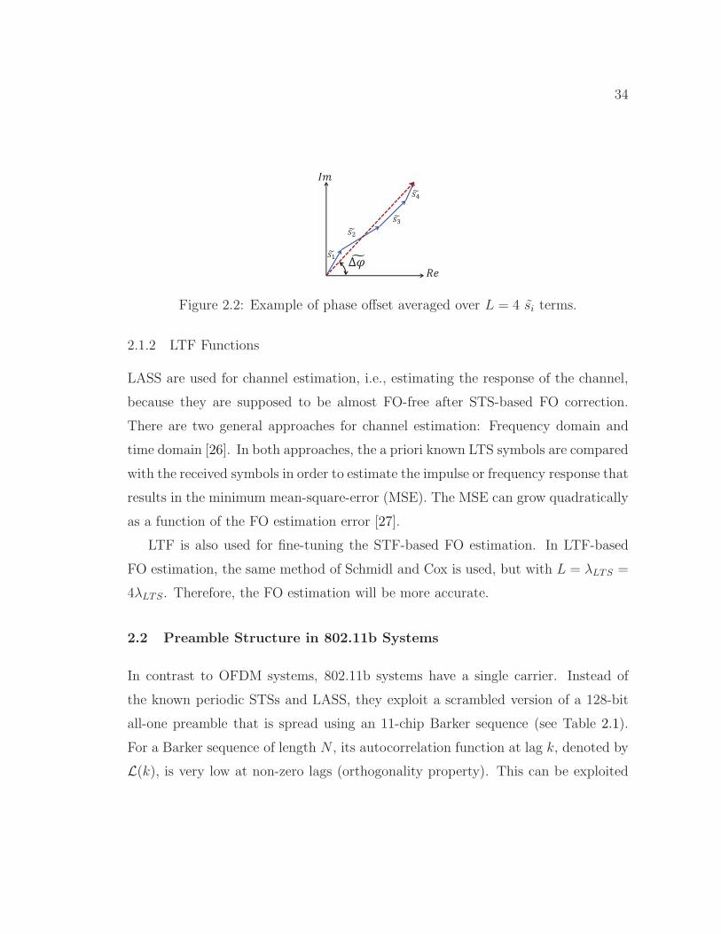
∗L+i has zero mean. To average out the ni’s, the
estimated phase offset, ∆ϕ, is measured over the summation of all the si’s, i.e.,
∆ϕ(ts) = ∡
( L−1∑
i=0
si
)(2.5)
where the notation ∡(x) indicates the phase of a complex value x. Thus, the esti-
mated FO is:
∆f =∆ϕ(ts)
2πLts. (2.6)
Assuming that the channel does not change during the STF, the above method
is independent of the channel. It is widely adopted in practical systems. Figure 2.2
shows an example of a sequence of length 2L = 8 samples. The more the samples
used to estimate ∆ϕ, the more accurate is the estimated FO.
34
Figure 2.2: Example of phase offset averaged over L = 4 si terms.
2.1.2 LTF Functions
LASS are used for channel estimation, i.e., estimating the response of the channel,
because they are supposed to be almost FO-free after STS-based FO correction.
There are two general approaches for channel estimation: Frequency domain and
time domain [26]. In both approaches, the a priori known LTS symbols are compared
with the received symbols in order to estimate the impulse or frequency response that
results in the minimum mean-square-error (MSE). The MSE can grow quadratically
as a function of the FO estimation error [27].
LTF is also used for fine-tuning the STF-based FO estimation. In LTF-based
FO estimation, the same method of Schmidl and Cox is used, but with L = λLTS =
4λLTS. Therefore, the FO estimation will be more accurate.
2.2 Preamble Structure in 802.11b Systems
In contrast to OFDM systems, 802.11b systems have a single carrier. Instead of
the known periodic STSs and LASS, they exploit a scrambled version of a 128-bit
all-one preamble that is spread using an 11-chip Barker sequence (see Table 2.1).
For a Barker sequence of length N , its autocorrelation function at lag k, denoted by
L(k), is very low at non-zero lags (orthogonality property). This can be exploited
35
for frame detection and timing. Formally,
L(k) =∣∣N−k∑
j=1
bjbj+k
∣∣ ≤ 1, 1 ≤ k < N (2.7)
where b = {b1b2 . . . bN} is a Barker sequence. The receiver cross-correlates this
known sequence with the samples of the received signal r = {r1r2 . . . } and computes
the square of the cross-correlation value, denoted by R(b, n):
R(b, n) =∣∣∣
N∑
j=1
b∗jrj+n−1
∣∣∣2
. (2.8)
R(b, n) is expected to peak when the nth sample of r marks the beginning of
one of the transmitted Barker sequences. To improve the detection accuracy, b is
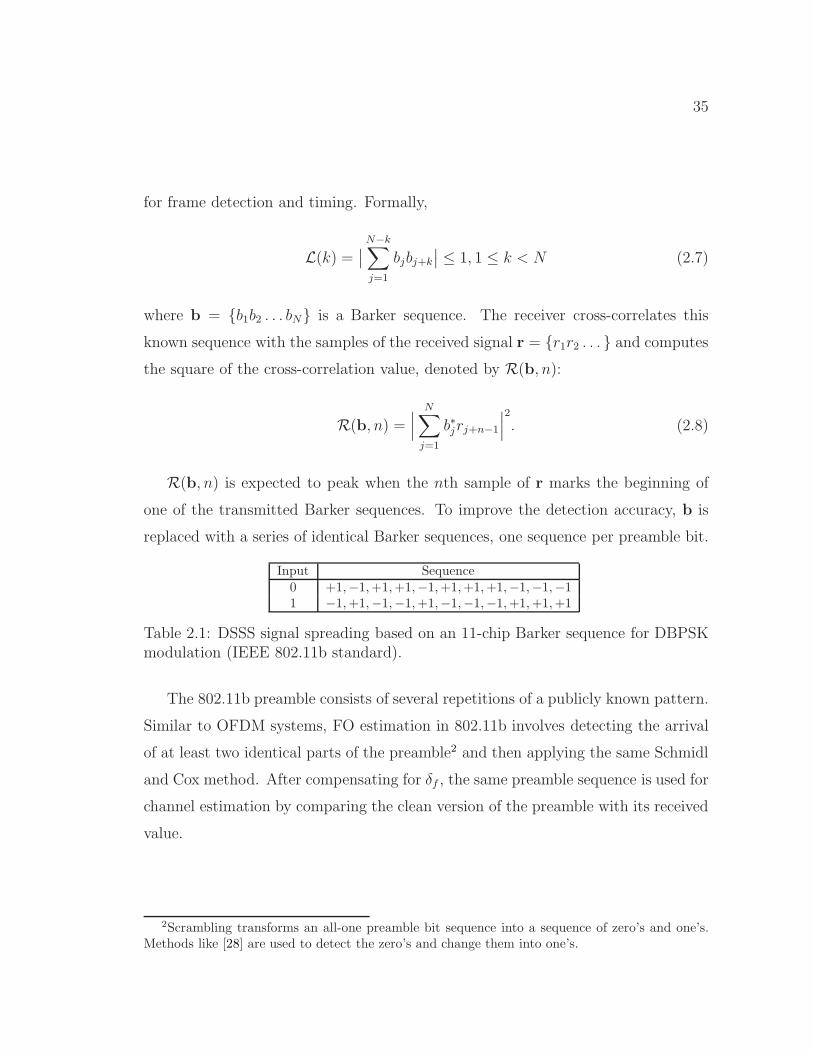
replaced with a series of identical Barker sequences, one sequence per preamble bit.
Input Sequence0 +1,−1,+1,+1,−1,+1,+1,+1,−1,−1,−11 −1,+1,−1,−1,+1,−1,−1,−1,+1,+1,+1
Table 2.1: DSSS signal spreading based on an 11-chip Barker sequence for DBPSKmodulation (IEEE 802.11b standard).
The 802.11b preamble consists of several repetitions of a publicly known pattern.
Similar to OFDM systems, FO estimation in 802.11b involves detecting the arrival
of at least two identical parts of the preamble2 and then applying the same Schmidl
and Cox method. After compensating for δf , the same preamble sequence is used for
channel estimation by comparing the clean version of the preamble with its received
value.
2Scrambling transforms an all-one preamble bit sequence into a sequence of zero’s and one’s.Methods like [28] are used to detect the zero’s and change them into one’s.

36
CHAPTER 3
Jamming of Frequency Offset Estimation in
OFDM Systems
3.1 Introduction
Communication between two wireless devices involves several concerted functions at
the PHY layer, including time synchronization, FO correction, channel estimation,
channel coding, modulation, interleaving, and others [1]. PHY-layer functions are
designed to combat oscillator imperfections and wireless channel impairments, and
to decode wireless signals that are corrupted by a limited amount of interference.
However, due to the leakage of SCI, wireless transmissions still remain vulnerable
to intentional interference attacks, commonly referred to as jamming.
One measure of the effectiveness of a jamming attack is its duty cycle, i.e., the
fraction of the frame that needs to be jammed so that the frame is discarded at
the Rx [29, 30]. This metric is directly related to the jammer’s distance to the Rx,
energy budget, and the ability to disrupt concurrent transmissions. A jammer that
remains active for a longer period can corrupt more bits and defeat stronger error
correction codes (ECCs), at the expense of higher energy consumption and fewer
targeted communications. This more potent jammer is also easier to detect [31],
localize, and physically remove using jammer localization methods [30].
In this chapter, we investigate an extremely low duty cycle jamming model that
is facilitated by public knowledge of the frame structure and PHY-layer functions.
Our goal is to demonstrate how an adversary can inflict the highest possible number
of decoding errors at the Rx, without jamming the corresponding header or payload

37
Figure 3.1: Effect of uncompensated FO on a bitmap image over a noiseless channel(FO = 0.32% of the subcarrier spacing).
symbols. PHY-layer standards usually employ publicly known sequences for their
preambles at the beginning of a frame to acquire important communication param-
eters, such as the transmission timing, channel, and FO [1]. These parameters are
used to align received symbols. An adversary may exploit the publicity of the pream-
ble to construct a reactive jamming attack and target the estimation of these critical
parameters. In particular, we demonstrate the feasibility of an energy-efficient and
low duty cycle attack against the FO estimation process of IEEE 802.11 OFDM-
based devices (including 802.11a, .11g, .11n, .11ac, and 11ah), all of which exploit
the same preamble structure. Our results can be extended to other OFDM-based
systems, including 802.16e/m (WiMAX), LTE, and 5G.
The jamming of OFDM systems has recently been the subject of extensive re-
search (e.g., [20–22, 32–35]). These works often consider vulnerabilities in time
synchronization or susceptibility to ICI. For example, the authors in [20] proposed
several jamming attacks against OFDM time synchronization, including barrage at-
tacks, false preamble timing, and preamble warping. In the barrage attack, white
noise is transmitted to decrease the SNR during synchronization. In false preamble
timing, the jammer forges a preamble to fool the Rx about the true start time of the
frame. A similar technique was used in [33] against an 802.11b Rx to hamper the
network throughput. Preamble warping tries to destroy the time-domain correlation
(used for time acquisition) within the preamble.

38
3.1.1 Existing Attacks Against FO Estimation
In OFDM systems, frequency synchronization errors are more devastating than tim-
ing errors [26]. When two radios are tuned to the same target frequency, their oscil-
lators cannot be exactly aligned to that frequency due to hardware imperfections.
FO is the inherent difference between the actual frequencies of these two oscilla-
tors. In OFDM, FO is usually normalized to the inter-subcarrier frequency interval,
called subcarrier spacing. Without frequency synchronization, the performance of
OFDM degrades severely because all subcarriers will move away from their expected
frequencies, resulting in subcarriers’ orthogonality violation, ICI [26], and channel
estimation errors [27, 36].
To appreciate the significance of correct FO estimation, we conduct a simulation
experiment in which a frame containing a bitmap image is transmitted between
two nodes. Figure 3.1 depicts the effect of a small FO estimation error (0.32% of
subcarrier spacing) on the transmitted image (left) when 48 subcarriers are used
at a rate of 6 Mbps. The received image (right) exhibits noticeable degradation in
the form of image block misplacement. In practice, FO can be even larger than the
subcarrier spacing [1].
A few jamming schemes have been proposed in the literature (e.g., [21, 22, 33])
with the goal of inflicting ICI. Phase warping and differential scrambling attacks [21]
consider the preamble structure of Schmidl and Cox [25], which is different from the
one used in 802.11 OFDM-based standards, and in essence try to alter preamble
symbols in a heuristic fashion without providing any success guarantees. Gummadi
et al. [33] showed the vulnerability of 802.11a clock (frequency) synchronization to
a certain narrow-band jamming pattern that interferes with the entire preamble.
In [22] the jammer transmits multiple asynchronous subcarriers to cause ICI in an
OFDM symbol. These attacks may fail if robust ECC, interleaving methods, or
additional FO estimation mechanisms are employed at the Rx.

39
3.1.2 Main Contributions and Chapter Organization
We design an energy-efficient jamming attack that interferes with a small portion
of the preamble, i.e., one of the parts used for FO estimation, and causes one or
two units shift of the subcarrier indices (e.g., every subcarrier takes the position
of its next/previous subcarrier). To make this design possible, the adversary (Eve)
must first estimate the FO between the legitimate transmitter (Alice) and intended
receiver (Bob), and then quickly detect the transmission of a target frame. We
provide an adaptive frame detection method to facilitate fast detection at Eve.
The superposition of the jamming signal with the preamble are designed to delude
Bob into estimating an FO that is sufficiently far from the true FO, so that Bob
decodes wrong symbols, i.e., the symbols of adjacent subcarriers. The idea is to
come up with a structure that is similar to the actual preamble so as to control
the FO embedded in the jamming sequence. The superposition of these two signals
with different FOs at the Rx achieves sufficient FO estimation error. We derive the
amount of FO estimation error needed to guarantee erroneous OFDM demodulation
and accordingly, develop an optimal attack strategy. To ensure that the jamming
signal is independent of the Alice-Bob channel parameters (which are unknown
to Eve), we propose a pairing scheme for the jamming sequence. The jamming
attack should also account for timing errors in frame detection at Eve while keeping
the jamming signal channel-independent. For this purpose, a chaining scheme is
designed on top of the pairing scheme to account for other possible frame start
times.
Consequently, not only the channel estimation is automatically corrupted at
Bob, but more importantly, all the frequency subcarriers are shifted forward or
backward. Hence, Bob will have a shifted version of the bitstream transmitted
in every OFDM symbol. Combined with a faulty channel estimation and thus
demodulation errors, the bits become irrecoverable. We further optimize the power
of this jamming attack and experimentally evaluate its performance on a USRP

40
testbed. In contrast to previous attacks on the frame preamble, ours in essence does
not aim at necessarily causing ICI. It is also different from the attacks in [21,22,33]
in that it is channel-independent and energy-efficient, i.e., only a small portion of the
preamble is jammed irrespective of the jammer’s location. This short-lived attack
lasts for less than 3 µs per frame (equivalent to, for example, about 0.5% of 802.11a’s
maximum frame duration when the data rate is at its highest value). Note that this
is even shorter than the duration of an OFDM symbol (4 µs). Our proposed attack
also disarms all the provisioned FO estimation methods by just efficiently defeating
one of them. Our work focuses on the 802.11 OFDM-based wireless systems, and
efficiently exploits their FO vulnerability for the first time.
The chapter is organized as follows. In Section 3.2, we provide background
on the consequences of FO in OFDM-based 802.11 OFDM systems. The system
model, assumptions, and evaluation metrics are given in Section 3.3. The proposed
attack and the optimal jamming strategy are presented in Section 3.4 and related
issues are discussed in Section 3.5. Section 3.6 demonstrates the effectiveness of the
attack through simulations and experiments. Finally, we propose possible remedies
in Section 3.7.
3.2 FO in OFDM Systems
In OFDM, a bitstream is split into several substreams, each of which is digitally
modulated and transmitted over one of the orthogonal frequency channels (sub-
carriers). For example, 802.11a/g defines 64 subcarriers with subcarrier spacing
f∆ = 312.5 kHz within a bandwidth of 20 MHz. Only 48 of these subcarriers
are used for data. Four other subcarriers carry pilot signals and the remaining 12
subcarriers are not used. So an 802.11a/g OFDM symbol is transmitted over 52
subcarriers.
ICI in OFDM systems creates significant BER at the Rx [37] (see Figure 3.2).
To prevent ICI, the Rx uses the PHY-layer preamble to estimate the FO (same for

41
FO
ICI
f
ICI
f
ICI
Figure 3.2: Inter-carrier interference (ICI) as a result of uncorrected FO in a systemwith three subcarriers.
all subcarriers) and adjust the subcarriers to their expected orthogonal frequency
bins. If the offset is less than half of the frequency distance between the subcarriers,
the Rx can safely identify the frequency bin that each subcarrier belongs to.
As explained in Chapter 2, the preamble in OFDM-based 802.11 systems contains
two essential fields: STSs and LTSs (see Figure 6.1). The periodic function in an
STS is constructed by superposing only the subcarriers whose frequencies are integer
multiples of 4f∆. As a result, the minimum subcarrier spacing between any two STS-
enabled subcarriers is 4f∆, and hence their period is λSTS = λLTS/4. STSs are used
for frame detection and coarse FO correction. LTSs, on the other hand, employ
all the data subcarriers and are used for channel estimation and fine-tuning the
coarse STS-based FO estimation. In addition to causing ICI, a linear increase in the
phase offset during the LTSs due to FO (i.e., ∆ϕ(t) = 2π∆ft) results in incorrect
channel phaser estimation. To compensate for channel impairments, the inverse of
the phaser is multiplied to the received samples. As a result, all received modulated
samples will be rotated equally on the constellation map, leading to more bit errors.
Beyond channel estimation errors, accumulation of the phase offset can significantly
change the phase of some of the symbols, especially in long frames.
Regarding the phase of a complex number such as si during FO estimation, the
Rx observes a value between −π and π. In other words, the Rx cannot distinguish
∆ϕ from ∆ϕ± 2kπ in (2.6), for any integer k. The phase offset of 2π corresponds

42
to 1Lts
offset, i.e., one subcarrier spacing. In particular, consider a subcarrier and
two FOs from it, ∆f1 and ∆f2, where |∆f1| ≤ 12Lts
and |∆f2| = |∆f1| + 1Lts
. The
corresponding phases are 2π|∆f1|Lts and 2π|∆f1|Lts+2π, respectively. Because the
phases differ by 2π, there will be an ambiguity in distinguishing between them. The
Rx interprets ∆f1 +1
Ltsas ∆f1 and will mistakenly adjust ∆f2 to the neighboring
subcarrier bin. In general, the phase is unambiguous and correctable as long as
|∆f | < 12Lts
(half a subcarrier spacing). This also implies that a longer period of a
cycle reduces the range of FO that can be corrected unambiguously. Given a fixed
sampling interval, a longer period results in higher L.
Let ths and thl be the maximum |∆f | values that STSs and LTSs can correct
unambiguously, respectively. In the 802.11a/g, two of the last three STSs are chosen
to form a sequence with two identical halves for coarse FO estimation. Since the
number of samples of an LTS is four times the number of samples of an STS, then
thl = ths/4 = f∆/2.
The above discussion reveals a tradeoff between the accuracy and range of the
correctable FO. The goal of the STSs is to estimate a large FO value and compensate
for it by multiplying the rest of the samples (including those obtained during the
LTSs) by e−j(−2π∆fs i ts), where ∆fs is the estimated FO in the STSs phase and i is
the sample index. Using LTSs, the Rx then computes ∆fl to fine-tune the coarsely
estimated FO. This explains one of the reasons for concatenating short and a long
training fields in 802.11 systems. Consequently, if the actual FO is larger than ths,
this FO estimation method fails to fully compensate for it.
Even after the LTS-based FO correction, a small residual FO may remain due
to noise. This error is typically too small to cause ICI, but it gradually rotates
the phase of the received symbols on the constellation map and may increase the
BER, specially in the long frames. A predetermined subset of subcarriers with
known values (called pilot subcarrier) are used to track and compensate for these
small phase changes. Theoretically, there is no frequency range limitation for FO

43
estimation in pilot subcarriers [26]. In addition, known pilot subcarriers can be used
for tracking channel variations.
3.3 Model and Assumptions
We consider a link between Alice (the Tx) and Bob (the Rx). The adversary (Eve) is
in the transmission ranges of both Alice and Bob. Alice transmits an 802.11 OFDM
frame and Bob uses a few of the first STSs for frame detection. He chooses two of
the last three STSs, in conformity with the standard (see Figure 6.1) and employs
the Schmidl and Cox method for FO estimation. Once Bob estimates the coarse FO
using STSs and compensates for ∆fs, he assumes, by default, that the residual FO
is less than thl and then estimates it using LTSs. According to the 802.11 standard,
Bob does not perform any kind of boundary check during the LTS- and pilot-based
FO estimation processes.
Eve aims at irrecoverably corrupting Alice’s frame at Bob using the lowest pos-
sible jamming effort. Eve is aware of the PHY-layer protocol and the FO correction
mechanism at Bob. She makes no assumptions about the channel parameters or Al-
ice’s transmission power. If the oscillators are either stable or accurate, Eve initially
eavesdrops on Alice’s and Bob’s preamble transmissions (e.g., data-ACK exchanges)
for a while. Through averaging, she estimates their FOs relative to Eve, denoted by
∆fae and ∆fbe, respectively1.
The metrics of interest are coarse and final estimated FOs at Bob, symbol error
rate (SER), the BER after demodulation but before decoding, and the jamming
effort (defined as the jammer’s duty cycle [29]). These metrics will be studied with
respect to the SNR, modulation scheme, and signal-to-jamming ratio (SJR) at Bob.
1In general, oscillators exhibit numerous instabilities, due to aging, temperature, acceleration,ionizing radiation, power supply voltage, etc. Thus, the Rx must update the FO estimate on aper-frame basis, even if the frame sender is already known. This is specially the case with non-stable oscillators. In this case, Eve can perform FO estimation along with fast frame detection tooptimally design the jamming signal for each frame (see Section 3.4.1).

44
3.4 Proposed Frequency Offset Estimation Attack
In this section, we describe in detail an attack on the FO estimation. Eve launches
this attack in two phases: (1) Eavesdropping on the channel to detect the start of
Alice’s frame transmission and acquire its timing information; and (2) jamming the
last three STSs of the preamble, which are used for coarse FO estimation.
3.4.1 Phase 1: Adaptive Fast Frame Detection
To pinpoint the last three STSs in time and corrupt the FO estimation at Bob, Eve
must detect Alice’s frame and synchronize with its arrival at Bob. The detection
should be fast enough to allow sufficient time for processing, switching to trans-
mission mode, and jamming the last three STSs. Referring to the frame detection
mechanism in Section 3.2, Eve chooses the minimum possible window size (one STS,
L = 16) and reduces the capture time to 2.5λSTS = 2 µs to make sure that at least
the first two STSs are captured.
To account for the higher detection inaccuracy due to the small window size, Eve
assumes that the actual start time belongs to the first V = log2(L)2 sample indices
i0, i1, . . . , iV−1 that are greater than (1− ǫ)M and finds all of them, instead of just
looking for the first one. She sets ǫ to a value less than 1/L, the contribution of a
preamble sample pair inM(n). This is an attempt to exclude the samples located
more than one index before the actual frame start time. If there are less than V
sample values greater than the threshold, Eve adaptively decreases the threshold by
finding the smallest ǫ that guarantees the existence of V candidates3.
3.4.2 Phase 2: Preamble Jamming
Based on i0, Eve computes the arrival time of the last three STSs of the preamble
and generates a jamming signal that would be aligned with those STSs. The energy-
2The reason of this specific number will be explained in Section 3.4.2.3Eve may also apply the synchronization method in [38] to improve the detection accuracy.
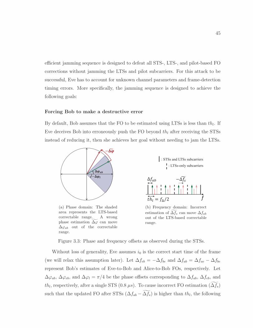
45
efficient jamming sequence is designed to defeat all STS-, LTS-, and pilot-based FO
corrections without jamming the LTSs and pilot subcarriers. For this attack to be
successful, Eve has to account for unknown channel parameters and frame-detection
timing errors. More specifically, the jamming sequence is designed to achieve the
following goals:
Forcing Bob to make a destructive error
By default, Bob assumes that the FO to be estimated using LTSs is less than thl. If
Eve deceives Bob into erroneously push the FO beyond thl after receiving the STSs
instead of reducing it, then she achieves her goal without needing to jam the LTSs.
(a) Phase domain: The shadedarea represents the LTS-basedcorrectable range. A wrongphase estimation ∆ϕ can move∆ϕab out of the correctablerange.
f
: STSs and LTSs subcarriers
: LTSs-only subcarriers
(b) Frequency domain: Incorrect
estimation of ∆fs can move ∆fabout of the LTS-based correctablerange.
Figure 3.3: Phase and frequency offsets as observed during the STSs.
Without loss of generality, Eve assumes i0 is the correct start time of the frame
(we will relax this assumption later). Let ∆feb = −∆fbe and ∆fab = ∆fae − ∆fbe
represent Bob’s estimates of Eve-to-Bob and Alice-to-Bob FOs, respectively. Let
∆ϕab, ∆ϕeb, and ∆ϕl = π/4 be the phase offsets corresponding to ∆fab, ∆feb, and
thl, respectively, after a single STS (0.8 µs). To cause incorrect FO estimation (∆fs)
such that the updated FO after STSs (∆fab− ∆fs) is higher than thl, the following
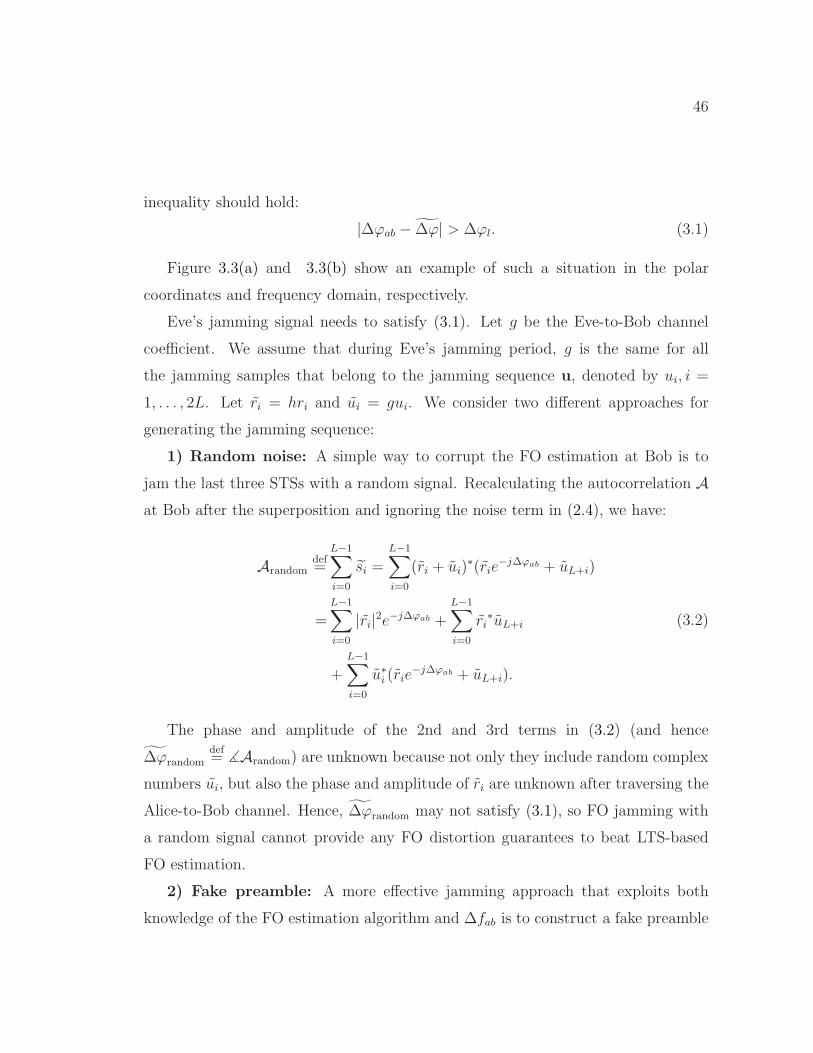
46
inequality should hold:
|∆ϕab − ∆ϕ| > ∆ϕl. (3.1)
Figure 3.3(a) and 3.3(b) show an example of such a situation in the polar
coordinates and frequency domain, respectively.
Eve’s jamming signal needs to satisfy (3.1). Let g be the Eve-to-Bob channel
coefficient. We assume that during Eve’s jamming period, g is the same for all
the jamming samples that belong to the jamming sequence u, denoted by ui, i =
1, . . . , 2L. Let ri = hri and ui = gui. We consider two different approaches for
generating the jamming sequence:
1) Random noise: A simple way to corrupt the FO estimation at Bob is to
jam the last three STSs with a random signal. Recalculating the autocorrelation Aat Bob after the superposition and ignoring the noise term in (2.4), we have:
Arandomdef=
L−1∑
i=0
si =
L−1∑
i=0
(ri + ui)∗(rie
−j∆ϕab + uL+i)
=
L−1∑
i=0
|ri|2e−j∆ϕab +
L−1∑
i=0
ri∗uL+i
+L−1∑
i=0
u∗i (rie
−j∆ϕab + uL+i).
(3.2)
The phase and amplitude of the 2nd and 3rd terms in (3.2) (and hence
∆ϕrandomdef= ∡Arandom) are unknown because not only they include random complex
numbers ui, but also the phase and amplitude of ri are unknown after traversing the
Alice-to-Bob channel. Hence, ∆ϕrandom may not satisfy (3.1), so FO jamming with
a random signal cannot provide any FO distortion guarantees to beat LTS-based
FO estimation.
2) Fake preamble: A more effective jamming approach that exploits both
knowledge of the FO estimation algorithm and ∆fab is to construct a fake preamble

47
with “identical halves”. For now, assume that the samples of the jamming signal
ui, i = 1, . . . , 2L can take any arbitrary value as long as the signal conforms to
the protocol bandwidth requirement. The preamble phase warping attack in [21] is
a special case of this approach, where the jamming signal is a random frequency-
shifted version of an arbitrary fake preamble. The advantage of having identical
halves is that we can control and carefully calculate a desired FO for u based on
how Bob estimates ∆fab. Here, we also note that the channel response between Eve
and Bob does not change the FO. Before we explain how a desired FO (and hence
∆feb) is determined, consider the superposition of Alice’s signal and Eve’s jamming
at Bob. Dropping the index i from (2.4) and ignoring the noise term, we have:
s = (r + u)∗(re−j∆ϕab + ue−j∆ϕeb) = e−j∆ϕab×[|r|2 + |u|2e−j(∆ϕeb−∆ϕab) + r∗ue−j(∆ϕeb−∆ϕab) + u∗r︸ ︷︷ ︸
B
].
(3.3)
Thus, the estimated phase offset at Bob is:
∆ϕ = ∡s = ∆ϕab + ∡B + ∡n. (3.4)
Note that the phase estimation error ϕedef= ∡B is a function of SJR and ∆ϕeb, and
jamming will have no effect if ϕe = 0.
Upon calculating ∆ϕ and ∆fs, Bob changes the FO for the rest of the frame
to ∆fab − ∆fs. According to (3.1), Eve is successful if she can ensure that ∆ϕeb
satisfies the following:
|∆ϕab − ∆ϕ| > ∆ϕl ⇒ |ϕe + ∡n| > ∆ϕl =π
4. (3.5)
Eve can guarantee a desired ϕe only if SJR→ −∞. Otherwise, even if she
knows ∆ϕab and u and can also control ∆ϕeb, she has no control over other channel-

48
dependent parameters in B. Specifically, the phase and amplitude of r are channel-
dependent and Eve cannot estimate the Alice-to-Bob channel coefficient h. That
means that Eve is still unable to guarantee a successful attack, which is also the
case in the preamble phase warping attack.
Designing a channel-independent jamming signal
To address the aforementioned challenge, Eve takes advantage of Alice’s known
preamble samples and the product sum in (2.5) to cancel out the terms with un-
known phases. Eve first chooses L/2 non-overlapping pairs of samples. Without
loss of generality, let Eve pair the samples in order and let (u1, u2) be the first pair
of samples in the jamming sequence. By knowing the preamble sample values at
Alice, u2 can be designed such that when Bob sums up s1 and s2, all the terms that
depend on r (excluding |r|) in the term B in (3.3) are eliminated. Thus,
u2 = −r∗1r∗2u1 (3.6)
which implies that
s1 + s2 = e−j∆ϕab×[|r1|2 + |r2|2 + (|u1|2 + |u2|2|) e−j(∆ϕeb−∆ϕab)
].
(3.7)
The requirement in (3.6) is similarly imposed on the rest of the even samples.
We refer to this requirement as the pairing rule. Accordingly, the autocorrelation

49
function A for this scheme, denoted by Afake, becomes:
Afake =
L−1∑
i=0
si =
e−j∆ϕab
[ L−1∑
i=0
|ri|2 +L−1∑
i=0
|ui|2 e−j(∆ϕeb−∆ϕab)]
︸ ︷︷ ︸C(∆ϕeb−∆ϕab)
.(3.8)
Now Afake is a function of the difference between ∆ϕab and ∆ϕeb only. So Eve can
determine a desired value of ∆ϕeb in a way that makes |∡C(∆ϕeb −∆ϕab)| > ∆ϕl,
which satisfies (3.5).
Robustness to errors in frame start time
We now relax the assumption that Eve can precisely determine the true frame start
time and consider a scenario in which she compiles a short list of possible frame
start times besides i0, as explained in Section 3.4.1. Thus far, we have required
the jamming sequence to have identical halves with a ∆ϕeb that satisfies (3.5) and
the even samples to be a function of odd samples (pairing rule). Eve could still
benefit from the remaining free, unassigned samples (i.e., odd samples) to cancel out
channel-dependent terms for other possible start times. We generalize the pairing
technique to larger sets of samples and define the following chaining rule to account
for V − 1 other start times i1, i2, . . . , iV−1.4
Let m = {m0, . . . , mV−1} where mj = ij − i0. First, Eve extends her jamming
sequence by appending (cyclically postfixing) the first mV−1 jamming samples to
this sequence. So for any candidate frame start time ij, the jamming signal will
be fully superposed on Alice’s three STSs because the jamming signal is cyclically
extended already by mV−1 > mj samples. Next, Eve assumes that i1 is the correct
4Eve can precompute and then account for the propagation delays by timestamping the data-ACK exchanges between Alice and Bob and estimating the Eve-to-Bob distance. The chainingrule can also be leveraged to account for errors in estimating these delays.

50
frame start. In this case, the superposition of the jamming signal on Alice’s three
STSs will be different from the previous case (i.e., the jamming sequence is slid with
respect to Alice’s STSs) and (3.6) is no longer sufficient to eliminate the last two
channel-dependent terms within B in (3.3). Instead, Eve can find pairs of yet free
samples and, similar to the pairing rule, define one of the samples of each of such
pairs based on the other sample of that pair and also the corresponding samples in
r. After this step, half of the free samples will be given values. Eve repeats the same
procedure for the rest of the frame start times and free samples. Based on these
hierarchical dependencies among the samples ui, Eve constructs a binary chaining
tree in which the dependency between two samples is mapped to a parent-child
relationship. Note that an unassigned (free) sample may already have a chain of
other dependent sample(s). The value of the dependents will be updated whenever
that sample takes a new value.
1 14132 116 155 164 7 8 93 10 12
1 14132 116 155 164 7 8 93 10 12
1 1311 155 7 93
1 135 9
1 9
1
1 14132 116 1554 7 8 93 10 1216
1 132 11654 7 8 93 10 1215 1614
1 2 11654 7 8 93 10 1214 15 1613
Jamming seed
Figure 3.4: Cascaded chaining and pairing of the samples towards the jamming seed.Jamming samples are shown on the tree and the shifted versions of Alice’s pream-ble on the bottom. Horizontal dashed lines represent direct dependency betweensamples.

51
An example is depicted in Figure 3.4 with m = {0, 1, 3, 4}. Without loss of
generality, we assume Alice’s preamble sequence is shifted instead of the jamming
sequence. The tree in this figure shows how the jamming samples are being chained
together and used to construct the tree from the bottom to the top. A pair of free
samples are considered as siblings. The left child specifies the value of its right
sibling based on mj and then the left child is copied to its parent node. So the right
child depends on its sibling. To explicitly define the dependency between the two
sibling samples, all their dependent samples must also be taken into account because
their values in (3.3) are affected by their parents’ values. For example, when j = 1,
Eve may select two free samples u1 and u3 (together with their dependents u2 and
u4) to eliminate the channel-dependent terms:
u∗1r16 + u∗
2r1 + u∗3r2 + u∗
4r3 = 0 (3.9)
which implies the dependency of u3 to u1 (u2 and u4 are substituted by their corre-
sponding pairing rule dependencies on u1 and u3):
u∗3 = −
r4(r2r16 − r1r1)
r2(r2r4 − r3r3)u∗1. (3.10)
Now the value of the dependent of u3 (u4 in this example) is updated to maintain
its dependency relationship with the right sibling u3.
A pseudocode of the chaining rule, which also contains the pairing rule, is pro-
vided in Algorithm 1. The algorithm iterates for each mj , j = 1, . . . , V − 1. At
each iteration and for each pair of free samples, the right subtree (the right siblings
of all its 2j − 1 dependents) is multiplied by a coefficient x (defined in line 8) such
that the summation of the corresponding 2j product terms in (3.3) and the 2j terms
corresponding to the left subtree is zero. The horizontal arrows in Figure 3.4 show
the dependence of the right subtrees on their left subtrees. As a result, L/2j sam-
ples are assigned at each iteration and the algorithm terminates after V = log2(L)

52
Algorithm 1 Chaining and pairing rules combined
1: Input: L, V, r[1 . . . L],m[0 . . . V − 1]2: Initialize: u = 03: for j ← 0, V − 1 do4: k ← 2j
5: while k < L do6: t = circularly shifted r by mj
7: x = −∑k
i=k−2j+1 uit∗i /
∑k+2j
i=k+1 uit∗i
8: [uk, . . . , uk+2j−1] = [uk, . . . , uk+2j−1] ∗ x9: k = k + 2j+1
10: end while11: end for12: Return u
iterations. In the end, all but one of the samples (u1 in our example) will be a
right sibling at least once at some point in the tree and so are assigned. We call
the remaining free sample the jamming seed, to which all the samples are chained
either directly or recursively. The jamming seed can be used to control the jamming
power.
3.4.3 Effects of LTSs on FO and Channel Estimation
LTSs are used for fine FO and channel estimation. As explained in Section 3.2, the
phase offset from the LTS-based FO corresction perspective is between −π and π,
which means that the true FO after STS-based correction has to be between −thl
and thl. So LTSs can correct up to thl = f∆/2 FO, and any remaining phase offset
will be an integer multiple of 2π, which corresponds to 2k thl = kf∆, k = 1, 2, . . . .
In other words, the LTSs at Bob round up the FO manipulated by ∆fs to the
nearest multiple of 2thl and avoid ICI by adjusting the subcarriers to the closest,
though incorrect, frequency bins. Consequently, in this attack all the subcarriers will
be shifted forward or backward, replacing neighboring subcarriers. Bob eventually
demodulates the bits of all OFDM symbols, but he is unaware that these symbols
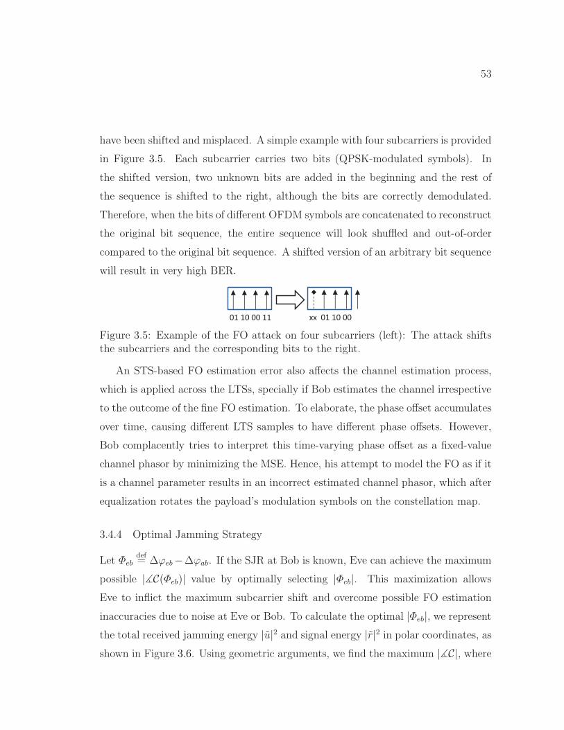
53
have been shifted and misplaced. A simple example with four subcarriers is provided
in Figure 3.5. Each subcarrier carries two bits (QPSK-modulated symbols). In
the shifted version, two unknown bits are added in the beginning and the rest of
the sequence is shifted to the right, although the bits are correctly demodulated.
Therefore, when the bits of different OFDM symbols are concatenated to reconstruct
the original bit sequence, the entire sequence will look shuffled and out-of-order
compared to the original bit sequence. A shifted version of an arbitrary bit sequence
will result in very high BER.
01 10 00 11 xx 01 10 00
Figure 3.5: Example of the FO attack on four subcarriers (left): The attack shiftsthe subcarriers and the corresponding bits to the right.
An STS-based FO estimation error also affects the channel estimation process,
which is applied across the LTSs, specially if Bob estimates the channel irrespective
to the outcome of the fine FO estimation. To elaborate, the phase offset accumulates
over time, causing different LTS samples to have different phase offsets. However,
Bob complacently tries to interpret this time-varying phase offset as a fixed-value
channel phasor by minimizing the MSE. Hence, his attempt to model the FO as if it
is a channel parameter results in an incorrect estimated channel phasor, which after
equalization rotates the payload’s modulation symbols on the constellation map.
3.4.4 Optimal Jamming Strategy
Let Φebdef= ∆ϕeb−∆ϕab. If the SJR at Bob is known, Eve can achieve the maximum
possible |∡C(Φeb)| value by optimally selecting |Φeb|. This maximization allows
Eve to inflict the maximum subcarrier shift and overcome possible FO estimation
inaccuracies due to noise at Eve or Bob. To calculate the optimal |Φeb|, we representthe total received jamming energy |u|2 and signal energy |r|2 in polar coordinates, as
shown in Figure 3.6. Using geometric arguments, we find the maximum |∡C|, where

54
1 BW shift
2 FW shifts
2 BW shifts
1 FW shift
Figure 3.6: Superposition of Alice’s and Eve’s signals at Bob and the resulting sub-carrier shifts. The minimum feasible |u|2 occur when the vector |u|2 is perpendicularto an edge of the 1-shift regions. The parts of a contour crossing the shaded areasshow the feasible phases for a given |u|2.
C = |r|2 + |u|2e−j(Φeb). Each circular contour in this figure shows the end points of
the vector C for a given SJR but different Φeb values.
As long as |u| < |r|, |∡C| reaches its maximum when the vector C is tangent to
the contour circle. In a right triangle, this implies
|∡C| = arcsin|u|2|r|2 (3.11)
and
|Φeb| = π/2 + ∡C. (3.12)
When |u| ≥ |r|, the maximum ∡C equals to π, which is always achieved when
|Φeb| = π. In Figure 3.7, we plot the corresponding optimal |∆feb−∆fab| during the
STSs for different SJR values. Based on ∡C, we also derive the resulting number of
subcarrier-spacings shift after LTSs. Note that phase offsets π/2 and π correspond
to FOs of one and two f∆’s, respectively. From the STSs perspective, LTSs adjust
a phase offset to its closest multiple of 2ϕl. So when |∡C| > 3ϕl, the attack results
in a shift of two subcarriers.
The jamming sequence can be designed to minimize the total jamming energy∑L−1
i=0 |ui|2, subject to the constraint of at least one subcarrier shift, i.e., |∡C(Φeb)| ≥

55
−1 0 1 2 31.2
1.4
1.6
1.8
2
SJR (dB)
| ∆ f
eb−
∆ f ab
| (no
rmal
ized
to f ∆)
−1 0 1 2 3−2
−1
0
Num
ber
of f ∆ s
hifts
in s
ubca
rrie
rs a
t Bob
Optimal | ∆ feb
−∆ fab
|
Subcarriers shift
Figure 3.7: Optimal |∆feb − ∆fab| and resulting amount of subcarrier shift fordifferent SJR values.
∆ϕl. The shaded area in Figure 3.6 shows the feasible region. According to (3.11)
and the geometry in Figure 3.6, we conclude that:
1. The energy minimization problem is feasible as long as
SJR =
∑L−1i=0 |ri|2∑L−1i=0 |ui|2
≤ 1
sin (∆ϕl)=√2 ≈ 1.5 dB. (3.13)
2. The minimum jamming energy is achieved when
|∆ϕeb −∆ϕab| = |π/2 + ∆ϕl| = 3π/4, (3.14)
or equivalently, |∆feb −∆fab| = 1.5 f∆.
Equation (3.14) says that the phase offset of Eve’s signal as perceived by Bob
should have phase difference of |π/2 + ∆ϕl| relative to Alice’s signal. Even if ∆ϕeb
does not satisfy (3.14), Eve can augment the hardware-dependent ∆feb and obtain
an effective ∆feb by imposing an artificial FO of ∆fn on the jamming sequence before
it is transmitted by the oscillator. This is achieved by multiplying the samples of
the jamming sequence by e−j2π∆fn i ts , where ∆fn is given by:
∆fn = ±1.5 f∆ −∆feb +∆fab. (3.15)
56
The optimal |Φeb| that minimizes the jamming energy is particularly important in
designing the optimal jamming strategy because the SJR at Bob is usually unknown
to Eve. The optimal jamming strategy to deal with this situation is to consider the
worst-case (highest) SJR under which the attack is successful and then set the
effective FO according to (3.14). Therefore, Eve always sets Φeb to ±(π/2 + ∆ϕl).
3.5 Discussion
OFDM-based 802.11 systems employ interleaving and adaptive modulation and cod-
ing (AMC) schemes to increase resiliency against jamming and bit errors. However,
the achieved BER value of the aforementioned FO attack (∼ 0.5) is high enough
that the mutual information between the transmitted and received sequences is zero,
and hence practical coding schemes cannot recover the frame. After an unsuccessful
transmission and subsequent data rate reduction, Alice may increase her transmit
power for the whole frame. In the case of the proposed FO attack, such an increase
is unnecessary and inefficient for the payload, which constitutes up to 99.9% of a
frame. In addition, an intelligent jammer can track Alice’s power increase (e.g., by
overhearing management frames), adjust the jamming power to always achieve the
optimal SJR, and force the dropping of subsequent transmissions.
It may also be argued that because pilot subcarriers are transmitted on known
frequencies, Bob can compare the known symbols of the pilot subcarriers with the
received symbols on different subcarriers to identify a possible subcarrier shift. How-
ever, because channel estimation is distorted, locating the corrupted pilot subcarriers
at Bob is quite challenging. Furthermore, these pilot subcarriers cannot be easily
used for channel estimation (we leave the investigation of this problem to a future
work).
Moreover, we note that jamming the LTSs after jamming the STSs strengthens
the attack by further distorting the channel estimation process. However, jamming
the LTSs alone cannot lead to a subcarrier shift even though it involves more jam-
57
ming effort (8-µs duration on 48 subcarriers) than jamming three STSs (≤ 3 µs
on 12 subcarriers). Furthermore, with LTSs jamming, pilot subcarriers can still be
used to estimate the channel and correct any residual FO.
The system model in this chapter assumes a single Tx-Rx-pair (i.e., Alice and
Bob, and hence their FO, are known). In the case of multiple Tx-Rx pairs, Eve
can construct a database of the FOs between different Tx-Rx pairs. Benefiting from
CSMA/CA channel access mechanism, Eve can consider one transmission at a time
and then leverage protocol semantics (e.g., data-ACK exchanges) to guess the Tx
and Rx of an upcoming transmission. Further investigation of this issue is left for
future work.
3.6 Performance Evaluation
In this section, we evaluate the effectiveness of the FO estimation attack through
simulations and USRP experiments. We implemented the 802.11a/g preamble (in-
cluding both short and long training sequences) by extending the PHY-layer library
functions of LabVIEW. Alice appends 1500 modulated random bits to the frame
preamble. Pilot-based channel and FO estimation and channel coding were not
implemented to concentrate on the specific effects of the FO attack on received un-
coded bits. The impact of coding and pilot subcarriers was discussed in Section
3.5.
We assume that Bob uses the STSs t9 and t10, as defined in Figure 6.1, for coarse
FO estimation, followed by fine FO estimation using LTSs. Channel estimation is
performed over the first LTS using the time domain method [26]. We first evaluate
the performance under a simulated AWGN channel model and later in a multi-path
indoor environment. (More results are provided in [39].) We vary the SJR, the
SNR (noise level), the modulation scheme, and Eve’s effective FO, denoted by Deb.
In particular, we consider BPSK, QPSK, and 16-QAM modulation schemes. We
measure ∆fs as well as final estimated FO, SER, and BER.
58
We compare three cases: 1) jamming the last STSs with a random signal (see
Section 3.4.2), 2) FO attack with pairing rule only (V = 1 and L = 16 for frame
detection), and 3) the entire FO attack including the chaining rule, with L = 16
and V = log2 L. The purpose of evaluating the second case is to study the impact
of the chaining rule. The jamming duration for the second case is always equal to
the sum of the durations of t8 and t9. However, it is not constant when the chaining
rule is applied, and depends on mV−1.
3.6.1 Simulations
We consider an AWGN channel model without signal attenuation. In our simula-
tions, the SJR is normalized to the energy of two full STSs. However, the chaining
rule results in a variable-length cyclic postfix extension, which sometimes has a
slightly higher sample power than the average sample power over an STS.
Frame Detection and Jamming Duration
Initially, we assess the accuracy of our adaptive fast frame detection method at Eve
and also its impact on the jamming duration. Even though our adaptive detection
method uses a small window of L = 16 compared to L = 48 for the default scheme,
adapting ǫ based on finding V frame-start candidates increases the probability of
precise frame detection even for the first candidate. This is shown in Figure 3.8,
where each probability is calculated based on more than 25000 runs. By including
additional V − 1 candidate start times, we further increase the probability of in-
cluding the true start time in V candidates, specially under high noise levels. The
chaining rule benefits from V start times because it equally likely considers all the
candidate start times to construct the jamming signal.
The jamming duration depends onmV−1 and the amount of postfix extension. In
Table 3.1, we report the average index-distance between the first and the last samples
(mV−1) in the set of V start times when an STS contains L = 16 samples. The table

59
10 20 30 40 500
0.2
0.4
0.6
0.8
1
SNR (dB)
Pro
b. o
f Pre
cise
Fra
me
Det
ectio
n at
Eve
Fast Frame Detection, 1st candidate
Fast Frame Detection, all 4 candidates
Default Frame Detection, 1st candidate
Figure 3.8: Performance of different variants of frame detection vs. SNR (simula-tions).
shows that even at low SNR, the amount of cyclic extension due to the chaining
rule is often less than half an STS. In particular, in 99.88% of the cases, mV−1 ≤ 8,
which means the jamming duration will be less than 3.5λSTS or, equivalently, 0.7
of an OFDM-symbol duration. A 1500-bit BPSK-modulated payload lasts for 32
OFDM symbols, equivalent to 160 λSTS. The durations of 16-QAM-modulated and
QPSK-modulated signals of the same payload will be 40 and 80 λSTS, respectively.
So the jamming effort in our simulations is upper bounded by 2.0%, 3.5%, and 5.9%
for BPSK, QPSK, and 16-QAM-modulated payloads, respectively. In general, an
802.11a frame lasts for 20 × 10−6 + ⌈(22 + LENGTH)/DATARATE⌉ seconds [1],
where LENGTH and DATARATE denote the encoded payload size (in bits) and
the data rate, respectively. For a typical 802.11a frame [29], the jamming effort
varies between 0.07% and 0.88%, depending on the code and data rates. This is
30% less than the effort of the OFDM symbol jamming attack in [29].
SNR (dB) 5 10 15 20 25 30E(mV−1) 4.05 3.74 3.54 3.23 3.02 3.0
Table 3.1: Average value of mV−1 in the chaining rule for different SNR levels.

60
0 0.5 1 1.5 2−0.4
−0.2
0
0.2
0.4
0.6
Effective FO Deb
(normalized to f∆)
E[∆
f s](normalized
tof ∆
)
w/ chaining
w/o chaining
(a) Impact of the effective Eve-to-BobFO on the performance of the coarseFO estimation (SJR = 1.59 dB andSNR = 25 dB).
−50 −40 −30 −20 −10
0
0.1
0.2
0.3
0.4
0.5
Noise power (dBm)
E[∆
f s](normalized
tof ∆
)
w/ chaining
w/o chaining
Random FO jammer
(b) Impact of the noise level on theperformance of the FO attack (SJR= 1.59 dB and Deb = 1.52 f∆).
0 0.5 1 1.5 2
0
0.2
0.4
0.6
0.8
1
Effective FO Deb
(normalized to f∆)
Est
imat
ed F
O a
t Bob
(no
rmal
ized
to f
∆)
w/ chaining
w/o chaining
(c) Impact of the effective Eve-to-BobFO on the estimated FO at Bob (SJR= 1.3 dB and SNR = 25 dB).
−0.5 0 0.5 1 1.5 2 2.5
0
0.2
0.4
0.6
0.8
1
SJR (dB)
Est
imat
ed F
O a
t Bob
(no
rmal
ized
to f
∆)
w/ chaining
w/o chaining
Random FO jammer
(d) Impact of SJR on the estimatedFO at Bob (SNR = 25 dB and Deb =1.52 f∆).
0 0.5 1 1.5 20
0.2
0.4
0.6
0.8
1
Effective FO Deb
(normalized to f∆)
SE
R
BPSK
QPSK
16−QAM
(e) SER performance for differentmodulation schemes (SJR = 1.59 dBand SNR = 30 dB).
0 0.5 1 1.5 20
0.1
0.2
0.3
0.4
0.5
Effective FO Deb
(normalized to f∆)
BE
R
BPSK
QPSK
16−QAM
(f) BER performance for differentmodulation schemes (SJR= 1.59 dBand SNR = 30 dB).
Figure 3.9: Performance of different variants of the FO attack and of random FOjamming under different noise levels, Deb and SJR values, and modulation schemes.The transmission power is 0 dBm. (simulation results)
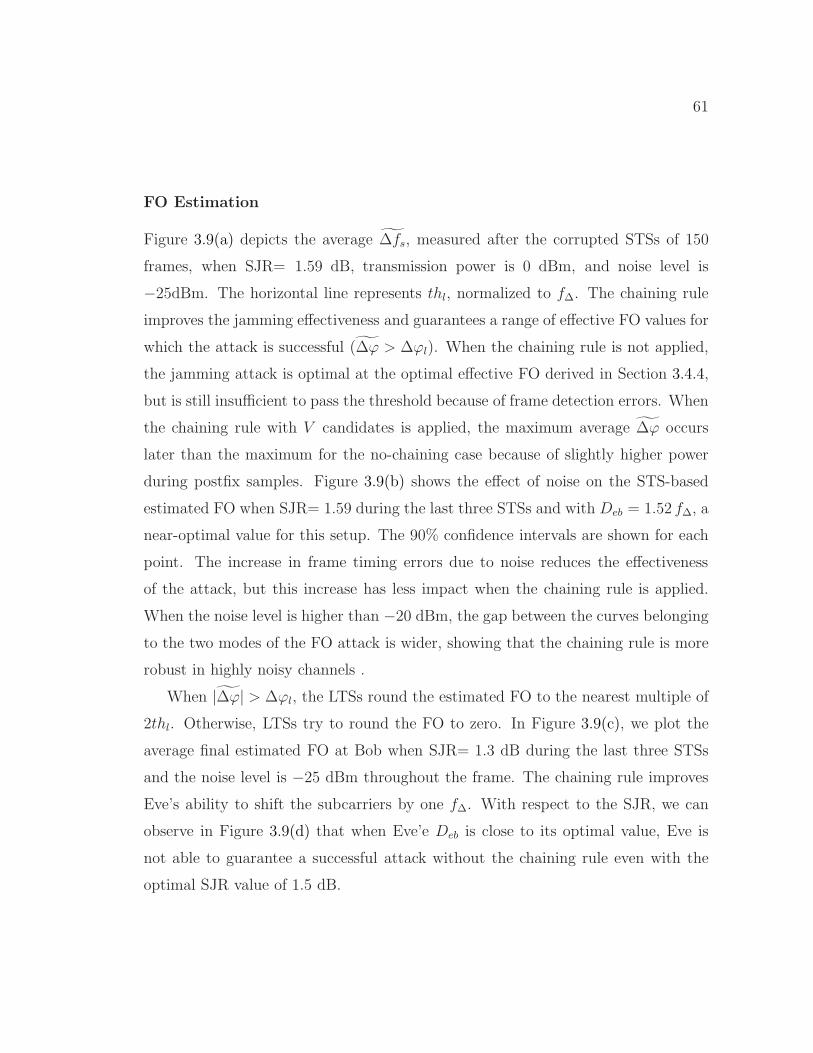
61
FO Estimation
Figure 3.9(a) depicts the average ∆fs, measured after the corrupted STSs of 150
frames, when SJR= 1.59 dB, transmission power is 0 dBm, and noise level is
−25dBm. The horizontal line represents thl, normalized to f∆. The chaining rule
improves the jamming effectiveness and guarantees a range of effective FO values for
which the attack is successful (∆ϕ > ∆ϕl). When the chaining rule is not applied,
the jamming attack is optimal at the optimal effective FO derived in Section 3.4.4,
but is still insufficient to pass the threshold because of frame detection errors. When
the chaining rule with V candidates is applied, the maximum average ∆ϕ occurs
later than the maximum for the no-chaining case because of slightly higher power
during postfix samples. Figure 3.9(b) shows the effect of noise on the STS-based
estimated FO when SJR= 1.59 during the last three STSs and with Deb = 1.52 f∆, a
near-optimal value for this setup. The 90% confidence intervals are shown for each
point. The increase in frame timing errors due to noise reduces the effectiveness
of the attack, but this increase has less impact when the chaining rule is applied.
When the noise level is higher than −20 dBm, the gap between the curves belonging
to the two modes of the FO attack is wider, showing that the chaining rule is more
robust in highly noisy channels .
When |∆ϕ| > ∆ϕl, the LTSs round the estimated FO to the nearest multiple of
2thl. Otherwise, LTSs try to round the FO to zero. In Figure 3.9(c), we plot the
average final estimated FO at Bob when SJR= 1.3 dB during the last three STSs
and the noise level is −25 dBm throughout the frame. The chaining rule improves
Eve’s ability to shift the subcarriers by one f∆. With respect to the SJR, we can
observe in Figure 3.9(d) that when Eve’e Deb is close to its optimal value, Eve is
not able to guarantee a successful attack without the chaining rule even with the
optimal SJR value of 1.5 dB.
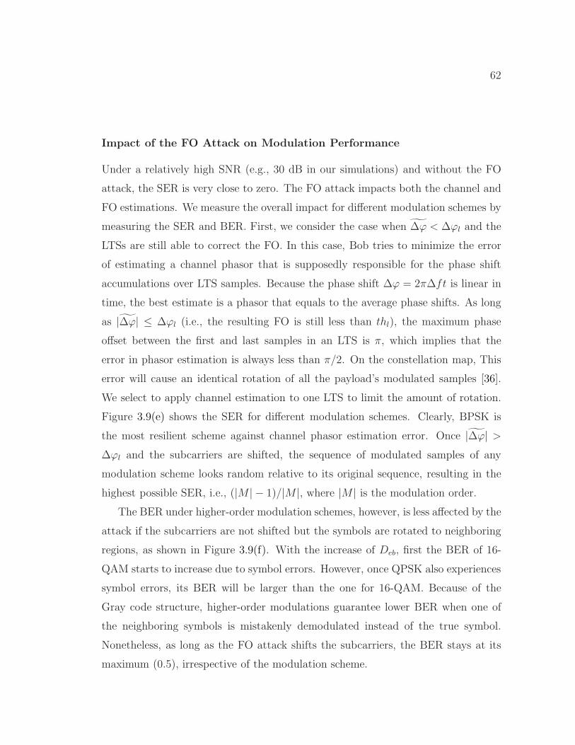
62
Impact of the FO Attack on Modulation Performance
Under a relatively high SNR (e.g., 30 dB in our simulations) and without the FO
attack, the SER is very close to zero. The FO attack impacts both the channel and
FO estimations. We measure the overall impact for different modulation schemes by
measuring the SER and BER. First, we consider the case when ∆ϕ < ∆ϕl and the
LTSs are still able to correct the FO. In this case, Bob tries to minimize the error
of estimating a channel phasor that is supposedly responsible for the phase shift
accumulations over LTS samples. Because the phase shift ∆ϕ = 2π∆ft is linear in
time, the best estimate is a phasor that equals to the average phase shifts. As long
as |∆ϕ| ≤ ∆ϕl (i.e., the resulting FO is still less than thl), the maximum phase
offset between the first and last samples in an LTS is π, which implies that the
error in phasor estimation is always less than π/2. On the constellation map, This
error will cause an identical rotation of all the payload’s modulated samples [36].
We select to apply channel estimation to one LTS to limit the amount of rotation.
Figure 3.9(e) shows the SER for different modulation schemes. Clearly, BPSK is
the most resilient scheme against channel phasor estimation error. Once |∆ϕ| >∆ϕl and the subcarriers are shifted, the sequence of modulated samples of any
modulation scheme looks random relative to its original sequence, resulting in the
highest possible SER, i.e., (|M | − 1)/|M |, where |M | is the modulation order.
The BER under higher-order modulation schemes, however, is less affected by the
attack if the subcarriers are not shifted but the symbols are rotated to neighboring
regions, as shown in Figure 3.9(f). With the increase of Deb, first the BER of 16-
QAM starts to increase due to symbol errors. However, once QPSK also experiences
symbol errors, its BER will be larger than the one for 16-QAM. Because of the
Gray code structure, higher-order modulations guarantee lower BER when one of
the neighboring symbols is mistakenly demodulated instead of the true symbol.
Nonetheless, as long as the FO attack shifts the subcarriers, the BER stays at its
maximum (0.5), irrespective of the modulation scheme.
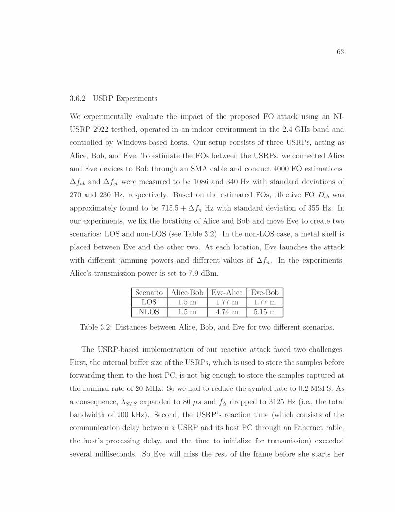
63
3.6.2 USRP Experiments
We experimentally evaluate the impact of the proposed FO attack using an NI-
USRP 2922 testbed, operated in an indoor environment in the 2.4 GHz band and
controlled by Windows-based hosts. Our setup consists of three USRPs, acting as
Alice, Bob, and Eve. To estimate the FOs between the USRPs, we connected Alice
and Eve devices to Bob through an SMA cable and conduct 4000 FO estimations.
∆fab and ∆feb were measured to be 1086 and 340 Hz with standard deviations of
270 and 230 Hz, respectively. Based on the estimated FOs, effective FO Deb was
approximately found to be 715.5 + ∆fn Hz with standard deviation of 355 Hz. In
our experiments, we fix the locations of Alice and Bob and move Eve to create two
scenarios: LOS and non-LOS (see Table 3.2). In the non-LOS case, a metal shelf is
placed between Eve and the other two. At each location, Eve launches the attack
with different jamming powers and different values of ∆fn. In the experiments,
Alice’s transmission power is set to 7.9 dBm.
Scenario Alice-Bob Eve-Alice Eve-BobLOS 1.5 m 1.77 m 1.77 mNLOS 1.5 m 4.74 m 5.15 m
Table 3.2: Distances between Alice, Bob, and Eve for two different scenarios.
The USRP-based implementation of our reactive attack faced two challenges.
First, the internal buffer size of the USRPs, which is used to store the samples before
forwarding them to the host PC, is not big enough to store the samples captured at
the nominal rate of 20 MHz. So we had to reduce the symbol rate to 0.2 MSPS. As
a consequence, λSTS expanded to 80 µs and f∆ dropped to 3125 Hz (i.e., the total
bandwidth of 200 kHz). Second, the USRP’s reaction time (which consists of the
communication delay between a USRP and its host PC through an Ethernet cable,
the host’s processing delay, and the time to initialize for transmission) exceeded
several milliseconds. So Eve will miss the rest of the frame before she starts her

64
jamming5. To overcome these challenges, we made the following modification in the
implementation. We let Alice send several back-to-back frames periodically with
a known period of T ms. Upon being triggered by a received power increase, Eve
captures 2 µs worth of the sequence. If a frame is detected, she assumes that the
next frame starts exactly T ms after the start of the this one. The host PC at
Eve then constructs a jamming signal based on the timing information of the first
detected frame and sends it to the USRP. After initialization, the USRP’s onboard
timer, which has nanosecond accuracy, waits for the remaining time before the next
frame arrival. Once the timer expires, the device starts jamming the preamble of
the new frame and other subsequent frames.
4000 5000 6000 7000
1000
2000
3000
4000
∆f n (Hz)
E[∆
fs](H
z)
6.15 dBm
6.85 dBm
7.95 dBm
8.9 dBm
10 dBm
(a) Effect of ∆fn on STS-basedFO estimation with differentjamming powers.
−6 −4 −2 0 2 4 6 80
50
100
150
200
Num
ber
of A
ttack
s
Estimated Frequency Offset (kHz)
After LTS−based estimation
Before LTS−based estimation
(b) Effect of LTS-based FO esti-
mation on ∆fs (∆fn = 7000 Hzand jamming power = 8.9 dBm).
Figure 3.10: USRP results: Performance of the FO attack in LOS scenario.
Figure 3.10(a) shows the average STS-based estimation of ∆fab in the LOS sce-
nario for different values of ∆fn and jamming powers. Because our USRPs do not
have stable oscillators and hence ∆fab varies with time, we represent the probable
value of ∆fab + f∆/2 by a shaded area whose height is twice the standard deviation
of ∆fab. Eve is able to shift the subcarriers by pushing ∆fs beyond the actual value
of ∆fab + f∆/2. The results show that even though Eve-Bob distance is larger than
5This is not the case for an off-the-shelf reactive jammer, which usually has an onboard processorand dedicated hardware. In addition, implementing a correlation-based reactive jammer on theUSRP’s FPGA can achieve a reaction time of 2.56 µs [40].
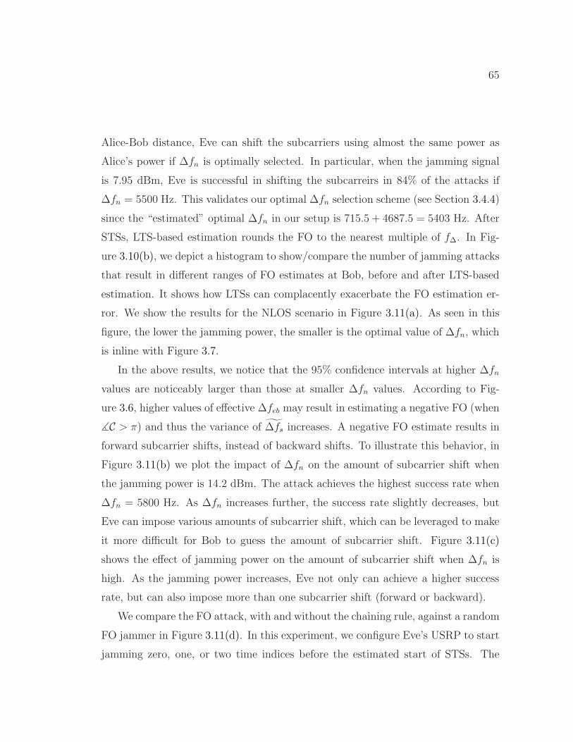
65
Alice-Bob distance, Eve can shift the subcarriers using almost the same power as
Alice’s power if ∆fn is optimally selected. In particular, when the jamming signal
is 7.95 dBm, Eve is successful in shifting the subcarreirs in 84% of the attacks if
∆fn = 5500 Hz. This validates our optimal ∆fn selection scheme (see Section 3.4.4)
since the “estimated” optimal ∆fn in our setup is 715.5 + 4687.5 = 5403 Hz. After
STSs, LTS-based estimation rounds the FO to the nearest multiple of f∆. In Fig-
ure 3.10(b), we depict a histogram to show/compare the number of jamming attacks
that result in different ranges of FO estimates at Bob, before and after LTS-based
estimation. It shows how LTSs can complacently exacerbate the FO estimation er-
ror. We show the results for the NLOS scenario in Figure 3.11(a). As seen in this
figure, the lower the jamming power, the smaller is the optimal value of ∆fn, which
is inline with Figure 3.7.
In the above results, we notice that the 95% confidence intervals at higher ∆fn
values are noticeably larger than those at smaller ∆fn values. According to Fig-
ure 3.6, higher values of effective ∆feb may result in estimating a negative FO (when
∡C > π) and thus the variance of ∆fs increases. A negative FO estimate results in
forward subcarrier shifts, instead of backward shifts. To illustrate this behavior, in
Figure 3.11(b) we plot the impact of ∆fn on the amount of subcarrier shift when
the jamming power is 14.2 dBm. The attack achieves the highest success rate when
∆fn = 5800 Hz. As ∆fn increases further, the success rate slightly decreases, but
Eve can impose various amounts of subcarrier shift, which can be leveraged to make
it more difficult for Bob to guess the amount of subcarrier shift. Figure 3.11(c)
shows the effect of jamming power on the amount of subcarrier shift when ∆fn is
high. As the jamming power increases, Eve not only can achieve a higher success
rate, but can also impose more than one subcarrier shift (forward or backward).
We compare the FO attack, with and without the chaining rule, against a random
FO jammer in Figure 3.11(d). In this experiment, we configure Eve’s USRP to start
jamming zero, one, or two time indices before the estimated start of STSs. The

66
4000 5000 6000 7000
1000
2000
3000
4000
∆fn (Hz)
E[∆
fs](H
z)
12.1 dBm
13.1 dBm
14.2 dBm
14.9 dBm
16 dBm
(a) Effect of ∆fn on STS-basedFO estimation with different jam-ming powers.
4000 5000 6000 70000
20
40
60
80
100
∆fn (Hz)
% o
f Atta
cks
2 shifts F/W
1 shift F/W
No shift
1 shift B/W
2 shifts B/W
(b) Effect of ∆fn on the amountof subcarrier shifts (jammingpower = 14.2 dBm).
12 13 14 15 160
20
40
60
80
100
Jamming Power (dBm)
% o
f Atta
cks
2 shifts F/W
1 shift F/W
No shift
1 shift B/W
2 shifts B/W
(c) Effect of jamming power onthe amount of subcarrier shifts(∆fn = 7000 Hz).
11 12 13 14 15 160
1000
2000
3000
4000
5000
Jamming Power (dBm)
E[∆
f s](H
z)
w/ chaining
w/o chaining
Random FO jammer
(d) Performance of different vari-ants of the FO attack vs. jam-ming power (∆fn = 5700Hz).
Figure 3.11: USRP results: Performance of the FO attack in the NLOS scenario.Alice’s signal power is 7.9 dBm.
random FO jammer generates uniform white noise. The results confirm that the
chaining rule strengthens the attack while random jamming cannot manipulate ∆fs
and overcome the LTSs even with high jamming power.
Finally, we launch the FO attack during the transmission of a packetized image.
Specifically, Eve attacks 24 packets in the middle of the transmission of 44 QPSK-
modulated 720-byte-long packets that represent the image in Figure 3.12(a). In
Figure 3.12(b), we show the received image. The parts that experience FO jamming
are completely destroyed.

67
3.6.3 Comparison to Existing Jamming Attacks
Vulnerabilities of wireless protocols and Denial-of-service (DoS) attacks have been
studied in the literature since the early 2000s. DoS attacks can be applied at either
MAC or PHY-layer. MAC layer attacks usually take the form of malicious packet
insertion, whereas RF jamming is a form of PHY-layer attack.
RF Jamming techniques are categorized into constant, deceptive, random, re-
active, and short noise-based (narrow-band) intelligent jamming methods [30, 41].
Constant, deceptive, and random jamming models achieve a high level of DoS by
excessively transmitting over the channel, but exhibit poor energy efficiency and
high detection probability [41]. On the other hand, energy-efficient reactive jam-
ming attacks select and target a (part of a) packet based on traffic analysis, protocol
semantics, or publicity of some fields [20, 21, 29, 30, 33, 40]. These attacks may fail
to significantly corrupt ongoing transmissions if, for example, channel hopping, ran-
domization, and coding are used to hide the transmission features.
The efficiency of reactive jamming is assessed by the effort needed to drop a
packet. In [29], jamming efficiency is defined as the ratio of communication effort
to jamming effort. The authors demonstrated the jamming efficiency of 50 ∼ 500 in
802.11a by jamming an OFDM symbol. Using a high duty-cycle jammer, Gummadi
et al. [33] could disrupt a link when the jamming power is 1000 weaker than the
signal power by targeting timing recovery, dynamic range selection (AGC), and
header processing. The authors in [19] observed that 22 µs of jamming is sufficient
to make a frame undecodable. In comparison, our FO attack can achieve a jamming
efficiency of 136 ∼ 1400 in 802.11a and defeat any ECC by jamming for only 2.8 µs.
Jamming OFDM systems is of particular interest due to their widespread use in
modern systems. Simple barrage jamming targets the entire spectrum/tones and
corrupts more bits than the more power efficient but less destructive partial band,
single- and multi-tone jamming [22, 42]. Asynchronous off-tone jamming attacks
exploit the uncompensated FO between Eve and Bob to transmit one or multiple
68
subcarriers that will be received between some of the data subcarriers [22]. This
creates significant ICI for those subcarriers. Though energy-efficient, these attacks
cannot achieve 50% BER. Furthermore, because coding and interleaving are em-
ployed in the 802.11 systems for robustness against narrow-band interference, Bob
may still be able to recover the frame. Several pilot jamming attacks were proposed
in [22, 32] in order to distort channel estimation. In contrast, our proposed attack
lasts for less than the duration of a pilot symbol jamming and corrupts the channel
estimation without jamming pilots. Jamming against timing acquisition in OFDM
systems and some countermeasures were discussed in [20, 34, 35]. However, OFDM
systems are more sensitive to FO than timing errors. This vulnerability was first
revealed in [21]. The structured but essentially random jamming scheme in [21],
however, does not provide any performance guarantee and may have higher jam-
ming effort than ours. Interested readers are referred to [39, 43] for more details
about jamming attacks against OFDM systems.
3.7 Defense Strategies
Alice and Bob may work cooperatively or independently to mitigate the previously
presented FO attack. For example, they may prevent accurate estimation of ∆fab at
Eve by transmitting Tx-based friendly jamming. This, however, requires additional
antennas. Bob may also use the power-spectral density of the captured signal after
LTSs to identify the missing subcarriers, and thus determine the overall subcarrier
shift. This technique, however, fails if Eve transmits only one or two bogus sub-
carriers to replace missing subcarriers. Assuming that Bob is not equipped with
additional antennas, in this chapter we propose three preliminary approaches for
mitigating the FO attack. In Chapter 6, we further propose a mitigation technique
by altering the default preamble signal in a way that Bob is still able to perform
preamble functions as normal. However, Eve will no longer have the knowledge of
the preamble samples ui because the preamble is no longer public. Hence, she will

69
(a) Transmitted image (b) Received image
Figure 3.12: Applying the FO attack on a sequence of frames belonging to an image.
not be able to design its jamming samples ri based on ui’s and account for unknown
channel coefficient and timing errors. Analysing and evaluating these strategies are
beyond the scope of this dissertation, and will be addressed in future research.
1) Randomizing FO Sequences (Sequence Hopping): Because of the re-
dundancy in the STSs, Bob can choose any pair of the ten consecutive STSs, to
perform FO estimation. Furthermore, due to the maximum FO requirement for
802.11 devices (212 kHz = 1.3568 ths for devices operating in the 5 GHz band and
125 kHz = 0.8 ths for devices in the 2.4 GHz band [24]), the two autocorrelation
windows do not necessarily need to be contiguous. In fact, the two windows can be
two or four STSs apart (i.e., each sample is three or five STSs away from its dual) in
the 5 GHz and 2.4 GHz bands, respectively. This means that Bob has the flexibility
to randomly hop to any pair of STSs for FO estimation, given that the STSs in this
pair are not more than two or four STSs apart, depending on the frequency band.
Even if Bob selects an STS that is corrupted by a jamming signal together with a
jamming-free one, he is still able to estimate the same FO as if two jamming-free
sequences are selected [36]. To implement sequence hopping, Bob can record the
received signal (the ten STSs) while he is in the process of detecting the start of the
frame. Once the frame has been detected, Bob randomly chooses two STSs for FO
estimation, while satisfying the maximum STS-distance constraint.
2) Preamble Obfuscation: Preamble obfuscation aims at making the timing
70
or FO features hard to extract by Eve. We provide one simple example for timing
extraction. Alice can obfuscate the preamble by adding artificial noise that is only
known to Bob. He, on the other side, modifies the denominator in (2.2) to account
for the power of the artificial noise during a certain section of the received signal.
For example, a signal identical to the first half of an STS may be added to the
first half of the second STS in the preamble. So, Bob can still detect the frame by
doubling the denominator in (2.2), but the increased power at Eve would decrease
the value ofM(n) through (2.2) for the first L/2 samples. Hence, M will be in the
second half, making the chaining rule fail because Eve does not include the actual
start time in the V = log2 L start times.
3) STS Bypassing: Bob can simply disable the STS-based FO estimation
mechanism to dodge the FO attack. However, he still has to meet the requirement
for coarse FO estimation, i.e., unambiguous phase estimation (see Section 3.2).
Under BPSK modulation, which is typically used to transmit the PHY header,
Bob can tolerate channel estimation errors due to an FO estimation error of up to
15 kHz [13]. Hence, Bob can divide the range of possible FO values into several
equal-size frequency bins, each of 30 kHz bandwidth. He can then try each of
the possible bins and compensate for its center frequency before applying LTS-
based FO estimation. The center frequency that results in the minimum MSE in
channel estimation can be considered as ∆fs. Bob may also suppress both STS-
and LTS-based FO estimation, and instead rely on pilot subcarriers for FO and
channel estimation. This approach, however, often gives rise to ICI because adjacent
subcarriers interfere with the pilot subcarriers (which even are not yet channel-
equalized) and the FO estimation will be erroneous.
3.8 Summary
We demonstrated the vulnerability of OFDM systems against a highly disruptive
but efficient-efficient DoS attack. This attack succeeds even when the PHY frame
71
is shielded by interleaving and channel coding. The attack focuses on the frequency
offset (FO) estimation process, and is channel-independent and robust to time-
synchronization errors at Eve through applying the proposed pairing and chaining
rules. Through this attack, a reactive jammer exploits and targets a small portion of
the publicly known preamble used for FO estimation. The attack lasts for less than
the duration of an OFDM symbol, i.e., less than 1% of a typical frame duration, and
is at least 30% more efficient than previously reported attacks. Though short-lived,
the attack results in a shift in subcarrier indices and the maximum possible BER
(50%) even when the jamming signal at Bob is∼ 1.4 times weaker than Alice’s signal.
We verified via simulations and USRP experimentation. The simulation results show
that different modulation schemes are equally susceptible if the FO attack can shift
the subcarrier indices, and higher modulation orders are more affected when the
attack impacts only the channel estimation. Finally, we sketched several possible
mitigation approaches, whose detailed analysis and evaluation are left for future.

72
CHAPTER 4
Friendly Jamming in Multi-link Scenarios
4.1 Introduction
Information theoretic secrecy [44, 45] at the PHY layer is a lightweight approach
that aims at preventing Eve from decoding a plaintext frame or extracting SCI from
unencrypted headers. Alice and its legitimate receiver (Bob) are guaranteed secret
communications if the Alice-Bob channel is better than Alice-Eve channel. In [44],
the notion of secrecy capacity was introduced as the maximum rate at which Alice
can securely transmit information to Bob. This rate is the difference between the
mutual information between Alice and Bob, to that between Alice and Eve.
Non-zero secrecy capacity is not always possible. For example, if Eve is closer to
Alice than Bob, then the Alice-Eve channel may be better than the Alice-Bob chan-
nel, resulting in zero secrecy capacity [44]. Friendly jamming (FJ), proposed in the
pioneering work of Goel and Negi [23], can be used to degrade the Alice-Eve channel
without harming Bob’s reception. Essentially, a FJ signal is a randomly generated
artificial noise. To nullify the FJ signal at Bob, the authors in [23] considered the
case when Alice has multiple antennas. Alternatively, a bank of relay nodes can be
utilized to transmit the artificial noise in the null space of the Alice-Bob channel.
4.1.1 Existing FJ-based Schemes for Multi-link Scenarios
Although FJ-based PHY-layer security has been extensively considered for single-
link scenarios, only a few papers studied the problem in multi-link scenarios. Re-
search efforts on secret communications in a multi-link network can be classified into

73
two broad categories: Large-scale [46–48] and small-scale wireless networks [49,50].
Considering a large-scale wireless network consisting of n nodes, the authors in [46]
derived the per-node asymptotic secrecy capacity. They also proposed to use “Rx-
based FJ”, whereby legitimate full-duplex receivers are able to cancel the self-
interference resulting from their generation of FJ signals. For the case of inde-
pendent eavesdroppers, it was shown that a per-node secrecy capacity of Θ( 1√n)
is achievable, which is the same per-node capacity without secrecy considerations.
These results imply that the per-node secrecy capacity is not affected by the pres-
ence of eavesdroppers. However, placing the FJ devices at the same locations of the
communicating nodes may not be optimal from an energy consumption perspective.
The interference of Rx-based FJ on other receivers was also not considered in [46].
The authors in [48] explored allowing a fraction of transmitters to cooperatively
send their signals to their receivers through relay nodes, i.e., two-hop communica-
tions. The idea is based on the work in [51]; wherein, for each Alice-Bob pair, a
relay node with “good” channels to Alice and Bob is selected. Relay nodes with
“bad” channels to the selected relay or to Bob are used to produce FJ signals to
confuse passive eavesdroppers. Instead of generating FJ signals, simultaneous trans-
missions are exploited in [48] to create high interference at the eavesdroppers. In
this sense, the messages of other Alice-Bob pairs are utilized as FJ signals. Secrecy
is guaranteed only as n tends to infinity. The results of large-scale wireless net-
work, however, may not be always applicable to small-scale networks that can have
irregular topologies.
Secure minimum-energy routing with the aid of FJ was investigated in [49,50] for
a small-scale network. The objective is to compute a minimum-energy path subject
to constraints on the end-to-end communication secrecy and the throughput over
the path. The authors proposed a scheme to assign FJ power required to secure in-
dividual links. Each link was studied independently, assuming that it can be secured
by its own set of FJ devices, and there is a discrete set of eavesdropping locations,

74
each with a given probability of eavesdropping in that location. The secure routing
problem was reduced to finding a path with the minimum total information and
FJ power. These works, although applicable to small-scale networks, do not jointly
consider the optimal placement and power allocation of the FJ devices. Moreover,
they do not exploit the FJ devices associated with a given link to help in providing
secrecy for another link, which can reduce the total jamming power. Finally, they
assume that the FJ signals are nullified at legitimate receivers, but the conditions
needed to ensure such nullification are not incorporated in the formulation. This
undermines the applicability of their designs.
4.1.2 Main Contributions and Chapter Organization
The example in Figure 4.1 illustrates the importance of optimizing the placement
of the FJ devices. Eve 1 and 2 are the most vulnerable eavesdroppers due to their
proximity to Alice. If the FJ devices are placed near Bob (e.g., Rx-based jamming),
they would need high power to deafen Eve 1 and 2. The FJ device would consume
less power to deafen Eve 1 and 2 if they are moved to the potentially optimal location
shown in Figure 4.1. Note that if the FJ devices are instead moved to the centroid of
the eavesdropping locations or near Alice (e.g., Tx-based jamming), they will have
a larger distances to Eve 1 and 2 and consume larger amount of power to deafen
them.
In this chapter, we consider the problem of placing FJ devices in a small-scale
multi-link wireless network, e.g., peer-to-peer (P2P) or multihop, and address the
aforementioned limitations of existing PHY-layer solutions. Our contributions are
summarized as follows:
� We first consider a per-link strategy and formulate an optimization problem
that aims at jointly optimizing the power allocation and placement of the FJ
devices for a given link under secrecy constraint. We show that our proposed
scheme reduces power consumption by 55%–99% compared to the case in which
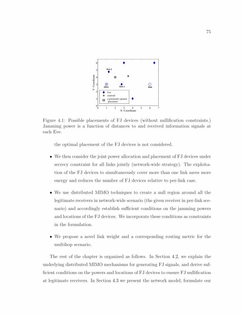
75
0 1 2 3 4 5 6 70
1
2
3
4
5
6
Alice Bob Eve 1
Eve 2
X−Coordinate
Y−
Coo
rdin
ate
Evecentroid
a potentially optimal placement
Figure 4.1: Possible placements of FJ devices (without nullification constraints.)Jamming power is a function of distances to and received information signals ateach Eve.
the optimal placement of the FJ devices is not considered.
� We then consider the joint power allocation and placement of FJ devices under
secrecy constraint for all links jointly (network-wide strategy). The exploita-
tion of the FJ devices to simultaneously cover more than one link saves more
energy and reduces the number of FJ devices relative to per-link case.
� We use distributed MIMO techniques to create a null region around all the
legitimate receivers in network-wide scenario (the given receiver in per-link sce-
nario) and accordingly establish sufficient conditions on the jamming powers
and locations of the FJ devices. We incorporate these conditions as constraints
in the formulation.
� We propose a novel link weight and a corresponding routing metric for the
multihop scenario.
The rest of the chapter is organized as follows. In Section 4.2, we explain the
underlying distributed MIMO mechanisms for generating FJ signals, and derive suf-
ficient conditions on the powers and locations of FJ devices to ensure FJ nullification
at legitimate receivers. In Section 4.3 we present the network model, formulate our

76
problem, prove that it is an NP-hard signomial programming problem, and then
approximate it by a geometric programming problem, which can further be convex-
ified. In Section 4.4 we propose a novel link weight for the secure routing problem.
Section 4.5 provides the simulation results. Finally, Section 4.6 concludes the chap-
ter.
4.2 Distributed MIMO for FJ Nullification
If the FJ signals are to be generated by the same MIMO node (e.g., Alice), then the
phases of these signals can be easily controlled to provide the desired nullification. A
set of FJ signals can add destructively and nullify each other at an intended receiver
if these signals, each of which traverses a different channel, are received out-of-phase
and sum up to zero. To achieve this, techniques such as zero-forcing beamforming are
employed to determine the phase and amplitude of each FJ signal at the transmit
antennas. However, in general, FJ signals may be produced by different devices
that do not share a reference clock and so are not synchronous. Hence, the signals
transmitted from distributed FJ nodes may experience unknown random delays. In
this section, we explain how we synchronize FJ devices, each equipped with a single
antenna, and establish the sufficient conditions on the jamming signals to ensure
nullification of FJ signals at all legitimate receivers.
4.2.1 Synchronization of FJ Devices
To enable synchronized FJ devices, we exploit SourceSync’s synchronization protocol
proposed and empirically demonstrated in [38] for OFDM systems. According to this
method, a set of distributed cooperative transmitters choose a leader, who initiates
the synchronization process by transmitting an OFDM-based sync header. Using
the phase offsets measured across different subcarriers, each cooperating transmitter
can accurately estimate the arrival time of the sync header. Based on the estimated

77
RTT between each transmitter and the leader, and the switching time from Rx mode
to Tx, each transmitter synchronizes in time with the leader. Finally, considering
the propagation delay of the transmitters to the receiver, each transmitter selects
a transmission time so as to synchronize the arrival of all the transmissions at the
receiver.
4.2.2 Nullification of FJ Signals
Assuming that the distributed FJ nodes have been synchronized, the ampli-
tudes/phases of their signals must be adjusted to cancel out at the legitimate re-
ceivers. Consider M legitimate receivers and N FJ nodes. The channel is charac-
terized by an M ×N channel matrix H = [hij ], where hij is the channel coefficient
between receiver i and transmitter j. By setting N = M + 1, we can guarantee
a nonempty null space for the channel matrix H [23]. Let y be an M-by-1 vector
that represents only the received FJ signals at the M receivers, let x be an N -by-1
vector that represents the transmitted signals from the N FJ antennas, and let F
represent the N -by-1 precoding vector (precoder) of the FJ signal.
At any time instant (time index is dropped for simplicity) and ignoring the effect
of noise, we have:
y = Hx = HFm (4.1)
where m denotes a random complex scalar at the current time and ||m||2 = 1. The
Singular Value Decomposition (SVD) of H can be obtained as
H = UM×MΣM×NV†N×N. (4.2)
Thus, y can be expressed as:
y = UΣV†x. (4.3)
If the jamming precoder F lies in the null space of H, then y = Hx = 0. In

78
our design, we select F as the rightmost column of the matrix V, i.e., the kernel of
H. For a given total budget on the jamming power and a given m, the precoder
F determines the phase of each of the FJ signals and implies some dependencies
between their jamming powers so that they add up destructively at the legitimate
receivers. Let Pj = ||xj||2 = ||Fj||2 be the jamming power of the jth FJ device. We
explicitly derive these dependencies by solving∑N
j=1 hijxj = 0, ∀i = 1, . . . ,M . It
turns out that each jamming power must be a linear function of P1 as follows:
Pj = ωjP1, ∀j = 2, . . . , N (4.4)
where ωj is the scalar ratio between Pj and P1.
4.3 PHY-layer Security for Multi-link Networks
4.3.1 Network Model and Problem Formulation
We consider a static multi-link network, consisting of an arbitrary number of legit-
imate nodes, each equipped with an omni-directional antenna. These nodes form a
set of links L. Each link l consists of a source (Alice) and a destination (Bob). This
general multi-link network model accommodates both P2P and multihop scenarios.
For the P2P scenario, L consists of several independent single-hop links, connecting
different Alice-Bob pairs. In the multihop case, L contains specific links that form
several paths between various pairs of nodes. Along with the set L, there is a finite
set E of eavesdropping locations and a set J of FJ nodes. We adopt a 2-D discrete
model for the points in E [49, 50]. The probability that an eavesdropper is in loca-
tion e ∈ E is denoted by pe. Even though this model assumes some (probabilistic)
knowledge of the eavesdroppers’ locations, it can represent numerous scenarios by
adjusting the number of locations and the probabilities assigned to them.
The number of FJ devices can be less than or greater than |E|. In here, however,
we only consider the case when |E| > |J |, since the solution for the other cases
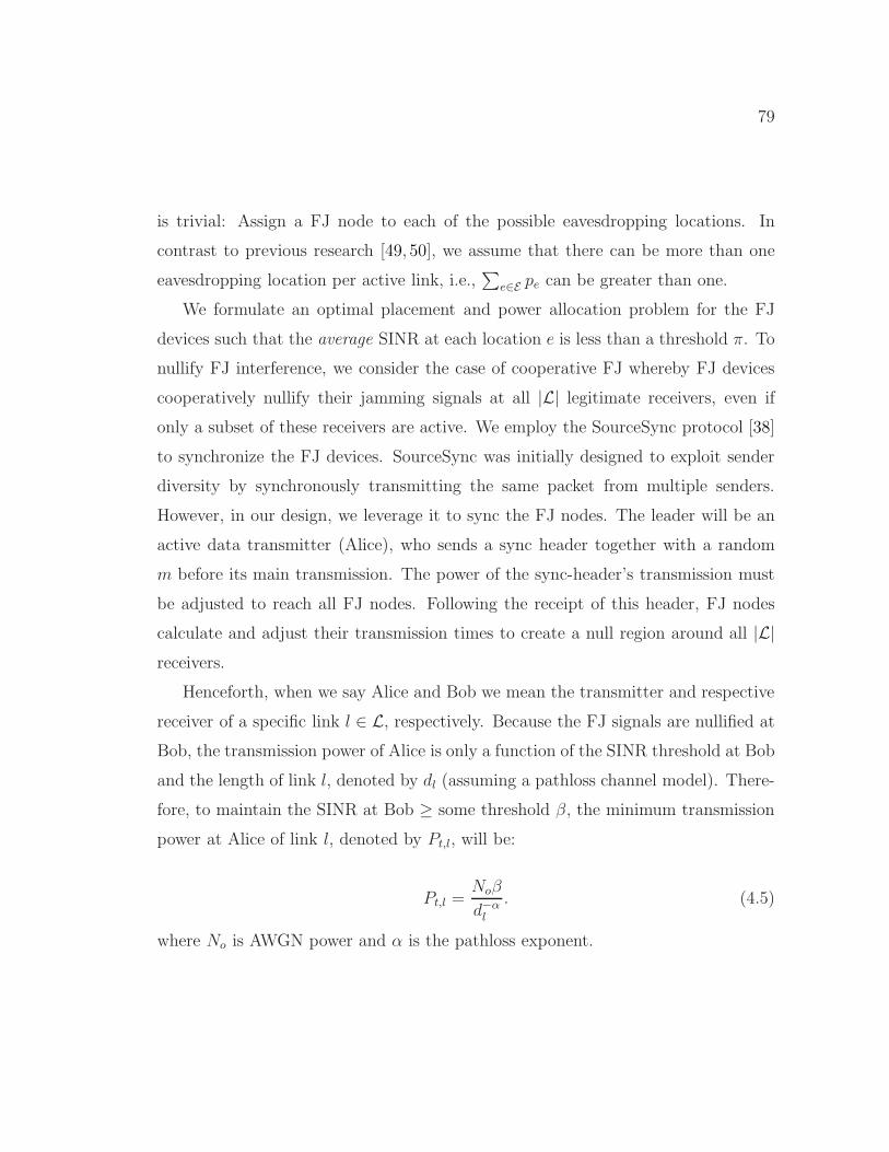
79
is trivial: Assign a FJ node to each of the possible eavesdropping locations. In
contrast to previous research [49, 50], we assume that there can be more than one
eavesdropping location per active link, i.e.,∑
e∈E pe can be greater than one.
We formulate an optimal placement and power allocation problem for the FJ
devices such that the average SINR at each location e is less than a threshold π. To
nullify FJ interference, we consider the case of cooperative FJ whereby FJ devices
cooperatively nullify their jamming signals at all |L| legitimate receivers, even if
only a subset of these receivers are active. We employ the SourceSync protocol [38]
to synchronize the FJ devices. SourceSync was initially designed to exploit sender
diversity by synchronously transmitting the same packet from multiple senders.
However, in our design, we leverage it to sync the FJ nodes. The leader will be an
active data transmitter (Alice), who sends a sync header together with a random
m before its main transmission. The power of the sync-header’s transmission must
be adjusted to reach all FJ nodes. Following the receipt of this header, FJ nodes
calculate and adjust their transmission times to create a null region around all |L|receivers.
Henceforth, when we say Alice and Bob we mean the transmitter and respective
receiver of a specific link l ∈ L, respectively. Because the FJ signals are nullified at
Bob, the transmission power of Alice is only a function of the SINR threshold at Bob
and the length of link l, denoted by dl (assuming a pathloss channel model). There-
fore, to maintain the SINR at Bob ≥ some threshold β, the minimum transmission
power at Alice of link l, denoted by Pt,l, will be:
Pt,l =Noβ
d−αl
. (4.5)
where No is AWGN power and α is the pathloss exponent.

80
For the case of cooperative jamming, the SINR at Bob (SINRb) is given by:
SINRb =Pt,ld
−αl
No. (4.6)
The optimization problem can now be stated as follows:
P1: minimize{xj ,yj ,Pj ∀j∈J}
∑
j∈JPj
subject to C1: peSINRe ≤ π, ∀e ∈ E , ∀l ∈ L
C2:
|J |∑
j=1
hijxj = 0, i = 1, . . . , |L|
(4.7)
where (xj , yj) are the Cartesian coordinates of FJ node j. Constraints C1 and
C2 represent the secrecy and nullification constraints, respectively. When link l is
active, the SINR at eavesdropper e (SINRe) is given by:
SINRe =Pt,ld
−αae,l
No +∑
j∈J Pjd−αje
(4.8)
where dae,l is the distance between Alice (of link l) and eavesdropping location e,
and dje is the distance between the FJ node j and eavesdropper e. Note that j, e,
and hence dje are not associated with a specific link l.
We propose two schemes based on formulation P1: per-link and network-wide
schemes. For the per-link scheme, the problem is solved independently for each link.
In this case, we have |L| independent problems. For each of these problems, the
secrecy and nullification constraints are considered only for a specific link l, i.e.,
|L| = 1. To ensure a nonempty nullspace for the channel matrix H, |J | has to be
greater than |L|. This implies that in the per-link scheme, J in each problem must
contain a minimum of two FJ nodes. Hence, we need at least 2|L| FJ nodes to secureall links. For the network-wide scheme, all links and FJ devices are simultaneously
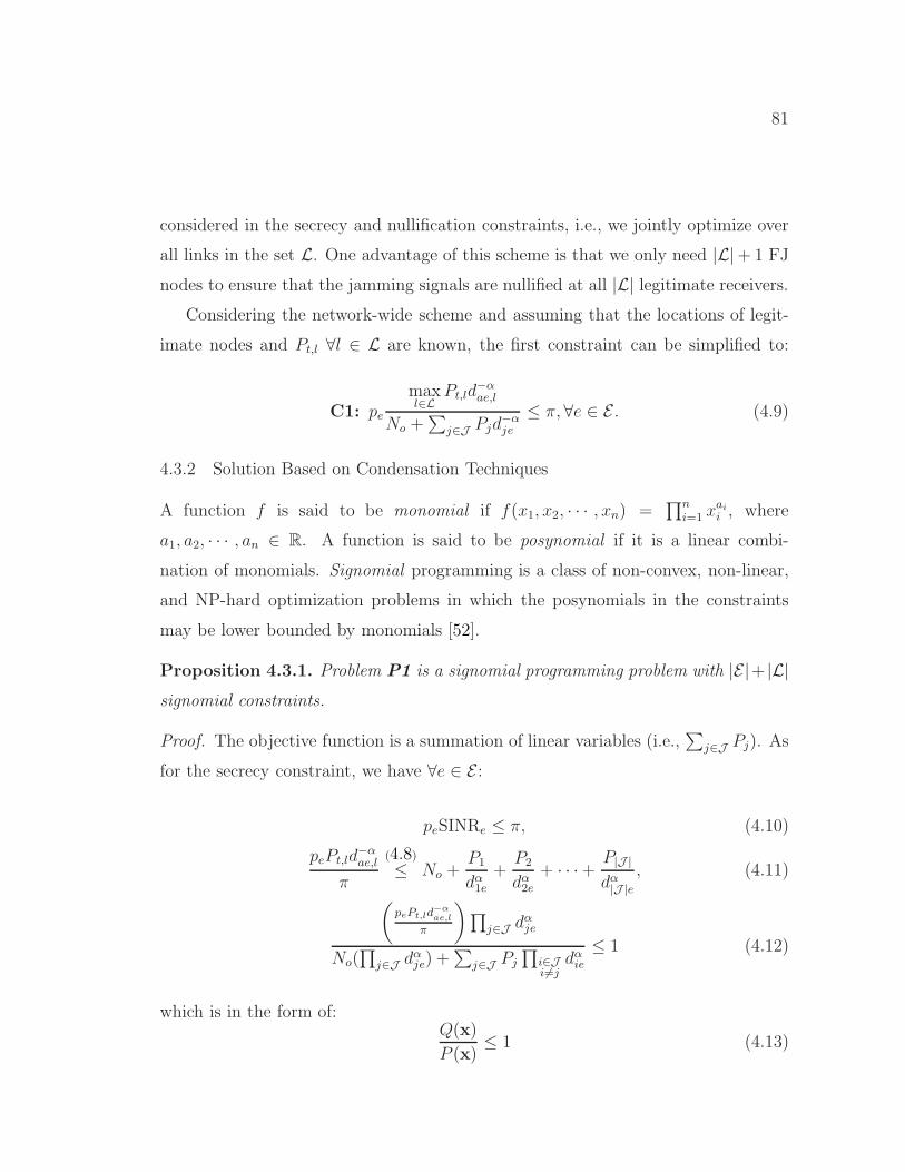
81
considered in the secrecy and nullification constraints, i.e., we jointly optimize over
all links in the set L. One advantage of this scheme is that we only need |L|+ 1 FJ
nodes to ensure that the jamming signals are nullified at all |L| legitimate receivers.
Considering the network-wide scheme and assuming that the locations of legit-
imate nodes and Pt,l ∀l ∈ L are known, the first constraint can be simplified to:
C1: pe
maxl∈L
Pt,ld−αae,l
No +∑
j∈J Pjd−αje
≤ π, ∀e ∈ E . (4.9)
4.3.2 Solution Based on Condensation Techniques
A function f is said to be monomial if f(x1, x2, · · · , xn) =∏n
i=1 xaii , where
a1, a2, · · · , an ∈ R. A function is said to be posynomial if it is a linear combi-
nation of monomials. Signomial programming is a class of non-convex, non-linear,
and NP-hard optimization problems in which the posynomials in the constraints
may be lower bounded by monomials [52].
Proposition 4.3.1. Problem P1 is a signomial programming problem with |E|+ |L|signomial constraints.
Proof. The objective function is a summation of linear variables (i.e.,∑
j∈J Pj). As
for the secrecy constraint, we have ∀e ∈ E :
peSINRe ≤ π, (4.10)
pePt,ld−αae,l
π
(4.8)≤ No +
P1
dα1e+
P2
dα2e+ · · ·+ P|J |
dα|J |e, (4.11)
(pePt,ld
−αae,l
π
)∏j∈J dαje
No(∏
j∈J dαje) +∑
j∈J Pj
∏i∈Ji 6=j
dαie≤ 1 (4.12)
which is in the form of:Q(x)
P (x)≤ 1 (4.13)

82
where Q(x) and P (x) are monomial and posynomial, respectively.
The same analysis can be applied to the nullification constraint to show that it
also represents |L| signomial constraints. It follows that our formulation belongs to
the category of signomial programming [52, 53]. �
Signomial problems cannot be transformed to convex problems. However, by
using condensation techniques [54], we can approximate any multi-term posynomial
P (x) by a monomial and transform P1 into the standard geometric programming
form (i.e., Q(x) ≤ P (x), where P (x) is the approximated monomial of the posyn-
omial P (x)). It can be shown that optimal solution of the condensed problem is
a feasible (but not necessarily optimal) solution for P1 and so upper-bounds its
optimal solution.
The original problem can then be heuristically solved by iteratively updating
the parameters of the condensed problem. For each iteration, we use the optimal
solution of the previous condensed problem to update the approximation parameters,
and so on until we converge to the optimal solution of P1. Because the problem is
non-convex, the algorithm may get stuck in a local minima, a case that is left for
future work.
4.4 Secrecy-aware Routing Problem
Considering the per-link scheme to jointly optimize the transmission powers and
locations of the FJ devices in the multihop scenario, we propose to use the total FJ
power needed to secure each link as the link weight. Thus, for link l ∈ L, its weightis:
w(l) =∑
j∈JPj . (4.14)
By securing each hop, end-to-end secrecy is achieved [47,48]. At the same time,
the quality of service is ensured by having the SINR at each end of a link lower-
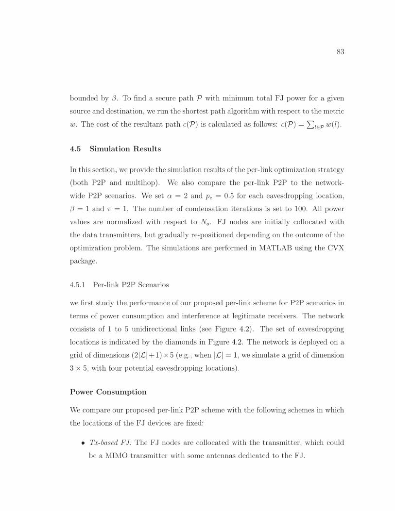
83
bounded by β. To find a secure path P with minimum total FJ power for a given
source and destination, we run the shortest path algorithm with respect to the metric
w. The cost of the resultant path c(P) is calculated as follows: c(P) =∑
l∈P w(l).
4.5 Simulation Results
In this section, we provide the simulation results of the per-link optimization strategy
(both P2P and multihop). We also compare the per-link P2P to the network-
wide P2P scenarios. We set α = 2 and pe = 0.5 for each eavesdropping location,
β = 1 and π = 1. The number of condensation iterations is set to 100. All power
values are normalized with respect to No. FJ nodes are initially collocated with
the data transmitters, but gradually re-positioned depending on the outcome of the
optimization problem. The simulations are performed in MATLAB using the CVX
package.
4.5.1 Per-link P2P Scenarios
we first study the performance of our proposed per-link scheme for P2P scenarios in
terms of power consumption and interference at legitimate receivers. The network
consists of 1 to 5 unidirectional links (see Figure 4.2). The set of eavesdropping
locations is indicated by the diamonds in Figure 4.2. The network is deployed on a
grid of dimensions (2|L|+1)×5 (e.g., when |L| = 1, we simulate a grid of dimension
3× 5, with four potential eavesdropping locations).
Power Consumption
We compare our proposed per-link P2P scheme with the following schemes in which
the locations of the FJ devices are fixed:
� Tx-based FJ: The FJ nodes are collocated with the transmitter, which could
be a MIMO transmitter with some antennas dedicated to the FJ.

84
0 2 4 6 80
5
10
15
201 2
3 4
5 6
7 8
9 10
1
2
3
4
5
6
7
8
9
10
11
12
13
14
15
16
X−Coordinate
Y−
Coo
rdin
ate
Figure 4.2: Network topology for thecase of five P2P links. Hollow cir-cles, crossed circles, and diamonds repre-sent receivers, transmitters, and poten-tial eavesdropping locations.
1 2 3 4 510
0
101
102
103
104
Number of Links (|L|)
Tot
al J
amm
ing
Pow
er (
norm
aliz
ed)
proposed schemeTx−based−FJcentroidRx−based−FJ
Figure 4.3: Total jamming power vs.number of links for the P2P scenario(per-link).
� Rx-based FJ: The FJ nodes are placed at full-duplex receivers with perfect
self-interference cancellation.
� Centroid: The FJ nodes are placed at the centroid of all potential eavesdrop-
ping locations.
Collectively, we refer to the above three schemes by fixed-placement schemes. As
shown in Figure 4.3, our proposed per-link P2P scheme outperforms the fixed-
placement schemes achieving 55%–99% reduction in power consumption. The cen-
troid scheme is the worst in terms of power consumption because FJ nodes are
located far away from data transmitters and need to increase their powers to cover
eavesdropping points around data transmitters.
To illustrate the outcome of the proposed per-link P2P case, we consider a net-
work of one link (i.e., |L| = 1), as shown in Figure 4.4. Numbers by each node
in this figure represent the amount of interference caused by the FJ nodes on that
node. In Figure 4.5, we show the change in the jamming power for each of the FJ
nodes in Figure 4.4 along with their total jamming power as a function of the opti-

85
1 2 3 4 5 6 71
1.5
2
2.5
3
3.5
4
4.5
5
1
2
3
4
X−Coordinate
Y−
Coo
rdin
ate
Bob1.8312
Alice
1.8463
FJ1
2.7 × 10⁻⁶
FJ2
2.0374
2.0227
Figure 4.4: Outcome of the proposedper-link scheme for the one-link case.The hollow, crossed, and solid circlesrepresent the locations of Bob, Alice,and the FJ nodes, respectively.
0 20 40 60 80 1000
2
4
6
8
10
12
Iteration Index
Jam
min
g P
ower
(no
rmal
ized
)
total jamming powerP
j1
Pj2
Figure 4.5: Jamming power of each FJnode along with total jamming power vs.approximation (iteration) index for theexample in Figure 4.4.
mization iteration (see Section 4.3.2). The increase of Pj2 may look counterintuitive
because FJ2 is moving towards Eve1 and Eve2. FJ1 moves closer to Bob as it moves
towards Eve3 and Eve4 to reduce Pj1 required to suppress them. According to (4.4),
Pj2 = Pj1(h11/h12)2; so as FJ1 moves closer to Bob, Pj2 increases quadratically with
h11/h12. This prevents FJ2 from moving closer to Eve1 and Eve2 because the goal
is to minimize the total jamming power.
In Figure 4.6, we vary |E| for the two-link P2P case and study the performance of
our proposed per-link scheme in terms of power consumption. Our proposed scheme
is shown to reduce power consumption by 54%–96% compared to fixed-placement
schemes. It can be noted that the jamming power for the Tx-based FJ scheme
does not scale with the number of eavesdroppers. This is because FJ nodes are
located very close to data transmitters, thus jamming power will be a function of
the transmit power (in P1 substitute dje = dael, ∀j ∈ J ). Note that the transmit
power Pt,l does not scale with the number of the eavesdroppers.
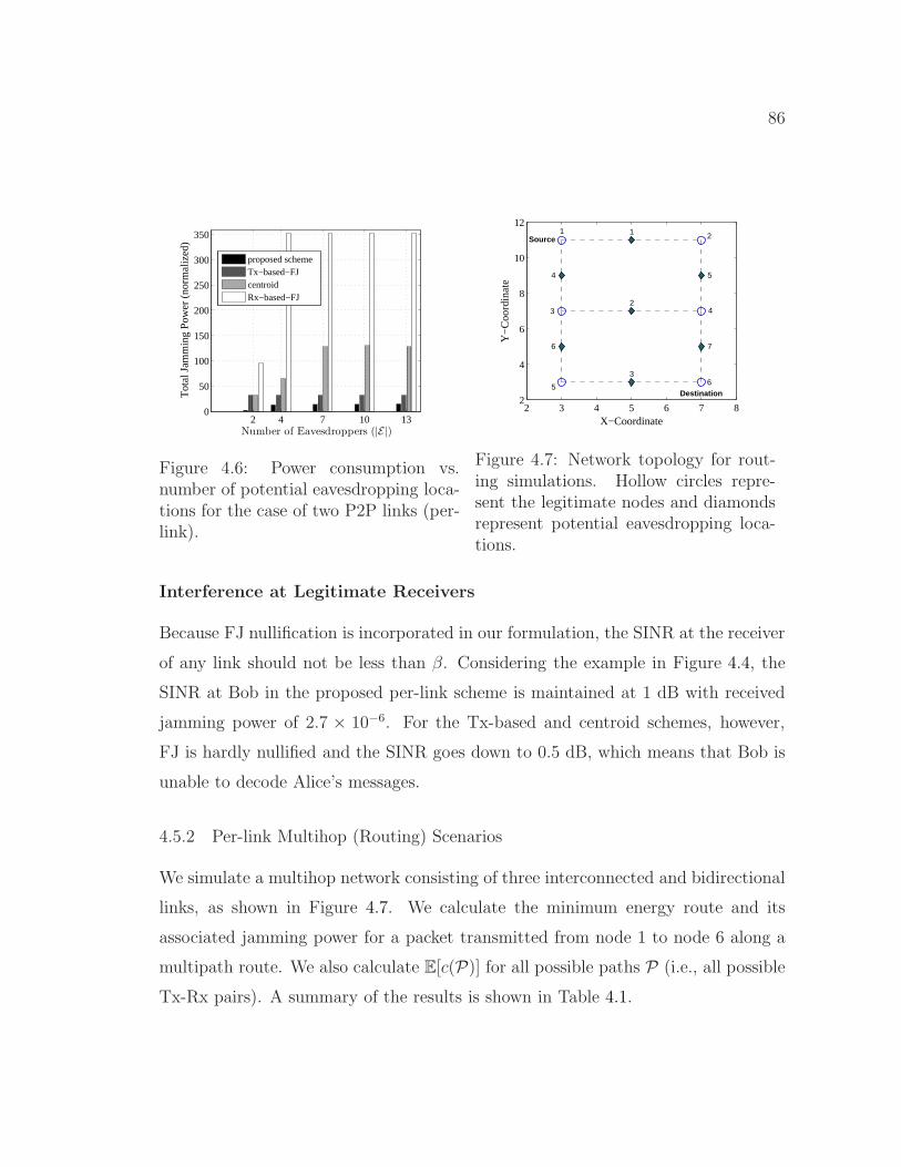
86
2 4 7 10 130
50
100
150
200
250
300
350
Number of Eavesdroppers (|E|)
Tot
al J
amm
ing
Pow
er (
norm
aliz
ed)
proposed schemeTx−based−FJcentroidRx−based−FJ
Figure 4.6: Power consumption vs.number of potential eavesdropping loca-tions for the case of two P2P links (per-link).
2 3 4 5 6 7 82
4
6
8
10
121
2
3 4
56
1
2
3
4 5
6 7
X−Coordinate
Y−
Coo
rdin
ate
Source
Destination
Figure 4.7: Network topology for rout-ing simulations. Hollow circles repre-sent the legitimate nodes and diamondsrepresent potential eavesdropping loca-tions.
Interference at Legitimate Receivers
Because FJ nullification is incorporated in our formulation, the SINR at the receiver
of any link should not be less than β. Considering the example in Figure 4.4, the
SINR at Bob in the proposed per-link scheme is maintained at 1 dB with received
jamming power of 2.7 × 10⁻⁶. For the Tx-based and centroid schemes, however,
FJ is hardly nullified and the SINR goes down to 0.5 dB, which means that Bob is
unable to decode Alice’s messages.
4.5.2 Per-link Multihop (Routing) Scenarios
We simulate a multihop network consisting of three interconnected and bidirectional
links, as shown in Figure 4.7. We calculate the minimum energy route and its
associated jamming power for a packet transmitted from node 1 to node 6 along a
multipath route. We also calculate E[c(P)] for all possible paths P (i.e., all possible
Tx-Rx pairs). A summary of the results is shown in Table 4.1.

87
Table 4.1: Comparison of the proposed per-link scheme and the fixed-placementschemes in terms of the cost of the minimum-energy path (|L| = 2).
Proposed Tx-based FJ Centroid Rx-based FJ
Best path 1-2-4-6 1-2-4-6 1-3-4-6 1-2-4-6
Cost 7 48 128 304
E[c(P)] 5.5 26.7 75.5 167.5
4.5.3 Network-wide Scenarios
To study the energy efficiency of our network-wide optimization strategy, we com-
pare our proposed per-link P2P and network-wide P2P schemes in terms of the
total jamming power required to cover the whole network when |L| = 2. As shown
in Figure 4.8, the network-wide scheme reduces power consumption by 14%–38%
relative to the per-link scheme. Note also that the network-wide scheme allows for
simultaneous operations of different links because it ensures the nullification of the
FJ signals at all legitimate receivers.
4.6 Summary
In this paper, we exploited friendly jamming for PHY-layer security in small-scale
multi-link wireless networks in the presence of eavesdroppers. We jointly optimized
the powers and locations of the friendly jamming nodes so as to minimize the to-
tal jamming power required to secure legitimate transmissions. Distributed MIMO
techniques are used to nullify the friendly jamming signals at legitimate receivers.
A signomial programming problem was formulated and approximated as a convex
geometric programming problem using condensation techniques. We then proposed
two optimization strategies: per-link and network-wide (all links jointly). It was
shown that our per-link scheme outperforms previous schemes in terms of energy
efficiency (55–99 percent power saving). Moreover, the network-wide optimization
was shown to be more energy-efficient than per-link scheme (14–38 percent addi-

88
4 7 10 130
5
10
15
20
Number of Eavesdroppers (|E|)
Tot
al J
amm
ing
Pow
er (
norm
aliz
ed)
network−level−schemelink−level−scheme
Figure 4.8: Power consumption of the network-wide and per-link schemes vs. thenumber of potential eavesdropping locations for the case of two P2P links.
tional power saving) and also requires about half the number of friendly jamming
nodes than per-link optimization. For multihop scenarios, we proposed a routing
metric that finds a secure path that requires minimal jamming power.

89
CHAPTER 5
Friendly CryptoJam
5.1 Introduction
Albeit using friendly jamming results in degrading Eve’s channel (see Chapter 4),
it does not completely immune wireless communications to eavesdropping. Eve
can perform low-level RF analysis to obtain SCI even when PHY/MAC headers are
encrypted or cannot be successfully decoded, a threat that has not been well-studied
in the literature. Consider, for example, the detection of the payload’s modulation
scheme of an entirely encrypted PHY frame. Using an off-the-shelf device such as a
signal analyzer or a dedicated device equipped with an FPGA [55], one can detect
the modulation scheme, and accordingly estimate the payload’s data rate. The same
device can also measure the frame duration and determine the packet size based on
the estimated data rate.
5.1.1 Existing Countermeasures for Hiding SCI
Before describing the limitations of various techniques that have been proposed to
prevent Eve from obtaining SCI or intercepting PHY/MAC headers, we first explain
why a naive approach based on encrypting such headers is not practical. To decrypt
such headers, the intended receiver (Bob) needs to identify the sender at PHY layer
among several potential senders and apply the right decryption key. When headers
are fully encrypted, none of their fields (e.g., sender’s MAC address) can be used
for identification. Similarly, MAC address randomization that has recently been
employed for hiding the true address in probe requests (e.g., in Apple iOS 8.1.3) is
90
also not sufficiently helpful. Besides its other vulnerabilities [56], such hidden MAC
identifier still cannot be used for decryption at the PHY layer. Likewise, Alice-Bob
channel or Alice’s radiometric features cannot be used as an identifier because of
mobility and/or inaccuracy of low-end RF receivers [57].
Techniques to prevent SCI leakage can be divided into three categories: SCI
obfuscation at upper layers, rate hiding techniques [58, 59], and eavesdropper deaf-
ening at the PHY layer. Upper-layer SCI obfuscation techniques aim at invalidat-
ing SCI, usually at the cost of traffic overhead. At the application layer, packet
padding can be used to alter the traffic statistics. However, Dyer et al. [15] demon-
strated that even if packet lengths are obfuscated, training a website-traffic classifier
based only on the total bandwidth can result in a very high classification accuracy.
They also proposed a countermeasure that obfuscates the total bandwidth, but with
100%−400% overhead. Traffic reshaping [60] is a MAC layer technique that involves
configuring several virtual interfaces with different MAC addresses for the same de-
vice and dynamically distributing the traffic among them so as to create different
traffic patterns on each MAC interface. This prevents Eve from associating all the
packets with the same sender. Similarly, the sender and receiver can agree on a
set of confidential time-rolling MAC addresses (e.g., [6,7]. However, these identifier
concealment techniques cannot hide certain attributes, including the modulation
scheme and transmission rate.
More recently, trellis structure has been employed for providing security [58,
61–63]. To hide the payload’s modulation scheme, Conceal and boost modulation
(CBM) was proposed in [58], whereby convolutional codes based on a Generalization
of Trellis Coded Modulation (GTCM) are used, combined with a cryptographic
interleaving mechanism. In order to eliminate the dependency among successive
symbols, the authors proposed securely interleaving blocks of p symbols, where p
is a prime number. Large p is required to prevent exhaustive search and known-
plaintext attacks on the interleaved blocks. GTCM directly encodes the symbols of

91
any modulation scheme into the highest-order modulation scheme. A symmetric-
key scheme was also proposed to encrypt the PHY-layer header. While CBM can
achieve up to 8 dB asymptotic coding gain (in idealized simulation scenarios), it
does not address the issue of sender identification and the decryption of the PHY-
layer header. Moreover, the complexity of GTCM codes, interleaving, and expensive
symmetric-key encryption result in a large decoding delay at Bob. CBM also suffers
significantly from inaccurate frequency offset (FO) estimation (> 4 dB loss) due to
acute susceptibility of higher-order modulation schemes to phase offset.
PHY-layer eavesdropper deafening techniques include FJ, e.g., [64–66]. In this
method, Eve’s channel is degraded without impacting the channel quality at Bob.
This is done using MIMO techniques or by having relay nodes transmit a jamming
signal that is harmless to Bob. However, three fundamental issues limit the prac-
ticality of this approach. First, if Eve is equipped with multiple antennas, she can
cancel out a transmitter-based FJ signal [67,68]. For example, Schulz et al. [68] ex-
ploited a known part of Alice’s signal (e.g., frame preamble) to estimate the precod-
ing matrix used in generating the FJ signal and then eliminate it from the received
signal at Eve. This matrix is supposed to be secret and unique, as it depends on
the channel state information (CSI) for the Alice-Bob channel, i.e., it represents a
signature of the Alice-Bob channel. This known-plaintext attack can thwart any se-
curity scheme that relies on data prefiltering (precoding) at Alice. Other techniques
such as beamforming and orthogonal blinding (e.g., [64]) are essentially based on
precoding, and so are insufficient. Furthermore, the uniqueness of the Alice-Bob
CSI has been shown not to be true in the presence of strong LOS component [69].
Specifically, a few adversaries located several (∼ 18) wavelengths away from Bob
can cooperatively reconstruct the signature for the Alice-Bob channel.
Second, FJ requires additional transmission power and antenna(s), which come
at the expense of throughput reduction for the information signal. The jamming
power may need to be even higher than the information signal power to achieve

92
0 10 20 30 40 50−3
−2
−1
0
1
2
Sample index
I−va
lue
Original information signal
Measured information + jamming
(a) I-values of a QPSK-modulated information sig-nal when combined with an FJ signal (received JSRat Eve= 0 dB).
−70 −60 −50 −40 −30 −20 −10 00
0.2
0.4
0.6
0.8
1
Jamming−to−Signal Ratio (dB)
Nor
mal
ized
Sym
bol C
ross
−C
orre
latio
n
011101
011100
(b) Cross-correlation between received (informa-tion + FJ) signal and one of two possible valuesfor the information signal vs. JSR (011100 is thecorrect value).
Figure 5.1: Cross-correlation attack on a semi-static QPSK-modulated signal thatis superposed on an FJ signal.
non-zero secrecy capacity [65]. Moreover, Alice may not have sufficient number of
antennas (degrees of freedom) to apply friendly jamming.
Third, transmitter- and receiver-based FJ (e.g., [66]) are still vulnerable to cross-
correlation attacks on (unencrypted) semi-static header fields. In these attacks, a
header field can take one of a few possible values. Eve can detect the start of a
frame, even if it is combined with a jamming signal [70]. By knowing the underlying
header format (i.e., where each field is supposed to start), Eve can locate the start

93
Figure 5.2: Combining QPSK-modulated and BPSK-modulated signals with differ-ent powers results in a 8-symbol constellation map.
time of the targeted field in the header. Figure 5.1(a) shows an example of the
received in-phase (I) values of a sequence of modulated symbols containing a semi-
static header field plus an FJ signal. Even though Eve may not be able to decode
the received signal, she can correlate the modulated symbol of each possible value
of this field with the received signal and guess the true field value. In general, this
cross-correlation attack can be formulated as a composite hypothesis testing. We
show a simple example in Figure 5.1(b), which depicts the cross-correlation between
the combined received signal and one of two possible field values (011100 is the
true value and 011101 is another possible value). The cross-correlation is shown as
a function of the jamming-to-signal ratio (JSR). Each point is the average of 100
simulation trials. The plot shows that Eve can successfully determine the true value
even when the FJ power is as high as the information signal power.
Furthermore, FJ cannot effectively hide the modulation scheme and frame du-
ration. If the jamming signal is random, Eve can employ detection techniques for
low SNR (e.g., [55, 71]) to detect the modulation scheme. Even if the FJ signal
takes the form of a digitally modulated signal (as opposed to random noise), Eve
may still detect the modulation scheme of the payload by analyzing the order and
constellation map of the received superposition. The superposition of the I and
Q components of the complex symbols that belong to the two signals results in a
modulation scheme whose order and constellation depend on the original schemes
and the respective received powers. For example, the constellation map resulting
from the superposition of two signals, one modulated with QPSK and the other
with BPSK, can disclose the constituent modulation schemes (see Figure 5.2).

94
5.1.2 Overview of Friendly CryptoJam
To address the aforementioned limitations, we propose Friendly CryptoJam (FCJ),
a form of friendly jamming but with the information and jamming signals intermixed
right after the digital modulation phase and before the frame is transmitted over
the air. Our intermixing method makes FCJ a form of modulation-level encryption
(for the whole frame) and also a form of modulation obfuscation (for the PHY-
layer payload). To generate a secret FJ sequence, Alice exploits an unpredictable
sender identifier as a seed, which is then embedded in the frame preamble (i.e., a
PHY-layer identifier). This way, Bob can identify the sender for key lookup and
synchronize with Alice in generating the same FJ sequence. Hereafter, we call this
secret sequence as “FJ traffic”. This identifier is independent of the link features and
is robust to known plaintext attacks. The proposed modulation encryption preserves
the Gray coding structure of the encrypted symbols on the original constellation
map. In contrast to conventional (digital domain) encryption, the encryption in
FCJ is modulation-aware.
Using parts of the same FJ traffic, encrypted symbols of the payload are then
coded and mapped (upgraded) to the constellation map of the highest-order (target)
modulation scheme supported by the system. Modulation upgrade is done in a way
that prevents the original modulation scheme of the payload from being disclosed,
i.e., it provides indistinguishable modulation unification. In contrast to the uncoded
modulation unification in the initial design [59] and variable-rate coding for upgrad-
ing different modulation schemes to same target modulation scheme in CBM [58],
the proposed mapping employs only two minimal trellis-coded modulation (TCM)
codes with constraint length ≤ 2 (and constant rate for the same target modulation
scheme). These codes are combined with the FJ traffic so as to obfuscate the original
payload’s modulation scheme through continuously moving the coded symbols on
the constellation map while maintaining BER performance. Compared to [58], such
mapping enjoys lower complexity, decoding delay, and susceptibility to FO estima-

95
tion errors. We further provide an analytical study of the impact of these errors.
In addition, FCJ hides the modulation scheme and the TCM code without symbol
interleaving. In contrast to classic FJ techniques, a single antenna is sufficient to
transmit both the information and FJ signals.
One important challenge in designing FCJ is how to modify the FJ traffic on a
per-frame basis. Not changing the FJ traffic during a session opens the door for a
dictionary attack against semi-static header fields. Furthermore, relying on a single
(long) secret sequence for the FJ traffic makes the design prone to synchronization
errors. To ensure consistency in the generation of FJ traffic at Alice and Bob, Alice
conveys a frame-specific seed (e.g., frame and sender ID) whose modulated value
is superposed onto the known frame preamble. Together with the session key, this
seed is fed into an appropriately selected pseudo-random number generator (PRNG)
to generate the secret FJ traffic. The seed is also used for sender identification at
PHY layer. Superimposing the seed with the preamble, however, may degrade the
preamble’s crucial functions (including frame detection). To prevent that, we exploit
the low cross-correlation property of cyclically rotated Barker sequences to construct
a seed-bearing signal in 802.11b systems.
FCJ complements conventional data encryption and upper-layer traffic manipu-
lation techniques by providing protection for the entire frame. The combination of
modulation encryption and indistinguishable modulation unification prevents any
SCI-based classification. It guards against any attack that is based on the payload’s
modulation scheme or unencrypted header fields. A high-level example of FCJ is
given in Figure 5.3.
5.2 Background – PHY-layer Attributes
(1) PHY-layer header fields. Many standards, including 802.11 variants, specify
the frame length and payload’s transmission rate in the PHY header. The trans-
mission rate is typically adjusted based on channel conditions, resulting in different

96
Figure 5.3: Example of using Friendly CryptoJam to hide the header fields andthe modulation scheme (and payload size) of two frames. Headers and payloadare modulated-encrypted and modulation-unified without changing the informationrate and frame duration. Under FCJ, a seed (ID) is overlaid on the original framepreamble (P ), leading to a new preamble (P ∗ = P + ID).
frame durations (in seconds) for the same payload. For example, in 802.11b/g, the
data rate and the modulation scheme are specified in the ‘Signal’ and ‘Service’ fields,
respectively. In 802.11a, the ‘rate’ field represents both the transmission rate and
the modulation scheme (BPSK, QPSK, 16-QAM, or 64-QAM). The ‘Modulation
and Coding Scheme’ field in 802.11n is similar to the rate field in 802.11a. All
802.11 variants specify a ‘length’ field, which represents the payload size in octets
(for 11a/n) or in milliseconds (for 11b).
(2) Detection of lower-layer fields. Typically, the preamble and the PHY
header are transmitted at the lowest supported rate.1 Transmission rate for the
frame payload (including MAC header) is adjusted adaptively. The 802.11i security
amendment provides integrity only for the MAC header. The preamble, PHY, and
MAC headers are all transmitted in the clear, allowing an adversary to intercept
them and obtain the transmission rate information for the payload. This rate may
also be determined by detecting the payload’s modulation scheme and combining
that with the frame length to compute the packet size. A modulation scheme is
usually associated with two or three data rates of different code rates. For example,
1The only exception is the short header format of 802.11b/g, which uses DQPSK.

97
in 802.11a, 16-QAM is used for data rates 24 and 36 Mbps. Hence, by determining
the modulation scheme, it is rather easy for the adversary to guess the data rate.
5.3 System Model
We consider a wireless network in which each link consists of single-antenna trans-
mitter (Alice) and receiver (Bob). The link operates in the presence of one or more
eavesdroppers (Eve). Alice and Bob first create a shared pairwise transient key
(PTK) through the EAPOL 4-way handshake of 802.11i. PTK is used to encrypt
the payloads, but as explained later we also use it to generate FJ traffic and frame
IDs at the PHY layer. Each node maintains a table of PTKs and session IDs of
all known neighbors in the network2. To customize FCJ, They exploit knowledge
of the standard preamble and frame format without introducing a new preamble
or header field (i.e., wasting the throughput). This way, customizing the design to
other systems with a known Barker-based preamble structure and an arbitrary but
known set of modulation schemes is straightforward. Without loss of generality,
we consider a rate-adaptive system that uses the preamble of 802.11b. For sim-
plicity, when presenting FCJ, we consider BPSK, QPSK, 16-QAM, and 64-QAM
modulation schemes for the payload.
Eve knows the frame structure and protocol semantics. She can be a passive
eavesdropper or a reactive jammer who selectively jams upon analyzing the early
part of a frame. Eve’s attacks may include cross-correlation attacks (e.g., Fig-
ure1(b)), rate-adaptation attack [19], device-based user-tracking attacks, dictionary
attacks, known-plaintext attack [68], key-recovery attack, and any data-rate-based
traffic classification attack. We allow Eve to be equipped with multiple antennas.
She can also perform RF analysis, correlation, and (statistical) modulation detec-
2Because the (encrypted) MAC address is decoded after the PHY header, it cannot be usedto retrieve the corresponding PTK at the PHY layer. Session ID is used instead to distinguishbetween different neighbors.

98
Figure 5.4: Transmission chain at Alice under FCJ. Insertion points (1), (2), and(3) refer to modulation encryption, TCM-based modulation unification, and messageembedding within the preamble.
tion. Alice may employ any traffic classification mitigation technique (e.g., traffic
morphing or random padding) at upper layers, but does not pad a packet to a
fixed size (e.g., ‘Maximum Transmission Unit’). Otherwise, if the PHY layer re-
ceives packets of the same size, the frame duration will reveal the actual modulation
order.
Figure 5.4 shows a schematic view of Alice’s transmit chain and the insertion
points of FCJ’s components, which include modulation encryption (point 1), mod-
ulation unification (point 2) and frame/session ID embedding (point 3). Starting
with the MAC header, once the frame payload arrives at Alice’s PHY layer, Alice
computes the PHY-header fields, including the modulation scheme for the payload
that is calculated based on same rate-adaptation algorithm. The preamble, PHY
header, and payload are then scrambled and modulated. They are then passed to
the pulse shaping filters and transmitted over the air. Bob, on the other hand, de-
tects the preamble and extracts the frame ID embedded in it to regenerate the FJ
traffic and estimates the CSI. Subsequently, Bob recovers and decrypts the header
to extract the payload’s modulation scheme, which is used to recover the rest of the
frame.
5.4 Modulation Unification
In this section, we introduce a method for indistinguishably unifying different modu-
lation schemes using FJ traffic. For now, we assume that the FJ sequence is already
99
available at both Alice and Bob. Furthermore, we assume that Bob can decrypt
the headers and obtain the true modulation scheme. Confidential generation and
synchronization of the FJ sequence will be explained in Section 5.5 along with the
modulation encryption scheme.
5.4.1 Uncoded Modulation Unification
To prevent any rate-based SCI classification, the modulation scheme used for dif-
ferent frame payloads should always look the same to Eve. We achieve that by
embedding the payload’s original modulation symbols in the constellation map of
the highest-order modulation scheme supported by the underlying system (denoted
by MM). However, when upgrading the modulation scheme, we want to preserve
the same demodulation performance at Bob.
To unify various payload modulation schemes, denoted byMi, i = 1, 2, . . . ,M ,
each modulated symbol of Alice’s payload is combined with one modulated FJ traffic,
producing one point in the target constellation map. The distribution of these points
in the target constellation map must be uniform, similar to the distribution of the
points of a MM -modulated signal. As long as the generated symbols are equally
probable and a given symbol is independent of the previous and next symbols (from
Eve’s perspective), Eve cannot determine ifMi has been obfuscated.
In general, a higher-order modulation scheme is more susceptible to demodu-
lation errors. To illustrate, let the FJ traffic sequence be j and let Fj(Mi) be a
mapping, known to both Alice and Bob, that is used to embed the symbols ofMi,
(whereM1 andMM are the lowest- and highest-order modulation schemes, respec-
tively) into the constellation map ofMM . The minimum Euclidean distance between
the symbols in the constellation ofMi, denoted by dmin,i, specifies the probability
of a demodulation error at a given SNR value. This dmin,i generally decreases with
i. Tables 5.1 and 5.2 depicts dmin,i for the 802.11a system after taking into account
a modulation-dependent normalization factor KMOD [1]. KMOD is a coefficient that

100
is multiplied by the (I,Q) values to achieve the same average symbol-power across
different modulation schemes. To maintain the same dmin,i after upgrading Mi to
MM , i.e., achieve the same BER, any two neighboring points in the constellation of
Mi should be mapped to two points inMM whose distance is no smaller than their
distance inMi. At the same time, all the resulting constellation points ofMM as
observed by Eve must be equally probable (as when a random information sequence
is modulated using MM). Otherwise, Eve may guess Mi by performing statisti-
cal analysis. In the following, we explain an uncoded mapping Fj, first proposed
in [59], which fulfils both of the above design requirements. Note that modulation
unification is not applied when i = M .
For a given Mi, our scheme defines |MM ||Mi| equal-size and nonoverlapping sets of
constellation points inMM , where |Mi| is the number of constellation points inMi.
The constellation points ofMi can be mapped to any of these sets, but the selection
of a set depends on j and hence can be different from one symbol to another. For
any symbol s that is modulated usingMi, Alice needs (log2 |MM | − log2 |Mi|) FJbits to select one of the |MM |/|Mi| sets. The value of s determines one of the
points inside the selected set. So Alice picks the first log2|MM ||Mi| bits in j for the first
symbol to be transmitted, the next log2|MM ||Mi| bits for the second symbol, and so on.
The same bits in j always point to the same target set, i.e., Fj(Mi) is static. This
ensures that the transmitted symbols are equally probable, considering that the bits
in j are randomly distributed (so as Alice’s symbols). As explained in Section 5.5,
we rely on a cryptographic hash function like SHA-3 to generate j.
Let j, j = 0, . . . , |MM |/|Mi| − 1, be the decimal representation of the bits in j
that are associated with s, and let Uj = {u0j , . . . , u
|Mi|−1j } be the corresponding target
set on the constellation map ofMM . During the decoding process, Bob knows j and
Mi. To obtain the original symbol s, Bob first removes all the constellation points
of MM except those belonging to Uj. He then follows a standard demodulation
process to determine the most likely symbol in Uj, given the observed symbol.

101
i Mi KMOD[1] dmin,i dmin
(Fj(Mi)
)γi(3) γ
(2)i (3) γ
(4)i (3)
1 BPSK 1 2 4/√5
4/5 ≃−0.969 dB
0.9 ≃−0.46 dB
6.8/4 ≃2.3 dB
2 QPSK 1/√2 2/
√2 4/
√10
4/5 =−0.969 dB
1 = 0 dB1.6 ≃
2.04 dB
316-
QAM1/√10 2/
√10 2/
√10 1 = 0 dB N/A N/A
Table 5.1: Parameters of the optimal mapping from BPSK and QPSK to 16-QAM.
i Mi KMOD[1] dmin,i dmin
(Fj(Mi)
)γi(4) γ
(2)i (4) γ
(4)i (4)
1 BPSK 1 2 8/√21
16/21 =−1.181 dB
66/84 ≃−1.05 dB
130/84 ≃1.9 dB
2 QPSK 1/√2 2/
√2 8/
√42
16/21 =−1.181 dB
68/84 ≃−0.92 dB
128/84 ≃1.83 dB
316-
QAM1/√10 2/
√10 4/
√42
2/2.1 ≃−0.21 dB
5/4.2 ≃0.76 dB
4/2.1 ≃2.8 dB
464-
QAM1/√42 2/
√42 2/
√42 1 = 0 dB N/A N/A
Table 5.2: Parameters of the optimal mapping from 802.11a modulation schemes to64-QAM.
Next, we discuss an optimal strategy for constructing the sets Uj by clustering
the |MM | symbols in the constellation map of MM into |Mi| equal-size disjoint
partitions. In here, optimality is taken w.r.t. maximizing the minimum distance
between all pairs that belong to the same set. Let dmin
(Fj(Mi)
)be the minimum
distance between any two elements in Uj over all possible j, j = 0, . . . , |MM |/|Mi|−1.For an arbitrary modulation scheme MM , the problem of optimizing Uj to maxi-
mize dmin
(Fj(Mi)
)(a max-min problem) can be easily mapped (converted) via
a sign change to the min-max clustering problem [72], which can be solved in
O(|MM |2 |Mi| log(|MM |)) time. For the special cases of MM = 8-PSK and 16-
QAM, an optimal solution to this problem was obtained in [73] by applying the
“mapping by set partitioning” rule, which successively partitions the sets into sub-
sets with increasing minimum distances.
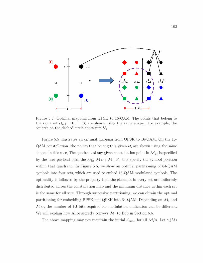
102
Figure 5.5: Optimal mapping from QPSK to 16-QAM. The points that belong tothe same set Uj, j = 0, . . . , 3, are shown using the same shape. For example, thesquares on the dashed circle constitute U0.
Figure 5.5 illustrates an optimal mapping from QPSK to 16-QAM. On the 16-
QAM constellation, the points that belong to a given Uj are shown using the same
shape. In this case, The quadrant of any given constellation point inMM is specified
by the user payload bits; the log2 |MM |/|Mi| FJ bits specify the symbol position
within that quadrant. In Figure 5.6, we show an optimal partitioning of 64-QAM
symbols into four sets, which are used to embed 16-QAM-modulated symbols. The
optimality is followed by the property that the elements in every set are uniformly
distributed across the constellation map and the minimum distance within each set
is the same for all sets. Through successive partitioning, we can obtain the optimal
partitioning for embedding BPSK and QPSK into 64-QAM. Depending onMi and
MM , the number of FJ bits required for modulation unification can be different.
We will explain how Alice secretly conveysMi to Bob in Section 5.5.
The above mapping may not maintain the initial dmin,i for allMi’s. Let γi(M)

103
Figure 5.6: Optimal mapping from 16-QAM to 64-QAM. The points that belong tothe same set Uj, j = 0, . . . , 3, are shown using the same shape.
be the demodulation performance gain of mappingMi intoMM :
γi(M) =d2min
(Fj(Mi)
)
d2min,i
, i = 1, . . . ,M − 1. (5.1)
For optimal mapping to 16-QAM and 64-QAM, BPSK (QPSK) will have a gain of
−1.181 dB (1.181 dB loss) and −0.969 dB (0.969 dB loss), respectively, as shown
in Tables 5.1 and 5.2. We compensate for this loss by applying a novel untraceable
modulation coding technique.
5.4.2 Residual FO Estimation Error
Besides the SNR and dmin,i, the demodulation performance at Bob depends on how
accurate he estimates ∆f . Residual error in estimating ∆f manifests itself as a
time-varying phase error that increases linearly with the symbol index and may
eventually displace a received symbol out of its expected region in the constellation
map (see Chapter 2). Depending on the frame duration, the residual FO may move a
received symbol to a wrong point on the constellation map, causing a demodulation
error. Such error . Therefore, for the same residual FO and SNR level, longer frames
experience more symbol/bit error rate towards the end of the frame.

104
Figure 5.7: Example of uneven impact of phase offset on symbols with differentamplitudes when QPSK symbols are mapped to four 64-QAM symbols.
The higher density of the symbols in higher-order modulation schemes con-
tributes to higher susceptibility of these schemes to FO estimation errors. Although
applying Gray coding in these schemes alleviates the consequences of symbols dis-
placement on BER, higher-order modulation schemes experience demodulation er-
rors by smaller phase offsets. Therefore, any unification scheme that maps the
Mi-modulated symbols to a denser set of symbols in MM incurs a performance
loss, especially if the symbols are correlated via coding and a demodulation error
may propagate to the subsequent symbols (e.g., in [58, 73]). One advantage of the
uncoded modulation unification in FCJ over [58] is that the target sets Uj have the
same density asMi, i.e., |Uj | = |Mi|.However, the symbols in a target set Uj , which is used to embed in MM the
symbols of symmetric constellation map of Mi, are asymmetrically distributed.
Therefore, with the same phase offset ϕ, different symbols experience uneven dis-

105
0 0.5 1 1.5 2 2.5 3Phase Offset ϕ (rad)
0
0.2
0.4
0.6
0.8
1
Ave
rage
BE
R
BPSK (Default)MM = 16-QAMMM = 64-QAM
(a)Mi = BPSK.
0 0.5 1 1.5 2 2.5 3Phase Offset ϕ (rad)
0
0.2
0.4
0.6
0.8
1
Ave
rage
BE
R
QPSK (Default)
MM = 16-QAM
MM = 64-QAM
(b)Mi = QPSK.
0 0.5 1 1.5 2 2.5 3Phase Offset ϕ (rad)
0
0.1
0.2
0.3
0.4
0.5
0.6
0.7
Ave
rage
BE
R
16-QAM (Default)
MM = 64-QAM
64-QAM (Default)
(c)Mi = 16-QAM or 64-QAM.
Figure 5.8: Impact of phase offset on differentMi andMM combinations in mod-ulation unification.
placements. That means some of the symbols are more robust to phase offset and
other symbols are more vulnerable. We illustrate this in Figure 5.7 with an exam-
ple of one of the Ujs when hiding QPSK in 64-QAM. The coordinates shown with
dashed lines are the ones used for demodulating the four 64-QAM-modulated sym-
bols at Bob. These lines are the boundaries for the optimal demodulation regions
in AWGN channel. However, unequal amplitudes of the symbols results in different
displacement lengths for the same phase offset ϕ. The dashed arcs represent the
amount of displacement that can move a symbol to its neighboring region. The
symbol with the smallest amplitude never leaves its expected region, while the sym-
bol with the highest amplitude may easily leave its region when the FO estimation
is not accurate.

106
In Figure 5.8, We compare the average BER of differentMis embedded inMM =
16-QAM and 64-QAM to the BER of original Mis for different ϕ values. When
Mi = BPSK or QPSK (Figure 5.8(a) and Figure 5.8(b)), applying modulation
unification makes the demodulation more vulnerable to small ϕ values. For example,
as long as ϕ < π/4, QPSK-modulated symbols will not experience any bit error.
However, when these symbols are mapped to 16-QAM or 64-QAM symbols, the
error-free phase offset range is shrunk to ϕ < π/6. That means more symbols in
a frame will be demodulated in error. On the other hand, depending on the phase
offset value, modulation unification can make the demodulation more robust to
residual errors (e.g., when π/4 ≤ ϕ < π/2).
When Mi = 16-QAM, modulation unification has little impact on the average
BER, as can be seen in Figure 5.8(c). In this figure we also plot the BER for
64-QAM. Comparing this plot versus the ones of BPSK and QPSK, we observe high
susceptibility of any unification scheme that directly maps low-order modulation
schemes to 16-QAM and 64-QAM (e.g., CBM [58]).
5.4.3 Untraceable Trellis-Coded Modulation Unification
Assuming accurate FO estimation, FCJ can maintain the same demodulation per-
formance of the original modulation scheme by coding theMM -modulated symbols.
Coding creates dependency among successive symbols, which can be exploited at
Bob to guess the possible symbols sequences; hence, reducing the demodulation
error. To construct these possible sequences at Bob, trellis diagram is employed,
based on which the most probable path (i.e., sequence) is identified. Trellis-coded
modulation [73, 74] is a generic technique to encode the modulated symbols of a
given modulation scheme by introducing dependency among modulation symbols
of a higher-order modulation scheme and transmitting them. A set of “states”
is defined to impose the dependency where the state transitions (and hence the
transmitted symbols) are specified by information bits. This combines coding and

107
modulation operations instead of performing them separately [73, 74]. Figure 5.9
shows an example of a 2-state TCM source and its corresponding trellis diagram
that encodes BPSK symbols using a 4-symbol modulation scheme, which is a way of
upgrading BPSK to QPSK. Introducing the dependency in FCJ is possible because
a given symbol s may correspond to multiple symbols ofMM (for different j values).
For the time being, however, let the choice of set Uj be based on only the current
source state. The asymptotic coding gain of TCM is defined as
γ(n)i (M) =
d2freed2min,i
(5.2)
where dfree is the minimum total Euclidean distance between the symbols along
any two distinct paths in the trellis diagram (free distance) and n is the number of
states. To get the benefit of TCM, dfree should be at least as large as dmin,i. While,
in general, complex TCM codes of rate log2 |Mi|/ log2 |MM | can be designed to
significantly improve the gain [58], in here we exploit two simple yet efficient codes
of rate log2 |Mi|/ (log2 |Mi|+ 1) which facilitate our indistinguishable modulation
unification. These codes are based on either two-state (Figure 5.9) or four-state
(Figure 5.10) TCMs presented in [73] with constraint lengths of 1 and 2, respectively.
They embed |Mi| symbols into 2|Mi| symbols of MM . (When Mi 6= BPSK, the
same structures are used but multiple parallel edges need to be defined for each
state transition.) The 2|Mi| symbols consist of the symbols of two sets Uj1 and Uj2 ,j1, j2 ∈ 0, . . . , |MM |/|Mi| − 1. (In Figure 5.9 and 5.10, U0 and U1 are used.)
Using Ungerboeck’s symbol assignment rules (as shown in Figure 5.9 and Fig-
ure 5.10), we maximize dfree for each TCM scheme and eliminate the performance
loss of the uncoded modulation unification, without incurring significant decoding
complexity. (Note that, for example, the least-complex code in [58] for mapping
from BPSK to 64-QAM has the constraint length of 5.) The coding gains of the
proposed TCM schemes are shown in Tables 5.1 and 5.2. The two-state TCM main-
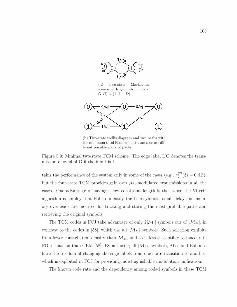
108
(a) Two-state Markoviansource with generator matrixG(D) = (1 1 +D).
(b) Two-state trellis diagram and two paths withthe minimum total Euclidean distances across dif-ferent possible pairs of paths.
Figure 5.9: Minimal two-state TCM scheme. The edge label I/O denotes the trans-mission of symbol O if the input is I.
tains the performance of the system only in some of the cases (e.g., γ(2)2 (3) = 0 dB),
but the four-state TCM provides gain over Mi-modulated transmissions in all the
cases. One advantage of having a low constraint length is that when the Viterbi
algorithm is employed at Bob to identify the true symbols, small delay and mem-
ory overheads are incurred for tracking and storing the most probable paths and
retrieving the original symbols.
The TCM codes in FCJ take advantage of only 2|Mi| symbols out of |MM |, incontrast to the codes in [58], which use all |MM | symbols. Such selection exhibits
from lower constellation density thanMM , and so is less susceptible to inaccurate
FO estimation than CBM [58]. By not using all |MM | symbols, Alice and Bob also
have the freedom of changing the edge labels from one state transition to another,
which is exploited in FCJ for providing indistinguishable modulation unification.
The known code rate and the dependency among coded symbols in these TCM
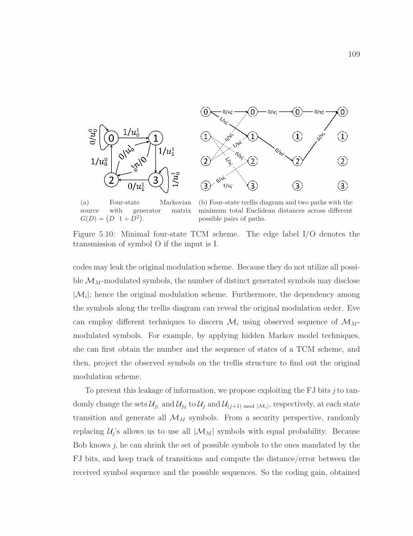
109
(a) Four-state Markoviansource with generator matrixG(D) =
(D 1 +D2
).
(b) Four-state trellis diagram and two paths with theminimum total Euclidean distances across differentpossible pairs of paths.
Figure 5.10: Minimal four-state TCM scheme. The edge label I/O denotes thetransmission of symbol O if the input is I.
codes may leak the original modulation scheme. Because they do not utilize all possi-
bleMM -modulated symbols, the number of distinct generated symbols may disclose
|Mi|; hence the original modulation scheme. Furthermore, the dependency among
the symbols along the trellis diagram can reveal the original modulation order. Eve
can employ different techniques to discern Mi using observed sequence of MM -
modulated symbols. For example, by applying hidden Markov model techniques,
she can first obtain the number and the sequence of states of a TCM scheme, and
then, project the observed symbols on the trellis structure to find out the original
modulation scheme.
To prevent this leakage of information, we propose exploiting the FJ bits j to ran-
domly change the sets Uj1 and Uj2 to Uj and U(j+1) mod |Mi|, respectively, at each state
transition and generate all MM symbols. From a security perspective, randomly
replacing Uj’s allows us to use all |MM | symbols with equal probability. Because
Bob knows j, he can shrink the set of possible symbols to the ones mandated by the
FJ bits, and keep track of transitions and compute the distance/error between the
received symbol sequence and the possible sequences. So the coding gain, obtained

110
above, remains valid. From Eve’s perspective, however, any two successive symbols
are completely independent of each other, i.e., the dependency among symbols is
destroyed, because for a given symbol, the next symbol is selected completely ran-
domly based on the random information bits together with the random FJ bits.
Therefore, the TCM codes become untraceable andMi is not disclosed to Eve.
The untraceable-TCM-based modulation unification scheme proposed above
hides the true modulation scheme of the frame’s payloads, if this payload contains
random bits. This scheme also makes it hard for Eve to guess the unencrypted parts
of the MAC (and PHY-, if unified) layer headers. For example, whenMi = BPSK
and four-state TCM is used, any of the |MM | symbols can be used according to j
to modulate an input bit, depending on the current state (see Figure 5.10(b)). As
long as the current TCM state is unknown to Eve, she cannot guess this input bit.
However, because the static mapping Fj(.) and the labeling used in the underlying
TCM structure are not necessarily secret, a transmission is still vulnerable to the
following attacks. First, if the initial state is not secret and ifMi is known (e.g., the
modulation scheme of the PHY header), Eve will be able to track the time-evolution
of the states and eventually, guess the input bits. To illustrate, the mapping Fj(.)
partitions the |MM | symbols into |MM |/|Mi| disjoint sets, one for each original
symbol s and different FJ bits j. From the inverse function Fj−1 and the current
state, Eve can determine the symbols s from their MM -modulated counterparts,
revealing the true content of that field. This is especially the case if Eve exhibits
a high SNR and can reliably detect the MM -modulated symbol. Note that TCM
does not impact Fj(.).
Another attack occurs on a semi-static field if Mi is known. In this case, Eve
can guess the field value by trying different possible TCM states in the beginning
of the field and comparing the sequence of received symbols with the few possible
symbol sequences for each initial state. In these two cases, Eve is able to extract
unencrypted fields in the PHY and (if the rate field is disclosed) MAC headers by
111
detecting the frame preamble and obtaining the MM -modulated symbols of the
target header field.
A third attack involves an unknown Mi but some parts of the payload, e.g.,
MAC header, can take one of a few possible values (or even if these semi-static
parts are encrypted but with a time-invariant cipher). Eve may again apply Fj−1 of
different Mi’s on the MM -modulated symbols and check which one produces one
of the known values. This reveals not only the content (if unencrypted), but also
the true modulation scheme of the payload.
To remedy the above vulnerabilities, we also need to encrypt PHY/MAC headers
using a time-varying cipher, e.g., a one-time pad. Such encryption, however, is not
trivial. It creates challenges and prevents some of the essential functions of the
header. For example, the decryption operation at Bob requires knowledge of the
shared key dedicated to the Alice-Bob session. This key is different for a different
session (e.g., Charlie-Bob session). In order to retrieve the right key, Bob needs to
know the sender’s identity of the incoming frame, which is typically done using the
MAC address. But with the MAC address being encrypted, Bob cannot identify
Alice and retrieve the right key. An unencrypted MAC address also cannot be
used to sender identification at the lower layer. Moreover, generating one-time pads
requires a good pseudo-random number generator that is robust to plaintext (e.g.,
semi-static fields) attacks and also time-varying seeds that are common between
Alice and Bob. In the following section, we propose a novel approach for providing
time-varying identification based on embedding a message in the preamble (i.e.,
before the to-be encrypted headers). This approach provides synchrony between
Alice and Bob for using the same seed. Note that a sender identifier based on the
Alice-Bob channel characteristics will not work when nodes are mobile. It can also
be spoofed if the channel is estimated by the attacker [69].

112
5.5 Preamble-based PHY-Layer Identifier
Alice and Bob need to establish an identification method that is robust to mobil-
ity/channel variations and can be used as a means to synchronously generate the
FJ traffic at PHY-layer. Such an identifier should also be different from one frame
to another; otherwise, a semi-static header field that can take a few possible values
(e.g., the 8-bit Signal field in 802.11b takes four possible values) would produce a
fixed set of constellation points inMM . After eavesdropping on several frame trans-
missions that may have different values for that field, Eve may estimate the part
of j used to protect that field. This can facilitate a dictionary attack and disclose
the field values. Moreover, in the case of a packet loss and retransmission, applying
the same j results in the same sequence ofMM -modulated symbols. Eve may then
correlate successive transmissions, detect retransmissions, and then exclude them
from the statistics used to fingerprint the session (e.g., packet size histogram). Fur-
thermore, if Alice and Bob instead synchronously use different parts of a common
j for different frames, the loss of an ACK would make Alice and Bob out-of-sync.
For these reasons, we require j to be generated via an identifier that varies from
one frame to another. In this section, we explain how a secret frame-specific j is
generated based on the PTK and frame/sender identifier.
We exploit a PRNG that is constructed based on a cryptographic hash func-
tion from the standardized family of SHA-3 algorithms (e.g., [75, 76]) to generate
j based on a seed value and frame IDs. These algorithms enjoy several attractive
properties. First, a single-bit change in the seed results in a completely different
hash value (equivalently, j generated by the PRNG). Therefore, as long as the seed
is not repeated, j will not be repeated (similar to an ideal one-time pad), thus pre-
venting dictionary attacks. The randomness of the seed values in our method will
be discussed in the next section. Second, if Eve captures the hash value, she cannot
use it to recover the key or the seed value used to generate j, i.e., it is one-way hash

113
and robust against chosen-plaintext attacks [76], which are stronger than known-
plaintext attacks. Third, if Eve captures some part of j (or the frame ID, defined
later), she cannot predict subsequent values of j or ID (i.e., robustness to generic
state recovery attacks) [75, 76]. Fourth, the fact that such PRNG can be built in
a very compact core and can be implemented using bitwise Boolean instructions
and rotations within bytes only [75] makes it very resource-efficient and suitable
for embedded devices with low overhead/delay requirements. Fifth, the security of
j generated by such PRNG can be compared to the security of an ideal random
number sequence that does not have any generic flaw, i.e., indifferentiability prop-
erty [75]. Altogether, the sequence j that is used for encrypting headers containing
semi-static fields and for unifying the modulation schemes provide confidentiality
for the headers and unpredictability for the modulation unification approach.
If the seed contains nothing but the secret PTK, the stream cipher j will always
remain the same. To vary j from one frame to another, we concatenate a non-secret
frame-specific ID, denoted by ID, to the PTK and compose a partially secret seed for
the given frame (similar to the method in [76]). ID is also used to simultaneously
identify and authenticate the sender/session, allowing Bob to distinguish Alice’s
transmission from other transmissions (e.g., Charlie’s) destined to Bob. FCJ embeds
ID in the frame preamble and transmits it in the clear.
With frame-specific and time-rolling IDs during a session, Eve will not be able
to identify and track the user or correlate different frames that belong to the same
session. However, Bob must be able to associate different IDs to the same sender
(e.g., Alice). We adopt an ID generation method similar to [77] and create a chain
of confidential IDs using SHA-3 hash algorithm and PTK. For the first frame, Alice
and Bob agree on an initial ID (e.g., during the 4-way handshake). The ID for
subsequent frames will be the hash of the previous frame using PTK. To account for
possible frame losses and retransmissions, Bob maintains a short chain of subsequent
IDs for each active neighbor and checks whether or not the received ID exists in

114
the chain. It is followed by the properties of SHA-3 that the chance of collision
between the IDs of different senders will be low. Moreover, by observing one ID,Eve cannot predict the next one.
5.5.1 Embedding the ID
To embed the non-secret ID, one may introduce a new field between the preamble
and the standard PHY header. However, to keep the standard PHY frame format
intact for interpretability purposes and also to avoid increasing the frame size, we
embed encoded ID onto the known preamble via analog-signal superposition. (Note
that we cannot use any reserved bits in the header(s) because the entire header is
supposed to be encrypted.) The design below is specific to the 802.11b preamble,
but the idea can be extended to other preamble structures.
Extracting ID from the superposition is critical for Bob. At the same time,
Bob does not want to lose the important functions of the preamble as a result
of this superposition. To satisfy both requirements, we propose using cyclically
rotated Barker sequences (Section 5.2) to encode Alice’s ID. When a Barker se-
quence is aligned with the original preamble, the function R(b, n) (defined in (2.8))
spikes, indicating the start of a frame. To preserve this spike, we utilize cyclically
shifted versions of the reference 11-chip Barker sequence. Every k-shifted sequence,
k = 1, . . . , 10, can be a message (ID). Because of the orthogonality of Barker se-
quences, this overlaid ID is easily detectable with RF correlation. Moreover, unless
the power of the superposition is normalized, the frame detection process will be
negligibly affected because the encoded message will have little contribution to the
correlation with the reference sequence, when aligned properly. To maintain the
original preamble power, Alice can multiply the preamble by the normalization co-
efficient of√
11/20 (i.e., 2.6 dB reduction in the power of original preamble). The
peak-to-average-power ratio (PAPR) of the preamble is also increased by 3.42 dB.
Figure 5.11(a) is an example drawn from our experiments (Section 5.6) that

115
50 100 150 200 250 300 3500
0.01
0.02
0.03
0.04
0.05
0.06
Cor
rela
tion
Val
ue
Sample index
Side spikes
Start of the frame
(a) Frame detection when the ID is embeddedin the preamble.
30 40 50 60 70 800
0.01
0.02
0.03
0.04
0.05
0.06
Cor
rela
tion
Val
ue
Sample index
Embedded message spikes
(b) Small but detectable spikes during thepreamble due to the embedded ID.
Figure 5.11: R(., n) computed over a frame.
shows the value of R(., n) when applied over a frame with two embedded rotated
Barker sequences, repeated in each half of the preamble. The preamble in this
example consists of four Barker sequences, which create a few side spikes when
the correlator is moved a multiples of 11 indices away from the beginning of the
preamble. Figure 5.11(b) zooms into the preamble and shows the two messages
spikes (i.e., spikes corresponding to the cyclicly rotated Barker sequences) between
every two successive preamble (side) spikes.
For each frame (including retransmissions), Alice generates a new ID, whichis conveyed by concatenating several k-shifted versions of the Barker sequence and
is superimposed on the original preamble in the analog domain. Specifically, let

116
Preamble (P): 0 0 +1 −1 +1 +1 −1 +1 +1 +1 −1 −1 −1 +1 −1 +1 +1 −1 +1 +1 +1 −1 −1 −1ID: 3 7 +1 −1 +1 +1 +1 −1 −1 −1 +1 −1 +1 +1 −1 −1 −1 +1 −1 +1 +1 −1 +1 +1
P∗ = P + ID +2 −2 +2 +2 0 0 0 0 0 −2 0 +2 −2 0 0 0 0 +2 +2 −2 0 0
R(P , 0) 222
Table 5.3: Example of the concatenation of two Barker sequences to embed IDvalue (3 7) in the preamble.
(k1k2 . . . kl)10 be the decimal representation of the value of ID, where ki, i = 1, . . . , l,
is the i-th most-significant digit. Then, the value of ki is conveyed in a cyclically
shifted Barker sequence with ki + 1 shift. Concatenation of the l shifted Barker
sequences produces ID (see the example in Table 5.3). Bob is still able to detect
the preamble and the ID, as shown in Figure 5.11. The steps taken by Bob to
extract ID and perform the preamble functions are summarized as follows:
1. Detect frame, estimate FO, and compensate for it.
2. Extract frame ID.
3. Construct a new reference preamble using the original preamble and the em-
bedded ID.
4. Perform channel estimation using the new preamble.
5. Look up the PTK associated with the session ID and start generating j.
5.5.2 Implication on PHY-layer Functions and Practical Issues
Embedding ID in the preamble may affect some of the preamble’s common func-
tions. We discuss how our message embedding mechanism can maintain these func-
tions.
(1) Frame detection. A typical receiver performs sliding-window correlations
using different time offsets (parameter n in (2.8)). In the case of FCJ, the ratio
between the height of the side spikes and the main spike remains the same, but the
117
superposed ID will cause a few spikes when Bob correlates the reference preamble
with the received signal at time offsets k1, . . . , kl, from the start of the preamble. To
avoid creating an alias of the actual start of the preamble, Alice makes sure that she
uses different rotation values over successive preamble bits. Let the number of such
successive rotations be l < 11 (l 6= 6). Excluding the noise and multipath channel
effect, the message spikes cannot be larger than (6−l)2
(5l)2of the highest spike, because
in every sequence of l rotations, at most one of them will perfectly align with the
correlating sequence, i.e., the original preamble. Note that the correlation value of
two Barker sequences with the same (different) rotation value(s) is |11|2 (| − 1|2).(2) FO estimation. As explained in Section 5.2, FO estimation requires two
identical repetitions of an arbitrary sequence. We satisfy this requirement by repeat-
ing the ID-bearing signal at least twice. Specifically, if Bob uses K repetitions of
the Barker sequence (preamble bits) for FO estimation, Alice places the ID-bearingsignal in the first K/2 sequences and then repeats it over the other K/2 sequences.
(If K > 2l, Alice uses the last l bits in each half to superimpose the ID.) If Alice
does not know K a priori, she only exploits the portion of the preamble that will
likely be detected by Bob. Bob can then find the start of the ID signal either by an
energy-increase detection, or by iteratively running (on each preamble bit) a series
of threshold-based correlations with nonzero rotations of the Barker sequence. Once
a correlation value exceeds the threshold, this indicates the start of the ID signal.
(3) Message capacity and error correction. There are 10 distinct rotations
of an 11-chip Barker sequence (one preamble bit). In DBPSK, this translates to 10
different IDs per preamble bit. So in every nine out of 128 bits of the preamble, 10!
different IDs of the decimal form (k1k2 . . . k9)10 can be embedded. Using DQPSK,
we can double the number of possible IDs. Given this large number, FCJ can ensure
the randomness required by the PRNG even when Alice introduces a coding scheme
over the set of IDs to reduce the ID detection errors (e.g., using IDs with large
Hamming distances).
118
(4) Channel estimation. A known sequence, such as the preamble, is often
used for channel estimation. Upon capturing ID, Bob constructs a new “temporary”
preamble by superposing the same ID-bearing signal over the original preamble, and
uses the new preamble for channel estimation.
5.5.3 Encryption of Header Fields
We apply a modulation-level stream encryption Ej(Mi) to theMi-modulated sym-
bols of the frame (payload + header)3 to randomize the location of the original
symbols in the constellation map of Mi (or equivalently, dynamically change the
mapping between a symbol s and one of the disjoint sets determined by Fj(.)). This
way, sole knowledge of Fj is not sufficient to disclose the symbol s that corresponds
to an observed MM -modulated symbol. Ej(.) can be applied before Fj or jointly
with Fj. Note that if we alternatively upgrade the modulation scheme first and then
apply encryption, Bob may not reliably decode anMM -modulated symbol.
The encryption function Ej(Mi) is performed by bit-wise XORing of the informa-
tion and FJ bits. Consider log2 |Mi| information bits, corresponding to one symbol
of the modulation schemeMi. We select log2 |Mi| successive bits from j and XOR
them with the information bits. In the symbols domain, a lookup table can be used
to map the decimal value of the FJ bits, denoted by x, and the index of information
symbols on the constellation map to the symbol index corresponding to the XOR of
the underlying information and FJ bits. According to Gray coding, adjacent points
in the constellation map ofMi have a 1-bit difference. Equivalently, the encryption
can be merged with TCM by changing edge labels ukj with u
k⊕
x mod |Mi|j per each
transition. One advantage of using an XOR operation is that adjacent constellation
points before the symbols relocation by Ej(Mi) remain adjacent after the relocation
because they are bit-wise XORed with the same FJ bits and thus the Gray coding
3We do not encrypt the preamble, since otherwise Bob cannot detect the start of the framewithout knowing in advance the sender’s identity.

119
property is preserved (in contrast to the encryption scheme in [59]). Therefore, the
BER due to demodulation errors is not impacted by modulation encryption. As
long as the FJ traffic is robust against various attacks (e.g., plaintext attack), the
encryption Ej(Mi) is secure. As we discussed earlier, SHA-3 family of hash functions
can provide us with such PRNG.
Altogether, Alice applies the composite mapping Fj
(Ej(Mi)
)to the payload
symbols. For each Mi-modulated symbol, Alice (Bob) sequentially picks a block
of log2 |Mi| + log2|MM ||Mi| bits from j to first encrypt (recover) the symbol and then
upgrade (decrypt) it.
If the PHY header symbols are upgraded, Bob treats the modulation-encrypted
header and payload the same way, except that the true modulation order for the
PHY header is known a priori. So Bob knows in advance how many bits from
j are needed to decrypt and recover the header. The modulation scheme for the
payload is determined after the PHY header has been decoded and the rate field
recovered. Eve, on the other hand, cannot correctly decode the header because it
is modulation-encrypted by the secret j. As long as the rate field in the header is
unknown, Eve cannot determineMi of the payload, and hence does not know how
many information bits are associated with an observed symbol.
5.6 Performance Evaluation
We implement Friendly CryptoJam in NI LabVIEW programming environment.
Our LabVIEW PHY-layer libraries include the transmitter components in Fig-
ure 5.4, as well as frame timing and detection, channel and FO estimation modules
at the receiver. Using the same LabVIEW code, we emulate wireless transmissions
with all the transmitter/receiver components in an AWGN channel and then em-
pirically evaluate FCJ on an NI-2922 USRP testbed controlled by the LabVIEW
USRP driver.
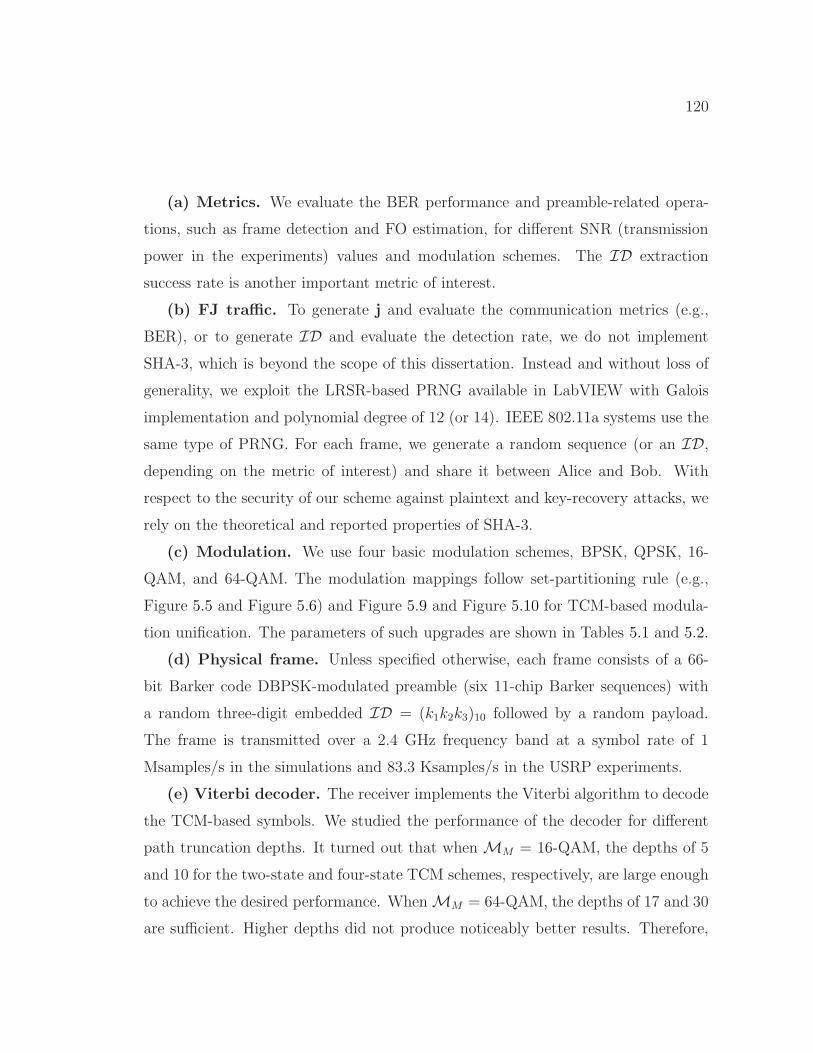
120
(a) Metrics. We evaluate the BER performance and preamble-related opera-
tions, such as frame detection and FO estimation, for different SNR (transmission
power in the experiments) values and modulation schemes. The ID extraction
success rate is another important metric of interest.
(b) FJ traffic. To generate j and evaluate the communication metrics (e.g.,
BER), or to generate ID and evaluate the detection rate, we do not implement
SHA-3, which is beyond the scope of this dissertation. Instead and without loss of
generality, we exploit the LRSR-based PRNG available in LabVIEW with Galois
implementation and polynomial degree of 12 (or 14). IEEE 802.11a systems use the
same type of PRNG. For each frame, we generate a random sequence (or an ID,depending on the metric of interest) and share it between Alice and Bob. With
respect to the security of our scheme against plaintext and key-recovery attacks, we
rely on the theoretical and reported properties of SHA-3.
(c) Modulation. We use four basic modulation schemes, BPSK, QPSK, 16-
QAM, and 64-QAM. The modulation mappings follow set-partitioning rule (e.g.,
Figure 5.5 and Figure 5.6) and Figure 5.9 and Figure 5.10 for TCM-based modula-
tion unification. The parameters of such upgrades are shown in Tables 5.1 and 5.2.
(d) Physical frame. Unless specified otherwise, each frame consists of a 66-
bit Barker code DBPSK-modulated preamble (six 11-chip Barker sequences) with
a random three-digit embedded ID = (k1k2k3)10 followed by a random payload.
The frame is transmitted over a 2.4 GHz frequency band at a symbol rate of 1
Msamples/s in the simulations and 83.3 Ksamples/s in the USRP experiments.
(e) Viterbi decoder. The receiver implements the Viterbi algorithm to decode
the TCM-based symbols. We studied the performance of the decoder for different
path truncation depths. It turned out that whenMM = 16-QAM, the depths of 5
and 10 for the two-state and four-state TCM schemes, respectively, are large enough
to achieve the desired performance. WhenMM = 64-QAM, the depths of 17 and 30
are sufficient. Higher depths did not produce noticeably better results. Therefore,

121
0 50 100 150 200 250Symbols Pair index
3.8
3.9
4
Em
piric
al p
df
×10-3
(a)Mi = BPSK
0 50 100 150 200 250Symbols Pair index
3.8
3.9
4
Em
piri
cal p
df
×10-3
(b)Mi = QPSK
0 50 100 150 200 250Symbols Pair index
3.8
3.9
4
Em
piri
cal p
df
×10-3
(c)Mi = 16-QAM
Figure 5.12: Empirical probability density functions of pairs of successive modulatedsymbols using MM = 16-QAM and different Mi’s. The input bit sequence isgenerated using uniform distribution.
the maximum decoding delay imposed by FCJ is bounded by 10-30 symbol times,
depending onMM .
5.6.1 Modulation Scheme Indistinguishability
It may be argued that the dependency (correlation) that is introduced by TCM
among successive MM -modulated symbols could be used by Eve to distinguish
between Mi-modulated symbols embedded in MM , Mi 6= MM , from true MM -
modulated symbols. To verify the indistinguishability property of our modulation
schemes unified by the proposed untraceable TCM, we employ Kolmogorov-Smirnov
(KS) statistical test to compare sequences ofMi-modulated symbols embedded in
MM constellation to the sequences of trueMM -modulated symbols. In particular,
we consider the empirical probability distributions (pdfs) of transmitted symbols as
well as pairs of successive symbols. The latter one is important because If Eve detects
any correlation between two successive symbols (provided that the information bits
are random), she may conclude that Mi 6= MM and may also be able to discern
Mi.
Without loss of generality, we considerMM = 16-QAM; hence, 256 pairs of sym-
bols. In Figure 5.12, we plot the empirical probability distributions of successive-
symbols pairs in a pool of 2× 10⁶ transmitted symbols when all bits in information

122
0 2 4 6 8 10 12γ (dB)
0
0.2
0.4
0.6
0.8
1
Prob
. Acc
urat
e Fr
ame
Det
ectio
n
BPSK, τ = 80, L = 4P-mod., τ = 80, L = 4P-mod., τ = 80, L = 6BPSK, τ = 64, L = 4P-mod., τ = 64, L = 4P-mod., τ = 64, L = 6
Figure 5.13: Impact of embedded ID onframe detection (emulations).
0 2 4 6 8 10 12SNR (dB)
10-4
10-3
10-2
10-1
100
Dig
it-E
rror
Rat
e in
ID
Ext
ract
ion δ
f = 0 Hz
δf = 5 kHz
Figure 5.14: Digit-error rate in ID de-tection vs. SNR (emulations).
and FJ sequences are randomly selected from a uniform distribution. At a confi-
dence level of 97.5%, the KS test approves that the three empirical pdfs are drawn
from the same (uniform) probability distribution function and so are indistinguish-
able. Because Alice uses onlyMM for transmission, Eve will think thatMM is the
underlying modulation scheme. By applyingMM to demodulate the symbols that
were originally modulated usingMi 6=MM , Eve’s estimate of the payload size will
be incorrect and further, BER will be maximum.
5.6.2 System Emulations
To assess the performance of individual components of FCJ, we decouple the unifi-
cation/encryption schemes from the message embedding approach. AWGN channel
model is considered to emulate frame transmission and reception. In the emulations,
FO is a controllable parameter, whereas in the experiments, it is a feature of the
USRP radio oscillator.
Identifier embedding
First, we consider the ID embedding scheme and study how much the superposi-
tion of ID onto the preamble affects frame detection and FO estimation accuracy.

123
Once the frame is detected, Bob uses the two identical halves of the preamble to
estimate ∆f and compensates for it before ID extraction. We also measure the per-
formance of the (uncoded) ID detection method at Bob in the presence of residual
FO estimation errors.
Frame detection is the first step in the decoding process. It starts by a threshold-
based energy detection, followed by the cross-correlation of the received samples r
against a series of the known Barker sequences. We assume that the average total
transmission power with and without an superposed ID onto the preamble is ex-
pected to be the same. Figure 5.13 shows that the power reduction for the original
preamble in our embedding scheme results in about 2 dB loss in frame detection;
irrespective of ∆f . Although three distinctly shifted Barker sequences (repeated
twice) generate additional message spikes and also Bob is still agnostic to the em-
bedded identifier, the highest of these spikes in the absence of noise and random
payload will not be more than 4% of the spike corresponding to the beginning of
the preamble (see Section 5.5.2).
Bob then moves on to the next phase; FO estimation. Even though the IDsuperposition in FCJ results in variable amplitudes for different symbols (in fact,
some of the symbols will have zero amplitude), the results (not shown here) show
that the symmetry between two parts of the ID-bearing signal helps Bob in main-
taining the same FO estimation performance without FCJ. The reason is that for
estimating ϕ(T ), the amplitude of the identical pairs is usually taken into account.
Therefore, the noise cannot dominate the FO estimation process in FCJ more than
default scheme.
While in current 802.11 systems Bob needs to successfully decode the sender’s
32-bit MAC address to decrypt an encrypted payload, in FCJ Bob needs error-free
extraction of the ID to generate j. In Figure 5.14 we show the digit-error rate
performance of our preamble-based identification scheme. Assuming that the IDsare uncoded, Bob needs to successfully detect all the l digits of an ID. The results
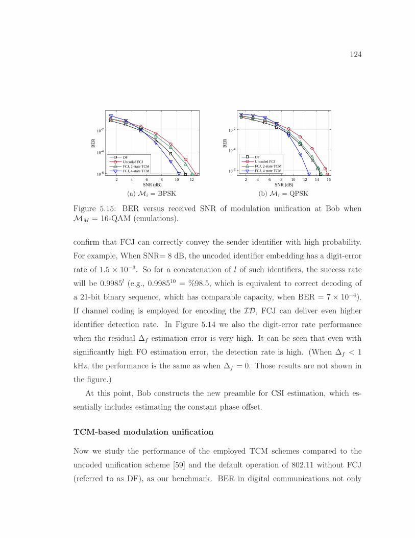
124
2 4 6 8 10 12SNR (dB)
10-6
10-4
10-2
BE
R
DFUncoded FCJFCJ, 2-state TCMFCJ, 4-state TCM
(a)Mi = BPSK
2 4 6 8 10 12 14 16SNR (dB)
10-6
10-4
10-2
BE
R
DFUncoded FCJFCJ, 2-state TCMFCJ, 4-state TCM
(b)Mi = QPSK
Figure 5.15: BER versus received SNR of modulation unification at Bob whenMM = 16-QAM (emulations).
confirm that FCJ can correctly convey the sender identifier with high probability.
For example, When SNR= 8 dB, the uncoded identifier embedding has a digit-error
rate of 1.5 × 10⁻³. So for a concatenation of l of such identifiers, the success rate
will be 0.9985l (e.g., 0.998510 = %98.5, which is equivalent to correct decoding of
a 21-bit binary sequence, which has comparable capacity, when BER = 7 × 10⁻⁴).
If channel coding is employed for encoding the ID, FCJ can deliver even higher
identifier detection rate. In Figure 5.14 we also the digit-error rate performance
when the residual ∆f estimation error is very high. It can be seen that even with
significantly high FO estimation error, the detection rate is high. (When ∆f < 1
kHz, the performance is the same as when ∆f = 0. Those results are not shown in
the figure.)
At this point, Bob constructs the new preamble for CSI estimation, which es-
sentially includes estimating the constant phase offset.
TCM-based modulation unification
Now we study the performance of the employed TCM schemes compared to the
uncoded unification scheme [59] and the default operation of 802.11 without FCJ
(referred to as DF), as our benchmark. BER in digital communications not only

125
2 4 6 8 10 12SNR (dB)
10-6
10-4
10-2
BE
R
DFUncoded FCJFCJ, 2-state TCMFCJ, 4-state TCM
(a)Mi = BPSK
2 4 6 8 10 12 14 16SNR (dB)
10-6
10-4
10-2
BE
R
DFUncoded FCJFCJ, 2-state TCMFCJ, 4-state TCM
(b)Mi = QPSK
4 6 8 10 12 14 16 18 20SNR (dB)
10-6
10-4
10-2
BE
R
DFUncoded FCJFCJ, 2-state TCMFCJ, 4-state TCM
(c)Mi = 16-QAM
Figure 5.16: BER versus received SNR of modulation unification at Bob whenMM = 64-QAM (emulations).
depends on SNR and dmin,i, but also on FO estimation accuracy. In order to focus
only on the impact of modulation encryption/unification, in this subsection, we
assume ∆f = 0 but Bob still have to correctly detect the frame and estimate the
CSI.
Figure 5.15 and Figure 5.16 depict the BER performance of FCJ as a function
of the SNR at Bob for different modulation schemesMi whenMM = 16-QAM and
64-QAM, respectively. When BPSK is embedded into 16-QAM (Figure 5.15(a)), the
two-state TCM scheme can alleviate to some extent the performance loss due to the
(uncoded) unification. However, using the four-state TCM scheme, Bob approaches
the asymptotic coding gain without leaking the original modulation scheme. Note
that if the underlying bit sequence belongs to the PHY-layer header with a known
modulation scheme (e.g., BPSK), Eve may be able to obtain the original (encrypted)
symbols but she still is not able to decrypt them because of our robust modulation
encryption. For the QPSK case in Figure 5.15(b), it can be observed that the two-
state TCM scheme can be sufficient for maintaining the performance of the default
operation with the minimum delay and complexity. This figure also verifies the
asymptotic gains calculated in Table 5.1.
The constellation of 64-QAM is denser than the one of 16-QAM. Therefore, when
MM = 64-QAM, the coding gain in general will be less than the case of MM =

126
16-QAM, as can be seen in Figure 5.16. For example, using the two-state TCM
forMi = QPSK is no longer sufficient in this case (Figure 5.16(b)). However, the
two-state TCM is good enough whenMi = 16-QAM (Figure 5.16(c)). As a general
rule, the higher the order ofMi is, less complex TCM codes can be sufficient. Alice
and Bob can agree upon the least complex but sufficient TCM codes for each Mi
to reduce the overall complexity.
5.6.3 USRP Experiments
We now exploit our USRPs, one acting as Alice and another as Bob, to evaluate
real transmissions in an indoor environment. The distance between Alice and Bob
is 2.2 m and we vary the transmission power. Alice and Bob each are equipped with
a 3 dB antenna. The noise level at the receiver is about −87 dBm. We assume that
the payload consists of 3200 symbols. This selection is to mimic a situation in which
Alice hides the true size of different frames by transmitting the frames with same
frame duration. Hence, when Mi = BPSK, QPSK, 16-QAM, and 64QAM, Alice
transmits 400, 800, 1600, and 2400 bytes, respectively. Using the same number of
symbols also makes the amount of phase offset errors comparable for differentMi’s.
In our empirical evaluations, we encountered a few challenges. First, the USRPs
truncates peaks of a signal with high PAPR (to avoid overflow) when the average
signal power necessities transmitting the peak at a power higher than the one set by
the user. In 16-QAM and 64-QAM, certain symbols (e.g., corners of the constellation
map, which result in high PAPR) are often truncated; resulting in several bit errors.
Compared to QPSK/BPSK, 64-QAM has 3.7 dB higher PAPR. To remedy this issue,
we scaled down the average power of generated samples at the transmitter to a level
that the USRPs can transmit the peak values without truncation. Furthermore, we
scale the sample sequences in all experiments to the same normalized average Tx
power. This solution is more reliable for comparison purposes than a solution in
which the peak value is always transmitted at the maximum power but the average

127
10-4 10-3.5 10-3 10-2.5 10-2 10-1.5 10-1 10-0.5
BER
0
0.2
0.4
0.6
0.8
1
F(x)
FCJ (QPSK)DF (QPSK)DF (64-QAM)
(a) Mi = QPSK and Tx power = −8 dBm(−1 dBm for 64-QAM)
10-4 10-3.5 10-3 10-2.5 10-2 10-1.5 10-1 10-0.5
BER
0
0.2
0.4
0.6
0.8
1
F(x)
FCJ, -4 dBmFCJ, -1 dBmDF, -4 dBmDF, -1 dBm
(b)Mi = 16-QAM
Figure 5.17: Empirical cumulative distribution function of BER (USRP results).
power varies from one frame to another.
The second challenge is inaccurate FO estimation. As reported in [58, 59] and
discussed in Section 5.4.2, the FO estimation is often inaccurate in hardware ex-
periments, which results in high BER for large frames. Denser modulation schemes
and asymmetric constellation maps are often more sensitive to FO estimation errors.
In FCJ, |Mi| symbols of a symmetric constellation are encoded to 2|Mi| symbols
and are asymmetrically distributed in the constellation ofMM . To reduce the esti-
mation error, we (1) increase the length of the preamble to better average out the
noise, and (2) maintained a coarse estimate of ∆f based on previous transmissions
and compensating for it before performing the normal FO estimation in each run
(similar to [58]). However, the estimate may still be inaccurate and result in high
BER. When averaging the BER of several transmissions, a (small) subset of BERs
with high values (e.g., 10−1) dominates the rest of lower BER values. Therefore,
we used CDF curves for comparing the performance of different schemes in order to
separate the BER values due to inaccurate FO estimation from the rest. Each CDF
represents the BERs of 2000 transmissions.

128
The third challenge is inaccurate frame detection when ∆f is high. The ∆f
between the two USRPs at 2.4 GHz carrier frequency varies between 0.6 kHz to
1.1 kHz. At Bob, the summation of the terms with time-varying phase offsets
during the preamble may reduce the value of (2.8). To address this problem, we
first try to detect the frame and then calculate an initial FO estimate using the two
correlation values with highest amplitude spikes in (2.8) before taking the absolute
value (similar to the method in [28]). The phase offset between these two values is
an estimate of the phase offset between two samples that are 11 samples away from
each other. After compensating for this initial estimate, Bob again performs frame
detection. Note that the embedded ID does not impact the phase offset between
the two values and so the performance of this method.
In analyzing the measured payload BER, we distinguish between cases based on
whether or not the frame or ID is correctly detected. Basically, any frame or IDdetection error will result in a packet drop and so we exclude these cases when mea-
suring the BER. Nevertheless, the single-digit detection rate in our experiments is
> 99% even if the transmission power is set to the minimum in our setup (−8 dBm).
In Figure 5.17, we compare the performance of FCJ with the four-state TCM
to the one of the default scheme. In our measurements, the SNR was high and
the decoding errors were mainly due to inaccurate FO estimation. Figure 5.17(a)
depicts the BER distribution whenMi = QPSK andMM = 64-QAM. In this case,
we set the Alice’s transmission power to its minimum. Even though the median
BER in both cases is the same (10−3.8), erroneous FO estimation and accumulation
of phase error in this case results in slightly worse performance compared to the
default scheme (as explained in Section 5.4.2). In the same figure, we also show the
performance of 64-QAM, which is significantly impacted by erroneous FO estima-
tion. However, our scheme performs better than the default scheme when Mi =
16-QAM (see Figure 5.17(b)). The reason is that the impact of residual FO estima-
tion errors on our scheme in this case is similar to its impact on 16-QAM. Moreover,
129
when the residual error is low, the TCM code helps Bob in FCJ to correct few bits in
error and achieve higher error-free transmissions. This can be seen in Figure 5.17(b)
for two different transmission powers. The median BER values for FCJ and the de-
fault scheme are 10−1.79 and 10−1.879, respectively, when the transmission power is
−4 dBm. These values when the transmission power is −1 dBm are 10−2.388 and
10−2.06, respectively.
5.7 Summary
Preventing the leakage of transmission attributes, including unencrypted
PHY/MAC header fields and the payload’s modulation scheme, is challenging. In
this paper, we proposed Friendly CryptoJam (FCJ), a combination of friendly jam-
ming and low-level encryption, to effectively protect the confidentiality of lower-layer
fields and prevent SCI-based traffic classification, rate-adaptation, plaintext, dictio-
nary, modulation detection, and device-based tracking attacks. FCJ employs three
main techniques. First, modulation-aware encryption is used to perfectly secure
plaintext headers and readily encrypted payload. Second, an energy-efficient and
indistinguishable modulation unification technique based on trellis-coded modula-
tion (TCM) is used to obfuscate the payload’s modulation scheme and partially
decorrelate the modulated-frame duration from the payload size. Third, a mes-
sage embedding technique is applied to overlay a frame-specific PHY-layer sender
identifier on the frame preamble, obviating the need for MAC address and facilitat-
ing session-key lookup at PHY layer. We showed theoretically and experimentally
that such an identifier that is constructed using a series of shifted Barker sequences
and is superposed it on the 802.11b preamble can be reliably detected at the re-
ceiver without considerably affecting typical preamble functions. The simulation
and experimental results also verify that modulation unification and encryption are
successful in hiding the true packet size, modulation scheme, and frame content
without degrading the BER performance.

130
CHAPTER 6
Exploiting Frame Preamble to Modulate
User-Information Bits in OFDM-based 802.11
Systems
6.1 Introduction
Wireless systems continue to boost their transmission speeds and enhance their
security. Among others, PHY layer techniques, including multi-user MIMO and
beamforming (e.g., [78,79]) for higher payload’s transmission rate and artificial noise
(e.g., [80]) for improved transmission security, have shown great promise. However,
in these wireless systems, the preamble is never utilized for conveying information
bits at the PHY layer; a feature that can facilitate new functionalities related to
enhanced performance and/or security. In a wireless system, the frame preamble is
a special signal prepended to the (modulated) PHY-layer header at the transmit-
ter (Tx) and is used by the receiver (Rx) to perform several PHY-layer functions.
These functions include frame detection, FO estimation, CSI estimation, dynamic
range estimation (used for automatic gain control (AGC) convergence), etc. In this
chapter, we consider the frame preamble in OFDM-based WiFi systems. The dura-
tion of this preamble in 802.11a [1] is 16 µs and can be up to 52 µs in 802.11n/ac
MIMO systems [24, 79], irrespective of the payload size and transmission rate. So
the preamble can take 0.5-10% of a frame duration depending on the number of bits
and the transmission rate of the payload. Because it is not designed to carry any
user-payload bits, the frame preamble in current systems is under-utilized.
In Section 5.5, we considered the preamble in non-OFDM (single carrier) sys-
131
tems for message embedding. In this chapter, however, we focus on the preamble of
widespread OFDM-based IEEE 802.11 systems (e.g., .11n/ac) and study the feasibil-
ity of carrying a sequence of random bits using this preamble. For the first time, we
exploit the potential of this preamble in modulating a bit sequence, while preserving
its basic properties (legacy receivers are still operate as normal). In OFDM-based
802.11 systems, the Rx needs to know the preamble “structure” but does not need
to know the exact signal of the whole preamble. We exploit this feature to construct
several new but legitimate preamble waveforms. Each waveform can represent the
modulated version of a bit sequence.
To generate the legitimate preamble waveforms, we design a novel modulation
technique called preamble modulation (P-modulation). P-modulation is a combi-
nation of two independent signal processing techniques, time shift in the time do-
main and phase rotation in the frequency domain. These techniques preserve the
key characteristics of a standard preamble. At the Rx and after applying channel
equalization to the received preamble signal, P-modulation exploits the particu-
lar dependency pattern among the subcarriers of legitimate preamble waveforms
as well as the mandatory repetitions in the preamble to efficiently distinguish be-
tween different waveforms and accordingly demodulate the embedded information
bits. Furthermore, P-modulation employs a fine-scale synchronization technique to
account for the sensitivity of its demodulator to timing errors. For the same level of
robustness to channel/device impairments as BPSK modulation, P-modulation can
embed up to 8 and 19 bits in the preamble for channel bandwidth of 20 MHz and
80 MHz (e.g., 802.11ac), respectively. More bits can be embedded if P-modulation
is contrasted to higher-order modulation schemes.
The rest of the chapter is organized as follows. In Section 6.2, we motivate
the significance of P-modulation by discussing various potential applications. In
Section 6.3, we provide background on preamble functions and the requirements
that must be met in a legitimate OFDM-based WiFi systems preamble. We then

132
introduce P-modulation and its related modulation/demodulation techniques in Sec-
tion 6.4. The robustness of this scheme to channel/device impairments and its pos-
sible extensions to MIMO systems are discussed in Sections 6.5 and 6.6, respectively.
Finally, we present the results of extensive simulations and USRP experiments in
Section 6.7. The chapter is concluded in Section 6.8.
6.2 Applications of P-modulation
Embedding/modulating information in the frame preamble opens the door for sev-
eral important applications. We divide these applications into two categories: Se-
curity and PHY-layer signaling.
1) Security– The bit sequence embedded in the preamble can be used to repre-
sent a (time-varying) PHY-layer sender identifier, hence, facilitating full PHY-level
frame encryption and preventing MAC spoofing attacks. It can also represent the
sender’s time-varying digital signature (used to authenticate a link and prevent
copycat/replay attacks [81]) or the initialization vector for generating secret pilot
subcarriers locations (to mitigate pilot tone jamming attacks [82, 83]). As an ex-
ample of a use case, we now discuss using the embedded information for PHY-layer
sender identification.
Sender identification is a key functionality in any wireless network. It allows the
Rx to distinguish between different transmitting nodes. Moreover, if nodes employ
full-frame encryption for data confidentiality, sender identification is required at the
Rx before the decryption can take place so as to look up the right decryption key.
In this case, the Rx needs to receive a plaintext sender identifier at some header in
the protocol stack before it can start the decryption process. For example, in IEEE
WLAN standards, the globally unique MAC address at the link layer acts as the
sender identifier. However, a link-layer identifier is extracted only after decoding the
PHY-layer header. Thus, if the full frame is to be encrypted (including the PHY
header), the MAC address cannot be used to look up the decryption key. In other
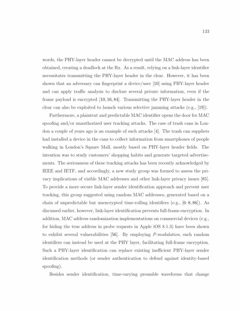
133
words, the PHY-layer header cannot be decrypted until the MAC address has been
obtained, creating a deadlock at the Rx. As a result, relying on a link-layer identifier
necessitates transmitting the PHY-layer header in the clear. However, it has been
shown that an adversary can fingerprint a device/user [10] using PHY-layer header
and can apply traffic analysis to disclose several private information, even if the
frame payload is encrypted [10, 16, 84]. Transmitting the PHY-layer header in the
clear can also be exploited to launch various selective jamming attacks (e.g., [19]).
Furthermore, a plaintext and predictable MAC identifier opens the door for MAC
spoofing and/or unauthorized user tracking attacks. The case of trash cans in Lon-
don a couple of years ago is an example of such attacks [4]. The trash can suppliers
had installed a device in the cans to collect information from smartphones of people
walking in London’s Square Mall, mostly based on PHY-layer header fields. The
intention was to study customers’ shopping habits and generate targeted advertise-
ments. The seriousness of these tracking attacks has been recently acknowledged by
IEEE and IETF, and accordingly, a new study group was formed to assess the pri-
vacy implications of visible MAC addresses and other link-layer privacy issues [85].
To provide a more secure link-layer sender identification approach and prevent user
tracking, this group suggested using random MAC addresses, generated based on a
chain of unpredictable but unencrypted time-rolling identifiers (e.g., [6–8, 86]). As
discussed earlier, however, link-layer identification prevents full-frame encryption. In
addition, MAC address randomization implementations on commercial devices (e.g.,
for hiding the true address in probe requests in Apple iOS 8.1.3) have been shown
to exhibit several vulnerabilities [56]. By employing P-modulation, such random
identifiers can instead be used at the PHY layer, facilitating full-frame encryption.
Such a PHY-layer identification can replace existing inefficient PHY-layer sender
identification methods (or sender authentication to defend against identity-based
spoofing).
Besides sender identification, time-varying preamble waveforms that change

134
from one frame to another can be used to counter against FO estimation attacks
(e.g., [36]). These attacks exploit the publicly known preamble signal to craft a
jamming signal that efficiently disrupts the FO estimation process at the Rx.
2) PHY-layer Signaling– P-modulation can be used as a signaling mechanism for
certain PHY-layer operations, which otherwise requires modifying existing header
structures and introducing new fields. For example, the embedded bit sequence can
be used to convey the operation mode of the Tx in full-duplex communications (e.g.,
transmit/receive vs. transmit/sense), the (time-varying) pattern of traveling pilots
proposed for the upcoming IEEE 802.11ah standard to improve channel estimation
under high Doppler scenarios [87], the modulation scheme of the PHY-layer header
to enable the Tx to use a higher transmission rate for this header, or any PHY-
layer field required for future applications that cannot be conveyed in the standard
PHY-layer header. Alternatively, the embedded bits can be a part of the PHY
header, merged into the preamble and removed from the frame (to reduce the frame
duration). Such an approach increases the utilization of the frame by communicating
a part of it through the preamble.
6.3 Preliminaries – STF Requirements
Before introducing P-modulation, we first explain the key operations and special
characteristics based on which the preamble of an OFDM-based IEEE 802.11 frame
is designed. The preamble consists of two fields [1,24]: a short training field (STF),
which consists of 10 repetitions of some periodic short training signal (STS), and
a long training field (LTF), which includes two repetitions of another periodic long
training signal (see Figure 6.1 for the preamble of a 20 MHz channel). The signal in
the STF is constructed by transmitting only on subcarriers that are four subcarrier-
spacings apart from each other, resulting in a larger greatest common divisor (gcd)
of the subcarrier frequencies than the gcd of the LTF subcarrier frequencies and so
a shorter time period. The preambles in 802.11n and 802.11ac (MIMO) standards

135
Figure 6.1: Preamble structure and subcarriers in 802.11a. si refers to the ithsubcarrier in the STF, i ∈ {−6, . . . , 6}/{0}.
are similar to 802.11a but are transmitted over a wider bandwidth (up to 160 MHz).
They may also include an additional STF for better AGC and multiple LTFs for
channel sounding and backward compatibility. After performing STF functions
(described below), LTS is used for CSI and fine FO estimation; hence, it must be
fully known to the Rx. On the other hand, the STF does not need to be fully known
to the Rx, as will be discussed next.
6.3.1 STF Functions
The STF is used for frame detection, coarse FO estimation, AGC, diversity selection,
and other functions. Accurate frame detection and FO estimation are two key
operations that require two identical signals in the STF (e.g., two STSs). Having
identical signals enables the Rx to detect the frame without knowing the channel.
Let h(t) represent the channel between the Tx and the Rx, and let x(t) be the
transmitted signal at time t. (The noise term is excluded in our discussion to simplify

136
the presentation.) In autocorrelation-based frame detection, the Rx needs only to
know the period, denoted by λS, of the STF signal to perform frame detection [26].
It searches for identical STSs by correlating two parts of the same received signal
h(t)x(t) that are separated by a time lag that equals to a multiple of λS. Let Aτ (t)
be the autocorrelation value at time t and time lag τ :
Aτ(t) =τ−1∑
n=0
h∗(t+n) h(t+τ+n) x∗(t+n) x(t+τ+n)∑τ−1q=0 |h(t+τ+q) x(t+τ+q)|2
(6.1)
where the time unit of the integer values λS, τ , and n is the sampling period at the
Rx. The time at which Aτ peaks is taken as the start of the frame.1 Assuming the
channel does not change during the STF, this method is channel-independent. It is
adopted in practical systems.
The other key function of the STF is FO estimation. FO refers to the inherent
difference in the operating frequencies of two oscillators. It creates a time-varying
phase offset in the received signal, and can significantly harm the performance of an
OFDM system [26]. To estimate the FO after determining the start of the STF, the
Rx considers samples that belong to two consecutive STSs and measures the phase
difference between the corresponding samples in these two STSs. The average of
the phase differences captures the FO between the two devices.
6.3.2 STF Requirements
The STF in current IEEE standards (as defined in [1]) is designed to satisfy certain
requirements related to the preamble functions. Any modification in this design
should take these requirements into account. In the following, we discuss these
requirements and explain how the current STF design satisfies them.
1To account for noise, in practical systems the first time that Aτ exceeds a near-to-maximumthreshold is taken as the frame start time. If this instance is a few samples before the true starttime, the Rx can use the known LTF signal to fine-tune the estimation.

137
Periodicity
In 802.11a, an OFDM symbol consists of 64 orthogonal frequency subcarriers (up to
256 subcarriers in 802.11n and 802.11ac). Without considering the guard interval,
the symbol lasts for 3.2µs. Twelve subcarriers are not used (see the null subcarriers
in Figure 6.1). The period λS of an STS is set to 3.2/4 = 0.8µs by using only 12
equally-spaced subcarriers out of 52 active ones. This enables the Rx to cover a
wide range of FOs, up to 625 kHz [88]. In addition, autocorrelation-based frame
detection and FO estimation rely on identical repetitions of the same STS. So all
the ten STSs should be identical.
Let S = [s−6, . . . , s−1, s1, . . . , s6] be the symbol sequence carried in these 12
subcarriers. Let P (t) be the value of the STF signal at time t. Then,
P (t) =6∑
k=−6,k 6=0
ske2πj(4k)∆f t, for t ∈ [0, 8µs] (6.2)
where ∆f is the frequency spacing between any two subcarriers in the original 64
subcarriers.
si s−6 s
−5 s−4 s
−3 s−2 s
−1 s1 s2 s3 s4 s5 s6Value 1 + j −1− j 1 + j −1− j −1− j 1 + j −1− j −1− j 1 + j 1 + j 1 + j 1 + j
Table 6.1: Sequence of QPSK-modulated symbols used to generate STF in802.11a/g [1]. |s−6| = |s−5| = . . . = |s6| =
√2. This sequence is then multiplied by√
13/6 to normalize the average power of the resulting symbols.
Peak-to-average Power Ratio (PAPR)
Due to the nonlinearity of power amplifier at the Tx, the PAPR of the STF, denoted
by RPAP, should be as small as possible to avoid poor transmission. IEEE 802.11a/-
n/ac standards use a set of 12 QPSK-modulated symbols for the sequence S (as
shown in Table 6.1), which achieves RPAP = 2.24 dB in 802.11a/g [88]. These symbols

138
are multiplied by a factor of√13/6 to normalize the average power of the STF with
respect to the rest of the frame [1].
Dynamic range
The STF is also used for AGC convergence. In order to accelerate AGC locking
and adjusting the reference signal value for the A/D converter at the Rx, the whole
dynamic range of the STF, denoted by RDR, should be covered by the A/D con-
verter resolution and without any overflow/underflow [88]. The RDR for the symbol
sequence shown in Table 6.1 is 7.01 dB, one of the lowest possible dynamic values
among the ones of all symbol sequences S that have low RPAP. In HT-mixed for-
mat of 802.11n, an additional STF is used to improve AGC estimation in MIMO
systems [24].
Θi θ1 θ2 θ3 θ4 θ5 θ6 θ7 θ8 θ9 θ10 θ11 b2b1i = 1 0 0 0 π 0 π π 0 π π π 00i = 2 π/2 π/2 π/2 −π/2 π/2 0 −π/2 π/2 −π/2 −π/2 −π/2 01i = 3 π π π 0 π π 0 π 0 0 0 11i = 4 −π/2 −π/2 −π/2 π/2 −π/2 0 π/2 −π/2 π/2 π/2 π/2 10
Table 6.2: Dependency patterns among all possible combinations of QPSK-modulated symbols in S that satisfy the STF requirements. The IEEE standarduses the dependency pattern Θ3 and ϕ = 0 when s−6 = 1 + j.
6.4 Proposed Preamble-Modulation Scheme
We now introduce P-modulation and show how it modulates (embeds) a bit sequence
in the STF of the preamble at the Tx and then demodulates (extracts) this sequence
at the Rx with low complexity and very little impact on normal preamble functions
(for backward compatibility with legacy receivers).

139
time (µs)0 0.2 0.4 0.6 0.8
|Pϕ(t)|
0.06
0.08
0.1
0.12
0.14
ϕ = 0ϕ = 3π/4
(a) Θ1
time (µs)0 0.2 0.4 0.6 0.8
|Pϕ(t)|
0.06
0.08
0.1
0.12
0.14
ϕ = 0ϕ = 3π/4
(b) Θ2
time (µs)0 0.2 0.4 0.6 0.8
|Pϕ(t)|
0.06
0.08
0.1
0.12
0.14
ϕ = 0ϕ = 3π/4
(c) Θ3
time (µs)0 0.2 0.4 0.6 0.8
|Pϕ(t)|
0.06
0.08
0.1
0.12
0.14
ϕ = 0ϕ = 3π/4
(d) Θ4
Figure 6.2: Amplitudes of the four STFs generated using the patterns in Table 6.2.(Only one STS is shown.)
6.4.1 Sequence Modulation
In our design, modulating a bit sequence is different from conventional digital mod-
ulation, where every element in the sequence of modulated symbols is determined
independently by one or multiple input bits. Instead, we use a particular “chain”
of correlated symbols to modulate a bit sequence. The correlation among symbols
in S is imposed by the RPAP and RDR requirements stated above. In the following,
we say a signal is STF-compliant if it satisfies all the requirements in Section 4.2.
The number of distinct STF-compliant signals determines the number of different
bit sequences that can be embedded in the STF.
To construct a set of STF-compliant sequences, we first identify different depen-
dency patterns among the symbols in S of known compliant signals. Using those
patterns, we then employ two signal processing techniques to generate as many com-
pliant signals as possible. In here, a dependency pattern is defined as the sequence
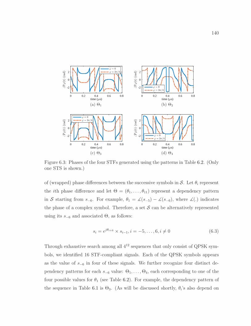
140
time (µs)0 0.2 0.4 0.6 0.8
6Pϕ(t)(rad)
-2
0
2ϕ = 0ϕ = 3π/4
(a) Θ1
time (µs)0 0.2 0.4 0.6 0.8
6Pϕ(t)(rad)
-2
0
2
ϕ = 0ϕ = 3π/4
(b) Θ2
time (µs)0 0.2 0.4 0.6 0.8
6Pϕ(t)(rad)
-2
0
2ϕ = 0ϕ = 3π/4
(c) Θ3
time (µs)0 0.2 0.4 0.6 0.8
6Pϕ(t)(rad)
-2
0
2
ϕ = 0ϕ = 3π/4
(d) Θ4
Figure 6.3: Phases of the four STFs generated using the patterns in Table 6.2. (Onlyone STS is shown.)
of (wrapped) phase differences between the successive symbols in S. Let θi representthe ith phase difference and let Θ = (θ1, . . . , θ11) represent a dependency pattern
in S starting from s−6. For example, θ1 = ∡(s−5) − ∡(s−6), where ∡(.) indicates
the phase of a complex symbol. Therefore, a set S can be alternatively represented
using its s−6 and associated Θ, as follows:
si = ejθi+6 × si−1, i = −5, . . . , 6, i 6= 0 (6.3)
Through exhaustive search among all 412 sequences that only consist of QPSK sym-
bols, we identified 16 STF-compliant signals. Each of the QPSK symbols appears
as the value of s−6 in four of these signals. We further recognize four distinct de-
pendency patterns for each s−6 value: Θ1, . . . ,Θ4, each corresponding to one of the
four possible values for θ1 (see Table 6.2). For example, the dependency pattern of
the sequence in Table 6.1 is Θ3. (As will be discussed shortly, θi’s also depend on

141
θ1.)
To design more compliant signals using the same dependency patterns Θi, i =
1, . . . , 4, we exploit the fact that if the symbols transmitted on the subcarriers of an
OFDM symbol are all shifted in phase by the same amount, then the period, the
RPAP, and the RDR of that OFDM symbol do not change. Hence, we can use higher-
order PSK symbols as s−6. To illustrate, let ϕ be the phase shift of the elements in
S and Pϕ(t) be the new STF after this shift. Then,
Pϕ(t) = ejϕP (t). (6.4)
Multiplying a signal by a constant coefficient does not change the ratio of the max-
imum and minimum amplitude of the signal (i.e., the RDR) or the ratio of the max-
imum and the root-mean-square of the signal (i.e., the RPAP). So the Tx can select
any phase for s−6 and the same amplitude of√2, follow one of the patterns Θi,
i = 1, . . . , 4, to define the rest of the symbols in S, and generate a STF-compliant
signal.
In Figure 6.2, we show the amplitudes of the STF-compliant signals, constructed
by using two different values for ϕ and one of the four dependency patterns. These
figures also show that Pϕ(t) and P (t) with the same dependency pattern have the
same envelope. Hence, amplitude-based STF functions (e.g., frame detection and
FO estimation) will not be impacted by the phase shift. The specific selection of
the dependency pattern Θ3 in the IEEE 802.11 standards is with respect to cross-
correlation-based detection issues (e.g., matched filter performance in the boundary
region between the STF and the LTF [89]). However, by using the autocorrelation
method for frame detection at the Rx, those issues will not be binding for our
scheme.
The coefficient ejϕ rotates the constellation map of the symbols in S by ϕ degrees.
Therefore, the set of s−6 values that can be used to generate STF-compliant signals

142
consists of the symbols of a PSK modulation scheme. The order of this modulation
scheme, denoted by M , depends on the performance of the PSK demodulation
operation and the accuracy of pattern detection (discussed in Section 6.4.2), as well
as the accuracy of CSI and FO estimation (discussed in Section 6.5). The order
specifies how many bits can be modulated using different constellation rotations
when using the same pattern. We refer to these log2 M bits as rotation bits. The Rx
can exploit the correlation among the symbols in S and use all of them to improve
the demodulation accuracy. However, incorrect detection of the underlying pattern
may significantly change the expected sequence of phases. This can be seen in
Figure 6.3, where we plot the phases of the signals in Figure 6.2.
A closer look at the patterns in Table 6.2 reveals that they are indeed not in-
dependent and a pattern Θi can be calculated by adding a multiple of π/2 to Θ1
(for θ6 a multiple of π should be added). For example, Θ2 = Θ1 + π/2. In other
words, when the phase differences between successive symbols of the frequency sub-
carriers are changed by a constant, the resulting signal remains a STF-compliant
signal. This property in the frequency domain has an interpretation in the time
domain: In OFDM systems, a time shift in the signal results in a linear phase shift
in the symbols along the ordered subcarriers [90]. Because the elements in S are
ordered by their frequencies, such a linear shift brings about the same change in
phase differences θi, i = 1, . . . , 11. This amount of change is indeed the slope of a
line that defines a symbol’s phase shift with respect to its frequency. Let N be the
number of samples in a symbol and ν be the line slope. The corresponding time
shift ts (in terms of the number of samples) is ts = N × ν/2π. For example, the
dependency patterns in Table 6.2 represent different amounts of time shift of the
same signal, as shown in Figure 6.2. Note that a time shift in a periodic signal does
not change its dynamic range and PAPR values. Therefore, we can generate other
sets of STF-compliant signals by shifting one compliant signal in time, or equiva-
lently, using different dependency patterns Θ(ν) = Θ1+ ν, ν ∈ [−π, π]. For example,
143
Θ2 in Table 6.2 can be represented by Θ(π/2). A time shift, however, impacts the
frame detection accuracy because the last few samples in the STF can have higher
amplitudes than the ones in the standard STF. This will inflate the noise samples
located before the true start of the frame during the frame detection when the au-
tocorrelation window includes a few of them. We exploit the LTF to account for
such errors.
We note that using different dependency patterns with the same ϕ is equivalent
to a form of frequency-domain differential PSK (FD-DPSK), which is robust to
channel phasor and FO estimation errors (i.e., a non-coherent scheme). The number
of different dependency patterns in our scheme, denoted by Q, depends on the target
performance of the demodulator (discussed in Section 6.4.2) and the frame detection
accuracy (discussed in Section 6.5). With the same ϕ, we can encode log2Q bits.
We show an example in Table 6.2 for Q = 4. In P-modulation, the assignment of
bits to patterns and phase shifts follows the Gray Coding rule.
Altogether, the Tx can embed the total of log2M + log2Q bits in the STF by
using the proposed time shift and phase rotation techniques simultaneously. So, the
bit sequence will be as follows:
[blogMQ, . . . , b1+logQ︸ ︷︷ ︸
ϕ
blogQ, . . . b1︸ ︷︷ ︸ν
](6.5)
6.4.2 Sequence Demodulation
The process of message extraction involves detecting the most probable symbols se-
quence carried on the 12 subcarriers of the STF. In contrast to digital demodulation,
in which the most probable symbols are independently identified to obtain the bit
sequence, in here a sequence of symbols should be detected simultaneously.
To demodulate and extract the embedded bit sequence, the Rx exploits the
correlation among the symbols that belong to the same STS as well as the repetition
of the STSs. It needs a small memory to first store the 10×16 received STF samples.
144
0 20 40 60 80 100
Phase difference (θ) index
-3
-2
-1
0
1
2
3
ν(rad
)
Figure 6.4: 99 phase differences among 12 × 9 = 108 symbols extracted from 9STSs. The Tx uses 16-DPSK and the Rx detects ν = 3π/16 using MMSE estimator(γ = 3dB).
After compensating for the FO and equalizing the effect of the LTF-based estimated
CSI on these samples, it applies the 16-point discrete Fourier transform (DFT) on
each of the STSs and obtain the symbols on each subcarrier. Then, it estimates ν.
Let Sl = [sl,−6, . . . , sl,−1, sl,1, . . . , sl,6], l ∈ {1, . . . , 9}2 be the sequence received on the
lth STS and ν be the most probable estimate of ν based on S. Because the elements
in S are correlated, we use minimum mean-square error (MMSE) to estimate ν with
respect to Θ1. An example drawn from our experiments is shown in Figure 6.4. Next,
to find an estimate of ϕ, denoted by ϕ, the Rx subtracts the phases of the reference
elements constructed according to Θ(ν) from the corresponding elements in Sl, l =1, . . . , 9. To account for noise when measuring the phase, the Rx calculates the sum
of all 12l elements. The estimation of ν requires accurate frame detection while the
estimation of ϕ needs accurate FO and CSI estimation. After FO correction and
channel equalization, the bit sequence is fully demodulated based on ν and ϕ.
To study the limit on the order of the PSK modulation used for constellation
rotation (the minimum phase by which a sequence is shifted) and the number of
2We cannot rely on all ten STSs because the last one may not be the same as other STSs dueto pulse shaping in its boundary with the LTF.

145
different time shifts Q (equivalently, the number of different Q-DPSK patterns),
we target a performance for our scheme that is comparable to the performance
of the most reliable modulation scheme supported by the system, which is often
used for transmitting the PHY header. This will guarantee that whenever the PHY
header can be successfully decoded, the embedded bit sequence can also be extracted
successfully. In 802.11, BPSK is the most reliable modulation scheme.
The performance of demodulating a sequences of modulated symbols depends
on the signal-to-noise ratio (SNR), FO and CSI estimation accuracy, and frame
detection accuracy. In this section, we assume an AWGN channel model as well as
accurate FO and frame detection to obtain the M and Q that result in the same
BER as BPSK. Let B2(γ) be the BER of 2-PSK (BPSK). Then, B2(γ) = Q(√
2γ),
where Q(.) is the Q-function and γ denotes the SNR. The Rx first estimates Θ(ν)
followed by estimating ϕ.
Pattern Detection
The pattern Θ(ν), modulated using FD-DPSK, is the base for the estimation of
the other parameter ϕ. Let the BER of frequency-domain Q-DPSK modulation
be BDQ (γ). When the channel is flat-flat fading, the BER performance of DPSK
is the same, irrespective of whether it is time-domain or frequency domain [91].
However, FD-DPSK performs worse than the time-domain DPSK when the channel
is frequency-selective/time-dispersive [91]. The expression of the BER under an
AWGN channel is provided in Equation 8.86 of [92], but it does not have a closed-
form. Instead, we use the MATLAB function berawgn, which uses a very close
expression to the one in [92], to numerically find the maximum Q that satisfies
BDQ (γ) ≤ B2(γ). (DPSK modulation scheme loses 3 dB in gain compared to PSK
due to the subtraction of two random variables.)
The amplitude of a symbol in the STF is√13/3 times the one of a BPSK-
modulated symbol in the frame payload. In addition, l = 9 STFs, which corresponds
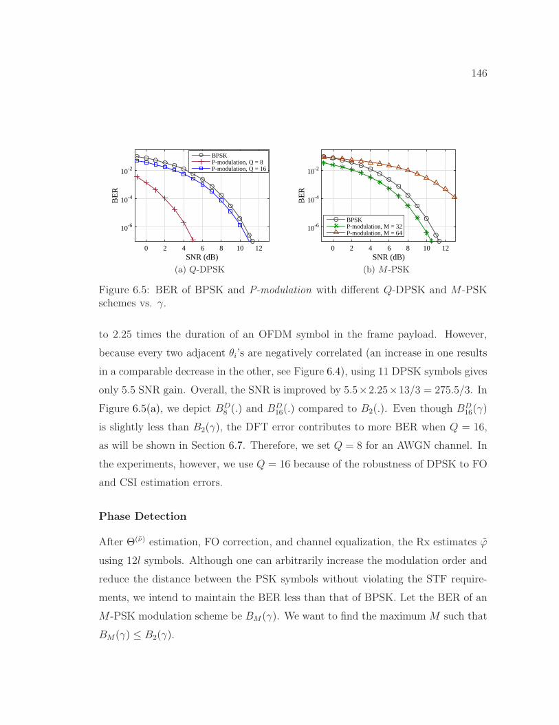
146
SNR (dB)0 2 4 6 8 10 12
BE
R
10-6
10-4
10-2
BPSKP-modulation, Q = 8P-modulation, Q = 16
(a) Q-DPSK
SNR (dB)0 2 4 6 8 10 12
BE
R
10-6
10-4
10-2
BPSKP-modulation, M = 32P-modulation, M = 64
(b) M -PSK
Figure 6.5: BER of BPSK and P-modulation with different Q-DPSK and M-PSKschemes vs. γ.
to 2.25 times the duration of an OFDM symbol in the frame payload. However,
because every two adjacent θi’s are negatively correlated (an increase in one results
in a comparable decrease in the other, see Figure 6.4), using 11 DPSK symbols gives
only 5.5 SNR gain. Overall, the SNR is improved by 5.5×2.25×13/3 = 275.5/3. In
Figure 6.5(a), we depict BD8 (.) and BD
16(.) compared to B2(.). Even though BD16(γ)
is slightly less than B2(γ), the DFT error contributes to more BER when Q = 16,
as will be shown in Section 6.7. Therefore, we set Q = 8 for an AWGN channel. In
the experiments, however, we use Q = 16 because of the robustness of DPSK to FO
and CSI estimation errors.
Phase Detection
After Θ(ν) estimation, FO correction, and channel equalization, the Rx estimates ϕ
using 12l symbols. Although one can arbitrarily increase the modulation order and
reduce the distance between the PSK symbols without violating the STF require-
ments, we intend to maintain the BER less than that of BPSK. Let the BER of an
M-PSK modulation scheme be BM (γ). We want to find the maximum M such that
BM(γ) ≤ B2(γ).

147
Similar to the previous case, the amplitude of a PSK-modulated symbol in the
STF is√
13/3 times the one of a BPSK-modulated symbol. The summation of
12 i.i.d random variables with Gaussian noise improves the SNR by 12. The noise
variance is further decreased by using l = 9 repetitions of the same STS. Because
the duration (power) of nine STSs is 2.25 times the duration (power) of a BPSK-
modulated symbol in the preamble, the overall SNR improvement will be 12×2.25×13/3 = 351/3. An approximation of the BER for M-PSK is given by:
BM(γ) =2
log2MQ(√
2γ sin π/M). (6.6)
Numerically solving for the maximum M that satisfies
2
log2MQ(√
2× 351× γ/3 sin π/M)≤ Q
(√2γ
), (6.7)
we obtain M = 25 = 32∀γ ∈ R, and M = 26 = 64∀γ ≤ 0.2 dB (see Figure 6.5(b)).
6.4.3 Noncompliant but Possible STF Waveforms
In the scheme above, all the STF requirements, including RPAP ≤ 2.24 dB and
RDR ≤ 7.01 dB, are met. However, modern wireless devices are capable of processing
signals with higher RPAP and RDR values. For example, COTS wireless routers
usually support RDR > 100 dB. This paves the way to expand the set Θ and include
several new patterns by identifying STF waveforms whose RPAP and RDR values
are close to the ideal values, i.e., almost-compliant sequences. For example, if we
allow RPAP to increase to 2.95 dB, two new independent sets of patterns will become
available in addition to the set Θ(ν) defined above.
Moreover, by expanding the search space for si’s of STF-compliant signals be-
yond QPSK, one may find other types of dependency patterns. Considering 8-PSK,
for example, we identified at least one new pattern (in addition to the patterns that
define the sequences with only QPSK symbols). For this pattern, RPAP ≤ 2.27 dB

148
and RDR ≤ 12 dB, which are close to the target ideal values.
6.5 Effects of Channel/Device Impairments on P-modulation
The sequence demodulation process explained above is impacted by the complex
channel coefficient h, the residual FO estimation, and the frame detection errors.
In this section, we study the effect of each of these parameters and discuss the
robustness of time shift and constellation rotation techniques against them. Let δf
and tE represent the FO (normalized to ∆f) and the timing error (in number of
samples), respectively.
6.5.1 Tx-Rx Channel Coefficients
First, we consider the effect of the channel on the dependency pattern Θ(ν). Let
hl,k, k = −6, . . . , 6(k 6= 0), l = 2, . . . , 9 be the channel coefficient on each STF
subcarrier during the lth STS. Assuming δf = 0 and tE = 0, the symbol sk on the
lth STS at the Rx, denoted by sl,k, will be:
sl,k = hl,ksk + nk. (6.8)
where nk is the noise component.
To detect the dependency pattern, the Rx calculates the phase difference between
each pair of adjacent subcarriers. If the channel’s coherence bandwidth is larger than
the signal’s bandwidth, hence the hl,k’s will have the same phase value, the channel
does not impact the phase differences θi. On the other hand, if the coherence
bandwidth is very small and the phases of hl,k’s are uncorrelated, the variations will
be averaged out when MMSE is used. In the case of neither small nor large coherence
bandwidth, the Rx treats each period of coherence bandwidth independently. For
each set of subcarriers with the same hl,k’s, the Rx computes θi’s separately. The
same argument can be made for multi-path channels. Furthermore, because the

149
proposed demodulator treats STSs independently, θi’s are not affected if the channel
is fast fading/time-selective (provided that the coherence time is larger than λS).
Similarly, when δf 6= 0, the subcarriers that belong to the same STS will ex-
perience the same amount of phase offset and so residual FOs do not impact the
decoding performance. However, FD-DPSK is susceptible to timing errors. We
remedy that by taking advantage of the LTF (see below).
Although the channel has little impact on ν, it may significantly change the
phase of the PSK symbols in S by a constant, i.e., the channel phasor. So the Rx
needs to estimate the channel and equalize it before estimating ϕ.
6.5.2 Frame Detection Accuracy
A time offset in the time domain manifests itself as a linear phase shift in the
frequency domain [38,90]. This phase shift varies linearly with the subcarrier index
and may significantly change the phase differences between successive symbols in S.The timing error tE will create phase shift νk in the kth subcarrier:
νk =2πktEN
, k = −N/2, . . . , N/2. (6.9)
Figure 6.6 depicts an example (drawn from our experiments) of the linear change
of (wrapped) estimated channel phases with the subcarrier frequency when frame
detection is not accurate. A linear phase shift in the frequency domain will itself
result in a constant phase change 2πtE/N in the pattern Θi. For example, if tE =
4, N = 16, and Θ1 in Table 6.2 are used for each STS, the Rx will detect Θ2
because Θ2 = Θ1+π/2. Hence, correct detection of the pattern depends on accurate
detection of the STF.
In P-modulation, we take advantage of time-domain LTF-based CSI estimation to
fine-tune the frame detection. The Rx usually considers a channel estimation period
of length, say L, to estimate the maximum of L multi-path channel components.
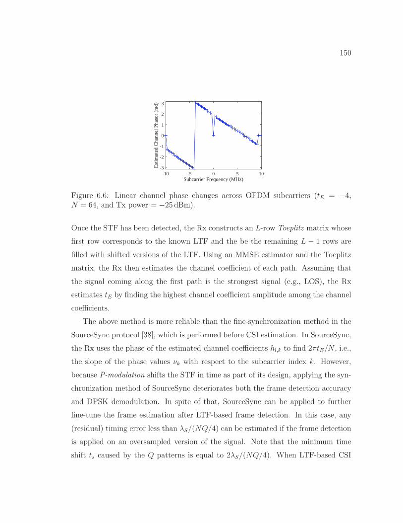
150
Subcarrier Frequency (MHz)-10 -5 0 5 10
Est
imat
ed C
hann
el P
haso
r (r
ad)
-3
-2
-1
0
1
2
3
Figure 6.6: Linear channel phase changes across OFDM subcarriers (tE = −4,N = 64, and Tx power = −25 dBm).
Once the STF has been detected, the Rx constructs an L-row Toeplitz matrix whose
first row corresponds to the known LTF and the be the remaining L − 1 rows are
filled with shifted versions of the LTF. Using an MMSE estimator and the Toeplitz
matrix, the Rx then estimates the channel coefficient of each path. Assuming that
the signal coming along the first path is the strongest signal (e.g., LOS), the Rx
estimates tE by finding the highest channel coefficient amplitude among the channel
coefficients.
The above method is more reliable than the fine-synchronization method in the
SourceSync protocol [38], which is performed before CSI estimation. In SourceSync,
the Rx uses the phase of the estimated channel coefficients hl,k to find 2πtE/N , i.e.,
the slope of the phase values νk with respect to the subcarrier index k. However,
because P-modulation shifts the STF in time as part of its design, applying the syn-
chronization method of SourceSync deteriorates both the frame detection accuracy
and DPSK demodulation. In spite of that, SourceSync can be applied to further
fine-tune the frame estimation after LTF-based frame detection. In this case, any
(residual) timing error less than λS/(NQ/4) can be estimated if the frame detection
is applied on an oversampled version of the signal. Note that the minimum time
shift ts caused by the Q patterns is equal to 2λS/(NQ/4). When LTF-based CSI
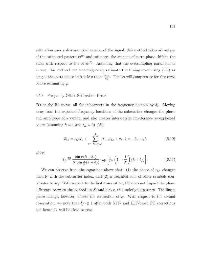
151
estimation uses a downsampled version of the signal, this method takes advantage
of the estimated pattern Θ(ν) and estimates the amount of extra phase shift in the
STSs with respect to θi’s of Θ(ν). Assuming that the oversampling parameter is
known, this method can unambiguously estimate the timing error using (6.9) as
long as the extra phase shift is less than 2πtE2Q
. The Rx will compensate for this error
before estimating ϕ.
6.5.3 Frequency Offset Estimation Error
FO at the Rx moves all the subcarriers in the frequency domain by δf . Moving
away from the expected frequency locations of the subcarriers changes the phase
and amplitude of a symbol and also creates inter-carrier interference as explained
below (assuming h = 1 and tE = 0) [93]:
sl,k = sl,kT0 +
6∑
i=−6,i 6=0,k
Ti−ksl,i + nk, k = −6, · · ·, 6 (6.10)
where
Tkdef=
sin π(k + δf )
N sin πN(k + δf )
exp
[jπ
(1− 1
N
)(k + δf )
]. (6.11)
We can observe from the equations above that: (1) the phase of sl,k changes
linearly with the subcarrier index, and (2) a weighted sum of other symbols con-
tributes to sl,k. With respect to the first observation, FO does not impact the phase
difference between the symbols in S; and hence, the underlying pattern. The linear
phase change, however, affects the estimation of ϕ. With respect to the second
observation, we note that δf ≪ 1 after both STF- and LTF-based FO corrections
and hence Tk will be close to zero.

152
6.6 MIMO and 802.11n/ac Systems
The aforementioned STF structure with 12 subcarriers was defined for pre-802.11n
OFDM systems that operate on 20 MHz channel. In 802.11n and 802.11ac systems,
however, the channel bandwidth can be up to 160 MHz. With the same subcarrier
spacing ∆f defined in 802.11a, the STF in 802.11n and 802.11ac can have up to
48 [24] and 96 [79] subcarriers, respectively. The same 802.11a preamble spans 20
MHz bandwidth is duplicated and rotated by 90◦ for the other segments of the
channel, but without increasing the length of the STF. Therefore, the length of the
sequence S is increased proportionally, and so the SNR. Accordingly, the Tx can
increase M and Q, and embed more bits in each STF waveform. For example, with
160 MHz channel, P-modulation can increase the embedding capacity by at least one
bit using the time shift technique and another bit using the phase rotation technique
(a total of two bits). Moreover, the preamble of the mandatory HT-mixed format of
802.11n for MIMO systems contains a second STF with half the length of the first
one. Similar to the first STF, we can embed a bit sequence (with one bit less than
the first sequence) in the second STF and almost double the length of the embedded
sequence (up to 19 bits).
6.7 Performance Evaluation
In this section, we study the performance of P-modulation through simulations and
indoor USRP experimentation. The whole scheme was implemented in LabVIEW.
The Tx embeds 8-10 randomly generated bits (Q = 8 or 16 and M = 16, 32, or
64) in the STF and transmits the preamble without appending any payload. As
a convention, we refer to P-modulation that only uses time-shifted STF waveforms
(via FD-DPSK) as “P-mod. (Q = . . . )”. Similarly, “P-mod. (M = . . . )” refers to
P-modulation with phase-rotated waveforms at a given M value. Finally, “P-mod.”
refers to the complete scheme with given Q andM values. The metrics of interest are
153
0 2 4 6 8 10 12γ (dB)
10-6
10-4
10-2
BE
R
BPSKP-mod.P-mod. (Q = 8)P-mod. (M = 32)
(a) Q = 8 and M = 32
0 2 4 6 8 10 12γ (dB)
10-6
10-4
10-2
BE
R
BPSKQPSKP-mod.P-mod. (Q = 8)P-mod. (M = 64)
(b) Q = 8 and M = 64
0 2 4 6 8 10 12γ (dB)
10-6
10-4
10-2
BE
R
BPSKQPSKP-mod.P-mod. (Q = 16)P-mod. (M = 32)
(c) Q = 16 and M = 32
0 2 4 6 8 10 12γ (dB)
10-6
10-4
10-2
BE
R
BPSKQPSKP-mod.P-mod. (Q = 16)P-mod. (M = 64)
(d) Q = 16 and M = 64
Figure 6.7: BER vs. γ (simulations). For P-mod. (FD-DPSK) and P-mod. (PSK),only the value of Q and M applies, respectively.
frame detection and FO estimation accuracy as well as BER. We vary the received
SNR (γ) and the residual FO estimation error (δf ). We also implemented BPSK and
QPSK modulation schemes as the benchmarks for comparison with the proposed
scheme. In this case, the Tx appends 120 bytes payload (equivalent to 10 or 20
OFDM symbols) with 12.5% cyclic prefix to the preamble and transmits it. The bit
sequences are all uncoded.
6.7.1 Simulations
First, we study P-modulation assuming perfect time and frequency synchronization
under an AWGN channel model. In Figure 6.7, we compare the BER performance of
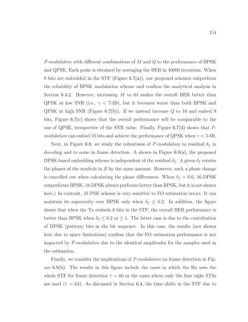
154
P-modulation with different combinations of M and Q to the performance of BPSK
and QPSK. Each point is obtained by averaging the BER in 40000 iterations. When
8 bits are embedded in the STF (Figure 6.7(a)), our proposed schemes outperform
the reliability of BPSK modulation scheme and confirm the analytical analysis in
Section 6.4.2. However, increasing M to 64 makes the overall BER better than
QPSK at low SNR (i.e., γ < 7 dB), but it becomes worse than both BPSK and
QPSK at high SNR (Figure 6.7(b)). If we instead increase Q to 16 and embed 9
bits, Figure 6.7(c) shows that the overall performance will be comparable to the
one of QPSK, irrespective of the SNR value. Finally, Figure 6.7(d) shows that P-
modulation can embed 10 bits and achieve the performance of QPSK when γ < 5 dB.
Next, in Figure 6.8, we study the robustness of P-modulation to residual δf in
decoding and to noise in frame detection. A shown in Figure 6.8(a), the proposed
DPSK-based embedding scheme is independent of the residual δf . A given δf rotates
the phases of the symbols in S by the same amount. However, such a phase change
is cancelled out when calculating the phase differences. When δf > 0.6, 16-DPSK
outperforms BPSK. (8-DPSK always performs better than BPSK, but it is not shown
here.) In contrast, M-PSK scheme is very sensitive to FO estimation errors. It can
maintain its superiority over BPSK only when δf ≤ 0.2. In addition, the figure
shows that when the Tx embeds 8 bits in the STF, the overall BER performance is
better than BPSK when δf ≤ 0.2 or ≥ 1. The latter case is due to the contribution
of DPSK (pattern) bits in the bit sequence. In this case, the results (not shown
here due to space limitations) confirm that the FO estimation performance is not
impacted by P-modulation due to the identical amplitudes for the samples used in
the estimation.
Finally, we consider the implications of P-modulation on frame detection in Fig-
ure 6.8(b). The results in this figure include the cases in which the Rx uses the
whole STF for frame detection τ = 80 or the cases where only the first eight STSs
are used (τ = 64). As discussed in Section 6.4, the time shifts in the STF due to

155
0 0.2 0.4 0.6 0.8 1 1.2δ
f (% of ∆
f)
10-4
10-3
10-2
10-1
BE
R
Pmod. (Q = 16)Pmod. (M = 32)Pmod. (Q = 8, M = 32)BPSK
(a) BER vs. residual δf
0 2 4 6 8 10 12γ (dB)
0
0.2
0.4
0.6
0.8
1
Prob
. Acc
urat
e Fr
ame
Det
ectio
n
BPSK, τ = 80, L = 4P-mod., τ = 80, L = 4P-mod., τ = 80, L = 6BPSK, τ = 64, L = 4P-mod., τ = 64, L = 4P-mod., τ = 64, L = 6
(b) Frame detection accuracy vs. γ (M = 32and Q = 16)
Figure 6.8: Robustness of P-modulation to channel impairments compared to BPSK(simulations).
using different patterns degrade the performance of STF-based frame detection. It
is mainly because the last two samples of the new STSs may have a high amplitude.
Hence, when the autocorrelation window is placed one or two samples before the
true start of the frame and the noise-only terms are multiplied by the last samples
of one of the STSs, Aτ may be very close to the Aτ at the true start. We verify it by
including two more time instances before the true frame start by setting (L = 6 vs.
L = 4). Figure 6.8(b) depicts that the accuracy of frame detection is comparable to
the one when the standard STF is used and L = 4. Therefore, if the Rx increments
its channel estimation length by two, it can account for the implications of P-mod-
ulation on frame detection. We also measured the FO estimation accuracy. The
results (not shown here due to space limitations) confirm that the FO estimation
performance is not impacted by P-modulation because the set of amplitudes of the
STF samples in P-modulation is the same as the default STF, though the order is
not the same.
Altogether, the results in Figure 6.8 suggest a trade-off between the number
of pattern bits (log2Q) and the number of rotation bits (log2M) depending on
the relative accuracy of the FO estimation to the frame detection. That is, when

156
the frame detection is good, the Tx can send more pattern bits and when the FO
estimation is accurate, the Tx can send more rotation bits.
6.7.2 USRP Experiments
We also implemented P-modulation on a USRP testbed that consists of two NI-
USRP 2922 devices, placed at a distance of 2m from each other. The Tx and
the Rx each use a 3-dBi antenna. The minimum transmission power of the Tx is
−8 dBm. However, because the transmission power is still very high with respect
to the environment’s noise (< −80 dBm), we first add artificial Gaussian noise to
the generated signal and then apply an artificial channel gain of −14 dB before the
transmission of the signal at the Tx. In the experiments, we vary the SNR at the Tx.
Furthermore, to separately study the impact of the channel and the FO estimation
errors in the experiments, we use an Ettus OctoClock-G clock distributer to provide
an external for the USRPs and eliminate the FO. Due to the robustness of FD-
DPSK to CSI and FO estimation errors, the Tx embeds 8 bits using Q = 16 and
M = 16. The signal is transmitted at 2.5GHz band to avoid external interference
in the environment. The Rx uses the channel estimation of L = 6 for the BPSK and
L = 8 for P-modulation. Frame detection lag parameter τ is set to its maximum.
Figure 6.9 shows the performance of P-modulation in USRP experiments when
The USRPs share a clock. Extending the channel estimation length by two samples
(λS/8 s) pays off and the frame detection accuracy of P-modulation statistically
matches with the one of the default STF, as shown in Figure 6.9 (a). With respect
to the BER performance, we observe in Figure 6.9 (b) that CSI estimation errors
contribute to high BER of phase rotation bits even though M is set to 16. (Each
point is obtained by averaging the BER in 5000 transmissions.) However, the pattern
bits modulated using 16-DPSK are very robust to such errors, even more than BPSK.
The low BER of the pattern bits makes the overall BER of the 8-bit P-modulation
and BPSK comparable.
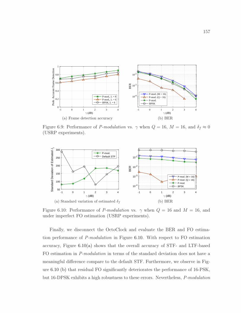
157
-1 0 1 2 3 4γ (dB)
0
0.2
0.4
0.6
0.8
1
Prob
. Acc
urat
e Fr
ame
Det
ectio
n
P-mod., L = 8P-mod., L = 6BPSK, L = 6
(a) Frame detection accuracy
-1 0 1 2 3 4γ (dB)
10-4
10-3
10-2
BE
R
P-mod. (M = 16)P-mod. (Q = 16)P-mod.BPSK
(b) BER
Figure 6.9: Performance of P-modulation vs. γ when Q = 16, M = 16, and δf ≈ 0(USRP experiments).
-1 0 1 2 3 4
γ (dB)
50
100
150
200
250
300
Sta
ndar
d D
evia
tion
of E
stim
ated
δf
P-mod.Default STF
(a) Standard variation of estimated δf
-1 0 1 2 3 4
γ (dB)
10-4
10-3
10-2
10-1
BE
R
P-mod. (M = 16)P-mod. (Q = 16)P-mod.BPSK
(b) BER
Figure 6.10: Performance of P-modulation vs. γ when Q = 16 and M = 16, andunder imperfect FO estimation (USRP experiments).
Finally, we disconnect the OctoClock and evaluate the BER and FO estima-
tion performance of P-modulation in Figure 6.10. With respect to FO estimation
accuracy, Figure 6.10(a) shows that the overall accuracy of STF- and LTF-based
FO estimation in P-modulation in terms of the standard deviation does not have a
meaningful difference compare to the default STF. Furthermore, we observe in Fig-
ure 6.10 (b) that residual FO significantly deteriorates the performance of 16-PSK,
but 16-DPSK exhibits a high robustness to these errors. Nevertheless, P-modulation
158
in this case has a much lower BER than BPSK.
6.8 Summary
In this chapter, we considered the STF of the preamble in the PHY layer of the IEEE
OFDM systems to modulate user-information bits in order to enhance the security
in the PHY layer, improve the throughput, or provide a PHY-layer signalling for
new applications. To do so, we proposed P-modulation in which a set of new STF
waveforms are constructed that comply with the requirements of the preamble of the
OFDM-based IEEE WLAN systems. These new waveforms are obtained using two
techniques: shift in the time domain and phase rotation in the frequency domain. We
then modulated a bit sequence using these two techniques. When the robustness of
BPSK modulation scheme is expected, our analysis indicates that when operating
on 20 MHz bandwidth, the transmitter can embed up to 8 bits and improve the
frame utilization using P-modulation. If the a higher bandwidth is used, higher
capacity can be achieved. Our simulation and USRP experiment results confirm
that practicality of P-modulation in real scenarios.
159
CHAPTER 7
CONCLUSIONS AND FUTURE RESEARCH
DIRECTIONS
7.1 Conclusions
In this dissertation, we considered the leakage of various transmission attributes in
encrypted wireless communications and developed methods for hiding or obfuscating
these attributes. In particular, we focused on the frame preamble and (1) revealed
the vulnerability of preamble-based FO estimation mechanism in OFDM systems
to stealth jamming attacks, and (2) exploited the preamble to embed information
bits (e.g., transmitter identifier) and facilitate PHY-layer encryption. We also used
friendly jamming signal as a random noise signal for securing communications in
multi-link/path scenarios against eavesdropping, or as an modulated signal for en-
crypting PHY frames and obfuscating modulation schemes. Our main achievements
and finding are summarized as follows.
First, we designed and experimentally demonstrated a highly disruptive but
efficient-efficient DoS attack against OFDM systems. This attack succeeds even
when the PHY frame is shielded by interleaving and channel coding. The attack fo-
cuses on the FO estimation process, and is channel-independent and robust to time-
synchronization errors at Eve through applying the proposed pairing and chaining
rules. The attack lasts for less than the duration of an OFDM symbol, i.e., less than
1% of a typical frame duration, and is at least 30% more efficient than previously
reported attacks. Though short-lived, the attack results in a shift in subcarrier in-
dices and the maximum possible BER (50%) even when the jamming signal at Bob

160
is ∼ 1.4 times weaker than Alice’s signal. The simulation results show that different
modulation schemes are equally susceptible if the FO attack can shift the subcarrier
indices, and higher modulation orders are more affected when the attack impacts
only the channel estimation. We also sketched four possible mitigation approaches.
Second, by jointly optimizing the powers and locations of the friendly jamming
nodes deployed in small-scale multi-link wireless networks, we minimized the total
jamming power required to secure legitimate transmissions in the presence of eaves-
droppers. We then proposed two optimization strategies: per-link and network-
wide (all links jointly). It was shown that our per-link scheme outperforms previ-
ous schemes in terms of energy efficiency (55–99 percent power saving). Moreover,
the network-wide optimization was shown to be more energy-efficient than per-link
scheme (14–38 percent additional power saving) and also requires about half the
number of friendly jamming nodes than per-link optimization. For multihop sce-
narios, we proposed a routing metric that finds a secure path that requires minimal
jamming power.
Third, we proposed Friendly CryptoJam (FCJ), a combination of friendly jam-
ming and low-level encryption, to effectively protect the confidentiality of lower-
layer fields and prevent SCI-based traffic classification, rate-adaptation, plaintext,
dictionary, modulation detection, and device-based tracking attacks. FCJ employs
three main techniques. (1) modulation-aware encryption is used to perfectly se-
cure plaintext headers and readily encrypted payload, (2) an energy-efficient and
indistinguishable modulation unification technique based on trellis-coded modula-
tion (TCM) is used to obfuscate the payload’s modulation scheme and partially
decorrelate the modulated-frame duration from the payload size, and (3) a mes-
sage embedding technique is applied to overlay a frame-specific PHY-layer sender
identifier on the frame preamble, obviating the need for MAC address and facilitat-
ing session-key lookup at PHY layer. We showed theoretically and experimentally
that such an identifier that is constructed using a series of shifted Barker sequences

161
and is superposed it on the 802.11b preamble can be reliably detected at the re-
ceiver without considerably affecting typical preamble functions. The simulation
and experimental results also verify that modulation unification and encryption are
successful in hiding the true packet size, modulation scheme, and frame content
without degrading the BER performance.
Fourth, we considered the STF of the preamble in the PHY layer of the IEEE
OFDM systems to carry information bits in order to improve the throughput, iden-
tify the transmitter in the PHY-layer and facilitate PHY header encryption, or
mitigate the FO attack by varying the preamble. To do so, we constructed a set of
new preamble waveforms that comply with the requirements of the preamble of the
OFDM systems in IEEE WLAN systems. These new waveforms are obtained using
two techniques: shift in the time domain and phase rotation in the frequency domain.
Our analysis indicates that in the systems that operate on 20 MHz bandwidth, the
transmitter can embed up to 8 bits, and facilitate several security measures (e.g.,
full-frame encryption). If the a higher bandwidth is used, higher speed also can
be achieved. Our simulation and USRP experiment results showed that the pro-
posed scheme can maintain the performance of BPSK modulation scheme and also
is robust to channel variations and frame detection errors.
7.2 Future Research Directions
We envision several future directions based on the schemes developed and the
achieved results in this dissertation.
First, in this dissertation we assumed a single Tx-Rx-pair and presents a jamming
attack against FO estimation in OFDM systems. In the case of multiple Tx-Rx pairs,
Eve can construct a database of the FOs between different Tx-Rx pairs. Benefiting
from CSMA/CA channel access mechanism, Eve can consider one transmission at
a time and then leverage protocol semantics (e.g., data-ACK exchanges) to guess
the Tx and Rx of an upcoming transmission. Extension of this attack to multi-link
162
scenarios and further investigation of this issue can be considered for future work.
Second, this dissertation only sketches four countermeasures against the pro-
posed FO attack. Detailed analysis and evaluation of these countermeasures are the
next steps for shielding OFDM systems against FO attacks.
Third, in this dissertation, the friendly jamming devices are assumed to be single-
antenna and dedicated to friendly jamming. To extend this work, one can assume
these devices as both relay nodes and friendly jamming devices, and optimize their
placements to minimize the jamming power while achieving certain quality of service.
Using MIMO devices can be a choice when combining the role of relaying with
the role of jamming. Furthermore, distributed MIMO devices can be exploited to
increase the channel diversity and reduce the vulnerability zone around the receiver
due to the strong line-of-sight.
Fourth, FCJ in this dissertation is designed for single-antenna devices. Extension
of FCJ for MIMO devices and multi-user MIMO scenarios is a timely direction for
future.
Finally, the scenarios considered in this dissertation mainly focus on WLAN sys-
tems. However, by the emerge of 5G and upcoming standards such as 802.11ax,
various other applications will become pervasive. Vehicle-to-vehicle Vehicle-to-
pedestrian communications are among these applications. Considering privacy in
these applications and their specific features (e.g., fast changing the base station),
we will need customized privacy-preserving schemes in the future.
163
REFERENCES
[1] “IEEE Std 802.11a-1999,” Supplement to IEEE Standard for Informa-tion Technology— Telecommunications and Information Exchange BetweenSystems—Local and Metropolitan Area Networks—Specific Requirements: Part11: Wireless LAN Medium Access Control (MAC) and Physical Layer (PHY)Specifications: High-Speed Physical Layer in the 5 GHz Band, 1999.
[2] “Gartner Says Worldwide Traditional PC, Tablet, Ultramobile and MobilePhone Shipments to Grow 4.2 Percent in 2014,” 2014. [Online]. Available:http://www.gartner.com/newsroom/id/2791017
[3] G. Wilkinson, “Black Hat Asia 2014 - the machines that betrayed theirmasters,” 2014. [Online]. Available: https://www.youtube.com/watch?v=NiiIoZ7y64
[4] R. Savage, “Snooping garbage bins in city of London ordered to be disabled,”Aug. 2013. [Online]. Available: http://goo.gl/omktFa
[5] “IEEE 802 EC privacy recommendation study group,” Jul. 2014. [Online].Available: http://www.ieee802.org/PrivRecsg/
[6] F. Armknecht, J. Girao, A. Matos, and R. L. Aguiar, “Who said that? privacyat link layer,” in IEEE INFOCOM’07 conf., Anchorage, Alaska, USA, May2007, pp. 2521–2525.
[7] B. Greenstein, D. McCoy, J. Pang, T. Kohno, S. Seshan, and D. Wetherall,“Improving wireless privacy with an identifier-free link layer protocol,” in Proc.6th Int. Conf. Mobile Syst., Appl., and Services, Breckenridge, CO, USA, 2008,pp. 40–53.
[8] Y. Fan, B. Lin, Y. Jiang, and X. Shen, “An efficient privacy-preserving schemefor wireless link layer security,” in Proc. IEEE GLOBECOM conf., New Or-leans, LO, USA, Nov. 2008, pp. 1–5.
[9] M. Alleven, “IEEE study group recommends improvements in Wi-Fi security,”Jul. 2015. [Online]. Available: http://goo.gl/BPXMyg

164
[10] T. Stober, M. Frank, J. Schmitt, and I. Martinovic, “Who do you sync youare?: Smartphone fingerprinting via application behaviour,” in Proc. SixthACM Conf. Security and Privacy in Wireless and Mobile Networks (WiSec’13),Budapest, Hungary, 2013, pp. 7–12.
[11] C. Neumann, O. Heen, and S. Onno, “An empirical study of passive 802.11device fingerprinting,” in 32nd IEEE Int. Conf. Distributed Computing Syst.Workshops (ICDCSW’12), Jun. 2012, pp. 593–602.
[12] Q. Wang, A. Yahyavi, B. Kemme, and W. He, “I know what you did on yoursmartphone: Inferring app usage over encrypted data traffic,” in Proc. IEEEConf. Commun. and Network Security CNS’15, Sept 2015, pp. 433–441.
[13] V. Brik, S. Banerjee, M. Gruteser, and S. Oh, “Wireless device identificationwith radiometric signatures,” in Proc. 14th ACM Int. Conf. Mobile Computingand Networking (MobiCom’08), San Francisco, California, USA, 2008, pp. 116–127.
[14] B. Miller, L. Huang, A. Joseph, and J. Tygar, “I know why you went to theclinic: Risks and realization of HTTPS traffic analysis,” Privacy EnhancingTechnologies, vol. 8555, pp. 143–163, 2014.
[15] K. Dyer, S. Coull, T. Ristenpart, and T. Shrimpton, “Peek-a-boo, I still seeyou: Why efficient traffic analysis countermeasures fail,” in Proc. IEEE Symp.Security and Privacy (SP’12), May 2012, pp. 332–346.
[16] F. Zhang, W. He, X. Liu, and P. G. Bridges, “Inferring users’ online activitiesthrough traffic analysis,” in Proc. 4th ACM Conf. Wireless Network Security(WiSec’11), Hamburg, Germany, 2011, pp. 59–70.
[17] S. Dai, A. Tongaonkar, X. Wang, A. Nucci, and D. Song, “Networkprofiler: To-wards automatic fingerprinting of android apps,” in Proc. IEEE INFOCOM’13,Apr. 2013, pp. 809–817.
[18] S. Chen, R. Wang, X. Wang, and K. Zhang, “Side-channel leaks in web appli-cations: A reality today, a challenge tomorrow,” in Proc. IEEE Symp. Securityand Privacy (SP’10), May 2010, pp. 191–206.
[19] G. Noubir, R. Rajaraman, B. Sheng, and B. Thapa, “On the robustness ofIEEE 802.11 rate adaptation algorithms against smart jamming,” in Proc. 4thACM Conf. Wireless Network Security (WiSec’11), Hamburg, Germany, Jun.2011, pp. 97–108.
165
[20] M. J. LaPan, T. C. Clancy, and R. W. McGwier, “Physical layer orthogonalfrequency-division multiplexing acquisition and timing synchronization secu-rity,” Wireless Commun. and Mobile Computing, vol. 16, no. 2, pp. 177–191,Feb. 2016.
[21] ——, “Phase warping and differential scrambling attacks against OFDM fre-quency synchronization,” in Proc. IEEE Int. Conf. Acoust., Speech, Signal Pro-cess. (ICASSP’13), Vancouver, BC, Canada, May 2013, pp. 2886–2890.
[22] C. Shahriar, S. Sodagari, R. McGwier, and T. Clancy, “Performance impactof asynchronous off-tone jamming attacks against OFDM,” in Proc. IEEE Int.Conf. Commun. (ICC’13), Budapest, Hungary, Jun. 2013, pp. 2177–2182.
[23] S. Goel and R. Negi, “Guaranteeing secrecy using artificial noise,” IEEE Trans.on Wireless Commun., vol. 7, no. 6, pp. 2180–2189, Jun. 2008.
[24] “IEEE Std 802.11n-2009,” IEEE Standard for Information Technology—Telecommunications and Information Exchange Between Systems—Local andMetropolitan Area Networks—Specific Requirements: Part 11: Wireless LANMedium Access Control (MAC) and Physical Layer (PHY) SpecificationsAmendment 5: Enhancements for Higher Throughput, 2009.
[25] T. M. Schmidl and D. C. Cox, “Robust frequency and timing synchronizationfor OFDM,” IEEE Trans. Communications, vol. 45, no. 12, pp. 1613–1621,1997.
[26] J. Heiskala and J. Terry, OFDM Wireless LANs: A Theoretical and PracticalGuide. SAMS Publishing Indianapolis, 2002.
[27] L. Weng, R. Murch, and V. Lau, “SISO-OFDM channel estimation in thepresence of carrier frequency offset,” in Proc. IEEE Wireless Commun. andNetw. Conf. (WCNC’06), vol. 3, Las Vegas, NV, USA, Apr. 2006, pp. 1444–1449.
[28] Y. Zhang, “Method, apparatus and system for carrier frequency offset estima-tion,” Oct. 2013, US Patent App. 13/597,204.
[29] G. Lin and G. Noubir, “On link layer denial of service in data wireless LANs,”Wireless Communications and Mobile Computing, vol. 5, no. 3, pp. 273–284,2005.

166
[30] K. Pelechrinis, M. Iliofotou, and S. Krishnamurthy, “Denial of service attacksin wireless networks: The case of jammers,” Commun. Surveys Tuts., vol. 13,no. 2, pp. 245–257, 2011.
[31] M. Strasser, B. Danev, and S. Capkun, “Detection of reactive jamming in sensornetworks,” ACM Trans. Sensor Networks, vol. 7, no. 2, pp. 16:1–16:29, Aug.2010.
[32] T. C. Clancy, “Efficient OFDM denial: Pilot jamming and pilot nulling,” inProc. IEEE Int. Conf. Commun. (ICC’11), Kyoto, Japan, Jun. 2011.
[33] R. Gummadi, D. Wetherall, B. Greenstein, and S. Seshan, “Understanding andmitigating the impact of RF interference on 802.11 networks,” in Proc. ACMSIGCOMM’07 Conf., Kyoto, Japan, 2007, pp. 385–396.
[34] C. Mueller-Smith and W. Trappe, “Efficient OFDM denial in the absence ofchannel information,” in Proc. Military Commun. Conf. (MILCOM’13), SanDiego, CA, USA, Nov. 2013, pp. 89–94.
[35] L. Sanguinetti, M. Morelli, and H. Poor, “Frame detection and timing ac-quisition for OFDM transmissions with unknown interference,” IEEE Trans.Wireless Commun., vol. 9, no. 3, pp. 1226–1236, Mar. 2010.
[36] H. Rahbari, M. Krunz, and L. Lazos, “Security vulnerability and countermea-sures of frequency offset correction in 802.11a systems,” in Proc. IEEE INFO-COM’14, Toronto, ON, Canada, Apr. 2014, pp. 1015–1023.
[37] T. Pollet, M. Van Bladel, and M. Moeneclaey, “BER sensitivity of OFDM sys-tems to carrier frequency offset and Wiener phase noise,” IEEE Trans. Com-mun., vol. 43, no. 234, pp. 191–193, 1995.
[38] H. Rahul, H. Hassanieh, and D. Katabi, “SourceSync: a distributed wirelessarchitecture for exploiting sender diversity,” in Proc. ACM SIGCOMM, NewDelhi, India, Sep. 2010, pp. 171–182.
[39] H. Rahbari, M. Krunz, and L. Lazos, “Jamming attack on frequencyoffset estimation in OFDM systems,” University of Arizona, Departmentof ECE, Tech. Rep. TR-UA-ECE-2015-1, Jun. 2015. [Online]. Available:http://goo.gl/pAxxaR
[40] D. Nguyen, C. Sahin, B. Shishkin, N. Kandasamy, and K. R. Dandekar, “Areal-time and protocol-aware reactive jamming framework built on software-defined radios,” in Proc. 2014 ACM Workshop Software Radio ImplementationForum, Chicago, Illinois, USA, 2014, pp. 15–22.

167
[41] N. Sufyan, N. Saqib, and M. Zia, “Detection of jamming attacks in 802.11bwireless networks,” EURASIP J. Wireless Commun. and Networking, vol. 2013,2013.
[42] J. Luo, J. Andrian, and C. Zhou, “Bit error rate analysis of jamming for OFDMsystems,” in Wireless Telecommun. Symp. (WTS’07), Apr. 2007, pp. 1–8.
[43] C. Shahriar et al., “PHY-Layer resiliency in OFDM communications: A tuto-rial,” IEEE Commun. Surveys Tuts., vol. 17, no. 1, pp. 292–314, 2015.
[44] A. Wyner, “The wire-tap channel,” The Bell System Technical Journal, vol. 54,no. 8, pp. 1355–1387, Oct. 1975.
[45] I. Csiszar and J. Korner, “Broadcast channels with confidential messages,”IEEE Trans. Inf. Theory, vol. 24, no. 3, pp. 339–348, May 1978.
[46] J. Zhang, L. Fu, and X. Wang, “Asymptotic analysis on secrecy capacity inlarge-scale wireless networks,” IEEE/ACM Trans. Networking, vol. 22, no. 1,pp. 66–79, Feb. 2014.
[47] O. Koyluoglu, C. Koksal, and H. Gamal, “On secrecy capacity scaling in wire-less networks,” IEEE Trans. Inf. Theory, vol. 58, no. 5, pp. 3000–3015, May2012.
[48] A. Sheikholeslami, D. Goeckel, H. Pishro-Nik, and D. Towsley, “Physical layersecurity from inter-session interference in large wireless networks,” in Proc.IEEE INFOCOM, Orlando, FL, USA, Mar. 2012, pp. 1179–1187.
[49] M. Ghaderi, D. Goeckel, A. Orda, and M. Dehghan, “Efficient wireless securitythrough jamming, coding and routing,” in Proc. 10th IEEE Int. Conf. Sensing,Commun., Netw. (SECON), New Orleans, USA, Jun. 2013, pp. 505–513.
[50] ——, “Minimum energy routing and jamming to thwart wireless network eaves-droppers,” IEEE Trans. Mobile Comput., vol. 14, no. 7, pp. 1433–1448, Jul.2015.
[51] D. Goeckel, S. Vasudevan, D. Towsley, S. Adams, Z. Ding, and K. Leung,“Artificial noise generation from cooperative relays for everlasting secrecy intwo-hop wireless networks,” IEEE J. Sel. Areas Commun., vol. 29, no. 10, pp.2067–2076, Dec. 2011.
[52] M. Chiang, C. W. Tan, D. Palomar, D. O’Neill, and D. Julian, “Power controlby geometric programming,” IEEE Trans. Wireless Commun., vol. 6, no. 7, pp.2640–2651, Jul. 2007.
168
[53] T. Shu and M. Krunz, “Coverage-time optimization for clustered wireless sensornetworks: A power-balancing approach,” IEEE/ACM Trans. on Netw., vol. 18,no. 1, pp. 202–215, Feb. 2010.
[54] C. Beightler and D. Phillips, Applied Geometric Programming. Wiley, 1976.
[55] C. Cardoso, A. Castro, and A. Klautau, “An efficient FPGA IP core for auto-matic modulation classification,” IEEE Embedded Syst. Lett., vol. 5, no. 3, pp.42–45, Sep. 2013.
[56] J. Freudiger, “How talkative is your mobile device?: an experimental studyof Wi-Fi probe requests,” in Proc. 8th ACM Conf. Security and Privacy inWireless & Mobile Networks (WiSec’15), New York City, USA, Jun. 2015.
[57] S. U. Rehman, K. W. Sowerby, and C. Coghill, “Analysis of impersonationattacks on systems using RF fingerprinting and low-end receivers,” J. Comput.and Syst. Sci., vol. 80, no. 3, pp. 591–601, 2014, special Issue on WirelessNetwork Intrusion.
[58] T. D. Vo-Huu and G. Noubir, “Mitigating rate attacks through crypto-codedmodulation,” in Proc. 16th ACM Int. Symp. Mobile Ad Hoc Networking andComputing (MobiHoc’15), Hangzhou, China, 2015, pp. 237–246.
[59] H. Rahbari and M. Krunz, “Friendly CryptoJam: A mechanism for securingphysical-layer attributes,” in Proc. 7th ACM Conf. Security and Privacy inWireless & Mobile Networks (WiSec’14), Oxford, United Kingdom, Jul. 2014,pp. 129–140.
[60] F. Zhang, W. He, Y. Chen, Z. Li, X. Wang, S. Chen, and X. Liu, “Thwart-ing Wi-Fi side-channel analysis through traffic demultiplexing,” IEEE Trans.Wireless Commun., vol. 13, no. 1, pp. 86–98, Jan. 2014.
[61] N. Kolokotronis, A. Katsiotis, and N. Kalouptsidis, “Short paper: attackingand defending lightweight PHY security schemes for wireless communications,”in Proc. 7th ACM Conf. Security and Privacy in Wireless & Mobile Networks(WiSec’14), Oxford, United Kingdom, Jul. 2014, pp. 177–182.
[62] A. Katsiotis, N. Kolokotronis, and N. Kalouptsidis, “Physical layer security viasecret trellis pruning,” in Proc. IEEE Int. Symp. Personal Indoor and MobileRadio Commun. (PIMRC’13), Sep. 2013, pp. 507–512.
[63] ——, “Secure encoder designs based on turbo codes,” in Proc. IEEE ICC’15,London, UK, Jun. 2015, pp. 4315–4320.

169
[64] N. Anand, S.-J. Lee, and E. Knightly, “STROBE: Actively securing wire-less communications using zero-forcing beamforming,” in Proc. IEEE INFO-COM’12, Mar. 2012, pp. 720–728.
[65] S. Goel and R. Negi, “Guaranteeing secrecy using artificial noise,” IEEE Trans.Wireless Commun., vol. 7, no. 6, pp. 2180–2189, Jun. 2008.
[66] S. Gollakota, H. Hassanieh, B. Ransford, D. Katabi, and K. Fu, “They canhear your heartbeats: Non-invasive security for implantable medical devices,”in Proc. ACM SIGCOMM’11, Toronto, Ontario, Canada, Aug. 2011, pp. 2–13.
[67] N. Tippenhauer, L. Malisa, A. Ranganathan, and S. Capkun, “On limitations offriendly jamming for confidentiality,” in Proc. IEEE symp. Security and Privacy(SP ’13), May 2013, pp. 160–173.
[68] M. Schulz, A. Loch, and M. Hollick, “Practical known-plaintext attacks againstphysical layer security in wireless MIMO systems,” in Proc. Network and Dis-tributed Syst. Security Symp. (NDSS’14), San Diego, CA, USA, Feb. 2014.
[69] X. He, H. Dai, W. Shen, and P. Ning, “Is link signature dependable for wirelesssecurity?” in Proc. IEEE INFOCOM’13, Apr. 2013, pp. 200–204.
[70] S. Gollakota and D. Katabi, “ZigZag decoding: Combating hidden terminalsin wireless networks,” in Proc. ACM SIGCOMM’08, Seattle, WA, USA, Oct.2008, pp. 159–170.
[71] F. Hameed, O. Dobre, and D. Popescu, “On the likelihood-based approach tomodulation classification,” IEEE Trans. Wireless Commun., vol. 8, no. 12, pp.5884–5892, Dec. 2009.
[72] S. Ravanbakhsh, C. Srinivasa, B. Frey, and R. Greiner, “Min-max problems onfactor graphs,” in Proc. 31st Int. Conf. Machine Learning (ICML’14), Beijing,China, Jun. 2014, pp. 1035–1043.
[73] G. Ungerboeck, “Channel coding with multilevel/phase signals,” IEEE Trans.Information Theory, vol. 28, no. 1, pp. 55–67, 1982.
[74] E. Biglieri, D. Divsalar, M. K. Simon, and P. J. McLane, Introduction to Trellis-Coded Modulation with Applications, 1st ed., J. Griffin, Ed. Upper SaddleRiver, NJ, USA: Prentice-Hall, Inc., 1991.
[75] G. Bertoni, J. Daemen, M. Peeters, and G. Van Assche, “Sponge-based pseudo-random number generators,” Cryptographic Hardware and Embedded Systems(CHES), vol. 6225, pp. 33–47, 2010.

170
[76] I. Dinur, P. Morawiecki, J. Pieprzyk, M. Srebrny, and M. Straus, “Cube at-tacks and cube-attack-like cryptanalysis on the round-reduced Keccak spongefunction,” Advances in Cryptology–EUROCRYPT, pp. 733–761, 2015.
[77] Y. Fan, B. Lin, Y. Jiang, and X. Shen, “An efficient privacy-preserving schemefor wireless link layer security,” in Proc. IEEE Int. Global Telecommun. Conf.(GLOBECOM’08), New Orleans, LA, USA, Nov. 2008.
[78] O. Bejarano, S. Quadri, O. Gurewitz, and E. Knightly, “Scaling multi-userMIMO WLAN: the case of concurrent uplink control messages,” in Proc. IEEESECON’15, Seattle, WA, USA, Jun. 2015.
[79] “IEEE Std 802.11ac-2013,” IEEE Standard for Information technology–Telecommunications and information exchange between systems—Local andmetropolitan area networks—Specific requirements–Part 11: Wireless LANMedium Access Control (MAC) and Physical Layer (PHY) Specifications–Amendment 4: Enhancements for Very High Throughput for Operation inBands below 6 GHz, 2013.
[80] N. Anand, S.-J. Lee, and E. Knightly, “STROBE: Actively securing wire-less communications using Zero-Forcing Beamforming,” in Proc. IEEE INFO-COM’12, Orlando, FL, USA, Mar. 2012, pp. 720–728.
[81] Z. Feng, J. Ning, I. Broustis, K. Pelechrinis, S. Krishnamurthy, and M. Falout-sos, “Coping with packet replay attacks in wireless networks,” in Proc. IEEESECON’11 conf., Jun. 2011, pp. 368–376.
[82] T. C. Clancy, “Efficient OFDM denial: Pilot jamming and pilot nulling,” inProc. IEEE Int. Conf. Commun. (ICC’11), 2011, pp. 1–5.
[83] C. Shahriar, R. McGwier, and T. Clancy, “Performance impact of pilot tonerandomization to mitigate OFDM jamming attacks,” in IEEE Consumer Com-mun. Networking Conf. (CCNC’13), Jan. 2013, pp. 813–816.
[84] Q. Wang, A. Yahyavi, B. Kemme, and W. He, “I know what you did on yoursmartphone: Inferring app usage over encrypted data traffic,” in Proc. IEEEConf. Commun. Network Security (CNS’15), Sep. 2015, pp. 433–441.
[85] C. J. Bernardos, J. C. Zuniga, and P. O’Hanlon, “Wi-Fi Internet connectivityand privacy: hiding your tracks on the wireless Internet,” in Proc. IEEE Conf.Standards for Commun. Netw. (CSCB’15), Tokyo, Japan, Oct. 2015.

171
[86] M. Gruteser and D. Grunwald, “Enhancing location privacy in wireless LANthrough disposable interface identifiers: a quantitative analysis,” Mobile Net-works and Applications, vol. 10, no. 3, pp. 315–325, 2005.
[87] “Specification framework for TGah,” May 2013, doc.: IEEE P802.11-11/1137r15.
[88] R. Boehnke and T. Doelle, “Alternative proposal for BRAN SYNCHpreamble,” Mar. 1999, doc.: IEEE 802.11-99/048. [Online]. Available:http://goo.gl/NIy6BM
[89] “P802.11a draft D5.5 comments,” Jun. 1999, doc.: IEEE P802.11-99/1460.[Online]. Available: http://goo.gl/Rw3Zxi
[90] A. V. Oppenheim, A. S. Willsky, and S. H. Nawab, Signals & Systems.Prentice-Hall, 1996.
[91] K. Zhong, T. T. Tjhung, and F. Adachi, “A general SER formula for an OFDMsystem with MDPSK in frequency domain over Rayleigh fading channels,”IEEE Trans. Commun., vol. 52, no. 4, pp. 584–594, 2004.
[92] M. K. Simon and M.-S. Alouini, Digital communication over fading channels.John Wiley & Sons, 2005, vol. 95.
[93] K. Sathananthan and C. Tellambura, “Probability of error calculation of OFDMsystems with frequency offset,” EEE Trans. Commun., vol. 49, no. 11, pp. 1884–1888, Nov. 2001.