ø 1cdn1.blocksassets.com/assets/ozito/ozito-product... · important that you read and follow the...
TRANSCRIPT


Motor: 300WInput: 220-240V ~ 50HzViscosity: 20 to 80 seconds (DIN-S)Max Liquid Flow: 450 ml/minPot Capacity: 800mlNozzle: ø2.5mmWeight (tool only): 1.5kgs
1. Air Cap2. Nozzle3. Quick release dial4. Air filter
5. Soft grip handle6. Spray regulator dial7. Paint pot8. Trigger
2
1
SPECIFICATIONS - MODEL NO. SGP-300
1
KNOW YOUR PRODUCT
6
7
8
3
4
5

2
TABLE OF CONTENTS
SPECIFICATIONS ………………………………………..
INTRODUCTION…………………………………………
ELECTRICAL SAFETY…………….………………………
GENERAL POWER TOOL SAFETY WARNINGS………
ADDITIONAL SAFETY INSTRUCTIONS FOR SPRAY GUNS ……………………………………………
ASSEMBLY…………………………………………………
OPERATION………………………………………………
MAINTENANCE…………….……………………………
TROUBLE SHOOTING….………………………………
SPARE PARTS …………….……………………………...
DESCRIPTION OF SYMBOLS ………………………….
PACK CONTENTS ………………………………………
WARRANTY………………………………………………
Page 1
Page 3
Page 3
Page 4
Page 6
Page 7
Page 9
Page 14
Page 15
Page 16
Page 16
Page 17
Page 18
INTRODUCTION
3
ELECTRICAL SAFETY
Congratulations on purchasing an Ozito Spray Gun. We aim toprovide quality tools at an affordable price. We hope you willenjoy using this tool for many years. Before using, it is mostimportant that you read and follow the instructions in this manual,even if you feel you are quite familiar with this type of product.
Your Spray Gun SGP-300 has been designed for Spray Paintingsmall to medium tasks around the home. Objects such as toys,household and garden furniture, trellis, models etc. and isintended for DIY use only.
WARNING! When using mains-powered equipment, basic safetyprecautions, including the following, should always be followed to reducerisk of fire, electric shock, personal injury and material damage.
Read and understand the manual prior to operating this tool.
Save these instructions and other documents supplied with this tool for future reference.
The electric motor has been designed for 230V and 240V only. Always check thatthe power supply corresponds to the voltage on the rating plate.
Note: The supply of 230V and 240V on Ozito tools are interchangeable for Australia and New Zealand.
This tool is double insulated in accordance with AS/NZS60745.1; therefore no earth wire is required.
If the supply cord is damaged, it must be replaced by a qualified electrician or apower tool repairer in order to avoid a hazard.
If operating a power tool in a damp location is unavoidable use a residual currentdevice (RCD) protected supply Use of an RCD reduces the risk of electric shock.
Note: Double insulation does not take the place of normal safety precautions whenoperating this tool. The insulation system is for added protection against injuryresulting from a possible electrical insulation failure within the tool.
Using an Extension Lead
Always use an approved extension lead suitable for the power input of this tool.Before use, inspect the extension lead for signs of damage, wear and ageing.Replace the extension lead if damaged or defective. When using an extension leadon a reel, always unwind the lead completely. Use of an extension lead not suitablefor the power input of the tool or which is damaged or defective may result in arisk of fire and electric shock.
!!
!!

4
GENERAL POWER TOOL SAFETY WARNINGS
WARNING! Read all safety warnings and all instructions. Failure to follow the warnings and instructions may result in electric shock, fire and/orserious injury.
Save all warnings and instructions for future reference.The term “power tool" in all of the warnings refers to your mains-operated(corded) power tool or battery-operated (cordless) power tool.
1) Work area safety
a) Keep work area clean and well lit. Cluttered or dark areas invite accidents.
b) Do not operate power tools in explosive atmospheres, such as in thepresence of flammable liquids, gases or dust. Power tools create sparks whichmay ignite the dust or fumes.
c) Keep children and bystanders away while operating a power tool. Distractionscan cause you to lose control.
2) Electrical safety
a) Power tool plugs must match the outlet. Never modify the plug in any way.Do not use any adapter plugs with earthed (grounded) power tools.Unmodified plugs and matching outlets will reduce risk of electric shock.
b) Avoid body contact with earthed or grounded surfaces, such as pipes,radiators, ranges and refrigerators. There is an increased risk of electric shock ifyour body is earthed or grounded.
c) Do not expose power tools to rain or wet conditions. Water entering a powertool will increase the risk of electric shock.
d) Do not abuse the cord. Never use the cord for carrying, pulling or unpluggingthe power tool. Keep cord away from heat, oil, sharp edges or moving parts.Damaged or entangled cords increase the risk of electric shock.
e) When operating a power tool outdoors, use an extension cord suitable foroutdoor use. Use of a cord suitable for outdoor use reduces the risk of electric shock.
f) If operating a power tool in a damp location is unavoidable, use a residualcurrent device (RCD) protected supply. Use of an RCD reduces the risk ofelectric shock.
3) Personal safety
a) Stay alert, watch what you are doing and use common sense when operatinga power tool. Do not use a power tool while you are tired or under theinfluence of drugs, alcohol or medication. A moment of inattention whileoperating power tools may result in serious personal injury.
b) Use personal protective equipment. Always wear eye protection. Protectiveequipment such as dust mask, non-skid safety shoes, hard hat, or hearingprotection used for appropriate conditions will reduce personal injuries.
c) Prevent unintentional starting. Ensure the switch is in the off-position beforeconnecting to power source and/or battery pack, picking up or carrying thetool. Carrying power tools with your finger on the switch or energising power toolsthat have the switch on invites accidents.
!!
!!

5
GENERAL POWER TOOL SAFETY WARNINGS (cont.)
d) Remove any adjusting key or wrench before turning the power tool on. Awrench or a key left attached to a rotating part of the power tool may result inpersonal injury.
e) Do not overreach. Keep proper footing and balance at all times. Thisenables better control of the power tool in unexpected situations.
f) Dress properly. Do not wear loose clothing or jewellery. Keep your hair,clothing and gloves away from moving parts. Loose clothes, jewellery orlong hair can be caught in moving parts.
g) If devices are provided for the connection of dust extraction and collectionfacilities, ensure these are connected and properly used. Use of dustcollection can reduce dust-related hazards.
4) Power tool use and care
a) Do not force the power tool. Use the correct power tool for yourapplication. The correct power tool will do the job better and safer at the ratefor which it was designed.
b) Do not use the power tool if the switch does not turn it on and off. Anypower tool that cannot be controlled with the switch is dangerous and must be repaired.
c) Disconnect the plug from the power source and/or the battery pack fromthe power tool before making any adjustments, changing accessories, orstoring power tools. Such preventive safety measures reduce the risk ofstarting the power tool accidentally.
d) Store idle power tools out of the reach of children and do not allowpersons unfamiliar with the power tool or these instructions to operatethe power tool. Power tools are dangerous in the hands of untrained users.
e) Maintain power tools. Check for misalignment or binding of moving parts,breakage of parts and any other condition that may affect the powertool's operation. If damaged, have the power tool repaired before use.Many accidents are caused by poorly maintained power tools.
f) Keep cutting tools sharp and clean. Properly maintained cutting tools withsharp cutting edges are less likely to bind and are easier to control.
g) Use the power tool, accessories and tool bits etc. in accordance with theseinstructions, taking into account the working conditions and the work tobe performed. Use of the power tool for operations different from thoseintended could result in a hazardous situation.
5) Service
a) Have your power tool serviced by a qualified repair person using onlyidentical replacement parts. This will ensure that the safety of the power toolis maintained.
b) If the supply cord is damaged, it must be replaced by the manufacturer, itsservice agent or similarly qualified persons in order to avoid a hazard.
!!
ADDITIONAL SAFETY INSTRUCTIONS FOR SPRAY GUNS
6
Hold power tool by insulated gripping surfaces, when performing an operationwhere the cutting accessory may contact hidden wiring or its own cord. Cuttingaccessory contacting a "live" wire may make exposed metal parts of the power tool"live“ and could give the operator an electric shock.
This appliance is not intended for use by persons (including children) with reducedphysical, sensory or mental capabilities, or lack of experience and knowledge, unlessthey have been given supervision or instruction concerning use of the appliance by aperson responsible for their safety.
Recommendations for the use of a residual current device with a rated residualcurrent of 30mA or less.
Using an Extension Lead
Always use an approved extension lead suitable for the power input of this tool. Beforeuse, inspect the extension lead for signs of damage, wear and ageing. Replace theextension lead if damaged or defective.
When using an extension lead on a reel, always unwind the lead completely. Use of anextension lead not suitable for the power input of the tool or which is damaged ordefective may result in a risk of fire and electric shock.
It is recommended that the extension lead is a maximum of 25m in length. Do Not usemultiple extension leads.
NEVER under any circumstances aim the nozzle at another person or animal.
• In the event of an injury occurring, seek medical advice immediately.
• The spray gun must not be used for spraying flammable paints and solvents with aflash point of less than 21ºC.
• Always ensure there is adequate ventilation when spraying.
• The use of ear protection is recommended.
• Eye protection is recommended to keep hazardous vapours and liquids out of eyes.
• Always wear a face mask when spraying.
• Always read the paint manufacturers thinning instructions before using.
• Always keep the spray basket nozzle in place during use. Never allow the spray tocome in direct contact with the skin.
DANGER! Never immerse the spray gun in liquid. This could lead to electric shock,personal injury and material damage.
• The spray gun must not be cleaned by using flammable liquids with a flash pointof less than 21ºC.
NEVER spray near a naked flame, including an appliance pilot light.
NEVER smoke whilst spraying.
NEVER allow children to operate or play with the spray gun.
• Before cleaning, always disconnect the appliance from the mains supply.
• Always disconnect from mains supply when refilling the paint pot.
• After every use ensure you clean your spray gun thoroughly.
NEVER use the spray gun outside when it is raining.
!!

Turn the Quick release knobs (3) on both sides ofthe spray gun to the “Unlock” position.
Note: Ensure the paint head and spray gun body arealigned correctly for proper fitting (Fig.1)
Fully insert the paint head into the spray gun bodyby grasping the paint head as shown in Fig .2 whilepushing firmly into the recess of the spray gun body.
Turn the Quick release knobs (3) on both sides of thespray gun to the “Lock” position to lock the painthead into place (Fig. 2).
For obtaining the best results from your spray gun, surface preparation and paintthinning are the two most important areas with which to be concerned. Ensure allsurfaces are free from dust, dirt and grease. Masking is important to ensure you donot spray those areas you wish to remain untouched. Make sure paint is thoroughlymixed.
Important – Selecting Paint
Although a large number of paints and materials can be sprayed, some cannot.Please check manufacturer’s recommendation before purchasing paint. If the paintcan refers to brush application only it cannot be sprayed.
Materials Which Can Be Used
Suitable for a range of oil and water based products recommended for sprayapplication, including paint, varnish, stains and wood preservatives.
Materials Which Cannot Be Used
THE SPRAY GUN CANNOT BE USED FOR PAINTS SUCH AS EXTERIOR TEXTUREDWALL PAINTS, MATERIALS CONTAINING ABRASIVE SUBSTANCES, GLAZES,DISPERSION PAINTS, CAUSTIC AND ALKALINE SUBSTANCES OR TEXTUREDCOATINGS. TO OBTAIN THE BEST RESULTS FROM YOUR SPRAY GUN, PLEASEREAD THE INSTRUCTIONS CAREFULLY BEFORE USE.
PREPARATION
7
ASSEMBLY
Fig. 1
Fig. 2

Thinning
Thinning is particularly important when spraying. Most paints are supplied ready for brushapplication and need to be diluted sufficiently for spraying purposes.
Follow the manufacturers guide for thinning in conjunction with a spray gun. If in doubtplease consult the manufacturer of the paint. The viscosity cup supplied will help youdetermine the correct thickness of the paint. As some paints, wood preservatives andother sprayable materials contain particles and have different qualities, please ensure thatwhen filling the paint pot on your spray gun, the paint is filtered through either a funnelwith a filter on it, or through nylon tights or stockings. This will ensure no large particlesenter the paint pot, therefore preventing blockages and providing you with trouble freespraying. Ensure that a face mask, gloves, goggles and ear protectors are worn at alltimes when spraying.
Floetrol® is an acrylic paint conditioner that you can add to the paint pot which is foreasy, trouble-free spraying. It helps thin your paint however also reduces wear andreplacement cost of parts within the spray gun. It also reduces tip clogging avoidingfreeze up in the trigger which gives you a professional finish. Floetrol® is availablefrom Bunnings Warehouse.
Determining Viscosity
Information regarding dilution or thinning is normally found on thematerial tin. Use the viscosity table to determine the thickness of the coating material.
First stir the spraying material thoroughly then to determine theviscosity, dip the viscosity cup into the material below the rim level and fill up. Lift the cup out of the tin and start timing as soon as the cup is above the surface. Time how long it takes theviscosity cup to empty (Fig. 3). Use the chart below as a guide todetermine if the material requires further thinning and thinaccordingly, within the material manufacturers recommendations.
This runout time is called DIN seconds (DIN-s). Use this table as a guide only.
Material Viscosity Seconds (DIN-s)
Oil based paints 20-80
Primers 20-50
Clear vanishes 20-50
Water based paints 20-80
Oil enamel 20-80
Oil based primer 20-50
Oil stain undiluted
Clear sealer undiluted
Polyurethane undiluted
Varnish 20-50
Wood preservatives undiluted8
PREPARATION (cont.)
Fig. 3
9
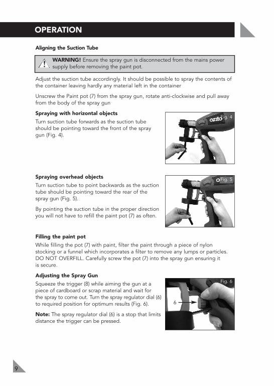
Aligning the Suction Tube
WARNING! Ensure the spray gun is disconnected from the mains powersupply before removing the paint pot.
Adjust the suction tube accordingly. It should be possible to spray the contents ofthe container leaving hardly any material left in the container
Unscrew the Paint pot (7) from the spray gun, rotate anti-clockwise and pull awayfrom the body of the spray gun
Spraying with horizontal objects
Turn suction tube forwards as the suction tubeshould be pointing toward the front of the spraygun (Fig. 4).
Spraying overhead objects
Turn suction tube to point backwards as the suctiontube should be pointing toward the rear of thespray gun (Fig. 5).
By pointing the suction tube in the proper directionyou will not have to refill the paint pot (7) as often.
Filling the paint pot
While filling the pot (7) with paint, filter the paint through a piece of nylonstocking or a funnel which incorporates a filter to remove any lumps or particles.DO NOT OVERFILL. Carefully screw the pot (7) into the spray gun ensuring itis secure.
Adjusting the Spray Gun
Squeeze the trigger (8) while aiming the gun at apiece of cardboard or scrap material and wait for the spray to come out. Turn the spray regulator dial (6)to required position for optimum results (Fig. 6).
Note: The spray regulator dial (6) is a stop that limitsdistance the trigger can be pressed.
OPERATION
Fig. 4
!!
Fig. 5
Fig. 6
6
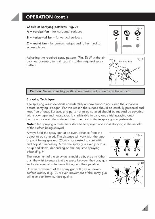
Choice of spraying patterns (Fig. 7)
A = vertical fan – for horizontal surfaces
B = horizontal fan – for vertical surfaces.
C = round fan – for corners, edges and other hard toaccess places.
Adjusting the required spray pattern (Fig. 8): With the aircap nut loosened, turn air cap (1) to the required spraypattern.
Caution: Never open Trigger (8) when making adjustments on the air cap.
Spraying Technique
The spraying result depends considerably on now smooth and clean the surface isbefore spraying is begun. For this reason the surface should be carefully prepared andkept free of dust. Surfaces and parts not to be sprayed should be masked by coveringwith sticky tape and newspaper. It is advisable to carry out a trial spraying ontocardboard or a similar surface to find the most suitable spray gun adjustments.
Note: Start spraying outside the surface to be sprayed and avoid stopping in the middleof the surface being sprayed.
Always hold the spray gun at an even distance from theobject to be sprayed. The distance will very with the typeof paint being sprayed, 20cm is suggested to start withand adjust if necessary. Move the spray gun evenly acrossor up and down, depending on the adjusted sprayingeffect (Fig. 9).
The movement of the spray gun should be by the arm ratherthan the wrist to ensure that the space between the spray gunand surface remains the same throughout the operation.
Uneven movement of the spray gun will give a unevensurface quality (Fig.10). A even movement of the spray gunwill give a uniform surface quality.
OPERATION (cont.)
1
2
Fig. 8
A B C
Fig. 7
Fig. 9
Fig. 10
10
Air cap nut

If coating material builds up on the nozzle (2) and air cap (1) (Fig.11) Remove the air cap nut and air cap (1). Clean both parts and around nozzle (2) withsolvent or water using a stiff brush.
If the nozzle (2) becomes blocked it can be removedby using a 9mm open ended spanner, carefullyunscrew from the paint head. Clean the nozzle (2) and remove any paint build up. Be careful not todamage the nozzle (2) as this will affect the spray gun performance.
Helpful Hints
• Do not spray outdoors on a windy day as the results may be unsatisfactory.
• Evenly control the speed of movement of the spray gun. A fast speed will givea thin coat and a slow speed will give a heavy coat.
• Only apply one coat at a time. If a further coat is required follow the paintmanufacturers instructions for re-coating and drying times.
• If spraying small areas or objects keep the output setting low as this will avoidexcessive use of paint and will minimise overspray.
• When spraying large areas or objects, it is best touse a crisscross pattern, either from left to rightthen up or down or vice-versa. This will ensuremaximum coverage (Fig.12).
• Avoid stopping and starting when spraying as thiscan lead to too much or not enough paint on a surface.
• To ensure edges are covered, commence sprayingjust to the side of an area being sprayed, continue and do not stop until thespray has gone past the opposite edge.
OPERATION (cont.)
11
Fig. 12
Fig. 111 2Air cap nut

CLEANING
12
!! WARNING! Always ensure that the Spray Gun is disconnected from themains power supply before making any adjustment or cleaning.
Clean After Every Use
After every use it is essential that you clean the gun thoroughly. This will prevent anyblockages occurring and provide reliable performance when you next come to use it.
1. Unplug the spray gun. Open trigger so that the coating material in spray gun runsback into the container.
2. Unscrew the container. Return remaining material into the material can.
3. Fill the paint pot with solvent or water.
Note: Only use solvent with a flash point of over 21°C.
4. Clean the paint pot and suction tube with a brush.
5. Screw container back in place. Plug the spray gun in and spray the solvent or waterinto a container.
6. Repeat the above procedure until clear solvent or water comes out of the nozzle.
7. Unplug the spray gun.
8. Then completely empty the paint pot. Always keep the container seal free ofcoating material and check for damage.
9. If the housing of the gun requires cleaning dip a cloth in the solvent or water,ensuring the cloth is not dripping, wipe the exterior of the spray gun.
10. Unscrew the air cap nut. Remove air cap (1). Clean the air cap and nozzle with stiffbrush and solvent or water.
11. Turn both the Quick release knobs (3) on both sidesof the spray gun to the “Unlock” position, pull andseparate the spray gun from the paint head (Fig. 13).
12. Clean the rear of the paint head with appropriatecleaning solution (Fig. 14). Turn the tube anti-clockwise and pull to disassemble from the painthead. Then clean the suction tube.
Fig. 13
Fig. 14
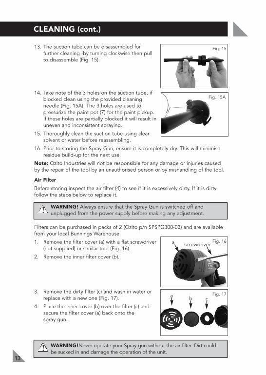
13. The suction tube can be disassembled forfurther cleaning by turning clockwise then pullto disassemble (Fig. 15).
14. Take note of the 3 holes on the suction tube, ifblocked clean using the provided cleaningneedle (Fig. 15A). The 3 holes are used topressurize the paint pot (7) for the paint pickup.If these holes are partially blocked it will result inuneven and inconsistent spraying.
15. Thoroughly clean the suction tube using clearsolvent or water before reassembling.
16. Prior to storing the Spray Gun, ensure it is completely dry. This will minimiseresidue build-up for the next use.
Note: Ozito Industries will not be responsible for any damage or injuries causedby the repair of the tool by an unauthorised person or by mishandling of the tool.
Air Filter
Before storing inspect the air filter (4) to see if it is excessively dirty. If it is dirtyfollow the steps below to replace it.
WARNING! Always ensure that the Spray Gun is switched off andunplugged from the power supply before making any adjustment.
Filters can be purchased in packs of 2 (Ozito p/n SPSPG300-03) and are availablefrom your local Bunnings Warehouse.
1. Remove the filter cover (a) with a flat screwdriver(not supplied) or similar tool (Fig. 16).
2. Remove the inner filter cover (b).
3. Remove the dirty filter (c) and wash in water orreplace with a new one (Fig. 17).
4. Place the inner cover (b) over the filter (c) andsecure the filter cover (a) back onto the spray gun.
WARNING!Never operate your Spray gun without the air filter. Dirt couldbe sucked in and damage the operation of the unit.
13
CLEANING (cont.)
Fig. 15
Fig. 16
Fig. 17
!!
!!
a screwdriver
a b c
Fig. 15A

14
MAINTENANCE
If required the paint head plunger can be removed and cleaned. This is a maintenancetask and should not be required on a frequent basis. If the paint has been allowed todry in the paint head or the spray gun has had a lot of use then removing andcleaning or replacing the plunger may restore the original spray gun performance.
1. Disassemble the paint head from the spray gun body by turning both the quickrelease knobs (3) on both sides of the spray gun to the "Unlock" position, pulland separate the paint head from the spray gun body.
2. Using a 8mm socket (not provided) unscrewcarefully and remove the paint head plungerassemble from the rear of the paint head (Fig. 18).
3. Clean the paint head plunger assembly and painthead and remove any paint using clear solvent or water.
4. After cleaning reassemble the plunger assembly inthe correct order (Fig. 19) and refit to the paint head.
5. Assemble the paint head to the spray gun body.
Note: Do not use abrasive material to clean the plunger as this may affect theperformance of the spray gun.
Fig. 18
Fig. 19

15
TROUBLE SHOOTING
Problem Cause Remedy
Little or no materialflow
Nozzle clogged Clean
Suction tube clogged Clean
Material spray regulator dial settingturned too low (-)
Increase spray regulator dialsetting (+)
Suction tube loose Insert
No pressure build up in paint pot Tighten paint pot
Air filter clogged Clean or replace
Material leaking Nozzle loose Tighten
Nozzle worn Replace
Nozzle seal worn Replace
Atomization is toocoarse
Viscosity of material too high Thin
Material volume too large Decrease spray regulatordial setting (-)
Material volume setting too high (+) Decrease spray regulatordial setting (-)
Nozzle clogged Clean
Air filter clogged Clean or replace
Spray jet pulsates Material in paint pot running out Refill
Air filter clogged Clean or replace
Applying too much material Adjust material flow orincrease movement ofspray gun
Too much overspray Gun too far from spray object Reduce distance
Pattern is very lightand splotchy
Moving the spray gun too fast Adjust material flow ordecrease movement ofspray gun
Too much material applied Decrease spray regulatordial setting (-)
Material build-up on air cap and nozzle Clean
Too little pressure build-up in container Tighten paint pot
Pattern runs or sags
16
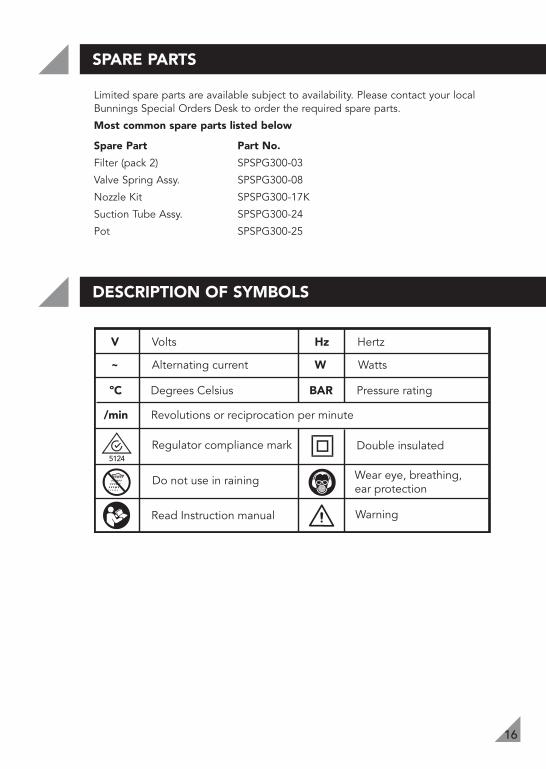
Limited spare parts are available subject to availability. Please contact your localBunnings Special Orders Desk to order the required spare parts.
Most common spare parts listed below
Spare Part Part No.
Filter (pack 2) SPSPG300-03
Valve Spring Assy. SPSPG300-08
Nozzle Kit SPSPG300-17K
Suction Tube Assy. SPSPG300-24
Pot SPSPG300-25
V Volts Hz Hertz
~ Alternating current W Watts
BAR Pressure rating
Read Instruction manual Warning
Double insulated
Wear eye, breathing, ear protection
Do not use in raining
Regulator compliance mark
/min Revolutions or reciprocation per minute
ºC Degrees Celsius
SPARE PARTS
DESCRIPTION OF SYMBOLS

CARING FOR THE ENVIRONMENT
Power tools that are no longer usable should not be disposedof with household waste but in an environmentally friendlyway. Please recycle where facilities exist. Check with your localcouncil authority for recycling advice.
Recycling packaging reduces the need for landfill and rawmaterials. Reuse of recycled material decreases pollution in theenvironment. Please recycle packaging where facilities exist.Check with your local council authority for recycling advice.
1 x Spray gun SGP-300 1 x Cleaning needle
1 x Viscosity cup1 x Instruction manual
AUSTRALIA (Head Office)1 - 23 Letcon Drive, Bangholme, Victoria, Australia 3175Telephone: 1800 069 486Facsimile: +61 3 9238 5588Website: www.ozito.com.auEmail: [email protected]
CONTENTS
OZITO INDUSTRIES PTY LTD
17

WARRANTYTHIS WARRANTY FORM AND CONFIRMED BUNNINGS REGISTER RECEIPT SHOULDBE RETAINED BY THE CUSTOMER AT ALL TIMES
The warranty is only made available by returning the product to your nearestBunnings Warehouse with a confirmed Bunnings register receipt.
PURCHASED FROM:________________________________________________
DATE PURCHASED: ________________________________________________
1 YEAR REPLACEMENT WARRANTYYour Ozito tool is guaranteed for a period of 12 months from the original date ofpurchase and is intended for DIY (Do it yourself) use only.
WARNING
The following actions will result in the warranty being void.
• Professional, Industrial or high frequency use.
• If the tool has been operated on a supply voltage other than that specified onthe tool.
• If the tool shows signs of damage or defects caused by or resulting from abuse,accidents or alterations.
• If the tool is disassembled or tampered with in any way.
Note: Warranty excludes consumable parts such as brushes, atomiser valves, spraynozzles, pistons, discs, drill bits, collets and router bits.
YOUR WARRANTY FORM SHOULD BE RETAINEDBY YOU AT ALL TIMES.
SHOULD YOU HAVE ANY QUESTIONS PRIOR TORETURNING YOUR PRODUCT FOR WARRANTY OR
REPAIR PLEASE TELEPHONE OUR CUSTOMERSERVICE HELPLINE:
Australia 1800 069 486New Zealand 0508 069 486
TO ENSURE A SPEEDY RESPONSE PLEASE HAVE THE MODEL NUMBERAND DATE OF PURCHASE AVAILABLE. AN OZITO CUSTOMER SERVICE
REPRESENTATIVE WILL TAKE YOUR CALL AND ANSWER ANY QUESTIONSYOU MAY HAVE RELATING TO THE WARRANTY POLICY OR PROCEDURE.