nzmn2−a250 article no.: 259094 sales text circuit ......type: nzmn2−a250 article no.: 259094...
TRANSCRIPT

Type: NZMN2−A250Article No.: 259094Sales text Circuit−breaker3p systems/cable prot.
Ordering information
Number of poles 3−pole
Description Terminal screws standard,terminals as accessories
Rated current = rated uninterruptedcurrent Iu A 250
Setting range
Overload releases Ir A 200...250
Switching capacity
Switching capacity kA 50
Release system Thermomagnetic release
Frame size NZM2
Notes concerning the product group
IEC/EN 60947−2
Adjustable overload release Ir
0.8 ... 1 × In (ex−works 0.8 × In)•
Adjustable short−circuit release Ii
6 ... 10 × I•
n
1

(ex−works 6 × I•
n)•
− NZM...−A40: 8 ... 10 × In (ex−works 8 × In)
Fixed short−circuit release Ii
350 A at In = 20 ... 32 A• 1280 A at In = 160 A (NZM1)•
Notes concerning the product group
Notes for terminals 262240
General
Standards IEC/EN 60947
Protection against direct contact Finger and back of hand proofto VDE 0106 Part 100
Climatic proofing
Damp heat, constant,according to IEC 60068−2−78Damp heat, cyclical to IEC60068−2−30
Ambient temperature
Ambient temperature, Storage °C ... 25...+70
Operation °C ... 25...+70
Mechanical shock resistance (IEC/EN60068−2−27)
Shock resistance g 20 (half−sinusoidal shock 20ms)
Safe isolation to VDE 0106 Part 101and Part 101/A1
Between auxiliary contacts and maincontacts V AC 500
between the auxiliary contacts V AC 300
Dimensions
Weight
Weight kg 2,345
Mounting position
Direction of incoming supply As required
Degree of protection
DeviceIn the operating controls area:IP20 (basic degree ofprotection)
2

EnclosuresWith insulating surround:IP40, with door couplingrotary handle: IP66
TerminationsTunnel terminal: IP10Phase isolator and stripterminal: IP00
Lifespan
Releases
Electrical lifespan at 8 A/230 V AC/70°C Operations 7500
Circuit−breakers
Rated impulse withstand voltage Uimp
Main contacts V 8000
Auxiliary contacts V 6000
Rated operational voltage Ue V AC 690
Overvoltage category/pollutiondegree III/3
Rated insulation voltage Ui V 1000
For use in IT electrical powernetworks V 690
Switching capacity
Rated short−circuit making capacity
240 V Icm kA 187
400/415 V Icm kA 105
440 V Icm kA 74
525 V Icm kA 53
690 V Icm kA 40
Rated short−circuit breaking capacityIcn
Icu to IEC/EN 60947 operatingsequence O−t−CO
240 V 50/60 Hz Icu kA 85
400/415 V 50/60 Hz Icu kA 50
415 V AC Icu kA 50
440 V 50/60 Hz Icu kA 35
525 V 50/60 Hz Icu kA 25
690 V 50/60 Hz Icu kA 20
500 V DC Icu kA 30
750 V DC Icu kA 30
Icu to IEC/EN 60947 operatingsequence O−t−CO−t−CO
3

240 V 50/60 Hz Ics kA 85
400/415 V 50/60 Hz Ics kA 50
415 V AC Ics kA 50
up to 440 V 50/60 Hz Ics kA 35
525 V 50/60 Hz Ics kA 25
up to 690 V 50/60 Hz Ics kA 5
690 V AC Ics kA 10
Maximum low−voltage h.b.c. fuse AgG/gL 355
Technical data, divergent from theproducts for the IECmarketSwitching capacity NAswitches (UL489, CSA 22.2 No. 5.1)
240 V 60 Hz kA 85
480V 60Hz kA 35
600 V 60 Hz kA 25
Utilization category to IEC/EN60947−2 A
Rated short−time withstand current
t = 0.3 s Icw kA 1,9
t = 1 s Icw kA 1,9
Lifespan, mechanical Operations 20000
Maximum operating frequency
Max. operating frequency Ops/h 120
Lifespan, electrical
AC−1
400/415 V 50/60 Hz Operations 10000
415 V Operations 10000
690 V 50/60 Hz Operations 7500
AC–−3
400/415 V 50/60 Hz Operations 6500
415 V Operations 6500
690 V 50/60 Hz Operations 5000
DC – −1
500 V DC Operations 7500
750 V DC Operations 7500
DC – 3
500 V DC Operations 3000
750 V DC Operations > 3000
Current heat loss per pole at Iu W 19
4

Current heat loss (3−pole) at Iu W 19
Overload releases
to IEC/EN 60947, VDE 0660
Temperature compensation toIEC/EN 60947 Residual error in therange −25 °C/+70 °C (referencetemperature 30 °C)
%/K 0
Temperature compensation 0
Frequency range ms < 10
Terminal capacities
Standard equipment Screw terminal
AccessoriesBox terminalTunnel terminalConnection on rear
Rated power of coil
Box terminal
Solid mm2 1 × (4 – 16)2 × (4 – 16)
Stranded mm2 1 × (25 – 185)2 × (25 – 70)
Tunnel terminal
Solid mm2 1 × 16
Stranded
Single hole mm2 1 × (25 – 185)
Bolt terminal and rear−sideconnection
Direct on the switch
Solid mm2 1 × (4 – 16)2 × (4 – 16)
Stranded mm2 1 × (25 – 185)2 × (25 – 70)
Al conductors, Cu cable
Tunnel terminal
Solid mm2 1 × 16
Stranded
Single hole mm21 × (25 – 185)je nach Kabelhersteller bis zu240 mm² anschließbar
Bolt terminal and rear−sideconnection
Direct on the switch
Solid mm2
5
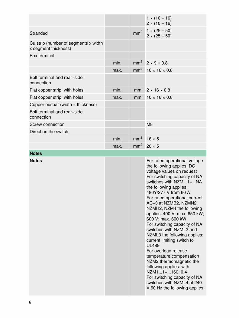
1 × (10 – 16)2 × (10 – 16)
Stranded mm2 1 × (25 – 50)2 × (25 – 50)
Cu strip (number of segments x widthx segment thickness)
Box terminal
min. mm2 2 × 9 × 0.8
max. mm2 10 × 16 × 0.8
Bolt terminal and rear−sideconnection
Flat copper strip, with holes min. mm 2 × 16 × 0.8
Flat copper strip, with holes max. mm 10 × 16 × 0.8
Copper busbar (width × thickness)
Bolt terminal and rear−sideconnection
Screw connection M8
Direct on the switch
min. mm2 16 × 5
max. mm2 20 × 5
Notes
Notes For rated operational voltagethe following applies: DCvoltage values on requestFor switching capacity of NAswitches with NZM...1−...NAthe following applies:480Y/277 V from 60 AFor rated operational currentAC−3 at NZMB2, NZMN2,NZMH2, NZM4 the followingapplies: 400 V: max. 650 kW;600 V: max. 600 kWFor switching capacity of NAswitches with NZML2 andNZML3 the following applies:current limiting switch toUL489For overload releasetemperature compensationNZM2 thermomagnetic thefollowing applies: withNZM1...1−...160: 0.4For switching capacity of NAswitches with NZML4 at 240V 60 Hz the following applies:
6

please enquireThe current heat loss per poleratings refer to the maximumcurrent rating of the framesize.
Mounting position
Vertical and 90° in all directions
With plug−in adapter NZM2, N(S)2: vertical, 90°right/left
with residual currentrelease NZM2: verticaland 90° to alldirections
With withdrawable unit NZM3, N(S)3: vertical,90° left NZM4, N(S)4: vertical with remoteoperator: NZM2, N(S)2, NZM3, N(S)3, NZM4,N(S)4: vertical and 90° to all directions
Overview
Basic equipmentBox terminal – – –Screw connection –
AccessoriesBox terminal – –Screw connection – –Tunnel terminalConnection on rearFlat conductor terminal – – –
Notes
For rated operational voltage switching on 3 contacts the following applies: DC correction factor forinstantaneous release response value NZM1: 1.25, NZM2: 1.35
Setting for Ii at DC = setting Ii AC/DC correction factor
Details apply for 3−pole system protection circuit−breaker with thermomagnetic releaseNZM(H)1(2)−A...
Switching of one pole via two series contacts Switching of one pole via three seriescontacts
7

For NA switch switching capacity with NZM...1−...(C)NA the following applies: 480 Y/277 V from 60AFor AC−3 rated operational current with NZM4 the following applies: 400 V: max. 650 kW; 690 V:max. 600 kWFor NA switch switching capacity with NZML2 and NZML3 the following applies: Current Limitingswitch to UL489For 3−pole system protection circuit−breaker the AC−3 specification is not applicableFor NA switch switching capacity with NZML4 at 240 V 60 Hz the following applies: on requestFor current heat loss per pole the specification refers to the maximum nominal current of the framesize.For 3−pole system protection circuit−breaker the followingapplies: 690 VFor 3−pole system protection circuit−breaker the following applies: 400/415 V 7500 switchingoperationsMaximum back−up fuse, if the expected short−circuit currents at the installation location exceed theswitching capacity of the circuit−breaker. 1600 A
Higher switching capacity on request
Notes
XSV = plug−in unit
XAV = withdrawable unit
TM = thermomagnetic
E = electronic
Dimensions
8
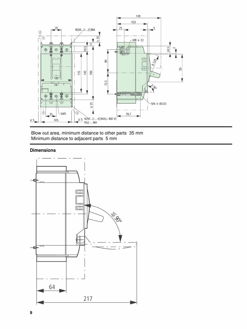
Blow out area, minimum distance to other parts 35 mm Minimum distance to adjacent parts 5 mm
Dimensions
9

Characteristic curve
System and line protection with NZM2
Characteristic curve
10

Let−through current îDLet−through energy I2t
Characteristic curve
11

1 half−shaft
Moeller GmbH, Hein−Moeller−Str. 7−11, D−53115 BonnE−Mail: [email protected], Internet: www.moeller.net, http://catalog.moeller.netHPL−C2007G V2.1 © 2007 by Moeller GmbH
12