nxg / nxg ii toolsuite software user manual · • nxg communications manual (a1a902399) • nxg...
TRANSCRIPT

Manual Number: A1A902291Version 5.0 August 2009
Siemens Energy & Automation, Inc.Large Drives A
500 Hunt Valley Road, New Kensington, PA, USA, 15068
Phone: 724-339-9500 Customer Support Phone: 1-800-333-7421 (24-hours) Fax: 724-339-9562 Customer Support Web: www.siemens.com/automation/support-request Web: www.siemens.com Customer Support: E-mail:[email protected]
NXG / NXG IITOOLSUITE SOFTWARE
USER MANUAL

For technical assistance and Field Service emergency support in the area nearest to you, please call the s 1.800.333.7421 toll-free number.
Version History
© 2009 by s No portion of this document may be reproduced either mechanically or electronically without the prior consent of s LD A
Version 1.0 (original) June 2006Version 2.0 August 2006Version 3.0 January 2007Version 4.1 (12281) February 2009Version 5.0 (13886) August 2009


NXG / NXG II ToolSuite Software User Manual Table of Contents
Table of ContentsSafety Precautions and Warnings....................................................................................... vii
About This Manual ............................................................................................................... ixSeparation of Manuals................................................................................................. ixReference Tools........................................................................................................... ixConventions Used in this Manual .................................................................................x
Chapter 1: NXG / NXG II ToolSuite Overview................................................................ 1-1Overview ....................................................................................................................1-1Starting ToolSuite.......................................................................................................1-7
Chapter 2: NXG / NXG II Drive Tool ...............................................................................2-1Drive Configuration Features.....................................................................................2-2Drive Variable Graphing Features .............................................................................2-3Drive Status Features..................................................................................................2-8Drive Control Features ...............................................................................................2-9
Drive Tool Pull Down Menu Features..............................................................................2-9Starting and Configuring the Drive Tool .................................................................2-13Setting Up Ethernet (TCP/IP) Communications ......................................................2-14Operating the Drive Tool ........................................................................................2-16
Fault or Alarm Displays..................................................................................................2-16Graphing Display ............................................................................................................2-21Time Scale Adjustment...................................................................................................2-27Freezing Graph on Fault .................................................................................................2-27Freezing Graph on Trigger..............................................................................................2-29Post Processing of Data...................................................................................................2-29
Chapter 3: NXG Debug Tool...............................................................................................3-1System Requirements .................................................................................................3-1Starting and Configuring the Debug Tool..................................................................3-1Operating the Debug Tool..........................................................................................3-4
A1A902291: Version 5.0 iiis

Table of Contents NXG / NXG II ToolSuite Software User Manual
Chapter 4: NXG SOP Utilities ............................................................................................ 4-1Introduction................................................................................................................ 4-1SOP Utility Tool Overview ....................................................................................... 4-1Starting the SOP Utility Tool..................................................................................... 4-4SOP Development Process ........................................................................................ 4-6Overview of the Compile Process ............................................................................. 4-7Input Source File........................................................................................................ 4-9
System Type Identification............................................................................................. 4-11SOP Source File.............................................................................................................. 4-13Input Flags ...................................................................................................................... 4-16Output Flags ................................................................................................................... 4-16Redefining Flag Names .................................................................................................. 4-18
Compiler Operation ................................................................................................. 4-18Output Hex File ....................................................................................................... 4-19Downloading a System Program (Hex File)............................................................ 4-19
Siemens LD A SOP Upload/Download Utility Method................................................. 4-20Terminal Emulation Method .......................................................................................... 4-21Termination .................................................................................................................... 4-21
Uploading a System Program (Hex File)................................................................. 4-25Reverse Compiler .................................................................................................... 4-25Header ...................................................................................................................... 4-32Combined Source / Hex File.................................................................................... 4-35
Chapter 5: NXG Configuration Update Utility Overview ............................................... 5-1System Requirements ................................................................................................ 5-1Starting and Configuring the Configuration Update Utility ...................................... 5-1Features Overview ..................................................................................................... 5-2
Copy Setup Files to Another Directory ............................................................................ 5-2Update Flash Disk Files.................................................................................................... 5-6Bootable Default Disk Procedure ..................................................................................... 5-9Copy Flash Disk to PC ................................................................................................... 5-14Make Bootable Copied Disk Procedure ......................................................................... 5-18Update ToolSuite Host Files on PC................................................................................ 5-22
iv A1A902291: Version 5.0s

NXG / NXG II ToolSuite Software User Manual Table of Contents
Chapter 6: Drive Server Setup/Status Utility.................................................................... 6-1Starting and Configuring the Configuration Update Utility ...................................... 6-1
Create a New Server Connection...................................................................................... 6-2Setup / Status Application Operation......................................................................... 6-5
Status Screen..................................................................................................................... 6-5Menu Functions ................................................................................................................ 6-6
Setup Menu ............................................................................................................................ 6-6Server Maintenance ............................................................................................................... 6-7Config Menu .......................................................................................................................... 6-8Security Menu ...................................................................................................................... 6-10
Chapter 7: High Availability Drive Tool ........................................................................... 7-1Connection to Drive Tool .......................................................................................... 7-1Selecting Desired Control System ............................................................................. 7-3
Appendix A: Operators and Precedence .......................................................................... A-1Operators and Precedence......................................................................................... A-1Ladder Logic Translation.......................................................................................... A-4
Appendix B: Ethernet Connections....................................................................................B-1Direct Connection ......................................................................................................B-1
Required Items for a Single Ethernet Direct Connection ................................................ B-1Required Items for a Single PC Multiple Drive Ethernet Connection Support.......................... B-1Configuring a PC to Work with a Direct Connection B-2
Windows® XP /2000 ............................................................................................................ B-2Windows® Vista .................................................................................................................. B-7
Appendix C: Glossary ........................................................................................................ C-1
Appendix D: Abbreviations ............................................................................................... D-1
Notes ..................................................................................................................................... N-1
Reader Comments Form .................................................................................................... R-1
Startup/Warranty Registration and Service Solutions .................................................. W-1
A1A902291: Version 5.0 vs

Table of Contents NXG / NXG II ToolSuite Software User Manual
vi A1A902291: Version 5.0s

NXG / NXG II ToolSuite Software User Manual Safety Precautions and Warnings
The Perfect Harmony Variable Frequency Drives are designed with considerable thought to personal safety. However, as with any piece of high power equipment, there are numerous internal connections that present potentially lethal voltages. In addition, some internal components are thermally hot to the touch. Follow the warnings below when working in or near the system.
Safety Precautions and Warnings
Danger - Electrical Hazards!• Always follow the proper lock-out/tag-out procedures before beginning any maintenance or trouble-
shooting work on the drive.• Always follow standard safety precautions and local codes during installation of external wiring. Pro-
tective separation must be kept between extra low voltage (ELV) wiring and any other wiring as spec-ified in IEC61800-5-1.
• Always work with one hand, wear insulated or rubber safety shoes, and wear safety glasses. Also, always work with another person present.
• Always use extreme caution when handling or measuring components that are inside the enclosure. Be careful to prevent meter leads from shorting together or from touching other terminals.
• Use only instrumentation (e.g., meters, oscilloscopes, etc.) intended for high voltage measurements (that is, isolation is provided inside the instrument, not provided by isolating the chassis ground of the instrument).
• Never assume that switching off the input disconnect will remove all voltage from internal compo-nents. Voltage is still present on the terminals of the input disconnect. Also, there may be voltages present that are applied from other external sources.
• Never touch anything within the cabinets until verifying that it is neither thermally hot nor electrically alive.
• Never remove safety shields (marked with a HIGH VOLTAGE sign) or attempt to measure points beneath the shields.
• Never run the drive with cabinet doors open. The only exception is the control cabinet which contains extra low voltages (ELV).
• Never connect any grounded (i.e., non-isolated) meters or oscilloscopes to the system.• Never connect or disconnect any meters, wiring, or printed circuit boards while the drive is energized.• Never defeat the instrument’s grounding.• Only qualified individuals should install, operate, troubleshoot, and maintain this drive. A qualified
individual is “one familiar with the construction and operation of the equipment and the hazards involved.”
• Hazardous voltages may still exist within the cabinets even when the disconnect switch is open (off) and the supply power is shut off.
A1A902291: Version 5.0 viis

Safety Precautions and Warnings NXG / NXG II ToolSuite Software User Manual
Additional safety precautions and warnings appear throughout this manual. These important messages should be followed to reduce the risk of personal injury or equipment damage.
∇ ∇ ∇
Warning!• Always comply with local codes and requirements if disposal of failed components is
necessary (for example, CPU battery, capacitors, etc.).• Always ensure the use of an even and flat truck bed to transport the drive system. Before unloading,
be sure that the concrete pad is level for storage and permanent positioning.• Always confirm proper tonnage ratings of cranes, cables, and hooks when lifting the
drive system. Dropping the cabinet or lowering it too quickly could damage the unit.• Never disconnect control power while medium voltage is energized. This could cause
severe system overheating and/or damage.• Never store flammable material in, on, or near the drive enclosure. This includes
equipment drawings and manuals.• Never use fork trucks to lift cabinets that are not equipped with lifting tubes. Be sure
that the fork truck tines fit the lifting tubes properly and are the appropriate length.
ESD Sensitive Equipment! • Always be aware of electrostatic discharge (ESD) when working near or touching components inside
the cabinet. The printed circuit boards contain components that are sensitive to static electricity. Han-dling and servicing of components that are sensitive to ESD should be done only by qualified person-nel and only after reading and understanding proper ESD techniques. The following ESD guidelines should be followed. Following these rules can greatly reduce the possibility of ESD damage to PC board components.
• Always transport static sensitive equipment in antistatic bags.• Always use a soldering iron that has a grounded tip. Also, use either a metallic vacuum-style plunger
or copper braid when desoldering.• Make certain that anyone handling printed circuit boards is wearing a properly grounded static strap.
The wrist strap should be connected to ground through a 1 megohm resistor. Grounding kits are avail-able commercially through most electronic wholesalers.
• Static charge buildup can be removed from a conductive object by touching the object to a properly grounded piece of metal.
• When handling a PC board, always hold the card by its edges.• Do not slide printed circuit boards across any surface (e.g., a table or work bench). If possible, per-
form PCB maintenance at a workstation that has a conductive covering that is grounded through a 1 megohm resistor. If a conductive tabletop cover is unavailable, a clean steel or aluminum tabletop is an excellent substitute.
• Avoid plastic, Styrofoam™, vinyl and other non-conductive materials. They are excellent static gen-erators and do not give up their charge easily.
• When returning components to Siemens LD A, always use static-safe packing. This limits any further component damage due to ESD.
viii A1A902291: Version 5.0s

NXG / NXG II ToolSuite Software User Manual About This Manual
Separation of Manuals
This manual is one component of a series of manuals intended for use with the NXG / NXG II ToolSuite Software Package. Each part in this series is for use by individuals having unique job functions and qualifications. The manuals in this series are listed below:
• NXG Control Manual (A1A19001588)
• WCIII-HA NXG II Control Manual (A5E02328853A)
• NXG Communications Manual (A1A902399)
• NXG Control Manual (A1A19001588)
The NXG Communications Manual (A1A902399) describes the NXG Control Communication Board, which enables network communication via a variety of protocols and enables modem connection. This manual is used for non-High Availability (HA) VFD drives.
For High Availability VFD Drives, the Drive Server Setup/Status Utility discussed in Chapter 6 of the NXG / NXG II ToolSuite Software User Manual (A1A902291) defines the setup requirements for computer-to-computer communication where one of the computers is hosting a Drive Server. The High Availability Drive Server description is included in an appendix to the WCIII-HA Control Manual (A5E02328853A).
The NXG Control Manual (A1A19001588) and the WCIII-HA Control Manual (A5E02328853A) describe the Control System for non-HA and HA VFD Systems, respectively. The Harmony family of drives is a collection of Medium Voltage Drives having different power topologies and cooling methods. The unifying factor with the drives is the NXG / NXG II Control System.
Reference ToolsMany steps have been taken to promote the use of this manual as a reference tool. Reference tools include the following:
• A thorough table of contents for locating particular sections or subsections
• Chapter number thumb nails in the outer margins for easy location of chapters
• Special text styles are applied to easily differentiate between chapters, sections, subsections, regular text, parameter names, software flags and variables, and test points
• A comprehensive index
About This Manual
A1A902291: Version 5.0 ixs

About This Manual NXG / NXG II ToolSuite Software User Manual
Conventions Used in this ManualThe following conventions are used throughout this manual:
• The terms “Perfect Harmony,” “VFD,” “variable frequency drive,” and “drive” are used interchangeably throughout this manual.
• Chapter numbers are highlighted in the outer margins to facilitate referencing (see margin).
• Test points and terminal block designations are shown in uppercase, boldface (e.g., TB1A).
All manuals contain a readers’ comments form. Please complete these forms and return them to us. Monitoring your feedback allows us to continue to exceed your expectations and provide complete, effective, easy-to-use product documentation.
∇ ∇ ∇
Note: Hand icons in the left margin alert readers to important operational or application information that may have special significance. The associated text is enclosed in a border for high visibility.
Attention! Attention icons in the left margin alert readers to important safety and operational precautions. These notes warn readers of potential problems that could cause equipment damage or personal injury. The associated text is enclosed in a border for high visibility.
Caution - Electrical Hazard! Electrical hazard icons in the outer margins alert readers to important safety and operational precautions. These notes warn readers of dangerous voltages, potential safety hazards, or shock risks that could be life threatening. The associated text is enclosed in a border for high visibility.
ESD Warning! These icons in the left margin alert readers to static sensitive devices. Proper electrostatic discharge precautions should be taken before proceeding or handling the equipment.
x A1A902291: Version 5.0s

NXG / NXG II ToolSuite Software User Manual NXG / NXG II ToolSuite Overview
1
CHAPTER1 NXG / NXG II ToolSuite Overview
IMPORTANT!
Ensure that Version 2.0 of Microsoft‘s® .NET Framework is installed prior to installing ToolSuite.
Non-Siemens personnel can obtain .NET Framework by visiting the Microsoft® website and downloading it from there. Siemens personnel can download this application from a designated Siemen’s server.
1.1 OverviewThe NXG / NXG II ToolSuite is a PC-based high-level Graphical User Interface (GUI) application that integrates various software tools used for NXG/NXG II based drives. ToolSuite, equipped with the Microsoft® Windows Operating System, allows naviagation through a drive’s features by using a PC and a mouse or by using a touch screen (instead of a keypad) – allowing you to monitor and control that drive’s functions quickly and easily. The NXG Control and the PC running the NXG ToolSuite software, interface with one another using Ethernet and TCP/IP protocol.
ToolSuite contains the following tools:
• Drive Tool –Chapter 2 (for non - High Availability VFDs)
• Debug Tool – Chapter 3
• SOP Utilities – Chapter 4
• Configuration Update Utility – Chapter 5
• Drive Server Setup / Status Utility - Chapter 6 (for High Availability VFDs)
• High Availability Drive Tool - Chapter 7
A1A902291: Version 5.0 1-1s

NXG / NXG II ToolSuite Overview NXG / NXG II ToolSuite Software User Manual
1
1.2. Installation ProcedurePerform the following steps to install ToolSuite.1. Insert the Siemens NXG ToolSuite CD into your PC’s CD drive. Open Windows Explorer and select the CD Drive.
2. Double Click on the file ToolSuite Setup vx.x.exe (vx.x will vary based on the latest software version
3. The “ToolSuite Installation Wizard” dialog boxes should appear as shown above. Follow the instruction and select the “Next>” button.
1-2 A1A902291: Version 5.0s

NXG / NXG II ToolSuite Software User Manual NXG / NXG II ToolSuite Overview
1
4. This dialog box shows the version information for all of the ToolSuite software components. Select the“Next>” button.
5. Select the “Next” button to begin the installation.
A1A902291: Version 5.0 1-3s

NXG / NXG II ToolSuite Overview NXG / NXG II ToolSuite Software User Manual
1
6. After clicking “Next”, the Updating System window appears.1-4 A1A902291: Version 5.0s

NXG / NXG II ToolSuite Software User Manual NXG / NXG II ToolSuite Overview
1
7.If the installation was successful, the following dialog box appears. Click “Finish” to exit the installation,8. After the clicking “Finish” a Installer Information pop-up displays on the PC’s monitor prompting you to re-start your computer. Choose “Yes” to complete configuration changes or “No” if you wish to manually restart your PC at a later time.
9. If the installation was interrupted or stopped by the user before the ToolSuite software fully installs, the following dialog box appears.
10. Click “OK” to proceed.
A1A902291: Version 5.0 1-5s

NXG / NXG II ToolSuite Overview NXG / NXG II ToolSuite Software User Manual
1
11. To re-run the installation, follow the steps as described in the previous pages. Upon selecting the ToolSuiteSetup v4.1.0.exe file, the Application Maintenance window displays as indicated below.
12. Make the desired selection and proceed as prompted by the software.
1-6 A1A902291: Version 5.0s

NXG / NXG II ToolSuite Software User Manual NXG / NXG II ToolSuite Overview
1
1.3 Starting ToolSuiteThe ToolSuite installation program places an icon on your PC’s desktop
1. Double click the icon to start the ToolSuite.
2. The ToolSuite Splash Screen appears.
A1A902291: Version 5.0 1-7s

NXG / NXG II ToolSuite Overview NXG / NXG II ToolSuite Software User Manual
1
3. Once the ToolSuite is started, a window displays showing the Drive Tools, Debug Tool, and Utilities Tabs. At this point invoke one of the Tools listed below:• Drive Tool - Refer to Chapter 2
• Debug Tool – Refer to Chapter 3
• Utilities – Refer to Chapters 4-6
• HA Drive Tool - Refer to Chapter 7
∇ ∇ ∇
1-8 A1A902291: Version 5.0s

NXG / NXG II ToolSuite Software User Manual NXG / NXG II Drive Tool
2
The sections that follow provide additional information about each of these features.
CHAPTER
2 NXG / NXG II Drive ToolThe NXG / NXG II Drive Tool is the main graphical interface to the non-HA Drive. Its purpose is to manage all of the drive features and provide the user with a user-friendly view of the drive. To read about the HA Drive Tool, refer to Chapter 7 of this manual.
The Drive Tool’s main features include:
1. Drive Configuration2. Drive Variable Graphing3. Drive Status
4.Drive Control
4DRIVE CONFIGURATION
DRIVE VARIABLE GRAPHING
DRIVE STATUS
DRIVE CONTROL
A1A902291: Version 5.0 2-1s

NXG / NXG II Drive Tool NXG / NXG II ToolSuite Software User Manual
2
2.1 Drive Configuration Features• Folders for each drive configuration category (matches the drive’s keypad Quick Keys)
• Icon colors:
o If multiple configuration files option is NOT enabled then:
GREEN = defaultRED = changed from default
o If multiple configuration files option IS enabled then:
GREEN = master config file parameter and defaultRED = master config file parameter changed from defaultLIGHT BLUE = secondary config file parameter and defaultDARK BLUE = secondary config file parameter changed from default
• On screen help and ID identifier (matches the keypad IDs for Speed Menus)
• All parameters editing assisted by min, max limits, and defaults
2-2 A1A902291: Version 5.0s

NXG / NXG II ToolSuite Software User Manual NXG / NXG II Drive Tool
2
2.2 Drive Variable Graphing FeaturesThese drive variable graphing features are accessible via the Main Toolbar options and their respective submenus. See the pictures below.
• Adjustable Time Scale
• Pick List Selectable Variables
• Graphing Capability Of Up To 10 Variables
A1A902291: Version 5.0 2-3s

NXG / NXG II Drive Tool NXG / NXG II ToolSuite Software User Manual
2
• Customizable Graphics
• Individual Variable Offsets and Variable Scaling
2-4 A1A902291: Version 5.0s

NXG / NXG II ToolSuite Software User Manual NXG / NXG II Drive Tool
2
• Fonts, Color, Styles
• Freeze Graphics, Freeze Graph On Fault
• Freeze On Settable Trigger
A1A902291: Version 5.0 2-5s

NXG / NXG II Drive Tool NXG / NXG II ToolSuite Software User Manual
2
• Zoom Graph
• Printable Graphics
‘Zoomed In’ portion of graph selected using the ToolSuite Zoom Graph feature
Graph frozen - user-selected portion of graphdesired to view using the Zoom Graph feature
2-6 A1A902291: Version 5.0s

NXG / NXG II ToolSuite Software User Manual NXG / NXG II Drive Tool
2
• Exportable Graphics
o Export: MetaFile, BMP, JPG, PNG, Text / Data Only
o Export Destination: ClipBoard, File, Printer
o Object Size: No Specific Size, or Millimeters, Inches, Points (Width / Units)
A1A902291: Version 5.0 2-7s

NXG / NXG II Drive Tool NXG / NXG II ToolSuite Software User Manual
2
2.3 Drive Status Features
• 7 Programmable Display Variables
• Pick List Selectable Variables
• First 4 Synchronized To Keypad
• Fault and Alarm Indicators (Traffic Lights Red = Fault, Yellow = Alarm, Display Flashes)
Programmable Display Variables
Traffic Light Indicators
2-8 A1A902291: Version 5.0s

NXG / NXG II ToolSuite Software User Manual NXG / NXG II Drive Tool
2
2.4 Drive Control Features• Manual Start Button
• Auto Start Button
• Stop Button
• Fault Reset Button
• Show Active Fault / Alarm Log Button
2.4.1 Drive Tool Pull Down Menu Features
File:
• Load Configuration Files
• Reset To Factory Defaults
• Create Config File
• Save Data
• Save Data As
• Display Active Config File
• Drive Parameter Data
o Print Data
o Write Data To Text File
o Search by ID
o Search by Text
• Set Factory Defaults
• Options
• Enter manual speed: Ctrl+D1
• System Program
o Download New System Program
o Display System Program Name
o Upload System Program
• Network
o Make Network 2 same as Network 1
o View Network Module Types
View:
• Configuration Window
• Graphics Window
• Status Window
1. When manually entering the drive speed, be aware that although the drive may be using speed limits set by Speed Limits set 1, Speed Limits set 2, or Speed Limits set 3, the Drive Tool limits the manually entered speed value to those values established by Speed Limit set 1 exclusively. Therefore, the maximum and minimum allowable values of entered speed will be limited to those values established by Speed Limits set 1.
A1A902291: Version 5.0 2-9s

NXG / NXG II Drive Tool NXG / NXG II ToolSuite Software User Manual
2
Security:
• Enter Security Code from Toolbar Menu or by:Ctrl+S
• Security Edit• Change Security Code• Security Level Clear
Status:
• Elapsed Time
o Preset
o Reset
o Display
• Input kW Hours Consumed
o Preset
o Reset
o Display
• Output kW HoursConsumed
o Preset
o Reset
o Display
• Cells
o Display Cell Status
o Display Bypass Status
o Reset Bypassed Cells
• Set Clock Time
2-10 A1A902291: Version 5.0s

NXG / NXG II ToolSuite Software User Manual NXG / NXG II Drive Tool
2
Logs:
• Fault LogEnglish
o Display Log
o Store Log in File
o Print Log
Drive Language
o Display Log*
o Store Log in File*
o Print Log*
Clear Log
• Historic LogEnglish
o Display Log
o Store Log in File
o Print Log
Drive Language
o Display Log*
o Store Log in File*
o Print Log*
Clear Log
• Event LogEnglish
o Display Log
o Store Log in File
o Print Log
A1A902291: Version 5.0 2-11s

NXG / NXG II Drive Tool NXG / NXG II ToolSuite Software User Manual
2
Drive Language
o Display Log*
o Store Log in File*
o Print Log*
Clear Log
Diagnostics
• Speed Test
o Start Speed Test
o Stop Speed Test
Calibration
• Auto-Tune
Note: Items designated with an asterisk * are only available when ToolSuite is connected to a drive running NXG Version 5 .0 or later software and the selected drive language is other than English.
2-12 A1A902291: Version 5.0s

NXG / NXG II ToolSuite Software User Manual NXG / NXG II Drive Tool
2
2.5 Starting and Configuring the Drive ToolIf no configured Drives exist, it will be necessary to configure a new one. To do this, click the “New” button in the “Drive Configurator” area of the ToolSuite dialog box shown below.
In the new dialog box shown below, select the “Use Default Values” Operation Type. Select “Harmony” from the Type Selection drop-down list and enter a drive name in the field provided directly under “Drive Name”. Click the “OK” button.
The ToolSuite dialog box will reappear, now showing the newly configured drive. Refer to Appendix B Ethernet Connections, which contains the information for a PC-to-drive communications setup.
Click “New”
Type the desired name of the drive in this field.
A1A902291: Version 5.0 2-13s

NXG / NXG II Drive Tool NXG / NXG II ToolSuite Software User Manual
2
2.6 Setting Up Ethernet (TCP/IP) Communications
Go to each drive and use that drive’s keypad to set the menu items of the “TCP/IP setup” menu (ID = 9300). The menu items below must be updated based on the settings unique to your network:
Table 2-1: Table Network Settings
Next, set the TCP/IP address in the Drive Tool to the same value as the drive, so that it will communicate with the drive. The following figure shows the drive’s TCP/IP address highlighted. Change this value to match that of the drive to which you wish to communicate. Double-click the “TCP/IP server name” text or its adjacent icon to edit its value.
IMPORTANT! To use the Drive Tool to control drives through an existing network, assign a unique IP address to each drive.
Menu Item Menu ID Default Setting Custom Setting (Write yours here)
IP Address 9310 172.17.20.16
Subnet Mask 9320 255.255.0.0
Gateway Mask 9330 172.17.1.1
Enter Data
Double-Click
2-14 A1A902291: Version 5.0s

NXG / NXG II ToolSuite Software User Manual NXG / NXG II Drive Tool
2
If the PC on which the Drive Tool runs already has the correct network settings for the LAN, the Drive Tool will start communicating with the drive within a few seconds of the time that you make this change. If the settings are not correct, then enter new network settings by simply right clicking the TCP/IP server name to display the “String Entry” pop-up window and enter the necessary information.
Afterwards, the Configuration window will display a tree of several folders, and the Graphics and Status windows will start displaying data similar to that shown in the following graphic.
A1A902291: Version 5.0 2-15s

NXG / NXG II Drive Tool NXG / NXG II ToolSuite Software User Manual
2
2.7 Operating the Drive Tool Now that your Drive Tool is installed and operational, please take some time to become familiar with its features, and how to use them.
2.7.1 Fault or Alarm Displays
When a fault or an alarm condition exists, the Drive Tool window flashes to annunciate the existence of a Fault/Alarm.
The Drive Tool also displays traffic lights in the lower right-corner of the display window.
In addition, the word “Fault” will appear under Mode within the Status window. .
To display the most recent Fault Alarms, go to the Menu Bar and Select “Fault Log → Display Log...”
The ToolSuite software displays a pop-up window that informs the user that the Fault Log is currently being uploaded. Once the information is uploaded, a dialog box that lists the Fault Alarms in the order of their occurrence appears.
Note: The Drive Tool flashing window feature can be disable via the “Configuration → Options” pull down menu.
Note: Red lights indicate Faults and yellow lights represent Alarms.
2-16 A1A902291: Version 5.0s

NXG / NXG II ToolSuite Software User Manual NXG / NXG II Drive Tool
2
A1A902291: Version 5.0 2-17s

NXG / NXG II Drive Tool NXG / NXG II ToolSuite Software User Manual
2
If an alarm has reset itself, the reset time will be noted. If a fault condition no longer persists, you can reset the fault by clicking the “Reset” button in the Drive Tool window.
If all faults have been reset, the Drive Tool window will appear as shown above, without flashing.
Note: The yellow traffic light indicates that an alarm condition still persists.
Perform Manual Reset
YELLOW TRAFFIC LIGHT
2-18 A1A902291: Version 5.0s

NXG / NXG II ToolSuite Software User Manual NXG / NXG II Drive Tool
2
You can change a drive parameter by selecting the desired parameter from within the configuration window and double clicking on it. This will cause a dialog box similar to the one below to appear. You can then type in the desired value (some parameters will be changed from a pick list). The limits, default value, and current value are displayed, along with a more complete parameter description than those shown in the configuration window. You can enter a comment as a record of the change if desired. The “Set to Default” button will restore the default value. The “Help” button is not currently supported.
display Select Item WindowClick on DEMD parameter to
A1A902291: Version 5.0 2-19s

NXG / NXG II Drive Tool NXG / NXG II ToolSuite Software User Manual
2
Desired values may also be edited by selecting a directory (folder) or a specific variable parameter by right clicking the icon and selecting the appropriate submenu item as shown below. The submenu provides not only the means to change values, but to search for specific IDs as well. Parameters that are changed from the default value will appear as reddish icons and parameters set to their default values are displayed as greenish icons.
Note: To permanently change a drive parameter, select “Configuration” → “Save Data” from the pull down menu bar of the Drive Tool window.
2-20 A1A902291: Version 5.0s

NXG / NXG II ToolSuite Software User Manual NXG / NXG II Drive Tool
2
2.7.2 Graphing Display
A list of the variables that you can display in the ToolSuite is given in Table 2-2. A total of ten variables can be displayed at the same time. Select variables with the Graphing submenu (ID# 10). Each variable has a scale factor and an offset. The Y-axis display range is –1.0 to +1.0. All variables are required to be scaled within this range to be visible on the screen. The value shown on the screen is the actual value divided by the chosen scale factor. Unless otherwise indicated, the variables are in per unit; hence the default Scale Factor of 1.0 is satisfactory for most variables.
The offset parameter shifts the zero point of the variable up or down on the plot window. For most variables, the default offset of 0.0 is sufficient.
A1A902291: Version 5.0 2-21s

NXG / NXG II Drive Tool NXG / NXG II ToolSuite Software User Manual
2
Table 2-2: List of Variables Available for Display
Variable Name Description
Ids Measured motor magnetizing current
Iqs Measured motor torque current
Ids reference Motor magnetizing current command
Iqs reference Motor torque current command
Iqs reference filtered Filtered torque current command
Flux DS Estimated motor flux
Flux QS Flux input to PLL for motor speed and flux angle estima-tion (typically 0.0)
Vds reference D-axis voltage command (or output of magnetizing cur-rent regulator)
Vqs reference Q-axis voltage command (or output of torque current regu-lator)
Output frequency Drive output frequency in rad/sec
Slip frequency Estimated motor slip frequency in rad/sec
Motor speed (frequency-slip) Estimated motor speed in rad/sec
Motor speed filtered Filtered motor speed in rad/sec
RLoss for braking Equivalent motor resistance during dual frequency braking
XLoss for braking Equivalent motor inductance during dual frequency brak-ing
Field weakening limit Field weakening torque current limit
Dual Frequency Braking Limit Current limit during dual frequency braking
Maximum Current Limit Maximum torque limit (at output of speed regulator)
Minimum Current Limit Minimum torque limit (at output of speed regulator)
Iq gain Speed regulator enable signal
Ua reference Phase A output voltage command
Ub reference Phase B output voltage command
Uc reference Phase C output voltage command
Flux D loss filtered D-axis flux component at the loss inducing frequency
Flux Q loss filtered Q-axis flux component at the loss inducing frequency
2-22 A1A902291: Version 5.0s

NXG / NXG II ToolSuite Software User Manual NXG / NXG II Drive Tool
2
Id loss filtered D-component of current at loss frequencyIq loss filtered Q-component of current at loss frequency
W loss Loss inducing frequency in rad/sec
Ws filtered Filtered drive output frequency
Theta loss Flux angle of the loss inducing frequency in radians
Flux DS Filtered Filtered motor flux
Ids Filtered Filtered motor magnetizing current
Iqs Filtered Filtered motor torque current
Vd Loss Magnitude of loss inducing voltage
Ids No Load No-load motor current
Stator Resistance Stator resistance
Wp Reference Pulsation frequency in rad/sec
Output Vector Angle Motor flux angle in radians
Volt Second Phase A Measurements Measured phase A motor volt-seconds
Volt Second Phase B Measurements Measured phase B motor volt-seconds
Volt Second Phase C Measurements Measured phase C motor volt-seconds
Ia Current Measurements Measured phase A motor current
Ib Current Measurements Measured phase B motor current
Ic Current Measurements Measured phase C motor current
Ids Measured Current After Synch Filter (V/Hz)
Not used
Iqs Measured Current After Synch Filter (V/Hz)
Not used
Raw Speed Demand *Raw speed demand in rad/sec
Auxiliary Demand Before Ramp *Auxiliary demand before speed ramp in rad/sec
Auxiliary Demand After Ramp *Auxiliary demand after speed ramp in rad/sec
Speed Demand *Ran Speed demand & Aux demand before ramp
Speed Profile Output *Output of speed profile routine in rad/sec
Variable Name Description
A1A902291: Version 5.0 2-23s

NXG / NXG II Drive Tool NXG / NXG II ToolSuite Software User Manual
2
Critical Speed Avoidance Output *Critical speed avoidance output in rad/secPolarity Change Output *Output of polarity change function in rad/sec
Minimum Demand Output *Output of minimum limit routine in rad/sec
Ramp Output *Output of speed ramp function in rad/sec
Speed Demand At Limit Input *Input signal to speed (maximum) limit function in rad/sec
Speed Reference *Motor speed reference in rad/sec
Raw Flux Demand Flux demand from menu
Flux Ramp Output Output of flux ramp controller
Energy Saver Output Output of energy saver controller
Field Weakening Output Output of field weakening controller
Flux Reference Flux reference
Id Input Current Real component of input current
Iq Input Current Reactive component of input current
Phase A Input Current Phase A input current
Phase B Input Current Phase B input current
Phase C Input Current Phase C input current
Phase A Input Voltage Phase A input voltage
Phase B input voltage Phase B input voltage
Phase C Input Voltage Phase C input voltage
Zero Sequence Average RMS value of zero sequence component in input voltage
Negative Sequence D Voltage D-component of negative sequence in input voltage
Negative Sequence Q Voltage Q-component of negative sequence in input voltage
D Voltage Amplitude of voltage of line voltage (taking transformer tap setting into account)
Q Voltage Q-axis component voltage used to drive input PLL for frequency estimation.
Input Frequency Input (line frequency) in rad/sec
Input Power Average (kilowatts) Input power
Input Power Factor Input side power factor
Ah Harmonic Coefficient Amplitude of A-component of harmonic chosen using menu setting
Bh Harmonic Coefficient Amplitude of B-component of harmonic chosen using menu setting
Variable Name Description
2-24 A1A902291: Version 5.0s

NXG / NXG II ToolSuite Software User Manual NXG / NXG II Drive Tool
2
Transformer Thermal Level Output torque limit set by transformer thermal limit regulatorOne Cycle Reactive Current Level Input one cycle reactive current trip level
Single Phasing Current Level Output torque limit set by input single-phasing regulator
Under Voltage level Output torque limit set by input undervoltage regulator
Input Side Flux Input voltage converter to flux for Up Transfer
Line Flux Vector Angle Angle of input voltage in radians
Output Neutral Voltage Input side neutral voltage
Sync Motor Field Current Field current command (for synchronous motor)
Encoder Speed Encoder speed output
Motor Voltage Motor voltage (or drive output voltage)
Output Power Average (kilowatts) Output Power
Phase A Filter Current Filter current in A phase
Phase B Filter Current Filter current in B phase
Phase C Filter Current Clamped Filter current in C phase
Measured Phase A Volts Actual Drive voltage A phase
Measured Phase B Volts Actual Drive voltage B phase
Measured Phase C Volts Actual Drive voltage C phase
Measured Output Neutral Voltage Drive neutral voltage
Max Available Output Volts Max available output voltage
Input Reactive Power (kVAR) Input kVAR
Drive Efficiency Efficiency
Drive State Drive state
Up Transfer State Up transfer state variable
Down Transfer State Down transfer state variable
Drive Internal Losses Difference between output and input power
Excess Input Reactive Current Input to one-cycle algorithm, indicating the input reactive current allowance before a trip condition exists
Speed Droop Amount of droop subtracted from the speed demand (rad/sec)
Precharge State Variable State machine value for precharge transitions
Precharge Voltage Input voltage during precharge
Input Real Current Filtered real component of input current
Variable Name Description
A1A902291: Version 5.0 2-25s

NXG / NXG II Drive Tool NXG / NXG II ToolSuite Software User Manual
2
* Refer to the Command Generator Diagram, DWG 459713, to see where these variables are used in the control code.
Input Reactive Current Filtered reactive component of input current
AFE Reactive Current Reference Desired input reactive current in AFE system
AFE Input Voltage Feed-forward Feed forward voltage term of AFE control
AFE Real Current Feed-forward Feed forward current term of AFE control
Input Id Unfiltered Real current before filtering
Input Iq Unfiltered Reactive current before filtering
AFE kVAR Input reactive power on AFE
AFE kW Input real power on AFE
Maximum Demand Output Clamped speed demand (at the maximum limit) at the ramp input
SMDC Mode State Variable SMDC startup state machine variable • Disabled = 0• Transition = 1• Enabled = 2
Drive Loss Fault Limit Threshold limit used by the Excessive Drive Loss Fault for tripping
Variable Name Description
2-26 A1A902291: Version 5.0s

NXG / NXG II ToolSuite Software User Manual NXG / NXG II Drive Tool
2
2.7.3 Time Scale Adjustment
The total time span of the screen can be adjusted using the Time Scale parameter (ID # 10000). The update rate of the screen depends on the traffic on the network. A small time scale of 20 seconds or less may result in broken traces. A time span of 30 seconds results in a uniform display with no gaps in the traces.
2.7.4 Freezing Graph on Fault
The screen can be set to automatically “freeze” whenever a fault occurs. This feature is enabled/disabled by clicking the right mouse button while the cursor is on the graphing window and selecting “Freeze On Fault.”
When this feature is enabled, the “Freeze On Fault” menu selection will display a check mark and the Graphics window title will show “Graphics – Freeze On Fault”. When this feature is enabled and all faults are cleared and a subsequent fault occurs, the graph will freeze five samples after the occurrence of the fault.
Note: The “Freeze on Trigger” function must be disabled to enable the “Freeze On Fault” menu selection.
A1A902291: Version 5.0 2-27s

NXG / NXG II Drive Tool NXG / NXG II ToolSuite Software User Manual
2
There are 100 samples across the entire graphing time scale.
2-28 A1A902291: Version 5.0s

NXG / NXG II ToolSuite Software User Manual NXG / NXG II Drive Tool
2
2.7.5 Freezing Graph on Trigger
The screen can be set to automatically ‘freeze’ whenever the value of a variable being graphed reaches a set trigger point condition. This feature is enabled/disabled by clicking the right mouse button while the cursor is on the graphing window and selecting “Freeze on Trigger.”
The trigger is set-up by clicking the right mouse button while the cursor is on the graphing window and “Set up trigger…” is selected. Select the variable on which the trigger will be based in addition to the type of trigger and the trigger point. The trigger point is based on the non-scaled non-offset variable value. Also, enter the number of samples which will be displayed after the trigger point is reached. There are 100 samples across the entire graphing time scale.
When this feature is enabled, the “Freeze on Trigger” menu selection will display a check mark, and the graphics window title will show “Graphics – Trigger enabled.”
When this feature is enabled and the trigger conditions are satisfied, the graph will freeze after the number samples entered in the trigger set-up are subsequently graphed. The Graphics window title will then show “Graphics – Graph triggered.”
2.7.6 Post Processing of Data
The screen can be manually “frozen” by placing the mouse over the plot window, clicking on the right mouse button and choosing the “Freeze/Unfreeze” command (or using CONTROL P on the keyboard), or by using either of the two automatic methods described in the preceding subsections of this chapter.
Note: The “Freeze on Fault” function must be disabled and the trigger must be properly set-up to enable the “Freeze on Trigger” menu selection.
A1A902291: Version 5.0 2-29s

NXG / NXG II Drive Tool NXG / NXG II ToolSuite Software User Manual
2
While the screen is frozen, the “Export” command (available using the right mouse button) can be used to save the
plot as a Windows MetaFile, BitMap File, or in a tabular form in a Text File (that can be read by Excel or any Text Editor). Alternatively, the plot can be sent directly to a printer.
∇ ∇ ∇
2-30 A1A902291: Version 5.0s

NXG / NXG II ToolSuite Software User Manual NXG Debug Tool
3
The NXG Debug Tool is PC-based application software that provides a remote graphical user interface for Siemens medium voltage Perfect Harmony NXG series drives. With the Debug Tool, you can examine drive variables using a PC and a mouse, allowing you to monitor that drive’s functions quickly and easily. The NXG Debug Tool is a high level GUI that runs on a PC equipped with the Microsoft® Windows Operating System. The NXG Drive Control and the PC running the NXG Debug Tool interface with each other using Ethernet and TCP/IP protocols.3.1 System Requirements
The NXG Debug Tool is a Microsoft® Windows application requiring the .NET 2.x Framework. It requires Windows® 98/NT4.0/2000/XP/Vista, at least 128 MB of RAM, and a minimum of 15 MB of disk space.
3.2 Starting and Configuring the Debug ToolIf no configured drives exist, it will be necessary to configure a new one. To do this, click the “New” button in the “Drive configurator” area of the ToolSuite dialog box to display the New Debug Tool window as shown below.
CHAPTER
3 NXG Debug Tool
A1A902291: Version 5.0 3-1s

NXG Debug Tool NXG / NXG II ToolSuite Software User Manual
3
In the new dialog box shown below, enter a drive name and the IP address of the drive in the space provided. Click the “OK” button.
The ToolSuite dialog box reappears, now showing the newly configured drive “New Drive.”
3-2 A1A902291: Version 5.0s

NXG / NXG II ToolSuite Software User Manual NXG Debug Tool
3
Double click the icon “New Drive” to start the Debug Tool. If the IP address is correct, the display should appear as shown below:
A1A902291: Version 5.0 3-3s

NXG Debug Tool NXG / NXG II ToolSuite Software User Manual
3
3.3 Operating the Debug ToolThe Debug Tool was designed to replace the local debug monitor and keyboard interface hardware previously used to provide internal debug information about the NXG control. The tool uses pull down menus and contains the same screens as the previous debug monitor interface. To gain access to a feature of interest, simply click on the pull down menu to select that feature. Below is a list of available features:
Operation
• Change IP Address
• Exit
Status
• General• Advanced• Modulator• Power Cell
o Status 1
• Power Cell
o Status 2
• AP Cell Status
o DSP State
o DSP Status
o Misc Status
o Cell Feedback
o Feedback by Rank
- Rank 1
- Rank 2
- Rank 3
- Rank 4
- Rank 5
- Rank 6
- Rank 7
- Rank 8
o Com Via TCP
• Wago Status• Internal I/O 1• Internal I/O 2• Parallel Data 1• Parallel Data 2
Note: Available features are dependent upon the version of drive software to which the Debug Tool is connected. The full feature set is available on Version 5.0 or higher software.
3-4 A1A902291: Version 5.0s

NXG / NXG II ToolSuite Software User Manual NXG Debug Tool
3
SOP
• Command Generator Flags
• Comparators
• Counters
• Drive Misc Status Flags 1
• Drive Misc Status Flags 2
• Drive Misc Status Flags 3
• Loss of Signal Flags
• Serial Flags
• Static Flags
• Synch Transfer Flags
• Temp Flags
• User Interface
• Active Variables/Counters/Timers
• Timers
o Menu Based
o SOP Based
• Wago
o Digital Inputs
o Inputs 1-8
o Inputs 9-12
• Digital Outputs
Faults/Alarms
• Drive
o Word 1 bits 0-31
o Word 1 bits 32-63
o Word 2 bits 0-31
o Word 2 bits 32-63
o Word 4 bits 0-31
o Word 4 bits 32-63
• User
o Bits 0–31
o Bits 32-63
A1A902291: Version 5.0 3-5s

NXG Debug Tool NXG / NXG II ToolSuite Software User Manual
3
Networks
• Status
• Network 1
o Input Flags
o Output Flags
o Fixed Registers
o Register Data
o Global Data
• Network 2
o Input Flags
o Output Flags
o Fixed Registers
o Register Data
o Global Data
• Internal Net
• TCPIP Net
• Hex
Files
• List
o Config Files
o SOP Source Files
o SOP Hex Files
• Upload
o Config Files
o Drctry File
o Event Log File
• SOP Source Files
• SOP Hex Files
• System Files
o Language File
o MinMax File
o Modulator Look-up table file
o Version History File
3-6 A1A902291: Version 5.0s

NXG / NXG II ToolSuite Software User Manual NXG Debug Tool
3
Logs
• Fault
• Historical
• Event Log File
About
• Current NXG Debug Tool version and connected NXG Drive Software version
∇ ∇ ∇
A1A902291: Version 5.0 3-7s

NXG Debug Tool NXG / NXG II ToolSuite Software User Manual
3
3-8 A1A902291: Version 5.0s

NXG / NXG II ToolSuite Software User Manual NXG SOP Utilities
4
4.1 IntroductionSiemens ID Series of digital drives contain customized programmable logic functions that define many features and capabilities of the drives. These logic functions are combined into a System Program that can be edited either at the factory or in the field. Examples of logic functions include start/stop control logic, input and output control logic (e.g., annunciators, interlocks, etc.), drive-to-machinery coordination, and more. The System Program is stored on the system non-volatile memory, and runs in the drive under an interpreter, causing the intended logic statements to perform their functionality.
The System Program is the logic that maps the external I/O into the functionality of the drive. In its simplest form, it just maps internal states to external points. In more complex forms, additional complex logic, in the form of Boolean logic, as well as timers, counters, and comparators, express the system functionality to the drive.
Generally, this type of logic takes the form of ladder logic diagrams. Sum-Of-Products notation is a shorthand method for expressing the ladder logic in textual form. In fact, there is a direct correlation between the two, which is covered in the section on ladder logic and Boolean theory.
The SOP Utilities is a group of utilities under the ToolSuite umbrella program. It is launched much the same as the other tools. It performs most of the functionality on the PC running the ToolSuite, but has serial communications capability for uploading and downloading the System Program directly to the drive via an RS232 interface between the drive and the PC.
The purpose of the SOP Utilities Tool is to convert logic statements in the form of Sum-Of-Products (SOP) notation into a form of machine-recognizable code that is run under the built-in drive SOP interpreter. The mechanics of this operation are described in the drive manual and are not discussed in this context.
4.2 SOP Utility Tool OverviewTo understand the use of this utility, we must look at the individual functions and describe the purpose of each. These functions are summarized in Table 4-1.
CHAPTER
4 NXG SOP Utilities
A1A902291: Version 5.0 4-1s

NXG SOP Utilities NXG / NXG II ToolSuite Software User Manual
4
Table 4-1SOP Utility Terminology
Name Function
Source File The source file is an ASCII text file containing simple Boolean statements and operators. This file is edited on a PC using any standard ASCII text editor. This file is used as the input to the compiler program and is unreadable by the drive. The source file uses the .SOP file extension.
Hex File The hex file is a compiled version of the source file, and is in the format of an Intel ASCII Hex downloadable file. The hex file is a result or output of the compile process. This is the file that is sent from the PC to the drive over the communications cable, using the serial communications function of the Tool and software functions chosen from the drive menus. The hex file is viewable by a text editor, but is unreadable by the user. It must be reverse compiled to be viewed by the user. Optionally, during the compile process, the entire source file, with comments, may be appended to the hex file.
ASCII Text Editor
The ASCII text editor is a software program used to edit the source file of the system program. The default is Windows Notepad, but any text editor can be used, as long as no hidden, unprintable characters are used.
Compiler Function
The compiler function is built into and invoked from the SOP Tool. It is used to translate the ASCII text source file (.SOP) into hex. This program reads the input source file (.SOP), validates the statements for proper syntax and symbolic content, generates primitive logic functions that implement the higher level logic statements, and stores this information into an output file using Intel hex file format. The resulting .HEX file can be downloaded to the drive. With Version 2.4 NXG drive software, the source file can be appended to the hex file for retrieval by the reverse compiler function.
Reverse Compiler Function
The reverse compiler program does the opposite of the compiler program. It uses the compiled hex file (with a .HEX extension) as the input, and produces an ASCII text output file (with a .DIS [for disassembly] extension) that can be read by the user via any standard text editor software. This program is useful if the original source file is lost, damaged, or unavailable. Note that any comments in the original source file will not be reverse compiled, since they are ignored by the compiler program when the hex file is created with Version 2.4 NXG drive software. If the source file is appended to the hex file, a reverse compile will retrieve the source, complete with comments, rather than go through the reverse compile process.
Communications Function
The communications function is used to send the compiled version of the System Program from the PC to the drive or retrieve the file from the drive. The communication options must be configured for proper communications (i.e., baud rate, number of data bits, number of stop bits, and parity settings).
Communications Cable
This is a serial communications cable over which data (e.g., the System Program) is transmitted between the drive and the PC. The exact specifications of this cable vary, based on the drive being used and the type of connector available on the serial communications port of the PC.
4-2 A1A902291: Version 5.0s

NXG / NXG II ToolSuite Software User Manual NXG SOP Utilities
4
Product Type The supported product type is generally a Siemens ID-Series motor drive, Perfect Harmony, or other compatible drive. It uses the System Program that is stored in a nonvolatile portion of memory on the drive to evaluate logic statements in order to perform their functionality with the drive operation or I/O. Within its menu structure, the drive contains software functions used to enable uploading and downloading between the drive and the PC via RS232 serial communications. The settings of communications parameters in the drive must match the settings in the communication options in the Tool for proper communications during System Program transfers.
Note: Intel hex format is an ASCII representation of binary data. The hex file mentioned in the previous table uses various record types to set the download location and to detect errors. The source file, if included, is simply appended to the end of the Intel Hex file, and does not affect the operation of the SOP file. It is not loaded into memory, but simply stored for future reference or retrieval.
Name Function
A1A902291: Version 5.0 4-3s

NXG SOP Utilities NXG / NXG II ToolSuite Software User Manual
4
4.3 Starting the SOP Utility ToolStart the SOP Utility Tool by selecting the Utilities Tab as shown in Figure 4-1.
Figure 4-1: SOP Utilities Start Window
4-4 A1A902291: Version 5.0s

NXG / NXG II ToolSuite Software User Manual NXG SOP Utilities
4
Once the SOP Utility Tool starts, the opening screen, as shown in Figure 4-2, will display.
Figure 4-2: SOP Utilities Opening Screen
Selecting the target source file also selects the target Directory (DRCTRY) file for mapping the valid Product flags and I/O, and automatically selects the Product type (see Figure 4-3). The source file can then be further edited by selecting the edit button. This will invoke the text editor – the default being the Windows Notepad. The default editor can be changed by selecting the “Change Default Editor” and then browsing to the desired text editor. A word processor can be used, but only if the output file is set for pure ASCII text, with no formatting characters embedded in the saved file.
A1A902291: Version 5.0 4-5s

NXG SOP Utilities NXG / NXG II ToolSuite Software User Manual
4
Figure 4-3: SOP Utilities Window
4.4 SOP Development ProcessThe SOP general process consists of:
• Creating a text document explaining, in prose, the operation of the system, including all fault handling processes.
• Creating a ladder logic diagram of the control logic that is to be implemented in the SOP, including a detail of the I/O interface as matches the system drawings.
• Converting the ladder logic into sum-of-products statements utilizing Boolean logic and DeMorgan’s Theorems.
• Creating a text document, the source file, with the appropriate statements and detailed comments as to the system use of the logic. This text file is given the extension of .sop, for sum-of-products notation source file.
The textual description is created in the SOP text templates. The templates are a series of spreadsheets that textually define the standardized TB2 designation, the WAGO assignment, the sequence of operation, etc. Templates are available for both air-cooled and water-cooled systems.
The standard logic diagrams and accompanying SOP function blocks are defined in Engineering Reports and are useful for creating the standardized functions of the SOP – both in ladder logic and in sum-of-products notation. The Engineering Report provides a standard means to produce customer SOPs. The function blocks can be used as presented, or can serve as a template for customer requests not specifically addressed by the blocks.
The SOP input source file is composed in an ASCII text editor and compiled by a Siemens LD A compiler. SOP testing is performed at the Siemens LD A facility.
The remainder of this chapter details the process of creating and compiling the SOP.
4-6 A1A902291: Version 5.0s

NXG / NXG II ToolSuite Software User Manual NXG SOP Utilities
4
4.5 Overview of the Compile ProcessOnce the source file is completed, the next stage is compilation. This is necessary to transform a human-readable document into a machine-readable program.
Compilation requires a directory file, which is determined by the type of target drive to be used. This is determined in one of two ways. Either the drive type is embedded as the first line of the source file, or if this statement is missing, the drive type must be explicitly determined by selecting from a picklist.
The directory file contains data critical to the compile process. It is an ASCII text file, which contains the variable names along with designators that the compiler uses. Comments are included to help understand the meaning and use of the variables. It is useful to view the directory file as the System Program is being developed, to obtain the correct spelling of the system flags and variables. It is for this reason that the file is readable text. However, it is critical to not edit the directory file without first-hand intimate knowledge of the data structures used within the file.
The compilation process reads each logic statement from left to right, creating data tables for the variables used, logic statements, operators, and output assignments. The result is readable by a special interpreter that resides within the product core code. The actual names are not used, but are substituted by the compile process, substituting and assigning special internal memory locations for each. This reinforces the need for proper spelling of variables as they appear in the directory file.
Selecting the Compile button begins the compile process, which then prompts the user to select whether to attach the source file to the generated hex file:
On successful completion of compilation, a dialog box will pop up stating this along with additional pertinent information on the size of the file, checksum of the SOP hex file, and number of counters and timers used, along with other information that is useful for debugging purposes by factory personnel:
A1A902291: Version 5.0 4-7s

NXG SOP Utilities NXG / NXG II ToolSuite Software User Manual
4
Should an error occur during compilation, an error dialog will appear:
Acknowledging the error reveals the source of the error by logic statement number, and by text file line number:
An output file is not generated until a successful compilation occurs. Should the name of the source file not conform to the 8.3 DOS naming convention, and the Product type be a NextGen drive, an additional message will appear:
For a list of other compile errors, see Table 4-6 in this chapter.
Note: This is not a limitation of the SOP compiler, but of the NXG operating system file system, so it only applies to this Product type.
4-8 A1A902291: Version 5.0s

NXG / NXG II ToolSuite Software User Manual NXG SOP Utilities
4
4.6 Input Source FileThe input source file is the ASCII text version of the System Program that is edited by the user. Editing can be performed using any standard ASCII text editor on a PC. The file can contain both logic statements and explanatory comments to aid in documenting the content and intent of the logic statements. With the exception of simple true and false logic assignments, the order of the statements in the source file is the order in which the statements will be executed by the drive’s run time software. True and false statements are placed first in the hex file at the time of compilation, and are executed only once after System Program initialization. All other statements are executed in order from top to bottom in a continuous manner. Results of the evaluation of a logic statement are immediately available as inputs to statements that follow.
The format for a System Program source statement is as follows:
output_symbol = {unary_operator} input_symbol { [ binary_operator {unary_operator} input_symbol ] ... };
where:
output_symbol represents an output symbol defined in the symbol directory file
= the assignment operator (only one per source statement)
input_symbol represents an input symbol defined in the symbol directory file
unary_operator Boolean NOT operator (/ character)
binary_operator Boolean operators OR and AND (+ and *, respectively)
{ } represents optional syntax
[ ] represents required syntax
... the previous operation may be repeated
; statement terminator
The statement can span multiple lines and can contain spaces as needed for readability. The output_symbol is a required field and can be any symbol that would be valid as an output variable. The output_symbol is followed by one or more optional spaces and then the required assignment operator “=”. A source statement can contain only a single assignment operator.
The input side of the equation must equate a simple Boolean form (either true or false) after evaluation. It is formed from either a simple input symbol (possibly negated with a NOT unary operator) or a combination of input symbols on which binary operators operate. Input symbols and binary operators are evaluated left to right by the run time software. The precedence of operations is summarized in the next section.
Note: Program statements may span multiple lines by breaking the line at a convenient operator. The single line length of 132 characters should not be exceeded.
Notes:
• Each statement must be terminated with a semicolon.• Symbol names are not case-sensitive to the compiler. The symbols symbol_1, Symbol_1, and
SYMBOL_1 are all treated identically.
Note: In the case of logic assignments, where the source state is a simple “true” or “false,” the assignment is made only once at runtime software initiation.
A1A902291: Version 5.0 4-9s

NXG SOP Utilities NXG / NXG II ToolSuite Software User Manual
4
The execution flow of the run time software is as follows:
1. Comparator evaluations are performed and the resulting system flags are updated.
2. Input flags are scanned and their present state(s) are recorded.
3. Logic equations are executed based on the recorded input states.
4. The results of the logic statement(s) are output.
A sample input source file is illustrated at the end of this chapter. Although this sample source file may appear to be very complex, it contains only four basic types of statements:
• Logic statements that can continue to additional lines
• Comment lines for explanation of code operation and purpose, or to document I/O assignments
• Text labels for user-designated faults
• Assignments that substitute a user-defined label for an internal variable for easier understanding
Semi-colons serve a dual purpose in the source file. Every logic statement must be terminated by a semi-colon. Also, comments are any text that follows the semi-colon at any placement location on a line. All lines that begin with text instead of a semi-colon are interpreted by the compiler program as logic statement lines. Program source lines may continue to other lines and are finally terminated with a semi-colon. This technique can be used to make the logic more readable. Based on this, comments may not be added within the scope of a single, multi-line program statement, as the semi-colon will be interpreted as the end of the logic statement, and the next line without a semi-colon, as the next logic statement.
Logic operators separate variables used within logic statements. Every variable must have some logic operator following it in the logic statement. The logic operators supported in the SOP are the AND (*), OR (+), ASSIGNMENT (=), statement termination (;), and NOT (/).
Comment lines provide additional information to the reader, but provide no additional information for the compiler. It is strictly a tool for better understanding of the intended logic of the logic statements. As such, comments should not be added simply to be there, but must be structured to provide an overview of what the logic is trying to accomplish in the system. This information is vital to the maintenance of the SOP for future reference as to the intent of the logic, not only for the originator, but also for anyone who must maintain or change the code in the future. It is a tool for conveying information that is not intuitively apparent in the logic statements themselves.
Substitution names also serve to clarify the intent of the logic statements. When a generic system flag, such as a timer, counter, I/O assignment, or temp flag, is used for a specific purpose, consider using the substitution operator to define a label that better suits its functionality. For example, if an output is used to switch on a pump or fan, then consider renaming the output “Pump_on”, or “Fan_on” instead of the generic “ExternalDigitalOutputxxx_O”.
4-10 A1A902291: Version 5.0s

NXG / NXG II ToolSuite Software User Manual NXG SOP Utilities
4
4.6.1 System Type Identification
Because the compiler and reverse compiler support a number of different end products, the compiler needs to know what the target system is, so that it can generate the proper code for that target system.
To identify the system type, include the system type identifier command as the first line in the System Program SOP file. The syntax of this command is shown below:
#s y s t e m _ t y p e
The statement must be on the first line, a pound sign (#) character must appear in column 1, and the program line must end with a semicolon. For Perfect Harmony drives, the proper format of this command is shown below:
#NEXTGEN;
The compiler also recognizes other system types.
Table 4-2 shows the interface for the pull-down product type selector. Alternatively, if you have an SOP file that does not include the #system_type; identifier, then the Product Type selector pull-down is activated and a selection must be made before a directory file can be selected or before compilation is enabled (note that the Compile button is grayed out until after the selection is made).
Notes:
• All source code comment lines are ignored by the System Program compiler. Only the program statements (with any optional comment suffixes omitted) are compiled into the binary (hex format-ted) System Program that is downloaded to the drive. For this reason, the process of reverse compil-ing the System Program yields source code without comments. For more information on the process of reverse compilation, refer to Table 4-1 and Table 4-7.
• Comment text cannot be added within the context of a multi-line logic statement, but must follow the semi-colon terminating the logic statement. Logic statements can extend to multiple lines for readability, but must be terminated by a semi-colon at the end of the statement.
• Logic statements must not exceed 132 characters in length. The compiler truncates any single line beyond that length and ignores anything further in the line. This length limitation is for a single line, and the count is reset when a new line is started. Therefore, continuing long logic statements to mul-tiple lines is essential for proper compilation as well as better readability.
• Typically, logic statements are broken at the OR operator (+) in the sum-of-products notation.• All statements must be in the form of sum-of-products notation.
Note: A comment can follow the semicolon with the system type identification command.
A1A902291: Version 5.0 4-11s

NXG SOP Utilities NXG / NXG II ToolSuite Software User Manual
4
Table 4-2Product Types Recognized by the System Compiler
Figure 4-4: SOP Utilities Compiler Showing Product Type Pull-Down
Target Product Type Identification Command
Perfect Harmony #HARMONY;
454 GT #ID_454GT;
ID-CSI #ID_CSI;
DC Harmony #HARMONY_DC;
ID-2010 #ID_2010;
NXG Control #NEXTGEN
Silcovert H #SILCOVERT_H
High Availability #HIGH_AVAIL
4-12 A1A902291: Version 5.0s

NXG / NXG II ToolSuite Software User Manual NXG SOP Utilities
4
Table 4-3Directory Filename Associations
4.6.2 SOP Source File
The SOP file, as mentioned previously, is written with a text editor or a word processor set for pure ASCII text (having a .TXT file extension) with no control or formatting codes, with the exception of horizontal tabs (ASCII code 09h) and carriage returns (0Dh). Only printable characters and spaces (20h) can be used. The file consists of the format shown in Table 4-4.
Table 4-4SOP Text File Format
Target System Type Directory File Name
Perfect Harmony DRCTRY.PWM
454 G T DRCTRY.IGB
ID-CSI DRCTRY.CSI
DC Harmony (e.g., torch supply) DRCTRY.HDC
ID-2010 DRCTRY.DC
NXG Control DRCTRY.NXG
Silcovert H DRCTRY.SIH
High Availability DRCTRY.HA
Item Description
Drive type specifier
This must reside on the first line of the file prefixed with the pound sign (#) and followed with
the name of the drive (in the case of Perfect Harmony this would be #NEXTGEN;).
A1A902291: Version 5.0 4-13s

NXG SOP Utilities NXG / NXG II ToolSuite Software User Manual
4
HeaderA comment field containing the following information:
Title - Siemens LD A Perfect Harmony drive
Program part number
Customer name
Sales order number and Siemens drive part number
Drive description
Original SOP date
File name
Engineer name (Originator)
Revision history (date and change description).
Example:
; Siemens Perfect Harmony Step Pwm Ac Motor Drive
; System Operating Program - Standard Performance
; NXG Control
;
; Program Number: 18xxxxxx.SOP
; Customer: xxxxxxxxxxxxxxxxxxxxxx
; Siemens Sales Order: xxxxxxx
; Siemens Part Number: xxxxxx.xx
; Description: xxxxx HP, xx.x kVac in - x.x kVac out, Size xx
;
; Original mm-dd-yy <initials>: Original version.
;
; REVISIONS:
; Changed mm-dd-yy - <initials>: ECR number - Description of changes
Operators Comment field containing operators and symbols
Example:
; = equals * logical AND + logical OR / logical NOT
; ; comment line
Item Description
4-14 A1A902291: Version 5.0s

NXG / NXG II ToolSuite Software User Manual NXG SOP Utilities
4
I/O specifier
Comment field describing the system input and output flags as they relate to the external system. This would include any user faults and notes on menu settings, such as Comparator setups and XCL settings, as they apply to the System Program. These can (and should) be grouped logically to allow easy access to information and to make the SOP more understandable.
Example:
;--------------------------------; Wago Digital Inputs (dedicated);--------------------------------
; RemoteStart_I EDi01-a - Remote start - Momentary close to start ; RemoteStop_I EDi01-b - Remote stop - Momentary open to stop ; RemoteFaultReset_I EDi01-c - Remote fault reset - Momentary close to reset drive faults
;-----------------
; Comparator Flags
;-----------------
; Values of “Fixed Percentage” is what is entered in the comparator menu.
; The percentage is entered as the desired percentage of signal full scale.
; Comparator1_I Coolant conductivity > 3 uS Process Alarm
; 1A - Analog input 3
; 1B - Fixed percentage = 30 %
; 1C - Magnitude comparison
User fault messages
Assigns the text to be displayed when this particular user fault is activated.
Example:
; UserText1 = “UPS On Inverter”;
; UserText2 = “UPS Alarm”;
Replacement variable assignment
Allows the user to redefine the label on common variables to make the SOP code easier to read. The compiler only uses this during compile. If any information is to be stored, it is recommended that the source file be attached.
Example:
$ManualControlOn = Counter01;
$ManualControlOff = CounterReset01;
Main logic section
All the equations and assignments for the configuration, annunciation, and operation of the drive. These should be logically arranged with careful consideration given to the order of evaluation of the equations.
Item Description
A1A902291: Version 5.0 4-15s

NXG SOP Utilities NXG / NXG II ToolSuite Software User Manual
4
4.6.3 Input Flags
Input flags are identified by variable_I. Input flags are symbols that are encountered on the right-hand side of a source statement (to the right of the equals sign) that express the state of an input to the system. They may reflect the state of a digital input (e.g., ExternalDigitalInput01a_I, ExternalDigitalInput01b_I) or switch (e.g., KeypadManualStart_I), the state of a system process (e.g., Cells_I, OverloadFault_I, OutputPhaseOpen_I), internal variable, Comparator flag (e.g., Comparator_1), or a simple literal (TRUE, FALSE). These input flags are combined using the unary and binary operators to form logic expressions.
Digital input flags generally represent the state of a discrete digital input signal into the system. These may be a 24-volt logic input, a key switch or push-button in the system, or some form of a binary input. They also can be internal flags that indicate a state or condition of the drive, e.g., faults, warnings, limits, etc. The inputs are scanned at the beginning of each execution cycle, but may reflect older information in some cases.
System constants TRUE and FALSE are predefined and can be used as input terms to an expression.
There exists the capability to compare the value of certain system variables against preset thresholds in real time, and then use the results of the comparisons (TRUE or FALSE) in the System Program to control actions on the drive. The variable(s) to be compared and the thresholds are entered into the system using the keypad. The output of the comparisons ( C o m p a r a t o r 1 _ I . . . C o m p a r a t o r 1 6 _ I ) are available for use in the System Program as input symbols.
4.6.4 Output Flags
The output flags all have “_O”, tagged to the end of the variable name (variable_O). The output flags (the symbol placed on the left-hand side of the assignment “=” operator) direct the result of the input expression towards an output purpose. Output flags represent items such as digital outputs and system control switches.
Table 4-5Types of Output Flags
There is a set of Boolean temporary flags available to hold temporary or common expressions in the System Program. By using these temporary flags to hold common expressions, System Program execution times can be improved. The
Types Examples
digital outputs ExternalDigitalOuptput01a_O
system control switches AutoDisplayMode_O, R a m p S t o p _ O , , RunRequest_O
Note: Digital output flags generally represent some form of discrete digital output bit(s) from the system. These may be a relay coil driving contacts (NO or NC), direct digital outputs, or lamp controls. The digital output signals are updated at the completion of each System Program execution loop.
Note: The Perfect Harmony series of drives (as well as all other ID series drives) have a set of pre-defined symbols that describe control outputs or “switches” that can be controlled by the System Program. These switches can control functions such as the source of the speed reference, a selection for the system acceleration rate, and a multitude of others. In most cases, to cause the system to perform in the intended manner, the proper control switches must be set (and others cleared) by the System Program. The default state for all control switches is FALSE. Unless the System Program sets the switch to TRUE, it will be inactive (FALSE).
Note: No variable_I, Input variable can appear on the left side of the “=” sign. Both variable_I and variable_O can appear on the right side of the “=” sign
Note: Only one switch should be set at any one time from any functional grouping of switches (e.g., command generator input grouping).
4-16 A1A902291: Version 5.0s

NXG / NXG II ToolSuite Software User Manual NXG SOP Utilities
4
System Program compiler does not perform any optimization, it generates code closely matching the equations as written. If there are expressions that are repeatedly evaluated, set a temporary flag to the intermediate results, and then use the flag instead of the longer expression.
For example:
ExternalDigitalOutput01a_O = ExternalDigitalInput01_a + ExternalDigitalInput01b + RunRequest_O;
SetPoint1_O = ExternalDigitalInput01a_1 + ExternalDigitalInput01b +RunRequest_O;
SetPoint2_O = ExternalDigitalInput01a_1 + ExternalDigitalInput01b +RunRequest_O ;
could be replaced with:
TempFlag01 = ExternalDigitalInput01a_1 + ExternalDigitalInput01b _1 +
RunRequest_O;
ExternalDigitalOutput01a_O = TempFlag01;
SetPoint1_O = TempFlag01; SetPoint2_O = TempFlag01;
A time-out function may be implemented with System Program timers. These timers are enabled using logic statements and the output (based on the timer expiring) is available as an input to logic statements. The time period is set in seconds with the resolution. The unit specified in the logic statement is seconds (with a decimal fraction rounded to the nearest internal resolution). Time intervals are up to 16,383.5 seconds for the Next Gen version of Perfect Harmony.
The statement:
Timer01(20.0) = symbol_a;
enables timer 1 if symbol_a is true. The statement:
output_1 = Timer01;
sets the symbol output_1 true if the timer has expired (timed out). In the example above, if symbol_a is false, output_1 will be false. If symbol_a is set true, then 20 seconds later, output_1 will be set true (assuming symbol_a remains true).
Once the enabling logic goes FALSE, the entire time-out period must pass before the timer will time-out. Should it go FALSE before the time-out period, the timer count is reset to zero, and the timer must go the entire period before timing out.
Counters in a System Program can be used to count the number of FALSE to TRUE transitions of the counter input. A corresponding counter reset input is used to reset the counter value to zero. For example:
Counter01(13) = input_a;
CounterReset01 = input_b;
output_a = Counter01;
If input_b is set TRUE, Counter01 is set and held to zero. If input_b is FALSE, after 13 FALSE to TRUE transitions of input_a, the symbol Counter01 (and output_a) will be set TRUE. After 13 transitions, Counter01 will remain TRUE until Counter01 is cleared by CounterReset01. The maximum count value is 32767. The count value must be an integer.
A1A902291: Version 5.0 4-17s

NXG SOP Utilities NXG / NXG II ToolSuite Software User Manual
4
4.6.5 Redefining Flag Names
To make flag names more intuitive, you can redefine flag names so that your names may be substituted for the generic flag names thereafter. The definitions are made near the start of the program to ensure that they are defined when needed. The format for the definitions is:
$NewFlagName=nameInDirectoryFile
where NewFlagName is your new definition, and nameInDirectoryFile is the flag name found in the drty.ngn file.
For example, a typical SOP program might define flags as follows:
Counter01(30) = /ExternalDigitalInput01f_I*
ExternalDigitalInpout01e_I*Timer00;
CounterReset01 = ExternalDigitalInpout01e_I;
If you include the following at the start of the program:
$FireAlarmCircuitTimer = Counter01;
$FireAlarm_I = ExternalDigitalInput01f_I;
$FireAlarmPumpHasOverheated = ExternalDigitalInput01e_I;
$FireAlarmWarningTimer = Timer00;
$ResestFireAlarmCircuitTimer01 = CounterReset01;
then the lines in the program become:
FireAlarmCircuitTimer (30) = /FireAlarm_I*/
FireAlarmPumpHasOverheated_I *FireAlarmWarningTimer;
ResetFireAlarmCircuitTimer01 = FireAlarmPumpHasOverheated_I;
4.7 Compiler OperationAs discussed earlier in this chapter, three files are accessed during the compilation process: the source (or SOP) file, the DRCTRY.NGN (directory) file, and the output hex file. When the compiler is invoked, it first opens the SOP file to determine if it contains a s y s t e m _ i d definition line as the first line in the file. This line defines the target system type to the compiler. If the necessary files are not found in the default directory, you may search elsewhere using the standard Browse button.
Figure 4-5: Selecting the .SOP File Using the Browse Button
4-18 A1A902291: Version 5.0s

NXG / NXG II ToolSuite Software User Manual NXG SOP Utilities
4
The System type information is used to search for a proper directory file to use during compilation. The type information is placed into the hex file so that the System Program cannot be used in the wrong type of system (e.g., loading a Harmony System Program into a 454 G T drive).
The compiler searches for the directory file in the current directory first. If it is not found there, the compiler provides a browse function for finding an appropriate file. In all cases, the operator can verify that the intended file was used.
4.8 Output Hex FileAny inconsistencies that occur during the compilation process are flagged and error messages are displayed in a pop-up window. These error messages indicate the problem and lead the user towards problem resolution. Error messages are listed in Table 4-6.
After successful processing, the third and final file is created. This is the hex file and it is named the same as the source file with the extension changed to “.HEX.” The entire recompiled System Program and is summed up in a modulo 256 result that is inverted (2’s complement) and placed in the header of the compiled System Program. This is the System Program checksum. The output is formatted in Intel 8086/8088 record format with a starting load offset of 0000. Each record consists of 16 bytes of data. Zeroes are appended to the final record for padding.
When interpreted as an Intel hex file by the drive during the download process, a binary image of the logic functions results. These logic functions are stored and later executed by the drive. Each line of the hex file contains its own checksum. In addition, the compiler generates an overall System Program checksum. All of these checksums are validated during System Program downloading and restart to ensure correctness prior to storing the statements inside the drive.
When downloaded into the drive, the System Program is structured into sections. The first section is called the h e a d e r and contains System Program location pointers, as well as the version number and the System Program checksum.
The other sections concern the functionality of the System Program and are not covered here.
4.9 Downloading a System Program (Hex File)When the text for a System Program has been created, and the text file has been compiled into a hex file using the System Program compiler, the resulting hex file must be downloaded into the drive to become functional. Software embedded in the drive can be invoked to accept the properly formatted hex file into the drive using the RS232 serial port as the transfer medium. The program can be downloaded in one of two methods:
1. Using the Upload/Download component of the Siemens LD A SOP Utilities software. This method can be used by PCs that have at least Windows 2000 or later installed.
2. Using a terminal emulation program on the PC set up in ASCII file mode. This method can be used by PCs that do not run Windows or have a Windows version before Windows 95 (using a DOSTM window). A native Windows terminal emulator can also be used.
Note: If you use the Siemens LD A SOP Utilities program to compile an SOP file that does not include the #sys tem_type; identifier, then the Product Type drop-down list is enabled, and you must select the appropriate product type. This selection will then be compiled into the resulting hex file.
Note: The DRCTRY.NGN file must adhere to certain syntax and format rules. Refer to Appendix A.
A1A902291: Version 5.0 4-19s

NXG SOP Utilities NXG / NXG II ToolSuite Software User Manual
4
4.9.1 Siemens LD A SOP Upload/Download Utility Method
The .HEX file must be downloaded using the Upload/Download component of the Siemens LD A SOP Utilities program.
Figure 4-6: Siemens LD A SOP Utilities - Upload/Download Component
1. Invoke the Siemens LD A SOP Utilities program.
2. Select the Upload/Download tab.
3. Enter the HEX file to be downloaded.
4. Select the Download radio button.
5. Set the baud rate from the drop down box to 9600 baud.
6. Connect the appropriate serial port of the host PC to the DB9 port of the drive using an appropriate serial cable (9-pin with appropriate connectors).
7. Select the “System Program Download” function menu (9120) of the drive. The drive will display download status information on the front panel (e.g., “Downloading from RS232”). The drive will indicate when it starts to receive data.
At the end of each hex line received, the drive will cause a bar in the last column of the keypad display to rotate to indicate that data is being received. Each data record that follows is then checked against its own checksum and
4-20 A1A902291: Version 5.0s

NXG / NXG II ToolSuite Software User Manual NXG SOP Utilities
4
loaded at the appropriate address in RAM. Errors in a data record result in a displayed error message and termination of the download process.
4.9.2 Terminal Emulation Method
The .HEX file must be downloaded with a terminal emulation program on the PC set up in ASCII file mode.
1. Set the baud rate (the same as drive’s baud rate parameter), parity (none), data bits (8) and stop bits (1) of the communications software on the host PC, notebook, or laptop computer.
2. Connect the appropriate serial port of the host PC to the DB9 port of the drive using an appropriate serial cable (9-pin with appropriate connectors).
3. “Enable” the communications software (i.e., prepare the software to either send information to the drive or receive information from the drive). This basically puts the PC and communications software into a ready state. Typical communications software packages include Microsoft® Windows Terminal and Procomm-Plus (only Windows 95™-compatible, if running this operating system).
4. Use the “System Program Upload” or “System Program Download” function from the Serial Functions Menu (9110) of the drive to perform the desired function. The drive will display download status information on the front panel (e.g., “Downloading from RS232”).
The drive will indicate when it starts to receive data. At the end of each hex line received, the drive will cause a bar in the last column of the keypad display to rotate to indicate that data is being received. Each data record that follows is then checked against its own checksum and loaded at the appropriate address in RAM. Errors in a data record result in a displayed error message and termination of the download process.
4.9.3 Termination
Termination occurs when a valid “End Record” is received. If any error in transmission occurs, or if the user manually “CANCELs” the transmission, the original System Program will be copied back down from FLASH. If the new program is accepted and reaches normal termination, it is then transferred from temporary RAM into non-volatile FLASH storage, overwriting the original. The System Program is then re-initialized with the new information, and the System Program is restarted, executing the new statements.
Note: Check the downloaded System Program file for the proper version number. If the user tries to download a System Program that was compiled with the wrong DRCTRY.NGN file (for example, an obsolete DRCTRY.DAT file), an error message will be displayed and the downloaded System Program will not be transferred to FLASH. Further, the system will not run a motor if, on power-up, the software detects a System Program checksum error or an out-of-range System Program version stored in the FLASH. To use an older System Program in a drive with newer software, the System Program must be recompiled with the newer DRCTRY.NGN file before it is downloaded.
Note: Check the downloaded System Program file for the proper version number. If the user tries to download a System Program that was compiled with the wrong DRCTRY.NGN file (for example, an obsolete DRCTRY.DAT file), an error message will be displayed and the downloaded System Program will not be transferred to FLASH. Further, the system will not run a motor if, on power-up, the software detects a System Program checksum error or an out-of-range System Program version stored in the FLASH. To use an older System Program in a drive with newer software, the System Program must be recompiled with the newer DRCTRY.NGN file before it is downloaded.
Note: To cancel the download process during the System Program download, a [SHIFT]+[CANCEL] key sequence can be entered from the drive’s keypad to terminate the download process and restore the system to its original state.
Since the System Program execution must be stopped while downloading a new System Program, the drive cannot be running during the download process.
A1A902291: Version 5.0 4-21s

NXG SOP Utilities NXG / NXG II ToolSuite Software User Manual
4
Table 4-6Compiler Error Messages
Error Message DescriptionDRCTRY Error
ERROR in line nnnn - << flag name>> is longer than 43 characters.
While loading, the System Program flag found that the directory file is too long. The offending flag and its line number in the directory file are listed. The directory file is probably corrupted. Get the latest version and try again.
DRCTRY Error
ERROR in line nnnn - << flag name>> can't find
While loading the directory file, the compiler can’t determine the system address. The flag name and error line number points to the source of the error. The directory is probably
DRCTRY Error
ERROR in line nnnn!! <<flag name >> can’t find
While loading the directory file, the bit address cannot be determined. The file is probably corrupt. The flag name and line number should show where the corruption occurs.
DRCTRY Error
ERROR in line nnnn!! <<flag name >> can't find
While loading the directory file, the flag type cannot be determined. The file is probably corrupted. The flag name and line number should show where the corruption occurs.
SOP Error
ERROR!! User Text text flag defined multiple
The user text assignment flag displayed has been used multiple times in the System Program. Find the occurrences and correct
SOP Error
ERROR!! Expecting '\' found >> CR or LF <<
The compiler was expecting an end quotation mark and found an end of line instead. The error location will show in another popup window at the end. Edit the source program and try
SOP Error User Text must not exceed 24 characters - the limit on the keypad directory. Edit the source file and try again.
SOP Error
ERROR!! Expecting '\' found >> character <<.
The compiler was expecting an end quotation mark but found another character instead. Locate the error by the line number
SOP Error
ERROR!! Expecting '=' found >> flag name <<.
The compiler is looking for the assignment operator and found another flag. This is usually caused by improper use of the statement terminator, the semi-colon, or the comment
SOP Error
ERROR!! opcode>> token name << not supported.
The compiler has parsed the source code and found a “token” it interprets as an opcode, but is not an acceptable operator (“=”, “+”, “*”, “/”, or “;”). Check the file and try again.
4-22 A1A902291: Version 5.0s

NXG / NXG II ToolSuite Software User Manual NXG SOP Utilities
4
Error Message DescriptionSOP Error The timer flag shown was set to false. This will never do
anything and is therefore displayed as an error.SOP Error
ERROR! Counter reset flag name cannot be set true
Setting the counter reset flag that is named prevents proper operation of the counter. The name of the reset flag is
SOP Error
ERROR! Counter enable flag name cannot be set true or false.
Counters count transitions from low to high. Setting the counter to true or false renders the counter useless and is thus displayed as an error. The offending flag name is displayed.
SOP Error The flag named is not defined as an input only flag and cannot be used as an input (on the right side of the equals sign).
SOP Error This error is usually displayed when the preceding logic statement is not properly terminated by a semi-colon.
SOP Error The input flag named is not found in the directory file. Check the spelling and try again.
SOP Error
ERROR!! Expecting '=' found >>f l a g n a m e <<.
The compiler is expecting the assignment operator as it is parsing what it thinks is a new logic statement. Check the
SOP Error
ERROR!! attempt to redefine output >> flag name
An output flag has a logic statement assigned to it (it is used on the left side of the assignment operator) more than once.
SOP Error
ERROR!! output >> flag name <<is not an output
The flag named is not defined as an output only flag, and cannot be used as an output (on the left side of the equals
SOP Error The output flag on the left of the equals sign is not found. Check the spelling of the flag name shown and try again.
SOP Error
ERROR!! Too Many Timers and Counters (Max 128
There is a fixed number of timers and counters that can be used in any System Program. The limit is 128 for the total of both timers and counters. Try to reduce the number of either
SOP Error
ERROR!! Drty name <<flag name >> used in alias not found
in drty file
The flag named as an alias is not found in the directory file. This is an advanced feature of the new compiler being released with the version 2.5 drive software, but will work with version 2.4 software. Define statements that can be used for more user-friendly names of functions, and substituted for fixed names.
SOP Error
ERROR!! <<flag name>> is longer than 43 characters.
System Program flag names are limited to 43 characters, and are truncated to that number. A flag longer than this is probably caused by a typo. Find and fix the error and
SOP Error
ERROR! A timer or counter (flag name) must be defined as an
output before being used as an input!
Timers and Counters are unique system flags. They require storage space for intermediate values for time or count, and additional space for storing their preset, enable logic state, reset, and output status flag. Therefore, the Timer or Counter must logically be assigned (on the left of the equals sign) before the status flag (the timer or counter name without the
SOP Error
ERROR!! input scan table is full
The storage space for the number of inputs is limited to the assignment of unique inputs. The limit for NXG is 800 entries. A flag is assigned only once even if used multiple times (as an
A1A902291: Version 5.0 4-23s

NXG SOP Utilities NXG / NXG II ToolSuite Software User Manual
4
SO
ERdef
cou
A c
e
ft
SO
ER
.
,
SO
ER ce gs
SO
ER ts nd
SO
ER
SO
ER
e is
SO
ER327
of
SO
ER
e a
SO
ERgre
s of a
SO
WA
SO
WAout
ft e
d
Error Message Description
P Error
ROR!! Counter reset (<flag name>) used without a ined
nter.
ounter must be defined as an output first!
A reset flag is a unique flag used for resetting counters, but due to thstorage situation as described above, a reset flag cannot appear in a System Program before the counter is defined as an output (to the leof the equals sign). If the logic for the reset must appear before the definition, the use of a temporary flag to define the logic state can appear before the Counter, with the reset flag assigned to the
P Error
ROR!! output scan table is full
The output scan table can contain a maximum of 800 unique entriesTimers and counters are created in the output scan table even if theyare used as an input. These are the entries that map an I/O table location to the real world source (memory location, hardware outputetc.). And only one is required for each flag used. Bit flags take up 8spaces even if only one is used.
P Error
ROR!! input scan table is full
The input scan table can contain a maximum of 800 unique entries. These are the entries that map an input flag from the real world sourto the I/O table. Only one entry is required for each flag used. Bit flatake up 8 spaces even if only one is used.
P Error
ROR!! logic table is full.
The logic table can contain a maximum of 5000 total entries. The entries are created by logic statements as strings of inputs and outpuin sequential order separated by their operators. Each input, output, aoperator used counts as an entry.
P Error
ROR!! The maximum time for a single timer is
The amount of time assigned to a timer exceeded the max value allowed. This value applies for NXG software only.
P Error
ROR!! expecting ) got>> name <<
Timers and counters, when they are defined, must have the flag namfollowed by a value enclosed in parentheses. The trailing parenthesismissing
P Error
ROR!! The maximum count for a counter is 67!
The number of low to high transitions required to activate the output a counter has been exceeded. Reduce the number in the parentheses and recompile.
P Error
ROR!! expecting (got>> name <<
Timers and counters, when they are defined, must have the flag namfollowed by a value enclosed in parentheses. The compiler expectedleft parenthesis as the next character
P Error
ROR!! System Program size (nnnn bytes) is ater than allowed (8192 bytes)
The total storage size of the System Program, listed in bytes, exceedthe max allowed space. This is the actual bytes used and not the size the Intel Hex file, which is an ASCII representation of the data withinheader, load information, and checksum error checking.
P Error
RNING...Unable to load complete directory!
The size of the directory file has exceeded the allocated memory forstoring that file. Check the version of the compiler to ensure you areusing the latest. Also check the directory file.
P Error
RNING!! flag name has been redefined as an put on statement: nnnn line:nnnn.
An output flag has a logic statement assigned to it (it is used on the leside of the assignment operator) more than once. Find and change thoffending line and recompile. The second usage of the flag is locateby the statement or line number.
4-24 A1A902291: Version 5.0s

NXG / NXG II ToolSuite Software User Manual NXG SOP Utilities
4
4.10 Uploading a System Program (Hex File)In a manner similar to downloading a System Program, the System Program can be uploaded from the drive to a receiving computer (binary format in the drive, hex format from the drive or compiler). This can permit archival of a functioning System Program. Also, the text statements in a System Program can be re-created so that the program can be examined or modified as needed.
Using a similar method as described in the download section, invoke the serial communications upload function on the drive. If using the DOS-based upload utility, invoke the data capture process of the communications software prior to starting the data upload function in the drive.
From the drive keypad, enter the “System Program Upload” function menu (9130). Once this function has been invoked, the keypad will indicate that the drive is uploading data. Most serial communications packages will display the ASCII hex data while it is being uploaded so that the upload process can be monitored. Once complete, the drive will indicate that it has finished and will return to the System Program upload menu (9130). At this point, the data capture process in the PC is stopped and the resulting file is saved.
4.11 Reverse CompilerBecause the System Program embedded in the drive is in a non-readable form, a program to reverse compile the hex records of a System Program back into readable statements was created. A reverse compiled program can be examined for logic functions and even edited, recompiled, and re-downloaded into the drive to alter the System Program functionality as needed. Since the embedded hex file does not contain any symbolic information, a directory file within range is needed during the reverse compile process to convert from the binary address information back into symbolic readable form.
The Siemens SOP Utilities program contains an integrated Reverse Compiler program. This component is similar to the compile component. A HEX file and DRCTRY file must be specified. If they do not exist in the default directory,
Error Message Description
No output file created. There is a warning message in the file. It need to be commented out or removed before recompiling.
Edit <source file name> and try again.
The error occurred in logic statement: n n n , line: n n n n
If a corrupted hex file is reverse compiled, or if the wrong directory file was used in that process, there are usually “UNDEFINED” flags in the source file. If this is the case, the program will have to be rewritten. It is ALWAYS advisable to use source files instead of reverse compiled files so that changes can be documented, and the logic is described via the comments in the original file. The location of the compiler error is shown as both the statement and line number.
This file was created by the reverse compiler from a corrupt HEX file or utilizing the wrong DRCTRY file. No output file created. Edit s o u r c e f i l e n a m e and try again
The error occurred in logic statement: n n n n , line: n n n n
This is a special error that only occurs after a reverse compiled file is recompiled. The reverse compilation process inserted a warning message. This message needs to be reviewed before proceeding. Based on the message, it may be simply a matter of deleting the warning, or it could require rewriting portions of the System Program.
Note: As with the download, the upload process can be terminated from the drive side by entering a [SHIFT]+[CANCEL] key sequence.
A1A902291: Version 5.0 4-25s

NXG SOP Utilities NXG / NXG II ToolSuite Software User Manual
4
locate the necessary files. When the appropriate files are specified, press the reverse compilation. See Figure 4-7. Reverse Compiler errors are listed in Table 4-7.
Figure 4-7: Reverse Compiler Options Window
4-26 A1A902291: Version 5.0s

NXG / NXG II ToolSuite Software User Manual NXG SOP Utilities
4
Select hex file (contains valid source code):
Information on file (Information button):
Directory version button:
A1A902291: Version 5.0 4-27s

NXG SOP Utilities NXG / NXG II ToolSuite Software User Manual
4
Results of Rev Compile button when source code is embedded:
Loaded hex file with no source code (in this case with same Directory versions for compile and reverse compile):
4-28 A1A902291: Version 5.0s

NXG / NXG II ToolSuite Software User Manual NXG SOP Utilities
4
Pushing Rev Compile to generate the reverse compiled (*.dis) file rather than simply extracting the source.
Loaded hex file with no source code (in this case with differences in Directory versions also).
A1A902291: Version 5.0 4-29s

NXG SOP Utilities NXG / NXG II ToolSuite Software User Manual
4
Loaded hex file – information button (Hex File)
Version button (DRCTRY File)
Push Rev Compile button (hex file has no embedded source and contains errors):
4-30 A1A902291: Version 5.0s

NXG / NXG II ToolSuite Software User Manual NXG SOP Utilities
4
Go back to Compiler option and load created reverse compiled program to look for errors.
Load file in editor – look at header and errors.
A1A902291: Version 5.0 4-31s

NXG SOP Utilities NXG / NXG II ToolSuite Software User Manual
4
4.12 Header#NEXTGEN;
!!!!!!!!!!!!!!!!!!!!!!!!!!!! Warning !!!!!!!!!!!!!!!!!!!!!!!!!!!!!!!
The version of DRCTRY.NGN used is DIFFERENT from the original DRCTRYProbable errors will occur, check the output files(You must comment these lines out before recompiling)
!!!!!!!!!!!!!!!!!!!!!!!!!!!!!!!!!!!!!!!!!!!!!!!!!!!!!!!!!!!!!!!!!!!!!!
; Siemens LD A; ID Series System Program Reverse Compiler Windows Ver. 6.6.2 12/12/05;; REVCMP Directory File Name : C:\PROJECTS\NXG4.0\FLASH\DRCTRY.NGN; REVCMP used DRCTRY.NGN ver : 4.28; Hex File Name : Sop.hex; System Program Name : NOWAGO.SOP; System Program Date/Time : May 25 15:26:52 2000; System Type : NEXTGEN; Hex file used DRCTRY version : 1.00
Errors in statements:
TempFlag01_O = TempFlag01_O * /UNDEFINED * /UNDEFINED * TempFlag02_O + UNDEFINED * TempFlag02_O + UNDEFINED * TempFlag02_O;TempFlag02_O = TempFlag03_O * UNDEFINED;
Table 4-7Reverse Compiler Error Messages
Error Message Description
Hex File Error
Too many input table entries (> 800)
Then number of distinct inputs in the scan table exceeds the maximum allowable 800 entries. The hex file is possibly corrupted or is of the wrong drive type.
Hex File Error
Too many output table entries (> 800)
Then number of distinct outputs in the scan table exceeds the maximum allowable 800 entries. The hex file is possibly corrupted or is of the wrong drive type.
Hex File Error
Too many logic table entries (> 5000)
The number of entries in the logic table exceeds the maximum allowable 5000 entries. The hex file is possibly corrupted or is of the wrong drive type.
Hex File Error
Too many counter/timer entries (> 128)
The hex file contains too many timers and counters (total sum of both) which cannot exceed 128 for NXG. The hex file is possibly corrupted or is of the wrong drive type.
4-32 A1A902291: Version 5.0s

NXG / NXG II ToolSuite Software User Manual NXG SOP Utilities
4
DRCTRY Error
ERROR in line nnnn - << flag name>> is longer than 43 characters.
The error occurred in directory file name.
The flag name shown is longer than the max allowable 43 characters. Check the flag indicated and check for a corrupted hex file.
!!!!!!!!!!!!!!!!!!!!Warning!!!!!!!!!!!!!!!!!!!!!!!
This file is corrupted (bad System Program checksum). Carefully check all logic equations for invalid or undefined flags, erroneous timer or counter values, wrong use of flags, erroneous logic, etc. Edit these lines (and comment these warning lines), compile and use at your own risk.
!!!!!!!!!!!!!!!!!!!!!!!!!!!!!!!!!!!!!!!!!!!!!!!!!!!!!!!!!!!!
This error message is added to the top of a reverse compiled program when the stored System Program checksum does not compare with the calculated one. The file must be check for integrity, any errors corrected, and this comment removed before re-compiling. Since the checksum is invalid, the file may or may not work properly.
DRCTRY Version Error
The version of directory file name used is DIFFERENT from the original DRCTRY. Probable errors will occur, check the output files. (You must comment the warning lines out in the ‘.DIS’ file before recompiling).
This message will display if the version with which the System Program is reverse compiled is different from the version used to create the original hex file. A warning will be added to the file along with the statistics of the compiler version and directory version, along with other information on the file.
!!!!!!!!!!!!!!!!!!!!!!!Warning !!!!!!!!!!!!!!!!!!!!!!!!!
The version of directory file name used is DIFFERENT from the original DRCTRY Probable errors will occur, check the output files (You must comment these lines out before recompiling)
!!!!!!!!!!!!!!!!!!!!!!!!!!!!!!!!!!!!!!!!!!!!!!!!!!!!!!!!!!!!!!!
; Siemens LD A Group ; ID Series System Program Reverse Compiler version Number
; REVCMP Directory File Name : directory file name ; REVCMP used directory file name ver: n.nn ; Hex File Name : hex file name ; System Program Name : System Program name ; System Program Date/Time: time/date ; System Type : drive type ; Hex file used DRCTRY version : n.nn
This header is added to the top of the reverse compiler output file when the directory version error displays. The comments must be removed before the file can be recompiled successfully.
Error Message Description
A1A902291: Version 5.0 4-33s

NXG SOP Utilities NXG / NXG II ToolSuite Software User Manual
4
The output file will contain a source statement for each original statement in the System Program. The statements will be ordered with the invariant statements first, followed by the dependent statements. All of the statements in a section will be in the same order as the original file, with the exception of any true/false type statements which are moved to the front of the file.
Error Message Description
The file was reverse compiled successfully.
Original DRCTRY file version: n . n n .
Current DRCTRY file version: n . n n .
Number of counters and timers: n n n .
Number of in items: n n n .
Number of out items: n n n .
Header continuation.
Hex File Error
The hex file is corrupted. n n UNDEFINED label(s) found.
Output file created anyway.
The hex file used as the input to the reverse compiler was corrupted in some manner, creating UNDEFINED labels - labels that could not be found in the directory file. It may simply be that the directory file used to reverse compile did not contain the flags found. This error occurs anytime
Source Corrupt
This file is a dual source/hex file, but the source is corrupt.
Do you want to try to reverse compile using the older
This message occurs only with embedded source file information in the hex file. If the source file exists, the reverse compiler simply extracts the source text directly. If the end of file is not found within the source text, it is assumed corrupted and prompts the user to do an actual
No Errors
The SOP source has been successfully extracted from the hex file.
This message displays if the source text exists within the hex file and is successfully extracted.
Note:
Comments from the original source file are not included in a compiled hex file and therefore cannot be reverse compiled. (See Section 4.13 on combined source and Hex files.)
A copy of the symbol directory file (e.g., DRCTRY.NGN) must exist within the working directory of the compiler and reverse compiler, or in the directory of the invoked executable program.
4-34 A1A902291: Version 5.0s

NXG / NXG II ToolSuite Software User Manual NXG SOP Utilities
4
4.13 Combined Source / Hex FileBeginning with NXG software version 2.4, the system is capable of accepting a combined source/hex file format. Theolder style compiled sop files. However, when reverse compiling, this new file format undergoes a pseudo reverse compiling process rather than the traditional reverse compiling process. In this pseudo reverse compiling process, all the original source comments and formatting is presented to the user as the reverse compiled output. This combined file type must be created or reverse compiled with SOP Utilities version 5.0 or later. In all other respects, this type of compiled sop is the same as the older file version.
For example:
Original SOP File#NEXTGEN; ;----------------------------------------------------------------------------; Siemens LD R NEXT GEN HARMONY AC MOTOR DRIVE; SYSTEM OPERATING PROGRAM (TEST VERSION); Program Number: NoWago.sop Customer: SiemensSiemens Sales Order: xxxxSiemens Part Numbers: xxxx; Description: none; Engineer: JAB;; Original Version Date: 10/31/00---------------------------------------------------------------------------; ;SYMBOL DEFINITION;---------------------------------------------------------------------------; = equals * logical AND+ logical OR / logical NOT; ; comment line;---------------------------------------------------------------------------; ;INITIALIZED FLAGS;------------------------------------------------------------------------------; Keypad Speed referenceRawDemandKeypad_O= TRUE;; Speed profileSpeedProfile_O= FALSE;RunRequest_O = TempFlag01_O * TempFlag02_O;Ram pStop_O = TempFlag02_O;;; Fault Reset;DriveFaultReset_O = KeypadFaultReset_I + ToolFaultReset_I;;======================================================================= ;================================ END OF FILE=========================== ;=======================================================================
A1A902291: Version 5.0 4-35s

NXG SOP Utilities NXG / NXG II ToolSuite Software User Manual
4
Old Style .hex File Data
:020000020000FC
:1 000000046005F00800065008A0001 04AC009B464A :10001 0004E4F5741 474F2E534F50000000000000F5 :100020000000000000000000204465632031 3920FA :1 000300030393A34333A31 30203230303200000037 :10004000A20006009E0024020300012502040001 14 :1000500041 0007000F450008000F000000000000ED :100060000008010009030004040006020001040066 :100070000605000107000208000606000100000056 :100080001 3000000012E000100014000020001 5495 :10009000000500014900060001 000000000000000A :0C00A0009E0000000000000000009E001 8
:0000000 1FF
Old Style Reverse Compiled Output
#NEXTGEN;
; Siemens LD R Group
; ID Series System Program Reverse Compiler Windows Ver. 5.0.0 12/3/02
;
REVCMP Directory File Name : C:\PROGRAM FILES\Siemens\FLASH FILES\DRCTRY.NGN REVCMP used DRCTRY.NGN ver: 0401
; Hex File Name : nowago.hex
System Program Name : NOWAGO.SOP
System Program Date/Time : Dec 19 09:43:10 2002
; System Type : NEXTGEN
; Hex file used DRCTRY version : 0401
RawDemandKeypad_O = TRUE;
SpeedProfile_O= FALSE;
RunRequest_O= TempFlag01_O * TempFlag02_O;
RampStop_O= TempFlag02_O;
DriveFaultReset_O = KeypadFaultReset_I + ToolFaultReset_I;
N e w S t y l e . h e x F i l e
:020000020000FC
:1 000000046005F00800065008A0001 04AC009B464A :10001 0004E4F5741 474F2E534F50000000000000F5 :100020000000000000000000204465632031 3920FA :1 000300030393A34333A31 30203230303200000037 :10004000A20006009E0024020300012502040001 14 :1000500041 0007000F450008000F000000000000ED :100060000008010009030004040006020001040066 :100070000605000107000208000606000100000056 :100080001 3000000012E000100014000020001 5495 :10009000000500014900060001 000000000000000A :0C00A0009E0000000000000000009E001 8
:00000001 FF
<1 ><2 1 6>Start-of-source
<2><1 29>#NEXTGEN;
<3><1 61>;------------------------------------------------------------
<4><23>;SIEMENS NEXT GEN HARMONY AC MOTOR DRIVE
<5><1 30>;SYSTEM OPERATING PROGRAM (TEST VERSION) <6><74>
4-36 A1A902291: Version 5.0s

NXG / NXG II ToolSuite Software User Manual NXG SOP Utilities
4
<7><235>;Program Number: NoWago.sop
<8><157>;Customer: Siemens
<9><255>; Siemens Sales Order: xxxx
<10><94>; Siemens Part Numbers: xxxx
<11><115>;Description: none
<12><121>;Engineer: JAB
<13><69>;
<14><59>; Original Version Date: 10/31/00
<15><206>;--------------------------------------------------------------
<16><36>;SYMBOL DEFINITION
<17><206>;---------------------------------------------------------------
<18><69>;
<19><71>;= equals* logical AND+ logical OR / logical NOT
<20><251>; ; comment line
<21 ><69>;
<22><14>;----------------------------------------------------------------
<23><8>;INITIALIZED FLAGS
<24><206>;---------------------------------------------------------------
<25><101>;
<26><163>; Keypad Speed reference
<27><65>RawDemandKeypad_O= TRUE;
<28><1 0>
<29><103>; Speed profile
<30><157>SpeedProfile_O= FALSE;
<31><10>
<32><87>RunRequest_O = TempFlag01_O * TempFlag02_O;
<33><1 98>RampStop_O = TempFlag02_O;
<34><69>;
<35><132>; Fault Reset
<36><69>;
<37><30>DriveFaultReset_O = KeypadFaultReset_I + ToolFaultReset_I;
<38><1 0><39><219>;==========================================================================<40><206>;================================ END OF FILE ==============================<41 ><21 9>;==========================================================================<42><1 0><43><240>End-of-file
A1A902291: Version 5.0 4-37s

NXG SOP Utilities NXG / NXG II ToolSuite Software User Manual
4
N e w S t y l e R e v e r s e C o m p i l e d O u t p u t
#NEXTGEN;
;----------------------------------------------------------------------------------
; SIEMENS NEXT GEN HARMONY AC MOTOR DRIVE
; SYSTEM OPERATING PROGRAM (TEST VERSION)
; Program Number: NoWago.sop
; Customer: Siemens
Siemens Sales Order: xxxx
Siemens Part Numbers: xxxx
; Description: none
; Engineer: JAB
;
; Original Version Date: 10/31/00
;-----------------------------------------------------------------------------------------
;SYMBOL DEFINITION
;----------------------------------------------------------------------------------------
= equals * logical AND+ logical OR / logical NOT
; ; comment line
;
;-------------------------------------------------------------------------------
;INITIALIZED FLAGS
;------------------------------------------------------------------------------------------
;
; Keypad Speed reference RawDemandKeypad_O= TRUE;
; Speed profile
SpeedProfile_O= FALSE;
RunRequest_O = TempFlag01_O * TempFlag02_O;
RampStop_O = TempFlag02_O;
;
; Fault Reset
;
DriveFaultReset_O = KeypadFaultReset_I + ToolFaultReset_I;
;============================================================================== ;================================ END OF FILE ================================= ;==============================================================================
4-38 A1A902291: Version 5.0s

NXG / NXG II ToolSuite Software User Manual NXG SOP Utilities
4
Original SOP File
#NEXTGEN;
;-------------------------------------------------------------------------------------
; Siemens LD R NEXT GEN HARMONY AC MOTOR DRIVE
; SYSTEM OPERATING PROGRAM (TEST VERSION)
; Program Number: NoWago.sop Customer: Siemens
Siemens Sales Order: xxxx
Siemens Part Numbers: xxxx
; Description: none
; Engineer: JAB
;
; Original Version Date: 10/31/00
;--------------------------------------------------------------------------------
;SYMBOL DEFINITION
;--------------------------------------------------------------------------------
;
; = equals * logical AND+ logical OR / logical NOT
; ; comment line
;
;----------------------------------------------------------------------------------------
INITIALIZED FLAGS
;----------------------------------------------------------------------------------------
;
; Keypad Speed reference
RawDemandKeypad_O= TRUE;
; Speed profile
SpeedProfile_O= FALSE;
RunRequest_O = TempFlag01_O * TempFlag02_O;
RampStop_O = TempFlag02_O;
;
; Fault Reset
;
DriveFaultReset_O = KeypadFaultReset_I + ToolFaultReset_I;
;==========================================================================
;================================ END OF FILE============================= ;=========================================================================
A1A902291: Version 5.0 4-39s

NXG SOP Utilities NXG / NXG II ToolSuite Software User Manual
4
Old Style .hex File Data
:020000020000FC
:1 000000046005F00800065008A0001 04AC009B464A :10001 0004E4F5741 474F2E534F50000000000000F5 :100020000000000000000000204465632031 3920FA :1 000300030393A34333A31 30203230303200000037 :10004000A20006009E0024020300012502040001 14 :1000500041 0007000F450008000F000000000000ED :100060000008010009030004040006020001040066 :100070000605000107000208000606000100000056 :100080001 3000000012E000100014000020001 5495 :10009000000500014900060001 000000000000000A :0C00A0009E0000000000000000009E001 8
:0000000 1FF
Old Style Reverse Compiled Output
#NEXTGEN;
; Siemens LD A Group
; ID Series System Program Reverse Compiler Windows Ver. 5.0.0 12/3/02
;
REVCMP Directory File Name : C:\PROGRAM FILES\Siemens\FLASH FILES\DRCTRY.NGN REVCMP used DRCTRY.NGN ver: 0401
; Hex File Name : nowago.hex
System Program Name : NOWAGO.SOP
System Program Date/Time : Dec 19 09:43:10 2002
; System Type : NEXTGEN
; Hex file used DRCTRY version : 0401
RawDemandKeypad_O = TRUE;SpeedProfile_O= FALSE;RunRequest_O= TempFlag01_O * TempFlag02_O;RampStop_O= TempFlag02_O;DriveFaultReset_O = KeypadFaultReset_I + ToolFaultReset_I;
N e w S t y l e . h e x f i l e
:020000020000FC
:1 000000046005F00800065008A0001 04AC009B464A :10001 0004E4F5741 474F2E534F50000000000000F5 :100020000000000000000000204465632031 3920FA :1 000300030393A34333A31 30203230303200000037 :10004000A20006009E0024020300012502040001 14 :1000500041 0007000F450008000F000000000000ED :100060000008010009030004040006020001040066 :100070000605000107000208000606000100000056 :100080001 3000000012E000100014000020001 5495 :10009000000500014900060001 000000000000000A :0C00A0009E0000000000000000009E001 8
:00000001 FF
<1 ><2 1 6>Start-of-source
<2><1 29>#NEXTGEN;
<3><1 61>;---------------------------------------------------------------------
<4><23>;SIEMENS NEXT GEN HARMONY AC MOTOR DRIVE
<5><1 30>;SYSTEM OPERATING PROGRAM (TEST VERSION)
4-40 A1A902291: Version 5.0s

NXG / NXG II ToolSuite Software User Manual NXG SOP Utilities
4
<6><74>
<7><235>;Program Number: NoWago.sop
<8><157>;Customer: Siemens
<9><255>; Siemens Sales Order: xxxx
<10><94>; Siemens Part Numbers: xxxx
<11><115>;Description: none
<12><121>;Engineer: JAB
<13><69>;
<14><59>; Original Version Date: 10/31/00
<15><206>;----------------------------------------------------------------
<16><36>;SYMBOL DEFINITION
<17><206>;----------------------------------------------------------------
<18><69>;
<19><71>;= equals* logical AND+ logical OR / logical NOT
<20><251>; ; comment line
<21 ><69>;
<22><14>;------------------------------------------------------------------
<23><8>;INITIALIZED FLAGS
<24><206>;----------------------------------------------------------------
<25><101>;
<26><163>; Keypad Speed reference
<27><65>RawDemandKeypad_O= TRUE;
<28><1 0><29><103>; Speed profile<30><157>SpeedProfile_O= FALSE;<31><10><32><87>RunRequest_O = TempFlag01_O * TempFlag02_O;<33><1 98>RampStop_O = TempFlag02_O;<34><69>;<35><132>; Fault Reset<36><69>;<37><30>DriveFaultReset_O = KeypadFaultReset_I + ToolFaultReset_I;<38><1 0><39><219>;========================================================================<40><206>;================================ END OF FILE ===========================<41 ><219>;======================================================================== <42><1 0><43><240>End-of-file
A1A902291: Version 5.0 4-41s

NXG SOP Utilities NXG / NXG II ToolSuite Software User Manual
4
N e w S t y l e r e v e r s e C o m p i l e d O u t p u t
#NEXTGEN;
;---------------------------------------------------------------------------------
; SIEMENS NEXT GEN HARMONY AC MOTOR DRIVE
; SYSTEM OPERATING PROGRAM (TEST VERSION)
; Program Number: NoWago.sop
; Customer: Siemens
Siemens Sales Order: xxxx
Siemens Part Numbers: xxxx
; Description: none
; Engineer: JAB
;
; Original Version Date: 10/31/00
;---------------------------------------------------------------------------------
;SYMBOL DEFINITION
;-------------------------------------------------------------------------
= equals * logical AND+ logical OR / logical NOT
; ; comment line
;
;----------------------------------------------------------------------------------
;INITIALIZED FLAGS
;----------------------------------------------------------------------------------
;
; Keypad Speed reference RawDemandKeypad_O= TRUE;
; Speed profile
SpeedProfile_O= FALSE;
RunRequest_O = TempFlag01_O * TempFlag02_O;
RampStop_O = TempFlag02_O;
;
; Fault Reset
;
DriveFaultReset_O = KeypadFaultReset_I + ToolFaultReset_I;
;========================================================================= ;================================ END OF FILE ============================ ;=========================================================================
∇ ∇ ∇
4-42 A1A902291: Version 5.0s

NXG / NXG II ToolSuite Software User Manual NXG Configuration Update Utility Overview
5
The Configuration Update Utility allows updating and configuration of software for the NXG CompactFlash card and the NXG ToolSuite.
The Configuration Update Utility is a Microsoft® Windows based application for creating or updating CompactFlash and ToolSuite software for the NXG control. When purchased, a CompactFlash memory card needs to be configured and made “bootable” for the real-time operating system that the NXG control uses.
5.1 System Requirements
The NXG Configuration Update Utility is a Microsoft® Windows application requiring the .NET 2.x Framework. It requires Windows 2000/XP/Vista, at least 128 MB of RAM, and a minimum of 15 MB of disk space.
5.2 Starting and Configuring the Configuration Update UtilitySelect → Utilities tab of the ToolSuite application and click → Configuration Update button (as shown in Figure below):
CHAPTER
5 NXG Configuration Update Utility Overview
Note: This utility is intended for use by trained Siemens personnel only.
ButtonConfiguration Update
A1A902291: Version 5.0 5-1s

NXG Configuration Update Utility Overview NXG / NXG II ToolSuite Software User Manual
5
The Configuration Update Utility screen should appear as shown below:
5.3 Features OverviewThe Configuration Update Utility screen features currently available are:
• Copy setup files to another directory
• Update flash disk files
• Make bootable default disk
• Copy files from flash disk to PC
• Make bootable copied disk
• Update ToolSuite Host files on PC
5.3.1 Copy Setup Files to Another Directory
This feature copies and overwrites the files from the source folder to the destination folder. The source folder can be a source, remote or local, to the PC being used. The typical output folder location is your local hard drive. This feature is mainly used by laptop users who want to load the latest software and files onto their laptops.
Perform the steps as indicated below to copy setup files to another directory:
1. Verify which drive type is active by checking the Drive Type text box located on the Configuration Update Utility screen. If the system indicated is not the drive type desired, click → Options menu located at the top of the Configuration Update Utility screen (see Figure on next page). To change drive type, click → Select Drive Type..., in the pull-down menu. Options available are “NXG Harmony”, “HA Harmony”, or “Silcovert H”.
Note: This feature will overwrite the existing destination files (i.e., on your local hard drive). Never use this feature with the CompactFlash disk as the destination drive or folder.
5-2 A1A902291: Version 5.0s

NXG / NXG II ToolSuite Software User Manual NXG Configuration Update Utility Overview
5
.
2. The Select Drive Type screen will appear (see Figure below). Choose the desired drive type and then click → OK. The newly selected drive system will appear in the Drive Type text box located on the Configuration Update Utility screen (see Figure above).
.
Select DriveType
Options Menu
Drive TypeSelected
Drive TypeSelected
A1A902291: Version 5.0 5-3s

NXG Configuration Update Utility Overview NXG / NXG II ToolSuite Software User Manual
5
3. After selecting drive type, go to → Configuration Update Utility screen → Operation Type, click → Copy setup files to another directory (see Figure below).
4. Next click → Select Source Folder button (see Figure above). The Select Source Folder screen will appear (see Figure below).
5. Click → Browse button to locate the file name desired or manually type name of file into text box.
6. After choosing the Source Folder, click → Ok.
7. Return to the Configuration Update Utility Screen and press → Select Destination Folder button.
Note: Never use this feature with the CompactFlash disk as the destination drive or folder.
ButtonSelect Source Folder
Operation Type
Copy Setup Files to Another directoryRadio Button
Browse ButtonOk Button
File Name Selected
5-4 A1A902291: Version 5.0s

NXG / NXG II ToolSuite Software User Manual NXG Configuration Update Utility Overview
5
8. The Select Destination Folder screen will appear (see Figure below).
9. Typically, ‘Select Output Directory' should default to C:\Program Files\Robicon\Flash Copy. Click → Flash Copy Folder button to manually select this location.
10. After selecting desired Output Directory, click → OK.
11. Next click → Start button on the Configuration Update Utility screen.
12. A dialog window will appear confirming that you are about to overwrite existing files (not shown). Click→ ‘Yes’ button.
13. Successful completion of process is confirmed by a pop-up message “Operation completed successfully” (see Figure below). Press → OK to finish.
Select Destination FolderButton
Flash Copy FolderButton
File Name Selected
A1A902291: Version 5.0 5-5s

NXG Configuration Update Utility Overview NXG / NXG II ToolSuite Software User Manual
5
5.3.2 Update Flash Disk Files
This feature allows the user to update files from a source folder location (which contains newer versions of NXG software) to the CompactFlash. The source folder can be a remote or local source to the PC being used. The output folder location is the CompactFlash card used in the NXG control. This feature updates the NXG software and configuration files, while maintaining the existing drive settings and system programs.
Perform the steps as indicated below to update flash disk files:
1. Verify which drive type is active by checking the Drive Type text box located on the Configuration Update Utility screen. If the system indicated is not the drive type desired, click → Options menu located at the top of the Configuration Update Utility screen (see Figure below). To change drive type, click → Select Drive Type..., in the pull-down menu. Options available are “NXG Harmony”, “HA Harmony”, or “Silcovert H”.
2. The Select Drive Type screen will appear (see Figure below). Choose the desired drive type, then click → OK. The newly selected drive system will appear in the Drive Type text box on the Configuration Update Utility screen (see Figure above).
Note: This feature can only be used on an existing CompactFlash or directory that already contains files that may be older than the current release. Be certain to back these files up before proceeding with this operation.
Select DriveType
Options Menu
Drive Type Selected
Drive TypeSelectedDrive TypeSelected
5-6 A1A902291: Version 5.0s

NXG / NXG II ToolSuite Software User Manual NXG Configuration Update Utility Overview
5
3. After selecting drive type, go to the Configuration Update Utility screen → Operation Type, click → Update flash disk files (see Figure below).
4. Next click → Select Source Folder button (see Figure above). The Select Source Folder screen will appear (see Figure below)
5. Click → Browse button to locate a newer or older version of the file name than the one currently on the CompactFlash.
6. Click → Local Hard Drive Copy button, to identify the location of the drive type selection.
7. After choosing the Source Folder, click → OK.
8. Return to the Configuration Update Utility screen and press → Select Destination Drive (see Figure on next page).
Note: For NXG drives, the file name is → C:\Program Files\Robicon\Flash Files.
ButtonSelect Source Folder
Operation Type
Update Flash Disk FilesRadio Button
Local HardDrive CopyButton
File Name Selected
BrowseButton
A1A902291: Version 5.0 5-7s

NXG Configuration Update Utility Overview NXG / NXG II ToolSuite Software User Manual
5
9. Typically, ‘Select Output Drive' will be the CompactFlash card.
10. The Select Destination Drive screen will appear (see Figure below).
11. After selecting desired Output Drive, click → OK.
12. Next click → Start button on the Configuration Update Utility screen.
13. A dialog window will appear confirming that you are about to overwrite existing files (not shown). Click→ ‘Yes’ button.
14. Successful completion of process is confirmed by a pop-up message “Operation completed successfully” (see Figure below). Press → OK to finish.
15. User can now insert the CompactFlash card into the CPU board.
Select Destination DriveButton
Select Output Drive
5-8 A1A902291: Version 5.0s

NXG / NXG II ToolSuite Software User Manual NXG Configuration Update Utility Overview
5
5.3.3 Bootable Default Disk Procedure
This feature allows the user to make a “Bootable” CompactFlash disk that contains all of the software and configuration files necessary to run the drive (except for the system program). The source folder can be a source that is remote or local to the PC being used. The typical output drive is the CompactFlash card used in the NXG control. This feature is necessary when a new CompactFlash disk is used for the first time.
Perform the steps as indicated below to create a bootable default disk:
1. Verify which drive type is active by checking the Drive Type text box located on the Configuration Update Utility screen. If the system indicated is not the drive type desired, click → Options menu located at the top of the Configuration Update Utility screen (see Figure below). To change drive type, click → Select Drive Type..., in the pull-down menu. Options available are “NXG Harmony”, “HA Harmony”, or “Silcovert H”.
Note: This feature will completely reformat the entire CompactFlash and write all of the necessary files for NXG control. If the CompactFlash contains files that are to be kept, then care should be taken to back these files up before proceeding with this operation.
Selected Select DriveType
Options Menu
Drive Type
A1A902291: Version 5.0 5-9s

NXG Configuration Update Utility Overview NXG / NXG II ToolSuite Software User Manual
5
2. The Select Drive Type dialog window will appear (see Figure below). Choose the desired drive type and press → OK. The newly selected drive system will appear in the Drive Type text box on the Configuration Update Utility screen (see previous Figure).
3. After selecting drive type, go to → Configuration Update Utility screen → Operation Type, click → Make bootable default disk (see Figure below).
4. Next click → Select Source Folder button (see Figure above). The Select Source Folder screen will appear (see Figure below)
5. Click → Browse button to locate a newer or older version of the file name than the one currently on the CompactFlash. Click → Local Hard Drive Copy button, to identify the location of the drive type selection.
Note: For NXG / NXG II drives, the file name is → C:\Program Files\Robicon\Flash Files.
Drive TypeSelected
Make Bootable Default DiskRadio Button
Select Source FolderButton
Operation Type
Local HardDrive CopyButton
File Name Selected
BrowseButton
5-10 A1A902291: Version 5.0s

NXG / NXG II ToolSuite Software User Manual NXG Configuration Update Utility Overview
5
6. After choosing the Source Folder, click → OK.
7. Return to the Configuration Update Utility screen and press → Select Destination Drive.
.
8. Select the drive letter of the CompactFlash card, then click → OK.
9. Next click → Start button on the Configuration Update Utility screen.
Select Destination DriveButton
Select DriveDestination
A1A902291: Version 5.0 5-11s

NXG Configuration Update Utility Overview NXG / NXG II ToolSuite Software User Manual
5
10. Return to the Configuration Update Utility screen and press → OK. A screen will be displayed indicating system is processing.
11. Upon successful completion of process the following screen will appear asking if user wishes to eject the Flash Disk. Click → Yes.
12. Successful completion of process is confirmed by a pop-up message “Operation completed successfully” (see Figure on next page). Press → OK to finish.
5-12 A1A902291: Version 5.0s

NXG / NXG II ToolSuite Software User Manual NXG Configuration Update Utility Overview
5
13. User can now insert the CompactFlash card into the CPU board.A1A902291: Version 5.0 5-13s
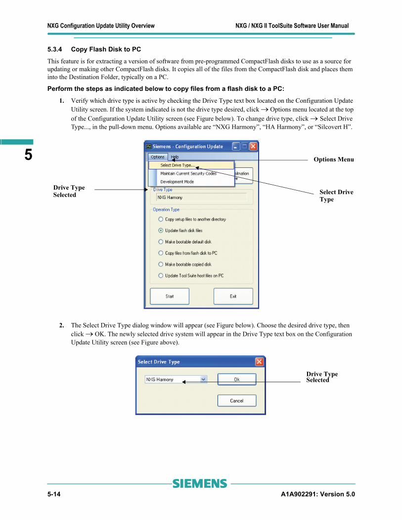
NXG Configuration Update Utility Overview NXG / NXG II ToolSuite Software User Manual
5
5.3.4 Copy Flash Disk to PC
This feature is for extracting a version of software from pre-programmed CompactFlash disks to use as a source for updating or making other CompactFlash disks. It copies all of the files from the CompactFlash disk and places them into the Destination Folder, typically on a PC.
Perform the steps as indicated below to copy files from a flash disk to a PC:
1. Verify which drive type is active by checking the Drive Type text box located on the Configuration Update Utility screen. If the system indicated is not the drive type desired, click → Options menu located at the top of the Configuration Update Utility screen (see Figure below). To change drive type, click → Select Drive Type..., in the pull-down menu. Options available are “NXG Harmony”, “HA Harmony”, or “Silcovert H”.
2. The Select Drive Type dialog window will appear (see Figure below). Choose the desired drive type, then click → OK. The newly selected drive system will appear in the Drive Type text box on the Configuration Update Utility screen (see Figure above).
Drive TypeSelected Select Drive
Type
Options Menu
Drive TypeSelected
5-14 A1A902291: Version 5.0s

NXG / NXG II ToolSuite Software User Manual NXG Configuration Update Utility Overview
5
3. After selecting drive type, go to → Configuration Update Utility screen → Operation Type, click → Copy files from flash disk to PC (see Figure below).
4. Next click → Select Source Drive button (see Figure above). The Select Source Drive screen will appear (see Figure below).
5. Select the drive letter of the CompactFlash card.
6. After choosing the Source Folder, press → Ok.
7. Return to the Configuration Update Utility screen and press → Select Destination Folder (see Figure on next page).
Select Source Drivebutton
Operation Type
Copy Files From Flash Disk
Radio ButtonTo PC
Select Source Drive ofthe CompactFlash Card
A1A902291: Version 5.0 5-15s

NXG Configuration Update Utility Overview NXG / NXG II ToolSuite Software User Manual
5
8. The Select Destination Folder screen should appear (see Figure below).
9. Select the location where Flash files are to be copied. Click → Flash Copy Folder button to manually transfer files to C:\Program Files\Robicon\Flash Copy.
10. After choosing the Destination Folder, click → Ok.
11. Next click → Start button on the Configuration Update Utility screen.
12. A dialog window will appear confirming that you are about to overwrite existing files (not shown). Click→ ‘Yes’ button.
IMPORTANT!
Ensure that the Destination Folder does not contain any files or sub-directories. Any content in the selected Destination Folder is overwritten upon clicking “Yes” as described in Step12 below.
Select Destination FolderButton
Flash Copy FolderButton
File NameSelected
5-16 A1A902291: Version 5.0s

NXG / NXG II ToolSuite Software User Manual NXG Configuration Update Utility Overview
5
13. Successful completion of process is confirmed by a pop-up message “Operation completed successfully” (see Figure below). Press → OK to finish.
A1A902291: Version 5.0 5-17s

NXG Configuration Update Utility Overview NXG / NXG II ToolSuite Software User Manual
5
5.3.5 Make Bootable Copied Disk Procedure
This feature allows the user to duplicate Flash Disks. This feature formats and makes a “Bootable” CompactFlash disk that contains all of the software and configuration files necessary to run the drive (including the system programs). The source folder can be a source that is remote or local to the PC being used. The standard source will be the Flash Copy folder. The default output drive is the CompactFlash card used in the NXG control.
Perform the steps as indicated below to make a bootable copied disk:
1. Verify which drive type is active by checking the Drive Type text box located on the Configuration Update Utility screen. If the system indicated is not the drive type desired, click → Options menu located at the top of the Configuration Update Utility screen (see Figure below). To change drive type, click → Select Drive Type..., in the pull-down menu. Options available are “NXG Harmony”, “HA Harmony”, or “Silcovert H”
2. The Select Drive Type screen will appear (see Figure below). Choose the desired drive type and then click → OK. The newly selected drive system will appear in the Drive Type text box on the Configuration Update Utility screen (see Figure above).
Note: This feature will completely reformat the entire CompactFlash and write all of the necessary files for NXG control. If the CompactFlash contains files that are to be kept, then care should be taken to back these files up before proceeding with this operation.
Select DriveType
Options Menu
Drive TypeSelected
Drive Type Selected
5-18 A1A902291: Version 5.0s

NXG / NXG II ToolSuite Software User Manual NXG Configuration Update Utility Overview
5
3. After selecting drive type, go to → Configuration Update Utility screen → Operation Type, click → Make bootable copied disk (see Figure below).
4. Next click → Select Source Folder button (see Figure above). The Select Source Folder screen will appear (see Figure below)
5. Click → Browse button to locate a newer or older version of the file name than the one currently on the CompactFlash.
6. Click → Local Hard Drive Copy button, to identify the location of the drive type selection.
7. After choosing the Source Folder, click → OK.
8. Return to the Configuration Update Utility screen and press → Select Destination Drive.
Note: For NXG drives, the file name is → C:\Program Files\Robicon\Flash Files.
Select Source DriveButton
Operation Type
Make Bootable Copied DiskRadio Button
Local HardDrive CopyButton
File Name
BrowseButton
Selected
A1A902291: Version 5.0 5-19s

NXG Configuration Update Utility Overview NXG / NXG II ToolSuite Software User Manual
5
9. The Select Source Drive screen will appear (see Figure below). Select the CompactFlash card drive.
10. After selecting the Destination Drive, click → Ok.
11. Next click → Start button on the Configuration Update Utility screen.
12. A dialog window will appear confirming that you are about to overwrite existing files (not shown). Click→ ‘Yes’ button.
Note: The files will be copied to the CompactFlash disk. A screen will be displayed indicating System is processing (see Figure below).
Select Destination DriveButton
Select Destination Driveof theCompactFlash Card
5-20 A1A902291: Version 5.0s

NXG / NXG II ToolSuite Software User Manual NXG Configuration Update Utility Overview
5
13. Upon successful completion of process a screen will appear (not shown) asking if user wishes to eject the Flash Disk. Click → Yes.
14. A dialog window will appear confirming that you are about to overwrite existing files (not shown). Click→ ‘Yes’ button.
15. Successful completion of process is confirmed by a pop-up message “Operation completed successfully” (see Figure below). Press → OK to finish.
16. User can now insert the CompactFlash disk into the CPU board.
A1A902291: Version 5.0 5-21s

NXG Configuration Update Utility Overview NXG / NXG II ToolSuite Software User Manual
5
5.3.6 Update ToolSuite Host Files on PC
This feature updates the configuration files for all ToolSuite configured drives. The ToolSuite installation program updates configuration files automatically. As an option this section is provided for Siemens personnel, who wish to manually update ToolSuite configuration files.
Perform the steps as indicated below to update ToolSuite Host Files on PC:
1. Verify which drive type is active by checking the Drive Type text box located on the Configuration Update Utility screen. If the system indicated is not the drive type desired, click → Options menu located at the top of the Configuration Update Utility screen (see Figure below). To change drive type, click → Select Drive Type..., in the pull-down menu. Options available are “NXG Harmony”, “HA Harmony”, or “Silcovert H”.
2. The Select Drive Type screen will appear (see Figure below). Choose the desired drive type and then click → OK. The newly selected drive system will appear in the Drive Type text box on the Configuration Update Utility screen (see Figure above).
Select DriveType
Options Menu
Drive TypeSelectedSelected
Drive TypeSelected
5-22 A1A902291: Version 5.0s

NXG / NXG II ToolSuite Software User Manual NXG Configuration Update Utility Overview
5
3. After selecting drive type, go to → Configuration Update Utility screen → Operation Type, click → Update ToolSuite host files on PC (see Figure below).
4. Next click → Select Source Folder button (see Figure above). The Select Source Folder screen will appear (see Figure below).
5. Click → Browse button to locate source folder. Ensure that the source files are match selected Drive Type.
6. Next click → Start button on the Configuration Update Utility screen.
7. A dialog window will appear confirming that you are about to overwrite existing files (not shown). Click→ ‘Yes’ button.
8. Successful completion of process is confirmed by a pop-up message “Operation completed successfully” (see Figure on next page). Press → OK to finish.
Note: For NXG drives, the file name is → C:\Program Files\Robicon\Flash Files.
Select Source FolderButton
Operation Type
Radio ButtonMake Bootable Copied Disk
Local HardDrive CopyButton
File Name Selected
BrowseButton
A1A902291: Version 5.0 5-23s

NXG Configuration Update Utility Overview NXG / NXG II ToolSuite Software User Manual
5
∇ ∇ ∇5-24 A1A902291: Version 5.0s

NXG / NXG II ToolSuite Software User Manual Drive Server Setup/Status Utility
6
The Drive Server Setup/Status utility defines the setup requirements for computer-to-computer communication, where one of the computers is hosting a Drive Server. Refer to the Drive Server Manual for information related to configuration of a system hosting a Drive Server.
6.1 Starting and Configuring the Configuration Update UtilitySelect → Utilities tab of the ToolSuite application and click → Drive Server Setup/Status button (as shown in Figure below):
If no existing drive server is configured, the first time the Drive Server is started the Drive Server Setup/Status screen will appear as shown below:
To begin using the Driver Server Utility, a new server connection must be established. Refer to section 6.1.1 of this manual.
CHAPTER
6 Drive Server Setup/Status Utility
Note: This utility is intended for use by trained Siemens personnel only.
Note: This utility is used both on computers that host a Drive Server and also with computers that communicate to another computer hosting a Drive Server.
ButtonConfiguration Update
Error Message
A1A902291: Version 5.0 6-1s

Drive Server Setup/Status Utility NXG / NXG II ToolSuite Software User Manual
6
6.1.1 Create a New Server Connection
This feature allows the user to create a new server connection. If an error message displays on the Drive Server Setup/Status Utility screen, a new server connection must be created.
Perform the steps as indicated below to create a new server connection:
1. On the Drive Server Setup/Status Utility screen click → Security menu, select → Enter Security code (see Figure below).
2. The Security Code screen will appear (see Figure below). Enter → drsv in the text box, then click → Ok.
3. The Valid Code screen will appear confirming correct security code was entered (see Figure below). Click → Ok, then proceed to next step.
4. Return to the Drive Server Setup/Status Utility screen and click → Setup menu → click Server Connection Maintenance, next select → Create New Server Connection, then click (see Figure on following page).
SecurityMenu Enter Security
Code
Enter ‘drsv’ in Text Box
6-2 A1A902291: Version 5.0s
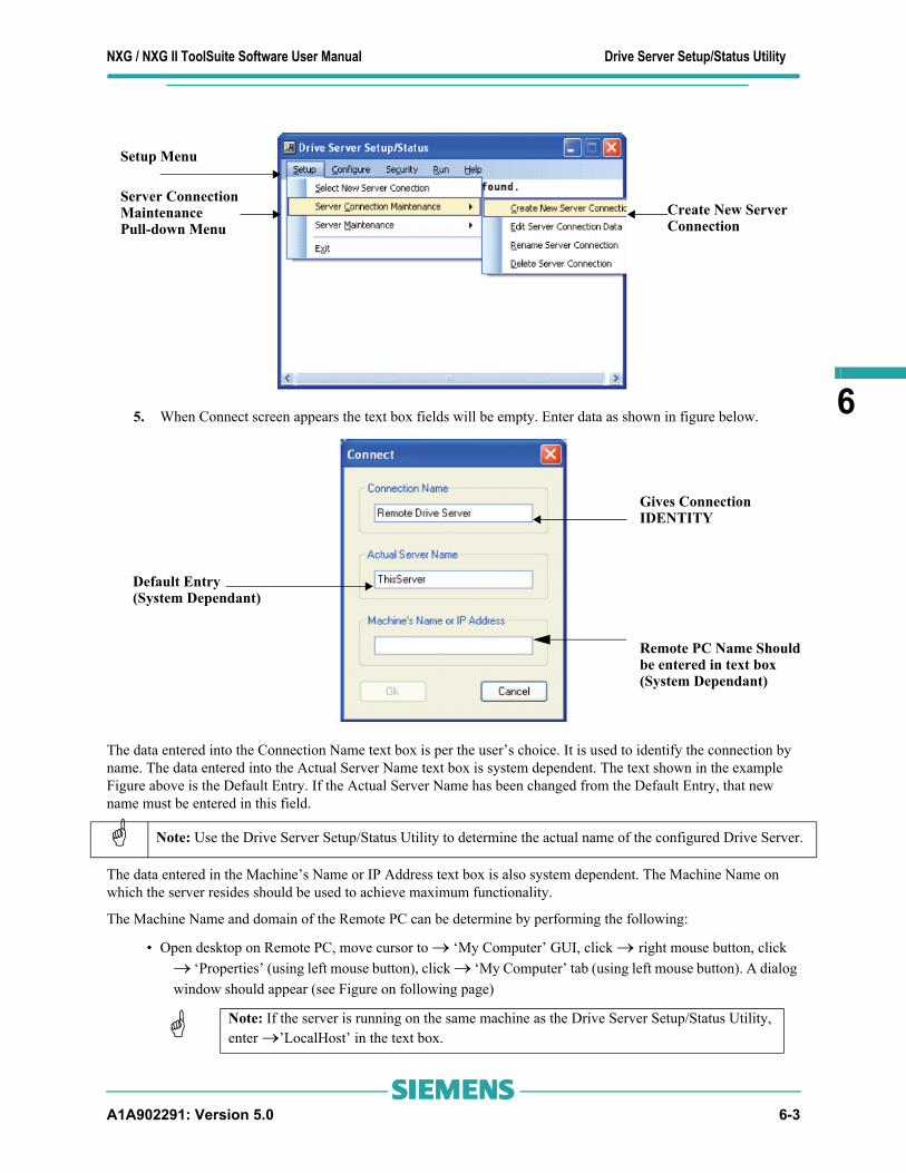
NXG / NXG II ToolSuite Software User Manual Drive Server Setup/Status Utility
6
5. When Connect screen appears the text box fields will be empty. Enter data as shown in figure below.The data entered into the Connection Name text box is per the user’s choice. It is used to identify the connection by name. The data entered into the Actual Server Name text box is system dependent. The text shown in the example Figure above is the Default Entry. If the Actual Server Name has been changed from the Default Entry, that new name must be entered in this field.
The data entered in the Machine’s Name or IP Address text box is also system dependent. The Machine Name on which the server resides should be used to achieve maximum functionality.
The Machine Name and domain of the Remote PC can be determine by performing the following:
• Open desktop on Remote PC, move cursor to → ‘My Computer’ GUI, click → right mouse button, click → ‘Properties’ (using left mouse button), click → ‘My Computer’ tab (using left mouse button). A dialog window should appear (see Figure on following page)
Note: Use the Drive Server Setup/Status Utility to determine the actual name of the configured Drive Server.
Note: If the server is running on the same machine as the Drive Server Setup/Status Utility, enter →’LocalHost’ in the text box.
Setup Menu
Server ConnectionMaintenancePull-down Menu
Create New ServerConnection
Gives Connection IDENTITY
Default Entry(System Dependant)
Remote PC Name Shouldbe entered in text box(System Dependant)
A1A902291: Version 5.0 6-3s

Drive Server Setup/Status Utility NXG / NXG II ToolSuite Software User Manual
6
The Machine Name has two benefits. First, it provides additional functionality through the Drive Server Setup/Status application. Secondly, the Machine Name does not require the PC that the Drive Server is executing from to have a static IP address.
Sometimes site specific network policies prohibit the PC which hosts the Drive Server and the remote PC from being on the same domain. In this case the IP address of the PC which hosts the Drive Server should be entered into the Machine Name or IP Address of the Connect screen.
After all of the previous steps have been completed, the Drive Server Setup/Status Utility screen should now display the following data:
Note: The best setup is achieved when both PCs are located in the same domain.
Note: A static IP Address must be entered so that the IP Address of the machine will remain constant.
Actual Computer Name ofRemote PCRemote PC Domain
Computer Name Tab
6-4 A1A902291: Version 5.0s

NXG / NXG II ToolSuite Software User Manual Drive Server Setup/Status Utility
6
6.2 Setup / Status Application OperationFeatures Overview
The Drive Server Setup/Status Utility screen features currently found are:
• Status Screen
• Menu Functions
6.2.1 Status Screen
The Status screen indicates the following system data:
• Server Name: Refers to the name of the Drive Server connected to the PC. Listed below are the variables found in this operation:
o Is server ok to operate: Indicates if Drive Server has/has not been successfully configured. If indication is ‘False’, refer to Drive Server’s event log to diagnose and fix error
o Is server connected to drives: This statement is ‘TRUE’ when: Drive Server is ready to operate, when Drive Server is connected to the minimum number of drives required for operation, and is connected to the Master Unit (HA Drive Systems)
o Is server configured: Confirms Drive Server has/ has not been properly configured and is/is not operational. (refer to ‘Set Server as Configured’- Section 6.2.2.3.2)
o Is System duplicate type: ‘Yes’ indicates duplicate type systems (HA Drive Systems). No is indicated with Parallel Drive Systems. (refer to ‘Set Operating Conditions’ - Section 6.2.2.3.3)
o The controlling unit is: Indicates the current controlling unit (HA Drive Systems - Only)
o The number of units in cluster: This line item identifies the total number of Drives in system (refer to ‘Set Operating Conditions’ - Section 6.2.2.3.3)
o The number of units connected: The collective number of Drives communicating together
o Number of units to operate: This number represents the minimum number of Drives required to be connected in order for the system to run a motor (refer to ‘Set Operating Conditions’ - Section 6.2.2.3.3)
o Unit connect status: This line item provides the connection status of each Drive defined in the system
A1A902291: Version 5.0 6-5s

Drive Server Setup/Status Utility NXG / NXG II ToolSuite Software User Manual
6
6.2.2 Menu Functions
6.2.2.1 Setup Menu
6.2.2.1.1 Select New Server Connection
This section allows the user to switch between Drive Server connections.
6.2.2.1.2 Server Connection Maintenance
This item is not enabled within the menus, unless a security password has been entered to grant ‘Restricted Access’. Without Restricted Access permissive, NO sub-menu items will be available.
6.2.2.1.3 Create New Server Connection
This menu item allows user to create a new Drive Server connection. To perform this operation, three variables must be entered into the text boxes on the Connect screen. First, the data entered into the Connection Name text box is per the user’s choice. It is used to identify the connection by name. Second, the data entered into the Actual Server Name text box is system dependent. The text must be the actual name used in the server definition..
Third, the data entered in the Machine’s Name or IP Address text box is also system dependent. The Machine Name on which the server resides should be used to achieve maximum functionality.
The Machine Name and domain of the Remote PC can be determine by performing the following:
•Open desktop on Remote PC, move cursor to → ‘My Computer’ GUI, click → right mouse button, click → ‘Properties’ (using left mouse button), click → ‘My Computer’ tab (using left mouse button). A dialog window should appear (see Figure on following page)
6.2.2.1.4 Edit Server Connection Data
This selection allows the user to edit the server information for a connection. This selection is valid only if there is a minimum of one connection defined. If two or more connections are defined, the user will be asked which connection will be desired for editing.
Note: If there are < 2 server connections defined, one of the following informational messages will be displayed on the Drive Server Setup/ Status Utility screen:
• There are no choices
• No alternative choices are available
Note: If the Actual Server Name has been changed from the Default Entry, that new name must be entered in this field.
Note: If the server is running on the same machine as the Drive Server Setup/Status Utility, enter →’LocalHost’ in the text box.
Note: If the Drive Server is executing from a different domain, the Machine Name cannot be used. For this application the IP Address of the machine on which the server is executing should be entered. That machine should be setup with a static IP address.
Note: Refer to ‘Create New Server Connection’ (Section 6.2.2.1.3) to identify what data to enter in the Connect screen, Actual Server Name, and Machine Name/IP Address text boxes.
Note: If data for the current connection being used has been edited, the Drive Server Setup/Status Utility will reconnect using the new information.
6-6 A1A902291: Version 5.0s

NXG / NXG II ToolSuite Software User Manual Drive Server Setup/Status Utility
6
6.2.2.1.5 Rename Server Connection
This menu item allows the user to rename the server connection. This selection is valid only if there is a minimum of one connection defined. If two or more connections are defined, the user will be asked which connection will be desired for renaming.
6.2.2.1.6 Delete Server Connection
This selection allows the user to delete a server connection. This selection is only valid if there are a minimum of (2) connections defined.
6.2.2.2 Server Maintenance
6.2.2.2.1 List Server Names
Clicking on this menu item provides the user with a list of the currently defined server names on the user’s PC.
6.2.2.2.2 Create New Server
Selecting this item allows the user to create a new server. Drive Servers can only be created on the machine on which the Drive Server Setup/Status Utility is currently running. To create a new server, first enter the new server’s name.
After entering name for new server, the user must now define the new server’s operating parameters.
Next enter the IP Addresses for each of the attached drives.
6.2.2.2.3 Rename Server
Selecting this item will allow the user to rename a server. Drive Servers can only be renamed on the machine on which the Drive Server Setup/Status utility is currently running. If there is more than one server defined the user will be asked to select the server to be renamed.
After completing this step all connections using the old server name must be updated with the new server name.
Note: After completing this process, the connection name for any drive using the old connection name must be updated with the new name.
Note: The server connection being used cannot be deleted.
Note: If the name chosen already exists for another server, the user must select a different name.
Note: See ‘Set Operating Conditions’ - Section 6.2.2.3.3
Note: The server will be stopped and then restarted during this process.
IMPORTANT! The new server is not enabled within the menus if restricted access has not been established by entering the security password or there is no server installed on the user’s PC.
Note: The server will be stopped and then restarted during this process.
A1A902291: Version 5.0 6-7s

Drive Server Setup/Status Utility NXG / NXG II ToolSuite Software User Manual
6
6.2.2.2.4 Delete Server
Choosing this feature allows the user to delete a server. Drive Servers can only be deleted on the machine on which the Drive Server Setup/ Status Utility is currently running. There must be a minimum of one server defined on a PC running the server software.
6.2.2.3 Config Menu
6.2.2.3.1 Select Server Controlled Data
This menu item allows the user to set the parameters that will be controlled by the server. The user must be connected to a Drive Server for this menu item to function. The controlled data set must be enabled for the server that is connected.
When this item is selected, a list of parameter IDs will be displayed with checkboxes. The user will identify the parameters to be controlled by the server, by clicking the associated checkboxes beside each of parameter. Only those parameters checked will be controlled by the server.
Once a parameter is configured to be controlled by a server, the same value will be maintained in all attached drives.
6.2.2.3.2 Set Server as Configured
A Drive Server that is operating has been configured. Therefore a server that is being setup for operation is unconfigured. An unconfigured server communicates with server, but parameter control has not been enabled and drive tool communication with the drives through the server is not permitted. A Drive Server must be set as unconfigured to use the select server controlled data, set operating conditions, configure initial parameters or change drive Names/IP Address menu items. The user must be connected to a server to perform this operation.
IMPORTANT! The new server is not enabled within the menus if restricted access has not been established by entering the security password or there is no server installed on the user’s PC.
Note: If only one server is defined on the PC, the user will not be allowed to delete it.
Note: The server will be stopped and then restarted during this process.
IMPORTANT! The new server is not enabled within the menus if restricted access has not been established by entering the security password or there is no server installed on the user’s PC.
Note: There are menu items provided to alternately check or uncheck all of the checkboxes.
IMPORTANT! The item is not enabled within the menus if restricted access has not been established by entering the security password or there is no server installed on the user’s PC.
Note: See ‘Set Server as Configured’ - Section 6.2.2.3.2
IMPORTANT! The item is not enabled within the menus if restricted access has not been established by entering the security password or there is not connected to server.
6-8 A1A902291: Version 5.0s

NXG / NXG II ToolSuite Software User Manual Drive Server Setup/Status Utility
6
6.2.2.3.3 Set Operating Conditions
This menu item is for future functionality and is currently not available.
6.2.2.3.4 Configure Initial Parameters
This option applies only to Non-High Availability type systems. The menu item gives the user the ability to configure the initial parameters for the server. This procedure is used for first-time set up of server parameters or to restore parameter settings that may have been altered due to an interruption with server. The user must be connected to a server to perform these commands.
This section of this chapter addresses loading server with proper parameter values prior to being set as Configured.
When a parameter value mismatch occurs a dialog window will be displayed. In the first column of the display the user will see a list of the Parameter IDs (Only Parameter IDs which are set as server controlled in the respective server controlled data procedure will be displayed). In the second column of the display the user will see a list of values currently in the server. The next column will display lists of data for each of the drives connected to the server.
If a parameter value conflict is identified, the user must resolve the error before proceeding. If one of the drives has the correct value the user must check the box next to the displayed value in that drive’s respective column (Only one column per row may contain a check mark). By double clicking on a column header, the user will be able to check all of the checkboxes in that column. Click → Apply button to move the data from the checked items into the server, then view results. Press → Refresh button to refresh the data from the drives. Some of the drives data may be listed as “Unknown”. This occurs when the server contains controllable parameters which are not used in the attached drive.
6.2.2.3.5 Change Drive Names/IP Addresses
This menu item allows the user to se the IP addresses for each of the drives that are linked to the server. The user must be connected to a server to perform this operation (the server used for this operation will have its IP Address changed).
There should be (1) IP Address entry box for each drive identified in the set operating conditions ‘Number of Drives’ field. The number of drives SHOULD be set prior to entering data.
IMPORTANT! The server chosen must have initial parameters configured.
Note: Once the server is set as ‘Configured’ any parameter value in a drive that does not agree with the server’s value, will be over written to match the value of the server.
Note: Rows will be highlighted in Yellow for any drive having a parameter value that is different than the server’s value.
IMPORTANT! The item is not enabled within the menus if restricted access has not been established by entering the security password, the system is a High Availability type system, if there is no server connected or connected server is set As Configured (see ‘Set Server as Configured’ - Section 6.2.2.3.2).
Note: For High Availability systems the first address must be reserved for the “A” control unit (this unit does not control the fiber optic switch).
IMPORTANT! This item is not enabled within the menus if restricted access has not been established by entering the security password or the connected server is set As Configured (see ‘Set Server as Configured’ - Section 6.2.2.3.2).
A1A902291: Version 5.0 6-9s

Drive Server Setup/Status Utility NXG / NXG II ToolSuite Software User Manual
6
6.2.2.4 Security Menu
6.2.2.4.1 Enter Security Code
Selecting this menu item displays a dialog window containing a text box to enter a password. The password allows the user to access restricted features within the program.
6.2.2.4.2 Security Clear
6.2.2.4.3 Run Menu
6.2.2.4.4 Start Menu
Clicking this menu command will start server.
Clicking this menu command will stop server.
6.2.2.4.5 Restart Menu
Clicking this menu command will stop, then restart the server. This feature allows user to reinitialize server if server’s drive information has been modified.
∇ ∇ ∇
IMPORTANT! This item is not enabled within the menus if restricted access HAS BEEN GRANTED by entering the security password.
CAUTION! When enabling this menu option the user’s access to the restricted features within a program WILL BE REMOVED.
IMPORTANT! This item is not enabled within the menus if restricted access HAS NOT been granted by entering the security password.
Note: This menu item is not available if an IP Address is entered in the server connection data in place of a machine name (See ‘Create New Server Connection’- Section 6.2.2.1.3).
IMPORTANT! This menu item is not enabled if restricted access HAS NOT been granted by entering the security password, no server is connected to, or the server is currently running.
IMPORTANT! This menu item is not enabled if restricted access HAS NOT been granted by entering the security password, no server is connected to, or the server is currently NOT running.
IMPORTANT! This menu item is not enabled if restricted access HAS NOT been granted by entering the security password, no server is connected to, or the server is currently NOT running.
6-10 A1A902291: Version 5.0s

NXG / NXG II ToolSuite Software User Manual High Availability Drive Tool
7
This section defines the features added to the Drive Tool, exclusive to High Availability systems only.
7.1 Connection to Drive ToolAfter defining the Drive Server connection on a PC (as outline in Section 6.1 of this manual), that connection can be used for communication by the Drive Tool.
In order for a drive to connect through it’s Drive Server, the Drive Server must first be set “As Configured” and must have “Ok to operate” and “Connected to drives” as its status. If these conditions are not met, the Drive Tool will not connect.
1. Create a new Drive Tool configuration (as outlined in the ToolSuite Manual). After creating new Drive. After creating new Drive Tool, start the new instance. A window similar to the one in the Figure below will appear.
2. Double click the “TCP/IP server name” parameter in the menu tree. A dialog window will appear. In the ‘New Value’ text box, enter the name of the Drive Server connection (“Remote Drive Server” is used in the Figure on the next page).
CHAPTER
7 High Availability Drive Tool
Note: It is important to remember the server connection name being used on a PC, as this name must also be used to connect the drive with the Drive Tool from that PC.
A1A902291: Version 5.0 7-1s

High Availability Drive Tool NXG / NXG II ToolSuite Software User Manual
7
..
Note: If the Name entered is not recognized by the Drive Server, the following dialog will appear.
Note: If the Name entered is accepted by the Drive Server, the following dialog will appear.
7-2 A1A902291: Version 5.0s

NXG / NXG II ToolSuite Software User Manual High Availability Drive Tool
7
7.2 Selecting Desired Control SystemTo change the selected Control System perform the following steps:
1. Click on → View menu, then click → Drive in the pull-down menu (as shown in Figure below).
2. Type ‘Control’ in the text box of the dialog window (see Figure below).
A1A902291: Version 5.0 7-3s

High Availability Drive Tool NXG / NXG II ToolSuite Software User Manual
7
When the ‘Control’ feature is selected on the Drive Tool menu tree, only the parameters which are server controlled will be active. The controlling unit, either ‘A’ or ‘B’ will be identified in the list. When a selection is made for a specific Control System, the parameters in the tree will be those parameters on that control which are not server controlled. The Control System that is active will be displayed in the top line of the menu tree.
∇ ∇ ∇
Note: ‘Control’ is the default setting and represents the Control System currently controlling the motor.
7-4 A1A902291: Version 5.0s

NXG / NXG II ToolSuite Software User Manual Operators and Precedence
A
A.1 Operators and PrecedenceThere are two forms of operators that can be used in a source line of the system program. These forms are unary operators (requiring only a single operand) and binary operators.
There is a single unary operator: the negate operator. This operator takes the form of a slash character (“/”) which precedes a single input symbol. This operator forms the inverse logic equivalent of the symbol immediately following it for incorporation into the statement evaluation. It has higher precedence than the binary operators, which means it is evaluated before the evaluation of any binary operations.
For example, the expression:
/Zero_O
equates to:
NOT Zero_O.
If the input variable “Zero_O” were FALSE, then “/Zero_O” would equate to TRUE.
There are two binary operators: AND and OR. These operators take the form of an asterisk (“*”) and a plus sign (“+”), respectively. These operators correspond to the Boolean AND and OR functions. Unlike the unary NOT operator (which requires only a single variable), each of these operators requires two variables, which surround the operator.
The binary operators “+” and “*” serve to form the simple Boolean combination of the combined expression preceding the operator and the symbol (possibly negated) immediately following the operator. Parentheses are not allowed to force expression evaluation. The expression must be formed with left to right precedence and must be expanded to simple form.
Refer to the Boolean truth tables in Table A-1 for functional descriptions of the operators.
Table A-1 shows the precedence of operations. Table A-2 shows syntax examples.
Table A-1: Boolean Truth Table for the NOT, AND and OR Functions
APPENDIX
A Operators and Precedence
Note: The “/” symbol must be followed by an input symbol.
NOT Function AND Function OR Function
A /A A B A*B A B A+B
False True False False False False False False
True False False True False False True True
True False False True False True
True True True True True True
A1A902291: Version 5.0 A-1s

Operators and Precedence NXG / NXG II ToolSuite Software User Manual
A
Table A-1Precedence of OperationsTable A-2Syntax Examples
The term “sum-of-products” comes from the application of Boolean algebraic rules to produce a set of terms or conditions that are grouped in a fashion that represents parallel paths (ORing) of required conditions that all must be met (ANDing). This would be equivalent to branches of connected contacts on a relay logic ladder that connect to a common relay coil. In fact, the notation can be used as a shortcut to describe the ladder logic.
First let us examine the rules of Boolean algebra. The set of rules that apply in this logical math are broken into three sets of laws: commutative, associative, and distributive. The operators are “AND” (abbreviated with the “·” character [or “*” character from the keyboard]), “OR” (abbreviated with the “+” character), and “NOT” (abbreviated with a line above the operand, e.g., A [or a preceding “/” character from the keyboard]). The commutative, associative, and distributive rules are shown in Table A-3.
Table A-3Boolean Laws
Type of Operation Symbol Meaning Precedence
Unary Operation / Not High (performed first)
Binary Operation * And :
Binary Operation + Or Low (performed last)
Example Description
C = A + B; Correct, C equals A OR B
C = A * B + D; Correct, C equals (A AND B) OR D
C = A + B * D; Correct, C equals A OR (B AND D)
C = A * B + A * D; Correct, C equals (A AND B) OR (A AND D)
C = A * (B + D); Incorrect, parentheses not allowed
C = A + /B; Correct, C equals A OR (NOT B)
/C = A * B; Incorrect, negation not permitted on output side
Commutative1
1. The syntax “AB” implies (A · B)
Associative1 Distributive1
A + B = B + A A + (B + C) = (A + B) + C A (B + C) = AB + AC
AB = BA A (BC) = (AB) C
A-2 A1A902291: Version 5.0s

NXG / NXG II ToolSuite Software User Manual Operators and Precedence
A
Table A-4General Rules of Boolean MathAdd to this DeMorgan's Theorem which states “the complement of the intersection (AND) of any number of sets equals the union (OR) of their complements” which, simply stated, means that if you invert a grouping of elements, you invert the individual elements and also change the logical relationship between them. So you can change from an OR to an AND function, for example:
(A + B) = (A · B)
or from an AND to an OR function, for example:
(A · B) = (A + B)
By using these rules, any logical statement can be reduced to the sum (+) of products (·) or the ORing of ANDed terms as illustrated in the following example:
O = AB + BCD + CDF;
The SOP file, as mentioned above, is written with a text editor or a word processor set for pure ASCII text (having a .TXT file extension) with no control or formatting codes with the exception of horizontal tabs (ASCII code 09h) and carriage returns (0Dh). Only printable characters and spaces (20h) can be used. The file consists of the following format:
General Rules General Rules General Rules1
1. The syntax “AB” implies (A · B)
A · 0 = 0 A + 0 = A A + AB = A
A · 1 = A A + 1 = 1 A (A + B) = A
A · A = A A + A = A (A + B) (A + C) = A + BC
A · A = 0 A + A = 1 A + AB = A + B
= A = A
Item Description
Drive type specifier This must reside on the first line of the file prefixed with the pound sign (#) and followed with the name of the drive (in the case of Perfect Harmony, this would be #Harmony;)
A1A902291: Version 5.0 A-3s

Operators and Precedence NXG / NXG II ToolSuite Software User Manual
A
A.2 Ladder Logic TranslationIt was mentioned above that the sum-of-products notation can represent ladder logic. In actuality, it is very easy to directly translate between the two. For example, consider the equation or statement:
Z = ABC + DEF + FGH;
Translated into the notation of the limited ASCII characters available in a common text editor, the statement would read as follows (note that the components are separated at “ORs” and stacked for clarity).
Z =/A*B*C + D*/E*F + F*G*H;
This statement can be pictorially represented by breaking each statement down in the following manner:
1. First, the output variable (in this case Z) is represented by a coil to the right of the ladder.
2. Second, each product term (the variables separated by the asterisk) is represented by a single line of contacts connecting to the coil.
3. All the product terms that are summed (separated by the plus sign) are represented by parallel paths to the same coil.
Header A comment field containing the following information:
Title - Siemens LD A Perfect Harmony drive
Program part number
Customer name
Sales order number and Siemens drive part number
Drive description Original SOP date
File name
Engineer Name (Originator)
Revision history (date and change description)
Note: A comment is any text within the file, preceded by a semi-colon, which is used exclusively for informational purposes and is ignored by the compiler.
Operators Comment field containing operators and symbols
I/O specifier Comment field describing the system input and output flags as they relate to the external system. This would include any user faults and notes on menu settings, such as Comparator setups and XCL settings, as they apply to the system program (more on this later). These can (and should) be grouped logically to allow easy access to information and to make the SOP more understandable.
User fault messages Assigns the text to be displayed when this particular user fault is activated.
Main logic section All the equations and assignments for the configuration, annunciation, and operation of the drive. These should be logically arranged with careful consideration given to the order of evaluation of the equations.
Item Description
A-4 A1A902291: Version 5.0s

NXG / NXG II ToolSuite Software User Manual Operators and Precedence
A
4. All non-inverted contacts are represented by normally open (NO) contacts, while the inverted terms arerepresented by normally closed (NC) contacts.
The resulting ladder logic is illustrated in Figure A-1.
Figure A-1: Ladder Logic Representation of a Boolean Expression - Example 1
Conversely, if the ladder logic shown in Figure A-1 is desired, it could be converted into a sum-of-products statement. The procedure would be the inverse of the previous, and is enumerated below.
1. First place the label of the output relay coil to the left, with an equals sign following.
2. Next, start in each path from left to the connection to the coil on the right, writing the label for each contact with the asterisk representing the AND or product operator in between.
3. In front of each NC contact, place a forward slash representing the inversion or NOT operator (shown in the equations as a bar over the variable name).
4. Repeat this for each parallel path using the OR (sum) operator (+) in between each grouping of product terms.
5. Finally, the statement is terminated by a semicolon to represent the end of the statement.
Figure A-1Ladder Logic Representation of a Boolean Expression - Example 2
∇ ∇ ∇
A1A902291: Version 5.0 A-5s

Operators and Precedence NXG / NXG II ToolSuite Software User Manual
A
A-6 A1A902291: Version 5.0s

NXG / NXG II ToolSuite Software User Manual Ethernet Connections
B
B.1 Direct ConnectionThe direct connection is for either a single PC connected to the drive using a special Ethernet crossover cable, or a small network hub or switch connecting multiple drives to one or more PCs.B.1.1 Required Items for a Single Ethernet Direct Connection
• Crossover patch cable: this allows you to connect directly with the drive without a hub or server (requires a coupler, as shown below):
Solutions4sure, http://www.solutions4sure.com/, 800.595.9333, supplier no. SOL4
S878311 10/100 BT CAT5 XOVER PATCH 3’ ORG 88468
S104652 RJ45 MODULAR COUPLER STRT R6G050
B.1.2 Required Items for a Single PC Multiple Drive Ethernet Connection Support
• EtherFast 10/100 5 port HUB
GLOBAL COMPUTER SUPPLIES, http://www.globalcomputer.com/eQZ25aqd/, 888.8GL.OBAL
302517 Linksys EtherFast 10/100 5pt WKGP Hub EFAH05W
• Ethernet Cat5 Cable
GLOBAL COMPUTER SUPPLIES, http://www.globalcomputer.com/eQZ25aqd/, 888.8GL.OBAL
ZCC31805XX 25’ SNAG-PROOF Ethernet cable Cat5 RJ-45 (xx - choose color)
APPENDIX
B Ethernet Connections
Note: This configuration also allows for more than one PC.
Tool Suite PC
NXG Drive
Control
Crossover cable and coupler
ToolSuite PC
HUBor
Switch
NXGDrive
Control
NXGDrive
Control
A1A902291: Version 5.0 B-1s

Ethernet Connections NXG / NXG II ToolSuite Software User Manual
B
B.1.3 Configuring a PC to Work with a Direct Connection
B.1.3.1 Windows® XP /2000
1. From the Start Menu, select “Settings” and click “Control Panel” as shown below
Note: Windows® NT/XP/2000 and Windows® Vista each have different procedures for the configuration of network parameters.
Control Panel
B-2 A1A902291: Version 5.0s

NXG / NXG II ToolSuite Software User Manual Ethernet Connections
B
2. Within the Control Panel, double click on the “Network and Internet Connections” icon.
Double Click
A1A902291: Version 5.0 B-3s

Ethernet Connections NXG / NXG II ToolSuite Software User Manual
B
3. Select “Network Connections”
4. The Network Connections dialog window displays. Highlight “Local Area Connection” and right-click after to display a pop-up window containing a list of parameters. Select “Properties” to display the “Local Area Connections Properties” window.
Select Network Connections Icon
SELECTPROPERTIES
B-4 A1A902291: Version 5.0s

NXG / NXG II ToolSuite Software User Manual Ethernet Connections
B
5. From the “Local Area Connection Properties” window select the “Internet Protocol TCP/IP ->” connection that your PC uses (there may be more than one).
6. Choose the “Use the following IP address” radio button.
A1A902291: Version 5.0 B-5s
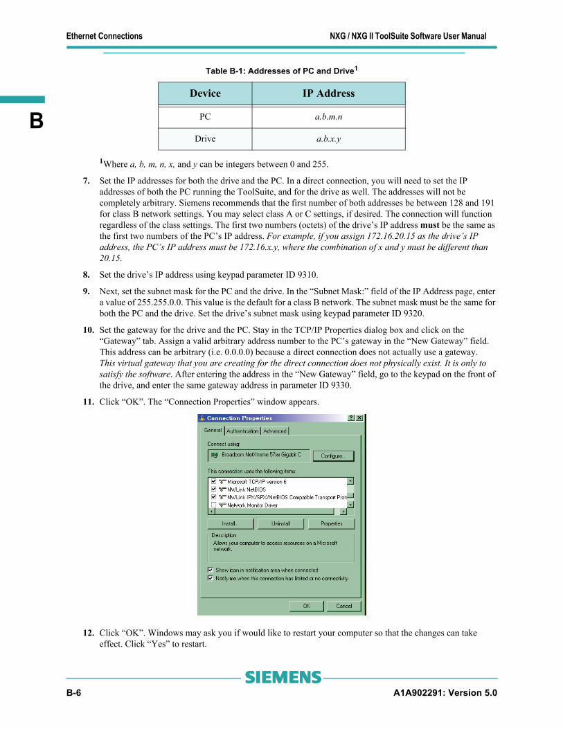
Ethernet Connections NXG / NXG II ToolSuite Software User Manual
B
Table B-1: Addresses of PC and Drive1
1Where a, b, m, n, x, and y can be integers between 0 and 255.
7. Set the IP addresses for both the drive and the PC. In a direct connection, you will need to set the IP addresses of both the PC running the ToolSuite, and for the drive as well. The addresses will not be completely arbitrary. Siemens recommends that the first number of both addresses be between 128 and 191 for class B network settings. You may select class A or C settings, if desired. The connection will function regardless of the class settings. The first two numbers (octets) of the drive’s IP address must be the same as the first two numbers of the PC’s IP address. For example, if you assign 172.16.20.15 as the drive’s IP address, the PC’s IP address must be 172.16.x.y, where the combination of x and y must be different than 20.15.
8. Set the drive’s IP address using keypad parameter ID 9310.
9. Next, set the subnet mask for the PC and the drive. In the “Subnet Mask:” field of the IP Address page, enter a value of 255.255.0.0. This value is the default for a class B network. The subnet mask must be the same for both the PC and the drive. Set the drive’s subnet mask using keypad parameter ID 9320.
10. Set the gateway for the drive and the PC. Stay in the TCP/IP Properties dialog box and click on the “Gateway” tab. Assign a valid arbitrary address number to the PC’s gateway in the “New Gateway” field. This address can be arbitrary (i.e. 0.0.0.0) because a direct connection does not actually use a gateway. This virtual gateway that you are creating for the direct connection does not physically exist. It is only to satisfy the software. After entering the address in the “New Gateway” field, go to the keypad on the front of the drive, and enter the same gateway address in parameter ID 9330.
11. Click “OK”. The “Connection Properties” window appears.
12. Click “OK”. Windows may ask you if would like to restart your computer so that the changes can take effect. Click “Yes” to restart.
Device IP Address
PC a.b.m.n
Drive a.b.x.y
B-6 A1A902291: Version 5.0s

NXG / NXG II ToolSuite Software User Manual Ethernet Connections
B
B.1.3.2 Windows® Vista
1. From the Start Menu, select “Network” and click “Open” to display the available network connections.
2. Click the “Local Area Connection” button to display the “Local Area Connections Properties” dialog window. From this window select Internet Protocol Version 4 (TCP/IPv4) to display its dialog box.
A1A902291: Version 5.0 B-7s

Ethernet Connections NXG / NXG II ToolSuite Software User Manual
B
3. Select the “Use the following IP address” radio button.
Table B-1: Addresses of PC and Drive1
1Where a, b, m, n, x, and y can be integers between 0 and 255.
4. Set the IP addresses for both the drive and the PC. In a direct connection, you will need to set the IP addresses of both the PC running the ToolSuite, and for the drive as well. The addresses will not be completely arbitrary. Siemens recommends that the first number of both addresses be between 128 and 191 for class B network settings. You may select class A or C settings, if desired. The connection will function regardless of the class settings. The first two numbers (octets) of the drive’s IP address must be the same as the first two numbers of the PC’s IP address. For example, if you assign 172.16.20.15 as the drive’s IP address, the PC’s IP address must be 172.16.x.y, where the combination of x and y must be different than 20.15.
5. Set the drive’s IP address using keypad parameter ID 9310.
6. Next, set the subnet mask for the PC and the drive. In the “Subnet Mask:” field of the IP Address page, enter a value of 255.255.0.0. This value is the default for a class B network. The subnet mask must be the same for both the PC and the drive. Set the drive’s subnet mask using keypad parameter ID 9320.
7. Set the gateway for the drive and the PC. Assign a valid arbitrary address number to the PC’s gateway in the “Default gateway:” field. This address can be arbitrary (i.e. 0.0.0.0) because a direct connection does not actually use a gateway. This virtual gateway that you are creating for the direct connection does not physically exist. It is only to satisfy the software. After entering gateway address here, go to the keypad on the front of the drive, and enter the same gateway address in parameter ID 9330. Click “OK”.
8. Click “OK” on the next window’s dialog box. Windows may ask you if would like to restart your computer so that the changes can take effect. Click “Yes” to restart.
∇ ∇ ∇
Device IP Address
PC a.b.m.n
Drive a.b.x.y
B-8 A1A902291: Version 5.0s

NXG / NXG II ToolSuite Software User Manual Glossary
C
This appendix contains definitions of terms and abbreviations used throughout the Perfect Harmony series manuals.AND - AND is a logical Boolean function whose output is true if all of the inputs are true in SOP notation, AND is represented as “∗” (e.g., C=A∗B), although sometimes it may be omitted between operands with the AND operation being implied (e.g., C=AB).
ASCII - ASCII is an acronym for American Standard Code for Information Interchange, a set of 8-bit computer codes used for the representation of text.
Baud rate - Baud rate is a measure of the switching speed of a line, representing the number of changes of state of the line per second. The baud rate of the serial port of the Perfect Harmony is selected through the Baud Rate parameter in the Communications Menu [9].
Bit - Bit is an acronym for BInary digiT. Typically, bits are used to indicate either a true (1) or false (0) state within the drive’s programming.
Boolean algebra - A form of mathematical rules developed by the mathematician George Boole used in the design of digital and logic systems.
Carrier frequency - Carrier frequency is the set switching frequency of the power devices (IGBTs) in the power section of each cell. The carrier frequency is measured in cycles per second (Hz).
“Catch a spinning load” feature - “Catch a spinning load” is a feature that can be used with high-inertia loads (e.g., fans), in which the drive may attempt to turn on while the motor is already turning. This feature can be enabled via the NXG menu system.
CLVC - An acronym for Closed Loop Vector Control - which is one of six control modes in the NXG drive. This is flux vector control for an induction machine (IM), utilizing an encoder for speed feedback.
CMP - Refer to the glossary term SOP.
Comparator - A comparator is a device that compares two quantities and determines their equality. The comparator submenus allow the programmer to specify two variables to be compared. The results of the custom comparison operations can be used in the system program.
Configuration Update - see ToolSuite definition.
Converter - The converter is the component of the drive that changes AC voltage to DC voltage.
Critical speed avoidance - Critical speed avoidance is a feature that allows the operator to program up to 3 mechanical system frequencies that the drive will “skip over” during its operation.
CSMC - An acronym for Closed Loop Synchronous Machine (SM) Control. One of six control modes of the NXG drive. This is a flux vector control for a synchronous machine, utilizing an encoder for speed feedback and providing a field excitation command for use by an external field exciter.
Debug Tool - see ToolSuite definition.
DC link - The DC link is a large capacitor bank between the converter and inverter section of the drive. The DC link, along with the converter, establishes the voltage source for the inverter.
De Morgan’s Theorem - The duality principal of Boolean algebra used to convert system logic equations into sum-of-products notation.
Downloading - Downloading is a process by which information is transmitted from a remote device (such as a PC) to the drive. The term “downloading” implies the transmission of an entire file of information (e.g., the system program)
APPENDIX
C Glossary
A1A902291: Version 5.0 C-1s

Glossary NXG / NXG II ToolSuite Software User Manual
C
rather than continued interactive communications between the two devices. The use of a PC for downloading requires special serial communications software to be available on the PC, which may link to the drive via RS232 or through the Host Simulator via an ethernet connection.
DRCTRY - Directory file for system tokens and flags used in the compilation of system programs. It provides a direct lookup table of ASCII names to internal ID numbers. It also identifies whether the flag is a word or bit-field, and also whether it can be used as an input or output only, or can be used for both.
Drive - The term “drive” refers to the power conversion equipment that converts utility power into power for a motor in a controlled manner.
ELV - ELV is an acronym for extra low voltage, and represents any voltage not exceeding a limit that is generally accepted to be 50 VAC and 120 VDC (ripple free).
EMC - EMC is an acronym for electromagnetic compatibility–the ability of equipment to function satisfactorily in its electromagnetic environment without introducing intolerable electromagnetic disturbances to anything in that environment.
ESD - ESD is an acronym for electrostatic discharge. ESD is an undesirable electrical side effect that occurs when static charges build up on a surface and are discharged to another. When printed circuit boards are involved, impaired operation and component damage are possible side effects due to the static-sensitive nature of the PC board components. These side effects may manifest themselves as intermittent problems or total component failures. It is important to recognize that these effects are cumulative and may not be obvious.
Fault log - Fault messages are saved to memory so that the operator may view them at a later time. This memory location is called the fault log. The fault log lists both fault and alarm messages, the date and time that they occurred, and the time and date that they are reset.
Faults - Faults are error conditions that have occurred in the Perfect Harmony system. The severity of faults vary. Likewise, the treatment or corrective action for a fault may vary from changing a parameter value to replacing a hardware component such as a fuse.
Flash Card - Non-volatile memory storage device for the NXG control. It stores the drive program, system program, logs, parameters, and other related drive files.
FPGA - Field Programmable Gate Array. An FPGA is an integrated circuit that contains thousands of logic gates.
Function - A function is one of four components found in the Perfect Harmony menu system. Functions are built-in programs that perform specific tasks. Examples of functions include System Program Upload/Download and Display System Program Name.
Harmonics - Harmonics are undesirable AC currents or voltages at integer multiples of the fundamental frequency. The fundamental frequency is the lowest frequency in the wave form (generally the repetition frequency). Harmonics are present in any non-sinusoidal wave form and cannot transfer power on average.
Harmonics arise from non-linear loads in which current is not strictly proportional to voltage. Linear loads like resistors, capacitors, and inductors do not produce harmonics. However, non-linear devices such as diodes and silicon controlled rectifiers (SCRs) do generate harmonic currents. Harmonics are also found in uninterruptable power supplies (UPSs), rectifiers, transformers, ballasts, welders, arc furnaces, and personal computers.
Hexadecimal digits - Hexadecimal (or “hex”) digits are the “numerals” used to represent numbers in the base 16 (hex) number system. Unlike the more familiar decimal system, which uses the numerals 0 through 9 to make numbers in powers of 10, the base 16 number system uses the numerals 0, 1, 2, 3, 4, 5, 6, 7, 8, 9, A, B, C, D, E, and F to make numbers in powers of 16.
Historic log - The historic log is a troubleshooting/diagnostic tool of the Perfect Harmony NXG control. The historic log continuously logs drive status, including the drive state, internal fault words, and multiple user-selectable variables. This information is sampled every slow loop cycle of the NXG control (typically 450 to 900 times per second). If a fault occurs, the log is frozen a predefined number of samples after the fault event, and data samples prior to and after the fault condition are recorded to allow post-fault analysis. The number of samples recorded are user-selectable via the NXG control, as well as the option to record the historic log within the VFD event log.
C-2 A1A902291: Version 5.0s

NXG / NXG II ToolSuite Software User Manual Glossary
C
Host Simulator - see ToolSuite definition.
I/O - I/O is an acronym for input/output. I/O refers to any and all inputs and outputs connected to a computer system. Both inputs and outputs can be classified as analog (e.g., input power, drive output, meter outputs, etc.) or digital (e.g., contact closures or switch inputs, relay outputs, etc.).
IGBT - IGBT is an acronym for Insulated Gate Bipolar Transistors. IGBTs are semiconductors that are used in the Perfect Harmony drives to provide reliable, high-speed switching, high-power capabilities, improved control accuracy, and reduced motor noise.
Induction motor - An induction motor is an AC motor that produces torque by the reaction between a varying magnetic field (generated in the stator) and the current induced in the coils of the rotor.
Intel hex - Intel hex refers to a file format in which records consist of ASCII format hexadecimal (base 16) numbers with load address information and error checking embedded.
Inverter - The inverter is a portion of the drive that changes DC voltage into AC voltage. The term “inverter” is sometimes used mistakenly to refer to the entire drive (the converter, DC link, and inverter sections).
Jog mode - Jog mode is an operational mode that uses a pre-programmed jog speed when a digital input (programmed as the jog mode input) is closed.
Jumpers - Jumper blocks are groups of pins that can control functions of the system, based on the state of the jumpers. Jumpers (small, removable connectors) are either installed (on) or not installed (off) to provide a hardware switch.
Ladder logic - (Also Ladder Diagram) A graphical representation of logic in which two vertical lines, representing power, flow from the source on the left and the sink on the right, with logic branches running between, resembling rungs of a ladder. Each branch consists of various labeled contacts placed in series and connected to a single relay coil (or function block) on the right.
Loss of signal feature - The loss of signal feature is a control scheme that gives the operator the ability to select one of three possible actions in the event that the signal from an external sensor, configured to specify the speed demand, is lost. Under this condition, the operator may program the drive (through the system program) to (1) revert to a fixed, pre-programmed speed, (2) maintain the current speed, or (3) perform a controlled (ramped) stop of the drive. By default, current speed is maintained.
LVD - LVD is an acronym for Low Voltage Directive, a safety directive in the EU.
Lvl RH - This term refers the two security fields associated with each parameter of the system. These fields allow the operator to individually customize specific security features for each menu option (submenu, parameter, pick list, and function). These fields are shown in parameter dumps and have the following meanings. Lvl is the term for the security level. Setting R=1 blocks parameter change, and setting H=1 hides the menu option from view until the appropriate access level has been activated.
Memory - Memory is the working storage area for the Perfect Harmony drive that is a collection of RAM chips.
Microprocessor - A microprocessor is a central processing unit (CPU) that exists on a single silicon chip. The microprocessor board is the printed circuit board on which the microprocessor is mounted. The NXG drive employs a single-board computer with a Pentium® microprocessor.
NEMA 1 and NEMA 12 - NEMA 1 is an enclosure rating in which no openings allow penetration of a 0.25-inch diameter rod. NEMA 1 enclosures are intended for indoor use only. NEMA 12 is a more stringent NEMA rating in which the cabinet is said to be “dust tight” (although it is still not advisable to use NEMA 12 in conductive dust atmospheres). The approximate equivalent IEC rating is IP52.
Normally closed (NC) - Normally closed refers to the contact of a relay that is closed when the coil is de-energized.
Normally open (NO) - Normally open refers to the contact of a relay that is open when the coil is de-energized.
OLTM - An acronym for Open Loop Test Mode - One of six control modes of the NXG drive.
A1A902291: Version 5.0 C-3s

Glossary NXG / NXG II ToolSuite Software User Manual
C
OLVC - An acronym for Open Loop Vector Control, also known as Encoderless Vector Control. OLVC is a flux vector control that is one of six control modes of the NXG drive. The drive computes the rotational speed of the rotor and uses it for speed feedback.
OOS - OOS is an abbreviation for out of saturation - a type of fault condition in which a voltage drop is detected across one of the IGBTs during conduction. This can indicate that the motor is drawing current too rapidly or in excess.
OR - OR is a logical Boolean function whose output is true if any of the inputs is true. In SOP notation, OR is represented as “+”.
Parameter - A parameter is one of four items found in the Perfect Harmony menu system. Parameters are system attributes that have corresponding values that can be monitored or, in some cases, changed by the user.
PED - PED is an acronym for pressure equipment directive, a directive of the EU relating to pressure vessels.
Pick list - A pick list is one of four items found in the Perfect Harmony menu system. Pick lists are parameters that have a finite list of pre-defined “values” from which to choose, rather than a value range used by parameters.
PID - PID is an acronym for proportional + integral + derivative, a control scheme used to control modulating equipment in such a way that the control output is based on (1) a proportional amount of the error between the desired setpoint and the actual feedback value, (2) the summation of this error over time, and (3) the change in error over time. Output contributions from each of these three components are combined to create a single output response. The amount of contribution from each component is programmable through gain parameters. By optimizing these gain parameters, the operator can “tune” the PID control loop for maximum efficiency, minimal overshoot, quick response time, and minimal cycling.
Qualified user - A qualified user is a properly trained individual who is familiar with the construction and operation of the equipment and the hazards involved.
Quick menu - Quick menu is a feature of the menu system that allows the operator to directly access any of the menus or parameters, rather than scrolling through menus to the appropriate item. This feature uses the [Shift] button in conjunction with the right arrow. The user is prompted to enter the four digit ID number associated with the desired menu or parameter.
RAM - RAM is an acronym for Random Access Memory, a temporary storage area for drive information. The information in RAM is lost when power is no longer supplied to it. Therefore, it is referred to as volatile memory.
Regeneration - Regeneration is the characteristic of an AC motor to act as a generator when the rotor’s mechanical frequency is greater than the applied electrical frequency.
Relay - A relay is an electrically controlled device that causes electrical contacts to change their status. Open contacts will close and closed contacts will open when rated voltage is applied to the coil of a relay.
RS232C - RS232C is a serial communications standard of the Electronics Industries Association (EIA).
Setpoint - Setpoint is the desired or optimal speed of the VFD to maintain process levels (speed command).
Slip - Slip is the difference between the stator electrical frequency of the motor and the rotor mechanical frequency of the motor, normalized to the stator frequency as shown in the following equation.:
Slip =ω S - ω R ω S
Slip is the force that produces torque in an induction motor. Slip can also be defined as the shaft power of the motor divided by the stator input power.
Slip compensation - Slip compensation is a method of increasing the speed reference to the speed regulator circuit (based on the motor torque) to maintain motor speed as the load on the motor changes. The slip compensation circuit increases the frequency at which the inverter section is controlled to compensate for decreased speed due to load droop. For example, a motor with a full load speed of 1760 rpm has a slip of 40 rpm. The no load rpm would be 1800 rpm. If the motor nameplate current is 100 A, the drive is sending a 60 Hz wave form to the motor (fully loaded); then
C-4 A1A902291: Version 5.0s

NXG / NXG II ToolSuite Software User Manual Glossary
C
the slip compensation circuit would cause the inverter to run 1.33 Hz faster to allow the motor to operate at 1800 rpm, which is the synchronous speed of the motor.
SMC - Is an acronym for Synchronous Motor Control - which is one of six control modes in the NXG drive.This mode computes the rotational speed similarly to open-loop vector control, and controls the field reference or the synchronous motor as in closed-loop synchronous motor control.
SOP - (1) SOP is an acronym for Sum Of Products. The term “sum-of-products” comes from the application of Boolean algebraic rules to produce a set of terms or conditions that are grouped in a fashion that represents parallel paths (ORing) of required conditions that all must be met (ANDing). This would be equivalent to branches of connected contacts on a relay logic ladder that connect to a common relay coil. In fact, the notation can be used as a shortcut to describe the ladder logic. (2) SOP, when used as a filename extension, refers to System Operating Program.
SOP Utilities - The program within the Siemens LD A ToolSuite used for converting between text and machine loadable code. It can also be used for uploading and downloading files over the RS232 connection.
Stop mode - Stop mode is used to shut down the drive in a controlled manner, regardless of its current state.
Submenus - A submenu is one of four components found in the Perfect Harmony menu system. Submenus are nested menus (i.e., menus within other menus). Submenus are used to logically group menu items based on similar functionality or use.
Synchronous speed - Synchronous speed refers to the speed of an AC induction motor’s rotating magnetic field. It is determined by the frequency applied to the stator and the number of magnetic poles present in each phase of the stator windings. Synchronous Speed equals 120 times the applied Frequency (in Hz) divided by the number of poles per phase.
System Operating Program - The functions of the programmable inputs and outputs are determined by the default system program. These functions can be changed by modifying the appropriate setup menus from the front keypad and display. I/O assignments can also be changed by editing the system program (an ASCII text file with the extension .SOP), compiling it using the compiler program, and then downloading it to the controller through its serial port, all by utilizing the SOP Utility Program with the Siemens LD A ToolSuite.
SOP Utilities - see ToolSuite definition.
ToolSuite - Is the suite of programs developed by Siemens that allows easier access to the NXG drive for programming and monitoring. It is comprised of the following components:
•ToolSuite Launcher - also referred to as ToolSuite; used for coordinating other tools.
•SOP Utilities - used to launch an editor that compiles or reverse compiles a System Program. It also allows for serial connection to the drive for uploading and downloading System Programs.
•Configuration Update - allows for backing-up, updating, and cloning drives via direct access to the Flash Disk.
•Host Simulator - used for monitoring, programming, and controlling a drive remotely from a PC over the built-in ethernet port of the drive. Parameter changes, status display, and graphing of internal variables are its main functions.
•Debug Tool - this tool is used to display the diagnostic screens of the drive for diagnosing drive problems or improving performance via the built-in ethernet port of the drive.
ToolSuite Launcher - see ToolSuite definition.
Torque - The force that produces (or attempts to produce) rotation, as in the case of a motor.
Uploading - Uploading is a process by which information is transmitted from the drive to a remote device such as a PC. The term uploading implies the transmission of an entire file of information (e.g., the system program) rather than continued interactive communications between the two devices. The use of a PC for uploading requires communications software to be available on the PC.
A1A902291: Version 5.0 C-5s

Glossary NXG / NXG II ToolSuite Software User Manual
C
Variable frequency drive (VFD) - A VFD is a device that takes a fixed voltage and fixed frequency AC input source and converts it to a variable voltage, variable frequency output that can control the speed of an AC motor.
VHZ - Is an acronym for Volts per Hertz control, one of six control modes in the NXG drive. This mode is intended for multiple motors connected in parallel. Therefore, it disables spinning load and fast bypass. This is essentially open-loop vector control with de-tuned (smaller bandwidth obtained by reducing the gain) current regulators.
∇ ∇ ∇
C-6 A1A902291: Version 5.0s

NXG / NXG II ToolSuite Software User Manual Abbreviations
D
This appendix contains a list of symbols and abbreviations commonly used throughout this manual group.
Commonly Used Abbreviations
APPENDIX
D Abbreviations
Abbreviation Meaning• Boolean AND function+ Addition or Boolean OR
Summation
µ MicrosecondA Amp, AmpereAC Alternating Currentaccel AccelerationA/D Analog to Digital ConverterADC Analog to Digital ConverterAI Analog Inputalg Analogavail AvailableBIL Basic Impulse LevelBTU British thermal unitsC Centigrade or Capacitorcap CapacitorCCB Cell Control Boardccw Counter clockwiseCE Formerly European Conformity, now true definitionCFM Cubic feet per minuteCLVC Closed Loop Vector Controlcmd Commandcom Commonconn ConnectorCPS Control Power SupplyCPU Central Processing UnitCSMC Closed Loop Synchronous Motor ControlCT Current Transformercu Cubiccurr, I Currentcw ClockwiseD Derivative (PID), depth
Σ
A1A902291: Version 5.0 D-1s

Abbreviations NXG / NXG II ToolSuite Software User Manual
D
D/A Digital-to-analog (converter)db DecibelDC Direct CurrentDCR Digital Control RackDCS Distributed Control Systemdecel Decelerationdeg, ° DegreesDHMS Down hole monitoring systemdiv Divisiondmd Demande ErrorEC Electrically CommutatedELV Extra Low VoltageEMC Electromagnetic CompatibilityEMF Electromotive ForceEMI Electromagnetic InterferenceEPS Encoder Power SupplyESD Electrostatic DischargeESP Electrical Submersible PumpESTOP, e-stop Emergency Stopfb, fdbk Feedbackffwd Feed ForwardFLC Full Load Currentfreq Frequencyft, ' Feetfwd ForwardGenIIIe Generation IIIeGenIV Generation IVgnd GroundGUI Graphical User InterfaceH HeightH2O Water
hex Hexadecimalhist Historichp Horsepowerhr HourHV High VoltageHVAC Heating, Ventilation, Air ConditioningHVF Harmonic Voltage Factor
Abbreviation Meaning
D-2 A1A902291: Version 5.0s

NXG / NXG II ToolSuite Software User Manual Abbreviations
D
Hz HertzI Integral (PID)ID IdentificationIEC International Electrotechnical CommissionIEEE Institute of Electrical and Electronic EngineersIGBT Insulated Gate Bipolar Transistorin Inputin, “ InchesINH InhibitI/O Input(s)/Output(s)IOB I/O Breakout BoardIOC Instantaneous OvercurrentIP Input Protectionk 1,000 (e.g., Kohm)kHz KiloHertzkV Kilo VoltskVA One Thousand Volt AmpskW KilowattL InductorLAN Local Area Networklbs Pounds (weight)LCD Liquid Crystal Displayld LoadLED Light-emitting DiodeLFR Latch Fault Relaylim LimitLOS Loss Of Signallps Liters Per SecondmA Milliamperesmag Magnetizingmax MaximumMCC Motor Control Centermg Milligrammin Minimum, Minutemsec Millisecond(S)msl Mean Sea LevelMV Medium Voltagemvlt Motor VoltageMW Megawatt
Abbreviation Meaning
A1A902291: Version 5.0 D-3s

Abbreviations NXG / NXG II ToolSuite Software User Manual
D
NC Normally ClosedNEMA National Electrical Manufacturer’s AssociationNMI Non-Maskable InterruptNo Normally OpenNVRAM Non-Volatile Random Access MemoryNXG Next Generation ControlNXG II Next Generation Control IIoamp Output CurrentOLVC Open Loop Vector ControlO-M OvermodulationOOS Out of Saturation (IGBT)overld OverloadP Proportional (PID)Pa Pascalspb Push ButtonPC Personal Computer or Printed CircuitPCB Printed Circuit BoardPID Proportional Integral DerivativePLC Programmable Logic ControllerPLL Phase Locked Looppot Potentiometerpp Peak-to-peakppm Parts per MillionPPR Pulses per RevolutionPQM Power Quality Meter
ProToPSTM Process Tolerant Protection StrategyPSDBP Power Spectral Density Break Pointpsi Pounds Per Square Inchpt PointPT Potential TransformerPWM Pulse Width ModulationQ1,Q2,Q3,Q4 Output Transistor Designationsrad RadiansRAM Random Access Memoryref Referencerev Reverse, Revolution(S)RFI Radio Frequency InterferenceRLBK Rollbackrms Root-mean-squared
Abbreviation Meaning
D-4 A1A902291: Version 5.0s
NXG / NXG II ToolSuite Software User Manual Abbreviations
D
RPM Revolutions Per MinuteRTD Resistance Temperature DetectorRTU Remote Terminal UnitRX Receive (RS232 Communications)s Second(s)SCB Signal Conditioning BoardSCR Silicon Controlled Rectifiersec Second(s)ser SerialSMC Synchronous Motor ControlSOP Sum of Products; System Operating Programspd Speedstab Stabilitystd Standardsw SwitchT1, T2 Output Terminals TI and T2TB Terminal BlockTBD To Be DeterminedTCP/IP Transmission Control Protocol/Internet ProtocolTHD Total Harmonic DistortionTOL Thermal OverloadTP Test Pointtrq, τ TorqueTX Transmit (RS232 Communications)UPS Uninterruptable Power SupplyV Voltage, VoltsVA Volt-AmperesVAC Volts ACvar VariableVDC Volts DCvel VelocityVFD Variable Frequency DriveV/Hz Volts per Hertzvlts Voltage(s), VoltsVSI Voltage Source InverterW Width, WattsWAGO Expansion I/O SystemWCIII Water Cooled IIIxfmr, xformer Transformer
Abbreviation Meaning
A1A902291: Version 5.0 D-5s

Abbreviations NXG / NXG II ToolSuite Software User Manual
D
∇ ∇ ∇
D-6 A1A902291: Version 5.0s

NXG / NXG II ToolSuite Software User Manual Index
Index
AAbbreviations D-1B
binary operators A-1Boolean theory
Boolean Theory 4-1Bootable Default Disk Procedure 5-2, 5-6, 5-9, 5-14, 5-18, 5-22
CChange Default Editor 4-5CMP C-1commonly D-1compilation error 4-7Compile Process 4-7Compiler C-1Compiler Error Messages 4-23Compiler Operation 4-19Configuration Update Utility 5-1, 6-1Configuration Update Utility features 5-2Configuring Drive Tool 2-13Copy Setup Files 5-2, 6-2
DDebug Tool 3-1Direct Connection B-1, B-2Directory Filename Associations 4-13Display System Program Name C-2Downloading System Program 4-20Drive C-2drive configuration 2-2Drive Configuration Features 2-2Drive configurator 3-1Drive Control Features 2-9drive name 3-2Drive Status Features 2-8Drive Tool Pull Down Menu 2-9Drive Variable Graphing Features 2-3drive-to-machinery coordination 4-1
Eelectrostatic discharge viiiEMC C-2Error Message 4-34, 4-35Ethernet Connections B-1Ethernet Direct Connection B-1Ethernet (TCP/IP) Communications 2-14
FFault or Alarm Displays 2-16Flag Names 4-18Flash Disk Files 5-6
Freeze On fault 2-27Freeze on trigger 2-29
GGlossary C-1glossary of terms C-1Graphing Display 2-21
HHeader 4-33
Iinput control logic 4-1Input Flags 4-16Input Source File 4-9installation 1-3, 1-6Installation Procedure 1-2IP address 3-2, B-8
Lladder logic 4-1
ladder logic and Boolean theory 4-1list of symbols D-1lock-out/tag-out
procedures viilogic functions 4-1
logic 4-1LVD C-3
MMultiple Drive Ethernet Connection B-1
NNew Drive 3-2NXG Configuration Update Utility 5-1, 6-1, 7-1NXG Debug Tool 3-1NXG Drive Tool 2-1NXG SOP Utilities 4-1
OOperating Debug Tool 3-3Operating Drive Tool 2-16Operators and Precedence A-1output control logic 4-1Output Flags 4-16Output Hex File 4-19Overview 1-1
PPC and Drive Addresses B-6, B-8PED C-4Post Processing of Data 2-29Precautions viiproduct type selector 4-11Product Types 4-12
A1A902291: Version 5.0 I-1s

Index NXG / NXG II ToolSuite Software User Manual
RRegistration W-1Reverse Compiler 4-26
SSafety
precautions viiwarnings vii
Service W-1SOP 4-1SOP Development Process 4-6SOP Source File 4-13SOP Text File Format 4-14SOP Utilities 4-1
Tool 4-1SOP Utilities Tool 4-1SOP Utility Terminology 4-2SOP Utility Tool
overview 4-1SOP Utility Tool 4-4Starting the Debug Tool 3-1start/stop control logic 4-1successful compilation 4-8Sum-Of-Products (SOP) 4-1
SOP interpreterSOP Utilities 4-1
symbolslist D-1
System Program 4-1, 4-17, 4-18, C-5 5-6, 5-9, 5-18, A-1, A-4, C-1, C-2, C-5
timers 4-17System Program Name. Harmonics C-2System Program Upload/Download C-2System Requirements 3-1, 5-1, 6-1, 7-1System Type Identification 4-11system type identifier 4-11
Ttarget Directory 4-5target source file 4-5Terminal Emulation Method 4-22Termination 4-22Termination 4-22Time intervals 4-18Tool Suite Host Files 5-22Tool Suite installation 1-7Tool Suite Setup 1-2Tool Suite software components 1-3
Uunary operators A-1Update Flash Disk Files 5-6Uploading System Program 4-26Upload/Download Utility Method 4-21Utilities Tab 4-4
VVariables 2-22
WWarranty W-1
∇ ∇ ∇
I-2 A1A902291: Version 5.0s

NXG / NXG II ToolSuite Software User Manual NOTES
NOTES
A1A902291: Version 5.0 N-1s

NOTES NXG / NXG II ToolSuite Software User Manual
N-2 A1A902291: Version 5.0s

NXG / NXG II ToolSuite Software User Manual NOTES
A1A902291: Version 5.0 N-3s

NOTES NXG / NXG II ToolSuite Software User Manual
∇ ∇ ∇
N-4 A1A902291: Version 5.0s

NXG / NXG II ToolSuite Software User Manual Reader Comments Form
Reader Comments FormTo provide quality documentation that meets the needs of its customers, Siemens LD A invites comments and criticisms of this manual. Please complete the attached form and provide your comments on this manual. After completing this form, please remove this page from the manual (or photocopy it) and either mail, E-mail or fax it back to the Documentation Department at Siemens LD A. These are mechanisms through which you can positively effect the documentation that you receive from Siemens. Thank you for your feedback. It is always valued and appreciated.
Did you find the manual well organized? Yes No
Was the information presented clearly? Yes No
Was the manual sufficiently illustrated? Yes No
Did you find the material adequate? Yes No
Would you prefer a more technical or less technical approach? More Less
What improvements would you like to see? (Please be specific and cite examples, if possible.)
Did you find any technical inaccuracies or mistakes? If so, please indicate page number(s) and information that needs to be corrected.
What feature of the manual did you find the most useful? The least useful?
A1A902291: Version 5.0 R-1s

Reader Comments Form NXG / NXG II ToolSuite Software User Manual
Additional Comments
Thank you for your comments. Please mail, fax or e-mail your comments to:
Attention: R&D Technical Writing DepartmentSiemens LD A100 Sagamore Hill Road, Pittsburgh, 15239USA
Phone: (724) 339-9500 Fax: (724) 339-9562 E-mail: [email protected]
∇ ∇ ∇
R-2 A1A902291: Version 5.0s

NXG / NXG II ToolSuite Software User Manual Startup/Warranty Registration
Startup/Warranty Registration and Service Solutions
To assure timely technical updates on your equipment, please complete and return this form. This information is to be completed by the end user or equipment owner. For information on post sale service solutions, please check the appropriate boxes below before returning this form to Siemens Energy & Automation,Inc.
For additional information by phone, please complete the table above and check the appropriate items below:
• Extended Warranty • Full Service Agreement • Preventative Maintenance Agreement • In-House Training at Siemens• On-Site Training at your Location • Spare Parts Kits
Return this information to Siemens at the address below, or fax it to (724) 339-9562, or call 1-800-333-7421 for Technical assistance. Please visit our web site at www.siemens.com.
Attention: Customer Service Operations
Siemens LD A
500 Hunt Valley Road
New Kensington, PA 15068
USA
Company NameContact Name
Company Address
PhoneFax
E-mailPart Number (P/N) (see system door or system panel)
Sales Order Number (SO #) (see system door or system panel)Start-up Date
Start-up Completed by
A1A902291: Version 5.0 W-1s

NXG / NXG II ToolSuite Software User Manual
W-2 A1A902291: Version 5.0s