nvms7000 client software - lts nj, inc. · user manual of nvms7000 i user manual about this manual...
TRANSCRIPT

User Manual of NVMS7000
i
NVMS7000 Client Software
User Manual

User Manual of NVMS7000
i
User Manual
About this Manual
This Manual is applicable to NVMS7000 Client Software.
The Manual includes instructions for using and managing the product. Pictures, charts, images and all
other information hereinafter are for description and explanation only. The information contained in
the Manual is subject to change, without notice, due to firmware updates or other reasons. Please
find the latest version in the company website.
Please use this user manual under the guidance of professionals.
Legal Disclaimer
REGARDING TO THE PRODUCT WITH INTERNET ACCESS, THE USE OF PRODUCT SHALL BE WHOLLY AT
YOUR OWN RISKS. OUR COMPANY SHALL NOT TAKE ANY RESPONSIBILITIES FOR ABNORMAL
OPERATION, PRIVACY LEAKAGE OR OTHER DAMAGES RESULTING FROM CYBER ATTACK, HACKER
ATTACK, VIRUS INSPECTION, OR OTHER INTERNET SECURITY RISKS; HOWEVER, OUR COMPANY WILL
PROVIDE TIMELY TECHNICAL SUPPORT IF REQUIRED.
SURVEILLANCE LAWS VARY BY JURISDICTION. PLEASE CHECK ALL RELEVANT LAWS IN YOUR
JURISDICTION BEFORE USING THIS PRODUCT IN ORDER TO ENSURE THAT YOUR USE CONFORMS THE
APPLICABLE LAW. OUR COMPANY SHALL NOT BE LIABLE IN THE EVENT THAT THIS PRODUCT IS USED
WITH ILLEGITIMATE PURPOSES.
IN THE EVENT OF ANY CONFLICTS BETWEEN THIS MANUAL AND THE APPLICABLE LAW, THE LATER
PREVAILS.

User Manual of NVMS7000
1
Contents Chapter 1 Overview .......................................................................................................................... 6
1.1 Description ...................................................................................................................... 6
1.2 Running Environment ...................................................................................................... 6
1.3 Function Modules ............................................................................................................ 6
1.4 Update Instructions ....................................................................................................... 10
Chapter 2 User Registration and Login ........................................................................................... 11
Chapter 3 Device Management ...................................................................................................... 13
3.1 Adding the Device .......................................................................................................... 13
3.1.1 Creating the Password ........................................................................................... 14
3.1.2 Adding Online Devices .......................................................................................... 15
3.1.3 Adding Devices by IP or Domain Name ................................................................. 20
3.1.4 Adding Devices by IP Segment .............................................................................. 21
3.1.5 Adding Devices by Guarding Vision Domain ......................................................... 22
3.1.6 Adding Devices by EHome Account ....................................................................... 25
3.1.7 Adding Devices by Serial Port ................................................................................ 25
3.1.8 Adding Devices by IP Server .................................................................................. 26
3.1.9 Adding Devices by HiDDNS .................................................................................... 27
3.1.10 Importing Devices in Batch ................................................................................... 28
3.1.11 QR Code of Encoding Devices ............................................................................... 30
3.1.12 Checking Device’s Online Users ............................................................................. 31
3.2 Group Management ...................................................................................................... 31
Chapter 4 Live View ........................................................................................................................ 35
4.1 Starting and Stopping the Live View .............................................................................. 38
4.2 Auto‐switch in Live View ................................................................................................ 40
4.3 PTZ Control in Live View ................................................................................................ 41
4.4 Manual Recording and Capture ..................................................................................... 44
4.5 Instant Playback ............................................................................................................. 47
4.6 Custom Window Division............................................................................................... 49
4.7 Live View in Fisheye Mode ............................................................................................ 50
4.8 Other Functions in Live View ......................................................................................... 53
Chapter 5 Remote Storage Schedule Settings and Playback .......................................................... 54
5.1 Remote Storage ............................................................................................................. 54
5.1.1 Storing on the DVR, NVR, or Network Camera ...................................................... 54
5.1.2 Storing on Storage Device ..................................................................................... 57
5.2 Remote Playback ........................................................................................................... 60
5.2.1 Normal Playback.................................................................................................... 60
5.2.2 Alarm Input Playback ............................................................................................ 66
5.2.3 Event Playback ....................................................................................................... 67
5.2.4 ATM Playback ........................................................................................................ 69
5.2.5 POS Playback ......................................................................................................... 70
5.2.6 Synchronous Playback ........................................................................................... 71
5.2.7 VCA Playback ......................................................................................................... 71

User Manual of NVMS7000
2
5.2.8 Fisheye Playback ................................................................................................... 73
Chapter 6 Event Management ....................................................................................................... 75
6.1 Configuring Motion Detection Alarm ............................................................................ 76
6.2 Configuring Video Tampering Alarm .............................................................................. 78
6.3 Configuring Video Loss Alarm ........................................................................................ 79
6.4 Configuring Line Crossing Detection Alarm ................................................................... 80
6.5 Configuring Alarm Input Linkage ................................................................................... 82
6.6 Configuring Device Exception Linkage ........................................................................... 83
Chapter 7 Alarm and Event Center ................................................................................................. 84
7.1 Viewing Alarms Information .......................................................................................... 85
7.2 Viewing Events Information ........................................................................................... 86
7.3 Viewing Pop‐up Alarm Information ............................................................................... 87
Chapter 8 E‐map Management ...................................................................................................... 89
8.1 Adding an E‐map ........................................................................................................... 89
8.2 The Hot Spot Function ................................................................................................... 91
8.2.1 Adding Hot Spots ................................................................................................. 91
8.2.2 Modifying Hot Spots .............................................................................................. 92
8.2.3 Previewing Hot Spots ............................................................................................ 93
8.3 The Hot Region Function ............................................................................................... 93
8.3.1 Adding Hot Regions ............................................................................................... 94
8.3.2 Modifying Hot Regions .......................................................................................... 94
8.3.3 Previewing Hot Regions......................................................................................... 95
Chapter 9 Guarding Vision ............................................................................................................. 96
9.1 Registering a Guarding Vision Account .......................................................................... 96
9.2 Logging into Guarding Vision Account ........................................................................... 97
9.3 Device Management ...................................................................................................... 97
Chapter 10 Forwarding Video Stream through Stream Media Server ............................................. 99
10.1 Adding the Stream Media Server .................................................................................. 99
10.2 Adding Cameras to Stream Media Server to Forward Video Stream ......................... 100
Chapter 11 Decoding and Displaying Video on Video Wall ............................................................ 101
11.1 Adding the Encoding Device ........................................................................................ 101
11.2 Adding the Decoding Device ........................................................................................ 102
11.3 Configuring Video Wall Settings .................................................................................. 104
11.3.1 Linking Decoding Output with Video Wall .......................................................... 104
11.3.2 Multi‐Screen Display ........................................................................................... 105
11.3.3 Configuring Background ...................................................................................... 106
11.3.4 Configuring Virtual LED ....................................................................................... 107
11.4 Displaying Video on Video Wall ................................................................................... 108
11.4.1 Decoding and Displaying ..................................................................................... 108
11.4.2 Windowing and Roaming Settings ...................................................................... 110
11.4.3 Configuring Playback ........................................................................................... 112
11.4.4 Configuring Cycle Decoding ................................................................................. 113
Chapter 12 Security Control Panel ................................................................................................. 114
12.1 Configuring Zone Event................................................................................................ 114

User Manual of NVMS7000
3
12.2 Remote Control ........................................................................................................... 115
12.2.1 Display Mode....................................................................................................... 116
12.2.2 Partition Remote Control ................................................................................... 117
12.2.3 Zone Remote Control .......................................................................................... 118
12.3 Displaying Zone on E‐map ........................................................................................... 119
12.4 Handling Alarms .......................................................................................................... 121
12.4.1 Real‐time Alarm .................................................................................................. 121
12.4.2 Searching History Alarms .................................................................................... 123
Chapter 13 Access Control ............................................................................................................. 125
13.1 Access Control Device Management ........................................................................... 126
13.1.1 Viewing Device Status ......................................................................................... 126
13.1.2 Network Settings ................................................................................................. 127
13.1.3 Capture Settings .................................................................................................. 129
13.1.4 RS‐485 Settings .................................................................................................... 131
13.1.5 Wiegand Settings ................................................................................................ 131
13.2 Person and Card Management .................................................................................... 132
13.2.1 Organization Management.................................................................................. 133
13.2.2 Person Management ........................................................................................... 134
13.3 Schedule and Template ............................................................................................... 143
13.3.1 Week Schedule .................................................................................................... 143
13.3.2 Holiday Group ..................................................................................................... 144
13.3.3 Template .............................................................................................................. 145
13.4 Permission Configuration ............................................................................................ 147
13.4.1 Adding Permission ............................................................................................... 148
13.4.2 Applying Permission ............................................................................................ 149
13.5 Advanced Functions .................................................................................................... 149
13.5.1 Access Control Parameters .................................................................................. 150
13.5.2 Card Reader Authentication ................................................................................ 152
13.5.3 Multiple Authentication ...................................................................................... 153
13.5.4 Open Door with First Card ................................................................................... 156
13.5.5 Anti‐Passing Back ................................................................................................ 157
13.5.6 Multi‐door Interlocking ....................................................................................... 158
13.5.7 Authentication Password ................................................................................... 159
13.6 Searching Access Control Event ................................................................................... 160
13.7 Access Control Event Configuration ............................................................................. 160
13.7.1 Access Control Event Linkage .............................................................................. 161
13.7.2 Access Control Alarm Input Linkage .................................................................... 162
13.7.3 Event Card Linkage .............................................................................................. 162
13.7.4 Cross‐Device Linkage ........................................................................................... 164
13.8 Door Status Management ........................................................................................... 165
13.8.1 Access Control Group Management ................................................................... 165
13.8.2 Anti‐control the Access Control Point (Door) ...................................................... 167
13.8.3 Status Duration Configuration ............................................................................. 168
13.8.4 Real‐time Card Swiping Record ........................................................................... 169

User Manual of NVMS7000
4
13.8.5 Real‐time Access Control Alarm .......................................................................... 170
13.9 Displaying Access Control Point on E‐map .................................................................. 171
Chapter 14 Time and Attendance .................................................................................................. 174
14.1 Shift Schedule Management ....................................................................................... 174
14.1.1 Shift Settings ....................................................................................................... 175
14.1.2 Shift Schedule Settings ........................................................................................ 176
14.2 Attendance Handling ................................................................................................... 181
14.2.1 Check‐in/out Correction ...................................................................................... 182
14.2.2 Leave and Business Trip ....................................................................................... 183
14.3 Advanced Settings ....................................................................................................... 185
14.3.1 Basic Settings ....................................................................................................... 185
14.3.2 Attendance Rule Settings .................................................................................... 186
14.3.3 Attendance Check Point Settings ........................................................................ 187
14.3.4 Holiday Settings ................................................................................................... 188
14.3.5 Leave Type Settings ............................................................................................. 188
14.4 Attendance Statistics ................................................................................................... 190
14.4.1 Attendance Summary .......................................................................................... 190
14.4.2 Attendance Details .............................................................................................. 191
14.4.3 Abnormal Attendance ......................................................................................... 191
14.4.4 Overtime Search .................................................................................................. 191
14.4.5 Card Swiping Log ................................................................................................. 192
14.4.6 Report.................................................................................................................. 192
Chapter 15 Video Intercom ............................................................................................................ 194
15.1 Video Intercom ............................................................................................................ 194
15.1.1 Calling Indoor Station via NVMS7000 ................................................................. 194
15.1.2 Calling NVMS7000 via Indoor Station/Door Station ............................................ 195
15.1.3 Viewing Live Video of Door Station and Outer Door Station .............................. 197
15.2 Call Logs ....................................................................................................................... 197
15.3 Releasing Notice .......................................................................................................... 198
15.4 Searching Video Intercom Information ....................................................................... 199
15.4.1 Searching Call Logs .............................................................................................. 199
15.4.2 Searching Unlocking Logs .................................................................................... 200
15.4.3 Searching Notice ................................................................................................. 201
Chapter 16 Log Management ......................................................................................................... 203
Chapter 17 Account Management and System Configuration ....................................................... 206
17.1 Account Management ................................................................................................. 206
17.2 System Configuration................................................................................................... 207
17.2.1 General Settings .................................................................................................. 208
17.2.2 Live View and Playback Settings .......................................................................... 209
17.2.3 Image Settings ..................................................................................................... 211
17.2.4 File Saving Path Settings ...................................................................................... 212
17.2.5 Toolbar Settings ................................................................................................... 212
17.2.6 Keyboard and Joystick Shortcuts Settings ........................................................... 213
17.2.7 Alarm Sound Settings .......................................................................................... 214

User Manual of NVMS7000
5
17.2.8 Email Settings ...................................................................................................... 215
17.2.9 Video Intercom Settings ...................................................................................... 216
Chapter 18 Statistics ....................................................................................................................... 217
18.1 Heat Map ..................................................................................................................... 217
18.2 People Counting Statistics ........................................................................................... 218
18.3 Face Capture ................................................................................................................ 220
Troubleshooting .................................................................................................................................... 222

User Manual of NVMS7000
6
Chapter 1 Overview
1.1 Description
NVMS7000 is a versatile security management software for the DVRs, NVRs, IP cameras, encoders,
decoders, security control panel, video intercom device, access control device, etc. It provides multiple
functionalities, including real‐time live view, video recording, remote search and playback, file backup,
alarm receiving, etc., for the connected devices to meet the needs of monitoring task. With the
flexible distributed structure and easy‐to‐use operations, the client software is widely applied to the
surveillance projects of medium or small scale.
This user manual describes the function, configuration and operation steps of NVMS7000 software. To
ensure the properness of usage and stability of the software, please refer to the contents below and
read the manual carefully before installation and operation.
1.2 Running Environment
Operating System: Microsoft Windows 7/Windows 8.1/Windows 10 (32‐bit or 64‐bit),
Microsoft Windows XP SP3 (32‐bit),
Microsoft Windows 2008 R2/Windows Server 2012 (64‐bit).
CPU: Intel Pentium IV 3.0 GHz or above
Memory: 2G or above
Video Card: RADEON X700 Series or above
GPU: 256 MB or above
Notes:
For high stability and good performance, these above system requirements must be met.
The software does not support 64‐bit operating system; the above mentioned 64‐bit operating
system refers to the system which supports 32‐bit applications as well.
Hardware decoding function is only supported by operating systems the version of which is after
Windows XP.
1.3 Function Modules
Control Panel of NVMS7000:

User Manual of NVMS7000
7
Menu Bar:
File
Open Image File Search and view the captured pictures stored on local PC.
Open Video File Search and view the video files recorded on local PC.
Open Log File View the backup log files.
Exit Exit the NVMS7000 client software.
System
Lock Lock screen operations. Log in the client again to unlock.
Switch User Switch the login user.
Import System Config File Import client configuration file from your computer.
Export System Config File Export client configuration file to your computer.
Auto Backup
Set the schedule for backing up the database including
person, attendance data, and permission data
automatically.
View
1024*768 Display the window at size of 1024*768 pixels.
1280*1024 Display the window at size of 1280*1024 pixels.
1440*900 Display the window at size of 1440*900 pixels.
1680*1050 Display the window at size of 1680*1050 pixels.
Maximize Display the window in maximum mode.
Control Panel Enter Control Panel interface.
Main View Open Main View page.
Remote Playback Open Remote Playback page.
Access Control Enter the Access Control Module.
Status Monitor Enter the Status Monitor Module.
Time and Attendance Enter the Time and Attendance Module.
Security Control Panel Enter the Security Control Panel Module.
Real‐time Alarm Enter the Real‐time Alarm Module.
Video Wall Open Video Wall page.
E‐map Open E‐map page.

User Manual of NVMS7000
8
Auxiliary Screen Preview Open Auxiliary Screen Preview window.
Tool
Device Management Open the Device Management page.
Event Management Open the Event Management page.
Storage Schedule Open the Storage Schedule page.
Account Management Open the Account Management page.
Log Search Open the Log Search page.
System Configuration Open the System Configuration page.
Broadcast Select camera to start broadcasting.
Device Arming Control Set the arming status of devices.
Alarm Output Control Turn on/off the alarm output.
Batch Wiper Control Batch starting or stopping the wipers of the devices.
Batch Time Sync Batch time synchronization of the devices.
Player Open the player to play the video files.
Message Queue Display the information of Email message to be sent.
Help
Open Video Wizard Open the video guide for the video surveillance
configuration.
Open Video Wall Wizard Open the guide for the video wall configuration.
Open Security Control Panel
Wizard
Open the guide for the security control panel
configuration.
Open Access Control and
Video Intercom Wizard
Open the guide for the access control and video intercom
configuration.
Open Attendance Wizard Open the guide for the time and attendance
configuration.
User Manual (F1) Click to open the User Manual; you can also open the User
Manual by pressing F1 on your keyboard.
About View the basic information of the client software.
Language Select the language for the client software and reboot the
software to activate the settings.
For the first time running the software, you can click on the control panel to select
the modules to display on the Operation and Control area of the control panel.
Steps:
1. Click to pop up the following dialog.

User Manual of NVMS7000
9
2. Check the module checkboxes to display them on the control panel according to the actual needs.
3. Click OK to save the settings.
Notes:
After adding the access control device in Device Management module, the Access Control, Status,
and Time and Attendance module will be displayed on the control panel automatically.
After adding the security control panel in Device Management module, the Security Control
Panel and Real‐time Alarm modules will be displayed on the control panel automatically.
The NVMS7000 client software is composed of the following function modules:
The Main View module provides live view of network cameras and video encoders, and
supports some basic operations, such as picture capturing, recording, PTZ control, etc.
The Remote Playback module provides the search, playback, export of video files.
The Access Control module provides managing the organizations, persons, permissions,
and advanced access control functions.
Provides video intercom function.
The Status Monitor module provides monitoring and controlling the door status, viewing
the real‐time card swiping records and access control events.
The Time and Attendance module provides setting the attendance rule for the employees
and generating the reports.
The Security Control Panel module provides operations such as arming, disarming,
bypass, group bypass, and so on for both the partitions and zones.
The Real‐time Alarm module provides displaying the real‐time alarm of security control
panel, acknowledging alarms, and searching the history alarms.
The Alarm Event module displays the alarm and event received by the client software.
The Video Wall module provides the management of decoding device and video wall and
the function of displaying the decoded video on video wall.

User Manual of NVMS7000
10
The E‐map module provides the displaying and management of E‐maps, alarm inputs, hot
regions and hot spots.
The Device Management module provides the adding, modifying and deleting of different
devices and the devices can be imported into groups for management.
The Event Management module provides the settings of arming schedule, alarm linkage
actions and other parameters for different events.
The Storage Schedule module provides the schedule settings for recording and pictures.
The Account Management module provides the adding, modifying and deleting of user
accounts and different permissions can be assigned for different users.
The Log Search module provides the query of system log files and the log files can be
filtered by different types.
The System Configuration module provides the configuration of general parameters, file
saving paths, alarm sounds and other system settings.
For other statistics module description, refer to Chapter 18 Statistics.
The function modules are easily accessed by clicking the navigation buttons on the control panel or by
selecting the function module from the View or Tool menu.
You can check the information, including current user, network usage, CPU usage, memory usage and
time, in the upper‐right corner of the main page.
1.4 Update Instructions
Optimize Device Management Module
Optimize the device classifications to provide better user experience.
Access Control, Video Intercom, Time and Attendance
Provide access control, video intercom, and time and attendance function.
Optimize Security Control Panel Module
Optimize the security control panel function to provide better user experience.
Access Control Event, Access Control Alarm Input, Event Card Linkage, and Cross‐Device
Linkage
In Event Management module, add Access Control Event, Access Control Alarm Input, Event Card
Linkage, and Cross‐Device Linkage settings.
New Design for Module Display
Select the modules to display on the Operation and Control area of the control panel.
Add Devices by LTS‐Connect Domain
In Device Management module, provide adding devices by LTS‐Connect Domain.

For t
Step
1.
2.
3.
4.
Whe
user
Step
1.
2.
3.
Chap
the first time t
ps:
Input the sup
automatically
security.
Confirm the p
Optionally, ch
Click Register
A user na
the passw
For your
choosing
numbers
Proper co
installer
en opening NV
r name and pa
ps:
Input the use
Note: If you f
string in the p
your passwor
Optionally, ch
Click Login.
pter 2
to use NVMS7
per user name
y, and we high
password.
heck the check
r. Then, you ca
ame cannot co
word cannot b
privacy, we st
g (using a min
s, and special
onfiguration o
and/or end‐us
VMS7000 afte
assword.
er name and p
forget your pa
pop‐up windo
rd.
heck the check
User M
User
7000 client so
e and passwor
hly recommen
kbox Enable A
an log into the
ontain any of
be less than 6
trongly recom
imum of 8 cha
characters) in
of all passwor
ser.
er registration,
password you
ssword, pleas
ow. Contact yo
kbox Enable A
Manual of NVM
11
Regist
ftware, you n
rd. The softwa
d you to use a
Auto‐login to
e software as
the following
6 characters.
mmend changi
aracters, inclu
n order to incre
rds and other s
, you can log i
registered.
se click Forgot
our dealer and
Auto‐login to
MS7000
tration
eed to registe
are will judge
a strong passw
log into the so
the super use
characters: /
ing the passwo
uding upper ca
ease the secu
security settin
into the client
t Password an
d send the enc
log into the so
n and L
er a super use
password stre
word to ensur
oftware autom
er.
/\ : *?“<> |. An
ord to someth
ase letters, low
rity of your pr
ngs is the resp
t software wit
nd remember
crypted string
oftware autom
Login
er for login.
ength
re your data
matically.
nd the length
hing of your o
wer case lette
roduct.
ponsibility of th
th the register
the encrypted
g to him to res
matically.
of
wn
ers,
he
red
d
set

User Manual of NVMS7000
12
After running the client software, you can open the wizards (including video wizard, video wall wizard,
security control panel wizard, access control and video intercom wizard, and attendance wizard), to
guide you to add the device and do other settings and operations. For detailed configuration about
the wizards, please refer to the Quick Start Guide of NVMS7000.

User Manual of NVMS7000
13
Chapter 3 Device Management
3.1 Adding the Device
Purpose:
After running the NVMS7000, devices including network cameras, video encoders, DVRs, NVRs,
decoders, security control panels, video intercom devices, access control devices, etc., should be
added to the client for the remote configuration and management, such as live view, playback, alarm
settings, etc.
Perform the following steps to enter the Device Adding interface.
Steps:
1. Click the icon on the control panel,
or click Tools‐>Device Management to open the Device Management page.
2. Click the Device tab to enter the following interface.
3. On the Device Type panel on the right, you can select Device to add the devices, including
network cameras, video encoders, DVRs, NVRs, decoders, security control panels, video intercom
devices, access control devices, etc.
4. (Optional) Click Add New Device Type to add other types of devices, including Stream Media
Server, Guarding Vision device, and Third‐party encoding device.
Here we take adding Device as an example.
You can add the device in the following ways:
To detect the online devices, refer toChapter3.1.2Adding Online Devices.
To add device by specifying the device IP address or domain name, refer to Chapter 3.1.3Adding
Devices by IP or Domain Name.

The
chec
on th
Click
the f
Selec
the s
Selec
conf
plea
Selec
reco
3.1
Purp
For s
to th
Note
Step
1.
2.
3.
4.
To add devic
To add devic
Vision Doma
To add acces
EHome Acco
To add acces
To add devic
To add devic
To add devic
devices will b
ck the resourc
he list.
k Refresh All t
filter field for
ct device from
selected devic
ct device from
figurations of t
se refer to the
ct access cont
rding status, s
1.1 Crea
pose:
some devices,
he software an
e: This functio
ps:
Enter the De
On the Devic
Security colu
Click the Act
Create a pas
STRONG PAS
e by specifyin
es connected
ain.
ss control devi
unt.
ss control devi
e by IP Server
e by HiDDNS,
es in batch, re
e displayed o
ce usage, HDD
o refresh the
search.
m the list, click
ce.
m the list, click
the selected d
e User Manua
trol device fro
signal status,
ting the
, you are requ
nd work prope
on should be s
evice Managem
ce for Manage
umn) and sele
tivate button t
sword in the p
SSWORDRECO
User M
ng an IP segme
via Guarding
ices via EHom
ices via serial
r, refer toChap
refer toChapt
efer toChapte
n the device l
D status, record
information o
k Modify/Dele
k Remote Con
device if need
al of the devic
om the list, clic
hardware stat
Passwor
uired to create
erly.
supported by t
ment page.
ement or Onl
ect an inactive
to pop up the
password field
OMMENDED–
Manual of NVM
14
ent, refer toCh
Vision, refer t
me protocol, re
port, refer to
pter3.1.8Addin
ter3.1.9Addin
r3.1.10Import
ist for manage
ding status, an
of all added de
ete, and then
nfiguration, an
ed. For detail
es.
ck Device Stat
tus, etc.
rd
e the passwor
the device.
ine Device are
e device.
Activation int
d, and confirm
– We highly re
MS7000
hapter3.1.4Ad
to Chapter3.1
efer to Chapte
Chapter3.1.7A
ng Devices by
ng Devices by H
ting Devices in
ement after a
nd other infor
evices. You ca
you can mod
nd then you ca
ed settings ab
tus to view th
d to activate t
ea, check the
terface.
m the passwor
ecommend yo
dding Devices
1.5Adding Dev
er 3.1.6Adding
Adding Device
IP Server.
HiDDNS.
n Batch.
dded success
rmation of the
n also input t
ify/delete the
an do some re
bout the remo
he device statu
them before t
device status
rd.
u create a stro
by IP Segmen
vices by Guard
g Devices by
es by Serial Po
fully. You can
e added devic
he device nam
e information
emote
ote configurat
us including
they can be ad
(shown on
ong password
nt.
ding
ort.
ces
me in
of
tion,
dded
d of

User Manual of NVMS7000
15
your own choosing (using a minimum of 8 characters, including upper case letters, lower case
letters, numbers, and special characters) in order to increase the security of your product. And we
recommend you reset your password regularly, especially in the high security system, resetting
the password monthly or weekly can better protect your product.
5. Click OK to activate the device.
A “The device is activated.” window pops up when the password is set successfully.
6. Click Modify Netinfo to pop up the Modify Network Parameter interface.
Note: This function is only available on the Online Device area. You can change the device IP
address to the same subnet with your computer if you need to add the device to the software.
7. Change the device IP address to the same subnet with your computer by either modifying the IP
address manually or checking the checkbox of DHCP.
8. Input the password set in step 4 and click OK to complete the network settings.
3.1.2 Adding Online Devices
Purpose:
The active online devices in the same local subnet with the client software will be displayed on the
Online Device area. You can click the Refresh Every 60s button to refresh the information of the
online devices.
Note: You can click to hide the Online Device area.

Step
1.
2.
3.
T
r
c
o
r
b
4.
5.
ps:
Select the dev
Note: For the
device prope
Click Add to C
Input the req
Nickname: Ed
Address: Inpu
this adding m
Port: Input th
User Name: I
Password: Inp
The password
recommend ch
characters, inc
order to increa
regularly, espe
better protect
Optionally, ch
You can impo
Note: NVMS7
1) Check th
2) Input the
number.
3) Click Add
When the off
Click Add to a
vices to be ad
e inactive devi
rly. For detaile
Client to open
uired informa
dit a name for
ut the device’s
mode.
he device port
nput the devi
put the device
strength of th
hanging the p
cluding upper
ase the securi
ecially in the h
your product
heck the Expo
ort all the chan
7000 also prov
e Add Offline
e required info
d.
fline device co
add the device
User M
dded from the
ce, you need
ed steps, plea
n the device ad
ation.
r the device as
s IP address. T
t No.. The defa
ice user name
e password.
he device can
password to so
r case letters, l
ity of your pro
high security s
t.
ort to Group c
nnels of the d
vides a metho
e Device check
ormation, incl
omes online, t
e.
Manual of NVM
16
e list.
to create the
se refer to Ch
dding dialog b
s you want.
The IP address
ault value is 8
e. By default, t
be checked by
omething of y
lower case let
oduct. And we
system, resetti
heckbox to cr
evice to the c
od to add the
kbox.
luding the dev
the software w
MS7000
password for
apter3.1.1Cre
box.
s of the device
8000.
the user name
y the software
our own choo
tters, numbers
recommend y
ing the passw
eate a group
orresponding
offline device
vice channel n
will connect it
it before you
eating the Pas
e is obtained a
e is admin.
e. For your pri
osing (using a
s, and special
you reset your
word monthly o
by the device
g group by def
s.
number and a
automatically
can add the
ssword.
automatically
ivacy, we stro
minimum of 8
characters) in
r password
or weekly can
name.
fault.
larm input
y.
y in
ngly
8
n

User Manual of NVMS7000
17
Add Multiple Online Devices
If you want to add multiple online devices to the client software, click and hold Ctrl key to select
multiple devices, and click Add to Client to open the device adding dialog box. In the pop‐up message
box, enter the user name and password for the devices to be added.
Add All the Online Devices
If you want to add all the online devices to the client software, click Add All and click OK in the pop‐up
message box. Then enter the user name and password for the devices to be added.
Modify Network Information
Select the device from the list, click Modify Netinfo, and then you can modify the network
information of the selected device.
Note: You should enter the admin password the device in the Password field of the pop‐up window to
modify the parameters.
Reset Password
According to the different devices, the software provides five different methods for restoring the
default password or resetting the password.

Selec
Opti
If the
follo
Step
1.
2.
3.
4.
5.
Opti
If the
follo
ct the device
ion 1:
e window wit
ow the steps b
ps:
Click Export
Send the file
Our technica
If you re
Mode d
If you re
Importi
Input new pa
Click OK to re
The passwor
strongly reco
minimum of
characters) i
password reg
weekly can b
ion 2:
e dialog with
ows, follow the
from the list,
h import file a
below to reset
to save the de
e to our techni
al engineer wi
eceive a file fr
drop‐down list
eceive an eigh
ing Mode dro
assword in tex
eset the passw
rd strength of
ommend chan
8 characters,
in order to inc
gularly, espec
better protect
Export and Ge
e steps below
User M
click Reset Pa
and export file
the password
evice file on y
ical engineers
ll send you a f
rom the techn
t and click
ht‐digit numb
p‐down list an
xt fields of Pas
word.
the device ca
nging the pass
including upp
rease the secu
cially in the hig
your product.
enerate butto
to reset the p
Manual of NVM
18
assword.
e buttons, pas
d:
your PC.
s.
file or an eigh
nical engineer,
to import th
er from the te
nd input the n
ssword and C
n be checked
sword to some
per case letter
urity of your p
gh security sys
.
ons, password
password:
MS7000
ssword and co
t‐digit numbe
r, select Impor
e file.
echnical engin
number.
onfirm Passw
by the softwa
ething of your
rs, lower case
product. And w
stem, resettin
and confirm
onfirm passwo
er to you.
rt File from Ke
neer, select Inp
word.
are. For your p
r own choosin
letters, numb
we recommen
g the passwor
password field
ord field pops
ey Importing
put Key from
privacy, we
g (using a
bers, and spec
nd you reset yo
rd monthly or
d pops up as
up,
Key
ial
our
r

Step
1.
2.
3.
4.
5.
6.
Opti
If the
reset
Step
1.
2.
3.
4.
5.
ps:
Click Genera
Click Downlo
photo of the
Send the pict
technical eng
Select Input
Input new pa
Click OK to re
The passwor
strongly reco
minimum of
characters) i
password reg
weekly can b
ion 3:
e window wit
t the device p
ps:
Select the Saf
If you select K
If you select S
If you select G
(Optional) If y
security ques
Note: You can
For details, re
(Optional) If y
GUID file.
Note: You can
of the device
Input new pa
Click OK to re
The password
recommend c
characters, in
order to incre
regularly, esp
ate to pop up t
oad and select
e QR code to s
ture to our te
gineer.
Key from Key
assword in tex
eset the passw
rd strength of
ommend chan
8 characters,
in order to inc
gularly, espec
better protect
h safe mode s
password.
fe Mode for re
Key as the saf
Security Ques
GUID File as t
you select Sec
stions.
n set the secu
efer to the Use
you select GU
n save the GU
.
ssword in text
eset the passw
d strength of t
changing the p
ncluding upper
ease the secur
pecially in the
User M
the QR Code d
t a saving pat
ave it to your
echnical engin
y Importing M
xt fields of Pas
word.
the device ca
nging the pass
including upp
rease the secu
cially in the hig
your product.
selectable pop
esetting the d
e mode, refer
stion as the sa
he safe mode
curity Questio
rity question
er Manual of t
ID File as the
ID file when a
t fields of Pas
word.
the device can
password to s
r case letters,
rity of your pro
high security
Manual of NVM
19
dialog.
h to save the
phone.
eers and you
ode drop‐dow
ssword and C
n be checked
sword to some
per case letter
urity of your p
gh security sys
.
ps up as follow
evice passwo
r to Option 2 a
afe mode, go t
, go to step 3.
on as the safe
when activati
the device.
safe mode, in
activating the
ssword and Co
n be checked b
something of y
lower case le
oduct. And we
system, resett
MS7000
QR code to yo
will receive an
wn list and inp
onfirm Passw
by the softwa
ething of your
rs, lower case
product. And w
stem, resettin
ws, you can pe
rd.
above for deta
to step 2.
.
mode, input t
ng the device
n the Import F
device. For de
onfirm Passwo
by the softwar
your own choo
etters, number
e recommend
ting the passw
our PC. You ca
n eight‐digit n
put the numbe
word.
are. For your p
r own choosin
letters, numb
we recommen
g the passwor
erform the fol
ailed operatio
the answers o
e or in the rem
File field, click
etails, refer to
ord.
re. For your pr
osing (using a
rs, and special
you reset you
word monthly
an also take a
number from t
er.
privacy, we
g (using a
bers, and spec
nd you reset yo
rd monthly or
llowing steps t
ns.
of the three
mote configura
to import
o the User Ma
rivacy, we stro
a minimum of
l characters) i
ur password
or weekly can
the
ial
our
r
to
ation.
t the
nual
ongly
8
in
n

Opti
For s
you
Note
Opti
For s
follo
1.
2.
3.
4.
SynPurp
You c
conn
Note
Step
1.
2.
3.
3.1
Step
1.
2.
3.
better protec
ion 4:
some old devi
can restore th
e: The security
ion 5:
some old devi
owing steps to
Click Export
Send the file
Click Import
Click OK to re
The def
You mu
unauth
properl
For you
choosin
number
Proper
installe
chronizing pose:
can reset the
nected netwo
e: This functio
ps:
Select a devi
Perform the
Click OK to s
1.3 Addi
ps:
Click Add to o
Select IP/Dom
Input the req
Nickname: Ed
Address: Inpu
Port: Input th
t your produc
ice, if the wind
he default pas
y code is retur
ice, if the wind
restore the d
to save the de
e to our techni
and select th
estore the def
fault password
ust change this
orized access
ly and/or lead
ur privacy, we
ng (using a mi
rs, and specia
configuration
r and/or end‐
the Passwo
password for
rk cameras an
on should be s
ce on the Onl
password res
ave the settin
ing Devic
open the devi
main as the ad
uired informa
dit a name for
ut the device’s
he device port
User M
t.
dow with secu
ssword of the
rned after you
dow with imp
default passwo
evice file on y
ical engineers
e file received
fault passwor
d (12345) for
s default pass
by others to t
d to other unde
strongly recom
inimum of 8 ch
l characters) i
n of all passwo
user.
ord
the NVR or H
nd encoders.
supported by t
line Device pa
et steps and c
ngs.
ces by IP
ce adding dia
dding mode.
ation.
r the device as
s IP address o
t No.. The defa
Manual of NVM
20
urity code fiel
selected devi
u send the dev
port file and ex
ord:
your PC.
s.
d from the tec
rd of the devic
the Admin acc
word to bette
the product th
esirable conse
mmend chang
haracters, incl
in order to inc
ords and other
HDVR and use
the device.
anel and click
check Use New
P or Dom
log box.
s you want.
or domain nam
ault value is 8
MS7000
d pops up, inp
ce.
vice serial No
xport file butt
chnical engine
ce.
count is for fir
er protect aga
hat may preve
equences.
ging the passw
luding upper c
crease the sec
r security sett
the new pass
Reset Passwo
w Password a
ain Nam
me.
8000.
put the securi
. to the manu
tons pops up,
eer.
rst‐time log‐in
inst security r
ent the produc
word to somet
case letters, lo
urity of your p
tings is the res
word as the p
ord.
as Camera Pas
me
ity code, and t
facturer.
perform the
n purposes onl
risks, such as t
ct from functio
thing of your o
ower case lett
product.
sponsibility of
password of th
ssword check
then
ly.
the
oning
own
ters,
f the
he
box.

4.
5.
3.1
Step
1.
2.
3.
User Name: I
Password: Inp
The password
recommend c
characters, in
order to incre
regularly, esp
better protec
Optionally, ch
You can impo
Note: NVMS7
1) Check th
2) Input the
number.
3) Click Add
When the off
Click Add to a
1.4 Addi
ps:
Click Add to o
Select IP Segm
Input the req
Start IP: Inpu
End IP: Input
Port: Input th
User Name: I
nput the devi
put the device
d strength of t
changing the p
ncluding upper
ease the secur
pecially in the
t your produc
heck the Expo
ort all the chan
7000 also prov
e Add Offline
e required info
d.
fline device co
add the device
ing Devic
open the devi
ment as the a
uired informa
t a start IP ad
an end IP add
he device port
nput the devi
User M
ice user name
e password.
the device can
password to s
r case letters,
rity of your pro
high security
t.
ort to Group c
nnels of the d
vides a metho
e Device check
ormation, incl
omes online, t
e.
ces by IP
ce adding dia
dding mode.
ation.
dress.
dress in the sa
t No.. The defa
ice user name
Manual of NVM
21
e. By default, t
n be checked b
something of y
lower case le
oduct. And we
system, resett
heckbox to cr
evice to the c
od to add the
kbox.
luding the dev
the software w
P Segmen
log box.
ame network
ault value is 8
e. By default, t
MS7000
the user name
by the softwar
your own choo
etters, number
e recommend
ting the passw
eate a group
orresponding
offline device
vice channel n
will connect it
nt
segment with
8000.
the user name
e is admin.
re. For your pr
osing (using a
rs, and special
you reset you
word monthly
by the device
g group by def
s.
number and a
automatically
h the start IP.
e is admin.
rivacy, we stro
a minimum of
l characters) i
ur password
or weekly can
name.
fault.
larm input
y.
ongly
8
in
n

4.
5.
3.1
Purp
You c
pass
Befo
Clien
NVM
Password: Inp
The password
recommend c
characters, in
order to incre
regularly, esp
better protec
Optionally, ch
You can impo
Note: NVMS7
1) Check th
2) Input the
number.
3) Click Add
When the off
Click Add, and
to the device
1.5 Addi
pose:
can add the d
sword.
ore you start:
nt, or Guardin
MS7000, refer
put the device
d strength of t
changing the p
ncluding upper
ease the secur
pecially in the
t your produc
heck the Expo
ort all the chan
7000 also prov
e Add Offline
e required info
d.
fline device co
d the device o
list.
ing Devic
devices connec
Add the devic
g Vision first.
to Chapter 9.3
User M
e password.
the device can
password to s
r case letters,
rity of your pro
high security
t.
ort to Group c
nnels of the d
vides a metho
e Device check
ormation, incl
omes online, t
of which the IP
ces by Gu
cted via Guard
ces to Guardin
For details ab
3Device Mana
Manual of NVM
22
n be checked b
something of y
lower case le
oduct. And we
system, resett
heckbox to cr
evice to the c
od to add the
kbox.
luding the dev
the software w
P address is b
uarding V
ding Vision by
ng Vision acco
bout adding th
agement.
MS7000
by the softwar
your own choo
etters, number
e recommend
ting the passw
eate a group
orresponding
offline device
vice channel n
will connect it
etween the st
Vision Do
y inputting the
ount via NVMS
he devices to G
re. For your pr
osing (using a
rs, and special
you reset you
word monthly
by the device
g group by def
s.
number and a
automatically
tart IP and en
omain
e Guarding Vis
S7000, NVMS7
Guarding Visio
rivacy, we stro
a minimum of
l characters) i
ur password
or weekly can
name.
fault.
larm input
y.
d IP will be ad
sion account a
7000 Mobile
on account vi
ongly
8
in
n
dded
and
a

Add
Step
1.
2.
3.
4.
5.
6.
Add
Step
1.
d Single D
ps:
Click Add to o
Select Guardi
Select Single
Input the req
Nickname: Ed
Device Serial
User Name: I
Password: Inp
The password
recommend c
characters, in
order to incre
regularly, esp
better protec
Guarding Vis
Guarding Vis
Optionally, ch
You can impo
Click Add to a
d Devices
ps:
Click Add to o
Device
open the devi
ing Vision Do
Adding.
uired informa
dit a name for
No.: Input th
nput the devi
put the device
d strength of t
changing the p
ncluding upper
ease the secur
pecially in the
t your produc
ion Account:
ion Password
heck the Expo
ort all the chan
add the device
in Batch
open the devi
User M
ce adding dia
main as the a
ation.
r the device as
e device seria
ice user name
e password.
the device can
password to s
r case letters,
rity of your pro
high security
t.
Input the Gua
d: Input the Gu
ort to Group c
nnels of the d
e.
ce adding dia
Manual of NVM
23
log.
dding mode.
s you want.
al No.
e. By default, t
n be checked b
something of y
lower case le
oduct. And we
system, resett
arding Vision a
uarding Vision
heckbox to cr
evice to the c
log.
MS7000
the user name
by the softwar
your own choo
etters, number
e recommend
ting the passw
account.
n password.
eate a group
orresponding
e is admin.
re. For your pr
osing (using a
rs, and special
you reset you
word monthly
by the device
g group by def
rivacy, we stro
a minimum of
l characters) i
ur password
or weekly can
name.
fault.
ongly
8
in
n

User Manual of NVMS7000
24
2. Select Guarding Vision Domain as the adding mode.
3. Select Batch Adding.
4. Input the required information.
Guarding Vision Account: Input the Guarding Vision account.
Guarding Vision Password: Input the Guarding Vision password.
5. Click Get Device List to show the devices added to the Guarding Vision account.
6. Check the checkbox(es) to select the device as desired.
7. Input the user name and password for the devices to be added.
8. Optionally, check the Export to Group checkbox to create a group by the device name.
You can import all the channels of the device to the corresponding group by default.
9. Click Add to add the devices.

User Manual of NVMS7000
25
3.1.6 Adding Devices by EHome Account
Purpose:
You can add access control device connected via EHome protocol by inputting the EHome account.
Before you start: Set the network center parameter first. For details, refer to Network Center Settings.
Steps:
1. Click Add to open the device adding dialog box.
2. Select EHome as the adding mode.
3. Input the required information.
Nickname: Edit a name for the device as you want.
Account: Input the account name registered on EHome protocol.
4. Optionally, check the Export to Group checkbox to create a group by the device name.
You can import all the channels of the device to the corresponding group by default.
Note: NVMS7000 also provides a method to add the offline devices.
1) Check the Add Offline Device checkbox.
2) Input the required information, including the device channel number and alarm input
number.
3) Click Add.
When the offline device comes online, the software will connect it automatically.
5. Click Add to add the device.
3.1.7 Adding Devices by Serial Port
Purpose:
You can add access control device connected via serial port.
Steps:
1. Click Add to open the device adding dialog box.
2. Select Serial Port as the adding mode.

User Manual of NVMS7000
26
3. Input the required information.
Nickname: Edit a name for the device as you want.
Serial Port No.: Select the device’s connected serial port No.
Baud Rate: Input the baud rate of the access control device.
DIP: Input the DIP address of the device.
4. Optionally, check the Export to Group checkbox to create a group by the device name.
You can import all the channels of the device to the corresponding group by default.
Note: NVMS7000 also provides a method to add the offline devices.
1) Check the Add Offline Device checkbox.
2) Input the required information, including the device channel number and alarm input
number.
3) Click Add.
When the offline device comes online, the software will connect it automatically.
5. Click Add to add the device.
3.1.8 Adding Devices by IP Server
Steps:
1. Click Add to open the device adding dialog box.
2. Select IP Server as the adding mode.

3.
4.
5.
3.1
Step
1.
Input the req
Nickname: Ed
Server Addre
Device ID: Inp
User Name: I
Password: Inp
The password
recommend c
characters, in
order to incre
regularly, esp
better protec
Optionally, ch
You can impo
Note: NVMS7
1) Check th
2) Input the
number.
3) Click Add
When the off
Click Add to a
1.9 Addi
ps:
Click Add to o
uired informa
dit a name for
ess: Input the
put the device
nput the devi
put the device
d strength of t
changing the p
ncluding upper
ease the secur
pecially in the
t your produc
heck the Expo
ort all the chan
7000 also prov
e Add Offline
e required info
d.
fline device co
add the device
ing Devic
open the devi
User M
ation.
r the device as
IP address of
e ID registered
ice user name
e password.
the device can
password to s
r case letters,
rity of your pro
high security
t.
ort to Group c
nnels of the d
vides a metho
e Device check
ormation, incl
omes online, t
e.
ces by Hi
ce adding dia
Manual of NVM
27
s you want.
the PC that in
d on the IP Se
e. By default, t
n be checked b
something of y
lower case le
oduct. And we
system, resett
heckbox to cr
evice to the c
od to add the
kbox.
luding the dev
the software w
iDDNS
log box.
MS7000
nstalls the IP S
rver.
the user name
by the softwar
your own choo
etters, number
e recommend
ting the passw
eate a group
orresponding
offline device
vice channel n
will connect it
Server.
e is admin.
re. For your pr
osing (using a
rs, and special
you reset you
word monthly
by the device
g group by def
s.
number and a
automatically
rivacy, we stro
a minimum of
l characters) i
ur password
or weekly can
name.
fault.
larm input
y.
ongly
8
in
n

2.
3.
4.
5.
3.1
Purp
Select HiDDN
Input the req
Nickname: Ed
Server Addre
Device Doma
User Name: I
Password: Inp
The password
recommend c
characters, in
order to incre
regularly, esp
better protec
Optionally, ch
You can impo
Note: NVMS7
1) Check th
2) Input the
number.
3) Click Add
When the off
Click Add to a
1.10 Impo
pose:
NS as the addin
uired informa
dit a name for
ess:www.hiddn
ain Name: Inp
nput the devi
put the device
d strength of t
changing the p
ncluding upper
ease the secur
pecially in the
t your produc
heck the Expo
ort all the chan
7000 also prov
e Add Offline
e required info
d.
fline device co
add the device
orting De
User M
ng mode.
ation.
r the device as
ns.com.
put the device
ice user name
e password.
the device can
password to s
r case letters,
rity of your pro
high security
t.
ort to Group c
nnels of the d
vides a metho
e Device check
ormation, incl
omes online, t
e.
evices in
Manual of NVM
28
s you want.
domain name
e. By default, t
n be checked b
something of y
lower case le
oduct. And we
system, resett
heckbox to cr
evice to the c
od to add the
kbox.
luding the dev
the software w
Batch
MS7000
e registered o
the user name
by the softwar
your own choo
etters, number
e recommend
ting the passw
eate a group
orresponding
offline device
vice channel n
will connect it
on HiDDNS ser
e is admin.
re. For your pr
osing (using a
rs, and special
you reset you
word monthly
by the device
g group by def
s.
number and a
automatically
rver.
rivacy, we stro
a minimum of
l characters) i
ur password
or weekly can
name.
fault.
larm input
y.
ongly
8
in
n

The
pre‐d
Step
1.
2.
3.
4.
devices can b
defined CSV f
ps:
Click Add to
Select Batch
Click Export
Open the exp
on the corre
Nickname: E
Adding Mod
indicates tha
added via IP
added via EH
device is add
Address: Edi
address or d
address of th
www.hiddns
Port: Input t
Device Infor
adding mode
input the dev
input the EH
User Name:
Password: In
The passwor
e added to th
ile.
open the dev
Import as the
Template and
ported templa
sponding colu
Edit a name fo
de: You can inp
at the device i
server; 3 indi
Home protoco
ded via Guard
t the address
omain name o
he PC that inst
.com.
he device por
mation: If you
e, input the de
vice domain n
ome account;
Input the dev
nput the devic
rd strength of
User M
he software in
vice adding dia
e adding mod
d save the pre
ate file and in
umn.
or the device a
put 0, 2, 3, 4,
s added by IP
cates that the
ol; 5 indicates
ing Vision Dom
of the device
of the device;
talls the IP Se
rt No.. The def
u set 0 as the
evice ID regist
name registere
; if you set 6 a
vice user name
ce password.
the device ca
Manual of NVM
29
batch by inpu
alog box.
e.
e‐defined temp
put the requi
as you want.
5, or 6 which
address or do
e device is add
that the devic
main.
e. If you set 0 a
if you set 2 a
rver; if you se
fault value is 8
adding mode
tered on the I
ed on HiDDNS
as the adding
e. By default,
n be checked
MS7000
utting the dev
plate (CSV file
red informatio
indicated diff
omain name;
ded via HiDDN
ce is added by
as the adding
s the adding m
et 3 as the add
8000.
, this field is n
P Server; if yo
S server; if you
mode, input t
the user nam
by the softwa
vice informatio
e) on your PC.
on of the devi
ferent adding
2 indicates th
NS; 4 indicates
y serial port; 6
mode, you sh
mode, you sho
ding mode, yo
not required; i
ou set 3 as the
u set 4 as the
the device ser
me is admin.
are. For your p
on in the
ices to be add
modes. 0
hat the device
s that the dev
6 indicates tha
hould input th
ould input the
ou should inpu
if you set 2 as
e adding mode
adding mode
rial No.
privacy, we
ded
is
ice is
at the
he IP
e IP
ut
the
e,
e,

User Manual of NVMS7000
30
strongly recommend changing the password to something of your own choosing (using a
minimum of 8 characters, including upper case letters, lower case letters, numbers, and special
characters) in order to increase the security of your product. And we recommend you reset your
password regularly, especially in the high security system, resetting the password monthly or
weekly can better protect your product.
Add Offline Device: You can input 1 to enable adding the offline device, and then the software
will automatically connect it when the offline device comes online.0 indicates disabling this
function.
Export to Group: You can input 1 to create a group by the device name (nickname). All the
channels of the device will be imported to the corresponding group by default. 0 indicates
disabling this function.
Channel Number: If you set 1 for Add Offline Device, input the channel number of the device. If
you set 0 for Add Offline Device, this field is not required.
Alarm Input Number: If you set 1 for Add Offline Device, input the alarm input number of the
device. If you set 0 for Add Offline Device, this field is not required.
Serial Port No.: If you set 5 as the adding mode, input the serial port No. for the access control
device.
Baud Rate: If you set 5 as the adding mode, input the baud rate of the access control device.
DIP: If you set 5 as the adding mode, input the DIP address of the access control device.
Guarding Vision Account: If you set 6 as the adding mode, input the Guarding Vision account.
Guarding Vision Password: If you set 6 as the adding mode, input the Guarding Vision password.
5. Click and select the template file.
6. Click Add to import the devices.
3.1.11 QR Code of Encoding Devices
Purpose:
For encoding devices, the QR code of the devices can be generated. You can add the device to your
mobile client software by using the mobile client software to scan the QR code. For adding the devices
to your mobile client software, please refer to the User Manual of the mobile client software.
Check the QR Code
On the device list, double‐click a device, the information and QR code of the device will be displayed.
Or you can click to select a device and click QR Code to pop up the QR code window of the device.
You can also click and hold the Ctrl key to select multiple devices, and click QR Code to pop up the QR
code window of the devices. In this way, you can add multiple devices at the same time by scanning
the QR code.

User Manual of NVMS7000
31
3.1.12 Checking Device’s Online Users
Purpose:
When any user accesses the device, the client can record and show the connection information,
including user name, user type, user’s IP address, and login time.
Note: This function should be supported by the device.
Steps:
1. Click to select an added and online device.
2. Click Online Users to pop up the Online User dialog.
3. Check the information of the users that log into the device.
4. Click OK to close the dialog.
3.2 Group Management
Purpose:
The devices added should be organized into groups for a convenient management. You can get the live
view, play back the video files, and do some other operations of the device through the group.
Before you start:
Devices need to be added to the client software for group management.
Perform the following steps to enter the Group Management interface:

User Manual of NVMS7000
32
1. Open the Device Management page.
2. Click the Group tab to enter the Group Management interface.
Adding the Group
Steps:
1. Click to open the Add Group dialog box.
2. Input a group name as you want.
3. Click OK to add the new group to the group list.
You can also check the checkbox Create Group by Device Name to create the new group by the
name of the selected device.
Importing Encoding Device to Group
Steps:
1. Click Import on Group Management interface, and then click the Encoding Channel tab to open
the Import Encoding Channel page.
Note: You can also select Alarm Input tab and import the alarm inputs to group.
2. Select the thumbnails/names of the cameras in the thumbnail/list view.
3. Select a group from the group list.
4. Click Import to import the selected cameras to the group.
You can also click Import All to import all the cameras to a selected group.
Notes:
You can also click the icon on the Import Encoding Channel page to add a new group.
Up to 256 cameras can be added to one group.

User Manual of NVMS7000
33
The following buttons are available on the Import Encoding Channel page:
List View View the camera in list view.
Thumbnail View View the camera in thumbnail view.
Refresh Refresh the latest information of added cameras.
Import Create a group named as device name‐Encoding Channel
(Alarm Input) and import the device to group.
Collapse/Expand Collapse/Expand the thumbnails of cameras.
Modifying the Group/Camera
Steps:
1. Select the group/camera from the group list on the Import page.
Move the mouse to the camera/group and click , or double‐click the group/camera name to
open Modify Group/Camera dialog box.
2. Edit the group/camera information, including the group/camera name, the stream type, etc.
Video Stream: Select the stream for the live view of the camera as desired.
Playback Stream Type: Select the stream for the playback of the camera as desired.
Note: The Playback Stream Type field will display if the device supports dual‐stream.
Rotate Type: Select the rotate type for the live view or playback of the camera as desired.
Protocol Type: Select the transmission protocol for the camera.
Stream Media Server: Configure to get stream of the camera via stream media server. You can
select and manage the available stream media server.
Copy to…: Copy the configured parameters to other camera(s).
Refresh: Get a new captured picture for the live view of the camera.
Note: For video stream and protocol type, the new settings will take effect after you reopen the
live view of the camera.
3. Click OK to save the new settings.
You can also double click the encoding channel on the Resource list in the Group Management
interface after encoding channels encoded, or select the encoding channel and click to
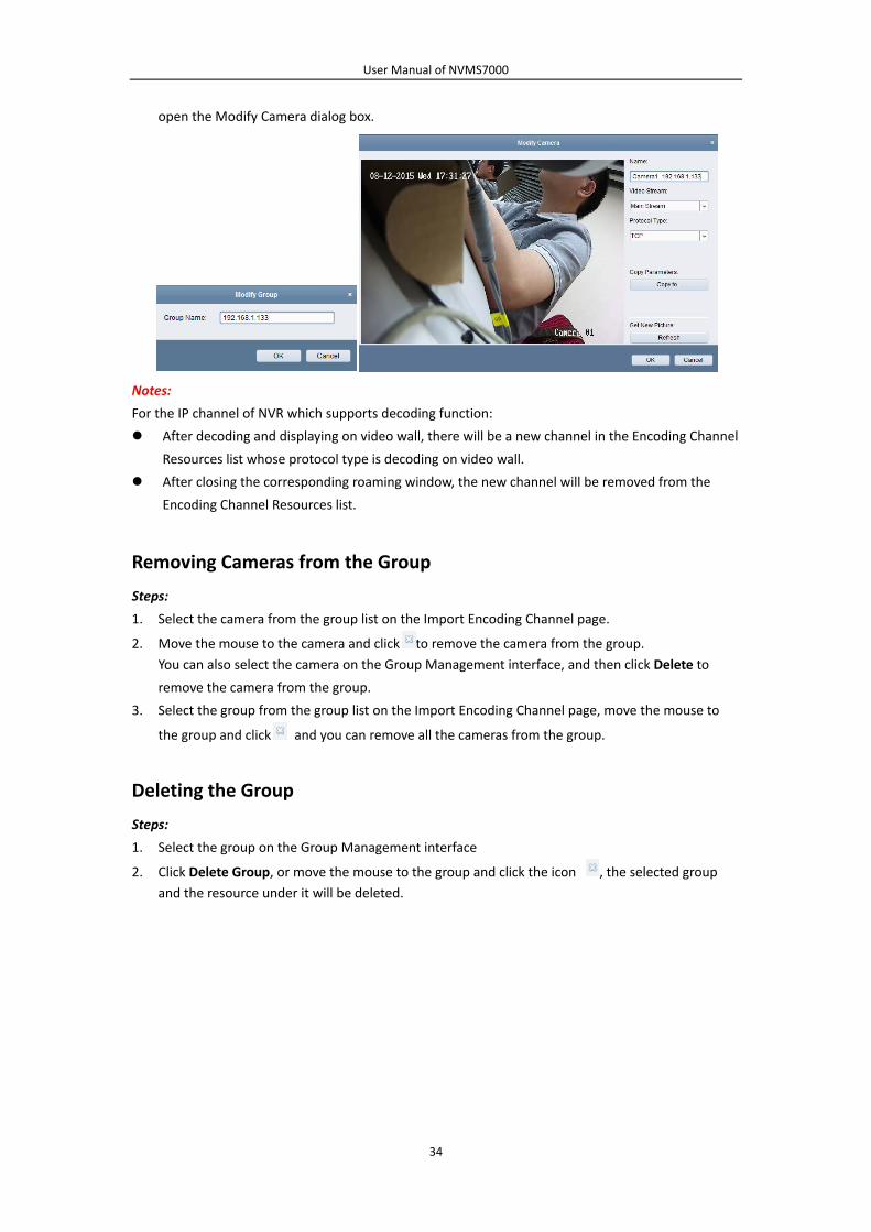
User Manual of NVMS7000
34
open the Modify Camera dialog box.
Notes:
For the IP channel of NVR which supports decoding function:
After decoding and displaying on video wall, there will be a new channel in the Encoding Channel
Resources list whose protocol type is decoding on video wall.
After closing the corresponding roaming window, the new channel will be removed from the
Encoding Channel Resources list.
Removing Cameras from the Group
Steps:
1. Select the camera from the group list on the Import Encoding Channel page.
2. Move the mouse to the camera and click to remove the camera from the group.
You can also select the camera on the Group Management interface, and then click Delete to
remove the camera from the group.
3. Select the group from the group list on the Import Encoding Channel page, move the mouse to
the group and click and you can remove all the cameras from the group.
Deleting the Group
Steps:
1. Select the group on the Group Management interface
2. Click Delete Group, or move the mouse to the group and click the icon , the selected group
and the resource under it will be deleted.

User Manual of NVMS7000
35
Chapter 4 Live View
Purpose:
For the surveillance task, you can view the live video of the added network cameras, video encoders
and video intercom device on the Main View page. And some basic operations are supported,
including picture capturing, manual recording, PTZ control, etc.
Before you start:
A camera group is required to be defined for live view.
You can set the rotate type if necessary in the Group Management. For details, refer to Modifying the
Group/Camera of Chapter 3.2Group Management.
Click the icon on the control panel,
or click View‐>Main View to open the Main View page.
Main View Page
1 View List
2 Camera List
3 PTZ Control Panel
4 Display Window of Live View
5 Live View Toolbar
Camera Status:
The camera is online and works properly.
The camera is in live view.
The camera is in recording status.
The camera is offline.
Notes:

User Manual of NVMS7000
36
If event (e.g., motion detection) is detected for the camera, the camera icon will display as
and the group icon will show as .
If the camera is offline, the client can still get the live video via the stream media server if the
stream media server is configured. The camera icon will display as .For configuring the stream
media server of the camera, refer to Chapter 10 Forwarding Video Stream through Stream Media
Server.
Live View Toolbar:
On the Main View page, the following toolbar buttons are available:
Save View Save the new settings for the current view.
Save View as Save the current view as another new view.
Stop Live View Stop the live view of all cameras.
Mute/Audio On Turn off/on the audio in live view
Resume/Pause
Auto‐switch Click to resume/pause the auto‐switch in live view.
Show/Hide the Menu Show/Hide the configuration menu of auto‐switch. Click again
to hide.
Previous Go for live view of the previous page.
Next Go for live view of the next page.
Window Division Set the window division.
Full Screen
Display the live view in full‐screen mode.
Press Esc, or you can move the mouse to the top of the screen
and click Quit Full Screen button to exit.
You can click Lock button to lock the screen, and you can click
Unlock and input the client admin password to unlock it.
For full screen auto‐switch, you can click Previous or Next
button to view the previous or next camera.
Right‐click on the display window in live view to open the Live View Management Menu:

User Manual of NVMS7000
37
The following buttons are available on the right‐click Live View Management Menu:
Stop Live View Stop the live view in the display window.
Capture Capture the picture in the live view process.
Other Capture Modes
Print Captured Picture: Capture a picture and print it.
Send Email: Capture the current picture and then send an
Email notification to one or more receivers. The captured
picture can be attached.
Custom Capture: Capture the current picture. You can edit its
name and then save it.
Start/Stop Recording Start/Stop the manual recording. The video file is stored in the
PC.
Open PTZ Control Enable PTZ control function on the display window. Click again
to disable the function.
Open Digital Zoom Enable the digital zoom function. Click again to disable the
function.
Switch to Instant Playback Switch to instant playback mode.
Fire Source Information
For thermal camera, click to display the fire source region,
display the maximum temperature information, locate the
maximum temperature region, or display the fire source
target.
Start/Stop Two‐way Audio Click to start/stop the two‐way audio with the device in live
view.
Start/Stop IP Two‐way
Audio
Click to start/stop the two‐way audio with the camera in live
view. This button is only available for the camera that supports
the IP two‐way audio function.
Enable/Disable Audio Click to enable/disable the audio in live view.
Camera Status
Display the status of the camera in live view, including the
recording status, signal status, connection number, etc.

User Manual of NVMS7000
38
Remote Configuration
Open the remote configuration page of the camera in live
view.
Synchronization Sync the camera in live view with the PC running the client
software.
Show/Hide Temperature
Information
For thermal camera, click to show or hide the temperature on
the live view image.
Fisheye Expansion
Enter the fisheye expansion mode. Only available when the
device is fisheye camera. For details, please refer to
Chapter4.7Live View in Fisheye Mode.
Start/Stop Master‐slave
Linkage
Click to start/stop locating or tracking the target according to
your demand. Only available when the device is fisheye
camera or box/bullet camera.
Unlock
Click to remote unlock the door if the device is door station,
outer door station or door station (V series).
Full Screen Display the live view in full screen mode. Click the icon again
to exit.
4.1 Starting and Stopping the Live View
Starting Live View for One Camera
Steps:
1. Open the Main View page.
2. Optionally, click the icon in live view toolbar to select the window division mode for live
view.
3. Click‐and‐drag the camera to the display window,
or double‐click the camera name after selecting the display window to start the live view.
Note: You can click‐and‐drag the video of the camera in live view to another display window if
needed.
Starting Live View for Camera Group
Steps:
1. Open the Main View page.
2. Click‐and‐drag the group to the display window,
or double‐click the group name to start the live view.
Note: The display window number is self‐adaptive to the camera number of the group.
Starting Live View in Default View Mode
Purpose:
The video of the added cameras can be displayed in different view modes. 4 frequently‐used default
view modes are selectable: 1‐Screen, 4‐Screen, 9‐Screen and 16‐Screen.
Steps:
1. Open the Main View page.

User Manual of NVMS7000
39
2. In the View panel, click the icon to expand the default view list.
3. Click to select the default view mode and the video of the added cameras will be displayed in a
sequence in the selected view.
Note: Click , and you can save the default view as a custom view.
Move the mouse to the view and the following icons are available:
Start Instant Playback Start the instant playback of the view.
Start Auto‐switch Start switching automatically of the view. For details,
please refer to Chapter 4.2Auto‐switch in Live View.
Starting Live View in Custom View Mode
Purpose:
The view mode can also be customized for the video live view.
Steps:
1. Open the Main View page.
2. In the View panel, click the icon to expand the custom view list. If there is custom view
available, you can click to start live view of the custom view.
3. Click to create a new view.
4. Input the view name and click Add. The new view is of 4‐Screen mode by default.
5. Optionally, click the icon in live view tool bar and select the screen layout mode for the new
view.
6. Click‐and‐drag the camera/group to the display window,
or double‐click the camera/group name in custom view mode to start the live view.
7. Click the icon to save the new view. You can also click to save the view as another
custom view.
Move the mouse to the custom view and the following icons are available:
Edit View Name Edit the name of the custom view.
Delete View Delete the custom view.
Start Instant Playback Start the instant playback of the view.

User Manual of NVMS7000
40
Stopping the Live View
Steps:
1. Select the display window.
2. Click the icon that appears in the upper‐right corner when the mouse pointer is over the
display window,
or click Stop Live View on the right‐click menu to stop the live view of the display window.
You can also click the button in live view toolbar to stop all the live view.
4.2 Auto‐switch in Live View
Camera Auto‐switch
Purpose:
The video stream of the cameras from the same group will switch automatically in a selected display
window in camera auto‐switch.
Steps:
1. Open the Main View page.
2. Select a display window for camera auto‐switch.
3. Click the icon in the toolbar and select or customize the switching interval.
4. Select a group and click the icon on the group node.
5. You can click the icon / to pause/resume the camera auto‐switch.
6. You can click or to view the live video of previous or next camera.
Single View Auto‐switch
Purpose:
The video of all the cameras on the camera list will switch automatically in a selected default view in
single view auto‐switch.
Steps:
1. Open the Main View page.
2. Click the icon in the toolbar and select or customize the switching interval.
3. Select a default view and click the icon on the selected view node.
4. You can click the icon / to pause/resume the single view auto‐switch.

User Manual of NVMS7000
41
5. You can click or to view the live video of previous or next camera.
Multi‐view Auto‐switch
Purpose:
The custom views will switch automatically in multi‐view auto‐switch. The custom views need to be
added before proceeding.
Steps:
1. Open the Main View page.
2. Click the icon in the toolbar and select the switching interval.
3. Click the icon on the custom view node.
4. You can click the icon / to pause/resume the multi‐view auto‐switch.
5. You can click or to view the live video of previous or next camera.
4.3 PTZ Control in Live View
The software provides PTZ control for cameras with pan/tilt/zoom functionality. You can set the preset,
patrol and pattern for the cameras on the PTZ Control panel. And you can also open window PTZ
control for the operations of PTZ cameras.
Click the icon to expand the PTZ Control panel.
The following buttons are available on the PTZ Control panel:
Zoom
Focus
Iris
3D Positioning
Auxiliary Focus
Lens Initialization
Light
Wiper
Manual Tracking
Menu
One‐touch Patrol
One‐touch Park

User Manual of NVMS7000
42
Notes:
For the analog speed dome, you can click to display its local menu. For detailed operation of
the menu, please refer to the User Manual of the speed dome.
For the speed dome with auto‐tracking function, you can enable the auto‐tracking (via right‐click
menu) for it and then click to manually track the target by clicking on the video.
For the one‐touch patrol function, you can click and the speed dome will start patrol from
the predefined preset No.1 to preset No.32 in order after a period of inactivity (park time). For
setting the park time, please refer to the User Manual of the speed dome.
For the speed dome with one‐touch park function, you can enable the one‐touch park by clicking
and the speed dome will save the current view to the preset No.32. The device starts to park
at preset No. 32 automatically after a period of inactivity (park time).For setting the parking time,
please refer to the User Manual of the speed dome.
Configuring the Preset
A preset is a predefined image position which contains information of pan, tilt, focus and other
parameters.
Perform the following steps to add a preset:
1. Click the Preset button to enter the PTZ preset configuration panel.
2. Click the direction buttons and other buttons on the PTZ control panel to steer the camera to the
desired view.
3. Select a PTZ preset number from the preset list and click .
4. Input the name of the preset in the pop‐up dialog box.
5. Click OK to save the settings.
To call a configured preset, double‐click the preset, or select the preset and click the icon .
You also perform the following steps to call the preset.
Steps:
1. Click to select a live view window.
2. For preset 1 to 9, click the corresponding number key (e.g., 4) to call the preset.
For other presets, click “[”, number keys (e.g., 124), and “]” to call the preset.
To modify a configured preset, select the preset from the list and click the icon .
To delete a configured preset, select the preset from the list and click the icon .

User Manual of NVMS7000
43
Configuring the Pattern
A pattern is a memorized, repeating series of pan, tilt, zoom, and preset functions.
Perform the following steps to add a pattern:
1. Click the Pattern button to enter the PTZ pattern configuration panel.
2. Click to start recording of this pattern path.
3. Use the direction buttons to control the PTZ movement.
4. Click to stop and save the pattern recording.
5. Click the icon to call the pattern. To stop calling the pattern, click .
6. (Optional) You can click to delete the selected pattern.
Click to delete all the patterns.
Configuring the Patrol
A patrol is a scanning track specified by a group of user‐defined presets, with the scanning speed
between two presets and the dwell time at the preset separately programmable.
Before you start:
Two or more presets for one PTZ camera need to be added.
Perform the following steps to add and call a patrol:
1. Click the Patrol button to enter the PTZ patrol configuration panel.
2. Select a track number from the drop‐down list.
3. Click to add a preset, and set the dwell time and patrol speed for the preset.
4. Repeat the above operation to add other presets to the patrol.
5. Optionally, you can click or to edit or delete a preset in the patrol path.
6. Click the icon to call the patrol. To stop calling the patrol, click .
Note: The preset dwell time can be set to 1 to 30 sec, and the patrol speed can be set to level 1 to 40.

User Manual of NVMS7000
44
4.4 Manual Recording and Capture
Toolbar in Each Live View Display Window:
In each live view display window, the following toolbar buttons are available:
Capture Capture the picture in the live view process. The capture picture
is stored in the PC.
Start/Stop Recording Start/Stop manual recording. The video file is stored in the PC.
Switch to Instant
Playback Switch to the instant playback mode.
Note: You can customize the icons and the icons’ order as desired in System Configuration. For details,
refer to Chapter 17.2.5Toolbar Settings.
Manual Recording in Live View
Purpose:
Manual Recording function allows you to record the live video on the Main View page manually and
the video files are stored in the local PC.
Steps:
1. Move the mouse pointer to the display window in live view to show the toolbar.
2. Click in the toolbar of the display window or on the right‐click Live View Management Menu
to start the manual recording. The icon turns to .
3. Click the icon to stop the manual recording.
A prompt box with the saving path of the video files you just recorded will pop up if all the
operations succeed.
Notes:
During the manual recording, an indicator appears in the upper‐right corner of the display
window.
The saving path of video files can be set on the System Configuration interface. For details, refer
toChapter17.2.4File Saving Path Settings.
For Guarding Vision device, the manual recording is not supported during live view.

User Manual of NVMS7000
45
Viewing Local Video Files
Steps:
1. Click File‐>Open Video File to open the Video Files page.
2. Select the camera to be searched from the Camera Group list.
3. Click the icon to specify the start time and end time for the search.
4. Click Search. The video files recorded between the start time and end time will be displayed.
Select the video file, and click Delete. You can delete the video file.
Select the video file, and click Send Email. You can send an Email notification with the selected
video file attached.
Select the video file, and click Save as. You can save a new copy of the video file.
Note: To send an Email notification, the Email settings need to be configured before proceeding. For
details, refer toChapter17.2.8Email Settings.
Double‐click the video file and the video file can be played back locally.
The following buttons are available on the local playback page:
CIF/4CIF Display the video in cif/4cif resolution.
Full Screen Display the local playback page in full screen mode.

User Manual of NVMS7000
46
Close Close the local playback page of the video files.
Pause/Play Pause / Start the playback of the video files.
Stop Stop the playback of the video files.
Speed Set the playback speed.
Single Frame Play back the video files frame by frame.
Digital Zoom Enable the digital zoom function. Click again to disable.
Enable/Disable Audio Click to enable/disable the audio in the local playback.
Capture Capture the picture in the playback process.
Capturing Picture in Live View
Steps:
1. Move the mouse pointer to the display window in live view to show the toolbar.
2. Click the icon in the toolbar of the display window or on the right‐click Live View
Management Menu.
A small window of the captured picture will be displayed to notify whether the capturing
operation is done or not.
Note: The saving path of the captured pictures can be set on the System Configuration interface. For
details, refer toChapter17.2.4File Saving Path Settings.
Viewing Captured Pictures
The pictures captured in live view are stored in the PC running the software. You can view the
captured pictures if needed.
Steps:
1. Click File‐>Open Image File to open the Captured Images page.
2. Select the camera to be searched from the Camera Group list.
3. Click the icon to specify the start time and end time for the search.
4. Click Search. The pictures captured between the start time and end time will be displayed.
5. Double‐click the captured picture to enlarge it for a better view.
Select the captured picture, and click Print. You can print the selected picture.
Select the captured picture, and click Delete. You can delete the selected picture.
Select the captured picture, and click Send Email. You can send an Email notification with the
selected picture attached.
Select the captured picture, and click Save as. You can save a new copy of the selected picture.

User Manual of NVMS7000
47
4.5 Instant Playback
Purpose:
The video files can be played back instantly on the Main View page. Instant playback shows a piece of
the video which was remarkable, or which was unclear on the first sight. Thus, you can get an
immediate review if needed.
Before you start:
The video files need to be recorded on the storage devices, such as the SD/SDHC cards and HDDs on
the DVRs, NVRs, Network Cameras, etc., or on the storage servers.
Steps:
1. Start the live view and move the mouse to the display window to show the toolbar. You can also
move the mouse to default view or custom view and click to enable the instant playback of
the selected view.
2. Click the icon in the toolbar and a list of time periods pops up.
30s, 1 min, 3 min, 5 min, 8 min, and 10 min are selectable.
3. Select a time period to start the instant playback.
Example: If the current time of the live view is 09:30:00, and you select 3 min, then the instant
playback will start from 09:27:00.
4. Click the icon again to stop the instant playback and go back for the live view.
Note: During the instant playback, an indicator appears in the upper‐right corner of the display
window.

User Manual of NVMS7000
48
On the instant playback page, the following toolbar buttons are available:
Reverse Playback Play back the video file reversely.
Pause/Start Playback Pause/Start the playback of the video files.
Stop Playback Stop the playback of all cameras.
Slow Forward/Fast Forward Decrease / Increase the play speed of the playback.
Single Frame (Reverse) Play back the video files frame by frame (reversely).
Right‐click on the display window to open the Instant Playback Management Menu:
The following buttons are available on the right‐click Instant Playback Management Menu:
Reverse Playback Play back the video file reversely.
Pause/Play Pause/ Start the instant playback in the display window.
Stop Stop the instant playback and return to the live view mode.
Fast
Forward/Slow
Forward
Increase/Decrease the play speed of the instant playback.
Single Frame
(Reverse) Play back the video file frame by frame (reversely).

User Manual of NVMS7000
49
Open Digital
Zoom
Enable the digital zoom function. Click again to disable the
function.
Capture Capture the picture in the instant playback process.
Print Captured
Picture Capture the current picture and then print the picture.
Send Email Capture the current picture and then send an Email notification to
one or more receivers. The captured picture can be attached.
Start/Stop
Recording Start/Stop clipping the video files.
Enable/Disable
Audio Click to turn on/off the audio in instant playback.
Switch to Live
View Switch to live view mode.
Full Screen Display the instant playback in full screen mode. Click again to exit.
4.6 Custom Window Division
Purpose:
The client software provides multiple kinds of pre‐defined window division. You can also set custom
window division as desired.
Steps:
1. Click on the live view toolbar and select to pop up the custom window division dialog
box.
2. Click Add to open the custom window division adding dialog box.
Note: Up to 5 custom window divisions can be added.
3. Set a name for the new window division as desired and click OK to save the settings.

User Manual of NVMS7000
50
4. You can edit the name, window division (3x3, 4x4, 5x5) for it.
5. Click‐and‐drag you mouse to select the adjacent windows, and click Joint to joint them as a
whole window. You can also click Cancel to cancel the jointing.
6. Click Save to confirm the settings. Click to back to the Main View page. Then you can click
and select the custom window division for playing live video.
Notes:
You can also enter the Remote Playback page and perform the steps above to configure the
custom window division.
For remote playback, up to 16 windows can be played back at the same time. The custom
window division with more than 16 windows is invalid for playback.
4.7 Live View in Fisheye Mode
Purpose:
The live video of the camera can be played in fisheye expansion mode.
Steps:
1. Start the live view (refer to Chapter4.1Starting and Stopping the Live View).
2. Right‐click on the video and select Fisheye Expansion to enter the Fisheye Expansion window.
3. Select the mounting type of the fisheye camera according to the actual mounting position.
4. You can select the expanding mode for live view as desired.
Note: For some devices, you can select the mounting type of the device and the related
expanding mode will be listed.

User Manual of NVMS7000
51
Fisheye: In the Fisheye view mode, the whole wide‐angle view of the camera is displayed.
This view mode is called Fisheye because it approximates the vision of a fish’s convex eye.
The lens produces curvilinear images of a large area, while distorting the perspective and
angles of objects in the image.
Panorama/Dual‐180oPanorama/360oPanorama: In the Panorama view mode, the distorted
fisheye image is trans formed to normal perspective image by some calibration methods.
PTZ: The PTZ view is the close‐up view of some defined area in the Fisheye view or
Panorama view, and it supports the electronic PTZ function, which is also called e‐PTZ.
Note: Each PTZ view is marked on the Fisheye view and Panorama view with a specific
navigation box. You can drag the navigation box on the Fisheye view or Panorama view to
adjust the PTZ view, or drag the PTZ view to adjust the view to the desired angle.
5. You can right click on the window and select Capture to capture the picture in the live view
process. The capture picture is stored in the PC.
6. Right‐click on a playing window and you can switch the selected window to full‐screen mode
Press ESC key on the keyboard or right‐click on the window and select Quit Full Screen to exit the
full‐screen mode.
PTZ Control In PTZ mode, you can use the PTZ control to adjust the PTZ window.
Note: The PTZ panel varies according to different devices.
Select a PTZ window, and click one of the direction buttons to adjust the view angle.
Note: Click‐and‐drag the No. label in the fisheye or panorama window will change the view angle
of the PTZ window as well.
Select a PTZ window, and click to start auto‐scan, and click it again to stop auto‐scan.
: Drag the slider to adjust the speed for PTZ movement.
: Zoom in or zoom out the selected PTZ window by clicking or . Or you can
scroll the mouse wheel to zoom in or zoom out.
Preset Note: The preset is only supported by specific fisheye camera.
A preset is a user‐defined monitor position/point. You can simply call the preset No. to change the

User Manual of NVMS7000
52
monitor scene to the defined position. Please follow the steps below to configure the preset.
Steps:
1. Click Preset tab to enter the preset configuration interface.
2. Select a PTZ window, and adjust the scene to the place you want to mark as a preset.
3. Click , input the preset name, and click OK to save a preset.
4. (Optional) Click to call the configured preset.
5. (Optional) Click to delete the configured preset.
Patrol Note: The preset is only supported by specific fisheye camera.
A patrol is a scanning track specified by a group of user‐defined presets, with the scanning speed
between two presets and the dwell time at the preset separately programmable. Please follow the
steps below to configure the patrol.
Note:
At least 2 presets have to be configured before you configure the patrol.
Steps:
1. Click patrol tab to enter the patrol configuration interface.
2. Select a path No. from the drop‐down list.
3. Click to add the configured presets, and set the dwell time and patrol speed for the preset.
4. Repeat the above operation to add other presets to the patrol.
5. Click to start the patrol, and click to stop patrol.
6. Optionally, you can click or to edit or delete a preset in the patrol path.
Notes:
Up to 256 presets can be configured.
Up to 32 patrols can be set.
The dwell time ranges from 1 to 120s.
The patrol speed ranges from 1 to 40.

User Manual of NVMS7000
53
4.8 Other Functions in Live View
There are some other functions supported in the live view, including digital zoom, two‐way audio,
camera status and synchronization.
Auxiliary Screen Preview
The live video can be displayed on different auxiliary screens for the convenient preview of multiple
monitoring scenes. Up to 3 auxiliary screens are supported.
Digital Zoom
Use the left key of mouse to drag a rectangle area in the lower‐right/upper‐left direction, and then the
rectangle area will zoom in/out. You can also use the mouse wheel for zooming in or restoring of the
video in digital zoom mode.
Channel‐zero
For the channel‐zero of the device, you can hold the Ctrl key and double‐click to display the specific
channel. Hold the Ctrl key and double‐click again to restore.
Two‐way Audio
Two‐way audio function enables the voice talk of the camera. You can get not only the live video but
also the real‐time audio from the camera. If the device has multiple two‐way audio channels, you can
select the channel to start two‐way audio.
The two‐way audio can be used for only one camera at one time.
Camera Status
The camera status, such as recording status, signal status, connection number, etc., can be detected
and displayed for check. The status information refreshes every 10 seconds.
Synchronization
The synchronization function provides a way to synchronize the device clock with the PC which runs
the client software.

User Manual of NVMS7000
54
Chapter 5 Remote Storage Schedule
Settings and Playback
When the video storage devices are the HDDs, Net HDDs, SD/SDHC cards on the local device, or the
remote storage server connected, you can set the recording schedule or capture schedule for the
cameras for the continuous, alarm triggered or command triggered recording or capture. And the
video files can be searched for the remote playback.
5.1 Remote Storage
Purpose:
The video files and captured pictures can be stored on the HDDs, Net HDDs, SD/SDHC cards on the
local device, or the storage server connected.
Click the icon on the control panel,
or click Tool‐>Storage Schedule to open the Storage Schedule page.
5.1.1 Storing on the DVR, NVR, or Network Camera
Purpose:
Some local devices, including the DVRs, NVRs, and Network Cameras, provide storage devices such as
the HDDs, Net HDDs and SD/SDHC cards for video files. You can set a recording schedule or capture
schedule for the channels of the local devices.
Note: The pictures captured through the capture schedule are stored on the local device and can be
searched on the remote configuration page of the device.
Before you start:

User Manual of NVMS7000
55
The newly installed storage devices need to be formatted. Go to the remote configuration page of the
device, click Storage‐>General, select the HDD or SD/SDHC card, and click Format to initialize the
selected storage device.
Steps:
1. Open the Recording Schedule page.
2. Select the camera in the Camera Group list.
3. Check the checkbox Recording Schedule/Capture Schedule under Storage of Encoding Server to
enable device local recording or capture.
4. Select the record or capture schedule template from the drop‐down list.
All‐day Template: for all‐day continuous recording.
Weekday Template: for working‐hours continuous recording from 8:00 AM to 8:00 PM.
Event Template: for the event triggered recording.
Template 01 to 08: fixed templates for specific schedules. You can edit the templates if needed.
Custom: can be customized as desired.
If you need to edit or customize the template, refer to Configuring Recording Schedule Template.
5. Click Advanced Settings to set the recording parameters. For details, refer to Table 5.1 Advanced
Recording Settings and Table5.2 Advanced Capture Settings.
Note: The displayed items vary with the devices.
6. Optionally, click Copy to… to copy the recording schedule settings to other channels.
7. Click Save to save the settings.
Table 5. 1 Advanced Recording Settings
Parameters Descriptions
Pre‐record Normally used for the event triggered record, when you want to record before
the event happens
Post‐record After the event finished, the video can also be recorded for a certain time.
Keep Record Files for The time for keeping the video files in the storage device, once exceeded, the

User Manual of NVMS7000
56
files will be deleted. The files will be saved permanently if the value is set as 0.
Redundant Record Save the video files not only in the R/W HDD but also in the redundant HDD.
Record Audio Record the video files with audio or not.
Video Stream
Select the stream type for the recording.
Note: For specific type of devices, you can select Dual‐Stream for recording
both main stream and sub‐stream of the camera. In this mode, you can switch
the stream type during remote playback. Refer to Chapter 5.2.1Normal
Playback for stream switch during playback.
Table 5. 2 Advanced Capture Settings
Parameters Descriptions
Resolution Select the resolution for the continuous or event captured pictures.
Picture Quality Set the quality for the continuous or event captured pictures.
Interval Select the interval which refers to the time period between two capturing
actions.
Captured Picture
Number Set the picture number for event capture.
Configuring Recording Schedule Template
Perform the following steps to configure the recording schedule template:
If Template 01 to 08 is selected from the drop‐down list, start from step 1;
If Custom is selected from the drop‐down list, start from step 2.
1. Click Edit to enter the Templates Management interface. Select the template to be set and you
can edit the template name.
2. Set the time schedule for the selected template.
refers to normal schedule record. The schedule time bar is marked with .
refers to the schedule record for the event. The schedule time bar is marked
with .
refers to the schedule record triggered by command. The schedule time bar is
marked with .
Note: Record triggered by command is only available for the ATM transactions when the ATM DVR
is added toNVMS7000.
When the cursor turns to , you can set the time period.
When the cursor turns to , you can move the selected time bar you just edited. You can also
edit the displayed time point to set the accurate time period.
When the cursor turns to , you can lengthen or shorten the selected time bar.
3. Optionally, you can select the schedule time bar,
and then click the icon to delete the selected time bar,
or click the icon to delete all the time bars,
or click the icon to copy the time bar settings to the other dates.
4. Click OK to save the settings.
You can click Save as Schedule Template on the Custom Schedule interface, and then the custom
template can be saved as template 01 to 08.
Note: Up to 8 time periods can be set for each day in the recording schedule.

User Manual of NVMS7000
57
5.1.2 Storing on Storage Device
Purpose:
You can add storage device to the client for storing the video files and pictures of the added encoding
devices and you can search the files for remote playback. The storage device can be storage server,
CVR (Center Video Recorder) or other NVR. Here we take the settings of storage server as an example.
Before you start:
The storage server application software needs to be installed and it is packed in the
NVMS7000software package. When installing the NVMS7000, check the checkbox Storage Server to
enable the installation of storage server.
Adding the Storage Server
Steps:
1. Click the shortcut icon on the desktop to run the storage server.
Notes:
You can also record the video files on the storage server installed on other PC.
If the storage server port (value: 8000) is occupied by other service, a dialog box will pop up.
You should change the port No. to other value to ensure the proper running of the storage
server.
2. Open the Device Management page and click the Device tab.

User Manual of NVMS7000
58
3. Click Device to display the Device list. For adding Storage Server, refer to Chapter 3.1Adding the
Device.
Formatting the HDDs
The HDDs of the storage server need to be formatted for the video file and picture storage.
Steps:
1. Select the added storage server from the list and click Remote Configuration.
2. Click Storage‐>General, to enter the HDD Formatting interface.
3. Select the HDD from the list and click Format. You can check the formatting process from the
process bar and the status of the formatted HDD changes from Unformatted to Normal Status.
Note: Formatting the HDDs is to pre‐allocate the disk space for storage and the original data of the
formatted HDDs will not be deleted.
SAN and CVR Configuration
Purpose:
Client provides SAN configuration and CVR configuration to conveniently set the logical volume and
CVR function for CVR device. For detailed introduction about SAN configuration and CVR configuration,

User Manual of NVMS7000
59
refer to the User Manual of the CVR.
Note: This function should be supported by the device.
Select the added CVR from the list and click CVR Configuration or SAN Configuration.
Configuring Storage Schedule
Before you start:
The storage server needs to be added to the client software and the HDDs need to be formatted for
the video file storage.
Steps:
1. Open the Storage Schedule page.
2. Select the camera from the Camera Group list.
3. Select the storage server from the Storage Server drop‐down list.
Note: You can click Storage Server Management to add, edit or delete the storage server.
4. Check the checkbox Recording Schedule to enable storing the video files.
You can also check the checkbox Picture Storage to store the alarm pictures of the camera when
event occurs.
For the network cameras with the function of heat map or people counting, the Additional
Information Storage checkbox is available. You can click VCA Config to set the VCA rule for the
camera, and check the Additional Information Storage checkbox and the heat map, people
counting data and road traffic data will be uploaded to the storage server. Please refer to Chapter
18.1Heat Map and Chapter 18.2People Counting Statistics for checking the data.
Note: For detailed configuration about setting the VCA rule, please refer to the User Manual of
the camera.
5. Select the schedule template for recording from the drop‐down list.
If you need to edit or customize the template, refer to Configuring Recording Schedule Template.
6. Click Advanced Settings to set the pre‐record time, post‐record time and other parameters for
recording.
7. Click Set Quota to enter the HDD management interface of the storage server. You can set the
corresponding quota ratio for record, picture and additional information.
Example: If you set the record quota as 60%, then the 60% of the storage space can be used for
storing the video files.
8. Click Save to save the settings.
Note: The storage server supports storage of line crossing detection alarm, intrusion detection alarm,
region entrance detection alarm, region exiting detection alarm, fast moving detection alarm, people
gathering detection alarm, loitering detection alarm, parking detection alarm, object removal

User Manual of NVMS7000
60
detection alarm, and unattended baggage detection alarm recording. For details, refer to Chapter 6
Event Management.
5.2 Remote Playback
Purpose:
The video files stored on the local device or the storage server can be searched by camera or
triggering event, and then can be played back remotely.
Before you start:
You can set to play back the video files stored in the local device, in the storage server, or both in the
storage server and local device. For details, refer to Chapter 17.2.2Live View and Playback Settings.
Optionally, you can set the cameras rotate direction for playback in Group Management. Refer to
Modifying the Group/Camera of Chapter 3.2Group Management.
Click the icon on the control panel,
or click View‐>Remote Playback to open the Remote Playback page.
Remote Playback Page
1 Camera List
2 Display Window of Playback
3 Playback Control Buttons
4 Timeline
5 Calendars
6 Search Condition
5.2.1 Normal Playback
Purpose:
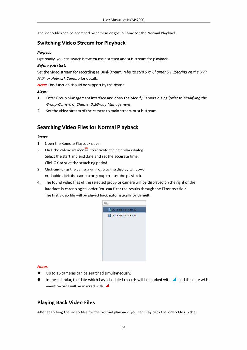
User Manual of NVMS7000
61
The video files can be searched by camera or group name for the Normal Playback.
Switching Video Stream for Playback
Purpose:
Optionally, you can switch between main stream and sub‐stream for playback.
Before you start:
Set the video stream for recording as Dual‐Stream, refer to step 5 of Chapter 5.1.1Storing on the DVR,
NVR, or Network Camera for details.
Note: This function should be support by the device.
Steps:
1. Enter Group Management interface and open the Modify Camera dialog (refer to Modifying the
Group/Camera of Chapter 3.2Group Management).
2. Set the video stream of the camera to main stream or sub‐stream.
Searching Video Files for Normal Playback
Steps:
1. Open the Remote Playback page.
2. Click the calendars icon to activate the calendars dialog.
Select the start and end date and set the accurate time.
Click OK to save the searching period.
3. Click‐and‐drag the camera or group to the display window,
or double‐click the camera or group to start the playback.
4. The found video files of the selected group or camera will be displayed on the right of the
interface in chronological order. You can filter the results through the Filter text field.
The first video file will be played back automatically by default.
Notes:
Up to 16 cameras can be searched simultaneously.
In the calendar, the date which has scheduled records will be marked with and the date with
event records will be marked with .
Playing Back Video Files
After searching the video files for the normal playback, you can play back the video files in the

User Manual of NVMS7000
62
following two ways:
Playback by File List
Select the video file from the search result list, and then click the icon on the video file,
or double‐click the video file to play the video on the display window of playback.
You can also select a display window and click the icon in the toolbar to play back the
corresponding video file.
Playback by Timeline
The timeline indicates the time duration for the video file, and the video files of different types
are color coded. Click on the timeline to play back the video of the specific time.
You can click or to scale up or scale down the timeline bar.
You can drag the timeline bar to go to the previous or the next time period.
You can use the mouse wheel to zoom in or zoom out on the timeline.
Normal Playback Toolbar:
On the Normal Playback page, the following toolbar buttons are available:
Reverse Playback Play back the video file reversely.
Pause/Start Playback Pause/Start the playback of the video files.
Stop Playback Stop the playback of all cameras.
Single Frame
(Reverse) Play back the video files frame by frame reversely.
Single Frame Play back the video files frame by frame.
Slow Forward/Fast
Forward Decrease/Increase the play speed of the playback.
Volume Click to turn on/off the audio and adjust the audio volume.

User Manual of NVMS7000
63
Event Playback Search the recordings triggered by event, such as motion
detection, video loss or video tampering.
ATM Playback Search the recordings of ATM devices.
VCA Playback Set the VCA rule to the searched video files that VCA event
occurs, including VCA Search, Intrusion and Line Crossing.
Window Division Set the window division.
Full Screen Display the video playback in full‐screen mode. Press ESC to exit.
Async/Sync Playback Click to play back the video files synchronously/asynchronously.
Download Download the video files of the camera and the video files are
stored in the PC. You can select to download by file or by date.
Tag
Add default tag for the video file to mark the important video
point. You can edit the tag or go to the tag position via the
right‐click menu.
Filter Display the record types as desired. E.g., you can select to
display only the event recording.
Date The day that has video files will be marked with .
Right‐click on the display window in playback to open the Playback Management Menu:
The following items are available on the right‐click Playback Management Menu:
Reverse Playback Play back the video file reversely.
Pause/Start Pause/Start the playback.
Stop Stop the playback.
Fast Forward Play back the video file at a faster speed.
Slow Forward Play back the video file at a slower speed.
Single Frame (Reverse) Play back the video file frame by frame (reversely).
Open Digital Zoom Enable the digital zoom function. Click again to disable the
function.
Tag Control Add default (default tag name TAG) or custom tag (customized
tag name) for the video file to mark the important video point.

User Manual of NVMS7000
64
You can also edit the tag or go to the tag position conveniently.
Accurate Positioning Set the accurate time point to play back the video file.
Capture Capture the picture in the playback process.
Print Captured Picture Capture a picture and print it.
Send Email Capture the current picture and then send an Email notification
to one or more receivers. The captured picture can be attached.
Start/Stop Recording Start/Stop the manual recording. The video file is stored in the
PC.
Download Download the video files of the camera and the video files are
stored in the PC. You can select to download by file or by date.
Enable/Disable Audio Click to enable/disable the audio in playback.
Fisheye Expansion Enter the fisheye playback mode.
Full Screen Display the playback in full‐screen mode. Click the icon again to
exit.
Downloading Video Files
During playback, you can click on the toolbar to download the video files of the camera to the
local PC. You can select to download by file, by date, or by tag.
Download by Files
Steps:
1. Click Download by Files tab in the File Download interface. You can view the video files
information of selected camera.
2. Check the checkbox of the video file and the total size of the selected files will be shown below.
3. Click Download to start downloading the file to the local PC.
You can input the flow (0 to 32768kbps) and click Set to control the downloading speed.
4. Optionally, you can click Stop to stop downloading manually.

User Manual of NVMS7000
65
Download by Date
Steps:
1. Click Download by Date tab in the File Download interface.
2. Check the checkbox of the time duration to enable it, and click to set the start and end time.
3. Click Download to start downloading the file to the local PC. The progress bar shows the
downloading process.
You can input the flow (0 to 32768kbps) and click Set to control the downloading speed.
4. Optionally, you can click Stop to stop downloading manually.

User Manual of NVMS7000
66
Note: When downloading video file of one time duration, you can set to merge the video files. The
video files in the set time duration can be merged for downloading. For configuring merging
downloaded video files, refer to Chapter 17.2.2Live View and Playback Settings.
5.2.2 Alarm Input Playback
Purpose:
When the alarm input is triggered and the linked video can be searched for Alarm Input Playback and
this function requires the support of the connected device.
Searching Video Files for Alarm Input Playback
Steps:
1. Open the Remote Playback page.
2. Click to show the Alarm Input panel on the left.
3. (Optional) Click the calendars icon to activate the calendars dialog.
Select the start and end date and set the accurate time, and click OK.
4. Click‐and‐drag the alarm input to the display window,
or double‐click the alarm input to start the playback.
5. The found video files of the selected alarm input will be displayed on the right of the interface.
You can filter the results through the Filter text field.
Playing Back Video Files
After searching the video files triggered by alarm input, you can play back the video files in the
following two ways:
Playback by File List
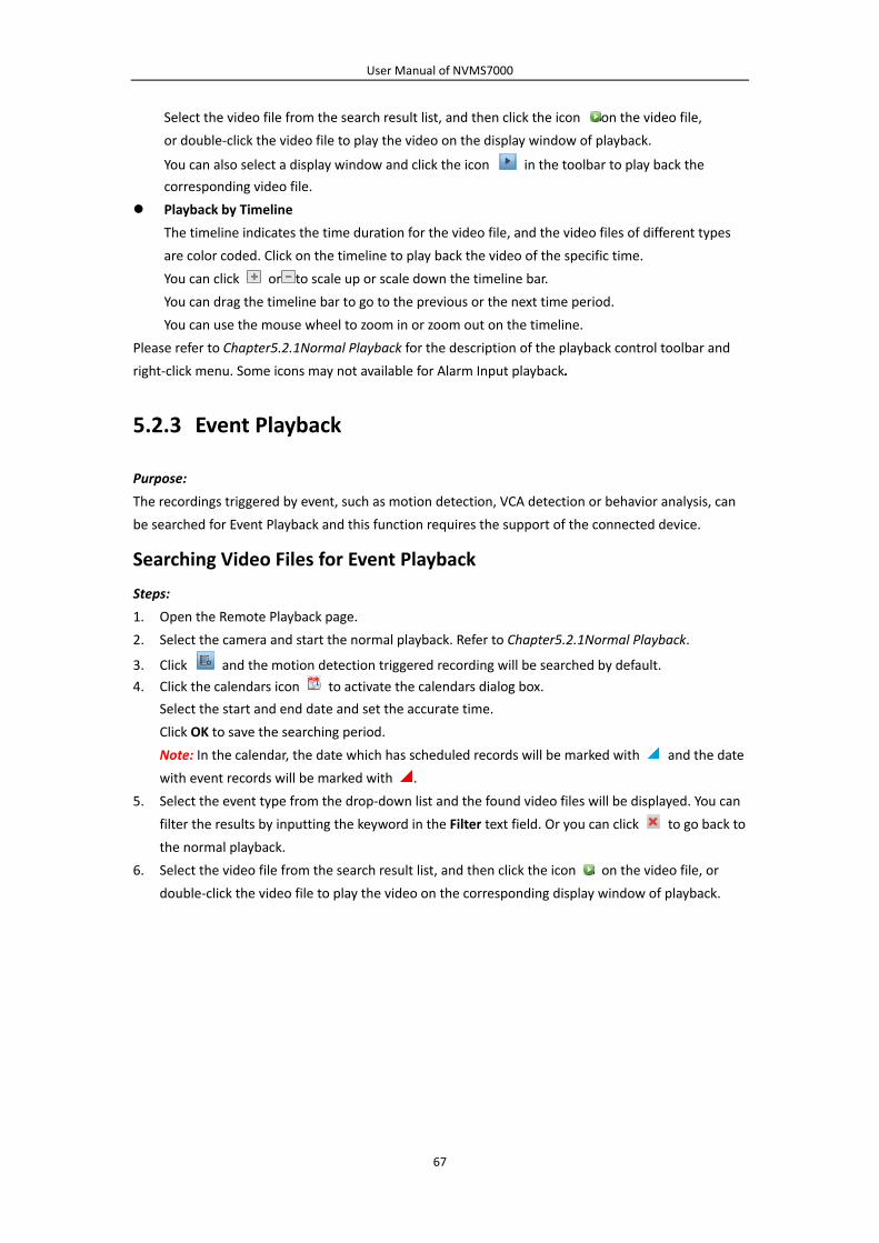
User Manual of NVMS7000
67
Select the video file from the search result list, and then click the icon on the video file,
or double‐click the video file to play the video on the display window of playback.
You can also select a display window and click the icon in the toolbar to play back the
corresponding video file.
Playback by Timeline
The timeline indicates the time duration for the video file, and the video files of different types
are color coded. Click on the timeline to play back the video of the specific time.
You can click or to scale up or scale down the timeline bar.
You can drag the timeline bar to go to the previous or the next time period.
You can use the mouse wheel to zoom in or zoom out on the timeline.
Please refer to Chapter5.2.1Normal Playback for the description of the playback control toolbar and
right‐click menu. Some icons may not available for Alarm Input playback.
5.2.3 Event Playback
Purpose:
The recordings triggered by event, such as motion detection, VCA detection or behavior analysis, can
be searched for Event Playback and this function requires the support of the connected device.
Searching Video Files for Event Playback
Steps:
1. Open the Remote Playback page.
2. Select the camera and start the normal playback. Refer to Chapter5.2.1Normal Playback.
3. Click and the motion detection triggered recording will be searched by default.
4. Click the calendars icon to activate the calendars dialog box.
Select the start and end date and set the accurate time.
Click OK to save the searching period.
Note: In the calendar, the date which has scheduled records will be marked with and the date
with event records will be marked with .
5. Select the event type from the drop‐down list and the found video files will be displayed. You can
filter the results by inputting the keyword in the Filter text field. Or you can click to go back to
the normal playback.
6. Select the video file from the search result list, and then click the icon on the video file, or
double‐click the video file to play the video on the corresponding display window of playback.

User Manual of NVMS7000
68
Playing Back Video Files
After searching the recordings triggered by the event, you can play back the video files in the following
two ways:
Playback by File List
Select the video file from the search result list, and then click the icon in the toolbar, or click
the icon on the video file,or double‐click the video file to play the video on the corresponding
display window of playback.
Playback by Timeline
The timeline indicates the time duration for the video file. Click on the timeline to play back the
video of the specific time.
You can click or to scale up or scale down the timeline bar.
You can drag the timeline bar to go to the previous or the next time period.
You can use the mouse wheel to zoom in or zoom out on the timeline.
Event Playback Toolbar:
On the Remote Playback page, the following toolbar buttons are available:
Reverse Playback Play back the video file reversely.
Pause/Start Playback Pause/Start the playback of the video files.
Stop Playback Stop the playback of all cameras.
Single Frame (Reverse) Play back the video files frame by frame reversely.
Single Frame Play back the video files frame by frame.
Previous Event Go to the playback of the previous event.
Next Event Go to the playback of the next event.
Slow Forward/Fast Forward Decrease / Increase the play speed of the playback.

User Manual of NVMS7000
69
Volume
Click to turn on/off the audio and adjust the audio
volume.
Full Screen Display the video playback in full screen mode. Press
ESC to exit.
Download Download the video files of the camera and the video
files are stored in the PC.
Date The day that has video files will be marked with .
Please refer to Chapter 5.2.1Normal Playback for the description of the right‐click menu. Some icons
may not available for event playback.
Note: You can set the pre‐play time for event playback in System Configuration. By default, it is 30s.
For configuring the pre‐play time, refer to Chapter 17.2.2Live View and Playback Settings.
5.2.4 ATM Playback
Purpose:
Search the video files for ATM DVR.
Note: This function should be supported by the device and the device should be configured with
transaction rules. For details, please refer to the User Manual of the device.
Searching Video Files for ATM Playback
Steps:
1. Open the Remote Playback page.
2. Select the camera of the ATM DVR and start the normal playback. Refer to Chapter 5.2.1Normal
Playback.
3. Click to enter the ATM playback interface.
4. Enter the search conditions.
: Input the card number that is contained in the ATM information.
: Check the checkbox and select the transaction type for query, and input the related
transaction amount.
File Type: Select the type of the video file to be searched.
5. Click the calendars icon to activate the calendars dialog.
Select the start and end date and set the accurate time.
Click OK to save the searching period.
6. Click Search and the matched files will be displayed. You can filter the results through the Filter
text field.
7. Double‐click a file for playback. Or you can click to go back to the normal playback.
Playing Back Video Files
After searching the recordings, you can play back the video files in the following two ways:
Playback by File List
Select the video file from the search result list, and then click the icon in the toolbar, or click
the icon on the video file,or double‐click the video file to play the video on the corresponding
display window of playback.

User Manual of NVMS7000
70
Playback by Timeline
The timeline indicates the time duration for the video file. Click on the timeline to play back the
video of the specific time.
You can click or to zoom in or zoom out the timeline bar.
You can drag the timeline bar to go to the previous or the next time period.
You can use the mouse wheel to zoom in or zoom out on the timeline.
Please refer to Chapter5.2.1Normal Playback for the description of the playback control toolbar and
right‐click menu. Some icons may not available for ATM playback.
5.2.5 POS Playback
Purpose:
Search the video files which contain POS information.
Note: This function should be supported by the device and the device should be configured with POS
text overlay. For details, please refer to the User Manual of the device.
Searching Video Files for POS Playback
Steps:
1. Open the Remote Playback page.
2. Select the camera and start the normal playback. Refer to Chapter 5.2.1Normal Playback.
3. Click to enter the POS playback interface.
4. Enter the search conditions.
Keywords: Input the keywords that are contained in the POS information. You can input up to 3
keywords by separating each one with a comma.
Filter: If you input more than one keyword for query, you can select “or(|)” to search the POS
information containing any of the keywords, or select “and(&)” to search the POS information
containing all of the keywords.
Case Sensitive: Check the checkbox to search the POS information with case‐sensitivity.
7. Click the calendars icon to activate the calendars dialog box.
Select the start and end date and set the accurate time.
Click OK to save the searching period.
5. Click Search and the matched files will be displayed. You can filter the results through the Filter
text field.
6. Double‐click a file for playback. Or you can click to go back to the normal playback.
Playing Back Video Files
After searching the recordings, you can play back the video files in the following two ways:
Playback by File List
Select the video file from the search result list, and then click the icon in the toolbar, or click
the icon on the video file, or double‐click the video file to play the video on the
corresponding display window of playback.
Playback by Timeline
The timeline indicates the time duration for the video file. Click on the timeline to play back the

User Manual of NVMS7000
71
video of the specific time.
You can click or to zoom in or zoom out the timeline bar. You can also use the mouse wheel
to zoom in or zoom out on the timeline.
You can drag the timeline bar to go to the previous or the next time period.
Please refer to Chapter5.2.1Normal Playback for the description of the playback control toolbar,
right‐click menu and downloading record files. Some icons may not be available for POS playback.
5.2.6 Synchronous Playback
Purpose:
In synchronous playback, the video files can be played back in synchronization.
Note: Video files from up to 16 cameras can be played back simultaneously.
Steps:
1. Search the video files for the normal playback (Chapter5.2.1Normal Playback). At least two
cameras are during playback.
2. Click in the toolbar to enable the synchronous playback. The camera under playback will
start synchronous playback.
3. To disable the synchronous playback, click the icon .
5.2.7 VCA Playback
Purpose:
You can set VCA rule to the searched video files and find the video that VCA event occurs, including
VCA Search, Intrusion and Line Crossing. This function helps to search out the video that you may be
more concerned and mark it with red color.
VCA Search: Get all the related motion detection events that occurred in the pre‐defined region.
Intrusion Detection: Detect whether there are people, vehicles and other moving objects
intruding into the pre‐defined region.
Line Crossing Detection: Bi‐directionally detect people, vehicles and other moving objects that
cross a virtual line.

User Manual of NVMS7000
72
Note: For some devices, you can filter the searched video files by setting the advanced attributes,
such as the gender and age of the human and whether he/she wears glasses.
Steps:
1. Open the Remote Playback page.
2. Select the camera and start the normal playback. Refer toChapter5.2.1Normal Playback.
3. Click to enter the VCA playback interface.
4. Select the VCA Type, draw the detection region and set the sensitivity.
Notes:
For VCA Search, click , and then click and move on the playback window to set the grid
rectangle as the detection region. Or you can click to set all the area shot by the
camera as the detection region.
For Intrusion, click and then click on the playback window to set the vertex for the
detection region.
For Line Crossing, click and then click‐and‐drag on the playback window to set the
detection line.
Note: For Intrusion and Line Crossing, you can click Advanced Attributes and check the
checkbox to filterthe searched video files by setting the target characters, such as the
gender and age of the human and whether he/she wears glasses. This function should be
supported by the device.
To delete the drawn region or line, click to remove it.
5. Click the calendars icon to activate the calendars dialog box.
Select the start and end date and set the accurate time.
Click OK to save the searching period.
6. Click Search and the VCA events occurred in the defined area will be red marked on the timeline.
By default, the playback speed of concerned video will be 1X, and the playback speed of
unconcerned video will be 8X.
Note: You can set to skip the unconcerned video during VCA playback in System Configuration
and the unconcerned video won’t be played during VCA playback. Refer to Chapter 17.2.2Live
View and Playback Settings.
Playing Back Video Files

User Manual of NVMS7000
73
After searching the recordings, you can play back the video files in the following two ways:
Playback by File List
Select the video file from the search result list, and then click the icon in the toolbar, or click
the icon on the video file,or double‐click the video file to play the video on the corresponding
display window of playback.
Playback by Timeline
The timeline indicates the time duration for the video file. Click on the timeline to play back the
video of the specific time.
You can click or to zoom in or zoom out the timeline bar.
You can drag the timeline bar to go to the previous or the next time period.
You can use the mouse wheel to zoom in or zoom out on the timeline.
Please refer to Chapter5.2.1Normal Playback for the description of the playback control toolbar and
right‐click menu. Some icons may not available for VCA playback.
5.2.8 Fisheye Playback
Purpose:
The video files can be played back in fisheye expansion mode.
Steps:
1. Open the Remote Playback page.
2. Select the camera and start the normal playback. Refer to Chapter5.2.1Normal Playback.
3. Right‐click on the playback video and select Fisheye Expansion to enter the Fisheye Expansion
Mode.
Note: The mounting type of fisheye expansion in playback is set according to the mounting type
in live view. For details, please refer to Chapter4.7Live View in Fisheye Mode.
4. You can select the expanding mode for playback as desired.
Fisheye: In the Fisheye view mode, the whole wide‐angle view of the camera is displayed.
This view mode is called Fisheye because it approximates the vision of a fish’s convex eye.
The lens produces curvilinear images of a large area, while distorting the perspective and
angles of objects in the image.
Panorama/Dual‐180oPanorama/360oPanorama: In the Panorama view mode, the distorted
fisheye image is transformed to normal perspective image by some calibration methods.
PTZ: The PTZ view is the close‐up view of some defined area in the Fisheye view or
Panorama view, and it supports the electronic PTZ function, which is also called e‐PTZ.
Note: Each PTZ view is marked on the Fisheye view and Panorama view with as pecific
navigation box. You can drag the navigation box on the Fisheye view or Panorama view to
adjust the PTZ view, or drag the PTZ view to adjust the view to the desired angle.

User Manual of NVMS7000
74
Right‐click on a playing window and you can switch the selected window to full‐screen mode.
Press ESC key on the keyboard or right‐click on the window and select Quit Full Screen to exit the
full‐screen mode.
On the Normal Playback page, the following toolbar buttons are available:
Reverse Playback Play back the video file reversely.
Pause/Start
Playback Pause/Start the playback of the video files.
Single Frame
(Reverse) Play back the video files frame by frame reversely.
Single Frame Play back the video files frame by frame.
Slow Forward/Fast
Forward Decrease/Increase the play speed of the playback.
Volume Click to turn on/off the audio and adjust the audio volume.
Full Screen Display the video playback in full‐screen mode. Press ESC to exit.

User Manual of NVMS7000
75
Chapter 6 Event Management
Purpose:
In NVMS7000 client software, rules can be set up for triggers and linkage actions. You can assign
linkage actions to the trigger by setting up a rule. For example, when motion is detected, an audible
warning appears or other linkage actions happen.
Click the icon on the control panel,
or click Tool‐>Event Management to open the Event Management page.
You can set different linkage actions for the following triggers:
Note: The event detection should be supported by the device before you can configure it.
Camera Event
Alarm Input
Exception
Zone Event (For details, refer to Chapter 12.1Configuring Zone Event.)
Access Control Event (For details, refer to Chapter13.7.1Access Control Event Linkage.)
Access Control Alarm Input (For details, refer to Chapter 13.7.2Access Control Alarm Input
Linkage.)
Event Card Linkage (For details, refer to Chapter 13.7.3Event Card Linkage.)
Cross‐Device Linkage (For details, refer to Chapter 13.7.4Cross‐Device Linkage.)
Note: The event types of Camera Event vary according to different devices. Here we take the
configuration of some event types as examples. For other types, please refer to the User Manual of
the device.

User Manual of NVMS7000
76
6.1 Configuring Motion Detection Alarm
Purpose:
A motion detection alarm is triggered when the client software detects motion within its defined area.
The linkage actions, including alarm output, channel record and client action can be set.
Note: The configuration varies according to different devices. For details, please refer to the User
Manual of the devices.
Steps:
1. Open the Event Management page and click Camera Event tab.
2. Select the camera to be configured and select Motion Detection as the event type.
3. Check the checkbox Enable to enable the function of motion detection. Check the checkbox
Enable Dynamic Analysis to mark the detected objects with green rectangles in live view and
playback.
4. Select the arming schedule template from the drop‐down list.
All‐day Template: For all‐day continuous arming.
Weekday Template: For working‐hours continuous arming from 8:00 AM to 8:00 PM.
Template 01 to 09: Fixed templates for special schedules. You can edit the templates if needed.
Custom: Can be customized as desired.
If you need to edit or customize the template, refer to Configuring Arming Schedule Template.
5. Select the Configuration as desired.
Note: For some camera, you can select Normal or Expert as the configuration type. Expert mode
is mainly used to configure the sensitivity and proportion of object on area of each area for
different day/night switch. For details, please refer to the User Manual of the device.
6. Select the triggered camera. The image or video from the triggered camera will pop up or be
displayed on the Video Wall when motion detection alarm occurs.
To capture the picture of the triggered camera when the selected event occurs, you can also set
the capture schedule and the storage in Storage Schedule. For details, refer to Chapter 5.1Remote
Storage.
7. Click‐and‐drag the mouse to draw a defined area for the arming region.
You can click the icon to set the whole video area as detection area, or click the icon to
clear all the detection area.
8. Drag the slider on the sensitivity bar to adjust the motion detection sensitivity. The larger the
value is, the more sensitive the detection is.
9. Check the checkboxes to activate the linkage actions. For details, refer toTable 6.1 Linkage Actions
for Motion Detection Alarm.
10. Optionally, click Copy to… to copy the event parameters to other channels.
11. Click Save to save the settings.

User Manual of NVMS7000
77
Table 6. 1 Linkage Actions for Motion Detection Alarm
Linkage Actions Descriptions
Alarm Output Enable the alarm output function. Select the alarm output port and the
external device connected to the port can be controlled.
Channel Record Start the recording of the selected cameras when alarm is triggered.
Audible Warning
The client software gives an audible warning when alarm is triggered. You can
select the alarm sound for audible warning. For setting the alarm sound,
please refer to Chapter 17.2.7Alarm Sound Settings.
Email Linkage Send an email notification of the alarm information to one or more receivers.
Alarm on E‐map Display the alarm information on the E‐map.
Alarm Triggered
Pop‐up Image The image with alarm information pops up when alarm is triggered.
Alarm Triggered
Video Wall Display Display the video on the Video Wall when alarm is triggered.
Configuring Arming Schedule Template
Perform the following steps to configure the arming schedule template:
If Template 01 to 09 is selected in the drop‐down list, start from step 1;
If Custom is selected in the drop‐down list, start from step 2.
Steps:
1. Click Edit to enter the Templates Management interface. Select the template to be set and you
can edit the template name.
2. Set the time schedule for the selected template.
When the cursor turns to , you can set the time period.
When the cursor turns to , you can move the selected time bar you just edited. You can
also edit the displayed time point to set the accurate time period.
When the cursor turns to , you can lengthen or shorten the selected time bar.
3. Optionally, you can select the schedule time bar,
and then click the icon to delete the selected time bar,
or click the icon to delete all the time bars,

User Manual of NVMS7000
78
or click the icon to copy the time bar settings to the other dates.
4. Click OK to save the settings.
You can click Save as Schedule Template on the Custom Schedule interface, and then the custom
template can be saved as template 01 to 09.
Note: Up to 8 time periods can be set for each day in the arming schedule template.
6.2 Configuring Video Tampering Alarm
Purpose:
A video tampering alarm is triggered when the camera is covered and the monitoring area cannot be
viewed. The linkage actions, including alarm output and client action can be set.
Steps:
1. Open the Event Management page and click the Camera Event tab.
2. Select the camera to be configured and select Video Tampering Detection as the event type.
3. Check the checkbox Enable to enable the function of video tampering.
4. Select the arming schedule template from the drop‐down list.
If you need to edit or customize the template, refer to Configuring Arming Schedule Template.
5. Select the triggered camera. The image or video from the triggered camera will pop up or be
displayed on the Video Wall when video tampering alarm occurs.
To capture the picture of the triggered camera when the selected event occurs, you can also set
the capture schedule and the storage in Storage Schedule. For details, refer to Chapter 5.1Remote
Storage.
6. Click‐and‐drag the mouse to draw a defined area for the arming region.
You can click the icon to set the whole video area as detection area, or click the icon to
clear the detection area.
7. Drag the slider on the sensitivity bar to adjust the tampering alarm sensitivity.
8. Check the checkboxes to activate the linkage actions. For details, refer to Table 6.2 Linkage
Actions for Tampering Alarm.
9. Optionally, click Copy to…to copy the event parameters to other cameras.
10. Click Save to save the settings.

User Manual of NVMS7000
79
Table 6. 2 Linkage Actions for Tampering Alarm
Linkage Actions Descriptions
Alarm Output Enable the alarm output function. Select the alarm output port and the
external device connected to the port can be controlled.
Audible Warning
The client software gives an audible warning when alarm is triggered. You can
select the alarm sound for audible warning. For setting the alarm sound,
please refer to Chapter 17.2.7Alarm Sound Settings.
Email Linkage Send an email notification of the alarm information to one or more receivers.
Alarm on E‐map Display the alarm information on the E‐map.
Alarm Triggered
Pop‐up Image The image of the triggered camera pops up when alarm is triggered.
Alarm Triggered
Video Wall Display Display the video on the Video Wall when alarm is triggered.
6.3 Configuring Video Loss Alarm
Purpose:
When the client software cannot receive video signal from the front‐end devices, the video loss alarm
will be triggered. The linkage actions, including alarm output and client action can be set.
Steps:
1. Open the Event Management page and click Camera Event tab.
2. Select the camera to be configured and select Video Loss as the event type.
3. Check the checkbox Enable to enable the function of video loss alarm.
4. Select the arming schedule template from the drop‐down list.
If you need to edit or customize the template, refer to Configuring Arming Schedule Template.
5. Select the triggered camera. The image or video from the triggered camera will pop up or be
displayed on the Video Wall when video loss alarm occurs.

User Manual of NVMS7000
80
To capture the picture of the triggered camera when the selected event occurs, you can also set
the capture schedule and the storage in Storage Schedule. For details, refer to Chapter 5.1Remote
Storage.
6. Check the checkboxes to activate the linkage actions. For details, refer to Table 6.3 Linkage
Actions for Video Loss Alarm.
7. Optionally, click Copy to…to copy the event parameters to other cameras.
8. Click Save to save the new settings.
Table 6. 3 Linkage Actions for Video Loss Alarm
Linkage Actions Descriptions
Alarm Output Enable the alarm output function. Select the alarm output port and the
external device connected to the port can be controlled.
Audible Warning
The client software gives an audible warning when alarm is triggered. You can
select the alarm sound for audible warning. For setting the alarm sound,
please refer to Chapter 17.2.7Alarm Sound Settings.
Email Linkage Send an email notification of the alarm information to one or more receivers.
Alarm on E‐map Display the alarm information on the E‐map.
Alarm Triggered
Pop‐up Image The image of the triggered camera pops up when alarm is triggered.
Alarm Triggered
Video Wall Display Display the video on the Video Wall when alarm is triggered.
6.4 Configuring Line Crossing Detection Alarm
Purpose:
This function can be used for detecting people, vehicles and objects crossing a pre‐defined virtual line.
The crossing direction can be set as bidirectional, from left to right or from right to left. And a series
of linkage method will be triggered if any object is detected.
Note: This line crossing detection function requires the support of connected device.
Steps:
1. Open the Event Management page and click Camera Event tab.
2. Select the camera to be configured and select Line Crossing Detection as the event type.
3. Check the checkbox Enable to enable the function.
Note: For the specific speed dome, you can click Lock to prevent the speed dome from moving
automatically during the configuration.
4. Select the arming schedule template from the drop‐down list.
If you need to edit or customize the template, refer to Configuring Arming Schedule Template.
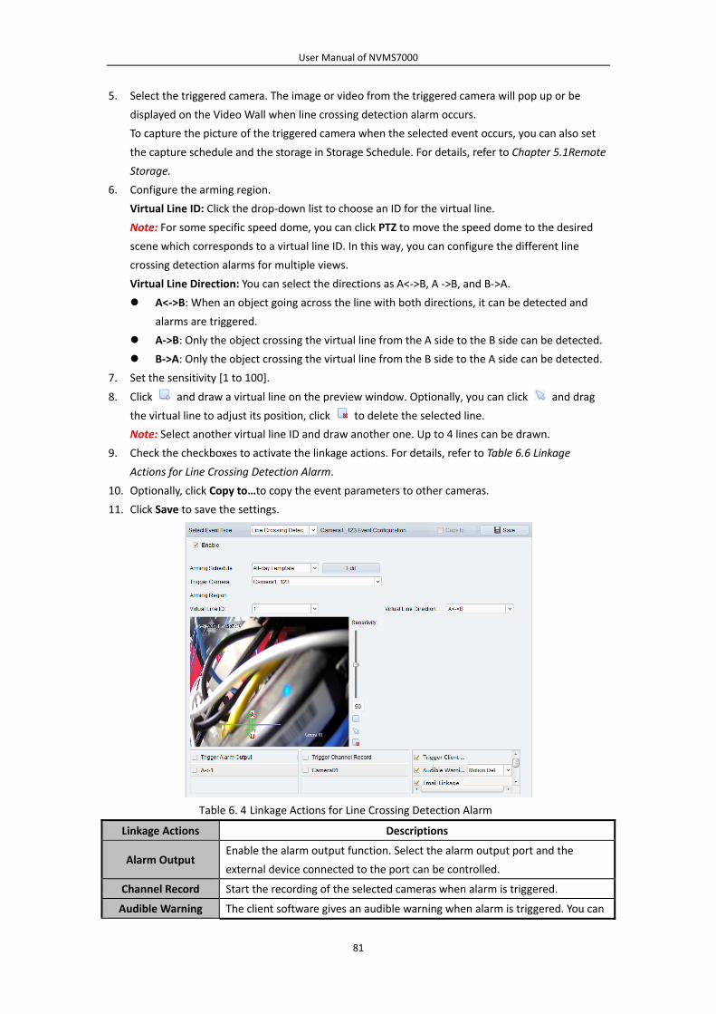
User Manual of NVMS7000
81
5. Select the triggered camera. The image or video from the triggered camera will pop up or be
displayed on the Video Wall when line crossing detection alarm occurs.
To capture the picture of the triggered camera when the selected event occurs, you can also set
the capture schedule and the storage in Storage Schedule. For details, refer to Chapter 5.1Remote
Storage.
6. Configure the arming region.
Virtual Line ID: Click the drop‐down list to choose an ID for the virtual line.
Note: For some specific speed dome, you can click PTZ to move the speed dome to the desired
scene which corresponds to a virtual line ID. In this way, you can configure the different line
crossing detection alarms for multiple views.
Virtual Line Direction: You can select the directions as A<‐>B, A ‐>B, and B‐>A.
A<‐>B: When an object going across the line with both directions, it can be detected and
alarms are triggered.
A‐>B: Only the object crossing the virtual line from the A side to the B side can be detected.
B‐>A: Only the object crossing the virtual line from the B side to the A side can be detected.
7. Set the sensitivity [1 to 100].
8. Click and draw a virtual line on the preview window. Optionally, you can click and drag
the virtual line to adjust its position, click to delete the selected line.
Note: Select another virtual line ID and draw another one. Up to 4 lines can be drawn.
9. Check the checkboxes to activate the linkage actions. For details, refer to Table 6.6 Linkage
Actions for Line Crossing Detection Alarm.
10. Optionally, click Copy to…to copy the event parameters to other cameras.
11. Click Save to save the settings.
Table 6. 4 Linkage Actions for Line Crossing Detection Alarm
Linkage Actions Descriptions
Alarm Output Enable the alarm output function. Select the alarm output port and the
external device connected to the port can be controlled.
Channel Record Start the recording of the selected cameras when alarm is triggered.
Audible Warning The client software gives an audible warning when alarm is triggered. You can

User Manual of NVMS7000
82
select the alarm sound for audible warning. For setting the alarm sound,
please refer to Chapter 17.2.7Alarm Sound Settings.
Email Linkage Send an email notification of the alarm information to one or more receivers.
Alarm on E‐map Display the alarm information on the E‐map.
Alarm Triggered
Pop‐up Image The image of the triggered camera pops up when alarm is triggered.
Alarm Triggered
Video Wall Display Display the video on the Video Wall when alarm is triggered.
6.5 Configuring Alarm Input Linkage
Purpose:
When a device's alarm input port receives a signal from an external alarm device, such as smoke
detector, doorbell, etc., the alarm input linkage actions are triggered for notification.
Before you start:
Add the alarm inputs to the client, click Import on the Group Management interface, click the Alarm
Input tab and import alarm inputs into groups for management.
Steps:
1. Open the Event Management page and click the Alarm Input tab.
2. Select the alarm input channel to be configured.
3. Check the checkbox Enable.
4. Input a descriptive name of the alarm.
5. Set the alarm status according to the alarm input device.
6. Select the arming schedule template from the drop‐down list.
If you need to edit or customize the template, refer to Configuring Arming Schedule Template.
7. Select the triggered camera. The image or video from the triggered camera will pop up or be
displayed on the Video Wall when alarm input occurs.
To capture the picture of the triggered camera when the selected event occurs, you can also set
the capture schedule and the storage in Storage Schedule. For details, refer to Chapter 5.1Remote
Storage.
8. Check the checkboxes to activate the linkage actions. For details, refer to Table 6.7 Linkage
Actions for Alarm Input.
9. Optionally, click Copy to…to copy the event parameters to other alarm inputs.
10. Click Save to save the settings.

User Manual of NVMS7000
83
Table 6. 5 Linkage Actions for Alarm Input
Linkage Actions Descriptions
Alarm Output Enable the alarm output function. Select the alarm output port and the
external device connected to the port can be controlled.
Channel Record Start the recording of the selected cameras when alarm is triggered.
Audible Warning
The client software gives an audible warning when alarm is triggered. You can
select the alarm sound for audible warning. For setting the alarm sound,
please refer to Chapter 17.2.7Alarm Sound Settings.
Email Linkage Send an email notification of the alarm information to one or more receivers.
Alarm on E‐map Display the alarm information on the E‐map.
Alarm Triggered
Pop‐up Image The image with alarm information pops up when alarm is triggered.
Alarm Triggered
Video Wall Display Display the video on the Video Wall when alarm is triggered.
6.6 Configuring Device Exception Linkage
Steps:
1. Open the Event Management page and click the Exception tab.
2. Select the device to be configured.
3. Select the device exception type, including HDD full, HDD exception, illegal login, device offline,
etc.
4. Check the checkbox Enable.
5. Check the checkboxes to activate the linkage actions. For details, refer to Table 6.8 Linkage
Actions for Device Exception.
6. Optionally, click Copy to…to copy the event parameters to other devices.
7. Click Save to save the settings.
Table 6. 6 Linkage Actions for Device Exception
Linkage Actions Descriptions
Alarm Output
Enable the alarm output function. Select the alarm output port and the
external device connected to the port can be controlled.
Note: Alarm Output is not available for Device Offline exception.
Audible Warning
The client software gives an audible warning when alarm is triggered. You can
select the alarm sound for audible warning. For setting the alarm sound,
please refer to Chapter 17.2.7Alarm Sound Settings.
Email Linkage Send an email notification of the alarm information to one or more receivers.

User Manual of NVMS7000
84
Chapter 7 Alarm and Event Center
Purpose:
The received recent alarms and events of all added devices can be displayed.
Note: Before you can receive the alarm information from the device, you need to click Tool‐>Device
Arming Control and arm the device by checking the corresponding checkbox. Then the alarm
information will be auto uploaded to the client software when alarm occurs.
Steps:
1. Click the icon in Alarms and Events Toolbar to show the Alarms and Events panel.
2. You can click to display the Alarm Event interface.
Or click icon on the control panel to enter the Alarm Event interface.

User Manual of NVMS7000
85
On the Alarms and Events panel, the following toolbar buttons are available:
Clear Info Clear the information of alarms and events displayed on the list.
Enable/Disable Alarm
Triggered Pop‐up Image Click to enable/disable image pop‐up when alarms occur.
Enable/Disable Audio Click to enable/disable the audio warning for the alarm.
Auto Hide/Lock Click to hide automatically/lock the Alarms and Events panel.
Maximize Maximize the Alarms and Events panel in a new tab page.
Show/Hide Click to show/hide the Alarms and Events panel.
7.1 Viewing Alarms Information
Purpose:
Different alarm types can be displayed on the panel: Motion Detection, Video/Audio Exception, Alarm
Input, Device Exception, VCA Alarm, CID Alarm, Access Control Alarm, and Other Alarm. You can check
the checkbox to enable the displaying of that type alarm.
Before you start:
To display the alarms, the event parameters need to be configured.
Steps:
1. Click the Alarm tab.
2. Check the checkboxes of different alarm types.
3. When an alarm occurs, the icon twinkles to call attention. The alarm information, including
the time, source, details and content will be displayed.
4. Click to get a live view of the alarm triggered camera.

User Manual of NVMS7000
86
You can view the live video of the triggered camera. You can click Prev Page or Next Page button
to view the previous or next alarm information.
Notes:
The Picture Storage should be checked for storing the alarm pictures of the camera on the
storage server. You can click Configure to set the parameters. For details, please refer to
Chapter 5.1.2Storing on Storage Device.
The Prioritize Display of Latest Alarm is unchecked by default.
You can check this checkbox to switch to view the latest triggered alarm. The alarm window
is in 4‐window division. The latest alarm will replace the earliest alarm window of the
displayed four windows.
5. Click to send an email notification of the alarm to one or more receivers if the email settings
are properly configured (Chapter 17.2.8Email Settings).
6. Click to display the video of alarm triggered camera on the Video Wall. You can enter the
Video Wall interface to check the alarm triggered video playing on the screen which set as the
alarm window. The physical video wall also displays the video.
Note: You should add decoding device and configure the video wall. For details, please refer to
Chapter 11 Decoding and Displaying Video on Video Wall.
Click under the Note column to input the description for the alarm.
7. To clear the alarm information, click the icon ,or right‐click on an alarm log and then click
Clear.
7.2 Viewing Events Information
Purpose:
The abnormal events of the client software, such as the live view failure, device disconnection, can
also be displayed.
Steps:
1. Click the Event tab.
The event information, including the time and detailed description will be displayed.
2. To clear the event information, click the icon ,or right‐click on the event log and then click

User Manual of NVMS7000
87
Clear.
7.3 Viewing Pop‐up Alarm Information
After enabling the event linkage of Alarm Triggered Pop‐up Image, and enabling the Enable Alarm
Triggered Pop‐up Image function on the client, the alarm image will pop up when the corresponding
event/alarm is triggered.
You can view the live video of the triggered camera. In the right panel, the alarm picture displays.
Notes:
The Picture Storage should be checked for storing the alarm pictures of the camera on the
storage server. You can click Configure to set the parameters. For details, please refer to Chapter
5.1.2Storing on Storage Device.
The Prioritize Display of Latest Alarm is checked by default and the alarm window is in 4‐window
division. The latest alarm will replace the earliest alarm window of the displayed four windows.
You can uncheck this checkbox to switch to view the current triggered alarm. You can click Prev

User Manual of NVMS7000
88
Page or Next Page button to view the previous or next alarm information.

User Manual of NVMS7000
89
Chapter 8 E‐map Management
Purpose:
The E‐map function gives a visual overview of the locations and distributions of the installed cameras,
alarm input devices, zones, and access control points. You can get the live view of the cameras on the
map, and you will get a notification message from the map when alarm is triggered. You can also
control the access control points on the E‐map such as opening and closing door.
Click the icon on the control panel,
or click View‐>E‐map to open the E‐map page.
E‐map Page
1 Group List
2 Map Display Area
3 E‐map Toolbar
8.1 Adding an E‐map
Purpose:
An E‐map needs to be added as the parent map for the hot spots and hot regions.
Steps:
1. Open the E‐map page.
2. Select a group for which you want to add a map.
3. Click the icon in the Map Display Area to open the map adding dialog box.
4. Input a descriptive name of the added map as desired.
5. Click the icon and select a map file from the local path.
6. Click OK to save the settings.
Notes:
The picture format of the map can only be *.png, *.jpg or *.bmp.
Only one map can be added to a group.

User Manual of NVMS7000
90
The map added is displayed in the Map Display Area. Use the mouse wheel or click or , to
zoom in or zoom out on the map. You can click‐and‐drag the yellow window in the lower‐right corner
or use the direction buttons and zoom bar to adjust the map area for view.
Click the button Edit Map or Map Preview in the E‐map toolbar to enter the map editing mode or
map preview mode.
E‐map Toolbar in Map Editing Mode:
E‐map Toolbar in Map Preview Mode:
On the E‐map page, the following toolbar buttons are available:
Modify Map Modify the map information, including the map name and file path.
Delete Map Delete the current map.
Add Camera Add a camera as the hot spot on the map.
Add Alarm Input Add an alarm input sensor as the hot spot on the map.
Add Access Control Point Add an access control point as the hot spot on the map.
Add Zone Add a zone as the hot spot on the map.
Add Hot Region Add a map as the hot region on the current map.
Modify Modify the information of the selected hot spot or hot region.
Delete Delete the selected hot spot or hot region.

User Manual of NVMS7000
91
Clear Alarm Info Clear the alarm information displayed on the map.
Back to Parent Map Go back to the parent map.
8.2 The Hot Spot Function
Purpose:
The cameras and alarm inputs can be added on the map and are called the hot spots. The hot spots
show the locations of the cameras and alarm inputs, and you can also get the live view and alarm
information of the surveillance scenarios through the hot spots.
Notes:
For managing and previewing the access control point hot spot, please refer to Chapter
13.9Displaying Access Control Point on E‐map.
For managing and previewing the zone hot spot, please refer to Chapter 12.3Displaying Zone on
E‐map.
8.2.1 Adding Hot Spots
Adding Cameras as Hot Spots
Steps:
1. Click the Edit Map button in the E‐map toolbar to enter the map editing mode.
2. Click the icon in the toolbar to open the Add Hot Spot dialog box.
3. Check the checkboxes to select the cameras to be added.
4. Optionally, you can edit hot spot name, select the name color and select the hot spot icon by
double‐clicking the corresponding field.
5. Click OK to save the settings. The camera icons are added on the map as hot spots and the icons
of added cameras changes from to in the group list. You can click‐and‐drag the camera
icons to move the hot spots to the desired locations.
You can also click‐and‐drag the camera icons from the group list to the map directly to add the
hot spots.

User Manual of NVMS7000
92
Adding Alarm Inputs as Hot Spots
Steps:
1. Click the Edit Map button in the E‐map toolbar to enter the map editing mode.
2. Click the icon in the toolbar to open the Add Hot Spot dialog box.
3. Check the checkboxes to select the alarm inputs to be added.
4. Optionally, you can edit hot spot name, select the name color and select the hot spot icon by
double‐clicking the corresponding field.
5. Click OK to save the settings. The alarm input icons are added on the map as hot spots and the
icons of added alarm inputs changes from to in the group list. You can click‐and‐drag the
alarm input icons to move the hot spots to the desired locations.
You can also click‐and‐drag the alarm input icons from the alarm input list to the map directly to
add the hot spot.
8.2.2 Modifying Hot Spots
Purpose:
You can modify the information of the added hot spots on the map, including the name, the color, the
icon, etc.
Steps:
1. Click the Edit Map button in the E‐map toolbar to enter the map editing mode.
2. Select the hot spot icon on the map and then click in the toolbar, right‐click the hot spot icon
and select Modify, or double‐click the hot spot icon on the map to open the Modify Hot Spot
dialog box.
3. You can edit the hot spot name in the text field and select the color, the icon and the linked
camera or alarm input.
4. Click OK to save the new settings.
To delete the hot spot, select the hot spot icon and click in the toolbar, or right‐click the hot
spot icon and select Delete.

8.2
Step
1.
2.
3.
Note
as th
8.3
Purp
The
2.3 Prev
ps:
Click the Map
Double‐click t
view of the ca
If there is any
twinkle for 10
alarm type an
e: To display t
he alarm linka
3 The
pose:
hot region fun
viewing H
p Preview but
the camera ho
ameras.
y alarm trigge
0s). Click the a
nd triggering t
he alarm infor
ge action.For
e Hot Re
nction links a
User M
Hot Spots
tton in the E‐m
ot spots or rig
red, an icon
alarm icon, an
time.
rmation on th
details, refer
egion F
map to anoth
Manual of NVM
93
s
map toolbar to
ght‐click it and
will appear
nd then you ca
he map, the A
toChapter 6 E
Functio
her map. Whe
MS7000
o enter the m
d select Live V
r and twinkle
an check the a
larm on E‐ma
Event Manage
on
en you add a m
ap preview m
View, and you
near the hot s
alarm informa
p functionalit
ement.
map to anothe
mode.
can get the liv
spot (it will
ation, includin
ty needs to be
er map as a ho
ve
g
e set
ot

User Manual of NVMS7000
94
region, an icon of the link to the added map is shown on the main map. The added map is called child
map while the map to which you add the hot region is the parent map.
Note: A map can only be added as the hot region for one time.
8.3.1 Adding Hot Regions
Before you start:
Add a map to another group.
Steps:
1. Click the Edit Map button in the E‐map toolbar to enter the map editing mode.
2. Select an added map as the parent map.
3. Click the icon in the toolbar to open the Add Hot Region dialog box.
4. Check the checkbox to select the child map to be linked.
5. Optionally, you can edit the hot region name, and select the hot region color and icon by
double‐clicking the corresponding field.
6. Click OK to save the settings. The child map icons are added on the parent map as the hot regions.
You can click‐and‐drag the child map icons to move the hot regions to desired locations.
8.3.2 Modifying Hot Regions
Purpose:
You can modify the information of the hot regions on the parent map, including the name, the color,
the icon, etc.
Steps:
1. Click the Edit Map button in the E‐map toolbar to enter the map editing mode.
2. Select the hot region icon on the parent map and then click in the toolbar, right‐click the hot
spot icon and select Modify, or double‐click the hot region icon to open the Modify Hot Region
dialog box.
3. You can edit the hot region name in the text field and select the color, the icon and the linked
child map.
4. Click OK to save the new settings.
To delete the hot region, select the hot region icon and click in the toolbar, or right‐click the
hot spot icon and select Delete.

User Manual of NVMS7000
95
8.3.3 Previewing Hot Regions
Steps:
1. Click the Map Preview button in the E‐map toolbar to enter the map preview mode.
2. Click the hot region icon to go to the linked child map.
3. The hot spots can also be added on the hot regions.
4. You can click the icon in the toolbar to go back to the parent map.
You can also click the icon in the toolbar to clear the alarm information.

Purp
The
and
9.1
Purp
If yo
Step
1.
2.
3.
4.
pose:
client softwar
manage the d
1 Reg
pose:
u do not have
ps:
Open the Dev
Click Add New
Click Guardin
Enter the req
Guarding Vis
Password and
Email: Enter y
Verification C
Refresh to ge
Email Verifica
your email.
For your
choosing
numbers
Proper co
installer
Chap
re also suppor
devices which
gistering
e aGuarding V
vice Managem
w Device Type
ng Vision Devi
uired informa
ion Account:
d Confirm: En
your email acc
Code: Enter th
et a new one.
ation Code: C
privacy, we st
g (using a min
s, and special
onfiguration o
and/or end‐us
User M
pter 9
rts to register
support the G
g a Gua
Vision account
ment page and
e, select Guar
ice on the list
ation to registe
Edit a user na
nter the passw
count to regis
he verification
lick Get Verifi
trongly recom
imum of 8 cha
characters) in
of all passwor
ser.
Manual of NVM
96
Guar
a Guarding V
Guarding Visio
arding
, you can regi
d click the Dev
rding Vision D
and then click
er an account
ame for your a
word for your a
ster the accou
code shown
ication Code a
mmend changi
aracters, inclu
n order to incre
rds and other s
MS7000
ding V
ision account,
on service.
Vision
ster one.
vice tab.
Device and clic
k Register.
t.
account as des
account and c
nt.
in the picture
and enter the
ing the passwo
uding upper ca
ease the secu
security settin
Vision
, log into your
Accou
ck OK.
sired.
confirm it.
e. If it is not cle
verification c
ord to someth
ase letters, low
rity of your pr
ngs is the resp
r Guarding Vis
nt
ear, you can c
ode received
hing of your o
wer case lette
roduct.
ponsibility of th
sion
lick
by
wn
ers,
he

5.
9.2
Step
1.
2.
3.
4.
9.3
Step
1.
Click Register
2 Logg
ps:
Click Login.
Enter the Gu
Click Login to
Notes:
The sof
If you fo
passwo
Guardin
Security
Refresh
Email V
receive
Passwo
it.
For your
choosing
numbers
Proper co
installer
After login, y
Guarding Vis
3 Dev
ps:
Click Add De
Notes:
r to get aGuar
ging in
uarding Vision
o log into you
ftware will log
orget your pas
ord.
ng Vision Acco
y Code: Enter
h to get a new
Verification Co
d by your ema
ord and Confir
privacy, we st
g (using a min
s, and special
onfiguration o
and/or end‐us
you can click L
sion account.
vice Ma
evice and inpu
User M
rding Vision ac
to Gua
account and
r account.
gin the Guardi
ssword, click F
ount: Edit use
r the security c
w one.
ode: Click Get
ail.
rm: Click Next
trongly recom
imum of 8 cha
characters) in
of all passwor
ser.
Login to switch
anagem
ut the serial N
Manual of NVM
97
ccount.
arding V
password.
ng Vision acco
Forgot Passwo
er name of yo
code shown in
Verification C
t and enter a n
mmend changi
aracters, inclu
n order to incre
rds and other s
h to another a
ment
o. and verifica
MS7000
Vision A
ount automat
ord to verify y
ur account.
n the picture.
Code and ente
new password
ing the passwo
uding upper ca
ease the secu
security settin
account or clic
ation code of
Accoun
tically next tim
your account a
If it is not cle
er the verifica
d for your acco
ord to someth
ase letters, low
rity of your pr
ngs is the resp
ck Logout to l
the device.
nt
me.
and reset you
ar, you can cli
ation code
ount and conf
hing of your o
wer case lette
roduct.
ponsibility of th
og out of you
ur
ick
firm
wn
ers,
he
r

User Manual of NVMS7000
98
Only the device that supports the Guarding Vision service can be added.
The serial No. and the verification code is marked on the label of you device.
The device can only be added to one Guarding Vision account.
2. Click OK to add the device and the successfully added device will list on the device management
interface.
Note:A group named as your account name is created by default, you can import the cameras of
the added devices to the default group or other groups. For group management, please refer
toChapter 3.2Group Management.
3. Click to select a device and click Config to pop up the remote configuration interface of the
device.You can do some remote configurations for the device. For detailed settings about the
remote configuration, please refer to the User Manual of the device.
Note: This function should be suported by the device.
4. If you want delete the device, select the device(s) and click Delete Device. You can also enter the
keyword of the device name in the Filter field to filter the required devices.

User Manual of NVMS7000
99
Chapter 10 Forwarding Video Stream through
Stream Media Server
Purpose:
There is always a limit of the device remote access number. When there are many users wanting to get
remote access to the device to get the live view, you can add the stream media server and get the
video data stream from the stream media server, thus to lower the load of the device.
10.1 Adding the Stream Media Server
Before you start:
The stream media server application software needs to be installed and it is packed in the
NVMS7000software package. When installing the NVMS7000, check the checkbox Stream Media
Server to enable the installation of stream media server.
Steps:
1. Click the shortcut icon on the desktop to run the stream media server.
Notes:
You can also forward the video through the stream media server installed on other PC.
If the stream media server port (value: 554) is occupied by other service, a dialog box will
pop up. You should change the port No. to other value to ensure the proper running of the
stream media server.
2. Open the Device Management page and click the Device tab.
3. Click Add New Device Type, select Stream Media Server and click OK.
4. Click Stream Media Server on the list and then click Add.
You can add the stream media server in the following two ways:
Adding Stream Media Server by IP Address
Perform the following steps to add the stream media server:
1) Select IP Address as the adding mode.
2) Input the nickname and IP address of the stream media server. The default port value is
554.
3) Click Add to add the stream media server to the client software.
Adding Stream Media Server by IP Segment
Perform the following steps to add the stream media server by IP segment:
1) Select IP Segment as the adding mode.

User Manual of NVMS7000
100
2) Input the start IP and end IP. The default port value is 554.
3) Click Add to add the stream media server to the client software. The steam media
server of which the IP address is between the start IP and end IP will be added to the
client.
Note: For one client, up to 16 stream media servers can be added.
10.2 Adding Cameras to Stream Media Server to
Forward Video Stream
Purpose:
To get the video stream of a camera via stream media server, you need to connect the camera to the
stream media server.
Steps:
1. Select the stream media server from the list.
2. Click Configure to enter the Stream Media Server Settings interface.
3. Select the cameras of which the video stream is to be forwarded via the stream media server.
4. Click OK to save the new settings.
5. Go the Main View page and start the live view of the cameras again. You can check the channel
number of the video stream forwarded through or sent from the stream media server.
Notes:
For one stream media server, up to 64 channels of video stream can be forwarded through it and
up to200 channels of video stream can be sent to clients from it.
If the camera is offline, the client can still get the live video via the stream media server.

User Manual of NVMS7000
101
Chapter 11 Decoding and Displaying Video on
Video Wall
Purpose:
The Video Wall module provides the video decoding functionality, and the decoded video can be
displayed on the Video Wall for an attention‐grabbing performance.
Click the icon on the control panel, or click View‐>Video Wall to open the Video Wall page.
11.1 Adding the Encoding Device
Purpose:
You should add the encoding device for decoding and displaying on the video wall. If you do not add
the encoding devices in the Device Management page, you can add them in Video Wall page.
Steps:
1. In the Camera area, click to activate the adding device window.
2. Select the adding mode and configure the corresponding settings for the device.
For the detailed configuration about the 4 adding modes, please refer to the following chapters:

User Manual of NVMS7000
102
By specifying the device IP address, refer toChapter3.1.3Adding Devices by IP or Domain
Name.
By specifying an IP segment, refer toChapter3.1.4Adding Devices by IP Segment.
By IP Server, refer toChapter3.1.8Adding Devices by IP Server.
By HiDDNS, refer toChapter3.1.9Adding Devices by HiDDNS.
(Optional) If you want to add the third‐party encoding device, please perform the following steps:
Steps:
1. Go to the Device Management page and click the Device tab.
2. Click Add New Device Type, select Third‐party Encoding Device and click OK.
3. Select Third‐party Encoding Device in the device type panel and click Add to activate the Add
Device window.
For IP/Domain: Edit the nickname, IP address/domain name, port No., user name, password,
channel number, start from and protocol for the device.
For IP Segment: Edit the start IP, end IP, port No., user name, password, channel number,
start from and protocol for the device.
Example: If you input 4 in Start From field, it means that the starting channel No. is 4.
11.2 Adding the Decoding Device
Purpose:
To decode the video of the encoding device and display the decoded video on the Video Wall, the
decoding device needs to be added to the client.
Steps:
1. Click Enter Video Wall Config to enter the decoding device and video wall configuration interface.
2. In the Decoding Output area, click to activate the Quick Adding of Decoding Device window.

User Manual of NVMS7000
103
3. There are two adding modes available. Select the adding mode and configure the corresponding
settings for the device.
For the detailed configuration about the two adding modes, please refer to the following
chapters:
By specifying the device IP address or domain, refer to Chapter 3.1.3Adding Devices by IP or
Domain Name.
By specifying an IP segment, refer toChapter3.1.4Adding Devices by IP Segment.
Edit the Output of the Decoding Device
Steps:
1. In the Decoding Output area, click before the decoding device to list the outputs of it.
2. Double‐click an output and you can edit the parameters for it. Or you can right‐click a decoding
output in the video wall area and select Decoding Output Configuration to edit its parameters.
Note: For HDMI and VGA outputs, the resolution can be configured; for BNC output, the video
standard can be configured.
3. (Optional) you can check the checkbox of Batch Configuration and select other outputs to copy
the settings to.
4. Click OK to save the settings.
Notes:
With the extension HDMI output board, NVR also supports decoding function:

User Manual of NVMS7000
104
It can link with the video inputs and display them on the video wall without through decoding
device.
It can realize the video wall display, windowing and roaming of images of the cameras directly via
the HDMI outputs.
You can also edit the parameters of the decoding output.
For details, please refer to the User Manual of the NVR.
11.3 Configuring Video Wall Settings
Purpose:
After the encoding device and decoding device have been added, the parameters of Video Wall need
to be configured for video display.
11.3.1 Linking Decoding Output with Video Wall
Steps:
1. Click Enter Video Wall Config to enter the decoding device and video wall configuration interface.
2. A default video wall view with the window division of4*4 is provided. You can edit the default
video wall or add a new video wall as desired.
Task 1: Add a Video Wall
1) Right‐click the video wall and select Add Video Wall, or click to activate the Add Video
Wall window.
2) Enter the name, row number, column number and proportion of the video wall.
3) Click Add.
Task 2: Edit a Video Wall
1) Right‐click the video wall and select Modify Video Wall to edit it.
2) In the pop‐up window, you can edit the name, row number, column number and proportion

User Manual of NVMS7000
105
of the video wall.
Note: You can also drag your mouse to set the needed video wall.
3) Click Modify to save the settings.
Task 3: Delete a Video Wall
To delete the video wall, right‐click the video wall and select Delete Video Wall, or click of
the video wall.
3. Click‐and‐drag the decoding output on the left‐side list to the display window of video wall, to
configure the one‐to‐one correspondence. You can also click and hold the Ctrl or Shift key to
select multiple outputs and then drag them to the video wall for configuring linkage in batch. You
can click in the upper‐right corner of the display window to release the linkage.
Notes:
Up to 4 video walls can be added to the client software.
The total number of the display windows of the video wall should be no more than 100.
The ranges of the row number and column number are both between 1 and 10.
11.3.2 Multi‐Screen Display
Purpose:
For DS‐6400HDI‐Tseries and DS‐6900UDI series decoder, you can joint multiple screens as a whole
window. In this way, the decoded video of one camera can be shown on the jointed window.
Before you start:
You should add DS‐6400HDI‐T series and DS‐6900UDI series decoding device to the client. Please refer
to Chapter11.2Adding the Decoding Device for detailed configuration about adding decoding device.
Steps:
1. Perform the step 3 of Chapter11.3.1Linking Decoding Output with Video Wall to configure the
linkage between the decoder and video wall.
2. Click‐and‐drag you mouse to select the adjacent display windows for jointing.
Notes:
You can only joint the same output interfaces as a whole window. E.g., you can only joint 4
VGA interfaces or HDMI interfaces.
BNC interface does not support jointing.

User Manual of NVMS7000
106
3. Click to confirm jointing the screens.
4. (Optional) You can set the resolution for the jointed window by right‐clicking on it and select
Decoding Output Configuration.
To cancel the multi‐screen display, click in the upper‐right corner of the display window.
11.3.3 Configuring Background
Purpose:
You can upload pictures for showing as the background of the video window.
Note: The function should be supported by the decoding device.
Steps:
1. Click to expand the Background Picture panel.
2. Select a background picture and double‐click (or right‐click and select Background Configuration)
it to activate the background uploading window.

User Manual of NVMS7000
107
3. Set a user‐defined name for the background picture and click to select a picture file.
4. Click Upload to upload the picture.
5. Click and drag the configured background picture to the desired position of the video wall.
6. You can move the window when the cursor becomes and adjust its size when the cursor
becomes directional arrow. Right‐click on the background picture and select Show or Hide to
show or hide the background picture.
Note: The picture will be displayed on the physical video wall after you upload the background.
11.3.4 Configuring Virtual LED
Purpose:
You can display the required contents on the video wall by using virtual LED.
Note: The function should be supported by the decoding device.
Steps:
1. Click Enter Video Wall Config to enter the configuration interface.
2. Click to display the Virtual LED panel, click to expand the added decoding device.
3. Click‐and‐drag the virtual LED to the video wall.
4. You can move the window when the cursor becomes and adjust its size when the cursor
becomes directional arrow.
5. Right‐click the virtual LED in the panel and select Virtual LED Settings to set the parameters for it.
Content: Set the content that you want to display on the video wall.
Show Mode: Select the mode of the virtual LED as desired.
Moving Mode: Set the scrolling effect for the displayed text.
Moving Direction: Set the scrolling direction for the displayed text.
Moving Speed: Set the moving speed for the displayed text.
Font Size: Set the size of the displayed text.
Font Color: Set the color of the displayed text by clicking Color.
Background Color: Set the color of the background by clicking Color

User Manual of NVMS7000
108
11.4 Displaying Video on Video Wall
Purpose:
After the settings of the encoding device, decoding device and video wall, the video stream from the
encoding devices can be decoded and displayed on the Video Wall.
Notes:
After enable decoding and displaying, the captured picture of the video from the encoding
device displays on the Video Wall interface. And the real‐time live view is shown on the physical
video wall.
For some kinds of decoder, the video stream from the signal source (which refers to the video
signal (e.g., PC) connected to the decoder via the local interfaces) can also be displayed on the
video wall. For detailed configuration, please refer to the User Manual of the device.
11.4.1 Decoding and Displaying
Steps:
1. Click Back to Operation Page to go back to the Video Wall Operation interface.
2. Click to save the linkage settings for the current scene. Or click (beside ) and select a
scene to save the settings for.
Notes:
8 scenes can be set for a video wall. Each scene can be configured with different linkage
settings and window divisions.
For editing the name of a scene, select a scene and click to define a new name for it. You
can also click to clear all the settings for the scene.
3. Select a scene which is configured with linkage settings and click to enable the scene.
4. Click‐and‐drag the camera on the left‐side list to the display window of video wall. The video
stream from the camera will be decoded and displayed on the Video Wall. You can also select a
decoding window and then double‐click a camera to decode and display the video. You can also
click and hold the Ctrl or Shift key to select multiple cameras and then drag them to the video
wall.
Note: For DS‐6400HDI‐T and DS‐6900UDI decoder, you can select the signal source on the Signal

User Manual of NVMS7000
109
Source panel for video wall display.
5. Select a playing window and click the icon to get a preview of the video in the lower‐right
corner of the screen. Or you can directly drag a camera to the preview window for live view. You
can also double‐click the preview window to get a full‐screen view.
Note: You can move the mouse to the window and click in the lower‐right corner to
stopdecoding.
6. (Optional) Select a decoding window and click to set the window division for it. Click to
save the settings for the current scene. Or click (beside ) and select a scene to save the
settings for.
7. If the decoded camera supports PTZ control, you can click beside PTZ to activate the PTZ
control panel. For detailed configuration, please refer to Chapter4.3PTZ Control in Live View.
8. Right‐click on a playing window to activate the decoding management menu, as shown below:
Note: The menu differs depending on the devices.
Stop/Start Decoding: Stop/Start the decoding.
Start/Pause Successive Decoding: Start/Pause the cycle decoding.This function is only supported by
decoder.
Refresh: Refresh the decoding.
Open/Close Digital Zoom: Enable/Disable digital zoom.
Enable Audio: Turn on/off the audio of the decoding video.
Enlarge Window: Display the window in full‐screen mode.
Decoding Channel Status: View the status of the decoding channel, such as decoding status, stream
type.
Upload Logo: Upload a picture as the logo to the video window and set the display parameters for it.
After setting, the logo shows in the defined position of the window on physical video wall.
Show/Hide Logo: Show/Hide the logo.
Stick on Top: Always stick the window on the top layer.
Stick at Bottom: Always stick the window at the bottom layer.
Lock: Lock the window to disable the roaming function.
Set Alarm Window: Display the video triggered by event or alarm input on Video Wall.
Decoding Delay: Set the delay degree of the decoding according to the actual needs.
Go to Playback: Enter the playback mode. This function is only supported by decoder.

User Manual of NVMS7000
110
Icon Description
Start all the decoding
Stop all the decoding
Stop all the roaming windows
Refresh all the decoding windows
Set cycle decoding and switching interval
11.4.2 Windowing and Roaming Settings
Purpose:
Windowing is to open a new window on the screen(s).The window can be within a screen or span
multiple screens. You can move the playing window within the video wall as desired and this function
is called roaming.
Note: The windowing and roaming function should be supported by the decoding device.
Steps:
1. Click‐and‐drag on a screen which links to a decoding output to open a window. The window can
be within a screen or span multiple screens. If you want to open a window on the opened window,
click‐and‐drag and hold the Ctrl key to create one. And for the locked window (refer to step 6),
you can click‐and‐drag to create a new window on it.
Note: At least one camera should be selected before opening window.

User Manual of NVMS7000
111
2. You can move the window when the cursor becomes and adjust its size when the cursor
becomes directional arrow. You can also hold the Shift key to scale the window in proportion.
3. During moving the window, the dotted borders will display. The window will be adjusted to align
with the borders if it is moved to the location near the dotted borders.
4. Double‐click the window and it will enlarge to fill the spanning screens and display on the top
layer. You can double‐click again to restore.
5. (Optional) Select a window and click to set the window division for it. Click to save the
settings for it.
6. Right‐click on a window and select Lock in the right‐click menu to disable the roaming function,
and the icon shows on the top‐right corner of the window. In this way, the window cannot be
moved and resized. You can right‐click on the window and select Unlock in the right‐click menu to
recover the roaming function.
7. Right‐click on a window and select Stop Decoding in the right‐click menu, or move the mouse to
the window and click in the upper‐right corner to stop the decoding of the window and it will
be closed. You can also click to close all the roaming windows.
8. The window only shows a captured picture of the decoded video. You can right‐click on a window
and select Refresh in the right‐click menu, or move the mouse to the window and click in the
lower‐right corner to capture a latest picture of the decoded video and display on the window.
9. If you want to view the specific area of the video in details, you can right‐click on a window and
select Open Digital Zoom(if available)in the right‐click menu and the cursor becomes . Use the
mouse to drag on the video to realize digital zoom. You can check the effect on the physical video
wall
10. Select a playing window and click the icon to get a preview of the video in the lower‐right
corner of the screen. Or you can directly drag a camera to the preview window for live view. You
can also double‐click the preview window to get a full‐screen view.
11. Right‐click on a playing window and you can control decoding management via the right‐click
menu.

User Manual of NVMS7000
112
11.4.3 Configuring Playback
Purpose:
The video file is supported to be played back on the video wall.
Note: Playback function is only supported by decoder.
Steps:
1. Click‐and‐drag the camera on the left‐side list to the display window of video wall, or you can
open a window if supported.
2. Move the mouse to the window and click in the upper‐right corner. Or you can right‐click on
the window and select Go to Playback in the right‐click menu.
3. If there is video file of current day, the video file will be played back automatically. If not, you can
set the search condition on the search panel which shows in the left area of the interface (click
to show more search options, and then click the icon to specify the start time and end time
for the search), and click Search to find the video file.
4. Right‐click on the playback window and you can control the playback through the right‐click menu,
such as pause, stop, fast forward, slow forward, capture, start recording and full‐screen playback.
Note: The saving path for the captured pictures and recorded files can be configured on System
Configuration page. Please refer to Chapter17.2.4File Saving Path Settings for detailed settings.
When you move the mouse to the screen, the icons will display as shown below.
Icon Description
Pause the playback
Stop the playback
Capture the playback video
Record the playback video
Back to live view mode
Playback speed.

User Manual of NVMS7000
113
11.4.4 Configuring Cycle Decoding
Purpose:
The cycle decoding refers that you can configure multiple video streams of encoding devices to one
decoding output and you can set the switching interval for the decoding.
Note: The cycle decoding is only supported by decoder.
Steps:
1. Click beside and set the switching interval for the cycle decoding.
2. Click‐and‐drag the camera on the left‐side list to the display window of video wall, or you can
open a window if supported.
Note: The cycle decoding is not supported by the signal source of DS‐6400HDI‐T and DS‐6900UDI.
3. Move the mouse to the group node and click to start cycle decoding (the decoding output
under cycle decoding will be marked with ). Right‐click on the window and you can control
decoding management via the right‐click menu.

User Manual of NVMS7000
114
Chapter 12 Security Control Panel
Purpose:
The Security Control Panel module provides remote control and configuration via the NVMS7000
client software.
Note: For the users with security control panel permissions, they can enter the Security Control Panel
module to manage the security control panel and real‐time alarm. For setting the user permission of
Security Control Panel module, refer to Chapter 17.1Account Management.
Before you start:
Before you can remotely configure and control the security control panel, you should add device to
the software. For details about adding security control panel, refer to Chapter 3.1Adding the Device.
12.1 Configuring Zone Event
Purpose:
You can configure the event linkages, including siren, relay, client linkage and triggered cameras, for
the zones of the security control panel.
Note: The zone should be disarmed before configuring the zone event linkages.
Steps:
1. Click on the Control Panel, or click Tool‐>Event Management to open the Event
Management page.
2. Click the Zone Event tab.
3. Click the icon to unfold the zone list of a security control panel on the left panel.
4. Click a zone name on the list to activate the configuration of the zone event.
5. Configure the name, type and event linkages for the zone.
1) Edit the zone name in the Zone Name field.
2) Unfold the drop‐down list of the Zone Type field and select a type.

User Manual of NVMS7000
115
3) Check the checkbox(es) to select the linked relay(s) on the Linked Relay panel.
4) Check the checkbox(es) to select the linked siren(s) on the Linked Siren panel.
5) Check the checkbox(es) to activate the linkage action(s) on the Trigger Client Action panel.
See the detailed actions below:
Linkage Actions Descriptions
Audible Warning
The client software gives an audible warning when alarm is triggered.
You can select the alarm sound for audible warning. For setting the
alarm sound, refer to Chapter 17.2.7Alarm Sound Settings.
Email Linkage Send an email notification of the alarm information to one or more
receivers.
Alarm on E‐map Display the alarm information on the E‐map.
Alarm Triggered
Pop‐up Image The image with alarm information pops up when alarm is triggered.
Alarm Triggered
Video Wall Display Display the video on the Video Wall when alarm is triggered.
6) Select the camera(s) on the Trigger Camera panel to be triggered for popping up image or
displaying on the video wall when the alarm is triggered.
To capture the picture of the triggered camera when the selected event occurs, you should
set the capture schedule and the storage in Storage Schedule. For details, refer to Chapter
5.1Remote Storage.
Note: Up to 4 cameras can be set as the triggered cameras.
6. Optionally, click Copy to…to copy the event settings to other zones.
7. Click Save to save the settings.
12.2 Remote Control
Purpose:
In this section, you can control the security control panel remotely to perform operations such as
arming, disarming, bypass, group bypass, and so on for both the partitions and zones.
Click on the Control Panel, or click View‐>Security Control Panel to open the Security Control Panel
page.

User Manual of NVMS7000
116
You can check the checkbox(es) of Network Security Control Panel, Video Security Control Panel, or
Panic Alarm Station to display the security control panels by type.
Or you can input the keyword on the search field to search the desired panels.
Click Refresh to update the status of security control panels.
12.2.1 Display Mode
Purpose:
The Security Control Panel module provides two display modes for showing the added security control
panel, including list mode and tile mode.
By default, the panels are shown in list mode. You can click the icon or at the upper right
corner of the page to switch the display mode between the tile or list mode.
List Mode
Click the icon , and the security control panels will display in list on the left panel of the page.
And you can click the panel name in the list to show the details of the device’s partitions and zones on
the right panel.

User Manual of NVMS7000
117
Tile Mode
Click the icon , and the security control panels will tile with the icons, types, names, partitions and
zones on the page. You can click to view different partitions.
12.2.2 Partition Remote Control
Purpose:
You can remotely perform operations of away arming, stay arming, instant arming, disarming, clearing
alarm, group bypass, and recovering group bypass for the configured partitions.
Steps:
1. Click Operation (list mode) or (tile mode) to pop up the Partition Operation window and

User Manual of NVMS7000
118
control the partitions in batch.
2. Check the checkbox(es) to select the partition(s), or check the All checkbox to select all the
partitions.
3. Click the operation button (e.g., Away Arming, Stay Arming, Instant Arming, Disarm, Clear Alarm,
Group Bypass or Group Bypass Recovery) to control the selected partition(s).
(Optional) You can click Cancel to cancel applying the operations and close the Partition
Operation window.
You can also click the icon in the Status column (list mode) or the area at the right of the partition
name (tile mode) on the Security Control Panel page to show the drop‐down list and select an
operation to control a single partition.
12.2.3 Zone Remote Control
Purpose:
You can remotely perform bypass, or recover bypass for the zones.
Steps:
1. Click View in the Linked Zone column (list mode) or the partition name (tile mode) to pop up
Zone Operation window.
You can view the all linked zones of the partition in this window and check the zone status.
Note: The icon will appear in the Status column on the left of the partition name if there is
fault zone in the partition or when the zone alarm is triggered. You can move the cursor to the
icon to view the detailed zone status. For the details about the triggered zone alarm, refer to
Chapter 12.4Handling Alarms.

User Manual of NVMS7000
119
2. Check the checkbox(es) to select the zone(s), or check the Zone No. checkbox to select all the
zones.
3. Click the Bypass or Bypass Recovery button on the upper left corner of the window to control
the selected zones.
4. Click the icon in the Live View column to view the live view of the triggered camera in the
zone.
Note: You can set the triggered camera of the zone in the Event Management module. For details,
refer to Chapter 12.1Configuring Zone Event.
12.3 Displaying Zone on E‐map
Purpose:
You can add the zones on the E‐map, and when the alarm in the zone is triggered, you can view the
alarm notification on the E‐map and check the alarm details.
Note: For detailed operations of E‐map, refer to Chapter 8 E‐map Management.
Adding Zones as Hot Spots
Steps:
1. In the E‐map module, click Edit Map tabat the lower left corner to enter the map editing mode.
2. Click the icon on the E‐map Toolbar to open the Add Hot Spot dialog.
Or you can directly drag the zone icons from the group list on the left panel of E‐map page to the
map to add the hot spots.

User Manual of NVMS7000
120
3. Check the checkbox(es) to select the zone(s) to be added.
Optionally, you can edit hot spot name, select the name color and select the hot spot icon by
double‐clicking the corresponding field.
4. Click OK to save the settings.
The zone icon(s) will be added to the map as hot spot(s) and the icon(s) of added zone(s) in the group
list of the left panel will change from to .
You can drag the zone icon to move the hot spot to the desired location.
Modifying Hot Spots
Purpose:
You can modify the information of the added hot spots on the map, including the name, the color, the
icon, etc.
Steps:
1. In the E‐map module, click the Edit Map tabat the lower left corner to enter the map editing
mode.
2. Select the hot spot icon on the map and then click in the E‐map Toolbar to open the Modify
Hot Spot dialog.
Or right‐click the hot spot icon on the map and select Modify in the right‐click menu to open the
Modify Hot Spot dialog.
Or double‐click the hot spot icon on the map to pop up the Modify Hot Spot dialog.

User Manual of NVMS7000
121
You can edit the hot spot name in the text field and select the color, the icon and the linked zone.
3. Click OK to save the settings.
To delete the hot spot, select the hot spot icon and click in the toolbar, or right‐click the hot spot
icon and select Delete.
Previewing Hot Spots
In the E‐map module, click the Map Preview tab at the lower left corner to enter the map preview
mode.
If there is any alarm triggered in the zone, an icon will appear and twinkle near the hot spot (it will
twinkle for 10s). Click the alarm icon, or right‐click the hot spot icon and select Display Alarm
Information, to check the alarm information, including alarm type and triggered time.
Notes:
To display the alarm information on the map, the Alarm on E‐map functionality needs to be set
as the alarm linkage action. For details, refer toChapter 12.1Configuring Zone Event.
You can also check the zone alarm information in the Real‐time Alarm module. For details, refer
to Chapter 12.4Handling Alarms.
To clear the alarm informationdisplayed on the map, you can click on the toolbar, or right‐click
the zone icon and select Clear Alarm Information to clear the alarms of the selected zone.
12.4 Handling Alarms
Purpose:
In this section, you can view the real‐time triggered CID alarm information of the security control
panel and handle alarms. And you can also search the history alarms by time or by alarm type.
12.4.1 Real‐time Alarm
Purpose:
You can check the real‐time triggered alarm information, including alarm type, alarm time, device
name, CID code, zone, partition, alarm description, etc. You can also subscribe and acknowledge the
alarms, or check the triggered cameras’ live view and view the linked hot spots on the e‐map.
Steps:
1. Click on the Control Panel, or click View‐>Real‐time Alarm to open the Real‐time Alarm
page.
All the real‐time triggered alarms will display on this page and you can check the alarm type,
alarm time, device name, user, CID code, zone, partition, alarm description and so on.

User Manual of NVMS7000
122
You can check the Alarm, Exception, Restore or Operation checkbox(es) to show the alarms in
corresponding type(s).
Notes:
The Alarm type is marked with ; the Exception type is marked with ; the Restore type is
marked with ; and the Operation type is marked with .
The number after the alarm type indicates the alarm quantity of this type.
2. Click the icon in the Operation column to acknowledge the selected alarm.
Or you can click the Acknowledge in Batch button to acknowledge all the real‐time triggered
alarms.
The acknowledged alarm will disappear from the list.
3. (Optional) Click the icon in the Operation column to view the live view of the triggered
cameras.
Note: Before you can get the linked live view, you should configure triggered cameras for the
zone. For details about setting triggered cameras, refer to Chapter 12.1Configuring Zone Event.
4. (Optional) Click the icon in the Operation column to check the zone as hot spot on the map.
Note: Before you can check the zone on the map, you should add the zone as hot spot to the
map. For details about adding zone as hot spot, refer to Chapter 12.3Displaying Zone on E‐map.
5. (Optional) You can also subscribe the alarm types in this module to receiving desired alarms.
Steps:
1) Click the Subscribe button to pop up the Subscribe dialog.

User Manual of NVMS7000
123
2) Click Alarm, Exception, Restore or Operation tab to select the major alarm type(s).
3) Check the checkbox(es) under the tab to select the minor alarm type(s).
You can also check All checkbox to select all the minor types in the corresponding major
type.
4) Click OK to save the selections.
12.4.2 Searching History Alarms
Purpose:
In this section, you can search the history alarms by time and filter the searching results by alarm type.
You can also handle the matched alarms.
In the Real‐time Alarm module, click History Alarm tab to enter the History Alarm page.
Steps:
1. Click the icon to set the start time and end time of a time period.

User Manual of NVMS7000
124
2. Click Search button and the matched alarms will display on this page.
3. (Optional) Filter the searching results by alarm type.
1) Click Filter button to pop up the Filter dialog.
2) Click Alarm, Exception, Restore or Operation tab to select the major alarm type(s).
Note: The Alarm type is marked with ; the Exception type is marked with ; the Restore
type is marked with ; and the Operation type is marked with .
3) Check the checkbox(es) under the tab to select the minor alarm type(s).
You can also check All checkbox to select all the minor types in the corresponding major
type.
4) Click OK to start filtering by alarm types and the alarms of the selected types will list on this
page.
4. (Optional) For the searched alarms, click the icon or click the Acknowledge in Batch button
to acknowledge the unacknowledged alarms, and the acknowledged alarm items will turn to
gray.
You can also click and to check the linked live view of the alarms and view the linked
hot spots on the e‐map.
For details about operating the alarms, refer to Chapter 12.4.1Real‐time Alarm.

User Manual of NVMS7000
125
Chapter 13 Access Control
Purpose:
The Access Control module is applicable to access control devices and video intercom. It provides
multiple functionalities, including person and card management, permission configuration, access
control status management, video intercom, and other advanced functions.
You can also set the event configuration for access control and display access control points and zones
on E‐map.
Note: For the user with access control module permissions, the user can enter the Access Control
module and configure the access control settings. For setting the user permission of Access Control
module, refer to Chapter 17.1Account Management.
Click to enter the Access Control Module as follows:
Before you start:
For the first time opening the Access Control module, the following dialog will pop up and you are
required to select the scene according to the actual needs.
You can select the scene as Non‐residence and Residence.
Notes:
Once the scene is configured, you cannot change it later.
When you select Non‐Residence mode, you cannot configure the Attendance Rule when adding
person.
The Access Control module is composed of the following sub modules.

User Manual of NVMS7000
126
Person and Card
Managing the organizations, persons, and assigning cards to
persons.
Schedule and Template
Configuring the week schedule, holiday group, and setting the
template.
Permission
Assigning access control permissions to persons and applying to
the devices.
Advanced Function
Providing advanced functions including access control
parameters settings, card reader authentication, opening door
with first card, anti‐passing back, multi‐door interlocking, and
authentication password.
Video Intercom
Video intercom between client and resident, searching the dial
log, and releasing notice.
Search
Searching history events of access control; Searching call logs,
unlocking logs, and released notices.
Device Management
Managing the access control devices and video intercom
devices.
Note: In this chapter, we only introduce the operations about access control. For detailed operations
about video intercom, refer to Chapter 15 Video Intercom.
13.1 Access Control Device Management
Before you start:
You can add and manage the access control devices in Device Management, or in Access Control ‐>
Device Management module. For details about adding device, refer to Chapter 3.1Adding the Device.
13.1.1 Viewing Device Status
In the device list, you can select the device and then click Device Status button to view its status.

User Manual of NVMS7000
127
Door Status: The status of the connected door.
Host Status: The status of the host, including Storage Battery Power Voltage, Device Power Supply
Status, Multi‐door Interlocking Status, Anti‐passing Back Status, and Host Anti‐Tamper Status.
Card Reader Status: The status of card reader.
Alarm Input Status: The alarm input status of each port.
Alarm Output Status: The alarm output status of each port.
Event Sensor Status: The event sensor status of each port.
Secure Door Control Unit Status: The online status and tamper status of the Secure Door Control Unit.
13.1.2 Network Settings
Purpose:
After adding the access control device, you can set the uploading mode, and set the network center
and wireless communication center.
Select the device in the device list, and click Modify to pop up the modifying device information
window.
Click Network Settings tab to enter the network settings interface.
Uploading Mode Settings
Steps:
1. Click the Uploading Mode tab.

User Manual of NVMS7000
128
2. Select the center group in the dropdown list.
3. Check the Enable checkbox to enable the selected center group.
4. Select the uploading mode in the dropdown list. You can enable N1/G1 for the main channel and
the backup channel, or select Close to disable the main channel or the backup channel.
Note: The main channel and the backup channel cannot enable N1 or G1 at the same time.
5. Click Save button to save parameters.
Network Center Settings
You can set the account for EHome protocol in Network Settings page. Then you can add devices via
EHome protocol.
Steps:
1. Click the Network Center tab.
2. Select the center group in the dropdown list.
3. Input IP address and port No. for EHome protocol. By default, the port No. is 7660.
4. Select the protocol type as EHome.
5. Set an account name for the network center.

User Manual of NVMS7000
129
Note: The account should contain 1 to 32 characters and only letters and numbers are allowed.
6. Click Save button to save parameters.
Note: The port No. of the wireless network and wired network should be consistent with the port No.
of EHome.
Wireless Communication Center Settings
Steps:
1. Click the Wireless Communication Center tab.
2. Select the APN name as CMNET or UNINET.
3. Input the SIM Card No.
4. Select the center group in the dropdown list.
5. Input the IP address and port No.
6. Select the protocol type as EHome. By default, the port No. for EHome is 7660.
7. Set an account name for the network center. A consistent account should be used in one
platform.
8. Click Save button to save parameters.
Note: The port No. of the wireless network and wired network should be consistent with the port No.
of EHome.
13.1.3 Capture Settings
You can set the parameters of capture linkage and manual capture.
Select the device in the device list, and click Modify to pop up the modifying device information
window.
Click Capture Settings tab to enter the capture settings interface.
Notes:
The Capture Settings should be supported by the device.
Before setting the capture setting, you should configure the storage server for picture storage.
For details, refer to Chapter 5.1Remote Storage.

User Manual of NVMS7000
130
Linked Capture
Steps:
1. Select the Linked Capture tab.
2. Set the linked capture times once triggered.
Set the capture interval according to the capture times.
3. Click Save to save the settings.
Manual Capture
Steps:
1. Select the Manual Capture tab.
2. Select the resolution of the captured pictures from the dropdown list.

User Manual of NVMS7000
131
Note: The supported resolution types are CIF, QCIF, 4CIF/D1, SVGA, HD720P, VGA, WD1, and
AUTO.
3. Select the picture quality as High, Medium, or Low.
4. Click Save to save the settings.
5. You can click Restore Default Value to restore the parameters to default settings.
13.1.4 RS‐485 Settings
Purpose:
You can set the RS‐485 parameters including the baud rate, data bit, the stop bit, parity type, flow
control type, communication mode, work mode, and connection mode.
Select the device in the device list, and click Modify to pop up the modifying device information
window.
Click RS‐485 Settings tab to enter the RS‐485 settings interface.
Note: The RS‐485 Settings should be supported by the device.
Steps:
1. Click RS‐485 Settings tab to enter the RS‐485 settings interface.
1. Select the serial No. of the port from the dropdown list to set the RS‐485 parameters.
2. Set the baud rate, data bit, the stop bit, parity type, communication mode, work mode, and
connection mode in the dropdown list.
3. Click Save to save the settings and the configured parameters will be applied to the device
automatically.
Note: After changing the working mode, the device will be rebooted. A prompt will be popped up
after changing the working mode.
13.1.5 Wiegand Settings
Purpose:

User Manual of NVMS7000
132
You can set the Wiegand channel and the communication mode.
Select the device in the device list, and click Modify to pop up the modifying device information
window.
Click Wiegand‐485 Settings tab to enter the Wiegand settings interface.
Note: The Wiegand Settings should be supported by the device.
Steps:
1. Click the Wiegand Settings tab to enter the Wiegand Settings interface.
2. Select the Wiegand channel No. and the communication mode in the dropdown list.
If you set the Communication Direction as Send, you are required to set the Wiegand Mode as
Wiegand 26 or Wiegand 34.
3. Click Save to save the settings and the configured parameters will be applied to the device
automatically.
Note: After changing the communication direction, the device will be rebooted. A prompt will be
popped up after changing the communication direction.
13.2 Person and Card Management
You can add, edit, and delete the organization and person in Person and Card Management module.
Click tabto enter the Person and Card Management interface.

User Manual of NVMS7000
133
The
interface is divided into two parts: Organization Management and Person Management.
1 Organization Management You can add, edit, or delete the organization as desired.
2 Person Management After adding the organization, you can add the person to the
organization and issue card to persons for further management.
13.2.1 Organization Management
Adding Organization
Steps:
1. In the organization list on the left, you should add a top organization as the parent organization
of all organizations.
Click Add button to pop up the adding organization interface.
2. Input the Organization Name as desired.
3. Click OK to save the adding.
4. You can add multiple levels oforganizations according to the actual needs.
To add sub organizations, select the parent organization and click Add.
Repeat Step 2 and 3 to add the sub organization.
Then the added organization will be the sub‐organization of the upper‐level organization.
Note:Up to 10 levels of organizations can be created.
Modifying and Deleting Organization
You can select the added organization and click Modify to modify its name.
You can select an organization, and click Delete button to delete it.
Notes:
The lower‐level organizations will be deleted as well if you delete an organization.
Make sure there is no person added under the organization, or the organization cannot be

User Manual of NVMS7000
134
deleted.
13.2.2 Person Management
After adding the organization, you can add person to the organization and manage the added person
such as issuing cards in batch, importing and exporting persons information in batch, etc.
Note: Up to 10,000 persons or cards can be added.
Adding Person
Adding Person (Basic Information)
Steps:
1. Select an organization in the organization list and click Add button on the Person panel to pop up
the adding person dialog.
2. The Person No. will be generated automatically and is not editable.
3. Input the basic information including person name, gender, phone No., birthday details, and email
address.
4. Click Upload Pictureto select the person picture from the local PC to upload it to the client.
Note: The picture should be in *.jpg format.
5. (Optional) You can also click Take Phone to take the person’s photo with the PC camera.
6. Click OKto finish adding.

User Manual of NVMS7000
135
Adding Person (Detailed Information)
Steps:
1. In the Add Person interface, click Details tab.
2. Input the detailed information of the person, including person’s ID type, ID No., country, etc.,
according to actual needs.
Linked Device: You can bind the indoor station to the person.
Note: If you select Analog Indoor Station in the Linked Device, the Door Station field will
display and you are required to select the door station to communicate with the analog
indoor station.
Room No.: You can input the room No. of the person.
3. Click OK to save the settings.
Adding Person (Permission)
You can assign the permissions (including operation permissionsof access control device and access
control permissions) to the person when adding person.
Note: For setting the access control permission, refer to Chapter 13.4Permission Configuration.
Steps:
1. In the Add Person interface, click Permission tab.
2. In the Device Operation Role field, select the role of operating the access control device.

User Manual of NVMS7000
136
Normal User: The person has the permission to check‐in/out on the device, pass the access
control point, etc.
Administrator: The person has the normal user permission, as well as permission to configure the
device, including adding normal user, etc.
3. In the Permission(s) to Select list, all the configured permissions display.
Check the permission(s) checkbox(es) and click > to add to the Selected Permission(s) list.
(Optional) You can click >> to add all the displayed permissions to the Selected Permission(s) list.
(Optional) In the Selected Permission(s) list, select the selected permission and click < to remove
it. You can also click << to remove all the selected permissions.
4. Click OK to save the settings.
Adding Person (Card)
You can add card and issue the card to the person.
Steps:
1. In the Add Person interface, click Card tab.
2. Click Add to pop up the Add Card dialog.
3. Select the card type according to actual needs.
Normal Card
Card for Disabled Person: The door will remain open for the configured time period for the
card holder.

User Manual of NVMS7000
137
Card in Blacklist: The card swiping action will be uploaded and the door cannot be opened.
Patrol Card: The card swiping action can used for checking the working status of the
inspection staff. The access permission of the inspection staff is configurable.
Duress Card: The door can open by swiping the duress card when there is duress. At the
same time, the client can report the duress event.
Super Card: The card is valid for all the doors of the controller during the configured
schedule.
Visitor Card: The card is assigned for visitors. For the Visitor Card, you can set the Max.
Swipe Times.
Note: The Max. Swipe Times should be between 0 and 255. When setting as 0, it means the
card swiping is unlimited.
4. Input the password of the card itself in the Card Password field. The card password should contain
4 to 8 digits.
Note: The password will be required when the card holder swiping the card to get enter to or exit
fromthe door if you enable the card reader authentication mode as Card and Password,
Password and Fingerprint, and Card, Password, and Fingerprint. For details, Chapter13.5.2 Card
Reader Authentication.
5. Click to set the effective time and expiry time of the card.
6. Select the Card Reader Mode for reading the card No.
Access Controller Reader: Place the card on the reader of the Access Controller and click
Read to get the card No.
Card Enrollment Station: Place the card on the Card Enrollment Station and click Read to get
the card No.
Note: The Card Enrollment Station should connect with the PC running the client. You can
click Set Card Enrollment Station to enter the following dialog.
1) Select the Card Enrollment Station type.
Note: Currently, the supported card reader types include DS‐K1F100‐D8, DS‐K1F100‐M,
DS‐K1F100‐D8E, and DS‐K1F180‐D8E.
2) Set the parameters about the connected card enrollment station.
3) Click Save button to save the settings.
You can click Restore Default Value button to restore the defaults.
Manually Input: Input the card No. and click Enter to input the card No.
7. Click OK and the card(s) will be issued to the person.
8. (Optional) You can select the added card and click Edit or Delete to edit or delete the card.
9. (Optional) You can click Link Fingerprint to link the card with the person’s fingerprint, so that the

User Manual of NVMS7000
138
person can place the finger on the scanner instead of swiping card when passing the door.
10. Click OK to save the settings.
Adding Person (Fingerprint)
Steps:
1. In the Add Person interface, click Fingerprint tab.
2. Before inputting the fingerprint, you should connect the fingerprint machine to the PC and set its
parameters first.
Click Set Fingerprint Machine to enter the following dialog box.
1) Select the device type.
Currently, the supported fingerprint machine types include DS‐K1F800‐F, DS‐K1F300‐F, and
DS‐K1F810‐F.
2) For fingerprint machine type DS‐K1F800‐F, you can set the serial port number, baud rate,
and overtime parameters of the fingerprint machine.
3) Click Save button to save the settings.
You can click Restore Default Value button to restore the default settings.
Notes:
The serial port number should correspond to the serial port number of PC.
The baud rate should be set according to the external fingerprint card reader. The default
value is 19200.
Timeout after field refers to the valid fingerprint collecting time. If the user does not input a
fingerprint or inputs a fingerprint unsuccessfully, the device will indicate that the fingerprint
collecting is over.
3. Click Start button, click to select the fingerprint to start collecting.
4. Lift and rest the corresponding fingerprint on the fingerprint scanner twice to collect the
fingerprint to the client.
You can select the registered fingerprint and click Delete to delete it.

User Manual of NVMS7000
139
You can click Clear to clear all fingerprints.
5. Click OK to save the fingerprints.
Adding Person (Attendance Rule)
You can set the attendance rule for the person.
Note: This tab page will display when you select Non‐Residence mode in the application scene when
running the software for the first time.
Steps:
1. In the Add Person interface, click Attendance Rule tab.
2. If the person joins in the time and attendance, check the Time and Attendance checkbox to
enable this function for the person. Then the person’s card swiping records will be recorded and
analyzed for time and attendance.
For details about Time and Attendance, click More to go to the Time and Attendance module.
3. Click OK to save the settings.
Importing and Exporting Person Information
The person information can be imported and exported in batch.
Steps:
1. Exporting Person:You can export the added persons’ information in Excel format to the local PC.
1) After adding the person, you can click Export Person button to pop up the following dialog.
2) Click to select the path of saving the exported Excel file.
3) Check the checkboxes to select the person information to export.

User Manual of NVMS7000
140
4) Click OK to start exporting.
2. Importing Person: You can import the Excel file with persons information in batch from the local
PC
1) click Import Person button.
2) You can click Download Templatefor ImportingPerson to download the template first.
3) Input the person information to the downloaded template.
4) Click to select the Excel file with person information.
5) Click OK to start importing.
Getting Person Information from Access Control Device
If the added access control device has been configured with person information (including person
details, fingerprint, issued card information), you can get the person information from the device and
import to the client for further operation.
Note: This function is only supported by the device the connection mothod of which is TCP/IP when
adding the device.
Steps:
1. In the organization list on the left, click to select anorganization to import the persons.
2. Click Get Person button to pop up the following dialog box.
3. The added access control device will be displayed.
4. Click to select the device and then click OK to start getting the person information from the
device.
You can also double click the device name to start getting the person information.
Notes:
The person information, including person details, person’s fingerprint information (if configured),
and the linked card (if configured), will be imported to the selected organization.

User Manual of NVMS7000
141
If the person name stored in the device is empty, the person name will be filled with the issued
card No. after importing to the client.
The gender of the persons will be Male by default.
Managing Person
Modifying and Deleting Person
To modify the person information and attendance rule, click or in the Operation column, or
select the person and click Modify to open the editing person dialog.
You can click to view the person’s card swiping records.
To delete the person, select a person and click Delete to delete it.
Note: If a card is issued to the current person, the linkage will be invalid after the person is deleted.
Changing Person to OtherOrganization
You can move the person to another organization if needed.
Steps:
1. Select the person in the list and click Change Organization button.
2. Select the organization to move the person to.
3. Click OK to save the settings.
Issuing Card in Batch
You can issuemultiple cards for the person with no card issued in batch.
Steps:
1. Click Issue Card in Batch button to enter the following dialog.
All the added person with no card issued will display in the Person(s) with No Card Issued list.

User Manual of NVMS7000
142
2. Select the card type according to actual needs.
Note: For details about the card type, refer to Adding Person.
3. Input the password of the card itself in the Card Password field. The card password should
contain 4 to 8 digits.
Note: The password will be required when the card holder swiping the card to get enter to or exit
fromthe door if you enable the card reader authentication mode as Card and Password,
Password and Fingerprint, and Card, Password, and Fingerprint. For details, refer
toChapter13.5.2Card Reader Authentication.
4. Input the card quantity issued for each person.
For example, if the Card Quantity is 3, you can read or enter three card No. for each person.
5. Click to set the effective time and expiry time of the card.
6. Select the Card Reader Mode for reading the card No.
Access Controller Reader: Place the card on the reader of the Access Controller and click
Read to get the card No.
Card Enrollment Station: Place the card on the Card Enrollment Station and click Read to get
the card No.
Note: The Card Enrollment Station should connect with the PC running the client. You can
click Set Card Enrollment Station to enter the following dialog.
1) Select the Card Enrollment Station type.
Note: Currently, the supported card reader types include DS‐K1F100‐D8, DS‐K1F100‐M,

User Manual of NVMS7000
143
DS‐K1F100‐D8E, and DS‐K1F180‐D8E.
2) Set the parameters about the connected card enrollment station.
3) Click Save button to save the settings.
You can click Restore Default Value button to restore the defaults.
Manually Input: Input the card No. and click Enter to input the card No.
7. After issuing the card to the person, the person and card information will display in the Person(s)
with Card Issued list.
8. Click OK to save the settings.
13.3 Schedule and Template
Purpose:
You can configure the template including week schedule and holiday schedule. After setting the
templates, you can adopt the configured templates to access control permissions when setting the
permission, so that the access control permission will take effect in the time durations of the
template.
Click to enter the schedule and template interface.
You can manage the schedule of access control permission including Week Schedule, Holiday Schedule,
and Template. For permission settings, please refer to Chapter 13.4Permission Configuration.
13.3.1 Week Schedule
Click Week Schedule tab to enter the Week Schedule Management interface.
The client defines two kinds of week plan by default: Whole Week Schedule and Blank Schedule,
which cannot be deleted and edited.
Whole Week Schedule: Card swiping is valid on each day of the week.

User Manual of NVMS7000
144
Blank Schedule: Card swiping is invalid on each day of the week.
You can perform the following steps to define custom schedules on your demand.
Steps:
1. Click Add Week Schedule button to pop up the adding schedule interface.
2. Input the name of week schedule and click OK button to add the week schedule.
3. Select the added week schedule in the schedule list and you can view its property on the right.
You can edit the week schedule name and input the remark information.
4. On the week schedule, click and drag on a day to draw on the schedule, which means in that
period of time, the configured permission is activated.
Note: Up to 8 time periods can be set for each day in the schedule.
5. When the cursor turns to , you can move the selected time bar you just edited. You can also
edit the displayed time point to set the accurate time period.
When the cursor turns to , you can lengthen or shorten the selected time bar.
6. Optionally, you can select the schedule time bar,
and then click Delete Duration to delete the selected time bar,
or click Clear to delete all the time bars,
or click Copy to Week to copy the time bar settings to the whole week.
7. Click Save to save the settings.
13.3.2 Holiday Group
Click Holiday Group tab to enter the Holiday Group Management interface.
Steps:
1. Click Add Holiday Group button on the left to pop up the adding holiday group interface.

User Manual of NVMS7000
145
2. Input the name of holiday group in the text filed and click OK button to add the holiday group.
3. Select the added holiday group and you can edit the holiday group name and input the remark
information.
4. Click Add Holiday icon on the right to add a holiday periodto the holiday list and configure the
duration of the holiday.
Note:Up to 16 holidays can be added to one holiday group.
1) On the period schedule, click and drag to draw the period, which means in that period of
time, the configured permission is activated.
Note: Up to 8 time durations can be set for each period in the schedule.
2) When the cursor turns to , you can move the selected time bar you just edited. You can
also edit the displayed time point to set the accurate time period.
3) When the cursor turns to , you can lengthen or shorten the selected time bar.
4) Optionally, you can select the schedule time bar,
and then click to delete the selected time bar,
or click to delete all the time bars of the holiday,
or click to delete the holiday directly.
5. Click Save to save the settings.
Note:The holidays cannot be overlapped with each other.
13.3.3 Template
After setting the week schedule and holiday group, you can configure the template which contains
week schedule and holiday group schedule.
Note: The priority of holiday group schedule is higher than the week schedule.
Click Template tab to enter the Template Management interface.

User Manual of NVMS7000
146
There are two pre‐defined templates by default: Whole Week Template and Blank Template, which
cannot be deleted and edited.
Whole Week Template: The card swiping is valid on each day of the week and it has no holiday
group schedule.
Blank Template: The card swiping is invalid on each day of the week and it has no holiday group
schedule.
You can define custom templates on your demand.
Steps:
1. Click Add Template to pop up the adding template interface.
2. Input the template namein the text filed and click OK button to add the template.
3. Select the added template and you can edit its property on the right. You can edit the template
name and input the remark information.
4. Select a week schedule to apply to the schedule.
Click Week Schedule tab and select a schedule in the dropdown list.
You can also click Add Week Schedule to add a new week schedule. For details, refer to Chapter
13.3.1Week Schedule.

User Manual of NVMS7000
147
5. Select holiday groups to apply to the schedule.
Note: Up to 4 holiday groups can be added.
Click to select a holiday group in the list and click Add to add it to the template. You can also click
Add Holiday Group to add a new one. For details, refer to Chapter 13.3.2Holiday Group.
You can click to select an added holiday group in the right‐side list and click Delete to delete it.
You can click Clear to delete all the added holiday groups.
6. Click Save button to save the settings.
13.4 Permission Configuration
In Permission Configuration module, you can add, edit, and delete the access control permission, and
then apply the permission settings to the device to take effect.
Click icon to enter the Access Control Permission interface.

User Manual of NVMS7000
148
13.4.1 Adding Permission
Purpose:
You can assign permission for persons to enter/exist the access control points (doors) in this section.
Steps:
1. Click Add icon to enter following interface.
2. In the Permission Name field, input the name for the permission as desired.
3. Click on the dropdown menu to select a template for the permission.
Note: You should configure the template before permission settings. You can click Add Template
button to add the template. Refer to Chapter 13.3Schedule and Template for details.
4. In the Person list, all the added persons display.
Check the checkbox(es) to select person(s) and click > to add to the Selected Person list.
(Optional) You can select the person in Selected Person list and click < to cancel the selection.
5. In the Access Control Point/Device list, all the added access control points (doors) and door
stations will display.
Check the checkbox(es) to select door(s) or door station(s) and click > to add to the selected list.
(Optional) You can select the door or door station in the selected list and click < to cancel the
selection.
6. Click OK button to complete the permission adding. The selected person will have the permission
to enter/exit the selected door/door station with their linked card(s) or fingerprints.
7. (Optional) after adding the permission, you can click Details to modify it. Or you can select the

User Manual of NVMS7000
149
permission and click Modify to modify.
You can select the added permission in the list and click Delete to delete it.
13.4.2 Applying Permission
Purpose:
After configuring the permissions, you should apply the added permission to the access control device
to take effect.
Steps:
1. Select the permission(s) to apply to the access control device. To select multiple permissions, you
can hold the Ctrl or Shift key and select permissions.
2. Click Apply to Device to start applying the selected permission(s) to the access control device or
door station.
3. The following window will pop up, indicating the applying permission result.
13.5 Advanced Functions
Purpose:
After configuring the person, template, and access control permission, you can configure the
advanced functions of access control application, such as access control parameters, authentication
password, and opening door with first card, anti‐passing back, etc.
Note: The advanced functions should be supported by the device.
Click icon to enter the following interface.

User Manual of NVMS7000
150
13.5.1 Access Control Parameters
Purpose:
After adding the access control device, you can configure its access control point (door)’s parameters,
and its card readers’ parameters.
Click Access Control Parameters tab to enter the parameters settings interface.
Door Parameters
Steps:
1. In the controller list on the left, click to expand the access control device, select the door
(access control point) and you can edit the information of the selected door on the right.
2. You can editing the following parameters:
Door Magnetic: The Door Magnetic is in the status of Remain Closed (excluding special
conditions).
Exit Button Type: The Exit Button Type is in the status of Remain Open (excluding special
conditions).
Door Locked Time: After swiping the normal card and relay action, the timer for locking the door

User Manual of NVMS7000
151
starts working.
Door Open Duration by Card for Disabled Person: The door magnetic can be enabled with
appropriate delay after disabled person swipes the card.
Door Open Timeout Alarm: The alarm can be triggered if the door has not been close
Enable Locking Door when Door Closed: The door can be locked once it is closed even if the
Door Locked Time is not reached.
Duress Code: The door can open by inputting the duress code when there is duress. At the same
time, the client can report the duress event.
Super Password: The specific person can open the door by inputting the super password.
Dismiss Code: Input the dismiss code to stop the buzzer of the card reader.
Note: The Duress Code, Super Code, and Dismiss Code should be different.
3. Click Save button to save parameters.
Card Reader Parameters
Steps:
1. In the device list on the left, click to expand the door, select the card reader name and you
can edit the card reader parameters on the right.
2. You can editing the following parameters:
Nickname: Edit the card reader name as desired.
Enable Card Reader: Select Yes to enable the card reader.
OK LED Polarity: Select the OK LED Polarity of the card reader main board.
Error LED Polarity: Select the Error LED Polarity of the card reader main board.
Buzzer Polarity: Select the Buzzer LED Polarity of the card reader main board.
Minimum Card Swiping Interval: If the interval between card swiping of the same card is less
than the set value, the card swiping is invalid. You can set it as 0 to 255.
Max. Interval When Inputting Password: When you inputting the password on the card reader, if
the interval between pressing two digits is larger than the set value, the digits you pressed before
will be cleared automatically.
Enable Failed Attempts Limit of Card Reading: Enable to report alarm when the card reading
attempts reach the set value.

User Manual of NVMS7000
152
Max. Times of Card Swiping Failure: Set the max. failure attempts of reading card.
Enable Tampering Detection: Enable the anti‐tamper detection for the card reader.
Detect When Card Reader is Offline for: When the access control device cannot connect with the
card reader for longer than the set time, the card reader will turn offline automatically.
3. Click the Save button to save parameters.
13.5.2 Card Reader Authentication
Purpose:
You can set the passing rules for the card reader of the access control device.
Steps:
1. Click Card Reader Authentication tab and select a card reader on the left.
2. Select a card reader authentication mode. The available authentication modes depend on the
card reader type:
Card and Password: The door can open by both inputting the card password and swiping
the card.
Note: Here the password refers to the password set when issuing the card to the person.
Chapter 13.2.2Person Management.
Card or Authentication Password: The door can open by inputting the authentication
password or swiping the card.
Note: Here the authentication password refers to the password set to open the door. Refer
to Chapter 13.5.7Authentication Password.
Fingerprint: The door can open by only inputting the fingerprint.
Card: The door can open by only swiping the card.
Card or Fingerprint: The door can open by inputting the fingerprint or swiping the card.
Password and Fingerprint: The door can open by both inputting the card password and
inputting the fingerprint.
Note: Here the password refers to the card password set when issuing the card to the
person. Refer to Chapter 13.2.2Person Management.
Card and Fingerprint: The door can open by both inputting the fingerprint and swiping the
card.
Card, Password and Fingerprint: The door can open by both inputting the fingerprint,
inputting the card password, and swiping the card.
Note: Here the password refers to the card password set when issuing the card to the
person. Refer to Chapter 13.2.2Person Management.
3. Click and drag your mouse on a day to draw a color bar on the schedule, which means in that
period of time, the card reader authentication is valid.

User Manual of NVMS7000
153
4. Repeat the above step to set other time periods.
Or you can select a configured day and click Copy to Week button to copy the same settings to
the whole week.
(Optional) You can click Delete button to delete the selected time period or click Clear button to
delete all the configured time periods.
5. (Optional) Click Copy to button to copy the settings to other card readers.
6. Click Save button to save parameters.
13.5.3 Multiple Authentication
Purpose:

User Manual of NVMS7000
154
You can manage the cards by group and set the authentication for multiple cards for one access
control point (door).
Note: Please set the card permission and apply the permission setting to the access control device
first. For details, refer to Chapter 13.4Permission Configuration.
Steps:
1. Click Multiple Authentication tab to enter the following interface.
2. Select access control device from the list on the left.
3. In the Set Card Group panel on the right, click Add button to pop up the following dialog:
1) In the Card Group Name field, input the name for the group as desired.
2) Click to set the effective time and expiry time of the card group.
3) Check the checkbox(es) to select the card(s) to add the card group.
4) Click OK to save the card group.
4. In the Set Authentication Group panel on the left, click Add to pop up the following dialog.

User Manual of NVMS7000
155
1) Select the access control point (door) of the device for multiple authentication.
2) Input the time interval for card swiping.
3) Select the template of the authentication group from the dropdown list. For details about
setting the template, refer to Chapter 13.3Schedule and Template.
4) Select the authentication type of the authentication group from the dropdown list.
Local Authentication: Authentication by the access control device.
Local Authentication and Remotely Open Door: Authentication by the access control
device and by the client.
For Local Authentication and Remotely Open Door type, you can check the checkbox to
enable the super password authentication when the access control device is
disconnected with the client.
Local Authentication and Super Password: Authentication by the access control device
and by the super password.
5) In the list on the left, the added card group will display. You can click the card group and click
to add the group to the authentication group.
You can click the added card group and click to remove it from the authentication group.
You can also click or to set the card swiping order.
5) Input the Card Swiping Times for the selected card group.
Notes:
The Card Swiping Times should be larger than 0 and smaller than the added card
quantity in the card group.
The upper limit of Card Swiping Times is 16.
6) Click OK to save the settings.
5. Click Save to save and take effect of the new settings.
Notes:
For each access control point (door), up to four authentication groups can be added.
For the authentication group which certificate type is Local Authentication, up to 8 card groups
can be added to the authentication group.

User Manual of NVMS7000
156
For the authentication group which certificate type is Local Authentication and Super Password
or Local Authentication and Remotely Open Door, up to 7 card groups can be added to the
authentication group.
13.5.4 Open Door with First Card
Purpose:
The door remains open for the configured time duration after the first card swiping until the remain
open duration ends.
Steps:
1. Click Open Door with First Card tab to enter the following interface.
2. Select an access control device from the list on the left.
3. Check the checkbox of Enable First Card Remain Open to enable this function.
4. In the Remain Open Duration (mins), input the time duration for remaining open the door.
Note: The Remain Open Duration should be between 0 and 1440 minutes. By default, it is 10
minutes.
5. In the First Card list, Click Add button to pop up the following dialog box.

User Manual of NVMS7000
157
1) Select the cards to add as first card for the door
Note: Please set the card permission and apply the permission setting to the access control
device first. For details, refer to Chapter 13.4Permission Configuration.
2) Click OK button to save adding the card.
6. You can click Delete button to remove the card from the first card list.
7. Click Save to save and take effect of the new settings.
13.5.5 Anti‐Passing Back
Purpose:
You can set to only pass the access control point according to the specified path and only one person
could pass the access control point after swiping the card.
Notes:
Either the anti‐passing back or multi‐door interlocking function can be configured for an access
control device at the same time.
You should enable the anti‐passing back function on the access control device first.
Setting the Path of Swiping Card (Card Reader Order)
Steps:
1. Click Anti‐passing Back tab to enter the following interface.

User Manual of NVMS7000
158
2. Select an access control device from the device list on the left.
3. In the First Card Reader field, select the card reader as the beginning of the path.
4. In the list, click the text filed of Card Reader Afterward and select the linked card readers.
Example: If you select Reader In_01 as the beginning, and select Reader In_02, Reader Out_04 as
the linked card readers. Then you can only get through the access control point by swiping the
card in the order as Reader In_01, Reader In_02 and Reader Out_04.
Note: Up to four afterward card readers can be added for one card reader.
5. (Optional) You can enter the Select Card Reader dialog box again to edit its afterward card
readers.
6. Click Save to save and take effect of the new settings.
13.5.6 Multi‐door Interlocking
Purpose:
You can set the multi‐door interlocking between multiple doors of the same access control device. To
open one of the doors, other doors must keep closed. That means in the interlocking combined door
group, up to one door can be opened at the same time.

User Manual of NVMS7000
159
Notes:
The Multi‐door Interlocking function is only supported by the access control device which has
more than one access control points (doors).
Either the anti‐passing back or multi‐door interlocking function can be configured for an access
control device at the same time.
Steps:
1. Click Multi‐door Interlocking tab to enter the multi‐door interlock settings page.
2. Select an access controller from the Controller List.
3. Click Add to pop up the Add Access Control Point to Interlock interface.
4. Select the access control point (door) from the list.
Note: Up to four doors can be added in one multi‐door interlocking combination.
5. Click OK to save the adding.
6. (Optional) After adding the multi‐door interlocking combination, you can select it from the list
and click Delete to delete the combination.
7. Click Save button to save and take effect.
13.5.7 Authentication Password
Purpose:
You can open the door by inputting the authentication password on the card reader keypad after
finishing the operation of setting authentication password.
Notes:
This authentication password function is only valid during the schedules when the card reader
authentication mode for the access control device is set as Card or Authentication Password. For
details, please refer to Chapter 13.5.2Card Reader Authentication.
This function should be supported by the access control device.
Steps:
1. Click Authentication Password tab and select an access control device from the list.
All the cards and persons which have been applied to the device will be displayed.
Note: For setting and applying the permissions to the device, refer to Chapter 13.4Permission
Configuration.
2. Click the Password field of the card and input the authentication password for the card.
Note: The authentication password should contain 4 to 8 digits.
3. After setting the authentication password, the authentication password function of the card will
be enabled by default.

User Manual of NVMS7000
160
4. (Optional) You can input the keywords of card No., person name, or authentication password to
search.
Note: Up to 500 cards with authentication password can be added to one access control device. The
password should be unique and cannot be same with each other.
13.6 Searching Access Control Event
Purpose:
You can search the access control history events including device exception event, door event, alarm
input, and card reader event.
Click icon and click Access Control Event tab to enter the following interface.
Steps:
1. Input the search condition according to actual needs.
2. Click Search. The results will be listed below.
3. For the access control event which is triggered by the card holder, you can click the event to view
the card holder details, including person No., person name, organization, phone number, contact
address and photo.
4. (Optional) If the event contains linked pictures, you can click in the Capture field to view the
captured picture of the triggered camera when the alarm is trigged.
Note: For setting the triggered camera, refer to Chapter 13.7.1Access Control Event Linkage.
5. You can click Export to export the search result to the local PC in *.csv file.
13.7 Access Control Event Configuration
Purpose:
For the added access control device, you can configure its access control linkage including access

User Manual of NVMS7000
161
control event linkage, access control alarm input linkage, event card linkage, and cross‐device linkage.
Click the icon on the control panel,
or click Tool‐>Event Management to open the Event Management page.
13.7.1 Access Control Event Linkage
Purpose:
You can assign linkage actions to the access control event by setting up a rule. For example, when the
access control event is detected, an audible warning appears or other linkage actions happen.
Steps:
1. Click the Access Control Event tab.
2. The added access control devices will display in the Access Control Device panel on the left.
Select the access control device, or alarm input, or access control point (door), or card reader to
configure the event linkage.
3. Select the event type to set the linkage.
4. Select the triggered camera. The image or video from the triggered camera will pop up when the
selected event occurs.
To capture the picture of the triggered camera when the selected event occurs, you can also set
the capture schedule and the storage in Storage Schedule. For details, refer to Chapter 5.1Remote
Storage.
5. Check the checkboxes to activate the linkage actions. For details, refer to Table 14.1 Linkage
Actions for Access Control Event.
6. Click Save to save the settings.
7. You can click Copy to button to copy the access control event to other access control device,
alarm input, access control point, or card reader.
Select the parameters for copy, select the target to copy to, and click OK to confirm.
Table 13. 1 Linkage Actions for Access Control Event

User Manual of NVMS7000
162
Linkage Actions Descriptions
Audible Warning
The client software gives an audible warning when alarm is triggered. You can
select the alarm sound for audible warning. For setting the alarm sound,
please refer to Chapter 17.2.7Alarm Sound Settings.
Email Linkage Send an email notification of the alarm information to one or more receivers.
Alarm on E‐map Display the alarm information on the E‐map.
Note: This linkage is only available to access control point and alarm input.
Alarm Triggered
Pop‐up Image The image with alarm information pops up when alarm is triggered.
13.7.2 Access Control Alarm Input Linkage
Purpose:
The access control alarm inputs can be linked to some actions (e.g., alarm output, host buzzer) when it
is triggered.
Steps:
1. Click Access Control Alarm Input tab to enter the following interface.
2. In the event list on the left, select an alarm input.
3. Switch the property from to to enable this action.
Host Buzzer: The audible warning of controller will be triggered.
Card Reader Buzzer: The audible warning of card reader will be triggered.
Alarm Output: The alarm output will be triggered for notification.
Access Control Point (Open/Close): The door will be open or closed when the case is triggered.
Note:The Door cannot be configured as open or closed at the same time.
4. Click Save button to save the settings.
13.7.3 Event Card Linkage
Click Event Card Linkage tab to enter the following interface.

User Manual of NVMS7000
163
Note: The Event Card Linkage should be supported by the device.
Select the access control device from the list on the left.
Click Add button to add a new linkage. You can select the event source as Event Linkage or Card
Linkage.
Event Linkage
For the event linkage, the alarm event can be divided into four types: device event, alarm input, door
event, and card reader event.
Steps:
1. Click to select the linkage type as Event Linkage, and select the event type from the dropdown
list.
For Device Event, select the detailed event type from the dropdown list.
For Alarm Input, select the type as alarm or alarm recovery and select the alarm input name
from the table.
For Door Event, select the detailed event type and select the source door from the table.
For Card Reader Event, select the detailed event type and select the card reader from the
table.
2. Set the linkage target, and switch the property from to to enable this function.
Host Buzzer: The audible warning of controller will be triggered.
Capture: The real‐time capture will be triggered.
Card Reader Buzzer: The audible warning of card reader will be triggered.
Alarm Output: The alarm output will be triggered for notification.
Access Control Point: The door status of open, close, remain open, and remain close will be
triggered.
Notes:
The door status of open, close, remain open, and remain close cannot be triggered at
the same time.
The target door and the source door cannot be the same one.
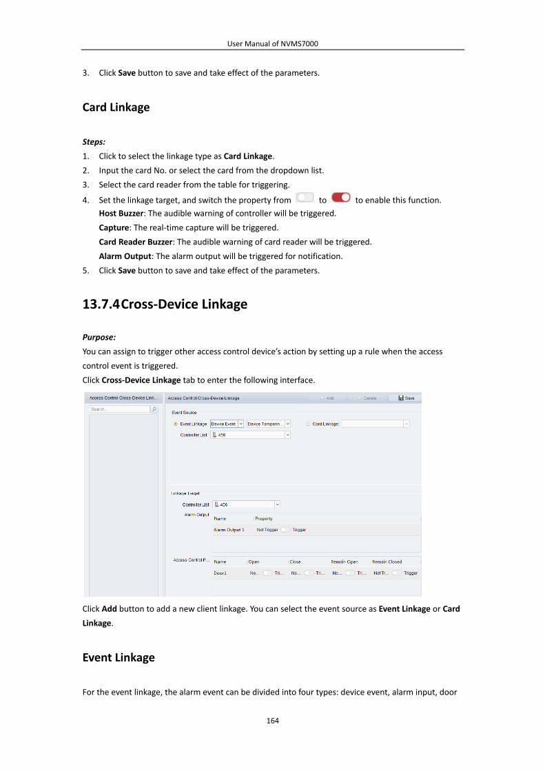
User Manual of NVMS7000
164
3. Click Save button to save and take effect of the parameters.
Card Linkage
Steps:
1. Click to select the linkage type as Card Linkage.
2. Input the card No. or select the card from the dropdown list.
3. Select the card reader from the table for triggering.
4. Set the linkage target, and switch the property from to to enable this function.
Host Buzzer: The audible warning of controller will be triggered.
Capture: The real‐time capture will be triggered.
Card Reader Buzzer: The audible warning of card reader will be triggered.
Alarm Output: The alarm output will be triggered for notification.
5. Click Save button to save and take effect of the parameters.
13.7.4 Cross‐Device Linkage
Purpose:
You can assign to trigger other access control device’s action by setting up a rule when the access
control event is triggered.
Click Cross‐Device Linkage tab to enter the following interface.
Click Add button to add a new client linkage. You can select the event source as Event Linkage or Card
Linkage.
Event Linkage
For the event linkage, the alarm event can be divided into four types: device event, alarm input, door

User Manual of NVMS7000
165
event, and card reader event.
Steps:
1. Click to select the linkage type as Event Linkage, select the access control device as event source,
and select the event type from the dropdown list.
For Device Event, select the detailed event type from the dropdown list.
For Alarm Input, select the type as alarm or alarm recovery and select the alarm input name
from the table.
For Door Event, select the detailed event type and select the door from the table.
For Card Reader Event, select the detailed event type and select the card reader from the
table.
2. Set the linkage target, select the access control device from the dropdown list as the linkage
target, and switch the property from to to enable this function.
Alarm Output: The alarm output will be triggered for notification.
Access Control Point: The door status of open, close, remain open, and remain close will be
triggered. Note: The door status of open, close, remain open, and remain close cannot be
triggered at the same time.
3. Click Save button to save parameters.
Card Linkage
Steps:
1. Click to select the linkage type as Card Linkage.
2. Select the card from the dropdown list and select the access control device as event source.
3. Select the card reader from the table for triggering.
4. Set the linkage target, select the access control device from the dropdown list as the linkage
target, and switch the property from to to enable this function.
Alarm Output: The alarm output will be triggered for notification.
5. Click Save button to save parameters.
13.8 Door Status Management
Purpose:
The door status of the added access control device will be displayed in real time. You can check the
door status and the linked event(s) of the selected door. You can control the status of the door and set
the status duration of the doors as well.
13.8.1 Access Control Group Management
Purpose:
Before controlling the door status and setting the status duration, you are required to organize it into
group for convenient management.
Perform the following steps to create the group for the access control device:

User Manual of NVMS7000
166
Steps:
1. Click on the control panel to open the Device Management page.
2. Click Group tab to enter the Group Management interface.
3. Perform the following steps to add the group.
1) Click to open the Add Group dialog box.
2) Input a group name as you want.
3) Click OK to add the new group to the group list.
You can also check the checkbox Create Group by Device Name to create the new group by
the name of the selected device.
4. Perform the following steps to import the access control points to the group:
1) Click Import on Group Management interface, and then click the Access Control tab to open
the Import Access Control page.
Notes:
You can also select Alarm Input tab and import the alarm inputs to group.
For the Video Access Control Terminal, you can add the cameras as encoding channel to
the group.
2) Select the names of the access control points in the list.
3) Select a group from the group list.
4) Click Import to import the selected access control points to the group.
You can also click Import All to import all the access control points to a selected group.

User Manual of NVMS7000
167
5. After importing the access control points to the group, you can click , or double‐click the
group/access control point name to modify it.
For other detailed operations, please refer to Chapter 3.2Group Management.
13.8.2 Anti‐control the Access Control Point (Door)
Purpose:
You can control the status for a single access control point (a door), including opening door, closing
door, remaining open, and remaining closed.
Click icon on the control panel to enter the Status Monitor interface.
Steps:
1. Select an access control group on the left. For managing the access control group, refer to
Chapter 13.8.1Access Control Group Management.
2. The access control points of the selected access control group will be displayed on the right.

3.
4.
Note
13.
Purp
You c
close
In th
Step
1.
2.
Click icon
Click the follo
You can view
es:
If you select
new anti‐con
The Capture
realized unti
.8.3 Statu
pose:
can schedule
ed.
he Door Status
ps:
Click to select
On the Door S
1) Select a
Remain
on the S
owing button
: Click to open
: Click to close
: Click to keep
: Click to ke
: Click to capt
w the anti‐cont
the status as
ntrol comman
button is ava
l the storage s
us Durati
weekly time p
s module, clic
t a door from
Status Configu
door status b
Open: The d
User M
Status Inform
listed on the
n the door on
e the door on
p the door op
ep the door c
ture the pictur
trol operation
Remain Open
nd being made
ailable when t
server is confi
ion Conf
periods for an
k Status Dura
the access co
uration panel
brush as
door will kee
Manual of NVM
168
ation panel to
Status Inform
ce.
ce.
pen.
losed.
re manually.
n result in the
n/Remain Clo
e.
he device sup
igured. Refer t
figuration
n access contro
ation button t
ontrol device l
on the right,
p open durin
MS7000
o select a doo
mation panel t
Operation Log
sed, the door
pports capture
to Chapter 5.1
n
ol point (door
to enter the S
ist on the left
draw a sched
or
ng the configu
r.
to control the
g panel.
r will keep ope
e function. An
1Remote Stor
r) to remain o
tatus Duratio
.
ule for the sel
.
ured time pe
door.
en/closed unt
nd it cannot be
rage.
pen or remain
n interface.
lected door.
riod. The bru
il a
e
n
ush is

User Manual of NVMS7000
169
marked as .
Remain Closed: The door will keep closed during the configured duration. The brush is
marked as .
2) Click and drag on the timeline to draw a color bar on the schedule to set the duration.
3) When the cursor turns to , you can move the selected time bar you just edited. You can
also edit the displayed time point to set the accurate time period.
When the cursor turns to , you can lengthen or shorten the selected time bar.
3. Optionally, you can select the schedule time bar and click Copy to Whole Week to copy the time
bar settings to the other days in the week.
4. You can select the time bar and click Delete Duration to delete the time period.
Or you can click Clear to clear all configured durations on the schedule.
5. Click Save to save the settings.
6. You can click Copy to button to copy the schedule to other doors.
13.8.4 Real‐time Card Swiping Record
Click Card Swiping Record tab to enter the following interface.

User Manual of NVMS7000
170
The logs of card swiping records of all access control devices will display in real time. You can view the
details of the card swiping event, including card No., person name, organization, event time, etc.
You can also click the event to view the card holder details, including person No., person name,
organization, phone, contact address, etc.
13.8.5 Real‐time Access Control Alarm
Purpose:
The logs of access control events will be displayed in real time, including device exception, door event,
card reader event, and alarm input.
Click Access Control Alarm tab to enter the following interface.
Steps:
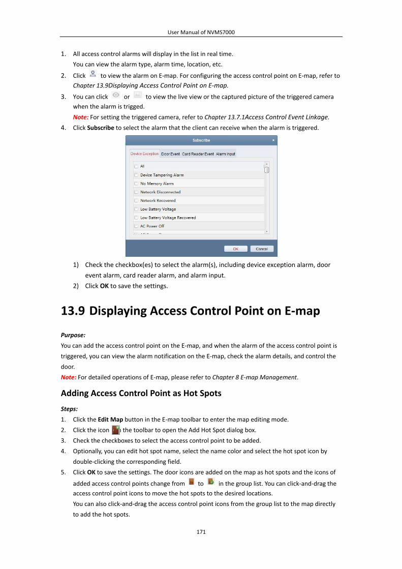
User Manual of NVMS7000
171
1. All access control alarms will display in the list in real time.
You can view the alarm type, alarm time, location, etc.
2. Click to view the alarm on E‐map. For configuring the access control point on E‐map, refer to
Chapter 13.9Displaying Access Control Point on E‐map.
3. You can click or to view the live view or the captured picture of the triggered camera
when the alarm is trigged.
Note: For setting the triggered camera, refer to Chapter 13.7.1Access Control Event Linkage.
4. Click Subscribe to select the alarm that the client can receive when the alarm is triggered.
1) Check the checkbox(es) to select the alarm(s), including device exception alarm, door
event alarm, card reader alarm, and alarm input.
2) Click OK to save the settings.
13.9 Displaying Access Control Point on E‐map
Purpose:
You can add the access control point on the E‐map, and when the alarm of the access control point is
triggered, you can view the alarm notification on the E‐map, check the alarm details, and control the
door.
Note: For detailed operations of E‐map, please refer to Chapter 8 E‐map Management.
Adding Access Control Point as Hot Spots
Steps:
1. Click the Edit Map button in the E‐map toolbar to enter the map editing mode.
2. Click the icon in the toolbar to open the Add Hot Spot dialog box.
3. Check the checkboxes to select the access control point to be added.
4. Optionally, you can edit hot spot name, select the name color and select the hot spot icon by
double‐clicking the corresponding field.
5. Click OK to save the settings. The door icons are added on the map as hot spots and the icons of
added access control points change from to in the group list. You can click‐and‐drag the
access control point icons to move the hot spots to the desired locations.
You can also click‐and‐drag the access control point icons from the group list to the map directly
to add the hot spots.

User Manual of NVMS7000
172
Note: For Video Access Control Terminal, you can also add its camera to the E‐map to view the live
view of the camera.
Modifying Hot Spots
Purpose:
You can modify the information of the added hot spots on the map, including the name, the color, the
icon, etc.
Steps:
1. Click the Edit Map button in the E‐map toolbar to enter the map editing mode.
2. Select the hot spot icon on the map and then click in the toolbar, right‐click the hot spot icon
and select Modify, or double‐click the hot spot icon on the map to open the Modify Hot Spot
dialog box.
3. You can edit the hot spot name in the text field and select the color, the icon and the linked
access control point.
4. Click OK to save the new settings.
To delete the hot spot, select the hot spot icon and click in the toolbar, or right‐click the hot
spot icon and select Delete.
Previewing Hot Spots
Steps:

User Manual of NVMS7000
173
1. Click the Map Preview button in the E‐map toolbar to enter the map preview mode.
2. To control the access control point, you can right click the access control point icon on the map,
and click Open Door, Close Door, Remain Open, and Remain Closed to control the door.
3. If there is any alarm triggered, an icon will appear and twinkle near the hot spot (it will
twinkle for 10s). Click the alarm icon, or you can right click the door icnon and select Display
Alarm Information, to check the alarm information, including alarm type and triggering time.
Note: To display the alarm information on the map, the Alarm on E‐map functionality needs to be
set as the alarm linkage action. For details, refer toChapter 13.7Access Control Event
Configuration.
4. To clear the alarm informationdisplayed on the map, click on the toobar, or right click the
access control point icnon and select Clear Alarm Information to clear the alarms of the selected
zone.
Note: To display the alarm information on the map, the Alarm on E‐map functionality needs to be set
as the alarm linkage action.For details, refer toChapter 6 Event Management.

User Manual of NVMS7000
174
Chapter 14 Time and Attendance
Purpose:
The Time and Attendance module provides multiple functionalities, including shift schedule
management, attendance handling, attendance statistics and other advanced functions.
Before you start:
You should add organization and person in Access Control module. For details, refer to Chapter
13.2Person and Card Management.
Perform the following steps to access the Time and Attendance module.
Click to enter the Time and Attendance module as follows:
14.1 Shift Schedule Management
Open Time and Attendance module and click Shift Schedule Management to enter the Shift Schedule
Management interface.

User Manual of NVMS7000
175
14.1.1 Shift Settings
Purpose:
You can add time period and shift for the shift schedule.
Click Shift Settings to pop up Shift Settings dialog.
Adding Time Period
Steps:
1. Click Time Period tab.
2. Click Add.
3. Set the related parameters.
Name: Set the name for time period.
Start‐Work / End‐Work Time: Set the start‐work time and end‐work time.
Attend at Least: Set the minimum attendance time.
Check‐in / Check‐out Required: Check the checkboxes and set the valid period for check‐in or
check‐out.
Mark as Late/Mark as Early Leave: Set the time period for late or early leave.
Exclude Break Period from Work Duration: Check the checkbox and set the break period
excluded.
Note: Up to 3 break periods can be set.
Set as Pay‐per‐Time Period: Check the checkbox and set the pay rate and minimum time unit.
4. Click Save to save the settings.
The added time period will display on the left panel of the dialog.
You can also click Delete to delete the time period.

User Manual of NVMS7000
176
Adding Shift
Steps:
1. Click Shift Tab.
2. Click Add.
3. Set the name for shift.
4. Select the shift period from the drop‐down list.
5. Configure the shift period with the added time period.
1) Select the time period.
2) Click the time bar to apply the time period for the select day.
You can click the time period on the bar and click or Delete to delete the period.
You can also click Clear to delete all days’ time period.
6. Click Save to save the settings.
The added shift will display on the left panel of the dialog.
You can also click Delete on the left panel to delete the shift.
14.1.2 Shift Schedule Settings
Purpose:
After setting the shift, you can set department schedule, person schedule and temporary schedule.
Note: The temporary schedule has higher priority than department schedule and person schedule.
Department Schedule
You can set the shift schedule for one department, and all the persons in the department will be
assigned with the shift schedule.
Note: In Time and Attendance module, the department list is the same with the organization in

User Manual of NVMS7000
177
Access Control. For setting the organization in Access Control, refer to Chapter 13.2.1Organization
Management.
Steps:
1. Open the Shift Schedule Management interface and select the department on the left panel.
2. Click Department Schedule to pop up Department Schedule dialog.
3. Check Time and Attendance checkbox.
All persons in the department expect those excluded from attendance will apply the attendance
schedule.
4. Select the shift from the drop‐down list.
5. Set the start date and end date.
6. (Optional) Set other parameters for the schedule.
You can select Check‐in Not Required, Check‐out Not Required, Effective for Holiday, Effective for
Overtime, Effective for Multiple Shift Schedules.
Notes:
Multiple Shift Schedules contains more than one time periods. The person can check in/out
in any of the time periods and the attendance will be effective.
Example: If the multiple shift schedules contains three time periods: 00:00 to 07:00, 08:00
to 15:00 and 16:00 to 23:00. The attendance of the person adopting this multiple shift
schedules will be effective in any of the three time periods. If the person checks in at 07:50,
it will apply the nearest time period 08:00 to 15:00 to the person’s attendance.
After checking the Effective for Multiple Shift Schedules checkbox, you can select the
effective time period(s) from the added time periods for the persons in the department.
1) In the Selectable Time Period list on the left, click the added time period and click
to add it to the right.
2) (Optional) To remove the selected time period, select it and click .
7. (Optional) Check Set as Default for All Persons in Department checkbox.

User Manual of NVMS7000
178
All persons in the department will use this shift schedule by default.
8. (Optional) If the selected department contains sub department(s), the Set as Shift Schedule for
All Sub Departments checkbox will display. You can check it to apply the department schedule to
its sub departments.
9. Click Save to save the settings.
Person Schedule
Steps:
1. Open the Shift Schedule Management interface and select the department on the left panel.
2. Select the person(s) on the right panel.
3. Click Person Schedule to pop up Person Schedule dialog.
4. Check Time and Attendance checkbox.
The configured person will apply the attendance schedule.
5. Select the shift from the drop‐down list.
6. Set the start date and end date.
7. (Optional) Set other parameters for the schedule.
You can select Check‐in Not Required, Check‐out Not Required, Effective for Holiday, Effective for
Overtime, Effective for Multiple Shift Schedules.
8. Click Save to save the settings.
Temporary Schedule
Steps:
1. Open the Shift Schedule Management interface and select the department on the left panel.
2. Select the person(s) on the right panel.
3. Click Temporary Schedule to pop up Temporary Schedule dialog.

User Manual of NVMS7000
179
4. Click to set the shift date.
5. Configure the shift date with the added time period.
1) Select the time period.
2) Click the time bar to apply the time period for the select date.
You can click the time period on the bar and click to delete the period.
You can also click Clear to delete all days’ time period.
6. You can click Advanced Settings to advanced attendance rules for the temporary schedule.
7. Click Add to save the settings.
Checking Shift Schedule Details
Steps:
1. On the Shift Schedule Management interface, select the department on the left panel.
2. Select the person(s) on the right panel.
3. Click View to pop up Shift Schedule Details dialog.
You can check the shift schedule details.

User Manual of NVMS7000
180
4. Click Normal Schedule tab.
You can check and edit the normal schedule details.
1) Select the shift from the drop‐down list.
2) Click Attendance Rule Settings to pop up Attendance Rule Settings dialog.
You can check the attendance rules as desired and click OK to save the settings.
3) Click to set the effective date.
4) Click Save to save the settings.
5. (Optional) Click Temporary Schedule tab.

User Manual of NVMS7000
181
You can check and edit the temporary schedule details.
(Optional) Click Add to add temporary schedule for the selected person.
(Optional) Click to edit the time period.
(Optional) Click to delete the temporary schedule.
Exporting Shift Schedule Details
On the Shift Schedule Management interface, select the department on the left panel and click Export
to export all persons’ shift schedule details to local PC.
Note: The exported details are saved in *.csv format.
14.2 Attendance Handling
Purpose:
You can handle the attendance, including check‐in correction, check‐out correction, and leave and
business trip.
Open Time and Attendance module and click Attendance Handling to enter the Attendance Handling
interface.

User Manual of NVMS7000
182
14.2.1 Check‐in/out Correction
Purpose:
You can add, edit, delete, search the check‐in/out correction and generate the related report. You can
also export the check‐in/out correction details to local PC.
Add Check‐in/out Correction
Steps:
1. Click Check‐in/out Correction tab.
2. Click Add to pop up Add Check‐in/out Correction dialog.
3. Set the check‐in/out correction parameters.
For Check‐in Correction: Check Check‐in checkbox and set the actual start‐work time.
For Check‐out Correction: Check Check‐out checkbox and set the actual end‐work time.
4. Click Employee Name field and select the person.

User Manual of NVMS7000
183
You can also input the keyword and click to search the person you want.
5. (Optional) Input the remark information as desired.
6. Click Add to add the check‐in/out correction.
The added check‐in/out correction will display on the Attendance Handling interface.
(Optional) Select the check‐in/out correction and click Modify to edit the correction.
(Optional) Select the check‐in/out correction and click Delete to delete the correction.
(Optional) Click Report to generate the check‐in/out correction report.
(Optional) Click Export to export the check‐in/out correction details to local PC.
Note: The exported details are saved in *.csv format.
Search Check‐in/out Correction
Steps:
1. Click Check‐in/out Correction tab.
2. Set the searching conditions.
Department: Select the department from the drop‐down list.
Name: Input the person name.
Time: Click to set the specified time as time range.
3. Click Search to search the check‐in/out corrections.
The check‐in/out correction details will display on the list.
You can also click Reset to reset the searching conditions.
14.2.2 Leave and Business Trip
Purpose:
You can add, edit, delete, search the leave and business trip and generate the related report. You can
also export the leave and business trip details to local PC.
Add Leave and Business Trip
Steps:
1. Click Leave and Business Trip tab.
2. Click Add to pop up Add Leave and Business Trip Application dialog.

User Manual of NVMS7000
184
3. Select the leave and business trip type from the Type drop‐down list.
You can configure the leave type in Advanced Settings. For details, refer to Chapter 14.3.5Leave
Type Settings.
4. Click to set the specified time as time range.
5. Click Employee Name field and select the person for this application.
You can also input the keyword and click to search the person you want.
6. (Optional) Input the remark information as desired.
7. Click Add to add the leave and business trip.
The added leave and business trip will display on the Attendance Handling interface.
(Optional) Select the leave and business trip and click Modify to edit the leave or business trip.
(Optional) Select the leave and business trip and click Delete to delete the leave or business trip.
(Optional) Click Report to generate the leave or business trip report.
(Optional) Click Export to export the leave or business trip details to local PC.
Note: The exported details are saved in *.csv format.
Search Leave and Business Trip
Steps:
1. Click Leave and Business Trip tab.
2. Set the searching conditions.
Department: Select the department from the drop‐down list.
Name: Input the person name.
Time: Click to set the specified time as time range.
3. Click Search to search the leave and business trips.
The leave and business trip details will display on the list.
You can also click Reset to reset the searching conditions.

User Manual of NVMS7000
185
14.3 Advanced Settings
Purpose:
You can configure the basic settings, attendance rule, attendance check point, holiday settings and
leave type for attendance.
Open Time and Attendance module and click Advanced Settings to enter the Advanced Settings
interface.
14.3.1 Basic Settings
Steps:
1. Click Basic Settings tab to enter the Basic Settings interface.
2. Set the basic settings.

User Manual of NVMS7000
186
Start Day of Each Week: You can select one day as the start day of each week.
Start Date of Each Month: You can select one day as the start date of each month.
3. Set the non‐work day settings.
Set as Non‐Work Day: Check the checkbox(es) to set the selected day(s) as non‐work day.
Set Non‐Work Day’s Color in Report: Click the color filed and select the color to mark the
non‐work day in report.
Set Non‐Work Day’s Mark in Report: Input the mark as non‐work day in report.
4. Click Save to save the settings.
14.3.2 Attendance Rule Settings
Steps:
1. Click Attendance Rule Settings tab to enter the Attendance Rule Settings interface.
2. Set the attendance or absence settings.
If employee does not check in when starting work, you can mark as Absent or Late and set the
late time.
If employee does not check out when end work, you can mark as Absent or Early Leave and set
the early leave duration.
3. Set the Check‐in/out Settings.
You can check the checkbox of Check‐in Required or Check‐out Required and set the valid period.
You can also set the late rule or early leave rule.
Note: The parameters here will be set as default for the newly added time period. It will not affect
the existed one(s).
4. Set the overtime settings.
You can set the overtime rule and set the maximum overtime for each day.
(Optional) You can check Non‐scheduled Work Day checkbox and set the overtime rule for
non‐work day.
5. Click Save to save the settings.

User Manual of NVMS7000
187
14.3.3 Attendance Check Point Settings
You can set the card reader(s) of the access control point as the attendance check point, so that the
card swiping on the card reader(s) will be valid for attendance.
Steps:
1. Click Attendance Check Point Settings tab to enter the Attendance Check Point Settings interface.
2. Click to pop up Add Attendance Check Point dialog.
3. Set the related information.
Check Point Name: Input a name for check point.
Card Reader: Select the card reader from the drop‐down list.
Check Point Function: Select the function for check point.
Door Location: Input the door location.
Check Point Description: Set the description information for check point.
4. Click Add to add the attendance check point.
The added attendance check point will display on the list.
5. (Optional) Check Set All Card Readers as Check Points checkbox.
You can use all the card readers as check points.
Note: If this checkbox is unchecked, only the card readers in the list will be added as attendance
check points.
You can also edit or delete the card readers.

User Manual of NVMS7000
188
Click to edit the card reader.
Click to delete the card reader.
14.3.4 Holiday Settings
Steps:
1. Click Holiday Settings tab to enter the Holiday Settings interface.
2. Click to pop up Add Holiday dialog.
3. Set the related parameters.
Holiday Name: Input the name for the holiday.
Start Date / End Date: Click to specify the holiday date.
4. Click Add to add the holiday.
The added holiday will display on the list.
You can also edit or delete the holiday.
Click to edit the holiday.
Click to delete the holiday.
14.3.5 Leave Type Settings
Purpose
Steps:
1. Click Leave Type Settings tab to enter the Leave Type Settings interface.

User Manual of NVMS7000
189
2. Add the major leave type.
1) Click on the left panel to pop up the Add Major Leave Type dialog.
2) Input the name for major leave type.
3) Click Add to add the major leave type.
You can also edit or delete the major leave type.
Click to modify the major leave type.
Click to delete the major leave type.
3. Add the minor leave type.
1) Select the major leave type.
The minor leave type belonging to this major leave type will display on the right panel.
2) Click on the right panel to pop up the Add Minor Leave Type dialog.
3) Input the name for minor leave type.
4) Click Add to add the minor leave type.
You can also edit or delete the major leave type.

User Manual of NVMS7000
190
Click to modify the minor leave type.
Click to delete the minor leave type.
14.4 Attendance Statistics
Purpose:
You can check the attendance summary, attendance details, abnormal attendance, overtime, card
swiping logs and reports.
Note: You can search the attendance data after 1:00am on the next day.
14.4.1 Attendance Summary
Purpose:
You can get all the attendance information statistics of the employees in the specified time period.
Steps:
1. In the Time and Attendance module, click Attendance Statistics tab to enter the Attendance
Statistics page.
2. Click Attendance Summary item on the left panel to enter the Attendance Summary interface.
3. Set the search conditions, including department, employee name and attendance date.
(Optional) You can click Reset to reset all the configured search conditions.
4. Click Search to start searching and the matched results will list on this page.
(Optional) Click Report to generate the attendance report.
(Optional) Click Export to export the results to the local PC.

User Manual of NVMS7000
191
14.4.2 Attendance Details
Steps:
1. In the Attendance Statistics page, click Attendance Details item on the left panel to enter the
Attendance Details interface.
2. Set the search conditions, including department, employee name, attendance date and status.
(Optional) You can click Reset to reset all the configured search conditions.
3. Click Search to start searching and the matched results will list on this page.
(Optional) You can select a result item in the list and click Correct Check‐in/out to correct the
check‐in or check‐out status.
(Optional) Click Report to generate the attendance report.
(Optional) Click Export to export the results to the local PC.
14.4.3 Abnormal Attendance
You can search and get the statistics of the abnormal attendance data, including No., name and
department of the employees, abnormal type, start/end time and date of attendance. For detailed
operations, refer to Chapter 14.4.1Attendance Summary.
14.4.4 Overtime Search
You can search and get the overtime status statistics of the selected employee in the specified time
period. And you can check the detailed overtime information, including No., name and department of
the employees, attendance date, overtime duration and overtime type. For detailed operations, refer
to Chapter 14.4.1Attendance Summary.

User Manual of NVMS7000
192
14.4.5 Card Swiping Log
You can search the card swiping logs used for the attendance statistics. After searching the logs, you
can check the card swiping details, including name and department of the employees, card swiping
time, card reader authentication mode and card No.. For detailed operations, refer to Chapter
14.4.1Attendance Summary.
14.4.6 Report
In the Attendance Statistics page, click Report item on the left panel to enter the Report interface.
Generating Total Overtime Monthly Report
Steps:
1. Click in the Report Type field to unfold the drop‐down list and select Total Overtime
Monthly Report as the report type.
2. Click Person field to select the person.
3. Click to specify a month.
4. Click Report to start generating the matched total overtime monthly report.
Generating Overtime Details Monthly Report
Select Overtime Details Monthly Report as the report type. You can generate overtime details
monthly report. For detailed operations, refer to Generating Total Overtime Monthly Report.
Generating Attendance Monthly Report
Select Attendance Monthly Report as the report type. You can generate attendance monthly report.
For detailed operations, refer to Generating Total Overtime Monthly Report.
Generating Start/End‐Work Time Report
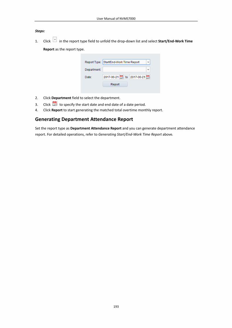
User Manual of NVMS7000
193
Steps:
1. Click in the report type field to unfold the drop‐down list and select Start/End‐Work Time
Report as the report type.
2. Click Department field to select the department.
3. Click to specify the start date and end date of a date period.
4. Click Report to start generating the matched total overtime monthly report.
Generating Department Attendance Report
Set the report type as Department Attendance Report and you can generate department attendance
report. For detailed operations, refer to Generating Start/End‐Work Time Report above.

User Manual of NVMS7000
194
Chapter 15 Video Intercom
Purpose:
The Video Intercom Management module provides the function of video intercom, checking call logs
and managing notice via the NVMS7000 client software.
Note: For the user with access control module permissions, the user can enter the Access Control
module and manage video intercom and search information. For setting the user permission of Access
Control module, refer to Chapter 17.1Account Management.
Before you start:
Before you can remote control the video intercom, you should add the device to the software and
configure the person to link the device in the Access Control module.
Notes:
Up to 16 door stations can be added, and up to 512 indoor stations or master stations can be
added. For details about adding the video intercom, refer to Chapter 3.1Adding the Device.
For details about configuring person in the Access Control module, refer to Chapter 13.2Person
and Card Management.
Click on the Control Panel, or click View‐> Access Control to open the Access Control page.
Click tab on the left icon bar to enter the Video Intercom interface.
15.1 Video Intercom
Purpose:
In this section, you can call the residents via the NVMS7000 client software and the residents can also
call the client software via the indoor station. In addition, calling the client software via door station is
also available.
15.1.1 Calling Indoor Station via NVMS7000
Steps:
1. Click tab on the left icon bar to enter the Video Intercom interface.

User Manual of NVMS7000
195
2. Unfold the organization list on the left panel and click to select a resident group.
The information, including resident name, linked device name and device IP address, of all the
residents in the selected group will display on the right panel.
3. Select a resident, or input the keyword in the Filter field to find the desired resident.
4. Click the icon in the Call Household column to start calling the selected resident.
After answered, you will enter the In Call window.
Click to adjust the volume of the loudspeaker.
Click to hang up.
Click to adjust the volume of the microphone.
Notes:
One indoor station can only connect with one client software.
You can set the maximum ring duration ranging from 15s to 60s, and the maximum speaking
duration ranging from 120s to 600s via the Remote Configuration of indoor station.
15.1.2 Calling NVMS7000 via Indoor Station/Door Station
Steps:
1. Select the client software in the indoor station or door station interface to start calling the
NVMS7000 and an incoming call dialog will pop up in the client software.
Here we take the indoor station as an example.

User Manual of NVMS7000
196
2. Click Answer to answer the call.
Or click Hang Up to decline the call.
3. After you answer the call, you will enter the In Call window.
Click to adjust the volume of the loudspeaker.
Click to hang up.
Click to adjust the volume of the microphone.
For door station, you can click to open the door remotely.
Notes:
One video intercom device can only connect with one client software.
The maximum ring duration can be set from 15s to 60s via the Remote Configuration of the video
intercom device.
The maximum speaking duration between indoor station and NVMS7000 can be set from 120s to
600s via the Remote Configuration of indoor station.
The maximum speaking duration between door station and NVMS7000 can be set from 90s to
120s via the Remote Configuration of door station.

User Manual of NVMS7000
197
15.1.3 Viewing Live Video of Door Station and Outer Door
Station
Purpose:
You can get the live view of the door station and outer door station in the Main View module and
control the door station and outer door station remotely.
In the Main View module, double‐click a door station or outer door station device or drag the device
to a display window to start the live view.
Note: For detailed operations of live view, refer to Chapter 4 Live View.
Right‐click the live view window to open the right‐click menu.
You can click Unlock on the menu to open the door remotely.
15.2 Call Logs
Purpose:
You can check all the call logs, including dialed call logs, received call logs and missed call logs. You can
also directly dial via the log list and clear the logs.
Steps:
1. In the Video Intercom page, click the Call Log tab to enter the Call Log page.
All the call logs will display on this page and you can check the log information, e.g., call status,
start time, resident’s organization and name, device name and ring or speaking duration.

User Manual of NVMS7000
198
2. (Optional) Click the icon in the Operation column to re‐dial the resident.
3. (Optional) Click the icon in the Operation column to delete the call log.
Or you can click Clear button at the upper right corner to clear all the logs.
15.3 Releasing Notice
Purpose:
You can create different types of notices and send them to the residents. Four notice types are
available, including Advertising, Property, Alarm and Notice Information.
Steps:
1. In the Video Intercom page, click Release Notice tab to enter the Release Notice page.
2. Click New Notice button on the left panel to create a new notice.
3. Edit the notice on the right panel.
Steps:
1) Click icon on the Send To field to pop up the Select Resident dialog.

User Manual of NVMS7000
199
2) Check the checkbox(es) to select the resident(s).
Or you can check the All checkbox to select all the added residents.
3) Click OK to save the selection.
4) Input the subject on the Subject field.
Note: Up to 63 characters are allowed in the Subject field.
5) Click in the Type field to unfold the drop‐down list and select the notice type.
6) (Optional) Click Add Picture to add a local picture to the notice.
Note: Up to 6 pictures in the JPGE format can be added to one notice. And the maximum
size of one picture is 512KB.
7) Input the notice content in the Content field.
(Optional) You can also click Clear to clear the edited content.
Note: Up to 1023 characters are allowed in the Content field.
4. Click Send to send the edited notice to the selected resident(s).
The sent notice information will display on the left panel. You can click a notice to view the details on
the right panel.
15.4 Searching Video Intercom Information
Purpose:
You can search the call logs between the NVMS7000 client software and video intercom devices,
device unlocking logs and the sent notice information.
In the Access Control module, click icon tab to open the Search page.
15.4.1 Searching Call Logs
Steps:
1. In the Information Search page, click the Call Log tab to enter the Call Log interface.

User Manual of NVMS7000
200
2. Set the search conditions, including call status, device type, start time and end time.
Call Status: Click to unfold the drop‐down list and select the call status as Dialed,
Received or Missed. Or select All to search logs with all statuses.
Device Type: Click to unfold the drop‐down list and select the device type as Indoor
Station, Door Station, Outer Door Station or Analog Indoor Station. Or select All Devices to
search logs with all device types.
Start Time/End Time: Click to specify the start time and end time of a time period to
search the logs.
(Optional) You can click Reset to reset all the configured search conditions.
3. Click Search and all the matched call logs will display on this page.
For the search results,
(Optional) Check the detailed information of searched call logs, such as call status,
ring/speaking duration, device name, resident organization, etc.
(Optional) Input keywords in the Search field to filter the desired log.
(Optional) Click Export to export the call logs to your PC.
15.4.2 Searching Unlocking Logs
Steps:
1. In the Information Search page, click Unlocking Log tab to enter the Unlocking Log interface.

User Manual of NVMS7000
201
2. Set the search conditions, including unlocking type, device type, start time and end time.
Unlocking Type: Click to unfold the drop‐down list and select the unlocking type as
Unlock by Password, Unlock by Duress, Unlock by Card, Unlock by Resident or Unlock by
Center. Or select All to search logs with all unlocking types.
Device Type: Click to unfold the drop‐down list and select the device type as Door
Station or Door Station (V Series). Or select All Devices to search logs with all device types.
Start Time/End Time: Click to specify the start time and end time of a time period to
search the logs.
(Optional) You can click Reset to reset all the configured search conditions.
3. Click Search and all the matched unlocking logs will display on this page.
For the searching results,
(Optional) Check the detailed information of searched unlocking logs, such as unlocked time,
card No., device No., etc.
(Optional)Input keywords in the Search field to filter the searching result.
(Optional) Click in the Capture column to view the captured pictures.
Note: Viewing captured picture should be supported by device.
(Optional) Click Export to export the unlocking logs to your PC.
15.4.3 Searching Notice
Steps:
1. In the Information Search page, click the Notice tab to enter the Notice interface.

User Manual of NVMS7000
202
2. Set the search conditions, including notice type, subject, recipient, start time and end time.
Notice Type: Click to unfold the drop‐down list and select the notice type as
Advertising Information, Property Information, Alarm Information or Notice Information.
Or select All to search notices with all types.
Subject: Input the keywords in the Subject field to search the matched notice.
Recipient: Input the recipient information in the Recipient field to search the specified
notice.
Start Time/End Time: Click to specify the start time and end time of a time period to
search the notices.
(Optional) You can click Reset to reset all the configured search conditions.
3. Click Search and all the matched notices will display on this page.
For the searching results,
(Optional) Check the detailed information of searched notices, such as sending time, sending
status, etc.
(Optional) Input keywords in the Search field to filter the searching result.
(Optional) Click in the Operation column to pop up Notice Details dialog.
You can view and edit the notice details, check the sending failed/sent succeeded/unread users,
and resend the notice to sending failed/unread users.
(Optional) Click Export to export the notices to your PC.

User Manual of NVMS7000
203
Chapter 16 Log Management
Purpose:
The log files of the client software are stored on the local PC and can be searched for checking. Two
types of log files are provided: client logs and server logs. The client logs refer to the log files of the
client and are stored on the local PC; the server logs refer to the log files of the connected devices and
are stored on the local device.
Click the icon on the control panel to open the Log Search page.
Searching Log Files
Steps:
1. Open the Log Search page.
2. Select the log type. IfRemote Logs is selected, then click to specify the device for search.
3. Click the icon to specify the start time and end time.
Note: You can search the logs within one month.
4. Click Search. The log files between the start time and end time will be displayed on the list.
You can check the operation time, type and other information of the logs.
Note: Please narrow the time range or filter the log type for search if there are too many log files.

User Manual of NVMS7000
204
Filtering Log Files
Purpose:
After searched out successfully, the log files can be filtered by the keyword or condition, and thus you
can find the logs as you want.
Steps:
1. Click Log Filter or the icon on the Log Search page to expand the Log Filter panel.
2. Select Filter by Keyword, and then input keyword for filtering in the text field.
Or select Filter by Condition, and then specify log type in the drop‐down list.
3. Optionally, you can click More… to filter the log files more accurately.
4. Click Filter to start filtering. You can click Clear Filter the cancel the filtering.
Backing up Log Files
Purpose:
The log files, including the client logs and server logs, can be exported for backup.
Steps:
1. Set the condition and search the log file.
2. Click Backup Log to open the Backup Log dialog box.
3. Click the icon , select a local saving path and set a name for the file.
4. Click Backup to export the selected log file for backup.
You can click FileOpen Log File to check the information of the backup log files on local PC.

User Manual of NVMS7000
205
Exporting Picture
Purpose:
The alarm pictures, which are stored in the storage server, can be exported to the local PC.
Steps:
1. Select the alarm pictures.
2. Click Export Picture to open the Export Picture dialog box.
3. Click the icon , select a local saving path and set a name for the file.
4. Click Export to export the selected pictures.

17
Purp
Mult
perm
Click
or cl
Note
Add
Step
1.
2.
3.
4.
5.
6.
7.
Chap
7.1 Acc
pose:
tiple user acco
missions for di
k the ico
ick Tool‐>Acco
e: The user ac
ding the U
ps:
Open the Acc
Click Add Use
Select the use
Administrato
passwords an
Operator: Th
manually. An
Input the use
password stre
ensure your d
Check the che
user in the Co
Optionally, yo
Click Save to
A user na
the passw
For your
choosing
pter 17
Sy
ount M
ounts can be a
ifferent users
on on the con
ount Manage
count you reg
User
count Manage
er to open the
er type from t
or: The admini
nd permission
e operator ac
operator can
er name, passw
ength automa
data security.
eckboxes to a
opy from drop
ou can click De
save the setti
ame cannot co
word cannot b
privacy, we st
g (using a min
User M
7 Acco
ystem
Manage
added to the c
if needed.
ntrol panel,
ement to open
gistered to log
ement page.
e Add User dia
the drop‐dow
istrator accou
s of all operat
count as no p
only modify t
word and con
atically, and w
ssign the perm
p‐down list, to
efault Permis
ngs.
ontain any of
be less than 6
trongly recom
imum of 8 cha
Manual of NVM
206
ount M
Config
ement
client softwar
n the Account
g into the soft
alog box.
n list. Two typ
nt has all perm
tors and its ow
ermission by
the password
firm password
e highly recom
missions for th
o copy the per
sion to restor
the following
6 characters.
mmend changi
aracters, inclu
MS7000
Manage
guratio
re, and you ar
t Managemen
ware is set as
pes of user acc
missions by de
wn account.
default and yo
of its own acc
d as desired. T
mmend you to
he created use
rmissions of th
re the default
characters: /
ing the passwo
uding upper ca
ement
on
e allowed to a
t page.
the super use
counts are sel
efault, and ca
ou can assign
count.
The software
o use a strong
er. Optionally,
he selected us
permissions o
/\ : *?“<> |. An
ord to someth
ase letters, low
t and
assign differen
er.
lectable:
n modify the
the permissio
will judge
g password to
, you can sele
ser.
of this user.
nd the length
hing of your o
wer case lette
nt
ons
ct a
of
wn
ers,

User Manual of NVMS7000
207
numbers, and special characters) in order to increase the security of your product.
Proper configuration of all passwords and other security settings is the responsibility of the
installer and/or end‐user.
Note: Up to 50 user accounts can be added for the client software.
Managing the User
Purpose:
After created successfully, the user account is added to the user list on the Account Management page.
You can edit or delete the information of the user accounts.
To edit the information of the user, select the user from the list, and click Edit User.
To delete the information of the user, select the user from the list, and click Delete User.
For super and administrator user, you can click Copy to to copy the permissions to other user(s).
Note: The super user cannot be deleted and only the password of the super user can be edited.
17.2 System Configuration
Purpose:
The general parameters, live view and playback parameters, image parameters, file saving paths, icon
of live view and playback toolbar settings, keyboard and joystick shortcuts, alarm sounds, email
settings and video intercom parameters can be configured.
Click the icon on the control panel,
or click Tool‐>System Configuration to open the System Configuration page.

User Manual of NVMS7000
208
Note: You can click Default Value to restore the defaults of all the system configurations.
17.2.1 General Settings
Purpose:
The frequently‐used parameters, including the log expired time, network performance, etc., can be
set.
Steps:
1. Open the System Configuration page.
2. Click the General tab to enter the General Settings interface.
3. Configure the general parameters. For details, refer to Table 18.1 General Parameters.
4. Click Save to save the settings.

User Manual of NVMS7000
209
Table 17. 1 General Parameters
Parameters Descriptions
Log Expiry Date The time for keeping the log files, once exceeded, the files will be deleted.
Network Performance The current network conditions. It can be set as Normal, Better or Best.
Maximum Mode
Select Maximize or Full Screen as the maximum mode. For selecting
Maximize, the software will be maximized and the taskbar will display. For
selecting Full Screen, the software will be displayed in full‐screen mode.
Enable Auto‐login Log into the client software automatically.
Pop up Security Prompt
When Using Default
Password
If the default password of the added device has not been changed, the
prompt will pop up for notification.
Enable Alarm Triggered
Pop‐up Image
Enable the image pop‐up when alarms occur. You can also click or
to enable/disable the image pop‐up in Alarm Event interface.
Pop Up Alarm Image for
Minimized Client When
Alarm Triggered Pop‐up
Image Enabled
Enable the alarm image popping up when the client is minimized if the
Alarm Triggered Pop‐up Image function is enabled.
For enabling the Alarm Triggered Pop‐up Image, refer to Chapter 6 Event
Management.
Pop Up Error Message
When Email Settings are
Empty
Set whether the client prompts the error message if the email is not
configured.
For setting the email, refer to Chapter 17.2.8Email Settings.
Auto Time Adjustment Adjust the time automatically at a specified time point.
Enable Keyboard and
Joystick
Set to enable the keyboard or joystick. After enabled, you can set the
shortcuts for the keyboard and joystick. For details, refer to Chapter
17.2.6Keyboard and Joystick Shortcuts Settings.
17.2.2 Live View and Playback Settings
Purpose:
The parameters for live view and playback, including picture format, pre‐play duration, etc., can be
set.
Steps:

User Manual of NVMS7000
210
1. Open the System Configuration page.
2. Click the Live View and Playback tab to enter the Live View and Playback Parameter Settings
interface.
3. Configure the live view and playback parameters. For details, refer to Table 18.2Live View and
Playback Parameters.
4. Click Save to save the settings.
Table 17. 2 Live View and Playback Parameters
Parameters Descriptions
Picture Format Set the file format for the captured pictures during live view or playback.
Merge Downloaded
Video Files
San set the maximum size of merged video file for downloading the video
file by date.
Search Video Files
Stored in
Set to search the video files stored in the local device, in the storage
server, or both in the storage server and local device for playback.
Pre‐play for Set the pre‐play time for event playback. By default, it is 30s.
Enable Screen Toolbar
Display Show the toolbar on each display window in live view or playback.
Prioritize Playback of
Video Files on Storage
Server
Play back the video files recorded on the storage server preferentially.
Otherwise, play back the video files recorded on the local device.
Resume Latest Live View
Status After Restart Resume the latest live view status after you log into the client again.
Disconnect Background
Videos in Single Live
View
In multiple‐window division mode, double‐click a live video to display it in
1‐window division mode, and the other live videos will be stopped for
saving the resource.
Enable Wheel for Zoom
Enable to use the mouse wheel for zoom in or out of the video in PTZ
mode, or for zoom in or restoring of the video in digital zoom mode. In this
way, you can directly zoom in or out (or restore) the live video by scrolling
the mouse.
Skip Unconcerned Video Enable to skip the unconcerned video during VCA playback and the

User Manual of NVMS7000
211
during VCA Playback unconcerned video won’t be played during VCA playback.
17.2.3 Image Settings
Purpose:
The image parameters of the software can be configured, such as view scale, play performance, etc.
Steps:
1. Open the System Configuration page.
2. Click the Image tab to enter the Image Settings interface.
3. Configure the image parameters. For details, refer to Table 18.3 Image Parameters.
4. Click Save to save the settings.
Table 17. 3 Image Parameters
Parameters Descriptions
View Scale The view scale of the video in live view or playback. It can be set as Full
Screen, 4:3, 16:9 or Original Resolution.
Play Performance The play performance of the live video. It can be set as Shortest Delay,
Balanced, or Fluency.
Auto‐change Stream
Type
Change the video stream (main stream or sub‐stream) automatically in live
view according to the size of the display window.
Hardware Decoding
Preferred
Set to enable decoding by hardware for live view and playback. Hardware
Decoding can provide better decoding performance and lower CPU usage
when playing the HD videos during live view or playback.
Enable Highlight Mark the detected objects with green rectangles in live view and playback.
Display Transaction
Information Display the transaction information in the live view.
VCA Rule Display the VCA rule in the live view.
Enable Frame Extracting
for High‐speed Playback
When play back the video in high‐speed (8x speed and above), you can
disable this function to make the image of playback more fluent to view
the details.
Display Temperature on
Captured Picture
For the thermal device, set to display the temperature information on the
captured pictures.

User Manual of NVMS7000
212
17.2.4 File Saving Path Settings
Purpose:
The video files from manual recording, the captured pictures and the system configuration files are
stored on the local PC. The saving paths of these files can be set.
Steps:
1. Open the System Configuration page.
2. Click the File tab to enter the File Saving Path Settings interface.
3. Click the icon and select a local path for the files.
4. Click Save to save the settings.
17.2.5 Toolbar Settings
Purpose:
The icons and the order on the toolbar in the live view and playback window can be customized. You
can set to display what icons and set the icon order.
Steps:
1. Open the System Configuration page.
2. Click the Toolbar tab to enter the Toolbar Settings interface.

User Manual of NVMS7000
213
3. Click to select the icon to display on the toolbar. You can drag the icon to set the icon order when
displaying on the toolbar.
Icons on Live View Toolbar
Stop Live View Stop the live view in the display window.
Capture Capture the picture in the live view process. The capture picture
is stored in the PC.
Record Start manual recording. The video file is stored in the PC.
PTZ Control Start PTZ mode for speed dome. Click and drag in the view to
perform the PTZ control.
Two‐way Audio Start the two‐way audio with the device in live view.
Digital Zoom Enable the digital zoom function. Click again to disable the
function.
Instant Playback Switch to the instant playback mode.
Remote Configuration Open the remote configuration page of the camera in live view.
Icons on Playback Toolbar
Capture Capture the picture in the live view process. The capture picture
is stored in the PC.
Record Start manual recording. The video file is stored in the PC.
Digital Zoom Enable the digital zoom function. Click again to disable the
function.
Download Download the video files of the camera and the video files are
stored in the PC. You can select to download by file or by date.
4. Click Save to save the settings.
17.2.6 Keyboard and Joystick Shortcuts Settings
Purpose:
The keyboard can be connected to the client and be used to control the PTZ cameras. You can set the
shortcuts for keyboard and joystick to get quick and convenient access to the commonly used actions.
Note: This configuration page will display after enabling keyboard and joystick in General Settings. For
details, refer to Chapter 17.2.1General Settings.
Steps:
1. For keyboard: Select the COM port from the drop‐down list if the keyboard is connected to the PC
installed with the client.
2. For keyboard and joystick:
1) Select a certain function from the list.
2) Double‐click the item field under the PC Keyboard, USB Joystick or USB Keyboard column.
3) Select the compound keys operation or number from the drop‐down list to set it as the
shortcuts for the function of the keyboard or USB joystick.
3. Click Save to save the settings.

User Manual of NVMS7000
214
17.2.7 Alarm Sound Settings
Purpose:
When the alarm, such as motion detection alarm, video exception alarm, etc., is triggered, the client
can be set to give an audible warning and the sound of the audible warning can be configured.
Steps:
1. Open the System Configuration page.
2. Click the Alarm Sound tab to enter the Alarm Sound Settings interface.
3. There are six pre‐defined alarm sound type in the list. You can click the icon and select the
audio files from the local path for different alarms.
4. You can also click Add button to add customized alarm sound.
Double click the Type field to customize the alarm sound name as desired.
Click the icon and select the audio files from the local path for different alarms.
5. Optionally, you can click the icon for a testing of the audio file.
6. You can select the added custom alarm sound and click Delete to delete it.
7. Click Save to save the settings.
Note: The format of the audio file can only be *wav.

User Manual of NVMS7000
215
17.2.8 Email Settings
Purpose:
An email notification can be sent when a system alarm occurs. To send the email to some specified
receivers, the settings of the email need to be configured before proceeding.
Steps:
1. Open the System Configuration page.
2. Click the Email tab to enter the Email Settings interface.
3. Input the required information.
Server Authentication (Optional): If your email server requires authentication, check this
checkbox to use authentication to log into the server and enter the login user name and password
of your email account.
SMTP Server: Input the SMTP Server address.
Port: Input the communication port of email service. The port is 25 by default.
User Name: Input the user name of the sender email address if Server Authentication is checked.
Password: Input the password of the sender Email address if Server Authentication is checked.
Sender Address: Input the email address of the sender.
Receiver 1 to 3: Input the email address of the receiver. Up to 3 receivers can be set.
4. Optionally, you can check the checkbox Enable SSL to increase the security of email sending.
5. Optionally, you can click Send Test Email to send an email to the receiver for test.
6. Click Save to save the settings.

User Manual of NVMS7000
216
17.2.9 Video Intercom Settings
Purpose:
You can configure the video intercom parameters accordingly.
Steps:
1. Open the System Configuration page.
2. Click the Video Intercom tab to enter the Video Intercom Settings interface.
3. Input the required information.
Ringtone: Click the icon and select the audio file from the local path for the ringtone of
indoor station. Optionally, you can click the icon for a testing of the audio file.
Max. Ring Duration: Input the maximum duration of the ringtone.
Max. Speaking Duration with Indoor Station: Input the maximum duration of speaking with the
indoor station.
Max. Speaking Duration with Door Station: Input the maximum duration of speaking with the
door station.
4. Click Save to save the settings.

User Manual of NVMS7000
217
Chapter 18 Statistics
Purpose:
In Statistics, it provides eight modules for data statistics via the software: Heat Map, People Counting,
Counting, Road Traffic, Face Retrieval, License Plate Retrieval, Behavior Analysis, and Face Capture.
The Heat Map module provides the display of the heat map statistics.
The People Counting module provides the display of the people counting statistics.
The Counting module provides the display of the counting statistics.
The Road Traffic module provides the display of the road traffic data.
Face Retrieval module provides the query of the picture of face.
License Plate Retrieval module provides the query of the license plate number.
Behavior Analysis module provides the query of behavior analysis.
Face Capture module provides the data search and statistics for captured faces pictures.
18.1 Heat Map
Purpose:
Heat map is a graphical representation of data represented by colors or the heat map data can be
displayed in line chart. The heat map function of the camera usually be used to analyze the visit times
and dwell time of customers in a configured area.
Before you start:
Please add a heat map network camera to the software and properly configure the corresponding
area. The added camera should have been configured with heat map rule.
Note: The heat map network camera should be added to the software as Encoding Device, please
refer to Chapter3.1Adding the Device for detailed configuration. For configuring heat map rule, please
refer to the User Manual of the heat map network camera.
Click the icon on the control panel to open the Heat Map page.

User Manual of NVMS7000
218
Steps:
1. Open the Heat Map page.
2. Click to select a heat map camera in the area panel.
3. Select the report type as needed and set the start time.
4. Click Generate Heat Map and the heat map of the camera displays. You can click or to
display the statistics in line chart or picture mode.
In picture mode, the red color block (255, 0, 0) indicates the most welcome area, and blue color
block (0, 0, 255) indicates the less‐popular area.
5. (Optional) Click to save the detailed data of heat map to your PC.
18.2 People Counting Statistics
Purpose:
You can check the people counting statistics of the added people counting device and the statistics
can be displayed in line chart or histogram. The detailed data can be exported for local storage.
Before you start:
Please add a people counting device to the software and properly configure the corresponding area.
The added device should have been configured with people counting rule.
Note: The people counting device should be added to the software as Encoding Device, please refer to
Chapter3.1Adding the Device for detailed configuration. For configuring people counting rule, please
refer to the User Manual of the people counting device.
Click the icon on the control panel to open the People Counting page.

User Manual of NVMS7000
219
Steps:
1. Open the People Counting page.
2. Select the report type as needed and set the time.
1) Select daily report, weekly report, monthly report or annual report as the time type for the
report.
2) Select One Camera in Multi‐period or One Camera in One Period as the statistics type.
One Camera in Multi‐period: One camera can be selected for generating the statistics
for it of the two time periods.
One Camera in One Period: One camera can be selected for generating the statistics
for it of one time period.
3) Select Enter, Exit, or Enter and Exit as the data type.
Enter: The people entered will be counted.
Exit: The people exited will be counted.
Enter and Exit: Both people entered and exited will be counted.
4) Set the time period(s).
3. Select the camera for generating the report.
4. Click Search and the statistics displays on the right panel. The detailed data for each hour, day or
month will be also displayed.
By default, the statistics are shown in histogram form. You can switch it to line chart by clicking
the .
5. (Optional) Click to save the detailed data of people counting to your PC.

User Manual of NVMS7000
220
18.3 Face Capture
Purpose:
You can check the captured faces statistics of the added face capture device and the statistics can be
displayed in table, line chart, pie chart or histogram. The detailed data can be exported for local
storage.
Before you start:
Please add the face capture device to the software and properly configure the corresponding settings.
For detailed settings, please refer to the User Manual of the device.
Note: The face capture device should be added to the software as Encoding Device, please refer to
Chapter3.1Adding the Device for detailed configuration.
Click the icon on the control panel to open the Face Capture page.
Steps:

User Manual of NVMS7000
221
1. Open the Face Capture page.
2. Select the report type as needed and set the time.
1) Select daily report, weekly report, monthly report or annual report as the time type for the
report.
2) Select Multi‐camera in One Period as the statistics type.
Multi‐camera in One Period: Multiple cameras can be selected for generating the statistics
for them of one time period.
3) Select Age, Gender or Number of People as the data type.
4) Set the time period.
3. Select the cameras for generating the report.
4. Click Search and the statistics displays on the right panel. The detailed data for each hour, day or
month will be also displayed.
For Age and Gender statistics, the statistics are shown in pie chart.
For Number of People statistics, the statistics are shown in histogram form by default. You can
switch it to line chart by clicking the .
5. (Optional) Click to save the detailed data of captured face pictures to your PC.

User Manual of NVMS7000
222
Troubleshooting
Live View
Problem:
Failed to get the live view of a certain device.
Possible Reasons:
Unstable network or the network performance is not good enough.
The device is offline.
Too many accesses to the remote device cause the load of the device too high.
The current user has no permission for live view.
The version of the client software is below the needed version.
Solutions:
Check network status and disable other not in use process on your PC.
Check the device network status.
Restart the device or disable other remote access to the device.
Log in with the admin user and try again.
Download the client software of the latest version.
Recording
Problem:
Local recording and remote recording are confused.
Solutions:
The local recording in this manual refers to the recording which stores the video files on the
HDDs, SD/SDHC cards of the local device.
The remote recording refers to the recording action commanded by the client on the remote
device side.
Playback
Problem:
Failed to download the video files or the downloading speed is too slow.
Possible Reasons:
Unstable network or the network performance is not good enough.
The NIC type is not compatible.
Too many accesses to the remote device
The current user has no permission for playback.
The version of the client software is below the needed version.
Solutions:
Check network status and disable other not in use process on your PC.
Directly connect the PC running the client to device to check the compatibility of the NIC card.
Restart the device or disable other remote access to the device.
Log in with the admin user and try again.
Download the client software of the latest version.