nutsvolts2009-01
TRANSCRIPT

Vo
l.30 No.1
NU
TS
& V
OLT
SP
RO
TO B
UD
DY
•S
PIC
E S
IMU
LAT
ION
•M
OS
FET
S •
Ho
w T
o- S
MT
SO
LDE
RIN
G
Janu
ary 2009
0 374470 89295
01>U.S. $5.50 CANADA $7.00
Cover.qxd 12/11/2008 1:25 PM Page 1


Wi-Fi and Ethernet Versions
Full Page.qxd 12/10/2008 5:27 PM Page 3


Jameco Electronics’ new catalog and enhanced
Jameco.com website are two tools that are designed
to work together to give electronic professionals
faster access to the hottest components in
the industry.
Color coded references throughout the catalog
assist you in analyzing a wide range of brand
choices (from franchise sourced to house brands to
factory overruns) offering you more pricing options
than you'll see anywhere else. Web codes allow you
to quickly jump from catalog to website to view
additional specifications, application notes, photos
and more products. You'll find exactly what you're
looking for without having to wade through hundreds
of thousands of products on a complicated website
or wielding a twenty pound catalog.
With a flip of the page or a click of the mouse,
you have all the tools you need at your fingertips.
Reach for Jameco first and order your
catalog today.
Experience a Faster Way to Search for Components!
Call 1-800-831-4242 or Visit www.Jameco.com/Speed for the ride of your life!
Order your
web-enabled
catalog today!
Full Page.qxd 12/10/2008 5:29 PM Page 5

Nuts & Volts (ISSN 1528-9885/CDN Pub Agree #40702530) is published monthly for $24.95per year by T & L Publications, Inc., 430 Princeland Court, Corona, CA 92879. PERIODICALSPOSTAGE PAID AT CORONA, CA AND AT ADDITIONAL MAILING OFFICES. POST-MASTER: Send address changes to Nuts & Volts, P.O. Box 15277, North Hollywood,CA 91615 or Station A, P.O. Box 54,Windsor ON N9A 6J5; [email protected].
6 January 2009
Features
Projects
5500 PPoowweerr MMOOSSFFEETTss ■ By Gerard Fonte
Part 1 will cover the theory behind these useful devices that have a lot of overlooked features.
5544 AA TToouucchh ooff SSppiiccee ■ By Peter Stonard
This month, make discoveries about IC circuits that are well-known and learn more about the concepts of sub-circuits and macromodels.
6600 HHooww TToo:: SSuurrffaaccee MMoouunntt SSoollddeerriinngg ■ By Robert DoerrGet over your fear of working with these tiny components.
34 Instrumentation for Model Rocketry Incorporate additional instrumentation to a flight recorder to measure a rocket’s rate of roll, relative altitude, and booster-stage separation detection. ■ By Michael Bessant
40 16x16 Tri-Colored LED Matrix — Real Time Clock for the Parallax SX52 This project allows the user to create their own scrolling display to show the time (or other messages) in multiple colors. ■ By Timothy Gilmore
44 The Proto Buddy Take proto circuit building to the next level with this device that allows you to expand your existing boardso you can create all kinds of circuits. ■ By Jim Stewart
Columns
Departments08 DEVELOPING
PERSPECTIVES31 NEW PRODUCTS32 SHOWCASE66 ELECTRO-NET
86 NV WEBSTORE90 CLASSIFIEDS92 TECH FORUM96 AD INDEX
●●●● Advanced Level
●●●● Advanced Level
●●●● Intermediate Level
Page 40
Page 44
JJaannuuaarryy 22000099 wwwwww..nnuuttssvvoollttss..ccoomm
CC oo nn tt ee nn tt ss
12 TechKnowledgey 2009EEvveennttss,, AAddvvaanncceess,, aanndd NNeewwssTopics covered include reconnecting brain cells, a new unified storage appliance, don’t mix headphones and pacemakers, plus more.
15 Personal RoboticsUUnnddeerrssttaannddiinngg,, DDeessiiggnniinngg && CCoonnssttrruuccttiinnggRRoobboottssRobo resolutions for 2009.
18 Stamp ApplicationsPPuuttttiinngg tthhee SSppoottlliigghhtt oonn BBAASSIICC SSttaammpp PPrroojjeeccttss,, HHiinnttss && TTiippssControl from the couch — redux.
26 Q & ARReeaaddeerr QQuueessttiioonnss AAnnsswweerreedd HHeerreeHigh impedance preamp, audio to LED display driver, FM shutdown problem, more.
68 Getting Started With PICsTThhee LLaatteesstt iinn PPrrooggrraammmmiinngg MMiiccrrooccoonnttrroolllleerrssI2C communication.
72 The Design CycleAAddvvaanncceedd TTeecchhnniiqquueess ffoorr DDeessiiggnn EEnnggiinneeeerrss
Chatting up a thumbdrive.
80 Smiley’s WorkshopAAnn AAVVRR CC PPrrooggrraammmmiinngg SSeerriieess
A menu navigator.
Jan 09.qxd 12/10/2008 6:02 PM Page 6

Information and Sales | [email protected] | www.netburner.com
Telephone | 1-800-695-6828
NetBurner Serial to Ethernet Development Kits are available
to customize any aspect of operation including web pages,
data filtering, or custom network applications. All kits include
platform hardware, ANSI C/C++ compiler, TCP/IP stack, web server,
e-mail protocols, RTOS, flash file system, Eclipse IDE, debugger,
cables and power supply.
SERIAL TO ETHERNET SOLUTIONSSimple Ethernet connectivity
for serial devices
Works out of the box - no programming is required
Customize to suit any application with low-cost
development kit
Features:
10/100 Ethernet
TCP/UDP mode
DHCP/Static IP Support
Data rates up to 921.6kbps
Web-based configuration
PK70EX2324-port serial-to-Ethernet serverwith RS-232 support
$269Qty. 100
SB72EX2-port serial-to-Ethernet server
with RS-232 & RS-485/422 support
$139Qty. 100
SB702-port serial-to-Ethernet serverwith TTL support
Device P/N: SB70-100CRKit P/N: NNDK-SB70-KIT
Device P/N: SB72-EX-100CRKit P/N: NNDK-SB72EX-KIT
Device P/N: PK70EX-232CRKit P/N: NNDK-PK70EX232-KIT
$69Qty. 100
Need a custom solution?
Full Page.qxd 10/7/2008 11:21 AM Page 7

BBuuiillddiinngg aa HHoommee RReeccoorrddiinngg SSttuuddiioo
Want to test the extent of your knowledge of appliedelectronics? Then try designing a home recording
studio. Thanks to the affordable music recording and playback devices you can have fun creating your ownmusic. Moreover — from an electronics enthusiast’s perspective — a home recording studio is a place whereyou can apply your creativity. However, designing andthen getting the most out of a home recording studiorequires a considerable understanding of electronics, frompower supplies and digital signal processing to acoustics.
OOppttiioonnssVarious options available for creating a home
recording studio range from a pocket digital recorder and built-in microphone in your bedroom to a dedicated,acoustically treated room with the latest computer hardware and software tools, professional microphones,mixers, and signal processors. Budget is obviously a
consideration, as is available space.A popular, low-cost option ($350 and up) is a studio
in a box. This is an all-in-one, stand-alone recording appliance, such as the 64-track Boss BR-600 DigitalRecorder, with built-in microphone, drum machine, andsignal processing effects. A laptop or desktop computerwith an analog-to-digital interface for capturing sound andassociated software, as well as microphones and preamps,is a modest cost solution. A computer offers more flexibility and room for growth than a studio in a box.
PPoowweerrI’ve learned — the hard way — that the first thing to
be aware of is the seemingly odd standards of the musicindustry. For example, the power supply polarity used byeffects pedals and other audio peripherals is often‘reversed.’ That is, it’s common practice with audio gearoutfitted with coaxial power connectors to have the outside of the jacket positive and the inside negative —exactly the opposite of most consumer electronics. I’ve
DEVELOPINGPERSPECTIVESby Bryan Bergeron, Editorby Bryan Bergeron, Editor
8 January 2009
DevPerspectives.qxd 12/11/2008 2:13 PM Page 8

mistakenly plugged in a standard power brick to a preamp,which resulted in a fried one. You can avoid this mistakeby clearly marking your music power supply bricks to distinguish them from your standard polarity bricks.
CCoommppuutteerr TToooollssAnother industry standard that you’ll discover is
Digidesign’s Pro Tools. This software and hardware combi-nation enables you to record and then manipulate soundon your PC. There are numerous software options for bothPCs and Macs. For example, I use Logic Studio on a Mac.However, Pro Tools is the entrenched standard. Regardlessof your computer hardware and software, you’ll need lotsof disk storage and, more importantly, high throughput.Think fast terabyte drives. Expect to use 0.5 GB or morefor an eight-track recoding of a 10 minute song.
CCaabblleessCables and connectors for recording are specialized.
When selecting cable, think thick copper to minimizeresistance losses. Conversely, when you select high-imped-ance microphone and instrument cables, think shieldingfor noise reduction and minimum capacitance per foot tominimize high frequency loss. Bulky XLR and old-fash-ioned 1/4 inch still handle most of the audio signals in a home or professional recording studio. Whileon the topic of impedance matching, consider that microphones, guitars, and other instruments typically present a high-impedance output (15K–1M ohm) which ismuch higher than the typical low-impedance line input toan analog-to-digital converter. You'll need a preamp or adirect box to compensate for the impedance mismatchand assure the signal level is appropriate for your inputdevice. A direct box can be as simple as a transformerwith input and output connectors.
SSiiggnnaall PPrroocceessssoorrssStand-alone, floor, and rack-
mounted signal processing options —filters, amplifiers, and various effects— can help you achieve the tone youdemand. At a minimum, you shouldconsider an eight channel virtual orhardware mixing board. A mixerallows you to adjust levels of variousinputs and combine them into a single mono or stereo track. I preferthe feel of a real hardware mixer overa virtual mixer defined in software.
GGrroouunnddOne of the headaches of
connecting a half-dozen amplifiers,effect boxes, and computers togetheris that you have to pay attention toground loops. Often, the only practical way to remove 60 Hz humfrom the audio signal is to lift theground on one or more devices in
the signal chain. This can be accomplished by using a 3-to-2 pronged adapter. Some gear has a built-in groundlift switch. There are obvious safety issues associated withlifting the ground in an AC powered device. In short, don’tallow your body to complete a ground fault circuit.
January 2009 9
Continued on page 10
DevPerspectives.qxd 12/10/2008 3:48 PM Page 9

IInnffoorrmmaattiioonnYou can be the best circuit designer in the world and find yourself lost
in the vocabulary and sheer volume of choices in the home recording world.Prepare to spend some time in your local music store or, better yet, with someone who has a system up and running. And avoid the common misstep of designing your home recording studio one component at a time. You couldrun out of money before you're through and end up with a mismatched, expensive system. Better to configure the entire system and then look for thebest price.
Of course, you can save money — and have fun — by making your owncables, effects boxes, and signal monitoring devices. NV
Published Monthly ByTT && LL PPuubblliiccaattiioonnss,, IInncc..
430 Princeland Ct.Corona, CA 92879-1300
((995511)) 337711--88449977FAX ((995511)) 337711--33005522
Webstore orders only 11--880000--778833--44662244wwwwww..nnuuttssvvoollttss..ccoomm
SubscriptionsToll Free 11--887777--552255--22553399
Outside US 11--881188--448877--44554455P.O. Box 15277
North Hollywood, CA 91615
FOUNDER/ASSOCIATE PUBLISHERJack Lemieux
PUBLISHERLarry Lemieux
ppuubblliisshheerr@@nnuuttssvvoollttss..ccoomm
ASSOCIATE PUBLISHER/VP OF SALES/MARKETING
Robin Lemieuxddiissppllaayy@@nnuuttssvvoollttss..ccoomm
EDITORBryan Bergeron
tteecchheeddiitt--nnuuttssvvoollttss@@yyaahhoooo..ccoomm
TECHNICAL EDITORDan Danknick
ddaann@@tteeaammddeellttaa..ccoomm
CONTRIBUTING EDITORSJeff Eckert Russ KincaidVern Graner Fred EadyJoe Pardue Peter StonardGerard Fonte Mike BessantTimothy Gilmore Robert DoerrChuck Hellebuyck Jon WilliamsJim Stewart
CIRCULATION DIRECTORTracy Kerley
ssuubbssccrriibbee@@nnuuttssvvoollttss..ccoommSHOW COORDINATOR
Audrey LemieuxMARKETING COORDINATOR
WEBSTOREBrian Kirkpatrick
ssaalleess@@nnuuttssvvoollttss..ccoommWEB CONTENT
Michael Kaudzewweebbssiittee@@nnuuttssvvoollttss..ccoomm
PRODUCTION/GRAPHICSShannon Lemieux
AJ CohenADMINISTRATIVE ASSISTANT
Debbie Stauffacher
Copyright © 2009 by T & L Publications, Inc.All Rights Reserved
All advertising is subject to publisher’s approval. We arenot responsible for mistakes, misprints, or typographicalerrors. Nuts & Volts Magazine assumes no responsibilityfor the availability or condition of advertised items or forthe honesty of the advertiser. The publisher makes noclaims for the legality of any item advertised in Nuts &Volts. This is the sole responsibility of the advertiser.Advertisers and their agencies agree to indemnify and protect the publisher from any and all claims, action, or expense arising from advertising placed in Nuts & Volts.Please send all editorial correspondence, UPS, overnightmail, and artwork to: 443300 PPrriinncceellaanndd CCoouurrtt,, CCoorroonnaa,, CCAA 9922887799.10 January 2009
Continued from page 10
DevPerspectives.qxd 12/10/2008 8:21 PM Page 10


RECONNECTINGBRAIN CELLS
Let's say you have a toilet thatworks fine until the chain that
connects the flush handle to the flapper breaks. One way to fix itwould be to hook up a motion sensor and a transmitter to the handle such that whenever the system detects movement, it transmits a signal. This signal ispicked up by a receiver that triggersa power supply and a solenoid in the tank which lifts the flapper andinvokes a flush. Or, you could justreplace the chain. Duh!
Now let's say you have a humanbeing whose leg no longer functionsbecause of spinal cord damage. Oneway to address that is to pick upsome brain waves, decode and convert the neural signals so they can be processed by a computer,and have the computer send signalsto a robotic prosthesis device thatcreates the desired movement.
Or, you could just reconnect thebrain and the leg. Duh!
Enter Drs. Eberhard Fetz andChet Moritz, both of the Universityof Washington (www.washington.edu), who reasoned that, given thatspinal injuries leave nerve cells in the
brain and the muscles unimpaired, itmight be possible to reconnect themuscles to the motor cortex and letthem start communicating again.Their study, recently reported in thejournal Nature, indicates that it could very well work. In researchconducted at the WashingtonNational Primate Center, theynumbed some monkey’s wrist nerveswith a local anesthetic. The doctorsthen provided direct, artificial stimulation from arbitrarily chosenmotor cortex cells to multiple muscles. Oddly enough, the monkeyslearned to flex and extend their wriststo play video games.
Despite the nerve block, themonkeys were able to control thecontraction strength of their wristmuscles to match a set of targets ona computer screen, and they got better at it as they learned to controlthe neurons. The odd thing is thateven neurons usually unrelated towrist movement could be used tocontrol the muscles, which hints thatstroke victims someday may learn touse undamaged brain areas to restorelost function.
The study was conducted usinglab instruments, but Fetz and Moritzalso built a portable device from off-the-shelf components to convertsignals from the motor cortex neuroncells into stimuli. The matchbox-sizedevice runs off AA batteries, and further miniaturization should be relatively simple. Considerable refinement is needed, but with support from the National Institutesof Health (NIH) Neurology Institute,the concept looks promising.
ANOTHER LEAP TOWARD THE SUN?
One of the obstacles to practicalsolar energy is, of course, the
relative inefficiency of the panels. Partof the problem is that existing panelsabsorb only about two thirds of the sunlight that strikes it, meaning thatabout a third of the power potentialslips away unharnessed. However, someresearchers at Rensselaer Polytech(www.rpi.edu) have demonstrated anew antireflective coating that allows apanel to (a) make use of the entire solarspectrum and (b) gather light evenlyand equally from all angles, thus eliminating the need to constantly reposition the panels to track the sun'sposition in the sky. The result is anabsorption rate of 96.21 percent.
According to Prof. Shawn-Yu Lin,project leader, typical antireflective coatings are engineered to transmit lightof one particular wavelength. The newcoating stacks seven of these layerssuch that each layer enhances theantireflective properties of the layerbelow it. These additional layers alsohelp to "bend" the flow of sunlight to an angle that augments the coating'santireflective properties, so each layerhelps to capture any light that may have otherwise been reflected off of the layers below it.
The layers are made up of silicondioxide and titanium dioxide nanorodspositioned at an oblique angle so "eachlayer looks and functions similar to adense forest where sunlight is capturedbetween the trees."
There was no speculation abouthow soon the panels might be
TECHKNOWLEDGEYEVENTS, ADVANCES, AND NEWS 20
09
■ BY JEFF ECKERT
ADVANCED TECHNOLOGY
■ Drs. Moritz (L) and Fetz in theirUW lab.
■This nanoengineered coating allows solar panels to absorb theentire sunlight spectrum.
12 January 2009
PHOTO BY RENSSELAER/SHAWN LIN.
Tech209.qxd 12/8/2008 1:41 PM Page 12

commercially available, and we have tokeep in mind that other promising dyeand coating formulations ultimatelycould not adequately withstand continuous exposure to sunlight. But this could be a significant step forward.
COMPUTERS ANDNETWORKINGNEW UNIFIED STORAGEAPPLIANCE
Billed as the "world's first unifiedstorage appliances," Sun
Microsystems recently introduced the Sun Storage 7000 family of "openstorage" devices, designed to "radicallysimplify storage management andproblem solving at breakthroughspeed and scale." According to Sun,"These new systems radically simplifythe way information is managed and can deliver up to 75% cost/performance savings to customers.This is the biggest thing to happen tostorage in decades."
Three models are available: the7110 (ultracompact model with 2 TBof storage); the 7210 (mid-range storage featuring up to 48 TB ofcapacity); and the 7410 (support forup to 0.5 PB of capacity that includessupport for read and write optimizedSSDs and Sun's Flash Hybrid StoragePool technology).
All of the 7000 systems includecomprehensive data services at noextra cost, such as snap/clone,restore, mirroring, RAID-5, RAID-6,replication, active-active clustering,compression, thin provisioning, CIFS,NFS, iSCSI, HTTP/FTP, and WebDAV.For details, visit www.sun.com. Butcheck your bank account first. Thedevices start at $10,000 and top offat $89,490 for the 7410 in a clustered12 TB configuration.
RUGGED MILITARY COMPUTER INTRODUCED
There may not be much going onin the consumer PC market right
now, but the new MQS4U-20A from Chassis Plans (www.chassis-plans.com) is a pretty interesting
beast. It's a rugged military-graderackmount computer system basedon an ultra high-performance TyanThunder n6550EX S4989 Quad AMDOpteron® processor motherboardand an EVGA e-GeForce 9800 GX2graphics processing unit, which offerstwo DVI-I outputs with up to 2560 x1600@60 Hz graphics.
Intended for applications where ashort depth, light weight, and sturdyrackmount system are required, thesystem is optimized for installation intransit cases or mobile installationssuch as aircraft and other vehicles. Itmeets all appropriate Mil standards forshock, vibration, and environmentalspecifications, so you can beat itaround all you want.
The machine can be configuredwith up to 128 GB of 667 MHzDDR2 RAM and two 1 TB enterprise-level drives. The single or dual redundant 1,200W power suppliesare kept cool by four 120 CFM fans.All this is wrapped in a 5052 high-strength aluminum case. As you mightexpect, no list price was offered. Butif you're interested, you can get aquote via the company's website.
CIRCUITSAND DEVICESANY RATE, ANY OUTPUTCLOCK GENERATOR
Silicon Laboratories, Inc. (www.silabs.com), the Austin-based
producer of high-performance, analog-intensive, mixed-signal ICs, has introduced a family of clock generators and buffers that provide a high level of frequency flexibility.Based on the company's MultiSynthtechnology, the Si5338 is capable ofsynthesizing any frequency from 0.16to 350 MHz and select frequencies to
700 MHz on each of the device'sfour differential outputs, thus simplifying timing architectures byreplacing four discrete phase-lockedloop (PLL) devices with a single IC.
Silabs claims best-in-class performance and integration whileshortening design cycles for applications such as next-generationcommunications equipment, wirelessbase stations, broadcast video, test and measurement, and dataacquisition. At 1 ps RMS random jittertypical, the Si5338 can simultaneouslygenerate low jitter clocks for a varietyof ICs, including processors, FPGAs,ASICs, memory, and physical layertransceivers. The device generatesfour differential or eight single-endedoutputs per device, eliminating theneed for external clock distributionbuffers. In addition to frequency, each output clock is independentlyconfigurable in terms of supply voltage (1.5, 1.8, 2.5, 3.3 volts) andsignal format (LVPECL, LVDS, CMOS,HCSL, SSTL, HSTL), eliminating theneed for external level translators, and reducing BOM cost and complexity.
If you don't need the programmability provided by theSi5338, there is the option of a broad line of Si5334 pin controlledclock generators for Ethernet, Fibre Channel, PCI Express, T1/E1, broadcast video (HDTV),
T E C H K N O W L E D G E Y 2 0 0 9
■ Sun's Storage 7410,top dog in the7000 family.
PHOTO COURTESY OF SUN MICROSYSTEMS.
January 2009 13
■ Chassis Plans' MQS4U-20A, intendedfor rugged military applications.
Tech209.qxd 12/8/2008 1:41 PM Page 13

and SONET/SDH OC-3/12/48 applications. Packaged in a 24 lead 4 x 4 mm QFN package, the Si5338and Si5334 devices are available atprices starting at $9.31 in 10,000piece quantities, depending on output frequency.
MEMS MIKES FOR CONSUMER APPS
Early in 2007, Scotland's WolfsonMicroelectronics (www.wolfson
micro.com) acquired a local MEMSdesign company, Oligon Ltd., whichwas integrated into Wolfson's plansto add more hardware and softwaretechnologies to its audio processing,A/D, and D/A technology. In October,this emerged as a new family of silicon microphones, beginning withthe WM7110 and WM7120.
These are compact, high signal-to-noise ratio (SNR) analog mikes foruse in consumer applications thatrequire low power consumption andhigh signal quality. Using Wolfson'sCMOS/MEMS membrane technology,the new devices promise high reliability and performance in aminiature, low profile package.Wolfson is also offering enhancedWM7110E and WM7120E versions,which are said to be the first MEMSsilicon microphones to deliver a
sensitivity tolerance of ±/-1 dB. TheWM7110 (4.72 x 3.76 x 1.25 mm)and ultra-compact WM7120 (3.76 x2.95 x 1.10 mm) devices typicallyconsume only 160A. making themideal for portable applications suchas mobile phones, portable mediaplayers, digital still cameras, videocameras, navigation devices, andnoise-cancelling headphones.
Both offer 62 dB SNR (A-weighted) performance and totalharmonic distortion of 0.5% max at100 dB SPL. Sample quantities shouldbe available by the time you readthis. Prices start at $1.64 in quantitiesof 1,000.
INDUSTRY ANDTHE PROFESSIONINTEL RECOGNIZED BY EPA
At an award ceremony hosted bythe US Environmental Protection
Agency (EPA) late in October, IntelCorporation (www.intel.com)received a 2008 Green PowerLeadership Award and was alsonamed a Green Power Partner of the Year. The EPA recognized thecompany's voluntary efforts toaddress climate change throughgreen power purchases and its
impact in advancing the renewableenergy market.
Early in the year, Intel signed amulti-year commitment to purchasemore than 1.3 billion kW/hr ofrenewable energy certificates (REC) per year, which will meetapproximately 47 percent of its purchased electricity use. The commitment put the company at the No. 1 spot on the EPA Fortune500 Green Power Partners list.
The EPA estimates that Intel's purchase has the equivalent environmental impact of taking more than 185,000 cars off the roador avoiding the amount of electricityneeded to power more than 130,000average American homes.
DON'T MIXHEADPHONES ANDPACEMAKERS
According to a recent study conducted by Harvard Medical
School's Beth Israel DeaconessMedical Center (www.bidmc.org), if you possess both an MP3 player and a pacemaker or implanted defribrillator, you may be in trouble.
Research presented at theAmerican Heart Association'sScientific Sessions 2008 indicatedthat headphones for MP3 players(which typically include magneticneodymium), if placed within an inch of pacemakers and implantablecardioverter defibrillators (ICDs), may interfere with their operation.
When exposed to magnets, these devices automatically pace,sending low energy signals to theheart to make it beat. Defibrillators— which treat slow and dangerously
fast heart rhythms — send either low or high energy signals to theheart. However, ICDs placed in thevicinity of magnets may temporarilystop looking for abnormal heartrhythms.
The bottom line? If your earshappen to be attached to your chest,be careful. You may have problemsthat extend beyond the annoyingissues of how to hear through yourraincoat and keep your eyeglassesfrom falling off. NV
14 January 2009
Tech209.qxd 12/8/2008 1:42 PM Page 14

ROBOTICSPERSONAL
RESOLUTION #0:BUILD SOMETHING
Though I've emphasized this tomany of the regulars that attend
meetings of The Robot Group here in Austin, TX, I can't say it enough:Build something! You'll discover thatBuilding = Experience + Learning! It'sa completely different thing to buildsomething yourself than it is to justread about a project or observesomeone else making it. Until youactually build a device, you havenothing to fix, troubleshoot, orimprove.
Once you have a prototype, youwill inevitably come up with ideasand optimizations that you may carryto a new version of the same projector, in some cases, to an entirely different project.
As you assemble your parts totest your theories, things can get very complicated very quickly. Thesechallenges encourage you to beimaginative and creative in order todeal with problems as they arise. Thisis exceptionally good exercise foryour brain and the lessons learnedfrom overcoming these real-worldproblems will stay with you a lotlonger than ones you've simply read about.
RESOLUTION #1:TEACH SOMETHING!
The old saw goes "the best wayto learn something is to teach it.” Myfirst hand experience in this area bearsthis out. Teaching IS learning! If there'ssomething about which you are curious, you may find the best way tobecome well-versed is to teach thatsubject to others. Though your skillsmay not be PhD level, you probablyknow more about something thansomeone (especially kids, thoughthey are sure to think otherwise!).FIRST robotics and other student-centric competitions are usuallydying for mentors, judges, or tutors tohelp with events. Don't be afraid tocall and offer to help at these events.The lives you touch and the peopleyou meet can change your life.
RESOLUTION #2:CHALLENGE YOURSELF!
Get out of your comfort zone! Ifyou're an analog electronics person,it might be time to look into dippinga toe into some digital circuits. Or, ifyou're really good with software butare a little intimidated by mechanicallinkages and servo motors, take a
stab at building a software-controlledmechanical project. There is something particularly engagingabout making electronics that move!Giving yourself a task that is outsideyour comfort zone is a good way tokeep your skills sharp and to increaseyour knowledge — in some cases,your professional value, as well.
Find an area where you have aninterest but little or no practical experience and take a stab at it. You can do this by finding others you can "swap" skills with or by taking a course at a local community college. The idea is to expand your knowledge and explore your talents. For example, with a newly
UNDERSTANDING, DESIGNING & CONSTRUCTING ROBOTS & ROBOTIC SYSTEMS
MY NEW YEAR'S RESOLUTION IS 1650x1280 ;) It's a brand new year and a great opportunity to make some Robo Resolutions!Regular readers of this column are familiar with articles documenting my firsthand experiences with the robotic, artistic, and sometimes silly contraptions Iam apt to find myself in the thick of making or displaying. As this is the firstcolumn of the new year, I decided to take the opportunity to offer some NewYear's Resolutions based on first-hand experience. (Remember, "experience" iswhat you get just after you need it!)
ROBO RESOLUTIONS 2009■ BY VERN GRANER
■ Vern Graner at Dorkbot Austin in2006 giving a presentation on the
(then) forthcoming RoboSpinArtmachine — how it should work,
the work accomplished, the problems encountered, and how
they were solved.
January 2009 15
PersonallRobotics.qxd 12/10/2008 12:27 PM Page 15

constructed PROBOTIX Fireball CNCrouter at hand, I plan to start workingwith 3-D and 2-D CAD software,GCODE, and learn as much as I canabout small part fabrication.
RESOLUTION #3:SET DEADLINES
Another old saying goes "If itweren't for the last minute, nothingwould ever get done.” It's importantto have a deadline to make sure youcan finish a project. Setting a personaldeadline is good, but if you make acommitment to other people, you aremore apt to NOT allow the time-lineto slip.
Enter a contest. Volunteer in aScience Fair. Join a team working tocreate something for Maker Faire,Dorkbot, RoboMagellan, or someother competition. Doing this willhelp polish your scheduling skills (ordelegation skills!) and also help youget comfortable with pressure andthinking on your feet. The feeling ofconfidence and accomplishment thatcomes from meeting a deadline foran event or exhibit is like nothingelse I've ever felt.
RESOLUTION #4:LEARN TO SAY NO
Charles Robert Buxton once said,"You will never find time for anything.
If you want time, you must make it."For me, time is one of the hardestthings to make. In this regard, I'mmy own worst enemy as I give mytime away as fast as I make it!
In the last year, I had to makesome hard choices about theamount of time I had and thenumber of things I wanted to do. Idiscovered that there is really onlyso much "me" to go around. Inorder to give your all to a project,you first have to have an inventoryof "you" from which to draw.
If you have time challenges todeal with, your most powerful
weapon can be one word: no. This isso much harder than it appears onthe surface. I know I could fix thatsmall stereo amplifier. I know I couldfind and replace the bad light in thatstring of rope lights. I know I couldhelp judge the Science Fair at thelocal elementary school. Though wemay be capable (as in have the skill),to perform a task, what we probablydon't have is available hours. In addition, you want to make sure you don't give away so much of yourself that you don't have any timeleft for you!
For example, I discovered it's better to give 100% on one projectthan to only be able to give 50% ontwo projects. Measure the values andtry to balance your time. Examineyour motivations. Do you feel likeyou have to fix that rope light stringjust because you can, or do you wantto do it as a learning exercise/funexperience? There is a critical differ-ence. If the goal of the work is tolearn or keep your diagnostic chopsup, then by all means, get to work.However, if the goal of the exercise isto have lights around the bake saletable before Friday (and you knowdarn well the Mrs. will be in a tizzy if the lights don't work!), it might bebetter to put the broken string intothe junk parts bin and just go buy aset of lights to get the job done.
RESOLUTION #5: KNOWWHEN TO SAY WHEN
It's a masterpiece — the
embodiment of your vision. It's beenmonths in the making and nowexhibits the sheen of your high-glosspolishing. Of course, it's not reallydone yet, but it's close. Just a fewchanges left to do. A bit of optimizing ... add in that new bit ofcircuitry and another re-work of thesoftware to support it, then it'll beready. Except for that one more thingyou thought of doing while you werere-working the software.
The preceding results are what Irefer to as “The Perpetually Almost-Done Project.” I have a few of thesegoing (some I can see from where Isit right now, as a matter of fact).
I'm not saying don't improve onprojects or designs as you go, justknow it's important to remember thescope of the work and make sureyou put the real good ideas down forthe next version of the device andjust do the needed stuff now. Atsome point, you just have to call yourcurrent iteration complete. Give it arevision string, i.e., MY PROJECTV1.0 and save those great ideas forMY PROJECT V2.0.
RESOLUTION #6:STAY HEALTHY
When our focus is centered onthe project, when we're concentratingon solving a problem, or stressing tomeet a deadline, we tend to forgetthat our bodies are the ultimatemachine. Like any machine, we needto pay attention to operational safetyand maintenance. In many cases,electronics work is sedentary bynature, sitting at a workbench, usingthe computer, or even reading anexciting electronics magazine. :) Alltends to lead to chair-butt syndrome(a.k.a., the middle-age spread).
Stretch, get up, get outside,see some sunshine. Knock off workwell before midnight or heck, takethe entire night off and go to bedearly. Tomorrow will wait. Lay offthe junk food and have a salad nowand then. Do all the things the oldwive’s tales (and sometimes the oldwives!) tell us. It really is importantto watch out for yourself since you
■The newly assembled PROBOTIXFireball V90 CNC router system,ready to be explored!
16 January 2009
PersonallRobotics.qxd 12/9/2008 2:59 PM Page 16

only get one body per lifetime.On a side note, I checked with myoriginal manufacturer and it seemsthere's no warranty on hair follicles,dang it!
Though we may preach it to others, sometimes we don't alwayspay attention to safety precautions.For example, do you wear safetyglasses while soldering, cutting, ordoing any work that can create flyingdebris? Do you have an exhaust fanto take fumes from solvents and soldering out of your breathing area?Do you eat at your workbench and, ifso, do you handle solder or tools thathave come in contact with industrialcleaners and the like? Do you weargloves when using cleaning agents,lead based solder and other knownhazardous substances? Many solventsare trans-dermal and act as a vehicleto take some toxins right throughyour skin and into your blood stream. I learned this the hard waywhen I noticed a strange taste in the back of my throat after using a
trichloroethane-soaked rag to cleanup a couple of copper clad circuitboards!
RESOLUTION #7:SHARE YOUR WORK
Document your projects. Takepictures of your work and then take a moment or two to write up descriptions and schematics. If youwrite software, spend a few momentsgoing through and adding comments.This makes it easier for others to "get"what you're doing and gives you aidsto use for talking about it.
Having documentation allowsyou to engage with other folks thathave similar interests. Also, having toexplain a project to someone canhelp to solidify the concepts in yourmind as articulating what it is you'redoing is an excellent way to reinforceand clarify project ideas. I've foundthat when I run into a problem on abuild, sometimes just going over theproblem verbally with someone elsecan help you see a possible solutionthat eluded you.
Consider writing about your project for a magazine. For those ofyou not otherwise aware, Nuts &Volts and their sister publication,SERVO Magazine, will pay you forwell written articles! This is a greatway to help finance your hobby.
The articles you read in thesepages are (for the most part) writtenby amateur writers and fellow hobbyists that have taken a fewmoments to get their thoughts downon paper (well, on disk). If you'vealready created a blog or if you have
a nice collection of photos on one ofthe many picture-sharing websites,you may already have everything youneed to write up an article, share itwith your fellow readers, have a nicebullet point for your resume (i.e.,"Internationally published technologymagazine article author"), and getPAID for doing it! Check theresources for a link to the Nuts &Volts writers guidelines page.
LETS GET STARTED!I figure seven is a lucky number
so I guess I'll stop the resolutionshere. I'm really looking forward towriting about some of the fun stuffI have planned in the comingmonths. I also want to invite you tolet me know if there are topics oritems you'd like to see reviewed,built, or covered in an article.Suggestions, comments, andobservations are quite welcome. Asalways, you can reach me via emailat [email protected]. NV
P E R S O N A L R O B O T I C S
■The upgraded "PONGINATOR MK3"control system incorporating ideas
from MK1 and 2.
■ Nic Graner learning to solder at age nine. One of the first things he was taught was to always wearsafety glasses!
■ Vern Graner (seated) discusses aproblem in the firing sequence of the
Ponginator Software with AndréLaMothe at Maker Faire Austin 2007.
This discussion led directly to a re-write of the way the guns fired whicheliminated motor positioning errors.
RESOURCES■The Robot Group
wwwwww..rroobboottggrroouupp..oorrgg
■ PROBOTIX FireBall v90 CNCrouter — wwwwww..pprroobboottiixx..ccoomm
■ André LaMothe NURVE softwarewwwwww..xxggaammeessttaattiioonn..ccoomm
■ FIRST Roboticswwwwww..uussffiirrsstt..ccoomm
■ RoboMagellan — wwwwww..rroobbooggaammeess..nneett//rruulleess//mmaaggeellllaann..sshhttmmll
■ Maker Fairewwwwww..mmaakkeerrffaaiirree..ccoomm
■THE PONGINATOR MK3hhttttpp::////mmaakkeerrffaaiirree..ccoomm//ppuubb//ee//22118855
■ Nuts & Volts Writers Guidelineswwwwww..nnuuttssvvoollttss..ccoomm//wwrriitteerrss__gguuiiddeelliinneess..pphhpp
January 2009 17
PersonallRobotics.qxd 12/9/2008 3:00 PM Page 17

CONTROL FROM THE COUCH —REDUX
STAMPAPPLICATIONS■ BY JON WILLIAMS
PUTTING THE SPOTLIGHT ON BASIC STAMP PROJECTS, HINTS & TIPS
Some time back, I wrote about being a single guy, drinking milk right out ofthe carton, and having a bunch of IR remotes next to my favorite easy chair.Well … I'm still single, still drinking milk right from the carton and — likeevery real man — still loving my remotes! That earlier article had to do withdecoding the Sony IR Control Systems (SIRCS) protocol with a BASIC Stamp.With the SX and SX/B I think it's time to revisit SIRCS decoding and evencouple it with serial I/O so that we can enable dual-mode control (IR plusserial) or have the ability to use our project as an IR-to-serial translator.
SIRCS PROTOCOL REVIEWThe SIRCS protocol uses pulse-width encoding trans-
mitted over a modulated IR carrier. To get the signal froman IR beam into the SX, we can use a standard demodulatorlike the Panasonic PNA4602M. The output from thePNA4602M is a low-going pulse stream as shown in Figure 1.
Many consumer electronics devices use the 12 bitSIRCS protocol and since this version is so commonplace,it is what we will work with here. The stream starts with a 2.4 millisecond start bit which is followed by 12 data bits — sent LSB first — that contains seven bits for the command (channel number, volume control, etc.) and fivebits for the device (e.g., TV, VCR, camera). The streamshown in Figure 1 (%00001_0001001) corresponds topressing the zero key on my television remote.
Decoding the SIRCS stream is actually quite easy. We start by watching for a low-going edge on the detectorinput pin and measuring the period that this pulse stayslow. If the pulse is about 2.4 milliseconds, we have a validstart bit and can drop into a loop to measure and decodethe following 12 data bits. A "1" bit has a width of 1.2 milliseconds and a "0" bit has a width of 0.6 milliseconds.Each pulse is padded with a 0.6 millisecond dead spacewhich gives us a lot of time to take care of any inter-bitprocessing.
SIRCS DECODING: SX/B STYLEFor programs that don't use interrupts and can tolerate
being "blocked" until an SIRCS code is received, the following function takes care of the grunt work for us and even splits the device (five bits) and command (sevenbits) codes into separate bytes within the same word:
FUNC GET_SIRCSpWidth VAR tmpB1tIdx VAR tmpB2irWork VAR tmpW1
DOpWidth = GET_IR_PULSE
LOOP UNTIL pWidth > 216irWork = 0FOR tIdx = 0 TO 11irWork = irWork >> 1pWidth = GET_IR_PULSEIF pWidth > 108 THENirWork.11 = 1
ENDIFNEXTASMMOVB C, irWork_LSB.7RL irWork_MSBCLRB irWork_LSB.7
ENDASMRETURN irWorkENDFUNC
You'll see that within the function I've aliased my temporary variables to make the code easier to read. WithSX/B 2.0, we could use locals, but I tend not to do this forsimple programs that have plenty of variable space. The■ FIGURE 1. SIRCS Protocol.
18 January 2009
Stamp-Jan-edited.qxd 12/8/2008 10:44 AM Page 18

S T A M P A P P L I C A T I O N S
reason is that when using local variables we add a lot ofcompiler-generated overhead to handle them as they are,in fact, elements of a special array (the stack).
At the top of the function, we look for a start pulse by calling GET_IR_PULSE which is simply a shell for the SX/B PULSIN function. PULSIN returns a value in 10 microsecond units, so we'll keep this in mind for the comparison. Also, there will be minor variations in systemsso I use 90% of the 2.4 millisecond start pulse width asmy target; this works out to 216 units of 10 microseconds.
Once a valid start pulse has been detected, we'll cleara word variable (irWork) that will hold the SIRCS code bits.A loop is set up to measure and decode 12 bits. If themeasured pulse is 90% of 1.2 milliseconds, then we setthe bit to 1. We don't have to worry about zero bits becausethe right shift operator used to align the variable for thenext bit pads with zeroes. Remember that the bits arriveLSB first hence, we shift the output value right and stuff thenew bit into the MSB position (bit 11). Using this technique,the last bit that arrives (bit 11) lands in the correct location.
For convenience, I like to split the device code andcommand code into separate bytes within the word thatholds the SIRCS result. To do this, we need to shift theMSB (which holds the device code) one bit left and thenmove bit 7 of the LSB (command code) to bit 0 of theMSB. This is accomplished with a bit of embeddedAssembly to keep things trim. The first line copies bit 7 of irWork_LSB to the Carry bit. The reason for this is thatthe RL and RR instructions will shift the Carry bit into thetarget byte. The second line takes care of shifting the MSBand getting its bit 0 properly in place. That last line clearsthe old copy of the device code bit 0 from bit 7 of thecommand code byte. The final value returned to the caller holds the five-bit device code in the MSB and theseven-bit command code in the LSB. By separating thedevice and command codes, our programs can more easily handle multiple remote types.
A GENERIC IR CONTROL PLATFORMTo put all my remotes to use, I decided to build a
flexible platform that gives me the ability to receive IR,control eight outputs, and send and receive serial dataover an RS-232 connection. Having learned my lessonfrom past projects and wanting to give myself lots ofoptions with the board, I've designed it to be selectively-stuffed based on what I want to do with a particular application. As you can see in Figures 2, 3, and 4, there isnothing complicatedabout this circuit. InFigure 5, you cansee that the outputsare pretty flexible —again, not all ofthese parts need tobe stuffed into agiven board. I'vedesigned in the
ability to have servo headers for TTL I/O, and a ULN2803for moderate-current outputs; both have output voltageselection. I thought that since I'm spending $60 withExpressPCB I really should be able to use the board to doa lot of things — with this one, I can. You'll see that eventhough the RB pins are not defined on the schematic thatI added pads to the PCB, anyway… just in case.
Figure 6 shows my completed prototype. I decided touse a Parallax servo extender cable to attach the IR decoderto the board. Note, though, that the pinout of the IRdemodulator does not match the cable; no worries, this iseasy to fix. You can use a pin or nail to unlock the femalecrimp sockets from the plastic shell and reinstall them in theproper position. If you look closely, you'll see that I've swappedthe red and black wires to match the IR demodulator.
JR SNIFFER DEMOOkay, let's start easy. Let’s finish up a program that
decodes the SIRCS stream and displays it on a terminal.We've already gone through the process of decoding, soit's just a matter of formatting the IR code for serial output:
■ FIGURE 2. SX28.
■ FIGURE 4. IR Demodulator.
■ FIGURE 3. Serial I/O.
January 2009 19
Stamp-Jan-edited.qxd 12/8/2008 10:44 AM Page 19

Start:PLP_A = %0000_1011PLP_B = %0000_0000TX = 1DELAY_MS 10TX_STR Banner
Main:irCode = GET_SIRCS
Show_Device:TX_BYTE " "FOR idx = 1 TO 5IF devCode.4 = 1 THENTX_BYTE "1"
ELSETX_BYTE "0"
ENDIFdevCode = devCode << 1NEXT
Show_Command:TX_STR " "FOR idx = 1 TO 7 IF cmdCode.6 = 1 THENTX_BYTE "1"
ELSETX_BYTE "0"
ENDIFcmdCode = cmdCode << 1NEXTTX_STR CrLf
DELAY_MS 250 GOTO Main
■ FIGURE 5. Outputs.
■ FIGURE 6. IR Control Prototype.
20 January 2009
Stamp-Jan-edited.qxd 12/8/2008 10:45 AM Page 20

S T A M P A P P L I C A T I O N S
After initialization, the pull-ups are activatedfor unused pins; we don't have to enable the pull-upsfor port RC as the ULN2803 input circuits act aspull-downs. The transmit pin is brought high toput it into the idle state (for true mode) and ashort delay is inserted to let the receiver know toget ready. A call to TX_STR with Banner as thetarget clears the terminal screen, and prints abanner and header as you can see in Figure 7.
At Main, we drop into a loop that waits for anIR code and then displays its constituent parts inbinary format under the on-screen headers. Remotesrepeat commands every 45 milliseconds or so if a keyis held down, so a 250 millisecond delay is insertedto prevent the screen from getting filled up too quickly.
This is a simple program but important toanalyze the characteristics of the remote wewant to use. For example, I have a project coming up that will transmit SIRCS codes to a digital camera. By using this program, I was able to decode thebuttons on the camera's remote; In fact, the first 10 lineson the screen in Figure 7 are from the numeric buttons onmy TV remote; the last three correspond to the shutter,telephoto, and wide angle buttons on my camera remote.As you can see, the TV remote and the camera remotehave different device codes.
TAKING CONTROLNow that we can see the codes produced
by the various buttons on the remote, we canwrite a simple control application. In my case,I'm going to use this to control high brightnessLEDs with the ULN2803 Darlington array.Here's how my little control program works:
[1] - [8] Toggle Output[9] All outputs on[0] All outputs off[Ch+] Rotate one output right[Ch-] Rotate one output left[Vol+] Rotate all outputs right[Vol-] Rotate all outputs left
There's no real magic to this program, so we'll just look at one or two elements. Forexample, here's the bit that looks for a numericbutton between 1 and 8 and toggles theselected output:
IF cmdCode >= Ch1 THENIF cmdCode <= Ch8 THENmask = 1 << cmdCode Control = Control XOR maskDELAY_MS KeyDelayGOTO Main
ENDIFENDIF
If the command code falls within the valid
range of numeric keys, then a mask is created from the command code. We're helped here by the key assignments: key #1 has a command code of 0; key #8has a command code of 7, so this works perfectly withthe left shift operator to create a channel mask. When weXOR the mask with the control port (RC), the selectedoutput will be toggled. To prevent crazy toggling, a shortdelay is inserted to allow the button to be released. Youmay want to experiment with this delay.
Here's the code segment that works with the [Vol+]
January 2009 21
■ FIGURE 7. SIRCS Sniffer.
Item Description Supplier/Part No.◗ C1 47 mF Mouser/647-UVR1V470MDD◗ C2 220 mF Mouser/647-UVR1C221MED◗ C3 0.1 mF Mouser/80-C315C104M5U◗ C4 10 mF Mouser/647-UVR1E100MDD◗ D1 LED Mouser/859-LTL-4222N◗ D2-D3 1N4148 Mouser/512-1N4148◗ IR1 PNA4602M Parallax/350-00014◗ J1 2.1 mm barrel Mouser/806-KLDX-0202-A◗ J2 DB9-F Mouser/571-5747844-4◗ JP1-JP5 0.1” M header Mouser/517-6111TG◗ OSC 0.1” Pin socket Mouser/506-510-AG90D◗ PGM 0.1” R/A M header Mouser/517-5111TG◗ Q1 2N3906 Mouser/610-2N3906◗ Q2 2N3904 Mouser/610-2N3904◗ R1 1K Mouser/299-1K-RC◗ R2-R3 10K Mouser/299-10K-RC◗ R4-R7 4.7K Mouser/299-4.7K-RC◗ R8-R15 220 W Mouser/299-220-RC◗ RES1 50 MHz Parallax/250-05060◗ S1 28 pin DIP socket Mouser/571-1-390261-9◗ S2 18 pin DIP socket Mouser/571-1-390261-5◗ TB1-TB7 0.2” terminal block Mouser/571-2828362◗ U1 SX28AC/DP Parallax/SX28AC/DP◗ U2 ULN2803A Mouser/511-ULN2803A◗ VR1 TS2940CZ50 Mouser/821-TS2940CZ50◗ X1-X8 0.1” M header Mouser/517-6111TG
◗ Extender cable Three pin, F/F Parallax/805-00002◗ Serial cable Nine pin, M/F Parallax/800-00003◗ Power supply 12 VDC Parallax/27945
◗◗ PARTS LIST
Stamp-Jan-edited.qxd 12/8/2008 10:45 AM Page 21

key to barrel shift all bits right:
IF cmdCode = VolUp THENASMMOVB C, Control.0 RR Control
ENDASMDELAY_MS KeyDelay GOTO MainENDIF
With a barrel shift, we don't lose the end bit to the"bit bucket" — it gets wrapped around to the opposite end.To do this, we forego the use of the SX/B shift operatorsfor a block of Assembly. The SX/B shift operators — like itsPBASIC counterparts — do allow end bits to be lost andpad with zeros. What we do here is copy the end bit tothe Carry and then to an Assembly shift with RR to moveeverything; the Carry bit is copied into the opposite endand we have a barrel shift. This is a useful trick.
MIX IT UPWe've seen how easy it is to decode SIRCS signals
when there is no interrupt, but what happens when wewant to fold SIRCS decoding into a project that requiresbuffered serial communications? In my opinion, the bestapproach is to put the SIRCS decoding into the interruptwith the UARTs. Here's how I do it:
Test_SIRCS_Tix:ASMBANK sircsINC irTixCJB irTix, #3, SIRCS_ExitCLR irTix
JB irReady, SIRCS_ExitJB irCmd, Check_BitJB IR, SIRCS_Exit
Start_Packet:SETB irCmdSETB irBitCLR irBitWidthCLR irBitCountCLR irCode_LSBCLR irCode_MSBJMP SIRCS_Exit
Check_Bit:JNB IR, Update_BitWidthJNB irBit, SIRCS_ExitCLRB irBitTEST irBitCountJNZ Test_DBit
Test_SBit:CJA irBitWidth, #216, Next_BitCLRB irCmdJMP SIRCS_Exit
Test_DBit:CLCRR irCode_MSBRR irCode_LSBCJB irBitWidth, #108, Next_BitSETB irCode_MSB.3
Next_Bit:CLR irBitWidthINC irBitCountCJB irBitCount, #13, SIRCS_ExitSETB irReady
MOVB C, irCode_LSB.7RL irCode_MSBCLRB irCode_LSB.7CLRB irCmdJMP SIRCS_Exit
Update_BitWidth:INC irBitWidthSETB irBit
SIRCS_Exit:BANK __DEFAULTENDASM
Okay, I know this is Assembly and can look a littlescary at first, but it's really not; in fact, as you workthrough it you'll see that it very closely matches the high-level SX/B version we did earlier. The code starts by divid-ing the ISR by three to get the desired sample timing. Theinterrupt runs every 3.255 microseconds so dividing bythree gets us to 9.76 microseconds — this is close enoughto the 10 microsecond sample rate used by PULSIN thatwe can use the same sample values for bit measurements.
After dividing the ISR, we'll drop through to the actualcode. This routine can only buffer one SIRCS command andif one has already been detected and not cleared by theforeground, we just exit. If we're not already receiving astream, then we'll have a look at the input; if it has gone low(indicating a bit), then we can initiate the decoding process.
Everything gets set up at Start_Packet and on subse-quent passes, will jump to Check_Bit. The variable calledirBitCount is used to determine whether we're looking forthe start bit (count is zero) or analyzing data bits. Once avalid start bit is detected, irBitCount is non-zero and subsequence passes will be routed to Test_DBit whichhandles the bit-by-bit analysis of the incoming stream.After 13 bits (start plus 12 data bits), the irReady flag is set to alert the foreground and the word that holds thepacked device and command codes is separated intoclean bytes. Yeah, okay … it's a little hairy at first butplease trust me, after you've worked your way though it acouple times you'll see that it's not so bad. The good newsfor you is that I've already written and tested it — you justhave to pop it into your own applications!
DUAL CONTROLWith the ability to decode the SIRCS stream in the
interrupt, we enable two modes of control for the outputport on our board. The receive UART and the SIRCSdecoder both set flags when they have valid data, so allwe have to do is monitor these flags and deal with them:
Main:IF irReady THEN Process_IRIF rxReady THEN Process_SerialGOTO Main
22 January 2009
Stamp-Jan-edited.qxd 12/8/2008 10:45 AM Page 22

The section at Process_IR was lifted right out of thesimple control program. As far as serial control, I keptthings easy by just using the numeric keys from a terminalprogram:
Process_Serial:cmd = RX_BYTEIF cmd >= "0" THENIF cmd <= "9" THENcmd = cmd - "0"IF cmd = 0 THENControl = %0000_0000ELSEIF cmd = 9 THENControl = %1111_1111ELSEDEC cmdmask = 1 << cmdControl = Control XOR maskENDIFDELAY_MS KeyDelayGOTO Show_Port
ENDIFENDIF
' process other keys here
GOTO Main
When a key comes in, we checkto see if it falls within the range ofnumbers and if it does, convert itfrom ASCII to decimal by subtracting0. If the value is zero, all control portoutputs are turned off. If the value isnine, then all control part bits areturned on. If the value is one toeight, we create a mask for theappropriate pin. Note that we have to decrement the value beforecreating the mask so that a keystrokeof 1 corresponds to bit 0 of the control port.
And there you have it — evenmore control from the couch! Whatwill you do with it? Keep in mind thatthe hardware part of the project isvery open-ended; that is by design.That dual-control program has atransmit UART that is reportingstatus, but this code could easily be
modified to be an SIRCS-to-serial translator, giving youIR control of a device that expects serial input. Withthe ULN2803, you can control moderate current outputs like relays, values, even stepper motors. One ofmy future personal projects is a stepper-controlled pan/tilt head for my camera; with this little board and a bit of code, I could control that pan/tilt head with a TV remote.
Give it some thought. I'm sure you'll find lots of coolprojects for this little board, and you won't even have toget up from the couch to control them.
Until next time, Happy Stamping — SX/B style! NV
S T A M P A P P L I C A T I O N S
RESOURCES
PARALLAX, INC.www.parallax.com
SIRCS PROTOCOLwww.sbprojects.com/
knowledge/ir/sirc.htm
January 2009 23
• Over A Million Products Online
• More Than 366 Manufacturers
• Easy Online Ordering
• No Minimum Order
• Fast Delivery, Same-day Shipping
(800) 346-6873The Newest Products
For Your Newest Designs
Mouser and Mouser Electronics are registered trademarks of Mouser Electronics, Inc. Other products, logos, and company names mentioned herein, may be trademarks of their respective owners.
The Newest Products and Technologies are Only a Click Away! mouser.com
Mouser_NutsVolts_11-1-08.indd 1 10/2/08 2:43:05 PM
Stamp-Jan-edited.qxd 12/10/2008 8:20 AM Page 23

UUSSBB EExxppeerriimmeenntteerrss KKiitt
Learn how USB works!Get hands-on experience devel-oping USB interfaces! 5 digitalinputs, 8 digital outputs, 2 analogI/O’s! Includes diagnostic soft-ware and DLL for use withWindows based systems. Themystery is solved with this kit!
K8055 USB Exp. Kit $49.95
EECCGG HHeeaarrtt MMoonniittoorr
2200WW SSuubbMMiinnii AAuuddiioo AAmmpp
DDoopppplleerr DDiirreeccttiioonn FFiinnddeerr
PPllaassmmaa GGeenneerraattoorr
DDiiggiittaall VVooiiccee SSttoorraaggee
TTrrii--FFiieelldd SSccii--FFii MMeetteerr
PPeerrssoonnaall GGuuiittaarr AAmmpp
HHVV IIoonn GGeenneerraattoorr
SSppeeeedd RRaaddaarr GGuunn
SSiiggnnaall MMaaggnneett AAnntteennnnaa
Check your own heart!Provides a visible and audible dis-play of your heart rhythm!Variable gain, bright “beat” LED,and monitor output for display onyour scope. Just like the lab! Re-usable sensors are included.Runs on a safe 9VDC battery.
ECG1C ECG/EKG Kit $44.95
20 watts and no heat!Delivers a super clean 20W out-put from one SMT package! Ultraefficient class D design producesno heat. PCB can be snappedinto a small circle for specialapplications. Runs on 18VDC forrated output, use our SPS18 PS.
UAM2 20W Amp Kit $34.95
Find that transmitter quick!Track down jammers and hiddentransmitters with ease! 22.5degree bearing indicator withadjustable damping, phase inver-sion, scan and more. Includes 5piece antenna kit. Runs on12VDC vehicle or battery power.
DDF1 Dir. Finder Kit $169.95
Super bright LED’s!The fragile glass Xenon tube isgone, replaced with high intensityLED’s! Variable flash rate andbuilt-in audio trigger input to syncto your audio. Additional displayboards also available. Runs on12VDC or use our AC125 PS.
LEDS1C LED Strobe Kit $49.95
Generate 2” sparks!Produces a stunning and shocking25kV at 20kHz from a solid statecircuit! Build your own plasmabulbs, light fluorescent tubeswithout wires and more! A greatlearning kit. Runs on 16VAC,order our PS21 power supply.
PG13 Plasma Gen Kit $64.95
Multiple message storage!The Bullshooter-II provides up to8 minutes of digital voice storagethat can be broken down into 8separate stored messages! Greatfor announcements, etc. Built-inmic plus external input. Runs on12VDC or our AC125 PS.
BS2C Bullshooter-II Kit $89.95
Detect it all!Just like in the movies! “See” RF,electric fields, magnetic fields andwho knows what else! Watch themagnetic field of the Earth! Evensenses different magnetic poles!Runs on 4 standard AA batteries(not included).
TFM3 TriField Meter Kit $69.95
Brand new, popular choice!The new PGA1 allows you topractice both your regular andbass guitars in peace! Also worksas a great DI to feed your homestereo amplifier! CD/MP3 inputallows you to play to your favoritemusic. Includes case shown!
PGA1 Guitar Amp Kit $64.95
Make a blast of fresh air!Generates a steady state DC volt-age at constant non-pulsed cur-rent at 7.5kV DC negative, 400uA.That’s a LOT of ions! Learn howmodern spacecraft use ions toaccelerate through space. Runson 12VDC or our AC125 PS.
IG7 Ion Gen Kit $64.95
Now YOU can be the cop!Our famous Speedy radar gunteaches you doppler effect thefun way! Digital readout displaysin MPH, KPH, or FPS. 1/8th milerange is typical. You supply twocoffee cans! Runs on 12VDC orour AC125 power supply.
SG7 Speedy Radar Kit $69.95
Pulls in distant stations!Super Hi-Q ferrite rod antennawith Faraday shield eliminatesnoise from power lines, dimmers,static and more! Great resultsfrom 500kHz to 15MHz. Superfor AM broadcast band! Includespower supply.
SM100 Sig Magnet Kit $89.95
HHiigghh PPoowweerr LLEEDD SSttrroobbee
VViissiitt wwwwww..rraammsseeyykkiittss..ccoommFFrreeee GGiivveeaawwaayyss aanndd AALLLL tthheeiinnffoorrmmaattiioonn yyoouu eevveerr nneeeeddeedd!!
Did You Know... ✔✔ It’s impossible to give you full specs on these productsin a 1” space!
✔✔ A lot of our kits are also available “factory assembled and tested”, if you don’t want to build it!
✔✔ We have over 350 products currently available, and all those don’t fit here!
The Solution!
TTiicckkllee--SSttiicckkThe kit has a pulsing 80 volttickle output and a mischie-vous blinking LED. And whocan resist a blinking light! Greatfun for your desk, “Hey, I told you not to touch!”Runs on 3-6 VDCTS4 Tickle Stick Kit $12.95
SSuuppeerr SSnnoooopp AAmmpplliiffiieerrSuper sensitive amplifier that willpick up a pin drop at 15 feet! Full2 watts output. Makes a great “bigear” microphone. Runs on 6-15 VDCBN9 Super Snoop Amp Kit $9.95
DDrriippppiinngg FFaauucceettProduces a very pleasant, butobnoxious, repetitive “plink, plink”sound! Learn how a simple transis-tor oscillator and a 555 timer can makesuch a sound! Runs on 4-9 VDC.EDF1 Dripping Faucet Kit $12.95
TToouucchh SSwwiittcchhTouch on, touch off, or momen-tary touch hold, your choice! UsesCMOS technology. Runs on 6-12 VDCand drives any load up to 100 mA.TS1 Touch Switch Kit $9.95
VVooiiccee SSwwiittcchhVoice activated (VOX) provides aswitched output when it hears asound. Great for a hands free PTTswitch, or to turn on a recorder or light! Runs on6-12 VDC and drives a 100 mA load.
VS1 Voice Switch Kit $9.95
LLEEDD BBlliinnkkyyOur #1 Mini-Kit for 31 years!Alternately flashes two jumbo redLED’s. Great for signs, name badges,model railroading, and more. Runs on 3-15 VDC.BL1 LED Blinky Kit $7.95
DDTTMMFF TToonnee DDeeccooddeerrDecodes DTMF Touch Tones fromtelephones, radios, etc. 200mAoutput drives relays, LEDs, digi-tal devices, and more. Decodes0-9, *, #, A, B, C, D. Runs on 5VDCTT7 DTMF Decoder Kit $24.95
SStteerreeoo SSuuppeerr EEaarrThe stereo Super Ear features anultra high gain audio amp withtwo sensitive microphones!Boosts audio 50 times! Includes vol-ume control. Runs on 3 AAA batteries.MK136 Stereo Super Ear Kit $9.95
LLiigghhtt AAccttiivvaatteedd SSwwiittcchhSave electricity and have yourdevices turn off at dusk, on atdawn! Closes an on-board SPDTrelay. Adjustable sensitivity over a wide range.Runs on 12-15VDC.
MK125 Light Activated Switch Kit $8.95
WWaatteerr SSeennssoorr AAllaarrmmThe sump pump quits...and what doyou do? You don’t live in the base-ment! This cute little sensor detectswater and sounds an alarm to letyou know! Simply mount the alarmcontacts in the area you want todetect. The sensor section can evenbe remotely located from the alarm!Runs on a standard 9V battery (notincluded).
MK108 Water Sensor Alarm Kit $6.95
NutNVolt200901.qxd 12/8/2008 11:26 AM Page 24

590 Fishers Station DriveVictor, NY 14564(800) 446-2295(585) 924-4560 Prices, availability, and specifications are subject to change. We’re not responsible for typos, mistakes, stupids and New Year’s Morning
Headaches! Best 2009 wishes to Robin, even though I nearly broke my back to get her ad copy done in time!Visit www.ramseykits.com for the latest pricing, specials, terms and conditions. Copyright 2009 Ramsey Electronics, LLC...so there!
MORE than just friendly on-line ordering!Clearance Specials, User Forums, Dealer Information, FAQ’s, Kit Building Guides, Downloads, Live
Weather, Live Webcams, and much more!
800-446-2295
Whether you want to learn the basicsof electricity, the theory of electronics,or advanced digital technology, our labkits are for you! Starting with our PL130,we give you 130 different electronic proj-ects, together with a comprehensive 162page learning manual. A great start for thekids...young and old!
For the latest lab, check out the PL200! Its unique design hasan integral front panel that includes controls, meter, display andmore for full control of your projects!
Not enough? Next is our PL300, which gives you 300 separate electronic projectsalong with a 165 page learning and theory manual. The PL300 walks you throughthe learning phase of digital electronics.
If you’re looking for the ultimate lab kit check out our PL500. Includes a whopping500 separate projects, a 152 page starter course manual, a 78 page advancedcourse manual, a hinged easy to carry case, and a 140 page programming coursemanual! The PL500 covers everything from the basics to digital programming!Learn about electronics and digital technology the fun way and build some neatprojects! Whichever one you choose, you will have hours of enjoyment!
✔✔ Learn and build!✔✔ 130, 200, 300, and 500 in one!✔✔ Super comprehensive training
manuals!
PL130 130 In One Learning Lab Kit $47.95PL200 200 In Super Fun Learning Lab Kit $62.95PL300 300 In One Complete Learning Lab Kit $84.95PL500 500 In One Advanced Learning Lab Kit $199.95
EElleeccttrroonniicc LLeeaarrnniinngg LLaabbss
130 in 1
200 in 1
300 in 1
500 in 1
Home Theatre interconnect cables are like printer car-tridges! You can buy a printer for $39 but the inkjetcartridges costs $40 each and you need 3-6 of them!DVD players are $49 but an HDMI cable for it at thesame store is $80-$125! Stop the insanity! Stop themarkup!
HDMI (High-Definition Multimedia Interface) has become theconnection standard for HD. It permits the digital transmission of any video formatalong with 8 uncompressed audio channels, DTS and other audio formats. Thesecables are the latest version 1.3b which supports lossless compressed audiostreams like Dolby TrueHD and DTS-HD Master Audio. Why pay $50 to $150 for anHDMI cable at superstore down the street when you can get these high qualitycables for a fraction of the price? Order yours today and save! (Check our site forother Home Theatre cables at a price that simply makes sense!)
✔✔ 100% certified to HDMI standards!✔✔ Supports HDMI 1.3b Category 2!✔✔ HDCP compliant!✔✔ Transfer speeds up to 10.2Gbps✔✔ Gold plated connectors
288006X 1.3b Gold HDMI Cable, 6’ $8.95288012X 1.3b Gold HDMI Cable, 12’ $12.95288025X 1.3b Gold HDMI Cable, 25’ $22.95
HHDD CCaabblleess TThhaatt MMaakkee SSeennssee!!
You’re going to have to go there some day, so it might aswell be now! Virtually all electronic designs have gone to Surface MountTechnology. SMT components are small, at times the size of a pin head, and requirevery special skills to assemble and solder. With a pair of good eyes, a magnifyingglass, and a fine tip soldering iron, you will learn exactly how SMT components areattached to PC boards, how they work, and how to do it!
This kit takes you through all that, including soldering, desoldering, removing, andcomponent placement. When you’re done, you have a neat electronic DecisionMaker you can use! Even includes flashing SMT LEDs! Requires a 9V battery.
✔✔ Learn SMT soldering the easy way!✔✔ Learn all about those tiny parts!✔✔ Includes SMT training sessions✔✔ End up with a neat “Decision Maker”!
SM200K SMT Practical Soldering Course & Kit $22.95
SSuurrffaaccee MMoouunntt SSoollddeerriinngg CCoouurrssee && KKiitt
www.ramseykits.com
This is the sweetest wireless camera package we’ve seen!We all remember the “old school” wireless video transmit-ters that operated at 2.4GHz. They worked OK... untilsomeone made some popcorn in a microwave oven nearby!That on top of cordless phones and other consumer devices inthe 2.4GHz band certainly caused a lot of random inter-ference. This cute little color pinhole camera hasa built-in 5.8GHz video transmitter! This interfer-ence-free band means you’ll receive a clean sig-nal, and it will remain clean!
The camera/trans-mitter is a high sen-sitivity 1/3” colorCCD with 1.0 luxillumination. The420 line resolutionwill provide youwith a crystal clearpicture and the3.7mm pinholecone lens will giveyou a perfect wide
angle view. The matching desktop receiver is housed in an attractive low profileblack case. Both the camera/transmitter and the receiver have 8 channel capabili-ty. Just select the same channel for both, and you’re all set. The 5.8GHz signal willprovide line-of-sight range up to 1000 feet, with an indoor non-line-of-sight rangeapproximately 300 feet. The size of the camera/transmitter together with thequick setup and lack of wires makes it ideal for portable, temporary, or covert sur-veillance. The complete system includes the camera/transmitter, desktop receiver,AA battery pack, power jumper cables, and two power supplies. The complete sys-tem includes the camera/transmitter, camera mounting bracket, desktop receiver,AA battery pack, power jumper cables, and two power supplies.
✔✔ Up to 1000’ range✔✔ 8 user selectable channels!✔✔ 420 line high-res camera!✔✔ Low profile 8 channel receiver!✔✔ Ideal for portable or temp surveillance!
MXR5842C 5.8GHz Wireless Camera Pkg, Assembled & Tested $397.95
55..88GGHHzz WWiirreelleessss CCoolloorr CCaammeerraa PPaacckkaaggee
The UAM4 is the big brother to the extremely popularUAM2. It uses the latest spread spectrum amplifiertechnology to bring you clear, crisp, high-power audiowithout any of the heat which is normally associatedwith such an amplifier. Its extremely clean Class Ddesign produces two independent 20 watt outputs!This can also be bridged to an extremely efficient (87%!) singlechannel (mono) 40 watt amplifier.
The high impedance input is designed to use your choice of either a balanced lineinput or an unbalanced signal source using easy to connect Euro terminal blocks.Logic connections to ground are also provided to mute and/or shut down theamplifier. You can also enable the built-in over temperature signal to activate oneof these controls automatically! Easy to use board jumpers offer selectable gain of+22dB, +25dB, +29.5dB or +36dB to match your input levels. Board jumpers alsoenable protection and shutdown options as well as stereo/mono/bridge mode. Theamplifier also features built-in click and pop suppression to protect not only yourears and sanity, but your speakers and equipment!
Power input for maximum rated output is 18VDC at 2.64A. Input voltage can bereduced to a minimum of 10VDC while maintaining the same high efficiency opera-tion with reduced output power. If you’re looking for an incredible stand-alonestereo amplifier to build into your application, the UAM4 is it!
✔✔ 2 x 20W amplifiers in a single SMT package!✔✔ Super efficient Class D spread spectrum design!✔✔ Built-in click & pop suppression!✔✔ Runs cool, no heatsink req’d, all on a 2½” board!
UAM4 40W Subminiature Stereo Audio Amplifier Kit $69.95
SSuubbmmiinniiaattuurree 4400WW SStteerreeoo AAmmpplliiffiieerr
It’s A Great New Year... And Time To Have Fun With Electronics!
Build It, Learn It, Achieve It, Enjoy It!
Get The New 2009Catalog Today!
SPECIFICATIONSOperating Frequency 5.725GHz - 5.875GHz; 8 Selectable ChannelsRadiated Power 50mV/m @ 3mRange (Line-of-sight) Up to 1,000 FeetOperating Distance Indoors Up to 300 FeetAntenna Type Fixed OmnidirectionalCamera Type Color 1/3" Sharp CCD - minimum 1.0 LuxResolution 420 TV LinesLens Type 3.7mm Pinhole ConeTemperature Range -22F to +140FPower Supply Included 9 - 14 VDC Polarity ProtectedCurrent Consumption Less than 150mA @ 12VDCDimensions 1.4" x 2.9" x 2.2" with lensFCC / IC / CE Approved Yes
NutNVolt200901.qxd 12/8/2008 11:39 AM Page 25

AUDIO TO LED DISPLAYDRIVER CIRCUIT
QI need a circuit which willdrive an 8x8 or 16x16 LEDmatrix from an audio inputand generate random
patterns. The audio input portion hasto be very sensitive.
— Robert Christopher
AA display based on theaudio input will not berandom. If the left and rightchannels of a stereo signal
are applied to the X and Y inputs of amatrix, it will show the difference inthe two signals. If the signal is mono,the display will be a 45 degree linethat varies in length with the strengthof the signal.
The LM3914 dot/bar graph LEDdriver is made for this application.The output is a current source socurrent limiting resistors are not needed. The IC has 10 outputs butcan be expanded to 20 or more. I willdesign an 8x8 matrix display to showhow it works (Figure 1).
The input range is set by thereference voltage. In this case, I set itto one volt, assuming that the inputwould be line level. The 1/2 input pinis biased up 1/2 volt so that one voltp/p input will not clip. R4 and R6 setthe current sink of IC2 at 10 mA. The current sink of IC1 is set at 1 mA and the current gain of the PNP
transistors will keep them saturated.An array of PNP transistors would
be nice but the ULN series are allNPN. I found a four transistor PNParray for $6 but with 2N3906s at$.05, I went with singles. Pin 9 of theLM3914 is open for a dot display; you could connect pin 9 to Vcc for abar display.
My schematic capture program(Eagle) does not do group copy ofline drawings so I did not show all thediodes in the matrix.
DETECTION OF MOTORSPEED AND DIRECTION
QI have attached the imageof a plastic circular disk with36 holes around the outeredge, driven by a DC
motor. I need a circuit that will tell me speed and direction of the motorby the holes passing a detector.
— G. W. Heikkila
● High Impedance Preamp
● Audio to LED Display Driver
● FM Shutdown Problem
✓
✓
✓
Q&A■ WITH RUSSELL KINCAID
WHAT’S UP:Join us as we delve into thebasics of electronics as appliedto every day problems, like:
In this column, I answer questions about allaspects of electronics, including computer hardware, software, circuits, electronic theory,troubleshooting, and anything else of interestto the hobbyist. Feel free to participate withyour questions, comments, or suggestions.
SSeenndd aallll qquueessttiioonnss aanndd ccoommmmeennttss ttoo::Q&[email protected]
26 January 2009
■ FIGURE 1
Q&A-edited.qxd 12/8/2008 12:59 PM Page 26

ATo tell direction, two detectors will be needed.The slotted type of detectorwill be the easiest to work
with; I selected Digi-Key part number425-1970-5-ND. The Mouser partdoesn’t include a rise or fall timespec, so I can't use it. The aperture for the sensor is 0.5 mm and the riseand fall times are 15 and 20 µs. That determines the hole size andmaximum speed of the rim of the disc.
Rim Speed = RPM * Circumference =RPM * 2πR
where R is the radius to the hole center see (Figure 2).
The sensor aperture is a slot.That, plus the hole diameter and rimspeed, will determine the pulse width:Pw = (D + S)/SPEED. Since the minimum pulse width is determinedby the rise and fall time of the sensor,then Tr + Tf = (Dmin + S)/SPEED andDmin = RPM * 2πR * (Tr + Tf) -S.
If I make the distance betweenthe holes equal to the hole diameter,
then the circumference= N * 2 * D where N isthe number of holes. Iwant to work withseconds instead of minutes, so RPS = RPM/60. Now: Dmin = RPM * (Tr + Tf) * N * Dmin/30 - S. Solving forDmin:Dmin = 30 * S/(RPM * N * (Tr + Tf)). In this problem, S = 0.5 mm,RPM = 10,000, N = 36, Tr = 15 µs, Tf= 20 µs Dmin is, therefore = 0.6 mm.I wouldn't go that small; make D = 2mm then the circumference becomes:36 * 2 * D = 144 mm. The disc diameter is C/π= 45.9 mm.
I recently designed an analogspeedometer for my truck. That circuitwill be ideal to measure the RPM ofthe motor (see Figure 3). TheLM2907 (IC1), is a frequency to DCconverter IC; Digi-Key part numberLM2907N-ND. A square wave signalat the input produces a DC voltage atthe output that is a linear function offrequency. The LM2907 datasheetwill explain the theory.
R1 and R2 set the input (pin 11)at 1.1 volts; R4 and R5 set the otherinput (pin 1) at two volts. When thetransistor is turned on, the collectorgoes close to ground so the input isclose to square. Depending on yourneed for accuracy, you might want todivide the input by two to get a bettersquare wave.
The circuit to tell direction (Figure4), uses a D type flip-flop. If the datasignal (D) comes before the clock,the Q output will be high. If the datasignal comes after the clock, the Q
output will be low. The capacitor, C1,stretches the pulse to insure that it is concurrent with the clock whenrequired.
STABLE CONSTANT CURRENT
QI'd like to be able to use aFluke 87 meter to readdown to 300 micro ohms or so by injecting a stable
QUESTIONS & ANSWERS
January 2009 27
■ FIGURE 2
■ FIGURE 3
■ FIGURE 5
■ FIGURE 4
Q&A-edited.qxd 12/8/2008 1:03 PM Page 27

current, say 10 amps into the devicebeing measured and then measuringthe voltage drop across the device inquestion. Is this possible and if so, can you come up with any circuitsuggestions to accomplish this?
— Jeff
AIn the circuit (Figure 5), Ichose a supply voltage offive volts to keep the powerdissipation in Q1 low and
still allow measurement of up to 0.1ohms. To measure up to one ohm,reduce the current to one amp byincreasing R1, to one ohm. There is asmall error due to the base current ofQ1 flowing through R1, but this is lessthan 1% in the worst case and lessthan 0.1% typically. I would glue thediodes to the transistor case so theyare at the same temperature; wait for thermal stability before taking ameasurement.
The diodes will not exactly matchthe Vbe of the transistor, so you willneed to adjust R4 for exactly one voltacross R1. The transistor is in a TO-3case and will need a good heatsink.Wakefield part number 423-A wouldbe a good choice but I don't knowwho stocks it. Mouser has 567-423-Kwhich doesn’t have holes, so you willhave to drill your own.
FM SHUTDOWNPROBLEM
QFM translators consisting of a receiver and a transmitteron another frequency still in the FM band require a
transmitter shutdown if the signalfrom the receiver fails.
The problem is that when thesignal fades or drops out below thereceiver capability, the discriminatoroutput turns to random noise. Itseems that a variation of the nightlight control (Oct 08; page 23) woulddo the job if I can get a signal fromthe AGC or some other signal fromthe FM receiver. The transmitter loadis less than 2.0 amps at 120 VAC.
— Bob Ziller
AI don't see how the nightlight control circuit applies,and since an FM receiverdoes not have AGC, we
have to look elsewhere. If you have adecent signal-to-noise ratio (6 dB or
better), you can tap off some signalfrom an intermediate IF stage, probably just before the limiter. Thecircuit of (Figure 6) shows how this could work: The capacitor, C1,"remembers" the signal level, so whenthe signal drops out the switch isflipped. Since FM can still work whenthe signal is down at the noise level,the only alternative is to insert a pilottone that can be detected and usedto turn the transmitter off if the tone is not present.
The LM567 phase lock loop wasmade for this application. (Figure 7) is similar to a circuit I built some yearsago to replace a tuning fork filter thatwas used in a business band radio forsquelch control. The signal was 7 Hzand low level so it was not audible,but it was enough to be detected.The oscillator would be placed in theoriginating transmitter and added tothe voice at a low level.
HYDRO PROJECT
QI contemplate installing alow voltage, mini hydrogenerator in a small river in my backyard. The unit
28 January 2009
■ FIGURE 6
■ FIGURE 7
Q&A-edited.qxd 12/8/2008 1:00 PM Page 28

cannot run without a load. It will feed alow voltage element in a water heater.When that thermostat is satisfied, itwill feed a low voltage element in asmall swimming pool. When thatthermostat is satisfied, it will feed lowvoltage lights equal to the requiredload. I need a controller to insure thatthe water heater is always served first,then the pool, and then the lights.
— Bill Edgerton
AIf your thermostat switch issingle pole, single throw(the usual case), then somerelays will be needed. We
can't rely on the voltage from thegenerator to operate the relays, so Iam proposing 24 volt types. In thecircuit (Figure 8), when the waterheater is calling for power, voltage isremoved from the other loads andapplied to the water heater. When thewater heater is not calling for power,voltage is passed on to the swimmingpool. If it is not calling for power, thevoltage is applied to the lights. The 24volt transformer and relays should beavailable at your local plumbing shop.
HIGH IMPEDANCE PREAMP
QI need an ultra low noisehigh impedance preamp foran instrument application.The preamp should be
reasonably flat over 5 kHz to 500kHz. and be located on the sensor,fully shielded, battery powered, anddriving a 50 ft. shielded cable to theremaining instrumentation. Shortbattery life is not a problem as thetest runs are 30 minutes or less.
— James Ward
AI am going to assume thatyour signal source is induc-tive with low resistancebecause that will give the
best noise performance. I chose theMAX4448 because it has low noiseand wide bandwidth; see (Figure 9).
Resistors have noise = 4kTR wherek = Boltzman's Constant = 1.38x10⁻²³
T = Kelvin temperature = 273 at room
This equation takes into accountall the input noise sources except 1/F noise which is important below 1 kHz. Since your band starts at 5 kHz, we can ignore the 1/F noise.
Et = √(en2 + (Rp + Rn)2 * In2 +4kT*(Rp + Rn)) where:Et is the equivalent input noise voltage in volts per root Hzen is the specified input noise voltagedensity = 4.5 nV/√(Hz)Rp is the non-inverting input
resistance (assume five ohms)Rn is the inverting input equivalentresistance = R1*R2/(R1 + R2) = 986 ohmsIn is the specified input noise currentdensity = 0.5 fA/√(Hz)
Going through the math, I comeup with Et = 5.9 nV/√(Hz)
The gain of this amplifier is 36 dBwhich leaves about 1 MHz band-width. To find the wideband noise,multiply by the square root of thebandwidth: 5.9 nV*103 = 5.9 µV. Tofind the output noise, multiply by thegain. Since the gain doubles every 6dB, 36 dB is a gain of 64, but this gainis 69.1 (rounding error!); 5.9 * 69.1 =407 µV. If the 1/F noise is a problem,put 470 pF across R2.
The MAX4448 won't have anytrouble driving a 75 ohm cable at thatlevel, but I added 75 ohms in series to isolate the capacitance of the linewhich could cause the preamp to
oscillate. You can shut down thepreamp between measurements toprolong battery life.
PIC PROGRAMMING
QWhat program do youuse to program the PIC12F675? I'm new to PICprogramming and have
been following your examples. I'm
January 2009 29
QUESTIONS & ANSWERS
■ FIGURE 8
■ FIGURE 9
Q&A-edited.qxd 12/8/2008 1:00 PM Page 29

still a bit confused about the ANSELand CMCON command. Can youshed a little light on this? Thanks.
— Bob
AI use PICBASIC PRO frommicroEngineering Labs, Inc.You can download a demoversion plus MicroCode
Studio, plus the PICBASIC PRO manual from: www.mecanique.co.uk/products/compiler/pbp.html. Youcan download just the manual whichwill answer all your questions. I’m notthe one to ask because I am a newbiemyself.
TELEPHONE HEADSETADAPTER
QI am hard of hearing andhave a difficult time hearingon the telephone. Headsetshelp but most cover only
one ear. I have a set of headphonesfor my computer that cover both ears and have a boom microphone. I would love to be able to plug theseinto my phone.
Can you recommend a circuitthat would allow some amplificationfor incoming audio and provide phantom power, as well as interfacingfor the condenser mic which is what I think these computer mics are?Many thanks.
— DennySioux City, IA
ANot knowing anythingabout your phone or themicrophone, I cannot comeup with a circuit, but I do
have a solution to your problem. Ihave a Panasonic model KX-TG5672portable telephone. The handset has a speaker phone button whichincreases the volume so it is audibleacross the room. My wife loves it; sheis hard of hearing, also. The handsethas a phone jack on the side thataccepts a 2.5 mm plug, in case youwant some privacy. You no doubt willhave to change the 3.5 mm plug thatis on your headphones, look forMouser part number 17PP053-EX.NV
30 January 2009
MAILBAG
Dear Russell,Good job continuing the Q&A
column! I enjoy reading it.One comment: one reader asked
you about a power supply for a batterycharger, and you guessed the oddballtransformer in question was a ferro-resonant regulating transformer. Seems likea good guess to me. But at the end of youranswer you said "batteries don't care aboutbeing pulsed; in fact, it may be better thansmooth DC."
This seems not to be true of laptopbatteries. If you look at the Maxim 8731Acharger chip, the Intersil 88731, the TIbq24702, or any of the other modernchips, they all use buck converters and thebattery charge current is regulated via theduty cycle of a power FET that controls thecurrent into the coil of the buck converter.
The output of that buck converter is,of course, a non-smooth DC waveform.The charger chip makers all warn you touse the proper ripple-absorbing capacitorsin parallel with the battery and go to greatlengths to show you what types of capswork, which don't, what values the capsshould have, and where they should beplaced. Some of them specifically warnyou not to let the batteries absorb the ripple themselves because it heats them up substantially.
— Bob Colwell
Thanks for the feedback, Bob; I was think-ing of automotive type batteries whichabsorb pulses easily. A capacitor in parallelwith the battery will only work if the bat-tery has high impedance which may be thecase in those types. Certainly a temperaturerise due to internal losses would not begood in a fast charger that determines fullcharge by a temperature rise.
Dear Russell,Regarding the "Battery Charger"
inquiry by Michael Craft in the October 08N&V issue, page 24...my take on the question is this: The charger is used tocharge and to maintain a fully chargedstate of a string of lead-acid cells whilesimultaneously supporting an external load.The reader describes a float voltage of 36volts. The "float" or recharge voltage underwhich a lead acid cell will experience longlife is 2.25 volts; this suggests a batterycomposed of 16 cells, having a float voltage of 36.0 volts, a fully charged open
circuit voltage of 35.2 volts, and an end-of-discharge voltage of 32.0 volts.
The load characteristic of a lead acidbattery — that is, the impedance presentedto the charger — is non-linear with voltage.As the battery charges (from a dischargedstate), the voltage impressed across thebattery terminals rises so that the chargingcurrent — if delivered from a constant voltage source — decreases. As the floatvoltage point is approached, the chargingcurrent drops to a very small value, and itis important not to force charging at thispoint, else electrolysis will occur and waterwill be lost from the electrolyte solution.
The voltage and current charging characteristics look like (Figure A); thecharge current dropping off markedly asend-of-charge conditions are approached.Thus, a lead acid battery charger needs tobe a two step device, delivering current(without regard to battery terminal voltage)at the onset of charge, and a constant floatvoltage at the end-of-charge point.
Transformer T2 operates from theunregulated AC line voltage. The voltagedelivered to the rectifiers is the sum of theT2 secondary voltage plus the two second-ary winding voltages on T1. We can surmise that T2 is designed such that float voltage will be provided out of therectifiers with little or no contribution byT1. On the other hand, at the start ofcharge, the battery terminal voltage is sig-nificantly smaller than the voltage out ofthe rectifiers, and without the moderatinginfluence of T1, this could result in forcingexcessive charge current into the battery.
T1 is effectively fed by a currentsource — the series-connected inductor L1 — and this limits the battery chargingcurrent because T1 is a series-connectedmember of the charging circuit.
T1 also provides a degree of line regulation. L1 and C1 form a 60 Hz resonant tank circuit and for constant load, the output voltage from T1 remainsrelatively constant. If the AC line voltagedecreases below design center, the outputvoltage from T2 will decrease proportional-ly. The battery current, however, willremain nearly constant during charge.Once the charging event has completedand float conditions are obtained, T1 will compensate for variations in T2's sec-ondary voltage caused by correspondingvariations in AC line voltage.
Inductor L2 makes the battery appearas a current fed load. L2 also acts toremove the 120 Hz ripples from the
battery bus, which suggests that thischarger might be part of a telephonesystem in which it's important to isolatea hum voltage component from the 36volt DC.
— Peter A. GoodwinRockport, MA
Thanks for the feedback; I forwardedyour comments to Michael Craft.
■ FIGURE A
Q&A-edited.qxd 12/8/2008 1:01 PM Page 30

THE DESKTOPCOMPANION II
Integrated Ideas & Technologies,Inc., has developed a prototype
solder paste printing tool called theDesktop Companion II.
The Desktop Companion II wascreated as a solution to printinginconsistently routed boards.Previous methods of prototype printing dictated individual boards betapped down, then printed. With aDesktop® stencil mounted to theadjustable plate on the DesktopCompanion II, the two tensionscrews can be loosened, allowing themovement of the stencil in both the x and y axis.
“When board manufacturershave a tolerance of ±0.010” on aroute and there is fine pitch or othersmall parts on the board, that 0.010”could result in bridging. This productallows the stencil to move — ratherthan each board — to compensate for the difference in the board edgesand speed up the printing process. Ifyou have 100 boards to run andeach board has to be taped down,you’re looking at a lot of time andseveral rolls of masking tape,” statesMichael Ray, developer of the DesktopCompanion II and president of IIT, Inc.
A NEWSTARTER KIT
SchmartBoard has announced theavailability of the new “Solder By
Numbers(SBN) Starter Kit” — a starterkit for people who are new to elec-tronics. The SBN Starter Kit includes:
• An Elenco 40 watt electronicsoldering station
• Assorted sized tips for the solderingiron
• Water soluble solder flux in pen form• Safety goggles• A lighted magnifying glass• Two screwdrivers• Wire cutters
• Wire strippers• Needle-nose pliers• SchmartSolder• A Solder By Numbers project with
SchmartBoard and Components(LED paperweight)
The Starter Kit costs $99 and itsrelease coincides with the launch ofwww.solderbynumbers.com.
“It takes two things to build anelectronic circuit: the ability to solderthe components and the ability totake an electronic schematic andtransfer the schematic to a real circuitboard,” said Neal Greenberg,SchmartBoard VP of Marketing.“SchmartBoard has made these issueseasy which opens up electronics to a
P R O D U C T SNEW
■■ HHAARRDDWWAARREE■■ SSOOFFTTWWAARREE■■ GGAADDGGEETTSS■■ TTOOOOLLSS
For more information, contact:Integrated Ideas &Technologies, Inc.
Web: www.integratedideas.com
January 2009 31
JAN09 - NewProducts-Showcase.qxd 12/10/2008 4:26 PM Page 31

wider audience than previouslypossible.”
With SchmartBoard prototypingtechnology, anyone can solder anytype of SMT electronic component.
• SchmartSolder makes it possible foranyone to hand solder through-holecomponents.
• Solder By Numbers tells you whereto solder them onto the Schmart-Boards to create your circuits.
“Solder By Numbers is to circuitbuilding what ‘Paint By Numbers’ isto art,” said Greenberg. “We plan tohave hundreds of SBN circuits on theSolderByNumbers website availablesoon.”
■ H A R D W A R E ■ S O F T W A R E ■ G A D G E T S ■ T O O L S
Wired Communications of Scottsdale Arizona.
** Guaranteed same day shipping if in by 2PM MST!
Online at www.wiredco.com
Ham Radio Adapters, Video, USB, Serial, HDMI, SVGA, FireWire Cables, Other Accessories such as LED lighting Products, Solder Stations, DMM's
An 51 % Woman-Owned Small Business Company
This Month’s Specials: LED Headlamp or Pull-String rechargeable Flashlights…
$ 8.99 Each…...
32 January 2009
For more information, contact:SchmartBoard
Web: www.schmartboard.com/index.asp?page
=starter_kit
JAN09 - NewProducts-Showcase.qxd 12/10/2008 5:15 PM Page 32

QUALITY PRODUCTFAST DELIVERYCOMPETITIVE PRICING
9901 W. Pacific Ave.Franklin Park, IL 60131
Phone 847.233.0012Fax 847.233.0013
www.pulsar-inc.com • [email protected]
PRINTED CIRCUIT BOARDS
* Aluminum Backed PCB* Single & Double sided* SMOBC/RoHS* LPI mask* Through hole or SMT* Nickel & Gold Plating* Routing or scoring* Electrical Testing* Artwork or CAD data* Fast quotes* Flex Circuits
10 pcs (3 days) 1 or 2 layers $249
10 pcs (5 days)4 layers $695(up to 30 sq. in. ea.)
includes tooling, artwork, LPI mask & legend
We will beat anycompetitor’s prices!!!
oscilloscope. (HPS10) $146.
SHOWCASESHOWCASE
JAN09 - NewProducts-Showcase.qxd 12/10/2008 8:48 PM Page 33

This article covers the addition of instrumentation tomeasure a rocket’s rate of roll, relative altitude, and
detect booster-stage separation. Such information is veryuseful when developing multi-stage model rockets that arecapable of reaching speeds in excess of 300 km/h.Important design objectives can often include using fin-induced roll to improve directional stability (but withouttangling the recovery chute) and minimizing the risk ofairframe damage by deploying the chute when the rocketis near apogee and travelling at low speed. These and otherflight characteristics can be investigated using the sensors andcircuitry shown in Figure 2 and described in detail below.
Vertical Acceleration
The three-axis MMA7260 accelerometer breakoutboard described in my previous articles is retained(available from SparkFun Electronics; www.sparkfun.com),
but only the vertical axis is recorded. Compared with theeight-bit readadc command used previously to measureacceleration, improving resolution is achieved by the useof the readadc10 command, but this has made the revisedrecord subroutine slightly more complicated. This isbecause the latter command generates word variables andthe writei2c command can only write bytes to memory. Inaddition, using two memory locations to store each 10-bitADC sample is less efficient (and using an entire byte foronly two bits, is even less), but the storage capacityremains adequate for recording 400 samples/secondthroughout the duration of a typical model rocket flight.
●●●●
INSTRUMENTATION FOR
MMOODDEELLRROOCCKKEETTRRYY BY MICHAEL BESSANT
34 January 2009
In two of my previous Nuts & Volts articles (August and September 2007issues), I presented the design of a compact and lightweight flight recorderfor use in model rocket development. An example application that was givendescribed taking recorded signals from a three-axis accelerometer andexporting the post-flight data to a PC spreadsheet for display and analysis.The design was based on a PICAXE-18X microcontroller and non-volatileFRAM storage, powered from a single three volt supply. Connections to theflight recorder's analog inputs and digital I/O lines were via a sensor portthat can be programmed in Basic to interface with signal conditioningcircuitry and a wide range ofsensors. Figure 1 shows a copy ofthe original flight recorder schematic.The previous articles also introduceda number of compatible sensors, butdid not describe the associatedinstrumentation circuitry.
■ Multi-stage modelrocket on launch rail.
Bessant Flight Recorder-edited.qxd 12/10/2008 9:27 AM Page 34

The revised PICAXE code is listed in Figure 3.
Relative Altitude
Recordings of vertical acceleration can be integratedto yield a velocity profile and, by a second integration, an estimate of peak altitude. Unfortunately, such derivedaltitude information becomes less accurate as a slowingrocket's flight path departs from the vertical, and may nottherefore provide a reliable means of detecting apogee.Although attempts at determining absolute altitude using a calibrated pressure sensor can often be frustrated byerrors caused by instrumentation bay venting and airturbulence around the model's airframe, these need notpresent a problem when detecting the point of minimumpressure at apogee. Therefore, a low cost (~ $20)Honeywell 24PPC is used to measure the rocket's relativealtitude. This basic pressure sensor employs a 5K bridgethat has a typical output sensitivity of 15 mV/psi whenpowered from 10 volts. (See the sidebar “An Introductionto Pressure Sensing.”)
As model rockets rarely reach beyond a kilometer inaltitude, the typical output range of the chosen pressuresensor will only be around 7 mV. Unfortunately, this lowlevel signal is inconveniently positioned at the maximum(near sea level) end of its total pressure range and musttherefore be offset before amplification. The simplest wayto introduce this offset is by adding resistance (VR1 + R6)between one side of the bridge and ground. Although this
marginally degrades the sensor’s specified sensitivity andlinearity, it is a perfectly acceptable (low componentcount) solution for this application.
The differential output signal from the pressure sensoris amplified, by a MAX 4194 single supply instrumentationamplifier before being presented to a 10 bit ADC channel.The amplifier output may swing to within about 30 mV ofthe ground and supply rails when operating with an REFinput of 1.5 volts. The MAX 4194 implements a classicthree amplifier topology that enables gain to be set by asingle resistor (R3) between pin 1 and pin 8. The gain (G)of the instrumentation can be determined by G = 1 +50K/R3, where R3 is the gain setting resistor. In order toaccommodate the normal variations in atmosphericpressure, plus the specified spread in sensorcharacteristics, the amplifier gain was set at a rathermodest figure of 228 and VR1 adjusted to give an outputoffset of 600 mV. This provides adequate measurementresolution over the expected altitude range without therisk of exceeding the three-volt ADC input limit.
Roll Rate
A photoelectric device can be used to measure therate of roll (rotation about the rocket's vertical axis) bydetecting the direction of the sun through a narrowvertical slot in the side of the instrumentation bay. Thedetector circuit outlined in Figure 2 employs a general-purpose yellow LED that generates a maximum change in
January 2009 35
■ FIGURE 1.Schematic of
flight recorder.
Bessant Flight Recorder-edited.qxd 12/8/2008 9:36 AM Page 35

output of approximately 500 mV between viewingbackground sky and direct sunlight. This high impedancesignal is conditioned by a non-inverting BiCMOS amplifierbefore being presented to an eight bit ADC channel. The
TS922IN dual op-amp is capable of rail-to-rail operationdown to a supply level of 2.7 volts (the second op-amp inthis package is configured as a voltage-follower to drivethe REF input of the MAX 4194 instrumentation amplifier).
36 January 2009
■ FIGURE 2. Acceleration,altitude and roll interfacecircuitry.
An Introduction to PressureSensing
Many different units are used to measure pressure,depending on the country and target application (toconvert between three of the most commonly used units,you need to know that 1 psi equals 6.8947 kilopascals[kPa] or 68.947 mbars). Mean atmospheric pressure isdefined as 1013.25 mbar (14.69 psi) at sea level. However,the actual value can fluctuate by ±20 mbars due to normalweather variations. If we take into account sensor errorsand normal variations in atmospheric pressure and airtemperature, the apparent altitude can easily deviate byhundreds of meters — not an insignificant errorcompared with the maximum altitudes achieved by modelrockets. Near sea level air pressure decreases almostlinearly with increasing altitude but the relationshipbecomes increasingly non-linear above a few kilometers.For a detailed demonstration of the relationship betweenpressure, altitude, and temperature, visit the NASAinteractive atmosphere simulator (wwwwww..ggrrcc..nnaassaa..ggoovv//wwwwww//KK--1122//aaiirrppllaannee//aattmmoossii..hhttmmll).
Integrated circuit pressure sensors employ piezo-resistive technology to convert pressure to an electricalsignal. The main element used is a silicon chip, which has
been micro-machined to produce a flexible diaphragm,around which four identical resistors are diffused to forma bridge. The force of pressure on the diaphragm causesthe balance of the bridge to change, creating a differentialvoltage output proportional to the applied pressure. Thistechnology can be used to assemble the following threetypes of pressure sensor.
• Gauge: Measured pressure relative to ambient pressure• Differential: Measured pressure relative to another pressure• Absolute: Measured pressure relative to a vacuum
Sensors are available for a variety of pressure rangesand outputs. The most basic pressure sensors onlyprovide mV level differential outputs direct from a bridge, while more expensive versions have onboardamplification and volt level outputs. A recent trend istowards including an integral ADC that enables directconnection to a microcontroller I2C or SPI interface. The appropriate pressure sensor for measuring altitude isan absolute type with a maximum rating of 1,013 mbars. For model rocketry, the sensor would only be used over anarrow part of this pressure range and there would belittle advantage in using an expensive type that offeredgeneral-purpose signal conditioning.
Bessant Flight Recorder-edited.qxd 12/8/2008 9:37 AM Page 36

Stage Separation
Previously, digital input IN 6 of the sensor port wasconnected to a switch that triggered a recording run whenthe rocket left the launch rail. An alternative method of
triggering is now used that frees this input for other tasks (e.g.,detecting booster-stage separation). The trigger subroutinenow monitors vertical acceleration and initiates recordingwhen a pre-defined threshold is exceeded twice within aspecified period of time. Although it is no longer possible
January 2009 37
setfreq m8 'Set internal clock to 8MHz
symbol memmin = 0 'Start addresssymbol memmax = 32766 'End addresssymbol memaddress = W6 'Memory counter (word)symbol liftoff = 160 'Set trigger level at 2G symbol redled = 2 'Define constants..... symbol download = 3symbol booster = pin6symbol cable = pin7symbol power = 0
high power 'Hold power on pause 4000 'Wait for power to settle
playback: 'Always download data on power-up pause 2000 serout download, T4800, (CR,CR,CR,"CLEARDATA",CR) 'Setup SelmaDAQ export to MS Excel pause 2000 serout download, T4800, ("LABEL,",",",",","Acc,Apo,Sun,Evt",CR) pause 2000serout download, T4800,
("2 Stage Rocket Instrumentation V.6",CR)
i2cslave %10100000, i2cfast, i2cword 'Configure master 12c port
for memaddress = memmin to memmax step 6 'Generate memory address in steps of 6readi2c memaddress, (b0,b1,b2,b3,b4,b5) 'Read data from six FRAM addressesserout download, T4800,("DATA,",",",",",#w0,",",#w1,",",#b4,",",#b5,CR) 'Send data in SelmaDAQ compatible format
next memaddress 'Next three addresses
if cable = 0 then trigger 'Start trigger routine if cable disconnected,low power 'else, power down
trigger: 'Acceleration monitoring loop readadc 0,b0 'Measure acceleration
low redled 'Red LED onpause 100
high redled 'Red LED off readadc 0,b1 'Monitor acceleration again after delay
pause 100 if b0> liftoff AND b1> liftoff then record 'If acceleration exceeds trigger level twice within loop
'time, start recordinggoto trigger
record:i2cslave %10100000, i2cfast, i2cword 'Configure master 12c port
for memaddress = memmin to memmax step 6 'Generate memory addresses in steps of 6b5 = pins AND %11000000 'Read input bit 6 & input bit 7 readadc10 0, w0 '10-bit acceleration readingreadadc10 2, w1 '10-bit pressure reading
readadc 1,b4 '8-bit light level reading writei2c memaddress, (b0,b1,b2,b3,b4,b5) 'Write six bytes of data to FRAM
pause rate 'Set scan rate next memaddress 'Next three addresses
power low 'Powerdown
■ FIGURE 3.Revised
(10-bit ADC) PICAXE-18Xprogram for
flight recorder.
Bessant Flight Recorder-edited.qxd 12/10/2008 11:18 AM Page 37

to record the very start of engine ignition, the new techniquehas proved to be very reliable in operation. The generalconfiguration of the instrumented rocket is shown in Figure 4.
Test Results
The Excel plot shown in Figure 5 was chosen as aninteresting example of a 'worst case' test flight. The spentbooster did not separate cleanly, causing the rocket to tiltover before the second-stage engine ignited. As a result, theremainder of the flight was nearly horizontal at an altitude ofnot more than 20 meters! However, even this dangerouslyshallow trajectory yielded a useful plot of the relative altitude.
It is possible to see that the recovery chute deployedsuccessfully after the rocket reached apogee but that thetime to impact was alarmingly brief. If we now turn ourattention to the 'sun' trace, it is possible to identify cyclicvariations in the light level caused by airframe roll, eventhough the sky was completely overcast on the launch day.
The acceleration traceprovides a useful guide to thetiming of these events. Forexample, it is possible to identifybooster stage separation,second stage ignition, chutedeployment, and final impact.Note that only the accelerationtrace is calibrated (the othertwo traces have been expandedin the interests of clarity) andthat the booster separationdetector switch failed.
Potential Enhancements
The low component count/power instrumentationdescribed here is capable of providing useful flight dataand has the potential for further development. Althoughadditional analog and digital channels can currently beaccommodated by connecting I2C interface devices to the sensor port, a more direct solution would be to basethe flight recorder on a larger member of the PICAXEmicrocontroller family. For example, the PICAXE-28X1 (28 pin) would provide four analog and six digital inputs. It can store 1,000 lines of code in onboard Flash memoryand has a maximum clock speed of 16 MHz. NV
38 January 2009
electric igniter
chute ejection charge
2nd stage propellant
delay charge
elastic tether
booster stage
recovery chute instrumentation bay separation switch
sun detector window
■ FIGURE 4. Configuration of rocketused to test instrumentation.
TToo oorrddeerr bbaacckk iissssuueess ooff tthhee AAuugguusstt//SSeepptteemmbbeerr 0077NNuuttss && VVoollttss,, ggoo ttoo oouurr wweebbssttoorree aatt
hhttttpp::////ssttoorree..nnuuttssvvoollttss..ccoomm oorr ccaallll 880000--778833--44662244..
■ FIGURE 5.Example plot
from two-stagerocket flight.
Bessant Flight Recorder-edited.qxd 12/8/2008 9:37 AM Page 38

January 2009 39
Complete Fabrication CenterQuality prototype parts within 24 hours!!
Parts from practically any material and from 0.001” to 6.000” in
thickness.
Finishes such as powder coat, paint, plating, anodizing, silk
screen, and more!
Integrated Ideas & Technologies, Inc.6164 W. Seltice Way • Post Falls, ID • 83854 • USAPh (208) 262-7200 • Fax (208) 262-7177 • www.iitmetalfab.com
****
Quick Affordable Precise No Minimums
24 hour turn time based on quantity and finish requirements
Fabricated, silkscreened and
shipped in 2 business days
with no expedite charges!
Precision Laser, Waterjet, Plasma, Machining, Micro-Machining, Forming, and Welding Capabilities
ELEXOL Ether I/O 24
• Supports ARP, BOOTP, DHCP, ICMP and UDP/IP protocols• Standard 10BaseT Ethernet Interface; RJ45 connector• 24 independently programmable signal lines with confi gurable CMOS,
TTL or Schmitt Trigger thresholds and programmable pull-ups per line• Easy connection by three 10-way box headers• On-board 50MIPS fl ash micro-controller may be reprogrammed to suit
specifi c applications• Integrated switch-mode voltage regulator allows power supplies from
8-32VDC• User 5V 500mA output to power external interface boards or sensors
• Compact module – 72 x 72 x 24mm
CONNECTOR/LED BOARDProvides screw terminal
connections plus optional either pull up or pull down resistors and
LED port status indication.
Great range of I/O-24 peripherals, too...
OPTO INPUT BOARDProvides 8 Opto isolated
inputs for each of the I/O-24 pins with LED indications.
RELAY OUPUT BOARDProvides 8 isolated relay
contact outputs suitable for a variety of loads.
SWITCH/PUSHBUTTON BOARD
Provides 8 switch/push buttons with LED indicators showing the
status of the I/O pin.
Visit our website www.orteches.comOrtech Education Systems
1119 - 9th Ave. S. • Moorhead, MN 56560218.287.1379
UDP/IP controlled digital input/output module featuring three 8-bit ports with 5V level signal lines. Each of the 24 lines can be independently programmed as either an input or an output. Connects to any TCP/IP protocol network.
www.orteches.com www.orteches.com www.orteches.com www.orteches.com www.orteches.com www.orteches.com
www.orteches.com www.orteches.com www.orteches.com www.orteches.com www.orteches.com www.orteches.comww
w.o
rtec
hes.
com
w
ww
.ort
eche
s.co
m
ww
w.o
rtec
hes.
com
w
ww
.ort
eche
s.co
m
ww
w.o
rtec
hes.
com
w
ww
.ort
eche
s.co
m
ww
w.orteches.com
w
ww
.orteches.com
ww
w.orteches.com
w
ww
.orteches.com
ww
w.orteches.com
w
ww
.orteches.com
NEW!
ITEM DESCRIPTIONFFlliigghhtt RReeccoorrddeerr❑ R1-R6 3.3K, 5%❑ R7-R8 1K, 5%❑ R9-R11 18K, 1%❑ R12-R17 12K, 1%❑ C1-C3 0.1 µF❑ C4 10 µF, 6V tantalum❑ C5 0.1 µF❑ D1 High efficiency yellow LED❑ D2 High efficiency red LED❑ D3 BAT85, Schottky diode❑ D4 1N4148, General-purpose diode❑ Q1 2N3904, NPN transistor❑ B1 3.6 volt, 15 mAh NiMH battery❑ SW1 Pushbutton ❑ J1 Stereo PCB mounted jack socket❑ J2 10 way PCB mounted plug❑ IC1 PICAXE-18X, microcontroller
(Revolution Education Ltd)❑ IC2 FM24CL256, Serial FRAM
(Ramtron International Corp)❑ IC3 MAX 883CPA, Low drop regulator
(Maxim Integrated Products)IInnssttrruummeennttaattiioonn❑ R1, R4, R5 22K, 1%❑ R2 27K, 1%❑ R3 220, 1%❑ R6 56K, 1%❑ VR1 10K, 20 turn trimmer❑ C1 10 µF, 6 volt tant❑ C2 0.1 µF❑ J2 10 way PCB mounted socket❑ IC1 TS922IN, Dual op-amp
(STMicroelectronics)❑ IC2 MAX4194ESA Instrumentation
amp (Maxim Integrated Products)❑ IC3 24PPCFA6A, 2 to15 PSIA pressure
sensor (Honeywell)❑ IC4 MM7260Q, Accelerometer
breakout board(SparkFun Electronics)
Bessant Flight Recorder-edited.qxd 12/10/2008 5:27 PM Page 39

Iwanted to create a similar light emitting diode (LED)display project but found very little on the Internet at the
time that was related to moving LED displays. There weresome Microchip PIC and Atmel AVR LED display projectsbut nothing really for the SX chips. The SX chips at thetime were relatively new but also powerful, inexpensive,and very fast. I found one LED display project on the
Internet that used a PIC chip. I converted the PIC Basiccode over to work on an SX28. It used a 20x7 LED matrixdisplay that I hand-soldered point-to-point. It was my firstmicrocontroller LED persistence of vision (PoV) project.
I liked the SX chips as they could also be programmedin an easy SX/B Basic like language, as well as assemblylanguage if required. I studied as much as I could find onPoV and LED matrix theory as I knew this would not beeasy to immediately learn. I was new to SX chips but itwas a huge step up in capability as compared to theBASIC Stamp 2 microcontrollers. I was and still am a very active member of the Parallax user forums (http://forums.parallax.com/forums/) and have received a greatdeal of help from all of the moderators and forum userssuch as JonnyMac, Bean, JDOhio, Sparks-R-Fun, andothers. It is from their help that this project is possible.
Three Colors From Two
This project allows the user to display the time anddate not only using one color, but three color LEDs.Actually, the LEDs are bi-colored 8x8 LED matrix modules Ioriginally purchased inexpensively on eBay from a companyin Hong Kong named Sure Electronics (www.sureelectronics.net/goods.php?id=230). Later this year, their website wasavailable and I now purchase directly through that.
I used the trick of turning on both LEDs at the same
●●●●
16X16 TRI-COLORED LEDMATRIX - REAL TIMECLOCK FOR THE
PPAARRAALLLLAAXXSSXX5522
40 January 2009
In my second year of college, somestudents programmed a huge lightdisplay standing about 12 feet highin 8085 assembly language. It wasround with colored light bulbs andreminded me of the lights on a Ferriswheel. As an electrical engineeringstudent, I was captured by thecoolness of being able to controlsomething as beautiful as thisdisplay. A couple of years ago, Iwalked into a Brookstone store inthe Atlanta airport and saw a floatingdisplay clock. I had just startedgetting involved with Parallaxmicrocontrollers, beginning with ayear worth of experience with theirBASIC Stamp 2 microcontroller andthen moving into SX chips.
BY TIMOTHY D. GILMORE
Gilmore Tri Colored LED-edited.qxd 12/8/2008 9:30 AM Page 40

time to create a third color. This allowed me to utilizethree colors (red, green, and orange) with only two actualLEDs (red and green). Figure 1 illustrates the 8x8 bi-colorLED module connection layout.
Lots of I/O Needed
Being able to control only a single 8x8 LED matrixwas possible with an SX28 chip because one would onlyrequire 20 I/O ports for the anode and cathode LED lines,as well as related control lines. However, combining four8x8 LED matrix arrays into a larger 16x16 array wouldrequire 36-40 I/O ports so an SX48 or SX52 chip wouldbe needed to handle the additional I/O, as well as providemore program data space and Random Access Memory(RAM) variable space.
This design uses an SX52 which is now obsolete byParallax but can still be found from other on-line sources(e.g., www.hobbyengineering.com/H2225.html). It mayalso be possible to modify the design for use with anSX48 proto board. The main physical difference betweenthe SX chips is the available I/O. The SX28 provides 20I/O ports, the SX48 provides 36 and the SX52 provides40. All of the Parallax SX chip proto boards areinexpensively priced. Besides the SX52 proto board, theonly other required SX chip items from Parallax are aprogramming tool, being either the USB SX-Key(debugging capability) or the USB SX Blitz module (no debugging capability), a 4 MHz resonator, and a 7.5 VDC one amp power supply.
The key to this project is to arrange the four LEDmodules in an expanded matrix to have 16 LED anodes and16 LED cathodes available to the SX52. I accomplishedthis with a point-to-point solder approach so no expensivePCB is required. This was, however, a bit time-consuming.Once the 16 LED anodes and 16 LED cathodes are wiredcorrectly, they can be taken out to the SX52 proto boardto their respective I/O ports of RDE and RBC. A DS1302Real Time Clock (RTC) chip is used with a 32.768 kHzcrystal also available from Parallax. The RTC and crystaluse three data lines connecting to the SX52 RA I/O ports.Two other RA I/O ports are used for the LED color controlhardware four (74HC573 ICs) to decide whether to selectred, green, or yellow LEDs via software selection.
Finally, a 74HC165 chip is used with the final RA I/O ports for up to eight buttons for expansion control.However, only three buttons are used in this design (e.g.,up, down, and next) to set the time and date, so it ispossible to redesign this section and wire in three buttonsdirectly into the 3 RA I/O ports with some softwaremodifications and not even use the 74HC165 at all.
Additional Hardware
Besides the SX52 proto board, programmer, four LEDmatrix modules, and RTC, the design also requires color andbutton control hardware as stated earlier. The color control
is comprised of four 74HC573 octal D-type transparentlatch ICs. Software control for either red, green, or bothenables the appropriate set of 16 I/O lines going to eitherthe red or green ULN2803 Darlington array ICs for currentamplification to the 16 LED matrix module cathodes.
Besides the four ULN2803 Darlington array ICs, the16 LED matrix module anodes require additional currentamplification accomplished by 16 very small surfacemount FDN304PZ P-channel FETs. It would also bepossible to redesign the circuit and use N-channel FETs inplace of the ULN2803 ICs for better current control acrossthe LEDs. However, for this design it is adequate. I had to
January 2009 41
■ FIGURE 1
Gilmore Tri Colored LED-edited.qxd 12/8/2008 9:31 AM Page 41

make a custom printed circuit board (PCB) with etchantsolution to solder the SMT FETs and run wires to the LEDsas they were a bit hard to work with, being so small.
A last minute design addition was to add a single74HC165 8 bit serial in/parallel out shift register to control upto eight push buttons for time and date setting capability.A previous software version allowed the user to bypassthis and set variables within the software using either anSX-Key or SX Blitz module. This, however, brought anadditional expense for users without an SX-Key or SX Blitz,but may still be acceptable for a single application.
The case I used came from RadioShack. However, Ido admit that I should have used a larger case as this onewas a tight fit. I have four push buttons I also bought fromRadioShack of which I was able to leave one unused atthe moment for future expansion. The design presentedhere only requires three pushbuttons. I also crudely cut anopen face hole in the case using a utility knife and glued apiece of thin smoke colored Plexiglas to somewhat protectthe display. I mounted an extra power socket and ran theconnections to the SX52 proto board. I was also careful toplace the SX52 proto board towards the bottom of thecase so I could cut out a hole for access for any additionalSX-Key/SX Blitz module programming of the SX52 for futureexpansion. Finally, thicker rubber feet (from RadioShack)are mounted on the bottom of the case for appeal. (Figure 2) illustrates the complete hardware schematic.
The Software
SX/B or SX Basic is the compiler Basic used with theSX52 chip. The latest SX-Key software can be downloadedfrom the Parallax website (www.parallax.com) which also includes their free SXB compiler Basic 1.51.03. Theprogram file DS1302_to_LED16x16DisplaySX52_v3B.sxbis open into the SX Key compiler software. The user simplyplugs their SX-Key or SX Blitz module into the SX-52 protoboard, applies power to the proto board and associatedLED hardware, and clicks on the Compile button.
In a moment, the user will see a scrolling 06 tochange up or down with the up/down push buttons to setthe hours. Once set, the user presses the next button andthe LED will change color and display a scrolling 30 forthe minutes. This process continues for the seconds,month, date, year, and day code. The day code representsthe day or the week (e.g., 01 = Monday, 02 = Tuesday, … 07 = Sunday).
This is used because the algorithm in the DS1302 RTC IC only reads a two digit year code, so by telling theDS1302 what day it is, it will know if it is 1808, 1908, or2008. (This is pretty smart technology!) Once the timeand date are set by the push buttons, the user can just sitback and enjoy the scrolling display.
The software basically repeats the scrolling of the timeon the top eight rows of LEDs and the date on the bottom
42 January 2009
■ FIGURE 2Larger versions of thesediagrams are viewable at
www.nutsvolts.com
Gilmore Tri Colored LED-edited.qxd 12/10/2008 10:34 AM Page 42

eight rows of LEDs across the 16 columns; three times inred, green, and yellow. There is an added bonus, however,which is another routine that allows 16x16 LED displaypictures to be scrolled across the display between eachLED color cycle. It defaults to a smiley face, but the usercan change that with the WDATA statements that can befound in the SXB program file.
There is also an Excel file (TileCalculator_16x16.xls) that allows the user toenter a 1 or 0 in the white and black squaresthat will automatically generate the WDATAcode for the user to copy and paste into the SXB program file. This makes it very convenient to create custom 16x16 LED displays.
Virtually anything the user wants can beset up to flash on the screen or scroll from the left to the right. It is possible to scrollsomething upwards, but the LEDs are a bitdimmer during the process because thescanning routine does not efficiently use the P-channel FETs to provide more current to thedisplay through the ULN2803 ICs.
The heart of the software is its interruptservice routine. Running at 1 kHz, it displaysthe LED’s current time, date, and picture status.The software is well commented to see what ishappening throughout most of the program.The StringWriter and other subroutines areprovided compliments of Parallax forummoderators who helped with example code.This routine converts an array byte into adisplay character that is then scrolled by the interrupt routine. It was used in a Parallaxproduct called the Robolympic Badge that scrolled messages across a smaller 10x14 display.
Closing Comments
I started this project over a year ago andhave learned so much from the help of theParallax forum moderators and forum users. It’s been almost three years now since I havebeen on the forum as T&E Engineer with overa thousand posts.
Most of my completed projects lendthemselves to LED or LCD visual type projects.I hope you enjoy building this fun and
interesting project as much as I did. I hope I have openedthe door for others to get into into LED matrix projectswith persistence-of-vision. I have a couple of other similar display projects which even are bigger and better. So, look for those in an upcoming issue of Nuts & Volts! NV
Here is a link to the completed projectsParallax forum that also has a YouTube video
link and additional information:http://forums.parallax.com/forums/
default.aspx?f=21&m=189908.
January 2009 43
PARTS LIST ITEM QTY MODEL
❑ Project Enclosure (7" x 5" x 3") 1 270-1807❑ Jumbo Self-Stick Cushion Feet eight-pack) 1 64-2342❑ Size M Panel-Mount Coaxial DC Power Jack 1 274-1563❑ 50 ft. Blue Insulated Wrapping Wire (30 AWG) 1 278-503❑ 50 ft. White Insulated Wrapping Wire (30 AWG) 1 278-502❑ 50 ft. Red Insulated Wrapping Wire (30 AWG) 1 278-501❑ Pre-Punched IC Spacing Perf Board 1 276-1395❑ Eight Pin Retention Contact - IC socket 1 276-1995❑ 16-Pin Retention Contact - IC socket 1 276-1998❑ 18-Pin Retention Contact - IC socket 2 276-1992❑ 20-Pin Retention Contact - IC socket 4 276-1991❑ Mini SPST 0.5 amp Momentary Switch
(four pack) - Pushbutton N/O 1 275-1547❑ 10K ohm 1/4 watt Carbon Film Resistor
(five-pack) 1 271-1335
MMoouusseerr EElleeccttrroonniiccss —— wwwwww..mmoouusseerr..ccoomm❑ (16-25) FDN304PZ P-channel FET (surface-mount) ❑ (4) 74HC573 three State Octal D-Latch IC (DIP)❑ (1) SX52 Proto Board from Parallax2
eeSSttrreeeettPPllaassttiiccss —— wwwwww..eessttrreeeettppllaassttiiccss..ccoomm❑ (1) 1/8" thick - 6" x 12" Gray "Smoked" Plexiglass Acrylic Sheet - #2064
HHoobbbbyy EEnnggiinneeeerriinngg//MMoouusseerr EElleeccttrroonniiccss —— wwwwww..hhoobbbbyyeennggiinneeeerriinngg..ccoomm❑ (1) SX52 Proto Board from Parallax2
PPaarraallllaaxx —— wwwwww..ppaarraallllaaxx..ccoomm❑ (1) SX-Key (debugging capability) (USB)❑ (1) SX Blitz module (no debugging capability) (USB)❑ (1) 4 MHz Resonator (DIP)❑ (1) 7.5 VDC one amp Power Supply ❑ (1) DS1302 Timekeeping Chip❑ (1) XTAL-32.768 kHz❑ (1) 74HC165 Parallel to Serial IC (DIP)❑ (4) ULN2803A Darlington Array IC (DIP)
SSuurree EElleeccttrroonniiccss —— wwwwww..ssuurreeeelleeccttrroonniiccss..nneett//ggooooddss..pphhpp??iidd==223300((oorr eeBBaayy -- ffoorr bbeetttteerr sshhiippppiinngg ccoosstt))❑ (1) 10 pcs 8x8 Dot-Matrix 3 mm dia. Bicolor LED Display:
MMIISSCC:: 22 AWG solid wire (three colors or more), soldering iron (15-30W), small diameter rosin core ~(60/40) solder, 20 AWG-30AWG wire strippers, drill set and/or Dremel tool, PCB etchant kit,and mini Phillips screwdriver set (for the case).
1Actual case used was Project Enclosure (6" x 4' x 2") - Model 270-1806. However, it is a very tight fit. Recommend using Project Enclosure (7" x 5" x 3") - Model 270-1807 or larger. 2The SX52 proto board is obsolete from Parallax. However, thesesources may provide a limited quantity of the product. A search onthe Internet is also possible. Contact the author for using an SX48proto board instead with limited capability.
Gilmore Tri Colored LED-edited.qxd 12/8/2008 9:31 AM Page 43

Also known as a solderless proto board, an SBB has rowsof springy metal contacts embedded in a plastic base.
The contacts hold components in place and the rows can beinterconnected with wires. Changing a circuit is quick andeasy. And when done, the circuit can be disassembled andthe components can be saved for reuse in the next circuit.
Figure 1 is a photograph of a typical SBB while Figure 2 isa simplified drawing showing how an SBB is wired internally.An SBB can be purchased from Jameco (part #194299),Electronix Express (part #03MB102), and other vendors.
A pair of contact strips marked by red and blue lines runalong both of the long sides. The plus and minus signs showthat those strips are often used as power buses. (Not all SBBshave those stripes or +/- signs.) In the center are many shortcontact strips on either side of the groove that run down themiddle of the SBB. The connections do not span the groove.
Components on an SSB
Figure 3 is a detailed view of components
mounted on a solderless breadboard. Note how the IC isinserted so that its rows of pins are on either side of thegroove. The SBB is designed for easy use of DIP (dualinline package) ICs such as the one shown. The contactholes are spaced 0.1 inches apart from each other and0.300 inches across the groove.
It's easy to mount leaded parts such as resistors,capacitors, diodes, and ICs on an SBB. However, switchescan be a problem; many are not designed to fit an SBB.It's also difficult to connect stranded wire leads such as on a battery connector to an SBB. For stranded wire,something like a screw-terminal would be handy. This iswhere the Proto Buddy comes in.
The Proto Buddy
The Proto Buddy board (PRB) is shown in Figure 4. Ithas two SPST switches, two N.O. momentary pushbuttonswitches, two LEDs with 1K current limiting resistors, and athree-position terminal-block for stranded wire. It uses
three sets of pins along one edge to pluginto the connector strip on one edge ofthe SBB as shown. All components on thePRB are wired to pin jacks along its edge.Pieces of solid hook-up wire are used toconnect the PRB to the SBB. A ProtoBuddy attached to an SBB costs a lot lessthan the powered breadboards sold bymany vendors but with a battery or twoattached to it the combo has a lot of the same functionality as those expensive units.
Figure 5 is the schematic of the PRB.The two pushbutton switches areconnected by a removable jumper, as arethe two LED circuits. The jumpers arethere for convenience. For pushbuttonswitches, it's often the case that bothconnect to ground. For LEDs, it's often thecase that both anodes are connected to+V through resistors. The jumpers can
eliminate a few wires inmany circuits.
THE
PPRROOTTOO BBUUDDDDYYBY JIM STEWART
For those just getting started in electronics as a hobby, a solderlessbreadboard (SBB) is the perfect platform for building those first circuits.
●●●●
44 January 2009
■ FIGURE 1
■ FIGURE 2
Stewart - ProtoBuddyNEW-edited.qxd 12/10/2008 1:51 PM Page 44

Construction
The components of the Proto Buddy are mounted ona double-sided printed circuit board (PCB) as shown inFigure 6. The side with PRB-1 printed on it is the component side (C side). The other side is the solder side(S side). As the names imply, components are mounted on the C side and soldered on the S side. However, threesets of mounting pins will be mounted on the S side andsoldered on the C side.
Start by inserting the 15 pin jacks into the PCB. CAUTION: Make sure you have inserted them on the correct side of the board before soldering. The pin jackssit loosely in their holes, so they must be held in placebefore turning over the board to solder them. I used anemery board held by a metal binder clip as shown inFigure 7. You could use anything of that size as long asthe material doesn't melt; maybe a popsicle stick or apiece of scrap PCB.
Once the pin jacks are soldered in place, mount thetwo position DIP switch (S1 and S2) and bend the fourpins to secure it to the board. Insert S3 and S4; they havespringy leads that should hold them on the board withoutbending the leads over. Turn the board over and solder allthe switches.
The LEDs must be oriented correctly before mounting.One LED lead is longer than the other. The long lead isthe anode and the short lead is the cathode. The cathodelead is closest to the pin jack. If you look carefully, youmight see a flat section on the plastic base of the LEDnext to the cathode lead. (Refer to Figure 6).
Mount the two LEDs and bend their leads slightly tohold them in place. Mount the two resistors and bendtheir leads slightly. Turn the board over and solder theleads. Clip off any excess lead length.
The three position terminal block is mounted next. Itsleads are too heavy to bend, so secure it to the boardwith rubber bands. Make sure the bands are positionedaway from the pins so they don't melt, then solder them tothe board. Remove the rubber bands.
The two jumpers (designated jmp) are implemented
with pairs of header pins on 0.1 inch centers. Usuallyheader pins come in multiple pin strips (e.g., an eight pinheader strip). Such strips are designed to be snapped intopieces, so snap off two pairs. You can use a bit of putty tohold the pairs of pins to the board. Solder them to theboard and remove the putty. Push a jumper block ontoeach pair of header pins.
Three pairs of header pins are used to hold the ProtoBuddy to the SBB; they are mounted on the S side of the board and soldered on the C side. Follow the sameprocedure used for the jumper pins.
The soldering is done. Use some rubbing alcohol andan old toothbrush to remove any flux
January 2009 45
■ FIGURE 5
■ FIGURE 3
■ FIGURE 4
■ FIGURE 7
■ FIGURE 6
Stewart - ProtoBuddyNEW-edited.qxd 12/10/2008 1:52 PM Page 45

residue and examine the board for missing or bad solderconnections; fix any bad ones.
The final step in construction is to add the two “legs.”For the Proto Buddy to be level with the SBB, twoaluminum, male/female, 4-40 threaded hex standoffs arerequired: one in each of the two corner holes on the PCB board as shown in Figure 8. Note the nylon screwused to prevent scratching when the Proto Buddy sits on a table. (The hardware in Figure 8 is shown loose,
but you should tighten everything.)
Testing
Mount the Proto Buddy to asolderless breadboard by insertingthe three sets of mounting pins
into the contact strip on the edge of the SBB (refer toFigure 4). Connect a 9V battery to the terminal block (alsoshown in Figure 4). Cut six four inch pieces from a roll of22 guage solid insulated hook-up wire. Strip off about 1/4inch of insulation from both ends of each piece.
Insert one end of a wire into the pin jack connectedto the positive (+) side of the battery and connect theother end to one of the LED pin jacks marked with ‘j.’ Useanother piece of wire to connect one of the S1 pin jacksto the L1 pin jack marked with ‘C.’ Use another piece ofwire to connect one of the S2 pin jacks to the L2 pin jackmarked with ‘C.’ Use two pieces of wire to connect theother pin jacks of S1 and S2 to a single connector strip on the SBB. Use a piece of wire to connect the same connector strip to the pin jack that goes to the negative (-)
side of the battery.Figure 9 shows the circuit you just
built. As you operate S1, L1 should go onand off. Likewise, as you operate S2, L2should go on and off. Once you verifythe circuit works, rewire it to use S3 andS4 instead of S1 and S2.
Build a Digital Circuit
We will build a circuit called a latchusing two transistors. Inputs are the twopushbutton switches and outputs arethe two LEDs. Figure 10 is a schematicwhile Figure 11 shows the wiring. Q1 andQ2 are NPN transistors such as PN2222or 2N3904. Almost any NPN will do. Youcan find datasheets on the Internet.
When you first apply power, oneLED will be lit and the other will beoff. Momentarily press the pushbutton
46 January 2009
■ FIGURE 8
■ FIGURE 10
■ FIGURE 11
■ FIGURE 9
■ TABLE 1
Stewart - ProtoBuddyNEW-edited.qxd 12/10/2008 1:52 PM Page 46

going to the off LED; it will become lit and the other onewill go off. It will stay that way until you press the otherpushbutton. The circuit is often called an SR Latch whereS and R stand for SET and RESET. It’s also a flip-flop: onebit of memory.
Build an LED Blinker
Just for fun, let's build a circuit that will blink the twoLEDs in an alternate pattern; when one is on, the otherwill be off. We will use a CMOS digital IC: the CD4093.The IC contains four two input NAND gates as shown inFigure 12.
The signals in digital ICs are either high (+V) or low(0V). The output of a gate will switch between high andlow, depending on whether its inputs are high or low. Theinput-output behavior of a gate is defined by its truthtable. Table 1 is the truth table for a two-input NANDgate, where A and B are the inputs and X is the output. A 0 represents low (0V) while a 1 represents high (+V).
The CD4093 has what's called Schmitt triggerinputs. That means the value of the input voltagerequired for a 1 depends on whether the input isswitching from low to high, or from high to low.It's meant to guarantee a “clean” transition on theoutput but, as we will see, it also allows us tobuild a simple square wave oscillator.
The circuit you will build is shown in Figure13. Unlike Figure 11, this circuit is shown as aschematic. Part of your job will be to translateFigure 13 into something like Figure 11 beforeyou start to build the circuit on your solderlessbreadboard. Q1 and Q2 are MOSFET transistors.Use a device like the 2N7000 or the BS170. Usea 1 µF capacitor for C1; either monolithic ortantalum. For R1, start out with a 1 megohmresistor which will give a slow blink. Try usingsmaller resistors to make it blink faster. When the LEDs blink fast enough, they will appear to beon all the time.
Wrap-up
Now that you've got your Proto Buddy and an SBB,you can breadboard all sorts of circuits. You can findmany circuits in issues of Nuts & Volts, and on theInternet. It's even more fun to dream up your own circuitsand try them out. Instead of a battery, you can get a wallwart power module from many vendors; the surplus unitsare usually inexpensive. So, go have some fun with yournew Buddy. NV
January 2009 47
PARTS LIST ITEM QTY DESCRIPTION■ S1, S2 1 DIP Switch, Two SPST Switches■ S3, S4 2 N.O. Momentary Push Button Switch■ TB 1 Three Position Terminal Block■ L1, L2 2 LED, T1 Bright■ R1, R2 2 Resistor, 1K , 1/4W, 5%■ R1 (EXP) 1 Resistor, 1M , 1/4W, 5%■ C1 (EXP) 1 Capacitor, 1 µµF■ IC1 (EXP) 1 CD4093B■ Q1, Q2 (EXP) 2 Transistor 2N7000■ N/A 15 Pin Jacks■ N/A 10 Header Pins (Five Pair)■ N/A 2 Jumper Block■ N/A 2 HEX Standoff, M/F, 4-40, 1/4 in, 3/8 in long■ N/A 2 4-40 Nut■ N/A 2 #4 Lock Washer■ N/A 1 Printed Circuit Board
It might be useful to include some 22 guage, solid, insulatedhook-up wire; maybe five feet of red, five feet of black, and fivefeet of yellow.
AA ccoommpplleettee kkiitt ffoorr tthhiiss pprroojjeecctt ccaann bbee ppuurrcchhaasseeddffrroomm tthhee NNuuttss && VVoollttss WWeebbssttoorree
@@ wwwwww..nnuuttssvvoollttss..ccoommoorr ccaallll oouurr oorrddeerr ddeesskk,, 880000 778833--44662244..
■ FIGURE 13
■ FIGURE 12
Stewart - ProtoBuddyNEW-edited.qxd 12/10/2008 1:53 PM Page 47

48 January 2009
360 697-3472 voice
360 697-7717 fax
Pioneer Hill Software
24460 Mason Rd
Poulsbo WA 98370PHS
Turn Your PC into a Real-Time
Audio Spectrum Analyzer
FeaturesFFT to 1048576 pts
24 bit, 192kHz
1/96 Octave
Dual Channel
3-D Surface Plot
Spectrogram Plot
Digital Filtering
Signal Generation
RT-60, Leq, Delay
THD, IMD, SNR
DDE, Logging
Vibration Analysis
SpectraPLUS 5.0FFT Spectral Analysis System
Download 30 day FREE trial!
www.spectraplus.com
Starting at $295
Page 48.qxd 12/10/2008 8:30 AM Page 48

January 2009 49
Development Tools for PIC® MCUs
microEngineering Labs, Inc.Phone: (719) 520-5323
Fax: (719) 520-1867Box 60039
Colorado Springs, CO 80960
Order online at:
www.melabs.com
Pre-Assembled BoardAvailable for 8, 14, 18, 28, and 40-pin PIC® MCUs2-line, 20-char LCD Module9-pin Serial PortSample ProgramsFull Schematic Diagram
Pricing from $79.95 to $349.95
PICPROTO™ Prototyping BoardsDouble-Sided with Plate-Thru Holes
Circuitry for Power Supply and Clock
Large Prototype Area
Boards Available for Most PIC® MCUs
Documentation and Schematic
Pricing from $8.95 to $19.95
LAB-X Experimenter Boards BASIC Compilers for PICmicro®
PICBASIC PRO™ Compiler $249.95
Easy-To-Use BASIC CommandsWindows 98/Me/2K/XP/Vista
BASIC Stamp 1 CompatibleSupports most 14-bit Core PICsBuilt-In Serial Comm Commands
Supports most PICmicro® MCU FamiliesDirect Access to Internal RegistersSupports In-Line Assembly LanguageInterrupts in PICBASIC and AssemblyBuilt-In USB, I2C, RS-232 and MoreSource Level Debugging
See our full range of products, includingbooks, accessories, and components at:
www.melabs.com
EPIC™ ParallelPort Programmerstarting at $59.95
PICBASIC™ Compiler $99.95
USB Programmer for PIC® MCUs(as shown)$89.95
RoHSCompliant
Programs PICMCUs includinglow-voltage (3.3V)devices
IncludesSoftware forWindows98, Me, NT,XP, and Vista.
With Accessories for $119.95:Includes Programmer, Software, USB Cable,and Programming Adapter for 8 to 40-pin DIP.
DO YOU NEED
A GIZMO?
Gizmos that bring your dreams to life! SurplusGizmos Your Science and Hobby Electronics Superstore
Mention Code NVFGIZ12 and get a FREE gizmo with purchase.
WWW.SurplusGizmos.com 503-439-1249
5797 NW Cornelius Pass Road Hillsboro Oregon 97124
Solar Kits $10
Robot Arm Kit $54 UltraSonic Sensors
$1.75
Multimeter Big display $7.50 10mhz oscilloscope $160 20mhz oscilloscope $270 USB oscilloscope $220
Project Boxes $1.50 and up
Power Supplies 9V 1 Amp $4
12V 2 Amp $8.50 12V / 5V $15
Hobby Motors $2
Robot Wheel from $.50
Weather Stations from $35
Retro Civil Defense Radiation Detector $25.00
1000’s of LED in stock 1.8mm, 3mm, 5mm, and 10mm from $.40
1/2 watt $.95 1 watt Stars $3.60 RGB 5mm$1.50 UV 5mm $.95
☺
Page 49.qxd 12/10/2008 8:31 AM Page 49

Power MOSFET Basics
Power MOSFETs (HEXFETs are International Rectifier'strademarked name for their products) are typically used in
power switching applications and are classified as transistors.They have three leads like a transistor but are voltage in,current out devices. This is because the gate is completelyisolated from the rest of the device. No significant DC cur-rent can flow from the gate to either the source or drain.Instead, the charge on the gate affects the conductivitybetween the drain andsource. This is like thecharge on one capaci-tor plate affecting theother plate. Typically,about eight volts willturn on the devicecompletely. When on,the part exhibits a lowresistance without anynon-linear forward voltage drop as seen in bipolar transistors.Modern MOSFETs canhave on resistances ofless than 10 milliohms.
A little math showsthat this device canhandle 10 amps withone watt convertedinto waste heat (power = current2 x resistance). Sincemany MOSFETs come in TO-220 packages, no heatsink isneeded in this instance. So, if the voltage is 100 volts at10 amps, then 1,000 watts of power are switched withonly one watt lost. That's 99.9% power efficiency. TheIRFB-4410 has these specifications and costs about $4.50.That's fairly expensive for a power MOSFET.
The resistance in the off state is so high that it is usuallynot stated in the datasheet. Instead, they typically define the
breakdown voltage as when 250 µA of current flows throughthe part. For most practical purposes, the power MOSFETcan be considered a switch: either it's on or it's off. (Nexttime, we'll look at linear/non-switching applications.)
However, the key point is that it takes some time togo from a very high resistance to a very low resistance.This switching time determines the efficiency of the system and will be examined in more detail shortly.
MOSFETs come in two flavors: P-channel and N-channel.However, because of the physics involved, the P-channeltypes cannot match the low on resistance of the N-channel
type. For that reason,there are many more N-channel parts availableand at a lower cost. Mostdesigns will use an N-channel device even if itrequires additional effort.P-channel parts are notoften seen except inspecial applications.
Unlike bipolar tran-sistors, MOSFETs have apositive temperaturecoefficient. This meansthat their resistanceincreases with temperature.This can be extremelyuseful. As they heat up,
they impede current flow more which tends to stabilizethe system. Bipolar transistors allow more current to flowas they get hot. This increased current heats them up moreso that they pass more current, which further increasestheir heat and so forth and so on. This is also called thermalrunaway. When it happens, the transistor is usually lost —possibly along with additional downstream damage.
The positive temperature coefficient means that paral-leling identical MOSFETs for additional power is relativelyeasy. If one device gets too hot, its increased resistanceeffectively pushes excess current to the other parts auto-
50 January 2009
■ FIGURE 1. It takes virtuallynothing to turn a MOSFET onand off. Here, reversed biaseddiodes do the job with about 10 nA of current. The voltmeterreads zero when the MOSFET is on/conducting.
■ FIGURE 2. Low-side drive(Figure 2A, left) versus high-sidedrive (Figure 2B, right) is defined by which power supplyrail the MOSFET is connected to.
PPAARRTT
11::TTHH
EEOORRYY
by Gerard Fonte
Power MOSFETs (Metal Oxide Semiconductor Field Effect Transistors)have a lot of nice features that seem to be overlooked. Over the next twoissues, we'll examine these useful devices and show how they can beemployed to build: 1) a simple, transformerless voltage doubler that cansupply amps of current; and 2) a 20 amp constant current source. Thebasic cost for parts will be about $15 for each project.
Fonte - Power MOSFETs Part 1 of 2-edited.qxd 12/8/2008 8:55 AM Page 50

matically. In fact, this is how powerMOSFET are made. There arehundreds or even thousands oftiny MOSFETs connected in paral-lel to form a high power device.
Using MOSFETS
First of all, just because theyare power products doesn't meanthat they are immune to static. In particular, the gate is isolatedfrom the source and drain by anincredibly thin layer of insulatingoxide. If this layer is pierced by an Electrostatic Discharge(ESD), it can seriously affect how well the part operates.Voltage spikes above the rated gate voltage — due to poorboard layout or circuit design — are also something to beavoided for the same reason.
The key concept in using MOSFETs is that the gatevoltage controls the resistance between the source anddrain. No real current is required for DC operation. This isseen in Figure 1. Here, reversed biased diodes are used tosupply the gate voltage. The current through a reversedbiased 1N4148 is estimated to be about 10 nanoamps, inthis instance. So, you can see that it doesn't take much toturn a power MOSFET on or off. If you actually try outFigure 2, you will see that it takes several seconds to gofrom off to on and vice versa. It may take much longer ifthe part has been in one state for a long time. Note that themeter reads zero volts when the part is conducting or "on."
The reason why it takes time to switch is because all ofthose paralleled and isolated gates act like the plate of acapacitor. Probably the most important characteristic of thegate is its capacitance. For the IRF540 shown in Figure 1(which costs about $0.75), the on resistance is 0.077 ohmsand the gate capacitance is 1,500 pF. Generally, the lowerthe on resistance the greater the input capacitance. This makesperfect sense. In order to get a lowerresistance, you have to parallel more tinydevices. This means more gates and moregate surface area. This increased gate surfacearea translates to a larger capacitance.
This brings us to the basic practicalconcern in the use of power MOSFETs. Inorder to switch the device on or off, you haveto charge and discharge the gate/capacitorquickly. If you don't, it will spend consider-able time in the linear region and dissipatea great deal of heat. Therefore, to turn iton and off quickly, you have to supply avery low resistance path. This is becausegate/capacitor and drive resistance combine to create an RC network.
This RC network determines how quicklythe part can change state. This brings usto the perverse drive characteristics of the
MOSFET. While it takes virtually no continuous current toturn the device on and off, it does take considerable pulsecurrent to charge and discharge the gate quickly. Hundredsof milliamps or more are often needed for very fast switch-ing. MOSFETs themselves can switch very quickly — oftenin 20 ns. To do so requires a powerful kick to the gate.
Other Considerations
Before we get into the drive details, it is important tomention some other points. Power MOSFETs are often usedin motor-control applications. They can be ideal for this. It isimperative, however, to remember and design for inductivekickback. With high voltages and high currents, these spikescan be devastating to your circuit. They're too involved todescribe here so refer to the manufacturer's application notesfor guidance. This is something that they have studied in detail.
Then, there is the point of heat dissipation. Usingthese parts at high power can certainly result in manywatts of power being generated. Many parts are rated for up to 150 watts of power dissipation. Again, this discussion on heat control is too involved. Refer to thedatasheet and manufacturer's application notes.
Over-driving the gate can significantly reduce theexpected lifetime of the part. For example,the IR datasheet shows that 99% of typicalIRF540 parts will last about 100,000,000,000hours (11.4 million years) with an eightvolt gate drive (at 150 degrees F). Drivingthe gate with 20 volts reduces the time toonly 1,000,000 hours (114 years).
The required drive speed dependsupon the application. It you are justswitching a load on and off every secondor so, it doesn't really matter much if theMOSFET switches in 50 ns or 50 µs. Theamount of heat generated (and energy lost)during the transition is a tiny fraction ineither case. However, if you are switchingat 100 kHz, a 50 µs transition time simplywon't work. Even a 1 µs transition time at100 kHz means that the MOSFET is in thelinear region 10% of the total time. This
January 2009 51
■ FIGURE 3. Typicallow-side driver. Turnon time is determinedby the pullupresistor. Turnoff time isquite fast.
■ FIGURE 4. Totem-pole driverprovides fast and symmetricalon and off times. A PNP/NPNdesign can eliminate theneed for the inverter.
■ FIGURE 5. A P-channel devicecan be used in a high-sideconfiguration fairly easily. Thepart turns fully on when thegate voltage is about eight voltsbelow the source pin. Notethat the source is connected tothe positive supply rail.
Fonte - Power MOSFETs Part 1 of 2-edited.qxd 12/8/2008 8:56 AM Page 51

will cause a signifi-cant amount of heatto be generated anda simultaneous dropin efficiency. Highspeed switching —especially in power supplies — isimportant because it allows the use ofsmaller value capaci-tors and inductors.This saves money,space, and weight.
Low-Side Driving
The simplest andmost common circuitis called "low-side" driving (see Figure 2A). (Note, we will mostly limit the discussion to N-channel devices forbrevity and simplicity.) In this case, the MOSFET is connected directly to ground. High-side driving (Figure 2B)places the load at ground and the MOSFET connects tothe power source. To turn on a low-side MOSFET, all youhave to do it raise the gate about eight volts aboveground. Grounding the gate turns it off.
It is possible to use five volt TTL logic level signals (a.k.a.,microprocessor) to directly drive a MOSFET. However, thiswon't turn the device completely on. Nevertheless, often-times this is sufficient. For the IRF540, a five volt gate drivewill allow about 10 amps to be switched (typically) insteadof the 28 amps specified. So, if your application doesn'trequire the full power of the part, TTL signals may work. Youcan always use an "open-collector" part that allows you topull up the logic output above five volts. Also, there arespecial MOSFETs that are specified to operate with a fivevolt gate drive. Naturally, they're more expensive, but theymay be worthwhile considering the additional expense anddifficulty of designing a higher voltage gate drive circuit.Typically, these are identified as "logic-level" devices.
CMOS logic has the advantage of being able to operate on eight volts or more without a problem.However, they are terrible when it comes to drive current— even with paralleled outputs.Typically, they only provide a couple of mA or so per output.So, it's difficult to drive a MOSFETgate at high speed. Many applications don't need highspeed switching, however.
A 555 timer works quite wellas a driver. Be sure to use a bipolar part (NE555) rather than
a CMOS part(xxC555) (seePhotos 1 and 2).
There are alsomany discrete tran-sistor circuits youcan use. They canbe single transistordrivers as in Figure3. The drawbackwith this design isthat the pullup resis-tor limits the currentso the turn on speedis slower than theturn off speed. Atotem pole design
(Figure 4) can be very effective. You can also use aNPN/PNP design to eliminate the need for the inverter.
Lastly, there are special chips usually called "low-sidegate drivers" that provide a high current for very fastswitching. If you feel the need for speed, this is probablythe way to go. They cost a buck or so but eliminate thepractical problems of circuit design and testing. Naturally,there are high-side gate drivers, half bridge gate drivers,and full bridge gate drivers, as well. Table 1 provides asummary of typical drive speeds as measured at the load rather than at the gate. (Note that the gate drivermeasurement of 175 ns is suspiciously slow. Perhaps that was due to my simple test jig. Measurements of the voltage doubler circuit showed symmetrical 50 nsswitching speeds. It's rated at 15 ns/1,000 pF.)
High Side Driving
High side driving of an N-channel part can be tricky (seeFigure 2). The gate has to be about eight volts above thesource voltage to turn it on. However, because of the verylow resistance when it is on, there is very little voltagedrop between the drain and source. Thus, the source pinvoltage is often very close to VCC. So, to turn on thedevice you may need a gate voltage greater than VCC.
There are some ways around this problem. The first is to build a voltage multiplier. Obviously, this is not an
elegant solution. A P-channel partmight be the easy solution heredespite the higher cost and poorerperformance. Figure 5 shows thetypical hook-up. Note that thesource is connected to the positivevoltage. In this configuration, theP-channel device will turn on witha gate voltage eight volts belowthe source pin. So, if VCC/sourceis 10 volts, the part will start toconduct when the gate drops toabout seven volts and will be fully
52 January 2009
■ FIGURE 6. This bootstrap designincreases the gate voltage but is very slow ... about 30 µs turn on time. Voltage increase is determined by the ratio of R1 and R2. R1 tends to pull any gatevoltage down to five volts.
■ FIGURE 7. Using an open-collectordesign eliminates pullup resistorand gate resistor. Switching speedis much faster than Figure 6. Turn-ontime is about 4 µs.
■ PHOTO 1. A bipolar 555 timer(Texas Instruments NE555) turns theMOSFET on and off in about 50 ns.
Fonte - Power MOSFETs Part 1 of 2-edited.qxd 12/8/2008 8:56 AM Page 52

on at two volts, or eight voltsbelow the source voltage.
If you are continuously switching the load on and off inless than a second or so, there isanother approach that can be usedwith N-channel parts. This is calledbootstrapping and is shown inFigure 6. This is a modified circuitfound in the Siliconix MOSPOWERApplications Handbook. The conceptual design of the circuit issubtle but fairly simple. When thetransistor is on, the MOSFET's gate is pulled low and thecapacitor is charged to VCC (10 volts) through the isolation diode. When the transistor is turned off, the gatedrive rises to VCC because of the charged capacitor(mostly via R2 and R3). Since the MOSFET is off, thesource pin voltage is pulled low through the load. Thismeans that the gate voltage is well above the source pinvoltage and the MOSFET will start to conduct. As this happens, the capacitor acts as a voltage source in serieswith the source pin. So, any voltage on the source pin isadded through the capacitor to the gate. (The negativeside of the capacitor gets pushed up by the increasingsource pin voltage which pushes up the positive side byan equal amount.) In effect, the part pulls the gate voltageup by its own bootstraps.
Naturally, theory and practice are different. The capacitor should be at least 10 times the gate capacitance.In most cases, 0.1 µF will work. The diode is any powertype with an appropriate voltage rating. The resistors R1and R2 are the tricky components.
The pullup resistor (R1) determines how big the voltage increase is. This is because it connects the gatedrive to the five volt supply. Any voltage greater than fivevolts will be pulled down to five volts through this resistor.Note that this resistor may not always be visible. For example, a 555 timer (connected to R2-R3) can supply100 mA for an equivalent pullup resistance of about 50 ohms (at five volts). Obviously, a 10K resistor abovefive volts by any significant amount.
As shown in Figure 6, the 10K value for R2 only supplies 10 volts (referenced to ground) to the gate whichis not adequate if the source is also at 10 volts. If R2 isincreased to 100K ohms, over 17 volts is applied tothe gate which is probably okay formost applications with the IRF540.Note that the turn on time is also controlled by R2 (the turn off time iscontrolled by R3). Charging the 1,500pF gate through 100K takes about 30µs to turn on the device (measured).So, you trade off speed versus voltage. The general rule of thumb is that R2 should be about 1/10 ofthe equivalent pull up resistor, R1.
Resistor R3 controls the turnoff time and is included mostly forcompleteness. Oftentimes, a gateseries resistor is shown. It is notnecessary. As shown, the turn offtime is about 2 µs. If R3 is replacedby a wire, the turn off time dropsto about 500 ns.
These problems can be eliminated by using an open-collector transistor circuit which is shown in Figure 7.In this case, there is no connection to the five volt supplyso there is no pulldown problem. This eliminates R1 andallows the use of a much smaller resistor for R2. This resistor is now chosen to limit the current into the transistor to a safe level (100 mA as shown). Resistor R3can also be eliminated. This circuit provides about 18 volts to the gate and switching time is about 4 µs for turn on and 500 ns for turn off.
However, if you want to use a high-side N-channelpart you should really consider using a driver chip. TheLM5109B only costs about $1.60 and drives a high-sideand low-side MOSFET in a half-bridge configuration. It'srated for 90 volts (to the MOSFET) and can turn them onand off in 15 ns with 1,000 pF gate capacitance.Considering the time and effort in designing your ownhigh-side driver, this is a good deal. There are lots of otherparts available, as well.
Conclusion
This month we've looked at power MOSFETs andfound that they have some very useful attributes. They'recheap and powerful, and can be fairly easy to implement.Naturally, there are practical considerations in addition tothe theory.
Next time, we will build two projects. The first is atransformerless, high current voltage doubler using a full-bridge design that has many other useful applications (likemotor control). The second is a linear, constant currentpower supply capable of providing 20 amps or more. NV
January 2009 53
■ PHOTO 2. A CMOS 555 timer(Texas Instruments TLC555) takesabout 800 ns to turn on the MOSFETwhich is about 16 times longer thanthe bipolar version. Turn off time isabout 50 ns.
■TABLE 1. Low-side drive summary (times are measured at load).
Circuit Turn off time Turn on time Comments (10V D-S with 100 mA load)TTL 'LS04 500 ns 100,000 ns Can't drive fully on. Logic-level parts available.TTL/pullup 200 ns 3,000 nsS Speed limited by pullup 1K resistor. (74145)CMOS 8,000 ns 1,000 ns Very slow but turns on all the way. Easy. (CD4069)CMOS x 6 2,000 ns 400 ns Better than above, but still slow. (CD4069)NE555 175 ns 60 ns Bipolar good, CMOS poor. (Photos 1 and 2)Discreet 400 ns 2,500 ns Speed limited by 1K pullup resistor. (Figure 4) Totem pole 175 ns 150 ns Very good. (Figure 5)Driver 175 ns 50 ns Best speed (see text). (LM5109B)
Fonte - Power MOSFETs Part 1 of 2-edited.qxd 12/8/2008 8:56 AM Page 53

Spicing Up Some Old Friends
Imagine building hobby circuitswithout voltage regulator ICs andop-amps. Their flexibility and low
cost make them popular and useful,and when we require amplification ofanalog signals, typically we use op-amps.Plus, all circuits operate better from aregulated power supply. Let’s start withthe three terminal linear regulator IC.
Even our 9V battery had limitations,as we saw in Part 1. Most of these can be overcome by adding a linearregulator such as the ubiquitous 7805device. First, we’ll do a bit of hands-onwork on the solderless breadboard(see Figure 1).
Using the threeterminal 5V 100 mAregulator IC (LM78L05or one of its variants),connect the circuit inFigure 2. There shouldbe no surprises here;the 9V battery powersthe regulator which, in turn, outputs 5V.Adding a load resistorat the output does notchange the outputvoltage (significantly),but it would if we’d
used a plain dropping resistor in place of the regulator IC. To bring thevoltage down from 9V to 5V with asingle resistor would require that weknow the load current, and assumethat it is fairly constant.
I’ve added two capacitors per thedatasheet to prevent the part from self-oscillating; also a few extra resistors(R1, R2, and R3) so you can use yourDMM to record voltage drops andthen calculate currents. This makes iteasier than breaking into the circuitwith an ammeter (or a DMM on itscurrent ranges) and my measured voltages and calculated currents alongwith the LTspice results are shown inFigure 3. The downside is that the
regulation performance is degraded(which actually helps us understandthe test data and device circuit theory).
Switching over to LTspice, wemodel the same circuit either by creating a new schematic in the editoror downloading the file NV_SPICE_21.asc from the Nuts & Volts website(www.nutsvolts.com). You will need toadd the regulator model to your copyof LTspice by carefully following thesteps in the sidebar Adding NewMacromodels To LTspice.The SPICE circuit should look likeFigure 4. Notice the voltage regulatorshows up as a single block; soon we’lltake a look inside at the IC’s transistorlevel circuitry. As this is a DC simula-
tion, we don’t needthose capacitorsrequired by the bread-board circuit.We run the simulationto find the DC operating point first,using the now familiar“.op” command and— as expected — theregulator’s output is5V. Loading the regulator first with100 ohms (100R) and then with thecombination 25R
■ FIGURE 1. Linear regulatorbreadboard.
■ FIGURE 2.Linear
regulatorbreadboardschematic.
To demonstrate how SPICEsimulation helps even modest hobbyelectronics projects, let’s take a freshlook at two very well-known analog ICs.
With LTspice running on your computer’s desktopand last month’s article for navigation hints, we makediscoveries about IC circuits that we probably useand know well. We expand LTspice with the conceptsof sub-circuits and macromodels.
A Touch of SpiceA Touch of Spice
54 January 2009
PART 2by Peter J. Stonard
Stonard - Spice Part 2 - revised-edited.qxd 12/11/2008 2:09 PM Page 54

resistor (R4,5,6,7 in parallel) gives usvery similar simulation results to thehands-on experiment (Figure 3 again).
Deliberate OverloadOn both the breadboard and the
simulation, we forced the regulator intocurrent limiting by changing the loadresistor from 100 ohms down to 25 orso — which I made from four parallel 100ohm resistors. I chose an LM78L05 withits 100 mA load current spec insteadof the more popular one amp LM7805for demonstration. To force anLM78L05 into current limit, we mustdraw a minimum of 140 mA, so onceagain we are taxing our 9V battery(make a quick reading and remove thebattery ASAP). If all you have is a plainJane LM7805, you likely will kill the 9V battery long before reaching theregulator’s current limit (of two amps)!
Although we ran the LTspice simulation twice by changing the loadresistor, there are other ways to getthere. SPICE has a very handy technique to sweep the voltage source(i.e., our 9V battery equivalent) andplot a time variable graph of the circuit’s output. In effect, we can seehow the circuit behaves at power turnon. To do so, change the spice directive from “.op” (DC operatingpoint) to “.tran 100m startup” whichtells the simulation to start at zero andrun for 100 ms; the battery has beenchanged to a voltage source that startsat zero and ramps up in 50 ms. First,using the 100R load, look at Figure 5.
Doing this with 25 ohms on the
output causes a current overload. Weobserve the regulator changing to acurrent-limited output, shown in Figure 6.
Introducing TheNV78L05 And NV7805
Our LTspice schematic uses a simple voltage regulator symbol withthree terminals (Vin, Vout, and Comm).Inside, the real IC part is quite complexwith more than a dozen transistorsand several diodes, as shown in Figure7. This diagram was lifted from thedatasheet for the LM78L0x family, as
used in our solderless breadboard circuit.The popular LM780x (a one amp
minimum output part) diagram isshown in Figure 8. Both weredesigned and fabricated in a bipolartransistor process, although more modern ICs will likely use FET transistors instead. The real datasheetsfor these commercial parts are available from the Nuts & Voltswebsite (www.nutsvolts.com) as partof the download for this article.
Notice that I’ve “tuned” theseLTspice models a bit because somecomponent values were missing and
SPICE 25R DMM 25R SPICE 100R DMM 100R V(vin): 7.60286 7.054 8.52895 8.308 V(vout): 4.83718 4.883 5.0048 5.034 V(comm): 0.0150899 0.019 0.0160708 0.021 V(vbat): 9 8.513 9 8.814 V(vload): 3.45513 3.475 4.54982 4.569 I(R7): 0.0345513 0.035 0 0 I(R6): 0.0345513 0.035 0 0 I(R5): 0.0345513 0.035 0 0 I(R4): 0.0345513 0.035 0.0454982 0.047 I(R3): 0.00150899 0.002 0.00160708 0.002 I(R2): 0.138205 0.141 0.0454982 0.047 I(R1): 0.139714 0.145 0.0471052 0.043 I(V1): -0.139714 0.145 -0.0471052 0.043
■ FIGURE 4. Schematic forNV_SPICE_21.asc.
■ FIGURE 5. Graph plot for 100R load. ■ FIGURE 6. Graph plot for 25R load.January 2009 55
■ FIGURE 3. Linear regulator test data.
Stonard - Spice Part 2 - revised-edited.qxd 12/10/2008 1:39 PM Page 55

that lead me to do a little reverse engi-neering. For the exercises here, use myNV78L05 and NV7805 componentswhich you can add to your LTspicemodel library (see the sidebar again.)
More About Sub-Circuits And Models
We can drop that simple three terminal symbol on to our SPICEschematic, just as we can drop thethree terminal parts onto the breadboard. In either case, we don’thave to wrangle with the internal circuit diagram or even give it muchthought. The symbol placed in ourLTspice diagram is a SPICE sub-circuit,representing the more complex circuit.It removes a lot of clutter from ourschematic, and when we run the simu-lation LTspice “unpacks” all sub-circuitsand runs the whole thing.
The internal diagramsfound in datasheets areoften called a macromodel.The important point is thatfor our needs, the macro-model is equivalent to thereal device. This leap of faithis a little confusing but wewould see why it’s done ifwe could look over theshoulder of the IC designengineer that created theseand other IC parts.
Firstly, the IC designer
works with a different set ofmodels (to our macromodels) thatexist at the silicon transistor level.These device-level models are basedupon the IC fabrication process used tobuild physical parts. Much of this is pro-prietary information and not of muchvalue to us or anyone else designing atthe component or board level. Tomake reliable ICs that meet or exceedthe published datasheet specs requiresthorough testing under all extremes ofthe IC fabrication process — often knownas “process corners.” Again, this is proprietary and IC process-dependant. Ibring it into the discussion to illustratethat as hobbyists we use or createcomponent level diagrams that, in turn,use ICs which are represented by theirmacromodels. The original IC design wasdone (often with different simulationtools) at the device level. A lot of workgoes into creating good macromodels(which also avoid giving away factory
process secrets). We all benefitdirectly from this effort. Wikipediahas a nice write-up for furtherreading (http://tinyurl.com/5z2jvvand http://tinyurl.com/56bwqq).
Can I Make MyOwn IC?
Now that we have a macro-model diagram, why can’t webuild that circuit on a bread-board? Perhaps we can, and itmay even work! I hedge my betsbecause the breadboard is quitedifferent from a silicon wafer.Device model simulation is the
only practical way to predict how sili-con will work, and building the siliconis the only practical way to prove it.Both are costly and complicated.
Before we move on, take a look atFigure 9 — a generic voltage regulatorblock diagram. Using this as a template, can you identify circuitryblocks in the macromodels? (Look atFigures 7 and 8 again.)
Netlist Vs. GUI —Looking At Source Codes
LTspice is very easy to use (compared to earlier SPICE software)because it has a GUI Graphical UserInterface that works with the MicrosoftWindows Operating System. If you areinterested in reading LTspice projectfiles, all you need is a text editor suchas WordPad (bundled with Windows).Within LTspice, there is also a netlistviewer that displays the traditional
SPICE netlist, and a tool toexport it as a net file.
Load the fileNV_SPICE_21.asc, thenselect SPICE Netlist fromthe View pull-down menuwhich will look like Figure10. The coded lines shouldbe familiar — it’s textinstructions that mimic whatwe did with the schematiceditor to create the circuit.Using WordPad, other proj-ect files can be opened for
■ FIGURE 7. LM78L05 macromodel schematic.
■ FIGURE 8. LM7805macromodel schematic.
■ FIGURE 9. Voltageregulator block diagram.
56 January 2009
Stonard - Spice Part 2 - revised-edited.qxd 12/10/2008 1:40 PM Page 56

viewing and editing (with a bit of cau-tion). These files are vaguely familiar aswe can recognize LTspice code. Hint:Any line starting with an asterisk is acomment ignored by LTspice, and linesstarting with a dot are instructions tothe simulator. The other lines representnets that connect the nodes together,for example, “R5 Vload 0 100” indicates that resistor R5 is connectedfrom node “Vload” to node “0” (com-mon) and has a value of 100 ohms.
Other elements in an LTspice projectare also created with text listings — forexample, the macromodel graphicsymbol (NV78L05.asy) and the sub-circuit (NV78L05.lib) so take a look atthese with WordPad. For advanced usersof LTspice, it’s possible to create, edit,or just hack existing files as needed.
Many LTspice device models supplied by LTC are proprietary binaryfiles that can’t be viewed or edited,but do have enhanced features to runLTspice much faster and with moreaccurate simulation than open-sourceSPICE macromodels.
Quick! Name A FamousOp-Amp IC
Given your age and exposure toelectronics you may guess differently,but for a couple of decades the onlyanswer was an LM741 (or its relatives).It has stood the test of time and we’regoing to use the LM741 here as it fitsour needs well; it’s robust and cheap,and we have a good macromodel of it
for LTspice. Install theLM741 op-amp model toyour LTspice library by follow the steps in thesidebar. In Figure 11, wesee the macromodel circuit that waslifted from the datasheet (included inthis article’s download.)
Once again, we’ll rig up the actualIC part on the solderless breadboard andcompare results to LTspice. With only a9V battery and some resistors, an op-amp won’t do very much unless youalso have access to an audio sinewavegenerator and a ‘scope. We are limitedto just making DC measurements onthe breadboard with a DMM. Thebreadboard schematic is shown inFigure 13; the LTspice circuit in Figure14; and our results in Figure 15.
Op-Amp RefresherBefore we dive into the circuit
shown in Figures 12 and 13, here’s avery quick op-amp theory refresher.Recall that an op-amp behaves in a circuit as defined by external components (notably the feedbackpath resistors) up to the point wherethe op amp runs out of voltage gain(amplification) which happens to allop-amps sooner or later. If the op-ampis not biased correctly, the supplies aretoo small or too big; if the load is tooheavy at the op-amp’s output, the signal will distort or not appear at all.Popular configurations with an op-ampare either inverting or non-inverting,
depending upon where we inject theinput signal. The output may have a DCcomponent (by design or by limitationof the op-amp’s internal circuit). Oddly,op-amps don’t have a ground or common terminal, and that point isimportant when understanding the circuit in Figures 12 and 13. A comforting fact is that an op-amp’s circuit gain is determined by the ratioof just two resistors:
Inverting Gain Av = Rf/RinNon-Inverting Gain Av = 1 + (Rf/Rin)
Can you predict the op-amp’s output voltage from the circuit? Hints:Rf = R5 + R6, and Rin = R7, the biasstring (R1, R2, R3, R4) generates a twovolt (and an unused seven volt) DCinput “signal,” but are dependantupon the health of the battery andactual resistor tolerances. Compareyour work with the data in Figure 15.
Sweeping SPICEChanges
The solderless breadboard circuit(Figure 12 again) is recreated in LTspice’sschematic editor (or by downloadingthe file NV_SPICE_22.asc); see Figure
January 2009 57
■ FIGURE 10. LTspice netlistfor NV_SPICE_21.asc.
■ FIGURE 11. LM741 macromodel schematic.
■ FIGURE 12. Op-amp breadboardschematic.
Stonard - Spice Part 2 - revised-edited.qxd 12/10/2008 1:40 PM Page 57

14. We are interested in both the DCbehavior (using the .op Spice directive)and the op-amp’s AC performancewhich would be measured on thebench with test equipment, as notedearlier. LTspice applies a sinewave, calculates the phase relationship of theinput and output signals, and everythingis plotted graphically. These graphs arecommonly called Bode plots, and areexplained in detail at http://tinyurl.com/2vlqtz. LTspice does the heavy liftingfor our simulation; we just need to tellLTspice what signal to sweep (initialconditions and range). To create the Bodeplot in Figure 16, I added an AC sweptsignal to a second voltage generatorthat covers 1 Hz to 3 MHz (a bit
beyond the LM741’s usefulupper frequency.)
Riding A BicycleIf you’ve mastered riding a
bicycle, you already know twothings: no matter how manybooks you read about bike riding, you have to actually geton the bike! Also, you’ll fall offa few times as you master theskills. Same with SPICE tools! Ifyou’ve followed this session,you’re ready to try a few simulations of your own, whichare waiting to be downloadedfrom the magazine’s website.These exercises cover audio filters using op-amps, and arebased on the work of Sallenand Key as noted in Wikipedia,at http://tinyurl.com/6a67v2
Wrap-Up For This Session
LTspice is a versatile simulationtool for all analog circuits, from DC tomoderately high frequencies. In eachcase, we need a representativeMacromodel of the components togenerate meaningful data. Most (if notall) of the major IC houses provide thesemodels for their products freely on theirwebsites. Higher performance binarymodels are available for LTC-specificcomponents, and these are already inthe component library installed withLTspice. I encourage everyone to playwith LTspice to gain confidence; it’s apowerful circuit design tool.
Have a question? Please contactthe author via email ([email protected]). Or, join us on-line at the Nuts & Volts forum. NV
■ FIGURE 13. Op-ampbreadboard.
■ FIGURE 14. Schematic for NV_SPICE_22.asc.
■ FIGURE 15. Op-amp test data.
■ FIGURE 16. Op-amp Bode plot.
58 January 2009
Adding NewMacromodelsTo LTspice
All electrical components used ina SPICE simulation require models: aset of parameters that define how the component behaves in the simulation. Because LTspice uses aGUI, newly added componentsrequire two distinct parts: the modeldata file and the graphical symbolthat appears in the schematic.
When LTspice is first installed,
the library (lib directory) is createdand contains three separate subdirectories: called cmp, sub, andsym. These contain the standardcomponent definitions, the sub-circuits, and the graphical symbol,respectively. For example, if we placean op-amp in our LTspice schematic,it is represented by a graphic symbol;is composed of a subcircuit of activedevices such as diodes and transis-tors and passive devices connectedto nodes by nets; and these devicesare, in turn, defined by the standardmodels from the cmp directory.
Adding A New Component Model
To add a new componentrequires a little bit of file manipulation, and failure to followthese instructions closely will likely
■ FIGURE A
Stonard - Spice Part 2 - revised-edited.qxd 12/10/2008 1:41 PM Page 58

end in a non-functioning componentand simulation.
Most (if not all) semiconductorhouses provide SPICE macromodelsof their products which can be run invarious flavors of SPICE (Pspice andHspice are popular).
Most of the time there won't be agraphical symbol for the desireddevice, so we must make one byeither drawing it fromscratch or modifying anexisting symbol. The Copyand Paste method is pre-ferred for obvious reasons!If given a choice, use thePspice version of themacromodel, as LTspice isbased on Pspice. There arethird-party companies thatconstruct macromodels, so you may find legal disclaimers or owner's dataas text comments in thefiles that you download.
Before You BeginClose LTspice and open
Windows Explorer and navigate to thePrograms directory on the hard drive.Drill down to LTC, then to SwCADIII,and finally to lib; compare your filestructure to Figure A.
((11)) CCrreeaattee PPrriivvaattee FFoollddeerrssAdd a new folder (sometimes
called a sub-dir) in the existing subfolder and call it Private; create a newfolder in the existing sym folder andalso call it Private to contain your private collection of components. By doing it this way, your installationof LTspice will follow the practice ofother users, which will help when you share your work with them.
((22)) CCrreeaattee AA SSyymmbboollThe easiest method is to open an
existing symbol and save it under a new name inyour sym/private folder;remember to change someof its data first.
For the LM741 op-amp,use the LT1013 symbol asfollows:
Launch LTspice andresize the frame to about1/4 the screen size by usingthe mouse and grabbingthe frame's borders. Next,do the same for WindowsExplorer, so that both arevisible on your screen.
Search the directory tree to find theLT1013.asy file in the sym/opampsfolder, and finally drag it to theLTspice window, where it will open in the LTspice symbol editor (seeFigure B).
Maximize the LTspice window anduse Ctrl-A (or navigate from the Editdrop-down menu) to invoke the
Symbol Attribute Editor (Figure C).Select the SpiceModel data and
retype "Private\Nat.lib"; select Valueand retype "LM741/ns", again forValue2; and finally edit the Descriptionto "Operational Amplifier" (Figure D).Hit OK and from File, select "Save As"and change to your sym/privatefolder. Save the new symbol as"LM741.asy". You now have a newcomponent symbol!
((33)) OObbttaaiinn AA MMaaccrroommooddeell ((FFrroommTThhee MMaannuuffaaccttuurreerr OOrr TThhiirrdd PPaarrttyy))
Using a search engine, locatethe SPICE model of the part youneed. In this example, I found thefile on the National Semiconductorsite (hhttttpp::////ttiinnyyuurrll..ccoomm//55gg22jjbb99))..
The required model is calledLM741.mod, and it should be saved toyour sub/private folder and renamedNat.lib. If you collect other model sub-circuits from National Semiconductor,append them to the same file using atext editor such as Wordpad, creatinga single file for one vendor. In the subfolder, you will find several LTC*.lib(where * is a digit) files, containing allthe sub-circuits for Linear Technology.Open one with Wordpad to see howthe individual devices are presented.Hint: Look for the tags:
SUBCKT (devicename) 1 2 3 4 5 67 8ENDS (devicename)
((44)) CClloossee AAnndd RRee--OOppeenn LLTTssppiicceeI spent quite a bit of time trying to
make my new components play inLTspice before I discovered that theLTspice program must be closed andreopened to activate these edits!
((55)) CChheecckk YYoouurr WWoorrkkStart a new schematic
in LTspice and place yournew component. For a veryquick sanity check, alsoplace a ground symbol andconnect all the new component pins togetherand to ground (Figure E).Add the ".op" spice directive and run the simulation. If all is well,LTspice will run the circuitwithout any error messages (the output datawindow will be meaning-less). On first use, thisprocess will seem frustrat-ingly complex. However,
after doing a few you will quicklylearn the steps and be able to addnew components effortlessly. If youare simulating the examples used inthis series, you will need to install thecomponents from the Nuts & Voltswebsite download for these articles.
■ FIGURE B
■ FIGURE C ■ FIGURE D
■ FIGURE E
January 2009 59
Stonard - Spice Part 2 - revised-edited.qxd 12/10/2008 1:42 PM Page 59

Some people tend to shy away from using surfacemount components in their projects. It seems to be too difficult or needs an array of specialized
equipment. In the past, I found myself in this same mindset — wary of using these types of parts. That allchanged when I got involved with an open source motorcontroller project (OSMC). It used a mix of surface mountand through-hole components. I took the plunge and built up a pair of OSMC H-bridge boards and the MOB(Modular OSMC Brain) controller board which I used inthe Battlebot Crash Test Junior. At the time, there was littleinformation available on how to mount these parts usingan ordinary soldering station and tools that most hobbyistswould have on hand. Not wanting to invest in a wholenew set of tools (hot air stations, etc.), I experimented abit and used common sense techniques to get the jobdone. A point I'd like to stress is the myth about requiringanything exotic to work with most surface -mount parts. Idon't own or use any special soldering equipment for this.All of the soldering that I've done on surface mountboards is built with an old Weller WTCPT station andTC201 soldering iron. It has the fine tip that came standard on it. If you happen to have access to specialized
tools, go ahead and use thembut you still may find these
tips helpful. It has been my experience that dependingupon your techniques, you can get by just fine in mostinstances without specialized tools. The techniques andmethodology you use when initially assembling a projectusing surface mount parts can make all the difference! Ittakes a little getting used to but quickly becomes secondnature. It does require good eyesight (or a big magnifyingglass) and a steady hand though. Now, if you start talkingabout parts that use a ball grid array (BGA) connection orothers like that then you would need special tools. Carefulselection of parts to avoid difficult package styles can
make using tools most people already have ontheir bench a viable option.
Figuring Out How To Use Existing Tools
Surface mount partscan be soldered with
■ Adding extra capacitors between pins.
■ A USB interface for my HERO 1 robot (surface mount and through-hole parts).
■ Surface mount resistorsbetween pads on a protoboard.
BY ROBERT L. DOERR
Use thetools youalready haveon hand
Surface mount soldering
60 January 2009
Doerr - SurfaceMountSoldering-edited.qxd 12/8/2008 1:59 PM Page 60

traditional hobbyist solderingequipment. Some of the construction methods are verysimilar to traditional methods but are a bit more delicate. Tools and supplies you shouldhave on hand are:
• Soldering iron (pencil type) withfine tip
• Needle nose pliers• Diagonal cutter• Tweezers• Vise (or something similar to
hold a PCB)• X-acto (or utility blade)• Good quality solder (60/40 rosin core preferred);
RoHS can be used• Solder wick• Liquid/paste solder flux (no acid flux or solder paste!)• Magnifying glass• De-fluxing spray (or rubbing alcohol)• Cotton swaps
NOTE: You'll find that the results tend to be betterwith standard tin/lead based solder instead of the newerRoHS formulas. The RoHS based solder seems to do wellwith small caps and resistors, but the lead based solder isstill easier to work with. It just seems to flow better andprovides a much nicer looking solder connection. TheRoHS solder ends up looking like a cold solder joint evenwhen it is actually okay.
Parts Suitable For Soldering With Standard Equipment
Most surface mount parts can be used with standardsoldering equipment, but there are a few exceptions. Partsthat come in a BGA or QFN (quad flat no leads) packagehave pads underneath the part which make them almostimpossible to solder without using an oven. Otherpackage styles like the SSOP, QFP (quad flat pack), TQFP,TSOP, SOIC (small outline IC), or SOT(small outline transistor) have exposedleads that can be easily soldered.(There is a link at the end of the article to Wikipedia that has a nicedescription of each package style.)Standard chip capacitors and resistorswhich just have a single connection on each exposed end are probably theeasiest of all to work with. As long asyou can get to the leads with the tip of the iron, you should be able to solder them.
How small is too small? Whenbuilding with surface mount parts,about the smallest I work with are the
1206 capacitors and resistors. I have used some of the tiny0603 parts, but they are hard to hold onto. It felt like I wastrying to build a ship in a bottle. It was necessary to havea few spares on hand, because if one was dropped it wasgone, never to be seen again. They are quite difficult topick up, so I only use ones that little if I really have to.
It’s All In The Technique
You don't need any previous surface mount experience and as long as you are adept at soldering you can learn to work with these parts. There are a coupledifferent methods that can work well for hobbyists. Oneuses a hacked toaster oven to solder the boards. The ovenmethod uses solder paste which goes on all the pads andcontains both solder and paste to hold the parts in place.The parts are then set into the solder paste and a hackedtoaster oven heats the whole thing to solder them. I'venever used that method, so I won't focus any more onthat here. For those interested in using an oven, there are links at the end of the article to more detailed information online.
Do a search for surface mount components on theNuts & Volts website (www.nutsvolts.com) and you’llfind all sorts of info. There was also an article in the June2003 Nuts & Volts which specifically covers modifying atoaster oven for this exact purpose. Back issues areavailable for sale in the Nuts & Volts webstore at
■ A cap solderedto one pad.
■ One methodof removing a chip.
■Top of PCB using surface mount parts.
■ Bottom of PCB using surface mount parts.
■ Bottom of finishedPCB using surfacemount parts.
January 2009 61
Doerr - SurfaceMountSoldering-edited.qxd 12/8/2008 2:00 PM Page 61

http://store.nutsvolts.com. In the June 2008 issue, there is an article on a controller you can add to a regular toaster oven.
The other method uses a regular soldering iron and iswhat we'll focus on here. There are two slightly differentvariations to this method which both provide excellentresults. The first only applies if the PCB (printed circuitboard) was made with a reflow solder finish. (This is wherethe board already has a thin layer of solder applied by thePCB manufacturer on the pads.) In this case, you just needto heat each pin and pad so that the solder from the padwill stick to the lead of the part. When using this method,you should have a nicely tinned tip (important for heattransfer) but not any excess solder. I usually only use thiswhen installing very fine pitch parts like the TQFP devices.If the board doesn't have any extra solder, then you'll haveto do more traditional soldering.
NOTE: During assembly, make sure you keep the soldering iron tip clean. Wipe it often on a wet sponge orcloth then apply a little solder to the tip. This will protectthe tip and enable you to make good connections. Whenthe solder tends to "ball" or does not stick to the tip, thetip needs to be cleaned and re-tinned.
Do not rush! After perfecting the techniques,you'll naturally get fasteralong the way. A good surface mount solder connection forms the electrical connectionbetween two parts, such as a component lead and acircuit board foil. Withsurface mount parts, it alsoprovides the mechanicalconnection, as well. Make
sure there is enough solder to leave a nice fillet betweenthe component lead and the pad.
NOTE: Before installing any components, plan aheadand think about the final placement of each part and whatthe final board will look like. With that in mind, it shouldhelp with the assembly order so that each component willnot block the next one installed.
The alignment of the parts is critical. Small components like the 1206 capacitors and resistors aremore forgiving and are good to start out with. Others likea TQFP microcontroller are absolutely critical in regards toplacement with their fine pitch leads. Before installing asurface mount component, apply a small amount of solderto one (and only one) of the pads on the PCB where thepart is going to be installed. Then, while warming thesolder on that pad use the tweezers to set the part inplace. If the alignment isn't right, you can do adjustmentswhile the solder is still molten. If it takes too long, let the solder cool to ensure the part is not damaged byexcessive heat. Once cool, the joint can be warmed upagain and the alignment can be adjusted until it is perfect.Before soldering any other joints on the part, use themagnifying glass to verify that the alignment is okay. Atthe moment, the exact orientation of the part in relationto the pads is what we're concerned with. Next, go ahead and solder an opposing lead on the part. As long as everything looks good, continue soldering each one.
■ MOB controller for OSMC boards (example of surfacemount and through-hole parts).
■ A chiponce cut forremoval.
■ Boards with pads to accept surface mount or through-hole parts.
62 January 2009
■ An OSMCH-bridge board.
Doerr - SurfaceMountSoldering-edited.qxd 12/8/2008 2:01 PM Page 62

I usually go back and re-solder the first pin since it may bemessed up from re-positioning the part.
NOTE: Some people prefer to use a small dot of glueto hold each component in place before soldering. If thisworks out well for you, use that method but keep in mindit adds another step and can make rework more trouble-some down the road if you have to replace any parts.
Working with Fine Pitch Parts
Care needs to be taken to ensure that there are nosolder bridges causing shorts. When dealing with finepitch parts, do not be concerned about solder bridges atfirst. Since the pitch is so close on these pins, just soldereach side without worrying about solder bridges and letit cool before going on to the next side. When done, letthe whole component cool. Then, go back over eachside with solder wick to remove the excess solder. Thiswill remove most of the solder and leave just enough tomake a proper connection. Repeat the process if solderbridges still exist.
Solder wick is your friend whenworking with surface mount parts. If you ever get abridge or too much solder on a connection, just use thewick to remove the excess. In the event you remove too much, you can always add more solder andrepeat the process. Be sure to let the componentcool between each side so the part will not bedamaged by excessive heat. The results can be fan-tastic if you take your time.
Replacing Surface Mount Parts
Sometimes you may need to replace a surfacemount component. There is one method I havefound works very well for fine pitch parts. I use asharp utility knife to cut the leads right at thebody of the part. It requires a steady hand since
you only want to sever the lead without nickingthe PCB. That may not be a problem if there are no tracesunderneath the chip but it is always best to assume thereare and be very careful during the process. When I wasremoving an SX28 processor, the leads were thin so I onlyneeded to cut one side and then bend the chip up anddown to break off the other side. With the chip out of theway, the rest of the preparation was easy.
Just put a fresh bead of solder down with the iron andall the leads end up sticking to the soldering iron. Justwipe them off on your sponge. The last step is to go overthe pads with solder wick so they are all flat again, ready
■ Installation ofsurface mount chip.
■ Removal of excess solder.
■ Application ofsolder to one pad.
■ Small hybrid modules assembled with ordinary soldering gear.
January 2009 63
Doerr - SurfaceMountSoldering-edited.qxd 12/8/2008 2:03 PM Page 63

for the installation of the new chip.
Other Uses For Surface Mount Parts
Some surface mount parts are particularly useful formaking corrections and upgrades to existing circuits andduring prototyping. Since they are small, you can easily use1206 resistors as pull-up resistors or even use the small capsbetween existing pins for improved filtering. They can reallyhelp. Since they mount on the surface of the board, you canuse them on either side which opens up more options.
Conclusion
Hopefully, this has provided a good oveview of howyou can assemble boards that have surface mount components using many of the tools you already have onhand. You can do it! Just start with some of the surfacemount caps and resistors in the 1206 package style. Thatway, you can start with some of the easier parts and to getconfidence up. Once you get used to them, you can tryother components with fine pitch leads. If you lay outyour own boards, you can easily place 1206 pads rightalong with the pads for through-hole components so thateither style can be used.
I've found that some simple parts like the surface mountcaps and resistors can be installed faster than their through-hole companions and can reduce the time to build a
project. They can also help reduce the size and weight ofyour project. Overall, learning surface mount skills can bequite rewarding and I hope that those of you making theattempt will enjoy the process and perhaps learn a fewnew techniques. Once you start getting used to surfacemount parts, they are not that hard to work with. NV
CONTACT THE AUTHOR■ Robert L. Doerr can be reached at [email protected]
For more information on soldering SMT components,check out the video — Getting Started with Surface
Mount Components — in our webstore athttp://store.nutsvolts.com/product.php?productid
=16690&cat=375&page=1.
WEBSITE REFERENCES■ Robot Workshop (author’s website).
wwwwww..rroobboottwwoorrkksshhoopp..ccoomm
■ Tutorials about surface mount soldering fromSparkFun.wwwwww..ssppaarrkkffuunn..ccoomm//ccoommmmeerrccee//ttuuttoorriiaallss..pphhpp
■ Another surface mount tutorial.wwwwww..kkeevviinnrroo..ccoomm//nneewwddooccss//lleeaarrnniinnggcceenntteerr//ssuurrffaaccee..hhttmm
■ Wikipedia article on surface mount.hhttttpp::////eenn..wwiikkiippeeddiiaa..oorrgg//wwiikkii//SSuurrffaaccee--mmoouunntt__tteecchhnnoollooggyy
■ Intel information about surface mount technology.wwwwww..iinntteell..ccoomm//ddeessiiggnn//ppaacckktteecchh//ppaacckkbbooookk..hhttmm
■ Surface mount tutorial.wwwwww..ttuuttoorriiaallsswweebb..ccoomm//ssmmtt//ssmmtt..hhttmm
■ EExxcceelllleenntt bbooookk oonn uussiinngg ssuurrffaaccee mmoouunntt ccoommppoonneennttss::Surface Mount Technology for PC BoardsBy James K. Hollomon, Jr.Prompt Publications ISBN 0-7906-1060-4
■ A surface mount kit.
64 January 2009
Doerr - SurfaceMountSoldering-edited.qxd 12/8/2008 2:04 PM Page 64

1-800-784-0263 www.jaycar.com
IDEAL KITS FORELECTRONIC ENTHUSIASTS
SOME OF OUR MOST
FREE CATALOGCheckout Jaycar’s extensive rangeWe have kits & electronic projects for use in:
• Audio & Video• Car & Automotive• Computer • Lighting• Power • Test & Meters• Learning & Educational• General Electronics Projects• Gifts, Gadgets & Just for fun!
For your FREE catalog logon towww.jaycar.com/catalogor check out the range at www.jaycar.com
POST & PACKING CHARGESOrder Value Cost$25 - $49.99 $7.50$50 - $99.99 $20$100 - $199.99 $40$200 - $499.99 $60$500+ $75
Note: Products are despatched from Australia,so local customs duty & taxes may apply.Prices valid till 31/01/09
Max weight 12lb (5kg).Heavier parcels POA.Minimum order $25.
HOW TO ORDER• ORDER ON-LINE: www.jaycar.com• PHONE: 1-800-784-0263• FAX: +61 2 8832 3118*• EMAIL: [email protected]• POST: P.O. Box 107, Rydalmere NSW 2116 Australia • ALL PRICING IN US DOLLARS• MINIMUM ORDER ONLY $25*Australian Eastern Standard Time (Monday - Friday09.00 to 17.30 GMT + 10 hours only)Expect 10-14 days for air parcel delivery
KC-5393 $54.50 plus postage & packingRadio Frequency Identity (RFID) is a contact-less method ofcontrolling an event such as a door strike or alarm etc. An"RFID Tag" transmits a unique code when energised by thereceiver's magnetic field. As long as a pre-programmed tagis recognised by the receiver, access is granted. This moduleprovides normally open and normally closedrelay contacts for flexibility. It workswith all EM-4001 compliantRFID tags.
• Kit supplied withPCB, tag, and allelectronic components.
As published in EPE Magazine Aug 2007
KA-1813 $18.95 plus postage & packingThe Screecher MK II is very effective and produces an ear-piercing scream that will scare the pants off any would bethief. It is easy to construct and features entry delay with asoft warning tone, exit delay and high intensitydeterrent LED.
• Kit includes PCB, siren,all electroniccomponents and twoadhesive warningstickers for no extra cost.
KC-5255 $18.95 plus postage & packingThis Immobiliser repeatedly stalls the engine when a thief triesto start your car. The circuit allows theengine to start, but will stall the engine after about twoseconds, giving the thief theimpression that there is anintermittent problem.
• Kit supplied withPCB, plastic enclosure and all specified electronic components.
KC-5449 $20.50 plus postage & packingThis simple circuit illuminates a string of LEDs to quickly indicatethe water level in a rainwater tank. The more LEDs that illuminate,the higher the water level is inside thetank. The input signal is provided by tensensors located in the water tank andconnected to the indicator unit via-light duty figure-8 cable. Kit suppliedwith PCB with overlay, machinedcase with screenprinted lid and allelectronic components.
KG-9094 $7.75 plus postage & packing
With a range of about 5 metres, this kit will indicate using an LEDwhen a person or object interrupts the infrared light beam. Use itacross a doorway or across an assembly line.
• PCB dimensions: 20 x 30mm. • 9-12VDC operation• Kit supplied with Kwik Kit PCB, infrared transmitter/receiver
diodes, & all electronic components.
KG-9196 $31.95 plus postage & packingCovering a distance of up to 50 metres this light beam relay isideal for protecting areas that have wide entrances, includingdriveways, shops, offices and storerooms, etc. Once the beam isbroken the relay will trigger and onboard LED will illuminate. The transmitter requires 9VDC power - useplugpack MP-3130 and the receiverrequires 12VDC power - use plugpack MP-3011.
• Kit includes Kwik Kit PCB, infraredtransmitter diodes, receivertransistor, magnifying lens and allelectronic components.
KC-5458 $29.00 plus postage & packingThis excellent keyless entry system features twoindependent door strike outputs and willrecognise up to 16 separate keyfobs. The system keeps thecoded key fobs synchronised tothe receiver and compensates forrandom button presses while thefobs are out of range.
• Supplied with soldermasked and silk screenprinted PCB, two programmed micros,battery and all electronic components. The receiver requires a12VDC 1.5A power supply. Some SMD soldering is required.
KG-9086 $4.60 plus postage & packingThis kit will switch on a LED when it detects infrared light fromsources such as IR remote controls. Connect it to the Relay Cardkit KG-9142 to make an infrared remote controlled relay. Projectrequires 9VDC.
• PCB dimensions: 55 x 15mm• Kit supplied with Kwik Kit PCB, Infrared receiver
and all electronic components.• Can be battery powered.
KG-9068 $15.95 plus postage & packingLet your CCD camera see in the dark! This infrared light ispowered from any 12-14VDC source and uses 32 xinfrared LEDs to illuminate an area of up to 5-metres (will vary with light conditions). The PCB measures 56 x 75mm and draws a current of about 300mA.
• Kit is supplied with silkscreened/ gold plated/ solder-masked PCB, 32 x Infrared LEDs andall electronic components.
• Use ourplugpack supply,MP3006.
• Not suitable forcolour CMOScameras.
ROLLING CODE INFRARED KEYLESS ENTRY SYSTEM KIT
LED WATER LEVELINDICATOR MKII KIT
3 METRE IRLIGHT BEAM
50 METRE IRLIGHT BARRIER
SCREECHER CARALARM KIT MKII
INFRAREDDETECTOR KIT
INFAREDFLOODLIGHT KIT
RFID SECURITY MODULE RECIEVER KIT
ENGINE IMMOBILISER KIT MKII
Full Page.qxd 12/8/2008 12:30 PM Page 65

AM/FM Broadcasters • Hobby KitsLearnng Kits • Test Equipment...AND LOTS OF NEAT STUFF!
For the ElectroNet online, go towww.nutsvolts.com and click Electro-Net
66 January 2009
Electronet Jan09.qxd 12/10/2008 3:01 PM Page 66

MANUFACTURERS - We Purchase EXCESS INVENTORIES... Call, Write, E-MAIL or Fax YOUR LIST.
NO MINIMUM ORDER • All Orders Can Be Charged to Visa, Mastercard, American Express or Discover • Checks and Money Orders Accepted by Mail •Orders Delivered in the State of California must include California State Sales Tax • NO C.O.D • Shipping and Handling $7.00 for the 48 Continental UnitedStates - ALL OTHERS including Alaska, Hawaii, P.R. and Canada Must Pay Full Shipping • Quantities Limited • Prices Subject to change without notice.
MAIL ORDERS TO:ALL ELECTRONICS CORP.
14928 OXNARD ST., VAN NUYS, CA 91411-2610
FAX (818) 781-2653 • INFO (818) 904-0524
E-MAIL [email protected]
QUALITY Parts FAST Shipping
DISCOUNT PricingCALL, WRITE, FAX or E-MAILfor a FREE 96 page catalog.
Outside the U.S.A. send $3.00 postage.
ALLELECTRONICSALLELECTRONICSC O R P O R A T I O N
Shop ON-LINE www.allelectronics.comORDER TOLL FREE 1-800-826-5432
2-CONDUCTOR WEATHER-RESISTANT CONNECTORS
PAINFULLY LOUD MINI-SIREN
TEST LEADS, BANANA PLUGTO MINI-GRABBERSRed and black lead set with banana plug on one end and mini-grabbers on other end. 36" long. Mini-hooks provide a firm, insulated connection to small terminals and wires in high-density areas.CAT# TL-5 $375
each
LITHIUM BATTERY CR123AHigh-energy Reliant Lithium Battery. 3V, 1300 mAh. Long-life power source used in high-performance flashlights, cameras and digital electronics. 1.34" long x 0.65" dia. Replaces: Energizer EL123APB2, Duracell DL202, Panasonic CR123A, Kodak K123LA, GE Sanyo CR123A. Best if used by 2015.CAT# LBAT-123 $150
each
10 for $1.25 each • 200 for 90¢ each
12 VDC 58 RPM MINI-MOTORSayama #12SM-AT3. Compact, good-quality 12Vdc gearhead motor.58RPM, @ 12Vdc, 20mA (no-load). 12mm diameter x 35mm long. Solder-lug terminals. 2mm diameter x 6mm long flatted shaft.CAT# DCM-318 $1295
each
20 GAUGE STRANDED WIRE,100' SPOOLWhite 20 AWG stranded (10/30) hook-up wire. UL Style 1015. CSA type TEW. 105C degree. 600V. 0.1"O.D. PVC insulation. CAT# WT-100 $600
each
40MM 12VDC FAN WITH COPPER HEATSINK
$225each
DUAL BINDING POSTRed / black. 0.75" centers.CAT# BP-25
10 for $21.00
8” cord. Mating 2-conductor weather-resistantconnectors on each end.CAT# CON-322 $125
each
6-18 VDC MOTORMabuchi # RK370CA-18260. 24.4mm diameter x 30.8mm long. 2 threaded mounting holes (M3.0 x 0.5) on 17.0mm cen-ters. 2mm diameter shaft x 10.5mm long. Noload rating: 8500RPM @ 13V, 0.055A. Solderterminals prepped with 3" leads.CAT# DCM-339 $225
each250 for $1.50 each
One of the loudest, most annoying piezoelectric sirens we have ever heard. High-pitched 100 db warble tone strongly encourages intruders to leave. Designed for 12Vdc, 200mA operation. Operates 6-12Vdc.Compact - only 2.27" long x 1.69" x 1.53."Metal mounting bracket. 6" wire leads. CAT# ES-11 $420
each10 for $3.90 each • 100 for $3.70 each
SAW III DIGITALVOICE RECORDER30 second voice recorder. 5.50" high. Operates on 2 AAA batteries (included). CAT# SAW-3
$200each
10 for $1.85 each
AM/FM SPLASH PROOF SHOWER RADIOCRAIG CSR1301. AM/FM splash proof radio with hanging hook. Uses 4 "AA" batteries (not included). Approx-imately 7" high x 4.5" wide x 1.5" thick. Blue and white body with on / off / volume knob, am / fm switch and tuning knob. CAT# RAD-1 $750
each
CoolerMaster # EEP-N41CS. 12Vdc fan andcopper heatsink for MiniATX, EmbATX board.CPU type: Intel Pentium M/ Celeron M, 478pin socket (Micro-FCPGA)
Fan Specs:12Vdc, 0.10A. 40 x 40 x 10mmSpeed: 5,500 RPMAirflow: 5.3 CFMDual Ball BearingNoise Level: 25 dBAConnector: 3 Pins
Heat Sink: Copper Base + Copper Stacked FinOverall Dimensions: 50 x 50 x 40 mmCAT# CF-350 $950
each
January 2009 67
Full Page.qxd 12/8/2008 12:36 PM Page 67

Our industry is also going through a recession, withpeople losing their jobs as companies downsize.
Acquiring skills outside your normal job requirements provides a great advantage to you. If you have experiencedesigning electronics, you should have different optionseven in the worst economic conditions, because electronicscontrol most of the things we depend on every day.Luckily, you don't have to spend a fortune on a collegeeducation to gain electronic design experience. Just readingthrough and experimenting with the projects in Nuts &Volts may help set you on a new path toward success.
This time around, I want to do my part in educatingthose getting started with Microchip PIC microcontrollers(MCUs) by demonstrating how to use an I2C (pronounced"I-squared-C") Electrically Erasable Programmable ReadOnly Memory (EEPROM) chip. This may be helpful forother purposes, because Microchip offers many I2C-basedproducts.
WHAT IS I2C?I2C is a two-wire communication standard that only
uses two input/output (I/O) pins on an MCU to controlmultiple devices. Each device on the bus connects tothose two lines via open-drain pins, meaning they can pullthe bus line low but require an external voltage source topull it high. The key thing to understand about I2C is thateach device on the bus has a unique control byte becauseall devices receive messages from the master device.However, they cannot respond or react to the messageunless the control byte sent by the master matches theirown. Figure 1 shows an I2C bus setup. The I2C bus has aclock line and a data line, and sends out a series of bytevalues serially by putting a data bit on the data line andthen loading it into the slaves via the clock line. Each slavedevice will follow a standard type of communication, butalso requires a unique set of byte-sized information sent
from the master. To understand what the slave requires,review the component specifications which detail any specific communications. The main thing to understand isthat I2C is a master/slave relationship, and typically, anMCU will handle the master role.
MASTER AND SLAVE The I2C protocol defines what a master is and what a
slave is. The master has control of the bus. It generates theclock signal and sends the start and stop signals that framethe complete I2C message. The slave must listen to everymessage sent, and respond if its control byte was received.The slave then responds to the master with data. There aresystems with multiple masters but, for this article, I willonly focus on a single master setup.
As mentioned, the I2C bus has two lines: a data lineand a clock line. If you are familiar with how a shift register works, then this should be easy to understand. Themaster puts a bit on the data line by actively pulling theline low or passively letting the external resistor pull theline high. Then, the master pulses the clock line by pullingit low and then releasing it high again. The circuitry at theslave receives that bit of data the same way a shift registerclocks in a bit. This pulsing of data and clock lines continuesuntil the first part of the I2C message is transmitted. Figure 2 shows the format of the data line I2C message.
The signal in Figure 2 shows a write and readsequence for communicating with an external EEPROMdevice. Microchip offers many different types of memorychips. I will use the 24LC01B to demonstrate how to storeand read back data in an external EEPROM, using I2C asthe communication protocol. The control byte is a sevenbit wide value, with the eighth bit being either zero for awrite or one for a read operation. As you can see, theread sequence requires two control bytes, while a writeonly requires one. This is because a read operation
requires the master to firstwrite the memory-address byte tothe EEPROM so it can locate thedata and thenread the data, fromthe EEPROM.
PICs■ BY CHUCK HELLEBUYCK
THE LATEST IN PROGRAMMING MICROCONTROLLERS
I2C Communication
GETTING STARTED WITH
68 January 2009■ FIGURE 1. I2CBus Setup. ■ FIGURE 2. I2CData Line Message Format.
It's a new year and, unfortunately, economic times are looking quite dismal.
GetStartedWithPICs-edited.qxd 12/8/2008 11:46 AM Page 68

During the write operation, the master sends both theaddress and data bytes to the EEPROM, therefore onlyone write-control byte is sent. Notice also that Figure 2shows an optional plural data byte(s). This is because youcan send or receive a string of bytes from one read orwrite control byte command.
The ACK bits are the acknowledge bits. The slave pullsthe data line low while the master is still pulsing the clockline. The master looks for that ACK bit before sending thenext command byte. This is the only way the slave can tellthe master it has received the byte of information. I2C is not as fast as other communication techniques such as the Serial PeripheralInterface (SPI) —which I hope to cover in a future article — but it's still fast. Typical clock speeds of 10 to 100 kHz are common. A high speed mode runs at 400 kHz. You have to make sure yourslave parts can handle the speed of themaster clock.
I2C EEPROM PROJECTLet's create something with this
knowledge. I will once again use myfavorite programming tools — theMicrochip PICkit 2 Starter Kit (part number DV164120). The kit includes aprogrammer, development board, andPIC16F690. You can get this starter kitfrom many sources including microchipDIRECT (www.microchipdirect.com) andthe Nuts & Volts Webstore (http://store.nutsvolts.com). Nuts & Volts also offersthe PICkit 2 Starter Kit with my Beginner'sGuide to Embedded C Programming book,for those who want to learn the basics of C programming. For this project, I willonce again use microEngineering Labs'
PICBASICPRO compiler sample version to write thesoftware. I will write the software in Microchip'sMPLAB IDE. I will also use a second PICkit 2 programmer as the communication port, so I canserially send data read from the EEPROM to the PCscreen. The PICkit 2's built-in UART tool handlesthis nicely. Figure 3 shows the schematic of this simple EEPROM setup.
HARDWAREThe schematic is quite simple. The PICBASIC
PRO manual shows a very similar schematic. Iadded a few parts, including the 100 ohm resistorsbetween the PIC16F690 and the 24LC01B. Thisallows the In Circuit Serial Programming (ICSP)technology used by the PICkit 2 to operate withoutany interference from the rest of the circuit. Pin C0
is brought out to a connection point that will hook up to the second PICkit 2, which is used for the serial com-munication. The pinout for the PICkit 2 UART connectionsis shown in the UART screen in Figure 4. The 24LC01Bhas the A0, A1, and A2 pins connected to ground, alongwith the WP pin. This sets the adjustable part of the control byte to 000, which I will explain a little moreabout in the software section of this column. The WP bitis always in write-enable mode. If it was pulled to VDD,then it would be protected from being overwritten. Thepart can always be read though, even if the WP bit is high.
January 2009 69
G E T T I N G S T A R T E D W I T H P I C s
■ FIGURE 3. EEPROM Schematic.
LISTING 1' Write to the first 16 locations of an external serial EEPROM' Read first 16 locations back and send to serial out repeatedly
TRISC = 0PORTC = 0ANSEL = 0CM1CON0 = 0CM2CON0 = 0
SO con 8 ' Define serial output pinN2400 con 4 ' Set serial modeT2400 CON 0DPIN var PORTA.2 ' I2C data pinCPIN var PORTA.1 ' I2C clock pinB0 var byte ' Temporary ByteB1 var byte ' Temporary Byte
loop: For B0 = 0 To 15 ' Loop 16 times
I2CWRITE DPIN,CPIN,$A0,B0,[B0] ' Write each location's address to' itself
Pause 10 ' Delay 10ms after each writeNext B0
For B0 = 0 To 15 ' Loop 16 timesI2CREAD DPIN,CPIN,$A0,B0,[B1] ' Read each locationSerout SO,T2400,["results:"] ' Print "results:" labelSerout SO,T2400,[#B1,$0D,$0A] ' Send ASCII value and then carriage
' return and line feedNext B0
Serout SO,T2400,[13,10] ' Print linefeed for spacing
Goto loop
GetStartedWithPICs-edited.qxd 12/8/2008 11:47 AM Page 69

70 January 2009
THE SOFTWARE AND HOW IT WORKSThe software is fairly simple and is shown in Listing 1.
The program initially sets up the control registers in thePIC16F690. PortC is made into an output and then initiallyset to all zeros. The PIC16F690 defaults to analog-pinmode, so the pins have to be made digital by clearing theANSEL register. The internal comparators are turned off byclearing their respective registers.
TRISC = 0PORTC = 0ANSEL = 0CM1CON0 = 0CM2CON0 = 0
A few constants and variables are created. The serialcommunication pin is PORTC.0, which is also pin 8 in thePICBASIC PRO PIC16F690 setup. The PICkit 2 acts as atrue UART hardware interface, even though it sends thedata back to the USB port. Therefore, we need the Truemode — or T2400 — for 2400 baud communication. TheN2400 is there just to work with a direct connection toanother PIC MCU instead of a PC.
SO con 8 ' Define serial output pinN2400 con 4 ' Set serial modeT2400 CON 0DPIN var PORTA.2 ' I2C data pinCPIN var PORTA.1 ' I2C clock pinB0 var byte ' Temporary ByteB1 var byte ' Temporary Byte
Here is another example of why I like the PICBASIC PROcompiler for the beginning programmer. The compiler hasI2CWRITE and I2CREAD commands to make this veryeasy. The commands can use any digital port since they"bit-bang" the I2C signal. The command handles all the timing and reading of the ACK bits. It also handles theread or write bit in the control byte. The only things youneed to supply in the command line are the connectiondesignation for the data and clock pins, plus the
control byte. The control byte for the 24LC01B is in thedatasheet and is (binary) %1010xxx, where xxx is the setting for the A0, A1, and A2 pins of the EEPROM. Youcan have more than one EEPROM connected to the I2Cbus, so setting those pins to something other than groundallows you to create a new control byte for that particularpart. If we had a second EEPROM hooked up to the bus,its control byte could be %1010001. This would requirethe A0 pin to be pulled to VDD instead of ground.
For B0 = 0 To 15 ' Loop 16 timesI2CWRITE DPIN,CPIN,$A0,B0,[B0] ' Write each
' location's ' address to ' itself
Pause 10 ' Delay 10ms ' after each ' write
Next B0
The program just “For-Loops” through setting eachmemory address to the same value as the address (i.e.,address 0 has data value 0; address 1 has data value 1,etc.). This creates the initial data in the EEPROM. Next,another For-Loop reads each address and sends the dataread to the PICkit 2 UART screen using the SEROUT command. Figure 4 shows the UART screen and the 16address locations read back from the EEPROM. The "#"symbol in front of the B1 variable converts the decimalvalue into an ASCII value for the UART. In other words, avalue of 15 is sent as two bytes — an ASCII "1" and ASCII"5" so it is displayed as 15, rather than the ASCII characterassociated with decimal 15.
Figure 5 shows the MPLAB IDE window completewith the PICkit 2 running. You need MPLAB IDE v. 8.14 or later to use two PICkit 2 programmers at the sametime; otherwise, the software won't know which one goesto the MPLAB IDE and which one goes to the UART. TheMPLAB IDE software or the PICkit 2 GUI will first askwhich PICkit 2 you want to connect to. I've covered howyou can store a unique name inside the PICkit 2's memoryto make it easier to select the correct programmer in past
articles. Check thePICkit 2 manual forinstructions on howto "set the unit ID."The UART softwareis under the toolmenu of the PICkit 2standalone GUI software that comeswith the programmer.Both the MPLAB IDE and PICkit 2software can bedownloaded fromMicrochip's website
s
ch write
■ FIGURE 4. UART Screen. ■ FIGURE 5. MPLAB IDE Screen.
GetStartedWithPICs-edited.qxd 12/8/2008 11:47 AM Page 70
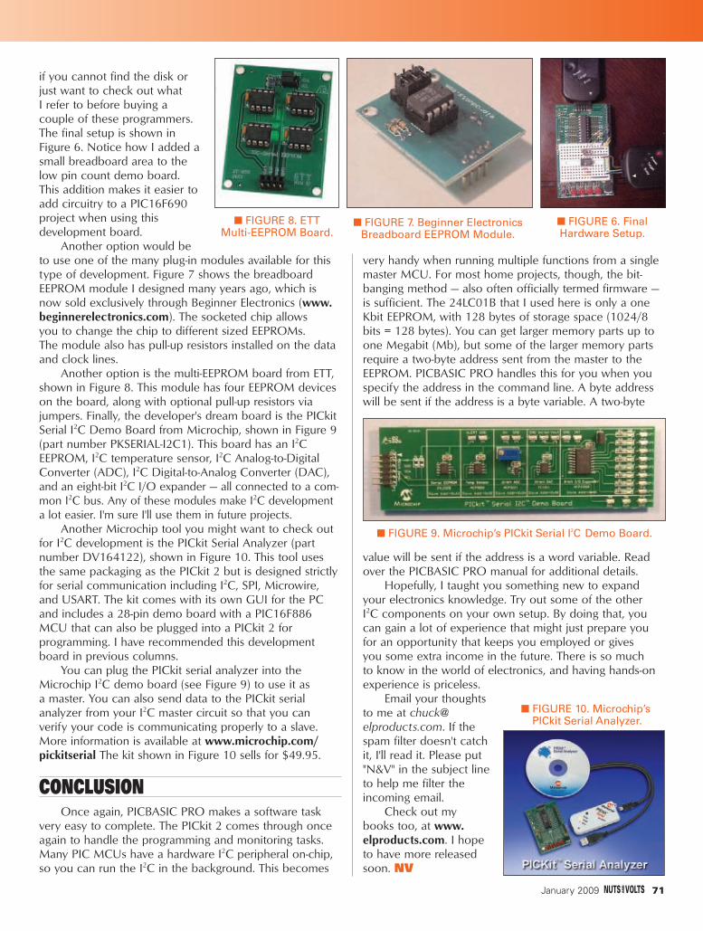
if you cannot find the disk orjust want to check out what I refer to before buying a couple of these programmers.The final setup is shown inFigure 6. Notice how I added asmall breadboard area to thelow pin count demo board. This addition makes it easier toadd circuitry to a PIC16F690project when using this development board.
Another option would beto use one of the many plug-in modules available for thistype of development. Figure 7 shows the breadboard EEPROM module I designed many years ago, which isnow sold exclusively through Beginner Electronics (www.beginnerelectronics.com). The socketed chip allows you to change the chip to different sized EEPROMs. The module also has pull-up resistors installed on the dataand clock lines.
Another option is the multi-EEPROM board from ETT,shown in Figure 8. This module has four EEPROM deviceson the board, along with optional pull-up resistors viajumpers. Finally, the developer's dream board is the PICkitSerial I2C Demo Board from Microchip, shown in Figure 9(part number PKSERIAL-I2C1). This board has an I2C EEPROM, I2C temperature sensor, I2C Analog-to-DigitalConverter (ADC), I2C Digital-to-Analog Converter (DAC),and an eight-bit I2C I/O expander — all connected to a com-mon I2C bus. Any of these modules make I2C developmenta lot easier. I'm sure I'll use them in future projects.
Another Microchip tool you might want to check outfor I2C development is the PICkit Serial Analyzer (partnumber DV164122), shown in Figure 10. This tool usesthe same packaging as the PICkit 2 but is designed strictlyfor serial communication including I2C, SPI, Microwire,and USART. The kit comes with its own GUI for the PCand includes a 28-pin demo board with a PIC16F886MCU that can also be plugged into a PICkit 2 for programming. I have recommended this developmentboard in previous columns.
You can plug the PICkit serial analyzer into theMicrochip I2C demo board (see Figure 9) to use it as a master. You can also send data to the PICkit serial analyzer from your I2C master circuit so that you can verify your code is communicating properly to a slave.More information is available at www.microchip.com/pickitserial The kit shown in Figure 10 sells for $49.95.
CONCLUSIONOnce again, PICBASIC PRO makes a software task
very easy to complete. The PICkit 2 comes through onceagain to handle the programming and monitoring tasks.Many PIC MCUs have a hardware I2C peripheral on-chip,so you can run the I2C in the background. This becomes
very handy when running multiple functions from a singlemaster MCU. For most home projects, though, the bit-banging method — also often officially termed firmware —is sufficient. The 24LC01B that I used here is only a oneKbit EEPROM, with 128 bytes of storage space (1024/8bits = 128 bytes). You can get larger memory parts up toone Megabit (Mb), but some of the larger memory partsrequire a two-byte address sent from the master to theEEPROM. PICBASIC PRO handles this for you when youspecify the address in the command line. A byte addresswill be sent if the address is a byte variable. A two-byte
value will be sent if the address is a word variable. Readover the PICBASIC PRO manual for additional details.
Hopefully, I taught you something new to expandyour electronics knowledge. Try out some of the other I2C components on your own setup. By doing that, youcan gain a lot of experience that might just prepare youfor an opportunity that keeps you employed or gives you some extra income in the future. There is so much to know in the world of electronics, and having hands-onexperience is priceless.
Email your thoughts to me at [email protected]. If thespam filter doesn't catchit, I'll read it. Please put"N&V" in the subject lineto help me filter theincoming email.
Check out my books too, at www.elproducts.com. I hopeto have more releasedsoon. NV
■ FIGURE 6. Final Hardware Setup.
■ FIGURE 8. ETT Multi-EEPROM Board.
■ FIGURE 9. Microchip’s PICkit Serial I2C Demo Board.
January 2009 71
■ FIGURE 7. Beginner ElectronicsBreadboard EEPROM Module.
■ FIGURE 10. Microchip’sPICkit Serial Analyzer.
GetStartedWithPICs-edited.qxd 12/8/2008 11:48 AM Page 71

As it turns out, I have plenty of USB Flash drives to plug into this month's project. I've mounted a
VDIP2 and a PIC18LF2620 on a perfboard and plumbedin some power. We're going to pick up where we left offlast time and put some C code together to access theinnards of that herd of USB Flash drives grazing on thebench in my office.
THE HOOKUPThanks to the PIC18LF2620's internal 8 MHz oscillator
block and its ability to operate at 3.3 volts, the interface
between the PIC18LF2620 and the VDIP2 is very simpleand clean. The VDIP2 is externally powered with fivevolts. The VDIP2's on-board 3.3 volt regulator supplies the internal 3.3 volts that the VDIP2's VNC1L IC requires.The Microchip MCP1700 has enough headroom tosupply up to 200 mA of 3.3 volt power to devicesexternal to the VDIP2. Take a look at Schematic 1 andyou'll see that the PIC and its supporting circuitry arepowered by this.
Note that the PIC18LF2620's EUSART and the VDIP2serial interface are directly coupled. We eliminate theneed to translate the serial port logic levels by poweringthe PIC with the same 3.3 volt power rail required by the VDIP2.
With the exception of the addition of some debugging LEDs attached to I/O pins RC3, RC4, and RC5,you have an abundance of PIC18LF2620 I/O to use
at your leisure. The VDIP2 multiplexes its communications lines with its I/O lines, depend-ing on the communications configuration youselect. We are configured for UART mode. The VDIP2 I/O lines AD0 and AD1 flex frombidirectional I/O to serial transmit and receive,respectively. Just in case we'll need to implement handshaking, I've pulled out theVDIP2's RTS (Request to Send) and CTS (Clearto Send) modem signals and terminated them at the PIC18LF2620's RC0 and RC1 I/O pins.
For those of you that are not communications experts, the DTE (DataTerminal Equipment) device raises the RTS signal when it wants to transmit. The DCE (DataCommunications Equipment) attached to theDTE sees the RTS signal and raises its CTS signal in response if all is clear for transmission.The DTE and DCE terms refer to a host computerwhich is the DTE device, and a modem which is
CHATTING UP A THUMBDRIVE
DESIGN■ BY FRED EADY
CYCLETHEADVANCED TECHNIQUES FOR DESIGN ENGINEERS
■ PHOTO 1. Building up the VDIP2 hardware was a walk inthe park. To keep things as simple as possible, I didn't includea five volt regulator circuit in the design. Instead, I optedto use an off-the-shelf regulated five volt DC wall wart. TheVDIP2 does all of the power supply work, including providingregulated 3.3 volt power for the PIC18LF2620.
I NEVER SEEM TO HAVE A USB FLASH DRIVE when I need one. So, when I saw this great deal on some 8GB DRIVEs, I picked up a couple for around theshop. I figured ITS SIZE was enough for just about any sneaker-net datatransfer job I'd have to do. Plus, the price was really good. Just last week I came across another Internet gotta-have-it USB flash drive deal. This time,I bit on some bargain 16GB flash drives.
72 January 2009
DesignCycleJAN-edited.qxd 12/9/2008 12:50 PM Page 72

the DCE device. In our project, the DTEdevice is VDIP2 while the PIC18LF2620is acting as the DCE device.
The VDIP2 interface hardware yousee in Photo 1 was assembled in lessthan an hour. The VDIP2 is mounted tothe perfboard using a high quality 40pin DIP socket. The same holds true forthe PIC18LF2620 except it is riding on a28 pin socket. I used wirewrap wire tomake all of the soldered point-to-pointelectrical connections.
Our VDIP2 hardware is simple dueto the fact that firmware rules the roostin the project. There's plenty of goodVDAP firmware residing within theVDIP2's VNC1L. So, let's return thefavor and put some worthy VDIP2 inter-face firmware into the PIC18LF2620.
CODING AN API FOR THE VDIP2
There is absolutely no doubt in my mind that you'll use your VDIP2/PIC18LF2620 combination in a projectthat is unique to you. With that thoughtin mind, I've decided to put together aset of firmware routines you can pickand choose from when applying theVDIP2 in your own projects. The goodnews is that you'll find the VDIP2 APIcode to be just as minimal and basic asthe interface hardware. The entireVDIP2 API is available as a downloadpackage from the Nuts & Volts FTP website (www.nutsvolts.com).
Let's start with the API base procedures and work our way up to the API main() function. The very firstfunction we will call from the main()function is the init() function:
The very first code that we will execute overrides the default power-uposcillator frequency of 1 MHz and setsthe PIC18LF2620 up with an 8 MHzprocessor clock. We could enable the processor clock 4X PLL to run at
T H E D E S I G N C Y C L E
J1
PO
WE
R
U1
VD
IP2
26
25
19
1
27
32
24
23
22
21
31
16
17
18
2 3 4 5 6 7 8 9
40
39
38
37
36
35
34
33
30
29
28
20
10
11
12
13
14
15
GN
D
AC
2
AD
4
NC
AC
3
3V
3
AC
1
AC
0
AD
7
AD
6
PG
#
AD
1
AD
2
AD
3
5V
0
5V
0
LE
D1
LE
D2
BD
7
BC
0
BC
1
5V
0
NC
3V
3
3V
3
BD
4
BD
3
BD
2
BD
1
BD
0
RS
#
AC
5
AC
4
AD
5
BC
2
BC
3
GN
D
GN
D
AD
0
GN
D
CTS
LE
D3
C1
.1uF
VR
ES
ET
RX
LE
D1
CT
S
R2
1K
RTS
C2
.1uF
TX
R6
330
5 V
OLTS
DC
R5
330
U2
PIC
18LF
2620
2345
21
22
23
24
25
26
27
28
11
12
13
14
15
16
17
18
109
1
67
819
20
RA
0
RA
1
RA
2
RA
3
RB
0/IN
T0
RB
1
RB
2
RB
3
RB
4
RB
5
RB
6/P
GC
RB
7/P
GD
RC
0
RC
1/C
CP
2
RC
2/C
CP
1
RC
3
RC
4
RC
5
RC
6/T
X
RC
7/R
X
RA
6
RA
7
MC
LR
RA
4/T
0C
KI
RA
5
GN
D
GN
D
VD
D
ICS
P C
ON
NE
CT
OR
1 2 3
4 5 6
1 2 3
4 5 6
LE
D2
3V
3
3V
3
R1
100
R3
10K
R4
330
RT
S
■ SCHEMATIC 1. The majority of the physical electronic partsused in this design are mounted on the VDIP2 printed circuitboard. Thanks to the VNC1L firmware, all of the hard work isshifted away from the hardware and is done with firmware.
// * INITIALIZE ROUTINE - Init clock and I/Ovoid init() {
OSCCON = 0x70; //set for 8 MHzPLLEN = 0; //no PLLTRISA = 0b01111111;TRISB = 0b11111111;TRISC = 0b10000001; //RTS is input
}
January 2009 73
DesignCycleJAN-edited.qxd 12/9/2008 12:51 PM Page 73

32 MHz if our application demanded it. The 8 MHz clockfrequency will provide plenty of computational throughputfor our VDIP2 application. Recall that the VDIP2 will issuean RTS signal to the PIC. So, RC0, which is the PIC's RTSinput, is set up as an input pin. The other PORTC input isthe RX (receive) line for the EUSART. Regardless of my manual manipulation of the direction of the TX (RC6) andRX (RC7) pins, the PIC18LF2620's EUSART automaticallysets the RC6 and RC7 pins for input or output as required.The remaining PORTC pins are defined as follows:
//* VDIP2 I/O DEFINITIONS
#define pRTS LATC0
#define pCTS LATC1
#define pRST LATC2
//* LED DEFINITIONS
#define LED3 LATC3
#define LED2 LATC4
#define LED1 LATC5
The PORTC VDIP2 pin definitions include a p prefixfor the modem control signals and the VDIP2 reset pin.LEDs occupy the remainder of the PORTC pins. I'veassigned LED1 as the heartbeat LED. The heartbeat LEDwill flash at a rate of 1 Hz, indicating that the VDIP2 APIcode is executing. The VDIP2 reset pin is a convenienceconnection that you'll find very useful. Without the VDIP2reset pin connection, you would have to power-down and power-up the VDIP2 every time you made a changeto the PIC firmware. Right now, we have no use for the PIC18LF2620's analog-to-digital (A-to-D) convertermodule or the comparators. So, let's turn all of that stuff off:
//* CONFIGURE A2D AND COMPARATORS
ADCON1 = 0b00001111; // All digital I/O
ADON = 0; // ADC off
CMCON = 0x07; // comparators off
Since the EUSART is our desired means of communi-cation with the VDIP2, we need to get the PIC18LF2620'EUSART online as quickly as possible. Once thePIC18LF2620's I/O ports are configured and the (A-to-D)converter and comparators are disabled, the code withinthe init() function fires up the PIC's EUSART with the following function call:
//* INITIALIZE EUSART
init_EUSART();
The code I use to service the PIC18LF2620's EUSARTis battle tested. All we have to do to put the interrupt-driven EUSART code to work for us is to specify a baudrate in the EUSART initialization code:
//* Init EUSART Function
void init_EUSART(void) {
SPBRG = 51; // 8MHZ = 51 FOR 9600BAUD
TRISC7 = 1; // receive pin
TRISC6 = 0; // transmit pin
TXSTA = 0x04; // highspeed baud, BRGH = 1
RCSTA = 0x80; // enable serial port
EUSART_RxTail = 0x00; //flush rx buffer
EUSART_RxHead = 0x00;
EUSART_TxTail = 0x00; //flush tx buffer
EUSART_TxHead = 0x00;
RCIP = 1; // rx interrupt = high pri
TXIP = 1; // tx interrupt = high pri
RCIE = 1; // enable rx interrupt
PEIE = 1; // enable all unmasked
// peripheral interrupts
GIE = 1; // enable all unmasked ints
CREN = 1; // enable EUSART1 receiver
TXIE = 0; // disable EUSART1 tx int
TXEN = 1; // transmitter enabled
}
Yep, I put my fingers on the TRIS (data direction) bitsof the EUSART's TX and RX pin yet again in theinit_EUSART() function. In reality, the TRISC7 and TRISC6statements in the init_EUSART() function could probablybe eliminated. However, when something works as well as this EUSART code has just as it is, leave it alone. Inaddition to enabling the EUSART interrupt mechanism, the code within the init_EUSART() function initializes thetransmit and receive buffer pointers which invalidates anyspurious data that resides in the buffers at power-up. The EUSART transmit and receive buffer area is defined inthe code that follows:
//* EUSART BUFFER DEFINITIONS
//1,2,4,8,16,32,64,128 or 256 bytes
#define EUSART_RX_BUFFER_SIZE 256
#define EUSART_RX_BUFFER_MASK (
EUSART_RX_BUFFER_SIZE - 1 )
// 1,2,4,8,16,32,64,128 or 256 bytes
#define EUSART_TX_BUFFER_SIZE 256
#define EUSART_TX_BUFFER_MASK (
EUSART_TX_BUFFER_SIZE - 1 )
unsigned char
EUSART_RxBuf[EUSART_RX_BUFFER_SIZE],
EUSART_TxBuf[EUSART_TX_BUFFER_SIZE];
unsigned char EUSART_TxHead,EUSART_TxTail,
EUSART_RxHead,EUSART_RxTail;
I've set the transmit and receive buffer sizes at theirmaximums of 256 bytes each. The transmit and receivebuffer masks are used to convert the EUSART bufferspaces into a pair of circular buffers. The EUSART circulartransmit and receive buffers are serviced by an interruptmechanism called EUSART_TIMER1:
74 January 2009
DesignCycleJAN-edited.qxd 12/9/2008 12:51 PM Page 74

//* INTERRUPT HANDLER ROUTINE
void interrupt EUSART_TIMER1(void) {
char usart_data,tmphead,tmptail;
The temporary transmit and receive buffer pointerbytes in the interrupt handler char declaration. Theusart_data byte is used to hold the incoming bytes that are removed from the EUSART's hardware buffer. TheTIMER1 portion of the PIC18LF2620 interrupt handler isrepresented by code that "ticks" every millisecond:
if((TMR1IF && TMR1IE)) {
TMR1IF = 0;
TMR1H = 0xF8;
TMR1L = 0x31;
++tmsecs1;
if(++imsecs1 == 1000) {
imsecs1 = 0;
++isecs1;
++tsecs1;
LED1 ^= 1;
}
}
Every time that TIMER1 overflows, it is reloaded withan integer that causes the timer to overflow again in onemillisecond. The milliseconds are collected into secondsand are used to provide timing for the millisecond andsecond timer functions. As you can see in the TIMER1interrupt handler code, LED1 is toggled every 1,000 ms or every second.
Every time the EUSART signals that a character is captured in its hardware receive buffer, the interrupt handler code fetches the received byte from the EUSART'shardware buffer and stores it in the next available byte slotof the receive buffer. The idea behind the circular bufferscheme is to never let the head pointer value of the buffercatch up to the tail pointer value of the buffer. I've neverhad to execute the error statements in this receive interrupt handler code:
if(RCIF) {
usart_data = RCREG; //read received data
// calculate new buffer index
tmphead = ( EUSART_RxHead + 1 ) &
EUSART_RX_BUFFER_MASK;
EUSART_RxHead = tmphead; // store new index
if ( tmphead == EUSART_RxTail ) {
//ERROR! Receive buffer overflow
status.buf_ovrf = 1;
}
// store received usart_data in buffer
EUSART_RxBuf[tmphead] = usart_data;
}
The transmit interrupt handler code is only used bythe sendchar() function. When the sendchar() function iscalled, the outgoing byte is placed in the PIC18LF2620'stransmit buffer and the transmit interrupt enable bit isactivated. The interrupt handler code keys on the transmitinterrupt bit, retrieves the byte from the transmit buffer,and stuffs it into the EUSART's hardware transmitbuffer. The EUSART — seeing a byte in its TXREG register— sends that byte along its way. Like the EUSART receiveinterrupt handler code, the transmit interrupt handlercode declares the associated buffer empty when thebuffer head pointer is equal to the tail buffer pointer. Ifmore than one character is waiting in the PIC’s transmitbuffer, the transmit interrupt handler code will attemptto transmit until the transmit buffer is found to beempty. Here's what the transmit interrupt handler code looks like:
if(TRMT) {
//check if all usart_data is transmitted
if ( EUSART_TxHead != EUSART_TxTail ) {
//calculate new buffer index
tmptail = ( EUSART_TxTail + 1 ) &
EUSART_TX_BUFFER_MASK;
EUSART_TxTail = tmptail; //save new idx
TXREG = EUSART_TxBuf[tmptail]; //send it
}
else {
TXIE = 0; // disable TX interrupt
}
}
The CharInQueue(), recvchar(), and sendchar() functions interact with the interrupt handler routines we've just discussed. We examined the inner workings of the CharInQueue(), recvchar(), and sendchar() functionsin the previous installment of Design Cycle.
After powering up the PIC18LF2620's EUSART, weturn our attention to TIMER1:
//* CONFIGURE AND START TIMER1,
//* SET TO OVERFLOW EVERY 1mS
//F831 = 8MHz
//E0C1 = 32MHz
TIMER1OFF;
T1CON = 0b00000000;
TMR1H = 0xF8;
TMR1L = 0x31;
TIMER1ON;
Basically, we let TIMER1 do its thing with the processor clock unhindered by prescalers. Just in case you want to put the pedal to the silicon, I've included theTIMER1 32 MHz clock value in a comment of the TIMER1initialization code.
At this point, we can open the gate and let the horses run:
T H E D E S I G N C Y C L E
January 2009 75
DesignCycleJAN-edited.qxd 12/9/2008 12:52 PM Page 75

//* CONFIGURE EXTERNAL INTERRUPTS
enable_TMR1int;
enable_GLOBALint;
The PIC18LF2620 interrupt engine is started and theinterrupt handler code begins to process the incominginterrupts. The final initialization acts we perform tell theVDIP2 that it can transmit to the PIC18LF2620 EUSART, to make sure that the VDIP2 is not in a forced reset, extinguish the remaining LEDs (LED1 is flashing), and set up the operational mode:
//* INITIALIZE I/O
pCTS = 0;
pRST = 1;
LED2 = OFF;
LED3 = OFF;
current_mode = waiting_for_work;
sdelay1(1);
}
The operational modes are enumerated as follows:
enum {
waiting_for_work, //0
disk_ready, //1
file_create, //2
file_write, //3
file_end, //4
waiting_for_remove //5
};
Using enum is just a fancy way of assigning eachoperational mode to a number. Using names associatedwith numbers makes the code a bit easier to read andunderstand.
Now that we've initialized the PIC18LF2620, we'reready to converse with the VDIP2. The first order ofbusiness is to bring our VDIP2 VDAP firmware up todate. There are a couple of ways to perform the VNC1Lupdate. The bootloader method requires some hardwareand a bit of coding to get the latest level of VDAP disk
and peripheral firmware into the VNC1L IC.The second firmware upgrade choice involves
initializing the VDIP2 and plugging in a Flash drive thatcontains the updated firmware file in its root directory.Thus far, we've almost written just enough code to initialize the VDIP2 using the PIC18LF2620.
So, we'll update our VDIP2 using what the Vinculumengineers call the Reflash method, which utilizes a specialfile loaded in the root directory of a Flash drive. However,before we can reflash our VNC1L, we still have a coupleof API routines to construct.
First, let's build a VDIP2 reset function:
//* VDIP2 RESET
void vreset(void) {
pRST = 0;
mdelay1(100);
pRST = 1;
}
The logic associated with the VDIP2 reset pin is active low. So, to reset the VNC1L that rides on theVDIP2 printed circuit board, all we need to do is pull theVDIP2 reset pin low for a period of time and then return it to a logical high state. To pull off the VDIP2 reset, weneed a supporting timing function:
#define mdelay1(msecdelay) TIMER1OFF; \
TMR1IF = 0; \
imsecs1 = 0; \
tmsecs1 = 0; \
TIMER1ON; \
while(tmsecs1 < msecdelay);
The mdelay1() delay routine is really not a function. It is a C macro. As you can see the inner workings of the mdelay1() macro above, TIMER1 is disabled, theTIMER1 interrupt handler values are cleared, the timer is restarted, and time is marked in place until the numberof milliseconds in the macro argument have passed.
The next bit of code we need to assemble to initializethe VDIP2 is a synchronization function. Let's examine theVDIP2 synchronization I've written snippet by snippet:
//* SYNC WITH VINCULUM
76 January 2009
■ SCREENSHOT 1. The very first byte of the receive buffer is not used initially due to the way that its mask manipulatesthe receive buffer pointer. However, you can easily pick out the echo responses in this capture.
■ SCREENSHOT 2. At this point, we've successfully initialized the VDIP2 and synchronized to it. The message you see inthe capture says it all.
DesignCycleJAN-edited.qxd 12/9/2008 12:53 PM Page 76

char sync(void) {
char rc;
rc = 0;
sync_loops = 0; //init sync loop counter
status.E = 0; //clear E received status
status.e = 0; //clear e received status
cleaner(); //clear receive buffer
The VDIP2 sync() function sends an E and an e in succession to the VDIP2 with each letter followed by acarriage return (0x0D). The VDIP2 echoes the receivedcharacter indicating that is in "in sync" with thePIC18LF2620 and its firmware. The results of each echooperation are recorded in a status bit which is defined in a structure of bits:
typedef struct{
char E:1;
char e:1;
char buf_ovrf:1;
}SSTATS;
SSTATS status;
Note that the EUSART receive buffer overflow bit isalso defined in the status bit structure. As we build uponthe API, bits will be added to the status structure and theenum list as required.
You're probably wondering what the cleaner() functiondoes for us. The cleaner() function is not necessary to theoperation of the VDIP2 system. This function is actuallyjust a convenience function that is used to clear the PIC’sEUSART transmit and receive buffers. The "cleaner" alsoresets the buffer head and tail pointers to indicate that thebuffers are empty. I used this function quite a bit whiledebugging the API code:
//* CLEAR THE RECEIVE BUFFER
void cleaner(void) {
unsigned int x;
for(x=0;x<EUSART_RX_BUFFER_SIZE-1;++x)
EUSART_RxBuf[x] = 0;
for(x=0;x<EUSART_TX_BUFFER_SIZE-1;++x)
EUSART_TxBuf[x] = 0;
EUSART_RxTail = 0x00; //flush rx buffer
EUSART_RxHead = 0x00;
EUSART_TxTail = 0x00; //flush tx buffer
EUSART_TxHead = 0x00;
}
Syncing up with the VDIP2 is a straightforwardprocess. The PIC18LF2620 is instructed to send an Efollowed by a carriage return and wait for a response.
The VDIP2 should respond with the sequence of characters it received, which are an E followed by a carriage return. If the correct characters are received bythe PIC, thestatus.E bit is set.
The process is repeated until the correct charactersequence is received or the attempt counter overflows.Once the initial E sequence is successful, an identicaltransmission/reception process is executed using an e. Ifthe e echo sequence is successful, the status.e bit is set.The E echo and sync code snippet looks like this:
do{
cmd_echo('E'); //send E
sync_loops++; //inc sync loop counter
bytein_ptr = 0; //init rx char pointer
//wait for character
while((!CharInQueue()));
//get 2 bytes
do{
bytein[bytein_ptr++] = recvchar();
}while(CharInQueue());
//check for echoed E and carriage return
if(bytein_ptr) {
if ((bytein[0] == 'E') &&
(bytein[1] == 0x0D)) {
status.E = 1;
}
else {
mdelay1(100);
}
}
}while((status.E == 0) &&
(sync_loops < 0xFF));
If the status.E bit gets set, all is good and permissionto proceed with the execution of the e echo and synccode is given:
if (status.E) {
do{
cmd_echo('e'); //send e
sync_loops++; //inct sync counter
bytein_ptr = 0; //init rx char ptr
//wait for character
while((!CharInQueue()));
//get 2 bytes
do{
bytein[bytein_ptr++] = recvchar();
}while(CharInQueue());
//check for echoed e and CR
if(bytein_ptr) {
if ((bytein[0] == 'e') &&
January 2009 77
T H E D E S I G N C Y C L E
DesignCycleJAN-edited.qxd 12/9/2008 12:54 PM Page 77
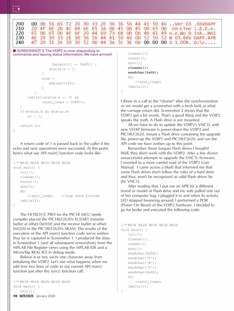
(bytein[1] == 0x0D)) {
status.e = 1;
}
else {
mdelay1(100);
}
}
}while((status.e == 0) &&
(sync_loops < 0xFF));
}
if(status.E && status.e)
rc = 1;
return rc;
}
A return code of 1 is passed back to the caller if theecho and sync operations were successful. At this point,here's what our API main() function code looks like:
//* MAIN MAIN MAIN MAIN MAIN
void main() {
init();
cleaner();
vreset();
sync();
do{
++sync_loops; //loop here forever
}while(1);
}
The HI-TECH C PRO for the PIC18 MCU family compiler placed the PIC18LF2620's EUSART transmitbuffer at offset 0x0100 and the receive buffer at offset0x0200 in the PIC18LF2620's SRAM. The results of theexecution of the API main() function code we've writtenthus far is captured in Screenshot 1. I produced the datain Screenshot 1 (and all subsequent screenshots) from theMPLAB File Register views using the MPLAB IDE and aMicrochip REAL ICE in debug mode.
Believe it or not, we're one character away from initializing the VDIP2. Let's see what happens when weadd tese two lines of code to our current API main() function just after the sync() function call:
//* MAIN MAIN MAIN MAIN MAIN
void main() {
init();
cleaner();
vreset();
sync();
cleaner();
sendchar(0x0D);
do{
++sync_loops;
}while(1);
}
I threw in a call to the "cleaner" after the synchronizationso we would get a screenshot with a fresh look at whatthe carriage return did. Screenshot 2 shows that theVDIP2 got a bit wordy. That's a good thing and the VDIP2speaks the truth. A Flash drive is not mounted.
All we have to do to update the VDIP2's VNC1L withnew VDAP firmware is power-down the VDIP2 andPIC18LF2620, mount a Flash drive containing the upgradefile, power-up the VDIP2 and PIC18LF2620, and run theAPI code we have written up to this point.
Remember those bargain Flash drives I bought? Well, they don't work with the VDIP2. After a few dozenunsuccessful attempts to upgrade the VNC1L firmware, I resorted to a more careful read of the VDIP2 UserManual. I came across a blurb that informed me thatsome Flash drives don't follow the rules of a hard driveand thus, won't be recognized as valid Flash drives by the VNC1L.
After reading that, I put out an APB for a differentbrand or model of Flash drive and my wife pulled one outof her computer bag. I plugged it in and when its activityLED stopped bouncing around, I performed a POR (Power On Reset) of the VDIP2 hardware. I decided to go for broke and executed the following code:
//* MAIN MAIN MAIN MAIN MAIN
void main() {
init();
cleaner();
vreset();
sync();
sendchar(0x0D);
sendchar('F');
sendchar('W');
sendchar('V');
sendchar(0x0D);
do{
++sync_loops;
}while(1);
}
78 January 2009
■ SCREENSHOT 3. The VDIP2 is now responding tocommands and issuing status information. We have arrived!
DesignCycleJAN-edited.qxd 12/9/2008 12:54 PM Page 78

Screenshot 3 tells the story. The alternate Flash driveworked. The reset operation caused the version to bedisplayed, followed by an on-line indication. Next, youcan see the sync characters being acknowledged. Thecarriage return that I issued after the sync() function callforced the NO Disk message.
Here's where I sucked it up and issued a real VDIP2monitor command. The firmware version of the VNC1L is returned when the character set FWV followed by a carriage return is issued to the VDIP2's monitor. The version information begins with the characters MAIN inScreenshot 3. Note that a prompt is issued even though a Flash drive was not mounted.
ONE MORE HURDLEEverything has worked as designed up to this point.
However, we have one more test to perform before moving on to put the rest of the meat into the API. Here's the code we'll execute:
//* MAIN MAIN MAIN MAIN MAIN
void main() {
init();
cleaner();
vreset();
sync();
sendchar(0x0D);
do{
++sync_loops;
}while(1);
}
I'll run the code without mounting a Flash drive. Once theVDIP2 indicates that it is initializedand synced (the on-board VDIP2LEDs stop flashing and extinguish), I'll mount a Flash drive. Follow along referencing Screenshot 4 and let'ssee if we're ready to start reading and writing to the Flash drive.
All of the monitor messages upthrough No Disk in Screenshot 4were issued immediately after power-up with no Flash drive mounted. The monitor messageDevice Detected P2 says that a Flash drive was detected on USB Port 2. This is good as the Device
Detected P2 message was sent when I mounted the Flashdrive. The No Upgrade monitor message is telling us that the upgrade file (FTRFB.FTD)was not found in the root directory of the newly mounted Flash drive. Most importantly, the D:\> promptindicates that the Flash drive I mounted is read/write compatible with the VDIP2. Welcome to Flash Drive City!
DOWNLOAD YOUR COPY OFTHE API CODE
You have witnessed what it takes to issue a command. Therefore, you won't have any problems deciphering the C source in the download package that makes up the VDIP2 API. I've written the VDIP2 API to include Disk Commands, Monitor ConfigurationCommands, and I/O Commands. I've also included aexample file read/write application in the download package.
Using the VDIP2 API coupled with the VDIP2 hardware interface we've designed and built, you shouldhave no problems including USB Flash drives in yourDesign Cycle. NV
January 2009 79
DOWNLOAD the HIDmaker FS Test Drive today!
www.TraceSystemsInc.com
301-262-0300
NEW! HIDmaker FS for Full Speed FLASH PIC18F4550
Creates complete PC and Peripheralprograms that talk to each other overUSB. Ready to compile and run!
• Large data Reports• 64,000 bytes/sec per Interface• Easily creates devices with multiple
Interfaces, even multiple Identities!• Automatically does MULTITASKING• Makes standard or special USB HID
devices
NEW! “Developers Guide for USB HIDPeripherals” shows you how to makedevices for special requirements.
Both PC and Peripheral programsunderstand your data items (even oddsized ones), and give you convenientvariables to handle them.
PIC18F Compilers: PICBASIC Pro,MPASM, C18, Hi-Tech C.
PIC16C Compilers: PICBASIC Pro,MPASM, Hi-Tech C, CCS C.
PC Compilers: Delphi, C++ Builder,Visual Basic 6.
HIDmaker FS Combo: Only $599.95
T H E D E S I G N C Y C L E
■ SCREENSHOT 4. Our VDIP2 and PIC18LF2620 are playingnicely together. Now that I've found a compatible Flashdrive, we can move on to complete the API coding task.
DesignCycleJAN-edited.qxd 12/9/2008 12:55 PM Page 79

Iknow just enoughFrench to be dangerous,so on a visit to Paris, I
insisted on using the regular menu and gotsome very strange meals.After a few such mishaps, I discovered that they usually had an Englishmenu hidden away for lesbarbares so I started usingthat one and still got somevery strange meals. C'estla Vie. In this month’sworkshop, after learningmore about C syntax for
decision making, we are going to write a menu navigationsystem similar in concept to the one on your cell phone,but for the Butterfly using its LCD and joystick. Importantsafety tip: Make sure you understand the concepts inWorkshops 1 through 5 before slamming your head intothis article.
C Control FlowStatements and Blocks
Expressions such as PORTD = ~i or j -= 128become statements when they are followed by a semicolon.
PORTD = ~i;
j -= 128;
The semicolon terminates the statement.
Tale of a BugI wrote the following statement:
while(QuarterSecondCount < 17600);
QuarterSecondCount = 0;
then decided that the 17600 wait count was too long, so Ichanged it to 2200:
while(QuarterSecondCount < 2200) //17600);
QuarterSecondCount = 0;
But I wanted to remember the 17600 in case I everneeded it again, so I commented it out and added the newvalue. Do you see a problem here?
Well, what I meant to say was:
while(QuarterSecondCount < 2200);
QuarterSecondCount = 0;
which is two statements: the first waits while an interrupt running in the background incrementsQuarterSecondCount, and once that is finished theQuarterSecondCount is set to zero. What the compilersaw was:
while(QuarterSecondCount < 2200)
QuarterSecondCount = 0;
But the compiler doesn't see anything following the //comment delimiter. See the problem yet?
Well, how about the equivalent statement:
while(QuarterSecondCount < 2200)
QuarterSecondCount = 0;
I had accidentally 'commented out' the terminatingsemicolon from the first statement. The compiler doesn'tknow about the line breaks; all it sees is a single statement which says that while QuarterSecondCount is less than 2200, set QuarterSecondCount to 0. So, each time the interrupt incremented QuarterSecondCount,this statement set it back to zero. One lousy semicolongone and everything changes!
This is the kind of bug that after spending X amount oftime locating, you carefully hide it from your boss lest shethink you are stupid or careless or both. Fortunately, I ammy own boss, so I've learned to live with my stupid andcareless employee. (I fired myself once, but that just didn'twork out.)
Compound statements are made by enclosing agroup of statements or declarations in a block delimited by braces '{' and '}'. This causes the compiler to handlethe block as a unit.
If-else and else-If
We can make decisions using the if-else statement:
by Joe Pardue
■■ FFIIGGUURREE 11.. LLéé bbaarrbbaarree eett lléé mmeennuu..
PART 6: A Menu NavigatorGet started now with this series!
Joe’s book & kit are available in our
webstore at wwwwww..nnuuttssvvoollttss..ccoomm
80 January 2009
Pardue6-edited.qxd 12/8/2008 10:04 AM Page 80

if (expression1)
{
statement1a;
statement1b;
}
else if(expression2)
{
statement2a;
statement2b;
}
else
{
statement3a;
statement3b;
}
In this case, each expression will be evaluatedsequentially looking for the first non-zero (true) expressionand if they all equal 0 (false), we do the final block ofstatements. You can omit the final else statement if youwant to do nothing if all the expressions are 0 (false). Note also that only the first true expression is used; ifexpression1 is true and expression2 is also true, it won'tmatter because the code will exit the if-else after the firsttrue case. We could use this construction to write a blockof code for interpreting joystick input positions:
if(input == KEY_UP) keyUP();
else if(input == KEY_DOWN) keyDOWN();
else if(input == KEY_LEFT) keyLEFT();
else if(input == KEY_RIGHT) keyRIGHT();
else if(input == KEY_PUSH) keyPUSH();
else keyERROR();
This says: If the input is equal to KEY_UP, then callthe keyUP() function. If the first line is true, then the rest ofthe statements are skipped. If the first line isn't true, theneach line is evaluated sequentially until a true expressionis found or it calls the final 'else' keyError() function.
Switch
The 'if else' construction limits us to expressions thatare either true or false. If we want to make decisions usingexpressions that can have any numeric result, we use theswitch statement that selects an expression with resultsequal to a specified constant.
We can redo the if-else block used in the joystickinterrupt example using a switch statement as follows:
switch(input){
case KEY_UP:
keyUP();
break;
case KEY_DOWN:
keyDOWN();
break;
case KEY_LEFT:
keyLEFT();
break;
case KEY_RIGHT:
keyRIGHT();
break;
case KEY_PUSH:
keyPUSH();
break;
default:
keyERROR();
break;
}
This works just like the if-else block. The 'break' statement causes an immediate exit from the switch block— there is no need to check the rest as we have foundour case. If you want to continue evaluating cases againstthe input, leave out the break and the next statements willbe looked at. You can let cases fall through, which can behandy in circumstances such as evaluating character inputwhere you don't care if the character is a capital or lowercase letter, or perhaps you want the same response for arange of integers:
switch(input){
case 'a' :
case 'A' :
doaA();
break;
case 'b' :
case 'B' :
dobB();
break;
case '0' :
case '1' :
case '2' :
case '3' :
gofer0123();
break;
case '4' :
case '5' :
case '6' :
case '7' :
gofer4567();
break;
default:
doDefault();
break;
}
Switch statements are error prone and a frequentsource of head boinking bugs (one where you boink your head for being dumb enough to leave out a breakstatement). The break after default: isn't even necessary,but is recommended (by K&R) as a good practice to help you remember to use it when you add a statement
SMILEY’S WORKSHOP ☺
January 2009 81
Pardue6-edited.qxd 12/8/2008 10:04 AM Page 81

to the end of the list.
Loops - While, For, and Do-while
We've been using while for a while (har!).
while(expression)
{
// Do stuff while expression is true
}
While will repeat the associated statement or block aslong as the expression is true. The code fragment:
int i;
while( i < 128)
{
PORTD = i;
_delay_loop_2(30000);
i = i*2;
}
This does the same thing as the following for loop:
int i;
for(i = 1; i < 128; i = i*2)
{
PORTD = i;
_delay_loop_2(30000);
}
The for loop is constructed as follows:
for(expresson1; expression2; expresson3)
{
// Do stuff
}
Usually, expression1 and expression3 are assignments orfunction calls and expression2 is a test of some sort. Theexpressions can be any expression including the emptyexpression which is nothing followed by a semicolon:
for(;;)
{
// Do stuff forever
}
This is an alternative way to do the while(1) eternalloop. You can accomplish the same goal using either whileor for statements. Generally, it is clearer to use for loopswith a simple initialization and incrementing such as:
for(i = 1; i < 128; i = i*2)
{
// Do stuff while 'i' less than or equal
128
}
It's really a matter of personal preference though mostC dudes will want to smack you around a little if you don'tdo it their way. While and for loops test for the terminationcondition before running the block; 'do while' runs theblock first before checking the expression, insuring thatthe block will be run at least once:
do
{
// Do stuff at least once
}
while(expression);
A Butterfly Menu SystemIf you still have the box your Butterfly came in,
you can see the full Butterfly menu laid out for you (or you can find it in Figure 2-2 Application Menu in theButterfly_UserGuide.pdf in the workshop6.zip file on theNuts & Volts website). For this project, we will recreateroughly the first half of the Butterfly menu system (Figure2: Partial Butterfly menu). Look at this figure for a whileand think about how you might do this task based on theC syntax flow control discussion above.
We will make heavy use of the switch statement forcreating our menu system. For our hardware, we will use the Butterfly LCD to display the menu text and thejoystick to navigate around the menu and make menu
82 January 2009
■■ FFIIGGUURREE 22.. PPaarrttiiaall BBuutttteerrffllyy mmeennuu..
Pardue6-edited.qxd 12/8/2008 10:05 AM Page 82

item selections. The joystick gives us the option of 'moving' the menu up or down to view main menu items,left or right to view submenu items, or press to the centerto select an item. We will hide all the details of using theLCD and joystick in the smws6 object module that I've precompiled for you and put in the C:\smws6\default directory so that you don't have to blow your mind lookingat the source code for a lot of LCD and joystick supportfunctions that are a bit advanced and messy (you don'tneed to understand them to understand menus). I stronglysuggest that you copy the entire source directory (in workshop6.zip) and keep a virgin copysomewhere convenient so that as you mess with these ideas you can go back to a version that works.
The original Butterfly source code uses some intense C ideas toaccomplish this task, but we will use something a bit clearer for earlylearning purposes. More advanced programmers will react to this codemuch like the waiter in Figure 1. Westart off in an initial menu state which, in our case, is state00 (AVR BUTTERFLY). After running the action function for this state:menuState00Func(), we enter an eternal loop and check for input fromthe UART or the joystick buttons. (We won't discuss the UART functions— they were useful for debugging and I left them in.) When thecheckJoystick() function tells us thatthere is a button press pending, wecall the parseJoystickInput() function.
int main(void)
[As an aside, the show("this") 'function'is actually a hidden macro that outputsthe "this" string on both the UART andthe LCD.] We will keep the currentstate in 'menuState':
// what state are we in?
volatile uint8_t menuState;
This is a global eight-bit unsigned(uint8_t) variable declared as volatileso that the compiler knows it maychange unpredictably and won't try to second-guess you and eliminateit if it thinks it isn't really being used (compilers are also a lot like the waiter in Figure 1).TheparseJoystickInput function is a 17case switch statement that calls the
state function for the current menuState variable:
void parseJoystickInput()
{
switch(menuState)
{
case 0:
state00();
break;
case 1:
state01();
January 2009 83
Pardue6-edited.qxd 12/8/2008 10:05 AM Page 83

break;
case 2:
state02();
break;
// Cases 3 through 16 deleted to save space
case 17:
state17();
break;
default:
// TODO: DEAL WITH ERROR
break;
}
}
Note that this function is not related to any particularjoystick button; it simply calls the state function for the current state if there is joystick input. The state functionthat gets called will look at the global variable 'joystickInput'value and act accordingly.
We will navigate the menu states by using the joystickbuttons: UP, DOWN, LEFT, and RIGHT. We will decide ifan action other than moving about the menu states shouldbe done by looking at the joystick button PUSH. So, if weare in a given menu state and we get any of the movementstates, we move if there is another state in that direction(and change the menu state to the new state) or we ignoreit if there is no valid state in that direction (no change tothe menu state). If we see that the joystick button is PUSH,we keep the state the same, but process the PUSH actionspecified for that state. If, at this point, your personal stateis thinking about tearing up the magazine and finding aFrench waiter to punch out, try to bear with this for a while.Read the code snippets below and reread this section ifnecessary. It may take a while to get your head aroundthese concepts. We will also keep track of whether the joystick button has been pressed to the center, which wewill use to take actions not related to menu state changes:
// do we need to something?
volatile uint8_t keyPush;
To repeat: When we get a new joystick button state,we can do one of two things: change the menu state ortake an action for the current menu state.
Let's look at a single state and see what can happen.Look at state03 (CLOCK) in Figure 2 and think about whathappens next when the joystick button changes to:
1. Up - Do nothing.2. Down - Change to state07.3. Left - Change to state02.4. Right - Change to state04.5. Push - Set keyPush equal true.
When we change menu states, we will call a functionwith the actions for that new state. If the button is not amenu state change but is PUSH, we will call the action
function for the current menu state. We can write this as:
void state03()
{
switch(joystickInput)
{
case KEY_UP:
// Do nothing
break;
case KEY_DOWN:
// Change to menu state07
menuState = 7;
menuState07Func();
break;
case KEY_LEFT:
// Change to menu state02
menuState = 2;
menuState02Func();
break;
case KEY_RIGHT:
// Change to menu state04
menuState = 4;
menuState04Func();
break;
case KEY_PUSH:
// Call this menu state funcion
// with keyPress =
keyPush = 1; //true
// take action for this state
menuState03Func();
break;
default:
// Do nothing
break;
}
joystickInput = KEY_INVALID;
}
As usual, this is just an overview of the actual code.You can play with it by getting Workshop6.zip fromwww.smileymicros.com or the Nuts & Volts website atwww.nutsvolts.com. We are doing something differentthis time. Instead of using a library for the LCD and joystickfunctions, we are using an object module (smws6.o) thatmust be located in the C:\MenuTest\default directory sothat the MenuTest project can find it.I avoided mentioning'state machine' up to this point since these two words —when connected — tend to send folks running for the exits.But, guess what? You just studied a state machine andyour head didn't explode (I hope). Yes, state machines areoften the topics of computer science doctoral dissertations,but they can also be as simple as a switch statement.
We have three more workshops that will complete ourstudy of introductory C syntax, then we will assume thereader already knows enough C and move on to somehardware oriented projects. Next month, we will continuewith more C syntax and build a Butterfly alarm clock. NV
Joe Pardue can be reached at wwwwww..ssmmiilleeyymmiiccrrooss..ccoomm
84 January 2009
Pardue6-edited.qxd 12/8/2008 10:11 AM Page 84

January 2009 85
Page 85.qxd 12/10/2008 8:23 AM Page 85

“EDITOR’S PICKS” 2008 CD-ROM
The Nuts & Volts WEBSTORE
ELECTRONICSBBuuiilldd YYoouurr OOwwnn EElleeccttrroonniiccss
WWoorrkksshhoopp By Thomas Petruzzellis
YOUR DREAM ELECTRONICS LABIS WAITING INSIDE!
This value-packedresource provideseverything neededto put together afully functioninghome electronicsworkshop! Fromfinding space tostocking it withcomponents to put-ting the shop intoaction — building, testing, and trou-bleshooting systems — popular electronicsauthor Tom Petruzzellis’ Build Your OwnElectronics Workshop has it all! And the bestpart is, this book will save you money, bigtime! Reg $$2299..9955 SSaallee PPrriiccee $$2244..9955
GGeettttiinngg SSttaarrtteedd wwiitthh PPIICCssA Collection of 2006 Nuts & Volts
Magazine Articles By Chuck Hellebuyck
In the January 2006 Nuts & Volts Magazine,Chuck Hellebuyck started a column titled“Getting Started with PICs” thatfocused on the beginner. It became a popular column andcontinues in Nuts & VoltsMagazine today.Many readers missedthe early columns sothis book containsthe original 2006articles compiledinto a book for easy reference.$$2299..9955
We have ove r 170 r e lated t i t les in our webs tore!!
BBlluu--rraayy DDiisscc DDeemmyyssttiiffiieeddby Jim Taylor, Michael Zink,Charles Crawford, ChristenArmbrust Pub Date:November 10, 2008The Latest Tips andTechniques forGetting the Maximumfrom Blu-rayTechnology.
Written by a team of experts with a widerange of experience in DVD and high-definition production, this thorough,skill-building guide details Blu-ray's manyfeatures, formats, and applications.$$5599..9955**
FFuunnddaammeennttaall EElleeccttrriiccaall aannddEElleeccttrroonniicc PPrriinncciipplleess
by C R Robertson TThhiirrdd EEddiittiioonn
A thorough introductionto electrical and electronicengineering at Level 3.Fundamental Electrical andElectronic Principles coversthe essential principles thatform the foundations forelectrical and electronicengineering courses.Thecoverage of this new edition has been carefully brought in line with the core unit'Electrical and Electronic Principles' of the 2007 BTEC National Engineering specification from Edexcel. $$3355..9955
Electronics Projects for Dummies
Whether you're new to hands-on electronics or you want to gently introducesomeone else to the art, this book providesthe information and instruction you need,
from how to read a circuit diagram tobuilding some cool circuits.
$$2244..9955
46 Science Fair Projects for the Evil Genius
A perfect starter text for budding scientists, this approachable and fun bookhas something for everyone. The projects
are both affordable and intellectually challenging
$$1199..9955
GGeettttiinngg SSttaarrtteedd iinn EElleeccttrroonniiccss by Forrest M. Mims III
Author Forrest Mims teaches you thebasics, takes you on atour of analog and digitalcomponents, explainshow they work, andshows you how they arecombined for variousapplications. Includes circuit assembly tips and100 electronic circuitsand projects you canbuild and test. Forrest M. Mims, III, haswritten dozens of books, hundreds of articles, invented scientific devices, andloves to share his knowledge with eagerstudents! $$1199..9955
Editor Bryan Bergeron’s recommended reads.Find these and many more great titles in the NUTS & VOLTS Webstore!
BBeeggiinnnneerr''ss GGuuiiddee ttoo EEmmbbeeddddeedd CCPPrrooggrraammmmiinngg CCoommbbooby Chuck Hellebuyck
Book and Kit can be purchased separately.The C language has been covered in manybooks but none as dedicated to the embedded microcontroller beginner.Through his down-to-earth style of writing,Chuck Hellebuyck delivers a step-by-stepintroduction to learning how to programmicrocontrollers with the C language.The PICkit 2 Starter Package is used for allthe projects in the book and includes theHI-TECH PICC-Lite Compiler and aPIC16F690.RReegg $$8899..9955 SSaallee $$8866..9955
86 January 2009
NNEEW!W!
TThhee 22000088 CCDD--RROOMM hhaass aarrrriivveedd!!1122 iissssuueess oonn 11 CCDD,,
wwiitthh aallll yyoouurr ffaavvoorriittee aarrttiicclleess,,pprroojjeeccttss,, mmeeddiiaa ddoowwnnllooaaddss,, aanndd
aaddvveerrttiisseerrss..
BestBest
Seller
Seller
NVWebstoreJan090.qxd 12/10/2008 11:07 AM Page 86

EEnnccyyccllooppeeddiiaa ooff EElleeccttrroonniiccCCiirrccuuiittss,, VVoolluummee 77
by Rudolf F. Graf / William SheetsPublish Date: August 31, 1998
An extensive libraryof 1,000 circuits fromthe bestselling, seven-volume Encyclopediaof Electronic Circuits. Avirtual treasurehouse.An invaluable referencetool for everyhobbyist, technician,student, and designprofessional. $$3399..9955
NNeewwnneess GGuuiiddee ttoo TTeelleevviissiioonn aannddVViiddeeoo TTeecchhnnoollooggyy
by K. F. Ibrahim
Starting with TVfundamentals, the bulkof the book covers themany new technologiesthat are bringing rowthto the TV and videomarket, such as plasmaand LCD, DLP (digitallight processing), DVD,Blu-ray technology,Digital television, HighDefinition television (HDTV), and videoprojection systems. $$3344..9955
PPrrooggrraammmmiinngg aanndd CCuussttoommiizziinnggtthhee PPIICCAAXXEE MMiiccrrooccoonnttrroolllleerr
by David LincolnPub Date 09/2005
Here's everything youneed to harness thepower of PICAXE, theinexpensive yet versatilechip that's taken theelectronics communityby storm.This beginner-friendly guide from ITpro and PICAXE expertDavid Lincoln shows you just whatRevolution Education's PICAXE can do andhelps you make it do it! RReegg $$3399..9955 SSaallee $$3344..9955
THE EVIL GENIUS SERIES
BOOK & KIT COMBOS
Or CALL 1-800-783-4624 today!Order online @ www.nutsvolts.com
January 2009 87
CD-ROMS
VViirrttuuaall SSeerriiaall PPoorrtt CCooookkbbooookk by Joe Pardue
As talked about in the Nuts & Volts June issue,
““LLoonngg LLiivvee TThhee SSeerriiaall PPoorrtt””
This is a cookbook for communicating between a PC and a micro-controller using the FTDI FT232R USB UART IC.The book has lots
of software and hardware examples.The code is in C# and VisualBasic Express allowing you to build graphical user interfaces and add
serial port functions to create communications programs.TThhee VViirrttuuaall SSeerriiaall PPoorrtt PPaarrttss KKiitt aanndd CCDD
( also available, above right )Combo Price $115.95 Plus S/H $8.95
Book $44.95Kit $69.95
FFrroomm tthheeSSmmiilleeyy’’ss WWoorrkksshhoopp
CC PPrrooggrraammmmiinngg ffoorrMMiiccrrooccoonnttrroolllleerrss by Joe Pardue
Do you want a low cost way to learn C programming formicrocontrollers? This 300 page book and software CD show you
how to use ATMEL’s AVR Butterfly board (available in the kit,above right) and the FREE WinAVR C compiler to make a very
inexpensive system for using C to develop microcontroller projects.
Combo Price $99.95 Plus S/H $8.95
Book $44.95 Kit $66.95
BestBest
SellerSeller
NVWebstoreJan090.qxd 12/10/2008 10:13 AM Page 87

SSwwiittcchhiinngg RReegguullaattoorr KKiitt
Need to regulate yourpower output? Take a lookat this new and improved regulator. For more infor-mation, please check outyour June 2008 issue orgo to our webstore @www.nutsvolts.comSubscriber’s Price $$2299..9955Non-Subscriber’s Price $$3322..9955KKiitt iinncclluuddeess aann aarrttiiccllee rreepprriinntt..
PCBs can be bought separately.
PROJECTS
IINN--1144 NNiixxiiee TTuubbee CClloocckk KKiitt
Now with optional case choices!
Nixie tube clocks fuse the spirit, drama, and eerie beauty of cold war technologywith modern inner works to create uncommon handcrafted timepieces.
Clock kits sold in a variety of configurations.Get more info @ www.nutsvolts.com
Nixie Tube Clock Kit with Cherry Wood Case Subscriber’s Price $$114466..9955Non-Subscriber’s Price $$115599..9955
KKiitt iinncclluuddeess aann aarrttiiccllee rreepprriinntt,, ccoommpplleettee iinnssttrruuccttiioonnss,, aanndd ppaarrttss lliisstt..
WE ACCEPT VISA, MC, AMEX, and DISCOVER. Prices do not include shipping and may be subject to change.
88 January 2009
The Amateur Scientist 3.0 The Complete Collection
by Bright Science, LLCThere are 1,000projects on thisCD, not to mentionthe additionaltechnical info andbonus features. Itdoesn’t matter ifyou’re a completenovice looking todo their first science fair projector a super tech-head gadgetfreak; there are enough projects on the single CD-ROM to keep you and 50 of yourfriends busy for a lifetime! $$2266..9999
FFrreeeezzee FFoouunnttaaiinn KKiitt
This kit has all the components you needto start amazing your friends by creatingthe illusion of water drops frozen in time.
You can even show them drippingupwards!
For more information, please checkout your May 2008 issue
Reguglar Price Price $$110099..5555
Sale Price $$8888..8888Includes an article reprint.
Or Order online @ www.nutsvolts.com
CALL 1-800-783-4624 today!
HHiigghh VVoollttaaggee PPoowweerr SSuuppppllyy KKiitt
It’s fun to collect andexperiment
with forgottentechnology! But, you’ll
need a stablehigh voltagepower supply
to get started.
IInncclluuddeess aann aarrttiiccllee rreepprriinntt..
To conserve space, this kit uses a mix of TH and SMT components.Sold as a kit or the printed circuit boards can be puchased separately.
For more information, please check out your April 2008issue or go to our website @ www.nutsvolts.comFor more info on soldering SMT components, see the video
“Getting Started with Surface Mount Components”on the product detail page in our webstore.
KIT Subscriber’s Price $$4499..4455 Non-Subscriber’s Price $$5544..9955
As seen on theApril 2008
cover
October 2006
MMaaggiicc BBooxx KKiitt
This project blends electronics technology with hand craftsmanship.The clever trick has the observerremove one or two of six pawns while you are out of the room and
upon re-entering you indicate the missing pawns without ever opening the box.
For more info go to our webstore @ www.nutsvolts.comReg. Price $$4477..5555 Subscribers Price $$4422..9955
IInncclluuddeess aann aarrttiiccllee rreepprriinntt..
As seen on theApril 2007 cover
SSALE!ALE!ends Fends Feb 28,
eb 28,20092009
TThhee SSEERRVVOO BBuuddddyyKKiitt
An inexpensive circuit you can build to con-trol a servo without a microcontroller!
For more information, please checkout our website @www.nutsvolts.com
Subscriber’s Price $$3399..5555Non-Subscriber’s Price $$4433..9955
IInncclluuddeess aann aarrttiiccllee rreepprriinntt..
NVWebstoreJan090.qxd 12/10/2008 11:08 AM Page 88

The Nuts & Volts WEBSTORE
AAlltteerrnnaattiivvee EEnneerrggyy DDeemmyyssttiiffiieeddby Stan Gibilisco
Publish Date: October 23, 2006The fast and easyway to get up-to-speed on alternativeenergy. Because ofcurrent events,geopolitics, andnatural disasters,the cost of fuel isfront and center inour lives.This bookprovides a conciselook at all forms ofenergy, including fossil fuels, electric,solar, biodiesel, nuclear, hydroelectric,wind, and renewable fuel cells.You willget explanations, definitions, and analysisof each alternative energy source from atechnological point-of-view. $$1199..9955
RRuunn YYoouurr DDiieesseell VVeehhiiccllee oonnBBiiooffuueellss
AA DDoo--IItt--YYoouurrsseellff MMaannuuaallby Jon Starbuck,Gavin D J HarperCONVERT TOBIODIESEL FOR A MORE ENVIRONMENTALLYFRIENDLY RIDE!Run Your Diesel Vehicleon Biofuels has every-thing you need tomake the switch from expensive,environment-damaging carbon fuel tocheap (and, in many cases, free), clean fuelfor your vehicle. Practical and decidedlyapolitical, this unique guide focuses on technical details, parts, and instructions.$$2244..9955
EEnneerrggyy TTeecchhnnoollooggyy aannddDDiirreeccttiioonnss ffoorr tthhee FFuuttuurreeby John R. Fanchi, PhD
Publish Date: Feb 2004Energy Technologyand Directions for theFuture presents thefundamentals ofenergy for scientistsand engineers. It is asurvey of energysources that will beavailable for use inthe 21st centuryenergy mix.The reader will learnabout the history and science of severalenergy sources as well as the technologyand social significance of energy.RReegg.. $$7788..9955 SSaallee $$6611..9955
AALLTTEERRNNAATTIIVVEE EENNEERRGGYYSSEECCTTIIOONN
At ten t ion Subscr ibe r s ask abou t your d iscoun t on pr ices mar ked wi t h an *
KKiillll AA WWaatttt MMeetteerr
Tired of wasting money fromTHE PHANTOM DRAW?
The KILL A WATT meter is the bestway to determine your actual energy
draw from ON and OFFhome appliances.
$$2299..9955
SSoollaarr PPoowweerr YYoouurr HHoommee FFoorrDDuummmmiieess
by Rik DeGunther Publish Date: Dec 2007
This friendly, hands-onguide is packed withtips for making yourhome more energy-efficient though solarpower—and helping theplanet at the same time.You’ll see how to survey your home to determine yourcurrent household energy efficiency anduse, and evaluate where solar powerwould best benefit you.You’ll also calcu-late what the return on your investmentwill be before you make any decisions.$$1199..9955
January 2009 89
BBuuiilldd YYoouurr OOwwnn EElleeccttrriicc VVeehhiicclleeby Seth Leitman, Bob Brant
Publish Date: October 10, 2008Go Green-Go Electric! Faster, Cheaper,More Reliable While Saving Energy and
the Environment!This comprehensivehow-to goes throughthe process of transforming an internal combustionengine vehicle to electric or even building an EV fromscratch for as muchor even cheaper than purchasing a traditional car.The book describes eachcomponent in detail---motor, battery,controller, charger, and chassis---and provides step-by-step instructions onhow to put them all together. $$2299..9955
Phone-inorders only!
NNEEW!W!
FREE!FREE!with any
with anypurchase
purchase over $125.00
over $125.00
FFRREEEE FFRREEEE NNuuttss && VVoollttssNNuuttss && VVoollttss EEmmbbrrooiiddeerreedd HHaattEEmmbbrrooiiddeerreedd HHaatt
wwiitthh oorrddeerrss oovveerr $$112255..0000 wwiitthh oorrddeerrss oovveerr $$112255..0000 ooff aannyy pprroodduucctt ccoommbbiinnaattiioonn!! ooff aannyy pprroodduucctt ccoommbbiinnaattiioonn!!
HHOOLLIIDDAAYY SSPPEECCIIAALL OOFFFFEERR
OOffffeerr eennddss JJaannuuaarryy 3311sstt,, 22000099..CCaallll 11 880000 778833--44662244
BestBest
Seller
Seller
SSoollaarr HHyyddrrooggeenn PPoowweerrGGeenneerraattiioonn SSeett
The Solar Hydrogen Generation Setincludes a solar cell, a PEM reversible fuelcell, as well as oxygen and hydrogen gas
containers.The set only needs pure waterto create hydrogen and produce electricity.Perfect for science labs, classroom use, or
demonstration purposes.$$6677..0000
NVWebstoreJan090.qxd 12/10/2008 10:23 AM Page 89

COMPONENTS
Fast – Easy to Use
Floating Point Coprocessor
www.micromegacorp.com
Extensive floating point support, GPS input, FFT, 12-bit A/D, matrix operations, user-defined functions.
uM-FPU V3.1
32-bit IEEE 754SPI or I2C
DIP-18, SOIC-18
KITS/PLANS
PCB SOFTWARE
YOUR COMPLETE SOLUTION!
• PCB Design• PCB Simulation• CAD/CAM Menu121747, Hobby Vers., $175121743, Pro. Version, $275
www.KELVIN.com
EXCLUSIVE U.S. DISTRIBUTOR
BOOKS
SOLAR PRODUCTS/KITS
LCDs/DISPLAYS
SURPLUS
Looking for robots?www.servomagazine.com
www.nutsvolts.com
CLASSIFIEDS
90 January 2009
CONNECTORS/WIRE/CABLE
MILITARY SURPLUS
Classifieds Jan09.qxd 12/10/2008 4:18 PM Page 90

GADGETS
MICROCONTROLLERS
Toll-free (USA & Canada):1-877-963-8996
tiny (1 by 1.4 in.), light-weight (0.5 oz.)
on-board 5V reg., crystal, & reset chip
choice of 8K or 32K EEPROM
or 32K RAM + 32K EEPROM (64K version)
SCI, SPI, Output Compare and Input
Capture channels, timer, pulse accumulator
all 14 I/O lines and 2 interrupt lines
brought out to versatile 20-pin connector
program in BASIC, assembler, or C
easy code-loading with Docking Module
Starter Packages:*
8K EEPROM (#MS11SP8K).......$49
32K EEPROM (#MS11SP32K)...$77
32K EE/32K RAM (MS11SP64K)$90
MicroStamp11
* includes MicroStamp11, manual, PC soft-ware (assemblers, SBASIC compiler,
MicroLoad utility, and sample programs),serial cable, Docking Module, & accessories.
Visa • MasterCard • Discover • Amex
telemetrymicroroboticssmart toysanimatronicsmodel railroadinghome automation
World’s Smallest 68HC11Microcontroller Module!
www.technologicalarts.com
DEC EQUIPMENTWANTED!!!
Digital Equipment Corp.and compatibles.Buy - Sell - Trade
CALL KEYWAYS 937-847-2300or email [email protected]
HARDWAREWANTED
MISCELLANEOUSFOR SALE
Did you know that if you’re a paidsubscriber to Nuts & Volts, you can get
the online version for FREE?Go to wwwwww..nnuuttssvvoollttss..ccoomm
SATELLITE
218-739-5231
Satellite Dish PartsC-band 4DTV FTA
NEW! More Channels on C-band! Bigger Packages Better Values
www.skyvision.comFREE Online Catalog
Satellite TV Is The Hit of The Party!
AUDIO/VIDEO
CLASSIFIEDSDESIGN/ENG
SERVICES
January 2009 91
ROBOTICS
www.apec-conf.orgwww.apec-conf.org
2009February 13–21, 2009
Washington, DC
THE PREMIER
GLOBAL EVENT
IN POWER
ELECTRONICSTM
THE PREMIER
GLOBAL EVENT
IN POWER
ELECTRONICSTM
SPONSORED BY
Visit the Apec 2009
web site for the latest
information!
Classifieds Jan09.qxd 12/10/2008 4:19 PM Page 91

>>> QUESTIONSThree-Phase Power —Rotary Phase Converters
Is there a simple design guide available for calculating proper capacitorsizes used in the construction of rotaryphase converters that use ordinary three-phase motors as the rotary transformer?#1091 Jack Kleiss
Cloverdale, IN
Three-Phase PowerDoes anyone know of a simple,
inexpensive, but very accurate, way tomonitor three-phase current in brush-less motor circuits? The method shouldrequire, at most, one channel of ADC.#1092 Jack Kleiss
Cloverdale, IN
Video AdapterI would like to feed the modulated
video output from my DVD player to a SVGA video monitor. Other thanstripping the modulation from the signal, I'm not sure what to do next. #1093 Gary Johnson
Camarillo, CA
Svideo LuminanceI have a DVD player with Svideo
out; I need to build a simple circuit touse the luminance pins to trigger a relayas soon as luminance is black.#1094 Karpis
Los Angeles, CA
One Minute (or More) TimerI need a way to reliably trigger a
555 from a loss of input signal. I've triedseveral schemes involving capacitor discharge when the input disappearsbut they have not proven to be reliable.
Keeping the input high apparentlydoesn't let the device time out, so itneeds to be a positive going pulse.#1095 David Schoepf
Marianna, FL
Logic AnalyzerI have a LEADER Model 300
DMM/scope with logic analyzer. Ineed help/info to build an interface circuit that would allow me to use theeight channel logic analyzer.#1096 Jeff Clark
Sardinia, OH
SSRI would like to know how to
calculate input resistance and designwith a solid-state relay used as a switch. #1097 Cesar Romero
Leonia, NJ
Humidity SensorI am looking for a small humidity sen-
sor circuit powered by 120V that can trig-ger a relay based on an adjustablehumidity level. My ultimate goal is towire it into a bathroom fan and have therelay trigger an X10 command via an X-10/Insteon I/O module. The X10 com-mand would turn the fan on or off basedon the humidity in the room and the
This is a READER-TO-READER Column. All questions AND answers are submitted by Nuts & Volts readers and are intended to promote the exchange of ideas and provide assistancefor solving problems of a technical nature. Questions are subject to editing and will be published on a space available basis if deemed suitableby the publisher. Answers are submitted by readers and NNOO GGUUAARRAANNTTEEEESS WWHHAATTSSOOEEVVEERR are made by the publisher. The implementation ofany answer printed in this column may require varying degrees of technical experience and should only be attempted by qualified individuals.Always use common sense and good judgement!
All questions and answers shouldbe sent by email to [email protected] All diagrams should be computer generated and sent with yoursubmission as an attachment.
QUESTIONSTo be considered, all questions should relateto one or more of the following:
❶ Circuit Design❷ Electronic Theory❸ Problem Solving❹ Other Similar Topics
■ Be brief but include all pertinent informa-tion. If no one knows what you're asking, youwon't get any response (and we probablywon't print it either).■ Include your Name, Address, Phone Num-ber, and email. Only your Name, City, andState will be published with the question,but we may need to contact you.■ No questions will be accepted that offerequipment for sale or equipment wanted tobuy.■ Selected questions will be printed onetime on a space available basis.■ Questions are subject to editing.
ANSWERS■ Include in the subject line of your email,the question number that appears directlybelow the question you are responding to.■ Payment of $25.00 will be sent if your answer is printed. Be sure to include yourmailing address or we cannot send payment.■ Only your Name, City, and State, will beprinted, unless you say otherwise. If youwant your email address included, indicateto that effect.■ Comments regarding answers printed inthis column may be printed in the ReaderFeedback section if space allows.
TECHFORUM
92 January 2009
TechForum.qxd 12/10/2008 8:12 AM Page 92

humidity trigger level set. It needs to besmall and self-contained (no wall wart). #1098 Michael McNabb
Issaquah,WA
Electronic Simulation SoftwareI see simulations of circuits in
many articles. I used to have a copy ofElectronic Workbench 12 years ago,but found it to be unreliable in switchmode designs. I would like to knowwhat package you recommend formixed signal and switch mode designsimulation that is easy to use and under$1,000. Also, I have been out of elec-tronics for six years and need a singlesource for info on SMT packaging.#1099 Jeff Crutchfield
Oak Ridge, NC
No On-Screen Keyboard PleaseI have Windows Vista Home Basic
Edition installed on my ACER (Aspire3690-2900) laptop. How do I stopfrom ever seeing the on-screen keyboard, which I found to be useless.Please explain step-by-step how tostop it from appearing on the screeneach time I turn on my laptop.#10910 Michael
via email
[#11081 - November 2008]
Accessing Serial Ports With VBI am using MSComm32.ocx in an
MS ACCESS application, using VBA. Ineed to send and transmit data withthis control. I have the mscomm32.ocxfile installed on my PC, but I have nevertransmitted data over a serial portbefore this project. Please help.
The MSComm32.ocx control is acomponent provided with MicrosoftVisual Basic (VB). Attempting to usethis control on a computer that doesnot have VB installed may result in theerror "You do not have a license to usethis ActiveX control." This is a commonscenario when a VBA application isdeveloped on one machine anddeployed to another. Two registrationsteps that are performed automaticallyby the VB setup program on thedevelopment machine must be performed manually on the deploy-
ment machine. The first is to registerthe control using REGSVR32.EXE, andthe second is to merge the vbctrls.regfile into the registry. These steps aredetailed in the Microsoft document athttp://support.microsoft.com/kb/318597. Alternatively, Visual Basic maybe installed on the deploymentmachine — even if immediately unin-stalled — and the component willremain registered. In either case, youmust have the required licensing fromMicrosoft to legally use the control.
The control may be used in one oftwo modes: polled or event driven.Polled mode is the most straightfor-ward and is sufficient in applicationswhere a message is sent to the serial port and a known response isexpected. At its simplest, this consistsof configuring the port (baud rate,etc.) via control properties, and thencalling a few methods: .Open to openthe port; .Output = "some string" tosend a string; .InBufferCount > 0 totest if characters are available to beread from the port; and .Input to read the characters. Examples anddescriptions of the various propertiesand methods of this control can befound at http://msdn.microsoft.com/en-us/library/aa259393.aspx.
John ReynoldsRochester, NY
[#11082 - November 2008]
Air/Fuel Ratio Gauge I have an air/fuel ratio gauge
installed in my car. The output variesrapidly through its range, making thegauge dizzying to look at. Does anyonehave an idea for a circuit that I couldinstall between the oxygen sensor andthe gauge that would "average out" orslow the response of the signal to thegauge?
#1 Without knowing the brand ofvehicle or if your gauge is OEM orafter-market, it is difficult to offer asolution to your problem. A betteroption could be to check out thesmart fuel kits at Jaycar Electronics andreplace the one you have. You can askfor their catalog at jaycar.com andcheck/purchase their products online.
Roy KnealeCovina, CA
#2 It sounds like you are working ona later model car and are connectingto one of the existing O2 sensors. Thisis a normal response for the vehicle toestablish catalytic converter operation.The lean cycles provide air for the catalytic converter thus eliminatingthe need for an air pump. You don’twant to introduce anything to alter theoperation of this O2 sensor. However,you can have a muffler shop install aninsert with a plug for an O2 sensor inyour exhaust system, before the catalytic converter. (Post cat will nothave mixture readings.)
Locate and purchase another O2sensor, but check with the mixturegauge manufacturer for recommenda-tions. What you are looking for is anO2 sensor with a slower response,possibly a single wire from an earlier car. These were commonlycalled Lamda sensors or Hego sensors. They usually use Zirconia asthe active material. Finally, remove theplug and install your new sensor andfollow the instructions to center themixture gauge.
John Golding JrConyers, GA
[#11084 - November 2008]
Guitar TunerI am designing a microcontroller-
based guitar tuner. What are the fre-quencies of the open strings (in Hertz)?
The frequency of guitar strings isbased on the notes assigned to theopen strings. The thickest string is thesixth sting and the thinnest is the firststring. The quick answer to your question is in the following table.
String # Note Frequency Hz6th E 82.45th A 110.04th D 146.83rd G 196.02nd B 246.91st E 329.6
Some background is probably inorder as to where the notes comefrom and the physics, or dare I say, themathematics involved. (Please keepreading, this will be very basic.)
Western music is based off the A
> > > R E A D E R - T O - R E A D E R Q U E S T I O N S A N D A N S W E R S
January 2009 93
>>> ANSWERS
TechForum.qxd 12/10/2008 8:14 AM Page 93

note set at 440.0 Hz and all other notesare based off of that. This is a temperedscale and each note is a multiple of thenote preceding it. The multiplicationfactor is the 12th root of 2 or about1.0595. To go up a note from 440 A,you multiply 440 by 1.0595 to get466.18 Hz or A#. To go down a notefrom A, you divide 440 by 1.0595 toget 415.29 Hz or G#. To go down stillanother note from G# to G, you divide415.29 by 1.0595 to get 391.96 Hz.
The 440.0 Hz note A on a guitar isthe first string, fifth fret. Holding thefirst string down at the fifth fret and tun-ing this string to 440 Hz puts it at A.When released, the string will be tunedto 329.6 Hz E. Holding down the sec-ond string at the fifth fret is the same asE on the open first string. Hold downthe second string at the fifth fret andtune it to match the first open string.Now it gets tricky. The fourth fret onthe third string is the same as the 246.9Hz B on the second open string. Holddown the third string at the fourth fretand tune it to match the fifth opensting. The fifth fret on the fifth string isthe same as the fourth open string. Andthe fifth fret on the sixth string is thesame as the open fifth sting. Tuning aguitar in this manner puts it in what iscalled concert pitch.
Tim NaamiPoplar Grove, IL
[#11085 - November 2008]
Using a PC Power Supply as aStand-Alone Supply
I would like to use a spare PCpower supply as a stand-alone sourcefor the 5V and 12V it provides. What isthe simplest way to provide the 5Vfeedback for a power good signal? Is itpossible to use the PG signal to alsoact as a power on light, as well?
The first thing to do is to check out the article "How to Converta Computer ATX Power Supply to a Lab Power Supply" at www.wikihow.com/Convert-a-Computer-ATX-Power-Supply-to-a-Lab-Power-Supply.
The principal reference for themodern PC power supply is the Intel ATX Specification; a copy ofwhich can be found at ftp://download.intel.com/design/motherbd/atx_201
.pdf. Section 4 "ATX Power Supply"discusses the power-supply interface.The 5VSB output can be used to operate a small pilot light (e.g., an LEDin series with a 1K ohm resistor); itsmaximum output rating is 0.72amperes. You must hold PS-ON low(tie it to the COMmon conductor) inorder for the power supply to energizethe major outputs. PWR-OK is heldhigh (to the +5V level) by the powersupply whenever the +3.3V and +5Voutputs are properly energized; youshould connect it to COM through a1K ohm resistor so that it can bepulled low to indicate power failure.
One of the +3.3V contacts in themain connector is used to sense thevoltage at the mating connector (i.e., on the PC board in its normalapplication) in order to compensatefor voltage loss in the power supplycable. Remember that you are dealingwith low voltage at several tens ofamperes of current here. In any event,it's very important to tie all of the like-named contacts together at themating connector (or on the PCboard) -- COM to COM, +5V to +5V,+3.3V to +3.3V, etc.
If your power supply has theoptional connector with a 3.3V senseline, tie the sense line to the +3.3V railAT THE LOAD TERMINALS.
Also, read www.ibm.com/developerworks/power/library/pa-spec9.html about some of the exceptionsthat you may find across the universeof PC power supplies. And beware ofDell supplies which, in my experience,do not conform to the ATX connectorwiring standard.
Peter A. GoodwinRockport, MA
[#11088 - November 2008]
Parallel PortHow does the parallel transfer
of data work? Does data flow out from the computer alone, or can data be read into the computer fromthe port?
A number of bidirectional parallelport configurations have been made available for the PC over theyears, but even the standard parallelport (SPP) provides for TTL level communication on eight output andeight input lines.
The accompanying table showsthe DB25 pins which are used. Digital output is carried on the printer datalines. Digital input is read from statusand control lines. Note that three linesare active low (0 VDC), while all others are active high (5 VDC). It isadvisable to buffer the signals usingthe LS74LS244 or similar, to protectagainst shorts and other incorrectwiring while experimenting.
Typically, LPT1 is assigned to I/Obase address 03BCh, LPT2 to 0378h,and LPT3 to 0278h. To output data,write the bit pattern directly to theport. For example, outportb(0x03BC,0xFF) to turn on all bits. The statusinputs are read at base address + 1(bits 3-7), and the control inputs areread at base address + 2 (bits 0-2).
So, a complete input byte is readusing inbyte = (inportb(0x03BC +1) &0xF8) | (inportb(0x03BC +2) & 0x07),and all bits are converted to representactive high using inbyte = inbyte ^ 0x83. While my examples are written in C language, other languages provide similar port reading and writing facilities.
94 January 2009
> > > R E A D E R - T O - R E A D E R Q U E S T I O N S A N D A N S W E R S
Figure 1
TechForum.qxd 12/10/2008 8:12 AM Page 94

SPP Cable Pin AssignmentsPin Signal— OUTPUT — — INPUT —2 Data Bit 0 1 *Strobe (IN bit 0) 3 Data Bit 1 14*Auto Feed (IN bit 1) 4 Data Bit 2 16 Initialize (IN bit 2) 5 Data Bit 3 15 Error (IN bit 3) 6 Data Bit 4 13 Select (IN bit 4) 7 Data Bit 5 12 Paper Out (IN bit 5) 8 Data Bit 6 10Acknowledge (IN bit 6)9 Data Bit 7 11*Busy (IN bit 7) 18-25 Ground *Note: Active low signals
John ReynoldsRochester, NY
[#12085 - December 2008]
Timer CircuitI am looking for a timer circuit to
turn on and provide a source of standard 120 VAC house power for acycle/duration of 24 hours, once everyset number of days (e.g., every secondday, or every third day, up to every12th day). The start and stop timeswould be at the same hour of day.
Figure 1 and Listing 1 show a simple design and program code witha minimum parts count using aPICAXE 08M microprocessor. Nofancy clock or display circuitryrequired. Unit operates from a 12VDC wall wart and includes a 9V bat-tery for clock back-up if AC power islost during operation. Since the startand stop times will always be at thesame hour of the day, the circuit willbe initially programmed at that hour.This will start a 24 hour referenceclock in the program code.
Program procedure is as follows:
1) Power switch on, program checksnine-volt battery and blinks threetimes rapidly if battery is low or notconnected.
2) If battery "low" is indicated, the battery must be replaced or connected to continue programing.
3) LED blinks once each second 12 times indicating the "Days Off" to be selected, pauses two seconds and repeats.
4) Press start button after number ofblinks (days off) required; i.e., twoblinks indicates a three day cycle (one
on, two off).5) Program will now blink the LED
the number of "Days Off" previouslyselected; pause one second then repeat.
6) If incorrect, turn power switch off,then on to reset unit back to step 1.
7) Press and hold start button untilLED is steady on to begin operation.
8) The LED shuts off after two seconds.
Unit is now programmed and a 24hour "AC ON" operation begins at thishour of the day. The LED will blink the"Days Off" selected once a minute during the "AC ON" and "Days Off"operations to indicate it is functioning.The 120 volt AC power receptacle mustbe wired to local code requirements.
Steve GhiotoJacksonville, FL
January 2009 95
'Timer Code
days_off: pause 2000readadc 4,b7if b7 < 95 then low_batt 'checks 9 volt batteryfor b0 = 1 to 12 pulsout 2,10000 'LED blinks once for each "day off"
requiredfor b1 = 1 to 10if pin3 = 0 then check_off 'start button pressed to verify "days off" pause 100next b1next b0goto days_off 'repeats until "days off" selected
check_off: pause 1000 'verifies the "days off" selectedfor b1 = 1 to b0 'b0 holds "days off" numberpulsout 2,10000pause 400if pin3 = 0 then startnext b1goto check_off 'repeats until start button pressed
start: high 2 'begins 24 hour "AC ON" periodhigh 0pause 2000low 2 for b2 = 0 to 23for b3 = 0 to 59for b4 = 0 to 49pause 1000 next b4gosub day_cycle 'repeats "days off" selected every minutenext b3next b2low 0 'ends 24 hour "AC ON"
for b1 = 1 to b0 'starts clock for "days off" cyclefor b2 = 0 to 23for b3 = 0 to 59for b4 = 0 to 49pause 1000next b4gosub day_cyclenext b3next b2next b1goto start 'begins 24 hour "AC ON" period
day_cycle: b5 = 1 'LED blinks once for each "days off" for b6 = 1 to b0 'selected, each minute
pulsout 2,10000pause 400inc b5next b6w4 = 20 - b5 * 500 - 30 'correction factor to keep clock accuratepause w4return
low_batt: pulsout 2,10000 'LED blinks 3 times to indicate low batterypause 100pulsout 2,10000pause 100pulsout 2,10000goto days_off
Listing 1
TechForum.qxd 12/10/2008 8:13 AM Page 95

AD INDEX ■ L O O K F O R ■ S E A R C H F O R ■ F I N D
Find your favorite advertisers here!
96 January 2009
AMATEURRADIO AND TVRamsey Electronics, Inc. ................24-25
BATTERIES/CHARGERSCunard Associates ...............................33
BUYING ELECTRONICSURPLUSEarth Computer Technologies ..............33
Jaycar Electronics.................................65
CCD CAMERAS/VIDEOCircuit Specialists, Inc. .........................99
LITEXPO ..............................................33
Ramsey Electronics, Inc. ................24-25
CIRCUIT BOARDSAP Circuits .............................................8
Comfile Technology ...............................4
Cunard Associates ...............................33
Dimension Engineering...........................9
ExpressPCB .........................................83
PCB Pool .............................................48
Pulsar, Inc. ...........................................33
Saelig Company, Inc. ...........................97
SolderByNumbers.com ........................10
COMPONENTSCam Expert, LLC .................................33
Electronix Express ...............................49
Front Panel Express LLC........................8
Fun Gizmos ..........................................33
Jameco ..................................................5
Lemos International Co., Inc. .................9
Linx Technologies ................................85
Mouser Electronics ..............................23
Pulsar, Inc. ...........................................33
COMPUTERHardware
Activewire, Inc. .....................................33
Earth Computer Technologies ..............33
Microcontrollers / I/O Boards
Comfile Technology ...............................4
Demand Peripherals ............................32
Fun Gizmos ..........................................33
HobbyLab .............................................33
microEngineering Labs .........................49
Mouser Electronics ..............................23
Net Media ...............................................2
Ortech Education Systems ..................39
Parallax, Inc. ..........................Back Cover
Pololu Robotics & Electronics ...............48
Solarbotics/HVW ..................................14
Trace Systems, Inc. .............................79
XGameStation ......................................33
DESIGN/ENGINEERING/REPAIR SERVICESCam Expert, LLC .................................33
ExpressPCB .........................................83
Front Panel Express LLC........................8
PCB Pool .............................................48
Pulsar, Inc. ...........................................33
Trace Systems, Inc. .............................79
DISPLAYComfile Technology ...............................4
EDUCATIONCommand Productions ........................31
Demand Peripherals ............................32
Ortech Education Systems ..................39
PAiA .....................................................85
SolderByNumbers.com ........................10
XGameStation ......................................33
EMBEDDED TOOLSMouser Electronics ..............................23
NetBurner ...............................................7
ENCLOSURESIntegrated Ideas & Tech. ......................39
EVENTSAPEC ...................................................91
HOMEAUTOMATIONSimpleHomeNet.com ...........................33
KITS & PLANSDesignNotes.com, Inc. ..........................33
Earth Computer Technologies ..............33
Electronics 123 ....................................33
Jaycar Electronics.................................65
NetBurner ...............................................7
PAiA .....................................................85
QKITS ...................................................32
Rabbit, A Digi International Brand.............3
Ramsey Electronics, Inc. ................24-25
Solarbotics/HVW ..................................14
XGameStation ......................................33
LSI (micon)Renesas Technology Corp ..................11
MISC./SURPLUSAll Electronics Corp. .............................67
Front Panel Express LLC........................8
Surplus Gizmos ....................................49
MOTORSJameco ..................................................5
PROGRAMMERSElectronics 123 ....................................33
microEngineering Labs .........................49
RF TRANSMITTERS/RECEIVERSLinx Technologies ................................85
LITEXPO ..............................................33
ROBOTICSBudget Robotics ...................................32
Demand Peripherals ............................32
Fun Gizmos ..........................................33
HobbyLab .............................................33
Jameco ..................................................5
Lemos International Co., Inc. .................9
Lynxmotion, Inc. ...................................85
Net Media ...............................................2
Ortech Education Systems ..................39
Pololu Robotics & Electronics ...............48
SimpleHomeNet.com ...........................33
Solarbotics/HVW ..................................14
SATELLITELemos International Co., Inc. .................9
SECURITYLinx Technologies ................................85
LITEXPO ..............................................33
TEST EQUIPMENTCircuit Specialists, Inc. .........................99
DesignNotes.com, Inc. ..........................33
Dimension Engineering...........................9
Electronic Design Specialists ...............32
HobbyLab .............................................33
Jaycar Electronics.................................65
Pioneer Hill Software ...........................48
Saelig Company, Inc. ...........................97
Trace Systems, Inc. .............................79
TOOLSNetBurner ...............................................7
WIRE, CABLEAND CONNECTORSDesignNotes.com, Inc. ..........................33
Jameco ..................................................5
Wired Communications ........................32
WIRELESS PRODUCTSSimpleHomeNet.com ...........................33
ActiveWire, Inc. .........................33
All Electronics Corp. ..................67
AP Circuits ..................................8
APEC ........................................91
Budget Robotics ........................32
Cam Expert, LLC .......................33
Circuit Specialists, Inc. ..............99
Comfile Technology ....................4
Command Productions ..............31
Cunard Associates ....................33
Demand Peripherals .................32
DesignNotes.com, Inc. ...............33
Dimension Engineering ................9
DLP Design ...............................98
Earth Computer Technologies ...33
Electronic Design Specialists ....32
Electronics 123 ..........................33
Electronix Express ....................49
ExpressPCB ..............................83
Front Panel Express LLC .............8
Fun Gizmos ...............................33
HobbyLab ..................................33
Integrated Ideas & Tech. ...........39
Jameco ........................................5
Jaycar Electronics ......................65
Lemos International Co., Inc. ......9
Linx Technologies .....................85
LITEXPO ...................................33
Lynxmotion, Inc. ........................85
microEngineering Labs ..............49
Mouser Electronics ....................23
NetBurner ....................................7
Net Media ....................................2
Ortech Education Systems ........39
PAiA ..........................................85
Parallax, Inc. ...............Back Cover
PCB Pool ...................................48
Pioneer Hill Software .................48
Pololu Robotics & Electronics ....48
Pulsar, Inc. ................................33
QKITS ........................................32
Rabbit, A Digi International Brand..3
Ramsey Electronics, Inc. .....24-25
Renesas Technology Corp ........11
Saelig Company, Inc. ................97
SolderByNumbers.com .............10
SimpleHomeNet.com ................33
Solarbotics/HVW .......................14
Surplus Gizmos .........................49
Trace Systems, Inc. ..................79
Wired Communications .............32
XGameStation ...........................33
Index Jan09.qxd 12/10/2008 2:39 PM Page 96

2-ch 1GSa/s Scope 1/2GHz RF Generators
Color LCD Scope 20MHz ScopeRF Generator Logic Analyzer
6 in 1 Scope Automotive Testing
EMC Spectrum Analyzer
Pen Scope
USB Bus Analyzers
Handheld Scope
Scope + Analyzer
Mixed -Signal PC Oscilloscope
Low-Cost Scope
Testg
ear
Mis
c
60/100/120MHz AWG
Owon - 25MHz 2-ch +
trigger standalone USB bench
scope with 7.8” color LCD.
Battery powered optional.
PDS5022S (25MHz) $325
PDS6062T (60MHz) $599
20MHz or 60MHz rugged
handheld USB scope with 3.8”
color LCD. Built-in meter -
great for your tool kit.
HDS1022MN (20MHz) $593
HDS2062M (60MHz) $699
Intuitive full-featured 16-ch 4MB
200MHz sampling memory.
Sophistcated triggering. I2C, SPI,
and UART monitoring. Includes
clipleads, USB cable and software.
LAD-16128U $299
6-in-1 USB scope adapter! 200kHz 2-ch
10-bit scope, 2-ch spectrum analyzer,
2-ch chart recorder, 16-ch 8MHz logic
analyzer, 5-ch signal gen, 8-ch pattern
gen. SPI/I2C/1-w/UART decoding.
PoScope with probes $199
Best
Seller
PS5204 - 2-ch 250MHz Scope with
128 MS/s and real-time sampling of
1GS/s. Adv triggering. 250MHz spec.
analyzer and 125MS/s waveform gen.
PS5203 32MS buffer $2151
PS5204 128MS buffer $3231
PS2105 - 25MHz USB powered
s c o p e - i n - a - p r o b e ! U p t o
100MS/s, 24kS buffer C/VB/
Delphi/LabView/VEE drivers.
PS2105 (25MHz, 100MS/s) $369
PS2104 (10MHz, 50MS/s) $234
High-res, extermely low-noise, portable
RF generator. Outstanding signal purity
(phase noise -125dBc/Hz at 1GHz,
harmonics <-40dBc). Rapid 2ms power/
frequency switching/settling. 9k - 3.3GHz.
APSIN3000 $4999
Packet-Master™ - best value in USB1.1/
2.0 analyzers and generators.
Identify problems fast, see Host
Commands, emulate host/device, etc.
USB12 (USB1.1) $699
USB480+ (USB1.1/2.0) $1199
USB500AG (USB1.1/2.0/Gen) $1399
Auto Diagnostics - Award-winning
kits turn yours into vehicle-electrics
diagnostic tool. PS3423 kit $2293
3-ch logger for 16-bit current/voltage/
temp msmt. KLARI-MOD MC $1900
2-ch 1GSa/s (25GSa/s equiv.)
50/100 MHz scope. Competes
head-to-head with high-end makes.
auto-setup - easy to use! 1 Mpts
memory depth - great for circuit debug.
DS1000E $595
High accuracy/stability, wide
range, low phase noise/leakage,
serial control. Keypad/rotary setting.
TGR1040: 10MHz-1GHz, FM int/ext
TGR2050: 150kHz-2GHz AM/FM/PM
$2498/4558
60/100/120MHz USB 14-bit ARB
w. USB RS-232, LAN/GPIB. 10
built-in wfms; 6 digit 200MHz
frequency counter; opt. 16-ch
gen. DG3061A $1895
DG3101A/DG3121A $2795/$3995
Handheld Palm PC-based 2.7GHz
Spectrum Analyzer. Multiple
sweep settings – store wfms,
set-ups, etc. Use WiFi PC for
email, reports, calculations.
PSA2701T $1990
100 MHz Scope and Logic Analyzer
lets you do complex triggering to find
hard-to-get-at glitches, spikes, etc.
Huge 4 or 8 MS buffer for deep data
drilling and zooming. Optional built-in
swept signal generator. 2 Analog
channels x 10, 12, 14 bit with more
than 60 dB dynamic range. 8 digital
inputs for mixed signal display/trigger.
CS328A-4 (4MS Buffer) $1259
CS328A-8 (8MS Buffer) $1474
CS700A (signal generator) $299
We search the world for unique, time-saving products - see our website for 100s more: volt/temp data loggers,wireless boards, LCD display kits, Ethernet/IO, USB/RS232/485, USB-OTG, instant Ethernet-serial,CAN/LINbus, USB cables/extenders, line testers, logic analyzers, color sensors, motion controllers,eng. software, wireless boards, SMD adapters, I2C adapters, FPGA kits, GPS loggers, automotive testing,security dongles, video motion detectors, crystals/oscillators, custom switches, barcode scanners,robots, DSP filters, PLCs, Remote MP3 players, etc. Don’t forget to ask for your FREE Starbucks cardwith your order! Check www.sae l ig . com often for special offers, bargains, business hints, blog, etc.
NEW!
RIGOL
NEW!
RIGOL
U N I Q U E P R O D U C T S & S U P P O R Tw w w . s a e l i g . c o m
Winner!2-ch 40/100/200MS/s 8-bit scope
range with 5/10/25MHz bandwidth
and USB2.0 for fast screen
updates. Inc. scope/FFT/logging
software.
PS2203/4/5 from $297
FreeCase!
Serial-Ethernet Cable
Network your serial product easily
without a PC using this 28” cable.
Provides an instant IP address.
RS-232 port compatible with most
10/100mpbs Ethernet hubs.
eCOV-110-P $89
Devasys - Provides a simple
“drop-in” solution for connecting
your PC to 90kHz I2C + 20 I/O
lines. Free software. Use multiple
boards for more I2C/IO.
USB I2C/IO $89
USB to I2C RF Modules
RF TX/RX Modules - simultaneously
transmit composite video and
stereo audio signals. 2.4 GHz
ISM band. 4-ch RF, 5V operation
AWM630TX $16
AWM634RX $27
Ether-IO - UDP/IP-controlled 24
digital I/O board 3 x 8-bit TTL
ports each independently
programmable. Connects to any
TCP/IP Ethernet network.
Ether-IO 24 $119
Ethernet - IO
Mini-logger with built-in temp/humidity/
pressure/3-axis accel sensors.
Customize msmt/record parameters;
send data to PC after or during logging.
Synchronize multiple loggers,
merge data to single record
MSR145S from $468
Multiparameter Loggers
1/2/4/8/16 x RS232
Add COMports via your PC’s
USB Port. USB-COM-S $20
USB-2COM $48
USB-4COM $105
USB-8COM $195
USB-16COM-RM (rackmount) $459
TinyOne ZigbeeTM
Complete RF solution for fast & reliable
data transmission. Miniaturized OEM
RF module ensures fast and easy
integration into wireless applications.
TinyOne Zigbee $58
B915FH-tiny/40-SMD-WA $63
RF Testing
Economical, portable RF test
enclosures, for initial compliance
testing. from $1295
Shielding Tents with external
frame, instant up/down for
emissions-free room. from $3500
Wireless Analog
4-ch analog input wireless
module 433/868/915MHz. Low
power serial interface. Easy
configure. 24 bit ID to avoids
cross- talk. 2 digital output.
EmbedRF Module $59
EmbedRF DevKit $299
SPI Bus Analyzer
SPI Bus Analyzer - SPI protocol
exerciser and analyzer for standard
SPI and non-standard 4-wire and
3-wire serial protocol interfaces up
to 50 Mbps. PC control via free GUI
8Pl Control Panel Software.
SPI Xpress $783
Temp/RH Sensors
UPSICAP™- novel ambient sensors
and modules accurately measure
temp/RH. Amazing range/response:
0% to 100% RH, -90 to +85degC;
0.25s! Interchangeable without
recalibration. from $3 / $40
Alan Lowne
says: "I started
Saelig as an
engineer - for
e n g i n e e r s !
Saelig - an
Olde English
word meaning 'happy, prosperous,
blessed' - which is what I want for
my customers, my staff, and
myself! See my blog for behind-
the-scenes company details,
business hints, kudos, etc. "
Saelig
Instant Ethernet
10/100 Ethernet controller on a chip!
Fully hardwired TCP/IP core. No
OS required. TCP offload improves
system performance. PCB too!
W5100 (integrated PHY) $5.88
WIZ110SR $35
25MHz 2-ch /16 logic scope
and logic analyzer. 2000 wfm/s
refresh rate. See waveforms
and logic data simultaneously.
Trigger on data or signal edge.
DS1022CD $699
PSoC Starter
Get going quickly with PSoC
visual design environment,
inc. "Beginner's Guide to
PSoC Express", CD media
(devtools/compiler/projects/
video-tutorial), PSoC demo board.
PSoC Starter $199
.NET Board
Smallest (2.2” x2.2”!) lowest cost
Microsoft's .NET Micro Framework
development system. USB host &
FAT file. Run C#; Visual Studio for
programming. SD/USB memory,
other I/F. USBizi $99
TorqSense
Keyboard Simulator
Easy-use USB board simulates
standard keyboard/joystick, adds 55 I/O
and 5 x 10-bit A/D inputs, 1 x 10-bit
analog O/P. Settings/keyboard sequences
stored on-board - no s/w needed.
PoKeys55T $81
NEW!
RIGOL
FreeCase!
4D Systems - Compact, economical
smart OLED with graphics for
‘stand-alone’ functionality to your
project, drive from USB or RS232.
uOLED-96-G1 $89
uOLED-128-G1 $87
Easy OLED Display
NEW!
Configurable, patented USB-output
non-contact SAW digital rotary
torque transducers with integral
electronics. 1 - 10,000Nm versions.
PC software indicates torque/speed/
power/peak. Monitor/test/control
drives. CALL
Waveform Generator
USB 2.0 high speed 16-bit digital
pattern generator or arbitrary
digital waveform generator.
100MB memory at up to 50
MSample/s.
WaveGen Xpress $699
Full Page.qxd 12/8/2008 12:46 PM Page 97


Provides the user with a quick and efficient sys-
tem for breadboarding electronic circuits. Comes
with three regulated power supplies along with a
deluxe, easy-to-use breadboard.
Two LCD’s conveniently showthe 0-15 positive and 0-15 neg-ative outputs.• 5 Distribution Strips (500 tie
points)
• 3 Terminal Strips (1890 tie
points)
• 4 Binding Posts
• One Ground
• One 5VDC (1 AMP) Constant Power
• One 0 to +15VDC (500mA) Variable Power
• One 0 to -15VDC (500mA) Variable Power
• 110VAC Input Power, ± 10%
Special Bundle Deal !!!Special Bundle Deal !!!
((Includes aIncludes a PBB-272A PBB-272A and aand a CSI2205D)CSI2205D)
CSI-2205D 4,000 CountCSI-2205D 4,000 CountTrue RMS Hi-Accuracy DMMTrue RMS Hi-Accuracy DMM
The CSI2205D Micro Control Unit
auto-ranging DMM is UL Listed and
designed for measuring resistance,
capacitance, DC & True RMS AC
voltage, DC & True RMS AC cur-
rent, frequency, duty cycle and tem-
perature, along with the ability to
test diodes, transistors and continu-
ity. A special feature included is the
Auto Test Lead Input Indication
Technology. This will ensure that whenever you
switch functions on the DMM, the proper positive
port LED will light indicating where to plug the red
test lead into so that no mistakes can be made by
the user. It even goes so far as to give a warning
tone if you do plug the lead into the incorrect jack!
A very helpful feature for the novice and even for
the experienced user who is using the meter in
less then ideal lighting conditions. Overall, we find
this to be a meter that compares very favorably
with much higher priced competitors on the market
today!
Item #CSI2205DCSI2205D
HOTItem!
CSI-2901 LEAD FreeCSI-2901 LEAD FreeSoldering StationSoldering Station
Compatible with all lead-free alloy solder and stan-dard solder. Excellent thermal recovery without a large
increase in tip temperature. Utilize an integrated ceramic
heater, sensor, control circuit and tip for greater efficiency,
along with a highly dependable 24V output transformer.
The effortless replacement of sol-
dering tips makes for quick
changes and the optional shut-
down setting turns the unit off after
30 min. of idle time. Various tips
are available at our Web Site!
Dual Output DCDual Output DC Bench Power SuppliesBench Power Supplies
High stability digital read-out bench
power supplies featuring constant volt-
age & current outputs. Short-circuit &
current limiting protection is provided.
SMT PC boards and a built-in cooling
fan help ensure reliable performance &
long life. All 3 Models have a 1A/5VDCFixed Output on the rear panel.
•Power Consumption: 70W
•Output Voltage: 24VAC
•Temp Range: 200-480°C/ 392-896°F
Reg Price $59.00
CCCiiirrrcccuuuiiitttSSSpppeeeccciiiaaalll iiissstttsss...cccooommm
CCCiiirrrcccuuuiiittt SSSpppeeeccciiiaaalll iiissstttsss,,, IIInnnccc... 2222222000 SSS... CCCooouuunnntttrrr yyy CCCllluuubbb DDDrrr... ,,, MMMeeesssaaa,,, AAAZZZ 888555222111000PPPhhhooonnneee::: 888000000--555222888--111444111777 /// 444888000--444666444--222444888555 /// FFFaaaxxx::: 444888000--444666444--555888222444
CCCiiirrrcccuuuiiitttSSSpppeeeccciiiaaallliiissstttsss...cccooommm111000000000’’’sss ooofff IIIttteeemmmsss OOOnnnlll iiinnneee!!!
111--888000000--555222888--111444111777
FFFaaaxxx::: 444888000--444666444--555888222444
SSSiiinnnccceee 111999777111
Part #: Frame Holding Torque: Price:
42BYGH404 NEMA 17 3.4kg.cm/47oz.in $16.00
57BYGH207 NEMA 23 8kg.cm/111oz.in $21.50
57BYGH303 NEMA 23 15kg.cm/208oz.in $25.95
57BYGH405 NEMA 23 20kg.cm/277oz.in $28.90
85BYGH450B-03 NEMA 34 48kg.in/665oz.in $68.00
85BYGH450C-03 NEMA 34 63kg.cm/874oz.in $89.00
Stepper MotorsStepper Motors&&
Stepper MotorStepper MotorControllersControllers
4.5 Digit, True RMS Autoranging4.5 Digit, True RMS AutorangingBench Top MultimeterBench Top Multimeter
PBB-272A Powered BreadboardPBB-272A Powered Breadboardw/ LCD Voltage Displaysw/ LCD Voltage Displays
Triple Output DCTriple Output DC BenchBenchPower SuppliesPower Supplies
Item #PBB-272APBB-272A
A Super Value for a Bench Top
DMM. Loaded with features and
specifications of higher end units,
at a very modest price.
•Digital & Analog display, 22000
count and 44 segment bar graph
•Autorange and manual range
•DCV 1000V in 5 ranges
ACV 700V in 5 ranges
Plus AC/DC current, resistance,
capacitance, logic & temp.
•RS232 I/F & Windows software
•Output: 0-30VDC x 2 @ 3
or 5 Amps & 1fixed output
@ 5VDC@3A
•Stepped Current: 30mA
+/- 1mA
Item #: Price 1-4 Price 5+
CSI3003X3CSI3003X3
0-30Vx2@3A$198.00 $193.00
CSI3005XIIICSI3005XIII
0-30Vx2@5A$259.00 $244.00
OnlyOnly$129.00!$129.00!
•Ceramic heating
element for more
accurate temp control
•Temp control knob
in F(392° to 896°)
& C(200° to 489°)
•3-prong grounded
power cord/static safe tip
•Seperate heavy duty
iron stand
•Replaceable iron/easy disconnect
•Extra tips etc. shown at web site
Item #CSI-STCSI-STAATION1ATION1A
Soldering StationSoldering Stationw/Ceramic Element & Seperatew/Ceramic Element & Seperate
Solder StandSolder Stand
$39.95!$39.95!
SSAALLEE!!$44.95$44.95
AlsoAlso Available w/Digital Display &Available w/Digital Display &
MicroProcessor ControllerMicroProcessor Controller
Item #CSI-STCSI-STAATION2ATION2A
ESD Safe CPU Controlled SMD ESD Safe CPU Controlled SMD Hot Air Rework StationHot Air Rework Station
The heater and air control
system are built-in and
adjusted by the simple touch
of the front keypad for pre-
cise settings. Temperature
range is from 100°C to
480°C / 212°F to 896°F, and
the entire unit will enter a
temperature drop state after 15 minutes of non-
use for safety and to eliminate excessive wear.
Item# CSI825A++CSI825A++
SSAALLEE!!$129.00$129.00
OnlyOnly$89.00!$89.00!
Our Premium All in OneOur Premium All in One
Repairing SystemRepairing System•Combines the function of
a Hot Air Gun, Soldering
Iron and a Desoldering
Gun.
•Microprocessor
controlled ESD safe unit
with all digital display
•Desoldering tool comes
with zero crossing
circuitry preventing electrical surges and equipped
with air cylinder type strong suction vacuum pump.
•The 24V soldering iron is compatible with the
compound tip design.
•Uses lead-free or standard solder.
Item#
CSI-9000CSI-9000SSAALLEE!!
$199.00$199.00
Part #: Dim: MicroStep: Price:
XCW220 100 x 61 x 19mm
1(200), 1/2(400), 1/4(800),
1/8(1600)$39.95
CW230 115 x 72 x 32mm
1(200), 1/2(400), 1/4(800),
1/8(1600), 1/16(3200),
1/32(6400), 1/64(12800)
$48.50
CW250 140 x 94 x 45mm
1(200), 1/2(400), 1/8(1600) $54.90
CW860 147 x 97 x 30mm
1(200), 1/2(400), 1/4(800),
1/8(1600), 1/16(3200),
1/32(6400), 1/64(12800),
128(25600), 1/5(1000),
1/10(2000), 1/25(5000),
1/50(10000), 1/125(25000),
1/250(50000)
$96.00
Item #Item #
CSIMS8040CSIMS8040
New!
Order Item #Order Item #PBB-272ABUNDLEPBB-272ABUNDLE
SSppeecciiaa ll !!$$99.0099.00!!
OnlyOnly$59.00!$59.00!
Item #CSI-2901CSI-2901
SSAALLEE!!Only $39.0Only $39.000
Item #: Price 1-4 Price 5+
CSI3003X-5CSI3003X-50-30V/0-3A
$119.00 $112.00
CSI5003X5CSI5003X5
0-50V/0-3A$127.00 $119.00
CSI3005X5CSI3005X5
0-30V/0-5A$129.00 $122.00
Full Page.qxd 11/4/2008 12:57 PM Page 99

backcvr.qxd 12/8/2008 10:53 AM Page 100