nuscale energy supply for oil recovery and refining ... · nuscale energy supply for oil recovery...
TRANSCRIPT

Proceedings of ICAPP 2014 Charlotte, USA, April 6-9, 2014
Paper 14337
NuScale Energy Supply for Oil Recovery and Refining Applications
D. T. Ingersoll,a C. Colbert,
a R. Bromm,
b and Z. Houghton
a
aNuScale Power, LLC
1100 NE Circle Blvd, Suite 200, Corvallis, OR 97330 bFluor Corporation
100 Fluor Daniel Dr., Greenville, SC 29607
Tel: 541-360-0585 , Email: [email protected]
Abstract – The oil recovery and refining market is highly energy intensive, representing roughly
7% of the total U.S. energy consumption. The NuScale small modular reactor design is especially
well suited for supplying clean, reliable energy to this market due to the compact size of the
reactor and the high degree of modularity included in the design, allowing multiple reactors to be
combined into a scalable central plant. A preliminary technical and economic assessment has
been completed to evaluate the feasibility and desirability of using NuScale power modules to
support oil recovery and refining processes, thus reducing the overall carbon footprint of these
industrial complexes and preserving valuable fossil resources as feedstock for higher value
products.
I. INTRODUCTION
The production of refined petroleum products is highly
energy intensive with most of the energy being used either
in the field for crude oil recovery processes or at a refinery
for processing of the crude oil into end-use products such
as transportation fuels or petrochemicals. Additionally, a
type of refinery called an “upgrader” may be constructed
near large fields of low quality deposits such as tar sands to
provide initial processing of the crude oil before
distribution to a polishing refinery. Over the past decade,
roughly 7% of the total U.S. energy consumption is by oil
refineries, which represents roughly 1800 TWhr (6,140
TBtu) annually, or an average power demand of 200 GWt.
Older refineries can consume up to 15-20% of the energy
value of their feedstock for supplying process heat,1
although modern refineries average closer to 6% and use
almost entirely natural gas feedstock or refinery fuel gas to
produce the required heat.2 Depending on the actual
process, energy may be needed in the form of steam,
electricity or direct fired heat as discussed below.
The energy demands in the field and at the refinery are
quite different and have different implications on the types
of energy sources used for these applications. Nuclear
energy may represent an attractive technology because of
its abundant, reliable and clean energy characteristics.
Although the traditional large nuclear plant designs may be
suitable for some of the largest oil refineries, a new
generation of smaller sized nuclear plant designs appears to
be a better match. These designs, often referred to as small
modular reactors (SMR), are generally characterized by
having unit power outputs of less than 300 MWe and are
substantially manufactured in a factory and installed at the
site rather than constructed on-site.
A new SMR design that has been under development
in the United States since 2000 is the NuScale design that
is being commercialized by NuScale Power with the strong
financial backing of Fluor Corporation. The highly robust
and scalable nature of the NuScale plant design, which is
based on well-established light-water reactor (LWR)
technology, creates a unique solution to provide affordable,
clean and abundant energy to the oil industry in the near-
term with the opportunity to maximize conversion of
valuable petroleum feedstock for the desired end products.
Also, the emissions-free nature of the nuclear plant can
reduce the overall greenhouse gas (GHG) footprint of the
oil recovery and refining processes and provide a hedge
against existing air quality standards, expansion restrictions
in non-attainment areas, and potential GHG emission
policies and pricing surcharges.
II. NUSCALE DESIGN OVERVIEW
The NuScale SMR plant is an innovative design that
builds on 60 years of world-wide experience with the
commercial application of pressurized LWR technology.
The design incorporates several features that reduce
complexity, improve safety, enhance operability, and
reduce costs. From the outset, the top level design goals for
the NuScale plant have been to achieve a high level of
2344

Proceedings of ICAPP 2014 Charlotte, USA, April 6-9, 2014
Paper 14337
safety and asset protection while providing an affordable
approach to nuclear power that gives the plant owner the
maximum flexibility in construction, operation and
application of the plant.
The fundamental building block of the NuScale plant
is the NuScale power module. The power module consists
of a small 160 MWt reactor core housed with other primary
system components in an integral reactor pressure vessel
and surrounded by a steel containment vessel, which is
immersed in a large pool of water. Several power
modules—as many as 12 modules—are co-located in the
same pool to comprise a single plant.
A diagram of the NuScale power module is shown in
Fig. 1. The reactor vessel is approximately 20.0 m (65 ft)
tall and 2.7 m (9 ft) in diameter. The integral vessel
contains the nuclear core consisting of 37 fuel assemblies
and 16 control rod clusters. The fuel assemblies contain a
17 by 17 array of zircalloy-clad, low-enriched UO2 fuel
similar to traditional pressurized LWRs. Above the core is
a central hot riser tube, a helical coil steam generator
surrounding the hot riser tube, and a pressurizer. The
helical coil steam generator consists of two independent
sets of tube bundles with separate feedwater inlet and steam
outlet lines.
Fig. 1. Schematic of a NuScale power module.
Primary reactor coolant is circulated upward through
the reactor core and the heated water is transported upward
through the hot riser tube. The coolant flow is turned
downward at the pressurizer plate and flows over the shell
side of the steam generator, where it is cooled by
conduction of heat to the secondary coolant and continues
to flow downward until its direction is again reversed at the
lower reactor vessel head and turned upward back into the
core. The coolant circulation is maintained entirely by
natural buoyancy forces of the lower density heated water
exiting the reactor core and the higher density cooled water
exiting the steam generator. On the secondary side,
feedwater is pumped into the tubes where it boils to
generate superheated steam, which is circulated to a
dedicated turbine-generator system. Low pressure steam
exiting the turbine is condensed and recirculated to the
feedwater system.
The entire nuclear steam supply system is enclosed in a
steel containment that is 24.6 m (80 ft) tall and 4.6 m (15
ft) in diameter. The small volume, high design pressure
containment vessel is a unique feature of the NuScale
design and contributes significantly to the large safety
margins and overall resilience of the plant design. Multiple
modules are placed in a single large pool contained within
an aircraft-resistant reactor building. A cut-away view of a
twelve-module reactor plant is shown in Fig. 2.
As can be seen in Fig. 2, the NuScale module is
located below grade in a pool of water. The reactor pool
provides passive containment cooling and decay heat
removal. Specifically, the pool provides an assured heat
sink with a capacity to absorb all the decay heat produced
by up to 12 fully mature cores for greater than 30 days,
after which air cooling of the vessel is sufficient to avoid
fuel damage. The pool also helps to reduce and delay
fission product releases in the unlikely event of fuel failure
and provides radiation shielding outside containment to
reduce operational exposure. Finally, the below grade pool
provides enhanced physical security by adding additional
challenges to fuel access.
There are several key features of the NuScale plant
that collectively distinguish it from the many other SMRs
being developed today and make it especially well-suited
for application to the oil industry.
Compact size. The nuclear steam supply system
can be entirely prefabricated off site and shipped
by rail, truck or barge. This reduces construction
time due to parallel fabrication considerations and
reduces overall schedule uncertainty due to the
reduced amount of on-site construction activities.
Natural circulation cooling. Natural circulation
operation eliminates pumps, pipes, and valves and
hence the maintenance and potential failures
associated with those components while also
reducing house loads.
2345

Proceedings of ICAPP 2014 Charlotte, USA, April 6-9, 2014
Paper 14337
Fig. 2. Cut-away view of reactor building for 12-module
NuScale plant.
Light water reactor technology. The NuScale
plant can be licensed within the existing LWR
regulatory framework, thus drawing on a vast
body of operational data, proven codes and
methods, and existing regulatory standards. This
will facilitate expeditious licensing of the plant
and reduce uncertainties in the plant’s
performance.
Nuclear modularity. While most new nuclear
builds utilize modular construction practices, the
NuScale design extends this approach to the
nuclear steam supply system. Each power module
is contained within a compact, factory-
manufactured containment vessel and provides
output steam to a dedicated and independent
power conversion system. The scalability of the
plant from 1 to 12 modules further enhances plant
economics and deployment flexibility.
Dedicated power trains. Because each power
module, including the power conversion system, is
independent of other modules, it is possible to
operate the plant in such a manner that some
modules produce only electricity while other
modules produce only steam for thermal heat
applications. This feature allows for flexible
tailoring of the plant output to match customer
needs.
The synergy created by these unique features,
especially plant simplicity, reliance on existing light water
technology, and the plant-level flexibilities afforded by the
multi-module configuration, all combine to position the
NuScale plant for early and successful application to
industrial heat applications.
III. OIL RECOVERY APPLICATIONS
A major energy consumer in the petroleum industry is
the oil recovery process. Most of the easily accessible
crude oil has already been depleted and oil companies are
utilizing energy-intensive processes to increase oil recovery
from existing fields, extraction from new formations such
as tar sands, or extraction from non-traditional sources such
as oil shale. In the case of enhanced recovery from
traditional formations or tar sands, 90% of the energy usage
is steam, which is used in a process called “steam assisted
gravity drain” (SAGD). As shown in Fig. 3, the steam is
injected in situ to reduce the viscosity of the oil, which can
then be pumped out using conventional methods. The
steam quality is generally quite low (60%) and dirty.
In the case of oil shale, the oil is actually contained in
the sedimentary rock as kerogen, which is converted to
light oil and other products by slow heating.3 The heating
can be either in situ as part of underground heating
operations or ex situ as part of the mining operation and
trucked to a central facility for heating and oil extraction.
A co-generation option for the heat source is generally
preferred due to the need for a modest amount of electricity
for pumping operations and general housekeeping
functions.4 Reliability of the heat source is important but
not as critical as for refinery applications, as discussed in
the next section. Long disruptions in the heat-up process
would become expensive if the rock formations are allowed
to cool down significantly. Temperature requirements for
enhanced oil recovery processes generally range from 250-
350°C, which is achievable with an LWR such as NuScale
if heat recuperation or temperature boosting is used.
Fig. 3. Diagram of steam-assisted gravity drain process for
crude oil recovery.
2346
Proceedings of ICAPP 2014 Charlotte, USA, April 6-9, 2014
Paper 14337
The small module size and scalability of the NuScale
plant provides unique opportunities for advanced oil
recovery processes. In this case, however, challenges may
be dominated by economic and logistical considerations.
First, unlike the refinery application in which a centralized
multi-module plant could provide the necessary electricity
and steam for the entire refinery, the oil recovery
application requires a more geographically distributed
array of smaller energy sources. This might dictate that the
modules be deployed as single or few-module clusters,
which could dramatically increase the cost of construction,
operations, security, etc. Several of these challenges are
discussed in Ref. 3.
The other logistical consideration for in situ oil
recovery is the longevity of the field operations in relation
to the anticipated NuScale plant lifetime. Using enhanced
recovery processes to extract heavy oil or oil from tar sands
is likely to fully deplete a given field in 10 to 15 years. This
depletion time may lengthen some with the widespread use
of horizontal drilling that can significantly extend the reach
of a well. Even so, the demand for a heat source at a fixed
location is likely to be significantly shorter than the 60-yr
lifetime of a nuclear facility. Currently, oil companies use
mobile natural gas units to provide the energy. Comparable
nuclear options might include the development of a mobile
nuclear plant or a less enduring plant with a 10-20 year
design lifetime. These options have their own set of
challenges and are long-term solutions at best. In the case
of oil shale, there are indications that the deposits are
sufficiently massive and the heating process sufficiently
protracted that harvesting the oil from these formations
may require many tens of years, and hence be a better
match for a nuclear plant with a traditional design life.
Although these economic and logistical considerations
cause a nuclear option for in situ oil recovery to be less
obvious, ex situ recovery, i.e. the shale oil is mined and
processed elsewhere, is a potential application that
overcomes the distributed and migratory issues of in situ
recovery. Furthermore, oil recovered from tar sands is of
sufficiently low quality that it requires processing in
upgrader facilities located near the oil fields. Upgraders are
basically in-field refineries that can service a large oil
recovery area. As the local recovery operations migrate to
new areas of the larger field, the oil is piped over
progressively longer runs to the upgrader. The upgrader has
a much longer lifetime and energy demand characteristics
similar to finishing refineries. Therefore the NuScale
suitability arguments for refineries that are discussed in the
next section apply equally well to upgraders.
IV. OIL REFINERY APPLICATIONS
The energy requirements of a refinery represent a more
practical and potential application of a NuScale plant.
Refineries are large, energy-intensive industrial complexes
with extended lifetimes similar to nuclear power plants.
Although the initial design lifetime of a refinery may be 20
years, they are frequently upgraded as technology improves
or product markets evolve and typically operate for several
decades. One of the longest running refineries in the U.S. is
the Casper Refinery near Rawlins, Wyoming, and has been
operating for 90 years. Also, many refineries are in less
populous areas and have industrial exclusion zones. In
2007, there were 145 U.S. refineries with the average
refinery using roughly 650 MWt, which is distributed as
8% steam, 17% electricity, and 75% heat.5 Some of the
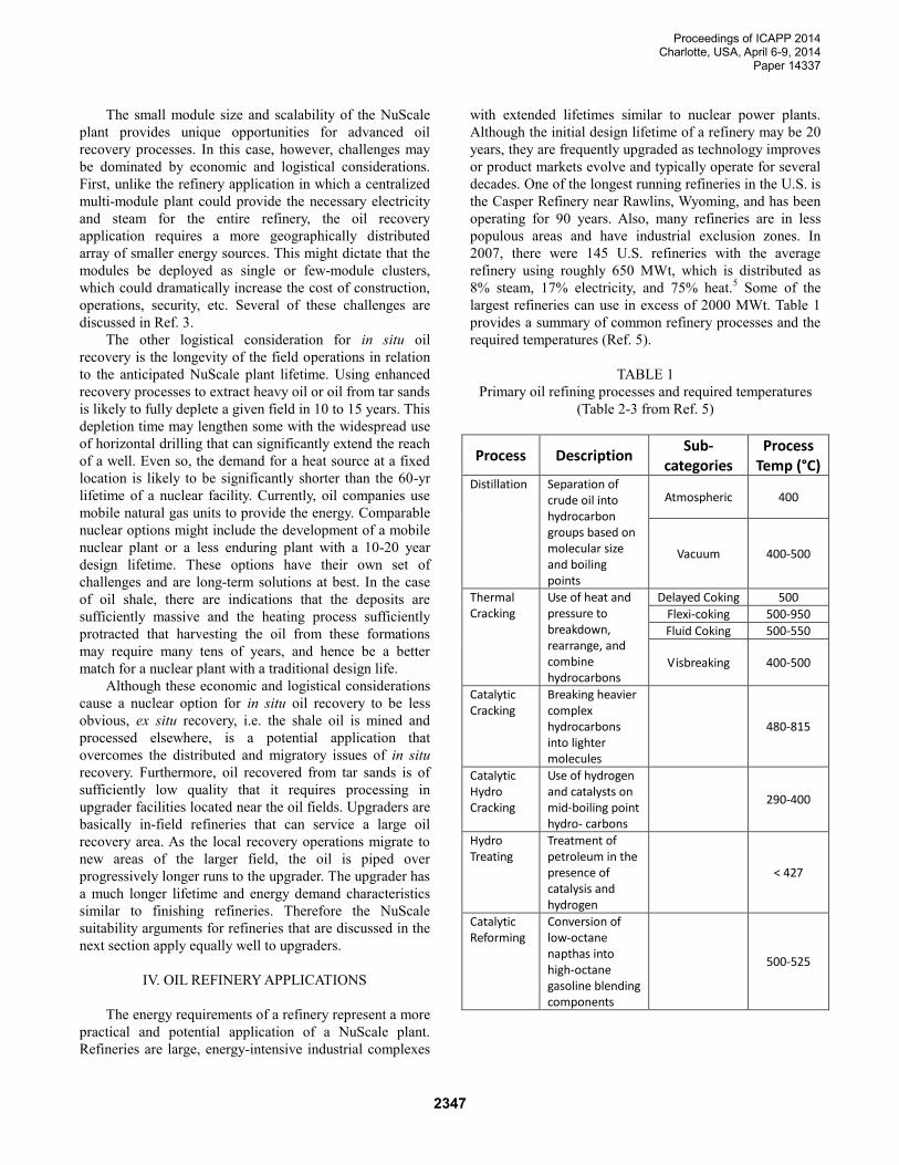
largest refineries can use in excess of 2000 MWt. Table 1
provides a summary of common refinery processes and the
required temperatures (Ref. 5).
TABLE 1
Primary oil refining processes and required temperatures
(Table 2-3 from Ref. 5)
Process Description Sub-
categories Process
Temp (°C) Distillation Separation of
crude oil into hydrocarbon groups based on molecular size and boiling points
Atmospheric 400
Vacuum 400-500
Thermal Cracking
Use of heat and pressure to breakdown, rearrange, and combine hydrocarbons
Delayed Coking 500
Flexi-coking 500-950
Fluid Coking 500-550
Visbreaking 400-500
Catalytic Cracking
Breaking heavier complex hydrocarbons into lighter molecules
480-815
Catalytic Hydro Cracking
Use of hydrogen and catalysts on mid-boiling point hydro- carbons
290-400
Hydro Treating
Treatment of petroleum in the presence of catalysis and hydrogen
< 427
Catalytic Reforming
Conversion of low-octane napthas into high-octane gasoline blending components
500-525
2347
Proceedings of ICAPP 2014 Charlotte, USA, April 6-9, 2014
Paper 14337
The small module size and modular nature of the
NuScale plant is well suited for this application. A multi-
module, multi-output plant can be easily customized to the
needs of a specific refinery while maintaining a highly
standardized nuclear power module design. A single
NuScale power module produces roughly 245,000 kg/hr
steam with an outlet temperature of approximately 300°C.
Since superheated steam has limited use for process
heating, a secondary heat transport medium would be used
such as high pressure water or a specially designed heat
transfer fluid such as DOWTHERM™. An intermediate
heat exchanger transfers heat to the secondary fluid stream
for use in pre-heating refinery process inputs and provides
additional isolation between the reactor and refinery. The
end-use heated fluid characteristics can be adjusted as
needed to match the requirements of a specific process. An
initial estimate is that a single 160 MWt module can
provide for pre-heating of several refinery process input
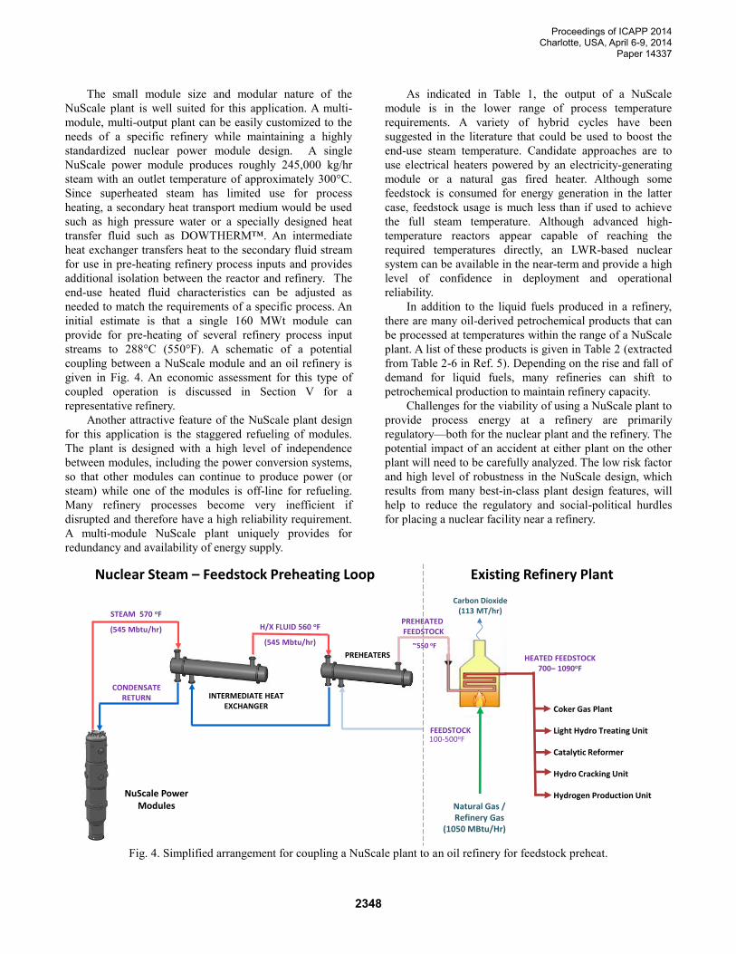
streams to 288°C (550°F). A schematic of a potential
coupling between a NuScale module and an oil refinery is
given in Fig. 4. An economic assessment for this type of
coupled operation is discussed in Section V for a
representative refinery.
Another attractive feature of the NuScale plant design
for this application is the staggered refueling of modules.
The plant is designed with a high level of independence
between modules, including the power conversion systems,
so that other modules can continue to produce power (or
steam) while one of the modules is off-line for refueling.
Many refinery processes become very inefficient if
disrupted and therefore have a high reliability requirement.
A multi-module NuScale plant uniquely provides for
redundancy and availability of energy supply.
As indicated in Table 1, the output of a NuScale
module is in the lower range of process temperature
requirements. A variety of hybrid cycles have been
suggested in the literature that could be used to boost the
end-use steam temperature. Candidate approaches are to
use electrical heaters powered by an electricity-generating
module or a natural gas fired heater. Although some
feedstock is consumed for energy generation in the latter
case, feedstock usage is much less than if used to achieve
the full steam temperature. Although advanced high-
temperature reactors appear capable of reaching the
required temperatures directly, an LWR-based nuclear
system can be available in the near-term and provide a high
level of confidence in deployment and operational
reliability.
In addition to the liquid fuels produced in a refinery,
there are many oil-derived petrochemical products that can
be processed at temperatures within the range of a NuScale
plant. A list of these products is given in Table 2 (extracted
from Table 2-6 in Ref. 5). Depending on the rise and fall of
demand for liquid fuels, many refineries can shift to
petrochemical production to maintain refinery capacity.
Challenges for the viability of using a NuScale plant to
provide process energy at a refinery are primarily
regulatory—both for the nuclear plant and the refinery. The
potential impact of an accident at either plant on the other
plant will need to be carefully analyzed. The low risk factor
and high level of robustness in the NuScale design, which
results from many best-in-class plant design features, will
help to reduce the regulatory and social-political hurdles
for placing a nuclear facility near a refinery.
STEAM 570 oF
(545 Mbtu/hr)
CONDENSATERETURN
NuScale Power Modules
Nuclear Steam – Feedstock Preheating Loop
Natural Gas / Refinery Gas
(1050 MBtu/Hr)
CO2
PREHEATERS
INTERMEDIATE HEAT EXCHANGER
FEEDSTOCK100-500oF
PREHEATED FEEDSTOCK
~550 oF
Carbon Dioxide(113 MT/hr)
H/X FLUID 560 oF
(545 Mbtu/hr)
HEATED FEEDSTOCK700– 1090oF
Coker Gas Plant
Light Hydro Treating Unit
Catalytic Reformer
Hydro Cracking Unit
Hydrogen Production Unit
Existing Refinery Plant
Fig. 4. Simplified arrangement for coupling a NuScale plant to an oil refinery for feedstock preheat.
2348

Proceedings of ICAPP 2014 Charlotte, USA, April 6-9, 2014
Paper 14337
TABLE 2
Process temperatures and annual U.S. production rates of various petrochemicals (Excepts from Table 2-6 of Ref. 5)
Chemical Process Process
Temp (°C) 2002 Production
(billion lb)
Ethylbenzene Friedel-Crafts Alkylation 90-420 13.6
Ethylene Oxide Air Epoxidation 270-290 9.2
Acetic Acid Multiple 50-250 6.7
Cumene Friedel-Crafts Alkylation 175-225 7.3
Cyclohexane Transformation of Benzene 210 3.0
Terephthalic Acid Amoco Process 200 9.1
Vinyl Acetate Vapor-phase Reaction 175-200 2.8
Ethylene Glycol Hydration and Ring Opening 50-195 7.5
Butyraldehde Oxo Process 130-175 3.1
Adipic Acid Air Oxidation 50-160 2.2
Bisphenol A Phenol with Acetone 50 2.3
Ethylene Dichloride 40-50 23.8
Phenol Rearrangement of Cumene Hydroperoxide 30 5.2
Urea 190 18.5
Soda Ash 175
Ammonium Nitrate Vacuum Evaporation 125-140 17.2
Aluminum Sulfate 105-110 2.2
Phosphoric Acid Wet process 75-80 26.8
Nylon 6 and Nylon 6.6 Electrolysis of Brine 280-300 2.6
Polyester 200-290 3.9
V. ECONOMIC ASSESSMENT
To understand the economic viability of supporting a
refinery with a NuScale plant, a typical large-size refinery
was selected capable of processing 250,000 barrels/day of
crude oil to produce diesel fuel, gasoline, petroleum coke
and other petroleum products. Anticipated energy demands
for this scale of refinery are listed in Table 3. Six NuScale
modules are sufficient to provide the required 250 MWe of
electricity for the refinery, as well as the house load for the
NuScale plant.
To determine how many modules are needed to meet
the non-electrical energy demands requires a better
understanding of the detailed process flow characteristics
of the refinery. For example, although steam output from
NuScale modules could be used to replace the refinery fuel
gas (RFG) for some of the fired heaters, the RFG is a by-
product of refinery processes and it is more cost-effective
to consume it internally than to process it further for
external use. Also, the use of natural gas (NG) in a methane
reforming process appears to be the most efficient process
for hydrogen production. However, the technical and
economic suitability of using a NuScale plant to produce
hydrogen through a high-temperature steam electrolysis
method is being evaluated and may result in additional NG
replacement potential. Of the 1,800 MBtu/hr energy
demand listed for NG-supplied fired heaters, it appears that
NuScale-supplied steam can provide approximately 1,660
MBtu/hr. This requires four NuScale modules in addition to
the six modules needed to supply the electrical demand.
Hence, with these assumptions, a 10-module NuScale plant
can meet the selected energy needs indicated in Table 3.
TABLE 3
Primary energy demands for typical refinery producing
250,000 barrels per day
Traditional Energy Source
Energy Demand
(MBtu/hr)
Replaceable by NuScale
Module Natural Gas
For 250 MW of electricity
1,900 1,900
For H2 production 4,100 No
For fired heaters 1,800 1,660
For pilot lights 140 No
Refinery Fuel Gas
For fired heaters 2,000 No
2349

Proceedings of ICAPP 2014 Charlotte, USA, April 6-9, 2014
Paper 14337
Table 4 summarizes the economic assessment of a 10-
module NuScale plant coupled to the refinery, assuming
that the NuScale plant replaces the 250 MW electricity
demand and 1660 MBtu/hr of NG consumption for fired
heaters. The capital cost for the refinery assumes a typical
250 MWe gas-turbine combined cycle plant is used to
produce electricity from the NG. The estimated NuScale
capital cost is for an nth-of-a-kind 10-module plant. The
estimated operating cost for the NuScale plant includes
annual operations and maintenance costs, nuclear waste
fee, and decommissioning fund contributions. The fuel cost
for the NuScale plant is assumed to be fixed at $48.2
million/yr, while the NG cost is treated as a variable. Based
on these assumptions, Fig. 5 shows the potential annual
operating cost savings as a function of the cost of NG with
four different fees levied on CO2 emissions. The higher
operating cost of the NuScale plant is quickly mitigated by
increasing the cost of NG over $5/MBtu or by adding a
surcharge based on CO2 emissions.
TABLE 4
Key economic parameters for 10-module NuScale plant
coupled to 250,000 bbl/d refinery
Fossil Heat
With NuScale
Savings
NG Consumption (MBtu/hr)
7,960 4,366 3,594
CO2 Production (MT/hr)
525 336 189
Capital Cost (million)
$ 290 $ 2,100 ($ 1,810)
Owner’s Cost (million)
$ 70 $ 310 ($ 240)
Annual Operating Cost* (million)
$ 6.8 $ 104.6 ($ 97.8)
Annual Fuel Cost (million)
Variable (subject to
NG unit cost)
$ 48.2 Variable (NG cost
less $48.2)
*Does not include financing fees, taxes or fuel costs
The other economic consideration is the capital cost of
the nuclear facility. Figures 6 and 7 show the potential
payback periods as a function of NG fuel cost for $0/MT
and $40/MT of CO2 emission. Comparing Fig.s 6 and 7, it
is apparent that there is only a modest correlation of
payback period with CO2 emission cost, lowering the 25-yr
payback cost of NG only from $9.5/MBtu to $7.5/MBtu
when imposing a $40/MT CO2 penalty.
This simplified economic assessment is based on
conservative assumptions, including: (1) the module
balance-of-plant equipment for steam/heat-producing
modules have the same cost (capital and O&M) as an
electricity-producing module, i.e. the total plant cost is the
same regardless of individual module product, and (2) no
credit is assumed for utilizing waste heat rejected by the
electricity-producing modules (roughly 100 MWt per
module) to augment the output of the steam-producing
modules.
$-
$50
$100
$150
$200
$250
$300
$350
$400
4.00 6.00 8.00 10.00 12.00 14.00
An
nu
al S
avin
gs (
10
6$
/ y
r)
Cost of Natural Gas ($/MBtu)
CO2 Fee($/MT)
0
20
40
60
Fig. 5. Potential savings in annual operating cost (including
fuel cost) with coupled NuScale-refinery plant.
More rigorous analyses and optimization of the
NuScale plant design for non-electrical applications will
improve the overall economics. In addition, other
externalities could further improve NuScale’s economic
competitiveness, especially regarding the potential impact
of future policies (and resulting costs) regarding air quality
standards and GHG emissions. Although there is no
certainty associated with how much and when the policies
will impact GHG-emitting sources in the U.S, many
countries already enact emission penalties. Also, existing
air quality regulations imposed by the Environmental
Protection Agency severely limit industrial expansion in
non-attainment areas, i.e. locations where air quality is
already below mandated standards. California, which often
leads the country in environmental restrictions, already
restricts the use of high-emission products and is
increasingly concerned over the full life-cycle carbon and
criteria pollutant (SOx, NOx, CO, PM10) footprint of
products. As a consequence of the 2006-enacted Global
Warming Solutions Act (Assembly Bill 32), they will not
allow crude oil from Canada to be imported to CA
refineries because of the “dirty” processing used to acquire
the crude.2
Based on a simple analysis, the NuScale economics
look viable for supporting large refinery applications, even
in the absence of emission penalties. This is particularly
true in countries or regions of the US where low-cost
natural gas is not available. Given regional differences in
energy costs, a more refined study may identify domestic
and international locations with more favorable economics.
2350

Proceedings of ICAPP 2014 Charlotte, USA, April 6-9, 2014
Paper 14337
Also, given the uncertainties in emission penalties, it may
be possible to develop a long-term power (and steam)
purchase agreement structure that is mutually attractive to
NuScale and the oil companies, thus allowing them to
hedge against future emission restrictions and costs.
-$3,000
-$2,000
-$1,000
$0
$1,000
$2,000
$3,000
0 5 10 15 20 25
Ne
t C
ost
($
10
6)
Years
$4/MBtu
$5/Mbtu
$6/MBtu
$7/Mbtu
$8/MBtu
$9/Mbtu
$10/Mbtu
$11/Mbtu
$12/Mbtu
$13/Mbtu
$14/Mbtu
Cost of NG
Fig. 6. Potential capital pay-back period for the case of no
CO2 emmision penalty.
-$3,000
-$2,000
-$1,000
$0
$1,000
$2,000
$3,000
0 5 10 15 20 25
Ne
t C
ost
($
10
6)
Years
$4/MBtu
$5/Mbtu
$6/MBtu
$7/Mbtu
$8/MBtu
$9/Mbtu
$10/Mbtu
$11/Mbtu
$12/Mbtu
$13/Mbtu
$14/Mbtu
Cost of NG
Fig. 7. Potential capital pay-back period for the case of a
$40/MT CO2 emmision penalty.
IV. CONCLUSIONS
A preliminary technical evaluation has been completed
for assessing the potential application of the NuScale SMR
to the substantial energy demands of the oil industry. Both
oil recovery and oil refining applications were considered.
In the case of oil recovery processes, the small unit size,
flexible plant design and enhanced safety features of the
NuScale design make it potentially attractive for distributed
energy delivery, subject to overcoming some identified
logistical challenges. The same design features make the
NuScale design especially well-suited for application to oil
refineries and upgraders, thus reducing the overall GHG
footprint of the refinery and allowing the fossil-based
feedstocks to be preserved for conversion to high-value
fuels.
An economic assessment was performed for the case
of a representative refinery sized to process 250,000
barrels/day of crude oil. The cost differential between using
nuclear-generated electricity and heat relative to the
reference scenario of using natural gas was calculated for a
variety of natural gas prices and potential CO2 tax
penalties. The analysis showed that based only on operating
costs, the 10-module NuScale plant is competitive with the
reference case for natural gas prices as low as $5/MBtu,
even with no CO2 tax. The capital investment for the
NuScale plant can be recovered in 25 years if the natural
gas cost exceeds $9.5/MBtu without a carbon tax, or
$7.5/MBtu with a $40/MT CO2 penalty. While such gas
prices exceed current prices in the U.S., they are well
below prices in many other countries.
REFERENCES
1. C. W. Forsberg, “Sustainability by combining nuclear
fossil, and renewable energy sources,” Progress in
Nuclear Energy, 51, 192-200 (2009)
2. A. Smith, Fluor Corporation, private communication
(2013).
3. D. Curtis and C. W. Forsberg, “Light-Water-Reactor
Arrays for Production of Shale Oil and Variable
Electricity,” ANS Transactions, 108, (2013).
4. Advanced Applications of Water Cooled Nuclear
Power Plants, International Atomic Energy Agency,
TECDCC-1584 (2007).
5. J. Konefal and D. Rackiewicz, “Survey of HTGR
Process Energy Applications,” MPR-3181 (May
2008).
2351