numerical simulations of synthetic jets in...
TRANSCRIPT

INCAS BULLETIN, Volume 6, Special Issue 1/ 2014, pp. 81 – 93 ISSN 2066 – 8201
Numerical simulations of synthetic jets in aerodynamic
applications
Alexandru Catalin MACOVEI*,1, Florin FRUNZULICA2
*Corresponding author
*,1Fokker Engineering Romania
Sos. Pipera 1/VII Nord City Tower, Voluntari, Ilfov, Romania
[email protected]; 2“POLITEHNICA” University of Bucharest, Faculty of Aerospace Engineering
Polizu 1-6, RO-011061, Bucharest, Romania
DOI: 10.13111/2066-8201.2014.6.S1.9
Abstract: This paper presents numerical simulations of synthetic jets in aerodynamic applications.
We’ve analyzed the formation of isolated synthetic jets, the influence of nozzle geometry and the
interaction of synthetic jets with a uniform flow on a flat plate. Also we’ve studied the influence of the
active control in interaction with a stalled airfoil and the controllability of dynamic stall phenomenon.
The results are obtained using a dedicated CFD solver. Appropriate comparisons are made with
results from scientific literature; as well the numerical results are compared with a set of
experimental images.
Key Words: synthetic jet, actuator, flow control, active control, dynamic stall, boundary layer
I. INTRODUCTION
A relatively new device for controlling the flow, produced and tested in the laboratory, is
known as "synthetic jet actuator". Synthetic jets are produced by a sound source which is at
the base of a cavity communicating with the surface exposed to the flow through the circular
orifice, as seen in Figure 1.
Figure 1. The conceptual scheme of synthetic jet
actuator [3] Figure 2. Zoning of acoustic jets [3]

Alexandru Catalin MACOVEI, Florin FRUNZULICA 82
INCAS BULLETIN, Volume 6, Special Issue 1/ 2014
The actuator is composed of a rigid-walled chamber, an inlet in the upper part exposed
to the exterior flow and an elastic membrane which is opposite the orifice. In the phase in
which the membrane moves down ward, the outside fluid is drawn into the cavity through
the opening. When the membrane moves up, the fluid is discharged through the opening
back to the outside flow. If the jet has sufficient energy a vortex ring is generated.
When the cycle is repeated periodically, a vortices column is generated. Sintered
synthetic jet adds momentum to the fluid from the outside flow, this happens without added
flux mass. Therefore synthetic jets are preferred at the expense of conventional jets.
At a high level of excitation of the elastic membrane, represented by the maximum
amplitude of the membrane displacement, it is observed the emanation of a regular fluid jet.
Because there is no additional contribution of mass, the stream lines should form a closed
circulation as shown in Figure 1. This phenomenon of acoustic jet stream through an orifice
which is based on a highly excited acoustic diaphragm is well known for many years. Figure
2, [3], shows the four regimes of circulation and turbulence around an acoustically excited
orifice plate in terms of acoustic neck velocity (amplitude) versus frequency. The dotted line
corresponds to the area where the particle displacement amplitude is equal to the length of
the aperture hole.
At a low excitation level in region 1 and region 2, under the dotted line, a small amount
of fluid particles are moving into and out of the cavity without interfering with the fluid
outside the cavity. A small amount of acoustic energy is lost to the outside by the
phenomenon of acoustic radiation.
Near and above the dotted line, in region 3, significant turbulence are generated near the
neck of the orifice, however, a part of the acoustic energy is transferred to the fluid particles.
At high excitation levels, in region 4, the movement of the fluid particles extends
beyond the opening providing sufficient time for the particles to form a vortex ring, with a
circular aperture. This vortex is separated from the region of the orifice and cause a
disturbance powered by the movements caused by convection vortex, thus synthetic jets are
formed. All simulations done in this study are made so that the combination of amplitude
and frequency should be in region 4.
In the last two decades the synthetic jets and the flow mechanism of its interaction with
a cross-flow have been intensively investigated numerically and experimentally.
The advantage of these jets is that they can transfer linear momentum to the main flow
without mass injection.
Synthetic jets cover a large range of time and length scales and thus can be attractive for
many applications: the flow control of the boundary layer separation, command systems with
jets, thrust vectoring, flow control on wind turbines, forced air cooling.
The present work is organized around the following problems: the generation of the
synthetic jet, main parameters that characterize synthetic jet performances, the interaction of
the synthetic jet with laminar boundary layer, and the effect of synthetic jet on the dynamic
stall phenomenon. All investigations are performed numerically using ANSYS FLUENT.
II. GENERATION OF SYNTHETIC JETS
This study proposes the development of sets of numerical simulations at different
frequencies and amplitudes of oscillation of the elastic membrane. The actuator has a fixed
geometry with the following dimensions:
𝐷0 = 5 𝑚𝑚 ℎ = 5 𝑚𝑚 𝐷𝑐 = 45 𝑚𝑚 𝐻 = 10 𝑚𝑚

83 Numerical simulations of synthetic jets in aerodynamic applications
INCAS BULLETIN, Volume 6, Special Issue 1/ 2014
Figure 3 Synthetic jet actuator nozzle Figure 4. Computational domain and mesh
Any numerical results depend on the grid and the computational domain. For validation
of a numerical simulation it is necessarily to prove that results are independent on the grid. In
this work the numerical simulations were performed using two different grids. The
differences between the results obtained with a grid containing 54000 and the results
obtained with a grid containing 216000 elements are negligible.
Consequently, the simulations will be conducted using the grid with fewer elements in
order to increase the calculation speed and to minimize the space required to store the
results.
The numerical simulations are performed in ANSYS Fluent 13. An incompressible
pressure solver based on a second order SIMPLE algorithm is utilized. The simulations are
non-stationary and the problem is axially symmetric.
The laminar flow model is used; the working fluid is considered to be air having
standard properties. To simulate the movement of the membrane the dynamic grid option is
used. The motion law is implemented using a UDF.
The time step varies with the membrane oscillation frequency ∆t=1/f
200 where f is the
frequency. Figure 5 and Figure 6 present the results of numerical simulations. The sequences
reveal the vorticity at different moments of time.
The results in Figure 5 are obtained for a frequency f= 50Hz and an amplitude Δ= 0.4
mm. It is noted that the synthetic jet is weak for this combination of frequency and
amplitude.
Instead, the results presented in Figure 6 are obtained for f = 400 Hz and an amplitude
Δ= 0.8 mm.
The amplitude of the velocity is much higher than the speed of the former case, which
leads to the complete development of synthetic jet, thus demonstrating the validity of the
graph shown in Figure 2.

Alexandru Catalin MACOVEI, Florin FRUNZULICA 84
INCAS BULLETIN, Volume 6, Special Issue 1/ 2014
Figure 5. Synthetic jet vorticity contours for 50
Hz frequency
Figure 6. Synthetic jet vorticity contours for 400 Hz
frequency
The magnitude of speed is higher than the speed of the previous case, which leads to the
complete development of the synthetic jet, thus demonstrating the validity of the graph
shown in Figure 2.
III. PARAMETERS WHICH DESCRIBE THE PERFORMANCE OF THE
CIRCULAR SYNTHETIC JETS
The synthetic jets are characterized by the formation of vortex rings. The power of a vortex
ring, in terms of the intensity of circulation, determines its impact on the boundary layer.
In order to ensure that the vortex rings have the strength to affect the boundary layer, it
is necessary to know the parameters that influence the formation and propagation of the se
vortex rings.
In terms of concept, it is of interest to be highlighted how the actuator geometry can be
optimized to enhance the power of the vortex rings.
The study is based on the consideration that the membrane is embedded around the
circumference.
Simulations are performed for different fixed values of amplitude and frequency.
According to the theory of plates [13], the deformation of the membrane can be described by
the following equation:
𝛿(𝑟, 𝑡) =∆
2∙ [1 − (
𝑟2
𝑟𝑐2) + (
2 ∙ 𝑟2
𝑟𝑐2 ) ∙ ln (
𝑟
𝑟𝑐)] ∙ sin(2 ∙ 𝜋 ∙ 𝑓 ∙ 𝑡) (1)

85 Numerical simulations of synthetic jets in aerodynamic applications
INCAS BULLETIN, Volume 6, Special Issue 1/ 2014
where:
- 𝛿 is the relative deflection of the diaphragm towards the neutral position;
- 𝑟 is the radial distance from the center of the diaphragm, 𝑟ϵ(0, 𝑟𝑐]; - 𝑟𝑐 is the diaphragm radius.
Figure 7. Dependence of displacement 𝛅 by r and t for ∆= 𝟎. 𝟖𝐦𝐦 f=50 Hz
Differentiating equation (1) according to time is obtained the speed of oscillation of the
membrane
𝜕𝛿(𝑟, 𝑡)
𝜕𝑡= 𝑢(𝑟, 𝑡) = 𝜋 ∙ 𝑓 ∙ ∆ ∙ [1 − (
𝑟2
𝑟𝑐2) + (
2 ∙ 𝑟2
𝑟𝑐2 ) ∙ ln (
𝑟
𝑟𝑐)] ∙ cos(2 ∙ 𝜋 ∙ 𝑓 ∙ 𝑡) (2)
In the case of compressible flows, applying the law of conservation of mass, the
instantaneous flux of fluid passing through the orifice is given by the equation:
𝑄0̇(𝑡) = 𝜌 ∙ �̃�0(𝑡) ∙ 𝐴
= 𝜌 ∙ ∫ 𝑢(𝑟, 𝑡) ∙ 2 ∙ 𝜋 ∙ 𝑟 ∙ 𝑑𝑟 =𝜋2
16
𝑟𝑐
0
∙ 𝜌 ∙ ∆ ∙ 𝑓 ∙ 𝐷𝑐2 ∙ 𝑐𝑜𝑠(2 ∙ 𝜋 ∙ 𝑓 ∙ 𝑡) (3)
where A is the orifice section.
Figure 8. Dependence of fluid flux with time ∆=0.8 mm f=50
Figure 9. Instantaneous velocity∆= 0.8 mm f=50 Hz
The fluid leaving the orifice with velocity:
�̃�0(𝑡) =𝑄0̇(𝑡)
𝜌 ∙ 𝐴=
𝜋
4∙ ∆ ∙ 𝑓 ∙ (
𝐷𝑐
𝐷0)
2
∙ cos(2 ∙ 𝜋 ∙ 𝑓 ∙ 𝑡) (4)

Alexandru Catalin MACOVEI, Florin FRUNZULICA 86
INCAS BULLETIN, Volume 6, Special Issue 1/ 2014
The velocity �̃�0(𝑡) is the fundamental criterion for estimating the performance of the jet,
when no velocity profile information is available. Because �̃�0(𝑡) is independent of the
orifice and cavity depth, changing of these two dimensions is irrelevant and is not taken into
account in this model. The maximum velocity, �̃�𝑚𝑎𝑥, and the mean velocity over a complete
cycle, �̅�0, can be determined from eq. 4:
�̃�𝑚𝑎𝑥 =𝜋
4∙ ∆ ∙ 𝑓 ∙ (
𝐷𝑐
𝐷0)
2
(5)
�̅�0 =1
𝑇∙ ∫ �̃�0(𝑡)𝑑𝑡 =
1
4
𝑇2⁄
0
∙ ∆ ∙ 𝑓 ∙ (𝐷𝑐
𝐷0)
2
(6)
where: T is the period of oscillation of the membrane.
The total fluid flux, 𝑄0 and the mean fluid flux, �̅̇�0 over a complete cycle are:
𝑄0 = ∫ 𝑄0̇(𝑡)𝑑𝑡 =𝜋
16
𝑇2⁄
0
∙ 𝜌 ∙ ∆ ∙ 𝐷𝑐2 (7)
�̅̇�0 =𝑄0
𝑇=
𝜋
16∙ 𝜌 ∙ ∆ ∙ 𝑓 ∙ 𝐷𝑐
2 (8)
If �̃�0(𝑡) is used for replacing the velocity profile 𝑢0(𝑟, 𝑡), the instantaneous momentum
of the fluid flux could be approximated with the next relation:
�̇�0(𝑡) = 𝜌 ∙ ∫ 𝑢02(𝑟, 𝑡) ∙ 2 ∙ 𝜋 ∙ 𝑟 ∙ 𝑑𝑟 ≅ 𝜌 ∙ �̃�0
2𝑟𝑐
0
(𝑡) ∙ 𝐴
=𝜋3
64∙ 𝜌 ∙ ∆2 ∙ 𝑓2 ∙ 𝐷0
2 ∙ (𝐷𝑐
𝐷0)
4
∙ 𝑐𝑜𝑠2(2 ∙ 𝜋 ∙ 𝑓 ∙ 𝑡)
(9)
Figure 10. Instantaneous momentum ∆= 0.8 mm
f=50 Hz Figure 11. Vortex circulation dependence function of
∆ and f
Therefore, the total momentum of the flow of fluid passing through the orifice during
one complete cycle 𝐼0 can be approximated by the following relation:
𝐼0 = ∫ �̇�0(𝑡)𝑑𝑡 ≅𝜋3
256
𝑇2⁄
0
∙ 𝜌 ∙ ∆2 ∙ 𝑓 ∙ 𝐷02 ∙ (
𝐷𝑐
𝐷0
)4
(10)
The next relation is used for calculation the mean momentum:
�̅̇�0 =𝐼0
𝑇≅ (
𝜋3
256) ∙ 𝜌 ∙ ∆2 ∙ 𝑓2 ∙ 𝐷0
2 ∙ (𝐷𝑐
𝐷0
)4
(11)
87 Numerical simulations of synthetic jets in aerodynamic applications
INCAS BULLETIN, Volume 6, Special Issue 1/ 2014
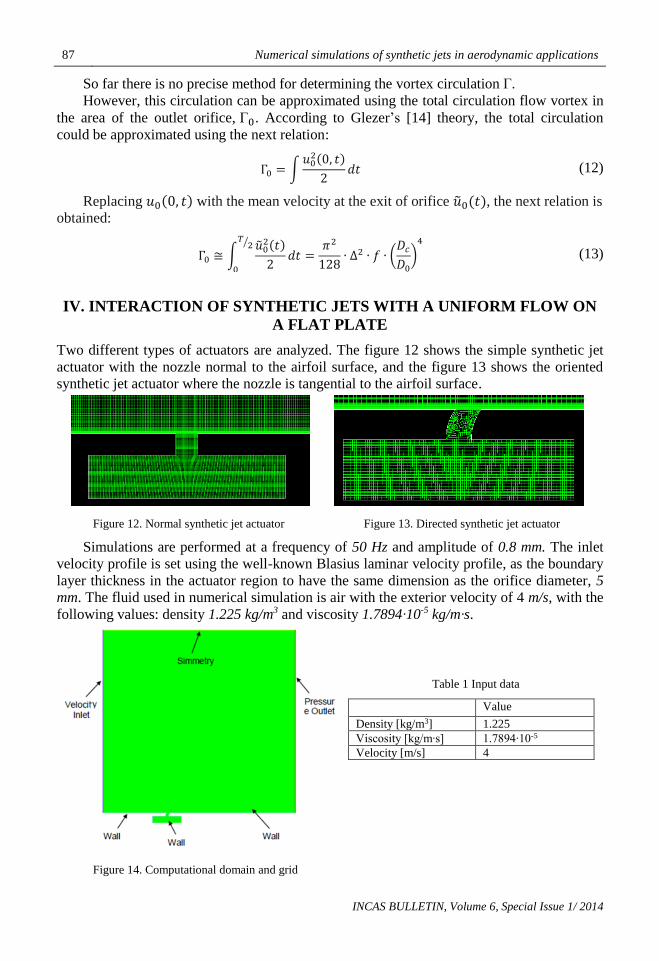
So far there is no precise method for determining the vortex circulation Γ.
However, this circulation can be approximated using the total circulation flow vortex in
the area of the outlet orifice, Γ0. According to Glezer’s [14] theory, the total circulation
could be approximated using the next relation:
Γ0 = ∫𝑢0
2(0, 𝑡)
2𝑑𝑡 (12)
Replacing 𝑢0(0, 𝑡) with the mean velocity at the exit of orifice �̃�0(𝑡), the next relation is
obtained:
Γ0 ≅ ∫�̃�0
2(𝑡)
2
𝑇2⁄
0
𝑑𝑡 =𝜋2
128∙ ∆2 ∙ 𝑓 ∙ (
𝐷𝑐
𝐷0
)4
(13)
IV. INTERACTION OF SYNTHETIC JETS WITH A UNIFORM FLOW ON
A FLAT PLATE
Two different types of actuators are analyzed. The figure 12 shows the simple synthetic jet
actuator with the nozzle normal to the airfoil surface, and the figure 13 shows the oriented
synthetic jet actuator where the nozzle is tangential to the airfoil surface.
Figure 12. Normal synthetic jet actuator Figure 13. Directed synthetic jet actuator
Simulations are performed at a frequency of 50 Hz and amplitude of 0.8 mm. The inlet
velocity profile is set using the well-known Blasius laminar velocity profile, as the boundary
layer thickness in the actuator region to have the same dimension as the orifice diameter, 5
mm. The fluid used in numerical simulation is air with the exterior velocity of 4 m/s, with the
following values: density 1.225 kg/m3 and viscosity 1.7894∙10-5 kg/m∙s.
Table 1 Input data
Value
Density [kg/m3] 1.225 Viscosity [kg/m∙s] 1.7894∙10-5 Velocity [m/s] 4
Figure 14. Computational domain and grid

Alexandru Catalin MACOVEI, Florin FRUNZULICA 88
INCAS BULLETIN, Volume 6, Special Issue 1/ 2014
Figure 14 shows the computational domain and the boundary condition used for the
numerical simulation of this section.
There could be observed that the membrane of the actuator is represented as a wall. In
order to maintain the laminar flow over the all plate, the Reynolds number must remain
below the critical value 𝑅𝑒𝑐𝑟 = 500000.
Figure 15. Velocity profile at different locations on the plate
The coordinates for each location are calculated considering the axis system with the
origin at the center of the orifice: XA = − 0.015 m; XB = 0.015 m; XC = 0.030 m; XD =0.045 m; XE = 0.090 m (figure 15).
A graphic comparison between the theoretical velocity profile (the Blasius velocity
profile), the velocity profile perturbed by a normal synthetic jet actuator, and the velocity
profile perturbed by an oriented synthetic jet actuator, is shown in the figure 16.
Location T=0.008s T=0.038s
A
B
C

89 Numerical simulations of synthetic jets in aerodynamic applications
INCAS BULLETIN, Volume 6, Special Issue 1/ 2014
D
E
Figure 16. Velocity profile at different sections using two types of actuators
V. CONTROLLABILITY OF DYNAMIC STALL USING SYNTHETIC JETS
The phenomenon of dynamic stall is encountered in aeronautics at rotor blades. The purpose
of this study is to evaluate the effect of using synthetic jet to delay the flow separation and
therefore the reduction of hysteresis loop of the aerodynamic forces.
We investigated numerically the case of the NACA0012 airfoil with a chord length c
=15 cm, which executes a sinusoidal pitching motion, 𝛼(𝑡) = 10° + 15° ∙ sin(18.67 𝑡), around the point located at ¼ c from the leading edge (corresponding to a reduced frequency
𝑘 =𝜔∙𝑐
2∙𝑉∞= 0.1.
The airfoil is placed in a free uniform flow with velocity V =14 m/ s and turbulence
intensity of about 1%.
The Reynolds number is 𝑅𝑒 = 1.35 ∙ 105.
For the present study, unsteady Reynolds averaged Navier-Stokes (RANS) model is the
suitable approach to perform the dynamic stall flow simulations with an acceptable
computational cost and, at least, reasonable accuracy.
The turbulence model used in Fluent is K-𝜔-SST.
The computational domain is composed by an inner circular domain which executes a
rigid pitching motion around its center with angular velocity �̇�(𝑡) = 15° ∙ 18.67 ∙
cos(18.67 𝑡) ∙𝜋
180 and a fixed exterior circular domain with radius 26 c. The hybrid grid has
760000 nodes; about 1000 nodes are placed on the airfoil surface and clustered close to
leading and trailing edges.
The height of the first row of cells bounding the airfoil is set to 10−5 ∙ 𝑐 which ensures
𝑦+ ≤ 1 for a properly resolved of viscous laminar sub layer.
Alexandru Catalin MACOVEI, Florin FRUNZULICA 90
INCAS BULLETIN, Volume 6, Special Issue 1/ 2014
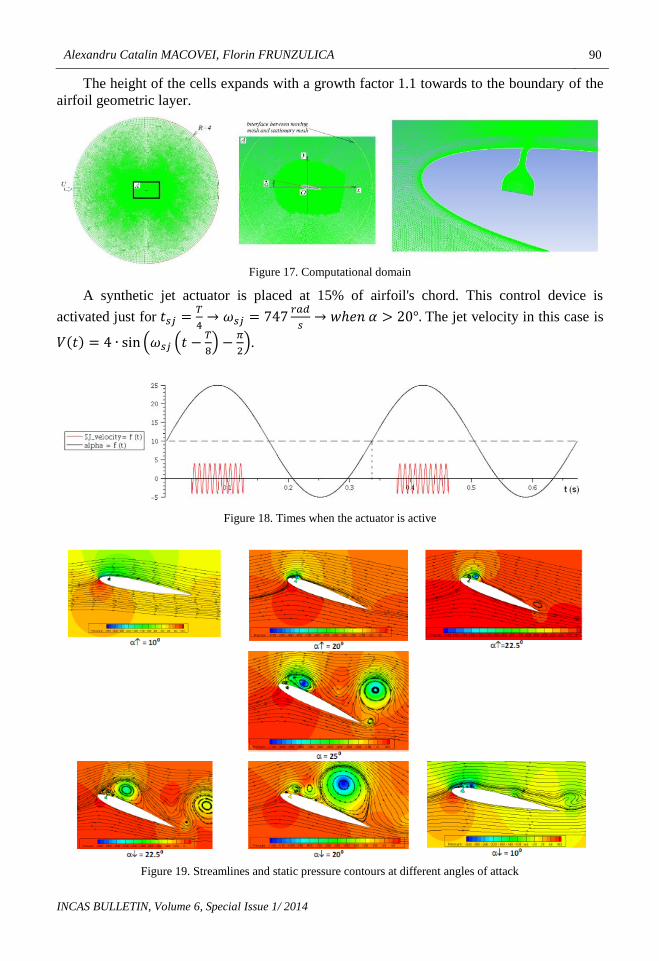
The height of the cells expands with a growth factor 1.1 towards to the boundary of the
airfoil geometric layer.
Figure 17. Computational domain
A synthetic jet actuator is placed at 15% of airfoil's chord. This control device is
activated just for 𝑡𝑠𝑗 =𝑇
4→ 𝜔𝑠𝑗 = 747
𝑟𝑎𝑑
𝑠→ 𝑤ℎ𝑒𝑛 𝛼 > 20°. The jet velocity in this case is
𝑉(𝑡) = 4 ∙ sin (𝜔𝑠𝑗 (𝑡 −𝑇
8) −
𝜋
2).
Figure 18. Times when the actuator is active
Figure 19. Streamlines and static pressure contours at different angles of attack

91 Numerical simulations of synthetic jets in aerodynamic applications
INCAS BULLETIN, Volume 6, Special Issue 1/ 2014
In Figure 19 we present streamlines over pressure contours (gauge pressure) at a few
time steps in airfoil pitching motion with synthetic jet control.
We notice that the synthetic jet reduces the hysteresis of aerodynamic coefficients as
seen in Figure 20(a).
The high impulse of the jet produces a quick separation of vortex generated at the
leading edge and the flow becomes unstable on the upper surface.
More numerical simulations are necessary to identify an optimal position of the control
device and the proper set of frequencies and amplitude for the membrane motion.
(a) (b)
Figure 20. Numerical simulations of dynamic stall phenomenon
The Figure 20(a) shows a comparison between the hysteresis lift coefficient using
turbulence models K-𝜔-SST, Transitional SST and experimental data. The Figure 20(b)
presents a comparison between the lift coefficient with synthetic jet and the experimental
data without synthetic jets.
VI. CONCLUSIONS
In this paper we analyze the numerical and experimental behavior of the synthetic jets. Using
ANSYS-Fluent a set of numerical simulations for eight different frequencies (50-400 Hz)
and a range of five amplitudes (0.4-1.2 mm) was performed.
Using the simulations performed on a flat plate it was found that the directed synthetic
jet actuator provides better results than the simple synthetic jet actuator.
From the scientific literature and the investigations conducted on synthetic jets there are
found a wide range of benefits as for instance the boundary layer velocity profile thickness
increase, the drag coefficient decrease, and the lift coefficient increase.
At the same time there are a number of disadvantages related to the control system
maintenance, and many manufacturing issues in the case of the oriented synthetic jets.
There are a number of practical applications where the synthetic jets proved to be
effective: the missiles micro jets control systems, and cooling systems with micro jets.
This paper provides a starting point for the following research projects and in the future
we intend to continue the study of the active control of flow.
-1
-0.5
0
0.5
1
1.5
2
2.5
3
-10 -5 0 5 10 15 20 25 30
alpha (deg)
Cl
Trans. SST
Exp.
k-w,SST

Alexandru Catalin MACOVEI, Florin FRUNZULICA 92
INCAS BULLETIN, Volume 6, Special Issue 1/ 2014
REFERENCES
[1] L. D. Kral (deceased), ACTIVE FLOW CONTROL TECHNOLOGY, ASME Fluids Engineering Division
Technical Brief, Washington University St. Louis, Missouri, 2008.
[2] J. E. Green, Laminar Flow Control – Back to the Future?, Aircraft Research Association Ltd., Bedford UK,
MK41 7PF 38th Fluid Dynamics Conference and Exhibit BR 23 - 26 June 2008, Seattle, Washington.
[3] S. Zhong, M. Jabbal, H. Tang, L. Garcillan, F. Guo, N. Wood, C. Warsop, Towards the Design of Synthetic-
jet Actuators for Full-scale Flight Conditions Part 1: The Fluid Mechanics of Synthetic-jet Actuators,
Received: 16 April 2006 / Accepted: 23 November 2006 / Published online: 2 March 2007 # Springer
Science + Business Media B.V. 2007.
[4] R. Rathnasingham and K. S. Breuer, Characteristics of Resonant Actuators for Flow Control, AIAA Paper
96-0311, Jan. 1996.
[5] J. T.Lachowicz, C. S. Yao and R. W. Wlezien, Scaling of an OscillatoryFlow-Control Actuator, AIAA Paper
98-0330, Jan. 1998.
[6] M. O. Muller, L. P. Bernal, P. K. Miska, P. D. Washabaugh, T. A. Chou, B. A. Parviz, C. Zhang and K.
Najafi, Flow Structure and Performance of Axisymmetric Synthetic Jets, AIAA Paper 2001-1008, Jan.
2001.
[7] A. Crook, The Control of Turbulent Flows Using Synthetic Jets, Ph.D. Dissertation, School of Engineering,
Univ. of Manchester, Manchester, England, U.K., Jan. 2002.
[8] D. P. Rizzetta, M. R. Visbal and M. J. Stanek, Numerical Investigation of Synthetic-Jet Flowfields, AIAA
Journal, Vol. 37, No. 8, pp. 919–927, 1999.
[9] C. Y. Lee and D. B. Goldstein, Two-Dimensional Synthetic Jet Simulation, AIAA Journal, Vol. 40, No. 3, pp.
510–516, 2002.
[10] Y. Utturkar, R. Mittal, P. Rampunggoon and L. Cattafesta, Sensitivity of Synthetic Jets to the Design of the
Jet Cavity, AIAA Paper 2002-0124, Jan. 2002.
[11] J. M. Shuster and D. R. Smith, A Study of the Formation and Scaling of a Synthetic Jet, AIAA Paper 2004-
0090, Jan. 2004.
[12] H. Tang and S. Zhong, 2D Numerical Study of Circular Synthetic Jets in Quiescent Flows, Aeronautical
Journal, Vol. 109, No. 1092, pp. 89–97, 2005.
[13] S. Timoshenko and S. Woinowsky-Krieger, Theory of Plates and Shells, 2nd ed., McGraw–Hill, London, pp.
67–69, 1959.
[14] A. Glezer, The Formation of Vortex Rings, Physics of Fluids, Vol. 31, No. 12, pp. 3532–3542, 1988.
[15] N.Didden, On the Formation of Vortex Rings: Rolling-Up and Production of Circulation, Zeitschrift f¨ur
Angewandte Mathematik und Physik, Vol. 30, pp. 101–106, Jan. 1979.
[16] S. Zhong, H. Tang, Incompressible Flow Model of Synthetic Jet Actuators, AIAA Journal (Impact Factor:
1.08). 01/2006; 44(4): 908-912, DOI:10.2514/1.15633, University of Manchester
[17] D. C. McCormick, Boundary layer separation control with directed synthetic jets, AIAA 2000-0519, United
Technologies Research Center, 1999.
[18] R. Duvigneau, A. Hay & M. Visonneau, Optimal location of a synthetic jet on an airfoil for stall control,
Journal of Fluids Engineering, Vol. 129, No 7, pp. 825-833, July 2007.
[19] F. Frunzulica, A. Dumitrache, H. Dumitrescu and O. Preotu, Flow control of separating boundary layer on
the Coanda surface, POLITEHNICA” University of Bucharest, Faculty of Aerospace Engineering.
[20] *** ANSYS FLUENT 12.0 User's Guide
[21] F.Frunzulica, A. Dumitrache, O. Preotu, H. Dumitrescu, Active and passive control methods on the
aerodynamic surfaces,The 35th Annual Congress of the American Romanian Academy of Arts and
Sciences (ARA35), July 6-10, 2011 , Timisoara – ROMANIA (Proceedings), (The 35th Annual Congress
of the American Romanian Academy of Arts and Sciences - Proceedings, pp. 171-174, ISBN 978-2-553-
01596-0).
[22] F. Frunzulica, A. Dumitrache, H. Dumitrescu and O. Preotu, Active control of separating boundary layer on
the Coanda surface, 4th European Conference for Aerospace Sciences, EUCASS 2011, Sankt-Petersburg,
Russia, July 4, 2011 – July 8, 2011 (Technical reports. Conference Proceedings), (Technical report
EUCASS 612-04-2011).
[23] F. Frunzulica, H. Dumitrescu, R. Mahu and O. Preotu, Active and Passive Lift Force Augmentation
Techniques on Wind Turbines, 9th International Conference of Numerical Analysis and Applied
Mathematics – ICNAAM 2011, Halkidiki, Greece, 19-2 September 2011 (American Institute of Physics
Proceedings ISBN 978-0-7354-0954-5), AIP Conf. Proc. 1389, pp. 1507-1510; doi:10.1063/1.3637911 (4
pages), NUMERICAL ANALYSIS AND APPLIED MATHEMATICS ICNAAM 2011, Date: 19–25
September 2011.

93 Numerical simulations of synthetic jets in aerodynamic applications
INCAS BULLETIN, Volume 6, Special Issue 1/ 2014
[24] M. Amitay, A. M. Honohan, M. Trautman and A. Glezer, Modification of the aerodynamic characteristics of
bluff bodies using fluidic actuators, 28th AIAA Fluid Dyn. Conf. 97-2004, Snowmass, Colo., 1997.
[25] A. Glezer and M. Amitay, Synthetic Jets, Rev. Fluid Mech. 34:503–29., 2002.
[26] B. L. Smith, A. Glezer, Vectoring of a high aspect ratio air jet using zero-net-mass-flux control jet, Bull. Am.
Phys. Soc.39: 1894, 1994.
[27] F. J. Chen, G. B. Beeler, R. G. Bryant, R. L. Fox, Development of synthetic jet actuators for active flow
control at NASA Langley, AIAA Fluids Meet. 2000-2405, Denver, Colo., 2000.
[28] R. Mahalingam, N. Rumigny, A. Glezer, Thermal management using synthetic jet ejectors, Components and
Packaging Technologies, IEEE Transactions, Volume 27, 3: 439-444., 2004.