numerical simulations of multi-layer-liquid sloshing by
TRANSCRIPT

938
Numerical simulations of multi-layer-liquid sloshing by multiphase MPS method * Xiao Wen, Wei-wen Zhao, De-cheng Wan Computational Marine Hydrodynamics Lab (CMHL), School of Naval Architecture, Ocean and Civil Engineering, Shanghai Jiao Tong University, Shanghai 200240, China
(Received August 29, 2021, Revised September 3, 2021, Accepted September 4, 2021, Published online November 8, 2021) ©China Ship Scientific Research Center 2021 Abstract: In this paper, a multiphase moving particle semi-implicit (MPS) method is developed by introduction of various multiphase models into the original MPS method for single-phase flows, and is then applied to the numerical simulations of two-layer-liquid and three-layer-liquid sloshing in a 2-D rectangular tank under different external excitations. To validate the accuracy of the present multiphase MPS method, the qualitative and quantitative results, including wave profiles, interface elevations and impact pressures, are compared with experimental data and other numerical results, which show a good agreement. In particular, the evolutions of free surface and phase interfaces are compared and an obvious discrepancy is found, indicating that the phase interfaces may suffer from complex deformations while the free surface keeps relatively quiet. Moreover, the different modes of phase interface are observed under different excitation frequencies. Then, the violent sloshing of a three-layer-liquid system is simulated and the phenomenon of internal wave breaking is well captured, which mainly benefitted from the Lagrangian basis of MPS method and its advantage in multiphase flows with complex interfaces. Finally, the three-layer-liquid sloshing with a vertical baffle are simulated to investigate the suppressing effect of baffle on multi-layer-liquid sloshing.
Key words: Moving particle semi-implicit (MPS), multiphase flows, multi-layer-liquid, liquid sloshing
Introduction Liquid sloshing phenomena can be characterized
as strong and nonlinear motion of liquids in closed tanks motivated by external excitations[1-4]. In particu- lar, for tanks installed on marine structures, large dynamic loads are generated by impacting of sloshing flows, which has a negative influence on the strength of liquid tanks and the stability of marine structures[5-7]. Therefore, the liquid sloshing has always been a research focus in marine engineering.
In the last decades, the CFD method has been proven to be effective to compute sloshing flows and the tools can be generally divided into the mesh-based methods[8-10] and mesh-free methods[11-13]. However, the mesh-based methods need an extra algorithm to capture interfaces, such as VOF or level set, which
* Projects supported by the National Natural Science Foundation of China (Grant Nos. 52131102, 51879159), the National Key Research and Development Program of China (Grant Nos. 2019YFC0312400, 2019YFB1704200). Biography: Xiao Wen (1990-), Male, Ph. D., E-mail: [email protected] Corresponding author: De-cheng Wan, E-mail: [email protected]
may bring additional errors when applied to sloshing flows with complex free surfaces. In contrast, the computational domain in mesh-free methods[14-17] is discretized by a set of particles and the motion of particles follows the governing equations in Lagrangian description. According to particle distri- bution, the shape of free surface can be obtained without additional tracking techniques, hence the mesh-free methods are more suitable for violent sloshing flows. For example, as a popular kind of mesh-free method, the moving particle semi-implicit (MPS) method[16-17] has been widely used in the study of sloshing flows[18-23] since it was proposed.
However, until now, the mesh-free methods have rarely been applied to multi-layer-liquid sloshing, which occurs if the tank is filled with several layer of immiscible liquids, such as in the oil-water separators on FPSOs. Compared with single-phase sloshing, the multi-layer-liquid sloshing is more complicated because the natural frequency varies drastically between different layers. Even under the same external excitation, fluids inside different layers may exhibit completely different sloshing characteristics and the deformations of both free surface and phase interfaces are likely to be induced. So far, the studies of multi-layer-liquid sloshing are mainly carried out
Available online at https://link.springer.com/journal/42241
http://www.jhydrodynamics.com Journal of Hydrodynamics, 2021, 33(5): 938-949
https://doi.org/10.1007/s42241-021-0083-z
939
by experimental methods, theoretical analysis and mesh-based numerical methods. For instance, La Rocca et al.[24] performed both theoretical and experimental studies on two-layer-liquid sloshing, and a good agreement is obtained. Sciortino et al.[25] defined a Hamiltonian mathematical model to describe the two-layer-fluid sloshing in a tank with an arbitrary shape and an arbitrary rigid motion. The obtained results are validated by comparison with a laboratory experiment. Molin et al.[26] reported an experiment on the three-layer-liquid sloshing and then compared the experimental data with simulations by potential theory and VOF method, respectively. A good agreement is achieved between experimental and numerical RAOs of the motions of phase interfaces.
The aim of this paper is to carry out the numerical simulations of multi-layer-liquid sloshing by use of multiphase MPS method. Some pioneering works in this field are performed by Kim et al.[27], who firstly simulated three-layer-liquid sloshing through a new multiphase MPS method, which is then coupled with ship motion data in time domain to consider interactions between the sloshing flow and ship motion[28]. Their MPS results show a good agreement with experimental data, but in some more violent cases, the captured interfaces are not smooth enough due to unphysical particle penetrations. As the development of MPS method in recent years, some multiphase methods[29-31] with improved accuracy and stability are proposed and show great advantages in capturing complex phase interfaces in violent multiphase flows, hence we think that it is necessary to further extend the applications of MPS method in multi-layer-liquid sloshing.
In the following sections, a multiphase MPS method would be firstly developed. Then, the simula- tions of two-layer-liquid and three-layer-liquid sloshing in a 2-D rectangular tank are respectively carried out under different external excitations. For verification purposes, the MPS results of wave profiles, interface elevations and impact pressures are compared with experimental data and other numerical results in the open literature. Subsequently, the violent three-layer-liquid sloshing is simulated and the advantages of the present multiphase MPS method in capturing complex phase interfaces are validated. Finally, the three-layer-liquid sloshing with a vertical baffle are simulated to investigate the suppressing effect of baffle on multi-layer-liquid sloshing. 1. Multiphase MPS method 1.1 Governing equations For mesh-free methods, the computational domain is discretized by a set of interacting particles
which is governed by continuity and momentum equations in Lagrangian description[16]. In the present multiphase MPS method, the multi-layer-liquid system is treated as a single-fluid system but with the multi-density field and the multi-viscosity field. Therefore, the governing equations of different phases keep consistent and can be solved simultaneously, expressed as follows: D
= ( )Dt
u (1)
D
= + + +D
V B SPt
u
F F F (2)
where , u and P represent the density, velocity
and pressure of particles. VF , BF and SF denote viscosity, external body, and surface tension forces, respectively. 1.2 Kernel function In MPS, a variety of interactions exist between neighboring particles, and to quantitatively estimate the strength of interactions, the kernel function is employed as weight function. In the present method, the improved kernel function recommended by Zhang and Wan[32] is adopted, which is defined as:
( , ) = 10.85 + 0.15
eij e
ij e
rW r r
r r , 0 < er r (3a)
( , ) = 0ij eW r r , er r (3b)
where ijr and er represent the particle distance and
the largest radius of particle interaction, respectively. 1.3 Particle interaction models Particle interaction models[16] are introduced to discretize differential operators in governing equations. In MPS method, the gradient model, divergence model and Laplacian model are defined as:
20= ( ) ( , )j i
j i ij eij i
j i
DW r r
n
r r
r r (4)
20= ( ) ( , )j i
j i ij eij i
j i
DW r r
n
Φ ΦΦ r r
r r (5)
20
2= ( ) ( , )j i ij ei
j i
DW r r
n
(6)
940
where is an arbitrary scalar function, Φ is an
arbitrary vector, D is the number of space
dimensions, 0n is the particle number density at initial arrangement, defined as
= ( , )ij eij i
n W r r (7)
and is a parameter to keep the variance increase equal to that of the analytical solution, defined as
2( , )
=( , )
ij e j ij i
ij ej i
W r r
W r r
r r
(8)
1.4 Semi-implicit Algorithm To guarantee the incompressibility of fluids, a semi-implicit algorithm[16] is adopted in MPS and each timestep is turned into two separated steps. In the first prediction step, temporal velocities of particles are explicitly calculated according to viscosity, gravity, and surface tension forces. In the second correction step, Pressure Poisson Equation (PPE) is solved to obtain the pressure field, with which the velocities and locations of particles are updated to the next timestep.
In the present method, the PPE with a mixed source term is employed, which is proposed by Tanaka and Masunaga[33] and rewritten by Lee et al.[34]
0
2 +1 *2 0
= (1 )k
n iii
n nP
t t n
u (9)
where is a blending parameter less than 1, *iu is
the temporal velocity, and k
in is the particle
number density at current timestep. The mixed source term represents a combination of the Divergence-Free condition and the Particle Number Density condition, which proves to be effective to suppress pressure oscillations in original MPS method[16]. 1.5 Boundary conditions The wall boundary condition in MPS is imposed by arrangement of wall particles, among which the single layer in close contact with fluid domain is classified into the first type and would participate in PPE solving. The other wall particles are classified into the second type, whose pressures are directly obtained by interpolation. When fluid particles get too close to the walls, the pressures of wall particles increase rapidly and a pressure gradient force opposite to the wall is exerted on fluid particles, to prevent the
penetrations across the walls. Therefore, the wall boundary is actually an impenetrable condition.
Besides, a Dirichlet condition of zero-pressure is imposed to free surface particles. For the accurate judgment of free surface particles, a high-precision detection approach[32] based on the asymmetry of particles distribution is adopted here. The main idea is that for free surface particles, all neighboring particles are located on the side of internal fluid, thus the increase of asymmetry can be regarded as an im- portant judgement criterion. To quantitatively assess the asymmetry, a vector is firstly defined as:
0
1= ( ) ( , )i i j ij e
j i i j
DW r
n
F r r rr r
(10)
By combination of the high asymmetry condition and the low particle number density condition[16] in original MPS, the particles satisfying
01<
in n (11)
or
01>
in n and 0
2<i
n n and 0>i
F F (12)
are judged free surface particles, where = 0.9 ,
1 = 0.80 and 2 = 0.97 , respectively.
1.6 Pressure gradient model When the original gradient model in Eq. (4) is used for calculation of pressure gradient forces, pressure oscillations may be induced due to the tensile instability. To overcome this problem, the modified pressure gradient model[17] is employed in the present multiphase MPS method, written as
, min
0 2= ( ) ( , )
| |j i
j i ij eij i j i
P PDP W r r
n
r rr r
(13)
where , miniP is the minimum pressure among all
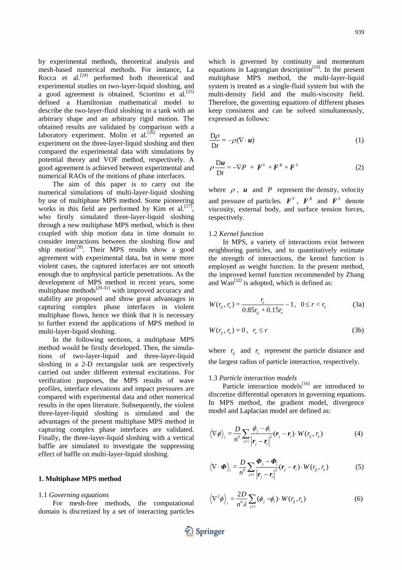
Fig. 1 (Color online) Sketch of two-layer-liquid sloshing sys- tem

941
Fig. 2 (Color online) Snapshots of two-layer-liquid sloshing
neighboring particles of the target particle i . With above modified model, pressure gradient forces between any particles are ensured to be repulsive forces, thus the tensile instability can be eliminated. 1.7 Density smoothing scheme
To deal with the instability caused by density discontinuity across phase interface, we employ a den- sity smoothing scheme[29] in the present multiphase method. In this scheme, the spatial weighted averaging of density is performed for particles near phase interface, according to the following formula
( , )
=( , )
j ij ej I
iij e
j I
W r r
W r r
(14)
where I includes target particle i and its neighboring particles. After smoothing, the continuous transition between densities of different phases can be realized. 1.8 Inter-particle viscosity model In order to consider the viscous force between different phases, the concept of inter-particle viscosity is introduced. Specifically, when particles belonging to different phase interact with each other, the inter- particle viscosity[29] is utilized to substitute the real viscosities. The value of inter-particle viscosity can be obtained by averaging of different viscosities
1/+
=2
i jij
(15)
Fig. 3 (Color online) Comparison of interfacial wave elevations and dynamic pressures in two-layer-liquid sloshing

942
where ij is inter-particle viscosity, i and j
are dynamic viscosities of different particles, is a parameter representing different averaging methods: for = 1 , arithmetic mean is adopted, for = 1 , harmonic mean is adopted. According to the numerical tests by Shakibaeinia and Jin[29], the MPS results show the best agreement with theoretical solutions in the harmonic mean cases, with which the viscosity term can be calculated as
20
22= = ( ) ( , )
+i jV
j i ij ej i i j
DW r r
n
F u u u
(16) 1.9 Surface tension model For violent sloshing flows, the surface tension force is helpful to prevent unphysical penetrations between different phases and obtain a natural and clear interface. In the present method, the continuum surface force (CSF) model[35] is followed, in which the surface tension force is converted into a kind of body force for particles near phase interface, and can be calculated as
=S C F (17)
where is surface tension coefficient, is interface curvature, C is the gradient of color function. To keep the continuity of surface tension forces, a density-weighted color function[36] is adopted here:
= 0ijC , i and j are the same phase (18a)
2
=+
iij
i j
C
, i and j are different phases (18b)
To calculate the interface curvature, an analytical
method developed in contoured continuum surface Fig. 4 (Color online) Sketch of three-layer-liquid sloshing sys-
tem
Fig. 5 (Color online) MPS snapshots of three-layer-liquid slo-
shing for roll motion with 1° amplitude at 1.83 rad/s
Fig. 6 (Color online) MPS snapshots of three-layer-liquid slo-
shing for sway motion with 0.01 m amplitude at 3.62 rad/s
force (CCSF) model[37] is used here. The main idea of CCSF model is to approximate phase interfaces by

943
contours of color function. In first step, the smoothed color function f at an arbitrary location ( , )x y is obtained by a spatial weighted averaging:
s
s
( , )( , ) =
( , )
j ijj
ijj
C G r rf x y
G r r
(19)
2
s 2 2
99( , ) = exp ij
ijs s
rG r r
r r
(20)
Then, the local contours passing by particle i can be obtained through a Taylor series expansion
2, , ,
1( ) + ( ) + ( ) +
2x i i y i i xx i if x x f y y f x x
2, ,
1 ( )( ) + ( ) = 0
2xy i i i yy i if x x y y f y y (21)
where subscripts x and y represent partial de-
rivatives with respect to x and y directions,
respectively. Finally, the interface curvature at particle i is analytically calculated as
2 2, , , , , , ,
3/2 2 2 3/2, ,
2= =
(1+ ) ( + )x i y i xy i x i yy i y i xx i
ii x i y i
f f f f f f fy
y f f
(22)
1.10 Multiphase collision model When two particles get too close, the uniform
particles distribution may be damaged and the unphy- sical penetrations occur. In the present method, the
multiphase collision model[29] is employed to exert additional repulsive forces if the particle distance is below a certain threshold. In this model, the particle collision is regarded as the collision of two spheres with different masses. Initially, all particles are arranged with a constant distance 0l . Once the
distance is smaller than times of 0l in simulation, the collision is assumed to happen and the velocities of particles are corrected based on following equations:
1= (1+ )
+n
i i ij
i j
i i j
u u u (23)
1= + (1+ )
+n
j j ij
i j
j i j
u u u (24)
where iu is velocity vector after collision, n
iju is
relative velocity of i and j along the normal
direction, ε is collision ratio. In this study, = 0.5 is used. 2. Numerical results and discussion 2.1 Validation: Two-layer-liquid sloshing
In this section, the two-layer-liquid sloshing is firstly simulated by the developed multiphase MPS method and the results are compared with experiment by Xue et al.[38]. Figure 1 shows the sketch of experi- mental device. Two immiscible fluids are located in a
Fig. 7 (Color online) Time history of interfacial wave elevations at left wall in three-layer-liquid sloshing with different excitation frequencies
944
2-D rectangular tank. Driven by the external excitation, the tank performs a roll motion with an amplitude of 0.01 m and a frequency of 7.57 rad/s. The heavier liquid is water with 0.10 m deepness and at the upper layer, the diesel oil with 0.05 m deepness is arranged. The physical properties of two fluids are listed in Table 1. The computational domain is dis- cretized by particles with initial distance of 0.002 m, thus total number of particles is 26 724. Three wave probes are arranged at middle 1( ) , left 2( ) and
right 3( ) side of tank, respectively, and three pressure probes (P1, P2, P3) are installed at right wall.
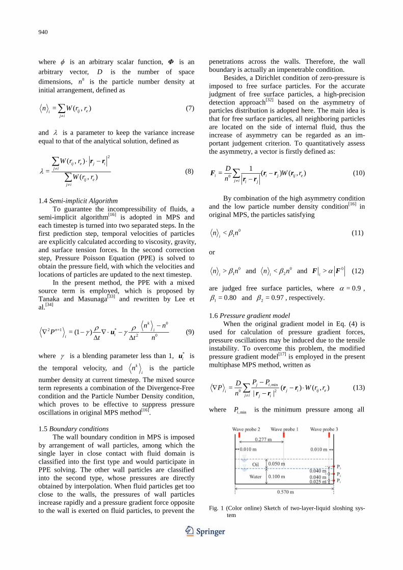
Fig. 8 (Color online) Comparison of interfacial wave elevations for roll motion with 1 amplitude at 1.83 rad/s
Table 1 Physical properties of fluids
Fluid Density Dynamic viscosity
Surface tension coefficient
Diesel oil (0#) 846.2 kg/m3 4.5102 m2/s 0.0330 N/m
Water 1 000.0 kg/m3 1.0103 m2/s 0.0727 N/m
Figure 2 shows the snapshots of two-layer-liquid sloshing obtained by the present multiphase MPS method and experiment[38] at several typical time
instants. As it can be observed, an obvious difference exists between the profiles of interfacial wave and free surface wave, which is an important hydrodynamic characteristics of stratified liquid sloshing. In general, the numerical results show a good agreement with experiment on profiles of both free surface and phase interface, through which the capacity of multiphase MPS method can be validated.
In Fig. 3, the comparison of interfacial wave elevations and dynamic pressures in two-layer-liquid sloshing is carried out. It can be seen that the inter- facial wave elevation at middle of tank is obviously smaller than that at left and right walls, where the two evolution curves are anti-symmetric and a beating phenomenon can be observed. On the whole, the MPS results agree well with IVOF simulation[38] and expe- rimental data[38], especially with the former. Meantime, a good agreement is also obtained on the evolutions of dynamic pressures. Only a slight discrepancy appears in the region where the dynamic pressure is relatively smaller, which may be induced by the less effec- tiveness of pressure sensor for small dynamic pressure in experiment.
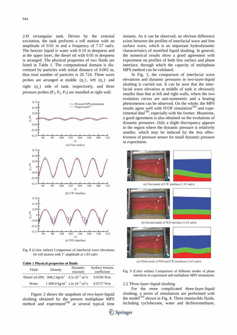
Fig. 9 (Color online) Comparison of different modes of phase
interfaces in experiment and multiphase MPS simulations 2.2 Three-layer-liquid sloshing For the more complicated three-layer-liquid sloshing, a series of simulations are performed with the model[26] shown in Fig. 4. Three immiscible fluids, including cyclohexane, water and dichloromethane,

945
are contained in the tank, with the physical properties given in Table 2. Thus, two phase interfaces exist besides the free surface (FS), called cyclohexane- water (CW) interface and water- dichloromethane (WD) interface. The tank is able to perform either sway or roll motion. In this section, two cases with different tank motions are considered. In case 1, the tank performs a sway motion with an amplitude of 0.01 m and a frequency of 1.83 rad/s. In case 2, the tank performs a roll motion with an amplitude of 1 and a frequency of 3.62 rad/s. Table 2 Physical properties of fluids
Fluid Density Dynamic viscosity
Surface tension coefficient
Cyclohexane 780 kg/m3 1.014103 m2/s 0.00247 N/m
Water 1 000 kg/m3 1.0103 m2/s 0.07270 N/m
Dichloromethane 1 300 kg/m3 3.9104 m2/s 0.02780 N/m
Figures 5, 6 present the MPS snapshots of
three-layer-liquid sloshing in two cases. As it can be observed, the first mode of CW interface is excited in case 1, because the frequency of roll motion is close to first natural frequency of the middle layer[26]. While,
Fig. 12 (Color online) Comparison of phase interfaces captured
by different multiphase MPS methods in case 2, the third mode of CW interface is captured as the frequency of sway motion increases to the third natural frequency of the middle layer.
Moreover, the different excitation frequencies also induce a discrepancy on the interfacial wave ele- vations, as shown in Fig. 7. In case 1, the elevation of
Fig. 10 (Color online) Snapshots of three-layer-liquid sloshing with 3 roll amplitude at 1.83 rad/s and 0.04 m sway amplitude at 3.62 rad/s
Fig. 11 (Color online) Time history of interfacial wave elevations at the left tank wall in violent three-layer-liquid sloshing

946
free surface reaches a steady state soon, while the elevations of CW and WD interfaces are much larger and keep growing until = 90 st due to the appearance of first mode. In case 2, both free surface and phase interfaces reach a steady state soon at = 30 st , but the elevation of free surface is larger than that of CW and WD interfaces due to the appearance of third mode.
The calculated elevations of free surface and phase interfaces are compared with experimental data[26] in Fig. 8, showing a good agreement. Moreover, as
shown in Fig. 9, the different modes of phase interfaces in multiphase MPS simulations also keep consistent with experimental pictures. 2.3 Violent three-layer-liquid sloshing
In this section, the violent three-layer-liquid slo- shing is further studied, in which the tank motion is bichromatic, with a sway motion and a roll motion at the same time. The amplitude and frequency of the sway motion are 0.04 m and 3.62 rad/s, and that of the roll motion are 3 and 1.83 rad/s.
Fig. 13 (Color online) MPS snapshots of the three-layer-liquid sloshing without baffles or with vertical baffles of three different heights
947
From the snapshots in Fig. 10, the first, second and third modes of CW interface are all observed. Due to the increase of sloshing intensity, the breaking of internal wave occurs at about = 90 st . Figure 11 shows the evolution of interfacial wave elevations. In the present case, both the free surface and phase interfaces experience large elevations. In particular, the deformation of free surface becomes complex due to the formation of multiple free surface waves. Figure 12 compares the phase interfaces captured by the present method to the MPS results by Kim et al.[27]. The waveforms are in good agreement, but the phase interfaces in the present simulation are smoother and there are no unphysical penetrations between different phases, validating the accuracy of the multiphase MPS method in this paper.
2.4 Sloshing with a vertical baffle To suppress the sloshing in single-phase flows, a
baffle is usually installed inside the tank. For a further investigation on the suppressing effect of baffle in multiphase flows, the three-layer-liquid sloshing with a vertical baffle is studied in this section. The model is similar to the one in Fig. 4, but with a vertical baffle at
the middle of tank bottom. To analyze the influence of baffle height, three different heights bh , including
0.075 m, 0.225 m and 0.490 m, are respectively consi- dered. In all cases, the tank performs a roll motion with an amplitude of 3 and a frequency of 1.83 rad/s.
From Fig. 13, it can be seen that the vertical baffle could significantly reduce the intensity of slo- shing. In the case of b = 0.075 mh , the sloshing of the
lowest layer is well inhibited, while the sloshing of the middle layer is still violent. Meantime, when the lowest liquid passes through the baffle, a hydro jump is formed and cause deformation of WD interface. As the baffle height increases to 0.225 m or 0.490 m, the sloshing of all layers is inhibited, thus the free surface and phase interfaces remain nearly horizontal.
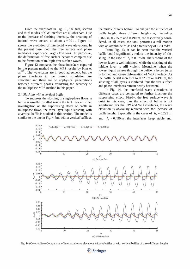
In Fig. 14, the interfacial wave elevations in different cases are compared to further illustrate the suppressing effect. Firstly, the free surface wave is quiet in this case, thus the effect of baffle is not significant. For the CW and WD interfaces, the wave elevation is obviously reduced with the increase of baffle height. Especially in the cases of b = 0.225 mh and b = 0.490 mh , the interfaces keep stable and
Fig. 14 (Color online) Comparison of interfacial wave elevations without baffles or with vertical baffles of three different heights

948
almost unchanged during the entire simulation, indica- ting that the sloshing wave has been fully inhibited.
3. Conclusions
In this paper, a multiphase MPS method is deve- loped and successfully applied to simulate the multi- layer-liquid sloshing. The following conclusions can be drawn from the work here: (1) Numerical algorithms of the multiphase MPS method are introduced in detail, and through the simu- lation of two-layer-liquid sloshing, its accuracy is well validated. The numerical results, including the wave profiles, interface elevations and impact pressures, show a good agreement with experimental data and other numerical results. (2) A series of three-layer-liquid sloshing are simulated and various modes of phase interfaces are found under different excitation frequencies. It is observed that the phase interfaces may suffer from complex deformations while the free surface keeps relatively quiet. Beneficial from the Lagrangian basis of MPS method, both free surface and phase interfaces are accurately captured and the phenomenon of internal wave breaking is well reproduced.
(3) The suppressing effect of baffle on the multi- layer-liquid sloshing is validated through the simula- tion of three-layer-liquid sloshing with a vertical baffle. From the comparison with the case without baffle, it shows that the vertical baffle is able to significantly reduce the sloshing intensity and limit the interfacial wave elevations. Moreover, As the height of baffle increases, the suppressing effect grows stronger rapidly. References [1] Frandsen J. B. Sloshing motions in excited tanks [J].
Journal of Computational Physics, 2004, 196(1): 53-87. [2] Zhao W., Yang J., Hu Z. et al. Coupled analysis of non-
linear sloshing and ship motions [J]. Applied Ocean Research, 2014, 47: 85-97.
[3] Wei Z. J., Faltinsen O. M., Lugni C. et al. Sloshing- induced slamming in screen-equipped rectangular tanks in shallow-water conditions [J]. Physics of Fluids, 2015, 27(3): 032104.
[4] Seo M. G., Kim Y., Park D. M. Effect of internal sloshing on added resistance of ship [J]. Journal of Hydrodynamics, 2017, 29(1): 13-26.
[5] Li Y. L., Zhu R. C., Miao G. P. et al. Simulation of tank sloshing based on OpenFOAM and coupling with ship motions in time domain [J]. Journal of Hydrodynamics, 2012, 24(3): 450-457.
[6] Rognebakke O. F., Faltinsen O. M. Coupling of sloshing and ship motions [J]. Journal of Ship Research, 2003, 47(3): 208-221.
[7] Stephen J. J., Sannasiraj S. A., Sundar, V. Numerical modeling of nonlinear sloshing of liquid in a container coupled with barge subjected to regular excitation [J].
Journal of Hydrodynamics, 2019, 31(5): 999-1010. [8] Ming P. J., Duan W. Y. Numerical simulation of sloshing
in rectangular tank with VOF based on unstructured grids [J]. Journal of Hydrodynamics, 2010, 22(6): 856-864.
[9] Bai W., Liu X., Koh C. G. Numerical study of violent lng sloshing induced by realistic ship motions using level set method [J]. Ocean Engineering, 2015, 97: 100-113.
[10] Hu C. H., Kamra M. M. An unstructured mesh method for numerical simulation of violent sloshing flows [J]. Journal of Hydrodynamics, 2020, 32(2): 259-266.
[11] Khayyer A., Gotoh H. Enhancement of stability and accuracy of the moving particle semi-implicit method [J]. Journal of Computational Physics, 2011, 230(8): 3093- 3118.
[12] Wang L., Wang Z., Li Y. A SPH simulation on large- amplitude sloshing for fluids in a two-dimensional tank [J]. Earthquake Engineering and Engineering Vibration, 2013, 12(1): 135-142.
[13] Zhang Y. X., Wan D. C., Takanori H. Comparative study of MPS method and level-set method for sloshing flows [J]. Journal of Hydrodynamics, 2014, 26(4): 577-585.
[14] Lucy L. A numerical approach to the testing of the fission hypothesis [J]. The Astronomical Journal, 1977, 8(12): 1013-1024.
[15] Monaghan J. J. Simulating free surface flows with SPH [J]. Journal of Computational Physics, 1994, 110(2): 399-406.
[16] Koshizuka S., Oka Y. Moving-particle semi-implicit me- thod for fragmentation of incompressible fluid [J]. Nuclear Science and Engineering, 1996, 123(3): 421-434.
[17] Koshizuka S., Nobe A., Oka Y. Numerical analysis of breaking waves using the moving particle semi-implicit method [J]. International Journal for Numerical Methods in Fluids, 1998, 26: 751-769.
[18] Hwang S. C., Park J. C., Gotoh H. et al. Numerical simu- lations of sloshing flows with elastic baffles by using a particle-based fluid-structure interaction analysis method [J]. Ocean Engineering, 2016, 118: 227-241.
[19] Zhang Y. X., Wan D. C., Hino T. Comparative study of MPS method and Level-Set method for sloshing flows [J]. Journal of Hydrodynamics, 2014, 26(4): 577-585.
[20] Khayyer A., Gotoh H. A higher order Laplacian model for enhancement and stabilization of pressure calculation by the MPS method [J]. Applied Ocean Research, 2012, 32: 124-131.
[21] Lee B. H., Jeong S. M., Hwang S. C. et al. A particle simulation of 2D vessel motions interacting with liquid- sloshing cargo [J]. Computer Modeling in Engineering and Sciences, 2013, 91(1): 43-63.
[22] Chen X., Zhang Y., Wan D. Numerical study of 3-D liquid sloshing in an elastic tank by MPS-FEM coupled method [J]. Journal of Ship Research, 2019, 63(3): 143-153.
[23] Xie F. Z., Zhao W. W., Wan D. C. CFD simulations of three-dimensional violent sloshing flows in tanks based on MPS and GPU [J]. Journal of Hydrodynamics, 2020, 32(4): 672-683.
[24] La Rocca M., Sciortino G., Adduce C. Experimental and theoretical investigation on the sloshing of a two-liquid system with free surface [J]. Physics of Fluids, 2005, 17(6): 062101.
[25] Sciortino G., Adduce C., Rocca M. L. Sloshing of a layered fluid with a free surface as a hamiltonian system [J]. Physics of Fluids, 2009, 21(5): 052102.
[26] Molin B., Remy F., Audiffren C. et al. Experimental and numerical study of liquid sloshing in a rectangular tank with three fluids [C]. Proceedings of the 22nd International Offshore and Polar Engineering Conference

949
(ISOPEʼ12), Rhodes, Greece, 2012, 331-340. [27] Kim K. S., Kim M. H., Park J. C. Development of moving
particle simulation method for multiliquid-layer sloshing [J]. Mathematical Problems in Engineering, 2014, ID350165.
[28] Kim K. S., Kim M. H., Park J. C. Dynamic coupling between ship motion and three-layer-liquid separator by using moving particle simulation [J]. International Journal of Offshore and Polar Engineering, 2014, 24(2): 122-128.
[29] Shakibaeinia A., Jin Y. MPS mesh-free particle method for multiphase flow [J]. Computer Methods in Applied Mechanics and Engineering, 2012, 229: 13-26.
[30] Khayyer A., Gotoh H. Enhancement of performance and stability of MPS mesh-free particle method for multiphase flows characterized by high density ratios [J]. Journal of Computational Physics, 2013, 242: 211-233.
[31] Duan G., Koshizuka S., Chen B. et al. Stable multiphase moving particle semi-implicit method for incompressible interfacial flow [J]. Computer Methods in Applied Mechanics and Engineering, 2017, 318: 636-666.
[32] Zhang Y. X., Wan D. C. Numerical simulation of liquid sloshing in low-filling tank by MPS [J]. Chinese Journal of Hydrodynamics, 2012, 27(1): 100-107(in Chinese).
[33] Tanaka M., Masunaga T. Stabilization and smoothing of pressure in MPS method by quasi-compressibility [J]. Journal of Computational Physics, 2010, 229(11): 4279-4290.
[34] Lee B. H., Park J. C., Kim M. H. et al. Step-by-step improvement of MPS method in simulating violent free-surface motions and impact-loads [J]. Computer Methods in Applied Mechanics and Engineering, 2011, 200(9-12): 1113-1125.
[35] Brackbill J. U., Kothe D. B., Zemach C. A continuum method for modeling surface tension [J]. Journal of Computational Physics, 1992, 100(2): 335-354.
[36] Zhang A., Sun P., Ming F. An SPH modeling of bubble rising and coalescing in three dimensions [J]. Computer Methods in Applied Mechanics and Engineering, 2015, 294: 189-209.
[37] Duan G., Koshizuka S., Chen B. A contoured continuum surface force model for particle methods [J]. Journal of Computational Physics, 2015, 298: 280-304.
[38] Xue M., Zheng J., Lin P. et al. Experimental investigation on the layered liquid sloshing in a rectangular tank [C]. Proceedings of the 23nd International Offshore and Polar Engineering Conference (ISOPEʼ13), Anchorage, Alaska, USA, 2013, 202-208.