numerical simulation on ground vibration caused by the
TRANSCRIPT

288 © JVE INTERNATIONAL LTD. VIBROENGINEERING PROCEDIA. DEC 2016, VOL. 10. ISSN 2345-0533
Numerical simulation on ground vibration caused by the demolition of a 200 m high chimney
Wenming Jiang1, Feng Lin2 Department of Structural Engineering, Tongji University, Shanghai, China 2Corresponding author E-mail: [email protected], [email protected] (Received 10 August 2016; accepted 12 August 2016)
Abstract. A chimney-soil model was built using finite element method to simulate the demolition of a chimney and the subsequent ground vibration. The acceleration history of ground vibration at observed point was obtained. The simulated results were compared with on-site measured data and good agreement was found with errors of less than 2.88 % for maximum acceleration amplitudes. It was also demonstrated that the element disappearance in the model did not affect the vibration response. Keywords: chimney demolition, ground vibration, controlled blasting.
1. Introduction
A 200 m height chimney located in Shanghai, China, was demolished by controlled blasting in a pre-specified direction. As generally known, the collapsed chimney impacts ground and induces intensive ground vibration which may detrimentally affect the adjacent facilities and buildings [1]. In this regard, prediction of the ground vibration with reasonable accuracy was commonly required before chimney demolition.
The methods to predict the demolition-induced ground vibration usually fall into two categories. One is the empirical formulae based on an amount of on-site measured data. The other is numerical approach based on finite element method (FEM) with considerable numerical efforts. These empirical formulae are usually expressed in forms of maximum ground velocities. A ground motion history is unavailable using empirical formulae, however, can be obtained using a numerical simulation.
This paper presents a comprehensive numerical model to predict the ground vibration due to the demolition of the tall chimney. The predicted results were compared with the field measured data. Model details were presented and the rationality and limitations of the model were also discussed.
2. On-site measurement
2.1. Chimney and soil
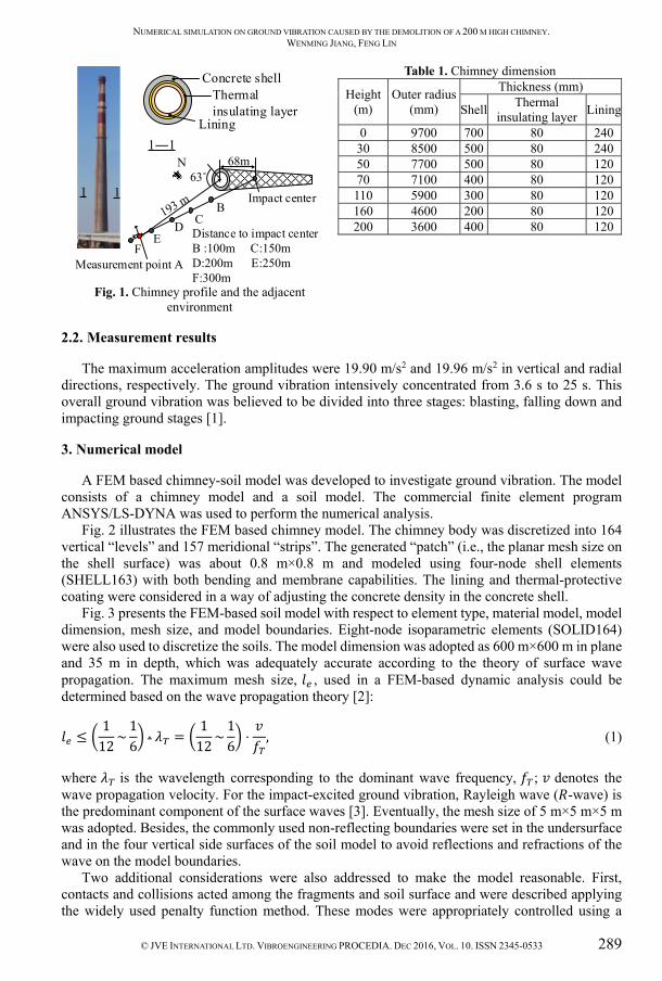
Fig. 1 illustrates the chimney profile and the adjacent environment. The 200 m high chimney was primarily constructed using reinforced concrete. Its wall was made up of three layers from the interior to the exterior: lining, thermal-protective coating, and concrete shell. The outer radials and layer thicknesses of the chimney at different elevations were presented in Table 1. The circumferential reinforcement ratios varied from 0.31 % to 1.1 % on inner side and from 1.1 % to 3.3 % on outer side, respectively. Similarly, the vertical reinforcement ratios ranged from 0.33 % to 1.3 % and from 1.1 % to 2.4 % on inner and outer sides, respectively. The uniaxial compressive strength of concrete was 29.6 MPa, and the yield strength of reinforcing steel bars was 400 MPa. The site was typically coastal soils in China. The top layered soil was silty clay (8.8 m thickness).
The directional collapse of the chimney was achieved using a “notch” with specific dimension and position. The “notch” was produced by explosive embedded in the holes which were drilled in the chimney wall. The notch was in a form of trapezoid with a height of 4 m, upside length of 28.61 m, and lower side length of 35.61 m
NUMERICAL SIMULATION ON GROUND VIBRATION CAUSED BY THE DEMOLITION OF A 200 M HIGH CHIMNEY. WENMING JIANG, FENG LIN
© JVE INTERNATIONAL LTD. VIBROENGINEERING PROCEDIA. DEC 2016, VOL. 10. ISSN 2345-0533 289
Concrete shellThermal insulating layer
Lining1―1
1 1
Distance to impact centerB :100m C:150mD:200m E:250mF:300m
63˚N
Impact center
68m
BC
FE
D
Measurement point A
Fig. 1. Chimney profile and the adjacent environment
Table 1. Chimney dimension
Height (m)
Outer radius (mm)
Thickness (mm)
Shell Thermal insulating layer Lining
0 9700 700 80 240 30 8500 500 80 240 50 7700 500 80 120 70 7100 400 80 120 110 5900 300 80 120 160 4600 200 80 120 200 3600 400 80 120
2.2. Measurement results
The maximum acceleration amplitudes were 19.90 m/s2 and 19.96 m/s2 in vertical and radial directions, respectively. The ground vibration intensively concentrated from 3.6 s to 25 s. This overall ground vibration was believed to be divided into three stages: blasting, falling down and impacting ground stages [1].
3. Numerical model
A FEM based chimney-soil model was developed to investigate ground vibration. The model consists of a chimney model and a soil model. The commercial finite element program ANSYS/LS-DYNA was used to perform the numerical analysis.
Fig. 2 illustrates the FEM based chimney model. The chimney body was discretized into 164 vertical “levels” and 157 meridional “strips”. The generated “patch” (i.e., the planar mesh size on the shell surface) was about 0.8 m×0.8 m and modeled using four-node shell elements (SHELL163) with both bending and membrane capabilities. The lining and thermal-protective coating were considered in a way of adjusting the concrete density in the concrete shell.
Fig. 3 presents the FEM-based soil model with respect to element type, material model, model dimension, mesh size, and model boundaries. Eight-node isoparametric elements (SOLID164) were also used to discretize the soils. The model dimension was adopted as 600 m×600 m in plane and 35 m in depth, which was adequately accurate according to the theory of surface wave propagation. The maximum mesh size, , used in a FEM-based dynamic analysis could be determined based on the wave propagation theory [2]:
≤ 112 ~ 16 ⋅ = 112 ~ 16 ⋅ , (1)
where is the wavelength corresponding to the dominant wave frequency, ; denotes the wave propagation velocity. For the impact-excited ground vibration, Rayleigh wave ( -wave) is the predominant component of the surface waves [3]. Eventually, the mesh size of 5 m×5 m×5 m was adopted. Besides, the commonly used non-reflecting boundaries were set in the undersurface and in the four vertical side surfaces of the soil model to avoid reflections and refractions of the wave on the model boundaries.
Two additional considerations were also addressed to make the model reasonable. First, contacts and collisions acted among the fragments and soil surface and were described applying the widely used penalty function method. These modes were appropriately controlled using a

NUMERICAL SIMULATION ON GROUND VIBRATION CAUSED BY THE DEMOLITION OF A 200 M HIGH CHIMNEY. WENMING JIANG, FENG LIN
290 © JVE INTERNATIONAL LTD. VIBROENGINEERING PROCEDIA. DEC 2016, VOL. 10. ISSN 2345-0533
viscous damping and small elastic stiffness. Second, specific elements were killed after a pre-defined time to simulate the generation of the notch.
Concrete
Circumferential reinforcement
Meridionalreinforcement
Shell element
Fig. 2. Chimney model
Fig. 3. Soil model
4. Comparison of measured and simulated results
Fig. 4 presents the collapse process of the chimney. The collapse profiles and collapse duration were both well simulated. Fig. 5 compares the on-site measured and simulated acceleration histories of ground vibration at point A. The vibration in “blasting” stage was not simulated because the actual TNT equivalent and the effect of explosion on ground vibration were difficult to model. Table 2 also compares the on-site recorded and simulated maximum acceleration amplitudes of ground vibration in point A. The maximum error was about 2.88 % which was quite small. Obviously, well similarity was found between measured and simulated results.
a) = 8 s
b) = 9 s
c) = 10 s
Fig. 4. Collapse of chimney
Table 2. Comparison of the on-site recorded and simulated maximum acceleration amplitudes of ground vibration at point A
Direction Vibration stage Amplitude (× 10-2 m/s2) Time (s) On-site recorded Simulated Error* On-site recorded Simulated
Vertical Falling down 19.10 19.65 2.88 % 10.44 9.59 Impacting ground 10.19 9.93 –2.55 % 21.48 21.97
Radial Falling down –10.92 –11.16 2.20 % 9.58 9.6 Impacting ground 9.06 9.00 –0.67 % 21.62 21.03
*Error = (simulated value-on-site recorded value) / on-site recorded value

NUMERICAL SIMULATION ON GROUND VIBRATION CAUSED BY THE DEMOLITION OF A 200 M HIGH CHIMNEY. WENMING JIANG, FENG LIN
© JVE INTERNATIONAL LTD. VIBROENGINEERING PROCEDIA. DEC 2016, VOL. 10. ISSN 2345-0533 291
Fig. 5. On-site measured and simulated acceleration histories of ground vibration at point A
5. Discussions
One issue concerning the rationality of the model was discussed. Most of the debris disappeared after impacting in the model which differed from reality. This was mainly due to the limitation of a FEM-based model. The elements were killed in the model when the materials reached their failure criteria to avoid an interrupt of the computation. However, this visual disadvantage was believed to have no effect on ground vibration. This was demonstrated using a calculation example. Fig. 6 illustrated a FEM-based model consisted of two parts: a reinforced concrete cylinder shell and the soil. The cylinder shell’s radius and depth were 3 m and 10 m respectively. The soil dimension was adopted as 300 m×300 m in plane and 50 m in depth. Element type and material model for cylinder shell and soil were the same as those in previous chimney model. The keyword*MAT_ADD_ERROSION was used for cylinder shell. In the calculation, the cylinder shell impacted the soil with different initial velocities. The results indicated that the elements for cylinder shell began to be killed at 10 m/s.
Fig. 7 presents the maximum velocity amplitudes for ground vibration at point G in vertical direction. Results found that the maximum velocity amplitudes increased with the increase in initial impact velocity. These results seemed to be reasonable indicating the rationality of the model.
Fig. 6. FEM for calculation example
Fig. 7. Maximum amplitudes for different velocities
6. Conclusions
An FEM-based chimney-soil model was built to predict the demolition of the chimney by
-20
-10
0
10
20
0 5 10 15 20 25
a (×
10-2
m/s
-2)
t (s)
vertical
on-site measuredsimulated
-20
-10
0
10
20
0 5 10 15 20 25
a (×
10-2
m/s
-2)
t (s)
radial
on-site measuredsimulated

NUMERICAL SIMULATION ON GROUND VIBRATION CAUSED BY THE DEMOLITION OF A 200 M HIGH CHIMNEY. WENMING JIANG, FENG LIN
292 © JVE INTERNATIONAL LTD. VIBROENGINEERING PROCEDIA. DEC 2016, VOL. 10. ISSN 2345-0533
controlled blasting. The simulated results were compared with the on-site measured ones in form of acceleration history of ground vibration at the observed point. The collapse process and the ground vibration in falling down and impacting ground stages were well simulated. The errors of maximum acceleration amplitudes were less than 2.88 %. It also seemed that the element disappearance had no effect on the results of ground vibration.
References
[1] Jiang Y. G., Shen Z. W., Gong Z. G. Vibration law of structure blasting demolition. Journal of Vibration and Shock. Vol. 31, Issue 5, 2012, p. 36-41.
[2] Kausel E., Manolis G. Wave Motion in Earthquake Engineering. WIT Press, Boston, 2000. [3] Bolt B. A. Earthquake. Freeman, New York, 1988.