numerical investigation of thermally induced birefringence in optical elements of solid-state lasers
TRANSCRIPT

Numerical investigationof thermally induced birefringencein optical elements of solid-state lasers
Vladimir Parfenov, Vladimir Shashkin, and Eugene Stepanov
We have developed a method of computational simulation and estimation of thermo-optical distortions insolid-state laser rods, electro-optic shutters, and modulators, considering real heat-transfer conditions,anisotropic material properties, and an arbitrary cross-section shape of the element. Numericalinvestigations for Nd:YAG laser rods and potassium dihydrogen phosphate electro-optic shutters havebeen carried out, new results have been obtained, and known analytical solutions have been corrected.
Key words: Depolarization, thermally induced birefringence, electro-optic shutter, laser rod.
IntroductionInhomogeneous temperature fields in optical ele-ments give rise to thermal stresses, which, because ofthe photoelastic effect, impair the optical characteris-tics. The subjects of this paper are components suchas solid-state laser rods, electro-optic devices workingon the basis of the Pockels effect (shutters, modula-tors, deflectors), and others, in which impairment oftheir optical characteristics is caused mainly by ther-mally induced birefingence. Temperature fields thatcause distortions can result from, for example, heatsources appearing as a consequence of volume- andsurface-absorbing radiation of optical pumping (laserrods), laser-generated radiation (such as electro-opticlight modulators, and crystals for second-harmonicgeneration), and acoustic waves (acousto-optic deflec-tors). The analogous processes are to be consideredin polarization mechanics.
Many papers have been devoted to experimentaland theoretical investigations of how the photoelasticeffect reveals itself in different optical elements.'- 9
However, the theoretical results obtained have beenbased on analytical methods and hence have dealtwith a limited number of practical situations, mainlybecause of the difficulties encountered in the numeri-cal solution of the thermoelasticity problem.
The authors are with the Department of Computer Technology,St. Petersburg Institute of Fine Mechanics and Optics, 14 Sablin-skaya ulitsa, St. Petersburg, 197101, Russia.
Received 4 December 1991.0003-6935/93/275243-13$06.00/0.t© 1993 Optical Society of America.
Usually optical elements are regarded either aslong rods or as thin disks. In previous consider-ations of this problem the following assumptionswere made:
1. Only elements with circular cross sections (i.e.,cylinders) were considered.
2. The intensity distribution of a light beampassing along the element axis was considered to beuniform.
3. The temperature field of the element was con-sidered to depend only on the radial coordinate (i.e., auniform inner heat sources distribution was assumed).In practice optical elements often have square crosssections, light beams are never uniform, and temper-ature fields depend on both radial and angular coordi-nates.
In this paper we propose a method of numericalsimulation and estimation of thermo-optical distor-tions in such elements that is free from the above-mentioned restrictions. We also present the resultsof the numerical investigation of Nd:YAG laser rodsand potassium dihydrogen phosphate (KDP) electro-optic shutters.
Mathematical Model and Main Aspectsof Its Numerical RealizationConsider an optical element that is either a long rodor a thin disk heated nonuniformly either by a lightbeam passing through it or by an external light source(such as a flash lamp in the case of a laser rod).Cartesian coordinate axes are directed with the z axisparallel to geometrical axis of the element, the x andy
20 September 1993 / Vol. 32, No. 27 / APPLIED OPTICS 5243
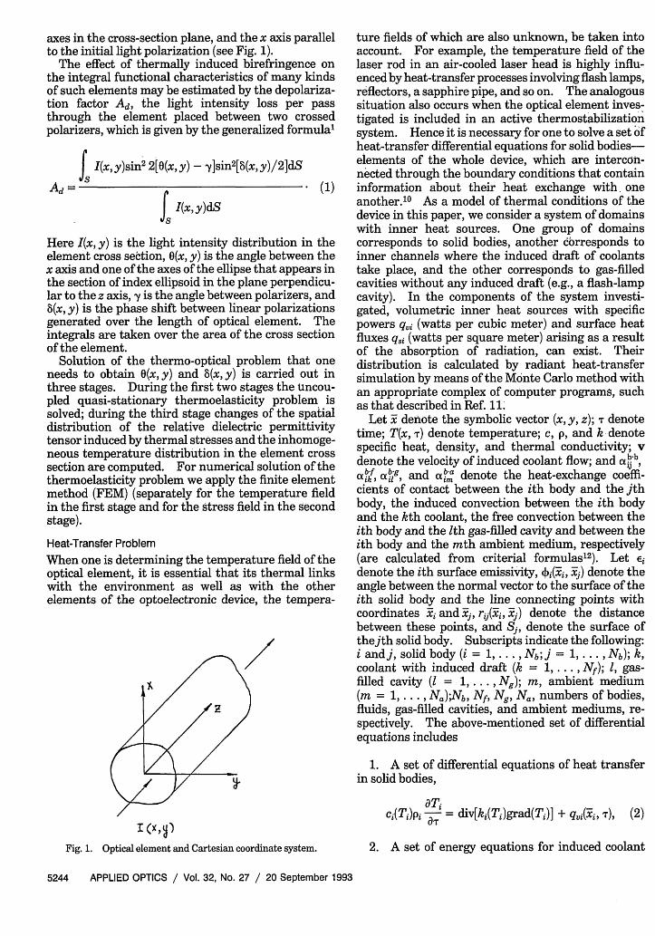
axes in the cross-section plane, and the x axis parallelto the initial light polarization (see Fig. 1).
The effect of thermally induced birefringence onthe integral functional characteristics of many kindsof such elements may be estimated by the depolariza-tion factor Ad, the light intensity loss per passthrough the element placed between two crossedpolarizers, which is given by the generalized formula'
Ad =
f I(x, y)sin2 2[0(x,y) - y]sin2[8(xy)/2]dSs
fsI(x, y)dS
Here I(x, y) is the light intensity distribution in theelement cross section, O(x, y) is the angle between thex axis and one of the axes of the ellipse that appears inthe section of index ellipsoid in the plane perpendicu-lar to the z axis, y is the angle between polarizers, and8(x, y) is the phase shift between linear polarizationsgenerated over the length of optical element. Theintegrals are taken over the area of the cross sectionof the element.
Solution of the thermo-optical problem that oneneeds to obtain (x, y) and (x, y) is carried out inthree stages. During the first two stages the uncou-pled quasi-stationary thermoelasticity problem issolved; during the third stage changes of the spatialdistribution of the relative dielectric permittivitytensor induced by thermal stresses and the inhomoge-neous temperature distribution in the element crosssection are computed. For numerical solution of thethermoelasticity problem we apply the finite elementmethod (FEM) (separately for the temperature fieldin the first stage and for the stress field in the secondstage).
Heat-Transfer ProblemWhen one is determining the temperature field of theoptical element, it is essential that its thermal linkswith the environment as well as with the otherelements of the optoelectronic device, the tempera-
Fig. 1. Optical element and Cartesian coordinate system.
ture fields of which are also unknown, be taken intoaccount. For example, the temperature field of thelaser rod in an air-cooled laser head is highly influ-enced by heat-transfer processes involving flash lamps,reflectors, a sapphire pipe, and so on. The analogoussituation also occurs when the optical element inves-tigated is included in an active thermostabilizationsystem. Hence it is necessary for one to solve a set 6fheat-transfer differential equations for solid bodies-elements of the whole device, which are intercon-nected through the boundary conditions that containinformation about their heat exchange with oneanother.10 As a model of thermal conditions of thedevice in this paper, we consider a system of domainswith inner heat sources. One group of domainscorresponds to solid bodies, another corresponds toinner channels where the induced draft of coolantstake place, and the other corresponds to gas-filledcavities without any induced draft (e.g., a flash-lampcavity). In the components of the system investi-gated, volumetric inner heat sources with specificpowers qvi (watts per cubic meter) and surface heatfluxes q~j (watts per square meter) arising as a resultof the absorption of radiation, can exist. Theirdistribution is calculated by radiant heat-transfersimulation by means of the Monte Carlo method withan appropriate complex of computer programs, suchas that described in Ref. 11.
Let x- denote the symbolic vector (x, y, z); T denotetime; T(x, r) denote temperature; c, p, and k denotespecific heat, density, and thermal conductivity; vdenote the velocity of induced coolant flow; and a!b,a'4, obig, and 'm denote the heat-exchange coeffi-cients of contact between the ith body and the jthbody, the induced convection between the ith bodyand the kth coolant, the free convection between theith body and the Ith gas-filled cavity and between theith body and the mth ambient medium, respectively(are calculated from criterial formulas' 2 ). Let idenote the ith surface emissivity, 4)#Yi, x-j) denote theangle between the normal vector to the surface of theith solid body and the line connecting points withcoordinates xi and -, rij(Yi, j) denote the distancebetween these points, and Sj, denote the surface ofthejth solid body. Subscripts indicate the following:i and j, solid body (i = 1, . . , Nb; j = 1, . . , Nb); k,coolant with induced draft (k = 1,... , Nf); 1, gas-filled cavity (I = 1, ... , Ng); m, ambient medium(m = 1, . . Na);Nb, Nf, Ng, Na, numbers of bodies,fluids, gas-filled cavities, and ambient mediums, re-spectively. The above-mentioned set of differentialequations includes
1. A set of differential equations of heat transferin solid bodies,
ci(Ti)pi ay = div[kj(Tj)grad(Tj)] + qui(j, T), (2)
2. A set of energy equations for induced coolant
5244 APPLIED OPTICS / Vol. 32, No. 27 / 20 September 1993

flows in inner channels,
Ck(Tk)Pk[ d + Vk grad(Tk)]
= div[kk(Tk)grad(Tk)] + qvk(xk, r), (3)
3. A set of balance equations for free convection ingas-filled cavities (their temperatures are consideredto be time independent),
Nb
z f tzbi9(Y, Ti, T1)(Tj - T1)dS, = 0. (4)
This system is also supplied by a set of evident initialconditions,
TI | =O = TOA(X), Tj | T=o = T(X), (5)
and boundary conditions,10
Nb-( = z aXb(y, T,, Tj)(T - T
jgi
Nf
+ .4 bf(Y, Ti, T)(T - TO)k=1
Ng
+ cliig(y, Ti, T1)(Ti - T)
Na
+ z (xjba(Y, Ti, Tm)(Ti- Tm) + qi(Y r)m=1
+ I qj cos[ (#, ]j)]cos[(j3,E,1 Sjrri2g~i Xi
x dSj - EiaT . (6)
The first two terms in Eq. (6) represent conductiveand induced convective heat transfer, the third termrepresents free convection, the fourth term repre-sents the thermal interaction with the environment,and the sum of the fifth, sixth, and seventh is asurface resulting radiative heat flux density from thesurface of the ith solid body, determined underassumption of grey, diffuse emitting-reflecting sur-faces. The effective radiative heat flux densities qiunder this assumption are found from the followingsystem of equations13:
q(X)- (1- ei) I qj cs[(>,(y, j)]cos[(x#, j)]j=1 sI Trilj(yi, j)
= eiUT?. (7)
For the energy equations of the induced coolants flowthe following boundary conditions are set up:
aTk Nb-kk(Tk) y- = I ajbk(Y, Ti, Tk)(Ti - Tk). (8)
When one is considering the cases of specular reflect-ing surfaces, it is necessary to compute the resultingradiative fluxes by means of a method describedrigorously in Ref. 13.
When we investigated temperature fields in electro-optic shutters in the laser rod cooled by an inducedliquid flow (a liquid-cooled laser head), an idealizedsituation was analyzed: only the influences of innerheat sources and the environment (for the shutter),that is, the coolant (for laser rod), on thermal statewere included. So the system of Eqs. (2)-(4) isreduced to one heat-transfer equation for the opticalelement investigated:
c(T)p dT = div[k(T)grad(T)] + q(x, y, )
with boundary condition
T N-k(T) an = j ct(x,y, T, Tj)(T-Tj) + qs(x,y, T) (10)an it
and initial condition
TI= 0 = To(x,y), (11)
where c, p, and k are the specific heat, density, andthermal conductivity of the element material, T is thetime, {Ti}ff is the temperatures of bodies that are inconditions of heat transfer with the element, and q,and q, are volume and surface heating power density.The solution region in this case is two dimensional(element cross section). This equation may be easilysolved by either the partial difference method orFEM.
Now consider principal specific features of thenumerical solution of a system of Eqs. (2)-(4) for themost difficult case, the case of the air-cooled laserhead. During discretizing, the three-dimensional so-lution region (the pumping cavity) is cut by a set ofplanes perpendicular to its axis (z axis). For theelements of the laser head with a regular-shaped(rectangular, circular, or ring-shaped) cross section,such as flash lamps and laser rods, the correspondentregular calculation grid in either Cartesian or polarcoordinates is built automatically. For irregular-shaped elements the correspondent irregular triangu-lar mesh is built semiautomatically with manualcorrection, bearing in mind the evident rules ofthumb:
All triangles should be almost equal sided (theirangles should approach 600), because, as is shown inRef. 14, the precision of the FEM approximation ofthe derivatives of the function being determined isreciprocal to the sine of minimum angle of thetriangle.
The quality of the cross-section discretization as awhole is determined mainly by the quality of thelaser-rod discretization; hence the closer to the laserrod, the smaller the discretitization steps.
An example of the actual three-dimensional grid for
20 September 1993 / Vol. 32, No. 27 / APPLIED OPTICS 5245
(9)
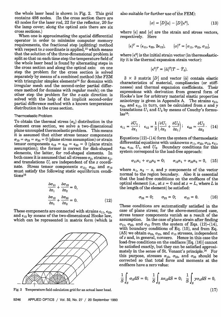
the whole laser head is shown in Fig. 2. This gridcontains 498 nodes. (In the cross section there are43 nodes for the laser rod, 22 for the reflector, 20 forthe lamp cover; along the optical axis there are sixcross sections.)
When one is approximating the spatial differentialoperator in order to minimize computer memoryrequirements, the fractional step (splitting) methodwith respect to z coordinate is applied,' 5 which meansthat the solution of the three-dimensional problem issplit so that on each time step the temperature field ofthe whole laser head is found by alternating steps inthe cross section and along the optical axis: on onestep the problem for the cross section is solvedseparately by means of a combined method (the FEMwith triangular simplex elements'4 for domains withirregular mesh and the second-order partial differ-ence method for domains with regular mesh); on theother step the problem for the z-axis direction issolved with the help of the implicit second-orderpartial difference method with a known temperaturedistribution in the cross section.
Thermoelastic Problem
To obtain the thermal stress (i) distribution in theelement cross section, we solve a two-dimensionalplane uncoupled thermoelastic problem. This meansit is assumed that either stress tensor components0'13 = 023 = 033 = 0 (plane stress assumption) or straintensor components e13 = 23 = E33 = 0 (plane strainassumption); the former is correct for disk-shapedelements, the latter, for rod-shaped elements. Inboth cases it is assumed that all stresses cij, strains Eij,and translations U, are independent of the z coordi-nate. Stress tensor components ull, 22, and 12must satisfy the following static equilibrium condi-tionsl6
ao,, auf12ax, ax2 =
also suitable for further use of the FEM):
{o} = [D]fE} -[D]fE', (13)
where {e} and {} are the strain and stress vectors,respectively. Here
(E}T = (Ell, 22, 2E12), {o}r = [Orl, 022,
where {6E} is the initial strain vector (in thermoelastic-ity it is the thermal expansion strain vector):
{e _ } {a}(T - T).
3 x 3 matrix [D] and vector {f&} contain elasticcharacteristics of material, compliancies (or stiff-nesses) and thermal expansion coefficients. Theirexpressions with derivation from general form ofHooke's law for arbitrary material elastic propertiesanisotropy is given in Appendix A. The strains Ell,E22, and E12, in turn, can be calculated from x and ytranslations Ul and U2 by means of Cauchy's formu-las' 6:
aU, .11 ax,
1 aU,E12 2 ax2 + aU2J
ax,aU 2
622 = aX2 (14)
Equations (12)-(14) form the system of thermoelasticdifferential equations with unknowns all, 0u22, 12, E,E22, 2, Ul, and U2 . Boundary conditions for thissystem correspond to the load-free approach:
lln, + 0, 2n2 = 0; u, 2n, + U22n2 = 0, (15)
where n,, n2 - x, and y components of the vectornormal to the region boundary. Also it is essentialthat the load-free conditions on the endfaces of theoptical element (i.e., at z = 0 and at z = L, where L isthe length of the element) be satisfied:
au'12 au22 0ax, + x2
(12)
These components are connected with strains Ell, 22,
and 2 by means of the two-dimensional Hooke law,which can be represented in matrix form (which is
033 = ; 023 = 0; 013 = 0. (16)
These conditions are automatically satisfied in thecase of plane stress; for the above-mentioned case,stress tensor components vanish as a result of theassumption. In the case of plane strain after findingCrl, 22, and 12 from the system of Eqs. (12)-(14),with boundary conditions of Eq. (15), and from Eq.(A5) we obtain 33, 23, and 13 stresses, independentof z and, in general, nonzero. Hence in this case theload-free conditions on the endfaces [Eq. (16)] cannotbe satisfied exactly, but they can be satisfied approxi-mately in the sense of St. Venant's principle.' 6 Forthis purpose, stresses Cr3, 23, and 33 should becorrected so that total force and moments at theendfaces have a zero value:
1S oXi3dS = 0;
iSf XOri 3 dS = 0;
S
Fig. 2 Temperature field calculation grid for an actual laser head.
11S Yoi3dS = 0,
(17)
5246 APPLIED OPTICS / Vol. 32, No. 27 / 20 September 1993

where i = 1, 2, 3. This leads to the following formulafor correction:
where B i are elements of the diagonal-form indexellipsoid coefficient tensor. B = 1/n?, where ni(global refractive indices) are found from the solutionof the characteristic equation,
1 Js ~ 3dS - Xi3dS X S
ri3 = &i3 - S fi3dS x d y y 2
JsX2dS JsY2dS
where &i3 are the stresses computed according to Eq.(A5).
Thermophotoelastic Problem
Optical properties are described with the help of theindex ellipsoid defined by the following equation inthe Cartesian coordinate system, which coincideswith the material crystallographic system:
Bxx, = 1. (19)
Initially Bij = 0 when i • j, Bi = 1/n(To), whereni(TO) are global refractive indices at initial tempera-ture.
Because of thermo-optic, elasto-optic, and electro-optic effects (the latter takes place in electro-opticshutters and modulators), local optical propertieschange, and coefficients Bij assume the followingform3:
Bi = 1/[ni(TO) + Pi(T - To)] 2 + ABv + ABE,
i •j,
where p3i = (ni/aT); AB = ijklrkl is the termrepresenting changes of Bil that are due to photoelas-tic effect; AB = rijkEk is the term representingchanges of Bij that are due to the linear electro-opticeffect; rrijkl and rijk are the components of the photoelas-tic and the electro-optic tensors, respectively; Ek is acomponent of the electric-field tension vector.
In the case of a uniaxial crystalline element me-dium with its crystallographic axis perpendicular tothe cross-section plane, the formula for the phaseshift (x, y) is found with the assumption of anegligibly small optical path deflection from the zaxis:
8(x,y) = (L + U3)n3(To)[(AB,, - AB 22) + 4AB122]"2,
(21)
where A is the light wavelength, U3(x, y) is thez-translation component obtained from solution ofthe thermoelasticity problem, and n(To) - nj = n2 isthe initial material refractive index. Also,
O(x,y) = arctan(B*,/B*22), (22)
det[B - (1/n 2 )I3] = 0, (23)
where I3 is a unit 3 x 3 matrix.After the 8(x, y), O(x, y) calculation Ad is computed
according to Eq. (1).When the material crystallographic axis does not
coincide with the element geometrical axis, it isnecessary to calculate subsequent transforms of Bijand uij.
Numerical implementation of the method de-scribed has two main features.
First, special attention must be paid to the concor-dance of the calculation grids for thermophysical andthermoelasticity problems, to the form of finite ele-ments used during their solution, and to the form ofpolynomials approximating translation componentsand temperature over each element. If this is doneimproperly, the necessary computation precision maybe not attained even with very small elements. Onecan prove that for the plane thermoeleastic problemsolution with FEM triangular simplex elements isunsuitable. Their use produces a systematic error inthermal stress distribution that is proportional to thelinear term in the temperature field T(x, y) expansionin the polynomial series with respect to coordinates xand y (in other words, to the value of the thermalwedge). Here we discuss the optimal finite elements,the use of which makes it possible to get rid of sucherrors completely with minimum computation ex-penses (computation time and computer memoryrequirements).
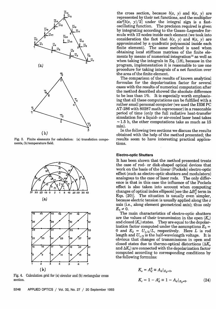
For the solution of the thermoelastic problem thecalculation grid is based on a subparametrical curvi-linear triangular (Lagrangian) finite element with 20degrees of freedom [Fig. 3(a)]. Such a finite elementcontains 10 nodes inside itself, 6 of them on itsboundary, where the temperature is defined; eachtranslation component is approximated by a fullthird-order polynomial, the temperature field and theborders, by second-order polynomials.
The temperature calculation grid is built on thebasis of an isoparametrical curvilinear triangular(Lagrangian) finite element with 6 degrees of freedom[Fig. 3(b)]. This means that the temperature fieldand the borders of the finite element are approxi-mated by full second-order polynomial. The samegrid is used for representation of aij, Bij. Shapefunctions for the finite elements in use are given inRef. 14. Examples of the calculation grid are shown:for a circular region, in Fig. 4(a) and for a rectangularregion, in Fig. 4(b). In these figures only the nodesfor the temperature field calculation are marked andnumbered.
Second, when one is calculating the depolarizationfactor Ad, it is especially important to choose properlythe numerical method of integrating over the area of
20 September 1993 / Vol. 32, No. 27 / APPLIED OPTICS 5247
B = AM + AB-�ii V zj )
U12
U2 U10
Us
(a)
I
\T3
(b)Fig. 3. Finite elements for calculation: (a) translation compo-nents, (b) temperature field.
37 30 23 16 9 2 1 8 45 22 29 36 43
(a)
the cross section, because 8(x, y) and (x, y) arerepresented by their net functions, and the multipliersin2[8(x, y)/ 2 ] under the integral sign is a fast-oscillating function. The precision required is givenby integrating according to the Gauss-Legendre for-mula with 12 nodes inside each element (we took intoconsideration the fact that 8(x, y) and (x, y) areapproximated by a quadratic polynomial inside eachfinite element). The same method is used whenobtaining local stiffness matrices of the finite ele-ments by means of numerical integrations as well aswhen taking the integrals in Eq. (18), because in theprogram, implementation it is reasonable to use oneprocedure for taking integrals of a net function overthe area of the finite element.
The comparison of the results of known analyticalformulas for the depolarization factor for severalcases with the results of numerical computation afterthe method described showed the absolute differenceto be less than 1%. It is especially worth emphasiz-ing that all these computations can be fulfilled with arather small personal computer (we used the IBM PCAT-286 with 80287 math coprocessor) in a reasonableperiod of time (only the full radiative heat-transfersimulation for a liquid- or air-cooled laser head takes
1.5 h, the other computations take as much as 15min).
In the following two sections we discuss the resultsobtained with the help of the method presented; theresults seem to have interesting practical applica-tions.
Electro-optic ShuttersIt has been shown that the method presented treatsthe case of rod- or disk-shaped optical devices thatwork on the basis of the linear (Pockels) electro-opticeffect (such as electro-optic shutters and modulators)analogous to the case of laser rods. The only differ-ence is that in this case the influence of the Pockelseffect is also taken into account when computingchanges of optical index ellipsoid [see the ABEJ term inEqs. (20)]. The situation is usually even simpler,because electric tension is usually applied along the zaxis (i.e., along element geometrical axis); thus onlyE3 0 .
The main characteristics of electro-optic shuttersare the values of their transmission in the open (K0 )and closed (KC) states. They are equal to the depolar-ization factor computed under the assumptions E3 =0 and E3 = U 2/L, respectively. Here L is rodlength and UX/ 2 is the half-wavelength voltage. It isobvious that changes of transmissions in open andclosed states due to thermo-optical distortions (AKand AK,) are connected with the depolarization factorcomputed according to corresponding conditions bythe following formulas:
( b)Fig. 4. Calculation grid for (a) circular and (b)section.
rectangular cross
K = A=Ad I E3=0
K = 1 -Ad-= 1 -AdIE3 CO.
5248 APPLIED OPTICS / Vol. 32, No. 27 / 20 September 1993
(24)
For KDP electro-optic shutters (and only for them),because irl 12 the values of AK& and AK, hardlydiffer3 4 ; for practical purposes AK = K AK =
AdIE3 = 0.
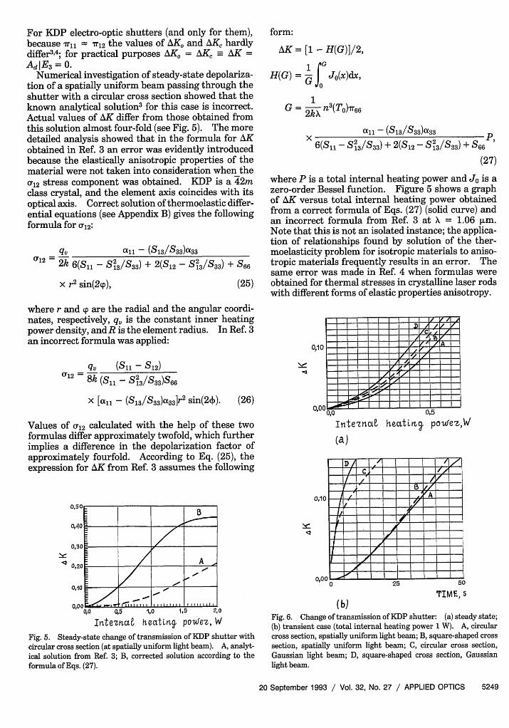
Numerical investigation of steady-state depolariza-tion of a spatially uniform beam passing through theshutter with a circular cross section showed that theknown analytical solution3 for this case is incorrect.Actual values of AK differ from those obtained fromthis solution almost four-fold (see Fig. 5). The moredetailed analysis showed that in the formula for AKobtained in Ref. 3 an error was evidently introducedbecause the elastically anisotropic properties of thematerial were not taken into consideration when thea12 stress component was obtained. KDP is a 42mclass crystal, and the element axis coincides with itsoptical axis. Correct solution of thermoelastic differ-ential equations (see Appendix B) gives the followingformula for Cu12:
q all - (S/S 3 3)a3 3
2 2k 6(Sl - S13 /S 3 3) + 2(S12 - S13 /S 33) + S6 6
x r2 sin(29), (25)
where r and p are the radial and the angular coordi-nates, respectively, q is the constant inner heatingpower density, and R is the element radius. In Ref. 3an incorrect formula was applied:
qu (S1 - S12)612 = 8k (S,1 - S23 /S33 )S66
x [a,, - (S 3 /S3 3)a 3 3 ]r2 sin(24). (26)
Values of cr12 calculated with the help of these twoformulas differ approximately twofold, which furtherimplies a difference in the depolarization factor ofapproximately fourfold. According to Eq. (25), theexpression for AK from Ref. 3 assumes the following
oq5 1,0 1,5 2,0
Irte-mta hectLm poufes, W
Fig. 5. Steady-state change of transmission of KDP shutter withcircular cross section (at spatially uniform light beam). A, analyt-ical solution from Ref. 3; B, corrected solution according to theformula of Eqs. (27).
form:
AK = [1 -H(G)]2,
H(G) = fG Jo(x)dx,
G 2k n3(TO)7r66
all - (S/S 3 3 )a3 3 P
6(Sl - S2 3 /S 3 3 ) + 2(SI2 - S23/S 3 3) + S6 6
(27)
where P is a total internal heating power and Jo is azero-order Bessel function. Figure 5 shows a graphof AK versus total internal heating power obtainedfrom a correct formula of Eqs. (27) (solid curve) andan incorrect formula from Ref. 3 at = 1.06 pum.Note that this is not an isolated instance; the applica-tion of relationships found by solution of the ther-moelasticity problem for isotropic materials to aniso-tropic materials frequently results in an error. Thesame error was made in Ref. 4 when formulas wereobtained for thermal stresses in crystalline laser rodswith different forms of elastic properties anisotropy.
0,10
= = = = == I I l // A
= = = = = I c<F) 1 I I I I _ _ tA I 1= I I = I =h I z
= =I_ I Z -----
I U,3ThtezrLQ heutinrs po-ufez,W
(a)
-A /---g-/- I -I 1-A/
_ c f _ I' I / /
0,10 /- ----
- I I I -__ IUn - Ie I I I= I ==_ C_ I = I I = I o _ I I I =j =I
0 25 50
TIME, S(b)
Fig. 6. Change of transmission of KDP shutter: (a) steady state;(b) transient case (total internal heating power 1 W). A, circularcross section, spatially uniform light beam; B, square-shaped crosssection, spatially uniform light beam; C, circular cross section,Gaussian light beam; D, square-shaped cross section, Gaussianlight beam.
20 September 1993 / Vol. 32, No. 27 / APPLIED OPTICS 5249
o.Uz
vast
Figures 6(a) and 6(b) show the results of numericalsimulations for shutters with circular- and square-shaped (with the sides of the square equal to thediameter of the circle) cross sections for spatiallyuniform and Gaussian beams. The intensity of theGaussian beam was considered to be
I(r) = Io exp(-2r2 /R2 ),
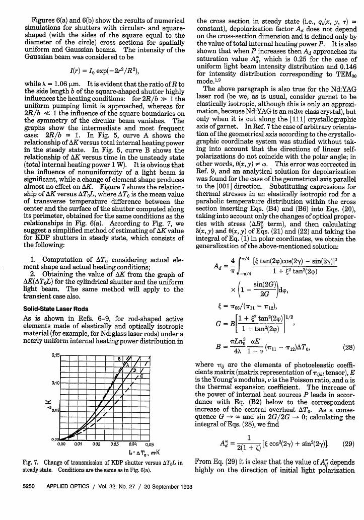
while X = 1.06 jum. It is evident that the ratio of R tothe side length b of the square-shaped shutter highlyinfluences the heating conditions: for 2R/b >> 1 theuniform pumping limit is approached, whereas for2R/b << 1 the influence of the square boundaries onthe symmetry of the circular beam vanishes. Thegraphs show the intermediate and most frequentcase: 2R/b = 1. In Fig. 5, curve A shows therelationship of AK versus total internal heating powerin the steady state. In Fig. 5, curve B shows therelationship of AK versus time in the unsteady state(total internal heating power 1 W). It is obvious thatthe influence of nonuniformity of a light beam issignificant, while a change of element shape producesalmost no effect on AK. Figure 7 shows the relation-ship of AK versus A TOL, where ATo is the mean valueof transverse temperature difference between thecenter and the surface of the shutter computed alongits perimeter, obtained for the same conditions as therelationships in Fig. 6(a). According to Fig. 7, wesuggest a simplified method of estimating of AK valuefor KDP shutters in steady state, which consists ofthe following:
1. Computation of ATo considering actual ele-ment shape and actual heating conditions;
2. Obtaining the value of AK from the graph ofAK(AToL) for the cylindrical shutter and the uniformlight beam. The same method will apply to thetransient case also.
Solid-State Laser RodsAs is shown in Refs. 6-9, for rod-shaped activeelements made of elastically and optically isotropicmaterial (for example, for Nd:glass laser rods) under anearly uniform internal heating power distribution in
0,00 0.01 0.02 0.03 Q04 o,05
L To, nK
Fig. 7. Change of transmission of KDP shutter versus ATOL insteady state. Conditions are the same as in Fig. 6(a).
the cross section in steady state (i.e., q(x, y, T) =constant), depolarization factor Ad does not dependon the cross-section dimension and is defined only bythe value of total internal heating power P. It is alsoshown that when P increases then Ad approaches itssaturation value A', which is 0.25 for the case ofuniform light beam intensity distribution and 0.146for intensity distribution corresponding to TEMoomode., 9
The above paragraph is also true for the Nd:YAGlaser rod (be we, as is usual, consider garnet to beelastically isotropic, although this is only an approxi-mation, because Nd:YAG is an m3m class crystal), butonly when it is cut along the [111] crystallographicaxis of garnet. In Ref. 7 the case of arbitrary orienta-tion of the geometrical axis according to the crystallo-graphic coordinate system was studied without tak-ing into account that the directions of linear self-polarizations do not coincide with the polar angle; inother words, 0(x, y) • p. This error was corrected inRef. 9, and an analytical solution for depolarizationwas found for the case of the geometrical axis parallelto the [001] direction. Substituting expressions forthermal stresses in an elastically isotropic rod for aparabolic temperature distribution within the crosssection inserting Eqs. (B4) and (B6) into Eqs. (20),taking into account only the changes of optical proper-ties with stress (ABW term), and then calculating8(x, y) and (x, y) of Eqs. (21) and (22) and taking theintegral of Eq. (1) in polar coordinates, we obtain thegeneralization of the above-mentioned solution:
4 j/4 [e tan(2(p)cos(2y) - sin(2y)]2
Ad-v /= 1 + 2 tan2 (2qp)
X - sin(2G))d,
= 'r66/(Tll-12)
[1 + 2 tan2(2q) 1/2
1 + tan2(2p)
XrLn3 1EB = 4?, °1 -_ (rll - M12)ATO, (28)
where rij are the elements of photoeleastic coeffi-cients matrix (matrix representation of Tijkl tensor), Eis the Young's modulus, v is the Poisson ratio, and a isthe thermal expansion coefficient. The increase ofthe power of internal heat sources P leads in accor-dance with Eq. (B2) below to the correspondentincrease of the central overheat ATO. As a conse-quence G - o and sin 2G/2G - 0; calculating theintegral of Eqs. (28), we find
A 2( + ) [ cos 2(2y) + sin2 (2y)]. (29)
From Eq. (29) it is clear that the value of A' dependshighly on the direction of initial light polarization
5250 APPLIED OPTICS / Vol. 32, No. 27 / 20 September 1993
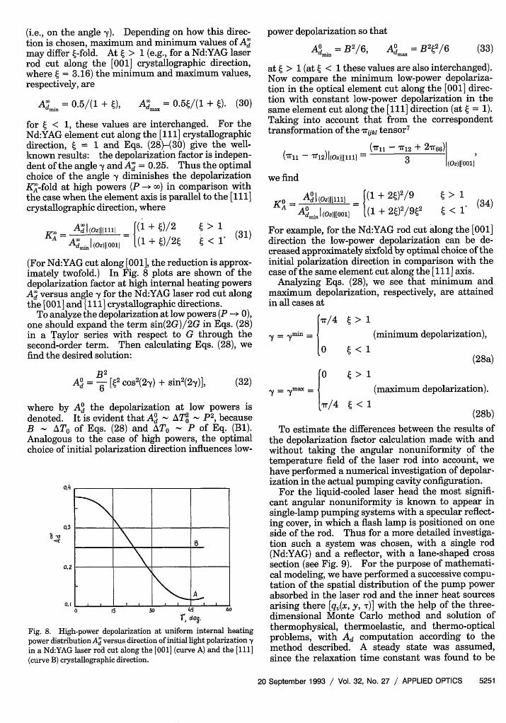
(i.e., on the angle y). Depending on how this direc-tion is chosen, maximum and minimum values of Admay differ t-fold. At > 1 (e.g., for a Nd:YAG laserrod cut along the [001] crystallographic direction,where e = 3.16) the minimum and maximum values,respectively, are
Admi = 0.5/(1 + I), Ad = 0.5e/(1 + I). (30)
for < 1, these values are interchanged. For theNd:YAG element cut along the [111] crystallographicdirection, = 1 and Eqs. (28)-(30) give the well-known results: the depolarization factor is indepen-dent of the angle y andA' = 0.25. Thus the optimalchoice of the angle y diminishes the depolarizationKA'-fold at high powers (P m o) in comparison withthe case when the element axis is parallel to the [111]crystallographic direction, where
power depolarization so that
Admin - AO =B 22/6 (33)
at > 1 (at < 1 these values are also interchanged).Now compare the minimum low-power depolariza-tion in the optical element cut along the [001] direc-tion with constant low-power depolarization in thesame element cut along the [111] direction (at g = 1).Taking into account that from the correspondenttransformation of the Trijkl tensor7
('r11 - '2)1(oz)jj[11] =(I11 - 7T12 + 21T66)
3 (oz)(j[oo1]
we find
K0- Ad (oZ)11[l _ |(1 + 2e)2/9
KAO Id | l(1 + 22/9t2Admi (Oz)jj[00] [,.L + 2 J '
(34)
A A I (Oz)I[001] 1(1 + g)/2E
> 1< 1-
(31)
(For Nd:YAG cut along [001], the reduction is approx-imately twofold.) In Fig. 8 plots are shown of thedepolarization factor at high internal heating powersAd versus angle y for the Nd:YAG laser rod cut alongthe [001] and [111] crystallographic directions.
To analyze the depolarization at low powers (P --. 0),one should expand the term sin(2G)/2G in Eqs. (28)in a Taylor series with respect to G through thesecond-order term. Then calculating Eqs. (28), wefind the desired solution:
B 2AO= - [2 cos 2(2y) + sin 2(2,y)],
d 6 (32)
where by Ad the depolarization at low powers isdenoted. It is evident that A A P2 , becauseB - ATo of Eqs. (28) and ATo P of Eq. (Bi).Analogous to the case of high powers, the optimalchoice of initial polarization direction influences low-
0,3
____ B
0.2
A
0 15 30 45 60
f, deo.
Fig. 8. High-power depolarization at uniform internal heatingpower distributionAd versus direction of initial light polarization yin a Nd:YAG laser rod cut along the [001] (curve A) and the [111](curve B) crystallographic direction.
For example, for the Nd:YAG rod cut along the [001]direction the low-power depolarization can be de-creased approximately sixfold by optimal choice of theinitial polarization direction in comparison with thecase of the same element cut along the [111] axis.
Analyzing Eqs. (28), we see that minimum andmaximum depolarization, respectively, are attainedin all cases at
I m /4
'Y= Ymn (minimum depolarization),
ly= y m
ax {(28a)
(maximum depolarization).
(28b)
To estimate the differences between the results ofthe depolarization factor calculation made with andwithout taking the angular nonuniformity of thetemperature field of the laser rod into account, wehave performed a numerical investigation of depolar-ization in the actual pumping cavity configuration.
For the liquid-cooled laser head the most signifi-cant angular nonuniformity is known to appear insingle-lamp pumping systems with a specular reflect-ing cover, in which a flash lamp is positioned on oneside of the rod. Thus for a more detailed investiga-tion such a system was chosen, with a single rod(Nd:YAG) and a reflector, with a lane-shaped crosssection (see Fig. 9). For the purpose of mathemati-cal modeling, we have performed a successive compu-tation of the spatial distribution of the pump powerabsorbed in the laser rod and the inner heat sourcesarising there [qv(x, y, T)] with the help of the three-dimensional Monte Carlo method and solution ofthermophysical, thermoelastic, and thermo-opticalproblems, with Ad computation according to themethod described. A steady state was assumed,since the relaxation time constant was found to be
20 September 1993 / Vol. 32, No. 27 / APPLIED OPTICS 5251
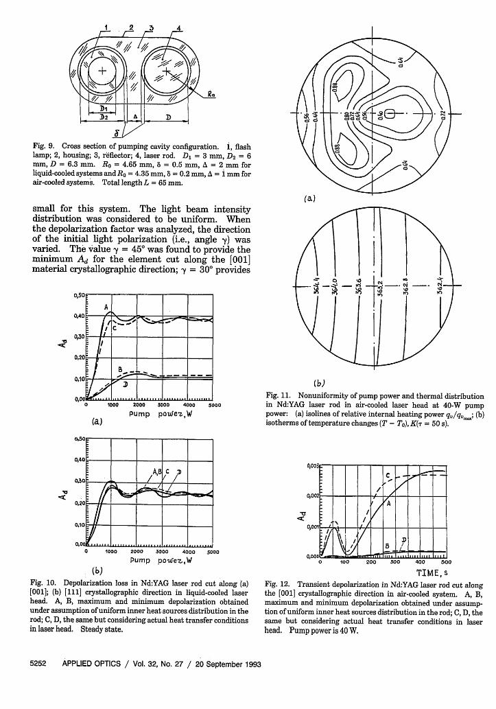
Fig. 9. Cross section of pumping cavity configuration. , flashlamp; 2, housing; 3, reflector; 4, laser rod. D = 3 mm, D2 = 6mm, D = 6.3 mm. Ro = 4.65 mm, 8 = 0.5 mm, A = 2 mm forliquid-cooled systems and Ro = 4.35 mm, 8 = 0.2 mm, A = i mm forair-cooled systems. Total length L = 65 mm.
small for this system. The light beam intensitydistribution was considered to be uniform. Whenthe depolarization factor was analyzed, the directionof the initial light polarization (i.e., angle y) wasvaried. The value y = 450 was found to provide theminimum Ad for the element cut along the [001]material crystallographic direction; y = 30° provides
-a
(a)Pump poxe'z.,W
2000 3000 4000 5000
Pump poIuez,W
. (b)Fig. 10. Depolarization loss in Nd:YAG laser rod cut along (a)[001]; (b) [111] crystallographic direction in liquid-cooled laserhead. A, B maximum and minimum depolarization obtainedunder assumption of uniform inner heat sources distribution in therod; C, D, the same but considering actual heat transfer conditionsin laser head. Steady state.
(b)Fig. 11. Nonuniformity of pump power and thermal distributionin Nd:YAG laser rod in air-cooled laser head at 40-W pumppower: (a) isolines of relative internal heating power qv/qvm; (b)isotherms of temperature changes (T - To), K( = 50 s).
TIME, sFig. 12. Transient depolarization in Nd:YAG laser rod cut alongthe [001] crystallographic direction in air-cooled system. A, B,maximum and minimum depolarization obtained under assump-tion of uniform inner heat sources distribution in the rod; C, D, thesame but considering actual heat transfer conditions in laserhead. Pump power is 40 W.
5252 APPLIED OPTICS / Vol. 32, No. 27 / 20 September 1993
(a)
0100
0 -
AB C IMO - I__ / I/ / I
// 1% '-.' 0 ft'; i �0,20
0110
0,00 1000

the minimum Ad for the element cut along the [111]direction, while y = 00 provides the maximum in bothcases. In Fig. 10(a), two pairs of curves for theminimum and the maximum depolarization factorsversus the pump power are given for the case whenthe element axis coincides with the [001] crystallo-graphic direction. In each pair one curve representsthe results obtained with a nonuniform internalheating power distribution by the Monte Carlo meth-od; the other curve represents the same resultsobtained with a uniform internal heating powerdistribution and the same integral heating powervalue P. It is obvious that the difference is rathersmall for practical purposes. Figure 10(b) showscurves for the case with the element axis parallel tothe [111] direction (the graphs for the minimum andthe maximum depolarization factors for uniforminternal heating power coincide in this case; thusthere are only three curves). The results still differmuch less. (Results could differ slightly more forNd:glass laser rods because of their small thermalconductivity.) The main conclusion is that for esti-mating the value of depolarization for the Nd:YAGlaser rod the assumption of a uniform internal heat-ing power distribution is appropriate.
For investigation of depolarization in air-cooledpumping systems the same pumping system has beenused but with corresponding reduction of inner chan-nels and flash lamp diameters. In this case the mostimportant thing is the thermo-optical behavior of thelaser rod in an unsteady state. In Fig. 11 isolines ofthe relative internal heating power in the laser rodqv/qv~m along with the isotherms of temperaturechanges (T - To) at 40-W pump power, 50 s afterswitching on, are shown. Plots of the minimum andthe maximum depolarization factors versus time forthis system are shown in Fig. 12. The element axiscoincides with the [001] crystallographic direction.(In the case when it coincides with the [111] direction,the depolarization factor is negligibly small.) As isshown in the graph, maximum values of the depolar-ization factor obtained with and without the uniforminternal heating power assumption differ consider-ably from each other. (Never mind that Ad is smallitself; it is so because of the small pump power.) It isalso important that the dependence on time, Ad, isnonmonotonic. The maximum value of the depolar-ization factor may differ considerably from the samevalue in a steady state. (Much greater differencemay occur in case of Nd:glass active medium.)Analysis of depolarization in such systems may bemade only by means of the numerical method pre-sented.
ConclusionsWe present the results of numerical investigation ofthermo-optical distortions in KDP electro-optic shut-ters and Nd:YAG laser rods. It seems also to beimportant to carry out further analogous investiga-
tions according to the numerical method describedfor laser rods and shutters made of other crystallinematerials, acousto-optic modulators, and crystals forsecond-harmonic generation.
Appendix A. Derivation of Matrix-Form Hooke Law forPlane Anisotropic Thermoelastic Problem
Consider the three-dimensional anisotropic form ofHooke's law 7:
T11
c22
cr3 3
Cr23
c1 3
0'12
Cl
C21
C31
C41
C51
-C61
C12 C13 C14 C15
C22 C23 C24 C25
C32 C33 C34 C35
C42 C43 C44 C45
C52 C53 C54 C55
C6 2 C63 C64 C65
C16
C26
C36
C46
C56
C66
Ell - all(T - To)
E22 - a22(T - To)
33 - a33(T - To)X 2 E2 3 - 2 3 (T- To)
2 E13 - al3(T - To)
E12 - al2(T - To)
(Al)
The equivalent form of presentation is
Ell - all(T- T0)
E22 - a22(T- To)
E33 - U-3 3 (T - To)
2E23 - U-23 (T - To)
2E13 - Ua(T - To)
2E12 - ccl2(T - To)
Sl
S2 1
S31
S41
S 5 1
S61
S12 S13
S2 2 S23
S3 2 S33
S4 2 S4 3
S5 2 S5 3
S62 S6 3
S1 4
S24
S34
S44
S54
S64
S1 5
S2 5
S3 5
S 4 5
S 5 5
S 6 5
S16
S2 6
S3 6
S4 6
S56
S66 -
all
aO22
U3 3
U2 3
cr13
al 2
(A2)
Here Sij are the components of strain-stress matrix(matrix representation of Sijkl strain-stress tensor),
bare components of stress-strain matrix ( 11 Sij 11=11 Ci 1), aij are components of thermal expansion
tensor. Their values in crystallographic coordinatesystem for crystals with different symmetry classesare given in Ref. 17.
In the case of plane stress, 6 1 3 = Cr2 3 = a3 3 = 0 is
assumed. Substituting this into Eq. (Al) and bear-
20 September 1993 / Vol. 32, No. 27 / APPLIED OPTICS 5253
ingin mind Eq. (13), we obtain
/ a1,
{&} = a-2 2 ,
°X12
[CH1
[D] = C21
_C61
C12
C22
C62
C16 1 C13
C26 - C23
C66 j C63
[C33 C3 4 C3 5 -' [C 3 1
X C4 3 C4 4 C4 5 C4 1
[C5 3 C5 4 C5 5 I C5 ,
In the case of plane strain e13assumed. Substituting this intoing the resulting equations withand 0-33 , we find
C14 C15
C24 C25
C64 C65 JC3 2
C4 2
C5 2
C3 6 1C46 .IC5 6 -
Appendix B. Derivation of Formulas for ThermalStresses in Cylindrical Anisotropic Optical Elements atUniform Heating
(A3) The method of analytical solution of anisotropicthermoelastic problem in long rods with parabolictemperature distribution was given in Ref. 18, whereit was applied to cubic crystals. Here we apply thesame method to obtain analytical expression forthermal stresses in a 42m class crystalline rod.
In a long rod with a circular cross section underconditions of uniform heat evolution and dissipationq = P/7rR2L = constant, where P is a total internal
(A4) heating power, and R and L are the radius and lengthof the rod, respectively. The temperature field isparabolic:
= E23 = E33 = 0 is
Eq. (A2) and solv-respect to U`3 , 23 ,
T(r) = Ta + ATO(1 -
ATo = qfR2/4k = P/4rkL,( 3 3
01 3 =
02 3
S3 4 35 -1
S4 4 S45
S5 4 S55
U33
X 13 (T- T) +_ U23
Substituting Eq. (AS) into Eq. (A2)bearing in mind Eq. (13), we obtain
-S31 S32 S36- O'f11
S41 S4 2 S4 6 0o22
S51 S52 S56 JU12 -
(A5)
once again and
fa1 [S13 S1 4S 15
{Ij} = a22 - S23 S2 4 S25
aX12 LS63 S64 S65J
S3 3 S3 4
X S43 S4 4
[S5 3 S5 4
S35 -I tX33
S4 5 aL23 ,
S J\ aU13
(A6)
(B1)
where Ta is the temperature of the boundary mediumand r = X2 + y2 is the radial coordinate. It is simplerto solve the thermoelastic problem analytically byusing St. Venant's equation for strains' 7 instead ofEqs. (14) in the system of plain thermoelastic differen-tial Eqs. (12)-(14):
a2ell a222 a2E12
axl +--x2 aa(B2)
For a rod made of 42m material, when the crystal-lographic coordinates coincide with the geometricalones, Si, = S22, S44 = S5 5, S13 = S1 2, and S14 S5 =S1 6 = S2 4 = S2 5 = S2 6 = S3 4 = S35 = S3 6 = S4 5 = S4 6 =S56 = 0. Also in this case a = a-2 2 and aL12 = Ca13 =a 23 = 0.17 Taking this into account and conse-quently substituting Eqs. (A6) and (A7) into Eq. (13)and the result into Eq. (B2), we find the followingequation:
(511 -S2 ,20,1 a2c 22)3 x 3 + ox2
Sll I
[D]= S21 I
_S6 1
[S33
X S43
[S53
S' 2
S22
362
S34
S44
S54
S16 S13
S26 - S23
S66 J [S63
S14
S24
S6 4
S15
S25
S651
S351-[S31 S3 2 S36-
S4 5 S4 1 S4 2 S4 6
S55 LS51 S5 2 S5 6 J
+ (s 12
+ (t,
(A7)
One should emphasize that when the geometricalcoordinate system of the element does not coincidewith material crystallographic one, the Sijkl and Cijkltensors (and not Sij and Cj matrices) should betransformed according to the formulas given in Ref.17.
S3'1( a2gl
S33/k a2
+ dAc22M
dx1
- S1 3 IV2 a2U12-- 3 3 I 33 T = S66 alX (B3)
Here V2 is a Laplacian. Seeking the solutions of Eq.(B3) in the form that automatically satisfies equilib-rium Eqs. (12) and the boundary conditions of Eqs.(15),
c`1 = max (1 - X2
- 3y2)/2
U22 = Jmax(1 - 3X2- y2)/2,
12 = (maxX (B4)
5254 APPLIED OPTICS / Vol. 32, No. 27 / 20 September 1993
S33
- S43
_S53
4
4
where uml, = constant, and using Eq. (Bi), from Eq.(B3) we can obtain
q a11 -(S13/S33)33
umax k 2(i _ S2 / 2 C6(S,- S13/S33) + 2(S12 -S 3 /S 33) + S66
(B5)
For an elastically isotropic rod S,, = S2 2 = S33 =
1/E, S44 = S55 = S66 = 2(1 + v)/E, S12 = S13 = S2 3 =
-v/E, S14 = S15 = S16 = S2 4 = S25 = S26 = S3 4 = S3 5 =
S3 6 = S45 = S4 6 = S56 = 0, aY1 = 22 = at33 - a,a-12 = a13 = at23 = 0, where E - Young's modulus, v isthe Poisson ratio, at is the isotropic thermal expansioncoefficient.' 7 All of the above mentioned is alsocorrect for an elastically isotropic rod, and from Eq.(B3) a well-known formula can be found;
qu 81E" max 8k 1- v (B6)
This method can be applied to yield the thermal stressdistribution in long rods made of crystals with differ-ent types of symmetry, but only for a parabolictemperature field within the cross section.
References1. W. Koechner, Solid State Laser Engineering (Springer-Verlag,
New York, 1976).2. N. Gopi, T. P. S. Nathan, and B. K. Sinha, "Experimental
studies of transient, thermal depolarization in a Nd:glass laserrod," Appl. Opt. 29, 2259-2265 (1990).
3. J. F. Nye, Physical Properties of Crystals (Clarendon, Oxford,1964).
4. I. P. Kaminow, "Strain effects in electrooptical light modula-tors," Appl. Opt. 3, 511-515 (1964).
5. D. Eimerl, "High average power harmonic generator," IEEEJ. Quantum Electron. QE-23, 525-592 (1987).
6. E. K. Malbutis, J. J. Reksnys, and S. V. Sakalauskas, "Contri-bution of thermoeleastic stresses into dn/dT for crystals ofhexagonal and trigonal symmetry heated by laser radiation,"Kvantovaya Elektron. (Moscow) 2, 2493-2498 (1975).
7. W. Koechner and D. K. Rice, "Effect of birefringence on theperformance of linearly polarized Nd:YAG lasers," IEEE J.Quantum Electron. QE-7, 557-566 (1970).
8. M. A. Karr, "Nd:YAG laser due to internal Brewster polariz-er," Appl. Opt. 10, 893-895 (1971).
9. W. Koechner, "Transient thermal profile in optically pumpedlaser rods," J. Appl. Phys. 44, 3162-3170 (1973).
10. L. N. Soms, A. A. Tarasov, and V. V. Shashkin, "On theproblem of linearly polarized light by YAG:Nd3+ laser rodunder conditions of thermally induced birefringence," Kvan-tovaya Elektron. (Moscow) 7, 619-620 (1980).
11. G. N. Dulnev, A. E. Michailov, and V. G. Parfenov, "Themodeling of the thermal regimes of the pump systems," J.Eng. Phys. Engl. Transl. 53, 107-113 (1987).
12. D. Skinner and I. Tregellas-Williams, "Total energy andenergy distribution in a laser crystal due to optical pumping, ascalculated by Monte-Carlo method," Aust. J. Phys. 19, 7-17(1966).
13. A. V. Lykov, Heat-Mass Transfer (Energiya, Moscow, 1972).14. R. Siegel and J. R. Howell, Thermal Radiation Heat Transfer
(McGraw-Hill, New York, 1972).15. 0. C. Zienkiewicz, The Finite Element Method in Engineering
Science (McGraw-Hill, New York, 1977).16. D. H. Anderson, J. C. Tannenhill, and R. H. Pletcher, Compu-
tational Mechanics and Heat Transfer (Hemisphere, NewYork, 1984), Vol. 1.
17. S. P. Timoshenko and J. N. Goodier, Theory of Elasticity, 3rded. (McGraw-Hill, New York, 1970).
18. B. N. Grechushnikova and D. Brodovskiy, "Thermal stressesin cubic crystals," Kristallographiya 1, 597-599 (1956).
20 September 1993 / Vol. 32, No. 27 / APPLIED OPTICS 5255