numerical investigation of the homogeneous strain assumption for wood fibre composite materials
TRANSCRIPT

Master’s DissertationStructural
Mechanics
KRISTIAN STÅLNE and
PER JOHAN GUSTAFSSON
NUMERICAL INVESTIGATION OFTHE HOMOGENEOUS STRAINASSUMPTION FOR WOODFIBRE COMPOSITE MATERIALS

Denna sida skall vara tom!
Copyright © 2008 by Structural Mechanics, LTH, Sweden.Printed by KFS i Lund AB, Lund, Sweden, November 2008.
For information, address:
Division of Structural Mechanics, LTH, Lund University, Box 118, SE-221 00 Lund, Sweden.Homepage: http://www.byggmek.lth.se
Structural MechanicsDepartment of Construction Sciences
ISRN LUTVDG/TVSM--08/7157--SE (1-15)ISSN 0281-6679
NUMERICAL INVESTIGATION OF
THE HOMOGENEOUS STRAIN
ASSUMPTION FOR WOOD
FIBRE COMPOSITE MATERIALS
KRISTIAN STÅLNE andPER JOHAN GUSTAFSSON

Denna sida skall vara tom!

1
NUMERICAL INVESTIGATION OF THE HOMOGENEOUS STRAIN
ASSUMPTION FOR WOOD FIBRE COMPOSITE MATERIALS
Kristian Stålne,
Prof. Per Johan Gustafsson
Division of Structural Mechanics
Lund University
P.O. Box 118, SE-221 00 Lund
Abstract
The stiffness and hygroexpansion properties of a wood fibre composite material was calculated by
means of finite element analysis based homogenisation. The purpose was to investigate if the often
used assumption of homogeneous strain is valid when analysing paper based composite materials.
The representative volume element, the RVE, consists of in-plane randomly oriented orthotropic
fibres, fibre crossings and an isotropic matrix material in the complementary area. The RVE was
subjected to cyclic boundary conditions and plane stress. For a fibre volume fraction of 60 percent,
which is typical for paper based composite products, the assumption of homogeneous strain was
found to overestimate the composite stiffness by approximately 15 percent and underestimate the
hygroexpansion by approximately 15 percent as compared to the results of the numerical
simulations. These deviations produced by the homogeneous strain assumption can be considered to
be within an acceptable range of engineering accuracy for analytical models for simplified analysis
of stiffness and hygroexpansion properties of paper based composite materials.
Introduction
High pressure laminate, HPL, is a wood fibre composite composed of craft paper impregnated by
phenolic or melamine resin. An important issue concerning wood composites is that of shape
stability in relation to moisture content gradients and changes [1]. This entails a need for models
that enable analysis and prediction of the hygroexpansion and stiffness properties of wood fibre
composites such as HLP.
Various analytical models for analysis of the stiffness properties of fibre composite materials have
been developed in recent decades [2]. A common approach is to model the composite as a single

2
fibre surrounded by matrix material [3,4,5]. These models assumes there to be no interaction
between the fibres. Such an assumption is, however, questionable in connection with HPL since the
particle phase of this composite material is paper, which is a network of long fibres that are bonded
to each other. Another approach that strongly simplifies calculations and may be relevant for HPL
composites is to assume homogeneous strain. Such a simplification makes it possible to model also
the complex material behaviour of the wood fibres, taking into account creep and mechano-sorptive
strains [6]. It has been shown, however, that the homogeneous strain assumption will always
overestimate the stiffness of a composite material [7,8]. The aim of this investigation is partly to
find out if this overestimation is sufficiently small for the assumption to be acceptable in modelling.
In the investigation is moreover the homogeneous strain based prediction of hygroexpansion
properties studied.
Developments in the area of numerical simulations by the finite element method have made it
possible to model complicated fibre composite material structures, consisting of more than one fibre
[9,10,11]. Most of these studies have dealt with estimation of the stiffness properties of plane fabric
composites [12,13,14,15,16]. These materials have a weaved fibre phase in which the fibres are
crossed over and under each other at right angles. Since the fabric geometry is regular,
homogenisation of a single fibre crossing is sufficient to provide a satisfactory estimate of the
composite material stiffness. Fibre networks of a more random type have also been studied using
numerical simulations [17,18]. There has been no study at a micro mechanical level, however, of
the behaviour of network composite materials of irregular geometry. It seems that numerical
simulations of hygroexpansion properties of composite materials with an irregular material structure
are lacking.
The present investigation is performed by comparing the results from a homogenisation performed
under the assumption of homogeneous strain and a numerical homogenisation of the same
representative volume element (RVE), a unit cell. The unit cell is a representation of a wood fibre
composite with an irregular fibre network, such that of paper. The parameters of the model are the
mechanical properties of the constituents, the fibre geometry, the fibre orientation distribution and
the fibre volume fraction. The configuration of the fibre network, number and orientation of the
fibres, and is created by a Monte Carlo simulation process. This enables a good representation of
the micro-structure of the fibre composite material.
The numerical results on stiffness and hygroexpansion are presented for a wide range of fibre
volume fractions. The results are compared to those obtained but the homogeneous strain

3
assumption and also to those obtained by the homogeneous stress assumption. To determine a
sufficient size of the RVE, calculations were made for a range of ratios between fibre width and unit
cell side length. To determine how fine the finite element mesh needs to be for good numerical
accuracy, calculation were made for a range of ratios between size of the finite elements and size of
the RVE. The numerical results versus the corresponding results of the homogeneous strain
assumption made it possible to make an estimation of the validity of that later assumption when
used in modelling of deformations of HPL materials as affected by stress, moisture, moisture
changes and time of loading.
The Numerical Model
Figure 1 shows an example of an RVE. In this example there are 5 fibres in the RVE and the RVE is
modelled by 30x30 finite elements. The RVE is a square with unit a constant thickness and the
finite elements are plane stress square shaped elements of equal size and of the Melosh type with 4
nods. The fibre material is modelled as orthotropic linear elastic and the matrix material as isotropic
linear elastic. Also the hygroexpansion properties of the fibres and the matrix are assumed to be
orthotropic and isotropic, respectively. The geometry and location of a fibre is defined by pre-
defined constant width and randomly selected orientation and location in the RVE. A finite element
is assigned the properties of a fibre if more than 50 percent of its volume is within a fibre, and vice
versa. In areas of fibre crossings are the finite elements assigned the average stiffness properties of
the crossing fibres. Cyclic boundary conditions are employed. This means that the RVE acts as
being surrounded by similar RVE:s and assumed to be a small part of an infinitely large volume of
composite material. Estimations of material properties of the cellulose fibre and melamine resin are
from [19] and [20] and is presented in Table 2 and Table 3, respectively.
The stiffness and hygroexpansion properties of the composite are evaluated by exposing the square
unit cell to 4 different loadings: global tensile strain in the x-direction, global tensile strain in the y-
direction, global shear strain in the x-y plane and increase in moisture content in the fibres and the
matrix. The response of the unit cell to these loads is obtained by solving the finite element system
of equations. The stiffness tensor of the unit composite cell is the calculated from the mean strains
and the boundary traction vectors and the hygroexpansion parameters of the composite cell are
obtained from the average strains in the x- and y-directions when exposing the cell to increased
moisture.
The model was implemented in Matlab-code [21], using the free-ware finite element toolbox
CALFEM [22] for the definition of the elements and the material properties and for assembling and

4
solving of the equation system. Evaluation of the composite material properties was then made by
means of Matlab.
Table 1: Model parameters
Side length of RVE (mm) = lx = ly 10 mm
Number of elements/side 20, 30, 50, 75, 100, 150
Fibre width / side length 0.02, 0.04, 0.05, 0.06, 0.08, 0.1,
0.125, 0.15, 0.2, 0.25, 0.3, 0.4
Number of fibres/RVE Randomly from 1 to 20
Table 2: Fibre material parameters in local coordinates, x being the longitudinal direction of the
fibre, y and z being the transverse directions, respectively:
Ex (GPa) 40 xy (-) 0.2 Gxy (GPa) 4 x (-) 0.0110-2
Ey (GPa) 5 xz (-) 0.2 Gxz (GPa) 4 y (-) 0.2610-2
Ez (GPa) 5 yz (-) 0.3 Gyz (GPa) 2 z (-) 0.2610-2
Table 3: Matrix material parameters:
E (GPa) 5.75
(-) 0.3
(-) 0.0110-2

5
Figure 1: A square unit cell with physical dimensions 10 x 10 mm, with 30x30 elements and 5 fibres
with a width relative to unit cell side length of 0.1.
Choice of modelling parameters
A sufficient size of the RVE and a sufficiently fine finite element mesh are needed for representative
and accurate numerical results. These modelling parameters were therefore studied before
investigating the homogeneous strain assumption.
Figure 2 shows the calculated normalized stiffnesses in the x- and y-directions as a function of the
number of finite elements, n, along a side of the RVE. The number of degrees of freedom is 2n2 and
calculations were made for n = 20 to n = 150. Simulations with three different fibre configurations
showed an accuracy better than 1 percent for n ≥ 50 for all three different fibre configurations, both
in the x- and y-directions. n = 50, corresponding to 2500 elements and 5000 degrees of freedom was
estimated to be sufficiently large and was thus used throughout in the subsequent calculations.
6
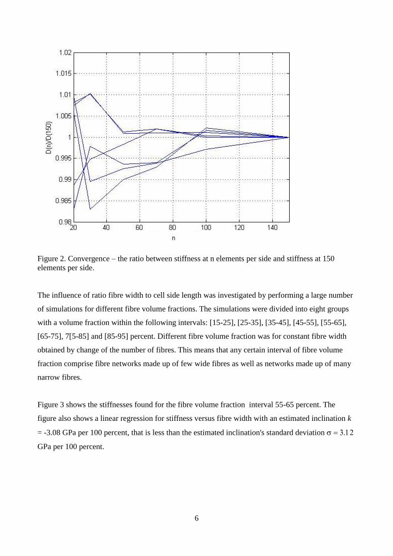
Figure 2. Convergence – the ratio between stiffness at n elements per side and stiffness at 150
elements per side.
The influence of ratio fibre width to cell side length was investigated by performing a large number
of simulations for different fibre volume fractions. The simulations were divided into eight groups
with a volume fraction within the following intervals: [15-25], [25-35], [35-45], [45-55], [55-65],
[65-75], 7[5-85] and [85-95] percent. Different fibre volume fraction was for constant fibre width
obtained by change of the number of fibres. This means that any certain interval of fibre volume
fraction comprise fibre networks made up of few wide fibres as well as networks made up of many
narrow fibres.
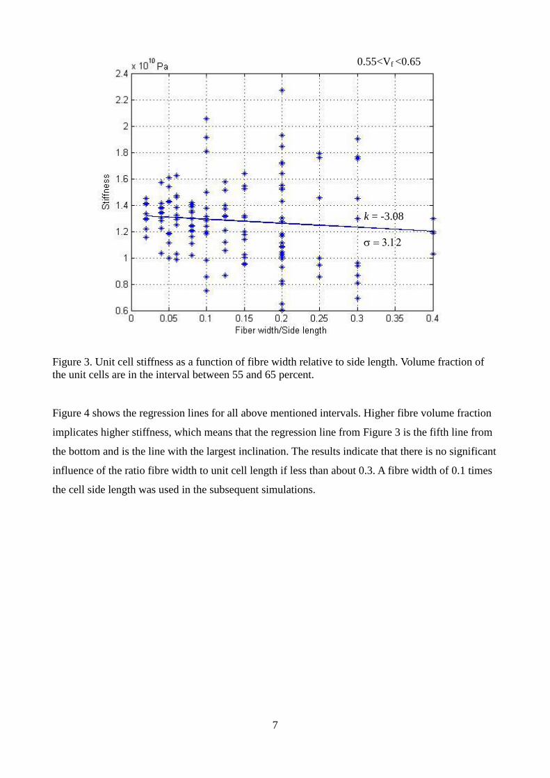
Figure 3 shows the stiffnesses found for the fibre volume fraction interval 55-65 percent. The
figure also shows a linear regression for stiffness versus fibre width with an estimated inclination k
= -3.08 GPa per 100 percent, that is less than the estimated inclination's standard deviation
GPa per 100 percent.
7
Figure 3. Unit cell stiffness as a function of fibre width relative to side length. Volume fraction of
the unit cells are in the interval between 55 and 65 percent.
Figure 4 shows the regression lines for all above mentioned intervals. Higher fibre volume fraction
implicates higher stiffness, which means that the regression line from Figure 3 is the fifth line from
the bottom and is the line with the largest inclination. The results indicate that there is no significant
influence of the ratio fibre width to unit cell length if less than about 0.3. A fibre width of 0.1 times
the cell side length was used in the subsequent simulations.
0.55<Vf <0.65
k = -3.08

8
Figure 4. Unit cell stiffness as a function of fibre width relative to side length. All intervals of
volume fractions, from bottom and up: 15-25 percent, 25-35 percent up to 85-95 percent.
Results
For investigation of the homogeneous strain and stress assumptions was 100 unit cells generated
with a random number of fibres in the range from 1 to 20, oriented and located at random. The
stiffness and moisture expansion properties of these cells were determined as described in the above
and then, for each individual unit cell, compared to the corresponding results as produced by the
homogeneous strain and homogeneous stress assumptions. The homogeneous strain composite
material stiffness was calculated as the average material stiffness matrix of the 2500 finite elements
and homogeneous stress stiffness was calculated as the inverse of the average compliance matrix for
the finite elements. The homogeneous strain and stress composite material moisture expansion
properties were calculated in the corresponding manner. The stiffness results are shown in Figure 5
where the 2x3x100=600 stiffnesses are plotted as a function of fibre volume fraction. The upper and
lower bounds of the stiffness are for each fibre cell configuration given by homogeneous strain and
stress assumptions. In figure 6 is the ratio between the homogeneous strain stiffness and the
numerically simulated stiffness shown for the 2x100 stiffness values. This ratio is, as expected, for
both directions and for all unit cells greater or equal to 1.0.

9
Figure 5. Homogenised stiffness in Pa in x- and y-directions according to: × – homogeneous strain,
• – finite element simulation, + – homogeneous stress assumption.

10
Figure 6. Relative stiffness = stiffness according to homogeneous strain divided by simulated
stiffness for each simulated unit cell with a regression line according to least square method.
The free hygroexpansion results are shown i Figure 7. Here the homogeneous strain and stress
assumptions are no longer giving bounds for the material properties as is the case of stiffness. This
is evident in Figure 8, showing the hygroexpansion of the homogeneous strain assumption divided
by the hygroexpansion of the simulations. For fibre volume fractions less than about 0.3 is the
hygroexpansion ratio greater than 1, and for Vf greater than about 0.3 less than 1.

11
Figure 7. Homogenised hygroexpansion in x- and y-directions according to: x – homogeneous
strain, · – finite element simulation, + – homogeneous stress assumption.
Figure 8. Relative hygroexpansion = hygroexpansion according to homogeneous strain divided by
simulated hygroexpansion, with a regression line, calculated according to least square method.

12
Conclusion
This paper presents a homogenisation of a wood fibre network composite material. The
homogenisation was performed using finite element analysis and cyclic boundary conditions and
the aim of the analysis was to investigate if the assumption of homogeneous strain is valid for
estimating stiffness and hygroexpansion of wood fibre composite materials with an in-plane random
fibre orientation distribution.
First modelling parameters in terms required size and required finite element mesh of the RVE were
determined. An RVE with a side length 10 times the fibre width and represented by a uniform finite
element mesh with 50x50 elements were found to be sufficient. In the subsequent analysis were 100
RVE:s with various fibre volume fraction and with random orientation and location of the fibres
analysed with respect to stiffness and hygroexpansion.
The results from the homogenisations show that the homogeneous strain assumption overestimates
the simulated stiffness by approximately 15 percent and underestimates the simulated
hygroexpansion by approximately 15 percent at the most interesting fibre volume fraction, which is
around 60 percent. The deviation of the results of the homogeneous strain assumption from the
results of the simulations is not greater than it can be justified to use the assumptions in analytical
modelling of HPL materials. There is also a possibility to introduce a correction factor to an
analytical model to take the deviation into account.
Acknowledgements
This work was financed by the Swedish Wood Technology Research Colleague, which is gratefully
acknowledged. The authors would also like to thank the Structural Mechanics division for support
and helpful discussions.
13
References
[1] Stålne K. Modelling of Stiffness and Hygroexpansion of Wood Fibre Composites. Licentiate
Thesis. 2001. Div of Structural Mechanics, Lund University.
[2] Hashin Z. Analysis of Composite Materials – A survey. J Appl Mech 1983;50:481-505.
[3] Eshelby JD. The Determination of the Field of an Elliptical Inclusion and Related Problems.
Proceedings of the Royal Society. London. 1957;A(241):376-396.
[4] Mori T, Tanaka K. Average Stress in Matrix and Average Elastic Energy of Materials with
Misfitting Inclusions. Acta Metallurgica 1973;21:571-574.
[5] Stålne K, Gustafsson PJ. A 3D Model for Analysis of Stiffness and Hygroexpansion Properties
of Fibre Composite Materials. J Eng Mat 2002;128(6):654-662.
[6] Stålne K. 3D Homogenisation of Hygroscopic Anisotropic Fibre Network Composite. Report
TVSM-7156, Div. of Structural Mechanics, Lund University, Sweden.
[7] Aboudi J. Mechanics of Composite Materials. Elsevier: Amsterdam, The Nederlands, 1991.
[8] Hill R. Elastic Behaviour of a Crystalline Aggregate. Proceedings of the Physical Society,
1951;Section A:349-354.
[9] Christman T, Needleman A, Suresh S. On Microstructural Evolution and Micromechanical
Modelling of Deformation of a Whisker-reinforced Metal-Matrix Composite. Mat Sci Eng
1989;A107:49-61.
[10] Baldwin JD, Altan MC, Rajamani K. Structural Analysis of an Injection Molded Short-Fiber-
Reinforced Disc. J of Mat Proc and Manu Sci. 1997;6:123-145.
[11] Ghassemieh E, Nassehi V. Stiffness Analysis of Polymeric Composites Using the Finite
Element Method. Adv in Pol Tech. 2001;20:42-57.
[12] Dasgupta A, Agarwal RK, Bhandarkar SM. Three-Dimensional Modeling of Woven-Fabric
Composites for Effective Thermo-Mechanical and Thermal Properties. Comp Sci Tech
1996;56:209-223.
[13] Thom H. Finite Element Modelling of Plain Weave Composites. J Comp Mat 1999;33:1491-
1510.
[14] Falzon PJ, Herszberg I. Effects of Compaction on the Stiffness of Plain Weave Fabric RTM
Composites. J Comp Mat 1996;30:1210-1247.
[15] Whithcomb JD, Chapman CD, Tang X. Derivation of Boundary Conditions for
Micromechanics Analysis of Plain and Satin Weave Composites. J Comp Mat 2000;34:724-747.
[16] Ishmar H, Schroter F, Streicher F. Modeling and Numerical Simulation of the Mechanical
Behaviour of Woven SiC/SiC regarding a Three Dimensional Unit Cell. Computational Mat Sci
2000;19:320-328.
[17] Nilsen N, Niskanen K. A 3D Simulation Model for Paper Structure. Progress in Paper Physics
– A Seminar Proceedings. 1996.
[18] Stahl DC, Cramer SM. A Three-Dimensional Network Model for a Low Density Fibrous
Composite. J Eng Mat Tech 1998;120:126-130.
[19] Person K. Micromechanical Modelling of Wood and Fibre Properties. Doctoral Thesis 2001.
Div of Structural Mechanics, Lund University.
[20] Hagstrand PO. Mechanical Analysis of Melamine-Formaldehyde Composites. Doctoral Thesis
1999. Chalmers University of Technology.
[21] Matlab 7.4. R2007a. The Math Works Inc., Natick, Ma, USA.
[22] CALFEM – A Finite Element Toolbox to MATLAB. Version 3.3. TVSM-9001.