numerical assessment of stimulation of geothermal wells ... · numerical assessment of hydraulic...
TRANSCRIPT

PROCEEDINGS, 43rd Workshop on Geothermal Reservoir Engineering
Stanford University, Stanford, California, February 12-14, 2018
SGP-TR-213
1
Numerical Assessment of Hydraulic Fracturing Stimulation Treatment of Geothermal Wells
Francesco Pizzocolo, Jan H. ter Heege and Peter A. Fokker
High Tech Campus 25, 5656 AE, Eindhoven (the Netherlands)
Keywords: Stimulation Technique, Treatment, Hydraulic Fracturing, Coupled Numerical Model, Hydroshearing, Acidizing,
Geothermal Well.
ABSTRACT
After years of exploiting steam, geothermal wells may need stimulation to remain economically profitable. Hydraulic fracturing can be a
suitable technique to improve steam production or to create new geothermal pay zones. The goal is to stimulate the area around the well
by connecting pre-existing fractures or by creating new pathways for the steam through the initiation and propagation of new tensile
fractures. Even when a dense fracture systems results in large leak off volumes,, it has been shown that it is possible to induce tensile
fractures of tens of meters around the injection well. Performing such a treatment in a geothermal reservoir presents several important
challenges. The technical and geological issues that might affect the effectiveness and efficiency of the stimulation were investigated. If
a hydraulic fracturing treatment is assessed to be technically feasible, it must be properly tailored to the particular geothermal field.
A close connection between dynamic flow simulators and geomechanical models is essential to numerically simulate the effectiveness
of a stimulation technique. To properly evaluate the stress changes induced by the pressure and temperature gradients in the geothermal
field around the injection well, we linked in a 1-way coupled fashion numerical simulators and analytical solutions to connect the
evolving fluid pressures and temperature with the changes in the stress field around the well. It has been found that hydraulic fracturing
might not be the proper stimulation technique when isolation of a short section of the liner is not possible or is too expensive. On the
other hand, the high injectivity that generates the high fracture leakoff can also be exploited to apply alternative stimulation approaches.
The fast penetration of pressure and temperature fronts into the reservoir can make thermal and acid stimulation to be valuable
alternatives to hydraulic fracture stimulation.
1. INTRODUCTION
Geothermal energy is rapidly raising as a valid green alternative to conventional energetic resources such as oil, gas and coal. Typically,
geothermal power plants have virtually zero emission rate and they can provide stable energy supply. Geothermal wells, after years of
production, might become underproductive and then requiring stimulation to return economically profitable. Several stimulations
strategies can be applied if production is diminishing. The most popular techniques are certainly acid and thermal stimulations. In the
first case, a chemical mixture is injected in the geothermal well with the scope of flushing off the minerals that have been deposited in
the fractures around the well and that clog (or partially clog) such fractures and to lower the coefficient of friction of the fracture,
facilitating the shear slip. The idea of thermal stimulation is to induced shear slip in the fractures that are located around the wellbore
by generating a high thermal gradient in the rock matrix. The raise of thermal stresses around the injection well might also initiate and
propagate short tensile fractures, further increasing the injectivity of the well.
Figure 1: Top view of the area around the stimulated well that is interested by the hydraulic fracturing stimulation. The blue
lines indicates the long tensile fractures that are induced by the treatment and that develops in the direction of the
minimum in situ stress. Also secondary tensile fractures (orange lines) are propagated around the wellbore by the high
pressure required to perform this technique. The existing fracture network (dashed lines) is affected in different ways:
the new fractures will improve the connection between the existing ones (for example between fractures F1 and F2) and
the induced overpressure will push the fractures towards a more instable condition that might lead to hydroshearing (red
arrows). Modified after Dusseault, 2011.

Pizzocolo, ter Heege, Fokker
2
Recently hydraulic fracturing is being, numerically and experimentally, investigated as an attractive alternative to the acid and thermal
stimulation techniques, but it is not yet normally applied by geothermal operators. In its usual field of application, a hydraulic fracturing
approach aim to stimulate a pay zone, while in a geothermal system, the target is creating new connection between the reservoir’s
fractures and by inducing new tensile fractures that become extra conduits for the hot fluids around the geothermal well.
Moreover, if proppant will be used during the hydraulic treatment, it will flow also in the existing fractures network, opening the
fractures more than one of the traditional approaches will do. This will maintain the fractures open for longer time, postponing the
healing process of the fractures and the successive stimulation treatment. Per forming a hydraulic fracturing treatment can also stimulate
the existing fractures via hydroshearing. The area in which an overpressure in the rock matrix in induced is much wider than the
propped zone. In this extended area hydroshearing (shear slip induced by overpressure) can also occur, leading to so called naturally
propped fractures and further increasing the production capacity of the stimulated well (Figure 1).
To design and perform a hydraulic fracturing treatment presents some technically challenges that must be properly addressed in order to
achieve the desired outcome. First of all, productive geothermal fields usually exhibit high leakoff values because of the elevated
permeability of the reservoir’s rock and/or because of the a dense fractures network. Reservoirs with high leakoff are far from being an
ideal candidate to perform an efficient hydraulic treatment because the fracture efficiency (the ratio between the injected volumes and
the volume of the stimulated hydraulic fracture) will be inevitably very low. Despite this limiting feature typical of many geothermal
systems, field studies have revealed that a hydraulic fracture treatment can be effectively performed. In his work, Legarth (2005) have
shown that it is technically possible to stimulate propped hydraulic fractures despite the high leak off value of geothermal reservoirs.
With a non-aggressive treatment, they could generate hydraulic fractures and a significant improvement in production has been
achieved. Another issue to consider is related to the fact that often geothermal reservoirs are exploited in difficult geological
environments that make extremely problematic to properly cement the drilled wellbore (Glauser, 2013). Moreover, frequently
geothermal wells are completed with a very long open hole section or with a very long perforated liner. These circumstances further
increase the complexity of performing an efficient fracking treatment because in many cases it will be not possible (or too expensive) to
isolate a short section of the perforated liner.
Two different scenarios have been considered: in the first one (SC1) it is assumed that it was feasible to insert an isolating tool
exclusively on top of the perforated liner, while in the second scenario it was assumed that it was possible to isolate a short interval of
the casing (SC2), in order to increase the chance of success of the hydraulic treatment (Figure 2).
Figure 2: Side view of the studied scenario. Scenario 1 (SC1): an isolating tool is place on top of the perforated liner. In this case
the well is completed with a long perforated not-cemented liner. The fracturing treatment is performed along the entire
perforated interval. Scenario 2 (SC2): with the means of two isolating tools it was possible to create a short perforated
interval in the casing.
To evaluate the hydro-thermal-mechanical changes that are provoked by a hydraulic fracturing treatment, we built a 1-way coupled
model, that incorporates a mechanical and a dynamic flow simulator and a set of analytical solutions. We evaluated the effects on the
geothermal system of the pressure increase in the rock matrix and of the thermal shock induced by the injection of fluids at much lower
than the reservoir’s one. Although it might play an important role in the evaluation of the effectiveness of the stimulation, the chemical
modification of the fracture’s surfaces (and the consequent lowering off the coefficient of friction of the fracture) generated by the
injection of non-native fluids it was not included in the coupled model. This model was adopted for the analysis of the second scenario
(SC2). To evaluate the first scenario (SC1) we considered sufficient the single-well reservoir model: in this case the focus was only on
the geomechanical concerns.
This work was part of the Geocap project (Geothermal Capacity Building Program Indonesia – Netherlands, https://www.geocap.nl/),
which focuses on the Indonesian geothermal market. For this reason, we referred to the Wayang Windu geothermal field (East Java,
Indonesia). The findings of this work can be extended to any geothermal fields that present similar issues than the ones that are analyzed
Pizzocolo, ter Heege, Fokker
3
here. All data that were required to performed the numerical and analytical calculations were found in literature (Masri, 2015. Bogie,
2008. Tingay, 2010).
2. METHOD
The data necessary to build the geological model were collected from literature. Masri (2015) collected a comprehensive set of the
geological data of the Wayng Windu field. This data were the basis of our coupled model. The magnitude of the stress gradients was set
as: h,min = 13 kPa/m, h,max = 26.5 kPa/m, v = 24.1 kPa/m. The geological (layer cake) model was split into 4 zones. The overburden
was separated into a medial (TVD at bottom 750 m) and a proximal (TVD at bottom 1350 m) zone. The reservoir was divided into a
proximal (TVD at bottom 1525 m) and a distal (TVD at bottom 2300 m) zone. The base of the reservoir was positioned at 4000 m TVD.
The permeability and porosity of the rock matrix were set in all zones at 0.001 mD and 15%. Respectively. The viscosity of the
transition zone above the reservoir was set at 0.15 cp, in the reservoir (steam) at 0.013 cp and in the underburden (brine) at 0.6 cp.
2.1 Single-well reservoir model
This model was built to study Scenario 1 and it was created with the numerical simulators MSHALE and MFRAC. The goal of this
model was to evaluate how an induced hydraulic fracture will develop if it would not be possible to isolate a short section of the section
of the casing and the treatment will need to performed along the entire length of the perforated liner. A 3-dimensional fracture
propagation type was selected to describe the profile of the induced fracture (Meyer, 2016). The selected options for fracture and
proppant are displayed in Table 1.
Fracture Geometry Three – Dimensional
Propagation Parameters Default Growth
Fracture Initiation Interval Minimum in situ stress
Proppant Transport Methodology Conventional (Link Proppant)
Proppant Settling Transport Convective Transport
Wellbore – Proppant Effects Proppant Density Only
Fracture – Proppant Effects Empirical
Table 1: Induced fracture and proppant option of the single-well model.
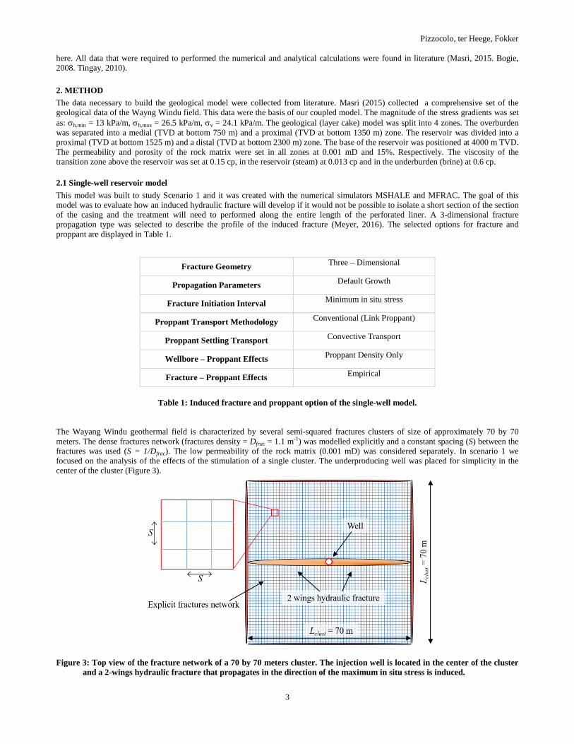
The Wayang Windu geothermal field is characterized by several semi-squared fractures clusters of size of approximately 70 by 70
meters. The dense fractures network (fractures density = Dfrac = 1.1 m-1) was modelled explicitly and a constant spacing (S) between the
fractures was used (S = 1/Dfrac). The low permeability of the rock matrix (0.001 mD) was considered separately. In scenario 1 we
focused on the analysis of the effects of the stimulation of a single cluster. The underproducing well was placed for simplicity in the
center of the cluster (Figure 3).
Figure 3: Top view of the fracture network of a 70 by 70 meters cluster. The injection well is located in the center of the cluster
and a 2-wings hydraulic fracture that propagates in the direction of the maximum in situ stress is induced.

Pizzocolo, ter Heege, Fokker
4
The aim of this model is to evaluate how and where a hydraulic fracture that is stimulated in a long perforated liner develops. Moreover,
with the single-well model it is be also possible to understand if the injected volume necessary to develop a hydraulic fracture that could
reach the extremes of the fractures cluster were technically feasible.
To customize the design of the fracturing treatment for the special conditions of the Wayang Windu field is essential to increase the
chances of success of the stimulation. Weijers (2002) and Dingwei (2011) suggested that using a smaller proppant grain size, in
combination with a short perforated interval and a high pump rate, will help to maximize the effectiveness of the hydraulic treatment.
To additionally enhance the aperture of the induced fracture, the fluid viscosity was augmented during the treatment.
2.2 1-Way coupled model
The coupled model was created to study Scenario 2. Such a model was needed because injecting not native fluid in the subsurface
changes the thermo-hydro-mechanical properties of the rock matrix that is influenced by the injection and all these components
mutually interacts (Gaucher, 2015).
Figure 4: 1-Way coupled system. The output for a model is used as part of the input of the following model.
In the same way that it was shown in the previous section, the single-well reservoir model of the Wayang Windu field was made with
the numerical simulator MSHALE. Again, a layer cake geological model was defined using the data collected from literature. Several
adjacent fractures clusters were considered and the injection well was placed in the center of one of the them (Figure 5). In this case the
dense fractures network was modelled implicitly by means of enhanced leakoff value of the rock matrix. Moreover, it was considered
that the fractures clusters are 100 meters high and that it was possible to isolate a short interval in the casing in the center of the cluster
height.
Figure 5: Top view of the fracture network made of several 70x70 meters clusters. The injection well is located in the center of
one of the cluster. In this case the dense fractures network within the clusters was modelled implicitly in terms of
enhanced leakoff of the rock matrix.

Pizzocolo, ter Heege, Fokker
5
The dynamic reservoir model was created with the flow simulator Eclipse (Figure 6). The horizontal size of the dynamic flow model is
1420 by 1420 m. The layer cake geological system matched the one of the single-well reservoir model. The steam-brine contact was set
at 2350 mTVD. The pre-stimulation condition for pressure and temperature were set at 233 bar and 300 °C (at 2580 mTVD). The
borders of the fractures clusters were explicitly modelled using narrow grid cells of 0.1 meters width. The dimensions of the clusters
were the same of the single-well reservoir model. To consider anisotropic permeability, different properties were considered for the
fractures that runs parallel to the direction of the minimum in situ horizontal stress than the fractures that are parallel to the maximum in
situ stress. Moreover, to consider the dense fracture network included in the clusters, an anisotropic permeability was assigned to each
grid block. The grid size within the reservoir was set at 5 meters, while around the fractures it was set at 1 meter and coarsened next to
the boundaries and away from the fractures (Figure 6, left).
Figure 6: Eclipse dynamic flow model mesh. Left: top view of the fracture network (the thick black lines indicates the borders of
the clusters). Center: zoomed view on a set of 4 clusters. The fractures that develop parallel to h,max (red lines, N-S
fractures) have higher permeability of the fractures that run parallel to h,min (green lines, E-W fractures). Right:
zoomed view on the mesh refinement around the cluster’s borders. Within the cluster the rock matrix was modelled with
anisotropic permeability. The main direction of flow stream lines is North-South. (Pizzocolo, 2017).
We considered a situation in which the hydraulic fracture was just stimulated (t0 = end of the hydraulic stimulation). We simulated a
continuous injection (with production rate of 2000 sm3/day) for 5 years. The permeability of the induced fracture (Khyd,frac) was 10 D and
the temperature of the injected fluids was set 30 °C. The porosity of the rock matrix was set at 15%. Because the grid cells of the
explicit fractures network were set very small (0.1 meter), to have a representative transmissibility a very high value of the permeability
was chosen. In the Wayang Windu geothermal, the fractures network is the main pathways for the fluids. For this reason we selected a
permeability of the existing fracture much higher than the permeability of the rock matrix. The vertical permeability of the fractures was
selected equal to the corresponding horizontal permeability, while the vertical permeability of the rock matrix was set as half of the
permeability of the rock in the corresponding horizontal direction.
The results of the temperature and pressure fronts profile after 1, 3 and 5 years of injection were used as input the last stage of the 1-way
coupled model (Figure 4). The thermal (equations 1, 2 and 3) and poroelastic (equation 4) stresses generated around the well by the
injected fluids were calculated following the analytical solutions for a circular horizontal cross section around the injection well in an
infinitely high reservoir proposed by Perkins and Gonzalez (1984, 1985). In their work the total (thermal), radial (th,radial) and tangential
(th,tan) thermal stresses generated by the temperature gradient are given by:
𝜎𝑡ℎ𝑒𝑟𝑚𝑎𝑙 = 𝛼 ∙ 𝐸
1−𝑣 ∙ (𝑇𝑟 − 𝑇𝑤) (1)
𝜎𝑡ℎ,𝑟𝑎𝑑𝑖𝑎𝑙 = 𝛼 ∙ 𝐸
1−𝑣 ∙ (𝑇𝑟 − 𝑇𝑤) ∙
1
𝑟2 ∙ ∫ 𝑟 𝑑𝑟𝑟𝑎
𝑟0 (2)
𝜎𝑡ℎ,𝑡𝑎𝑛 = 𝛼 ∙ 𝐸
1−𝑣 ∙ (𝑇𝑟 − 𝑇𝑤) ∙
1
𝑟2 ∙ [∫ 𝑟 𝑑𝑟𝑟𝑎
𝑟0− 𝑟2] (3)
Where is the coefficient of thermal expansion, Ethe Young’s modulus, v the Poisson’s ratio, Tr the in situ temperature of the
reservoir, Tw the temperature of the injected water, r0 is the radius of the well and ra indicates the radial distance from the injection well.
Perkins and Gonzalez also gave a solution to calculate the poroelastic stress that results from the injection of water:
𝜎𝑝𝑜𝑟𝑜 = 𝛽 ∙ 1−2𝑣
1−𝑣 ∙ (𝑃𝑓𝑖𝑛 − 𝑃𝑖𝑛𝑗) ∙ 𝑓𝑘 (4)
In equation 4 represents the Biot’s coefficient and fk is Koning’s factor (in this case, fk = 0.5). This factor is necessary to consider the
ellipsoidal distribution of the pore pressure around the fracture’s surfaces (Koning, 1980). The poroelastic stress affects the hosting
medium in the same way in all direction.
Pizzocolo, ter Heege, Fokker
6
Thermal tensile will initiate and propagate when the combination of the tangential thermal stress and the poroelastic stress overcomes
the initial minimum in situ stress. In other words, if h,min,final (equation 5), the perturbated by the injection of fluids minimum in situ
stress, is positive (tensile state, h,min,final > 0), tensile fractures are expected to develop in the direction of the h,max.
𝜎ℎ,𝑚𝑖𝑛,𝑓𝑖𝑛𝑎𝑙 = 𝜎𝑡ℎ𝑒𝑟𝑚𝑎𝑙 + 𝜎𝑝𝑜𝑟𝑜 + 𝜎ℎ,𝑚𝑖𝑛,𝑖𝑛𝑖𝑡𝑖𝑎𝑙 (5)
The rock formation around the wellbore’s wall is damaged by the drilling procedure and by the stress concentration that can produce
breakouts and generate short tensile fractures. For this reason it was assume that the rock matrix in the vicinity of the wellbore does not
have tensile strength. Another aspect to consider it is related to the shear failure (and consequent slip movement) of the existing
fractures. If the injection of fluid in the rock matrix lowers the minimum horizontal stress below a certain level, shear failure (|h,min,final
|< |shear failure limit|), or hydro-shearing, may occur on the fractures that develop in the direction of the h,min. The shear failure limit
was calculated with the Mohr-Coulomb frictional failure theory. During the hydraulic fracturing treatment the effect of the provoked
overpressure is not limited to the region where the fractures are open and propped but will propagate further (Figure 1). Increasing the
pore pressure will reduce the compressive stress, facilitating the slipping of the existing fractures. The shear failure limit has been
calculated with the Mohr-Coulomb frictional theory. Because it was not possible to find precise mechanical data of the fractures, it was
used a coefficient of friction of 0.6 and zero cohesion was assumed. An additional benefit of inducing shear slip is given by the
additional aperture (shear dilution) created by the roughness of the fractures walls. Moreover, the fractures will not slip back to the
initial position when the injection of fluid will stop, maintaining part of the enhanced aperture given by the shear slip (naturally propped
fractures).
3. RESULTS
3.1 Scenario 1
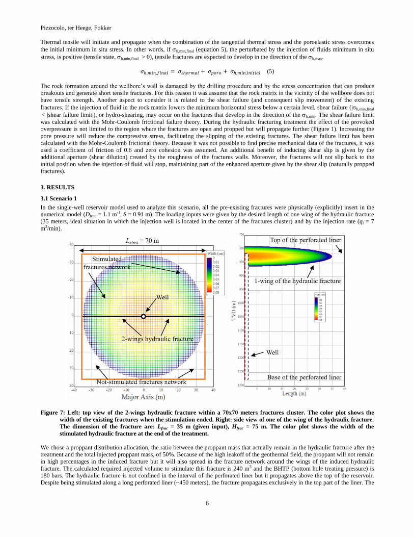
In the single-well reservoir model used to analyze this scenario, all the pre-existing fractures were physically (explicitly) insert in the
numerical model (Dfrac = 1.1 m-1, S = 0.91 m). The loading inputs were given by the desired length of one wing of the hydraulic fracture
(35 meters, ideal situation in which the injection well is located in the center of the fractures cluster) and by the injection rate (qi = 7
m3/min).
Figure 7: Left: top view of the 2-wings hydraulic fracture within a 70x70 meters fractures cluster. The color plot shows the
width of the existing fractures when the stimulation ended. Right: side view of one of the wing of the hydraulic fracture.
The dimension of the fracture are: Lfrac = 35 m (given input), Hfrac = 75 m. The color plot shows the width of the
stimulated hydraulic fracture at the end of the treatment.
We chose a proppant distribution allocation, the ratio between the proppant mass that actually remain in the hydraulic fracture after the
treatment and the total injected proppant mass, of 50%. Because of the high leakoff of the geothermal field, the proppant will not remain
in high percentages in the induced fracture but it will also spread in the fracture network around the wings of the induced hydraulic
fracture. The calculated required injected volume to stimulate this fracture is 240 m3 and the BHTP (bottom hole treating pressure) is
180 bars. The hydraulic fracture is not confined in the interval of the perforated liner but it propagates above the top of the reservoir.
Despite being stimulated along a long perforated liner (~450 meters), the fracture propagates exclusively in the top part of the liner. The
Pizzocolo, ter Heege, Fokker
7
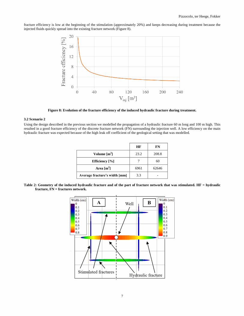
fracture efficiency is low at the beginning of the stimulation (approximately 20%) and keeps decreasing during treatment because the
injected fluids quickly spread into the existing fracture network (Figure 8).
Figure 8: Evolution of the fracture efficiency of the induced hydraulic fracture during treatment.
3.2 Scenario 2
Using the design described in the previous section we modelled the propagation of a hydraulic fracture 60 m long and 100 m high. This
resulted in a good fracture efficiency of the discrete fracture network (FN) surrounding the injection well. A low efficiency on the main
hydraulic fracture was expected because of the high leak off coefficient of the geological setting that was modelled.
HF FN
Volume [m3] 23.2 208.8
Efficiency [%] 7 60
Area [m2] 6961 62646
Average fracture’s width [mm] 3.3 -
Table 2: Geometry of the induced hydraulic fracture and of the part of fracture network that was stimulated. HF = hydraulic
fracture, FN = fractures network.
Pizzocolo, ter Heege, Fokker
8
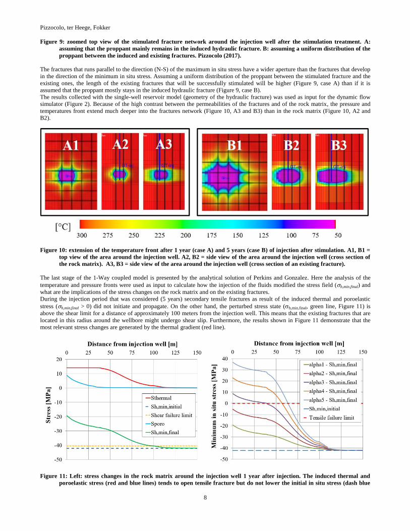
Figure 9: zoomed top view of the stimulated fracture network around the injection well after the stimulation treatment. A:
assuming that the proppant mainly remains in the induced hydraulic fracture. B: assuming a uniform distribution of the
proppant between the induced and existing fractures. Pizzocolo (2017).
The fractures that runs parallel to the direction (N-S) of the maximum in situ stress have a wider aperture than the fractures that develop
in the direction of the minimum in situ stress. Assuming a uniform distribution of the proppant between the stimulated fracture and the
existing ones, the length of the existing fractures that will be successfully stimulated will be higher (Figure 9, case A) than if it is
assumed that the proppant mostly stays in the induced hydraulic fracture (Figure 9, case B).
The results collected with the single-well reservoir model (geometry of the hydraulic fracture) was used as input for the dynamic flow
simulator (Figure 2). Because of the high contrast between the permeabilities of the fractures and of the rock matrix, the pressure and
temperatures front extend much deeper into the fractures network (Figure 10, A3 and B3) than in the rock matrix (Figure 10, A2 and
B2).
Figure 10: extension of the temperature front after 1 year (case A) and 5 years (case B) of injection after stimulation. A1, B1 =
top view of the area around the injection well. A2, B2 = side view of the area around the injection well (cross section of
the rock matrix). A3, B3 = side view of the area around the injection well (cross section of an existing fracture).
The last stage of the 1-Way coupled model is presented by the analytical solution of Perkins and Gonzalez. Here the analysis of the
temperature and pressure fronts were used as input to calculate how the injection of the fluids modified the stress field (h,min,final) and
what are the implications of the stress changes on the rock matrix and on the existing fractures.
During the injection period that was considered (5 years) secondary tensile fractures as result of the induced thermal and poroelastic
stress (h,min,final > 0) did not initiate and propagate. On the other hand, the perturbed stress state (h,min,final, green line, Figure 11) is
above the shear limit for a distance of approximately 100 meters from the injection well. This means that the existing fractures that are
located in this radius around the wellbore might undergo shear slip. Furthermore, the results shown in Figure 11 demonstrate that the
most relevant stress changes are generated by the thermal gradient (red line).
Figure 11: Left: stress changes in the rock matrix around the injection well 1 year after injection. The induced thermal and
poroelastic stress (red and blue lines) tends to open tensile fracture but do not lower the initial in situ stress (dash blue

Pizzocolo, ter Heege, Fokker
9
line) enough to generate new tensile fractures: the final minimum in situ stress (green line) is a compression state
everywhere. Hydroshearing might occur on a radius of 100 meters around the injection well (crossing point between the
green and the dashed yellow line). Right: sensitivity analysis over the coefficient of thermal expansion. alpha1 = 0.1E-4
1/°C, alpha2 = 0.2E-4 1/°C, alpha3 = 0.3E-4 1/°C, alpha4 = 0.4E-4 1/°C, alpha5 = 0.5E-4 1/°C.
The mechanical properties of the rock that mostly influence the calculation of the thermal stress (equation 1) are the Young’s modulus
(E) and the coefficient of thermal expansion (). To take into account the uncertainties in the measurements of these two parameters,
sensitivities analysis were ran for the range of values of the Young’s modulus and of the coefficient of thermal expansion that can be
found in volcanic rocks. The Indonesian volcanic rock have Young’s modulus that typically last in the range of 7 – 10 GPa and for these
values the calculated h,thermal does not varies significantly. On the other hand, for the range of the coefficient of thermal expansion that
can be measured in such rocks ( = 0.1E-4 – 0.5E-4 1/°C), tensile cracking will happen. For ≥ 0.3E-4 1/°C, tensile fractures will
propagate in the rock matrix around the injection well (Figure 11, right).
4. DISCUSSION
Two different scenarios were studied in this work (Figure 2). To analyze the development of a hydraulic fracture stimulated along a very
long perforated liner, a single-well reservoir model was built. Analyzing the results of this model it seems that a tensile fracture reaching
the extremes of the 70 by 70 meters cluster to be technically feasible (Figure 7). However the dense fracture network around the
injection well would lead to a very low fracture efficiency (Figure 8). Depending on what is the target of the stimulation, a low fracture
efficiency might not have a negative impact on the effectiveness of the treatment. The efficiency of the induced fracture will be low
because the injected fluids and proppant will flow rapidly into the dense fractures network of the geothermal reservoir. If the goal was to
develop a long hydraulic fracture in order to connect as many possible fractures that cross the path of the induced one, then a low
efficiency strongly influence the effectiveness of the stimulation. On the other hand, if the goal of the treatment is to stimulate as many
existing fractures possible, and the length of the induced one is not of primary importance, then injected several cubic meters of fluids
(and proppant) at pressure higher than the in-situ one in the fractures network, might shear slip several existing fractures and
consequentially improved production.
The bigger limitation of inducing a hydraulic fracture along a very long perforated liner is that it will mainly develop on top of the
perforated liner at the border between the reservoir’s top and the caprock (Figure 7). This was expected because the difference between
the minimum horizontal stress of the top and the base of the perforated interval is very high (hor,top << hor,base), the hydraulic fracture
will start develop as soon as the injection pressure will be enough to overcome hor,top and the fluid will immediately start flowing in the
top part of the reservoir. Moreover, if a stress barrier is not present the fracture height will not be confined and the induced fracture
develop vertically above the caprock instead than deeper into the geothermal reservoir.
Finally, if it would not be possible to isolate a short internal it must not be underestimate the risk of jeopardize the integrity of the well
or to damage the perforated liner via local plastic buckling when the liner undergo high shear stress (Dusseault, 2001).
A hydraulic fracture treatment would be much more effective if it would be possible to isolate a shorter perforated interval (Scenario 2).
In this case it would be possible to target the part of the geothermal reservoir that would benefit more from the stimulation treatment. In
Figure 9 it is shown that it is possible to overcome the geological and technical challenges and induce hydraulic fractures that penetrate
deep into a geothermal field. The single-well model can be used to quantitatively analyze the efficiency of the stimulation treatment.
Unfortunately in this model is not possible to introduce the degradation coefficient for the proppant. The challenges that the in situ
condition of many geothermal environments present, need to be properly evaluated because the proppant will deteriorate quicker than in
the typical settings where hydraulic fracturing is performed. This means that it will be necessary to perform extra stimulations of the
geothermal system earlier than expected to maintain the production at economically profitable levels.
Introducing the geometry of the hydraulic fracture into the flow simulator we evaluated the extensions and the shapes of the cooling and
pressure fronts. The rock matrix has poorly connected porosity. The fluid it is stored in the rock matrix as well, but because of the bad
connection between the pore, it is difficult to activate. To improve the production rate it is essential to stimulate the interconnected
fracture network. This can be achieved also by shearing existing fractures or by propagate new tensile ones via thermal-hydro-
mechanical stimulation. The pressure and temperature profiles calculated with the dynamic flow simulator were used as input for the
last stage of the 1-way coupled model: the analytical calculations. The thermal and poroelastic stresses (Figure 11) generated by the
temperature and pressure gradients were not large enough to initiate and propagate new tensile fractures. The biggest contribution to the
stimulation was given by the thermal gradient (thermal >> poro) and the cooling effect penetrate in the geothermal field much deeper
(110 meters) than the overpressure one (40 meters). After 1 year of continuous injection the fractures located up to a distance of 140
meters from the injection well could be reactivated because of shear failure.
Finally, sensitivity analyses were conducted on the parameters that influence the development of the thermal stresses in a geothermal
system: Young’s modulus (E), and coefficient of thermal expansion (). At the range of magnitudes of E typical of Indonesian volcanic
subsurface (7-10 GPa), the values of the calculated stress perturbation did not increase enough to change significantly the results. On the
other hand, for values of coefficient of thermal expansion that can be found in such geological systems, long thermal tensile fractures
can develop around the injection well.
5. CONCLUSIONS
After years of exploiting steam, geothermal wells may need stimulation to remain economically profitable. A forward-looking
production strategy necessitate the investigation of stimulation options in case production is diminishing. Hydraulic fracturing can be a
suitable technique to improve steam production or to create new geothermal pay zones. The goal is to stimulate the area around the well
by connecting pre-existing fractures or by creating new pathways for the steam through the initiation and propagation of new tensile
fractures. Performing such a treatment in a geothermal reservoir presents several important challenges. The technical and geological
Pizzocolo, ter Heege, Fokker
10
challenges that might affect the effectiveness and efficiency of the stimulation were investigated. If a hydraulic fracturing treatment is
assessed to be technically feasible, it must be carefully tailored to the geothermal field. A close connection between dynamic flow
simulators and geomechanical models is essential to numerically simulate the effectiveness of this stimulation technique, a close
connection between dynamic flow simulators and geomechanical models is essential. To properly evaluate the stress changes induced
by the pressure and temperature gradients in the geothermal field around the injection well, we linked in a 1-way coupled fashion
numerical simulators and analytical solutions to connect the evolving fluid pressures and temperature with the changes in the stress field
around the well. Hydraulic fracturing will not be the proper stimulation technique when isolation of a short section of the liner is not
possible or is too expensive. We have shown that in this case, the stimulation would not be effective because the induced fracture will
only propagate on the top part of the perforated liner. If to isolate a shorter perforated interval, in order to target the section of the
geothermal that mostly need stimulation, it is possible, then, with a tailored treatment design, it is doable to perform an effective
fracturing treatment. Finally, the high injectivity that generates the high fracture leakoff can also be exploited to apply alternative
stimulation approaches. The fast penetration of pressure and temperature fronts into the reservoir can make thermal and acid stimulation
to be valuable alternatives to hydraulic fracture stimulation.
REFERENCES
Bogie, I. et al., Overview of the Wayang Windu geothermal field, West Java, Indonesia, 37, Geothermics, (2008), 347-365.
Dingwei, W. et al., Case study: Massive hydraulic fracturing in volcanic gas, China, SPE 141543, (2011).
Dusseault, M., et al., Massive multi stage hydraulic fracturing for oil and gas recovery from low mobility reservoir in China, Petroleum
Drilling Techniques, 39, (2011), 6-16.
Gaucher, E., et al., Induced seismicity in geothermal reservoir: physical processes and key parameters, Proc. World Geoth. Congr.,
(2015).
Glauser, W. et al., Do perforated completion have value for engineered geothermal systems, Book: Effective and sustainable hydraulic
fracturing, IntechOpen, (2013).
Konig, E., Fractured Water Injection Wells - Analytical Modeling of Fracture Propagation, SPE 14684, 1985.
Legarth, B., et al., Hydraulic fracturing in a sedimentary geothermal reservoir: results and implications, Int. Journal of Rock Mechanics
and Mining Sciences, 42, (2005), 1028-1041.
Masri, A., et al., Structural permeability assessment using geological structural model integrated with 3D geomechanical study and
discrete fracture network model in Waynag Windu geothermal field (West Java, Indonesia), Proc. 14th workshop on Geothermal
Res. Engineering, (2015).
Meyer, B.R., MFRAC User’s guide, 2016.
Perkins, T.K. and Gonzalez, J.A., Changes in Earth Stresses Around a Wellbore Caused by Radially Symmetrical Pressure and
Temperature Gradients, Soc. Pet. Eng. J., (1984), 129-40.
Perkins, T.K., and Gonzalez, J.A., The Effect of Thermoelastic Stresses on Injection Well Fracturing, Soc. Pet. Eng. J., (1985), 78-88.
Pizzocolo, F. and Fokker, P.A..: Coupling Flow-Geomechanical Model for Stimulation of Fractured Geothermal Fields, American Rock
Mechanics Association, ARMA-2017-0474, 2017.
Tingay, M. et al., Present-day stress field of Southeast Asia, Tectonophysics, (2010).
Weijers, L. et al., Hydraulic fracturing in a deep, naturally fractured volcanic rock in Japan – design considerations and execution
results, SPE 77823, (2002).