numerical analysis of welded beam-column joints in
TRANSCRIPT

Number 21, Year 2020 Page 30–44 Numerical analysis of welded beam-column joints in aluminum structures
Hržić, T, Boko, I, Torić, N
https://doi.org/10.13167/2020.21.3 30
NUMERICAL ANALYSIS OF WELDED BEAM-COLUMN JOINTS IN ALUMINUM STRUCTURES
Scientific paper
(Received: 22 May 2020; accepted: 23 September 2020) Tin Hržić University of Split, Faculty of Civil Engineering, Architecture and Geodesy, Master student Corresponding author: [email protected]
Ivica Boko University of Split, Faculty of Civil Engineering, Architecture and Geodesy, Full Professor
Neno Torić University of Split, Faculty of Civil Engineering, Architecture and Geodesy, Associate Professor Abstract: The objective of this study is to compare the performance for welded beam-column joints in aluminum structures using moment-rotation diagrams and to evaluate the influence of welding on joint rigidity. A nonlinear numerical calculation of welded beam–column joints is performed using the finite element method. Material and geometric nonlinearities were included in the model. The connection was analyzed for two cases: variants with and without welded stiffener plates. Two material models were used. The first was derived from the applicable standard for aluminum structures, while the other was based on the results of a previous material study and calibrated using a separate numerical calculation. From the results of the calculations, moment-rotation diagrams for different geometries and material properties of joints were constructed and compared. The obtained moment-rotation diagrams for the stiffened and unstiffened joints demonstrate that stiffening of the joints in aluminum structures improves the properties of the joint in terms of higher rigidity, resistance, and ductility, regardless of the existence of the heat affected zone.
Keywords: Aluminum; heat affected zone; welded beam-column joint; nonlinear analysis; material nonlinearity; finite-element method.
Number 21, Year 2020 Page 30–44 Numerical analysis of welded beam-column joints in aluminum structures
Hržić, T, Boko, I, Torić, N
https://doi.org/10.13167/2020.21.3 31
1 INTRODUCTION
With the increasing use of structural aluminum in construction, the behavior of this material should be examined under various load conditions. Therefore, this study evaluates the performance of welded beam–column joints in aluminum structures and the influence of welding on joint rigidity. The local response of the weld and heat-affected zone (HAZ) under load for different aluminum alloys has been researched since the 1950s. Scott and Gittos [1] studied welds of 6082 alloy made with 5556 filler material of 3 mm and 13 mm thicknesses to characterize the strength of the base material and weld after the welding process. The tests showed that the tensile properties of the weld zone were worse than those of the base metal; however, inthe weld, the material had better toughness. Moreover, strain localization can affect the deformation capacity of this alloy. Weld and HAZ zone properties of 6082-T6 alloy were also studied by Matusiak and Larsen [2] and Matusiak [3]. In this study, the strength and hardiness of butt and fillet welds were tested to show the dependence between the mechanical properties and distance from the weld center to the point where the material was tested. The tests showed that the metal had poorer properties in the vicinity of the weld than in the weld or base material. A numerical model was constructed, and it was concluded that tri-axial stress is present in the HAZ, which is the result of the material being constrained by the surrounding material with better mechanical properties. The results from these experiments are used in this study to validate the material model, as described in Chapter 4.
In addition to examining the properties of welded aluminum, the properties of aluminum elements that were welded and then exposed to tensile, compressive, or bending forces were also examined. Edlund [4] conducted a series of experiments on buckling tests of T-section aluminum beams, with and without transverse welds in compression with load eccentricity. Significant strength reduction from the welds was observed; however, reduction was highly dependent on the weld location. Tension tests were performed on specimens of the base material and HAZ. The results obtained from these tests, in the form of stress-strain diagrams, were used as the input in the finite-element method (FEM) model. The model used shell elements and showed good agreement with the experimental data in terms of force-displacement curves. Wang [5] studied the failure prediction of fillet and butt welds, beam-to-column connections loaded in tension, and welded beams in bending. He created an FEM model to estimate the ductility and fracture load for previously mentioned cases. Alloy 6082-T6 was modeled using an anisotropic plasticity model and inhomogeneous work-hardening properties for the HAZ. Generally, the model results were good but highly mesh-dependent. This led to refinement of the model by implementing local thinning in the solver. The results were scientifically improved; however, the set up and analysis times were longer.
The influence of HAZ on the behavior of the welded assemblies is mainly studied on stiffened aluminum panels during compression or bending. Zha and Moan [6] conducted research on aluminum plates with flatbar stiffeners in compression with a torsional buckling failure mode. To determine the impact of HAZ, an FEM model was created and used on the model with and without HAZ. The study showed that the strength of a panel is affected by the HAZ properties in the transverse direction to the load, and the strength of the element is reduced by 15% on average. Sensharma, Collette, and Harrington [7] performed numerical calculations on aluminum stiffened panels in compression, tension, and bending. Three approaches were used to assign the material properties. In the first approach, the whole model is associated with a base material. In the second, the HAZ zone is localized around the welds, and in the third, all models are associated with HAZ material. The third approach demonstrated a 25% decrease in the overall panel strength compared to the second approach. The spread of material yield through a fixed portion of the model was used to determine the strength of a panel because of model limitations. It is not straightforward to model extensive strain localization and material failure using shell elements.
For the joints in aluminum structures, most studies have been conducted on the elements that compose joints and do not observe the behavior of the joints in terms of rotational stiffness. De Matteis and Mazzolani [8] conducted comprehensive research on T-stub aluminum joints. Here, 26 different joints were tested under monotonic and cyclic loading. De Matteis, Mandara, and Mazzolani [9] used the results from this research to calibrate the FEM model. The analysis showed that, contrary to steel, the failure mechanism of aluminum T-stub cannot be clearly defined owing to the strong influence of the alloy hardening features. Brando et al. [10] studied the influence of column axial load and HAZ on the strength of an aluminum column web in tension. To investigate the interconnection between the component strength and column axial force, a parametric numeric analysis was performed. The results of the study proposed formulas for component design according to Eurocode, by which web strength can be calculated as a function of the base material and HAZ strength. The influence of welding on joint rigidity has not yet been researched; however, the presented works provide knowledge and guidelines for each

Number 21, Year 2020 Page 30–44 Numerical analysis of welded beam-column joints in aluminum structures
Hržić, T, Boko, I, Torić, N
https://doi.org/10.13167/2020.21.3 32
segment required to model joints in aluminum. In this study, all of these elements are combined to create the FEM model required to analyze this problem. The chapters prior to Chapter 4 contain the basic knowledge needed for readers not familiar with structural aluminum and its applications to understand the issue of welded joints in aluminum.
1.1 Properties of aluminum compared to steel
The mechanical properties of structural aluminum are generally inferior to the properties of structural steel. however, there are a series of aluminum alloys that have better mechanical properties than those of structural steel but are not used because of their low extrudability [11]. Aluminum’s advantages over steel are primarily lower density, better resistance to atmospheric influences, toughness at low temperatures, and mechanical properties that improve with temperature reduction [12]. The main disadvantage of aluminum is its behavior at high temperatures. Thermal elongation is twice as large as that of steel, and the reduction of mechanical properties at elevated temperatures is faster and higher than that of steel. The properties of aluminum compared to steel are listed in Table 1. In addition, degradation of the properties in the HAZ is apparent around the welds [13].
Table 1 Properties of aluminum alloys with respect to steel [14]
Physical properties Aluminum alloys Steel
Melting point 660 °C 1425 - 1540 °C
Density at 20 °C 2700 kg/m3 7850 kg/m3
Thermal elongation 23∙10-6
°C-1
12∙10-6
°C-1
Specific heat capacity 920 J/kg°C 440 J/kg°C
Thermal conductivity 240 W/m°C 54 W/m°C
Elasticity modulus 70 000 N/mm2 210 000 N/mm2
Shear modulus 27 000 N/mm2 81 000 N/mm2
Poisson`s ratio 0.3 0.3
2 ALUMINIUM ALLOYS
Different elements are added to aluminum during the alloying process to produce alloys of different chemical compositions and mechanical properties. Several elements have proven to be suitable for this purpose, such as magnesium (Mg), manganese (Mn), zinc (Zn), copper (Cu), and silicon (Si), which are used either individually or in combination with more alloying elements. There are two types of alloys that are divided according to the method of processing: wrought alloys and cast alloys. Wrought alloys are suitable for extruding, rolling, etc. To enhance the properties of aluminum alloys regarding the ultimate tensile strength, hardiness, stiffens etc., alloys can be plastically deformed or subjected to different forms of heat treating.
2.1 Alloy EN AW-6082 T6
In this study, aluminum alloy EN AW-6082 T6 was used as the base material because EN AW-6082 is one of the most commonly used structural alloys owing to its high strength and extrudability index [11]. In addition, test data regarding stress-strain diagrams for this alloy are available. The alloying elements for this alloy are Mg, Si, and Mn. Alloy EN AW-6082 T6is used in the production of trusses, bridges, cranes, buildings, and generally in areas where more stress occurs in the material. The alloy is available in the form of extruded profiles, tubes, plates, and sheets. From Table 2, in which the chemical composition of the alloy is listed, this alloy contains higher amounts of Mg. Mg controls the grain structure of the metal, which results in a higher strength of the alloy. EN AW-6082 has good weldability, and alloys 4043 or 5356 are recommended as filler alloys [15]. The corrosion resistance of this alloy is mainly owing to the dominant Mg content, which increases the resistance of the aluminum alloy to alkaline solutions that form lime, concrete, and sodium carbonate.
Table 2 Chemical composition of alloy EN AW-6082 [16]
Element Fraction [%]
Silicon (Si) 0.7–1.3

Number 21, Year 2020 Page 30–44 Numerical analysis of welded beam-column joints in aluminum structures
Hržić, T, Boko, I, Torić, N
https://doi.org/10.13167/2020.21.3 33
Magnesium (Mg) 0.6–1.2
Manganese (Mn) 0.4–1.0
Iron (Fe) ≤ 0.5
Chromium (Cr) ≤ 0.25
Zinc (Zn) ≤ 0.2
Titan (Ti) ≤ 0.1
Copper (Cu) ≤ 0.1
Other (individually) ≤ 0.05
Other (total) ≤ 0.15
Aluminum (Al) rest
Mark T6 represents the temper state of the aluminum alloy, which is heat-treated and then artificially aged [17]. Element was held at a temperature of 530 °C for 24 h. This causes smelting of alloying elements, which are then implanted in the aluminum matrix, and after quenching in water, this state is retained. Later, the process of artificial ageing was carried out. The element was heated again to a temperature of 180 °C for 18 h and cooled naturally. These processes improve the mechanical properties of alloys, mainly the ultimate strength.
3 WELDING OF ALUMINIUM ALLOYS
Welding is defined as the process of connecting materials using heat. Heat is most commonly created by electric current or friction. The advantages of welded aluminum structures are related to savings in labor and materials. For example, in mechanically connected construction, the mass of the connectors is approximately 10% of the total mass of the construction. With welding, the ratio decreases to approximately 4%, which ultimately reduces the cost of construction. The biggest drawback of the welding process in aluminum structures is the occurrence of a HAZ (explained in section 3.1), which often results in strength reduction of the base material in the vicinity of the weld. As another drawback, controlled conditions in the welding zone are required for the weld to be of sufficient quality. The required conditions, using currently available technologies, can only be ensured in workshops. The connection of aluminum on site can only be performed using mechanical coupling or gluing.
The welding procedures most commonly used in the design of aluminum structures are as follows:
gas welding,
arc welding (electrodes),
welding under the protection of inert gas with a permanent electrode (Tungsten inert gas process (TIG)) or a consumable electrode (Metal inert gas process(MIG)),
laser welding,
friction-welding.
Welding under gas protection (TIG and MIG) is the most widespread technique for welding elements in aluminum structures that are effectively used in everyday practice. The difference between TIG and MIG welding is the type of electrode. During TIG welding, an electro-arc is held between the tungsten electrodes and aluminum that is being welded. The electrode and molten base metal are protected by an inert gas (argon, helium), and an additional material (filler) is inserted manually. In MIG welding, an electro-arc is formed between the consummated wire electrode, which is mechanically drawn from the coil and dosed, and the aluminum that is welded. The quality of the weld depends on several parameters: the selection of the correct welding process, strength of electro-arc current, size of the electrode, speed of welding, choice of inert gas, type of joint, competence of the welder, properties of the base material, and properties of the electrode material. If any of these parameters deviate from the standardized, unwanted distortion of the elements, cracks, or interruptions in the weld can occur.
3.1 HAZ
The occurrence characteristic of aluminum and its alloys is the change in the base material properties in the zone around the weld, called the HAZ. Metal in the HAZ can have poorer or better characteristics than those of the base

Number 21, Year 2020 Page 30–44 Numerical analysis of welded beam-column joints in aluminum structures
Hržić, T, Boko, I, Torić, N
https://doi.org/10.13167/2020.21.3 34
material, depending on the combination of the base material and filler [18]. When designing welded constructions in which hardened alloys or artificially aged alloys are used, this occurrence must be considered because it results in significant degradation of the properties of the base material.
Figure 1 Characteristic hardness diagrams in the HAZ for different alloys [19]
The HAZ can be divided into two parts (1 and 2), as shown in Figure 1, depending on the distance from the weld. In area 1, in heat-treated alloys, the metal reaches the temperature of the initial processing, and the degradation of hardiness is significant; however, the process of re-ageing partially restores its properties after the welding process. In area 2, the temperature is lower, and its impact decreases with an increase in the distance from the weld up to point B, where all the characteristics of the base material are valid. The lowest hardiness occurs at the border of these two areas, in point A. In the alloy class 6xxx, in which alloy 6082 belongs, the heat produced by welding can reduce the strength of the base material by up to 50%. The propagation of the HAZ can be reduced by controlling the temperature during the welding process. The temperature of the base material should be monitored before performing a new welding interpass. The temperature may increase owing to the previous weld in the immediate vicinity, excessive air temperature, or insufficient time left for the material to cool between two weld interpasses [18].
When designing aluminum structures, HAZ is assumed to extend a distance bhaz in any direction from a weld, measured as defined in HRN EN 1999-1-1 [20] and shown in Figure 2.
Figure 2 Extent of the HAZ [20]
The HAZ boundaries should be assumed to be straight lines normal to the metal surface, particularly when welding a thin material. However, if surface welding is applied to a thick material, a curved boundary of radius bhaz can be assumed. For an MIG weld laid on unheated material and with interpass cooling to 60 °C or less when multipass welds are laid, the values of bhaz are as follows [20]:
0 < t ≤ 6 mm bhaz = 20 mm,
6 < t ≤ 12 mm bhaz = 30 mm,
12 < t ≤ 25 mm bhaz = 35 mm,
t > 25 mm bhaz = 40 mm.
Har
dnes
s
Har
dnes
s
Har
dnes
s

Number 21, Year 2020 Page 30–44 Numerical analysis of welded beam-column joints in aluminum structures
Hržić, T, Boko, I, Torić, N
https://doi.org/10.13167/2020.21.3 35
4 MATERIAL MODELS
Two material models were used in the numerical analysis of the joints, and they were implemented through stress-strain diagrams. In the first model, all materials were modeled as perfectly elastic plastic materials. This model is chosen to review the applicability of a simple material model versus more advanced models. In EN 1999-1-1, several other material models are addressed (variants of the Ramberg–Osgood model, the most important model for aluminum), which better represent the behavior of aluminum. However, this model was chosen to understand its limitations regarding FEM modeling of aluminum. The diagrams for the second model were obtained based on the tests performed in the works of Dr. Ting Wang [5], [21], and the material model was validated by conducting a numerical test that describes the experiment by Matusiak [3]. A good match was obtained for this validation study.
4.1 Perfectly Elastic plastic material model (material model 1)
Diagrams for the base material and material in the HAZ were constructed using the minimum mechanical properties data for the EN AW-6082 T6 alloy according to the standard HRN EN 1999-1-1, Table 3.2b [20], and are shown in Figure 3. The diagram is a straight line with slope E = 70000 N / mm2 up to the point where the yield strength f0 is
reached. For extruded profiles of thickness 5 mm < t ≤ 15 mm, f0 = 260 N / mm2 for the base material, and f0 = 125
N / mm2 for the material in HAZ [20]. The diagram for the welds shares the same characteristics with two other diagrams, except for the value of f0, which is determined based on the filler alloy. Alloy 5183 was chosen as the filler material for welding according to the recommendations of the standard HRN EN 1999-1-1, Table 3.6 [20], with a characteristic value of 0.2 % proof strength f0 = 210 N / mm2, from HRN EN 1999-1-1, Table 8.8 [20]. After reaching f0, all materials behave ideally plastic until a total deformation of 10% is reached. This point is defined as the breaking point of the material. The maximum total relative deformation is assumed to be the same for all three materials because of the limitations in the current FEM model and inability to track strain independently for these materials. In research by Matusiak [3], the variation in the mechanical properties in the vicinity of the weld bead was studied. He concluded that reduced yield stress and ultimate strength are present in the weld zone. However, greater elongation and higher strain hardening are present in the HAZ than in the base material, except in the narrow zone near the weld where the limit strain is approximately 10%. In the weld, elongation and strain hardening were greater than those in the base material. Thus, the maximum strain is determined based on the previously mentioned strain limit in the vicinity of the weld.
Figure 3 Stress-strain diagrams for the perfectly elastic plastic material model
4.2 Material model derived from the test results (material model 2)
Stress-strain diagrams were defined based on the conducted tests. The results of several tests were statistically processed, and as a result, the parameters for the stress-strain function were determined. The function is defined by the five parameter Voce law for the nonlinear behavior of the materials (1).
𝜎𝑦(�̅�) = 𝑦0+ 𝑄
1(1 − 𝑒(−𝐶1�̅�)) + 𝑄2(1 − 𝑒(−𝐶2�̅�)) (1)
0
50
100
150
200
250
300
0 0,02 0,04 0,06 0,08 0,1
stre
ss [
N/m
m2]
strain [mm/mm]
Base material
HAz
Weld

Number 21, Year 2020 Page 30–44 Numerical analysis of welded beam-column joints in aluminum structures
Hržić, T, Boko, I, Torić, N
https://doi.org/10.13167/2020.21.3 36
Here, y0 is the yield point, and Ci and Qi are the hardening parameters. The stress-strain diagram for the base material EN AW-6082 T6 was constructed based on the work of Professor Matusiak [3], in which tensile tests were carried out on samples of the material taken from the flanges and web of the extruded profile. From multiple tests, the parameters for equation (1) are determined through statistical analysis. In the works of Matusiak [3] and Wang [5] [21], tests were performed on the EN AW 6082 T6 alloy in the HAZ and weld. The mechanical characteristics of the material after welding were observed. The hardness of the material at points in the weld and variable distances from the weld was determined. Then, the hardness was correlated with the material strength. In addition, samples were taken from the weld and its surroundings, and a tension test was performed. As a result of these tests, stress–strain diagrams of the weld and material in the HAZ are constructed, as shown in Figure 4. The parameters required to construct the stress-strain diagrams are listed in Table 3.
Table 3 Parameters for the Voce law equation
Y0 Q1 C1 Q2 C2
Base material 256 52.3 4605 59.5 20.5
HAZ 99 47 669 131 22
Weld 105 42 656 189 13
Figure 4 Stress-strain diagrams for the material model derived from the test results
5 GEOMETRY OF NUMERICAL MODELS
In this study, two variants of the joint between two extruded profiles are observed: variants with and without stiffener plates. Profile cross sections taken from the manufacturer's catalog [22] for EN AW-6082 aluminum alloy are shown in Figure 5. I-shaped profile sections are used to highlight the initial aim of obtaining moment-rotation curves while maintaining the simplicity of the analysis. In practice, extrusion of I-shaped profiles is rare because the shape functionality, which an important advantage of aluminum, is not utilized. The static system of both models is the same, as shown in Figure 6. The static system consists of a column (profile 1) that is mounted vertically and has rigid supports at its ends and a cantilever beam (profile 2) on which the load is applied. At the point of force action, the profile is laterally supported so that there is no loss of element stability and lateral–torsional buckling, which would affect the stress distribution in the joint.
0
50
100
150
200
250
300
350
400
0 0,02 0,04 0,06 0,08 0,1
stre
ss [
N/m
m2]
strain [mm/mm]
Base material
HAz
Weld

Number 21, Year 2020 Page 30–44 Numerical analysis of welded beam-column joints in aluminum structures
Hržić, T, Boko, I, Torić, N
https://doi.org/10.13167/2020.21.3 37
Figure 5 Cross sections of the used profiles Figure 6 Static system of the models
The two profiles are connected by fillet welds. The thickness of the welds is determined according to the following formula: a = 0.7·t, where t is the thickness of the welded element. The fields were 10 mm thick on the flanges and
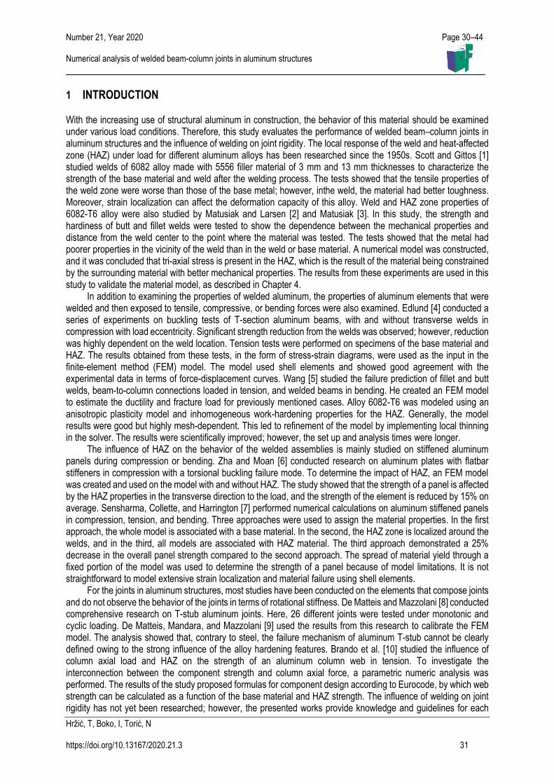
6 mm on the web. The stiffeners are connected with 10 mm fillet welds. The contact between the two elements is modeled as a friction connection with a friction coefficient of 0.69. In Figures 9 and 10, the geometry of the observed models (with and without stiffeners) is shown. The dimensions of the HAZ are determined in accordance with the standard HRN EN 1999-1-1 [20]:
Profile 1, flange - tf = 15 mm → bhaz = 35 mm
Profile 1, web - tw = 14.5 mm → bhaz = 35 mm
Profile 2, flange - tf = 15 mm → bhaz = 35 mm
Profile 2, web - tw = 9 mm → bhaz = 30 mm
Figure 7 Association of the materials in the model without stiffeners [23]
Figure 8 Association of the materials in the model with stiffeners [23]
load
lateral restrain
stiffeners profil1-base material HAZ weld profil 2-base material
profil1-base material profil2-base material weld HAZ
Number 21, Year 2020 Page 30–44 Numerical analysis of welded beam-column joints in aluminum structures
Hržić, T, Boko, I, Torić, N
https://doi.org/10.13167/2020.21.3 38
Figure 9 Geometry of the model without stiffeners Figure 10 Geometry of the model with stiffeners
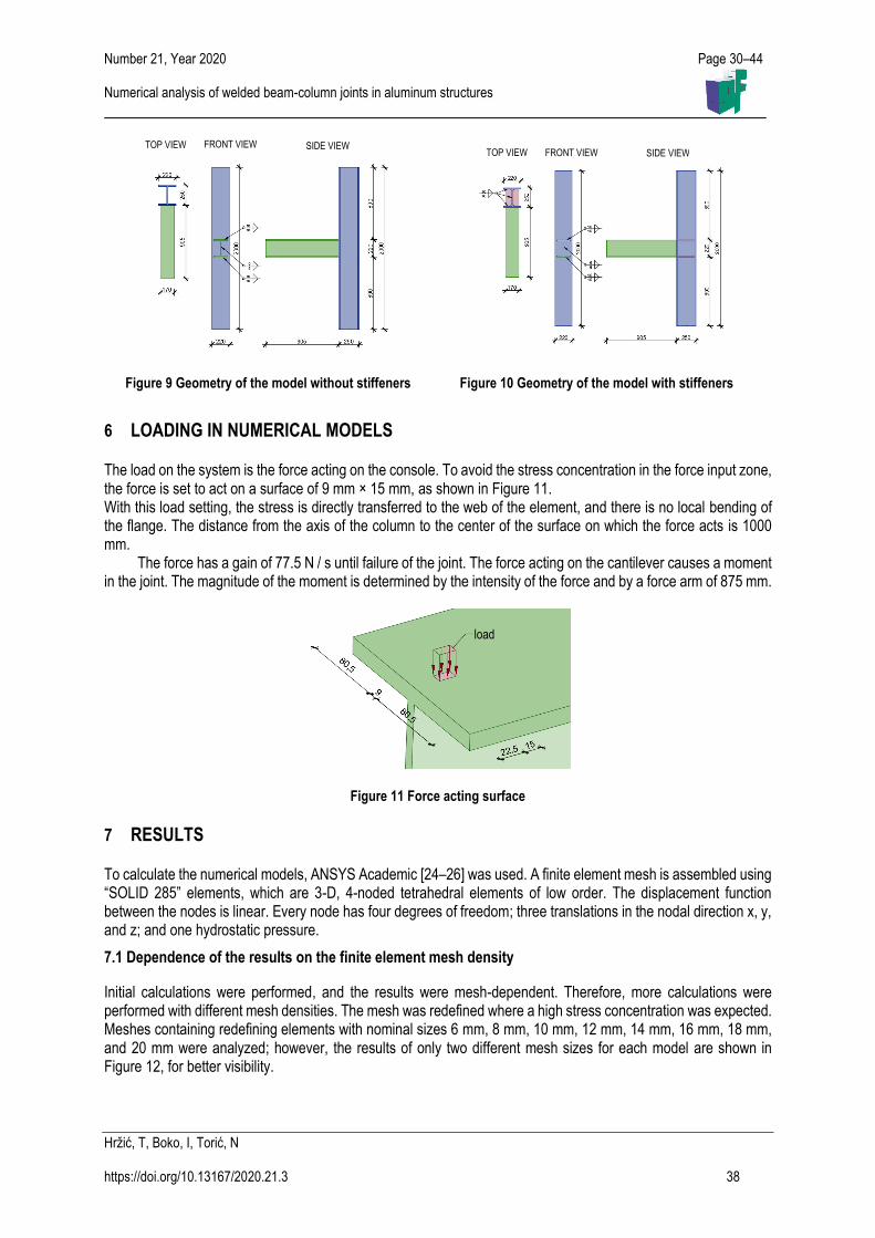
6 LOADING IN NUMERICAL MODELS
The load on the system is the force acting on the console. To avoid the stress concentration in the force input zone, the force is set to act on a surface of 9 mm × 15 mm, as shown in Figure 11. With this load setting, the stress is directly transferred to the web of the element, and there is no local bending of the flange. The distance from the axis of the column to the center of the surface on which the force acts is 1000 mm.
The force has a gain of 77.5 N / s until failure of the joint. The force acting on the cantilever causes a moment in the joint. The magnitude of the moment is determined by the intensity of the force and by a force arm of 875 mm.
Figure 11 Force acting surface
7 RESULTS
To calculate the numerical models, ANSYS Academic [24–26] was used. A finite element mesh is assembled using “SOLID 285” elements, which are 3-D, 4-noded tetrahedral elements of low order. The displacement function between the nodes is linear. Every node has four degrees of freedom; three translations in the nodal direction x, y, and z; and one hydrostatic pressure.
7.1 Dependence of the results on the finite element mesh density
Initial calculations were performed, and the results were mesh-dependent. Therefore, more calculations were performed with different mesh densities. The mesh was redefined where a high stress concentration was expected. Meshes containing redefining elements with nominal sizes 6 mm, 8 mm, 10 mm, 12 mm, 14 mm, 16 mm, 18 mm, and 20 mm were analyzed; however, the results of only two different mesh sizes for each model are shown in Figure 12, for better visibility.
SIDE VIEW SIDE VIEW
FRONT VIEW
load
FRONT VIEW TOP VIEW TOP VIEW

Number 21, Year 2020 Page 30–44 Numerical analysis of welded beam-column joints in aluminum structures
Hržić, T, Boko, I, Torić, N
https://doi.org/10.13167/2020.21.3 39
Figure 12 Different mesh density examples for the models without stiffeners (left) and with stiffeners (right) [24]
To evaluate the differences between the results for the meshes, the displacement of the cantilever edge is shown in Figures 13 and 15. In addition, the largest strains in the models in relation to the force acting on the unstiffened and stiffened models are shown in Figures 14 and 16.
Figure 13 Displacement of the cantilever edge in relation to the force for the unstiffened joint
Figure 14 Largest strain in relation to the force for the unstiffened joint
Figure 15 Displacement of cantilever edge in relation to the force for the stiffened joint
Figure 16 Largest strain in relation to the force for the stiffened joint
By analyzing the diagrams in Figures 13 and 15, for both the unstiffened and stiffened models, the results are divided into two groups depending on the material model used. The failure of the joint occurs earlier when a perfectly elastic plastic material model is applied (material model 1), that is, at a lower force rate than when the material model derived from the test results is applied (material model 2). This is expected because, in the material model derived from the test results (material model 2), hardening occurs in the area of plasticity. The force-displacement
0 10 20 30 40 50
0
20
40
60
80
100
120
140
displacement [mm]
forc
e [
kN]
Material model 1, 6 mm
Material model 1, 8 mm
Material model 1, 14 mm
Material model 1, 20 mm
Material model 2, 6 mm
Material model 2, 8 mm
Material model 2, 14 mm
Material model 2, 20 mm
0 0,02 0,04 0,06 0,08 0,1
0
20
40
60
80
100
120
140
strain [mm/mm]
forc
e [k
N]
Material model 1, 6 mm
Material model 1, 8 mm
Material model 1, 14 mm
Material model 1, 20 mm
Material model 2, 6 mm
Material model 2, 8 mm
Material model 2, 14 mm
Material model 2, 20 mm
0 20 40 60 80
0
50
100
150
200
displacement [mm]
forc
e [
kN]
Material model 1, 6 mmMaterial model 1, 8 mmMaterial model 1, 14 mmMaterial model 1, 20 mmMaterial model 2, 6 mmMaterial model 2, 8 mmMaterial model 2, 14 mmMaterial model 2, 20 mm
0 0,02 0,04 0,06 0,08 0,1
0
50
100
150
200
strain [mmmm]
forc
e [
kN]
Material model 1, 6 mm
Material model 1, 8 mm
Material model 1, 14 mm
Material model 1, 20 mm
Material model 2, 6 mm
Material model 2, 8 mm
Material model 2, 14 mm
Material model 2, 20 mm
Number 21, Year 2020 Page 30–44 Numerical analysis of welded beam-column joints in aluminum structures
Hržić, T, Boko, I, Torić, N
https://doi.org/10.13167/2020.21.3 40
relationship for all mesh densities and for both material models is consistent, and the difference between the curves is minimal until failure occurs. The use of a higher density mesh leads to earlier failure, whereas a system modeled with a rougher mesh achieves larger displacements for the same force intensity and fails later. In Figures 14 and 16, for a higher density mesh, the failure boundary of 10% strain is reached with a force of lower intensity in both models. As before, this is a consequence of the stress localization acting on a smaller surface if the mesh has a higher density and therefore a greater gradient.
7.2 Relevant results
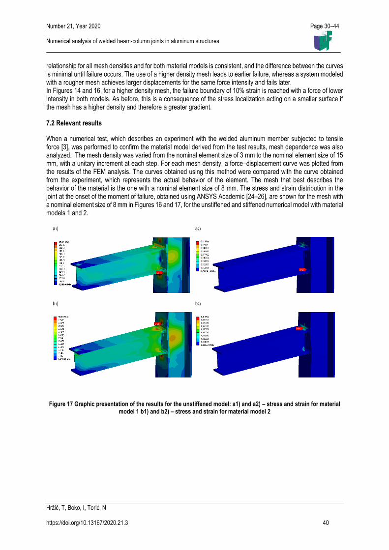
When a numerical test, which describes an experiment with the welded aluminum member subjected to tensile force [3], was performed to confirm the material model derived from the test results, mesh dependence was also analyzed. The mesh density was varied from the nominal element size of 3 mm to the nominal element size of 15 mm, with a unitary increment at each step. For each mesh density, a force–displacement curve was plotted from the results of the FEM analysis. The curves obtained using this method were compared with the curve obtained from the experiment, which represents the actual behavior of the element. The mesh that best describes the behavior of the material is the one with a nominal element size of 8 mm. The stress and strain distribution in the joint at the onset of the moment of failure, obtained using ANSYS Academic [24–26], are shown for the mesh with a nominal element size of 8 mm in Figures 16 and 17, for the unstiffened and stiffened numerical model with material models 1 and 2.
Figure 17 Graphic presentation of the results for the unstiffened model: a1) and a2) – stress and strain for material model 1 b1) and b2) – stress and strain for material model 2
a1)
a2)
b1)
b2)

Number 21, Year 2020 Page 30–44 Numerical analysis of welded beam-column joints in aluminum structures
Hržić, T, Boko, I, Torić, N
https://doi.org/10.13167/2020.21.3 41
In Figure 17, for the unstiffened model, localization of stress occurs in the area where the beam flanges connect to the column. This localization results in rapid strain development, which leads to element failure in the HAZ in the column flange.
From the results of the model with stiffeners, shown in Figure 18, higher utilization of the column web is visible. Part of the web between the column flanges and stiffeners is under high stress, and the HAZ around the stiffeners is exposed to high strain. This effect of higher web utilization could produce better performance of the stiffened joints compared to the unstiffened joints, which are manifested through larger deformations at failure, as shown in Figure 19, and a larger force bearing capacity.
a1)
a2)
b1)
b2)
Figure 18 Graphic presentation of the results for the stiffened model: a1) and a2) – stress and strain for material model 1 b1) and b2) – stress and strain for material model 2
a1)
a2)
b1)
b2)
Figure 19 Graphic presentation of deformation for the unstiffened model – a1) material model 1, a2) material model 2 and for the stiffened model – b1) material model 1, b2) material model 2
Number 21, Year 2020 Page 30–44 Numerical analysis of welded beam-column joints in aluminum structures
Hržić, T, Boko, I, Torić, N
https://doi.org/10.13167/2020.21.3 42
7.3 Moment-rotation diagrams
To construct the M–φ diagram, the method for determining the angle of rotation of the joint itself as well as the moment acting on the joint should be appointed. To determine the rotation angle, a displacement of 16 points on the model was observed to detect the point around which the system rotated and to determine whether that point was constant for the duration of the calculation. The relevant rotation occurred on the front surface of the vertical element, which was defined by points T4 and T6.
Accordingly, the relations for the calculation of the turning angle were determined, and the angle was calculated for each time interval using the following expression: 𝜃 = tan−1((𝑥4 − 𝑥6)/(𝑦4 − 𝑦6)), (2)
where 𝑥𝑖 and 𝑦𝑖 are the coordinates of the tracked points after deformation in a local coordinate system with the origin at point T5 before deformation. To obtain the moment acting on the joint, the force on the bracket is multiplied by the distance from the center of gravity of the surface on which the force acts on the outer edge of the vertical profile.
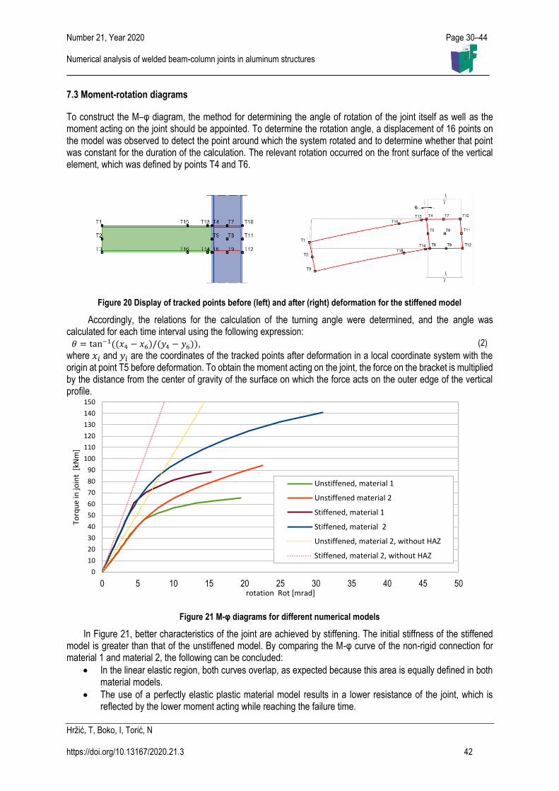
Figure 21 M-φ diagrams for different numerical models
In Figure 21, better characteristics of the joint are achieved by stiffening. The initial stiffness of the stiffened model is greater than that of the unstiffened model. By comparing the M-φ curve of the non-rigid connection for material 1 and material 2, the following can be concluded:
In the linear elastic region, both curves overlap, as expected because this area is equally defined in both material models.
The use of a perfectly elastic plastic material model results in a lower resistance of the joint, which is reflected by the lower moment acting while reaching the failure time.
0 5 10 15 20 25 30 35 40 45 50
0
10
20
30
40
50
60
70
80
90
100
110
120
130
140
150
rotation Rot [mrad]
Torq
ue
in jo
int
[kN
m]
Unstiffened, material 1
Unstiffened material 2
Stiffened, material 1
Stiffened, material 2
Unstiffened, material 2, without HAZ
Stiffened, material 2, without HAZ
Figure 20 Display of tracked points before (left) and after (right) deformation for the stiffened model

Number 21, Year 2020 Page 30–44 Numerical analysis of welded beam-column joints in aluminum structures
Hržić, T, Boko, I, Torić, N
https://doi.org/10.13167/2020.21.3 43
When the yield stress limit is exceeded in material model 1, there is a significant decrease in stiffness, and the system fails earlier.
The ductility of the joint is higher when using material model 2, the model obtained from the results of the experiments.
For both rigid joint and non-rigid joints, a numerical calculation was performed to calculate the initial stiffness in a linear elastic region, for a model in which the HAZ zone was not defined. The model is composed solely of the base material and weld. The obtained results are shown in the diagram in terms of straight, dashed lines in the moment-rotation diagrams. By analyzing these lines, as in the previous models, the stiff joint is more rigid than the unstiffened one. When compared with the curves described above, the stiffness of the models containing the HAZ zone is lower than that of the models without HAZ. This behavior is expected because the HAZ zone has lower mechanical characteristics than those of the base material, and when stresses occur in this zone, plastification occurs quickly, leading to joint failure.
8 CONCLUSION
Based on the results obtained in the previous chapters, the conclusions outlined below can be drawn. A numerical model for evaluating material model 2, that is, the material model derived from the results of the experiments, provides results that describe the actual behavior of the joint better than material model 1. From the constructed moment-rotation diagrams, despite the existence of a HAZ zone, which has less favorable characteristics than those of the base material, the stiffening of the joints in aluminum constructions improves the properties of the joint in terms of higher rigidity, resistance, and ductility.
By comparing the results obtained, the application of the material model derived from the results of the experiments results in higher ductility of the joint and higher resistance than those of the perfectly elastic plastic material model. By applying the perfectly elastic plastic material model, which is defined in the standard HRN EN 1999-1-1 [20], the obtained results are considered to be safe, and hence, the use of this material model for FEM modelling of joints in aluminum structures is only valid for structures with material in the linear elastic range. Joint behavior depends on the material model used. Therefore, the aim of future research is to conduct a sensitivity analysis of joint behavior using different material models that are available from the literature. In addition, experimental verification of this study will be useful to evaluate the methods used in this study.
Acknowledgements
This research is partially supported through project KK.01.1.1.02.0027, a project co-financed by the Croatian Government and the European Union through the European Regional Development Fund–the Competitiveness and Cohesion Operational Program.
References
[1] Scott, H. M.; Gittos, F.M. 1983: Tensile and toughness properties of arc-welded 5083 and 6082 aluminium alloys, Welding Journal Research Supplement, 62 (9), pp.243-252.
[2] Matusiak, M.; Larsen, P.K. 1999: Strength and ductility of welded connections in aluminium alloys. In: Joints in Aluminium-INALCO'98: Seventh International Conference. Woodhead Publishing, pp. 299-309.
[3] Matusiak, M.: Strength and ductility of welded structures in aluminium alloys, doctoral thesis, NTNU, Trondheim, 1999.
[4] Edlund, S.: Buckling of T-Section Beam-Columns in Aluminium with or without Transverse Welds, doctoral thesis, KTH, Stockholm, 2000
[5] Wang, T.: Modelling of Welded Thin-Walled Aluminium Structures, doctoral thesis, NTNU, Trondheim, 2006. [6] Zha, Y.; Moan, T. 2001: Ultimate strength of stiffened aluminium panels with predominantly torsional failure
modes, Thin-walled structures, 39 (8), pp. 631-648. https://doi.org/10.1016/S0263-8231(01)00027-1 [7] Sensharma, P.; Collette, M. D.; Harrington, J. 2011: Effect of welded properties on aluminum structures. Ship
Structure Committee Report 2011.
Number 21, Year 2020 Page 30–44 Numerical analysis of welded beam-column joints in aluminum structures
Hržić, T, Boko, I, Torić, N
https://doi.org/10.13167/2020.21.3 44
[8] De Matteis, G.; Mazzolani, F. M. 2006: Behaviour of welded aluminium T-stub connections: experimental analysis and interpretative models. In Structures Congress 2006: Structural Engineering and Public Safety pp. 1-14.
[9] De Matteis, G.; Mandara, A.; Mazzolani, M.F. 2000: T-stub aluminium joints: influence of behavioural parameters, Computers and Structures, 78 (1-3), pp. 311-327. https://doi.org/10.1016/S0045-7949(00)00081-X
[10] Brando, G.; Sarracco, G.; De Matteis, G. 2015: Strength of an Aluminum Column Web in Tension, Journal of Structural Engineering, 141 (7), 04014180. https://doi.org/10.1061/(ASCE)ST.1943-541X.0001138
[11] Sheppard, T. 1999: Extrusion of Aluminium Alloys, Springer US. [12] Boko, I.; Skejić, D.; Torić, N. 2017: Aluminijske konstrukcije, University of Split, Faculty of Civil Engineering,
Architecture and Geodesy. [13] Dokšanović, T.; Džeba, I.; Markulak, D. 2017: Applications of aluminium alloys in civil engineering, Technical
Gazette, 24 (5), pp. 1609-1618. https://doi.org/10.17559/TV-20151213105944 [14] Skejić, D.; Boko, I.; Torić, N.: Aluminium as a material for modern structures, Građevinar, 67 (11), pp. 1075-
1085. https://doi.org/10.14256/JCE.1395.2015 [15] HRN EN 1011-4:2001, Welding. Recommendations for welding of metallic materials - Part 4: Arc welding of
aluminium and aluminium alloys (EN 1011-4:2000), HZN,2001. [16] HRN EN 573-3:2014, Aluminium and aluminium alloys - Chemical composition and form of wrought products-
Part 3: Chemical composition and form of products, HZN, 2014 [17] HRN EN 515: 2008, Aluminium and aluminium alloys – Wrought products – Temper designation (EN
515:1993), HZN, 2008. [18] Dwight, J. 1999: Aluminium Design and Construction, E & FN Spon. [19] Dokšanović, T.; Markulak, D.; Džeba, I. 2014: State of the art review of the stability and welding of aluminium
alloy elements, Građevinar, 66 (02), pp. 115-125. https://doi.org/10.14256/JCE.932.2013 [20] HRN EN 1999-1-1: 2015, Eurokod 9, Design of aluminium structures - Part 1-1: General structural rules (EN
199-1-1: 2007+A1:2009+A2:2013), HZN, 2015. [21] Wang, T. et al. 2007: Finite element analysis of beam-to-column joints in aluminium alloy EN AW 6082 T6,
Finite Elements in Analysis and Design, 44 (1-2), pp. 1-16. https://doi.org/10.1016/j.finel.2007.08.010 [22] Blecha Gesellschaft m.b.H. Catalogue of aluminium profiles by "Blecha",
https://www.aluprofil.at/hr/standardni-profili/trazilica-profila/, Accessed 28 December 2020 [23] SpaceClaim Corporation, SpaceClaim User’s Guide, 2007. [24] ANSYS, Inc.: ANSYS Meshing User's Guide, 2013. [25] Kohnke, P.: ANSYS Theory reference, SAS IP, inc., 1999. [26] Madenci, E.; Guven, I. 2015: The Finite Element Method and Applications in Engineering Using ANSYS ®,
Springer. Please cite this article as: Hržić, T.; Boko, I.; Torić, N.: Numerical analysis of welded beam-column joints in aluminum structures, Electronic Journal of the Faculty of Civil Engineering Osijek-e-GFOS, 2020, 21, pp. 30-44, https://doi.org/10.13167/2020.21.3