nuclear medicine/pet phantom image atlas
TRANSCRIPT
Nuclear Medicine/PET Phantom Image Atlas
INTRODUCTION ............................................................................................................................. 1
GENERAL TIPS AND REMINDERS .............................................................................................. 2
PLANAR ........................................................................................................................................ 3
Uniformity ................................................................................................................................. 3
Spatial Resolution .................................................................................................................... 5
Non-traditional scanners ........................................................................................................ 6
SPECT ........................................................................................................................................... 7
Traditional scanners ............................................................................................................... 7
Non-traditional scanners ........................................................................................................ 9
Cardiac Scanner with 180o acquisition .............................................................................. 10
Small SPECT Phantom ........................................................................................................... 11
PET ............................................................................................................................................. 12
ARTIFACTS ................................................................................................................................ 15
Planar ......................................................................................................................................... 15
SPECT ......................................................................................................................................... 18
PET ............................................................................................................................................. 23

P a g e | 1
Return to Top
INTRODUCTION The links below will direct users to requirements for NM & PET Clinical and Phantom submissions. Please review carefully prior to the uploading of images and submission of the testing packets.
https://accreditationsupport.acr.org/support/solutions/articles/11000062796-accreditation-testing- overview-nuclear-medicine-and-pet
https://accreditationsupport.acr.org/support/solutions/articles/11000062797-clinical-image-testing- nuclear-medicine
https://accreditationsupport.acr.org/support/solutions/articles/11000062798-phantom-images-nuclear- medicine
https://accreditationsupport.acr.org/support/solutions/articles/11000062799-clinical-
image-testing-pet
https://accreditationsupport.acr.org/support/solutions/articles/11000062800-
phantom-testing-pet
The link below will display phantom criteria:
https://accreditationsupport.acr.org/support/solutions/articles/ 11000080933-
phantom-criteria-revised-1-6-20-
When evaluating low and high contrast, please refer to the image below.
Testing packages are based on the exams selected in the accreditation application. If you need to make correction to the testing packet, i.e., remove module or change exams; please submit a support ticket at the link below BEFORE submitting the testing packet.
https://accreditationsupport.acr.org
Emergency use:
If you are doing a type of scan less than 5 times a month or 25 times a year, YOU ARE NOT
REQUIRED TO APPLY. This also applies to Tl201, Ga67, & In111.

P a g e | 2
Return to Top
GENERAL TIPS AND REMINDERS
1. Incomplete or incorrect uploads (images and/or documentation) will be removed and sites will need to re-upload. This can slow down the review process.
2. Cell phone images, scanned paper or color photos and non-digital images (i.e., scanned
documents saved as jpg) are not acceptable as electronic clinical or phantom uploads. The
image below on the left shows a paper print scanned and uploaded as jpg. The image on
the right is the same image submitted as a “true” digital image.
3. Look for red-lettering instructions when uploading images in the ACRedit database.
4. The following images are examples only. They are not meant to show required formatting.
5. If your scanner is not capable of planar imaging, the application should reflect that by
selecting “This unit is unable to acquire planar images.”
6. If you are submitting for Cardiac only and the scanner is capable of planar imaging, do not select this option - you will be required to submit planar uniformity and planar spatial resolution if the scanner is capable of acquiring planar images
If you filled out the application incorrectly for your type of scanner, please submit a support ticket to request correction BEFORE submitting the testing packet.

P a g e | 3
Return to Top
PLANAR
Uniformity
Phantom images MUST be submitted in gray scale. Please ensure isotope and detector head is identified (if submitting more than a single head). Images should include a gray scale (see image on right below).
Planar images can be formatted using 1 on 1, 2 on 1, or 4 on 1 formats.
P a g e | 4
Return to Top
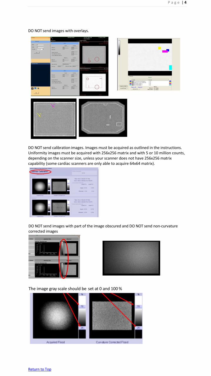
DO NOT send images with overlays.
DO NOT send calibration images. Images must be acquired as outlined in the instructions. Uniformity images must be acquired with 256x256 matrix and with 5 or 10 million counts, depending on the scanner size, unless your scanner does not have 256x256 matrix capability (some cardiac scanners are only able to acquire 64x64 matrix).
DO NOT send images with part of the image obscured and DO NOT send non-curvature corrected images
The image gray scale should be set at 0 and 100 %

P a g e | 5
Return to Top
Spatial Resolution
Planar spatial resolution – you may use 4 quadrant bar images OR the ACR phantom when submitting for Planar ONLY. If submitting bars, the smallest MUST be between 2-3 mm. If also submitting for SPECT/Cardiac modules, you must use the ACR phantom for the planar spatial resolution for Tc99m. Ensure the data form matches the images submitted. Do not fill out the data form for ACR phantom and then upload 4 quadrant bars or fill out bar sizes in the data form and then submit ACR phantom planar spatial resolution images,
Ensure settings are correct. The image on the left is the correct 600k image. The image on the right appears to be 6 million counts based on the image density.
UB bars ARE NOT approved for ACR accreditation.

P a g e | 6
Return to Top
Non-traditional scanners
Breast imaging scanners are similar to mammography scanners. The FOV is small the planar spatial resolution is only imaged using the smallest quadrant (usually 2.0 mm). The submissions will appear as seen below.
Some Digirad scanners will automatically show overexposed uniformity images on the users screen (see image below). Please check with the vendor to adjust appropriately.
Digirad planar spatial resolution images will show as seen below. Please ensure the 7.9 mm rods are fully in the FOV. (Must resolve 7.9 mm rods with high contrast and greater)

P a g e | 7
Return to Top
SPECT
Traditional scanners
Screen captures, jpgs, tif, etc., are acceptable for uniformity and spatial resolution. However, it is recommended to upload the slices as DICOM axial images. DICOM images allow reviewers to window, zoom, draw ROIs (i.e., for PET.)
The uniformity section of the phantom is at the top, above the spheres and NOT the section between rods and spheres. Include the ENTIRE SPECT volume!
Example of phantom images top to bottom. Make sure to include the summed rods with the axial SPECT slices.
The standard phantom is no longer approved for use. The smallest rods in the standard phantom are 6.4 mm (7 rods) while the deluxe phantom is 4.8 (10 rods). Please ensure you are using the correct phantom.

P a g e | 8
Return to Top
If submitting jpgs or screen captures, it’s recommended to zoom the series so the images fill each frame.
This submission in the image below should have been broken up into 2-3 pages of 9, 12 or 16 on 1 formats. These images are too small to properly evaluate. Additionally, the image below show slices that are too thin. Instructions require 6-9 mm thick slices. Images usually need to be reframed by a factor of 2 to 3 - check with your physicist if you’re not sure of the slice thickness.
Attenuation correction is required if available on the scanner. A dark rim on the axial image set below suggests the attenuation correction was not applied or applied incorrectly. Additionally, it’s recommended to check the position of the attenuation correction region (circle) around phantom. If you are unsure of the attenuation correction factor, contact your physicist or vendor applications. Some systems do not have attenuation correction or the saved system default attenuation correction may not be correct.

P a g e | 9
Return to Top
Non-traditional scanners
Digirad: The slices displayed below are too thin, but the image shows a general SPECT display that includes the summed rods image.
D-SPECT: Normal appearance of D-SPECT screen capture.
GE 530C:
This a normal appearance for this type of scanner using a small phantom. A summed image is
still required. CZT and non-planar scanners may look different than more commonly used general imaging scanners.

P a g e | 10
Return to Top
Cardiac Scanner with 180o acquisition
For a single detector camera which is only capable of rotating 180 degrees, rather than a complete 360 degrees, special caution must be exercised in the orientation of the spheres. The phantom must be positioned so that the largest sphere is at the center of the 180-degree sweep for frame 1. If a Dual head, fixed 90 degrees detector configuration that only has a 180-degree acquisition arc is being tested, the largest sphere must be positioned in the center of the leading detector for frame 1.
Failure to follow these directions may produce poor contrast in the spheres.

P a g e | 11
Return to Top
Small SPECT Phantom Example of a small phantom (see instructions for units approved to use the small phantom). Ensure the data form matches the images submitted.

P a g e | 12
Return to Top
PET Sites may still upload screen captures, jpg, png, etc., images. The ROI image will usually be a screen capture or jpg. It is recommended that the axial phantom slices be uploaded as a DICOM file with 1 cm thick slices (per the testing instructions). When images are screen captured or saved as jpgs, the windowing, zoom, etc., is fixed and reviewers cannot adjust. DICOM images allow the reviewers to adjust the windowing, zoom, and scroll through the slices. This eliminates errors of not including all of the slices, or the images are too small or are inappropriately windowed. DICOM uploads will also allow the reviewers to draw ROIs to check for errors that may occur when filling out the data form.
Example of a good phantom submission for PET – 2020 scanner:
Images from 2011 scanner:
ROIs correctly drawn (example from the website)

P a g e | 13
Return to Top
Images can be submitted as displayed above or inverted. If images uploaded are DICOM, reviewers can invert as necessary.

P a g e | 14
Return to Top
Please zoom the series so the image fills each frame. When reviewers try to zoom the screen capture, the images may become “pixely” and will return as not reviewed. The images will be cleared, the testing packet re-opened, and sites will need to re-upload the same images reformatted.
Images correctly zoomed to fill each frame.

P a g e | 15
Return to Top
Artifacts
Planar It is highly recommended to review the images with your physicist prior to submission.
Poor paper print that was scanned and submitted as a jpg. The red arrows show an artifact on the paper printout that is accentuated when scanned as jpg.
Gray scale set at 25% and 75% can adversely affect images.
Re

P a g e | 16
Return to Top
Red arrows point to artifacts

P a g e | 17
Return to Top
Non Linear artifacts

P a g e | 18
Return to Top
SPECT It is recommended to review the images with your physicist prior to submission.
Images showing poor masking and non-circular images.
Image distortion

P a g e | 19
Return to Top
Example of Bullseye ring artifact It is always recommended that a new uniformity calibration and COR be acquired prior to the phantom acquisition.

P a g e | 20
Return to Top
Color images are not acceptable. Additionally, please do not include raw data. Below is also an example of a poor color print or paper image scanned in to create a jpg for upload. This is not acceptable.

P a g e | 21
Return to Top
Non-circular image and lack of the rods section visualization resulted in failure.

P a g e | 22
Return to Top
Example below of a more moderate ring artifact also resulting in failure.

P a g e | 23
Return to Top
PET
It is recommended to review the images with your physicist prior to submission.
Images below are quite noisy and the 16mm cylinder does not appear completely circular.

P a g e | 24
Return to Top
Images should be normalized to the series, not each frame. Images 17-18 are brighter
than the rest of the series.
Poor spatial resolution displayed below. Only the largest rods are seen.