nuclear matters - lasg home page · this practical guide to nuclear matters is an expanded and...
TRANSCRIPT

NUCLEAR MATTERSA Practical Guide

�
This practical guide to Nuclear Matters is an expanded and revised version of the earlier Nuclear Weapons Stockpile Management Handbook and the Nuclear Weapons Council Handbook. Originally published in 1991 for the use of Action Officers associated with the Nuclear Weapons Council, previous editions have been modified over time to meet the needs of the larger nuclear weapons community as well as those outside the community who seek a better understanding of the subject. Since the early 1990s, the U.S. Nuclear Weapons Program has evolved significantly as a result of unilateral and bilateral arms reductions and the end of underground nuclear testing in the United States; successive editions of these books have been revised and restructured to reflect these changes.
This book is intended to be an unofficial reference that explains the history and development of the U.S. Nuclear Weapons Program as well as the current activities associated with sustaining the U.S. nuclear deterrent. It is designed to be useful, but it is neither authoritative nor directive. Please refer to the applicable statute, regulation, Department of Defense Direction/Instruction, or Department of Energy Order for definitive guidance in all areas related to the U.S. Nuclear Weapons Program.
The content of Nuclear Matters: A Practical Guide is the sole responsibility of the Office of the Deputy Assistant to the Secretary of Defense for Nuclear Matters.
Please forward substantive comments and revisions to:
Office of the Deputy Assistant to the Secretary of Defense (Nuclear Matters)
The Pentagon Room 3B884
Washington, DC 20301-3050
www.acq.osd.mil/ncbdp/nm
Foreword


���
Foreword .... .... .... .... .... .... .... .... .... .... .... .... .... .... .... .... .... .... ..i
Chapter 1: The U.S. Nuclear Weapons Program1.1 Overview .. .... .... .... .... .... .... .... .... .... .... .... .... .... .... .... .... .... .... ... 11.2 The U.S. Nuclear Weapons Program .... .... .... .... .... .... .... .... .... .... ... 11.3 History of the U.S. Nuclear Weapons Program .... .... .... .... .... .... .... ... 11.4 End of Underground Nuclear Testing.... .... .... .... .... .... .... .... .... .... ... 51.5 New Challenges . .... .... .... .... .... .... .... .... .... .... .... .... .... .... .... .... ... 7
1.5.1 Aging Warheads in an Era of No Nuclear Testing ... .... .... .... .... .... 81.5.2 Modern Safety, Security, and Control Features .. .... .... .... .... .... .... 91.5.3 Loss of Technical Expertise .. .... .... .... .... .... .... .... .... .... .... .... .. 101.5.4 Deterioration of the Nuclear Complex Infrastructure .. .... .... .... .. 101.5.5 Stockpile Quantities .. .... .... .... .... .... .... .... .... .... .... .... .... .... .. 11
1.6 Future of the U.S. Nuclear Weapons Program. .... .... .... .... .... .... .... . 11
Chapter 2: L�fe-Cycle of U.S. Nuclear Weapons2.1 Overview .. .... .... .... .... .... .... .... .... .... .... .... .... .... .... .... .... .... .... . 132.2 1953 Agreement. .... .... .... .... .... .... .... .... .... .... .... .... .... .... .... .... . 142.3 Dual-Agency Responsibility .. .... .... .... .... .... .... .... .... .... .... .... .... . 152.4 Phase 1 - Concept Study ... .... .... .... .... .... .... .... .... .... .... .... .... .... . 162.5 Phase 2 - Feasibility Study . .... .... .... .... .... .... .... .... .... .... .... .... .... . 172.6 Phase 2A - Design Definition and Cost Study . .... .... .... .... .... .... .... . 172.7 Phase 3 - Full-Scale Engineering Development .... .... .... .... .... .... .... . 182.8 Phase 4 - Production Engineering .... .... .... .... .... .... .... .... .... .... .... . 192.9 Phase 5 - First Production . .... .... .... .... .... .... .... .... .... .... .... .... .... . 192.10 Phase 6 - Quantity Production and Stockpile Maintenance
and Evaluation ... .... .... .... .... .... .... .... .... .... .... .... .... .... .... .... .... . 202.10.1 Limited-Life Components (LLCs). .... .... .... .... .... .... .... .... .... .. 212.10.2 The Phase 6.X Process .... .... .... .... .... .... .... .... .... .... .... .... .... .. 222.10.3 Phase 6.1 - Concept Assessment .... .... .... .... .... .... .... .... .... .... .. 232.10.4 Phase 6.2 - Feasibility Study and Option Down-Select .... .... .... .. 232.10.5 Phase 6.2A - Design Definition and Cost Study .... .... .... .... .... .. 252.10.6 Phase 6.3 - Development Engineering .... .... .... .... .... .... .... .... .. 25
Table of Contents

�v
Nuclear Matters: A Practical Guide20
08
2.10.7 Phase 6.4 - Production Engineering ... .... .... .... .... .... .... .... .... .. 262.10.8 Phase 6.5 - First Production .... .... .... .... .... .... .... .... .... .... .... .. 272.10.9 Phase 6.6 - Full-Scale Production .. .... .... .... .... .... .... .... .... .... .. 28
2.11 Phase 7 - Retirement and Dismantlement .. .... .... .... .... .... .... .... .... . 28
Chapter 3: Nuclear Weapons Program Force Structure3.1 Overview .. .... .... .... .... .... .... .... .... .... .... .... .... .... .... .... .... .... .... . 293.2 U.S. Defense Objectives .... .... .... .... .... .... .... .... .... .... .... .... .... .... . 293.3 Employment of Nuclear Weapons .... .... .... .... .... .... .... .... .... .... .... . 313.4 U.S. Nuclear Stockpile Composition .... .... .... .... .... .... .... .... .... .... . 333.5 Nuclear Stockpile Quantities .. .... .... .... .... .... .... .... .... .... .... .... .... . 343.6 U.S. Nuclear Weapons Delivery Systems .... .... .... .... .... .... .... .... .... . 34
3.6.1 Bombers .... .... .... .... .... .... .... .... .... .... .... .... .... .... .... .... .... .. 383.6.2 Submarines. .... .... .... .... .... .... .... .... .... .... .... .... .... .... .... .... .. 393.6.3 ICBMs . .... .... .... .... .... .... .... .... .... .... .... .... .... .... .... .... .... .. 413.6.4 Dual Capable Aircraft (DCA) .. .... .... .... .... .... .... .... .... .... .... .. 41
3.7 DoD Strategic and Non-Strategic Operational Bases . .... .... .... .... .... . 42
Chapter 4: Nuclear Weapons Program Infrastructure4.1 Overview .. .... .... .... .... .... .... .... .... .... .... .... .... .... .... .... .... .... .... . 45
4.1.1 Complex Transformation .... .... .... .... .... .... .... .... .... .... .... .... .. 464.1.2 The U.S. Nuclear Weapons Complex . .... .... .... .... .... .... .... .... .. 46
4.2 Stockpile Stewardship Program ... .... .... .... .... .... .... .... .... .... .... .... . 514.2.1 The Transition to a Science-Based Substitute .... .... .... .... .... .... .. 524.2.2 Stockpile Stewardship Program Elements .... .... .... .... .... .... .... .. 53
Chapter 5: Nuclear Weapons Surety5.1 Overview .. .... .... .... .... .... .... .... .... .... .... .... .... .... .... .... .... .... .... . 655.2 Dual Agency Surety Responsibilities. .... .... .... .... .... .... .... .... .... .... . 655.3 Nuclear Weapons System Safety .. .... .... .... .... .... .... .... .... .... .... .... . 65
5.3.1 The DoD and DOE Safety Programs .... .... .... .... .... .... .... .... .. 665.3.2 Nuclear Weapon Design Safety .... .... .... .... .... .... .... .... .... .... .. 66
5.4 Nuclear Weapons Security. .... .... .... .... .... .... .... .... .... .... .... .... .... . 725.4.1 DoD Nuclear Weapons Security Standard.... .... .... .... .... .... .... .. 725.4.2 DOE Safeguards and Security .. .... .... .... .... .... .... .... .... .... .... .. 735.4.3 DoD and DOE Personnel Security .... .... .... .... .... .... .... .... .... .. 745.4.4 Procedural Security.... .... .... .... .... .... .... .... .... .... .... .... .... .... .. 755.4.5 DoD and DOE Security Program Authorities ... .... .... .... .... .... .. 755.4.6 Programs of Cooperation ... .... .... .... .... .... .... .... .... .... .... .... .. 76

v
Table of Contents
5.5 Nuclear Command and Control (NC2) and Use Control .... .... .... .... . 765.5.1 Nuclear Command and Control (NC2)... .... .... .... .... .... .... .... .. 775.5.2 Use Control Features. .... .... .... .... .... .... .... .... .... .... .... .... .... .. 775.5.3 The DoD Control Program .... .... .... .... .... .... .... .... .... .... .... .. 795.5.4 The NNSA Control Program ... .... .... .... .... .... .... .... .... .... .... .. 79
Chapter 6: Qual�ty Assurance and Non-Nuclear Test�ng6.1 Overview .. .... .... .... .... .... .... .... .... .... .... .... .... .... .... .... .... .... .... . 816.2 The Evolution of Quality Assurance and Sampling.... .... .... .... .... .... . 826.3 Surveillance Transformation Project (STP) . .... .... .... .... .... .... .... .... . 846.4 Stockpile Laboratory Testing (SLT) .. .... .... .... .... .... .... .... .... .... .... . 846.5 Stockpile Flight Testing (SFT) .... .... .... .... .... .... .... .... .... .... .... .... . 856.6 Safety Validation and Reliability Estimates . .... .... .... .... .... .... .... .... . 86
Chapter 7: The Nuclear Weapons Counc�l and Annual Reports7.1 Overview .. .... .... .... .... .... .... .... .... .... .... .... .... .... .... .... .... .... .... . 877.2 NWC History .... .... .... .... .... .... .... .... .... .... .... .... .... .... .... .... .... . 87
7.2.1 The Military Liaison Committee (MLC) . .... .... .... .... .... .... .... .. 887.2.2 The Blue Ribbon Task Group on Nuclear Weapons
Program Management .... .... .... .... .... .... .... .... .... .... .... .... .... .. 897.3 The NWC Today .... .... .... .... .... .... .... .... .... .... .... .... .... .... .... .... . 907.4 NWC Organization and Members ... .... .... .... .... .... .... .... .... .... .... . 917.5 NWC Responsibilities and Activities .... .... .... .... .... .... .... .... .... .... . 927.6 NWC Procedures & Processes .... .... .... .... .... .... .... .... .... .... .... .... . 937.7 NWC Subordinate Organizations .... .... .... .... .... .... .... .... .... .... .... . 94
7.7.1 The Nuclear Weapons Council Standing and Safety Committee. .... .... .... .... .... .... .... .... .... .... .... .... .... .... .. 96
7.7.2 The Compartmented Advisory Committee... .... .... .... .... .... .... 1007.7.3 The Transformation Coordinating Committee .. .... .... .... .... .... 1027.7.4 The NWC Action Officers Group . .... .... .... .... .... .... .... .... .... 1037.7.5 The Nuclear Weapons Council Staff ... .... .... .... .... .... .... .... .... 104
7.8 NWC Annual Reports . .... .... .... .... .... .... .... .... .... .... .... .... .... .... 1067.8.1 Nuclear Weapons Stockpile Memorandum and
Requirements Planning Document (NWSM/RPD) .... .... .... .... 1067.8.2 NWC Report on Stockpile Assessments (ROSA).... .... .... .... .... 1087.8.3 NWC Chairman’s Annual Report to Congress (CARC) ... .... .... 1107.8.4 Joint Surety Report (JSR).... .... .... .... .... .... .... .... .... .... .... .... 111

v�
Nuclear Matters: A Practical Guide20
08
Chapter 8: The NCCS Comm�ttee of Pr�nc�pals8.1 Overview .. .... .... .... .... .... .... .... .... .... .... .... .... .... .... .... .... .... .... 1138.2 National Security Presidential Directive 28 (NSPD-28) . .... .... .... .... 1138.3 Nuclear Command and Control System (NCCS) .... .... .... .... .... .... 1148.4 The NCCS CoP . .... .... .... .... .... .... .... .... .... .... .... .... .... .... .... .... 114
8.4.1 NCCS CoP History .. .... .... .... .... .... .... .... .... .... .... .... .... .... 1158.4.2 NCCS CoP Responsibilities .... .... .... .... .... .... .... .... .... .... .... 1158.4.3 The NCCS CoP Deputies Committee .... .... .... .... .... .... .... .... 1168.4.4 Nuclear Weapons Accident Response Subcommittee
(NWARS) .. .... .... .... .... .... .... .... .... .... .... .... .... .... .... .... .... 1168.4.5 NCCS CoP Action Officers Group .... .... .... .... .... .... .... .... .... 116
8.5 DoD-Specific NSPD-28 Compliance Actions . .... .... .... .... .... .... .... 1178.6 DoD NSPD-28 Implementation Senior Management Oversight .. .... 117
Append�x A: Bas�c Nuclear Phys�csA.1 Overview .. .... .... .... .... .... .... .... .... .... .... .... .... .... .... .... .... .... .... 121A.2 Atomic Structure .... .... .... .... .... .... .... .... .... .... .... .... .... .... .... .... 121A.3 Radioactive Decay... .... .... .... .... .... .... .... .... .... .... .... .... .... .... .... 124A.4 Nuclear Reactions ... .... .... .... .... .... .... .... .... .... .... .... .... .... .... .... 125
A.4.1 Fission... .... .... .... .... .... .... .... .... .... .... .... .... .... .... .... .... .... 125A.4.2 Fusion ... .... .... .... .... .... .... .... .... .... .... .... .... .... .... .... .... .... 129
A.5 Basic Weapon Designs .. .... .... .... .... .... .... .... .... .... .... .... .... .... .... 129A.5.1 Achieving Supercritical Mass .... .... .... .... .... .... .... .... .... .... .... 130A.5.2 Gun Assembly Weapons. .... .... .... .... .... .... .... .... .... .... .... .... 131A.5.3 Implosion Assembly Weapons .. .... .... .... .... .... .... .... .... .... .... 131A.5.4 Boosted Weapons . .... .... .... .... .... .... .... .... .... .... .... .... .... .... 132A.5.5 Staged Weapons ... .... .... .... .... .... .... .... .... .... .... .... .... .... .... 133A.5.6 Proliferation Considerations .... .... .... .... .... .... .... .... .... .... .... 133
Append�x B: The Effects of Nuclear WeaponsB.1 Overview .. .... .... .... .... .... .... .... .... .... .... .... .... .... .... .... .... .... .... 135B.2 General Concepts and Terms .. .... .... .... .... .... .... .... .... .... .... .... .... 137B.3 The Nuclear Fireball .... .... .... .... .... .... .... .... .... .... .... .... .... .... .... 138B.4 Thermal Radiation .. .... .... .... .... .... .... .... .... .... .... .... .... .... .... .... 139
B.4.1 Thermal Radiation Damage & Injury. .... .... .... .... .... .... .... .... 139B.4.2 Thermal Radiation Employment Factors . .... .... .... .... .... .... .... 140B.4.3 Thermal Radiation Protection .. .... .... .... .... .... .... .... .... .... .... 141
B.5 Air Blast ... .... .... .... .... .... .... .... .... .... .... .... .... .... .... .... .... .... .... 141B.5.1 Air Blast Damage & Injury . .... .... .... .... .... .... .... .... .... .... .... 142

v��
Table of Contents
B.5.2 Air Blast Employment Factors .. .... .... .... .... .... .... .... .... .... .... 143B.5.3 Air Blast Protection ... .... .... .... .... .... .... .... .... .... .... .... .... .... 143
B.6 Ground Shock.... .... .... .... .... .... .... .... .... .... .... .... .... .... .... .... .... 144B.6.1 Ground Shock Damage & Injury .. .... .... .... .... .... .... .... .... .... 144B.6.2 Ground Shock Employment Factors... .... .... .... .... .... .... .... .... 144B.6.3 Ground Shock Protection.... .... .... .... .... .... .... .... .... .... .... .... 145
B.7 Surface Crater .... .... .... .... .... .... .... .... .... .... .... .... .... .... .... .... .... 145B.7.1 Surface Crater Damage & Injury... .... .... .... .... .... .... .... .... .... 146B.7.2 Surface Crater Employment Factors ... .... .... .... .... .... .... .... .... 146B.7.3 Surface Crater Protection .... .... .... .... .... .... .... .... .... .... .... .... 146
B.8 Underwater Shock... .... .... .... .... .... .... .... .... .... .... .... .... .... .... .... 146B.8.1 Underwater Shock Damage & Injury . .... .... .... .... .... .... .... .... 147B.8.2 Underwater Shock Employment Factors .. .... .... .... .... .... .... .... 147B.8.3 Underwater Shock Protection... .... .... .... .... .... .... .... .... .... .... 147
B.9 Initial Nuclear Radiation... .... .... .... .... .... .... .... .... .... .... .... .... .... 147B.9.1 Initial Nuclear Radiation Damage & Injury . .... .... .... .... .... .... 148B.9.2 Initial Nuclear Radiation Employment Factors .. .... .... .... .... .... 149B.9.3 Initial Nuclear Radiation Protection... .... .... .... .... .... .... .... .... 150
B.10 Residual Nuclear Radiation .... .... .... .... .... .... .... .... .... .... .... .... .... 150B.10.1 Residual Nuclear Radiation Damage & Injury .. .... .... .... .... .... 151B.10.2 Residual Nuclear Radiation Employment Factors... .... .... .... .... 152B.10.3 Residual Nuclear Radiation Protection .... .... .... .... .... .... .... .... 152
B.11 Biological Effects of Ionizing Radiation. .... .... .... .... .... .... .... .... .... 153B.11.1 Ionizing Radiation Damage & Injury. .... .... .... .... .... .... .... .... 153B.11.2 Ionizing Radiation Protection... .... .... .... .... .... .... .... .... .... .... 154
B.12 ElectroMagnetic Pulse (EMP) .... .... .... .... .... .... .... .... .... .... .... .... 154B.12.1 EMP Damage & Injury .. .... .... .... .... .... .... .... .... .... .... .... .... 155B.12.2 EMP Employment Factors .. .... .... .... .... .... .... .... .... .... .... .... 155B.12.3 EMP Protection ... .... .... .... .... .... .... .... .... .... .... .... .... .... .... 156
B.13 Transient Radiation Effects on Electronics (TREE) ... .... .... .... .... .... 156B.13.1 TREE Damage & Injury .... .... .... .... .... .... .... .... .... .... .... .... 156B.13.2 TREE Employment Factors .... .... .... .... .... .... .... .... .... .... .... 157B.13.3 TREE Protection . .... .... .... .... .... .... .... .... .... .... .... .... .... .... 157
B.14 Black-Out .... .... .... .... .... .... .... .... .... .... .... .... .... .... .... .... .... .... 157B.14.1 Black-Out Damage & Injury.... .... .... .... .... .... .... .... .... .... .... 157B.14.2 Black-Out Employment Factors .... .... .... .... .... .... .... .... .... .... 158B.14.3 Black-Out Protection .... .... .... .... .... .... .... .... .... .... .... .... .... 158
Append�x C: Nuclear Weapons Effects Surv�vab�l�ty and Test�ngC.1 Overview .... .... .... .... .... .... .... .... .... .... .... .... .... .... .... .... .... .... .... 159C.2 Nuclear Weapons Effects Survivability... .... .... .... .... .... .... .... .... .... 161

v���
Nuclear Matters: A Practical Guide20
08
C.2.1 Nuclear Weapons Effects on Military Systems ... .... .... .... .... .... 161C.2.2 Nuclear Weapons Effects on Personnel .... .... .... .... .... .... .... .... 164C.2.3 Nuclear Weapons Effects Survivability Measures .... .... .... .... .... 164
C.3 Nuclear Weapons System Survivability .. .... .... .... .... .... .... .... .... .... 166C.3.1 Nuclear Force Survivability . .... .... .... .... .... .... .... .... .... .... .... 167C.3.2 Nuclear Command and Control Survivability ... .... .... .... .... .... 167C.3.3 Missile Silos .... .... .... .... .... .... .... .... .... .... .... .... .... .... .... .... 167C.3.4 Containers.. .... .... .... .... .... .... .... .... .... .... .... .... .... .... .... .... 167C.3.5 Weapons Storage Vault .. .... .... .... .... .... .... .... .... .... .... .... .... 168
C.4 Tests and Evaluation .... .... .... .... .... .... .... .... .... .... .... .... .... .... .... 168C.4.1 Testing .. .... .... .... .... .... .... .... .... .... .... .... .... .... .... .... .... .... 168C.4.2 X-ray Effects Testing .. .... .... .... .... .... .... .... .... .... .... .... .... .... 169C.4.3 Gamma Dose-Rate Effects Testing. .... .... .... .... .... .... .... .... .... 171C.4.4 Total-Dose Effects Testing ... .... .... .... .... .... .... .... .... .... .... .... 172C.4.5 Neutron Effects Testing .. .... .... .... .... .... .... .... .... .... .... .... .... 172C.4.6 EMP Effects Testing .. .... .... .... .... .... .... .... .... .... .... .... .... .... 172C.4.7 Air-Blast Effects Testing .. .... .... .... .... .... .... .... .... .... .... .... .... 173C.4.8 Thermal Radiation Effects Testing . .... .... .... .... .... .... .... .... .... 173C.4.9 Shock Testing .. .... .... .... .... .... .... .... .... .... .... .... .... .... .... .... 174
Append�x D: Underground Nuclear Test�ngD.1 Overview .. .... .... .... .... .... .... .... .... .... .... .... .... .... .... .... .... .... .... 175D.2 The Early Years of the U.S. Nuclear Testing Program. .... .... .... .... .... 175D.3 The Transition to Underground Nuclear Testing (UGT) .... .... .... .... 177D.4 The Transition to 3-D Codes .. .... .... .... .... .... .... .... .... .... .... .... .... 181
Append�x E: Nuclear Weapons Acc�dent ResponseE.1 Overview .. .... .... .... .... .... .... .... .... .... .... .... .... .... .... .... .... .... .... 183E.2 National Level Response Entities and Responsibilities .... .... .... .... .... 184
E.2.1 Interagency – The NCCS Committee of Principals (CoP) .... .... 185E.2.2 Department of Homeland Security .... .... .... .... .... .... .... .... .... 185E.2.3 Department of State .. .... .... .... .... .... .... .... .... .... .... .... .... .... 187E.2.4 Department of Defense .. .... .... .... .... .... .... .... .... .... .... .... .... 188
E.3 DoD Response ... .... .... .... .... .... .... .... .... .... .... .... .... .... .... .... .... 188E.3.1 DoD Nuclear Weapons Accident Guidance .. .... .... .... .... .... .... 188E.3.2 Accident Notification .... .... .... .... .... .... .... .... .... .... .... .... .... 189E.3.3 DoD Response Forces .... .... .... .... .... .... .... .... .... .... .... .... .... 190
E.4 Interagency Response ... .... .... .... .... .... .... .... .... .... .... .... .... .... .... 193E.4.1 Department of Energy.... .... .... .... .... .... .... .... .... .... .... .... .... 193E.4.2 Department of Homeland Security .... .... .... .... .... .... .... .... .... 195E.4.3 Department of State .. .... .... .... .... .... .... .... .... .... .... .... .... .... 195
�x
Table of Contents
E.4.4 Department of Justice .... .... .... .... .... .... .... .... .... .... .... .... .... 196E.4.5 Other Cooperating Agencies .... .... .... .... .... .... .... .... .... .... .... 196
E.5 Training and Exercise Program .... .... .... .... .... .... .... .... .... .... .... .... 197E.5.1 Management ... .... .... .... .... .... .... .... .... .... .... .... .... .... .... .... 197E.5.2 Exercises .... .... .... .... .... .... .... .... .... .... .... .... .... .... .... .... .... 197E.5.3 Exercise Schedule . .... .... .... .... .... .... .... .... .... .... .... .... .... .... 198
Append�x F: ClassificationF.1 Overview .. .... .... .... .... .... .... .... .... .... .... .... .... .... .... .... .... .... .... 199F.2 Information Classification . .... .... .... .... .... .... .... .... .... .... .... .... .... 199
F.2.1 National Security Information .. .... .... .... .... .... .... .... .... .... .... 199F.2.2 Atomic Energy (Nuclear) Information .... .... .... .... .... .... .... .... 200
F.3 Classifying Documents. .... .... .... .... .... .... .... .... .... .... .... .... .... .... 203F.3.1 Original Classification Authority... .... .... .... .... .... .... .... .... .... 204F.3.2 Derivative Classification Authority .... .... .... .... .... .... .... .... .... 204
F.4 Security Clearances.. .... .... .... .... .... .... .... .... .... .... .... .... .... .... .... 204F.4.1 Department of Defense Security Clearance Levels .. .... .... .... .... 205F.4.2 Department of Energy Security Clearance Levels.... .... .... .... .... 205F.4.3 Equating the Two Classification Systems . .... .... .... .... .... .... .... 205
F.5 Accessing Classified Information . .... .... .... .... .... .... .... .... .... .... .... 205F.6 Marking Classified Documents .. .... .... .... .... .... .... .... .... .... .... .... 206
F.6.1 Originally Classified Documents ... .... .... .... .... .... .... .... .... .... 207F.6.2 Derivatively Classified Documents .... .... .... .... .... .... .... .... .... 208F.6.3 Marking Restricted Data and Formerly Restricted
Data Documents .. .... .... .... .... .... .... .... .... .... .... .... .... .... .... 210F.7 For Official Use Only and Unclassified Controlled
Nuclear Information .... .... .... .... .... .... .... .... .... .... .... .... .... .... .... 210
Append�x G: Programm�ng, Plann�ng, and Budget�ng Overv�ewG.1 Overview .. .... .... .... .... .... .... .... .... .... .... .... .... .... .... .... .... .... .... 213G.2 The Role of the NWC in the Budget Process... .... .... .... .... .... .... .... 213G.3 The Federal Budget . .... .... .... .... .... .... .... .... .... .... .... .... .... .... .... 213
G.3.1 The President’s Budget.... .... .... .... .... .... .... .... .... .... .... .... .... 215G.3.2 Congressional Budget Resolution .. .... .... .... .... .... .... .... .... .... 216G.3.3 Authorization .. .... .... .... .... .... .... .... .... .... .... .... .... .... .... .... 217G.3.4 Appropriations .... .... .... .... .... .... .... .... .... .... .... .... .... .... .... 218G.3.5 Continuing Resolution... .... .... .... .... .... .... .... .... .... .... .... .... 218
G.4 The DoD and the NNSA Role in the Budget Process .... .... .... .... .... 220G.4.1 Department of Defense PPBS .. .... .... .... .... .... .... .... .... .... .... 220G.4.2 National Nuclear Security Administration PPBE.... .... .... .... .... 223

x
Nuclear Matters: A Practical Guide20
08
Append�x H: Glossary .... .... .... .... .... .... .... .... .... .... .... .... .... .... .... ....225
Append�x I: Acronym L�st ... .... .... .... .... .... .... .... .... .... .... .... .... .... ....237
Append�x J: Reference L�st . .... .... .... .... .... .... .... .... .... .... .... .... .... ....249
Append�x K: Index .. .... .... .... .... .... .... .... .... .... .... .... .... .... .... .... .... ....255

1
1.1 OverviewNuclear Matters: A Practical Guide provides an introduction to the U.S. Nuclear Weapons Program. It is designed for individuals who have a need to understand these matters and is intended to explain the various elements that constitute the Nuclear Weapons Program.
This reference book is unofficial. It was designed to be useful, but is neither authoritative or directive. The purpose of this book is to familiarize readers with concepts and terms associated with the U.S. Nuclear Weapons Program1.
1.2 The U.S. Nuclear Weapons Program The U.S. Nuclear Weapons Program is, first and foremost, a deterrent that minimizes the possibility that the U.S. will be attacked by nuclear weapons or other WMD.
The U.S. Nuclear Weapons Program represents the totality of all activities, processes, and procedures associated with the design, development, production, fielding, maintenance, repair, storage, transportation, physical security, employment, and, finally, dismantlement, disposal, and replacement of the nuclear weapons in the U.S. stockpile. The U.S. Nuclear Weapons Program also includes the various organizations and key offices within the Administration and the Congress that are a part of the approval and funding process. Finally, the U.S. Nuclear Weapons Program encompasses the infrastructure and resources—human and material—necessary to support the U.S. policy of deterrence.
1.3 History of the U.S. Nuclear Weapons ProgramThe nuclear weapons of the United States have constituted an essential element of the U.S. military capability since their initial development. The potential to harness nuclear energy for military use was first described in a letter signed by Albert Einstein (Figure 1.1) to President Franklin D. Roosevelt in August 1939. The letter described the possibility of setting up a nuclear chain reaction in a large mass of uranium—a phenomenon that would lead to the construction of bombs—and concluded with the ominous statement that experimental work
1 The information in this book is current as of October 2007.
Chapter 1The U.S. Nuclear
Weapons Program

2
Nuclear Matters: A Practical Guide20
08
was being carried out in Berlin. Einstein’s assertion that a device employing this principle would be too heavy to be carried by an aircraft gave some comfort, but this was short lived. In early 1940, Otto Frisch and Rudolph Peierls, working at Birmingham University in England, concluded that, if the fissile isotope U-235 could be separated from natural uranium, only about one pound would be needed for a bomb of huge destructive capacity. This proposition was endorsed by the government-appointed MAUD Committee in 1941, and shortly after, Prime Minister Winston Churchill
authorized work to begin on Britain’s atomic bomb project, codenamed Tube Alloys.
The first MAUD Report was sent from Britain to the U.S. in March 1941, but no comment was received from the U.S. A member of the MAUD Committee flew to the U.S. in August 1941 in a bomber to discuss the findings and to convince the U.S. that it should take the work of Frisch and Peierls very seriously. The National Academy of Sciences then proposed an all-out effort to build nuclear weapons. In a meeting on October 9, 1941, President Roosevelt was impressed with the need for an accelerated program, and by November had authorized the recommended “all-out” effort. A new policy committee, the Top Policy Group, was created to inform the President of developments in the program. The first meeting of the group took place on December 6, 1941, one day before the Japanese attack on Pearl Harbor and the entrance of the United States into World War II.
Eventually, the U.S. established the “Manhattan Project,” whose goal was to produce nuclear bombs in time to affect the outcome of WWII. In 1943, as outlined in the Quebec Agreement between the United States and the United Kingdom, the team of scientists working on the British project was transferred to the Manhattan Project to work collaboratively with their U.S. counterparts.
On July 16, 1945, the United States detonated its first nuclear explosive device called “the gadget” at the Trinity Site, which is located within the current White Sands Missile Range, near the town of Alamagordo, New Mexico. Twenty-one days later, on August 6, with President Harry S. Truman’s authorization, a specially-equipped B-29 bomber named the Enola Gay (Figure 1.2) dropped a nuclear bomb, Little Boy, on Hiroshima, Japan.
Figure 1.1 Albert Einstein

3
The U.S. Nuclear Weapons Program1c
ha
pter
Soon after Hiroshima was attacked, President Truman called for Japan’s surrender. With no response from the Japanese after three days, on August 9, another B-29 bomber (named Bockscar, Figure 1.3) dropped a second U.S. atomic weapon, Fat Man (Figure 1.4) on Nagasaki.
On August 14, 1945, Japan surrendered. The use of nuclear weapons had shortened the war and reduced the number of potential casualties on both sides by precluding a U.S. land invasion of Japan. The atomic bombs dropped on Hiroshima and Nagasaki remain the only nuclear weapons ever used in combat. Their use permanently altered the global balance of power.
The U.S. enjoyed a nuclear monopoly until August 29, 1949 when the Soviet Union conducted its first nuclear test. Within a relatively short time after the end of World War II, the Soviet Union was recognized as a potential adversary. This geostrategic consideration, and the Soviet Union’s development of a nuclear weapons capability, caused the U.S. to give a high priority to the quantity production of nuclear weapons.2 By the early 1950s, the United States and the Soviet Union had both developed the more powerful hydrogen,
2 All nuclear weapons in the current U.S. stockpile are designated either as a warhead, delivered by a missile (e.g., the W87 and the W76), or a gravity bomb, dropped from an aircraft (e.g., the B83 and the B61). The distinction between a warhead and a bomb is an important one at the engineering level because the design, engineering, and component production responsibilities between the military service and the DOE design laboratories may be different for a “W” versus a “B” weapon. However, at the national level, the stockpile plan and other programmatic actions must comply with approved treaties, current legislation, and national policy directives, most of which use the term warhead to mean all nuclear weapons, including Ws and Bs. In this book the term warhead is used to denote individual weapons without distinguishing between “W” or “B” designators, and the term warhead-type denotes a population of weapons with the same design. The terms weapon and warhead are used interchangeably in this book.
Figure 1.2 Enola Gay
Figure 1.4 Fat Man
Figure 1.3 Bockscar

4
Nuclear Matters: A Practical Guide20
08
or thermonuclear, bomb. The United Kingdom, having resumed its nuclear weapons program in 1947, successfully tested an atomic bomb in 1952. Both the U.S. and the Soviet Union increased their stockpile quantities until each possessed nuclear weapons in sufficient quantities to achieve a “secure, second-strike capability,” so that both sides would be capable of massive retaliation even after absorbing an all-out first strike. In this way, the United States and the Soviet Union were “certain” of Mutually Assured Destruction (MAD), which provided deterrence for both nations.
For the first decade or so of the nuclear era, the U.S. Nuclear Weapons Program was focused on producing sufficient nuclear material to build enough weapons to support a nuclear capability for almost every type of available military delivery system. This was considered essential because of the possibility of Cold War escalation. Throughout the late 1950s, the United States was committed to increasing nuclear weapons quantities to enhance flexibility in the types of nuclear-capable military delivery vehicles.
By 1961, the U.S. nuclear weapons stockpile had grown to more than 20,000 warheads. Most of these warheads had relatively low yields and were for short-range, non-strategic (then called “tactical”) systems. At the time, many weapons were forward deployed within the territory of U.S. allies in the North Atlantic Treaty Organization (NATO).
Beginning in the early 1960s, the U.S. shifted its priority from quantity to quality. From about 1960 until 1992, the U.S. Nuclear Weapons Program was characterized by a continuous cycle of “modernization” programs that included building and subsequently replacing the weapons in the U.S. nuclear stockpile with newer, more modern designs. In addition to warheads that were simpler3 for the military operator, modern characteristics included greater yield, smaller size4, better employment characteristics5, and more modern safety, security, and control features. A key part of this process was the use of nuclear testing to refine new designs in the development process, to test the yield of weapons
3 As a function of simplicity, the United States moved away from warheads requiring in-flight-insertion (IFI) of the nuclear component, to warheads that were self-contained “sealed-pit” devices, (“wooden rounds”), without requiring the military operator to insert components, or “build” the warhead. While these warheads may have been more complex internally, this was transparent to the operator, and the pre-fire procedures were much simpler.
4 Smaller warhead size allowed strategic missiles to carry a larger number of re-entry bodies/vehicles, and made nuclear capability possible for a greater number of delivery methods, including nuclear weapons being fired by cannon artillery or being human-portable.
5 Some of the features that provided increased operational capability included selectable yields, better fuzing (for a more accurate height of burst), increased range (for cannon-fired warheads), and shorter response times.

5
The U.S. Nuclear Weapons Program1c
ha
pter
within a year after fielding, and to define or repair certain types of technical problems related to nuclear components in weapons that were already fielded.
These modernization programs were achieved through continuous research and development efforts as well as the production of new warheads to replace aging and less sophisticated weapons, usually after the older warheads had been fielded for a period of 15-20 years. In addition, the U.S. utilized a complementary combination of non-nuclear and nuclear testing to refine designs in the development stage, certify weapon designs and production processes, validate safety, estimate reliability, detect defects, and confirm effective repairs.
1.4 End of Underground Nuclear TestingIn 1992, in anticipation of a potential comprehensive test ban treaty, the U.S. voluntarily suspended its program of Underground Nuclear Testing (UGT). The 1992 legislation that ended U.S. nuclear testing had several key elements, including a provision for 15 additional nuclear tests to be conducted by the end of September 1996 for the primary purpose of applying three modern safety features to those warheads planned for retention in the reduced stockpile under the proposed Strategic Arms Reduction Treaty (START) II.6 With a limit of 15 tests within less than four years, there was no technically credible way (at the time) to certify design modifications that would incorporate any of the desired safety features into existing warhead-types. Therefore, the legislation was deemed too restrictive to achieve the objective of improving the safety of those warhead-types lacking all of the available safety enhancement elements.7 The moratorium on UGT also resulted in suspending production of weapons with new, untested designs including those with newer safety improvements beyond those specified in the legislation. This created a shift toward a second paradigm, away from modernization and production (a cycle of newer-design warheads replacing older warheads) to a new strategy of retaining previously produced warheads indefinitely, without nuclear testing, and with no plans to replace the weapons.
In response to these new circumstances, the FY 1994 National Defense Authorization Act (P.L. 103-160), called on the Secretary of Energy to “establish a stewardship program to ensure the preservation of the core intellectual
6 Public Law 102-377, the FY93 Energy and Water Development Appropriations Act, specified three features as the desired safety features for all U.S. weapons: Enhanced Nuclear Detonation Safety (ENDS), Insensitive High Explosive (IHE), and Fire-Resistant Pit (FRP).
7 The 1992 legislation also stated that if, after September 30, 1996, any other nation conducted a nuclear test, the restriction would be eliminated. Since October 1992, several nations have conducted nuclear tests. The current restriction is one of policy, not of law.

6
Nuclear Matters: A Practical Guide20
08
and technical competencies of the United States in nuclear weapons.” In the absence of nuclear testing, the Stockpile Stewardship Program was directed to: 1) support a focused, multifaceted program to increase the understanding of the enduring stockpile; 2) predict, detect, and evaluate potential problems due to the aging of the stockpile; 3) refurbish and remanufacture weapons and components, as required; and 4) maintain the science and engineering institutions needed to support the nation’s nuclear deterrent, now and in the future. This “science-based” approach, which has served as a substitute for nuclear testing since 1992, has developed and matured and now includes computer simulations, experiments, and previous nuclear test data (combined with the judgment of experienced scientists and engineers). See Chapter 4, Nuclear Weapons Program Infrastructure, for a more complete description of this science-based approach.
Since early 1993 the U.S. Nuclear Weapons Program has been essentially “stuck” in a continuous loop that represented only a small segment of what was previously a full cycle of perpetual production and replacement. During this time, the truncated process consisted primarily of activities associated with the continuous assessment, maintenance/repair, and refurbishment of the weapons. See Chapter 2, Life-Cycle of U.S. Nuclear Weapons, for a detailed discussion of the nuclear weapons life-cycle process.
As a “technological hedge” against the catastrophic failure of a warhead-type for which there would no longer be a planned replacement weapon, the stockpile plan (the annually-updated document signed by the President that authorizes modifications in stockpile quantities and composition) was modified to include a new category of inactive warheads for reliability replacement. Prior to the UGT moratorium and the suspension of new production, these weapons would have been retired from the stockpile, dismantled, and disposed of. Under the new plan, if one warhead-type developed a catastrophic problem that affected all warheads of that type (and could not be corrected because of the inability to conduct UGT), another warhead-type could be re-activated as a replacement.
Because the U.S. suspended both production of new weapons as well as underground nuclear testing by 1992, confidence in the effectiveness of all U.S. nuclear weapons could no longer be founded on the perpetual modernization and upgrade of the warhead-types in the stockpile. Instead, the U.S. nuclear program relied on a non-nuclear Quality Assurance and Reliability Testing (QART) program to validate safety, estimate reliability, and detect component problems for each warhead-type. See Chapter 6, Quality Assurance and Non-Nuclear Testing, for details of the QART program.
Most of the warheads in the current U.S. nuclear weapons stockpile were designed and fielded to meet Cold War requirements and have been retained

7
The U.S. Nuclear Weapons Program1c
ha
pter
well beyond their original programmed life-span. U.S. leaders are reassessing the size and structure of the stockpile as a part of a transition to the potential development and production of a new warhead design. However, unlike previous development programs, this will be accomplished without nuclear testing.
It is the policy of the United States to achieve an effective strategic deterrent at the lowest level of nuclear weapons consistent with national security and commitments and obligations to U.S. allies. In 2001, the President directed that the United States reduce the number of operationally deployed strategic nuclear weapons from about 6,000 to 1,700-2,200 by 2012—a two-thirds reduction. Corresponding reductions in the nuclear stockpile will result in the lowest stockpile quantities since the Eisenhower Administration.
Several factors have permitted these dramatic reductions from the Cold War nuclear arsenal built and maintained from the 1950s to the 1990s. For several decades, the Soviet Union represented a large, intractable, ideologically motivated adversary; its fall has allowed the U.S. to reassess its nuclear force requirements. In 2001, the President also directed the transition to a new set of military capabilities more appropriate for credible deterrence in the 21st Century. This “New Triad” of strategic capabilities, composed of non-nuclear and nuclear offensive strike forces, missile defenses, and a responsive national security infrastructure, reduces U.S. reliance on nuclear weapons while mitigating the risks associated with drawing down U.S. nuclear forces. Figure 1.5 illustrates the transition from the traditional U.S. Nuclear Triad to this New Triad.
Nuclear weapons, however, will continue as a lynchpin of U.S. national security for the foreseeable future. All of the activities associated with U.S. nuclear weapons contribute to the continued safety, security, and reliability of the U.S. nuclear deterrent. Perhaps most importantly, the U.S. Nuclear Weapons Program enhances the perceived credibility of U.S. nuclear forces. These tasks have always been challenging. Today there are a number of new challenges.
1.5 New ChallengesSenior government leaders, and many of the managers at the National Weapons Laboratories8, have concerns about the state of the nation’s nuclear stockpile. Several of these concerns have overlapping considerations. Some of the more significant concerns include:
Aging warheads in an era of no nuclear testing;
8 U.S. national weapons laboratories include Los Alamos National Laboratory, Lawrence Livermore National Laboratory, and Sandia National Laboratories.

8
Nuclear Matters: A Practical Guide20
08
Lack of modern safety, security, and control features in some warheads;Loss of technical expertise;Deteriorating nuclear complex infrastructure; andQuantity of warheads in the total stockpile.
1.5.1 Aging Warheads in an Era of No Nuclear TestingPrior to 1992, when certain types of nuclear component problems were suspected, nuclear testing could be used to define, and if necessary, repair these problems. Currently, the U.S. Nuclear Weapons Program is focused on retaining and maintaining aging warheads without nuclear testing. This has caused increasing risks that should any warhead-type develop a catastrophic problem, without nuclear testing, it would be impractical, if not impossible, to resolve. See Appendix D, Underground Nuclear Testing, for a more detailed discussion of how nuclear testing contributed to solving certain types of suspected warhead problems, and how the nuclear testing program ended in 1992.
Jointly, the Department of Defense (DoD) and the Department of Energy (DOE) developed several strategies for mitigating these risks. These included:
Figure 1.5 The New Triad
TRADITIONALNUCLEAR TRIAD NEW TRIAD
Nuclear & Non-NuclearStrike CapabilitiesICBMs
Bombers SLBMs
ICBMs
Transition
Bombers SLBMs
ResponsiveDefense
Infrastructure
Active & PassiveDefenses
Command & Control [C2],
Intelligence & Planning

9
The U.S. Nuclear Weapons Program1c
ha
pter
A program to develop a computer substitute for nuclear testing;The retention of inactive warheads to serve as possible replacements for other types of warheads in the event of a catastrophic failure; The possible production of new pits9 for the production of new warheads of a previously tested design; and The retention of a nuclear testing capability at the Nevada Test Site in the event of a decision to resume nuclear testing in the future.
These mitigation strategies have been a part of stockpile planning for more than a decade, and new strategies are continually being developed. However, all of these initiatives combined will not preclude the possibility of one or more warhead-types from becoming non-operational because of a nuclear component aging issue.
1.5.2 Modern Safety, Security, and Control FeaturesThe 1992 legislation that ended U.S. nuclear testing specified three modern safety features that should be incorporated into all U.S. nuclear warheads: Enhanced Nuclear Detonation Safety (ENDS); Insensitive High Explosive (IHE); and Fire-Resistant Pit (FRP). At that time, more than 90 percent of the total number of warheads in the stockpile had ENDS, approximately 50 percent had IHE, and less than 20 percent had FRP. Because the 1992 legislation allowed for only a limited number of tests to be conducted over a limited period of time, there was no credible way to modify any of the warheads that lacked these specific features; the tests required to certify the modification would have exceeded the number and timeframe permitted by the legislation.
In early 1993, the stockpile plan included the retirement of all warheads that lacked ENDS. In the mid-1990s, when Russia failed to accept the START II Treaty, the U.S. modified its planned drawdown, and some warheads without ENDS had their scheduled retirement dates extended. With the ratification of the Moscow Treaty (2003), the U.S. resumed more rapid stockpile reductions, and there will no longer be an issue of warheads lacking ENDS in the future.
As the stockpile draws down to the Moscow Treaty limits, some non-IHE warheads are being retired. Additionally, some IHE warheads are being retired because they are not required. The current stockpile still has a significant percentage of warheads without IHE, however, and the DoD and the DOE take extraordinary measures to ensure that the warheads are not subjected to accidents or damage from abnormal environments. Even so, the increased risk associated with the transportation of non-IHE warheads remains a concern.
9 A pit is the primary fissile component in U.S. warheads.

10
Nuclear Matters: A Practical Guide20
08
The FRP feature is included in only a relatively small percentage of U.S. warheads. This also remains a concern.
The current stockpile has modern security and control features built into all warhead-types that would be forward deployed outside the U.S. Other warheads operate within the U.S. as a part of a complete weapon system. Security and control features are either integrated into the warhead or included as part of the delivery system, using features such as a coded-control device (CCD). The fact that some warheads do not have these features imbedded in the warhead is a potential cause of concern.
For a more detailed description of safety, security, and control features, see Chapter 5, Nuclear Weapons Surety.
1.5.3 Loss of Technical ExpertiseAnother challenge is the competition for “talent,” which is characterized by the increasing difficulty in attracting, training, and retaining the best and the brightest Americans to work in both civilian and military positions associated with nuclear weapons. A 2006 Defense Science Board Report on Future Strategic Strike Skills concluded that it appears that a serious loss of certain critical strategic skills may occur over the next decade.
The new generation of personnel within the U.S. nuclear community will face uniquely difficult challenges, especially in the pursuit of maintaining a safe and reliable stockpile without nuclear testing. If the leadership of the U.S. decides that it is necessary to return to nuclear testing, the new generation will do so with far fewer individuals who possess nuclear testing experience than those who were working in the 1960s, 1970s, and 1980s.
1.5.4 Deterioration of the Nuclear Complex Infrastructure
The U.S. nuclear weapons complex is aging. As the current practice of retaining warheads indefinitely with periodic refurbishment has evolved, the average age of the legacy warheads continues to increase along with the number of components required for refurbishment. Most U.S. nuclear weapons production facilities have been decommissioned. Others are well past their originally planned life, and are in need of repair and facility refurbishment. In addition, the increased demand for the production of refurbishment components may require significant expansion at some facilities. The lack of availability of some essential materials, coupled with changes in environmental

11
The U.S. Nuclear Weapons Program1c
ha
pter
and occupational safety standards, has resulted in facility closures10 and has created sunset technologies for which certified substitutes must be found without the benefit of nuclear testing. All of these factors affect the capacity of the nuclear weapons complex. See Chapter 4, Nuclear Weapons Program Infrastructure, for a description of the current nuclear weapons complex.
1.5.5 Stockpile QuantitiesAs a part of its cooperation within the international community to achieve nonproliferation goals, the U.S. is committed to reducing its nuclear weapons stockpile and continuing its current policy of no nuclear testing. Nuclear weapons stockpile reductions are commensurate with the sustainment of an effective nuclear force that provides continued deterrence and remains responsive to new uncertainties in the international security arena.
As the stockpile draws down to a smaller quantity with fewer types of weapons, the potential consequences of a catastrophic failure of any one warhead-type could be significantly magnified; the loss of one warhead-type would affect a larger percentage of the total stockpile. One strategy to mitigate this risk has been to retain inactive warheads to serve as replacements for another warhead-type that might develop such a catastrophic problem. Retaining these additional warheads has attracted criticism because stockpile quantities are higher than they otherwise might be if this “hedge” were not necessary. It also places an additional burden on the DoD to store and secure the inactive weapons. If these warheads were to be reactivated, it would require the DOE to expand (“surge”) the work at key facilities to produce the components necessary for reactivation.
1.6 Future of the U.S. Nuclear Weapons ProgramThe United States is engaged in a fundamental rethinking of its strategic nuclear arsenal. The international security environment has changed. The current stockpile was developed for very different threats than those that exist
10 There are many facilities that were once part of the DOE nuclear weapons complex that are now in the process of transition either to environmental clean up, materials storage, or return to civilian use. These facilities include: the Idaho Chemical Processing Plant at the Idaho National Engineering Laboratory, a reprocessing plant for spent reactor fuels; the Rocky Flats Environmental Testing Site, a nuclear component assembly and disassembly plant; the Mound Plant, a location that produced explosive and inert components, conducted diagnostic surveillance testing of nuclear and explosive components, and recovered tritium from retiring tritium components; the Pinellas Plant, a manufacturer of electrical and electronic components for nuclear weapons; and the Hanford Site, a former producer of weapons-grade plutonium.

12
Nuclear Matters: A Practical Guide20
08
today and are expected to emerge in the future. The Cold War is over; regional threats have risen; terrorism has assumed global and destructive proportions; technology has changed; and a significant number of adversaries have acquired WMD. These new threats require weapons that can hold at risk different targets than those for which the current stockpile was designed.
In addition to enhanced deterrence and military performance, stockpile transformation would also achieve enhanced safety and security of the U.S. nuclear arsenal. As discussed above, while all weapons in the current U.S. nuclear stockpile are safe and secure, not all weapons in the stockpile incorporate every available modern safety and security features. Moreover, additional features have been developed in the last decade that could be added to new weapon designs or to modified designs of existing weapons.

13
2.1 OverviewNuclear weapons are developed, produced, maintained in the stockpile, and then retired and dismantled. This sequence of events is known as the nuclear weapons life-cycle. As a part of nuclear weapons management, the Department of Defense (DoD) and the National Nuclear Security Administration (NNSA) have specific responsibilities related to nuclear weapons life-cycle activities. The life-cycle process details the steps through which nuclear weapons development progress from concept to production to retirement. Figure 2.1 depicts the traditional joint DoD-NNSA Nuclear Weapons Life-Cycle Phases. This chapter describes the most significant activities and decision points of the traditional phases in the life-cycle of a nuclear warhead. The information presented in this chapter is a summary version of the formal life-cycle process codified in the 1953 Agreement.
Chapter 2Life-Cycle of
U.S. Nuclear Weapons
Phase 7Retirement,
Dismantlement& Disposal
Phase 6
Quantity Production,Stockpile Maintenance & Evaluation
Initial Operational Capability, Complete Fielding,Quality Assurance & Refurbishment
Post-StockpileActions
Phase 2A
DesignDefinition and
Cost Study
Phase 2
FeasibilityStudy
Phase 1
ConceptStudy
Scientific &Engineering Research
Concept & FeasibilityEvaluation
Design Approach Selection &Resource Requirements Estimate
Phase 5
InitialProduction
Phase 4
ProductionEngineering
Phase 3
DevelopmentEngineering
Warhead Design, Prototype Test & Evaluation
Production LineDesign
Production Line Set-up& First Production Unit
Research
Figure 2.1 Joint DoD-NNSA Nuclear Weapons Life-Cycle Phases

14
Nuclear Matters: A Practical Guide20
08
2.2 1953 AgreementThe responsibilities for nuclear weapons management and development were originally codified in the Atomic Energy Act of 1946, which reflected congressional desire for civilian control over the uses of atomic (nuclear) energy and established the Atomic Energy Commission (AEC) to manage the U.S. nuclear weapons programs. Basic departmental responsibilities and the development process were specified in the 1953 Agreement Between the AEC and the Department of Defense (DoD) for the Development, Production, and Standardization of Atomic Weapons, commonly known as the 1953 Agreement.
In 1974, an administrative reorganization transformed the AEC into the Energy Research and Development Agency (ERDA). A subsequent reorganization in 1977 created the Department of Energy (DOE). At that time, the Defense Programs (DP) portion of the DOE assumed the responsibilities of the AEC/ERDA. In 1983, the DoD and the DOE signed a Memorandum of Understanding (MOU), Objectives and Responsibilities for Joint Nuclear Weapon Activities, providing greater detail for the interagency division of responsibilities. In 2001, the National Nuclear Security Administration (NNSA) was established as a semi-autonomous agency within the DOE responsible for the U.S. nuclear weapons complex and associated nonproliferation activities. Figure 2.2 is a timeline illustrating DoD/DOE nuclear-related agreements.
While the basic dual-agency division of responsibilities for nuclear weapons has not changed significantly, the 1953 Agreement was supplemented in 1977 (to change AEC to ERDA), again in 1984 (to incorporate the details of the 1983 MOU), and, most recently, in 1988 (to incorporate the [then] newly-established Nuclear Weapons Council (NWC)).
Normally, a warhead development program is “associated” with a DoD program to develop and field a new delivery system. The warhead is designed to interface
1953
1946 1954Atomic Energy Act
AEC-DoDAgreement
1983MOU
Figure 2.2 Timeline of DoD/DOE Nuclear-Related Agreements

15
Life-Cycle of U.S. Nuclear Weapons2c
ha
pter
with one specific delivery vehicle design, and both development programs proceed (ideally) at the same pace and in coordination with one another. On the other hand, some warhead development programs are “unassociated” with any one specific delivery system. The warhead may be designed to interface with several different, already fielded, delivery vehicles; for example, a nuclear gravity bomb may interface with several different types of delivery aircraft. The warhead may be developed to be employed without interface with any delivery system hardware; for example, an Atomic Demolition Munition (ADM) may be transported and emplaced for detonation by one or more trained persons without the use of a missile or aircraft.
If the United States proceeds with the development of the Reliable Replacement Warhead (RRW), the program will progress in accordance with the joint life-cycle process outlined in the original 1953 agreement and associated agreements. Between 1991—when the U.S. suspended its nuclear weapons production—and 2006, the U.S. engaged in a repetitive cycle of refurbishment and modification of existing weapons in the stockpile. The process used to manage weapon modifications and refurbishments is a modified version of the traditional nuclear weapons life-cycle process. This process is called the 6.X Process and is conducted entirely within Phase 6 of the traditional life-cycle process. The Phase 6.X Process is described in detail in section 2.10.2 of this chapter.
2.3 Dual-Agency Responsibility The DoD and the NNSA share responsibility for all U.S. nuclear weapons.1
The DoD is responsible for: participating in approved feasibility studies; developing requirements documents that specify operational characteristics for each warhead-type and the environments in which the warhead must perform or remain safe; participating in the coordination of engineering interface requirements between the warhead and the delivery system; determining design acceptability; specifying military/national security requirements for specific quantities of warheads; receiving, transporting, storing, securing, maintaining, and (if directed by the President) employing fielded warheads; accounting for individual warheads in DoD custody; participating in the joint nuclear weapons decision process (including working groups, the warhead Project Officer Group (POG), the NWC Standing & Safety Committee (NWCSSC), and the NWC);
1 As a result of this dual-agency responsibility, there are some differences in terminology, standards, and practices between the DoD and the NNSA. In addition, inconsistencies in terminology and concepts arise because of the complexity of the subject matter. This book attempts to clarify such discrepancies whenever possible.

16
Nuclear Matters: A Practical Guide20
08
developing and acquiring the delivery vehicle and launch platform for a warhead; and storing retired warheads awaiting dismantlement in accordance with jointly approved plans.
The DOE is responsible for: participating in approved feasibility studies; evaluating and selecting the baseline warhead design approach; determining the resources (funding, nuclear and non-nuclear materials, facilities, etc.) required for the program; performing development engineering to establish and refine the warhead design; engineering and establishing the required production lines; producing or acquiring required materials and components; assembling components and sub-assemblies into stockpile warheads (if approved by the President); providing secure transport within the U.S.; developing maintenance procedures and producing replacement limited-life components (LLCs); conducting a jointly-approved quality assurance program; developing a refurbishment plan—when required—for sustained stockpile shelf-life; securing warheads, components, and materials while at DOE facilities; accounting for individual warheads in DOE custody; participating in the joint nuclear weapons decision process; receiving and dismantling retired warheads; and disposing of components and materials from retired warheads.
All of these activities have been categorized into the specific “phases” of the joint nuclear weapons life-cycle that are described sequentially below.
2.4 Phase 1 - Concept StudyPhase 1 of the joint nuclear weapons life-cycle process is a study to: make a preliminary assessment of the effectiveness and survivability of a weapon concept; identify delivery system/nuclear warhead trade-offs; develop an initial program schedule; and develop draft documents for the Military Characteristics (MCs)2 and the Stockpile-to-Target Sequence (STS)3.
A Phase 1 Study usually begins as a result of a major DoD program start for a nuclear weapons system, although the NNSA may also initiate a Phase 1 Study. Alternatively, a Phase 1 Study can begin by mutual agreement between a DoD component organization (a Military Service, the Defense Threat Reduction Agency (DTRA), the Joint Staff, or an Office of the Secretary of Defense (OSD)) and the NNSA. There is no formal requirement for any approval to start a Phase 1 Study. Normally, a Phase 1 Study Group (SG) is formed that consists of representatives from all interested agencies.
2 The MCs define the operational characteristics of the weapon.3 The STS defines the normal peacetime, wartime employment, and abnormal environments
to which the warhead may be exposed during its entire life-cycle.

17
Life-Cycle of U.S. Nuclear Weapons2c
ha
pter
Normally, the results of the Phase 1 analysis are published in a Concept Study Report. Regardless of the results of a Phase 1 Study, there is no automatic commitment to proceed to the next phase.
2.5 Phase 2 - Feasibility StudyPhase 2 is a study to determine the technical feasibility of a weapon concept. At this stage, there may be many alternative concepts. The Lead Military Service initiates the request to begin Phase 2, and the NWCSSC considers the request. If approved by the NWCSSC, both DoD and NNSA are agreeing to participate. The DoD provides draft MCs and STS documents, major weapon and warhead parameters, and program milestones, including the date of the Initial Operational Capability (IOC), warhead quantity at IOC, and total quantity required.
A Phase 2 Study is usually conducted by a Project Officers Group (POG). A senior OSD official appoints the Lead Service to represent the DoD and forwards this request to the NWCSSC. Both Groups are conducted as “committees” and are chaired by a Lead Project Officer (LPO) from the Lead Service designated by the OSD. POG members may come from any Service or NNSA organization with an interest in the program. The Joint Staff, DTRA, and the OSD may attend the meetings as observers.
Normally, prior to the completion of Phase 2, the DOE issues a Major Impact Report (MIR) that provides a preliminary evaluation of the significant resources required for the program, and the impact that the program may have on other nuclear weapons programs. At the conclusion of Phase 2, the findings are published in a report.
A Phase 2 Report may include a recommendation to proceed to Phase 2A. If appropriate, the Lead Service will initiate a recommendation to proceed to Phase 2A. Regardless of the results of a Phase 2 Study, there is no automatic commitment to proceed to the next phase.
2.6 Phase 2A - Design Definition and Cost StudyNWCSSC approval is required to begin Phase 2A. Phase 2A is a study conducted by the POG to refine warhead design definition, program schedule, and cost estimates.
At the beginning of Phase 2A, the NNSA selects the design team (physics laboratory—either Los Alamos National Laboratory (LANL) or Lawrence Livermore National Laboratory (LLNL)) for the remainder of the program. The selected physics lab and its Sandia National Laboratories (SNL) counterpart

18
Nuclear Matters: A Practical Guide20
08
participate in the POG activities to refine requirements and resource trade-offs, establish a warhead baseline design, and make cost estimates. In some cases, the NNSA may choose to retain two design teams beyond the beginning of Phase 2A.
At the end of Phase 2A, the NNSA publishes a Weapon Design and Cost Report (WDCR) that identifies baseline design and resource requirements, establishes tentative development and production schedules, and estimates warhead costs. The POG publishes a Phase 2A Report that: provides a trade-off analysis between DoD operational requirements and NNSA resources; identifies a division of responsibilities between the DoD and the NNSA; and makes a recommendation concerning continued development. The Report also considers existing designs, required SNM, and safety factors. The Phase 2A Report is transmitted to the NWCSSC.
2.7 Phase 3 - Full-Scale Engineering DevelopmentPhase 3 is a joint DoD-NNSA effort to design, test, and evaluate the warhead to engineering standards. It is intended to develop a safe, reliable, producible, maintainable, and tested nuclear weapon design based on the requirements of the MCs and STS and the guidance in the Nuclear Weapons Stockpile Plan (NWSP). The start of Phase 3 is requested by the Lead Service, reviewed by the NWCSSC and the NWC, and approved by the Secretary of Defense. The 2003 Defense Authorization Act requires the Secretary of Energy to request funding in the President’s Budget for any activities relating to the development of a new nuclear weapon or modified nuclear weapon. This requirement effectively mandates Congressional approval to proceed into and beyond Phase 3.
During Phase 3, the warhead is designed to meet the MCs and STS requirements with engineering specifications sufficiently complete to enter initial production. Prototypes of each component are tested and evaluated. Estimates of the schedule, technical risk, and life-cycle cost are refined.
In the past, a Phase 3 would include at least one developmental nuclear test to confirm that the design was meeting requirements. If significant redesign was required, it may have led to a second developmental nuclear test.4
Prior to the completion of Phase 3, the DOE issues a Preliminary Weapon Development Report (PWDR). Based on this report, the DoD conducts a preliminary Design Review And Acceptance Group (DRAAG) evaluation to determine if the expected warhead characteristics will meet DoD requirements.
4 In some cases, the second nuclear test may have been conducted after the beginning of Phase 4.

19
Life-Cycle of U.S. Nuclear Weapons2c
ha
pter
The NWCSSC reviews each weapon program annually during Phase 3 and Phase 4. The POG addresses weapon system requirements relevant to weapon characteristics and required delivery schedules. All issues related to the weapon development program are reviewed jointly by the two departments.
2.8 Phase 4 - Production EngineeringPhase 4 consists of an internal NNSA effort to transition the developmental warhead design into a manufacturing process. During this phase, the required production line equipment and tools are designed to ensure that all required components can be produced. The NNSA notifies the NWCSSC, the POG, and the Military Services of the start date for Phase 4.
Non-nuclear test and evaluation of component prototypes continues through Phase 4. The POG continues to meet as needed to share information and to solve problems concerning competing characteristics and trade-offs.
At the end of Phase 4, the appropriate NNSA Labs issue a Complete Engineering Release (CER) for each component, assembly, and sub-assembly. The CER must be issued before the start of Phase 5.
2.9 Phase 5 - First ProductionPhase 5 is a transition period during which the NNSA procures raw materials, establishes the production line, starts producing components, evaluates the production processes and products, and makes modifications if necessary. Before a new weapon program can enter Phase 5, it must be authorized by the President; this is normally done as a part of the annual NWSP. The start is determined by the NNSA based on the production time required to meet the warhead IOC date. The NWC notifies the DoD of the NNSA decision to begin Phase 5. Normally, the NNSA produces all the components for the nuclear warhead, but in some cases, the DoD may produce some non-nuclear components necessary for warhead function (such as the parachute in certain gravity bombs).
During Phase 5, the NNSA conducts tests and evaluations of the warhead components from the production line. The POG meets as required to solve any problems concerning competing characteristics and trade-offs.
Most warheads produced in Phase 5 are used for Quality Assurance (QA) testing. Some warheads produced in Phase 5 may be delivered to the DoD as War Reserve (WR) warheads to meet the IOC. During this Phase, the Nuclear Weapon System Safety Group (NWSSG) conducts a pre-operational safety study to determine the adequacy of safety features in the nuclear weapon system and reviews procedures for operation of the system.

20
Nuclear Matters: A Practical Guide20
08
Prior to the completion of Phase 5, the DOE issues a Final Weapon Development Report (FWDR). Based on this report, the DoD conducts a final DRAAG evaluation to determine if the warhead characteristics will meet DoD requirements.
Phase 5 culminates in the issuance of a Major Assembly Release (MAR) in which the NNSA formally states that the weapon is satisfactory for release to the DoD for specific uses. The MAR is prepared by the design physics laboratory and approved by NNSA Headquarters. Following issuance of the MAR, the First Production Unit (FPU) is released.
2.10 Phase 6 - Quantity Production and Stockpile Maintenance and Evaluation
The beginning of Phase 6 is determined by the NNSA after NWC approval of the final DRAAG Report. The NNSA notifies the NWCSSC, the POG, and the Military Services of the start date for Phase 6.
Normally, the IOC occurs shortly after the start of Phase 6. The conditions to achieve IOC include the requirement that a specific number of WR warheads are deployed with an operationally-certified military unit. IOC conditions usually differ for each warhead-type and IOC dates are usually classified until after they occur.
During Phase 6, the production rate of WR warheads and components increases and the warheads are stockpiled. In the past, the production portion of Phase 6 has lasted from a few years to 10 years or more. Phase 6 continues beyond the production of the last warhead and lasts until all warheads of that type are retired.
During Phase 6, the NNSA continues to test and evaluate components as part of the Quality Assurance and Reliability Testing (QART) Program, which includes Stockpile Laboratory Tests (SLT) and Stockpile Flight Tests (SFT). Normally, the DOE would continue component production beyond those required for WR warheads, to establish an inventory of components intended for future-year surveillance item rebuild under the QART program. For more information on the QART program and its associated tests, see Chapter 6, Quality Assurance and Non-Nuclear Testing.
Each warhead-type is reviewed continuously in Phase 6. The POG meets as required to solve problems that arise during or after production. Stockpile maintenance, such as the replacement of LLCs, is routinely performed.

21
Life-Cycle of U.S. Nuclear Weapons2c
ha
pter
Safety, security, personnel reliability, use control, transportation, supply publications, accountability, inspections, emergency response preparation and exercises, and technical operations training are also performed during Phase 6.
2.10.1 Limited-Life Components (LLCs)Some age-related changes affecting various nuclear warhead components are predictable and well understood. During Phase 6, these components are replaced periodically throughout the lifetime of the warhead and are called Limited-Life Components (LLCs). LLCs are similar to the components of an automobile that must be replaced at periodic intervals, such as oil filters, brake pads, and tires. These components are replaced during scheduled LLC exchanges (LLCEs). LLCs in any given warhead-type may include power sources, neutron generators, tritium reservoirs, and gas-transfer systems. These components must be replaced before their deterioration adversely affects warhead function and/or personnel safety.
TritiumTritium gas is used in nuclear weapons as a fusion fuel for “boosting” the nuclear yield. See Appendix A, Basic Nuclear Physics, for a more detailed discussion of nuclear weapon design and function. Tritium is a radioactive isotope of hydrogen. Tritium has a 12.33 year half-life, which means that it decays at an annual rate-loss of 5.5 percent. For this reason, tritium reservoirs (also called tritium bottles) must be replaced at periodic intervals. The overall tritium inventory must be replenished to sustain the stockpile’s military capabilities.
All of the current tritium work to support the U.S. nuclear weapons stockpile is accomplished at the NNSA Savannah River Site. This one-acre underground facility became operational in 1994. A new reservoir loading line was put into operation at the facility in July 1998. Activities include: unloading of gas from old reservoirs; separation of the useful isotopes of hydrogen (tritium and deuterium) from other materials; purifying the two hydrogen isotopes; mixing the gases to exact specifications; loading reservoirs; and retaining the remaining tritium and deuterium as a part of the national inventory for future use. Several different types of reservoirs are processed at the Savannah River Site.
The NNSA has a new tritium production source to supply tritium for the U.S. stockpile. The new tritium production system produces tritium in nuclear power reactors owned and operated by the Tennessee Valley Authority (TVA). The TVA has made one reactor available for tritium production at its Watts Bar Nuclear Station (see Figure 2.3) with two additional reactors available at the

22
Nuclear Matters: A Practical Guide20
08
TVA Sequoyah Nuclear Station. The production of tritium is accomplished by irradiating NNSA-designed, commercially manufactured Tritium-Producing Burnable Absorber Rods (TPBARs). After irradiation is complete, the rods are removed from the reactors and transported to the new Tritium Extraction Facility located at the Savannah River Site.
2.10.2 The Phase 6.X ProcessThe NWC has a major role in the refurbishment and maintenance of the enduring nuclear weapons stockpile. Between 1992 and 2006, the NWC concentrated its efforts on research related to the maintenance of the existing weapons in the legacy stockpile and oversight of the refurbishment activities in the absence of UGT. To manage and facilitate the refurbishment process, the NWC approved the Phase 6.X Procedural Guideline in April 2000.5 Figure 2.4 is an illustration of the Phase 6.X process.
The Phase 6.X Process is based on the original Joint Nuclear Weapons Life-Cycle Process, which includes Phases 1 through 7. The 6.X phases are a “mirror image” of Phases 1 through 7; the basic process is used to develop a complete warhead, but the 6.X Process is intended
to develop and field only those components that must be replaced as a part of the approved refurbishment program for a legacy warhead-type. Each refurbishment program is different, some involve the replacement of only one or two key components, while others may involve the replacement of many key components. As a part of the Phase 6.X Process, the NWC reviews and
5 This description of the Phase 6.X Process is excerpted from the NWC Procedural Guideline for the Phase 6.X Process, April 2000.
Figure 2.3 Watts Bar Nuclear Station
6.1
6.2
6.2A
6.36.4
6.5
6.6
Feasibility Studyand OptionDown-Select
DesignDefinitionand Cost Study
DevelopmentEngineeringProduction
Engineering
FirstProduction
Full-ScaleProduction
ConceptAssessment
PHASE 6.XWeapon
Production,Maintenance,and Evaluation
Phase
Figure 2.4 Phase 6.X Process

23
Life-Cycle of U.S. Nuclear Weapons2c
ha
pter
approves proposed Alterations (Alts) and Modifications (Mods)6, including Life Extension Programs (LEPs), for weapons in the existing stockpile. The NWC monitors progress to ensure that the stockpile continues to be safe and reliable.
2.10.3 Phase 6.1 - Concept AssessmentThis Phase consists of continuing studies by the DoD, the NNSA, and the POG. A continuous exchange of information, both formal and informal, is conducted among various individuals and groups. This exchange results in the focusing of sufficient interest on an idea for a nuclear weapon or component refurbishment to warrant a Program Study.
For Phase 6.1, activities that are jointly conducted by the DoD and the NNSA, the NWCSSC is informed in writing before the onset of the activity.7
The DoD, the NNSA, or the POGs are free to develop ideas within the following limitations:
Should the DoD pursue an idea that would involve the modification or alteration of a nuclear warhead, the DoD must ask the NNSA to examine the feasibility of at least that part of the concept; andShould the NNSA pursue an idea which would require the development of a new or modified weapon delivery system or handling equipment, the NNSA must ask the DoD to examine the feasibility and impact of at least that part of the concept.
After the Concept Assessment Phase for a Phase 6.X program is complete, the DoD, the NNSA, or a POG may submit a recommendation to the NWCSSC to proceed to Phase 6.2. The NWCSSC determines whether a Phase 6.2 Study should be authorized.
2.10.4 Phase 6.2 - Feasibility Study and Option Down-Select
After the NWCSSC approves entry into Phase 6.2, the DoD and the NNSA embark on a Phase 6.2 Study, which is managed by the POG for that weapon system. In a Phase 6.2 Study, design options are developed and the feasibility
6 Normally, a replacement of components is called a “Mod” if it causes a change in operational characteristics, safety or control features, or technical procedures. A replacement of components is called an “Alt” if it does not change these factors, and the differences are “transparent” to the user (military units).
7 Technically, the NWC has the authority to approve Phase 6.X program starts. In practice, the NWC may delegate this authority to the NWCSSC.

24
Nuclear Matters: A Practical Guide20
08
of a Phase 6.X refurbishment program for that particular nuclear weapon is evaluated.
The NNSA tasks the appropriate DOE laboratories to identify various design options to refurbish the nuclear weapon. The POG performs an in-depth analysis of each design option. At a minimum, this analysis considers the following:
Nuclear safety; System design, trade-offs, and technical risk analyses; Life expectancy issues; Research and development requirements and capabilities; Qualification and certification requirements; Production capabilities and capacities; Life-cycle maintenance and logistics issues; Delivery system and platform issues; and Rationale for replacing or not replacing components during the refurbishment.
The Phase 6.2 Study includes a detailed review of the fielded and planned support equipment (handling gear, test gear, use control equipment, trainers, etc.) and the technical publications (TPs) associated with the weapon system. This evaluation is performed to ensure that logistics support programs can provide the materials and equipment needed during the planned refurbishment time period.
Military considerations, which are evaluated in tandem with design factors, include (at a minimum): operational impacts and/or benefits that would be derived from the design options; physical and operational security measures; and requirements for joint non-nuclear testing. During this phase, the MCs, STS, and Interface Control Documents (ICDs) are updated as necessary.
Refurbishment options are developed by the POG in preparation for the development of the option down-select package. This package includes any major impacts on the NNSA nuclear weapons complex and is documented in an NNSA-prepared MIR.
The NNSA and the Lead Service coordinate regarding the down-select of the Phase 6.2-preferred option(s) and authorize the start of Phase 6.2A. The POG writes a Phase 6.2 Report and briefs the results to the NWCSSC, which considers the selected option(s) for approval.

25
Life-Cycle of U.S. Nuclear Weapons2c
ha
pter
2.10.5 Phase 6.2A - Design Definition and Cost StudyThe NNSA works with the Labs and the facilities of the nuclear weapons production complex to identify production issues and to develop process development plans and proposed workload structures for the refurbishment. The Labs continue to refine the design and to identify qualification testing and analysis in order to verify that the design meets the specified requirements.
With coordination through the POG, the Lead Service develops the necessary plans in its area of responsibility (such as flight testing, maintenance and logistics, and the procurement of trainers, handling gear, and new DoD components). The POG incorporates NNSA and Service inputs into a Joint Integrated Project Plan (JIPP). The NNSA, the Labs, and the production facilities develop NNSA cost estimates for the design, testing, production, and maintenance activities for the projected life of the LEP refurbishment. These estimates are reported in the Weapon Design and Cost Report (WDCR).
The POG presents this information together with the estimated DoD costs to the NWCSSC. Included is a recommendation to the NWCSSC about whether to proceed to Phase 6.3. The NWCSSC evaluates the request based on the results of the Phase 6.2/6.2A Report(s), the WDCR, and the Phase 6.2 MIR. The NWCSSC then determines whether Phase 6.3 should be authorized.
2.10.6 Phase 6.3 - Development EngineeringPhase 6.3 begins when the NWC prepares a Phase 6.3 letter requesting joint DoD and NNSA participation in Phase 6.3. The request letter is transmitted together with the draft MCs and STS to the DoD and the NNSA; the two must then respond to the NWC. If the DoD and the NNSA agree to participate in Phase 6.3, comments on the proposed MCs and STS are included in their positive responses to the NWC. The NNSA, in coordination with the DoD, conducts experiments, tests, and analyses to validate the design option(s). Also at this time, the production facilities assess the producibility of the proposed design, initiate process development activities, and produce test hardware as required.
The WDCR is then formally updated and called the Baseline Cost Report, which reflects the current design under development. The Draft Addendum to the Final Weapon Development Report (FWDR) is also prepared. It reports on the status of the weapon refurbishment design and provides refurbishment design objectives, refurbishment descriptions, proposed qualification activities, ancillary equipment requirements, and project schedules.
The DoD DRAAG reviews the Draft Addendum to the FWDR and publishes a Phase 6.3 Preliminary DRAAG Report with its recommendations regarding the

26
Nuclear Matters: A Practical Guide20
08
status of the project. The Preliminary DRAAG Report and recommendations are forwarded by the appropriate Service to the NWCSSC for approval.
During Phase 6.3, the MCs (and the STS if a change to a weapon subsystem or component is required) are approved by the NWCSSC, after which the POG updates the JIPP and a final Product Change Proposal (PCP) is prepared.
At the end of Phase 6.3, the weapon refurbishment design is demonstrated to be feasible in terms of safety, use control, performance, reliability, and producibility. The design is thereby ready to be released to the production facilities for stockpile production preparation activities. These activities are coordinated with parallel DoD activities (if required) in the POG. The Lead Service may decide that a Preliminary Safety Study of the system is required in order to examine design features, hardware, and procedures as well as aspects of the concept of operation that affect the safety of the weapon system. During this Study, the Nuclear Weapon System Safety Group (NWSSG) identifies safety-related concerns and deficiencies so that timely and cost-efficient corrections can be made during this Phase.
2.10.7 Phase 6.4 - Production EngineeringWhen development engineering is sufficiently mature, the NNSA authorizes the initiation of Phase 6.4. This Phase includes activities to adapt the developmental design into a producible design as well as activities that prepare the production facilities for refurbishment component production. During this Phase, the acquisition of capital equipment is completed; tooling, gauges, and testers are properly defined and qualified; process development and Process Prove-In (PPI) are accomplished; materials are purchased; processes are qualified through production efforts; and trainer components are fabricated. Phase 6.4 also defines the methodology for the refurbishment of the weapon and production of the components. Production cost estimates are updated based on preliminary experience from the PPI and product qualification.
At this point, provisions for spare components are made in conjunction with the DoD. Technical Publications are updated and validated through an evaluation by the Laboratory Task Group and Joint Task Group. The NNSA Stockpile Evaluation Program (SEP) plan is updated and the POG maintains and updates the JIPP.
Generally, Phase 6.4 ends after the completion of production engineering, basic tooling, layout, and adoption of fundamental assembly procedures, and when NNSA engineering releases indicate that the production processes, components, subassemblies, and assemblies are qualified.

27
Life-Cycle of U.S. Nuclear Weapons2c
ha
pter
2.10.8 Phase 6.5 - First ProductionWhen sufficient progress has been made in Phase 6.4, the NNSA initiates Phase 6.5. During this Phase, the production facilities begin production of the first refurbished weapons. These weapons are evaluated by the DoD and the NNSA. At this time, the NNSA preliminarily evaluates the refurbished weapon for suitability and acceptability. Except in an emergency, the preliminary evaluation does not constitute a finding that the weapons are suitable for operational use.
If the DoD requires weapons for test or training purposes prior to final approval by the NNSA, the weapons or items would be utilized with the understanding that the NNSA has not made its final evaluation. The POG coordinates specific weapons requirements for test or training purposes. A final evaluation is made by the NNSA and the Labs after the completion of an engineering evaluation program for the weapon.
The POG informs the NWCSSC that the LEP refurbishment program is ready to proceed to IOC and full deployment of the refurbished weapon. The Lead Service conducts a Pre-Operational Safety Study at a time when specific weapon system safety rules can be coordinated, approved, promulgated, and implemented 60 days before IOC or first weapon delivery. During this Study, the NWSSG examines system design features, hardware, procedures, and aspects of the concept of operation that affect the safety of the weapon system to determine if the DoD nuclear weapon system safety standards can be met. If safety procedures or rules must be revised, the NWSSG recommends draft revised weapon system safety rules to the appropriate Military Departments.
The responsible Labs prepare a Final Draft of the Addendum to the FWDR and submit the document for final DRAAG review. The DRAAG reviews the Final Draft of the Addendum and issues a Final DRAAG Report with comments and recommendations to the NWCSSC through the Lead Service. The DRAAG, in coordination with the Lead Service and through the NWCSSC, informs the NNSA that the weapon meets (or does not meet) the requirements of the MCs.
After receiving comments from the DRAAG, the responsible Labs complete the Final Addendum to the FWDR. The Labs then issue the Final Addendum to the FWDR together with a certification letter. The POG also updates the JIPP.
After the evaluation of the limited production run and other reviews are completed, the NNSA issues a MAR for the refurbished weapon. Upon approval of the Final DRAAG Report by the NWCSSC and issuance of the MAR, the first refurbished weapons are released to the Service. With the MAR, the NNSA advises the DoD that the refurbished weapon is suitable for use and notes any limitations. This Phase terminates with DoD acceptance of

28
Nuclear Matters: A Practical Guide20
08
the refurbished weapon. The POG then requests approval from the NWC to proceed to Phase 6.6.
2.10.9 Phase 6.6 - Full-Scale ProductionUpon NWC approval to initiate Phase 6.6, the NNSA undertakes the necessary full-scale production of refurbished weapons for entry into the stockpile. The POG prepares an End-of-Project Report for the NWCSSC to document the refurbishment activities carried out in the Phase 6.X Process. Phase 6.6 ends when all planned refurbishment activities, certifications, and reports are complete.
2.11 Phase 7 - Retirement and DismantlementPhase 7 begins with the first warhead retirement of a particular warhead-type. At the national level, retirement is the reduction of the quantity of that warhead-type in the NWSP for any reason other than to support the QART Program. However, the DOE may be required to initiate Phase 7 activities to perform dismantlement and disposal activities for surveillance warheads that are destructively tested under the QART program. This phase initiates a process that continues until all warheads of that type are retired and dismantled. From the DoD perspective, a warhead-type just beginning retirement activities may still be retained in the Active and/or Inactive Stockpiles for a period of years.
In the past, when the retirement of a warhead-type began, a portion of the operational stockpile was retired each year until all the warheads were retired, because at that time, most of the warhead-types were replaced with “follow-on” programs. Currently, Phase 7 is organized into three sub-phases:
Phase 7A, Weapon Retirement; Phase 7B, Weapon Dismantlement; and Phase 7C, Component and Material Disposal.
While the NNSA is dismantling and disposing of the warheads, if appropriate, the DoD is engaged in the retirement, dismantlement, and disposal of associated nuclear weapons delivery systems and platforms.

29
3.1 OverviewThe U.S. nuclear force structure associated with the U.S. Nuclear Weapons Program is composed of both U.S. nuclear weapons and the delivery systems associated with them. The number and types of weapons and delivery vehicles are a function of many considerations, including resources – financial, human, and material. The U.S. nuclear force structure supports overall U.S. military strategy and defense objectives. These objectives are periodically delineated by the U.S. government and confirmed or modified through regular defense reviews.
The size and composition of the current U.S. nuclear weapons stockpile have been determined by a number of relevant factors over time. First, the make-up of the stockpile conforms to national security requirements and is a constituent element of the overall U.S. military capability. Second, the number of warheads of each warhead-type in the stockpile is commensurate with the delivery vehicles associated with each weapon and is consistent with international treaties and agreements.
The number of nuclear weapons and associated delivery systems has always been driven by the combination of national security strategy, doctrine, and war planning requirements. The United States ended production of new nuclear weapons in 1991; since that time, the U.S. nuclear stockpile and force structure have undergone significant changes and reductions. Figure 3.1 details the stockpile and force reductions from 1992 to the present.
This chapter offers a summary of current U.S. defense objectives and a brief description of the most recent U.S. defense reviews. This chapter also describes the categories of the U.S. nuclear weapons stockpile and the delivery systems associated with the weapons.
3.2 U.S. Defense ObjectivesOver the past 15 years since the end of the Cold War, there has been a continuing shift in deterrence policy, away from a “one-size-fits-all” notion toward a more tailored approach appropriate for advanced military competitors,
Chapter 3Nuclear Weapons
Program Force Structure

30
Nuclear Matters: A Practical Guide20
08
regional WMD states, and non-state terrorist networks.1 The future force will provide a fully balanced, tailored capability to deter both state and non-state threats – including WMD employment, terrorist attacks in the physical and cyber domains, and opportunistic aggression – while simultaneously assuring allies and dissuading potential adversaries.
The New Triad of capabilities was developed during the 2001 Nuclear Posture Review. The traditional Nuclear Triad is just one key element of the New Triad. The force capabilities of the New Triad include a wider range of non-kinetic and conventional strike capabilities while maintaining a robust nuclear deterrent. Also, force capabilities include integrated ballistic and cruise missile defenses and a responsive infrastructure. These capabilities are supported by a robust and responsive national Command and Control (C2) system, advanced intelligence,
1 Quadrennial Defense Review Report, February 6, 2006.
Stockpile ReductionsFrom 1992 to the present, the stockpile has been reduced by more than 50%.
Commitment in 2004 to reduce the total size of the U.S. stockpile by nearly one-half from the 2001 level – smallest stockpile since the Eisenhower administration era.
Moscow Treaty – reductions in operationally-deployed strategic nuclear weapons to 1700-2200 by end of 2012.
All Army tactical nuclear weapons withdrawn and retired – nuclear artillery shells, Lance missile warheads.
All naval surface ship weapons withdrawn and retired – naval nuclear depth bombs, gravity bombs onboard aircraft carriers, surface ship nuclear cruise missiles.
All naval cruise missiles offloaded from attack submarines.
13 nuclear warhead-types have been retired from the stockpile in the past 15 years.
Force Reductions Entire ICBM delivery system, the Peacekeeper Missile, eliminated. Non-strategic nuclear forces reduced by 90% and removed from all Army
ground-launched systems, surface ships, submarines, and naval aircraft carriers and bases.
Conversion of four of SSBNs to SSGNs, with expected completion in 2007.
Figure 3.1 U.S. Stockpile and Force Reductions from 1992 to the Present

31
Nuclear Weapons Program Force Structure3c
ha
pter
adaptive planning systems, and an ability to maintain access to validated, high-quality information for timely situational awareness. The traditional U.S. Nuclear Triad and the New Triad are illustrated in Chapter 1, The U.S. Nuclear Weapons Program, Figure 1.5.
To ensure U.S. preparedness for new or emerging threats, national policy makers periodically conduct national security reviews and subsequently modify national defense objectives, strategies, and doctrines. The 2006 Quadrennial Defense Review (QDR) represents the most recent effort of U.S. defense planners to ensure that U.S. defense strategies and objectives reflect evolving circumstances in the national security environment. The foundation of the QDR is the National Defense Strategy, published in March 2005, which called for continuing reorientation of DoD capabilities to address a wider range of challenges. To operationalize the strategy, DoD senior civilian and military leaders identified four priorities as the focus of the QDR:
Defeating terrorist networks;Defending the homeland in depth;Shaping the choices of countries at strategic crossroads; andPreventing hostile states and non-state actors from acquiring or using WMD.
The future force will include a wider range of non-kinetic and conventional strike capabilities. This does not mean, however, that the nuclear component of our deterrent is any less important. Nuclear weapons must remain accurate, safe, reliable, and tailored to meet modern deterrence requirements.
3.3 Employment of Nuclear WeaponsThe decision to employ nuclear weapons requires the authority of the President of the United States. To date, nuclear weapons have been employed in combat only two times, both in 1945. The use of nuclear weapons would constitute a significant escalation from conventional warfare and would involve many considerations. Planning and employment factors include: political objectives; the strategic situation; the type and extent of operations to be conducted; military effectiveness; damage-limitation measures; environmental and ecological impacts; and calculations concerning how such considerations may interact.
While planning for the employment of nuclear weapons in the 21st century presents unique challenges, the basic methods and concepts for such planning have not been substantially modified from historical practices. Nuclear weapon planning is based upon: knowledge of enemy force strength and disposition; the number, yields, and types of weapons available; and the status/disposition of

32
Nuclear Matters: A Practical Guide20
08
friendly forces at the time. Employment planning considers the characteristics and limitations of the nuclear forces available and seeks to optimize both the survivability and combat effectiveness of these forces.
Presidential decisions on national security matters are issued through National Security Presidential Directives (NSPD). NSPDs provide the President’s general direction on how to plan for the employment of nuclear weapons. This is further amplified through the DoD Nuclear Weapons Employment Guidance (NUWEP) and the Joint Staff Nuclear Supplement to the Joint Strategic Capabilities Plan (JSCP). The Combatant Commanders take this guidance and formulate their operational plans, which may or may not include nuclear weapons, to support their objectives. Figure 3.2 delineates the various lines of authority, documents, and purposes associated with nuclear weapons employment planning.
The warhead requirements necessary to implement Presidential guidance are translated into the annual Requirements and Planning Document (RPD). The RPD is a joint Department of Defense (DoD)/Department of Energy (DOE) document that sets forth policy, military requirements, programmatic actions, and stockpile projections over the long-term. It provides the basis for the proposed Presidential Nuclear Weapons Stockpile Plan (NWSP). The NWSP is a six-year plan for the exact quantities of nuclear weapons, by warhead-type, and by year, for the entire U.S. stockpile of active and inactive warheads.
Authority
President
President
Secretary of Defense
Chairman of theJoint Chiefs
CombatantCommanders
Nuclear Weapons Council
Document
National Security Presidential Directives (NSPD)
Nuclear Weapons Stockpile Plan (NWSP)
Nuclear Weapons Employment Policy (NUWEP)
Joint Strategic Capabilities Plan-Nuclear (JSCP-N) Supplement
Operational Plans
Requirements & PlanningDocument (RPD)
Purpose
Nuclear weapons employment guidance
Plan for weapon quantities (production and retirement)
SECDEF amplifying guidance on nuclear weapons use
Amplifying guidance to the NUWEP
Nuclear weapon plans in support of theater objectives
DoD stockpile planning projections
Figure 3.2 Nuclear Weapons Employment Authorities and Related Documents

33
Nuclear Weapons Program Force Structure3c
ha
pter
3.4 U.S. Nuclear Stockpile CompositionWeapons in the nuclear stockpile are divided into two categories: Active Stockpile (AS) warheads and Inactive Stockpile (IS) warheads. The Active Stockpile and the Inactive Stockpile are further divided into specific sub-categories. These categorical distinctions provide the necessary flexibility to accommodate a variety of contingencies and to protect current and future operational quantities.
Active Stockpile warheads are strategic and non-strategic weapons maintained in an operational, ready-for-use configuration. Tritium bottles and other Limited-Life Components (LLCs) are installed and the latest warhead refurbishment modifications and safety features for that weapon-type are incorporated into AS weapons. These warheads are assessed regularly to ensure reliability and safety. The AS includes: operationally deployed warheads; AS augmentation warheads; and AS logistics warheads.
Operationally deployed warheads are weapons intended to be: maintained in an operational status; located at an operational base; and ready, when authorized, to be employed immediately or within a few days.
AS augmentation warheads are weapons intended to be: maintained in an operational status; located at either an operational base or a depot; and ready to serve as operationally deployed weapons in less than six months, when authorized. AS augmentation warheads are never uploaded onto delivery vehicles or launch platforms while in this category.
AS logistics warheads are weapons intended to be: maintained in an operational status; located at either an operational base or a depot; and used to replace operationally deployed or AS augmentation warheads for logistical purposes. Such purposes include the replacement of a warhead undergoing maintenance or being sampled for quality assurance. AS logistics warheads may be in various stages of disassembly to serve logistical requirements.
Inactive Stockpile warheads are strategic or non-strategic weapons intended to be maintained in a non-operational status with tritium bottles and other LLCs removed as soon as logistically practical. The IS includes: IS augmentation warheads; IS logistics warheads; Quality Assurance and Reliability Testing (QART) replacement warheads; and reliability replacement warheads.
IS augmentation warheads are weapons intended to be: maintained in a non-operational status; located at a depot; and ready after a minimum of six months to serve as AS operationally deployed weapons, when authorized. IS augmentation warheads are never uploaded onto delivery vehicles or launch platforms while in this category.

34
Nuclear Matters: A Practical Guide20
08
IS logistics warheads are weapons intended to be: maintained in a non-operational status until authorized for reactivation to serve as AS logistics warheads associated with reactivated augmentation weapons.
QART replacement warheads are weapons intended to be: maintained in a non-operational status until authorized for reactivation to replace AS warheads selected as QART samples. QART replacement warheads are located at a depot and may be used to replace AS or IS weapons that develop significant safety, reliability or yield problems.
Reliability replacement warheads are weapons intended to be: maintained in a non-operational status until authorized for reactivation to replace AS or IS weapons that develop significant safety, reliability or yield problems.
3.5 Nuclear Stockpile QuantitiesNuclear weapon stockpile quantities and deployment outside the U.S. are authorized by Presidential direction through the NWSP and the Nuclear Weapons Deployment Authorization (NWDA), both of which are developed and approved annually.
From 1945 until 1962, U.S. stockpile quantities increased dramatically as the United States and the Soviet Union competed during the Cold War. By 1961, the total U.S. stockpile exceeded 20,000 warheads, the majority of which were short-range, non-strategic warheads. The large number of U.S. non-strategic warheads was required to off-set a huge imbalance of conventional forces. In 1963, the U.S. began a significant shift toward emphasizing strategic systems for nuclear deterrence. Since 1963, the U.S. has unilaterally decreased the number of its non-strategic warheads. The quantity of strategic warheads continued to grow until the mid-1980s and the START I Treaty. Since that time, the number of strategic warheads has been decreased three times, for the START I and II Treaties, and again for the Moscow Treaty.
The United States has developed many warhead-types since the Manhattan Project. Historically, warhead-types entered the stockpile for a limited time and were then retired or replaced by more modern designs (see Figures 3.3 [a] and 3.3 [b]).
3.6 U.S. Nuclear Weapons Delivery SystemsA nuclear weapon delivery system is the military vehicle (ballistic or cruise missile, airplane, or submarine) by which a nuclear weapon would be delivered to its intended target in the event of authorized use. Most nuclear warheads have been designed for specific delivery systems.

35
Nuclear Weapons Program Force Structure3c
ha
pter
Figure 3.3 [a] Historical List of Warhead-Types and Descriptions
FATMAN
LITTLEBOY
MkIII
MkIV
B4
T-4
B5
W5
B6
B7
W7
B8
W9
B11
B12
B14
B15
B17
B18
B19
B21
W23
B24
B27
W27
B28
W28
W30
W31
W33
W34
B36
W38
B39
W40
B41
W42
B43
W44
W45
W47
Bomb
Bomb
No Designated System/Common Name
No Designated System/Common Name
Bomb
ADM
Tactical Bomb
Matador Missile
No Designated System/Common Name
Tactical Bomb/Depth Charge
Corporal/Honest John Tactical Missile
No Designated System/Common Name
No Designated System/Common Name
No Designated System/Common Name
No Designated System/Common Name
No Designated System/Common Name
Bomb
No Designated System/Common Name
No Designated System/Common Name
280mm Atomic Projectile
No Designated System/Common Name
No Designated System/Common Name
No Designated System/Common Name
Tactical Bomb
Regulus SLCM
Strategic/Tactical Bomb
Hounddog ASM
TALOS AAW
NIKE/HERCULES/Honest John SAM
8 in. AFAP
ASTOR ASW/Hotpoint Tactical Bomb
Bomb
Strategic Bomb
Redstone Tactical Missile
BOMARC Strategic SAM/La Crosse Tactical Missile
Strategic Bomb
Hawk/Falcon/Sparrow
Strategic/Tactical Bomb
ASROC
MADM/Little John/Terrier
Polaris A1/A2 SLBM
�is list is in chronological order according to entry into Phase 2A(when a warhead receives its designated name)

36
Nuclear Matters: A Practical Guide20
08
Figure 3.3 [b] Historical List of Warhead-Types and Descriptions
W48
W49
W50
W52
B53
W53
B54
W54
W55
W56
B57
W58
W59
W60
B61 *
W62 *
W64
W66
W67
W68
W69
W70
W71
W72
W73
W74
W75
W76 *
B77
W78 *
W79
W80 *
W81
W82
B83 *
W84
W85
W86
W87 *
W88 *
155mm AFAP
Thor/Atlas/Jupiter/Titan Missiles
Pershing 1a SSM
Sergeant SSM
Strategic Gravity Bomb
TITAN II ICBM
SADM
Falcon AAM/Davy Crockett
SUBROC
Minuteman II ICBM
Tactical Depth Charge/Bomb
Polaris A3 SLBM
Minuteman Y1 ICBM
Typhoon (Not Deployed)
Strategic/Tactical Bomb *
Minuteman III ICBM *
Lance SSM (Not Deployed)
Sprint SAM
Minuteman III/Poseidon SLBM (Not Deployed)
Poseidon C3 SLBM
SRAM ASM
Lance SSM
Spartan SSM
Walleye Tactical Bomb
Condor (Not Deployed)
155mm AFAP (Not Deployed)
8 in. AFAP (Not Deployed)
Trident II D5 SLBM *
Bomb (Not Deployed)
Minuteman III ICBM *
8 in. AFAP
ALCM/SLCM *
Standard Missile-2 (Not Deployed)
155mm AFAP (Not Deployed)
Strategic Bomb *
GLCM SSM
Pershing II SSM
Pershing II SSM (Not Deployed)
Minuteman III ICBM *
Trident II D5 SLBM *
�is list is in chronological order according to entry into Phase 2A(when a warhead receives its designated name)
* Currently in the U.S. force structure.

37
Nuclear Weapons Program Force Structure3c
ha
pter
Weapons in the U.S. nuclear arsenal include: gravity bombs deliverable by Dual Capable Aircraft (DCA) and long-range bombers; the Tomahawk Land Attack Missile/Nuclear (TLAM/N) capable, deliverable by submarines; cruise missiles deliverable by long-range bombers; Submarine Launched Ballistic Missiles (SLBM); and Intercontinental Ballistic Missiles (ICBM). These systems provide a wide range of options that can be tailored to meet desired military and political objectives. Each system has advantages and disadvantages and effectively provides one part of the New Triad deterrent against the threat of nuclear and other WMD attacks on the U.S. and its allies. Figure 3.4 is a list of the current U.S. nuclear warheads and their associated delivery systems.
MilitaryType Description Carrier Laboratories Mission Service
B61 3/4/10 Tactical F-15, F-16 LANL/SNL Air to Air Force Bomb and Tornado Surface
B61 7/11 Strategic B-52 & B-2 LANL/SNL Air to Air Force Bomb Surface
B83 0/1 Strategic B-52 & B-2 LLNL/SNL Air to Air Force Bomb Surface
MilitaryType Description Carrier Laboratories Mission Service
W62 ICBM MM III ICBM LLNL/SNL Surface to Air Force Warhead Surface W76 SLBM D5 Missile, LANL/SNL Underwater Navy Warhead Trident Sub to Surface W78 ICBM MM III ICBM LANL/SNL Surface to Air Force Warhead Surface
W80-0 TLAM/N Attack Sub LANL/SNL Underwater Navy to Surface
W80-1 ALCM/ B-52 LLNL/SNL Air to Air Force ACM Surface
W87 ICBM MM III ICBM LLNL/SNL Surface to Air Force Warhead Surface W88 SLBM D5 Missile, LANL/SNL Underwater Navy Warhead Trident Sub to Surface
BOMBS
WARHEADS
Figure 3.4 Current U.S. Nuclear Warhead-Types and Associated Delivery Systems

38
Nuclear Matters: A Practical Guide20
08
3.6.1 BombersThe U.S. bomber force serves as a visible, flexible, and recallable national strategic asset. The active U.S. inventory of B-52s (Figure 3.5), which are located at Barksdale Air Force Base (AFB) in Louisiana and Minot AFB in
North Dakota, have been the backbone of the strategic bomber force for more than 40 years. The B-52 “Stratofortress” is a heavy, long-range bomber that
can perform a variety of missions. It is capable of flying at sub-sonic speeds at altitudes of up to 50,000 feet, and it can carry precision-guided conventional ordnance in addition to nuclear weapons.
The B-2 “Stealth Bomber” (Figure 3.6) entered the bomber force in April 1997 and significantly enhanced U.S. deterrent forces with its deep penetration capability. The B-2 is a multi-role bomber
capable of delivering both conventional and nuclear munitions. The B-2 force is located at Whiteman AFB in Missouri.
The B-52 is the only aircraft that can carry both gravity bombs and cruise missiles. Nuclear planners must consider multiple tradeoffs when deciding which weapon and delivery system to use. The advantages and disadvantages of gravity bombs are outlined below:
Gravity Bomb advantages:Aircraft provide flexibility and can be recalled prior to weapon release/launch;Aircraft range can be increased with air to air refueling; Weapons may be employed against mobile targets;
Figure 3.6 B-2 “Stealth Bomber”
Figure 3.5 B-52 “Stratofortress”

39
Nuclear Weapons Program Force Structure3c
ha
pter
Various weapon yields available from megaton to subkiloton; andAircraft can be launched from the Continental United States (CONUS).
Gravity Bomb disadvantages:Aircraft crew is at risk in high-threat environment;Lead-time is required for planning and transit; andSignificant combat and ground support infrastructure may be required depending on scenario.
Cruise missiles have different advantages and disadvantages:
Cruise Missile advantages:Weapons can penetrate heavily defended areas without risk to the aircraft and crew;Weapons can be launched from international airspace; andBomber aircraft range is significant.
Cruise Missile disadvantages:System may be vulnerable to modern air defense systems; andTerrain factors may limit employment flexibility.
3.6.2 SubmarinesThere are two types of nuclear capable submarines, ballistic missile submarines (SSBN) and attack submarines.
SSBNsNuclear-powered SSBNs are designed to deliver ballistic missile attacks against assigned targets. These submarines carry Submarine Launched Ballistic Missles (SLBMs) which are the most survivable leg of the Nuclear Triad because of the ability of their SSBN delivery platforms to hide in the ocean depths, coupled with the long range of the missiles. Constantly on patrol, SSBN Trident missiles provide a worldwide launch capability, with each patrol covering an area of more than one million square miles.
Each U.S. SSBN (Figure 3.7) is capable of carrying 24 Trident missiles. SSBNs are deployed from the West Coast in Bangor, Washington and from the East Coast in Kings Bay, Georgia. These SSBNs carry the Trident II D5 missile. As outlined in the 2001 Nuclear Posture Review (NPR), the U.S. has reduced its SSBN force from 18 to 14 submarines.

40
Nuclear Matters: A Practical Guide20
08
SLBM advantages:Weapons can penetrate heavily defended areas without risk to the crew;Weapons can be launched in international waters;Weapons can be on target in minimal time;Maximum stealth and surprise can be maintained prior to launch;System provides flexible targeting capability; andThe missile can carry multiple warheads.
SLBM disadvantages:Missiles are not recallable after launch; and Multiple warheads present additional planning challenges.
Attack SubmarinesAll of the early-model U.S. attack submarines are capable of launching Tomahawk Land-Attack Cruise Missiles/Nuclear (TLAM/N). However, as a result of the President’s 1991 Nuclear Initiatives, all TLAM/N nuclear weapons have been removed from U.S. Navy vessels. The United States retains the option to re-deploy TLAM/N on attack submarines, if necessary.
TLAM/N advantages:Heavily defended areas may be penetrated without risk to the crew; Highly mobile platforms in international waters may serve as launch sites; Weapons are very accurate;Launch platform is recallable;Overflight of third-party nations alleviated depending on launch location; andMaximum stealth and surprise can be maintained prior to launch.
TLAM/N disadvantages:Weapons not recallable after launch;Lead-time required to generate and transit to desired launch point;
Figure 3.7 SSBN

41
Nuclear Weapons Program Force Structure3c
ha
pter
System may be vulnerable to modern air defense systems;Terrain factors may limit employment flexibility; andLaunch platform must receive updated data transfer device in order to update a mission plan.
3.6.3 ICBMs U.S. nuclear forces include Inter-Continental Ballistic Missiles (ICBMs), which are launched from stationary silos. ICBMs are on continuous alert, cost-effective, can provide immediate reaction and can strike their intended targets within 30 minutes of launch.
Currently, the U.S. ICBM force consists of Minuteman III. Minuteman III missile bases are located at: F.E. Warren AFB in Wyoming; Malmstrom AFB in Montana; and Minot AFB in North Dakota. Figure 3.8 shows a Minuteman III missile in a silo.
ICBM advantages:Weapons can penetrate heavily defended areas without risk to the crew;Weapons can be on target in minimal time;Planning time is short; andThe missile can carry multiple warheads.
ICBM disadvantages:Missiles are not recallable;Booster may fall on U.S. or Canadian territory; andMultiple warheads present additional planning challenges.
3.6.4 Dual Capable Aircraft (DCA)In addition to its strategic nuclear forces, the United States has CONUS-based and forward-deployed DCA consisting of the F-15 (Figure 3.9) and the F-16 (Figure 3.10). DCA are able to deliver conventional munitions or non-strategic nuclear bombs from the B61 family.
The United States also maintains forward-based DCA assigned to the U.S. European Command. Some of these DCA are available to support our North Atlantic Treaty Organization (NATO) allies in combined-theater nuclear operations.
Figure 3.8 MMIII in a Silo

42
Nuclear Matters: A Practical Guide20
08
3.7 DoD Strategic and Non-Strategic Operational Bases
Figures 3.11 and 3.12 depict U.S. DoD strategic and non-strategic operational bases in the continental United States. The United States also has nuclear weapons depots, where it stores non-operational weapons for logistical, augmentation, or replacement purposes.
Figure 3.11 DoD Strategic Operational Bases
F.E. Warren AFB(MM III)
Whiteman AFB(B-2)
Barksdale AFB(B-52H)
Kings Bay(Trident)
Bangor(Trident)
Malmstrom AFB(MM III) Minot AFB
(B-52H, MM III)
Figure 3.9 F-15 Figure 3.10 F-16

43
Nuclear Weapons Program Force Structure3c
ha
pter
Figure 3.12 DoD Non-Strategic Operational Bases
Cannon AFB(F-16 DCA)
SWFPAC(TLAM/N)
SWFLANT(TLAM/N)
San Diego(SSN)
Norfolk(SSN)
New London(SSN)
Pearl Harbor(SSN)
Seymour Johnson AFB(F-15E DCA)


45
4.1 Overview The Department of Energy (DOE) through the National Nuclear Security Administration (NNSA) and in partnership with Department of Defense (DoD) is responsible for ensuring that the United States has a safe, secure, and reliable nuclear deterrent.1 The characteristics of this deterrent are evolving as the world changes. In 2001, U.S. policy on strategic deterrence was revamped in recognition that the premise for the strategy had progressed from one of deterring a peer adversary to one of also responding to emerging threats. The 2001 Nuclear Posture Review (NPR) directed modifications in the structure of the deterrent to adjust to changes in the nature of the threat. Specifically, the NPR called for the following:
Changing the size, composition, and character of the nuclear stockpile in a way that reflects the reality of the end of the Cold War;Achieving a credible deterrent with the lowest possible number of nuclear warheads consistent with national security needs, including obligations to our allies; andTransforming the NNSA nuclear weapons complex (also referred to as the “Complex”) into a responsive infrastructure that supports specific stockpile requirements and maintains the essential U.S. nuclear capabilities needed for an uncertain global future.
In accordance with the policy outlined in the 2001 NPR, the structure of the U.S. nuclear deterrent is in the process of transition from one that relies on nuclear weapon stockpile quantities to one that relies on capabilities. The science-based Stockpile Stewardship Program (SSP) was established in the mid- 1990s in recognition of the fact that the nation needed new tools to sustain the stockpile without underground nuclear testing. More than a decade later, these tools are being used to support the needs of the stockpile. The next step in the process of transformation is to leverage the investments in the SSP to enhance the responsiveness of the design, certification, and production components of the Program.
1 This chapter was excerpted from the DOE/NA-0014 document, Stockpile Stewardship Plan Overview FY07-11, November 13, 2006; and DOE/NA-0013 Complex 2030: An Infrastructure Planning Scenario for a Nuclear Weapons Complex Able to Meet the Threats of the 21st Century, October 23, 2006.
Chapter 4Nuclear Weapons
Program Infrastructure

46
Nuclear Matters: A Practical Guide20
08
4.1.1 Complex TransformationThe NNSA has a vision for the nuclear weapons complex of 2030. This scenario consists of four over-arching, long-term strategies: first, in partnership with the DoD, transform the nuclear stockpile, refurbish limited numbers of legacy designs, and accelerate dismantlement of the Cold War stockpile; second, transform to a modernized, cost-effective nuclear weapons complex; third, create a fully integrated and interdependent nuclear weapons complex; and lastly, drive the science and technology base essential for long-term national security.
These strategies are being complemented by near-term actions to build confidence in the transformation process. The U.S. is committed to achieving a credible deterrent with the lowest possible number of nuclear weapons. Hence, establishing a responsive infrastructure that could facilitate reductions in the size of the stockpile, developing a warhead concept that reduces the likelihood of resuming underground nuclear testing, and accelerating dismantlement of retired weapons are all essential elements of a necessary path forward.
4.1.2 The U.S. Nuclear Weapons ComplexThe following briefly describes each of the major operations of the current U.S. nuclear weapons complex and its associated missions. Figure 4.1 provides an overview of the locations of current facilities in the complex.
LLNL
SNL
SNL
LANL
Pantex Plant
Kansas CityPlant
Y-12Facility Savannah
River Site
NTS
Figure 4.1 The Nuclear Weapons Complex

47
Nuclear Weapons Program Infrastructure4c
ha
pter
Pantex PlantPantex Plant (see Figure 4.2), located 17 miles northeast of Amarillo, Texas, in Carson County, is charged with maintaining the safety, security, and reliability of the nation’s nuclear weapons stockpile. The facility is managed and operated by a contractor, BWXT Pantex, for the DOE/NNSA.
Pantex has five primary missions:
Evaluate, retrofit, and repair weapons in support of both life extension programs and certification of weapons safety and reliability; Dismantle weapons that are surplus to the strategic stockpile; Sanitize components from dismantled weapons; Develop, test, and fabricate high explosive components; and Provide interim storage and surveillance of plutonium pits.
All work at the Pantex Plant is performed in the context of several interdependent and equally important priorities: (1) the security of weapons and information; (2) the safety and health of workers and the public; and (3) the protection of the environment. Approximately 3,500 people are employed at Pantex; about 3,200 work for BWXT Pantex, and the remaining staff work for one of the federal entities represented at the Plant.
Kansas City PlantThe Kansas City Site Office is a principal NNSA non-nuclear production site within the weapons complex. The Kansas City Plant (KCP) (Figure 4.3) is managed and operated by Honeywell Federal Manufacturing & Technologies. Products developed at the KCP include electrical, electronic, electromechanical, plastic, and nonfissionable metal components for nuclear weapons. The Kansas City Plant provides critical support for Directed Stockpile activities and the Stockpile Maintenance and Stockpile Evaluation programs.
1.
2.3.4.5.
Figure 4.2 Pantex Plant
Figure 4.3 Kansas City Plant
BWXTPantex

48
Nuclear Matters: A Practical Guide20
08
Y-12 FacilityThe national security mission of the Oak Ridge Operations Office is carried out at the Y-12 National Security Complex (see Figure 4.4), formerly known as the Oak Ridge Y-12 Plant, in Oak Ridge, Tennessee. Part of the Manhattan Project, Y-12 was built to produce enriched uranium for the first nuclear weapon during World War II. Portions of every weapon in the U.S. nuclear stockpile have been manufactured at the Y-12 facility.
Programs at Y-12 include manufacturing and reworking nuclear weapon components, dismantling nuclear weapon components returned from the national stockpile, serving as the nation’s storehouse of special nuclear materials, and providing special production support to other programs. Y-12 is responsible for uranium components, salt components, and secondary assembly. Y-12 maintains the
capability to produce and assemble uranium and lithium components, recover materials from the fabrication process and retired weapons, and to produce non-nuclear weapons components.
Y-12 is operated by BWXT Y-12 for DOE.
Savannah River SiteThe primary nuclear weapons missions performed at the Savannah River Site (SRS) include limited-life component exchanges, reservoir surveillance, and tritium extraction. These missions currently involve the filling and shipping of new and reclaimed reservoirs containing tritium, deuterium, and non-tritium gases, and surveillance of gas transfer system components. A new Tritium Extraction Facility became operational at the SRS in 2006 to process targets irradiated in one of the Tennessee Valley Authority reactors to produce new tritium. This facility is producing tritium for the first time in the U.S. since 1988.
The SRS tritium operations include processes for:
purification and enrichment of tritium;
Figure 4.4 Y-12 National Security Complex
PLANTOak Ridge, Tennessee
SRS

49
Nuclear Weapons Program Infrastructure4c
ha
pter
mixing and compression of tritium, deuterium, and non-tritium gases; pinch-welding of gas-filled reservoirs; reclamation of returned reservoirs; function testing, inert metallography, and environmental conditioning for reservoir surveillance; quality inspection, packaging, and shipping of reservoirs; and tritium extraction from irradiated targets.
Figure 4.5 depicts workers at the Savannah River Site working with shielded cells to protect themselves from harmful radiation exposure.
Los Alamos National Laboratory (LANL)The Los Alamos National Laboratory (LANL) in New Mexico is the design laboratory that shares responsibility with Lawrence Livermore National Laboratory in California for the safety and reliability of the nuclear explosives contained within U.S. nuclear weapons. While both design laboratories maintain the capability to design and develop new nuclear weapons, LANL possesses unique capabilities in neutron scattering, enhanced surveillance, pit production, and plutonium science and engineering. Figure 4.6 depicts LANL workers in Technical Area (TA)-55, the Los Alamos plutonium facility.
LANL oversees refurbishment and surveillance for both nuclear and non-nuclear components of stockpile weapons and handles diagnostics for all plutonium pits. LANL is the associated physics lab for the B61-3/4/10, B61-7/11, W76, W78, W80-0, W80-1, and W88 Warheads.
Lawrence Livermore National Laboratory (LLNL)The Lawrence Livermore National Laboratory (LLNL) in Livermore, California is the design laboratory that, together with LANL, supports the integrated NNSA program of surveillance, including efforts to better predict aging phenomena, assessment (validated by simulation and
Figure 4.5 Workers at the Savannah River Site
Figure 4.6 Workers in LANL TA-55

50
Nuclear Matters: A Practical Guide20
08
experiments), and refurbishment of stockpile components. Principal activities include stockpile surveillance, stockpile assessment, stockpile refurbishment, and integrated program management.
LLNL is also responsible for weapon designs and provides high explosives research and laser facilities such as the National Ignition Facility (NIF) (see Figure 4.7) for weapon physics experiments. LLNL also handles the diagnostics for nuclear secondaries. LLNL is the associated physics lab for the W62; B83-0/1; W84; and W87
warheads; in the future, LLNL will be the associated physics lab for the W80-2/3.
Sandia National Laboratories, New Mexico (SNL/NM) and California (SNL/CA) Sandia National Laboratories is the third of the U.S. national nuclear weapons laboratories and has two locations associated with each of the national design laboratories (LANL and LLNL).
Sandia National Laboratories, New Mexico (SNL/NM) performs the following activities:
systems engineering of nuclear weapons (see Figure 4.8); design, development, and manufacturing of non-nuclear components of nuclear weapons; and,field and laboratory non-nuclear testing.
Sandia National Laboratories, California (SNL/CA) provides mechanical, electrical, structural, and chemical engineering for the nuclear weapons programs at LLNL.
SandiaNationalLaboratories
Figure 4.8 A Technician Prepares the Cathode Cover of the Sandia-Designed, High-Intensity Flash X-Ray
System for Weapons Certification
Figure 4.7 The National Ignition Facility

51
Nuclear Weapons Program Infrastructure4c
ha
pter
Nevada Test Site (NTS)The Nevada Test Site (NTS), northwest of Las Vegas, performed above-ground and underground nuclear weapons testing and evaluation from the 1950s until 1992. Although the United States is currently observing a self-imposed moratorium on underground nuclear testing (UGT), the NTS maintains the capability to resume UGT if so directed. Sub-critical nuclear tests are still performed at the NTS (see Figure 4.9).
4.2 Stockpile Stewardship Program
The National Defense Authorization Act for Fiscal Year 1998 (Public Law 105-85) required the DOE to develop an annual Stockpile Stewardship Plan for the sustainment of the U.S. nuclear stockpile in the absence of UGT.2 The SSP is the implementing strategy of the NNSA to ensure a credible U.S. nuclear deterrent without UGT. Stockpile stewardship is an all-encompassing program that includes:
operations associated with surveying, assessing, maintaining, refurbishing, manufacturing, and dismantling the nuclear weapons stockpile; activities associated with the research, design, development, simulation, modeling, and non-nuclear testing of nuclear weapons components; andassessment of safety, security, and reliability as well as certification of the stockpile.
In the past, nuclear testing and the continuous development and production of new nuclear weapons were essential to preserve high confidence in the stockpile. However, the United States has not manufactured a new weapon-type since the early 1990s. Under the SSP, the U.S. strategy is to maintain the existing nuclear weapons stockpile using improved experimental capabilities complemented by advanced simulation and surveillance tools as a substitute for underground nuclear testing.
2 This section was excerpted from the DOE/NA-0014 document, Stockpile Stewardship Plan Overview FY07-11; November 13, 2006.
Figure 4.9 Vito Subcritical Experiment Racklet

52
Nuclear Matters: A Practical Guide20
08
4.2.1 The Transition to a Science-Based SubstituteThe 1992 legislation that ended the U.S. nuclear testing program caused an immediate concern that, when certain unique nuclear component problems arose, they might not be possible to repair. Until that time, nuclear testing might have been used to confirm and define the problem, and to validate any modifications to fix the problem.3 It was generally accepted that, without nuclear testing, no new replacement warheads could be fielded. This led to the establishment of a Science-Based Stockpile Stewardship (SBSS) program in 1993 to develop a science-based substitute for nuclear testing. The SBSS program evolved into the current DOE/NNSA campaigns that support this substitute, including the Advanced Simulation and Computing (ASC) campaign.
While there is considerable controversy concerning the technical feasibility of a science-based substitute for nuclear testing, it is the current policy of the U.S. to work toward this goal. It was originally estimated that it would take decades to accomplish this objective. To provide assurances that the lack of nuclear testing would not put the U.S. on a path to unintended unilateral disarmament (due to the forced retirement of one warhead-type after another as they aged and developed unique catastrophic nuclear component problems), three additional programmatic steps were taken in 1993. First, the stockpile plan was restructured. As Active Stockpile (AS) warheads were reduced from Cold War stockpile quantities to a START I level, the U.S. decided to retain some of them as Inactive Stockpile (IS) reliability replacement warheads. If one warhead-type developed a unique problem, another type from the IS reliability replacement category could serve as a substitute. This was a programmatic and technical hedge against a possible unique nuclear component problem that could not be resolved without nuclear testing. Second, the DOE established a special facility at Los Alamos to produce plutonium pits in a laboratory environment, with a capacity to produce a small number of pits per year. At that time, it was assumed that the production of new pits of a tested and proven design, especially in a laboratory rather than a mass production environment, could provide a replacement alternative if it were eventually required. Third, the President approved keeping the NTS in reserve4 as a last resort if the U.S. needed to return to nuclear testing to preserve the U.S. nuclear deterrent.
There are several concerns about the feasibility and practicality of a science-based substitute for nuclear testing. The various elements of the NNSA SSP
3 More than 99 percent of all warhead problems have been detected through non-nuclear testing and surveillance and have been fixed by replacing components without nuclear testing.
4 The NTS is active for many other functions but it is in reserve for nuclear testing.

53
Nuclear Weapons Program Infrastructure4c
ha
pter
and other supporting campaigns require a significant portion of the NNSA budget. The length of the projected timeline for achieving a fully functioning science-based substitute for nuclear testing raises skepticism. Many in the community with a scientific background believe that the only way to have high confidence is with an empirical (nuclear) test. The arguments that support the science-based approach recognize that at any given moment, an empirical test would provide more accurate data and higher confidence than without a test.
However, looking at the evolution of both nuclear testing and computer simulation over time, a mature computer simulation can provide better data and confidence than a test conducted in the beginning of the U.S. nuclear testing program. Nuclear tests in the late 1940s were supported with only crude technology and very limited computing capabilities. DOE computers in the 1980s provided much better data estimates and technical predictions than those of the first generation of nuclear tests. Today’s science-based program has the advantage of using all previous test data, in addition to the data derived from the various supporting particle physics and other non-nuclear experiments that the U.S. continues to conduct. Thus, modern non-nuclear experiments—supported by the full complement of historical data, more mature technology, and experienced scientific judgment—provide greater accuracy and confidence than a nuclear test conducted 40 or 50 years ago. Many believe that there will come a time when developing capabilities and knowledge will allow U.S. scientists and engineers to achieve a level of accuracy and confidence equivalent to that which was possible to obtain with a nuclear test in the early 1990s when UGT was terminated in the United States.
4.2.2 Stockpile Stewardship Program ElementsThe established goals of the SSP are achieved through the integration of stockpile support, surveillance, assessment, design, and manufacturing processes. The SSP has been coordinated with the DoD and is comprised of the following elements:
Directed Stockpile Work (DSW); Campaigns; Readiness in Technical Base and Facilities (RTBF);Secure Transportation Asset (STA); Nuclear Weapons Incident Response (NWIR); Facilities and Infrastructure Recapitalization Program (FIRP); Environmental Projects and Operations Program (EPO); and Defense Nuclear Security (formerly Safeguards and Security).

54
Nuclear Matters: A Practical Guide20
08
Directed Stockpile Work (DSW)The goal of DSW is to ensure that U.S. nuclear weapons are safe, secure, and reliable. This goal is achieved by:
developing solutions to extend weapon life by identifying and correcting potential technical issues; refurbishing warheads to install life extension solutions and other authorized modifications to enhance safety, security, and reliability; conducting evaluations to assess or certify warhead reliability and to detect/anticipate potential weapon issues, primarily due to aging; conducting scheduled warhead maintenance;
producing and installing limited life components (LLCs); dismantling warheads retired from the stockpile; andproviding the unique personnel skills, equipment, testers, and logistics support to perform nuclear weapons operations.
As an example of Directed Stockpile Work, Figure 4.10 depicts a warhead undergoing non-nuclear tests.
CampaignsCampaigns are focused scientific and technical efforts to develop and maintain critical capabilities needed to enable continued certification of the stockpile for the long-term. Campaigns are technically challenging, multifunctional efforts that have definitive
milestones, detailed work plans, and specific deliverables. Currently, there are six campaigns in the following areas:
Science;Engineering; Inertial Confinement Fusion (ICF) Ignition and High-Yield;Advanced Simulation and Computing (ASC);Pit Manufacturing and Certification; and Readiness.
Figure 4.10 Non-Nuclear Testing Being Conducted on a Warhead

55
Nuclear Weapons Program Infrastructure4c
ha
pter
Sc�ence Campa�gnThe goals of the Science Campaign are:
to develop improved capabilities to assess the safety, reliability, and performance of the nuclear physics package of weapons without further UGT; to enhance U.S. readiness to conduct additional UGT if directed by the President; andto develop essential scientific capabilities and infrastructure.
The Science Campaign provides capabilities to support continuous assessment activities; certify Life Extension Program (LEP) and RRW warheads (if they are developed); improve response times for resolving Significant Finding Investigations; and qualify warhead replacement components that meet the goals of a responsive infrastructure. The Science Campaign is principally responsible for the development of Quantification of Margins and Uncertainties (QMU), the methodology that applies scientific capabilities to stockpile certification issues and to communicate certification findings in a common framework.
The pace of work under the Science Campaign is timed to support an Advanced Simulation and Computing (ASC) Campaign milestone in FY 2010 to release substantially improved simulation codes for nuclear components in support of RRW and other certification requirements in the 2012 time frame. This shared code release will require the incorporation of improved physics and materials models, which must be provided by FY 2009, including validated models for plutonium equation-of-state and constitutive properties, improved boost physics models, completion of the second axis of the Dual Axis Radiographic Hydrodynamic Testing (DARHT) facility as a validation tool, and the use of the High Energy Density Physics (HEDP) facilities.
The Science Campaign is the principal mechanism for supporting the scientific knowledge and skills base that is required to maintain the technical vitality of the national nuclear weapons laboratories, to enable them to respond to emerging national security needs, and to maintain a technological edge in order to prevent a national security reversal. As such, the campaign also develops and maintains the scientific infrastructure of the three national nuclear weapons laboratories and maintains a set of academic alliances to help ensure scientific command in important fields of research. Finally, the Science Campaign is maintaining readiness to conduct UGT, as directed by the President. Figure 4.11 illustrates an experiment being conducted at the High Explosives Applications Facility at LLNL as part of the NNSA Science Campaign.

56
Nuclear Matters: A Practical Guide20
08
Eng�neer�ng Campa�gn Four Engineering Campaign subprograms provide the U.S. Nuclear Weapons Complex with modern tools and capabilities in engineering sciences to ensure the safety, security, reliability, and performance of the current and future United States nuclear weapons stockpile, and a sustained engineering basis for stockpile certification and assessments throughout the life-cycle of each weapon.
The goal of the Engineering Campaign is to develop capabilities to assess and improve the safety, reliability, and performance of the non-nuclear and nuclear explosive package engineering components in nuclear weapons without further UGT. Additionally, the purpose is to increase the U.S. ability to predict the response of all components and subsystems to external stimuli (large thermal, mechanical, and combined forces and extremely high radiation fields) and the effects of aging, and to develop essential engineering capabilities and infrastructure. The four subprograms of the Engineering Campaign are:
Enhanced Surety – provides validated surety (safety, security, and control) technology as options for the stockpile refurbishment/replacement program to assure that modern nuclear surety standards are fully met and a new level of use denial performance is achieved so that security for nuclear weapons remains effective against ever-changing threats.Weapon Systems Engineering Assessment Technology – provides the scientific understanding, experimental capability, diagnostic development, and data required to develop and validate engineering computational models and to develop an assessment methodology for weapons design, manufacturing, qualification, and certification.Nuclear Survivability – provides the tools and technologies needed to design and qualify components and subsystems to meet requirements for radiation environments (e.g., intrinsic radiation, production, and surveillance radiography), space environments, and hostile environments; develops radiation-hardening approaches and hardened components; and modernizes tools for weapon outputs. Validated tools and technologies for the entire stockpile, including current and future LEPs, are provided through this subprogram and its integration with weapon-specific Directed Stockpile Work.
Figure 4.11 An experiment being conducted at the High-
Explosives Applications Facility at LLNL

57
Nuclear Weapons Program Infrastructure4c
ha
pter
Enhanced Surveillance – provides component and material lifetime assessments to support weapon refurbishment decisions and develops advanced diagnostics and predictive capabilities for early identification and assessment of stockpile aging concerns.
Inertial Confinement Fusion (ICF) Ignition & High-Yield CampaignThe goal of the ICF Ignition and High-Yield Campaign is to develop laboratory capabilities to create and measure extreme conditions of temperature, pressure, and radiation relevant to nuclear weapons performance, and to conduct SSP-related research in these environments. The Campaign has four strategic objectives related to the study of these HEDP conditions: (1) achieve ignition in the laboratory and develop it as a scientific tool for stockpile stewardship; (2) execute HEDP experiments necessary to provide advanced assessment capabilities for stockpile stewardship; (3) develop advanced technology capabilities that support the long-term needs of the SSP; and (4) maintain a robust national program infrastructure and scientific talent in HEDP.
The demonstration of laboratory ignition will be executed at the NIF (see Figure 4.12), in accordance with the National Ignition Campaign (NIC). The NIF/NIC, as the major focus of the ICF Campaign, encompasses a plan to perform the necessary research, technology development, procurement, engineering, and integration of hardware to perform a credible first ignition experimental campaign on the NIF in FY 2010. Continuing campaigns after 2010 will define physics requirements for ICF fusion in SSP applications and explore various drivers.
In addition to the NIF, the ICF Campaign utilizes two other, second-generation research facilities that are now in the final stages of completion: the Z Refurbishment pulsed power facility at SNL (see Figure 4.13) and the OMEGA
Figure 4.12 A Technician Examines the Target Chamber
of the National Ignition Facility During Construction
Figure 4.13 “Arcs and Sparks” The Z-Machine
at the Moment of Firing

58
Nuclear Matters: A Practical Guide20
08
Extended Performance at the University of Rochester Laboratory for Laser Energetics in New York.
Advanced Simulation and Computing (ASC) CampaignThe ASC Campaign develops leading-edge computational science (see Figures 4.14 and 4.15) as a surrogate to nuclear testing, allowing detailed simulation of
complex weapons environments under nuclear conditions to support the broad portfolio of the nation’s nuclear deterrence needs.
ASC meets weapons assessment and certification requirements by developing world-leading supercomputers and complex computer codes. Enabling competencies include: building large-scale integrated physics codes validated through non-nuclear experimental data and legacy nuclear tests; developing the ability to
quantify confidence bounds on the uncertainty in experimental results; and providing the necessary computing hardware and software environments to code users, in collaboration with industrial partners, academia, and government agencies. ASC tools simulate device performance across the entire weapons life-cycle including assurance that systems in the stockpile meet all performance, surety, and stockpile-to-target sequence requirements.
Pit Manufacturing and Certification CampaignWithin the Pit Manufacturing and Certification Campaign, three subprograms make unique contributions to the SSP. The Pit Manufacturing subprogram objectives are to manufacture limited quantities of pits that meet all quality requirements for entry into the stockpile and to develop a limited pit manufacturing capability at existing LANL facilities. The Pit Certification subprogram objective is to certify the nuclear performance of a W88 warhead with a LANL-manufactured pit without nuclear testing and to establish a basis for the certification processes in the production of future replacement pits. The Pit Manufacturing Capability subprogram objective is to establish the capability
Figure 4.15 BlueGene/L Supercomputer at LLNL
(The unusual slant to BlueGene/L’s cabinets is a necessary design element to keep cooled air
flowing properly around each cabinet’s 2,000-plus processors.)
Figure 4.14 The Red Storm Platform in the Supercomputing Annex at SNL in New Mexico

59
Nuclear Weapons Program Infrastructure4c
ha
pter
to manufacture replacement pits, other than the W88, by developing and demonstrating processes applicable to either existing LANL facilities or a future pit manufacturing facility.
Read�ness Campa�gn The goal of the Readiness Campaign is to develop and deliver design-to-manufacturing capabilities to meet the urgent and evolving needs of the stockpile and to support the transformation of the Nuclear Weapons Complex into an agile and more responsive enterprise with shorter cycle times and lower operating costs. As part of this goal, the Readiness Campaign provides technology that contributes to faster implementation of new requirements, reduction in cycle times, less waste, leaner manufacturing (fewer components or processing steps), and a capable workforce.
Key elements of this goal are to ensure that the operating costs of the production complex can be optimized to meet customer needs and to achieve greater efficiencies in operating the production complex to meet these needs. It provides design-to-manufacturing and technological readiness capabilities that address current needs and have applications to respond to potential contingencies that may arise. A substantial proportion of Readiness Campaign projects support base workload capabilities and future Nuclear Weapons Complex requirements.
Readiness in Technical Base and Facilities (RTBF) ProgramThe goal of the RTBF Program is to operate and maintain NNSA program facilities in a safe, secure, efficient, reliable, and compliant condition, including facility operating costs (e.g., utilities, equipment, facility personnel, training, and salaries); facility and equipment maintenance costs (e.g., staff, tools, and replacement parts); and environmental, safety, and health (ES&H) costs; and to plan, prioritize, and construct state-of-the-art facilities, infrastructure, and scientific tools that are not directly attributable to Directed Stockpile Work or to one of the campaigns, within approved baseline costs and schedules.
As highlighted by the DoD NPR, a highly responsive infrastructure can itself become part of a credible deterrent to our adversaries. The RTBF Construction Program plays a critical role in revitalizing the Nuclear Weapons Manufacturing and R&D infrastructure. Investments from this program will support important facilities that contribute to the Nuclear Weapons Complex, improving the responsiveness and/or functionality of the infrastructure and its technology base. Before advancing to capitalized design efforts, conceptual designs for the projects are usually prepared using operating funds.
The RTBF Program partners with the Facilities and Infrastructure Recapitalization Plan (FIRP) to restore the facilities and infrastructure of the

60
Nuclear Matters: A Practical Guide20
08
Nuclear Weapons Complex and to maintain them in appropriate condition to support the mission. This ensures that facilities necessary for immediate programmatic workload are maintained sufficiently to support that workload. The FIRP is a capital renewal and sustainability program that was established primarily to reduce the large backlog of deferred maintenance that had developed during the 1990s to an appropriate level, consistent with industry best practices. FIRP funding reduces deferred maintenance, recapitalizes the infrastructure, and reduces the maintenance base by eliminating excess real property. The NNSA is institutionalizing responsible and accountable facility management practices, and sustains the complex at or above industry standards.
The RTBF program contributes to the decisions supporting the improved governance of the Complex by maintaining an inventory of existing infrastructure capabilities, supporting the decisions to right-size the complex, and consolidating materials to assist in footprint reduction to reduce costs associated with long-term security requirements.
Secure Transportation Asset (STA)The goal of the STA Program is to safely and securely transport nuclear weapons, weapons components, and SNM to meet projected DOE, DoD, and other customer requirements. The role of the STA is expanding as the DOE pursues the consolidation of nuclear materials and the dismantlement of retired warheads.
Nuclear Weapons Incident Response (NWIR)The NNSA NWIR Program serves as the primary national capability for radiological and nuclear emergency response. The NWIR provides funding for emergency management, operations, support, and response activities that ensure a central point of contact and an integrated response to emergencies requiring DOE/NNSA expertise and technical assistance. The program is organized and personnel are trained to work as a team to respond with an effective range of technical and scientific capabilities to mitigate nuclear and radiological incidents worldwide.
NWIR provides core competencies in three areas:
Knowledge of U.S. nuclear weapons, radiological dispersal devices, and improvised nuclear devices with specific specialties in spectroscopy, device modeling, radiography and device diagnostics, and assessment technology;Technical operations, including explosive ordnance disposal (EOD) procedures and techniques for device access, disablement, render safe

61
Nuclear Weapons Program Infrastructure4c
ha
pter
procedures, weapon recovery, stabilization and packaging, and final disposition; andTechnical support requirements, including attribution, weapons effects, health and treatment capabilities, and the radiological elements of consequence management.
Seven unique Departmental Emergency Response National Assets provide nuclear/radiological assistance to support state and local agencies in responding to major national or international nuclear or radiological accidents or incidents. NWIR assets include:
The Aerial Measuring System (AMS); Accident Response Group (ARG); Atmospheric Release Advisory Capability (ARAC); Federal Radiological Monitoring and Assessment Center (FRMAC) and Consequence Management Response Teams;Radiological Assistance Program (RAP);Radiation Emergency Assistance Center/Training Site; andNuclear Emergency Support Teams (NEST).
NWIR also provides outreach, technical support, and training and exercise support to the response community. See Appendix E, Nuclear Weapons Accident Response, for additional information about the NWIR.
Facilities and Infrastructure Recapitalization Program (FIRP)The FIRP mission is to restore, rebuild, and revitalize the physical infrastructure of the Nuclear Weapons Complex. This mission contributes significantly to the third leg of the New Triad, as identified in the 2001 NPR, and supports the objectives of the NNSA’s transformation of the complex. The FIRP applies new direct appropriations to address an integrated, prioritized series of repair and infrastructure projects focusing on legacy deferred maintenance that will significantly increase the operational efficiency and effectiveness of the NNSA Nuclear Weapons Complex sites. The FIRP addresses the additional sustained investments above the RTBF base for focused reduction of deferred maintenance to: extend facility lifetimes; reduce the risk of unplanned system and equipment failures; increase operational efficiency and effectiveness; and allow for the recapitalization of aging facility systems. The FIRP works in partnership with the RTBF to assure the facilities and infrastructure of the Nuclear Weapons Complex are restored to an appropriate condition to support the mission, and to institutionalize responsible and accountable facility management practices.

62
Nuclear Matters: A Practical Guide20
08
The FIRP Recapitalization subprogram funds projects in accordance with established criteria and priorities that target legacy deferred maintenance reduction and repair of mission-essential facilities and infrastructure. These projects are key to restoring the facilities that house the people, equipment, and material necessary to support scientific research, production, and testing to conduct the SSP, and support the transformation of the complex. FIRP Facility Disposition activities reduce ES&H and security requirements, address a portion of the necessary footprint reduction of the complex, improve management of the NNSA facilities portfolio, and reduce long-term costs and risks.
Environmental Projects and Operations (EPO)The mission of the EPO program is to continue to reduce risks to human health and the environment at NNSA sites and adjacent areas. The EPO program achieves this goal by:
operating and maintaining environmental cleanup systems installed by the Office of Environmental Management; and performing long-term environmental monitoring activities and analyses.
The EPO operates in a cost-effective manner to assure compliance with federal, state, and local requirements and integrates a responsible environmental stewardship program with the NNSA stockpile stewardship and national security efforts.
Beginning in FY 2007, the NNSA is responsible for the funding and management of Long-Term Response Actions/Long-Term Stewardship (LTRA/LTS), which includes activities such as groundwater treatment; environmental monitoring of surface water, ground water, soils, and landfill remedies; reporting and liaison requirements for various states; and surveillance/monitoring of contaminated, decommissioned buildings that have not been demolished upon completion of Environmental Management program cleanup activities. These LTRA/LTS activities are funded within the EPO Weapons Activities appropriation.
Defense Nuclear Security (Formerly Safeguards and Security)This program provides protection for NNSA personnel, facilities, SNM, nuclear weapons, and information against a full spectrum of threats, most notably terrorism. The Defense Nuclear Security Government Performance and Results Act unit for NNSA security is comprised of two subprograms: Defense Nuclear Security, managed by the NNSA Associate Administrator for Defense Nuclear Security, and Cyber Security, managed by the NNSA Chief Information Officer.

63
Nuclear Weapons Program Infrastructure4c
ha
pter
Physical Security constitutes the largest funding allocation of the NNSA security effort and includes:
Protective Forces – a site’s front-line protection, consisting primarily of armed, uniformed officers;Physical Security Systems – intrusion detection and assessment barriers, access controls, tamper protection monitoring, and performance testing and maintenance of security systems;Transportation – security for intra-site transfers of SNM, weapons, and other classified material that is not funded through STA (see Figure 4.16);Information Security – protection for the classification and declassification of information, critical infrastructure, technical surveillance countermeasures, and operations security;Personnel Security – encompasses the processes for administrative determination that an individual is eligible for access to classified matter, or is eligible for access to, or control over, SNM or nuclear weapons; andMaterials Control and Accountability – control and accountability of SNM.
NNSA continues to maintain its Cyber Security defenses against cyber threats as they increase in number, complexity, and sophistication while supporting the application of advanced information technologies to the NNSA national security and other missions.
Figure 4.16 One of Several Training Transport Trailer Vehicles Used During Training Exercises for the Office of Secure Transportation


65
5.1 OverviewA primary responsibility of the U.S. Nuclear Weapons Program is to ensure that U.S. nuclear weapons are safe, secure, and under positive control, commonly referred to as “surety.” Surety encompasses design features, material, personnel, and procedures. This chapter provides a basic understanding of the various elements that contribute to nuclear weapons surety.
5.2 Dual Agency Surety ResponsibilitiesResponsibility to ensure the safety, security, and control of U.S. nuclear weapons is shared between the Department of Defense (DoD) and the Department of Energy (DOE) through the National Nuclear Security Administration (NNSA). A 1983 DoD/DOE Memorandum of Understanding (MOU), signed by the Secretaries of Defense and Energy, reaffirmed that “the obligation of the DoD and the DOE to protect public health and safety provides the basic premise for dual agency judgment and responsibility for safety, security, and control of nuclear weapons.”
Because a nuclear weapon is in DoD custody for the majority of its lifetime, the DoD is responsible for a wide range of operational requirements, including accident prevention and response. The DOE, through the NNSA and the National Weapons Laboratories, is responsible for the design, production, assembly, surety technology, disassembly, and dismantlement of U.S. nuclear weapons. The DOE is also responsible for the transportation of weapons to and from the Military First Destination (MFD). There are, however, overlaps in responsibility between the DoD and the DOE, and there is considerable coordination regarding surety issues that takes place between the two Departments. For example, the DoD and the DOE share responsibility for the interface between the weapon and the delivery system.
5.3 Nuclear Weapons System SafetyNuclear weapons systems require special safety considerations because of the weapons’ unique destructive power and the potential consequences of an accident or unauthorized act. Therefore, nuclear weapons systems must be protected against risks and threats inherent in both peacetime and wartime
Chapter 5Nuclear Weapons Surety

66
Nuclear Matters: A Practical Guide20
08
environments. Nuclear weapons system safety refers to the collection of positive measures designed to minimize the possibility of a nuclear detonation because of accidents, inadvertent errors, or acts of nature. For safety purposes, a nuclear detonation is defined as an instantaneous release of energy from nuclear events (e.g., fission and fusion) that exceeds the energy released from an explosion of four pounds of TNT. Nuclear safety also includes design features and actions to reduce the potential for dispersal of radioactive materials in the event of an accident. Nuclear weapons system safety integrates policy, organizational responsibilities, and the conduct of safety-related activities throughout the life-cycle of a nuclear weapon system.
The nuclear weapon safety philosophy deviates from many other performance criteria insofar as safety is not synonymous with reliability. Safety is concerned with how things fail (as opposed to focusing on what must work for reliability), and safety relies mostly on passive approaches rather than on active ones. For instance, an airplane is considered safe as long as critical systems, such as the engines and landing gear, work reliably. Active (e.g., pilot) intervention is relied upon for accident prevention. With nuclear weapons, however, safety requirements must be met in the event of an accident, with or without human intervention. For nuclear weapons, reliability is the probability that a weapon will perform in accordance with its design intent or requirements; safety means that no yield occurs at any other time. High reliability is required for expected operational, or normal, wartime employment environments. Safety is required for normal wartime employment environments, normal environments, and abnormal environments.
5.3.1 The DoD and DOE Safety Programs The objective of the DoD Nuclear Weapons System Safety Program and the DOE Nuclear Explosive and Weapons Surety Program is to prevent accidents and inadvertent or unauthorized use of U.S. nuclear weapons. DoD Safety Standards are promulgated under DoD Directive 3150.2, DoD Nuclear Weapons System Safety Program. The DOE revised its standards in 2005 with DOE Order 452.1C, Nuclear Explosive and Weapons Surety Program, to emphasize its responsibilities for nuclear explosive operations. Although the operating environments differ significantly, the DoD and the DOE standards share many similarities. Figure 5.1 is a comparison of DoD nuclear weapons system safety standards with DOE nuclear explosive surety standards.
5.3.2 Nuclear Weapon Design SafetyModern nuclear weapons incorporate a number of safety design features. These features provide an extremely high assurance that an accident, or other abnormal environment, will not produce a nuclear detonation; they also

67
Nuclear Weapons Surety5c
ha
pter
minimize the probability that an accident or other abnormal environment will scatter radioactive material. In the past, there have been performance trade-offs to consider in determining whether to include various safety features in the design of a particular warhead. Thus, not all warhead-types incorporate every available safety feature. All legacy warheads, however, were designed to meet specific safety criteria across the range of both normal and abnormal environments.
Normal environments are the expected logistical and operational environments, as defined in a weapon’s Military Characteristics (MCs) and Stockpile-to-Target Sequence (STS) documents, in which the weapon is expected to survive without degradation in operational reliability. Normal environments include a spectrum of conditions that the weapon could be subjected to in expected peacetime logistical situations, and in wartime employment conditions up to the moment of detonation. For example, a normal environment may include conditions such as: a temperature range of -180 to +155 degrees Fahrenheit; a force of 10G set-back upon missile launch; or shock from an impact of a container being dropped from a height of up to two inches.
The 4 DoD Nuclear Weapon System Safety Standards
There shall be positive measures to…
1. Prevent nuclear weapons involved in accidents or incidents, or jettisoned weapons, from producing a nuclear yield.
2. Prevent deliberate pre-arming, arming, launching, or releasing of nuclear weapons, except upon execution of emergency war orders or when directed by competent authority.
3. Prevent inadvertent pre-arming, arming, launching, or releasing of nuclear weapons in all normal and credible abnormal environments.
4. Ensure adequate security of nuclear weapons.
The 5 DOE Nuclear Explosive Surety Standards
There must be controls to…
1. Minimize the possibility of accidents, inadvertent acts, or authorized activities that could lead to fire, high-explosive deflagration, or unintended high-explosive detonation.
2. Minimize the possibility of fire, high-explosive deflagration, or high-explosive detonation, given accidents or inadvertent acts.
3. Minimize the possibility of deliberate unauthorized acts that could lead to high-explosive deflagration or high-explosive detonation.
4. Ensure adequate security of nuclear explosives.
5. Minimize the possibility of or delay unauthorized nuclear detonation.
Figure 5.1 Comparison of DoD Nuclear Weapons System Safety Standards with
DOE Nuclear Explosive Surety Standards

68
Nuclear Matters: A Practical Guide20
08
Abnormal environments are the expected logistical and operational environments, as defined in a weapon’s MCs and STS documents, in which the weapon is not expected to retain full operational reliability. Abnormal environments include conditions that are not expected in the normal logistical or operational situations, but which could occur in credible accidental or unusual situations, including an aircraft accident, lightning strike, shipboard fire, a bullet, missile, or fragmentation strike, etc.
The following are safety criteria design requirements for all U.S. nuclear weapons:
Normal Environment: Prior to receipt of the enabling input signals and the arming signal, the probability of a premature nuclear detonation must not exceed one in a billion per nuclear weapon lifetime.
Abnormal Environment: Prior to receipt of the enabling input signals, the probability of a premature nuclear detonation must not exceed one in a million per credible nuclear weapon accident or exposure to abnormal environments.
One-Point Safety: The probability of achieving a nuclear yield greater than four pounds-equivalent TNT in the event of a one-point initiation of the weapon’s high explosive must not exceed one in a million.
Enhanced Nuclear Detonation Safety (ENDS)Nuclear detonation safety deals with the prevention of nuclear detonation through accidental or inadvertent causes. For modern weapons, the firing system forms a key part of detonation safety implementation. The goal of nuclear safety design is to prevent inadvertent detonation by isolating the components essential to weapon detonation from significant electrical energy. This involves the enclosure of detonation-critical components in a barrier to prevent unintended energy sources from powering or operating the weapon’s functions. When a barrier is used, a gateway is required to allow the proper signals to reach the firing set; a gateway can also be used to prevent the firing set stimulus from reaching the detonators. These gateways are known as “stronglinks.” The ENDS concept is focused around a special region of the weapon system containing safety-critical components that are designed to respond to abnormal environments in a predictably safe manner. This ensures that nuclear safety is achieved in an abnormal environment despite the appearance of premature signals at the input of the special region. Figure 5.2 illustrates this modern nuclear safety architecture.

69
Nuclear Weapons Surety5c
ha
pter
Stronglinks operate upon receipt of a unique signal (UQS). Stronglinks open only upon receipt of a unique signal that indicates proper human intent (UQS #1) or a specific weapon trajectory (UQS #2). Stronglinks are designed to withstand severe accident environments including physical shock, high temperatures, and high voltage. Before stonglink failure occurs, another component is designed to render the fireset safe. This is the “weaklink.” The weaklink is designed so that if a certain part is ruptured, it will keep the weapon’s electrical system in a safe mode, preventing a nuclear detonation. Any force strong enough to pass the stronglink will rupture the weaklink, “freezing” the electrical system in a safe condition.
Modern-day safety requirements dictate that each firing set contain two independent stronglinks. The unique signal for the intent stronglink cannot be stored in the weapon and must be entered by a human being. The pattern for the trajectory stronglink is frequently stored in a device known as a trajectory-sensing signal generator (TSSG).
There are four principal safety themes for nuclear weapons: isolation; incompatibility; inoperability; and independence. The stronglink plays an important role in all four themes.
Isolat�onThe critical components necessary for a nuclear detonation are isolated from their surroundings by placing them within a physical barrier known as an exclusion region. This barrier blocks all forms of significant electrical energy, such as lightning or power surges, even when the exclusion region is subjected to a variety of abnormal environments.
FiringSetCDU
Weaklink
NuclearExplosiveSystem &
Detonators
Weaklink
UQS #1 (intent)
UQS #2 (trajectory)
Armingand
Firing
Exclusion Region Structural Barrier
Exclusion Region
Normal Environments
Abnormal Environments
StronglinkSwitches
Crush
Puncture
Figure 5.2 Modern Nuclear Safety Architecture

70
Nuclear Matters: A Practical Guide20
08
The barrier is not perfect, and only a perfect barrier would make a weapon perfectly safe. However, the result of perfect isolation is a non-functional weapon. To initiate a nuclear detonation, some energy must be permitted inside the exclusion region. Therefore, an energy gateway, or shutter, is required. When the shutter is closed, it should form an integral part of the barrier; when the shutter is opened, it should readily transfer energy inside the exclusion region to cause a nuclear detonation. Providing the energy gateway is one function of the stronglink.
Incompat�b�l�tyIt is critical to ensure that only a deliberate act opens the shutter; the act can originate from human intent or the delivery environments of the weapon. The stronglink serves as an electrical combination lock that prevents weapon usage until deliberate action occurs. The combination to the lock is a complex pattern of binary pulses. To activate the stronglink switch, an operator has to input the unique signal information when the weapon is ready for use. This information is converted into a specific pattern of a specific number of long and short electrical pulses which must also be in the correct sequence. This is the only signal that will activate the stronglink; any other pattern is incompatible—it will cause the switch to lock up and remain in a safe condition. Figure 5.3 illustrates the concept of incompatibility.
Each stronglink contains one pattern and can only be operated by the application of its unique pattern. Stronglink patterns are analyzed for their uniqueness to ensure that they are incompatible with naturally occurring signals; stronglinks are engineered so that the odds of their accidental generation from a naturally occurring source are far less than one chance in a million.
Armingand FiringVoltages
Reset Enable
Engineered-Sequence Signal
High
Vol
tage
Wiri
ng S
et NuclearExplosiveSystem
Figure 5.3 Incompatibility

71
Nuclear Weapons Surety5c
ha
pter
Inoperab�l�tyAt some level of exposure to an abnormal environment, the energy from the surroundings becomes so intense that the barrier loses integrity, and the barrier melts or ruptures. Nuclear safety is ensured by incorporating environmental vulnerability into weaklinks. Weaklinks perform the opposite function of stronglinks. They must be functional for a nuclear detonation, but weaklinks are designed to fail at relatively low environmental levels rendering the weapon inoperable. These levels are low enough to ensure that the weaklink fails before the stronglink or exclusion barrier fails. Ideally, the weaklinks are co-located with the stronglink so that both components experience the same environmental assault. Figure 5.4 is a diagram of the concept of inoperability.
IndependenceTypically, two different stronglinks are used per weapon. Different stronglinks with different patterns are used to gain independence and to provide the required assurance of safety. With independent stronglinks, a design flaw may cause the first stronglink to fail, but the second stronglink will still protect the weapon.
Insensitive High Explosive (IHE)Another feature of nuclear weapons design safety is the use of Insensitive High Explosive (IHE) as opposed to conventional high explosive. IHE is much less sensitive to shock or heat; it is highly resistant to accidental detonation and represents a great advance to reduce plutonium scattering and to provide safety.
Stronglink failsat 1100OF
Weaklink capacitorfails at 450OF
Exclusion region barrier
Worst-casedirectional
fire
11 min.
SafeStronglinkmaintainsisolation
Fuel fireburn time
SafeWeaklinkirreversibleinoperable
5 min.High
Vol
tage
Wiri
ng S
et NuclearExplosiveSystem
Figure 5.4 Inoperability

72
Nuclear Matters: A Practical Guide20
08
Fire Resistant PitA third feature of nuclear weapons design safety is the fire resistant pit. In an accident, plutonium can be dispersed if it is aerosolized by intense heat, such as that from ignited jet fuel. To prevent this, the nuclear weapon pit can be designed with a continuous barrier around it. In theory, this barrier will contain the highly corrosive, molten plutonium for a sufficient amount of time to extinguish the fire.
5.4 Nuclear Weapons SecurityNuclear weapons security refers to the range of measures employed to protect a weapon from access by unauthorized personnel and prevent loss or damage. These measures include the use of security forces and security procedures, including personnel security standards, physical security equipment, and secure facilities. Ensuring security is vital throughout the entire life-cycle of a weapon.
Nuclear weapons security is essential for both the DoD and the DOE. It is the responsibility of each Department to provide the appropriate security for all nuclear weapons in its custody. Custody is defined as the responsibility for controlling the transfer, movement, and access to a nuclear weapon or its components.
5.4.1 DoD Nuclear Weapons Security StandardDoD S-5210.41-M, Physical Security of Nuclear Weapons, establishes the DoD Nuclear Weapon Security Standard (NWSS). The objectives of the Standard include: prevent unauthorized access to nuclear weapons; prevent loss of custody; and prevent, to the maximum extent possible, radiological contamination caused by unauthorized acts. The fundamental tenet is to deny unauthorized access to nuclear weapons. Failing denial of access, commanders must take any and all actions necessary to regain control of nuclear weapons immediately.
The central and overriding objective of nuclear weapons security is denial of unauthorized access. This is accomplished by employing an integrated, multi-layered defense with an in-depth security concept using five distinct security capabilities. These security system capabilities are commonly referred to as the five “Ds” of security: (1) Deter; (2) Detect; (3) Delay; (4) Deny; and (5) Defeat. Together, the security capabilities must support the NWSS by preventing unauthorized access.
First, a security system must be sufficiently robust to deter adversaries from attempting to achieve unauthorized access. Deterrence is accomplished through facility hardening, security forces tactics, techniques, and procedures (TTPs), and an aggressive counter-intelligence program.

73
Nuclear Weapons Surety5c
ha
pter
If deterrence fails, a security system must be designed to ensure rapid detection of an adversary’s intention as far away from the nuclear weapon as practical. Detection is achieved through close coordination with the intelligence community coupled with a system of alarms, sensors, procedural requirements, and human surveillance (e.g., patrols).
In concert with detection, security systems must provide sufficient delay features to prevent adversaries from gaining unauthorized access prior to the response of armed security forces. Delay is achieved through physical security barriers, facility hardening, response forces, and the design features of the weapons storage facility/igloo1.
Security systems must incorporate capabilities that deny adversaries unauthorized access to nuclear weapons. Denial can be achieved through technological means (lethal or non-lethal), or by creating adversarial duress sufficient to prevent unauthorized access. If denial fails, however, security systems must be capable of the defeat of a hostile adversary and the immediate regaining of custody of a nuclear weapon.
The DoD has a program designed to ensure that vulnerabilities are identified and the risks they represent minimized. Commanders utilize risk management principles to identify potential risks to nuclear weapons, and to maximize effectiveness and prioritize risk reduction requirements. The DoD Nuclear Security Risk Management Model assists commanders in this responsibility and incorporates security enhancements into the Nuclear Weapons Physical Security (NWPS) Roadmap. The roadmap examines the current state of the NWPS and plans for the future to ensure that security capabilities are adequate to meet the NWSS.
5.4.2 DOE Safeguards and SecurityThe DOE has programs similar to those of the DoD to ensure the physical security of nuclear weapons and special nuclear materials at NNSA locations and laboratories, or while in transport. Like the DoD, the DOE, through the NNSA, is evaluating its future security capabilities in concert with complex transformation plans to ensure that adequate security is provided to meet identified threats. For more information on complex transformation security plans, see Chapter 4, Nuclear Weapons Program Infrastructure.
1 An “igloo” is an unofficial, but common term to mean a munitions storage bunker, usually protected by several feet (or more) of earth on all sides except for the door, which is normally a large, thick, very heavy, metal door; the igloo is much less vulnerable to explosives and weapons fire than most other types of storage facilities.

74
Nuclear Matters: A Practical Guide20
08
5.4.3 DoD and DOE Personnel SecurityBoth the DoD and the DOE have programs in place to assure that personnel assigned to nuclear weapon-related duties are trustworthy. Both the DoD Personnel Reliability Program (PRP) and the DOE Human Reliability Program (HRP) ensure that personnel are reliable and possess the necessary judgment to work with nuclear weapons. Unescorted access to nuclear weapons is limited to those who are PRP- or HRP-certified.
The DoD PRP is designed to ensure the highest possible standards of individual reliability for those personnel assigned to nuclear weapons duties. It places emphasis on the individual’s loyalty, integrity, trustworthiness, conduct, and behavior. The program is applicable to all personnel who handle nuclear weapons, nuclear weapon systems, or nuclear components, as well as to those who have access to, or who control access to, nuclear weapons. Personnel positions associated with nuclear weapons are designated as either critical or controlled depending on the degree of physical access to nuclear weapons and the technical knowledge required by the person in that position. The DOE HRP, like the DoD PRP, is designed to ensure that authorized access to nuclear weapons is limited to those personnel who have been carefully screened and certified.
Before personnel are assigned to designated DoD PRP or DOE HRP positions, a screening process is conducted that includes the following:
a personal security investigation and the awarding of a security clearance; a medical evaluation to determine the physical and mental fitness of the individual; a review of the individual’s personnel file and any other locally available information concerning behavior or conduct that may be relevant; a personal interview to ascertain the individual’s attitude toward the reliability program; anda proficiency qualification process designed to certify that the individual has the training and experience necessary to perform the assigned duties.
The certifying official is responsible for determining a person’s overall qualifications and for assigning that individual to a substantive position.
Once a person begins to perform duties in a DoD PRP or DOE HRP position, that individual is periodically evaluated to ensure continued conformity

75
Nuclear Weapons Surety5c
ha
pter
to reliability standards. Any information that raises questions about an individual’s judgment or reliability is subject to review. For example, whenever a prescription drug is prescribed to a certified individual, depending on the effects of the particular medication, that person might be temporarily suspended from nuclear weapons-related duty. Personnel who cannot meet the standards are eliminated from the program and relieved of their nuclear weapons-related responsibilities.
5.4.4 Procedural SecurityThe first and most important aspect of procedural security is the Two-Person Rule. This rule requires that at least two cleared, knowledgeable people must be present whenever there is authorized access to a nuclear weapon. Each person is required to be capable of detecting incorrect or unauthorized actions pertaining to the task being performed. Additionally, restricted entry to certain sectors and exclusion areas based on strict need-to-know criteria reduces the possibility of unauthorized access.
5.4.5 DoD and DOE Security Program AuthoritiesWithin the United States, nuclear weapon security programs are governed by DoD and DOE policy. For U.S. nuclear weapons forward-deployed in other countries, the United States has established Programs of Cooperation (POCs) to delineate the duties and responsibilities involved in the weapons’ deployment.
DoD Security Program AuthoritiesDoD policies and procedures for nuclear weapons security are found in DoD Directives and Manuals. They are designed to guard against threats to the security of U.S. nuclear weapons.
DoD Directive 5210.41, Security Policy for Protecting Nuclear Weapons, outlines the DoD security policy for protecting nuclear weapons in peacetime environments. It gives guidance to commanders to provide security for and ensure the survivability of nuclear weapons. The directive also authorizes the publication of DoD S-5210.41-M, which is the DoD manual that provides security criteria and standards for protecting nuclear weapons.DoD Directive 5210.42, Nuclear Weapons Personnel Reliability Program (PRP), provides the specific guidance needed to implement the DoD PRP. DoD Instruction 5210.63, DoD Procedures for Security of Nuclear Reactors and Special Nuclear Materials (SNM), directs policy, responsibilities, procedures, and minimum standards for safeguarding DoD nuclear reactors and special nuclear material.

76
Nuclear Matters: A Practical Guide20
08
DoD Directive 3224.3, Physical Security Equipment (PSE): Assignment of Responsibility for Research, Development, Testing, Evaluation, Production, Deployment and Support, provides guidance for the acquisition of all physical security equipment. It assigns responsibility for the research, engineering, procurement, installation, and maintenance of all physical security equipment.
DOE Security Program AuthoritiesSeveral DOE Regulations and Orders address the security of nuclear weapons.
DOE Order 452.1C, Nuclear Explosive and Weapon Surety Program, outlines the Nuclear Explosive and Weapons Surety (NEWS) Program and the five DOE surety standards. DOE Order 470.1, Integrated Safeguards and Security Management (ISSM) Policy, outlines the DOE Safeguards and Security Program, which provides the basis for security for all NNSA activities related to nuclear weapons.10 CFR Part 712, Human Reliability Program, establishes the policies and procedures for the Human Reliability Program in the DOE, including the NNSA. This document consolidates and supersedes two former programs, the Personnel Assurance Program (PAP), and the Personnel Security Assurance Program (PSAP).DOE Order 452.2C, Nuclear Explosive Safety, addresses security regarding the safety of NNSA nuclear explosive operations.
5.4.6 Programs of Cooperation Bilateral Programs of Cooperation (POCs) between the United States and some NATO allies delineate the duties and responsibilities of the parties involved in the forward-deployment of U.S. nuclear weapons in allied territories. Each POC is individually tailored. All POCs clearly state that the United States will maintain custody of all weapons until an authorized release for employment is given by the President of the United States. U.S. custodial teams maintain custody of the weapons until an authorized release to NATO. The host country provides trained security forces and security equipment at the custodial sites.
5.5 Nuclear Command and Control (NC2) and Use Control
Control of nuclear weapons is composed of two distinct elements: Command and Control (C2) and use control. C2 relates to organizational procedures, communications procedures, and capabilities, all of which provide the means for Presidential authority to employ a weapon. The term use control refers to

77
Nuclear Weapons Surety5c
ha
pter
the collection of measures that facilitate authorized use of nuclear weapons but protect against deliberate unauthorized use. These measures include a combination of weapon design features and operational procedures. C2 and use control establish the framework through which absolute control of nuclear weapons is maintained at all times.
The interrelationship of safety and control is recognized in both the DoD and the DOE standards for safety and surety. The second DoD Safety Standard states that, “there shall be positive measures to prevent deliberate pre-arming, arming, launching, or releasing of nuclear weapons…” The third DOE Nuclear Explosive Surety Standard declares, “there must be controls to minimize the possibility of deliberate unauthorized acts that could lead to high explosive deflagration or high explosive detonation.” In addition, the fifth DOE standard requires “controls to minimize the possibility of or delay unauthorized nuclear detonation.”
5.5.1 Nuclear Command and Control (NC2)Nuclear Command and Control (NC2) is the exercise of authority and direction by the President—through established command lines—over military nuclear weapons operations. As Commander-in-Chief, the President is the chief executive for government activities that support nuclear operations, and the President is the Head of State over required multinational actions to support those operations.
Presidential ControlThe President of the United States, as Commander-in-Chief of the Armed Forces, is the sole authority for the employment of U.S. nuclear weapons.
Emergency Action Message—Use Authorization ControlAn Emergency Action Message (EAM) is the medium through which actions involving nuclear weapons are authorized. These messages are encrypted and sent to lower-echelon units for action. The messages have different formats and may require authentication with sealed authentication code cards depending on the intent of the message.
National Military Command and Control SystemThe Joint Staff Director for Operations (J-3) operates the C2 system. EAMs are conveyed to the Combatant Commands through secure communications links.
5.5.2 Use Control FeaturesUse control is achieved by designing weapon systems with electronic and mechanical features that prevent unauthorized use and allow authorized use. Figure 5.5 shows a nuclear consent switch, one of several use control features.

78
Nuclear Matters: A Practical Guide20
08
Not all use control features are installed on every weapon system.
Weapons System Coded ControlBoth strategic nuclear missile systems and strategic heavy bomber aircraft use system coded control. For strategic missiles, essential launch circuits require an externally-transmitted authorization code for the system to launch the missile. Strategic bomber aircraft have pre-arming circuits that require a similar externally-transmitted authorization code for nuclear gravity bomb employment. The externally-transmitted authorization code is received via the EAM.
Coded Control Device (CCD)A Coded Control Device (CCD) is a use control component that may be a part of the overall weapons system coded control discussed above.
Command Disablement System (CDS)The Command Disablement System (CDS) allows for manual activation of the non-violent disablement of essential weapons components, which renders the warhead inoperable. The CDS may be internal or external to the weapon and requires human initiation.
Active Protection System (APS)This feature senses attempts to gain unauthorized access to weapon-critical components. In response to unauthorized access, critical components are physically damaged or destroyed automatically. This system requires no human intervention for activation. It is not installed on all weapons systems.
Environmental Sensing DeviceThe Environmental Sensing Device is a feature placed in the arming circuit of a weapon that provides both safety and control. It prevents inadvertent functioning of the circuit until the weapon is launched or released and experiences environmental parameters specific to its particular delivery system. Accelerometers are commonly employed for this purpose.
Permissive Action Link (PAL)A Permissive Action Link (PAL) is a device included in or attached to a nuclear weapon system in order to preclude arming and/or launching until the insertion of a prescribed, discrete code or combination. It may include equipment and cabling external to the weapon or weapon system that can activate components within the weapon or weapon system. Most modern U.S. PAL systems include
Figure 5.5 Nuclear Consent Switch

79
Nuclear Weapons Surety5c
ha
pter
a Multiple-Code Coded Switch (MCCS) component. Figure 5.6 shows an individual entering a PAL authorization code into a warhead.
5.5.3 The DoD Control Program The DoD has broad responsibilities in the area of nuclear weapons control. These responsibilities are further defined in the following DoD directives.
DoD Directive S-3150.7, Controlling the Use of Nuclear Weapons, establishes policies and responsibilities for controlling the use of nuclear weapons and nuclear weapons systems. It describes:
the President as the sole authority for employing U.S. nuclear weapons; a layered approach to protecting weapons; positive measures to prevent unauthorized access and use; methods to counter threats and vulnerabilities; and the legal and policy requirements to ensure Presidential control while simultaneously facilitating authorized use in a timely manner.
DoD Directive S-5210.81, U.S. Nuclear Weapons Command and Control, provides policy guidance and direction on maintaining and improving nuclear command and control performance. It also identifies all aspects of the Nuclear Command and Control System (NCCS) for which the DoD has individual or shared responsibility. This includes U.S. nuclear weapons systems deployed in support of allied forces under the established Programs of Cooperation. DoDD S-5210.81 provides further guidance to integrate DoD NC2 missions and responsibilities with related activities of NCCS components in other departments and agencies.
5.5.4 The NNSA Control ProgramThe NNSA Nuclear Explosive and Weapon Security and Control Program comprises an integrated system of devices, design techniques, and other
Figure 5.6 Entering a Code into a Warhead

80
Nuclear Matters: A Practical Guide20
08
methods to maintain control of nuclear explosives and nuclear weapons at all times. These use control measures allow use when authorized and directed by proper authority and protect against Deliberate Unauthorized Use (DUU). Major elements of the Program include the following:
Use control measures for nuclear explosives and nuclear weapons, including design features that are incorporated and used at the earliest practical point during assembly and removed at the latest practical point during disassembly or dismantlement; and,Measures to assist in the recapture or recovery of lost or stolen nuclear explosives or nuclear weapons.
The NNSA program includes the development, implementation, and maintenance of standards, plans, procedures, and other measures. These include the production of equipment designed to ensure the safety, security, and reliability of nuclear weapons and components in coordination with the DoD. The NNSA conducts research and development on a broad range of use control methods and devices for nuclear weapons. It assists the DoD in the development, implementation, and maintenance of plans, procedures, and capabilities to store and move nuclear weapons. The NNSA also assists other departments in developing, implementing, and maintaining plans, procedures, and capabilities to recover lost, missing, or stolen nuclear weapons or components.
Control responsibilities of the NNSA include the design and testing of new use control features and their installation into the nuclear weapon. The DOE National Weapons Laboratories also support DoD use control efforts by providing technical support.

81
6.1 OverviewThe goals of the U.S. nuclear weapons quality assurance (QA) programs are to validate safety, ensure required reliability, and to detect, or if possible, prevent, problems from developing for each warhead-type in the stockpile. Without nuclear testing, the current stockpile of nuclear weapons must be evaluated for quality assurance solely through the use of non-nuclear testing and surveillance. The Department of Energy (DOE) Stockpile Evaluation Program (SEP) has evolved over decades, and currently provides safety validations and reliability estimates for the stockpile. It also detects problems related to safety and reliability, permitting managers to evaluate the problems and to program required actions to resolve them. The overall quality assurance program includes: laboratory tests; flight tests; other surveillance evaluations and experiments; the reported observations from the Department of Defense (DoD) and the DOE technicians who maintain the warheads; continuous evaluation for safety validation and reliability estimates; and the replacement of defective or degrading components as required.
Because of the policy restriction on nuclear testing, no new replacement warheads have been fielded for almost two decades. During that time, sustaining the U.S. nuclear deterrent required retaining warheads well beyond their originally programmed life. As the warheads in the legacy stockpile aged, the SEP detected an increasing number of problems, primarily associated with aging non-nuclear components. This led to an expanded program of refurbishments, as required for each warhead-type, and a formal process to manage it. The SEP program has been very effective for quality assurance. Even though it has been more than 15 years since the last U.S. nuclear test, approximately one dozen different warhead-types serve as the nation’s nuclear deterrent, each with annual safety validations and very high reliability estimates.
Because the warheads of the legacy stockpile continue to age, the immediate future of the stockpile will reveal age-related problems unlike any other time in the past. As a part of proactive quality assurance management, the DOE has recently established a Surveillance Transformation Project (STP). Its focus is a more knowledge-based, predictive, adaptable, and cost effective evaluation program. This chapter describes the many activities associated with the quality assurance of the U.S. nuclear weapons stockpile.
Chapter 6Quality Assurance and
Non-Nuclear Testing

82
Nuclear Matters: A Practical Guide20
08
6.2 The Evolution of Quality Assurance and Sampling
The Manhattan Project, which produced one test device and two war-reserve (WR) weapons that were employed to end World War II, had no formal, structured QA program. There were no safety standards or reliability requirements to be met. QA was the sum of all precautions thought of by weapons scientists and engineers and the directives of Dr. Oppenheimer and his subordinate managers. History proves that the Manhattan Project version of QA was successful in that it accomplished an extremely difficult task without a catastrophic disaster.
The first nuclear weapons required in-flight insertion (IFI) of essential nuclear components. Once assembled, the weapons had none of the modern safety features to preclude an accidental detonation. The QA focus was on ensuring the reliability of the weapons because they would not be assembled until they were near the target. In the early-1950s, as U.S. nuclear weapons capability expanded into a wider variety of delivery systems, and because of an emphasis on more rapid response times for employment, IFI became impractical.
The development of sealed-pit weapons led to requirements for nuclear detonation safety features to be built into the warheads.1 See Chapter 5, Nuclear Weapons Surety, for a detailed discussion of nuclear detonation safety and safety standards. During this time, the concern for safety and reliability caused the expansion of QA activities into a program that included random sampling of approximately 100 warheads of each type, each year. Initially, this was the New Material and Stockpile Evaluation Program (NMSEP). “New Material” referred to weapons and components evaluated during a warhead’s development or production phase. See Chapter 2, Life-Cycle of Nuclear Weapons, for a description of nuclear weapon life-cycle phases. New material tests were conducted to detect and repair problems related to design and/or production processes. The random sample warheads were used for both laboratory and flight testing, and they provided an excellent sample size to calculate reliability and to stress-test the performance of key components in various extreme environments.2 This was unaffordable for the long term,
1 Sealed-pit warheads are the opposite of IFI – they are stored and transported with the nuclear components assembled into the warhead, and they require no assembly or insertion by the military operational delivery unit.
2 One example of a factor causing various extreme environments is temperature. Components inside a warhead, in a bunker in the summer, may have to endure relatively high temperatures, sometimes exceeding 150o F, but the same components may experience cold temperatures, below -150o F, when the warhead is carried outside an aircraft at high altitude.

83
Quality Assurance and Non-Nuclear Testing6c
ha
pter
and within a year or two, the program was reduced to random sampling of 44 warheads of each type. This sample size was adequate to calculate reliability for each warhead-type. Within a few more years, that number was reduced to 22 per year and remained constant for approximately a decade. Over time, the random sample number was reduced to 11 per year.
In the mid-1980s, the DOE strengthened the Significant Finding Investigation (SFI) process. Any anomalous finding or suspected defect that might negatively impact weapon safety, reliability, or control is documented as an open SFI. The QA community investigates, evaluates, and resolves SFIs.
The NMSEP is a part of today’s Stockpile Evaluation Program (SEP). At the national level, random sample warheads drawn from the fielded stockpile are considered to be a part of the Quality Assurance & Reliability Testing (QART) program. Under the QART program, additional efficiencies are gained by sampling and evaluating several warhead-types as a warhead “family” if they have enough key components that are identical.3 Normally, each warhead family has 11 random samples evaluated. The sample size of 11 per year enables the QA program to meet its current goals for each warhead-type: a) to provide an annual safety validation; b) to provide a reliability estimate semi-annually; and c) to detect any problem that affects ten percent or more of the warheads of that type, with a 90 percent assurance, within two years.
Weapons drawn for surveillance sampling are returned to the NNSA Pantex Facility near Amarillo, Texas, for disassembly. Generally, of the 11 samples selected randomly by serial number, eight are used for laboratory testing and three are used for flight testing. Surveillance testing and evaluation may be conducted at Pantex or at other NNSA facilities. Certain components are physically removed from the weapon, assembled into test configurations and subjected to electrical, explosive, or other types of performance or stress testing. The condition of the weapon and its components is carefully maintained during the evaluation process. The integrity of electrical connections remains undisturbed whenever possible. Typically, one sample per warhead family per year is subjected to non-nuclear, destructive testing of its nuclear components and cannot be rebuilt. This is called a destructive test (D-test), and the specific warhead is called a D-test unit. As long as the supply of previously produced, non-nuclear components has not been exhausted and there is a military requirement, the remaining samples are rebuilt and returned to the stockpile.
3 For example, the B61-7 and B61-11 are sampled as one family; the B61-3, B61-4, and B61-10 are one family.

84
Nuclear Matters: A Practical Guide20
08
6.3 Surveillance Transformation Project (STP)Much of the current surveillance methodology is based on the original weapon evaluation programs, relying mainly on random stockpile sampling applied to flight tests, subsystem go/no-go testing, and selected component evaluations to search for design and manufacturing “birth” or aging defects. This approach gives a current snapshot of the condition of that warhead-type but provides little ability to predict future stockpile problems. The ability to predict a problem is becoming more important as the current warheads of the legacy stockpile continue to age.
In June 2006, the Director, Office of Nuclear Weapons Stockpile, NNSA, chartered a complex-wide team to integrate efforts to develop a comprehensive plan for achieving surveillance transformation. This Surveillance Transformation Project (STP) is a plan to define a roadmap to begin transformation to more knowledge-based, predictive, adaptable, and cost effective evaluation of current and future stockpile health. It sets the nuclear weapons complex on a course to transform surveillance across four major objectives:
Rigorous Requirements Basis – create a strong technical requirements basis for stockpile evaluation;Evaluating for Knowledge – design and execute an evaluation program that responds to changing evaluation data needs over the weapon system life-cycle;Predictive Assessment – develop the capabilities to predict the state of health of the enduring stockpile through end-of-life projections, reliability assessments, predictive performance assessments in areas beyond reliability (i.e., safety/survivability/use control/nuclear performance), and risk-based responsiveness for replacement and refurbishment decisions; andPremier Management and Operations – create a strong program management team to make the best decisions based on defensible cost-benefit criteria.
6.4 Stockpile Laboratory Testing (SLT)For each warhead family, the NNSA laboratory evaluation program strives to examine: each possible operational use of the warhead; potential environmental conditions; safety and use control features; and the end-to-end process required for nuclear detonation. All aspects are verified and the data to support reliability assessments are obtained. The system-level testing program also examines safety components to determine if there is any concern for the overall safety of the weapon.
1.
2.
3.
4.

85
Quality Assurance and Non-Nuclear Testing6c
ha
pter
Laboratory non-destructive testing can include activities such as radiography and gas sampling. Stockpile lab testing includes: fuzing mode tests; tests of environmental sensing units; trajectory sensing device tests; functioning of firing sets tests; and for weapons so equipped, permissive action link (PAL) tests and command disable function tests. The NNSA testing program emphasizes testing at the highest possible system or subsystem levels. Diversification of tests is used as necessary to address certain aspects of weapon performance under specific use conditions and with maximum realism.
Joint Integrated Laboratory Tests (JILTs) evaluate interconnected DoD and NNSA weapon components. For example, the DoD arming, fuzing, and firing mechanism would be tested in conjunction with an NNSA de-nuclearized warhead. These system-level tests are conducted at either NNSA or DoD facilities.
Normally, the nuclear explosive package from the D-test unit is destructively tested to look for any changes in dimensions or material composition. Five key components are tested: the pit; the secondary; the detonator assembly; the high explosives; and the gas bottle system. The D-test unit is not rebuilt, and is therefore not returned to the stockpile. The remainder of the samples can be reconstructed and returned to the stockpile if replacement components are available for rebuild. If components are not available for rebuild, those warheads are eliminated from the stockpile. These reductions are called QART consumption in the national-level stockpile planning documents.
6.5 Stockpile Flight Testing (SFT)Flight testing of nuclear delivery systems is accomplished using warheads with inert nuclear components known as Joint Test Assemblies (JTAs). JTAs use non-fissile nuclear components that replace the fissile components in the tested weapon. This precludes any possibility that the JTA can produce a nuclear detonation. JTA flight tests are currently conducted two to four times per year. The JTAs may be either High-Fidelity JTAs (HF-JTAs) or Instrumented JTAs (I-JTAs).
HF-JTAs replicate actual WR warheads as closely as possible, with the exception that the fissile material (plutonium and highly enriched uranium) and the tritium are removed. HF-JTAs provide some data concerning the system as a whole, while I-JTAs provide more instrumented data about individual components and sub-assemblies. HF-JTAs demonstrate the functioning of the warhead in as complete a configuration as possible without a nuclear test. I-JTAs use data-recording instruments to record the in-flight performance of certain components. Normally, I-JTAs provide much more component and sub-assembly performance data than HF-JTAs. However, in order to have

86
Nuclear Matters: A Practical Guide20
08
these data-recording instruments embedded in the warhead, the instruments may replace selected warhead components. Therefore, any one I-JTA will have selected warhead components replaced with data-recording instruments; while another I-JTA for the same weapon-type may have a different set of warhead components replaced with other instruments. As much as possible, the data-recording instruments are designed to have the same physical dimensions (height, width, length, weight, center-of-gravity, etc.) as the components they replace.
The Non-Nuclear Assurance Program (NNAP) ensures that actual nuclear weapons are not accidentally used in flight tests in place of the JTAs. The verification process includes inspections of tamper-evident seals and other indicators in conjunction with measurements taken by radiation detection instruments. For joint tests with the DoD, the NNSA provides the test assemblies with permanent “test” markings, tamper-evident seals, signature information, and radiation test equipment.
Flight tests are conducted at various locations in the United States including: the Tonopah Test Range in Nevada; the Utah Test and Training Range in Utah and Eastern Nevada; Vandenberg Air Force Base (AFB) in California; and Eglin AFB in Florida. Stockpile Flight Tests involve JTAs built with components from WR weapons that have already experienced stockpile handling. These tests demonstrate the continued compatibility between the warhead and the delivery vehicle and verify weapons system function throughout the Stockpile-to-Target Sequence.
6.6 Safety Validation and Reliability EstimatesSafety and reliability are evaluated based on the results of the SLT, SFT, other surveillance, computer analyses, and when required, the scientific and engineering judgment of the QA experts. The safety of each warhead-type in the stockpile is validated each year to ensure that it meets established safety standards. Safety standards and certification are discussed in detail in Chapter 5, Nuclear Weapons Surety. Reliability is the probability that a warhead-type will function properly if employed as intended. Reliability estimates for each warhead-type are evaluated twice per year. They are estimates, not solely statistical calculations, because the sample size is not sufficiently large to preclude the possibility that scientific and engineering judgment may be included. Reliability is estimated for each mode of operation (e.g., surface bursts, laydown).

87
7.1 OverviewThe Nuclear Weapons Council (NWC) is a joint Department of Defense (DoD) and National Nuclear Security Administration (NNSA) organization established to facilitate cooperation and coordination between the two Departments as they fulfill their dual agency responsibilities for U.S. nuclear weapons stockpile management. Nuclear weapons stockpile management includes the full range of activities related to the development, production, maintenance (upkeep) and elimination (retirement, disassembly and disposal) of all United States nuclear weapons. Nuclear weapons stockpile management has evolved over time, particularly since the end of the Cold War and the demise of the Soviet Union. The responsibilities and administrative procedures of the Council have also evolved to accommodate changing circumstances.
The NWC serves as the focal point for activities to maintain the U.S. nuclear weapons stockpile. The Council provides an inter-agency forum for reaching consensus and establishing priorities between the two Departments. It also provides policy guidance and oversight of the nuclear stockpile management process to ensure high confidence in the safety, security, reliability and performance of U.S. nuclear weapons. The NWC meets regularly to raise and resolve issues between the DoD and the NNSA regarding concerns and strategies for stockpile management.
The NWC is also responsible for a number of annual reports that focus senior-level attention on important nuclear weapons issues. The Council is required to report regularly to the President regarding the safety and reliability of the U.S. stockpile as well as to provide an annual recommendation on the need to resume Underground Nuclear Testing (UGT) to preserve the credibility of the U.S. nuclear deterrent. The NWC is obligated to evaluate the surety of the stockpile and to report its findings to the President each year. The Council, through its oversight and reporting functions, also ensures that any significant threats to the continued credibility of the U.S. nuclear capability will be identified quickly and resolved effectively.
7.2 NWC HistoryFollowing World War II, Congress wanted to ensure civilian control over the uses of nuclear energy. Consequently, the 1946 Atomic Energy Act created
Chapter 7The Nuclear Weapons Council
and Annual Reports

88
Nuclear Matters: A Practical Guide20
08
the Atomic Energy Commission (AEC), which has evolved into what is now the NNSA.1 The NNSA is a civilian agency responsible for the management of nuclear energy as well as the design, development, testing, production, maintenance, and disassembly of nuclear warheads for the U.S. Nuclear Weapons Program. The Act did stipulate that the DoD would participate jointly in the oversight of the U.S. nuclear weapons program to ensure the fulfillment of military requirements for atomic weapons.
7.2.1 The Military Liaison Committee (MLC)The 1946 Atomic Energy Act also established the Military Liaison Committee (MLC), the predecessor of the NWC. The MLC was created to coordinate joint DoD-DOE nuclear defense activities.
The MLC was an executive or flag-level (one/two-star) DoD organization, which served as the authorized channel of communication between the DoD and the DOE on all atomic energy matters related to the military application of atomic weapons or atomic energy, as determined by the DoD. The MLC addressed substantive matters involving policy, programming, and the commitment of significant funds associated with the military application of atomic energy. The MLC formulated the official DoD position on all matters related to joint nuclear weapons issues for transmittal to the DOE.
The MLC was composed of seven members and three official observers. The Assistant to the Secretary of Defense for Atomic Energy (ATSD(AE)) served as the MLC Chairman, and members included two flag-level representatives from each of the Services. The MLC was the DoD forum for the coordination of policy and the development of unified DoD positions on nuclear weapons-related issues. The DOE, the Joint Staff (JS), and the Defense Nuclear Agency (DNA) participated as observers. An Action Officers (AO) Group, which was composed of AOs representing each of the seven members and each of the three official observers, supported the MLC. Other organizations with a direct interest in nuclear weapons matters, such as the National Weapons Laboratories, frequently participated in AO-level meetings and discussions.
In the early 1980s, some members of Congress expressed concern about the high cost of funding the U.S. Nuclear Weapons Program. In 1984, a majority of the Senate Armed Services Committee (SASC) proposed the transfer of funding responsibility for DOE nuclear weapons activities from the DOE to the
1 In 1974, an administrative reorganization transformed the AEC into the Energy Research and Development Agency (ERDA). A subsequent reorganization in 1977 created the Department of Energy (DOE). In 2001, the NNSA was established as a semi-autonomous agency within the DOE.

89
The Nuclear Weapons Council and Annual Reports7c
ha
pter
DoD. Under this proposal, the DOE would then execute its nuclear weapons-related activities using funds provided by the DoD. The goal was to encourage DoD nuclear weapons system acquisition decisions to account for total costs.
Other Senators, who endorsed the general purpose of the proposal, expressed reservations about the proposed transfer of responsibility. They were concerned that the transfer might undermine the principle of civilian control over nuclear weapons research and development. Although opposed to the proposed transfer, the Secretaries of Defense and Energy supported a study of the issue. As a result of all of this, The National Defense Authorization Act for Fiscal Year (FY) 1985 (Public Law 98-525) directed the President to establish a Blue Ribbon Task Group to examine the issue.
7.2.2 The Blue Ribbon Task Group on Nuclear Weapons Program Management
On January 18, 1985, the President established the Blue Ribbon Task Group on Nuclear Weapons Program Management. This Task Group was chartered to examine the procedures used by the DoD and the DOE in establishing requirements and providing resources for the research, development, testing, production, surveillance, and retirement of nuclear weapons. The Task Group’s final report was issued in July 1985. While the Task Group found the relationship between the DoD and the DOE regarding the management of the nuclear weapons program to be generally sound, the Group identified areas for improvement. Specifically, the Task Group suggested introducing administrative and procedural changes to enhance inter-Departmental cooperation and to achieve potential cost savings. These changes were intended to result in closer integration between nuclear weapons programs and national security planning without sacrificing the healthy autonomy of the two Departments in the performance of their respective missions.
The Task Group noted the absence of a high-level joint DoD and DOE body charged with coordinating nuclear weapons program activities. The MLC had no such mandate. The original purpose of the MLC was to provide a voice for the military in the atomic energy program, which was controlled by the then-powerful AEC. By 1985, the AEC had evolved into the DOE, and the original purpose of the MLC had become obsolete.
The MLC was an intra-agency DoD group, not an interagency organization. Also, the staff and stature of the MLC had diminished to a point where it could no longer effectively analyze nuclear weapons cost trade-offs, establish program priorities, or address budget and resource allocation issues. Consequently, the Task Group recommended the formation of a senior-level, joint DoD-DOE

90
Nuclear Matters: A Practical Guide20
08
group to coordinate nuclear weapons acquisition issues and related matters and to oversee joint nuclear activities. The Task Group suggested that the new group be named the Nuclear Weapons Council.
The Task Group recommended certain responsibilities for this new organization:
Preparing the annual Nuclear Weapons Stockpile Memorandum (NWSM);Developing stockpile options and their costs;Coordinating programming and budget matters;Identifying cost-effective production schedules;Considering safety, security, and control issues; andMonitoring the activities of the Project Officers Groups (POGs) to ensure attention to cost as well as performance and scheduling issues.
The Task Group believed that a dedicated staff drawn from both departments and reporting to a full-time Staff Director would be necessary to fulfill these new responsibilities. The Task Group also argued that regardless of how the MLC was altered, it was important for the Secretary of Defense to maintain a high-level office dedicated primarily to nuclear weapons matters.
7.3 The NWC TodayActing on the recommendations of the President’s Blue Ribbon Task Group, Congress established the NWC in the National Defense Authorization Act for FY 1987 (Public Law 99-661). A letter signed by the Secretary of Defense formalized the establishment of the NWC.
The original 1987 statute establishing the NWC and delineating its responsibilities reflected the concerns of the day. The Council was established by Congress as a means of enhancing coordination between the DoD and the DOE with respect to nuclear weapons production. The Council was created when U.S. plans for continued nuclear weapons production were indefinite, and the U.S. production capability was relatively robust. Congress was concerned about the expense of the U.S. nuclear weapons program and wanted to realize possible cost savings without jeopardizing the safety, security, or reliability of the stockpile.
The statute establishing the NWC has been amended several times. Each additional responsibility assigned to the Council has reflected emerging concerns as the Cold War ended and the Post-Cold War era began.2
2 In addition, the law has been amended to include a broader membership.

91
The Nuclear Weapons Council and Annual Reports7c
ha
pter
7.4 NWC Organization and MembersBy law, the NWC is now composed of five members: the Under Secretary of Defense for Acquisition, Technology and Logistics (USD(AT&L)); the Under Secretary of Defense for Policy (USD(P)); the Vice Chairman of the Joint Chiefs of Staff (VCJCS); the Commander of the U.S. Strategic Command (CDRUSSTRATCOM); and the Under Secretary of Energy for Nuclear Security/National Nuclear Security Administration (NNSA) Administrator. The USD(AT&L) serves as the Chairman of the NWC. The Assistant to the Secretary of Defense for Nuclear and Chemical and Biological Defense Programs (ATSD(NCB)) is designated as the NWC Staff Director. Figure 7.1 illustrates NWC membership as stated in Title 10 USC 179.
The law also directed the DoD and the DOE to provide personnel to serve as the NWC Staff. From the beginning, the ATSD(NCB) performed the role of NWC Executive Secretary in addition to the legally mandated Staff Director function. In this role, the ATSD(NCB) manages the agendas and facilitates the activities of the Council. As the NWC Staff Director, the ATSD(NCB) also has oversight responsibilities for the NWC Staff and the other subordinate organizations of the Council.
The NWC membership includes several guest and observer organizations in addition to its official members. Though not voting members, these organizations make valuable technical contributions to NWC deliberations. NWC guest organizations include:
Director, Program Analysis and Evaluation (PA&E);Assistant Secretary of Defense for Networks and Information Integration (ASD(NII));
ChairUSD(AT&L)
Vice Chairmanof the
Joint Chiefsof Staff[VCJCS]
NNSAAdministrator
UnderSecretary of
Defense(Policy)[USD(P)]
U.S.StrategicCommand
[USSTRATCOM]
MEMBERS
Staff Directorand Executive
SecretaryATSD(NCB)
Figure 7.1 NWC Membership per Title 10 USC 179

92
Nuclear Matters: A Practical Guide20
08
Under Secretary of Defense for Intelligence (USD(I));National Security Council (NSC) Staff/Special Assistant to the President and Senior Director for Defense Policy and Arms Control;NNSA Deputy Administrator, Defense Programs (DP); Director, Defense Threat Reduction Agency (DTRA); Office of the Under Secretary of Defense, Comptroller (OUSD(C)); andOSD Legislative Affairs
NWC observer organizations include:
U.S. Army (U.S. Army Nuclear and Chemical Agency (USANCA));U.S. Navy (Strategic Systems Programs (SSP));U.S. Air Force (Director of Strategic Security(AF/A3S));Office of the Deputy Under Secretary of Defense for Acquisition and Technology (OUSD(A&T)); andNational Security Agency
7.5 NWC Responsibilities and ActivitiesThe NWC is given specific responsibilities by authority of Section 179 of Title 10 of the United States Code (USC). These include evaluating, maintaining, and ensuring the safety, security, and control of the nuclear weapons stockpile as well as developing nuclear weapons stockpile options. The NWC currently fulfills four annual reporting requirements: the Nuclear Weapons Stockpile Memorandum/Requirements and Planning Document (NWSM/RPD); the NWC Report on Stockpile Assessments (ROSA); the NWC Joint Surety Report (JSR); and the NWC Chairman’s Annual Report to Congress.
Presidential direction, Congressional legislation, and agreements between the Secretaries of Defense and Energy create additional requirements for the NWC. Many of these are coordinated at the subordinate level and then finalized and approved by the NWC.
NWC activities to support its statutory responsibilities were refined in a 1997 Joint DoD/DOE Memorandum of Agreement (MOA). These activities include:
Establishing subordinate committees to provide coordinated senior-level staff support to the Council and performing such duties as the Council may assign within the limits of the Council’s responsibilities;Providing guidance to these support committees as well as reviewing

93
The Nuclear Weapons Council and Annual Reports7c
ha
pter
and acting on recommendations from the committees relating to the nuclear weapons stockpile;Providing a senior-level focal point for joint DoD/NNSA consideration of nuclear weapons safety, security, and control;Authorizing analyses and studies of issues affecting the nuclear weapons stockpile; Reviewing, approving, and providing recommendations on these analyses and studies to the appropriate authority within the DoD and the NNSA; Receiving information and recommendations from advisory committees on nuclear weapons issues and recommending appropriate actions to the DoD and the NNSA;Providing broad guidance to the DoD and the NNSA on nuclear weapons matters regarding the life-cycle of U.S. nuclear weapons;Reviewing other nuclear weapons program matters as jointly directed by the Secretaries of Defense and Energy; andFulfilling annual reporting requirements as provided in Section 179 of Title 10 of the U.S. Code.
7.6 NWC Procedures & ProcessesThe statute establishing the NWC did not specify any associated procedures or processes for fulfilling the mandates of the law. As a result, the NWC administrative procedures continue to evolve. These procedures ensure that the information and data necessary to make informed decisions and recommendations concerning nuclear weapons stockpile management issues reach the members of the NWC efficiently and effectively. To achieve this, the NWC has delegated certain responsibilities and authority to its subordinate organizations. The NWC usually makes decisions or provides final approval only after thorough review and coordination at the subordinate levels. This assures that all views are considered and reflected.
NWC review and approval are usually achieved through an established voting process in which members’ positions and views are recorded. Issues that require NWC action, including decisions or recommendations, are recorded through an Action Item tracking process.
For some actions, such as a decision to approve the progress of a warhead-type from one life-cycle Phase to the next, a voice vote at the meeting may be recorded in the Council’s meeting minutes. This voice vote, as recorded in the minutes, would serve as the official NWC approval.

94
Nuclear Matters: A Practical Guide20
08
In theory, each member of the NWC could veto any action or decision. In practice, the Council works to achieve consensus among its members before it issues official decisions or recommendations. Issues rarely reach the NWC level until they have been thoroughly vetted by NWC subordinate organizations, as appropriate. Documents, including NWC reports, memoranda, and letters, are revised and coordinated until all NWC members concur. The majority of revision and coordination occurs at the subordinate levels.
The Council’s administrative processes and procedures are designed to ensure consideration of all relevant factors in making decisions and recommendations. The Council receives information and data from a variety of sources including: the Project Officers Groups (POGs) associated with each warhead-type in the stockpile;3 advisory groups; subject matter experts from the DoD, the NNSA, and the National Weapons Laboratories; and programmatic specialists from various government offices. Information and data are communicated to the Council and its subordinate bodies through letters, memoranda, reports, and briefings.
Generally, when a decision is required, representatives from the appropriate organizations brief the Council (and/or its subordinate groups) in person so as to provide an opportunity for members, advisors, and observers to solicit additional information as required for clarity or completeness.
Briefings are generally tailored for the individual audience in terms of length and level of detail. Because the NWC has delegated some responsibilities to its subordinate organizations, the subordinate group may determine that a briefing need not progress to the NWC.
Decisions and recommendations made at the subordinate levels are always communicated to the NWC through meeting minutes, memoranda, etc. These decisions and recommendations are theoretically subject to modification or repeal by the NWC itself; however, in practice, this does not usually occur.
7.7 NWC Subordinate OrganizationsThe NWC conducts day-to-day operations and coordinates issues through its subordinate organizations. The Council’s subordinate organizations are not codified in Title 10 USC 179. This affords the Council the necessary flexibility to create, merge, or abolish organizations as needed.
3 The POGs are joint DoD-NNSA groups associated with each warhead-type. POGs are created at the beginning of a weapon development program and charged with the responsibility to coordinate the development and assure the compatibility of a warhead-type with its designated delivery system(s).

95
The Nuclear Weapons Council and Annual Reports7c
ha
pter
Two committees were established shortly after the creation of the NWC: the Nuclear Weapons Council Standing Committee (NWCSC), commonly called the “Standing Committee,” and the Nuclear Weapons Council Weapons Safety Committee (NWCWSC), known as the “Safety Committee.” The Standing Committee was established in 1987 and served as a joint DoD-DOE senior executive or flag-level committee. The Standing Committee performed the routine activities of the NWC including coordinating all actions going to the NWC as well as providing advice and assistance to the Council. Established in 1989, the Safety Committee was a joint DoD-DOE senior executive or flag-level committee dedicated to nuclear weapons safety issues. The Safety Committee provided advice and assistance to the NWC Staff Director, the NWCSC, and to the NWC concerning nuclear weapons safety.
In 1994, the Standing and Safety Committees were combined to form the Nuclear Weapons Council Standing and Safety Committee (NWCSSC). In 1995, the ATSD(AE) (now the ATSD(NCB)) delegated responsibility for day-to-day oversight of the NWC Staff to the Deputy Assistant to the Secretary of Defense for Nuclear Matters (DATSD(NM)). In addition, there is an NWC Action Officers (AO) Group and an NWC Staff that support the Council and its subordinate bodies.
In 1996, the Chairman of the NWC established an additional organization, subordinate to the NWCSSC, called the Nuclear Weapons Requirements Working Group (NWRWG). The NWRWG was created to review and prioritize high-level nuclear weapons requirements and to define them more precisely where necessary. While it was active, several NWRWG functions duplicated those of the NWCSSC. Also, both the DoD and the DOE developed nuclear weapons requirements processes within their own Departments. For these reasons, the NWRWG members voted to abolish the Group and to transfer all NWRWG responsibilities to the NWCSSC in November 2000. The NWC never ratified the decision to disband the NWRWG, but the NWRWG has not met since the vote.
Also in November 2000, the Compartmented Advisory Committee (CAC) was formed as an additional subordinate body to the NWC. The CAC provides information and recommendations to the NWC concerning technical requirements for nuclear weapons surety upgrades.
In 2005, the Transformation Coordinating Committee (TCC) was created by the Nuclear Weapons Council to coordinate the development and execution of a joint strategy for the transformation of the national nuclear enterprise. Figure 7.2 illustrates the subordinate bodies of the NWC, and Figure 7.3 provides a timeline of their establishment.

96
Nuclear Matters: A Practical Guide20
08
7.7.1 The Nuclear Weapons Council Standing and Safety Committee
The NWCSSC is a subordinate body to the NWC. The primary mission of the NWCSSC is to advise and assist the NWC and to provide preliminary approval for many NWC activities. The NWCSSC is a joint DoD-NNSA senior executive or flag-level (one/two-star) committee, that conducts transactions between the DoD and the NNSA on behalf of the NWC. The NWC has also delegated certain approval authorities to the NWCSSC.
NWC
NWCSSC
AOGroup
TCC
CAC
Supports the NWCSSC Principals.
Advises and assists the NWC; has been delegated decision authority by the NWC.
Advises and assists the NWC on compartmented programs.
Coordinates development and execution of joint strategy for the transformation of the nuclear weapons enterprise.
Figure 7.2 The NWC and Its Current Subordinate Bodies
1987 NWCSCNWC Standing Committee
1989 NWCWSCNWCWeaponsSafety Committee
1994 NWCSSC
2000 CAC
NWC Standing and Safety Committee
1996 NWRWGNuclear Weapons Requirements Group
CompartmentedAdvisory Committee
2005 TCCTransformationCoordinatingCommittee
1946 MLC
Unofficiallydisestablished in 2000
NWCNuclear Weapons CouncilMilitary Liaison
Committee
1987
Atomic Energy Act
1946
Figure 7.3 Timeline of the Establishment of the NWC and Its Subordinate Bodies

97
The Nuclear Weapons Council and Annual Reports7c
ha
pter
NWCSSC Organization and MembersThe NWC Staff Director is the ATSD(NCB). The ATSD(NCB) also serves as the Chair of the NWCSSC and represents the Under Secretary of Defense for Acquisition, Technology, and Logistics USD(AT&L) as well as the Office of the Secretary of Defense (OSD). A NNSA senior official is the NWCSSC Vice Chair and represents the NNSA Administrator. For an illustration of NWCSSC membership, see Figure 7.4.
The NWCSSC is composed of one flag-level representative or the civilian equivalent from each of the following organizations: the NNSA; the Office of the Under Secretary of Defense for Policy; the Office of the Assistant Secretary of Defense for Networks and Information Integration; the Joint Staff (JS); the United States Strategic Command (USSTRATCOM); the Army; the Navy; the Air Force; and the Defense Threat Reduction Agency (DTRA).
Given the disparate nature of the Committee’s responsibilities and other important demands on members’ schedules, each member organization may appoint one or more alternates to attend meetings when the Principal is not available or when the alternate’s skills are appropriate to the topic of discussion. The NWCSSC Executive Secretary, who is also the NWC Assistant Staff Director, is the NNSA Liaison to the NWC Staff.
The NWCSSC is also supported by Official Observers and Technical Advisors. Five offices participate as Observers: the United States Navy (USN) Strategic Systems Programs (SSP); the Office of the Under Secretary of Defense for Acquisition and Technology (OUSD(A&T)); the U.S. European Command (USEUCOM); the Air Force Material Command (AFMC) Nuclear Weapons Center; and the NNSA Office of Secure Transportation (OST). Technical Advisors represent the following organizations: Los Alamos National
ChairATSD(NCB)
Vice-ChairNNSA
NNSAASD(SOLIC/SC)
Joint StaffUSSSTRATCOM
ArmyNavy
Air ForceDTRA
NWCSSC MEMBERS
NWCSSC OFFICIAL OBSERVERS
Navy SSPODDS(Systems Aquisition)
NNSA/OSTUSEUCOMAFNWCTR
NWCSSC TECHNICAL ADVISORS
LANLLLNLSNLNSS
OUSD(PA&E)OUSD(C)
Legislative Affairs
Figure 7.4 NWCSSC Membership

98
Nuclear Matters: A Practical Guide20
08
Laboratory (LANL); Lawrence Livermore National Laboratory (LLNL); Sandia National Laboratories (SNL); U.S. Nuclear Command and Control System (NCCS) Support Staff (NSS); the Office of the Under Secretary of Defense for Program Analysis and Evaluation (OUSD (PA&E))/Strategic and Space Programs; and the Director, Strategic and Information Programs from the OUSD(Comptroller).
NWCSSC Responsibilities and ActivitiesThe Council uses the NWCSSC to develop, coordinate, and approve most actions before NWC review and final approval, including the annual NWC reports to the President and to Congress.
The NWCSSC also actively participates in Project Officers Group (POG) oversight activities. For example, the POGs regularly report to the NWCSSC and seek approval for specific weapons program activities. The NWCSSC can authorize the establishment of POG Study Groups for activities including NWC-directed studies or reviews, review of Service-approved POG charters, and review of POG study proposals and reports.
In addition to the responsibilities relating to POG oversight, the NWCSSC reviews proposed and ongoing refurbishments for existing weapon systems and production activities for new systems. As recommended by the POGs, the NWCSSC reviews and approves the Military Characteristics (MCs) and Stockpile-to-Target Sequence (STS) for major modifications of existing weapons and new systems.
The NWCSSC is informed on a wide variety of issues related to nuclear weapons stockpile management through informational briefings and other channels of communication. Over the past several years, the NWCSSC has reviewed a number of topics including: Nevada Test Site (NTS) readiness; warhead dismantlement activities; findings of the Joint Advisory Committee (JAC) on nuclear weapons surety; component and warhead storage; nuclear component production; and nuclear weapons safety standards. Although this list is not exhaustive, it is representative of the issues that fall within the purview of the NWCSSC.
In summary, NWCSSC responsibilities include:
Preparing and coordinating the annual Nuclear Weapons Stockpile Memorandum and Requirements Planning Document (NWSM/RPD), which are then provided to the Council for review and approval prior to being forwarded to the Secretaries of Defense and Energy for signature;

99
The Nuclear Weapons Council and Annual Reports7c
ha
pter
Approving nuclear weapons stockpile quantity adjustments within the authority delegated by the President and the NWC;Reviewing the stockpile when required, and providing recommended stockpile improvements to the Council for its endorsement;Preparing and coordinating the annual NWC Report on Stockpile Assessments (ROSA) for the NWC;Preparing and coordinating the Joint Surety Report (JSR) for the DoD-NNSA annual report to the President on nuclear weapons surety;Preparing and coordinating the NWC Chairman’s Annual Report to Congress (CARC);Reviewing the Joint Requirements Oversight Council (JROC) recommendations related to nuclear weapons planning for possible impact on nuclear warhead programs;Approving Design Review and Acceptance Group (DRAAG) Report findings;Authorizing the establishment of POGs and Study Groups for Council-directed studies or reviews; reviewing Service-approved POG charters; providing tasking and guidance to these POGs; reviewing POG study plans and reports; and resolving outstanding issues;Reviewing and approving the original and/or amended Military Characteristics (MCs) proposed by the Military Departments through their respective POGs. (Safety-related MCs must be approved by the Secretaries of Defense and Energy);Reviewing the STS requirements for each nuclear warhead-type and considering proposed changes to the STS that may have a significant impact on cost or weapons performance;Advising the NWC on weapons safety design criteria; safety standards and processes; safety rules; and the safety aspects of MCs, STSs as well as weapons transportation, storage, and handling; Reviewing information from the DoD and the NNSA on nuclear weapons-related issues under the NWC purview;Reviewing the status and results of nuclear weapons safety studies performed either by the Military Departments or jointly by the DoD and the NNSA;Requesting weapon program status information from the DoD and the NNSA;

100
Nuclear Matters: A Practical Guide20
08
Conducting studies, reviews, and other activities as directed by the NWC, one of its members, or as required by a Joint Memorandum of Understanding (MOU) between the Departments; andCoordinating or taking action on other matters, as appropriate.
NWCSSC Procedures and ProcessesThe NWCSSC normally meets once each month. On occasion, the NWCSSC will meet in Special Session to address a specific issue that must be resolved before the next regularly-scheduled meeting. The majority of the work performed by the NWCSSC involves issues related to DoD military requirements in relation to NNSA support plans and capacity as well as issues regarding consideration and monitoring of all nuclear surety issues and nuclear weapons refurbishments.
During meetings, NWCSSC members usually hear briefings from various organizations involved with nuclear stockpile management issues. These organizations include the nuclear weapons POGs, the National Weapons Laboratories as well as individual components within the DoD and the NNSA. The NWCSSC Chairman leads the NWCSSC meetings and facilitates discussion among the members. The NWC Staff is responsible for coordinating meeting times and places as well as developing meeting agendas.
The NWC Staff drafts the minutes of each NWCSSC meeting. The minutes describe briefings and record NWCSSC agreements, decisions, and actions. NWCSSC minutes are then formally coordinated with Action Officers and approved by the members at the next meeting.
7.7.2 The Compartmented Advisory CommitteeThe Compartmented Advisory Committee (CAC) was established in November 2000 by the NWC Chairman. The CAC provides advice and recommendations on technical requirements for new warhead production and surety upgrades for nuclear weapons in the stockpile that are being refurbished. The formation of this Committee was recommended in the DOE 30-Day Review.4
4 In response to Congressional concerns about security measures at DOE nuclear facilities and cost overruns involving the National Ignition Facility (NIF), the Secretary of Energy directed his Under Secretary to complete a comprehensive internal review of the DOE’s Stockpile Stewardship Program (SSP) in October 1999. The Under Secretary of Energy was to report back within 30 days. The review examined the accomplishments of the SSP between 1996 and 1999 as well as the overall Program structure and its ability to meet both the current and the long-term needs for certifying the stockpile.

101
The Nuclear Weapons Council and Annual Reports7c
ha
pter
CAC Organization and MembersBecause of the highly sensitive nature of the information involved, it is necessary to keep CAC membership relatively limited (see Figure 7.5). The members of the CAC are read-in to all relevant DOE and DoD Special Access Programs (SAP). The CAC is co-chaired by representatives from the DoD and the NNSA. Currently, the DATSD(NM) is the DoD Chair, and a NNSA senior official is the NNSA Chair. The Executive Secretary is a member of the DATSD(NM) staff. The CAC is composed of members or observers of the NWCSSC who have primary responsibility for nuclear weapons use-control and security issues. CAC membership includes representatives from: the Department of the Navy; the Navy Strategic Systems Programs; the U.S. Strategic Command, the Joint Staff for Operations; the NNSA Defense Programs (DP) Assistant Deputy Administrator for Military Application; the Defense Threat Reduction Agency; the Office of the Air Force Associate Director of Strategic Security; the Office of the Deputy Assistant to the Secretary of Defense for Nuclear Matters; and the Office of the Assistant Secretary of Defense for Networks and Information Integration (ASD(NII)).
CAC Responsibilities and ActivitiesThe CAC reviews sensitive information that cannot be made available to the various Project Officers Groups or Action Officers in the normal administration of these sensitive programs. Making this information available to the CAC, with its direct access to the NWC, fills a gap in the knowledge base and helps ensure that decision-makers have the information and staff work necessary for the execution of these sensitive programs. The responsibilities of the CAC include: examining the need for nuclear surety improvements; determining the timeframe for improvements; preparing cost-benefit analyses for NWC consideration; assessing proposals for use control upgrades, both internal and external to the weapons systems; and technical and/or operational security mitigators or solutions. All CAC recommendations to the NWC include both majority and minority opinions. The CAC meets as needed. Because of the overlap with the membership of the NWCSSC, CAC meetings usually occur before or after an NWCSSC meeting.
DATSD(NM)NNSA
CAC CO-CHAIRS
CAC MEMBERS
NavyAir Force
ODATSD(NM)OASD(NII)
DTRAUSSTRATCOMJoint Staff/J-3
NNSA
Figure 7.5 CAC Membership

102
Nuclear Matters: A Practical Guide20
08
7.7.3 The Transformation Coordinating CommitteeThe Transformation Coordinating Committee (TCC) was established in 2005 by the Nuclear Weapons Council to coordinate the development and execution of a joint DoD-NNSA strategy for transforming the National Nuclear Enterprise.
TCC Organization and MembersThe TCC is co-chaired by the DATSD(NM) for the DoD and a senior NNSA official for the NNSA. Its membership includes representatives from: the U.S. Air Force Headquarters (Director of Strategic Security); U.S. Navy (Strategic Systems Program); Joint Chiefs of Staff (Plans and Policy Directorate); USSTRATCOM (Structure, Resources, and Assessment); DTRA (Combat Support); OSD (Policy); and NNSA (Research, Development, and Simulation). Figure 7.6 illustrates TCC membership.
TCC Responsibilities and ActivitiesThe TCC is chartered to explore various transformation courses of action, advise Reliable Replacement Warhead (RRW) Project Officer Groups (POGs), and make recommendations to the NWC to facilitate transformation initiatives. Some of its activities include: establishing a clear, consistent message on nuclear weapons enterprise transformation; examining needs, plans, and options for sustainment or replacement of nuclear weapons delivery systems; examining plans for meeting dismantlement requirements; recommending stockpile assumptions necessary for responsive infrastructure planning; and examining plans for the development of a responsive nuclear weapons infrastructure, consistent with the Nuclear Posture Review or subsequent guidance. The TCC meets monthly.
STRATCOMJ8
OSD(P)Strategic
CapabilitiesNNSA
Executive SecretaryDoD - ODATSD(NM)
Co-ChairmenDoD DATSD(NM)
NNSA
JCSJ5
USAF/A3SDTRANavy
SSP
Figure 7.6 TCC Membership

103
The Nuclear Weapons Council and Annual Reports7c
ha
pter
7.7.4 The NWC Action Officers GroupThe NWCSSC is supported by an Action Officers Group that meets to review nuclear weapons stockpile management issues, ensure consistent progress, and facilitate information dissemination. The AOs prepare nuclear weapons issues for their NWCSSC Principals. In a frank and informal meeting environment, the AOs discuss issues, receive pre-briefings in preparation for NWCSSC or NWC meetings, and coordinate actions for consideration by their Principals at the NWCSSC level.
AO Group Organization and MembersThe AO Group is composed of AOs representing NWCSSC member organizations, observer organizations, technical advisors, and agencies involved in nuclear weapons program matters, where appropriate. The NWC Staff supports the AO Group. When they are responsible for NWC actions in progress, other agencies and organizations such as the Project Officers Groups (POGs) and the National Weapons Laboratories (Labs) send Action Officers to participate. Figure 7.7 illustrates NWC AO Group membership.
AO Group Responsibilities and ActivitiesThe responsibilities of the AO Group have been established through practice as well as direction from the NWCSSC Principals. The AOs are responsible for keeping their NWCSSC Principals fully informed regarding all NWC-related activities and preparing their Principals for NWCSSC or related meetings. Normally, the NWC Staff is responsible for creating and distributing an informal meeting summary as well as for tracking any actions that arise from the AO meetings.
AO Group Procedures & ProcessesThe NWCSSC Executive Secretary, who is also the NWC Assistant Staff Director, chairs the AO meetings. The NWC Staff is responsible for coordinating meeting times and locations as well as for developing meeting
ChairNWC
Asst. StaffDirector
Joint StaffArmy
USD(P)NNSA
USSSTRATCOMAir Force
ATSD(NCB)DTRANavy
Navy SSP
AO MEMBERS
AO OBSERVERS
LANLLLNLSNL
OUSD(PA&E)NSS
ODDS (Systems Aquisition)Navy SSP
Figure 7.7 NWC AO Group Membership

104
Nuclear Matters: A Practical Guide20
08
agendas. The AOs normally meet once each week to discuss issues and coordinate actions. The AOs usually receive initial drafts of information and decision briefings before these drafts and briefings progress to the NWCSSC. The AOs provide comments and suggestions to refine briefings for presentation to the NWCSSC.
During the coordination of official reports, documents, or correspondence, the AO Group may comment on initial drafts and the Action Officers’ input is considered in the development of subsequent drafts. Official Observers and Technical Advisors may also provide comments to the Assistant Staff Director for consideration and potential inclusion. This process is repeated until a final draft is completed. Generally, the AOs complete an action when the Group reaches consensus on an issue and forwards it to the NWCSSC. If consensus cannot be reached, the issue may move to the NWCSSC for resolution.
7.7.5 The Nuclear Weapons Council StaffThe NWC Staff provides analytical and administrative support to the NWC and its subordinate organizations. As codified in the 1997 NWC Memorandum of Agreement (MOA) signed by the Secretaries of Defense and Energy, both the DoD and the NNSA assign personnel to provide necessary support services to the entire NWC organization.
NWC Staff Organization and MembersThe NWC Staff is located within the Office of the DATSD(NM) at the Pentagon. The NWC Staff is composed of an NNSA staff member and a DTRA staff member, both of whom have been assigned to the Office of the DATSD(NM). The NWC Staff is also supported by government contractors, as required.
The NWC Staff reports through the DATSD(NM) to the NWC Staff Director who is the Assistant to the Secretary of Defense for Nuclear and Chemical and Biological Defense Programs (ATSD(NCB)).
NWC Staff Responsibilities and ActivitiesThe NWC Staff has a variety of responsibilities, all of which ensure that the Council and its subordinate bodies operate as efficiently and effectively as possible. The primary responsibilities of the NWC Staff can be divided into two areas: meetings, for planning and follow-up activities; and the NWC annual reports, for development, drafting, coordination, and execution.
The NWC Staff plans and schedules all meetings of the NWC, the NWCSSC, and the NWC AO Group. The responsibilities of the NWC Staff include:

105
The Nuclear Weapons Council and Annual Reports7c
ha
pter
preparing meeting agendas; drafting and distributing tasking letters to request information or briefings from organizations within the nuclear weapons community; and preparing the Chair of the group to lead the meeting and facilitate discussion and decision-making, if required. The NWC Staff works with the AOs to develop an annual NWC Work Plan that identifies the topics for each fiscal year. Agenda items derived from this Work Plan may include decision and informational briefings as well as issues for group discussion.
The NWC Staff is responsible for a variety of follow-up activities including: preparation and coordination of meeting minutes; the development of vote packages for NWC or NWCSSC paper votes; the scheduling of supplementary briefings; and the development of responses to members’ questions or requests. The NWC Staff maintains the official records of the NWC, the NWCSSC, and the AO Group proceedings and other official documents.
The NWC Staff facilitates the timely development of the four annual reports for which the NWC is responsible. The NWC Staff manages the coordination of these reports with the many different representatives from the DoD and the NNSA. NWC Staff activities include: publishing report milestone completion schedules; developing first and subsequent drafts of each annual report; conducting coordination meetings; consolidating and reconciling input from various participants; and guiding the reports through the progressive approval channels.
The NWC Staff conducts business and disseminates information through an Action Item tracking system for the NWC, the NWCSSC, and the AO Group. This system constitutes the official record of NWC and NWCSSC decisions and activities. The NWC Action Item tracking system is used to record and track actions from initiation through resolution. This includes, for example, draft meeting minutes where the action is a vote to approve the minutes as official and draft NWC reports where the action is a vote to approve the report or request its modification.
The Action Item tracking system is also used to document and track requests originating from NWC or NWCSSC members, the NWC Staff, or the AO Group to organizations within the nuclear community. An example of this is a request to a particular agency or organization for additional information or an additional briefing on a related subject. An Action Item remains “open” until its final resolution. Action Items are recorded in a database maintained by the NWC Staff. The NWC Staff is responsible for tracking all Action Items and ensuring that all Action Items are resolved and closed.

106
Nuclear Matters: A Practical Guide20
08
7.8 NWC Annual ReportsThe Nuclear Weapons Council is responsible for a number of annual reports. These include the NWSM/RPD, the ROSA, the CARC, and the JSR. Each of the NWC annual reports focuses senior-level attention on important nuclear weapons issues. Each report responds to a separate Executive or Congressional requirement; each has an individual purpose; and each communicates unique information. Figure 7.8 illustrates the NWC Annual Reports schedule.
7.8.1 Nuclear Weapons Stockpile Memorandum and Requirements Planning Document (NWSM/RPD)
The NWSM is an annual memorandum to the President from the Secretaries of Defense and Energy. The NWSM transmits a proposed Presidential Directive,5 which, if approved, becomes the Nuclear Weapons Stockpile Plan (NWSP). The NWSP specifies the size and composition of the stockpile for a projected multi-year period. The NWSM is the transmittal vehicle for the proposed Presidential Directive and communicates the positions and recommendations of the two Secretaries. It is the Directive (signed by the President) that actually guides U.S. nuclear stockpile activities. For ease of reference, the NWSM and the proposed Directive containing the NWSP are collectively called the “NWSM package” or “the NWSM.” Summary information regarding the NWSM is located in Figure 7.9.
5 Presidential Directives are designated differently in each Administration. The Reagan Administration, for example, used the term “National Security Decision Directive (NSDD).” The Clinton Administration used the term “Presidential Decision Directive (PDD).” The Administration of George W. Bush uses the term “National Security Presidential Directive (NSPD).”
Oct Nov Dec Jan Feb Mar Apr May Jun Jul Aug Sep Oct Nov Dec Jan Feb Mar
JSR
NWSM/RPD
01 Oct (YY) - 31 Mar (YY+1)
February - 30 Sep
ROSA 01 Jul - 30 Nov
01 Aug - 31 JanCARC
Figure 7.8 NWC Annual Reports Schedule

107
The Nuclear Weapons Council and Annual Reports7c
ha
pter
The coordination process for these documents serves as the key forum in which the DoD and the NNSA/DOE resolve issues concerning the DoD military requirements for nuclear weapons in relation to the NNSA capacity and capability to support these requirements. Resolving these issues is a complex, iterative, and time-consuming endeavor. Once the President signs the Directive, the NWC is authorized to approve nuclear weapons stockpile changes within the limits specified by the President.
Historically, the NWSM has been the legal vehicle for the President’s formal annual approval of the production plans of the U.S. nuclear weapons complex.6 Since the early 1990s, however, the NWSM has evolved to reflect the shift away from new warhead production and toward the sustainment of the existing nuclear weapons stockpile. The Requirements Planning Document (RPD), previously known as the Long Range Planning Assessment (LRPA), was developed to facilitate this shift in emphasis. The RPD is now linked with the NWSM to form a single NWC vote package for coordination and approval through the NWC Chair. The Chair forwards the NWSM to the Secretaries of Defense and Energy for signature and distributes the RPD to the NWC and NWCSSC members.
The RPD identifies long-term planning considerations that affect the future of the nuclear weapons stockpile. It provides detailed technical information and analyses that support the development of the NWSM and the proposed Presidential Directive containing the NWSP. The NWSM, which was formerly coordinated to satisfy only a statutory requirement, has evolved into an instrument for programmatic authorization. This is particularly true for the NNSA, which relies on the current NWSM/RPD to direct and authorize its planning decisions and to serve as the basis for workload scheduling in the field.
When the military requirements are received from the Joint Staff in March, the NWC Staff develops and coordinates the NWSM/RPD package for review and
6 The Atomic Energy Act of 1954 requires that the President provide annual authorization for all U.S. nuclear weapons production.
Requirement: Title 10 USC 179
Reporting period: Fiscal Year
Annual due date: 30 September
Drafted by: NWC Staff
Coordinated through: NWCSSC and NWC
Signed by: The Secretary of Defense andthe Secretary of Energy
Submitted/Transmitted to: The President
NWSM/RPD
Figure 7.9 NWSM/RPD Summary Information

108
Nuclear Matters: A Practical Guide20
08
approval by the NWCSSC. After coordination and approval, the NWCSSC forwards the NWSM/RPD package to the NWC for review and approval. Following NWC approval, the package is transmitted to the Secretaries of Defense and Energy for signature.
After it is signed by the two Secretaries, the NWSM is forwarded to the President with the proposed NWSP. The approved RPD is distributed to the NWC and NWCSSC members and is provided informally to the National Security Council, if requested. The NWSM package is due annually to the President no later than September 30.
7.8.2 NWC Report on Stockpile Assessments (ROSA)In August 1995, President William J. Clinton announced the establishment of a “new annual reporting and certification requirement that will ensure that our nuclear weapons remain safe and reliable under a comprehensive test ban.” In this speech, the President announced the decision to pursue a “true zero-yield Comprehensive Test Ban Treaty.” As a central part of this decision, the President established a number of safeguards designed to define the conditions under which the United States would enter into such a treaty.
Among these safeguards was Safeguard F, which specified the exact conditions under which the United States would invoke the standard “supreme national interest clause” and withdraw from a comprehensive test ban treaty.7 The annual assessment process, of which the NWC Report on Stockpile Assessments (formerly called the “Annual Certification Report”) is but one element, was originally developed to correspond with Safeguard F.
Although the United States did not ratify the Comprehensive Test Ban Treaty (CTBT) and the Treaty has not entered into force, the United States continues to observe a self-imposed moratorium on UGT. The annual assessment process, originally associated with the CTBT, has evolved independently of the Treaty. As long as the United States continues to observe a self-imposed UGT moratorium, or until the CTBT receives U.S. ratification and enters into force, the annual assessment process serves to ensure that the safety and reliability of the stockpile is regularly evaluated in the absence of UGT.
The annual assessment process itself was originally modeled on the structure of Safeguard F, and that structure remains valid at the present time. Safeguard
7 This clause is written into almost all international treaties. It states that the signatory reserves the right to withdraw from the treaty to protect supreme national interests. Most treaties define a specific withdrawal process that normally involves, among other things, advance notification to all States that are party to the treaty.

109
The Nuclear Weapons Council and Annual Reports7c
ha
pter
F specified that if the President were informed by the Secretaries of Defense and Energy—as advised by the NWC, the Directors of the NNSA’s Nuclear Weapons Laboratories and the Commander of the United States Strategic Command (USSTRATCOM)—that “a high level of confidence in the safety or reliability of a nuclear weapon-type which the two Secretaries consider to be critical to the U.S. nuclear deterrent can no longer be certified,” the President (in consultation with Congress) would be prepared to conduct whatever testing may be required.8
The FY03 National Defense Authorization Act, legally codified the requirement for an annual stockpile assessment process. Specifically, section 3141 of the law requires that the Secretaries of Defense and Energy submit a package of reports on the results of their annual assessment to the President by March 1 of each year. The President must forward the reports to Congress by March 15.
These reports are prepared individually by the directors of the three DOE weapons laboratories—Los Alamos National Laboratory (LANL), Lawrence Livermore National Laboratory (LLNL), and Sandia National Laboratories (SNL)—and by the Commander of USSTRATCOM, who is responsible for nuclear weapons targeting within the DoD. The reports provide each official’s assessment of the safety, reliability, and performance of each warhead-type in the nuclear stockpile. In addition, the Commander of USSTRATCOM assesses the military effectiveness of the weapons. In particular, the reports include a recommendation on the need to conduct an underground nuclear test to resolve any identified issues. The Secretaries of Defense and Energy are required to submit these reports unaltered to the President, along with the conclusions the Secretaries have reached as to the safety, reliability, performance, and military effectiveness of the U.S. nuclear deterrent. The NWC supports the two Secretaries in fulfilling their responsibility to inform the President if a return to underground nuclear testing is required to address any issues associated with the stockpile. See Figure 7.10 for summary information about the ROSA.
8 Because the CTBT is not in force, the U.S. would not need to invoke the “supreme national interest clause” to resume testing.
Requirement: Statute
Reporting period: Fiscal Year
Annual due date: 01 March
Drafted by: NNSA/NWC Staff
Coordinated through: NWCSSC and NWC
Signed by: NWC Members
Submitted/Transmitted to: The Secretary of Defense andthe Secretary of Energy
ROSA
Figure 7.10 ROSA Summary Information

110
Nuclear Matters: A Practical Guide20
08
While the principal purpose of annual assessment is to provide analyses of and judgments about the safety, reliability, performance, and military effectiveness of the nuclear stockpile, the process would not be used as a vehicle for notifying decision makers about an immediate need to conduct a nuclear test. If an issue with a weapon were to arise that required a nuclear test to resolve, the Secretaries of Defense and Energy, the President, and the Congress would be notified immediately outside of the context of the annual assessment process.
7.8.3 NWC Chairman’s Annual Report to Congress (CARC)
An FY95 amendment to Title 10 USC 179 requires the NWC Chairman to submit a report to Congress each fiscal year evaluating the “effectiveness and efficiency of the Council and the deliberative and decision-making processes used.” The CARC is submitted through the Secretary of Energy. The law requires that the CARC also contain a description of all activities conducted by the NNSA during the reporting period, as well as all nuclear weapons-related activities planned by the NNSA for the following fiscal year that have been approved by the NWC for the study, development, production, or retirement of nuclear warheads. When the President’s budget is submitted to Congress, the Secretary of Energy is required to submit the CARC to Congress in a classified form. The Report is sent to the House and Senate Committees on
Armed Services and Appropriations. The first CARC was submitted to Congress in February of 1995. Summary information about the CARC is located in Figure 7.11.
The NWC Staff drafts and coordinates the CARC in consultation with the Action Officers representing the NWC members. The Report
is coordinated and approved at the NWCSSC level and forwarded to the NWC for final review and approval. After NWC approval, the CARC is signed by the NWC Chairman and forwarded to the Secretary of Energy. The DOE prepares the eight letters containing the CARC to the committee chairpersons and ranking members. The Secretary signs the letters, and they are then transmitted to Congress.
Requirement: FY95 amendment to Title 10US 179
Reporting period: Fiscal Year
Annual due date: NLT first Monday in February
Drafted by: NWC Staff
Coordinated through: NWC and NWCSSC
Signed by: Secretary of Energy
Submitted/Transmitted to: House and Senate Committeeson Armed Services and Appropriations
CARC
Figure 7.11 CARC Summary Information

111
The Nuclear Weapons Council and Annual Reports7c
ha
pter
7.8.4 Joint Surety Report (JSR)National Security Presidential Directive-28, United States Nuclear Weapons Command and Control, Safety, and Security, dated June 20, 2003,9 requires the DoD and the DOE to prepare and submit to the President an annual joint surety report that assesses, as a minimum, nuclear weapon safety, security, control, emergency response, inspection and evaluation programs, and the impact of budget constraints on required improvement programs. This report also addresses the current status of each of these subject areas, as well as the impact of trends affecting capabilities and the nature of the threat. The security assessment also includes separate DoD and DOE descriptions of the current state of protection of their respective nuclear weapons facilities in the United States, its territories, and overseas. The report primarily covers activities of the preceding fiscal year and is due on March 31, 180 days after the end of that fiscal year.
Currently, the NNSA prepares the preliminary draft of the JSR. The NWC Staff is then responsible for further drafting and coordination of the JSR with input from the DoD and the NNSA. When all preliminary comments are received and incorporated, the JSR is then reviewed and approved by the NWCSSC. This is followed by an NWC vote to approve the report before it is forwarded to the Secretaries of Defense and Energy for signature. The JSR, along with the Nuclear Command and Control System Annual Report, is submitted to the President by March 31 each year. Summary information about the JSR is located in Figure 7.12.
9 NSPD-20 replaces the Reagan Administration June 27, 1988 National Security Decision Directive Number 309.
Requirement: NSPD-28
Reporting period: Fiscal Year
Annual due date: 31 March
Drafted by: NNSA/NWC Staff
Coordinated through: NWC and NWCSSC
Signed by: Secretary of Energy
Submitted/Transmitted to: House and Senate Committeeson Armed Services and Appropriations
JSR
Figure 7.12 JSR Summary Information


113
8.1 OverviewAs defined in National Security Presidential Directive 28 (NSPD-28), the Nuclear Command and Control System (NCCS) is the combination of facilities, equipment, communications, procedures, and personnel essential for planning, directing, and controlling nuclear weapons, weapon systems, and associated operations. In order to facilitate Interagency coordination to maintain a robust NCCS and to meet the objectives outlined in the Directive, NSPD-28 calls for the creation of a NCCS Committee of Principals (CoP) comprised of individuals from each of ten NCCS departments and agencies. The Secretary of Defense (SECDEF), by direction from the President, serves as the Executive Agent for the NCCS CoP, and the Department of Defense
plays an integral role in the development and implementation of a support structure for the NCCS CoP across the Interagency. Figure 8.1 illustrates the organization of the CoP.
8.2 National Security Presidential Directive 28 (NSPD-28)
NSPD-28, U.S. Nuclear Weapons Command and Control, Safety, and Security, was issued on 30 June 2003. The document supersedes three former Presidential Directives:
National Security Decision Memorandum 312, Nuclear Weapons Recovery Policy (1975);National Security Decision Directive 281, Nuclear Weapons Command and Control (1987); and
Chapter 8The NCCS Committee
of Principals
Committee ofPrincipals (CoP)
CoPDeputies
Committee
CoPAction Officers
Group
Nuclear WeaponsAccident Response
Subcommitte(NWARS)
Figure 8.1 CoP Organization

114
Nuclear Matters: A Practical Guide20
08
National Security Decision Directive 309, Nuclear Weapons Safety, Security, and Control (1988).
NSPD-28 provides explicit guidance and standards in three nuclear weapons-related areas: nuclear command and control (NC2), nuclear weapons safety, and nuclear weapons security.
8.3 Nuclear Command and Control System (NCCS)
NSPD-28 reaffirms the need for a NCCS that provides the President with an integrated, flexible, secure, responsive, and enduring system to support the exercise of his authority over the use of nuclear weapons. The NCCS may be required to provide presidential support in any national crisis.
To that end, three of the key objectives identified in NSPD-28 are:
To provide a means to ensure use of U.S. nuclear weapons and warheads when authorized and to prevent unauthorized or accidental use;To protect critical information and information systems; andTo maintain a supporting infrastructure that assures the reliability of current capabilities and that can respond to future requirements.
In addition to identifying three key NCCS objectives, NSPD-28 designates the SECDEF as the Executive Agent (EA) of the NCCS and directs the EA to establish an interagency NCCS Committee of Principals (CoP).
8.4 The NCCS CoPThe NCCS CoP was established in 2004 and its membership includes a senior official from each of the following NCCS components:
White House Military OfficeDepartment of Defense (DoD)Department of State (DOS)Department of Energy (DOE), National Nuclear Security Administration (NNSA)Department of Homeland Security (DHS)Department of Justice (DOJ), Federal Bureau of Investigation (FBI)Office of the Director of National Intelligence (DNI)National Security Council (NSC)

115
The NCCS Committee of Principals8c
ha
pter
Homeland Security Council (HSC)Director, NCCS Support Staff (NSS)1
In addition to the members listed above, the following individuals attend NCCS CoP meetings as invited guests: the Vice Chairman of the Joint Chiefs of Staff, the Commander, United States Northern Command, the Director of the Office of Science and Technology Policy, and the Associate Director for National Security Programs at the Office of Management and Budget.
8.4.1 NCCS CoP HistoryThe SECDEF, in his role as the NCCS EA, appointed the Deputy Secretary of Defense (DEPSECDEF) to chair the NCCS CoP. The DEPSECDEF named the Under Secretary of Defense for Acquisition, Technology, and Logistics (USD(AT&L)) as the DoD member of the NCCS CoP. In addition, the USD(AT&L) provides a support structure for the NCCS CoP and facilitates implementation of the structure across the NCCS departments and agencies. The SECDEF, as the EA, assigned implementation authority to USD(AT&L) and directed USD(AT&L) to manage all NCCS compliance activities within DoD.
The DEPSECDEF appointed the Assistant to the Secretary of Defense for Nuclear, Chemical, and Biological Defense Programs (ATSD(NCB)) as Executive Secretary of the NCCS CoP, who, in turn, directed the Office of the Deputy Assistant to the Secretary of Defense for Nuclear Matters (ODATSD(NM)) to be the supporting agent for DoD implementation of NSPD-28 and for the administration of the NCCS CoP.
The CoP first met in December 2004. CoP meetings are held three times per year, normally in March, July, and November.
8.4.2 NCCS CoP ResponsibilitiesNSPD-28 established the NCCS CoP in order to facilitate interagency cooperation and to ensure effective implementation of the NSPD. The NCCS CoP has direct oversight of implementation activities, including:
Addressing NCCS-related issues applicable to two or more Department or Agencies;Promoting effective liaison among Federal Government NCCS components;
1 As stated in DoD Directive 3150.06, U.S. Nuclear Command and Control System Support Staff, the Commander, United States Strategic Command (USSTRATCOM), is designated as the Director of the Nuclear Command and Control System Support Staff (NSS).

116
Nuclear Matters: A Practical Guide20
08
Coordinating interdepartmental NCCS supporting programs and polices to ensure unified and integrated management of the NCCS priority objects stated in NSPD-28;Recommending priorities for funding; Monitoring corrective actions within implementing organizations; and Establishing mechanisms to share best practices and lessons learned.
8.4.3 The NCCS CoP Deputies CommitteeThe NCCS CoP established the Deputies Committee at its inaugural meeting to maintain momentum on interagency activities, examine key issues, and brief interim status reports between CoP meetings. Each member of the NCCS CoP selected a participant to attend the Deputies Committee. The USD(AT&L) directed the ATSD(NCB) to serve as the committee chairperson. The Deputies Committee meets three times per year, normally in January, May, and September. The first NCCS CoP Deputies Committee was held in March 2005.
8.4.4 Nuclear Weapons Accident Response Subcommittee (NWARS)
The NWARS is a standing subcommittee under the NCCS CoP Deputies Committee; the committee supports and advises the NCCS CoP Deputies on issues associated with a national response to a U.S. nuclear weapon accident.2 Membership in the NWARS is based upon the responsibilities of the NCCS CoP and other agencies tasked as cooperating agencies under the Nuclear/Radiological Incident Annex of the National Response Plan (NRP). Agencies that routinely maintain custody of nuclear weapons are also represented. The NWARS is chaired by DATSD(NM). The Associate Administrator for Emergency Operations, Department of Energy, serves as the Vice Chairman.
8.4.5 NCCS CoP Action Officers GroupThe NCCS CoP is supported by an Action Officers (AOs) Group that meets once monthly. The group meets to ensure consistent progress on NCCS CoP issues and to facilitate dissemination of NCCS CoP-related information. The
2 For the purposes of the NWARS, a nuclear weapon accident is defined as an unexpected event involving nuclear weapons or radiological nuclear weapon components that results in nuclear detonation, non-nuclear detonation, burning of a nuclear weapon or radiological component, radioactive contamination, damage to a nuclear weapon, or a public hazard (actual or implied). Although the issues related to the aforementioned definition may be germane to other types of nuclear weapons situations (i.e. accidental firing or theft), such situations are beyond the scope of the NWARS.

117
The NCCS Committee of Principals8c
ha
pter
AOs prepare issue briefs for their respective NCCS Principal responsible for implementing NSPD-28.
8.5 DoD-Specific NSPD-28 Compliance ActionsTo manage DoD compliance with NSPD-28 requirements, a system of NSPD-28-related functional areas have been identified, and Principal Staff Assistants for these areas within DoD have been designated as follows:
Nuclear Command and Control (NC2) – Assistant Secretary of Defense for Networks & Information Integration/DoD Chief Information Officer (ASD(NII)/DoD CIO)Information Assurance – ASD(NII)Survivability of NC2 Equipment and Facilities – ASD(NII)Intelligence Matters – Under Secretary of Defense for Intelligence (USD(I))Surety3 – USD(AT&L)Incident Response – USD(AT&L)Survivability of Nuclear Weapons and Weapons Systems – USD(AT&L)
USD(AT&L) is also responsible for overall NSPD-28 management (as appointed by the SECDEF).
8.6 DoD NSPD-28 Implementation Senior Management Oversight
As the implementation authority for all DoD NSPD-28 compliance activities, USD(AT&L) established a two-tier Flag Level management and oversight structure to assist the SECDEF in the execution of NCCS responsibilities assigned to the DoD:
NSPD-28 Senior Oversight Council (SNOC), a four-star body chaired by USD(AT&L)NSPD-28 Oversight Council (NOC), a two-star body chaired by ATSD(NCB)
The oversight councils meet as needed to discuss and vote on issues related to NSPD-28; the general responsibilities of the committees relate to NC2, safety, and security matters.
3 For the purposes of the above system, surety is defined as safety, security, and use control.
1.
2.3.4.
5.6.7.

118
Nuclear Matters: A Practical Guide20
08
SNOC membership includes the following individuals:
Under Secretary of Defense for Policy (USD(P))Vice Chairman of the Joint Chiefs of Staff (VCJCS)ASD(NII)/DoD CIOOther U.S. government officials as determined by the Committee Chair OASD(NII)/DoD CIOUnited States Strategic Command (USSTRATCOM)Office of the Director, Program Analysis and Evaluation (PA&E)Defense Information Systems Agency (DISA)Defense Threat Reduction Agency (DTRA)National Security Agency (NSA)Representatives from the Joint Staff Directorates J3, J5, and J6Other U.S. government officials as determined by the Committee Chair
NOC membership includes representatives from the following DoD agencies and offices:
Representative from each military serviceOUSD(P)OUSD(I)

Appendices


121
A.1 OverviewThis appendix offers a basic overview of nuclear physics, which is the study of the properties of the atomic nucleus—the very tiny object at the center of every atom. This short tutorial is meant to be neither an authoritative nor a comprehensive examination of the subject. Instead, the purpose of this appendix is to provide background information useful in understanding the basic technical aspects of the U.S. Nuclear Weapons Program, which are significant considerations for many important programmatic decisions, as well as an understanding of the complexity of the science behind nuclear weapons and how this complexity affects weapon design, component production, and post-fielding issues.
A.2 Atomic StructureMatter is the material substance in the universe that occupies space and has mass. All matter in the observable universe is made up of various combinations of separate and distinct particles. When these particles are combined to form atoms, they are called elements. An element is one of over 110 known chemical substances, each of which cannot be broken down further without changing its chemical properties. Some examples are hydrogen, nitrogen, silver, gold, uranium, and plutonium. The smallest unit of a given amount of an element is called an atom. Atoms are composed of electrons, protons, and neutrons. For the purpose of this book, there is no benefit in discussing a further breakout of sub-atomic particles.
Nuclear weapons depend upon the potential energy that can be released from the nuclei of atoms. In the atoms of the very heavy elements that serve as fissile material in nuclear weapons, the positively-charged protons and electrically-neutral neutrons (collectively known as nucleons) together form the enormously dense nucleus of the atom that is located at the center of a group of shells of orbiting, negatively-charged electrons. See Figure A.1 for an illustration of the structure of an atom. Electron interactions determine the chemical characteristics of matter while nuclear activities depend on the characteristics of the nucleus. Examples of chemical characteristics include: the tendency of elements to combine with other elements (e.g., hydrogen and oxygen combine to form water); the ability to conduct electricity (e.g., copper and silver are
Appendix ABasic Nuclear Physics

122
Nuclear Matters: A Practical Guide20
08
better conductors than sulfur); and the ability to undergo chemical reactions, such as oxidation (e.g., iron and oxygen combine to form iron oxide or rust). On the other hand, nuclear characteristics are based on an element’s tendency to undergo changes at the nuclear level, regardless of the number of electrons it contains. Examples of nuclear characteristics include: the tendency
of a nucleus to split apart or fission (e.g., the atoms of certain types of uranium will undergo fission more readily than the atoms of iron); and the ability of a nucleus to absorb a neutron (e.g., the nuclei of certain types of cadmium will absorb a neutron much more readily than beryllium nuclei). An important difference between chemical and nuclear reactions is that there can neither be a loss nor a gain of mass during a chemical reaction, but mass can be converted to energy in a reaction at the nuclear level. In fact, this change of mass into energy is what is responsible for the tremendous release of energy during a nuclear explosion.
The number of protons in an atom identifies the element to which it belongs. For example, every atom with eight protons belongs to the element called oxygen and every oxygen atom has eight protons. There are 92 naturally-occurring elements. In addition to these, modern technology has enabled scientists to increase the number of elements to more than 110 by artificially producing them. The periodic table is a tabular method of displaying the chemical elements, first devised in 1869 by the Russian chemist, Dmitri Mendeleev. Mendeleev intended the table to illustrate recurring (“periodic”) trends in the properties of the elements, hence this listing of elements became known as the Periodic Table. See Figure A.2 for an illustration of the Periodic Table.
Atoms are electrically neutral when the number of negatively-charged electrons orbiting the nucleus equals the number of positively-charged protons within the nucleus. When the number of electrons is greater than or less than the number of protons in the nucleus, atoms are no longer electrically neutral, but carry a net-negative or net-positive charge. They are then called ions that are chemically reactive and tend to combine with other ions of opposite net charge. When atoms are combined in molecules, they may share electrons to achieve stability of the electron shell structure.
ElectronOrbits
Nucleus (Protons & Neutrons)
Figure A.1 Diagram of an Atomic Structure

123
Basic Nuclear PhysicsAa
ppend
ix
Figure A.2 Periodic Table
1H
3Li
11Na
19K
37Rb
55Cs
87 F
r
4 Be 12 Mg
20 Ca 38 Sr 56 Ba 88 Ra
21Sc
39Y
* 57
to 7
1
+ 8
9to
103
22Ti
40Zr
72Hf
104
Rf
23 V 41Nb
73Ta
105
Db
24 Cr
42M
o
74W
106 Sq
25M
n
43Tc
75Re
107 Bh
26Fe
44Ru
76Os
108 Hs
27Co
45Rh
77Ir
109 M
t
28 Ni
46Pd
78 Pt
110 Ds
111 Rg
29Cu
47 Ag
79Au
30Zn
48Cd
80Hg
31 Ga
49 In5B
13 Al
81 Tl
32 Ge 50 Sn
6C
14 Si 82 Pb
33 As 51 Sb7N
15P
83 Bi
34 Se 52 Te8O
16S
84 Po
35Br
53 I9F
17 Cl 85At
36 Kr 54 Xe
10 Ne2He
18 Ar 86 Rn
58 Ce57
La59
Pr60 Nd
61Pm
62Sm
63Eu
64Gd
65Tb
66Dy
67 Ho
68Er
69Tm
70Yb
71 Lu
90 Th89
Ac91
Pa92
U
93Np
95Am
96Cm
97Bk
98Cf
99Es
100 Fm
101 M
d10
2 No10
3 Lr
Solid
Liqu
idGa
sSy
nthe
ticRa
re E
arth
Met
als
1 2 3 4 5 6 7
PeriodNo
n-M
etal
s
Met
als
Tran
sitio
n M
etal
s
Uran
ium
Plut
oniu
m
PHASES
94Pu
* La
ntha
nide
Ser
ies
+ A
ctin
ide
Serie
s
Non
Met
als
Tran
sitio
n M
etal
sRa
re E
arth
Met
als
Halo
gens
Alka
li M
etal
sAl
kali
Earth
Met
als
Othe
r Met
als
Iner
t Ele
men
ts

124
Nuclear Matters: A Practical Guide20
08
The term atomic number (Z) describes the number of protons in a nucleus, and because the number of protons determines the element, each different element has its own atomic number. Atoms of different elements have different numbers of protons in their nuclei. The total number of protons and neutrons in an atomic nucleus is referred to as the atomic mass or atomic weight (A). A method of denoting atomic structure that is often used is XA
Z where X is the chemical symbol of the element. Another common format uses the name of the element, followed by a dash and the atomic weight, e.g., Uranium-233. This information is typically not included in a periodic table, but can be determined from a chart of the nuclides, which details specific nuclear properties of the elements and their isotopes. Isotopes are atoms that have identical atomic numbers (same number of protons) but a different atomic mass (different numbers of neutrons). This distinction is important because different isotopes of the same element can have significantly different nuclear characteristics. For example, when working with uranium, U-235 has significantly different nuclear characteristics than U-238, and it is necessary to specify which isotope is being considered. See Figure A.3 for an illustration of two of the 23 currently known isotopes of uranium.
A.3 Radioactive DecayThe nuclei of many isotopes are unstable and have statistically predictable timelines for radioactive decay, which is the process of nucleus breakdown and resultant particle and/or energy release as the nucleus attempts to reach a more stable configuration. These unstable isotopes are known as radioisotopes. Radioisotopes have several decay modes including alpha, beta, and gamma
92 electrons92 protons
146 neutrons92 protons
143 neutrons
URANIUM-238 (U-238)(99.3% of uranium as found in nature)
URANIUM-235 (U-235)(0.7% of uranium as found in nature)
Figure A.3 Isotopes of Uranium

125
Basic Nuclear PhysicsAa
ppend
ix
decay as well as spontaneous fission. The rate of decay is often characterized in terms of “half-life,” which is the amount of time required for half of a given amount of the radioisotope to decay, or activity, which is the number of decay events or disintegrations that occur in a given time. Half-lives of different isotopes range from a tiny fraction of a second to billions of years.
A.4 Nuclear ReactionsThe splitting apart of atoms, called fission, and the fusing together of atoms, called fusion, are key examples of nuclear reactions or reactions that can be induced in the nucleus. Fission occurs when an element with a very large nucleus, such as plutonium, is split into smaller pieces. This may occur spontaneously or it may occur when a sub-atomic particle, such as a neutron, collides with the nucleus and imparts sufficient energy to cause it to split apart (fission). The fission that powers both nuclear reactors and nuclear weapons is typically the neutron-induced fission of certain isotopes of uranium (element 92) or plutonium (element 94). Fusion occurs when the nuclei of two atoms, each with a small nucleus, such as hydrogen, collide with enough energy to fuse two nuclei into a single larger nucleus. Fusion occurs most readily between nuclei with just a few protons, as in the isotopes of hydrogen (element 1).
A.4.1 FissionDuring nuclear fission, a nucleus splits into two or more large fission fragments which become the nuclei of newly created lighter atoms, and which are almost always radioactive (prone to radioactive decay). Fission releases a large amount of energy—millions of times more energy than the chemical reactions that cause conventional explosions. The fission process will almost always release some number of neutrons that can, in turn, cause other nuclei to fission—this is known as a chain reaction. See Figure A.4 for an illustration of a fission event.
Figure A.4 Fission Event
Neutron
Neutrons
Fissile AtomNucleus
Fission Fragments(lighter elements)

126
Nuclear Matters: A Practical Guide20
08
Criticality describes whether the rate of fission increases (supercritical), remains constant (critical), or decreases (subcritical) in a particular situation. See Figure A.5 for an illustration of a sustained chain reaction of fission events. In a highly supercritical configuration, the fission rate increases very quickly, which results in the release of tremendous amounts of energy in a very short time, causing a nuclear detonation. For this reason, the fissile material in a nuclear weapon must remain subcritical until detonation is required.
There are seven factors that affect criticality: the type of fissile material; the amount of fissile material; the enrichment of the material; the purity of the material; the shape of the material; the density of the material; and the environment. Different types of fissile isotopes have different probabilities of fission when their nuclei are is hit with a neutron (called “cross-section” by physicists), and produce a different average number of neutrons per fission event. These are the two primary factors in determining the material’s fissile efficiency. Generally, the larger the amount of fissile material in one mass, the closer it is to approaching criticality if it is subcritical, and the more effectively it can sustain a multiplying chain reaction if it is supercritical. Enrichment is a term that indicates the percentage of the fissile material that is a more fissile efficient isotope than the other isotopes in that material. For this reason,
Figure A.5 Sustained (Critical) Chain Reaction
First GenerationFission Event
Second GenerationFission Event Fourth Generation
Fission Event
Third GenerationFission Event

127
Basic Nuclear PhysicsAa
ppend
ix
using the words uranium (U) or plutonium (Pu) to describe some material as fissile material does not provide enough information to determine its isotopic distribution within that material. The purity of a fissile material is important because either production of the fissile material, or radioactive decay within the material, can cause the material to contain atoms that act as neutron absorbers, which will decrease the material’s fissile efficiency. Shape is important because some shapes, e.g., a sphere, will increase the probability of neutrons within the material, causing a subsequent fission event, and other shapes, e.g., material in a long thin line, will decrease the probability that neutrons produced from one fission event can interact with another nucleus to cause another fission event. Density is important because the closer the fissile nuclei are, the more likely the neutrons are to interact with those nuclei before they can escape to the perimeter of the material. The environment in which the fissile material is contained is important because if there is a neutron-reflecting material immediately surrounding the fissile material, then neutrons that would otherwise escape at the perimeter of the material will be reflected back into the fissile material to cause other fission events. Additionally, if the fissile material is immediately surrounded by a huge amount of material, such as being buried deeply underground, the surrounding material “tamps” the fissile material, keeping it together for a longer period of time (only a small fraction of a second) before it can explosively separate.
Only a handful of isotopes can support a chain reaction. The most important of these fissile isotopes are uranium-235 (U-235) and plutonium-239 (Pu-239); these are the only fissile isotopes that currently exist in large quantities. Obtaining significant quantities of fissile material has historically been the greatest challenge to a country seeking to build nuclear weapons.
Natural uranium consists of approximately 99.3% U-238, approximately 0.7% U-235, and very small amounts of other uranium isotopes. For use in weapons, the U-235 fraction must be enriched relative to the more abundant U-238 isotope. There are several different ways to enrich uranium, but all of them require significant technical expertise and energy. See Figure A.6 for an illustration depicting the typical uranium enrichment process. The process begins with a large amount of natural uranium converted to a form that can be processed for enrichment; currently, the gaseous compound uranium hexafluoride (UF6) is the most commonly used form. At each stage, the UF6 is subjected to a force that separates the UF6 with the heavier U-238 atoms from the UF6 with the lighter U-235 atoms by a small fraction of a percent. The portion of the UF6 with more of the fissile isotope U-235 is called enriched; the portion with more of the non-fissile U-238 is called depleted. By putting the enriched UF6 through successive stages, it becomes slightly more enriched

128
Nuclear Matters: A Practical Guide20
08
at each stage. Initially, it is considered low enriched uranium (LEU). When it reaches 20% U-235, it is called highly enriched uranium (HEU). After thousands of enrichment stages, it can be enriched to approximately 90% U-235, which is considered to be weapons-grade HEU and can be configured into a weapon-sized package to produce a nuclear detonation. By the end of the process, the very large amount of natural uranium has had most of the U-238 stripped away from the fissile U-235, leaving only a small fraction of the original quantity of uranium, but that small quantity has a much larger percentage of U-235. The U-235 has not been created or produced, it has only been separated away from most of the non-fissile U-238.
Plutonium is another fissile material used in nuclear weapons; it does not occur naturally in practical quantities. Plutonium is produced in nuclear reactors when U-238 nuclei absorb a neutron and become U-239. The resulting nuclei decay (via beta decay) to neptunium-239 (Np-239) and then to Pu-239, which is the plutonium isotope desired for nuclear weapons. As the reactor operates, the amount of plutonium increases and gradually becomes contaminated with undesirable isotopes, due to additional neutron absorption. Over time, the percentage of the undesirable isotopes, especially Pu-240 and Pu-241, increase. These heavier isotopes have shorter half-lives than Pu-239, making the material “hotter” for gamma radiation emissions. While the percentage of the undesirable isotopes is 7% or less, it is considered to be weapons-grade Pu. When that percentage becomes greater than 7%, it is considered to be reactor-grade Pu, and when the percentage exceeds 15%, it is considered “high-level waste” plutonium, with a high level of radioactivity that precludes it from being
Mill
Convert
Uranium Ore
Yellowcake
UF6
ObtainFissile
Material
Mine
ENRICH
Enrichment Stages
Figure A.6 Uranium Enrichment Process

129
Basic Nuclear PhysicsAa
ppend
ix
handled safely with the normal procedures for weapons-grade Pu. This means that for the plutonium to be weapons-grade, the “spent” fuel containing Pu-239 must be removed more frequently, which then results in additional costs and less efficient power production if the reactor is serving both purposes (electricity production and plutonium production). The plutonium must be chemically separated from the other elements in the “spent” nuclear fuel and extracted if it is to be used as fissile material for a nuclear weapon. This reprocessing step is an additional challenge.
A.4.2 FusionIn general, fusion may be regarded as the opposite of fission. Nuclear fusion is the combining of two light nuclei to form a heavier nucleus. For the fusion process to take place, two nuclei must be forced together by sufficient energy so that the strong, attractive, short-range, nuclear forces overcome the electrostatic forces of repulsion. Because the positively-charged protons in the colliding nuclei repel each other, it takes a large amount of energy to get the nuclei close enough to fuse. It is therefore easiest for nuclei with smaller numbers of protons, such as the isotopes of hydrogen, to achieve fusion. One of the most important such reactions occurs between two isotopes of hydrogen, deuterium (H-2) and tritium (H-3), resulting in helium-4 (HE-4), plus one high-energy free neutron, which is a neutron unattached to a nucleus, and which can be used in a nuclear weapon to cause another fission event. Fusion also releases millions of times more energy than a chemical reaction does. See Figure A.7 for an illustration of a fusion event.
A.5 Basic Weapon DesignsAll current nuclear weapons use the basic approach of producing a very large number of fission events through a multiplying chain reaction and releasing a huge amount of nuclear energy in a very short period of time (typically dozens of generations of fission events in a nuclear detonation will take only approximately one millionth of a second).
A variety of names are used for weapons that release energy through nuclear reactions—atomic bombs, hydrogen bombs, nuclear weapons, fission bombs,
DeuteriumNucleus
TritiumNucleus
HeliumNucleus
High-EnergyNeutron
Figure A.7 Fusion Event

130
Nuclear Matters: A Practical Guide20
08
fusion bombs, thermonuclear weapons, as well as physics package, warhead, and device. Therefore, it is necessary to address terminology.
The earliest name for a nuclear weapon appears to be atomic bomb or A-bomb. These terms have been criticized as misnomers because all chemical explosives generate energy from reactions between atoms. Specifically, when exploded, conventional explosives release chemical molecular binding energy that had been holding atoms together as a molecule. Technically, a fission weapon is a “nuclear weapon” because the primary energy release comes from the nuclei of fissile atoms; it is no more “atomic” than any other weapon. However, the name is firmly attached to the pure fission weapon and well-accepted by historians, the public, and by some of the scientists who created the first nuclear weapons.
Fusion weapons are called hydrogen bombs or H-bombs because isotopes of hydrogen are the principal components of the large number of fusion events that add significantly to the nuclear reactions involved. Fusion weapons are also called thermonuclear weapons because high temperatures and pressure are required for the fusion reactions to occur.1 Because the distinguishing feature of both fission and fusion weapons is that they release energy from the transformations of the atomic nucleus, the best general term for all types of these explosive devices is nuclear weapon.
A.5.1 Achieving Supercritical MassTo produce a nuclear explosion, a weapon must contain an amount of fissile material (usually either HEU or plutonium) that exceeds the mass necessary to support a critical chain reaction; in other words, a supercritical mass of fissile material is required. A supercritical mass can be achieved in two fundamentally different ways. One way is to have two subcritical components positioned so that they are far enough apart that any stray neutrons that cause a fission event in one subcritical component will not begin a sustained chain reaction of fission events between the two components, but at the same time, configured in a way that when the detonation is desired, one component can be driven toward the other to form a supercritical mass when they are joined together. A second approach is to have one subcritical fissile component surrounded with high explosives (HE). When the detonation is desired, the HE is exploded with its force driving inward to compress the fissile component, causing it to go from subcritical to supercritical. Each of these approaches can be enhanced by using a proper casing as a tamper to hold in the explosive force, by using a neutron reflecting material around the supercritical mass, and by using a neutron generator to produce a large number of neutrons at the moment that the
1 The term thermonuclear is also sometimes used to refer to a two-stage nuclear weapon.

131
Basic Nuclear PhysicsAa
ppend
ix
fissile material reaches its designed supercriticality, so that the first generation of fission events in the multiplying chain reaction will be a larger number of events.
Currently, nuclear weapons use one of four basic design approaches. These are discussed in paragraphs A.5.2 through A.5.5 below.
A.5.2 Gun Assembly WeaponsGun Assembly (GA) weapons use the first approach to producing a supercritical mass (see paragraph A.5.1 above), rapidly assembling two subcritical fissile components into one supercritical mass. This assembly may be structured in a tubular device in which an explosive is used to drive one subcritical mass of fissile material from one end of the tube into another subcritical mass held at the opposite end of the tube. When the two fissile components are brought together, they form one supercritical mass of fissile material capable of sustaining a multiplying chain reaction of fission events.
In general, the GA design is less technically complex than other designs. It is also the least efficient.2 Figure A.8 illustrates how a GA Weapon achieves supercriticality.
A.5.3 Implosion Assembly WeaponsImplosion Assembly (IA) weapons use the second method of achieving a supercritical mass, imploding one subcritical fissile component to achieve greater density and a supercritical mass. Here, a subcritical mass of HEU or weapons-grade Pu is compressed (the volume of the mass is reduced) to produce
2 Technical efficiency is measured by the amount of energy produced for a given amount of fissile material.
Subcriticalmass
Subcriticalmass
Explosivepropellant
Supercriticalmass
(Before firing) (Immediately after firingthen explodes)
Figure A.8 NAS-2 Unclassified Illustration of a GA Weapon

132
Nuclear Matters: A Practical Guide20
08
a supercritical mass capable of supporting a multiplying chain reaction. This compression is achieved by the detonation of specially-designed high explosives surrounding a subcritical sphere of fissile material. When the high explosive is detonated, an inwardly-directed implosion wave is produced. This wave compresses the sphere of fissile material. The decrease in the surface-to-volume ratio of this compressed mass plus its increased density are then sufficient to make the mass supercritical because the fissile nuclei will be much closer together, which increases the probability that any given neutron will cause a fission event while simultaneously decreasing the probability that a neutron will escape the critical mass rather than cause a fission event. See Figure A.9 for an illustration of an implosion assembly weapon.
In general, the implosion design is more technically complex than the GA design, and it is more efficient.
A.5.4 Boosted WeaponsIt is possible to increase the efficiency and yield for a weapon of the same volume and weight when a small amount of material suitable for fusion, such as deuterium or tritium gas, is placed inside the core of a fission device. The immediate fireball, produced by the supercritical mass, has a temperature of tens of millions of degrees and creates enough heat and pressure to cause the nuclei of the light atoms to fuse together. A small amount of fusion gas (measured in grams) in this environment can produce a huge number of fusion events. Generally, for each fusion event, there is one high-energy neutron produced. These high-energy neutrons then interact with the fissile material (before the
Subcriticalmass
ImplosionChemicalexplosive
Compressedsupercriticalmass
(Before firing) (Immediately after firingthen explodes)
Figure A.9 NAS-2 Unclassified Illustration of an IA Weapon

133
Basic Nuclear PhysicsAa
ppend
ix
weapon breaks apart in the nuclear explosion) to cause additional fission events that would not occur if the fusion gas were not present. This approach to increasing yield is called boosting and is used in most modern nuclear weapons to meet yield requirements within size and weight limits.
In general, the boosted weapon design is more technically complex than the implosion design, and it is also more efficient.
A.5.5 Staged WeaponsA more powerful and technically complex version of a boosted weapon uses both fission and fusion in stages. In the first stage, a boosted fission device called the primary releases the energy of a boosted weapon, in addition to a large number of X-rays. The X-rays produced by the primary stage transfer energy to the secondary stage, causing that material to undergo fusion, which releases large numbers of high-energy neutrons. These neutrons, in turn interact with the fissile and fissionable material to cause a large number of fission events, thereby significantly increasing the yield of the whole weapon. See Figure A.10 for an illustration of a staged weapon.
In general, the two-stage weapon design is more technically complex than the boosted weapon design. The two-stage design can produce much larger yields.
A.5.6 Proliferation ConsiderationsGenerally, the smaller the size (volume, dimensions, and weight) of the warhead, the more difficult it is to get the nuclear package to function to produce a nuclear detonation, and the harder it is to achieve a higher yield.
The simplest and easiest design is the gun assembly design, followed by the implosion design. Because the boosted and two-staged designs are significantly more difficult, they are not practical candidates for any nation’s first generation of nuclear weapons. There is no evidence that any nuclear-capable nation was able to produce either of these as their first workable warhead.
Re-entry body
Secondary
Primary
Figure A.10 NAS-2 Unclassified Illustration of a Staged Weapon

134
Nuclear Matters: A Practical Guide20
08
While the U.S. pursued both the GA and the implosion designs in the Manhattan Project, with one exception, other nations that have become nuclear-capable have focused on the implosion design for a number of reasons. First, the GA design is the least efficient design for producing yield per amount of fissile material. Second, the GA design has inherent operational disadvantages that are not associated with the other designs. Third, Pu is susceptible to predetonation in a GA design, requiring HEU for the GA weapon. However, HEU is extremely expensive because of the cost of the enrichment process. Pu, on the other hand, is produced in a reactor that can also be used for the simultaneous production of electrical power, which could have a positive effect on a nation’s economy, rather than the drain of a costly enrichment process.
Up to this time, nations that have pursued a nuclear weapons capability have been motivated to design warheads to be small enough to be used with either missiles or high-performance jet aircraft.3 This is probably because, unlike the situation in the early-1940s, today almost all nations (and even some non-government actors) possess some type of effective air defense system, which render non-stealth, large cargo or passenger aircraft ineffective at penetrating to a target against almost any potential adversary. For this reason, it is highly likely that the first generation weapons developed by proliferating nations, will be low-yield weapons, typically between one and 10 kilotons (kt).4
3 Typically, the maximum weight for a warhead to be compatible with a high-performance jet aircraft would be approximately 1,000 to 1,500 kilograms (kg) (2,200 – 3,300 pounds), and approximately 750 to 1,000 kg (1,650 – 2,200 pounds) for the typical missile being proliferated, e.g., NODONG or SCUD-variant missiles.
4 The Fat Man and Little Boy weapons had respective yields of 21 and 15 kt, but were approximately 10,000 pounds each, and had dimensions much larger than today’s modern warheads.

135
B.1 OverviewA nuclear detonation produces effects that are overwhelmingly more significant than those produced by a conventional explosive, even if the nuclear yield is relatively low for a nuclear weapon. A nuclear detonation differs from a conventional explosion in several ways. The characteristics of a typical nuclear detonation include:
weight for weight, the energy produced by a nuclear detonation is millions of times more powerful than a conventional explosion; a very large, very hot nuclear fireball is produced instantaneously; an electromagnetic pulse (EMP) is generated instantaneously that can destroy or disrupt electronic equipment; a larger percentage of energy is transmitted in the form of heat and light within a few seconds, which can produce burns and ignite fires at great distances from the detonation; highly-penetrating, prompt nuclear radiation is emitted in the first minute after the detonation, which can be harmful to human and animal life, and can damage electronic equipment; an air blast wave is created (if the detonation is in the lower atmosphere) that can cause casualties or damage at significant distances from the detonation; a shock wave can destroy underground structures (if the detonation is a surface or near-surface burst1); residual nuclear radiation will be emitted over an extended period of time, which may be harmful to humans if the detonation is close to the ground, or may damage electronic components in satellites if the detonation is exo-atmospheric; and some of these mechanisms may cause interference to communications signals for extended periods.2
1 A near-surface burst is a detonation in the air that is low enough for the immediate fireball to touch the ground.
2 For the purposes of this appendix, a “typical” nuclear detonation is one that occurs on the Earth’s surface, or at a height of burst low enough for the primary effects to cause damage to surface targets. Detonations that are exo-atmospheric, high altitude, or deeply buried underground have different effects.
a)
b)c)
d)
e)
f)
g)
h)
i)
Appendix BThe Effects of
Nuclear Weapons

136
Nuclear Matters: A Practical Guide20
08
Figure B.1 is a photograph of the nuclear fireball and “mushroom” cloud produced by the 14 kiloton (kt) test device “Buster Charlie” on October 30, 1951 at the Nevada Test Site.
Understanding the effects of nuclear weapons is important for two reasons. First, as a part of the responsibility for maintaining the U.S. nuclear deterrent, the U.S. must have trained specialists
that are knowledgeable and capable of advising senior leaders about the predictable results and the uncertainties associated with any employment of U.S. nuclear weapons, regardless of how important the target. Second, because potential adversary nations have nuclear weapons capabilities, we must have an understanding of how much and what types of damage might be inflicted on a U.S. populated area or military unit by an enemy use of one or more nuclear weapons.
Nuclear detonations can occur on, below, or above the Earth’s surface. Ground Zero (GZ) is the point on the Earth’s surface closest to the detonation. The effects of a nuclear weapon detonation can destroy unprotected or unhardened
structures and systems and can harm or kill exposed personnel at great distances from the point of detonation, thereby affecting the successful outcome of a military mission or producing a large number of casualties in a populated area. Figure B.2 shows a picture of Hiroshima after being attacked with a nuclear weapon on August 6, 1945.
This appendix provides a description of each of these effects and their impact on
people, materiel equipment and structures, with example distances for selected effects, and certain weapon yields. It is written with the goal of remaining technically correct, but using terms and descriptions that can be understood by people without an academic education in physical sciences, engineering, or mathematics. A greater level of technical detail can be found in the more definitive documents on the subject such as the Defense Nuclear Agency Effects Manual Number 1 (DNA EM-1) published by the forerunner organization to the current Defense Threat Reduction Agency (DTRA), or The Effects of Nuclear Weapons, 1977, by Samuel Glasstone and Philip Dolan. See Appendix
Figure B.2 Hiroshima After the Nuclear Detonation
Figure B.1 Nuclear “Mushroom” Cloud

137
The Effects of Nuclear WeaponsBa
ppend
ix
C, Nuclear Weapons Effects Survivability and Testing, for a discussion on the programs to increase the overall survivability of U.S. nuclear deterrent forces and to harden other military systems and equipment against the effects of nuclear weapons.
For people or objects that are very close to GZ, the effects are devastating. People and objects will survive at various distances depending on several factors, especially the yield of the weapon. If employed properly, any one nuclear weapon should defeat any one military target.3 However, a few nuclear weapons with relatively low-yields (such as the yields of any nation’s first generation of nuclear weapons) will not defeat a large military force (such as the allied force that operated in the first Gulf War). A single, low-yield nuclear weapon employed in a major metropolitan area will produce total devastation in an area large enough to produce tens of thousands of fatalities. It will not “wipe-out” the entire major metropolitan area. Survival of thousands of people who are seriously injured, or exposed to a moderate level of nuclear radiation, will depend on the response of various federal, state, and local government agencies.
B.2 General Concepts and TermsAn explosion of any kind generates tremendous force by releasing a large amount of energy into a limited amount of space in a short period of time. This sudden release of energy increases the temperature and pressure of the immediate area to such a degree that all materials present are transformed into hot compressed gases. As these gases seek equilibrium, they expand rapidly outward in all directions, creating a shock wave or blast wave that has tremendous destructive potential. In a conventional explosion, almost all of the energy goes into producing the blast wave; only a small percentage of the energy produces a visible thermal radiation flash.
A typical nuclear detonation will produce both blast and thermal radiation, but it will also include a release of nuclear radiation. The distribution of energy is primarily a function of weapon design, yield, and height of burst (HOB). A nuclear weapon’s output can be tailored to increase its ability to destroy specific types of targets, but a detonation of a typical fission-design weapon at or near the ground will result in approximately: 50 percent of the energy producing air blast, ground shock, or both; 35 percent producing thermal radiation (intense light and heat); and 15 percent producing nuclear radiation. Figure B.3 depicts this energy distribution.
3 Examples of single military targets include: one or a group of structures in a relatively small area; special contents (e.g. biological agents) within a structure; a missile silo or launcher position; a military unit (e.g., a single military ship, an air squadron, or even a ground-force battalion); a command post; a communications site, etc.

138
Nuclear Matters: A Practical Guide20
08
The yield of a nuclear detonation is normally expressed in terms of an equivalent amount of energy released by a conventional explosive. A one kiloton (kt) nuclear detonation releases the same amount of total energy as 1,000 tons (two million pounds) of the conventional explosive trinitrotoluene (TNT), or approximately 1012 calories of energy. A one megaton (MT)
nuclear detonation releases the same amount of energy as one million tons of TNT.
B.3 The Nuclear FireballA typical nuclear weapon detonation will produce a huge number of X-rays, which heat the air around the detonation to extremely high temperatures, causing the heated air to expand and forming a large fireball within a small fraction of a second. The size of the immediate fireball is a function of yield and the surrounding environment. Figure B.4 shows the size of the immediate fireball for selected yields and environments.
The immediate fireball reaches temperatures in the range of tens of millions of degrees, i.e., as hot as the interior temperatures of the sun. Inside
the fireball, the temperature and pressure cause a complete disintegration of molecules and atoms. While current targeting procedures do not consider the fireball to be one of the primary effects, a nuclear fireball could be used to defeat special types of target elements, e.g., to incinerate chemical or biological agents.
In a typical nuclear detonation, because the fireball is so hot, it begins to rise in altitude immediately. As it rises, a vacuum effect is created under the fireball, and air that had been pushed away from the detonation rushes back toward the fireball, causing an upward flow of air and dust that follows the fireball moving upward. This forms the stem of a mushroom-shaped cloud.
50%Blast/Ground Shock
35%ThermalRadiation
15%Nuclear Radiation
Figure B.3 Energy Distribution for a Typical Nuclear
Detonation
Figure B.4 Approximate Fireball Size
Yield
1 MT
10 kt
1 kt
Radius
560 m
65 m
30 m
Diameter
1,120 m
130 m
60 m
Radius
315 m
36 m
17 m
Diameter
630 m
72 m
34 m
Air Burst Underground Blast
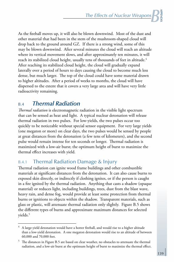
139
The Effects of Nuclear WeaponsBa
ppend
ix
As the fireball moves up, it will also be blown downwind. Most of the dust and other material that had been in the stem of the mushroom-shaped cloud will drop back to the ground around GZ. If there is a strong wind, some of this may be blown downwind. After several minutes the cloud will reach an altitude where its vertical movement slows, and after approximately ten minutes, it will reach its stabilized cloud height, usually tens of thousands of feet in altitude.4 After reaching its stabilized cloud height, the cloud will gradually expand laterally over a period of hours to days causing the cloud to become much less dense, but much larger. The top of the cloud could have some material drawn to higher altitudes. After a period of weeks to months, the cloud will have dispersed to the extent that it covers a very large area and will have very little radioactivity remaining.
B.4 Thermal RadiationThermal radiation is electromagnetic radiation in the visible light spectrum that can be sensed as heat and light. A typical nuclear detonation will release thermal radiation in two pulses. For low-yields, the two pulses occur too quickly to be noticeable without special sensor equipment. For very large yields (one megaton or more) on clear days, the two pulses would be sensed by people at great distances from the detonation (a few tens of kilometers), and the second pulse would remain intense for ten seconds or longer. Thermal radiation is maximized with a low-air burst; the optimum height of burst to maximize the thermal effect increases with yield.
B.4.1 Thermal Radiation Damage & InjuryThermal radiation can ignite wood frame buildings and other combustible materials at significant distances from the detonation. It can also cause burns to exposed skin directly, or indirectly if clothing ignites, or if the person is caught in a fire ignited by the thermal radiation. Anything that casts a shadow (opaque material) or reduces light, including buildings, trees, dust from the blast wave, heavy rain, and dense fog, would provide at least some protection from thermal burns or ignitions to objects within the shadow. Transparent materials, such as glass or plastic, will attenuate thermal radiation only slightly. Figure B.5 shows the different types of burns and approximate maximum distances for selected yields.5
4 A large-yield detonation would have a hotter fireball, and would rise to a higher altitude than a low-yield detonation. A one megaton detonation would rise to an altitude of between 60,000 and 70,000 feet.
5 The distances in Figure B.5 are based on clear weather, no obstacles to attenuate the thermal radiation, and a low-air burst at the optimum height of burst to maximize the thermal effect.

140
Nuclear Matters: A Practical Guide20
08
Flash blindness, or “dazzle,” is a temporary loss of vision caused by the eyes being overwhelmed by the intense thermal light. On a clear night, dazzle can affect people at distances of tens of kilometers and may last for up to 30 minutes. On a clear day, dazzle can affect people at distances well beyond the distances for first degree burns but should last for a shorter period of time. Flash blindness can occur regardless of whether a person is looking toward the detonation because the thermal radiation can be scattered and reflected in the air. At distances where it can produce a first degree burn, it is so intense that it can penetrate through the back of the skull to overwhelm the eyes.
For people looking directly at the fireball at the moment of the detonation, retinal burns can occur at great distances. If the yield is large enough, and the duration of the second thermal pulse is more than one second, some people would look toward the detonation and receive retinal burns. Normally, retinal burns would cause a permanent blindness to a small portion in the center of the normal field of vision. A surface burst would reduce the incidence of both temporary blindness and retinal burns.
B.4.2 Thermal Radiation Employment FactorsFor thermal radiation to cause ignition or burns, the person or object must be in direct line-of-sight from the detonation, without anything opaque in between. For this reason, thermal radiation is maximized with a low-air burst rather than a surface burst because the higher height of detonation provides direct line-of-sight out to much greater distances.
Because thermal radiation can start fires and cause burns at such great distances, if a nuclear weapon were employed against a populated area, on a clear day, with an air burst at approximately the optimum height of burst, it is likely that the thermal effects would account for more casualties than any other effect. With a surface burst, or with rain or fog in the area, the thermal radiation effects would be reduced.
Figure B.5 Thermal Radiation Burns
Degree
3rd
2nd
1st
Affected Area
Tissue under skin
All layers of skin
Outer layers of skin
Description & Symptoms
Charred skin; Extreme pain
Blisters; Severe pain
Red/darker skin; Moderate pain
1 kt
0.7
0.9
1.0
10kt
1.7
2.3
2.8
1MT
11.1
13.7
19.0
Approximate Distances (km)

141
The Effects of Nuclear WeaponsBa
ppend
ix
B.4.3 Thermal Radiation ProtectionThe effects of thermal radiation can be reduced with protective enclosures, thermal protective coatings, and the use of non-flammable clothing, tools, and equipment. Thermal protective coatings include the use of materials that swell when exposed to flame (absorbing the heat rather than allowing it to penetrate through the material), as well as ablative paints, which act like a melting heat shield. Materials like steel, as opposed to temperature-sensitive metals like aluminum, are used to protect against thermal radiation. Similarly, higher-temperature resins are used in forming fiberglass structures. In order to reduce the amount of absorbed energy, light colors and reflective paints are also used. For effective thermal hardening, the use of combustible materials is minimized. Finally, to mitigate the effects of thermal radiation, it is important to protect items prone to melting—such as rubber gaskets, O-rings, and seals—from direct exposure.
B.5 Air BlastFor surface and low-air bursts, the fireball expands, pushing air or ground soil/rock/water immediately away from the point of the detonation.6 Above the ground, a dense wall of air breaks away from the immediate fireball, traveling at great speed. Initially, this blast wave moves at several times the speed of sound, but quickly slows to a point where the leading edge of the blast wave is traveling at the speed of sound (mach one), and it continues at this speed as it moves farther away from GZ. Shortly after breaking away from the fireball, the wall of air reaches its maximum density of overpressure (over the nominal air pressure).7 As the blast wave travels away from this point, the wall of air becomes wider and wider in width, and loses density (overpressure continues to decrease).
At significant distances from GZ, overpressure can have a crushing effect on objects as they are engulfed by the blast wave. In addition to overpressure, the blast wave has an associated wind speed as the blast wave passes any object; this can be quantified as dynamic pressure that can move, rather than crush objects. The blast wave has a positive phase and a negative phase for both overpressure and dynamic pressure. Figure B.6 shows the result of air blast damage to buildings.
6 For a one kiloton, low-air burst nuclear detonation, the immediate fireball would be approximately 30 meters (almost 100 feet) in radius and approximately 60 meters (almost 200 feet) in diameter.
7 At a short distance beyond the radius of the immediate fireball, the blast wave would reach a density of thousands of pounds per square inch.

142
Nuclear Matters: A Practical Guide20
08
B.5.1 Air Blast Damage & InjuryAs the blast wave hits a target object, initially the positive overpressure produces a crushing effect on the object. If the overpressure is great enough, it could cause instant fatality. Less overpressure could collapse the lungs, and at lower levels, could rupture the ear drums. Overpressure can implode a building. Immediately after the positive overpressure has begun to affect the object, the dynamic pressure exerts a force that can move people or objects laterally very rapidly, causing injury or damage. It can also strip a building from its foundation, blowing it to pieces moving away from GZ.
As the positive phase of the blast wave passes an object, it is followed by a vacuum effect, i.e., the negative pressure caused by the lack of air in the space behind the blast wave. This is the beginning of the negative phase of dynamic pressure. The vacuum effect (negative overpressure) could cause a wood-frame building to explode, especially if the positive phase has increased the air pressure inside the building by forcing air in through broken windows. The vacuum effect then causes the winds in the trailing portion of the blast wave to be pulled back into the vacuum. This produces a strong wind moving back toward GZ. While the negative phase of the blast wave is not as strong as the positive phase, it may cause objects to be moved back toward GZ, especially if trees or buildings are weakened severely by the positive phase. Figure B.6 shows the overpressure in psi and the approximate distances associated with various types of structural damage.8
8 The distances in Figure B.6 are based on an optimum height of burst to maximize the blast effect, and no significant terrain that would stop the blast wave (e.g., the side of a mountain). For surface bursts, the distances shown are reduced by approximately 30 to 35 percent for the higher overpressures, and by 40 to 50 percent for one psi.
Figure B.6 Air Blast Damage to Structures
Approx. Overpressure
7 - 9 psi
6 psi
4 psi
2 psi
1 psi
Description
Concrete building collapse
Shatter concrete walls
Wood-frame building collapse
Shatter wood siding panels
Shatter windows
1 kt
0.5
0.6
0.8
1.3
2.2
10kt
1.1
1.3
1.8
2.9
4.7
1MT
5.1
6.1
8.1
13.2
21.6
Approximate Distances (km)

143
The Effects of Nuclear WeaponsBa
ppend
ix
B.5.2 Air Blast Employment FactorsIf the detonation occurs at ground level, the expanding fireball will push into the air in all directions, creating an ever-expanding hemispherical blast wave, called the incident wave. As the blast wave travels away, its density continues to decrease, until after some significant distance, it no longer has destructive potential and becomes a mere gust of wind. However, if the detonation is a low-air burst, a portion of the blast wave travels down toward the ground and is reflected off the ground. This reflected wave travels up and out in all directions, reinforcing the incident wave traveling along the ground. Figure B.7 shows the sequence of the incident wave moving away from the fireball, the reflected wave “bouncing” off the Earth’s surface, and the formation of the reinforced blast wave. Because of this factor, air blast is maximized with a low-air burst rather than a surface burst.
If the terrain has a surface that will absorb thermal radiation more than grass or normal soil (e.g., sand, asphalt, etc.), the thermal radiation will heat the surface more than normal, giving off heat prior to the arrival of the blast wave. This is a “non-ideal” condition that will cause the blast wave to become distorted when it reaches the heated surface, causing an abnormal reduction in the density of the blast wave and abnormally reduced psi. Extremely cold weather (-50o F or colder) could cause increased air blast damage distances for some equipment and structures. For surface bursts against a populated area, or if there is rain or fog in the area, the blast effect would probably account for more casualties than any other effect.
B.5.3 Air Blast ProtectionStructures and equipment can be reinforced to make them less vulnerable to air blast. However, any structure or piece of equipment will be destroyed if it is very close to the detonation. High priority facilities that must survive a close nuclear strike are usually constructed underground, making them much harder to defeat.
People who sense a blinding white flash and intense heat coming from one direction (the thermal radiation) should fall to the ground immediately and
Figure B.7 Low-Air Burst Reinforced Blast Wave

144
Nuclear Matters: A Practical Guide20
08
cover their head with their arms. This will provide the highest probability that the air blast will pass overhead without moving the person laterally or having debris in the blast wave cause impact or puncture injuries. Exposed people that are very close to the detonation have no chance of survival. However, at distances where a wood frame building can survive, an exposed person would significantly increase their chance of survival if they are flat on the ground when the blast wave arrives, and remain on the ground until after the negative phase blast wave has moved back toward GZ.
B.6 Ground ShockFor surface or near-surface detonations, the fireball’s expansion and interaction with the ground causes a significant shock wave to move into the ground in all directions. This causes an underground fracture or “rupture” zone. The intensity and significance of the shock wave and the fracture zone decrease with distance from the detonation. A surface burst will produce significantly more ground shock than a near-surface burst where the fireball barely touches the ground.
B.6.1 Ground Shock Damage & InjuryUnderground structures, especially ones that are very deep underground, are not vulnerable to the direct primary effects of a low-air burst. However, the shock produced by a surface burst may damage or destroy an underground target, depending on the yield of the detonation, the soil or rock type, the depth of the target, and its type of structure. It is possible for a surface detonation to fail to crush a deep underground structure but to have an effective shock wave that crushes or buries entrance/exit routes and destroys connecting communications lines. This could cause the target to be “cut-off” and, at least temporarily, incapable of performing its intended function.
B.6.2 Ground Shock Employment FactorsNormally, a surface burst or shallow sub-surface burst is used to attack deeply buried targets. As a simple rule of thumb, a one kt surface detonation can destroy an underground facility as deep as a few tens of meters. A one MT surface detonation can destroy the same target as deep as a few hundreds of meters.
Deeply buried underground targets can be attacked by employing an earth-penetrating warhead to produce a shallow sub-surface burst. Only a few meters of penetration into the earth is required to achieve a “coupling” effect, where most of the energy that would have gone up into the air with a surface burst is trapped by the material near the surface and reflected downward to reinforce

145
The Effects of Nuclear WeaponsBa
ppend
ix
the original shock wave. This reinforced shock wave is significantly stronger and can destroy deep underground targets to distances that are usually between two and five times deeper.9 Ground shock is the governing effect for damage estimation against any underground target.
B.6.3 Ground Shock ProtectionUnderground facilities and structures can be buried deeper to reduce their vulnerability to damage or collapse from a surface or shallow sub-surface detonation. Facilities and equipment can be built with structural reinforcement or other unique designs to make them less vulnerable to ground shock. As a part of functional survivability, the requirement for entrance/exit routes must be considered, as well as any communications lines that must connect to equipment at ground level.
B.7 Surface CraterFor near-surface, surface, and shallow sub-surface bursts, the fireball’s interaction with the ground causes it to engulf much of the soil and rock within its radius, and remove that material as it moves upward. This evacuation of material results in the formation of a crater. A near-surface burst would produce a small, shallow crater. The crater from a surface burst with the same yield would be larger and deeper; crater size is maximized with a shallow sub-surface burst at the optimum depth.10 The size of the crater is a function of the yield of the detonation, the depth of burial, and the type of soil or rock.
For deeply buried detonations, such as those created with underground nuclear testing, the expanding fireball creates a spherical volume of hot radioactive gases. As the radioactive gas cools and contracts, the spherical volume of space becomes an empty cavity with a vacuum effect. The weight of the heavy earth above this cavity and the vacuum effect within the cavity cause a downward pressure for the earth to fall in on the cavity. This can occur, unpredictably, at any time from minutes to months after the detonation. When it occurs, the cylindrical mass of earth collapsing down into the cavity will form a crater on the surface, called a subsidence crater. Figure B.8 shows the Sedan crater formed at the Nevada Test Site by a 104 kt detonation at an optimum depth of 193.5 meters (635 feet). The Sedan subsidence crater is approximately 390 meters (1,280 feet) in diameter and 98 meters (320 feet) deep.
9 The amount of increased depth of damage is primarily a function of the yield and the soil or rock type.
10 For a one kt detonation, the maximum crater size would have a depth of burial between 32 and 52 meters, depending on the type of soil or rock.

146
Nuclear Matters: A Practical Guide20
08
B.7.1 Surface Crater Damage & InjuryIf a crater has been produced by a detonation near the surface within the last several days, it will probably be radioactive. People who are required to enter or cross such a crater could be exposed to significant levels of ionizing
radiation, possibly enough to cause casualties or fatalities.
If a deep underground detonation has not yet formed the subsidence crater, it would be very dangerous to enter the area on the surface directly above the detonation.
B.7.2 Surface Crater Employment FactorsNormally, the wartime employment of nuclear weapons does not use crater formation to attack targets. At the height of the Cold War, NATO forces had contingency plans to use craters from nuclear detonations to channel, contain, or block enemy ground forces. The size of the crater, and its radioactivity for the first several days, would produce an obstacle that would be extremely difficult, if not impossible, for a military unit to move over it.
B.7.3 Surface Crater ProtectionA crater by itself does not present a hazard to people or equipment, unless the person tries to drive or climb into the crater. For deep underground detonations, the rule is to keep away from the area where the subsidence crater will be formed until after the collapse occurs.
B.8 Underwater ShockA nuclear detonation underwater generates a shock wave similar to the way a blast wave is formed in the air. The expanding fireball pushes water away from the point of detonation creating a rapidly moving dense wall of water. In the deep ocean, this underwater shock wave moves out in all directions, gradually losing its intensity. In shallow water, it can be distorted by surface and bottom reflections. Shallow bottom interactions may reinforce the shock effect, but surface interaction will generally mitigate the shock effect.
Figure B.8 Sedan Subsidence Crater

147
The Effects of Nuclear WeaponsBa
ppend
ix
If the yield is large enough and the depth of detonation is shallow enough, the shock wave will rupture the water’s surface. This can produce a large surface wave that will move away in all directions. It may also produce a “spray dome” of radioactive water above the surface.
B.8.1 Underwater Shock Damage & InjuryIf a submarine is close enough to the detonation, the underwater shock wave will be strong enough to move the vessel rapidly. This near instantaneous movement could force the ship against the surrounding water with a force beyond its design capability, causing a structural rupture of the vessel. The damage to the submarine is a function of weapon yield, depth of detonation, depth of the water under the detonation, bottom conditions, and the distance and orientation of the submarine. People inside the submarine are at risk if the boat’s structure fails.
Surface ships may be vulnerable to the underwater shock wave striking its hull. If the detonation produces a significant surface wave, it could damage surface ships at greater distances. If ships move into the radioactive spray dome, it could present a radioactive hazard to people on the ship.
B.8.2 Underwater Shock Employment FactorsNormally, nuclear weapons are not used to target enemy naval forces.
B.8.3 Underwater Shock ProtectionBoth surface ships and submarines can be designed to be less vulnerable to the effects of underwater nuclear detonations. However, any ship or submarine will be damaged or destroyed if it is close enough to a nuclear detonation.
B.9 Initial Nuclear RadiationNuclear radiation is ionizing radiation emitted by nuclear activity, consisting of neutrons, alpha and beta particles, as well as electromagnetic energy in the form of gamma rays.11 Gamma rays are high-energy photons of electromagnetic radiation with frequencies higher than visible light or ultraviolet rays.12 Gamma rays and neutrons are produced from fission events. Alpha and beta particles, as
11 Ionizing radiation is defined as electromagnetic radiation (gamma rays or X-rays) or particulate radiation (alpha particles, beta particles, neutrons, etc.) capable of producing ions (electrically charged particles) directly or indirectly in its passage through matter.
12 A photon is a unit of electromagnetic radiation consisting of pure energy and zero mass; the spectrum of photons include AM radio waves, FM radio waves, radar- and micro-waves, infrared waves, visible light, ultraviolet waves, X-rays, and gamma/cosmic rays.

148
Nuclear Matters: A Practical Guide20
08
well as gamma rays, are produced by the radioactive decay of fission fragments. Alpha and beta particles are absorbed by atoms and molecules in the air at short distances, and are insignificant compared with other effects. Gamma rays and neutrons travel great distances through the air in a general direction away from GZ.13
Because neutrons are produced almost exclusively by fission events, they are produced in a fraction of a second, and there are no significant number of neutrons produced after that. Conversely, gamma rays are produced by the decay of radioactive materials and will be produced for years after the detonation. Most of these radioactive materials are initially in the fireball. For surface and low-air bursts, the fireball will rise quickly, and within approximately one minute, will be at an altitude high enough that none of the gamma radiation produced inside the fireball would have any impact to people or equipment on the ground. For this reason, initial nuclear radiation is defined as the nuclear radiation produced within one minute after the detonation. Initial nuclear radiation is also called prompt nuclear radiation.
B.9.1 Initial Nuclear Radiation Damage & InjuryThe huge number of gamma rays and neutrons produced by a surface, near-surface, or low-air burst may cause casualties or fatalities to people at significant distances. For a description of the biological damage mechanisms, see the section on the Biological Effects of Ionizing Radiation below. The unit of measurement for radiation exposure is the centi-Gray (cGy).14 Figure B.9 shows selected levels of exposure, the associated prompt effects on humans, and the distances by yield.15 The 450 cGy exposure dose level is considered to be the lethal dose for 50 percent of the population (LD50). People who survive at this dose level would have a significantly increased probability of contracting mid-term and long-term cancers, including lethal cancers.
Low levels of exposure can increase a person’s risk for contracting long-term cancers. For example, for healthy male adults age 20 to 40, an exposure of 100
13 Both gamma rays and neutrons will be scattered and reflected by atoms in the air, causing each gamma photon and each neutron to travel a “zig-zag” path moving generally away from the detonation. Some neutrons and photons may be reflected so many times that, at a significant distance from the GZ, they will be traveling back toward the GZ.
14 One cGy is an absorbed dose of radiation equivalent to 100 ergs of ionizing energy per gram of absorbing material or tissue. The term centi-Gray replaced the older term radiation absorbed dose (RAD).
15 For the purposes of this appendix, all radiation doses are assumed to be acute (total radiation received within approximately 24 hours) and whole-body exposure. Exposures over a longer period of time (chronic), or exposures to an extremity (rather than to the whole body) could have less impact to a person’s health.

149
The Effects of Nuclear WeaponsBa
ppend
ix
cGy will increase the risk of contracting any long-term cancer by approximately 10 to 15 percent, and for lethal cancer by approximately 6 to 8 percent.16
Initial nuclear radiation can also damage the electrical components in certain equipment. See the section on Transient Radiation Effects on Electronics (TREE) below.
B.9.2 Initial Nuclear Radiation Employment FactorsThe ground absorbs both gamma rays and neutrons much more than air can absorb them. A surface burst will have almost half the initial nuclear radiation absorbed quickly by the earth. A low-air burst will also have half the nuclear radiation traveling in a downward direction, but much of that will be scattered and reflected by atoms in the air and can add to the amount of radiation traveling away from GZ. For this reason, initial nuclear radiation is maximized with a low-air burst rather than a surface burst. Generally, the effects of initial nuclear radiation for lower yield weapons are more significant, compared with other effects, than they are with higher-yield weapons.
Initial nuclear radiation effects can be predicted with reasonable accuracy. Some non-strategic targets, or theater, may have personnel as one of the primary target elements. In this case, initial nuclear radiation is considered with air blast to determine the governing effect. Initial nuclear radiation is always considered for safety (if safety of populated areas or friendly troop personnel is a factor), and safety distances are calculated based on a “worst-case” assumption, i.e., that there will be maximum initial radiation effect, and that objects in the target area will not shield or attenuate the radiation.
16 Calculated from data in Health Risks from Exposure to Low Levels of Ionizing Radiation: BEIR VII - Phase 2, National Academy of Sciences, Committee to Assess Health Risks from Exposure to Low Levels of Ionizing Radiation, 2006.
Figure B.9 Prompt Effects of Initial Nuclear Radiation
Level of Exposure
3,000 cGy
650 cGy
450 cGy
150 cGy
Description
Prompt casualty; death within days
Delayed casualty; ~95% death in wks
Performance impaired; ~50% death
Threshold symptoms
1 kt
0.5
0.7
0.8
1.0
10kt
0.9
1.2
1.3
1.5
1MT
2.1
2.4
2.6
2.8
Approximate Distances (km)

150
Nuclear Matters: A Practical Guide20
08
B.9.3 Initial Nuclear Radiation ProtectionThere is very little a person can do to protect themselves against initial nuclear radiation after the detonation has occurred because the radiation is emitted and absorbed in less than one minute. The DoD has developed an oral chemical prophylactic to reduce the effects of ionizing radiation exposure, but the drug does not reduce the hazard to zero. Just as with most of the other effects, if a person is very close to the detonation, it will be fatal.
Generally, structures are not vulnerable to initial nuclear radiation. Equipment can be hardened to make electronic components less vulnerable to initial nuclear radiation.
B.10 Residual Nuclear RadiationResidual nuclear radiation consists of alpha and beta particles and gamma rays emitted from the nuclei during the decay of radioactive material. For a typical detonation, there are two primary categories of residual nuclear radiation: induced radiation and fallout. A deep underground detonation would have the same categories, but the radiation would remain deep underground, unless there were a venting of radioactive gases from the fireball, or if other residual radiation escaped by another means, e.g., through an underground water flow. An exo-atmospheric detonation would create a cloud that could remain significantly radioactive in orbit for many months.
For typical surface or low-air burst detonations, there will be two types of induced radiation. The first type is neutron-induced soil on the ground, called an “induced pattern.” Neutrons emitted from the detonation are captured by light metals in the soil or rock near the ground surface.17 These atoms become radioactive isotopes capable of emitting, among other things, gamma radiation. The induced radiation is generally created in a circular pattern around the GZ. It is most intense at GZ and immediately after the detonation. The intensity decreases with distance from GZ, and it will also decrease over time. For normal soil, it would take approximately five to seven days to decay to a safe level.
Another type of induced radiation is the production of carbon-14 by the absorption of fission neutrons in nitrogen in the air. The carbon-14 atoms can remain suspended in the air, are beta particle emitters, and have a long half-life (5,715 years).
17 Neutrons induced into typical soil are captured primarily by sodium, manganese, silicon, and aluminum atoms.

151
The Effects of Nuclear WeaponsBa
ppend
ix
Fallout is the release of small radioactive particles that drop from the fireball to the ground. In most technical jargon, fallout is defined as the fission fragments from the nuclear detonation. However, the fireball will contain other types of radioactive particles that will also fall to the ground contributing to the total radioactive hazard. These include the radioactive fissile material that did not undergo fission (no weapon is so efficient to fission 100 percent of the fissile material), and material of the warhead components that have been induced with neutrons and have become radioactive.
Residual gamma radiation is colorless, odorless, and tasteless. Unless there is an extremely high level of radiation, it cannot be detected with the five senses.
B.10.1 Residual Nuclear Radiation Damage & InjuryUsually, a deep underground detonation presents no residual radiation hazard to people or objects on the surface. If there is an accidental venting or some other unintended escape of radioactivity, however, that could become a radioactive hazard to people in the affected area. The residual nuclear cloud from an exo-atmospheric detonation could damage electronic components in some satellites over a period of time (usually months or years), depending on how close a satellite gets to the radioactive cloud, the frequency of the satellite passing near the cloud, and its exposure time.
If a nuclear device is detonated in a populated area, it is possible that the induced radiation could extend to distances beyond building collapse, especially with a low-yield device. This could cause first responders who are not trained to understand induced radiation to move toward GZ intending to help injured people, and to move into an area that is still radioactively hot. Without radiation detectors, the first responders would not be aware of the radioactive hazard.
Between the early-1950s and 1962, when the four nuclear nations were conducting above ground nuclear testing, there was a two to three percent increase in total carbon-14 worldwide. Gradually, the amount of carbon-14 is returning to pre-testing levels. While there are no known casualties caused by the carbon-14 increase, it is logical that any increase over the natural background level could be an additional risk. If nuclear-capable nations were to return to nuclear testing in the atmosphere, carbon-14 could become a hazard for the future.
Normally, fallout should not be a hazardous problem for a detonation that is a true airburst. However, if rain or snow is falling in the target area, radioactive particles could be “washed-out” of the fireball, causing a hazardous area of early fallout. If a detonation is a surface or near-surface burst, early fallout would be a significant radiation hazard around GZ and downwind.

152
Nuclear Matters: A Practical Guide20
08
B.10.2 Residual Nuclear Radiation Employment FactorsIf the detonation is a true air burst, where the fireball does not interact with the ground or any significant structure, the size and heat of the fireball will cause it to retain almost all of the weapon debris (usually one or at most a few tons of material) as it moves upward in altitude and downwind. In this case, very few particles fall to the ground at any moment, and there is no significant radioactive hot-spot on the ground caused by the fallout. The fireball will rise to become a long-term radioactive cloud. The cloud will travel with the upper atmospheric winds, and it will circle the hemisphere several times over a period of months before it dissipates completely. Most of the radioactive particles will decay to stable isotopes before falling to the ground. The particles that reach the ground will be distributed around the hemisphere at the latitudes of the cloud travel route. Even though there would be no location receiving a hazardous amount of fallout radiation, certain locations on the other side of the hemisphere could receive more fallout radiation (measurable with radiation detectors) than the area near the detonation. This is called worldwide fallout.
If the fireball interacts with the ground or any significant structure (e.g., a large bridge or a large building), the fireball would have different properties. In addition to the three types of radioactive material mentioned in the previous paragraph, the fireball would also include radioactive material from the ground (or from the structure) that has been induced with neutrons. The amount of material in the fireball would be much greater than the amount with an air burst. For a true surface burst, a one kt detonation would extract thousands of tons of earth up into the fireball (although only a small portion would be radioactive). This material would disintegrate and mix with the radioactive particles. As large and hot as the fireball is (for a one kt, almost 200 feet in diameter and tens of millions of degrees), it has no potential to hold up and carry thousands of tons of material. Thus, as the fireball rises, it would begin to release a significant amount of radioactive dust, which would fall to the ground and produce a radioactive fallout pattern around GZ and moving downwind. The intensity of radioactivity in this fallout area would be hazardous for weeks. This is called early fallout. It is caused primarily by a surface burst detonation regardless of the weapon design.
B.10.3 Residual Nuclear Radiation ProtectionThere are four actions that are the primary protection against residual radiation. First, personnel with a response mission should enter the area with at least one radiation detector, and all personnel should employ personal protective

153
The Effects of Nuclear WeaponsBa
ppend
ix
equipment (PPE).18 While the PPE will not stop the penetration of gamma rays, it will prevent the responder personnel from breathing in any airborne radioactive particles. Second, personnel should remain exposed to radioactivity for the minimum time possible to accomplish a given task. Third, personnel should remain at a safe distance from radioactive areas. Finally, personnel should use shielding when possible to further reduce the amount of radiation received. It is essential for first-responder personnel to follow the principles of PPE, time, distance, and shielding.
Equipment may be designed to be “rad-hard” if it is a requirement. See Appendix C, Nuclear Weapons Effects Survivability and Testing, for a discussion of the U.S. survivability program.
B.11 Biological Effects of Ionizing RadiationIonizing radiation is any particle or photon that can produce an ionizing event, i.e., stripping one or more electrons away from their parent atom. It includes alpha particles, beta particles, gamma rays, cosmic rays (all produced by nuclear actions), and X-rays (not produced by nuclear actions).
B.11.1 Ionizing Radiation Damage & InjuryIonizing events cause biological damage to humans and other mammals. Figure B.10 shows the types of life-essential molecular ionization and the resulting biological problem. Generally, the greater the exposure dose, the greater the biological problems caused by the ionizing radiation.
At medium and high levels of exposure, there are near-term consequences, including impaired performance, becoming an outright casualty, and death. See Figure B.9 for a description of these problems at selected dose levels. People who survive at this dose level would have a significantly increased probability of contracting mid-term and long-term cancers, including lethal cancers.
18 PPE for first-responders includes a sealed suit and self-contained breathing equipment with a supply of oxygen.
Figure B.10 Biological Damage from Ionization
Resulting Problem
Abnormal cell reproduction
Creates hydrogen peroxide (H2O2)
Cell death
Loss of muscle control
Loss of thought process & muscle control
Ionized Objects
Ionized DNA molecules
Ionized water molecules
Ionized cell membrane
Ionized central nervous system molecules
Ionized brain molecules

154
Nuclear Matters: A Practical Guide20
08
At low levels of exposure, there are no near-term medical problems. However, at 75 cGy, approximately five percent of healthy adults will experience mild threshold symptoms, i.e., transient mild headaches and mild nausea. At 100 cGy, approximately 10-15 percent would experience these threshold symptoms, with a smaller percentage experiencing some vomiting. It is also possible that some people could experience near-term psychosomatic symptoms, especially if they respond to inaccurate reports by the news media or others. Low exposure levels also result in some increased probability of contracting mid-term and long-term cancers, including lethal cancers. Figure B.11 shows the increased probability for healthy adults, by gender.
B.11.2 Ionizing Radiation ProtectionShielding can be achieved with most materials, however, some require much more material; to reduce the penetrating radiation by half. Figure B.12 shows the widths required for selected types of material to stop half the gamma radiation (called “half-thickness”) and to stop 90 percent of the radiation (called “tenth-value thickness”).
B.12 ElectroMagnetic Pulse (EMP)Electromagnetic Pulse (EMP) is a very short duration pulse of low-frequency (long-wavelength) electromagnetic radiation (EMR). It is produced when a nuclear detonation occurs in a non-symmetrical environment, especially at or near the Earth’s surface or at high altitudes.19 The interaction of gamma rays, X-rays, and neutrons with the atoms and molecules in the air generates an instantaneous flow of electrons, generally in a direction away from the detonation. These electrons immediately change direction (primarily because of
19 EMP may also be produced by conventional methods.
Figure B.11 Increased Risk - Low Level Exposure
Healthy Males, age 20-40Approximate Increased Risk (Probability) of Cancer (percent)
Healthy Females, age 20-40Level of Ionizing Radiation Exposure
100 cGy
50 cGy
25 cGy
10 cGy
1 cGy
Lethal
6 - 8
2 - 3
1 - 2
< 1
< 1
All Cancers
10 -15
4 - 6
2 - 3
1
< 1
All Cancers
13 - 25
5 - 10
2 - 5
1 - 2
< 1
Lethal
7 - 12
3 - 5
1 - 2
1
< 1

155
The Effects of Nuclear WeaponsBa
ppend
ix
the Earth’s magnetic field) and velocity, emitting low frequency EMR photons. This entire process occurs almost instantaneously (measured in millionths of a second) and produces a huge number of photons.
B.12.1 EMP Damage & InjuryAny unprotected equipment with electronic components could be vulnerable to EMP. A large number of low-frequency photons can be absorbed by any antenna of any component that acts as an antenna. This energy moves within the equipment to any unprotected electrical wires or electronic components and generates a flow of electrons. The electron flow becomes voltage within the electronic component or system. Modern electronic equipment using low voltage components can be overloaded with a voltage beyond its designed capacity. At low levels of EMP, this can cause a disruption of processing, or a loss of data. At increased EMP levels, certain electronic components will be destroyed. EMP can damage unprotected electronic equipment, including computers, vehicles, aircraft, communications equipment, and radars. EMP will not produce structural damage to buildings, bridges, etc.
EMP is not a direct hazard to humans. However the indirect effects of electronics failing instantaneously in vehicles, aircraft, life-sustaining equipment in hospitals, etc., could cause injuries or fatalities.
B.12.2 EMP Employment FactorsA high-altitude detonation, or an exo-atmospheric detonation within a certain altitude range band, will generate an EMP that could cover a very large region of the Earth’s surface, as large as 1.000 kilometers across. A surface or low-air burst would produce local EMP with severe intensity, traveling through the air out to distances that could go beyond the distances of building collapse (hundreds of meters). Generally, the lower the yield, the more significant is the EMP compared with air blast. Again, within this area, unprotected electronic
Figure B.12 Radiation Shielding
3.3
11.0
16.024.0
38.0
Tenth-ValueThickness(inches)
1.0
3.3
4.87.2
11.4
Half-Thickness(inches)
Steel / Iron
Concrete
EarthWater
Wood
Material

156
Nuclear Matters: A Practical Guide20
08
components would be vulnerable. Electrical lines and telephone wires would carry the pulse to much greater distances, possibly ten kilometers, and could destroy any electronic device connected to the power lines.
Because electronic equipment can be hardened against the effects of EMP, it is not considered in traditional approaches for damage estimation.
B.12.3 EMP ProtectionElectronic equipment can be EMP-hardened. The primary objective of EMP hardening is to reduce the electrical pulse entering a system or piece of equipment to a level that will not cause component burnout or operational upset. It is always cheaper and more effective to design the EMP protection into the system during design development. Potential hardening techniques include using certain materials as radio frequency shielding filters, using internal enclosed protective “cages” around essential electronic components, using enhanced electrical grounding, shielded cables, keeping the equipment in closed protective cases, or keeping the equipment in an EMP-protected room or facility. Normally, the hardening that permits equipment to operate in intense radar fields (e.g., helicopters that operate in front of a ship’s radars) also provides a significant degree of EMP protection.
Because the EMP is of such short duration, home circuit-breakers, typical surge-protectors, and power strips are useless against EMP. These devices are designed to protect equipment from electrical surges caused by lightning, but they cannot defend against EMP because it is thousands of times faster than the pulse of lightning.
B.13 Transient Radiation Effects on Electronics (TREE)
Transient Radiation Effects on Electronics (TREE) is the damage to electronic components by initial nuclear radiation gamma rays and neutrons.
B.13.1 TREE Damage & InjuryThe gamma rays and neutrons produced by a nuclear detonation are transient initial nuclear radiation which can affect electronic components and associated circuitry by penetrating deep into materials and electronic devices. Gamma rays can induce stray currents of electrons that generate harmful electromagnetic fields similar to EMP. Neutrons can collide with atoms in key electronic materials causing damage to the crystal (chemical) structure and changing electrical properties. While all electronics are susceptible to the effects of TREE, smaller, solid-state electronics such as transistors and integrated circuits are most vulnerable to these effects.

157
The Effects of Nuclear WeaponsBa
ppend
ix
Although initial nuclear radiation may pass through material and equipment in a matter of seconds, the damage is usually permanent.
B.13.2 TREE Employment FactorsWith a high-altitude or exo-atmospheric burst, prompt gamma rays and neutrons can reach satellites or other space systems. If these systems receive large doses of this initial nuclear radiation, their electrical components can be damaged or destroyed. If a nuclear detonation is a low-yield surface or low-air burst, the prompt gamma rays and neutrons could be intense enough to damage or destroy electronic components at distances beyond air blast damage to that equipment. Because electronic equipment can be hardened against the effects of TREE, it is not considered in traditional approaches to damage estimation.
B.13.3 TREE Protection Equipment that is designed to be protected against TREE is called “rad-hardened.” The objective of TREE hardening is to reduce the effect of the gamma and neutron radiation from damaging electronic components. Generally, special shielding designs can be effective, but TREE protection may include using shielded containers with a mix of heavy shielding for gamma rays and certain light materials to absorb neutrons. Just as with EMP hardening, it is always cheaper and more effective to design the EMP protection into the system during design development.
B.14 Black-OutBlack-out is the interference with radio and radar waves due to an ionized region of the atmosphere. Nuclear detonations, other than those underground or far away in outer space, will generate the flow of a huge number of gamma rays and X-rays, moving in a general direction away from the detonation. These photons will produce a large number of ionizing events in the atoms and molecules in the air, creating a very large region of ions. A large number of electrons are stripped away from their atoms, and move in a direction away from the detonation. This leaves a large number of positively charged atoms closer to the detonation, creating an ionized region with positively charged atoms close to the detonation and negatively charged particles farther from the detonation.
B.14.1 Black-Out Damage & InjuryBlackout cannot cause damage or injuries directly. The interference with communications or radar operations could cause accidents indirectly, e.g., the loss of air traffic control, due to either loss of radar capability or the loss of communications, could affect several aircraft simultaneously.

158
Nuclear Matters: A Practical Guide20
08
B.14.2 Black-Out Employment FactorsA high-altitude or exo-atmospheric detonation would produce a very large ionized region of the upper atmosphere that could be as large as thousands of kilometers in diameter. This ionized region could interfere with communications signals to and from satellites and with AM radio transmissions that rely on atmospheric reflection if those signals have to travel through or near the ionized region. Under normal circumstances, this ionized region interference would continue for a period of time up to several hours after the detonation. The ionized region can affect different frequencies out to different distances and for different periods of time.
A surface or low-air burst would produce a smaller ionized region of the lower atmosphere that could be as large as tens of kilometers in diameter. This ionized region could interfere with VHF and UHF communications signals and with radar waves that rely on pin-point line-of-sight transmissions if those signals have to travel through or near the ionized region. Under normal circumstances, this low altitude ionized region interference would continue for a period of time up to a few tens of minutes after the detonation. Again, the ionized region can affect different frequencies out to different distances and for different periods of time.
B.14.3 Black-Out ProtectionThere is no direct protection against the black-out effect.

159
C.1 Overview It is common to confuse nuclear weapons effects survivability with nuclear weapons system survivability. Nuclear weapon effects survivability applies to the ability of any and all personnel and equipment to withstand the blast, thermal radiation, nuclear radiation, and electromagnetic pulse (EMP) effects of a nuclear detonation. Thus, nuclear weapons effects survivability includes, but is not limited to, nuclear weapons systems.
Nuclear weapons system survivability is concerned with the ability of our nuclear deterrent forces to survive against the entire threat spectrum that includes, but is not limited to, nuclear weapons effects. The vast range of potential threats include: conventional and electronic weaponry; nuclear, biological, and chemical contamination; advanced technology weapons such as high-power microwaves and radio frequency weapons; terrorism or sabotage; and the initial effects of a nuclear detonation.
In simple terms, nuclear weapons effects survivability refers to any and all personnel, equipment, and systems (including, but not limited to, nuclear systems) being able to survive nuclear weapons effects. Nuclear weapons system survivability refers to nuclear weapons systems being survivable against any threat (including, but not limited to, the nuclear threat). See Figure C.1 for a summary of the differences between nuclear weapons effects and nuclear weapons system survivability. An overlap occurs when the threat to the survivability of a nuclear weapons system is a nuclear detonation and its effects. Figure C.2 illustrates the intersection between nuclear effects survivability and systems survivability.
Nuclear weapons effects survivability refers to the capability of a system to withstand exposure to a nuclear weapons effects environment without suffering the loss of its ability to accomplish its designated mission. Nuclear weapons effects survivability may be accomplished by hardening, timely re-supply, redundancy, mitigation techniques (to include operational techniques), or a combination thereof. Systems can be nuclear hardened to survive prompt nuclear weapons effects including blast, thermal radiation, nuclear radiation, EMP, and in some cases, Transient Radiation Effects on Electronics (TREE). For a description of these effects see Appendix B, The Effects of Nuclear Weapons.
Appendix CNuclear Weapons EffectsSurvivability and Testing

160
Nuclear Matters: A Practical Guide20
08
Nuclear hardness describes the ability of a system to withstand the effects of a nuclear detonation and avoid internal malfunction or performance degradation. Hardness measures the ability of a system’s hardware to withstand physical effects such as overpressure, peak velocities, energy absorbed, and electrical stress. This reduction in hardware vulnerability can be achieved through a variety of well-established design specifications or through the selection of well-built and well-engineered components. This appendix does not address residual nuclear weapons effects such as fallout, nor does it discuss nuclear contamination survivability.1
Mechanical and structural effects hardening consists of using robust designs, protective enclosures, protective coatings, and the proper selection of materials.
1 For information on fallout and nuclear contamination, see Samuel Glasstone and Philip Dolan, The Effects of Nuclear Weapons 3rd Edition, United States Department of Defense and the Energy Research and Development Administration, 1977.
NuclearWeaponsSystems
SurvivabilityAgainstNuclear
WeaponsEffects
NuclearWeaponsEffects
Survivability
NuclearWeaponsSystems
Survivability
Figure C.2 Intersection of Nuclear Effects Survivability and Systems Survivability
Nuclear Weapons Effects Survivabilty
Survivability of Everything - Nuclear Weapons - Nuclear Force Personnel - Nuclear Force Equipment - Conventional Weapons - Conventional Force Personnel - Conventional Equipment
Against the Effects of Nuclear Weapons
Nuclear Weapons System Survivabilty
Survivability of Nuclear Forces - Nuclear Weapons - Nuclear Force Personnel - Nuclear Force Equipment
Against the Effects of Any Threat - Nuclear Weapons - Chemical, Biological Weapons - Conventional Weapons - Advanced Technology Weapons - Special Ops Attack - Terrorist Attack
Figure C.1 Nuclear Weapons Effects vs System Survivability

161
Nuclear Weapons Effects Survivability and TestingCa
ppend
ix
Electronics and electrical effects hardening involves using the proper components, special protection devices, circumvention circuits, and selective shielding. Nuclear weapons effects on personnel are minimized by avoidance, radiation shielding protection, and automatic recovery measures. The automatic recovery measures compensate for the temporary loss of the “man-in-the-loop” and mitigate the loss of military function and the degradation of mission accomplishment.
Trade-off analyses are conducted during the acquisition process of a system to determine the method or combination of methods that provide the most cost-effective approach to nuclear weapons effects survivability. The impact of the nuclear weapons effects survivability approach on system cost, performance, reliability, maintainability, productivity, logistics support, and other requirements are examined to ensure maximum operational effectiveness consistent with program constraints. The different approaches to hardening are not equally effective against all initial nuclear weapons effects.
C.2 Nuclear Weapons Effects SurvivabilityEach of the primary and secondary environments produced by a nuclear detonation causes a unique set of mechanical and electrical effects. Some effects are permanent and others are transient. Both types can cause system malfunction, system failure, or loss of combat capability.
C.2.1 Nuclear Weapons Effects on Military SystemsThe nuclear environments and effects that may threaten the survivability of a military system vary with the altitude of the explosion. The dominant nuclear environment refers to the effects that set the survival range between the target and the explosion.2 Low-air, near-surface, and surface bursts will damage most ground targets within the damage radii. Also, high-altitude bursts produce high-altitude electromagnetic pulse (HEMP) effects over a very large area that may damage equipment with vulnerable electronics on the ground. Figure C.3 highlights the nuclear environments that dominate the survival for typical systems based on various heights of burst from space to below the Earth’s surface.
Nuclear weapons-generated X-rays are the chief threat to the survival of strategic missiles in-flight above the atmosphere and to satellites. Neutron and gamma ray effects also create serious problems for these systems but do not normally set the survivability range requirements. Neutron and gamma ray
2 The survival range measures the distance from Ground Zero (GZ) necessary to survive nuclear weapons effects.

162
Nuclear Matters: A Practical Guide20
08
effects dominate at lower altitudes where the air absorbs most of the X-rays. Air blast and thermal radiation effects usually dominate the survival of systems at or near the surface; however, neutrons, gamma rays, and Source Region EMP (SREMP) may also create problems for structurally hard systems that are near the explosion. SREMP is produced by a nuclear burst within several hundred meters of the Earth’s surface and is localized out to a distance of three to five kilometers from the burst. The final result of the EMP generated by the detonation is a tremendous surge of low frequency photons that can enter a system through designed and unintended antennas, generating a flow of electrical current that overloads and destroys electrical components, and renders the equipment non-operational.
Underwater shock and ground shock are usually the dominant nuclear weapons effects for submerged submarines and buried shelters, respectively. HEMP is the dominant threat for surface-based systems located outside the target zone such as Command, Control, Communications, and Intelligence (C3I) facilities or sophisticated electronics.
Nuclear weapons effects survivability requirements vary with the type of system, its mission, its operating environment, and the threat. For example, the X-ray, gamma ray, and neutron survivability levels used for satellites are very low compared with the survivability levels used for missiles and Re-entry Vehicles (RVs), or Re-entry Bodies (RBs). Satellite levels are usually set so that a single nuclear weapon, detonated in the region containing several satellites, will not damage or destroy more than one satellite. The levels used for RVs, on the
Dominating Environment
Underwater andUnderground Shock
SREMP
Nuclear RadiationHEMP
Blast and Thermal
Nuclear RadiationHEMP
Nuclear RadiationBlast and Thermal
SREMP
X-rays and Nuclear Radiation
Sub-Surface
Surface
Low-Altitude
Mid-Altitude
High-Altitude
Exo-Atmosphere
Figure C.3 Dominant Nuclear Environments as a Function of Altitude

163
Nuclear Weapons Effects Survivability and TestingCa
ppend
ix
other hand, are very high because the RV/RB is the most likely component of an ICBM/SLBM to be attacked by a nuclear weapon at close range. The ICBM/SLBM bus and booster have a correspondingly lower requirement in consideration of their range from the target and the time available to target them.
When a system is deployed within the Earth’s atmosphere the criteria are different. Systems operating at lower altitudes do not have to consider X-ray effects. The gamma rays and neutrons generally set the survival range for most systems operating at lower altitudes. The survival ranges associated with gamma rays and neutrons are generally so great that these ranges overcome problems from the air blast and thermal radiation. Two of the most challenging problems in this region are the prompt gamma ray effects in electronics and the total radiation dose delivered to personnel and electronics.
The area between ten km down to the surface is somewhat of a transition region in which the denser air begins to absorb more of the ionizing radiation and the air-blast environment becomes more dominant. Aircraft in this region have to survive air-blast, thermal radiation, and nuclear radiation effects.
On the ground, air blast and thermal radiation are the dominant nuclear weapons effects for personnel who must be at a safe distance from the range of these two effects in order to survive. Because of this, air blast and thermal radiation typically set the safe distance (or survival range requirements) at the surface for most systems, and particularly for threats with yields exceeding ten kilotons (kt).
This is not necessarily true for blast-hard systems that can survive closer to a nuclear explosion such as a battle tank or hardened shelter. Very high levels of ionizing radiation usually require systems to be at greater distances from ground zero (GZ) to avoid personnel casualties and damage to electronic equipment. This is especially true for smaller yield weapons. For example, a battle tank will probably survive at a distance of less than one-half km from a ten kt explosion if the only consideration is structural damage. However, ionizing radiation from the detonation affects the crew and the tank’s electronics. Because thermal effects are easily attenuated and have a large variation of effect on the target, they are hard to predict. Consequently, thermal effects are not normally taken into consideration when targeting. Although they are a large part of a nuclear weapon’s output, thermal effects do not govern survivability considerations for materiel objects, but they are always considered for exposed personnel.
Surface-launched missiles are in a category by themselves because they operate in so many different environmental regions. Missiles have to survive the effects of air blast, thermal radiation, HEMP, ionizing radiation, SREMP, and even X-rays.

164
Nuclear Matters: A Practical Guide20
08
C.2.2 Nuclear Weapons Effects on PersonnelSeveral of the effects of nuclear weapons are a threat to personnel. Thermal radiation can cause burns directly to the skin or can ignite clothing. Fires can spread to other locations, causing people to be burned due to an indirect effect of thermal radiation. Initial nuclear radiation (gamma rays and neutrons) can cause a significant acute dose of ionizing radiation. Residual radiation can cause significant exposure for days to weeks after the detonation. The blast wave can cause immediate casualties to exposed personnel, or could impact and roll a vehicle causing personnel injuries inside the vehicle. EMP will not cause injuries directly, but it can cause casualties indirectly, e.g., instantaneous destruction of electronics in an aircraft in flight could cause persons in the aircraft to be killed or injured.
Effects survivability concepts for manned systems must consider the impact of a temporary loss of the “man-in-the-loop” and therefore devise ways of overcoming the problem. Hardened structures provide increased personnel protection against all nuclear weapons effects. As a rule-of-thumb, survivability criteria for manned systems are based on the ability of 50 percent of the crew to survive the nuclear event and complete the mission.
Systems with operators outside in the open air have a less stringent nuclear survivability requirement than do systems such as armored vehicles or tanks where the operators are in a hardened shelter. At distances from GZ where a piece of equipment might survive, an individual outside and unprotected might become a casualty. Therefore, his equipment would not be required to survive either. Conversely, because an individual in a tank could survive at a relatively close distance to the detonation, the tank would be required to survive. The equipment need not be any more survivable than the crew. Because EMP has no effects on personnel, all systems should, in theory, have an equal requirement for EMP survivability.
C.2.3 Nuclear Weapons Effects Survivability MeasuresThere are a number of measures that enhance nuclear weapons effects survivability of equipment. Some of these measures can be achieved after production and fielding, but most measures require hardening features that are most effective if they are a part of the design development from the beginning. These measures are also much cheaper if they are designed and produced as a part of the original system rather than as a retrofit design and modification.
Timely Re-supply is the fielding and positioning of extra systems or spares in the theater of operation that can be used for timely replacement of equipment lost to nuclear weapons effects. The decision to rely on reserve assets can have a

165
Nuclear Weapons Effects Survivability and TestingCa
ppend
ix
significant impact on production because using and replacing them would result in increased production quantities and costs.
Redundancy is the incorporation of extra components into a system or piece of equipment, or the provision of alternate methods to accomplish a function so that if one fails, another is available. The requirement for redundancy increases production quantities for the redundant components and may increase the cost and complexity of a system.
Mitigation Techniques are techniques that can be utilized to reduce the vulnerability of military systems to nuclear weapons effects. These may include but are not limited to:
Avoidance, or the incorporation of measures to eliminate detection and attack. Avoidance techniques are very diverse. For example, avoidance may include stealth tactics that utilize signal reduction or camouflage. This approach may or may not affect production and can be costly;Active Defense, such as radar-jamming or missile defense systems. Active Defense can be used to enhance a system’s nuclear weapons effects survivability by destroying incoming nuclear weapons or causing them to detonate outside of the susceptible area of the protected system; andDeception, or the employment of measures to mislead the enemy regarding the actual system location. These measures include decoys, chaff, aerosols, and other ways to draw fire away from the target. The impact of deception on production depends on the approach. Some deception measures can be quite complex and costly, such as the decoys for an Intercontinental Ballistic Missile (ICBM) system; others can be relatively simple and inexpensive.
Hardening is the employment of any design or manufacturing technique that increases the ability of an item to survive the effects of a nuclear environment. Hardening mechanisms include shielding, robust structural designs, electronic circumvention, electrical filtering, and vertical shock mounting. Hardening impacts production by increasing the complexity of the product. It may also introduce a requirement for production controls to support hardness assurance, especially in strategic systems.
Threat Effect Tolerance is the intrinsic ability of every component and piece of equipment to tolerate/survive some level of exposure to nuclear weapons effects. The exposure level that a piece of equipment will tolerate depends primarily on the technologies it employs and how it is designed. The nuclear weapons effects survivability of a system can be enhanced when critical elements of the system

166
Nuclear Matters: A Practical Guide20
08
are reinforced by selecting and integrating technologies that are inherently harder. This approach may affect production costs because the harder components may be more expensive.
C.3 Nuclear Weapons System SurvivabilityNuclear weapons system survivability refers to the capability of a nuclear weapon system to withstand exposure to a full spectrum of threats without suffering loss of its ability to accomplish its designated mission. Nuclear weapons system survivability applies to a nuclear weapon system in its entirety including, but not limited to, the nuclear warhead. The entire nuclear weapon system includes: all mission-essential assets; the nuclear weapon and the delivery system or platform; and associated support systems, equipment, facilities, and personnel. Included in a system survivability approach is the survivability of: the delivery vehicle (RB, RV, missile, submarine, or aircraft); the forces operating the nuclear weapon system; the supporting command and control links; and the supporting logistical elements.
Nuclear weapons system survivability is concerned with the entire threat spectrum that includes, but is not limited to, nuclear weapons effects. The vast range of potential threats include: conventional and electronic weaponry; nuclear, biological, and chemical contamination; advanced technology weapons such as high-power microwaves and radio frequency weapons; terrorism or sabotage; and the effects of a nuclear detonation.
System survivability is a critical concern whether nuclear weapons and forces are non-dispersed, dispersing, or already dispersed. The capability to survive in all states of dispersal enhances both the deterrent value and the potential military utility of U.S. nuclear forces.
Survivability of nuclear forces is defined in DoD Directive 3150.3, Nuclear Force Security and Survivability, as, “the capability of nuclear forces and their nuclear control and support systems and facilities in wartime to avoid, repel, or withstand attack or other hostile action, to the extent that essential functions (ability to perform assigned nuclear mission) can continue or be resumed after onset of hostile action.”
It is often difficult to separate measures to enhance survivability from those that provide security to the force or its components. In a potential wartime environment, for example, hardened nuclear weapons containers as well as hardened weapons transport vehicles provide security and enhance survivability during transit. Many of the measures to enhance nuclear weapons system survivability and to protect against the effects of nuclear weapons can be the

167
Nuclear Weapons Effects Survivability and TestingCa
ppend
ix
same. Hardening and redundancy, for example, as well as threat tolerant designs, re-supply, and mitigation techniques apply to both.
C.3.1 Nuclear Force SurvivabilityUntil recently, DoD Directive 3150.3 governed nuclear force security and survivability program requirements. The Directive is outdated and is expected to be cancelled. The scope and requirements outlined in DoD Directive 3150.3 will be broadened and covered by two documents: one current DoD Directive and its corresponding manual (DoDD 5210.41 and DoD S-5210.41-M) pertaining to nuclear force security; and one future DoD Instruction entitled Chemical, Biological, Radiological, and Nuclear (CBRN) Survivability Program.
C.3.2 Nuclear Command and Control SurvivabilityNuclear weapons systems include not only the nuclear weapons but also the associated command and control (C2) support. The security and survivability of weapons systems C2 is addressed in DoD Directive 3150.3, Nuclear Force Security and Survivability, DoD Directive 5210.41, Security Policy for Protecting Nuclear Weapons, and DoD Manual 5210.41-M, Nuclear Weapons Security Manual.
DoD Directive S-5210.81, United States Nuclear Weapons Command and Control, establishes policy and assigns responsibilities related to the U.S. Nuclear Command and Control System (NCCS). The policy states that the command and control of nuclear weapons shall be ensured through a fully survivable and enduring NCCS. The DoD supports and maintains survivable and enduring facilities for the President and other officials to perform essential C2 functions. The Under Secretary of Defense for Acquisition, Technology, and Logistics (USD(AT&L)), in conjunction with the Services, establishes survivability criteria for related nuclear weapons equipment.
C.3.3 Missile SilosAir Force Intercontinental Ballistic Missile (ICBM) systems are deployed in missile silos. The survivability of these silos is achieved through the physical hardening of the silos and through their underground location, which protects against air blast effects. The dispersal of the multiple missile fields also adds to system survivability by complicating any targeting resolution.
C.3.4 ContainersNuclear weapons containers can provide ballistic protection as well as protection from nuclear and chemical contamination. Containers can also provide safety,

168
Nuclear Matters: A Practical Guide20
08
security, and survivability protection. In the past, considerable research and development was devoted to enhancing the efficacy of containers for use with nuclear weapons for artillery systems.
C.3.5 Weapons Storage Vault The Weapons Storage Vault (WSV) is an underground vault located in the floor of a hardened aircraft shelter. A WSV can hold up to four nuclear weapons and provide ballistic protection in the lowered position through its hardened lid and reinforced sidewalls. The U.S. calls the entire system (including the electronics), the Weapon Storage and Security System. NATO calls it the Weapon Security and Survivability System. Both the U.S. and NATO refer to the entire system by the same acronym, WS3. The WS3 is currently in use in Europe.
C.4 Tests and EvaluationNuclear weapons effects testing refers to tests conducted to measure the response of objects to the energy output of a nuclear weapon. Testing (using simulators and not actual detonations) is essential to the development of nuclear survivable systems and is a consideration throughout the development and acquisition process. These testing and analysis methods are well-established and readily available. Analysis plays an important role in nuclear weapons effects survivability design and development. Computer-aided analysis complements testing by helping engineers and scientists to: estimate the effects of the various nuclear environments; design more accurate tests; predict experimental responses; select the appropriate test facility; scale testing to the proper level and size; and evaluate test results. Analysis also helps to predict the response of systems that are too costly or difficult to test. Analysis is limited, however, by the inability to model complex items or to handle the large, non-linear responses often encountered in both nuclear weapons effects and digital electronics.
C.4.1 TestingBecause the U.S. is no longer conducting underground nuclear tests, all nuclear weapon effects testing is done by simulators. These simulators are usually limited to a relatively small exposure volume and generally used for single environment tests, such as X-ray effects tests, neutron effects tests, prompt gamma ray effects tests, and EMP effects tests. Free-field EMP, high explosive (HE), and shock tube tests are notable exceptions since they can be tested at the system level. Additionally, in certain situations, the Army can test full systems for neutron and gamma fluence, and total dose at its Fast Burst Reactors (FBR). Figure C.4 lists the types of simulators commonly used for nuclear weapons effects testing.

169
Nuclear Weapons Effects Survivability and TestingCa
ppend
ix
C.4.2 X-ray Effects TestingX-ray environments are the most challenging to simulate in a laboratory. Historically, underground nuclear effects tests were done principally to study X-ray effects. Existing X-ray facilities only partially compensate for the loss of underground testing, and opportunities for improving the capabilities of X-ray facilities are both limited and costly.
Because they are rapidly absorbed in the atmosphere, X-rays are only of concern for systems that operate in space or high-altitude. Additionally, the X-ray
X-rays Effects(Hot)
Low-Voltage Flash X-rayMachines
Components and small assemblies
Test Type of Simulator Size of Test
X-rays Effects(Cold)
Plasma Radiators Components
Total Dose GammaEffects
Cobalt 60FBR
Components, circuits, andequipment
EMP Pulsed Current Injection(PCI)Free Field
Point of Entry (POE) Systems
Thermal Effects Thermal Radiation Source(TRS)Flash Lamps and Solar Furnace
Equipment, large componentsComponents and materials
Shock Effects(Dynamic pressure)
Large Blast ThermalSimulator (LBTS)Explosives
Equipment, large componentsSystems
Neutron Effects FBR Components, circuits, andequipment
Blast Effects(Overpressure)
Small Shock TubesLarge Shock TubesHE Tests
Components, parts, andequipmentSmall systems and large equipmentVehicles, radars, shelters, etc.
Gamma Ray Effects Flash X-ray MachinesLinear Accelerator FBR
Components, circuits, andequipment
Figure C.4 Simulators Commonly Used for Effects Testing

170
Nuclear Matters: A Practical Guide20
08
environment within a system is a strong function of distance and orientation of the system with respect to the nuclear burst.
X-ray effects tests are usually conducted using flash X-ray machines and plasma radiation sources. Flash X-ray machines are used to simulate the effects from higher energy hard (or hot) X-rays, and plasma radiation sources are used to simulate the effects from lower energy soft (or cold) X-rays.
Flash X-ray machines, commonly referred to as FXRs, generate large amounts of electric power, which is converted into intense, short pulses of energetic electrons. The electrons are normally stopped in a metal target that converts a small portion of their energy into a pulse of X-rays. The resulting photons irradiate the test specimen. The electron pulse may also be used to simulate some X-ray effects. The output characteristics of FXRs depend on the design of the machine and vary considerably from one design to the next. Radiation pulse widths range from ten to 100 nanoseconds and output energies range from a few joules for the smallest machines to several hundred kilojoules for the largest. The rapid discharge of this much energy in a matter of nanoseconds results in power levels ranging from billions to trillions of watts.
X-ray effects testing usually requires a machine capable of producing a trillion watts or more in power with an output voltage of around one million volts. The X-rays produced by a machine of this type tend to resemble the hard X-rays that reach components inside enclosures. The machine’s output energy and power usually determines the exposure level and test area/volume. Most X-ray tests in FXRs are limited to components and small assemblies.
Cold X-ray effects testing is designed to replicate surface damage to exposed components in space applications, and it is normally performed with a plasma radiation source (PRS). The PRS machine generates cold X-rays by driving an intense pulse of electric energy into a bundle of fine wires or a gas puff to create irradiating plasma. The energy of the photons produced by the PRS is a function of the wire material, or gas, and tends to be in the one to three kiloelectron-Volt (keV) range. These X-rays have very little penetrating power and deposit most of their energy on the surface of the exposed objects. The exposure level and test volume depends on the size of the machine. Test objects are normally limited to small material samples and components.
Currently, there are a number of pulsed power facilities used to generate X-ray environments. The DOE operates both the Saturn and Z facilities. The DoD operates the Decade, Pithon, and Double Eagle facilities. These facilities are currently in various states of readiness based on predicted future use.

171
Nuclear Weapons Effects Survivability and TestingCa
ppend
ix
C.4.3 Gamma Dose-Rate Effects TestingAll solid state components are affected by the rapid ionization produced by prompt gamma rays. Gamma dose-rate effects dominate TREE in non-space-based electronics; the effects do not lend themselves to strict analyses because they are usually nonlinear and are very difficult to model. Circuit analysis is often helpful in bounding the problem, but only active tests have proven to be of any real value in replicating the ionizing effects on components, circuits, and systems.
The two most popular machines used for gamma dose-rate testing are the FXRs and the linear accelerator, or LINAC. The FXRs used for dose-rate effects tests operate at significantly higher voltages than the FXRs used for X-ray effects tests and produce gamma radiation that is equivalent, in most respects, to the prompt gamma rays produced by an actual nuclear explosion.
LINACs are primarily used for component-level tests because the beam produced by most LINACs is fairly small and is of relatively low intensity. LINACs produce a pulse or a series of pulses of very energetic electrons. The electron pulses may be used to irradiate test objects or to generate bremsstrahlung radiation.3
LINACs are restricted to piece-part size tests and are typically in the electron beam mode when high-radiation rates are required. The two biggest drawbacks to use of the LINAC are its small exposure volume and low-output intensity.
Most dose-rate tests are active; that is, they require the test object to be powered up and operating for testing. Effects like component latch-up, logic upset, and burnout will not occur in the absence of power. Tests must be conducted in a realistic operating condition and the test object must be continuously monitored before, during, and after exposure.
Sandia National Laboratories operates the High-Energy Radiation Megavolt Electron Source (HERMES) pulsed—power facility to simulate prompt gamma environments at extreme dose rates for the DOE. The DoD currently operates smaller gamma-ray facilities used to test systems at lower levels. These include the PulseRad 1150 at Titan International and the Relativistic Electron Beam Accelerator (REBA) at White Sands Missile Range.
3 Bremsstrahlung is literally “braking radiation;” it is caused by the rapid deceleration of charged particles interacting with atomic nuclei, and produces electromagnetic radiation covering a range of wavelengths and energies in the X-ray regions.

172
Nuclear Matters: A Practical Guide20
08
C.4.4 Total-Dose Effects TestingThe objective of total-dose effects testing is to determine the amount of performance degradation suffered by components and circuits exposed to specified levels of gamma radiation. The most popular and widely used simulator for total-dose effects testing is the Cobalt-60 (Co60) source. Other sources of radiation such as high-energy commercial X-ray machines, LINACs, and the gamma rays from nuclear reactors are also used for testing but not with the frequency or the confidence of the Co60 source.
C.4.5 Neutron Effects TestingThe objective of most neutron effects testing is to determine the amount of performance degradation in susceptible parts and circuits caused by exposure to a specified neutron fluence. The most popular device for simulating the effects of neutrons on electronics is a bare, all metal, unmoderated fast-burst reactor (FBR). A FBR produces a slightly moderated fission spectrum, which it can deliver in either a pulsed or steady-state mode. Both the Army and Sandia National Laboratories currently have a fast-burst reactor.
C.4.6 EMP Effects TestingThere are two general classes of EMP effects tests, injection tests and free-field tests. An injection test simulates the effects of the currents and/or voltages induced by HEMP on cables by artificially injecting current pulses onto equipment cables and wires. Injection tests are particularly well suited to the evaluation of interior equipment that is not directly exposed to HEMP.
A free-field test is used to expose equipment, such as missiles, aircraft, vehicles, and radar antenna, to HEMP. Most free-field HEMP testing is performed with either a broadcast simulator or a bounded wave EMP simulator. Both types of simulators use a high-powered electrical pulse generator to drive the radiating elements. In the broadcast type simulator, the pulse generator drives an antenna that broadcasts simulated EMP to the surrounding area. Objects are positioned around the antenna at a range corresponding to the desired electrical field strength. The operation of the equipment is closely monitored for upset and damage. Current and voltage measurements are made on equipment cables and wires to determine the electrical characteristics of the EMP energy coupled into the system.
In the bounded-wave-type simulator, the pulse generator drives a parallel plate transmission line consisting of a horizontal or vertical curtain of wires and a ground plane. The test object is placed between the wires and the ground plane. The energy travels down the line, passes the test object, and terminates

173
Nuclear Weapons Effects Survivability and TestingCa
ppend
ix
in a resistive load. As the pulse passes the test object, it is subjected to the electric field between the lines. Some simulators locate test instrumentation in a shielded chamber below the ground plane.
Free-field EMP simulators are available at Patuxent River Naval Air Station in Maryland and at White Sands Test Range in New Mexico. These facilities can test most systems.
C.4.7 Air-Blast Effects TestingThe military relies more on structural analyses for determining air-blast effects than on testing. This is due to the confidence engineers have in computer-aided structural analysis and to the difficulty and costs associated with air-blast testing. Exposed structures and equipment like antennas, radars, radomes, vehicles, shelters, and missiles that have to be evaluated for shock and blast effects are usually subjected to an evaluation that consists of a mix of structural analyses, component testing, or scale-model testing. The evaluation may also include full-scale testing of major assemblies in a high explosive (HE) test or in a large shock tube.
Shock tubes vary in size from small laboratory facilities to very large, full-scale devices. The Defense Threat Reduction Agency (DTRA) Large Blast/Thermal Simulator (LBTS) can accommodate test objects as large as a helicopter. It can simulate ideal and non-ideal air-blast environments. Shock tubes have the advantage of being able to generate shock waves with the same positive phase-time duration as the actual blast environment.
HE tests were conducted by the former Defense Nuclear Agency at the “Stallion Range,” in White Sands, New Mexico. These tests were used to validate the survivability/vulnerability of many systems before the LBTS became operational. The explosive source was normally several thousand tons of ammonium nitrate and fuel oil (ANFO) housed in a hemispherical dome. The test objects were placed around the dome at distances corresponding to the desired peak overpressure, or dynamic pressure of an ideal blast wave. HE tests produce shock waves with fairly short positive duration corresponding to low-yield nuclear explosions. HE test results have to be extrapolated for survivability against higher yield weapons and for non-ideal air-blast effects. Structures constructed of heat sensitive materials, like fiberglass and aluminum (which lose strength at elevated temperatures), are normally exposed to a thermal radiation source before the arrival of the shock wave.
C.4.8 Thermal Radiation Effects TestingThe majority of thermal radiation effects testing is performed with high intensity flash lamps, solar furnaces, liquid oxygen, and powered aluminum

174
Nuclear Matters: A Practical Guide20
08
flares, called thermal radiation sources (TRS). Flash lamps and solar radiators are normally used on small material samples and components. TRS is used for larger test objects and was frequently used in conjunction with the large HE tests. The DTRA LBTS features a thermal source that allows test engineers to examine the combined effects of thermal radiation and air blast.
C.4.9 Shock TestingHigh fidelity tests exist to evaluate systems for survivability to nuclear underwater and ground shock effects because, for these factors, conventional explosive effects are very similar to those from nuclear weapons. There is a family of machines, such as hammers, drop towers, and slapper plates, for simulating shock effects on various weights and sizes of equipment. Explosives are also used for shock testing. The Navy uses explosives with floating shock platforms (barges) to simulate underwater shock and subjects one ship of each class to an explosive test at sea. The Army and the Air Force employ similar methods.

175
D.1 OverviewThe U.S. nuclear testing program began with the Trinity test on July 16, 1945 at a location approximately 55 miles northwest of Alamogordo, NM, now called the Trinity Site. That test confirmed that the Fat Man implosion design weapon would function to produce a nuclear detonation. It also gave the Manhattan Project scientists their first look at the effects of a nuclear detonation.
The U.S. conducted five additional nuclear tests between 1946 and 1948. By 1951, the U.S. had increased its ability to produce nuclear devices for testing and conducted 16 nuclear tests that year. Between 1951 and 1958, the U.S. conducted 188 nuclear tests. Most of these tests had a primary purpose of increasing the knowledge and data associated with nuclear physics and weapon design. Some of the tests were designed to develop nuclear weapons effects data, and a few were safety experiments. These tests were a mixture of underground, above-ground, high-altitude, underwater, and above-water detonations.
In 1959 and 1960, the U.S. instituted a self-imposed moratorium on nuclear tests. In 1961, nuclear testing resumed, and the U.S. conducted an average of approximately 27 tests per year over the next three decades. These included 24 joint tests with the U.K., 35 tests for peaceful purposes under the Plowshare program,1 seven tests to increase the capability to detect, identify, and locate nuclear tests under the Vela Uniform program, four tests to study nuclear material dispersal in possible accident scenarios, and post-fielding tests of specific weapons. By 1992, the U.S. had conducted a total of 1,054 nuclear tests.
In 1992, Congress passed the legislation that ended the U.S. nuclear testing program, and led to the current policy restriction on nuclear testing.
D.2 The Early Years of the U.S. Nuclear Testing Program
The first six nuclear tests represented the infancy stage of the U.S. nuclear testing program. The first test at the Trinity Site in New Mexico provided
1 The Plowshare program was primarily intended to evaluate the use of nuclear detonations for constructive purposes, e.g., to produce craters for the rapid and effective creation of canals.
Appendix DUnderground
Nuclear Testing

176
Nuclear Matters: A Practical Guide20
08
the confidence required for an identical weapon to be employed at Nagasaki. The second and third tests, both in 1946, used identical Fat Man design devices to evaluate the effects of airdrop and underwater detonations in the vicinity of Bikini Island in the Pacific. The next three tests were conducted in 1948 on towers on the Enewetak Atoll in the Pacific, testing three different weapon designs. These first six tests began with no previous data, and by today’s standards, very crude test measurement equipment and computational capabilities. Because of this, only limited amounts of scientific data were gained in each of these events.
The 188 nuclear tests conducted between 1951 and 1958 included 20 detonations above one Megaton (MT), one detonation between 500 kilotons (kt) and one MT, 13 detonations between 150 and 500 kt, and 17 tests that produced zero or near-zero yields, primarily as safety experiments. Many of these tests produced above-ground detonations, which were routine at that time. The locations for these tests included the Nevada Test Site (NTS), the Enewetak Atoll, Bikini Island, the Pacific Ocean, and the Nellis Air Force Range in Nevada. Some of the highest yield detonations were produced by test devices that were far too large to be used as deliverable weapons. For example, the Mike device, which produced a 10.4 MT detonation on October 31, 1952 at Enewetak, was almost seven feet in diameter, 20 feet long, and weighed 82 tons.2 On February 28, 1954 the Bravo test on Bikini Island produced a surface burst detonation of 14.8 MT, the highest yield ever produced by the U.S. The Bravo device was a two-stage design in a weapon-size device, using enriched lithium as fusion fuel in the secondary stage. Figure D.1 is a photo of the Bravo fireball shortly after detonation.
During this period, as the base of scientific data grew, and as sensor technology, test measurement, and diagnostic equipment became more sophisticated and more capable,
the amount of data and scientific information gained from each test increased. The initial computer “codes” used to model fissile material compression, fission events, etc., were based on two-dimensional models. These computer models became more capable as the scientific data base expanded and computer hardware technology evolved.
2 Charles R. Loeber, Building the Bombs, Sandia National Laboratories, 2002, page 112.
Figure D.1 Bravo Nuclear Test

177
Underground Nuclear TestingDa
ppend
ix
D.3 The Transition to Underground Nuclear Testing (UGT)
Between October 31, 1958 and September 14, 1961, the U.S. conducted no nuclear tests because of a self-imposed testing moratorium. On September 15, 1961 the U.S. resumed nuclear testing, and conducted 100 tests over the next 14 months, including underground, underwater, and above-ground detonations. These tests included nine detonations above one MT, eight detonations between 500 kt and one MT, and four detonations between 150 and 500 kt. The locations for these tests included: the NTS; Carlsbad, NM; the vicinity of Christmas Island in the East Indian Ocean; the Pacific Ocean; and Johnston Island in the Pacific. The last four tests of this group were conducted during the nine day period between October 27 and November 4, 1962. These were the last U.S. nuclear tests that produced above-ground or surface burst detonations.
In compliance with the Limited Test Ban Treaty (LTBT) of 1963, all subsequent U.S. nuclear test detonations were conducted deep underground. Initially, there was some thought that this restriction would have a negative impact on the program to develop accurate data on the effects of nuclear weapons. The Atomic Energy Commission (AEC) and the Defense Atomic Support Agency (DASA)3 responded with innovative ways to minimize the impact of this restriction. Through the use of long and deep horizontal tunnels, and with the development of specialized sensors and diagnostic equipment to meet the need, the effects testing program continued effectively.
In the 30 years between November 9, 1962 and September 23, 1992, the U.S. conducted 760 deep underground nuclear tests.4 During this period, there were tests for all the reasons discussed earlier in this chapter. The locations for these tests included: the NTS; the Nellis Air Force Range in Nevada; the vicinity of Fallon, Nevada; the vicinity of Hattiesburg, Mississippi; the vicinity of Amchitka, Alaska; the vicinity of Farmington, New Mexico; the vicinity of Grand Valley, Colorado; and the vicinity of Rifle, Colorado. After May 17, 1973, all U.S. nuclear tests were conducted at the NTS. The tests during this period, prior to April 1976, included four detonations above one MT, 14 detonations between 500 kilotons (kt) and one MT, and 88 detonations
3 The AEC was a forerunner organization to the current National Nuclear Security Administration (NNSA) and DASA was a forerunner organization to the current Defense Threat Reduction Agency (DTRA).
4 Four of these were surface experiments, without a nuclear detonation, to study plutonium scattering.

178
Nuclear Matters: A Practical Guide20
08
between 150 and 500 kt.5 Of the 1,054 total U.S. nuclear tests, 63 had simultaneous detonations of two or more devices, and 23 others had zero or near-zero yield.
Generally, a device for a weapons-related UGT (for physics research, to refine a warhead design in engineering development, or for a post-fielding test) was positioned down a deep vertical shaft in one of the NTS test areas. Informally, this type of test was called a vertical test. Typically, a large instrumentation package would be lowered into the shaft, positioned relatively close to the device, with electrical wires that ran back to recording instruments above-ground. The vertical shaft was covered with earth, and structural support was added to prevent the weight of the earth from crushing the instrumentation package or the device. This closed the direct opening to the surface and precluded the fireball from pushing hot radioactive gases up the shaft into the atmosphere. When the detonation occurred, the hundreds or thousands of down-hole instruments transmitted data momentarily, but they were consumed in the fireball immediately afterward. The preparation for a vertical UGT took months and included drilling the vertical shaft and preparation of the instrumentation package, which was constructed vertically, usually within 100 meters of the shaft, typically 40 to 80 feet high and several feet in diameter, with a temporary wooden structure around it. The structure would have floors approximately seven to eight feet apart and a temporary elevator to take technicians to the various levels to place and prepare the instruments. At various times close to the test date, it looked like a vertical “beehive” of activity. The test device would be lowered into the shaft, followed by the cylindrical instrument package. After the test, the earth above the detonation would collapse down into the cavity left by the cooling fireball, forming a subsidence crater on the surface directly over the test location.6 See Figure D.2 for a photograph of an underground nuclear test being prepared.
Generally, a UGT device for an effects test was positioned in a long horizontal tunnel deep into the side of one of the mountains in the Yucca Mountain range at the north end of the NTS. Informally, this type of test was called a horizontal test. The tunnels were relatively large, usually more than 30 to 40 feet across, and ran several miles into the side of the mountain. Typically, the tunnel had a small-scale railroad track running from the entrance to the deepest part of the main tunnel, with a train to support the logistics movement of workers and equipment. The main tunnel would have many long branches, called
5 81 of the 90 are listed in the unclassified record with a yield between 20 and 200 kt.6 The collapse that caused the subsidence crater could occur at any time from minutes to weeks
after the detonation; the time was unpredictable.

179
Underground Nuclear TestingDa
ppend
ix
side-drifts, each of which could support a UGT. Instruments were positioned at various distances from the device, and a huge “blast door” was constructed to permit the instantaneous effects (nuclear and thermal radiation, X-rays, and electromagnetic pulse) to travel to instruments at greater distances but close prior to the blast wave reaching it. After the detonation, instruments outside the blast door would be recovered, and the side-drift would be closed and sealed with a large volume of earth.
For both vertical and horizontal UGTs, the device would be prepared in a laboratory environment and transported to the test site, usually only a few days prior to the test date. On the test date, the NTS operations center would continuously monitor the wind direction and speed to determine where any airborne radioactive particles would travel, in the unlikely event of a “venting” incident, which happened very few times in the history of the U.S. UGT program.7 If the wind conditions could blow venting gases to a populated area, the test was delayed as long as required, until the wind conditions changed. Frequently, UGTs were delayed hours or days.
The Threshold Test Ban Treaty (TTBT) was ratified by the U.S. in 1976. It limited all future tests to a maximum yield of 150 kt; this presented a unique problem because, at the time, each of the three legs of the strategic Nuclear Triad required new warheads with yields exceeding 150 kt. This compelled the weapons development community to do two things that they had not previously done. First, new warhead designs were limited to using tested and proven secondary stage components, which provide most of the yield in high-yield weapons. The rationale was that if previous testing had already determined the X-ray output required from the primary stage to ignite or “drive” the secondary, and if testing had also determined the output of the secondary, then all that would be needed is a test to determine if the new primary would produce a
7 Venting can occur when a vertical UGT shaft is close enough to an unknown deep underground cave system that leads to the surface and permits the expanding fireball to push hot radioactive gases through the underground cave system to the surface and into the air. Instruments to determine geology thousands of feet underground were not precise enough to detect all possible underground caves/cavities. Venting can also occur if the blast door for a horizontal UGT is not strong enough to contain the blast wave.
Figure D.2 Underground Nuclear Test
Preparation

180
Nuclear Matters: A Practical Guide20
08
yield large enough to drive the secondary. Of the 1,054 U.S. nuclear tests, at least 82 had yields that exceeded 150 kt. Another 79 may have had yields exceeding 150 kt, but they are listed in unclassified source documents only as being between 20 to 200 kt. Many of these tests provided the data for scientists to determine the required information (ignition threshold, yield output, etc.) to certify several different secondary stage designs, which would produce yields greater than 150 kt. See Figure D.3 for a summary of U.S. nuclear tests by yield.
The second change was that to test any new warhead with a yield greater than 150 kt, the warhead would have to be reconfigured to ensure that it would not produce a yield in excess of 150 kt. Thus, the newest strategic warheads would not have a nuclear test (in its new configuration) for any yields above 150 kt.
By the 1980s, the U.S. nuclear test program had evolved into a structure that categorized tests as: a) physics research tests; b) effects tests; c) warhead development engineering tests; and d) post-fielding tests. Physics research tests contributed to the scientific knowledge and technical data associated with general weapons design principles. The effects tests contributed to the base of nuclear effects data, and to testing the vulnerability of key weapons and systems to the effects of nuclear detonations. Development tests were used to test key aspects of specific designs, or to refine specific designs to increase yield output or to improve certain nuclear detonation safety features. Post-fielding tests were conducted to provide stockpile confidence and ensure safety. For each warhead-type, a Stockpile Confidence Test (SCT) was conducted between six and 12 months after fielding. This was intended to check the yield to ensure that
1945 - 1948
1951 - 1958
1961 - 11/04/62 *
11/9/62 - 03/17/76 **
May 76 - 1992
0
17
0
5
1
23
6
137
79
391
257
870
0
0
0
79
0
79
0
13
4
9
0
26
0
1
8
14
0
23
0
20
9
4
0
33
Time PeriodZero or
Near-Zero> 0 to150 kt
Possible> 150 kt
> 150 to500 kt
> 500 ktto 1 MT > 1 MT
Yield
Grand Total: 1,054 Nuclear Tests
Total:
* Last U.S. above-ground or surface detonation.** Last U.S. detonation above 150 kt.
Figure D.3 U.S. Nuclear Tests by Yield

181
Underground Nuclear TestingDa
ppend
ix
any final refinements in the design that were added after the last development test and any imperfections that may have resulted from the mass-production process did not corrupt the designed yield. Post-fielding tests were also used to confirm or repair safety or yield problems when non-nuclear testing, other surveillance, or computer simulation detected possible problems, especially unique abnormalities with the fissile component. If a problem was confirmed and a significant modification applied, a series of nuclear tests could be used to validate the modification to ensure that fixing one problem did not create a new issue.
D.4 The Transition to 3-D CodesBy the early-1980s, the U.S. had conducted more than 970 nuclear tests, most of which had a basic purpose of increasing the scientific data associated with weapon design or refining specific designs. The physics laboratories had acquired the most capable computers of the time and were expanding the computer codes to analyze fissile material compression, fission events, etc., in a three-dimensional (3-D) model. By the mid-1980s, use of 3-D codes had become routine. The 3-D codes provided more accurate estimates of what would be achieved with new designs or what might happen (for nuclear detonation safety considerations) in an abnormal environment.
With the 3-D codes, the labs evaluated a broader range of abnormal environments for fielded warhead-types, e.g., the simultaneous impact of two high-velocity fragmentation pieces. This led to safety experiments and safety improvements that might not have otherwise occurred.8 The increased computational modeling capability with the 3-D codes also helped scientists to refine the near-term nuclear testing program to include tests that would provide maximum value-added to the base of scientific knowledge and data. Each year, the results of the nuclear testing program increased the labs’ computational modeling capabilities.
8 An interim fix for one of the Army warheads was fielding a “horse-blanket” to be draped over the container to provide fragmentation/projectile shielding for transportation and storage; the ultimate fix put the shielding inside the container.


183
E.1 OverviewThis chapter provides an overview of the response activities by the federal government in the event of an accident or incident involving a U.S. nuclear weapon.
The Department of Defense (DoD) defines a U.S. nuclear weapon accident in DoD 3150.8-M, Nuclear Weapon Accident Response Procedures (NARP), as an unexpected event involving nuclear weapons or radiological nuclear weapon components that results in any of the following: accidental or unauthorized launching, firing, or use by U.S. forces of a nuclear-capable weapons system which does not create the risk of an outbreak of war; nuclear detonation; non-nuclear detonation or burning of a nuclear weapon or radiological component; radioactive contamination; seizure, theft, loss, or destruction of a nuclear weapon or radiological nuclear weapon component, including jettisoning; public hazard (actual or implied). “Broken Arrow” is the DoD flag word that is applied to a nuclear weapon accident.1
There have been thirty-two recordable U.S. nuclear weapon accidents since the fielding of the stockpile in the 1940s, and none since 1982. The inherent safety of U.S. nuclear weapons is demonstrated by the fact that none of these 32 accidents resulted in a nuclear detonation. Figure E.1 portrays the site of the last nuclear weapon accident in Damascus, Arkansas in 1982.
1 CJCSI 3150.03B, Joint Reporting Structure Event and Incident Reports, defines a “Broken Arrow” as a US nuclear weapon accident that does not create the risk of a nuclear war; “Broken Arrow” is also the name given to the Operational Report (OPREP) 3 stating that a nuclear weapon accident has occurred.
Appendix ENuclear Weapons
Accident Response
Figure E.1 Last Nuclear Weapon Accident,
Damascus, Arkansas, 1982

184
Nuclear Matters: A Practical Guide20
08
Currently, DoD nuclear weapons are deployed in operational and storage environments. A small number of nuclear weapons are routinely transported via ground or air (see Figures E.2 and E.3) within the continental U.S. or Europe to meet operational, maintenance, and surveillance requirements. While these movements are conducted with strict adherence to safety and security policy and procedures, weapons in transit present the most likely scenario for an accident.
Accordingly, the DoD, in close coordination with the Department of Energy (DOE), the Department of Homeland Security (DHS), the Federal Bureau of Investigation (FBI), the Department of State (DOS) (for weapons transported outside the U.S.), and other federal, state, and local agencies, conducts periodic nuclear weapon accident exercises (NUWAX) to practice the necessary government response in the unlikely event of a U.S. nuclear weapon accident.
E.2 National Level Response Entities and Responsibilities
The federal response to a U.S. nuclear weapon accident would involve multiple departments and agencies. The DHS would have overall responsibility for the response in a domestic accident, and the DOS would have overall responsibility if the accident occurs in a foreign country. Both the DoD and the DOE would be involved in the response, and a number of other departments and agencies could be involved in supporting roles.
In any accident involving a nuclear weapon, nuclear components, or radiological material, the first priority for all agencies involved is immediate life-saving actions. Because the accident could be the result of an act of terrorism, until the actual cause is determined, federal law enforcement agencies will protect the area as a crime scene. This may result in accident response activities, other than immediate life-saving, to be delayed until a crime scene investigation is complete.
Figure E.3 C-17 Cargo Transporter
Figure E.2 DOE Safeguards Transport (SGT)

185
Nuclear Weapons Accident ResponseEa
ppend
ix
E.2.1 Interagency – The NCCS Committee of Principals (CoP)
In accordance with National Security Presidential Directive/NSPD-28, United States Nuclear Weapons Command, Control, Safety, and Security, the Nuclear Command and Control System (NCCS) Committee of Principals (CoP) was created in 2005 to oversee nuclear weapons activities as defined by its title, as well as nuclear weapon accident and incident response. The NCCS CoP is chaired by the Deputy Secretary of Defense and it includes a CoP Deputies Committee, chaired by the Assistant to the Secretary of Defense for Nuclear and Chemical and Biological Defense Programs (ATSD(NCB)). The CoP and CoP Deputies meet three times a year and the status of the nuclear weapon exercise program is a standard agenda item. For more information on the CoP, see Chapter 9, The NCCS Committee of Principals.
NCCS CoP activity now also includes the Nuclear Weapon Accident Response Subcommittee (NWARS) – formerly the Nuclear Weapons Accident Response Steering Group (NWARSG) – a long-standing Senior Executive Service (SES)/O-6 level interagency body that facilitates nuclear weapon accident response activities and procedures. The NWARS is chaired by the Deputy Assistant to the Secretary of Defense for Nuclear Matters (DATSD/NM). The DOE Associate Administrator for Emergency Operations is the Vice-Chair. NWARS members represent the organization of the NCCS CoP, other National Response Plan (NRP) Nuclear-Radiological Incident Annex Cooperating Agencies, and the military departments that routinely maintain custody of nuclear weapons.
The NWARS supports and advises the NCCS CoP Deputies on issues pertaining to federal nuclear/radiological policy, plans, doctrine, and procedures. It facilitates interagency coordination of nuclear weapons accident exercise schedules and the integration of exercises into the National Exercise Plan. The NWARS supports the resolution of issues identified in after-action reports from exercises and real-world accident response. The NWARS is also tasked to harmonize logistics plans and issues among organizations responsible for nuclear weapons accident response as well as to share and discuss information on existing and emerging technologies that could enhance federal response capabilities. Issues not resolved by the NWARS are referred to the NCCS CoP Deputies Committee for resolution.
E.2.2 Department of Homeland SecurityHomeland Security Presidential Directive/HSPD-5, Management of Domestic Incidents, designates the Secretary of Homeland Security as the principal federal official for domestic incident management and directs the development and use

186
Nuclear Matters: A Practical Guide20
08
of a National Incident Management System (NIMS) and a National Response Plan (NRP).2 These two companion documents are published by DHS and integrate the capabilities and resources of various governmental jurisdictions (federal, state, and local), incident management and emergency response disciplines, non-governmental organizations (NGOs), and the private sector into a cohesive, coordinated, and seamless national framework for domestic incident management.
The NIMS provides a consistent doctrinal framework for incident management at all jurisdictional levels regardless of the cause, size, or complexity of the incident. The NIMS represents a core set of doctrines, concepts, principles, terminology, and organizational processes to enable effective, efficient, and collaborative incident management. The Incident Command System (ICS) is a major component of the NIMS that is designed to integrate a combination of incident response facilities, equipment, personnel, procedures, and communications within a common organizational structure. Figure E.4 illustrates the Incident Command System organization.
The NRP is an all-hazards plan, built on the template of the NIMS, that provides the framework for federal interaction with all levels of government, the private sector, and NGOs. The NRP is always in effect; however, the
2 Currently, the National Response Framework (NRF) is being proposed as the replacement for the NRP. At the time that this book was published, the NRF had not yet been released for formal staffing.
Incident Command
PlanningSection
LogisticsSection
Technical Specialists Facilities Unit
Ground Support Unit
Finance / Administration
Documentation Unit Supply Unit Time Unit
OperationsSection
Resources Unit Communications Unit Compensations/ClaimsBranches
Situation Unit Medical Unit Procurement UnitDivisions / Groups
Demobilization Unit Food Unit Cost UnitResources
Information &Intelligence
Command StaffSafety Officer, PIO, Liaison Officer,
others as required
Figure E.4 Incident Command System

187
Nuclear Weapons Accident ResponseEa
ppend
ix
implementation of NRP coordination mechanisms is flexible and scalable such that the Secretary of Homeland Security can partially or fully implement the NRP. This selective implementation through the activation of one or more of the NRP elements allows maximum flexibility to meet the unique requirements of any situation requiring federal coordination or a coordinated federal response.
The NRP Incident Annexes apply to situations requiring specialized, incident-specific implementation of the NRP, and these annexes designate “coordinating agencies” and “cooperating agencies” to support the DHS incident management mission. Coordinating agencies provide the leadership, expertise, and authorities to implement critical and specific aspects of the response. Cooperating agencies support the DHS or the coordinating agency by conducting operations and/or by providing personnel, equipment, and other resources. The Nuclear/Radiological Incident Annex includes guidance for the federal response to a domestic nuclear weapon accident and identifies the agency with custody of the weapon at the time of the accident – either the DoD or the DOE – as the coordinating agency. This annex describes how the coordinating agencies and cooperating agencies support the overall DHS coordination of the response to a nuclear/radiological incident requiring federal coordination as well as how the coordinating agencies lead the response to incidents of lesser severity (incidents below the threshold of an Incident of National Significance3).
E.2.3 Department of StateThe DOS leads the federal response in a U.S. nuclear weapon accident that falls within the territorial boundaries of a foreign nation. The DOS, in close coordination with the host nation, will lead the U.S. response whether the accident occurs on a U.S.-occupied DoD installation or outside the boundaries of a U.S. installation.
Although DoD forces are not bound by the NIMS and the NRP during a foreign response, DoD forces follow the NIMS/NRP templates to ensure interoperability with other federal departments and agencies that may support the U.S. response. Normally, DoD assets will form the preponderance of the U.S. response and all activities of the DoD are closely coordinated with the DOS Operations Center and the Chief of Mission at the U.S. Embassy in the affected country.
3 Incidents of National Significance are high-impact events that require an extensive and well-coordinated multi-agency response to save lives, minimize damage, and provide the basis for long-term community and economic recovery.

188
Nuclear Matters: A Practical Guide20
08
E.2.4 Department of DefenseWithin the Office of the Secretary of Defense (OSD), the ATSD(NCB) is responsible for issuing DoD guidance for nuclear weapon accident response and for providing technical advice on nuclear weapons. Overall OSD crisis management is the responsibility of the Assistant Secretary of Defense for Homeland Defense (ASD/HD) in the event of an accident.
The Joint Staff (JS), through the National Military Command Center (NMCC), is responsible for deploying response forces and exercising initial operational control over the DoD response. At an appropriate time, the JS/NMCC passes operational control to the regional Combatant Commander which, depending on the location of the accident/incident, will most likely be either U.S Northern Command (USNORTHCOM) or U.S. European Command (USEUCOM).
The Services are assigned responsibility to organize, train, and equip Response Task Forces (RTFs), including the provision of a general or flag officer as RTF Commander. Currently, the Navy fields two RTFs, one of which is located on the East coast and the other on the West coast. The Air Force fields three RTFs, two in the United States, and one in Europe. RTFs deploy at the direction of the JS/NMCC.
E.3 DoD ResponseOver time, the DoD has developed a robust body of plans, policies, and technical procedures to respond to real-world events involving nuclear or radiological accidents or hazards, and to heighten the coordination and cooperation between federal, state, and local response agencies. Since 1979, the DoD and the DOE have co-sponsored nuclear weapons accident exercises. These DoD-mandated exercises ensure that DoD units with a nuclear weapons mission are capable of responding to a nuclear accident or incident.
E.3.1 DoD Nuclear Weapons Accident GuidanceA new DoD Directive is being developed to implement the Nuclear-Radiological Incident Annex (NRIA) of the NRP. It will establish DoD policy and assign responsibilities within the DoD for each type of nuclear-radiological incident identified in the NRIA to include a U.S. nuclear weapon accident.
Currently, DoD Directive 3150.8, DoD Response to Radiological Accidents, establishes DoD nuclear weapon accident response policy, assigns responsibilities to DoD Components, and authorizes publication of DoD 3150.8-M, Nuclear Weapon Accident Response Procedures (NARP). The directive identifies the ATSD(NCB) as the technical advisor to the Secretary of Defense

189
Nuclear Weapons Accident ResponseEa
ppend
ix
on radiological accidents. It assigns the ATSD(NCB) responsibilities for managing the exercise program and for establishing policies and responsibilities for the DoD. Military Services are assigned responsibilities to provide Initial Response Forces (IRF) and RTFs. Actions are underway to convert DoD Directive 3150.8 to a DoD Instruction.
DoD 3150.8-M addresses both domestic and foreign accident response and a phased concept of operations from notification through site remediation. It focuses on the nuclear weapon accident response procedures to be employed at an accident site and describes the organizational structure and responsibilities for the IRF and the RTF. The NARP also includes functional area activities for communications, legal, medical, public affairs, security, radiation detection and measurement, and contamination control. A major update of the NARP was initiated in 2006 to make it consistent with the National Response Plan. Figure E.5 illustrates the phases of accident response.
E.3.2 Accident NotificationThe notification process is the initial phase of an accident response. It informs DoD command levels, the Interagency, and alerts response forces about the accident.
When an accident occurs, the lowest level of DoD command with knowledge of the accident must make a voice report following a specific format to the JS/NMCC within 15 minutes, followed by a message report within an hour. This is the first official DoD notification and is known as an “OPREP 3” message.
The NMCC then convenes a conference call with the affected national-level agencies, including the operations centers of the Services, the appropriate Combatant Commands, the DHS National Operations Center (NOC), the Departments of Energy, State, Justice (FBI), and other federal agencies as appropriate. This conference call is designed to notify and activate the national-level response as well as relevant interagency nuclear weapon response plans and
0 +1hr +2hr +4hr +6hr +8hr +12hr +24hr +36hr +48hr +60hr +96hr +1wk +2wk +1mo months years
Emergency Activity
High Low
Accident SiteConsolidation
Weapon Retrieval Operations
Site Remediation
InitialResponse
Notificationand Deployment
Figure E.5 Accident Response Phases

190
Nuclear Matters: A Practical Guide20
08
organizations. The NMCC also notifies the Secretary of Defense, other Defense officials, the White House Situation Room, and appropriate agencies.
In close coordination with the pertinent Combatant Command and Service Operations Centers, the NMCC activates and deploys an IRF from the closest military installation and directs a Service to deploy the appropriate RTF to manage the DoD accident site response. Specialized teams from both the DoD and the DOE are also notified and deployed as necessary.
Concurrent with the above actions, operations center crisis action teams are notified and activated as necessary in the OSD, the Joint Staff, DTRA, the Services, Combatant Commands, and other Departments (DHS, DOE, DOS, FBI, etc.). These teams at the various command levels facilitate and coordinate the provision of support necessary at the accident site. Figure E.6 illustrates the NMCC nuclear weapon accident notification process.
E.3.3 DoD Response ForcesThe IRF is deployed from the closest military installation with the appropriate capabilities and reports to the NMCC until operational control is transferred to the responsible Combatant Command. IRF responsibilities are to: preserve and protect life; prevent additional damage to property and the environment; secure the weapon and related classified components and materials; and preserve evidence. The IRF commander must establish a working relationship with civilian incident response commanders (police, fire, medical) and establish a National Defense Area (NDA) around the accident site to secure the weapon
ActiveJNAIRT
Individually Calledby NMCC Ops Tm
WHSRSECDEFDEP SECDEFCJCSUSD(I)USD(AT&L)USD (P)ATSD(NCB)
USNORTHCOM ARMY NAVY DOE DHS
AIR FORCE MARINE CORPS DTRA DOS DOJ/FBIUSSTRATCOM
T E L E C O N F E R E N C E
TeleconferenceUSNORTHCOMUSSTRATCOMService Ops CentersDTRA OC/JNACCDOENOCDOSFBI
Identifies supportedCombatant Command
Figure E.6 DoD Notification Process

191
Nuclear Weapons Accident ResponseEa
ppend
ix
(see Figure E.7). The IRF Commander exercises command over all DoD forces and individuals at the accident site and has tactical and operational responsibility for accident management activities within the NDA. The IRF commander is the DoD incident commander until relieved by the RTF commander.
The RTF comes from one of five available RTFs and, based on the geographic location of the accident, may take as long as 48 hours to arrive at the accident site. The main mission of the RTF is the security and retrieval of the nuclear weapon (and its components), and preparation of the weapon for transportation away from the accident site. The RTF is under the operational control of the designated Combatant Command, and the RTF Commander, who must be a flag or general officer, reports to the Combatant Commander. After arrival at the accident site and relief of the IRF commander, the RTF commander assumes command of the NDA and all DoD forces at the accident site. The RTF deploys with the appropriate command, control, radiation detection, and communications elements that enable command and management of the accident site and coordination with the DOE response elements, other federal responders, and state and local officials. As the DoD incident commander, the RTF commander works closely with any federal, state, or local organization having jurisdictional authority or coordination responsibilities outside the NDA. Figure E.8 illustrates RTF oversight of weapon retrieval activities.
When directed, a task-organized DTRA Consequence Management Advisory Team (CMAT) deploys to a nuclear weapon incident. The mission of the CMAT is to provide on-site Chemical,
Figure E.7 IRF Coordinates with Local Responders
Figure E.8 RTF Oversees Weapon Retrieval Activities

192
Nuclear Matters: A Practical Guide20
08
Biological, Radiological, Nuclear, and High-Yield Explosive (CBRNE) planning and response advice (pre-, trans-, and post-incident), and hazard prediction modeling using a program called Hazard Prediction Assessment Capability (HPAC) and other DoD-approved software. The goal is to assist the commander in understanding the potential scope of any radiological contamination and its potential effects in order to positively affect decision making.
The basic CMAT consists of two people and can be tailored to meet additional mission requirements. Multiple teams may be deployed to different global locations as scenarios dictate. The CMAT can be augmented with additional
capabilities (e.g., public affairs, legal, radiological assessment) depending on the requirements determined through intelligence or the team’s on-scene assessment. The CMAT also serves as the conduit to the DTRA reachback/operations center at Fort Belvoir, Virginia. This facilitates direct input from subject matter experts, as well as advice and assessments to the RTF commander regarding
public affairs, legal issues, and physical security considerations. Figure E.9 shows a CMAT team in the desert.
The Medical Radiobiology Advisory Team (MRAT) is provided by the Armed Forces Radiobiology Research Institute (AFRRI) in Bethesda, Maryland. The MRAT can provide medical advice on radiation risk exposure, biodosimetry,
and the interpretation and analysis of site restoration efforts.
The Air Force Radiation Assessment Team (AFRAT), based at Brooks AFB, Texas, provides comprehensive on-site hazard assessment capabilities. Figure E.10 is a photograph of an AFRAT exercise.
The Army Radiation Assistance Medical Team (RAMT), based at Walter Reed Army Hospital, Maryland, can provide medical
Figure E.10 AFRAT Exercise
Figure E.9 CMAT in the Desert

193
Nuclear Weapons Accident ResponseEa
ppend
ix
advice to military and civilian authorities for on-site hazard assessments and for casualty management.
The Air Force Hammer Adaptive Communications Element (ACE) (see Figure E.11), based at Scott AFB, Illinois, provides rapid response, secure voice, and video communication capabilities in remote areas. The team is trained and equipped for operations in a down-range contaminated environment.
National Guard Civil Support Teams (CSTs) are 22-person teams with robust chemical, biological, radiological, and nuclear response capabilities. Capable of deploying from their home station in as little as four hours, CSTs have communications platforms that enable them to communicate with almost any federal, state, or local agency. Additionally, CSTs provide: hazard prediction modeling; advanced nuclear, chemical, and biological detection and sampling analysis; and the ability to operate in contaminated environments for extended periods of time. Civil support teams are state-owned assets controlled by the governors of their home state, unless they are activated to Title 10 status by the Secretary of Defense. All states currently have fully trained and certified CSTs. The three U.S. territories of Guam, Puerto Rico, and the Virgin Islands will eventually have teams assigned.
This is not an all-encompassing list of the DoD response teams. Depending on the circumstances, the IRF or RTF Commander may make requests for additional support such as explosive ordnance disposal (EOD) trained divers for an underwater recovery.
E.4 Interagency ResponseDepending on the circumstances surrounding a nuclear weapon accident, other departments and agencies may be involved in the federal response.
E.4.1 Department of EnergyThe DOE and the National Nuclear Security Administration (NNSA) are full partners with the DoD for the response to a nuclear weapon accident for a weapon in DoD custody. The DOE sends a Senior Energy Official (SEO) to an accident site to work closely with the RTF Commander. The most important role the DOE plays is to physically retrieve the weapon (or parts if scattered by an explosion), to package the weapon for transport, and to transport the
Figure E.11 Hammer ACE

194
Nuclear Matters: A Practical Guide20
08
package to a location of their choice such as the Nevada Test Site. Figure E.12 illustrates DOE nuclear weapon accident response assets.
DOE specialized teams could include the following:
The National Atmospheric Release Assessment Center (NARAC), located at Lawrence Livermore National Laboratory, California, provides tools and services that map the probable spread of hazardous material released into the atmosphere. The NARAC can rapidly provide atmospheric plume predictions to enable early responders to take steps to protect public safety until actual radiation measurements are available.
The Federal Radiation Monitoring and Assessment Center (FRMAC), based out of Nevada, provides comprehensive radiation measurement and coordinates the detection, monitoring, and analysis of any radiation on the ground. The radiation plots developed by the FRMAC are the basis for determining any necessary site remediation requirements.
The Aerial Measuring System (AMS), based at Nellis AFB, Nevada, and Andrews AFB, Maryland, uses both fixed and rotary aircraft for detecting and measuring the extent of any radiological contamination. The AMS works closely with the FRMAC.
The DOE Radiological Assistance Program (RAP) is composed of teams that are located regionally around the U.S. These teams have the capability for rapid hazard assessment with portable field radiation monitoring instrumentation. The teams include health physicists and a public information officer.
Figure E.12 DOE Nuclear Weapons Accident Response Assets
Atmospheric ReleaseAdvisory CapabilityLLNLLivermore, CA
Federal RadiologicalMonitoring AssessmentCenterLas Vegas, NV
Aerial Measuring SystemNellis AFB, NV
LANLLos Alamos, NM
SANLAlbuquerque, NM
Pantex FacilityAmarillo, TX
Radiation EmergencyAssistance Center/Training SiteOak Ridge, TN
Aerial Measuring SystemAndrews AFB, MD
NNSAWashington, DC

195
Nuclear Weapons Accident ResponseEa
ppend
ix
Conceivably, RAP teams will arrive before the FRMAC and can help support early estimates of radiation dispersal. Figure E.13 shows a RAP team during an exercise.
The Accident Response Group (ARG), based in Albuquerque, New Mexico, performs the weapon retrieval mission. The ARG deploys in phases and includes physicists, engineers, and specialists. The ARG capabilities include liquid abrasive cutters, radiation monitors, HAZMAT detectors, mobile labs, personnel protective clothing, and decontamination equipment. Everything necessary to retrieve and package the weapon for movement is self-contained in the ARG.
If an accident occurs when a weapon is in DOE custody, the DOE is the coordinating agency or jurisdictional agency, and the DoD would be a cooperating agency. While the DoD may deploy an IRF for immediate response assistance based on proximity to an accident, it will not likely deploy an RTF. In all cases, the deployment of DoD response forces will be based on requests from the DOE to the NMCC.
E.4.2 Department of Homeland SecurityThe DHS, as the principal federal coordinator for domestic incidents, has a central role in the federal response to a domestic nuclear weapon accident. In support of the coordinating agency during incidents of lesser severity, the DHS Secretary may activate elements of the NRP, including the establishment of a Joint Field Office (JFO) and the appointment of a Principal Federal Official (PFO). If the accident is determined to be an Incident of National Significance, the DHS would coordinate the federal response. In either case, when a JFO is established, it coordinates the federal response to state requests for assistance and manages all federal public affairs activities. For each accident, the DHS is a focal point for interagency communications through its National Operations Center (NOC).
E.4.3 Department of StateAs noted earlier, the DOS is the lead agency for the federal response to an accident occurring in a foreign country involving a U.S. nuclear weapon. For a domestic accident, there are also potential actions that DOS might be required
Figure E.13 RAP Team During an Exercise

196
Nuclear Matters: A Practical Guide20
08
to take in a cooperating agency role if, for example, the location and nature of an accident might result in contamination crossing a national border.
E.4.4 Department of JusticeThe DOJ and the FBI are responsible for the law enforcement and criminal investigative aspects of any nuclear weapon accident. The DOJ coordinates criminal investigative response to acts of terrorism, including intelligence gathering, hostage negotiations, and tactical operations. This would be particularly relevant if the cause of a nuclear weapon accident were the result of terrorist or criminal activity. In these cases, the accident site is a crime scene and close coordination between the senior DOJ official and the RTF Commander is an absolute necessity. As a matter of course, it is assumed that the accident could be the result of terrorism until proven otherwise.
E.4.5 Other Cooperating AgenciesThe Federal Emergency Management Agency (FEMA), within DHS, establishes policy and coordinates all civil defense and civil emergency planning. It assists state and local authorities in their emergency planning. It coordinates federal, state, local, and volunteer (e.g., Red Cross) response actions during an accident.
The Environmental Protection Agency (EPA) assists in activities related to contamination control and remediation during a nuclear weapon accident response. The EPA has increased responsibilities for monitoring and assessment of the accident site and the restoration efforts after the initial response phase.
The National Transportation Safety Board (NTSB) provides technical advice and assistance on the transport of radiological materials and the impact of an accident on the transportation infrastructure. If the accident occurs during transport, the NTSB is required to undertake a safety review. This review activity must be coordinated with the ongoing weapon retrieval and any law enforcement reviews at the accident site.
State and local responders will likely be at the accident site for off-installation accidents before federal response elements arrive and will provide most of the initial response, which could include fighting fires and treating the injured. Figure E.14 is a photograph of local emergency firefighters on-scene during the initial
Figure E.14 Local Emergency Firefighters On-Scene

197
Nuclear Weapons Accident ResponseEa
ppend
ix
response to an off-installation accident. In off-installation accidents, local and state authorities would also have jurisdictional authority outside the NDA. The local responders provide the initial liaison with the community and local residents. They can assist in maintaining site security until the DoD IRF arrives and in securing an outer perimeter for both the IRF and the RTF.
E.5 Training and Exercise ProgramThe DoD operates an active training and exercise program in close cooperation with the Interagency. The coined term for a nuclear weapon accident exercise is NUWAX.
E.5.1 ManagementThe responsibility to manage and oversee the DoD nuclear weapon accident program belongs to the ATSD(NCB).
The ATSD(NCB) has appointed DTRA to be the DoD Executive Agent to plan and conduct nuclear weapon accident exercises.
DTRA is also the Executive Agent for nuclear weapons general interest training. DTRA operates the Defense Nuclear Weapons School (DNWS) at Kirtland AFB, New Mexico. The DNWS offers a wide selection of nuclear weapon accident response courses, some of which are mandatory for RTF personnel.
E.5.2 ExercisesThere are a variety of types of exercises that are encompassed within the program as described below.
A Table Top Exercise (TTX) can be used from the operational to the senior level as a forum to address procedural interactions between organizations. TTXs have proven especially valuable in recent years as the implementation of the NRP proceeds. TTXs require extensive planning but minimal logistical support.
A Command Post Exercise (CPX) essentially involves only the headquarters or command elements of organizations that would be involved in a nuclear weapon accident response. Ideally, the situation replicates the likely flow of events occurring during an accident response. A CPX can be planned to last for hours or for days. Another form of a CPX is a Communications Exercise (COMMEX), which, as its name implies, is intended to test the communications connectivity between organizations.
A Full-Scale Exercise (FSE), referred to in previous years as a Field Training Exercise (FTX), is a major event that places response forces in the field to

198
Nuclear Matters: A Practical Guide20
08
practice their tactics, techniques, and procedures for responding to a nuclear weapon accident. A FSE involves the Interagency, all levels of command, state and local response elements, and the physical deployment of an RTF and the other response teams described above. Recent FSEs have involved as many as one thousand participants at various levels of government. Recent emphasis has been on practicing interagency coordination as prescribed in the NRP.
E.5.3 Exercise ScheduleThe Military Services have the responsibility to ensure that each Response Task Force (RTF) is exercised once a year. The typical exercise rotation for an RTF will normally consist of a three-year cycle of a TTX one year, a CPX the following year, then an FSE in the third year.
Approximately every five years, the annual RTF exercise for a specific RTF will be the centerpiece of that year’s annual national level full-scale exercise or NUWAX involving the full Interagency. The most recent NUWAX events included Exercise DINGO KING (2005), which exercised the Navy’s east coast RTF, and Exercise VIGILANT SHIELD (2007), which exercised the Air Force Air Combat Command RTF.
Additionally, once every five years, a NUWAX practices response to an accident for a weapon in DOE custody whereby the DOE acts as the coordinating agency and the DoD is a cooperating agency.

199
F.1 OverviewThroughout U.S. history, national defense has required that certain information be maintained in confidence in order to protect U.S. citizens, democratic institutions, homeland security, and interactions with foreign nations. Protecting information critical to the nation’s security remains a priority.
The United States has devised its own classification system for marking documents, safeguarding them, and granting access and clearance to obtain or view those documents. This appendix provides a classification reference for general issues and issues related to nuclear matters. This includes a discussion of:
Information classification;Classification authorities; Security clearances;Accessing classified information; Marking classified documents; andFor Official Use Only (FOUO) and Unclassified Nuclear Information (UCNI).
F.2 Information ClassificationThere are two categories of classified information: National Security Information and Atomic Energy (Nuclear) Information.
F.2.1 National Security InformationNational Security Information is protected by Executive Order (EO) 13292, which further amended EO 12958. EO 13292 prescribes a uniform system for classifying, safeguarding, and declassifying national security information. EO 13292 states that national security information may be classified at one of the following three levels:
“Top Secret” shall be applied to information, the unauthorized disclosure of which reasonably could be expected to cause exceptionally grave damage to the national security that the original classification authority is able to identify or describe.
Appendix FClassification

200
Nuclear Matters: A Practical Guide20
08
“Secret” shall be applied to information, the unauthorized disclosure of which reasonably could be expected to cause serious damage to the national security that the original classification authority is able to identify or describe.
“Confidential” shall be applied to information, the unauthorized disclosure of which reasonably could be expected to cause damage to the national security that the original classification authority is able to identify or describe.
F.2.2 Atomic Energy (Nuclear) InformationAtomic Energy (Nuclear) Information is protected by the Atomic Energy Act (AEA) of 1954, as Amended. The DOE implements the AEA requirements for classification and declassification of nuclear information via 10 CFR 1045. The AEA categorizes classified nuclear information as Restricted Data (RD).
Restricted Data is all data concerning: design, manufacture, or utilization of atomic weapons; the production of special nuclear material; or the use of special nuclear material in the production of energy.
Classified nuclear information can be removed from the RD category pursuant to AEA sections 142d or 142e, and it is categorized respectively as Formerly Restricted Data or National Security Information (Intelligence Information).
Formerly Restricted Data (FRD) is jointly determined by DOE and DoD to relate primarily to the military utilization of atomic weapons and that can be adequately safeguarded as defense information (for example, weapon yield, deployment locations, weapons safety and storage, and stockpile quantities). National Security Information (Intelligence Information) is jointly determined by DOE and the Director of National Intelligence as information that concerns the atomic energy programs of other nation and that can be adequately safeguarded as defense information (for example, foreign weapon yields). When removed from the RD category, National Security Information (Intelligence Information) is subject to EO 13292.
The DoD and the DOE have separate systems for controlling Atomic Energy (Nuclear) Information.

201
ClassificationFa
ppend
ix
The DoD System for Controlling Atomic Energy (Nuclear) InformationDoD policy governing access to and dissemination of RD is stated in DoD Directive 5210.2. The DoD categorizes RD information into Confidential RD (C//RD), Secret RD (S//RD), and Top Secret RD (TS//RD). Critical Nuclear Weapon Design Information (CNWDI) is a DoD access control caveat for a specific subset of Restricted Data. CNWDI information is Top Secret Restricted Data or Secret Restricted Data revealing the theory of operation or design of the components of a thermonuclear or implosion-type fission bomb, warhead, demolition, munition, or test device.1 In addition, the DoD currently recognizes the designations of Sigma 14 and Sigma 15, as defined by the DOE, as an additional subset of Restricted Data.2
The DOE System for Controlling Atomic Energy (Nuclear) InformationThe DOE policy of categorizing Restricted Data into defined subject areas is known as the Sigma System. This categorization system separates RD information into common work groups to enforce need-to-know limitations. The Sigma system applies strict security procedures to narrowly focused information areas. There are currently thirteen Sigma categories, each of which contains a specific subset of RD information. Sigma categories 1-13 are defined by DOE Order 5610.2 Chg 1:
Sigma 1. Theory of operation (hydrodynamic and nuclear) or complete design of thermonuclear weapons or their unique components.Sigma 2. Theory of operation or complete design of fission weapons or their unique components. This includes the high explosive system with its detonators and firing unit, pit system, and nuclear initiation system as they pertain to weapon design and theory.Sigma 3. Manufacturing and utilization information not comprehensively revealing the theory of operation or design of the physics package. Complete design and operation of nonnuclear components but only information as prescribed below for nuclear components. Utilization information necessary to support the stockpile to target sequence. Information includes:
(a) General external weapon configuration, including size, weight, and shape;
1 Note: Sigma 1 and Sigma 2 generally, but not completely, equate to the DoD CNWDI.2 The DoD does not utilize the other DOE Sigma categories (i.e. Sigmas 1-13, 20).

202
Nuclear Matters: A Practical Guide20
08
(b) Environmental behavior, fuzing, ballistics, yields, and effects;
(c) Nuclear components or subassemblies which do not reveal theory of operation or significant design features;
(d) Production and manufacturing techniques relating to nuclear components or subassemblies; and
(e) Anticipated and actual strike operations.
Sigma 4. Information inherent in preshot and postshot activities necessary in the testing of atomic weapons or devices. Specifically excluded are the theory of operation and the design of such items. Information includes:
(a) Logistics, administration, other agency participation;(b) Special construction and equipment;(c) Effects, safety; and(d) Purpose of tests, and general nature of nuclear explosive
tested, including expected or actual yields and conclusions derived from tests not to include design features.
Sigma 5. Production rate and or stockpile quantities of nuclear weapons and their components.
Sigma 6, 7, 8. These are no longer in use, subsumed by Sigma 5.
Sigma 9. General studies not directly related to the design or performance of specific weapons or weapon systems, e.g., reliability studies, fuzing studies, damage studies, aerodynamic studies, etc.
Sigma 10. Chemistry, metallurgy, and processing of materials peculiar to the field of atomic weapons or nuclear explosive devices.
Sigma 11. Information concerning inertial confinement fusion which reveals or is indicative of weapon data.
Sigma 12. Complete theory of operation, complete design, or partial design information revealing either sensitive design features or how the energy conversion takes place for the nuclear energy converter, energy director, or other nuclear directed energy weapon systems or components outside the envelope of the nuclear source but within the envelope of the nuclear directed energy weapon.
Sigma 13. Manufacturing and utilization information and output

203
ClassificationFa
ppend
ix
characteristics for nuclear energy converters, directors, or other nuclear directed energy weapon systems or components outside the envelope of the nuclear source, not comprehensively revealing the theory of operation, sensitive design features of the nuclear directed energy weapon, or how the energy conversion takes place. Information includes:
(a) General, external weapon configuration and weapon environmental behavior characteristics, yields, and effects.
(b) Component or subassembly design that does not reveal theory of operation or sensitive design features of nuclear directed energy weapons categorized as Sigmas 1, 2, or 12.
(c) Production and manufacturing techniques for components or subassemblies of nuclear directed energy weapons that do not reveal information categorized as Sigmas 1, 2, or 12.
Sigmas 14 and 15 define use control and are governed by DOE Manual 452.4-1A:
Sigma 14. That category of sensitive information (including bypass scenarios) concerning the vulnerability of nuclear weapons to a deliberate unauthorized nuclear detonation.Sigma 15. That category of sensitive information concerning the design and function of nuclear weapon use control systems, features, and components. This includes use control for passive and active systems. It may include weapon design features not specifically part of a use control system. (Note: Not all use control design information is Sigma 15.)Sigma 14 or 15 Access Authorization. All individuals who are granted access to Sigma 14 and 15 must receive formal authorization by a DOE element or contractor organization with responsibility for Sigma 14 or 15 nuclear weapon data (NWD).
Sigma 20 is a new Sigma category defined by DOE Order 457.1.
Sigma 20. A specific category of nuclear weapon data that pertain to sensitive improvised nuclear device information.
F.3 Classifying DocumentsIn order to properly classify a document, an individual must have classification authority. There are two types of classification authority: original and derivative. A classifier is any person who makes a classification determination and applies a

204
Nuclear Matters: A Practical Guide20
08
classification category to information or material. The determination may be an original classification action or it may be a derivative classification action.
F.3.1 Original Classification AuthorityThe authority to classify information originally may only be exercised by:
The President and, in the performance of executive duties, the Vice President;Agency heads and officials designated by the President in the Federal Register; andU.S. Government officials delegated the authority pursuant to E.O. 13292, Section 1.3., Paragraph (c).
The Original Classifying Authority (OCA) also serves as the declassifying authority or sets the date for automatic declassification. Within the DoD and the DOE, only appointed government officials can classify national security information. Further, only DOE officials can have original classification authority for RD information. In an exceptional case, when an employee or government contractor of an agency without classification authority originates information believed by that person to require classification, the information shall be protected in a manner consistent with E.O. 13292 and the AEA. The agency shall decide within 30 days whether to classify the information.
F.3.2 Derivative Classification AuthorityAccording to E.O. 13292, those individuals who only reproduce, extract, or summarize classified information, or who only apply classification markings derived from source material or as directed by a classification guide, need not possess original classification authority. Individuals who apply derivative classification markings are required to observe and respect original classification decisions and carry forward the pertinent classification markings to any newly created documents. Individuals within both the DoD and the DOE can use derivative classification authority on national security information, RD, and FRD information. These individuals are any employees or designated contractors with proper access to and training on classified materials.
F.4 Security ClearancesBoth the DoD and the DOE issue personnel security clearances governing access of their employees and contractors to classified information.

205
ClassificationFa
ppend
ix
F.4.1 Department of Defense Security Clearance LevelsThe DoD defines a security clearance as an administrative determination by competent authority that a person is eligible under the standards of DoD 5200.2-R, Personnel Security Program, for access to classified information. DoD clearances may be issued at the Top Secret, Secret, or Confidential level. These levels allow the individual holding the clearance, assuming that they have the proper “need-to-know”3, to view information classified at those levels, as defined by E.O. 13292.
F.4.2 Department of Energy Security Clearance LevelsCorresponding to the information restrictions and guidelines in the Atomic Energy Act of 1954, the DOE established a security clearance system (implemented through DOE Order 472.1B) where:
“L Access Authorization” is given to an individual whose duties require access to Confidential Restricted Data, Confidential/Secret Formerly Restricted Data, or Confidential/Secret National Security Information.
“Q Access Authorization” is given to an individual whose duties require access to Secret/Top Secret Restricted Data, Top Secret Formerly Restricted Data, Top Secret National Security Information, or any category or level of classified matter designated as COMSEC, CRYPTO, or SCI.
F.4.3 Equating the Two Classification SystemsWhile it is not possible to directly correlate the two security clearance systems used by the DoD and DOE, Figure F.1 shows the closest possible illustration of the overlap of Atomic and National Security information between the two Departments.
F.5 Accessing Classified InformationThere are two basic requirements to access classified information: appropriate clearance and the “need-to-know.” Both must be present for an individual to
3 Need-to-know is defined in DoD 5200.2-R as a determination made by a possessor of classified information that a prospective recipient, in the interest of national security, has a requirement for access to, knowledge, or possession of classified information in order to perform tasks or services essential to the fulfillment of an official United States Government program. Knowledge, possession of, or access to, classified information shall not be afforded to any individual solely by virtue of the individual’s office, position, or security clearance.

206
Nuclear Matters: A Practical Guide20
08
view classified information; rank, position, or clearance is not sufficient criteria from which to grant access. Personal security clearance levels correspond to the security classifications. An individual may have a Confidential, Secret, Top Secret, or Top Secret/SCI clearance in the DoD; an individual may have L, Q, or Q with TS authority in the DOE. Each of these clearance levels also has an interim status, which allows the cleared person to view but not create or control documents at that level. Once the individual is given a final clearance, he/she is able to control documents for that level of classification. For example, within the DoD, an individual will not be afforded access to RD until he/she has been granted a final Secret clearance. Most caveats are granted after an individual completes a briefing about the information and signs forms. The individual now has the appropriate clearance to access the information. The process is commonly referred to as being “read-in” for a caveat.
“Need-to-know” is granted by the agency controlling the information and helps govern access to information. Security administrators verify an individual’s eligibility for a certain clearance level, and then grant “need-to-know,” caveats as needed.
To be given access to Top Secret or Secret RD/FRD, or Q Level, information an individual must have a favorable Single Scope Background Investigation (SSBI) on file. Access to Confidential RD/FRD, or L Level information requires a favorable National Agency Check with Local Agency and Credit Check (NACLC) on file. In both instances, only the DOE, DoD, Nuclear Regulatory Commission (NRC), or National Aeronautics and Space Administration (NASA) has the authority to grant RD/FRD access. To access CNWDI information, individuals require authorization and a briefing.
F.6 Marking Classified Documents There are two types of documents that require classification markings: originally classified documents and derivatively classified documents.
Department of Defense
Secret-NSI or C-RDSecret-RD
TS-RDRD, FRDCNWDIUCNI
Department of Energy
LQ
Q (w/ TS authority)RD, FRD (Sigma System)
Sigma 1 & 2UCNI
Figure F.1 Overlap of Atomic and National Security Information

207
ClassificationFa
ppend
ix
F.6.1 Originally Classified DocumentsEO 13292 requires certain essential markings on originally classified documents. This section will explain each marking and how it is appropriately placed onto a classified document. The essential markings are: portion marking, overall classification, “classified by” line, reason for classification, and “declassify on” line.
Portions can be paragraphs, charts, tables, pictures, illustrations, subjects, and titles. Before each portion a marking is placed in parentheses. (U) is used for Unclassified, (C) for Confidential, (S) for Secret, and (TS) for Top Secret. The subsequent paragraph underneath also has its own classification marking. The classification of the portion is not affected by any of the information or markings of other portions within the same document.
After portion marking, the classifier must determine the overall classification of the document. The document is classified at the highest level of the portion markings contained within the document. The classification is placed in both the header and footer (below the page numbers, which are centered) of the document. It is typed in all capital letters and in a font size large enough to be readily visible to the reader. This marking is noted on the front cover, the title page, the first page, and the outside of the back cover. Internal pages may be marked with the overall document classification or the highest classification level of the information contained on that page. The most common practice is to mark all internal pages with the overall document classification.
In the lower left-hand corner, the original classification authority is identified. Authority must be identified by name (or personal identifier) and position. If the agency of the original classifier is not readily apparent, then it must be placed below the “classified by” line.
The reason for classification designation is placed immediately below the “classified by” line. This line should contain a brief reference to the classification category and/or classification guidance. The number 1.4 may appear with corresponding letters, representing section 1.4 of E.O. 13292 and the classification categories it defines. The information being classified must relate to one of the following classification categories:
(a) military plans, weapons systems, or operations; (b) foreign government information; (c) intelligence activities (including special activities), intelligence
sources or methods, or cryptology; (d) foreign relations or foreign activities of the United States,
including confidential sources;

208
Nuclear Matters: A Practical Guide20
08
(e) scientific, technological, or economic matters relating to the national security, which includes defense against transnational terrorism;
(f ) United States Government programs for safeguarding nuclear materials or facilities;
(g) vulnerabilities or capabilities of systems, installations, infrastructures, projects, plans, or protection services relating to the national security, which includes defense against transnational terrorism; or
(h) weapons of mass destruction.
The final essential marking is the “declassify on” line. One of three rules listed below is used in determining how long material is to stay classified. All documents must have a declassification date or event entered onto the “declassify on” line. The original classifying authority determines the “declassify on” date of the document using the following guidelines4:
When possible, identify the date or event for declassification which corresponds to the lapse of the information’s national security sensitivity. The date or event shall not exceed 10 years from the date of the original classification; orWhen a specific date or event cannot be determined, identify the date that is 10 years from the date of the original classification; or If the sensitivity of the information warrants protection beyond ten years, then the original classification authority may assign a declassification date up to but no more than twenty-five years from the date of original classification.
F.6.2 Derivatively Classified DocumentsDerivative classification is the act of incorporating, paraphrasing, restating, or generating in new form, information that is already classified and marking the newly developed material consistent with the markings of the source information. The source information ordinarily consists of a classified document or documents, or a classification guide issued by an original Classification authority. It is important to note that the DoD can only derivatively classify documents containing RD.
4 Whenever possible, the original classifying authority should select the declassification instruction that will result in the shortest duration of classification.
1.
2.
3.

209
ClassificationFa
ppend
ix
Derivative Classification Using a Single Source Document or Multiple Source DocumentsWhen using a classified source document as the basis for derivative classification, the markings on the source document determine the markings to be applied to the derivative document. As with documents created by original classifiers, each derivative document must have portion markings and overall classification markings.
Derivatively classified documents are handled in much the same manner as originally classified documents except for two markings. In a document derived from a single source, portion markings, overall markings, and “declassify on” lines all remain the same as the original document. In a document derived from multiple sources, prior to marking the document with the “Declassify on” line, it is necessary to determine which source document requires the longest period of classification. Once that has been determined, the derivative document should reflect the longest period of classification of any of the source documents.
In a derivatively classified document, the “Classified by” line is replaced with a “Derived from” line. In a document derived from a single source, this is a brief description of the source document used to determine the classification of the information. Documents whose classifications are derived from multiple sources are created in the same manner as documents derived from a single classified source. Enter “Multiple Sources” on the “Derived from” line. On a separate sheet of paper, a list of all classification sources must be maintained and included as an attachment to the document. When classifying a document from a source document marked “Multiple Sources,” do not mark the derived document with “Multiple Sources.” Instead, in the “Derived from” line, identify the source document. In both cases, the “Reason” line, as reflected in a source document or classification guide, is not required to be transferred to a derivatively classified document.
Derivative Classification Using a Classification GuideA classification guide is a document issued by an original classification authority that provides classification instructions. A classification guide describes the elements of information that must be protected and the level, reason, and duration of classification. When using a classification guide to determine classification, insert the name of the classification guide on the “Derived from” line. Portion markings are determined by the level of classification of the information as listed in the classification guide, and the overall marking is determined by the highest level of the portion markings contained within the document. Finally, the “Declassified on” line is determined by the classification duration instruction in the guide.

210
Nuclear Matters: A Practical Guide20
08
F.6.3 Marking Restricted Data and Formerly Restricted Data Documents
There is a special requirement for marking RD, FRD, and CNWDI documents. The front page of documents containing RD must include the following statement:
RESTRICTED DATA This document contains RESTRICTED DATA as defined in the Atomic Energy Act of 1954. Unauthorized disclosure subject to administrative and criminal sanctions.
This may appear either on the first page of the document or on a 2nd cover page, placed immediately after the initial classified cover sheet. FRD material must contain the following statement on the front page of the document:
FORMERLY RESTRICTED DATA Unauthorized disclosure subject to administrative and criminal sanctions. Handle as Restricted Data in foreign dissemination. Section 144b, AEA 1954.
Additionally, documents containing RD and FRD should have abbreviated markings (“RD” or “FRD”) included with the classification marking (e.g., (S-RD) or (S-FRD)). Documents containing RD and CNWDI material must also contain the following statement in addition to the RD statement on the front page of the document:
CNWDI Critical Nuclear Weapon Design Information-DoD Directive 5210.2 applies.
Additionally, CNWDI is marked with an “N” in separate parentheses following the portion marking (e.g., (S-RD)(N)).
Finally, when a document combines RD, FRD, and CNWDI, only the RD warning notice is affixed. No declassification instructions are used.
F.7 For Official Use Only and Unclassified Controlled Nuclear Information
For Official Use Only (FOUO) and Official Use Only (OUO) are terms used by the Department of Defense (DoD) and the Department of Energy (DOE) respectively that can be applied to certain unclassified information. FOUO and OUO designations indicate the potential to damage governmental, commercial, or private interests if disseminated to persons who do not need to know the

211
ClassificationFa
ppend
ix
information to perform their jobs or other Agency-authorized activities; and may be exempt from mandatory release under one of eight applicable Freedom of Information Act (FOIA) exemptions listed below:
Information that pertains solely to the internal rules and practices of the Agency.Information specifically exempted by a statute establishing particular criteria for withholding. The language of the statute must clearly state that the information will not be disclosed. Information such as trade secrets and commercial or financial information obtained from a company on a privileged or confidential basis that, if released, would result in competitive harm to the company, impair the Government’s ability to obtain like information in the future, or protect the Government’s interest in compliance with program effectiveness.Inter-Agency memoranda that are deliberative in nature; this exemption is appropriate for internal documents that are part of the decision making process and contain subjective evaluations, opinions, and recommendations.Information, the release of which could reasonably be expected to constitute a clearly unwarranted invasion of the personal privacy of individuals. Records or information compiled for law enforcement purposes that: could reasonably be expected to interfere with law enforcement proceedings; would deprive an individual of a right to a fair trial or impartial adjudication; could reasonably be expected to constitute an unwarranted invasion of the personal privacy of others; disclose the identity of a confidential source; disclose investigative techniques and procedures; or, could reasonably be expected to endanger the life or physical safety of any individual.Certain records of agencies responsible for supervision of financial institutions.Geological and geophysical information concerning wells.
The DoD and the DOE also use the term Unclassified Controlled Nuclear Information (UCNI), which defines unclassified information pertaining to security measures (including plans, procedures, and equipment) for the physical protection of DoD special nuclear material, equipment, or facilities. While this information is not formally classified, it is restricted in its distribution. DoD
1.
2.
3.
4.
5.
6.
7.
8.

212
Nuclear Matters: A Practical Guide20
08
UCNI policy is stated in DoDD 5210.83. The DOE uses the term UCNI in a broader manner than the DoD. Designating DoD information as UCNI is governed by 10 USC 128; designating DOE information as UCNI is governed by 42 USC 2168 et seq.

213
G.1 OverviewThe budget system of the United States government provides the means for the President and the Congress to decide how much money to spend, what to spend it on and how to raise the money needed. Through the budget system, the allocation of resources among federal agencies is determined. The budget system focuses primarily on dollars, but it also allocates other resources, such as federal employment positions.
Within the federal budget system, the acquisition and funding of nuclear weapons systems is a complex process involving many organizations in the executive and legislative branches of the federal government. The Nuclear Weapons Council (NWC) has a small role in this very large process. Each organization performs specific activities and uses particular processes for the acquisition and funding of nuclear weapons and their associated systems.
G.2 The Role of the NWC in the Budget ProcessEach fiscal year (FY), the President submits his budget to Congress. At the same time, the NWC Chairman’s Report to Congress is also presented. By law, the Chairman’s Report contains a description of all activities conducted by both the NWC and the National Nuclear Security Administration (NNSA) during that fiscal year. The NWC Chairman’s Report also describes NWC-approved activities planned for the next fiscal year for the study, development, production, and retirement of nuclear warheads. Additionally, the NWC Chairman’s Report includes: a description of the concept definition activities and feasibility studies conducted or planned by the NNSA; the completion schedule for each activity or study; and the degree to which each activity or study is consistent with U.S. policy for new nuclear warhead development or warhead modification as well as established or projected military requirements.
In Congress, funding levels are evaluated based on the NWC Chairman’s Report as well as research and testimony from other sources.
G.3 The Federal BudgetThe process for creating the federal budget is set forth in the Congressional Budget and Impoundment Control Act of 1974. The Act has been amended
Appendix GProgramming, Planning,
and Budgeting Overview

214
Nuclear Matters: A Practical Guide20
08
Departmentof
Defense(051)
ClassifiedBudgeting
for Certain SpecificNational SecurityActivities (052)
Departmentof
Energy(053)
National Defense050
Account
Defense-RelatedActivities in
OtherDepartments
(054)
MilitaryPersonnel
Operationsand
Maintenance
Procurement
Researchand
Development
MilitaryConstruction
FamilyHousing
WeaponsActivities
Defense FacilitiesClosure Projects
DefenseEnvironmental
Restoration andWaste Management
CivilDefense
Operation ofSelective Service
System
Management/Acquisition of
Strategic Stockpile
DefenseEnvironmentalManagementPrivatization
Other DefenseActivities
Defense NuclearWaste Disposal
Defense NuclearFacilities Safety
Board
Figure G.1 The 050 Account

215
Programming, Planning, and Budgeting OverviewGa
ppend
ix
several times but the 1974 legislation remains the basic blueprint for budget procedures. Significant amendments to the original law include measures such as the Balanced Budget and Emergency Deficit Control Act of 1985 (commonly known as “Gramm-Rudman-Hollings”) and the Budget Enforcement Act of 1990.
The federal budget is divided into 20 functional and sub-functional categories so that all budget authority and outlays can be presented according to the national needs being addressed. National needs are grouped in 17 broad areas to provide a coherent and comprehensive basis for analyzing and understanding the budget. Three additional categories do not address specific national needs but are included to cover the entire budget. A final category is used for accounts that involve two or more major functions. Each functional and sub-functional category is assigned a numerical identification code. The National Defense budget function is identified by the numerical identification code “050.” This Account is divided into sub-accounts: 051 for Department of Defense (DoD) national security funding; 052 for classified budgeting for certain specific national security activities; 053 for Department of Energy (DOE)-NNSA defense programs; and 054 for defense-related activities in other departments. Figure G.1 illustrates the break-down of the 050 National Defense Account.
The federal budget provides a plan to prioritize and fund government activities. The President, the Office of Management and Budget (OMB), and various federal departments and agencies have major roles in developing the Budget of the United States Government, which is often called the “President’s Budget.”
G.3.1 The President’s BudgetThe OMB is the principle executive branch oversight Agency for the federal budget. It consolidates the budget proposal for the President after consulting with senior advisors, cabinet officials, and agency heads. The OMB also apportions funds to the federal agencies after Congress completes the budget process and the President signs the various appropriations bills into law.
Initial development of the President’s budget begins with preliminary discussions between the OMB and the Departments (including the DoD and DOE). The OMB issues policy directions and planning guidance to the agencies for the upcoming budget request.
The DoD, the DOE, and other Agencies submit their budget requests to OMB on the first Monday after Labor Day of the year prior to the start of the fiscal year covered by the budget request. In the fall, OMB staff representatives: review the Agencies’ budget proposals; hold hearings with the Agencies; and

216
Nuclear Matters: A Practical Guide20
08
review the economic outlook as well as revenue estimates in order to prepare issues for the OMB Director’s review. The Director briefs the President and senior advisors on proposed budget policies and revenue estimates and recommends a complete set of budget proposals based on a review of all agency requests.
The President makes decisions on broad policies so that, in late November, OMB passes back budget decisions to the Departments and Agencies on their budget requests in a process called “passback.” The passback includes decisions concerning funding levels, program policy changes, and personnel ceilings; the agencies may appeal any decisions with which they disagree. If OMB and an agency cannot reach agreement, the issue may be taken to the Secretaries of the Departments and the President.
The President submits the budget request to Congress by the first Monday in February.1 The President’s Budget consists of several volumes delineating the President’s financial proposals with recommended priorities for the allocation of resources by the federal government.
G.3.2 Congressional Budget ResolutionCongress considers the President’s Budget proposals and either approves, modifies, or rejects them. Congress can change funding levels, eliminate programs, or add programs not requested by the President. Congress can add or eliminate taxes and other sources of receipts, or it can make other changes that affect the amount of receipts collected.
Initial House and Senate Budget Committee hearings are held during the month of January leading up to the submission of the President’s Budget during the first week of February. During February, the Congressional Budget Office publishes its annual report on the President’s Budget, and the House and Senate Budget Committees develop their versions of a Budget Resolution. Ideally, these Resolutions are brought to the House and Senate floors for markup2 at the end of February and adopted by early April. Leading Budget Committee members from both Chambers then develop a Conference Report on the budget representing a consensus agreement on the legislation between House and Senate negotiators. This Conference Report is the blueprint for broad spending
1 The President also submits a mid-session review of his budget to Congress. Also called a supplementary budget summary, the document includes updated Presidential policy budget estimates, summary updates to the information in the budget submission, and budget-year baseline estimates.
2 “Markup” refers to the process by which congressional committees and subcommittees debate, amend, and rewrite proposed legislation.

217
Programming, Planning, and Budgeting OverviewGa
ppend
ix
and tax decisions that will be made during the remainder of the year. Ideally, the Conference Report on the budget is adopted by April 15.
The Budget Resolution is not formally a law. It is a Concurrent Resolution, which does not require the President’s signature. The aggregate levels of revenues, budget authority, outlays, and the committee allocations in the Budget Resolution are guidelines and targets against which subsequent fiscal legislation such as appropriation acts and authorizing legislation is measured.
G.3.3 AuthorizationAuthorization Acts provide the legislative authority to establish or maintain a federal government program or agency. Authorizations define the scope and provide the recommended maximum funding levels to the Appropriations Committees for the various programs.
Authorizing Committees have discretion regarding the legislative changes they recommend. These Committees, moreover, are not bound by program changes that are recommended or assumed by the Budget Committees. They are required, however, to recommend legislation addressing budget authority3 and outlays4 for each fiscal year.
Authorizing legislation may originate in either Chamber and may be considered at any time during the year. The Authorizing Committees and Subcommittees hold hearings to review agency programs and policies. It is possible, though rare, for an agency to operate without an authorization, but it cannot function without an appropriation.
The House and Senate Armed Services Committees provide annual legislative authorization for the federal government programs associated with national defense. The House and Senate Armed Services Committee and the seven standing subcommittees are responsible for the development of the annual National Defense Authorization Act (NDAA).5 Between January and April, the House and Senate Armed Services Committees hold hearings to determine the defense authorization levels. The Subcommittees on Strategic Forces have jurisdiction over strategic forces and DOE national security programs. House
3 “Budget Authority” refers to the authority to incur legally binding obligations of the government.
4 “Outlays” refer to the liquidation of the government’s obligations; generally representing cash payments.
5 The NDAA serves two purposes: it establishes, continues, or modifies existing defense programs, and it provides guidance for defense appropriators, all of which allows Congress to appropriate funds for defense programs. The NDAA also authorizes funding for defense-related activities at the NNSA and other agencies.

218
Nuclear Matters: A Practical Guide20
08
markup of the authorization act occurs between April and May; the Senate markup follows. The two houses meet in conference after completion of their markup; the authorization bill is then finalized and forwarded to the President for signature so that it can be passed into public law by the new fiscal year.
G.3.4 AppropriationsAppropriation Acts set the terms and conditions for the use of federal funds. The congressional Appropriations Committees provide budget authority and outlays through 13 general appropriations areas. The Appropriations Subcommittees, which correspond to each of the 13 general appropriations areas, initially recommend the level at which programs within their jurisdiction will receive appropriations. The House and Senate Energy and Water Development Subcommittees have jurisdiction over NNSA nuclear weapons funding (nuclear warheads and supporting activities), and the House and Senate Defense Subcommittees have jurisdiction over DoD nuclear weapons funding (delivery systems).
The House and Senate Appropriations Committees and Subcommittees hold hearings from the end of January through mid-May each year. If the Budget Committees have not finalized a Conference Report on the budget before May 15, the Appropriations Committee may begin their markup of appropriations legislation. All Appropriations Subcommittees are required to pass their respective Appropriations Bills on or before June 10 each year and then forward them to the full Appropriations Committees for further consideration before sending the Bill to the full House and Senate for consideration. The House targets June 30 as a completion date for Appropriations bills, but realistically, debate can continue within the legislative bodies until the July/August timeframe. After the bodies pass their respective Appropriations Bills, House and Senate representatives meet to develop a Conference Report on appropriations.
When the House and Senate members approve the final legislation it is forwarded to the President. The President has ten days to approve or veto the Bill. If the Bill is signed, the Bill and the Conference Report form the legal basis for an agency’s use of funds. If the Bill is vetoed, Congress may either override the veto with a two-thirds affirmative vote in each Chamber, or it may modify the Bill and send it back to the President for signature or veto. Figure G.2 illustrates the congressional budget process for nuclear weapons-related programs.
G.3.5 Continuing ResolutionIf Congress and the President have not completed action on the regular appropriation acts by the start of the fiscal year (October 1), action must be

219
Programming, Planning, and Budgeting OverviewGa
ppend
ix
Sprin
g FY
x-1
02 F
Yx07
FYx
01 F
Yx02
FYx
04 F
Yx05
FYx
06 F
Yx07
FYx
09 F
Yx10
FYx
+1
10 F
YxLa
te F
all F
Yx09
FY-
x
OMB
begi
ns
hear
ings
to
dete
rmin
eFY
x+1
budg
et
prio
ritie
s
Agen
cies
and
Dept
s. su
bmit
FYx+
1 bu
dget
re
ques
t to
OMB
Star
t of
FYx
Star
t of
FYx+
1
[Lat
e Fa
ll]Ag
encie
s ap
peal
decis
ions
with
OM
B; p
ushe
d up
to
Sec
reta
ries
& Pr
esid
ent,
as
nece
ssar
y
OMB
revie
ws
Agen
cy/D
ept.
budg
et
requ
ests
and
de
velo
ps d
raft
for
Dire
ctor
’s su
bmiss
ion
to P
resid
ent
[Lat
e Fa
ll]Pr
esid
ent m
akes
de
cisio
ns o
n th
e bu
dget
; OM
B pa
sses
bac
k de
cisio
ns to
Ag
encie
s an
d De
partm
ents
[On
or b
efor
e 1s
t Mon
day]
Pres
iden
t sub
mits
bu
dget
pro
posa
l for
FY
x+1
to C
ongr
ess
Pres
iden
tsu
bmits
mid
-ses
sion
revie
w of
bud
get
to C
ongr
ess
“Pre
side
nt’s
Bud
get”
Pro
cess
Cong
ress
iona
l Bud
get P
roce
ss
Hous
e &
Sena
te
Budg
et C
omm
ittee
s (H
BC &
SBC
) hol
d in
itial h
earin
gs
Cong
ress
iona
lBu
dget
Offi
ce
(CBO
) pub
lishe
s an
nual
repo
rt on
th
e Pr
esid
ent’s
Bu
dget
HBC
& SB
C ad
opt B
udge
t Re
solu
tions
for
FYx+
2
Appr
opria
tions
Com
mitt
ees
begi
n m
arku
p of
legi
slatio
n
[Jun
e 10
]Ap
prop
riatio
nsSu
bcom
mitt
ees
dead
line
for
legi
slatio
nsu
bmiss
ion
to th
e fu
ll Com
mitt
ee[A
ug -
Sep
t]Bo
th H
ouse
s m
eet t
o de
velo
p Co
nfer
ence
Repo
rt on
Ap
prop
riatio
ns
Auth
oriza
tion
bill
forw
arde
d to
Pr
esid
ent f
or
signa
ture
and
pa
ssag
e in
to
publ
ic law
Appr
opria
tion
bill f
orwa
rded
to
Pre
siden
t for
sig
natu
re p
rior
to s
tart
of
FYx+
1
[Jun
e 30
]Ta
rget
com
plet
ion
date
for
Appr
opria
tions
bills
(rea
listic
ally,
deba
te c
ontin
ues
until
Augu
st)
[Jul
y - A
ugus
t]Ho
uses
mee
t in
conf
eren
ce o
n th
e ND
AA to
fin
alize
legi
slatio
n[1
5 Ap
ril]HB
C &
SBC
deve
lop
Conf
eren
ceRe
port
on th
e bu
dget
[Apr
il - J
une]
HASC
beg
ins
mar
kup
of N
DAA
(Nat
iona
l Def
ense
Au
thor
izatio
n Ac
t);
SASC
mar
kup
follo
ws
HBC
& SB
C de
velo
p Bu
dget
Re
solu
tions
; be
gin
mar
kup
[Jan
- M
ay]
Hous
e &
Sena
te
Appr
opria
tions
Com
mitt
ees
begi
n he
arin
gs o
n ap
prop
riatio
ns a
nd d
evel
op
prop
osed
legi
slatio
n
[Jan
- A
pril]
Hous
e &
Sena
te A
rmed
Se
rvice
s Co
mm
ittee
s (H
ASC
& SA
SC) &
su
bcom
mitt
ees
on S
trate
gic
Forc
es h
old
hear
ings
to
dete
rmin
e de
fens
e au
thor
izatio
n le
vels
Budg
etCo
mm
ittee
Actio
n
“Pre
siden
t’sBu
dget
”Pr
oces
s
Auth
oriza
tion
Com
mitt
eeAc
tion
Appr
opria
tion
Com
mitt
eeAc
tion
Misc
ellan
eous
Figure G.2 Congressional Budget Process for Nuclear Weapons-Related Programs

220
Nuclear Matters: A Practical Guide20
08
taken to ensure that federal agencies and programs continue to function. Enacted as a joint resolution, a continuing resolution (CR) is an interim appropriation act that sets forth a specified level of funding for an agency for the full year, up to a specified date, or until regular appropriations are enacted. Spending may be set at any level, but if it is enacted to cover the entire fiscal year, the resolution will usually specify amounts provided for each appropriation account.
A CR has an expiration date at which time it must be extended by additional congressional action if no Appropriation Bill has been enacted. Unlike the Congressional Budget Resolution (CBR), the President must sign all CRs into law.
G.4 The DoD and the NNSA Role in the Budget Process
The DoD and the NNSA have processes in place to plan, program, and budget resources for inclusion in the President’s Budget. The DoD process is known as the Planning, Programming, and Budgeting System (PPBS); and the NNSA process is called the Planning, Programming and Budgeting, and Evaluation (PPBE) process.
G.4.1 Department of Defense PPBSFor the DoD, planning includes the definition and examination of alternate strategies as well as various analyses of conditions, threats and technologies, and economic assessments. The Defense Planning Guidance (DPG) forms the basis of the planning portion of the DoD Planning, Programming, and Budgeting System (PPBS). The DPG contains guidance concerning the key planning and programming priorities to execute the National Military Strategy and other documents produced by the Joint Staff. The DPG provides guidance and fiscal constraints to the Military Departments, U.S. Special Operations Command (USSOCOM) and the defense agencies for the development of the DoD Program Objective Memorandum (POM).
Programming includes the definition and analysis of alternative forces, weapons and support systems, as well as their multi-year resource implications and option evaluations. The POM is the DoD document that expresses the fiscally-constrained, total program requirements for the years covered in the DPG. The Program Objective Memorandum is sent to the Office of the Secretary of Defense (OSD) in the spring of even-numbered years. The POM also describes the rationale for proposed changes to the U.S. Force as reflected in the Future-Years Defense Program (FYDP), which is the official database of all major Force

221
Programming, Planning, and Budgeting OverviewGa
ppend
ix
Programs established by the military. The composite POM is reviewed by the Joint Staff, the OSD, and the OMB where issues and alternatives are developed. Some issues are elevated to the Defense Resources Board (DRB) where decisions are finalized and recorded in Program Decision Memoranda (PDM) in early August.
Budgeting includes the formulation, justification, execution, and control of the funds necessary to support the DoD and its missions. Each Military Department, U.S. Special Operations Command, and Defense Agency develops its own Budget Estimate Submissions (BES) based on data in the POM and the PDM. The Budget Estimate Submissions include data from the prior year, the current year, and two additional budget years. The budget estimates are forwarded to the OSD Comptroller where joint OSD and OMB hearings are held to review the submissions in order to ensure that the requests are properly priced, program schedules are appropriate, and estimates are consistent with the objectives of the Secretary of Defense.
The Program Budget Decisions (PBDs) are used to document approval of the estimates for inclusion in the President’s budget. Each PBD consists of a discussion of the subject area, issues, and a series of alternatives. The Deputy Secretary of Defense selects an alternative or directs a new one, and the signed PBD is then released. An appeal can be made to the PBD through a reclamation process that follows the same channels as the PBD. The Deputy Secretary of Defense makes all final decisions. Once final budget decisions are made, the DoD budget becomes part of the President’s Budget that is submitted to Congress. After congressional approval of the budget and signature by the President of the Appropriations Acts, the OMB apportions the funds to the DoD for execution.
DoD Distribution of FundsAppropriations are the most common method of providing budget authority (BA) to the DoD, which results in immediate or future outlays. Most Defense BA is provided by Congress in the form of enacted appropriations, or appropriations bills in which a definite amount of money is set aside to pay incurred or anticipated expenditures.
After funds, or budget authority, are appropriated to the DoD by Congress, the OMB apportions budget authority to the DoD Comptroller. The Comptroller is then responsible for distributing the funds to the service and agency comptrollers who then distribute budget authority to a local comptroller in the Program Management Office. As the budget authority flows through the DoD comptrollers, a small percentage of the funds may be withheld for contingency purposes; these funds are unofficially referred to as taxes or withholds.

222
Nuclear Matters: A Practical Guide20
08
The DoD budget is organized into separate budget titles that include approximately 75 appropriations. Each budget title is unique because resources are requested and applied for different purposes under different legal and regulatory constraints and for different time periods. Major DoD appropriations categories include:
Research, Development, Test, and Evaluation (RDT&E);Procurement;Shipbuilding and Conversion (SCN);Operations and Maintenance (O&M);Military Personnel (MILPERS);Military Construction (MILCON); andOther Related Agencies
Each appropriation has a legal time limit, or “life” within which funds can be obligated, or legally reserved to make a future payment of money.
Four appropriations categories directly relevant to nuclear weapons funding are O&M, Procurement, RDT&E, and Other Related Agencies:
O&M funding finances the cost of operating and maintaining the Armed Forces with the exception of military personnel pay, allowances, and travel costs. Included in the funding are amounts for training and operation costs, civilian pay, contract services to maintain equipment and facilities, fuel supplies, and repair parts. O&M funding has a life of one year.Procurement funds support the acquisition of aircraft, ships, combat vehicles, and all capital equipment. The Procurement budget resources contribute to achieving DoD goals of maintaining readiness and sustainability, transforming the force for new missions, and reforming processes and organizations. Procurement funds have a life of three years; an exception is Shipbuilding and Conversion, Navy (SCN), whose procurement funding life is extended to five years.RDT&E funds support modernization through basic and applied research, fabrication of technology-demonstrated devices, and development and testing of prototypes and full-scale preproduction hardware. RDT&E work is performed by government laboratories and facilities, contractors, universities, and nonprofit organizations. RDT&E funds have a life of two years.The DoD also supports several other national agencies (such as the NNSA) and includes their requirements in the President’s Budget
1.
2.
3.
4.

223
Programming, Planning, and Budgeting OverviewGa
ppend
ix
Submission to Congress. The amount of funding for these efforts is negotiated with the other agencies and the OMB.
As discussed above, appropriations have life-cycles during which they can incur new obligations. An appropriation whose period of availability for incurring new obligations has expired is not closed; instead it is in an “expired account.” For five years after the time the appropriation expires, both the obligated and unobligated balances of that appropriation are available to make expenditures on existing obligations and adjustments to existing obligations. At the end of the five-year expiration period, the appropriation is closed and the funds can no longer be used. Figure G.3 illustrates obligations and outlays periods.
G.4.2 National Nuclear Security Administration PPBEThe NNSA manages the government’s nuclear weapons activities, nuclear nonproliferation programs, and support for the Naval Nuclear Propulsion Program. These programs are carried out at a nationwide complex of Government-Owned, Contractor-Operated (GOCO) laboratories, production plants, and testing sites, which employ about 2,000 federal employees and over 30,000 management and operating contractors. The annual funding for these activities in FY 2007 was just over $9 billion.
The NNSA Planning, Programming and Budgeting and Evaluation (PPBE) process is a continuous cycle for: establishing goals; developing, prioritizing, funding and executing programs; and evaluating performance results to provide feedback for future planning. At the NNSA, planning and programming are primarily a Headquarters function. Execution and evaluation of the programs are accomplished by the field elements.
The NNSA Strategic Plan provides the foundation for all NNSA planning. It also establishes the mission, vision, and issues in addition to providing the goals,
Years1 3 4 5 6 7 8 92
O&M
RDT&E
Procurement
Available for Obligation
Available for Outlay
Funds are cancelled 5 years after the end of the obligation period.
Figure G.3 Obligation and Outlay Periods

224
Nuclear Matters: A Practical Guide20
08
strategies and strategic indicators for the five NNSA program elements. Each of the five program elements has a single goal in the Strategic Plan. These program elements are: Defense Programs; Defense Nuclear Nonproliferation; Naval Reactors; Infrastructure and Security; and Management and Administration. Multi-Year Plans are developed between Headquarters program managers and the field elements. The Program Plans are the primary documents used to make key programming decisions and to develop the NNSA budget. Strategic Guidance is provided annually to start the annual Planning and Programming processes.
Programming is a Headquarters-driven process to develop, prioritize, and integrate the five NNSA Programs. The process begins with the Strategic Guidance, the current Future-Years Nuclear Security Program (FYNSP), and a Program and Fiscal Guidance Document. These enable the Headquarters elements to update baseline programs and projects as well as to explore and prioritize excursions from the baseline. Programming is conducted with fiscal awareness and concludes with a Program Decision Memorandum that records decisions for presentation to the DOE and the OMB. In the budgeting phase, planning and programming are brought into a fiscally constrained environment.
Budget execution and evaluation is carried out by the management and operating contractors at the NNSA sites with oversight from federal program and site managers.
Nuclear weapons acquisition in the NNSA complex is part of a highly integrated workload for the science-based stewardship of the nuclear weapons stockpile. Planning and budget information for weapons system acquisition is contained in Selected Acquisition Reports that are included in all phases of the PPBE process and available to decision makers.

225
Appendix HGlossary
Abnormal EnvironmentThose environments as defined in a weapon’s stockpile-to-target sequence and military characteristics in which the weapon is not expected to retain full operational reliability.
Active DefenseThe employment of limited offensive action and counterattacks to deny a contested area or position to the enemy.
Alteration (Alt)A material change to, or a prescribed inspection of, a nuclear weapon or major assembly that does not alter its operational capability but is sufficiently important to the user (regarding assembly, maintenance, storage or test operations) as to require controlled application and identification
AtomThe smallest (or ultimate) particle of an element that still retains the characteristics of that element. Every atom consists of a positively charged central nucleus, which carries nearly all the mass of the atom, surrounded by a number of negatively charged electrons, so that the whole system is electrically neutral.
Atomic Bomb (A-Bomb)A term sometimes applied to a nuclear weapon utilizing fission energy only.
Atomic Mass NumberThe number of protons in the nucleus of an atom.
AuthorizationLegislation that establishes, changes or continues a federal program or agency. Authorizing legislation is normally a prerequisite for appropriations. For some programs, primarily entitlements, the authorizing legislation itself provides the authority to incur obligations and make payments. Like Appropriations Acts, authorizing legislation must be passed by both Houses of Congress and must be signed by the President to become law.
Ballistic MissileAny missile which does not rely upon aerodynamic surfaces to produce lift and consequently follows a ballistic trajectory when thrust is terminated.
Blast WaveA sharply defined wave of increased pressure rapidly propagated through a surrounding medium from a center of detonation or similar disturbance.
ComponentAn assembly or any combination of parts, subassemblies, and assemblies mounted together in manufacture, assembly, maintenance, or rebuild.
CriticalityA term used in reactor physics to describe the state when the number of neutrons released by fission is exactly balanced by the neutrons being absorbed (by the fuel and poisons) and escaping the reactor core. A reactor is

226
Nuclear Matters: A Practical Guide20
08
said to be “critical” when it achieves a self-sustaining nuclear chain reaction, as when the reactor is operating.
Critical MassThe minimum amount of fissionable material capable of supporting a chain reaction under precisely specified conditions.
Cruise MissileGuided missile, the major portion of whose flight path to its target is conducted at approximately constant velocity; depends on the dynamic reaction of air for lift and upon propulsion forces to balance drag.
Defense Acquisition SystemThe Defense Acquisition System is the management process that guides all DoD acquisition programs. DoD Directive 5000.1, The Defense Acquisition System, provides the policies and principles that govern the defense acquisition system. DoD Instruction 5000.2, Operation of the Defense Acquisition System, in turn establishes the management framework that implements these policies and principles.
Defense Planning Guidance (DPG)
This document, issued by the Secretary of Defense, provides firm guidance in the form of goals, priorities, and objectives, including fiscal constraints, for the development of the Program Objective Memorandums by the Military Departments and Defense agencies.
Design Review and Acceptance Group (DRAAG)
A group, which usually consists of the Lead Project Officer (LPO) from the
lead Service plus one representative from each affected Military Service. The DRAAG findings on a new nuclear weapon design (or refurbishment design) are forwarded through the lead Service to the NWCSSC for approval to progress to the next phase.
DeuteriumAn isotope of hydrogen of mass 2 units; it is sometimes referred to as heavy hydrogen.
Dynamic PressureThe air pressure which results from the mass air flow (or wind) behind the shock front of a blast wave.
Electromagnetic HardeningAction taken to protect personnel, facilities, and/or equipment by filtering, attenuating, grounding, bonding, and/or shielding against undesirable effects of electromagnetic energy.
Electromagnetic Pulse (EMP)The electromagnetic radiation from a strong electronic pulse, most commonly caused by a nuclear explosion that may couple with electrical or electronic systems to produce damaging current and voltage surges.
ElectronA particle of very small mass, carrying a unit negative or positive charge.
ElementOne of the distinct, basic varieties of matter occurring in nature which, individually or in combination, compose substances of all kinds.
ExpenditureCharges against available funds. An expenditure results from a voucher,

227
GlossaryHa
ppend
ix
claim, or other document approved by competent authority. Expenditures represent the presentation of a check or electronic transfer of funds to the performer of work.
FalloutThe precipitation to Earth of radioactive particulate matter from a nuclear cloud; also applied to the particulate matter itself.
FireballThe luminous sphere of hot gases which forms a few millionths of a second after detonation of a nuclear weapon and immediately starts expanding and cooling.
FissileCapable of being split by slow (low-energy) neutrons as well as by fast (high-energy) neutrons. Uranium-235 and plutonium-239 are fissile materials.
FissionThe process whereby the nuclear of a particular heavy element splits into (generally) two nuclei of lighter elements, with the release of substantial amounts of energy. The most important fissionable materials are uranium-235 and plutonium 239; fission is caused by the absorption of neutrons.
Flag-levelA term applied to an officer holding the rank of general, lieutenant general, major general, or brigadier general in the U.S. Army, Air Force or Marine Corps or admiral, vice admiral, or rear admiral in the U.S. Navy or Coast Guard.
Flash BlindnessImpairment of vision resulting from an intense flash of light. It includes temporary or permanent loss of visual functions and may be associated with retinal burns.
FusionThe process whereby the nuclei of light elements, especially those of the isotopes of hydrogen, namely, deuterium and tritium, combine to form the nuclear of a heavier element with the release of substantial amounts of energy.
Gamma RaysElectromagnetic radiations of high photon energy originating in atomic nuclei and accompanying many nuclear reactions (e.g., fission, radioactivity, and neutron capture).
Gun Assembly (GA) WeaponA device in which two or more pieces of fissionable material, each less than a critical mass, are brought together very rapidly so as to form a supercritical mass that can explode as the result of a rapidly expanding fission chain.
Half-lifeThe time required for the activity of a given radioactive species to decrease to half of its initial value due to radioactive decay.
Hydrogen Bomb (H-Bomb)A term sometimes applied to nuclear weapons in which part of the explosive energy is obtained from nuclear fusion (or thermonuclear) reactions.
IgnitionIn theory the conditions required to heat and compress a fuel of deuterium and tritium to pressures and

228
Nuclear Matters: A Practical Guide20
08
temperatures that will ignite and burn the fuel to produce an energy gain.
Implosion Assembly (IA) WeaponA device in which a quantity of fissionable material, less than a critical mass, has its volume suddenly decreased by compression, so that it becomes supercritical and an explosion can take place.
Incident Command SystemA standardized on-scene emergency management organization that reflects the complexity and demands of single or multiple incidents, without being hindered by jurisdictional boundaries. The incident command system is the combination of facilities, equipment, personnel, procedures, and communications operating with a common organizational structure, designed to aid in the management of resources during incidents. The incident command system is used for all kinds of emergencies and is applicable to small as well as large and complex incidents. The incident command system is used by various jurisdictions and functional agencies, both public and private, or organized field level incident management operations.
Incident of National SignificanceAn actual or potential high-impact event that requires a coordinated and effective response by and appropriate combination of federal, state, local, tribal, nongovernmental, and/or private-sector entities in order to save lives and minimize damage, and provide the basis for long-term community recovery and mitigation activities.
Induced RadiationRadiation produced as a result of exposure to radioactive materials, particularly the capture of neutrons.
Initial RadiationThe radiation, essentially neutrons and gamma rays, resulting from a nuclear burst and emitted from the fireball within one minute after burst.
IonAn atom that has gained or lost an electron and thus carries an electrical charge.
Joint Integrated Project Plan (JIPP) The baseline control document for the weapon refurbishment activity. It discusses the following issues, where applicable: Refurbishment scope; Design definition; Project schedule, including joint DoD/NNSA milestones, planned management briefings and reviews as well as certification schedules; Cost analyses; Change control; Certification process definition; MCs, Stockpile-to-Target Sequence (STS) and Interface Control Document (ICD) changes; System MOUs between the DoD and the NNSA; Stockpile evaluation planning; Operational safety implications (integrated safety process); Proposed changes to Technical Publications; Trainers and weapon-type requirements; Spares, handling gear, use control equipment, tools, gauges and testers; Development testing and modeling support requirements; Process development and product qualification; Archiving and lessons learned; Component/material characterization for disposition; Product delivery (components and

229
GlossaryHa
ppend
ix
documents); Risk management; and Classification review.
Life-cycleThe total phases through which an item passes from the time it is initially developed until the time it is either consumed in use or disposed of as being excess to all known materiel requirements.
Limited Life Component (LLC)A weapon component that decays with age and must be replaced periodically.
Major Assembly Release (MAR)A statement prepared and signed by Sandia National Laboratories (SNL) and either Los Alamos National Laboratory (LANL) or Lawrence Livermore National Laboratory (LLNL) that is approved and transmitted to the DoD by the NNSA. The MAR states that War Reserve (WR) weapons material is satisfactory for release to the DoD on a specific date and for specific uses, which may be qualified by exceptions and limitations.
Military Characteristics (MCs)Those characteristics of equipment upon which depends its ability to perform desired military functions. Military characteristics include physical and operational characteristics but not technical characteristics.
Modification (Mod)A change to a major assembly which alters its operational capabilities. This kind of change involves the user and requires positive control to ensure that the operational capability is clearly defined. A Mod is also defined as a change in operational capability
that results from a design change which affects delivery (employment or utilization), fusing, ballistics or logistics.
MunitionA complete device charged with explosives, propellants, pyrotechnics, initiating composition, or nuclear, biological, or chemical material for use in military operations, including demolitions. Certain suitably modified munitions can be used for training, ceremonial, or nonoperational purposes. Also called ammunition. (Note: In common usage, “munitions” [plural] can be military weapons, ammunition, and equipment.)
National SecurityA collective term encompassing both national defense and foreign relations of the United States. Specifically, the condition provided by: a. a military or defense advantage over any foreign nation or group of nations; b. a favorable foreign relations position; or c. a defense posture capable of successfully resisting hostile or destructive action from within or without, overt or covert.
NeutronA neutral particle (i.e., with no electrical charge) of approximately unit mass, present in all atomic nuclei, except those of ordinary (light) hydrogen.
Nonproliferation (NP)Those actions (e.g., diplomacy, arms control, multilateral agreements, threat reduction assistance, and export controls) taken to prevent the proliferation of weapons of mass destruction by dissuading or impeding

230
Nuclear Matters: A Practical Guide20
08
access to, or distribution of, sensitive technologies, material, and expertise.
Normal EnvironmentThe expected logistical and operational environments as defined in a weapon’s stockpile-to-target sequence and military characteristics which the weapon is required to survive without degradation in operational reliability.
Nuclear RadiationParticulate and electromagnetic radiation emitted from atomic nuclei in various nuclear processes. The important nuclear radiations, from the weapon standpoint, are alpha and beta particles, gamma rays, and neutrons. All nuclear radiations are ionizing radiations, but the reverse is not true; X-rays for example, are included among ionizing radiations, but they are not nuclear radiations since they do not originate from atomic nuclei.
Nuclear WeaponA complete assembly (i.e., implosion, gun, or thermonuclear), in its intended ultimate configuration which, upon completion of the prescribed arming, fusing, and firing sequence, is capable of producing the intended nuclear reaction and release of energy.
Nuclear Weapon SuretyProcedures and actions contributing to the physical security of nuclear weapons, and to the assurance that there will be no nuclear weapon accidents, incidents, or unauthorized weapon detonations, nor any degradation of weapon performance over target.
Nuclear Weapon System Safety Group (NWSSG)
A group that conducts the Preliminary
Safety Study and follow-on Safety Studies that identify safety-related concerns and deficiencies so that corrections may be made in a timely and cost-efficient manner. The NWSSG develops the Weapon System Safety Rules.
Nuclear YieldsThe energy released in the detonation of a nuclear weapon, measured in terms of the kilotons or megatons of trinitrotoluene required to produce the same energy release.Yields are categorized as follows:very low — less than 1 kiloton;low — 1 kiloton to 10 kilotons;medium — over 10 kilotons to 50 kilotons;high — over 50 kilotons to 500 kilotons;very high — over 500 kilotons.
NucleusThe small, central, positively charged region of an atom which carries essentially all the mass. Except for the nuclear of ordinary (light) hydrogen, which is a single proton, all atomic nuclei contain both protons and neutrons.
One-Point SafeA nuclear weapon is one-point safe if, when the high explosive (HE) is initiated and detonated at any single point, the probability of producing a nuclear yield exceeding four pounds of TNT equivalent is less than 1 in 10.
Operational SecurityA process of identifying critical information and subsequently analyzing friendly actions attendant to

231
GlossaryHa
ppend
ix
military operations and other activities to: a. identify those actions that can be observed by adversary intelligence systems; b. determine indicators that adversary intelligence systems might obtain that could be interpreted or pieced together to derive critical information in time to be useful to adversaries; and c. select and execute measures that eliminate or reduce to an acceptable level the vulnerabilities of friendly actions to adversary exploitation.
Overarching Integrated Product Team (OIPT)
A DoD Study Group that researches advanced weapons or defense-related concepts. When nuclear weapons are involved, this Team is responsible for informing the NWCSSC prior to initiating jointly-coordinated DoD/NNSA Phase 6.X activities.
Peak OverpressureThe maximum value of overpressure at a given location which is generally experienced at the instant the shock (or blast) wave reaches that location.
Penetration CapabilityIn land operations, a form of offensive which seeks to break through the enemy’s defense and disrupt the defensive system.
Project Officers Groups (POGs)The POGs are joint DoD-NNSA groups associated with each warhead-type, created at the beginning of a weapon development program and charged with the responsibility to coordinate the development and assure the compatibility of a warhead-type with its designated delivery system(s).
Prompt RadiationThe gamma rays produced in fission and as a result of other neutron reactions and nuclear excitation of the weapon materials appearing within a second or less after a nuclear explosion. The radiations from these sources are known either as prompt or instantaneous gamma rays.
ProtonA particle of mass (approximately) unity carrying a unit positive charge; it is identical physically with the nuclear of the ordinary (light) hydrogen atom. All atomic nuclei contain protons.
Quadrennial Defense ReviewTitle 10, Section 118 of the United States Code specifies: “The Secretary of Defense shall every four years, during a year following a year evenly divisible by four, conduct a comprehensive examination (to be known as a “quadrennial defense review”) of the national defense strategy, force structure, force modernization plans, infrastructure, budget plan, and other elements of the defense program and policies of the United States with a view toward determining and expressing the defense strategy of the United States and establishing a defense program for the next 20 years. Each such quadrennial defense review shall be conducted in consultation with the Chairman of the Joint Chiefs of Staff.”
Quality Assurance and Reliability Testing
A quality assurance program that is part of a joint DoD-DOE stockpile evaluation program. It consists of nonnuclear laboratory and flight tests and nuclear component evaluations

232
Nuclear Matters: A Practical Guide20
08
essential in detecting problems in components that affect assessments for warhead safety validation and qualified reliability estimates. It consumes a number of warheads from the stockpile each year.
Quality Assurance and Reliability Testing (QART) Replacement Warheads
Warheads retained in the inactive stockpile to replace Active Stockpile Warheads withdrawn for the Quality Assurance and Reliability Testing program.
Quantification of Margins and Uncertainties (QMU)
A collection of methods that rest on three key elements, with the goal of supporting nuclear-stockpile decision making under uncertainty. The elements stress stockpile life-cycle performance characteristics and are summarized as follows: Element 1: Identification and specification of performance threshold(s) Element 2: Identification and specification of associated performance margin(s), that is, measure(s) of exceeding performance thresholds Element 3: Quantified uncertainty in threshold and margin specifications QMU quantifies the three major elements (hence, the presence of the word “Quantitative” in QMU) and produces numbers, random variables, or some other more general measures of uncertainty.
RadioactivityThe spontaneous emission of radiation, generally alpha or beta particles, often
accompanied by gamma rays, from the nuclei of an (unstable) isotope. As a result of this emission, the radioactive isotope is converted (or decays) into the isotope of a different (daughter) element which may (or may not) also be radioactive. Ultimately, as a result of one or more stages of radioactive decay, a stable (nonradioactive) end product is formed.
ReadinessThe ability of U.S. military forces to fight and meet the demands of the national military strategy. Readiness is the synthesis of two distinct but interrelated levels. a. unit readiness — The ability to provide capabilities required by the combatant commanders to execute their assigned missions. This is derived from the ability of each unit to deliver the outputs for which it was designed. b. joint readiness — The combatant commander’s ability to integrate and synchronize ready combat and support forces to execute his or her assigned missions.
RefurbishmentRefurbishment refers to all nuclear weapons alterations and modifications including life extensions, modernizations and revised military requirements. These refurbishments are assigned a new alteration or modification number for stockpile management purposes.
ReliabilityThere is no official definition for the term reliability. To enhance accuracy and avoid inconsistencies, the following are three different definitions of reliability, which are provided by

233
GlossaryHa
ppend
ix
Sandia National Laboratories (SNL), Los Alamos National Laboratory (LANL) and Lawrence Livermore National Laboratory (LLNL) and the Joint Nuclear Weapons Publication System (JNWPS).The probability of achieving at least the desired yield at the target across the Stockpile-to-Target Sequence environments throughout the weapon’s lifetime. (SNL)The probability that, in use, detonation at the specified yield will occur at the target through either the primary or any backup modes of operation. (LANL and LLNL)The probability, without regard to countermeasures, that a nuclear weapon, subassembly, component, or other part will perform in accordance with its design intent or requirements. Statements of functionability, as well as dud or other failure probabilities, are included. (JNWPS)
Reliability Replacement WarheadsWarheads retained in the inactive stockpile that provide the assets to replace Active Stockpile Warheads should reliability or safety problems develop.
Residual RadiationNuclear radiation caused by fallout, artificial dispersion of radioactive material, or irradiation which results from a nuclear explosion and persists longer than one minute after burst.
Rupture ZoneThe region immediately adjacent to the crater boundary in which the stresses produced by the explosion have exceeded the ultimate strength of the medium. It is characterized by the
appearance of numerous radial cracks of various sizes.
SecurityA condition that results from the establishment and maintenance of protective measures that ensure a state of inviolability from hostile acts or influences.
Shock FrontThe fairly sharp boundary between the pressure disturbance created by an explosion (in air, water, or earth) and the ambient atmosphere, water, or earth, respectively. It constitutes the front of the shock (or blast) wave.
Staged WeaponA weapon in which energy from its primary initiates the explosion of a secondary.
Stockpile Flight Test (SFT)Joint DOE-DoD flight tests conducted periodically on weapon systems randomly selected from the stockpile.
Stockpile-to-Target Sequence (STS)
1. The order of events involved in removing a nuclear weapon from storage and assembling, testing, transporting, and delivering it on the target. 2. A document that defines the logistic and employment concepts and related physical environments involved in the delivery of a nuclear weapon from the stockpile to the target. It may also define the logistic flow involved in moving nuclear weapons to and from the stockpile for quality assurance testing, modification and retrofit, and the recycling of limited life components.

234
Nuclear Matters: A Practical Guide20
08
SubcriticalThe state of a given fission system when the specified conditions are such that a less than critical mass of active material is present.
Supercritical MassThe quantity of fissionable material needed to support a multiplying chain reaction.
SuretyFrom Nuclear Matters: A Practical Guide:There is no universally accepted definition of the term nuclear weapons surety. For the purpose of this handbook, surety can be defined as the safety, security and use control of nuclear weapons.From JP 1-02:Materiel, personnel, and procedures that contribute to the security, safety, and reliability of nuclear weapons and to the assurance that there will be no nuclear weapon accidents, incidents, unauthorized weapon detonations, or degradation in performance at the target.
Thermal Radiation1. The heat and light produced by a nuclear explosion. 2. (DoD only) Electromagnetic radiations emitted from a heat or light source as a consequence of its temperature; it consists essentially of ultraviolet, visible, and infrared radiations.
ThermonuclearAn adjective referring to the process (or processes) in which very high temperatures are used to bring about
the fusion of light nuclei with the accompanying release of energy.
Thermonuclear WeaponA weapon in which very high temperatures are used to bring about the fusion of light nuclei such as those of hydrogen isotopes (e.g., deuterium and tritium) with the accompanying release of energy. The high temperatures required are obtained by means of fission.
TNT EquivalentA measure of the energy released from the detonation of a nuclear weapon, or from the explosion of a given quantity of fissionable material, in terms of the amount of TNT (trinitrotoluene) which could release the same amount of energy when exploded.
Transient Radiation Effects on Electronics (TREE)
Effects on electronics that are exposed to transient gammas, neutrons, and X-rays.
TritiumA radioactive isotope of hydrogen, having a mass of 3 units; it is produced in nuclear reactors by the action of neutrons on lithium nuclei.
Two-Person ControlThe continuous surveillance and control of positive control material at all times by a minimum of two authorized individuals, each capable of detecting incorrect or unauthorized procedures with respect to the task being performed and each familiar with established security requirements.
Underground BurstThe explosion of a nuclear (or atomic) weapon with its center more than

235
GlossaryHa
ppend
ix
5W0.3 feet, where W is the explosion yield in kilotons, beneath the surface of the ground.
Underwater BurstThe explosion of a nuclear (or atomic) weapon with its center beneath the surface of the water.
Use ControlThe positive measures that allow the authorized use and prevent or delay unauthorized use of nuclear weapons. Use control is accomplished through a combination of weapon system design features, operational procedures, security, and system safety rules.
U.S. Nuclear Weapons ProgramThe totality of all activities, processes, and procedures associated with the design, development, production, fielding, maintenance, repair, storage, transportation, physical security, employment, dismantlement, disposal, and replacement of the nuclear weapons in the U.S. stockpile.
WarheadThat part of a missile, projectile, torpedo, rocket, or other munitions which contains either the nuclear or thermonuclear system, high explosive system, chemical or biological agents, or inert materials intended to inflict damage.
Weapon Storage Vault (WSV)A below ground, surface flush structure for storage of various types of nuclear weapons. The weapon storage vault provides enhanced hardened storage against both security and survivability threats and provides for rapid weapon outload.
Weapon SystemA combination of one or more weapons with all related equipment, materials, services, personnel, and means of delivery and deployment (if applicable) required for self-sufficiency.
X-rayElectromagnetic radiations of high energy having wavelengths shorter than those in the ultraviolet region. Materials at very high temperatures (millions of degrees) emit such radiations; they are then called thermal X-rays.
YieldThe total effective energy released in a nuclear (or atomic) explosion. It is usually expressed in terms of the equivalent tonnage of TNT required to produce the same energy release in an explosion.


237
Appendix IAcronym List
A
A-Bomb Atomic Bomb
ACE Adaptive Communications Element
ACM Advance Convention Munition
ADM Atomic Demolition Munition
AEA Atomic Energy Act
AEC Atomic Energy Commission
AF/A3S U.S. Air Force Director of Strategic Security
AFB Air Force Base
AFMC Air Force Materiel Command
AFRAT Air Force Radiation Assessment Team
AFRRI Armed Forces Radiobiology Research Institute
ALCM Air-Launched Cruise Missile
Alt Alteration
AMS Aerial Measuring System
ANFO Ammonium Nitrate and Fuel Oil
AO Action Officer
APS Active Protection System
ARAC Atmospheric Release Advisory Capability
ARG Accident Response Group
AS Active Stockpile
ASC Advanced Simulation and Computing
ASD(HD) Assistant Secretary of Defense for Homeland Defense
ASD(NII) Assistant Secretary of Defense for Networks, Information and Integration
ASD(NII/DoD CIO) Assistant Secretary of Defense for Networks, Information and Integration/DoD Chief Information Officer
ATSD(AE) Assistant to the Secretary of Defense for Atomic Energy

238
Nuclear Matters: A Practical Guide20
08
ATSD(NCB) Assistant to the Secretary of Defense for Nuclear and Chemical and Biological Defense Programs
B
BA Budget Authority
BES Budget Estimate Submissions
C
C Confidential (when used as a classification marking)
C2 Command and Control
C3I Command, Control, Communications, and Intelligence
CAC Compartmented Advisory Committee
CARC Chairman’s Annual Report to Congress
CBO Congressional Budget Office
CBR Congressional Budget Resolution
CBRN Chemical, Biological, Radiological, Nuclear
CBRNE Chemical, Biological, Radiological, Nuclear, and High-Yield Explosive
CCD Coded Control Device
CDRUSSTRATCOM Commander, United States Strategic Command
CDS Command Disable System
CER Complete Engineering Release
CFR Code of Federal Regulations
cGy Centi-Gray
CJCS Chairman of the Joint Chiefs of Staff
CMAT Consequence Management Advisory Team
CNWDI Critical Nuclear Weapon Design Information
COMMEX Communications Exercise
CONUS Continental United States
CPX Command Post Exercise
CR Continuing Resolution
CST Civil Support Team
D
DAB Defense Acquisition Board
DARHT Dual Axis Radiographic Hydrodynamic Testing

239
Acronym List Ia
ppend
ix
DASA Defense Atomic Support Agency
DATSD(NM) Deputy Assistant to the Secretary of Defense for Nuclear Matters
DCA Dual Capable Aircraft
D&D Decontamination and Decommissioning
DEPSECDEF Deputy Secretary of Defense
DHS Department of Homeland Security
DHS NOC Department of Homeland Security National Operations Center
DISA Defense Information Systems Agency
DNA Defense Nuclear Agency
DNI Director of National Intelligence
DNWS Defense Nuclear Weapons School
DoD Department of Defense
DOE Department of Energy
DOJ Department of Justice
DOS Department of State
DP Defense Programs
DPG Defense Planning Guidance
DRAAG Design Review and Acceptance Group
DRB Defense Resources Board
DSB Defense Science Board
DSW Directed Stockpile Work
DTRA Defense Threat Reduction Agency
DTRAC Defense Threat Reduction Advisory Committee
DUU Deliberate Unauthorized Use
E
EA Executive Agent
EAM Emergency Action Message
EMP Electromagnetic Pulse
ENDS Enhanced Nuclear Detonation Safety
EMR Electromagnetic Radiation
EO Executive Order
EOD Explosive Ordnance Disposal
EPA Environmental Protection Agency
EPO Environmental Projects and Operations

240
Nuclear Matters: A Practical Guide20
08
ERDA Energy Research and Development Agency
ES&H Environmental, Safety, and Health
F
FBI Federal Bureau of Investigation
FBR Fast Burst Reactor
FEMA Federal Emergency Management Agency
FIRP Facilities and Infrastructure Recapitalization Program
FOIA Freedom of Information Act
FOUO For Official Use Only
FPU First Production Unit
FRD Formerly Restricted Data
FRMAC Federal Radiation Monitoring and Assessment Center
FRP Fire-Resistant Pit
FSE Full-Scale Exercise
FTX Field Training Exercise
FWDR Final Weapon Development Report
FXR Flash X-ray machine
FY Fiscal Year
FYDP Future-Years Defense Program
FYNSP Future-Years Nuclear Security Program
G
GA Gun Assembly
GLCM Ground-Launched Cruise Missile
GOCO Government-Owned, Contractor-Operated
GZ Ground Zero
H
HAZMAT Hazardous Material
HBC House Budget Committee
H-Bomb Hydrogen Bomb
HE High Explosive
HEDP High-Energy Density Physics
HEMP High-Altitude Electromagnetic Pulse
HEU Highly Enriched Uranium
HERMES High-Energy Radiation Megavolt Electron Source
HF-JTA High-Fidelity Joint Test Assembly
HOB Height of Burst

241
Acronym List Ia
ppend
ix
HPAC Hazard Prediction Assessment Capability
HRP Human Reliability Program
HSC Homeland Security Council
HSPD Homeland Security Presidential Directive
I
IA Implosion Assembly
IAEA International Atomic Energy Agency
IC Incident Commander
ICBM Intercontinental Ballistic Missile
ICD Interface Control Document
ICF Inertial Confinement Fusion
ICS Incident Command System
IFI In-Flight Insertion
IHE Insensitive High Explosive
I-JTA Instrumented Joint Test Assembly
INEL Idaho National Engineering Laboratory
INF Intermediate-Range Nuclear Forces
INS Incident of National Significance
IOC Initial Operational Capability
IRF Initial Response Force
IS Inactive Stockpile
ISOO Information Security Oversight Office
ISSM Integrated Safeguards and Security Management
J
JAC Joint Advisory Committee
JCS Joint Chiefs of Staff
JFO Joint Field Office
JILT Joint Integrated Laboratory Test
JIPP Joint Integrated Project Plan
JNACC Joint Nuclear Accident Coordination Center
JNAIRT Joint Nuclear Accident Incident Response Team
JNWPS Joint Nuclear Weapon Publication System
JROC Joint Requirements Oversight Council
JS Joint Staff

242
Nuclear Matters: A Practical Guide20
08
JSCP Joint Strategic Capabilities Plan
JSR Joint Surety Report
JTA Joint Test Assembly
K
KCP Kansas City Plant
keV Kiloelectron Volt
kt Kiloton
L
LANL Los Alamos National Laboratory
LBTS Large Blast Thermal Simulator
LD Lethal Dose
LEP Life Extension Programs
LINAC Linear Accelerator
LLC Limited Life Component
LLCE Limited Life Component Exchange
LLNL Lawrence Livermore National Laboratory
LPO Lead Project Officer
LRPA Long Range Planning Assessment
LTBT Limited Test Ban Treaty
LTRA/LTS Long-Term Response Actions/Long-Term Stewardship
M
MAD Mutually Assured Destruction
MAR Major Assembly Release
MC Military Characteristic
MCCS Multiple-Code Coded Switch
MFD Military First Destination
MILCON Military Construction
MILPERS Military Personnel
MIR Major Impact Report
MLC Military Liaison Committee
MOA Memorandum of Agreement
Mod Modification
MOU Memorandum of Understanding
MRAT Medical Radiobiology Advisory Team
MT Megaton
N
NARAC National Atmospheric Release Assessment Center
NARP Nuclear Weapon Accident Response Procedures

243
Acronym List Ia
ppend
ix
NASA National Aeronautics and Space Administration
NATO North Atlantic Treaty Organization
NC2 Nuclear Command and Control
NCCS Nuclear Command and Control System
NCCS CoP Nuclear Command and Control System Committee of Principals
NDA National Defense Area
NDAA National Defense Authorization Act
NEST Nuclear Emergency Support Teams
NEWS Nuclear Explosive and Weapons Surety
NGO Non-Governmental Organization
NIC National Ignition Campaign
NIF National Ignition Facility
NIMS National Incident Management System
NMCC National Military Command Center
NMSEP New Material and Stockpile Evaluation Program
NNAP Non-Nuclear Assurance Program
NNSA National Nuclear Security Administration
NOC National Operations Center
NOC NSPD-28 Oversight Council
NP Nonproliferation
NPR Nuclear Posture Review
NPT Nonproliferation Treaty
NRC Nuclear Regulatory Commission
NRIA Nuclear-Radiological Incident Annex
NRP National Response Plan
NSA National Security Agency
NSC National Security Council
NSDD National Security Decision Directive
NSPD National Security Presidential Directive
NTS Nevada Test Site
NTSB National Transportation Safety Board
NUWAX Nuclear Weapon Accident Exercise
NUWEP Nuclear Weapon Employment Guidance

244
Nuclear Matters: A Practical Guide20
08
NWARS Nuclear Weapon Accident Response Subcommittee
NWARSG Nuclear Weapons Accident Response Steering Group
NWC Nuclear Weapons Council
NWCSC Nuclear Weapons Council Standing Committee
NWCSSC Nuclear Weapons Council Standing and Safety Committee
NWCWSC Nuclear Weapons Council Weapons Safety Committee
NWD Nuclear Weapon Data
NWDA Nuclear Weapons Deployment Authorization
NWIR Nuclear Weapons Incident Response
NWPS Nuclear Weapons Physical Security
NWRWG Nuclear Weapons Requirements Working Group
NWSM Nuclear Weapons Stockpile Memorandum
NWSM/RPD Nuclear Weapons Stockpile Memorandum/
Requirements and Planning Document
NWSP Nuclear Weapons Stockpile Plan
NWSS Nuclear Weapon Security Standard
NWSSG Nuclear Weapon System Safety Group
O
OCA Original Classifying Authority
ODATSD(NM) Office of the Deputy Assistant to the Secretary of Defense for Nuclear Matters
OIPT Overarching Integrated Product Team
O&M Operations and Maintenance
OMB Office of Management and Budget
OSD Office of the Secretary of Defense
OST Office of Secure Transportation
OUO Official Use Only
OUSD(A&T) Office of the Undersecretary of Defense for Acquisition and Technology

245
Acronym List Ia
ppend
ix
OUSD(C) Office of the Undersecretary of Defense, Comptroller
OUSD(I) Office of the Undersecretary of Defense for Intelligence
OUSD(P) Office of the Undersecretary of Defense for Policy
OUSD(PA&E) Office of the Under Secretary of Defense for Program Analysis and Evaluation
P
PA&E Program Analysis and Evaluation
PAL Permissive Action Link
PAP Personnel Assurance Program
PBD Program Budget Decisions
PCI Pulsed Current Injection
PCP Product Change Proposal
PDM Program Decision Memorandum
PFO Principal Federal Official
PIO Public Information Officer
POC Program of Cooperation
POE Point of Entry
POG Project Officers Group
POM Program Objective Memorandum
PPBE Planning, Programming, and Budgeting Evaluation
PPBS Planning, Programming, and Budgeting System
PPE Personal Protective Equipment
PPI Process Prove-In
PRP Personnel Reliability Program
PRS Plasma Radiation Source
PSAP Personnel Security Assurance Program
PSE Physical Security Equipment
PSI Pound per Square Inch
PWDR Preliminary Weapon Development Report
Q
QA Quality Assurance
QART Quality Assurance and Reliability Testing
QDR Quadrennial Defense Review
QMU Quantification of Margins and Uncertainties

246
Nuclear Matters: A Practical Guide20
08
R
R&D Research and Development
RAD Radiation Absorbed Dose
RAMT Radiation Assistance Medical Team
RAP Radiological Assistance Program
RD Restricted Data
RDT&E Research, Development, Testing, and Evaluation
REBA Relativistic Electron Beam Accelerator
RF Radio Frequency
ROSA Report on Stockpile Assessments
RPD Requirements and Planning Document
RRW Reliable Replacement Warhead
RS Readiness State
RTBF Readiness in Technical Base and Facilities
RTF Response Task Force
S
S Secret (when used as a classification marking)
SASC Senate Armed Services Committee
SBC Senate Budget Committee
SBSS Science-Based Stockpile Stewardship
SCN Shipbuilding and Construction
SCT Stockpile Confidence Test
SECDEF Secretary of Defense
SECENG Secretary of Energy
SEO Senior Energy Official
SEP Stockpile Evaluation Program
SES Senior Executive Service
SFI Significant Finding Investigation
SFT Stockpile Flight Test
SG Study Group
SGT Safeguards Transport
SLBM Submarine-Launched Ballistic Missile
SLCM Sea-Launched Cruise Missle
SLT Stockpile Laboratory Test
SNL Sandia National Laboratories
SNL/CA Sandia National Laboratories, California

247
Acronym List Ia
ppend
ix
SNL/NM Sandia National Laboratories, New Mexico
SNM Special Nuclear Material
SNOC NSPD-28 Senior Oversight Council
SREMP Source Region Electromagnetic Pulse
SSBN Ship, Submersible, Ballistic, Nuclear (nuclear submarine)
SSGN Ship, Submersible, Guided, Nuclear (nuclear-powered cruise missile submarine)
SSP Stockpile Stewardship Program
SSP Strategic Systems Program
STA Secure Transportation Asset
STP Surveillance Transformation Project
STS Stockpile-to-Target Sequence
T
TCC Transformation Coordinating Committee
TLAM/N Tomahawk Land Attack Missile/Nuclear
TNT Trinitrotoluene
TP Technical Publication
TPBAR Tritium-Producing Burnable Absorber Rod
TRAC Threat Reduction Advisory Committee
TREE Transient Radiation Effects on Electronics
TRS Thermal Radiation Source
TS Top Secret (when used as a classification marking)
TSSG Trajectory-Sensing Signal Generator
TTBT Threshold Test Ban Treaty
TTPs Tactics, Techniques and Procedures
TTX Table Top Exercise
TVA Tennessee Valley Authority
U
U Unclassified (when used as a classification marking)
UCNI Unclassified Controlled Nuclear Information
UGT Underground Nuclear Testing
UQS Unique Signal

248
Nuclear Matters: A Practical Guide20
08
USA United States Army
USAF United States Air Force
USANCA United States Army Nuclear and Chemical Agency
USC United States Code
USD(AT&L) Under Secretary of Defense for Acquisition, Technology, and Logistics
USD(C/CFO) Under Secretary of Defense Comptroller/Chief Financial Officer
USD(I) Under Secretary of Defense for Intelligence
USD(P) Under Secretary of Defense for Policy
USEUCOM United States European Command
USN United States Navy
USNORTHCOM United States Northern Command
USSOCOM United States Special Operations Command
USSTRATCOM United States Strategic Command
V
VCJCS Vice Chairman of the Joint Chiefs of Staff
W
WDCR Weapon Design and Cost Report
WHSR White House Situation Room
WMD Weapons of Mass Destruction
WR War Reserve
WS3 Weapon Security and Survivability System
WSV Weapons Storage Vault

249
The following is a list of references included on the accompanying CD for additional information.
Congress
Atomic Energy Act of 1946 1946Atomic Energy Act of 1954 1954Congressional Budget and Impoundment Control Act of 1974 1974CRS Report RS20243: DOE Security: Protecting Nuclear Material and Information
1999
CRS Report RL32929: Nuclear Weapons: The Reliable Replacement Warhead Program
2006
CRS Report RL31623: U.S. Nuclear Weapons: Changes in Policy and Force Structure
2006
Energy Reorganization Act of 1974 1974GAO Report: Nuclear Weapons - Improvements Needed to DOE’s Nuclear Weapons Stockpile Surveillance Program
1996
GAO Testimony before the Subcommittee on Energy and Water Development, Committee on Appropriations, House of Representatives: Nuclear Weapons - Views on Proposals to Transform the Nuclear Weapons Complex
2006
Goldwater-Nichols Act of 1986 1986Homeland Security Act of 2002 2002Interim Report on the Feasibility and Implementation of the Reliable Replacement Warhead Program
2006
Statement of Ambassador Linton F. Brooks, Administrator, National Nuclear Security Administration, U.S. Department of Energy Before the Senate Armed Services Committee Subcommittee on Strategic Forces
2005
Appendix JReference List

250
Nuclear Matters: A Practical Guide20
08
Statement of Thomas P. D’Agostino Deputy Administrator for Defense Programs National Nuclear Security Administration Before the House Armed Services Committee Subcommittee on Strategic Forces
2006
Testimony of Dr. Dale E. Klein, ATSD(NCB), before the United States House Committee on Appropriations Subcommittee on Energy and Water Development
2006
Department of Defense (DoD)
AT&L Human Capital Strategic Plan v 1.0 2006Defense Science Board Charter 2004Report of the Defense Science Board Task Force on Future Strategic Strike Skills
2006
DoDD 2060.02, Department of Defense Combating Weapons of Mass Destruction Policy
2007
DoDD 3150.1, Joint DoD-DOE Nuclear Weapon Life-Cycle Activities
2004
DoDD 3150.2, DoD Nuclear Weapon System Safety Program 2004DoD 3150.2-M, DoD Nuclear Weapon System Safety Program Manual
1996
DoDD 3150.3, Nuclear Force Security and Survivability 2004DoDD 3150.06, U.S. Nuclear Command and Control System Support Staff
2006
DoDD 3150.8, DoD Response to Radiological Accidents 2003DoD 3150.8-M, Nuclear Weapon Accident Response Procedures (NARP)
2005
DoDD 3224.3, Physical Security Equipment (PSE): Assignment of Responsibility for Research, Development, Testing, Evaluation, Production, Procurement, Deployment, and Support
1989
DoD 4540.5-M, DoD Nuclear Weapons Transportation Manual
1998
DoDD 5000.1, The Defense Acquisition System 2003DoDI 5000.2, Operation of the Defense Acquisition System 2003DoDD 5105.62, Defense Threat Reduction Agency(DTRA) 2005

251
Reference ListJa
ppend
ix
DoDD 5111.1, Under Secretary of Defense for Policy (USD(P))
1999
DoDD 5118.3, Under Secretary of Defense (Comptroller) (USD(C))/Chief Financial Officer (CFO) Department of Defense
1997
DoDD 5134.01, Under Secretary of Defense for Acquisition, Technology, and Logistics (USD(AT&L))
2005
DoDD 5134.3, Director of Defense Research and Engineering (DDR&E)
2003
DoDD 5134.8, Assistant to the Secretary of Defense for Nuclear and Chemical and Biological Defense Programs (ATSD(NCB))
1996
DoDD 5141.01, Director, Program Analysis and Evaluation (PA&E)
2006
DoDD 5143.01, Under Secretary of Defense for Intelligence (USD(I))
2005
DoDD 5144.1, Assistant Secretary of Defense for Networks and Information Integration/DoD Chief Information Officer (ASD(NII)/DoD CIO)
2005
DoDI 5210.42 Nuclear Weapons Personnel Reliability Program (PRP)
2006
DoD 5210.42-R Nuclear Weapons Personnel Reliability Program (PRP) Regulation
2006
Joint Publication 3-26, Homeland Security 2005Joint Publication 3-40, Joint Doctrine for Combating Weapons of Mass Destruction
2004
Joint Publication 3-60, Joint Doctrine for Targeting 2007National Military Strategic Plan for the War on Terrorism 2006National Military Strategy to Combat Weapons of Mass Destruction
2006
The National Defense Strategy of the United States of America 2005Quadrennial Defense Review Report, February 2006 2006Report of the Quadrennial Defense Review, May 1997 1997Quadrennial Defense Review Report, February 2006 2006Section 179 of Title 10, United States Code, Nuclear Weapons Council
2006

252
Nuclear Matters: A Practical Guide20
08
Department of Energy (DOE)
Title 10 CFR PART 712—Human Reliability Program
DOE/NA-0013 Complex 2030: An Infrastructure Planning Scenario for a Nuclear Weapons Complex Able to Meet the Threats of the 21st Century
2006
DOE/NA-0014 Stockpile Stewardship Plan Overview FY07-11 2006National Nuclear Security Administration Act 2004NNSA Fact Sheet: NNSA’s Reliable Replacement Warhead (RRW) Program
2006
NNSA News: NNSA Establishes New Office to Lead Future of Nuclear Weapons Complex
2006
United States Nuclear Tests July 1945 Through September 1992, DOE-NV-209, Revision 15
2000
Joint DoD/DOE
An Agreement between the AEC and the DoD for the Development, Production and Standardization of Atomic Weapons
1953
“The Effects of Nuclear Weapons,” 3rd Edition, Samuel Glasstone and Philip Dolan
1997
MOU between the DoD and the DOE on Objectives and Responsibilities for Joint Nuclear Weapons Activities
1983
International Treaties
The Antarctic Treaty 1959 1959Treaty between the U.S. and the U.S.S.R. on the Limitation of Anti-Ballistic Missile Systems (The Anti-Ballistic Missile Treaty 1972)
1972
Southeast Asia Nuclear-Weapon-Free Zone Treaty (Treaty of Bangkok 1995)
1995
Charter of the United Nations 1945The Comprehensive Nuclear Test-Ban Treaty 1996 1996Treaty Banning Nuclear Weapon Tests in the Atmosphere, in Outer Space and Under Water (Limited Test Ban Treaty 1963)
1963

253
Reference ListJa
ppend
ix
Treaty between the U.S. and the U.S.S.R. on the Elimination of their Intermediate-Range and Shorter-Range Missiles 1987
1987
Treaty between the U.S. and the U.S.S.R. on the Limitation of Strategic Offensive Arms, Together with Agreed Statements and Common Understandings Regarding the Treaty (SALT II 1979)
1979
Treaty between the U.S. and the U.S.S.R. on the Reduction and Limitation of Strategic Offensive Arms (START I 1991)
1991
Treaty between the U.S. and the Russian Federation on Further Reduction and Limitation of Strategic Offensive Arms (START II 1993)
1993
Strategic Offensive Reduction Treaty (SORT) (Moscow Treaty 2002)
2002
The North Atlantic Treaty 1949 1949Treaty on the Non-Proliferation of Nuclear Weapons (The Nuclear Non-Proliferation Treaty)
1968
Treaty between the U.S. and the U.S.S.R. on Underground Nuclear Explosions for Peaceful Purposes 1976
1976
African Nuclear-Weapon-Free Zone Treaty (Treaty of Pelindaba)
1996
Treaty between the U.S. and the U.S.S.R. on the Limitation of Underground Nuclear Weapon Tests (Threshold Test Ban Treaty)
1974
South Pacific Nuclear Free Zone Treaty (Treaty of Rarotonga) 1985Treaty for the Prohibition of Nuclear Weapons in Latin America and the Caribbean (Treaty of Tlatelolco)
1967
Presidential Administrations
“Atoms for Peace” speech by President Eisenhower to the 470th Plenary Meeting of the UNGA
1953
Commission on the Intelligence Capabilities of the United States Regarding Weapons of Mass Destruction
2005
HSPD-5 Management of Domestic Incidents 2003HSPD-7 Critical Infrastructure, Identification, Prioritization, and Protection
2003
National Incident Management System (NIMS) 2004The National Security Strategy of the United States 2006

254
Nuclear Matters: A Practical Guide20
08
National Strategy for Combating Terrorism 2003National Strategy for Homeland Security 2007Presidential Address: New Initiatives To Reduce US Nuclear Forces
1991
Report on the Bottom-Up Review 1993The 9/11 Commission Report: Final Report of the National Commission on Terrorist Attacks Upon the United States
2004

255
Appendix KIndex
A
A-Bomb 130, 225 – See also Atomic Bomb
Action Officers Group 88, 95, 103
Active Stockpile Warheads 33, 52, 232-233 – See also AS Warheads
Annual Certification Report 108 – See also Report on Stockpile Assessments; See also ROSA
AS Warheads 34 – See also Active Stockpile Warheads
Atomic Bomb 2, 4, 130, 225, 237 – See also A-Bomb
Atomic Energy Act of 1954 107, 205, 210, 249
Atomic Structure 121-122, 124
B
Biological Effects of Ionizing Radiation 148, 153
Black-out 157-158
Blast 135, 137, 139, 141-144, 146, 149, 155, 157, 159, 162-164, 167, 173-174, 179, 225-226, 231, 233, 242, 252
C
CAC 95, 100-101, 238 – See also Compartmented Advisory Committee
Classification Level 207
Classification Marking 207, 210, 238, 246-247
Compartmented Advisory Committee 95, 100, 238 – See also CAC
Complex Transformation 46, 73
D
Design Review and Acceptance Group 99, 226, 239 – See also DRAAG
DRAAG 18, 20, 25-27, 99, 226, 239 – See also Design Review and Acceptance Group
E
Electromagnetic Pulse 135, 154, 159, 161, 179, 226, 239-240, 247, 252 – See also EMP
EMP 135, 154-157, 159, 162, 164, 168, 172-173, 226, 239 – See also Electromagnetic Pulse
ENDS 5, 9, 68, 239 – See also Enhanced Nuclear Detonation Safety
Enhanced Nuclear Detonation Safety 5, 9, 68, 239 – See also ENDS
F
Federal Budget 213, 215
Fire Resistant Pit 72 – See also FRP
FRP 5, 9-10, 240 – See also Fire Resistant Pit
G
GA Weapon 131, 134 - See also Gun Assembly Weapon

256
Nuclear Matters: A Practical Guide20
08
Ground Shock 137, 144-145, 162, 174
Gun Assembly Weapon 131, 227 – See also GA Weapon
H
H-Bomb 227, 240 – See also Hydrogen Bomb
HRP 74, 241 – See also Human Reliability Program
Human Reliability Program 74, 76, 241, 253 – See also HRP
Hydrogen Bomb 227, 240 – See also H-Bomb
I
IA Weapon 132 – See also Implosion Assembly Weapon
ICBM 37, 41, 163, 165, 167, 241 – See also Intercontinental Ballistic Missile
IHE 5, 9-10, 71, 241 – See also Insensitive High Explosive
Implosion Assembly Weapon 131-132, 228 – See also IA Weapon
Inactive Stockpile Warheads 33
Initial Nuclear Radiation 147-150, 156-157, 164, 252
Insensitive High Explosive 5, 9, 71, 241 – See also IHE
Intercontinental Ballistic Missile 165, 167, 241 – See also ICBM
J
Joint Surety Report 92, 99, 111, 242 – See also JSR
JSR 92, 99, 106, 111, 242 – See also Joint Surety Report
L
LANL 17, 49-50, 58-59, 98, 109, 229, 233, 242 – See also Los Alamos National Laboratory
Lawrence Livermore National Laboratory 7, 17, 49, 98, 109, 194, 229, 233, 242 – See also LLNL
Life-cycle 6, 13, 15-16, 18, 22, 56, 58, 66, 72, 82, 84, 93, 232, 250-251 – See also Nuclear Weapons Life-Cycle
Limited Life Components 54, 229, 233, 242 – See also LLCs
LLCs 16, 20-21, 33, 54, 242 – See also Limited Life Components
LLNL 17, 49-50, 55-56, 58, 98, 109, 229, 233, 242 – See also Lawrence Livermore National Laboratory
Los Alamos National Laboratory 7, 17, 49, 97, 109, 229, 233, 242 – See also LANL
M
Military Liaison Committee 88, 242 – See also MLC
MLC 88-90, 242 – See also Military Liaison Committee
N
NCCS 79, 98, 113-117, 167, 185, 243 – See also Nuclear Command and Control System
New Triad 7-8, 30-31, 37, 61
NSPD-28 113-117, 185, 243, 247
NSPD-28 Oversight Council 117, 243
Nuclear Command and Control System 79, 98, 111, 113-115, 167, 185, 243, 250 – See also NCCS
Nuclear Fireball 135-136, 138
Nuclear Radiation 135, 137, 147-152, 156-157, 159, 163-164 , 230, 233, 252
Nuclear Reaction 122, 125, 129-130, 227, 230

257
IndexKa
ppend
ix
Nuclear Triad 7, 30-31, 39, 179
Nuclear Weapon Accident 68, 116, 183-185, 187-190, 193-198, 242-244, 250
Nuclear Weapon Accident Exercise 197, 243 – See also NUWAX
Nuclear Weapon Delivery System 28, 34, 102
Nuclear Weapons Council 14, 87, 90, 95-96, 102, 104, 106, 213, 244, 252 – See also NWC
Nuclear Weapons Council Staff 104 – See also NWC Staff
Nuclear Weapons Council Standing and Safety Committee 95-96, 244 – See also NWCSSC
Nuclear Weapons Council Standing Committee 95, 244 – See also NWCSC
Nuclear Weapons Council Weapons Safety Committee 95, 244 – See also NWCSC
Nuclear Weapons Effects 137, 153, 159-166, 168, 175
Nuclear Weapons Effects Survivability 137, 153, 159, 161-162, 164-165, 168
Nuclear Weapons Life-cycle 6, 13, 15-16, 22, 251 – See also Life-cycle
Nuclear Weapons Requirements Working Group 95, 244 – See also NWRWG
Nuclear Weapons Stockpile 4, 6, 11, 18, 21-22, 29, 32, 47, 51, 56, 81, 84, 87, 90, 92-93, 98-99, 103, 106-107, 224, 244, 249
Nuclear Weapons Stockpile Memorandum 90, 92, 98, 106, 244 – See also NWSM
Nuclear Weapons Stockpile Plan 18, 32, 106, 244 – See also NWSP
Nuclear Weapons System Survivability 159, 166
NUWAX 184, 197-198, 243 – See also Nuclear Weapon Accident Exercise
NWC 14-15, 18-20, 22-23, 25, 28, 87-88, 90-111, 213, 244 – See also Nuclear Weapons Council
NWCSC 95, 244 – See also Nuclear Weapons Council Standing Committee
NWCSSC 15, 17-20, 23-28, 95-98, 100-101, 103-105, 107-108, 110-111, 226, 231, 244 – See also Nuclear Weapons Council Standing and Safety Committee
NWC Staff 91, 95, 97, 100, 103-105, 107, 110-111 – See also Nuclear Weapons Council Staff
NWCWSC 95, 244 – See also Nuclear Weapons Council Weapons Safety Committee
NWRWG 95, 244 – See also Nuclear Weapons Requirements Working Group
NWSM 90, 92, 98, 106-108, 244 – See also Nuclear Weapons Stockpile Memorandum
NWSP 18-19, 28, 32, 34, 106-108, 244 – See also Nuclear Weapons Stockpile Plan
P
Personnel Reliability Program 74-75, 245, 251 – See also PRP
POG 15, 17-20, 23-28, 98-99, 245 – See also Project Officers Group
Project Officers Group 17, 98, 245 – See also POG

258
Nuclear Matters: A Practical Guide20
08
PRP 74-75, 245, 251 – See also Personnel Reliability Program
Q
QART 6, 20, 28, 33-34, 83, 85, 232, 245 – See also Quality Assurance and Reliability Testing
Quality Assurance and Reliability Testing 6, 20, 33, 231, 232, 245 – See also QART
R
Radioactive Decay 124-125, 127, 148, 227, 232
Report on Stockpile Assessments 92, 99, 108, 246 – See also Annual Certification Report; See also NWSP
Requirements and Planning Document 32, 92, 244, 246 – See also RPD
Residual Nuclear Radiation 135, 150-152, 252
ROSA 92, 99, 106, 108-109, 246 – See also Annual Certification Report; See also Report on Stockpile Assessments
RPD 32, 92, 98, 106-108, 244, 246 – See also Requirements and Planning Document
S
Sandia National Laboratories 7, 17, 50, 98, 109, 171-172, 176, 229, 233, 246-247 – See also SNL
Shock 67, 69, 71, 135, 137, 144-147, 162, 165, 168, 173-174, 226, 231, 233, 252
SLBM 37, 40, 163, 246 – See also Submarine Launched Ballistic Missiles
SNL 17, 50, 57-58, 98, 109, 229, 233, 246-247 – See also Sandia National Laboratories
SSP 45, 51-53, 57-58, 62, 92, 97, 100, 247 – See also Stockpile Stewardship Program
Staged Weapon 133, 233
Stockpile Flight Test 20, 85-86, 233, 246
Stockpile Stewardship Program 6, 45, 51, 53, 100, 247 – See also SSP
Submarine Launched Ballistic Missiles 37 – See also SLBM
Surety 10, 56, 58, 65-67, 76-77, 82, 86-87, 92, 95, 98-101, 111, 117, 230, 234, 242-243, 253
System Survivability 159-160, 166-167
T
Thermal Radiation 137, 139-141, 143, 159, 162-164, 173-174, 179, 234, 247, 252
Thermonuclear Weapon 129-130, 201, 234
TLAM/N 37, 40, 247 – See also Tomahawk Land Attack Missile/Nuclear
Tomahawk Land Attack Missile/Nuclear 37, 247 – See also TLAM/N
U
U.S. Nuclear Weapons Program 1, 4, 6-8, 11, 29, 31, 65, 88, 121, 235
UGT 5-6, 22, 51, 53, 55-56, 87, 108, 177-179, 247 – See also Underground Nuclear Testing
Underground Nuclear Testing 5-6, 8, 45-46, 51, 87, 109, 145, 177, 247 – See also UGT
Underwater Shock 146-147, 162, 174