nuclear electric propulsion: assessing the design of
TRANSCRIPT

Nuclear Electric Propulsion: Assessing theDesign of Project Prometheus
Submitted to the Department of Nuclear Science and Engineering
in Partial Fulfillment of the Requirements for the Degree of
Bachelor of Science in Nuclear Science and Engineering
at the
Massachusetts Institute of Technology ASSANUSETTS INS EOF TECHNOLOGy
June 2013JUL 1 6 2013
k LBRA RIESMartin Goycoolea. All rights reserved @
The author hereby grants to MIT permission to reproduce and to distribute
publicly paper and electronic copies of this thesis document in whole or in part in
any medium now known or hereafter.
Author:
Supervisor:
Martin Goycoolea
Dennis Whyte
Professor of Nuclear Science and Engineering
Accepted by:
Dennis Whyte
Chairman, NSE Committee for Undergraduate Students
1

Nuclear Electric Propulsion: Assessing the Design of Project Prometheus
Submitted to the Department of Nuclear Science and Engineering on May 20th, 2013,
in Partial Fulfillment of the Requirements for the Degree of
Bachelor of Science in Nuclear Science and Engineering.
I. ABSTRACT
The high fuel efficiency of electric propulsion makes it a viable alternative for long-distance spacetravel. Project Prometheus was a NASA-led project that sought to demonstrate that distant electric
propulsion missions were achievable by planning an expedition to characterize the Jovian moonsof Jupiter. Several requirements were estimated for the electric propulsion system to allow thismission to happen under the budget and technological constraints of the time. Although themission was terminated early in 2005, many of the design choices during Project Prometheushave affected future long-distance electric propulsion missions. In this thesisthe design choices inresponse to the given constraints in the electric propulsion system are analyzed and evaluated.More specifically, the areas explored include the restriction in the the amount of propellant mass,the choice of propellant used, the specific impulse and power of the thrusters, and the lifetime ofthe thrusters.
Supervisor: Dennis Whyte
Professor of Nuclear Science and Engineering

II. TABLE OF CONTENTS
1 Abstract
2 Table of Contents
3 List of Figures
4 List of Tables
5 Introduction
5.1 History of Electric Propulsion
5.2 History of Project Prometheus
6 Theoretical Background
6.1 The Rocket Equation and Delta-v . . . . . . . .
6.2 Thrust.
6.3
6.4
6.5
. . . . . . . . . . . . . . . . . . . . . . . . . . . . . . . . . . . . . . . . 10
Specific Impulse . . . . . . . . . . . . . . .
Power and Efficiency . . . . . . . . . . . .
Ion Thruster Principles and Components
6.5.1 Plasma Generator . . . . . . . . . .
6.5.2 Ion Accelerator . . . . . . . . . . .
7 Analysis
7.1 Project Prometheus Requirements
7.2 Design Analysis . . . . . . . . . . . .
7.2.1 Propellant Mass . . . . . . . .
7.2.2 Choice of Propellant . . . . .
7.2.3 Power and Specific Impulse .
7.2.4 Lifetime . . . . . . . . . . . . . . . . . . . . . . . . . . . . . . . . . . . . . . . .
8 Conclusion
9 References
3
15
. . . . . . . . 15
. . . . . . . . 16
. . . . . . . . 16
. . . . . . . . 20
. . . . . . . . 21
23
24
26
2
3
4
4
5
5
6
8
8
11
12
12
13
14
. . . . . . . . . . . . . . . . . . . . . . . . . . . . . . . .
. . . . . . . . . . . . . . . . . . . . . . . . . . . . . . .

III. LIST OF FIGURES
1 Schematic of a nuclear electric propulsion spacecraft. . . . . . . . . . . . . . . . . . . 6
2 Schematic of JIMO mission trajectory and schedule . . . . . . . . . . . . . . . . . . . 7
3 Schematic of the processes and components of typical ion thruster . . . . . . . . . . 13
4 Qualitative schematic of the sheath profile of the potential at a boundary of the
plasm a. . . . . . . . . . . . . . . . . . . . . . . . . . . . . . . . . . . . . . . . . . . . . . 15
5 Model of the total mass of the spacecraft as a function of the operating power. . . . 19
6 Efficiency of different propellants in an ion thruster model . . . . . . . . . . . . . . . 21
7 Thrust of an ion thruster against the anode voltage for candidate gases krypton and
xenon with a mass flow rate 1.89 mg/s . . . . . . . . . . . . . . . . . . . . . . . . . . 22
8 Reactor power efficiency, thruster power and efficiency as a function of specific
im pulse. . . . . . . . . . . . . . . . . . . . . . . . . . . . . . . . . . . . . . . . . . . . . 23
IV. LIST OF TABLES
1 Requirements and constraints for the propulsion system of Project Prometheus . . . 16
4

V. INTRODUCTION
5.1 History of Electric Propulsion
Spacecraft propulsion systems have evolved significantly since their conception. Originally, chemi-
cal fuel was used to power spacecrafts [1]. For short space missions, chemical fuel was optimal as
it allowed for simpler and cheaper thruster designs [2]. However, as missions became longer, the
viability of using chemical fuels decreased. The reason for this is that the range of a spacecraft
mainly depends on two variables: the amount of propellant mass mp relative to the total rocket
mass mt and the exhaust velocity of the fuel Vexh [3]. Longer missions would thus require more
propellant mass and a higher exhaust velocity. The exhaust velocity of chemical fuels, however,
is set by the chemical energy of the bonds in the fuel. Thus, the only way to increase the range
of the missions was to increase the amount of chemical fuel mass m, in spacecrafts with respect
to the total mass mt. In oder to increase the amount of propellant mass, either the size of the
spacecraft or the density of the propellant or the density of the propellant fuel must be increased.
Increasing the size of the spacecraft would result in substantially increasing the building costs.
On the other hand, increasing the density of the propellant fuel would require strong materials
capable of withstanding the high energy density in the fuel [3].
Electric propulsion was brought forward as a solution to the mentioned problem [1]. In contrast
to chemical fuel thruster, the power source of and electric thruster does not have to be the chemical
energy of the fuel itself. Therefore, ions can be ejected from a thruster at higher exhaust velocities
Vexh as the power of the source is not fixed. Furthermore, the efficiency of the power source may
be higher than the efficiency of combustion of chemical fuel. Therefore, less propellant is needed
to achieve similar velocities relative to the chemical fuel scenario. Thus, both the problem of high
fuel density and the excessive bulkiness of the fuel is solved [2]. The trade-off, however, is that
electric propulsion can only be used on space where friction is not present due to the low thrust
force of electric propulsion. Two main electric propulsion technologies are currently used: ion
and Hall thrusters[l]. The difference between the two is the direction of electromagnetic fields
and thus the electromagnetic force used to accelerate the ions. The focus of this thesis will be in
evaluating the design of an ion thruster electric propulsion system in a specific mission, Project
5

Prometheus.
5.2 History of Project Prometheus
Project Prometheus was a NASA-led project that sought to design and build a spacecraft capable
of reaching the moons of Jupiter [4]. The purpose of this mission was to characterize the moons of
Jupiter, while at the same time to demonstrate distant electric propulsion missions were achievable
[4]. A schematic of a sample nuclear electric propulsion spacecraft can be seen in Figure 1.
ano ' OPlume, j 0 O. Spacecraft Shield
PMAD .. ,..---~BusShield
em RadiatorIThrusters
Main BoomReactor
Power ~Propellant I ElectricConversion Tank Propulsion
SSystem
Figure 1: Schematic of a nuclear electric propulsion spacecraft. The main components that define this designare the nuclear reactor seen at the front of the spacecraft, the power conversion unit that transforms thenuclear power into electrical power, and their electric propulsion system that incorporates the thrusters, fueltanks, and plume shields [5].
The mission faced many challenges including delivering high electric power and high specific
impulse, building long-lived ion thrusters and large propellant storage systems, and picking
thruster materials and components that could operate in the radiation (mostly gamma and beta)
environment close to Jupiter and its moons [41 [6]. The designed spacecraft used a primary ion
thruster, Herakles, for space travel and several smaller Hall thrusters for the orbiting mission
around the moons [6]. A schematic of the the proposed trajectory is shown in Figure 2. The power
6

source for the spacecraft was a gas-cooled fission reactor with with a Brayton cycle generator [4].
Project Prometheus was cancelled in 2005, however, due to insufficient funding three years after
its conception [4].
Figure 2: Schematic of JIMO mission trajectory and planning. The three Jovian moons of Jupiter were to bestudied by the spacecraft [4].
Although Project Prometheus was terminated early, many important concepts may be learned
from studying its design. Furthermore, the design choices made for Project Prometheus may be
used as a benchmark of comparison for current electric propulsion space-travel projects.
The objective of this thesis are to:
1. Provide a a review on the relevant physics needed to understand electric propulsion
2. Analyze the different parts of electric propulsion systems with an emphasis on ion thrusters
7

3. Quantitatively justify required design parameters of Project Prometheus
VI. THEORETICAL BACKGROUND
6.1 The Rocket Equation and Delta-v
Rockets are propelled and change their velocity by ejecting mass through their back. By the
conservation of momentum, the momentum of the ejected mass must be equal and opposite to the
momentum of the rocket. Thrust is the force supplied by the engine to the spacecraft. Assuming
no external forces (e.g. friction), the force (thrust) T on the rocket is thus given by:
dvT = M N] (1)
where M [kg] is the total mass on the rocket and v [m/s] its velocity [3]. The force exerted by
the propellant is given by:
dm~ 2Fprop = Vexh dp(2)
where vexh is the velocity of the propellant (assumed to be constant) and mp is the propellant
mass. The total mass M in the rocket is give by the sum of the propellant mass mp and the constant
spacecraft dry mass md as:
M(t) = mp(t) + md (3)
therefore,
dM dm,t dt
Newton's third law tells us that the force exerted on the rocket must be equal and opposite to
the exerted by the propellant, T = -Fprop, implying that:
dv dMM = -Vexh dt (5)
This equation can be integrated to find the speed change in a specific maneuver. Integrating
8
this equation from the initial velocity vi to the final velocity vf and from the initial mass mp + md
to the final mass md + m', (where m', < m,) gives the following relation:
105 m,+md dMdv = -vexh] (6)
vi fm,+md M
The solution to this equation gives the difference between the initial and final velocity (usually
called delta-v) for a specific maneuver and is as follows
Av = vf - vi = Vexh In(mP ± md) (7)M', + Md
However, in a mission there is usually more than one maneuver in which a change in velocity
must be made. For example, in JIMO, the spacecraft must modify its trajectory to orbit around
three moons. In practice however, these changes in velocity must be minimized in order to
minimize the amount of propellant used and reduce costs. Therefore, missions are carefully
planned to take advantage of gravity in order to design routes and orbits with the least amount of
velocity change.
An important property of delta-v is that it is additive. In other words, although each maneuver
has its own delta-v, the final delta-v for the mission can be found by adding all the changes in
velocity throughout the mission.[31
Therefore assuming that all the propellant is used in a mission, equation 7 can be rearranged
and expressed in terms of the propellant mass mp, where Avt is now the sum of all the velocity
changes in the mission:
(Avt'MP = md(exp - -i1) (8)
\Vexh/
Therefore, using this form the propellant mass can be found given that the mass of the
spacecraft, the exhaust velocity, and the total delta-v needed are known for a specific mission
[3]. Furthermore, this equation shows the advantage that electric thruster have over chemical
thrusters as shown by the Vexh term. For typical chemical thrusters, Vexh is in the order of 3 - 4
km/s whereas electric thrusters have a Vexh in the order of 100 km/s for gases like xenon [3] [1].
Therefore, electric thruster need much less propellant for the same type mission than a chemical
9
thruster. This reduction in propellant allows for smaller storage tanks reducing the building costs
and the size of the spacecraft.
6.2 Thrust
The concepts covered so far apply to any general rocket system. For electric propulsion, extra
consideration must be taken to the ions in the fuel and their behavior. Firstly, equation 2 may be
approximated as follows:
dm~ 9T = Vexh - ivi (9)
where hi [kg] is the mass rate of the ions being expelled and vi [m/s] their velocity. This
approximation holds as long as the ratio of ions to neutrals is high and the speed of the ions is
much higher than that of neutrals. In the plasma generated in ion thrusters, this approximation
holds [31 [6].
From this the velocity of the ions vi can be derived from conservation of energy:
Vi IVb (10)
where Vb [V] is the net voltage that ion has been accelerated through, Mi [kg] is the ion mass,
and q [C] is the ion charge.
The ion mass flow nzi can be expressed as function of the ion current Ib:
Ib Mi
q
Substituting the terms of 10 and 11 into 9, the thrust for a single-charged ion becomes:
T = Ibk[NJ (12)e
Equation 12 expresses thrust as a function of easily measurable quantities in a thruster. More-
over, as expected it is seen that thrust increases with voltage, ion mass, and current, as the
10

momentum of the expelled ions would be higher as these variables increase [3].
6.3 Specific Impulse
Specific impulse Is, is a measure of thrust efficiency defined as the ratio of the thrust to the rate of
propellant consumption:
IS, = (13)M pg
where g is the acceleration due to gravity. The use of g to adjust the units of Isp to seconds is a
convention that has some physically meaningful: if an engine's thrust could be adjusted to equal
the initial weight of its propellant (measured at one standard gravity) then the specific impulse
tells us how long it would last [3]. Using the expression for T in (1), Isp can also be expressed as
IS, = (14)g
Therefore, the rocket equation in (8) can be expressed as
mP = md(exp - 1) (15)
showing that a greater specific impulse can use a lower fuel-to-spacecraft mass ratio to obtain
the same speeds.
Using equations 9, 11, and 16, the specific impulse can be shown to be
IS, = Ibi (16)g MP e M,
Substituting equation 12 for the thrust and equation 11 for the propellant utilization efficiency
into equation 16 yields an expression for the specific impulse [3]:
2eVb(IS p = (17)Mig 2
This from of the specific impulse will be used in the next section to define the relationship
11

between the power and the specific impulse.
6.4 Power and Efficiency
The kinetic thrust of the a beam, also called the jet power is defined as
1 tV2 T2 (8Piet = P pexh = [watts|]18
by substituting terms using equation 1 and 5 [3]. The rate nip [kg/s] is the rate at which
propellant mass is accelerated and expelled from the rocket.
The total efficiency of the thruster rT is given by the ratio of the jet power to the input power
in the thruster:
r/T = -et (19)Pin
By dividing both sides of the equation by the thrust, rearranging the terms and substituting
from equations 17, 18 and 12 the following relation between the power, the thrust, and the specific
impulse may be derived:
Pin- Ispg (20)T 2r/r
shows that for a given input power and total thruster efficiency, increasing the specific impulse
reduces the thrust available from the electric engine. Furthermore, for a specific thrust, the specific
impulse is directly proportional to the power [3].
6.5 Ion Thruster Principles and Components
Ion thrusters work by accelerating ionized particles across an electric field. Ion thrusters are
composed of three main parts: the plasma generator, the ion accelerator, and the electron neutral-
izer. A conceptual schematic of an ion thruster and its components is showed in Figure 3. The
plasma is created in the plasma generator allowing positive ions to be accelerated across the grids
creating an ion beam while electrons move towards the chamber wall. The electron neutralizer
12

then neutralizes the ion beam as it exits the thruster avoiding charge collection on the spacecraft [3].
neutralizing electron gun E)
0
electrongun
(D electron
0 neutral propellant atom
positive ion
negative grid
positive grid
Figure 3: Schematic of the processes and components of typical ion thruster. The plasma is generated bybombarding the neutrals with electrons coming from the electron gun. The magnets bind the ions untilthey reach the grid in which they are accelerated across. Finally a secondary, neutralizing electron gun,neutralized discharged ions as they leave the spacecraft.
6.5.1 Plasma Generator
There are three primary mechanisms which used in plasma generators to produce the plasma: the
direct current (DC) electron discharges, radio frequency (rf) discharges and microwave discharges.
The main difference between the DC discharges and the other two is that the discharge hollow
cathode or anode power supply are replaced by rf or microwave antenna structures, sources of
microwave radiation and compatible discharge chambers to ionize the propellant gas and deliver
the ions to the accelerator structure. These thrusters also utilize either applied or self-generated
magnetic fields to improve the ionization efficiency of the system [3].
13

6.5.2 Ion Accelerator
The ion accelerator is the part of the thruster in which the ions created in the plasma generator
are accelerated to then be expelled as fuel. However, accelerating ions in a plasma requires more
than simply biasing the anode of a DC plasma generator. The reason for this is that plasmas
remain quasi-neutral globally and create shielding sheaths under the presence of external electric
fields [6] [7]. Large voltages are needed to accelerate the ions to high speeds. When the potential
difference is much greater than the electron temperature in the plasma, a phenomenon called the
Child-Langmuir sheath occurs in the plasma boundaries.
The Child-Langmuir sheath occurs when electrons are repelled over the majority of the sheath
thickness, meaning that the electron density approaches zero approaching the sheath edge. In
this case, the electron charge does not significantly affect the sheath thickness. Figure 4 shows
qualitatively the sheath profile of the potential at a boundary of the plasma. Starting at the sheath
potential q0 , the potential rapidly decays until it vanishes. The maximum potential of the plasma
p is used as the reference value for calculations that involve the plasma.
Under these limits, the ion current density Ji can be written as
i = niev = nie (po - 0) (21)
Inserting this ion current density while neglecting the electron current density contribution
into Poisson's equation give the following differential equation:
d2 p eni Ji Mdx 2
- O 0 2e(rpo-q) (22)
The solution to this differential equation defines the following relation between the ion current
density, sheath thickness d, and the anode voltage which is called the Child-Langmuir Law [3]:
4eco F2eV 7J1 = 9 M d2 (23)
The importance of this sheath is that it sets a maximum size for the grid in the ion accelerator.
14

I
no
Plasma
SheathEdge
Sheath
(DO
Figure 4: Qualitative schematic of the sheath profile of the potential at a boundary of the plasma. The plasmapotential is highest at p and rapidly starts to decline at the sheath edge where the potential is po.
In ion thrusters, the accelerator structure can be designed to first order using the Child-Langmuir
equation where d is the gap between the accelerator electrodes [3]. If the grid size is bigger than
the Langmuir-Child sheath thickness, then the electric field will not be felt by the positive ions
and thus no acceleration will occur in the plasma. For typical xenon-fueled thrusters, the order of
the grid spacing is between 2 mm to 5 mm with voltages around 1500 V [8].
VII. ANALYSIS
7.1 Project Prometheus Requirements
The main objective of Project Prometheus was to show that nuclear electric propulsion was a
viable method for space travel by exploring the Jovian moons of Jupiter and developing a viable
nuclear-fueled spacecraft [4]. Several requirements were estimated for the electric propulsion
system by JPL to allow this mission to happen under the budget and technological restraint at
15

the time [4]. The requirements and constraints for the propulsion and spacecraft design will be
exposed in this section.
Table 1: Requirements and constraints for the propulsion system of Project Prometheus
System Constraint
Spaceship maximum total propellant mass 18,000 kgSpecific impulse from the ion thrusters 6,000 s to 8,000 s
Lifetime > 20 yearsMinimum jet power during thrust periods 130 kW
Other than the outlined requirements, many other design considerations must be taken into
account for a proper spacecraft design [4]. However, other considerations such as spacecraft
materials, the nuclear reactor design, and the power control unit are beyond the scope of this
thesis.
7.2 Design Analysis
7.2.1 Propellant Mass
As discussed in Section 7.1, the upper bound for the propellant mass (for electric propulsion) in
the Project Prometheus spacecraft is 18,000 kg. The dry mass of the spacecraft (i.e. the mass that is
not propellant) was estimated to be 18,000 kg, resulting in a maximum total mass of 36,000 kg
after leaving the Earth's atmosphere.
In this section, an attempt to justify this design decision will be made by making a simple
estimating the required masses of the main components of the spacecraft and how they scale with
the total power of the reactor.
The total mass of the spacecraft can be expressed as the sum of the mass of all other components:
mt = mreactor + m payload ± Mradiator + mthrusters + m propellant (24)
The mass of the reactor can be expressed as a function of power making the following
assumptions. The power density of the reactor p is the standard for a high-temperature gas cooled
reactor, with a value of 8.4 kW/L [9]. The density of the reactor Pr is taken to be the density of
steel of around 8 g/cm3 [9]. The reactor core of volume V is taken to be of cylindrical shape
16
with diameter equal to its height H. The power efficiency of the reactor 7/r, this is the ratio of the
power out coming out of the reactor power coming in is taken to be 38%, a standard value for a
gas-cooled reactor [9]. The thermal power of reactor is then
(25)Pt = pV[W]
where the volume is equal to
V = mreactor -_ H3 [3]Pr 4
The mass of the reactor can be seen to be proportional to its power as
mreactor - P-r [kg]p
(26)
(27)
The payload mass for the mission was estimated to be around 3000 kg [4]. This mass includes
most of the instrumentation for the data collection around the moons of Jupiter.
The radiator mass depends mostly on the surface area needed to eject the waste heat from
the spacecraft. The amount of heat needed to expel is approximately Pw is (1 - r/r)Pt. A study
made showed that for structural stability, an aluminum radiator for space travel should have at
least a thickness t of 2 cm [10]. The average temperature T [K] in the secondary system of a
standard gas-cooled reactor is 650 K [9]. Using the radiative heat transfer the power radiated can
be expressed as a function of the area and the average temperature (assuming the metal is at the
average temperature of the coolant) [9]:
Pw = M-AT4 (28)
where o- [W/m 2K4] is the Stefan-Boltzmann constant and A [M2 ] is the surface area of the
17
radiator. The mass of the radiator is simply:
Mradiator = AtPA! = (1 - hr)PttPAl [kg (29)
The thruster mass does not scale directly with the power as thrusters are able to work with a
variety of different voltages. However, current ion thruster design can accept a load of 30 kW and
weigh around 60 kg [4]. A conservative thruster mass to power ratio can be established as as 2
kg/kW.
The amount of propellant mass can be found using the rocket equation. The delta-V for the
whole JIMO mission trajectory from Earth and changing orbits between the moons of Jupiter was
estimated to be 3.6 km/s [4]. A simple calculation using equation 15 can be used to calculate the
amount propellant mass required for the mission. As seen in the equation, it is the lowest specific
impulse that set the maximum total propellant mass needed in the spacecraft. For example, given
a dry mass of 18,000 kg, at 6,000 s of specific impulse the total propellant mass needed equals
16,300 kg. However, this calculations does not take into account fuel efficiency. Furthermore,
this calculation does not take into account the fuel used by the Hall thruster system that require
around 5% of the fuel for smaller maneuvers especially when orbiting around the moons [5].
Taking these consideration into account a new form of equation 15 is constructed:
M, = -fHall(exp- 1) (30)if ( IaLL )I pg}1
where tf is the fuel efficiency for the propellant and fHanl is the correction factor for the amount
of fuel needed by the Hall thrusters. For this range of specific impulses the fuel efficiency for
xenon is 0.83 and the Hall correction factor is 1.05. The upper bound for propellant mass is 18,000
kg. Thus, solving the equation for the specific impulse with these values gives the minimum
specific impulse to use for this amount of fuel. From equation 20 it can be seen that the specific
impulse is proportional to the power to thrust ratio. Thus, to first order, the specific impulse
is proportional to the power input. The 27 is neglected as it is assumed to be close to unity
18
given that the thrust is in the order of 1 N and the efficiency is approximately 0.7 [3] [4]. This
approximation is a main source of error, but greatly helps to simplify the problem and show the
trade-offs between power and mass.
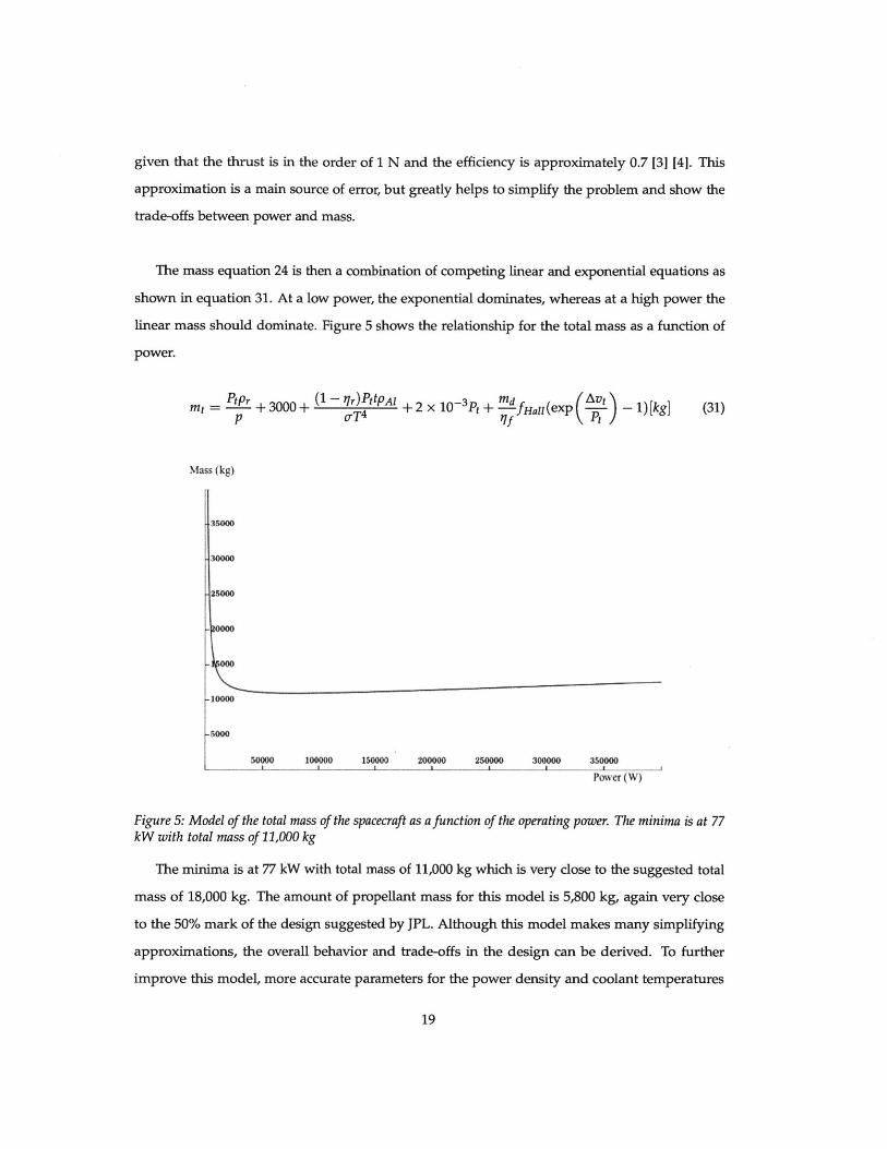
The mass equation 24 is then a combination of competing linear and exponential equations as
shown in equation 31. At a low power, the exponential dominates, whereas at a high power the
linear mass should dominate. Figure 5 shows the relationship for the total mass as a function of
power.
mt =-_r + 3000 + (1 qT)PttPAl+ 2 x 10- 3Pt + -fHall(exp (v-t -1) [kg] (31)p oT 4 I5 Pf
Mass (kg)
35000
-25000
-10000
-5000
50000 100000 15000 200000 250000 300000 30000
Pover (W)
Figure 5: Model of the total mass of the spacecraft as a function of the operating power. The minima is at 77kW with total mass of 11,000 kg
The minima is at 77 kW with total mass of 11,000 kg which is very close to the suggested total
mass of 18,000 kg. The amount of propellant mass for this model is 5,800 kg, again very close
to the 50% mark of the design suggested by JPL. Although this model makes many simplifying
approximations, the overall behavior and trade-offs in the design can be derived. To further
improve this model, more accurate parameters for the power density and coolant temperatures
19
of the reactors have to be made. Furthermore, the mass of the shield (both for the reactor and
the external sources) must be estimated. This correction would increase the total mass of the
spacecraft, making it closer to the proposed value by JPL. However, the mass of the exterior shield
does not depend on the reactor power and the size of reactor shield does not vary significantly
with a marginal increase in power [4].
7.2.2 Choice of Propellant
Historically, common propellant for ion thrusters include cesium, mercury, and xenon [1]. Al-
though initially, most thrusters used cesium and mercury, the corrosive effects of cesium and the
strong toxicity of mercury made these elements hard to use for long missions [3] [1]. Inert gases
are neither corrosive nor explosive posing little risk to the life of the spacecraft or the personnel
loading the propellant tanks [31
Theoretically, as seen in equation 12 , xenon should offer the highest thrust of all the inert
gases due to having the highest mass of the non-radioactive inert gases. However, studies have
been made to show that krypton, another noble gas could be a possible substitute, by trading
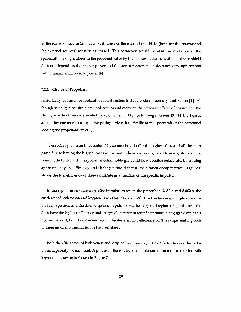
approximately 4% efficiency and slightly reduced thrust, for a much cheaper price . Figure 6
shows the fuel efficiency of three candidate as a function of the specific impulse.
In the region of suggested specific impulse, between the prescribed 6,650 s and 8,000 s, the
,efficiency of both xenon and krypton reach their peaks at 82%. This has two major implications for
the fuel type used and the desired specific impulse. First, the suggested region for specific impulse
does have the highest efficiency and marginal increase in specific impulse is negligible after this
regime. Second, both krypton and xenon display a similar efficiency on this range, making both
of them attractive candidates for long missions.
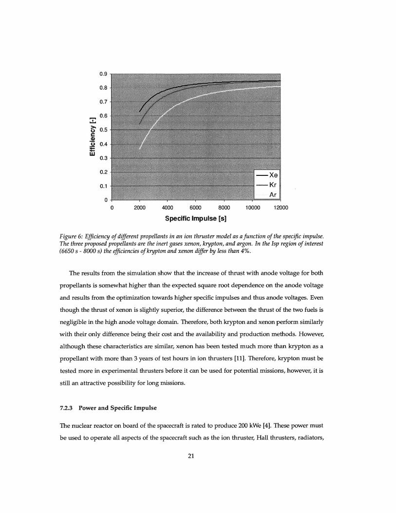
With the efficiencies of both xenon and krypton being similar, the next factor to consider is the
thrust capability for each fuel. A plot from the results of a simulation for an ion thruster for both
krypton and xenon is shown in Figure 7.
20
0.9
0.8
0.7
__ 0.6
C 0.5
4)O 0.4
r=0.3
0.2
0.1 -- Kr
00 2000 4000 6000 8000 10000 12000
Specific Impulse [s]
Figure 6: Efficiency of different propellants in an ion thruster model as a function of the specifc impulse.The three proposed propellants are the inert gases xenon, krypton, and argon. In the Isp region of interest(6650 s - 8000 s) the efficiencies of krypton and xenon differ by less than 4%.
The results from the simulation show that the increase of thrust with anode voltage for both
propellants is somewhat higher than the expected square root dependence on the anode voltage
and results from the optimization towards higher specific impulses and thus anode voltages. Even
though the thrust of xenon is slightly superior, the difference between the thrust of the two fuels is
negligible in the high anode voltage domain. Therefore, both krypton and xenon perform similarly
with their only difference being their cost and the availability and production methods. However,
although these characteristics are similar, xenon has been tested much more than krypton as a
propellant with more than 3 years of test hours in ion thrusters [111. Therefore, krypton must be
tested more in experimental thrusters before it can be used for potential missions, however, it is
still an attractive possibility for long missions.
7.2.3 Power and Specific Impulse
The nuclear reactor on board of the spacecraft is rated to produce 200 kWe [4]. These power must
be used to operate all aspects of the spacecraft such as the ion thruster, Hall thrusters, radiators,
21
Thrust vs. Anode VoltagezE 70-
60-
50-
40-
30-
20-
10- * Krypton= Xenon
0-200 400 600 800 1000 1200
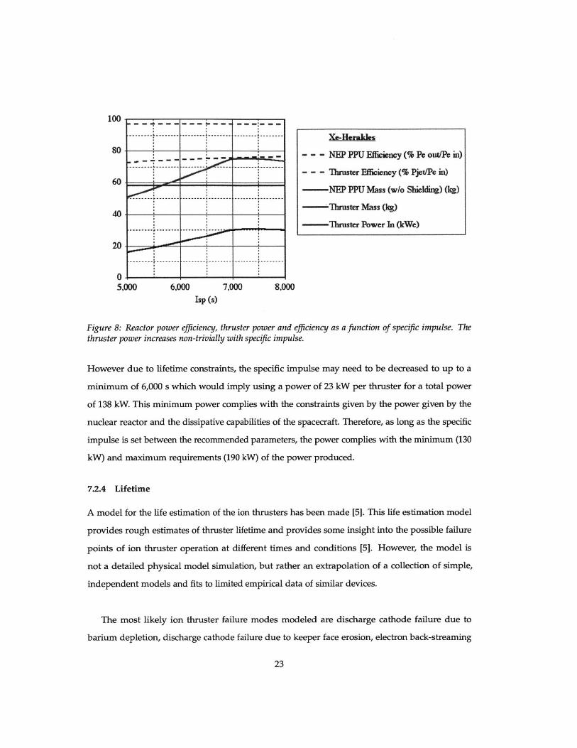
UA/V
Figure 7: Thrust of an ion thruster against the anode voltage for candidate gases krypton and xenon with amass flow rate 1.89 mg/s.The difference in thrust is very small between the two propellants for the sameanode voltage.
control mechanisms, and communications [4]. The ion thrusters are expected to use at most 90%
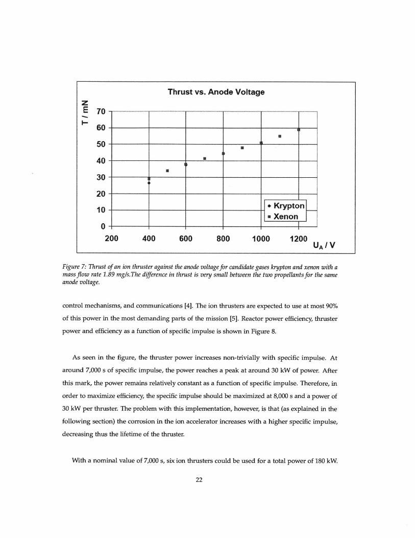
of this power in the most demanding parts of the mission [5]. Reactor power efficiency, thruster
power and efficiency as a function of specific impulse is shown in Figure 8.
As seen in the figure, the thruster power increases non-trivially with specific impulse. At
around 7,000 s of specific impulse, the power reaches a peak at around 30 kW of power. After
this mark, the power remains relatively constant as a function of specific impulse. Therefore, in
order to maximize efficiency, the specific impulse should be maximized at 8,000 s and a power of
30 kW per thruster. The problem with this implementation, however, is that (as explained in the
following section) the corrosion in the ion accelerator increases with a higher specific impulse,
decreasing thus the lifetime of the thruster.
With a nominal value of 7,000 s, six ion thrusters could be used for a total power of 180 kW.
22
100
80
60
40
20
05,000 6,000 7,000 8,000
Isp (s)
Figure 8: Reactor power efficiency, thruster power and efficiency as a function of specific impulse. Thethruster power increases non-trivially with specifc impulse.
However due to lifetime constraints, the specific impulse may need to be decreased to up to a
minimum of 6,000 s which would imply using a power of 23 kW per thruster for a total power
of 138 kW. This minimum power complies with the constraints given by the power given by the
nuclear reactor and the dissipative capabilities of the spacecraft. Therefore, as long as the specific
impulse is set between the recommended parameters, the power complies with the minimum (130
kW) and maximum requirements (190 kW) of the power produced.
7.2.4 Lifetime
A model for the life estimation of the ion thrusters has been made [5]. This life estimation model
provides rough estimates of thruster lifetime and provides some insight into the possible failure
points of ion thruster operation at different times and conditions [5]. However, the model is
not a detailed physical model simulation, but rather an extrapolation of a collection of simple,
independent models and fits to limited empirical data of similar devices.
The most likely ion thruster failure modes modeled are discharge cathode failure due to
barium depletion, discharge cathode failure due to keeper face erosion, electron back-streaming
23
Xe-Herakles
--- NEP PPU Efficiency (% Pe out/Pe in)
- - - Thruster Fficiency (% Pjet/Pc in)
- NEP PPU Mass (w/o Shielding) (kg)
Thruster Mass (kg)
Thruster Power In (kWe)
-------- -------- ........
----------------- ----- -------- --------
--------- -------- .............-------- ----
-------- --------
-------- -------- --------

due to accelerator grid wall erosion, and accelerator grid failure due to pits-and-grooves erosion
on the downstream surface [5]. Other important wear mechanisms have not been modeled, such
as discharge cathode failure due to the formation of coatings on the emitting surface.
At the nominal operating point of a system power of 180 kW at a specific impulse of 7000
s, the life model shows that the thruster will fail at approximately 164,000 hours or roughly 18
years [5]. This lifetime is below the needed requirement of 20 years. Furthermore, no ion thruster
of this power has been tested for more than 3 years continuously [5]. Possible responses to this
setback are to include an emergency set of thrusters, but that would double the cost of the ion
thruster propulsion system. Other solutions involve reducing the specific impulse closer to 6,000
s, thus lowering the corrosion in the accelerator grids with a trade-off of reducing the efficiency
of the fuel. Therefore, further investigation must be done to find ways to extend the lifetime of
ion thrusters such that they are suitable to perform long missions without reducing efficiency of
adding redundant costs.
VIII. CONCLUSION
The purpose of this thesis was to review the physics and evaluate the design electric propulsion
system of Project Prometheus. In order to accomplish this goal, the background physics for
ion thrusters was presented, covering important topics such as thrust, specific impulse, power
efficiency and ion thruster principles.
Using these principles, the design constraints for Project Prometheus as stated by JPL were pre-
sented and discussed. For each of these constraints, the possible design responses were evaluated
by using the results from simulations and experiments performed in similar propulsion systems.
The main design responses that were evaluated were the following: the amount of propellant
mass, the choice of propellant, the specific impulse, and the lifetime of the thrusters.
The maximum amount of propellant that the spacecraft can carry is 18,000 kg. A model that
estimated the dependance of the mass of each component on power was constructed. The results
of this model were similar to the design parameters design by JPL at the optimal point. Several
24

methods, were suggested to improve this model.
The ideal propellant for the mission was xenon due to being inert. However, krypton came as
a close second by having similar efficiency and thrust to xenon and being cheaper to produce. The
lack of empirical testing, however, makes krypton for this mission, but could be considered for
future projects with reduced budget.
The power of the thrusters was found to vary with the specific impulse. For the range between
6,000 s and 8,000 s the total power ranged between 136 kW and 180 kW. These limits complied
with the power requirements by the reactor and the radiator in the spacecraft.
Some initial lifetime tests were simulated for the Herakles thruster. It was found that at 7,000
s of specific impulse, the thruster was not expected to withstand the 20 years required for the
mission. Therefore, future studies must be made to see whether lowering the specific impulse
(and hence sacrificing fuel efficiency) would allow the lifetime of the thrusters to increase.
Overall these results show that Project Prometheus had solid design foundations that would
have allowed for a plausible space mission. However, as the project was cancelled, many of
the unknowns, such as the relation between lifetime and specific impulse, or the plausibility of
krypton being used as propellant for long missions will have to be explored by future projects.
25

IX. REFERENCES
[1] P. J. Wilbur, "Ion thruster development trends and status in the united states," JOURNAL OF
PROPULSION AND POWER Vol. 14, No. 5,1998.
[2] E. Y. Choueiri, "A critical history of electric propulsion: The first 50 years (1906-1956)," Journal
of Propulsion and Power, 2004.
[3] D. M. Goebel, "Fundamentals of electric propulsion: ion and hall thrusters," Hoboken, N.J.:
Wiley, pp. 55-65, 2008.
[4] JPL, "Prometheus project final report," National Aeronautics and Space Administration, pp. 55-65,
2005.
[5] D. Fiehler, "Electric propulsion system modeling for the proposed prometheus 1 mission,"
41st Joint Propulsion Conference and Exhibit, 2005.
[6] S. R. Oleson, "The electric propulsion segment of prometheus 1," 41st AIAA/ASME/SAE/ASEE
Joint Propulsion Conference and Exhibit, pp. 177-185, 2005.
[7] P. J. Wilbur, "An approach to the parametric design of ion thrusters," Journal of Propulsion and
Power, 1990.
[8] H. R. Kaufman, "Technology of electron-bombardment ion thrusters," Journal of Advances in
Electronics and Electron Physics, 1974.
[9] R. A. Knief, "Theory and technology of commercial nuclear power," American Nuclear Society,
2008.
[10] L. Kuguoglu, "Probabilistic structural evaluation of uncertainties in radiator sandwich panel
design," ASCE, 2006.
[11] G. Parissenti, "Non conventional propellants for electric propulsion applications," Space
Propulsion Journal, 2010.
26