ntu-a to pkm-b (7-8-62)
TRANSCRIPT

บริษัท ปตท.สผ. สยาม จาํกัด
ภาคผนวก ข.3 Maintenance Strategy-Bulklines
รายงานผลการปฏบิัติตามมาตรการป้องกันและแก้ไขผลกระทบสิ่งแวดลอ้ม และมาตรการติดตามตรวจสอบผลกระทบสิ่งแวดล้อม โครงการผลิตปิโตรเลียมแหล่งปรือกระเทียม ระยะที่ 2 และพ้ืนที่ใกล้เคียง แปลงเอส 1 จังหวัดกําแพงเพชร พิจิตร และพิษณุโลก
ของบริษัท ปตท.สผ.สยาม จํากัด ฉบับเดือนมกราคม - มิถุนายน พ.ศ.2562


S1.SMNT.MS.M.06 Greater S1 Assets: Bulklines
Rev.04, 18 October 2013 i
UNCONTROLLED when printed and without valid stamp.
Latest version is available on Intranet:
http://s1.pttep.com/apps/vir_assetintegrity/documents//Main%20Doc/SMNT-MS/SMNT-MS-M-06%20Bulklines.pdf
Document Owner: DSF/M
Document Custodian: DSF/M
REVISION HISTORY
Revision Description Issued Date
Next Review
1 New issue Issued after company ownership change
25/03/08
2
Change document No. A72 to SMNT
28/08/09
3
(1) Reformatted from SMNT-MS-M-06: BULKLINES (2) Aligned with new PTTEP SSHE MS, ISO14001:2004 and OHSAS18001:2007 requirement. (3) Updated Organizational Indicators from JGO to DSO.
18/10/10
18/10/13
4 Update inspection strategy
18/10/2013 18/10/2016

S1.SMNT.MS.M.06 Greater S1 Assets: Bulklines
Rev.04, 18 October 2013 1
UNCONTROLLED when printed and without valid stamp.
Latest version is available on Intranet:
http://s1.pttep.com/apps/vir_assetintegrity/documents//Main%20Doc/SMNT-MS/SMNT-MS-M-06%20Bulklines.pdf
COVERAGE
This generic maintenance strategy is written to cover inspection methodology of all the bulklines within PTTEP Siam Limited. The term “bulkline” is defined as pipeline transferred multiphase crude, gas and produced water from well sites to Central Production Station or from well sites to another well sites. The bulklines consist of crude production pipelines (crude, gas and water), water injection pipelines (produced water), main gas lift pipelines (high-pressure gas) and gas production pipelines (wet gas). Equipment covered with this strategy is defined with Equipment Number ‘PL’ in PTTEP Computerized Maintenance Management System (SAP).
OBJECTIVES
The objectives of the maintenance strategy are:
To demonstrate and maintain the technical integrity of (safety critical) assets. To fulfil maintenance activities in the most business-efficient manner by
effective and efficient deployment and use of resources. To improve asset reliability, availability and performance and optimise
maintenance efforts such that company targets in terms of product quantity, quality and unit maintenance cost can be met.
To have in place and operate an auditable system of asset performance and maintenance controls.
To comply with all applicable legislation and company HSE policies. To provide inspection methodology and guideline to inspect and maintain the
technical integrity of NTM-A gas pipelines. To provide pipeline defect assessment guideline to verify their fitness for
services and continuous operation.
REFERENCES
S1.SMNT.PH.00, PTTEP S1 Maintenance Philosophy COR GS 001 External anticorrosion coating for pipelines COR GS 002 Field joint coating for pipelines COR GS 022: Design and installation of external cathodic protection of buried
pipeline. NACE SP0169-2007, Control of External Corrosion on Underground or
Submerged Metallic Piping Systems. ANSI/NACE SP0607-2007/ISO 15589-2 (MOD), Petroleum and natural gas
industries - Cathodic protection of pipeline transportation systems SP0109-2009, Field Application of Bonded Tape Coatings for External Repair,
Rehabilitation, and Weld Joints on Buried Metal Pipelines

S1.SMNT.MS.M.06 Greater S1 Assets: Bulklines
Rev.04, 18 October 2013 2
UNCONTROLLED when printed and without valid stamp.
Latest version is available on Intranet:
http://s1.pttep.com/apps/vir_assetintegrity/documents//Main%20Doc/SMNT-MS/SMNT-MS-M-06%20Bulklines.pdf
TM0497-2012, Measurement Techniques Related to Criteria for Cathodic Protection on Underground or Submerged Metallic Piping Systems
ASME B31G Manual to Determining the Remaining Strength of Corroded Pipelines
ASME B31.4 Pipeline Transportation System for Liquid Hydrocarbon and Other Liquids
ASME B31.8 Gas Transmission and Distribution Piping System. API 579-1/ASME FSS-1 Fitness for Services API 579-2/ASME FSS-2 Fitness for Services Example Manual API 571 Damage mechanism affecting fixed equipment in refinery industry Pipeline defect assessment manual (PDAM). API 570 Piping inspection code, In-service inspection, rating, repair and
alteration of piping system. API 651 Cathodic protection of aboveground storage tank
STRATEGY
In the end of year 2013, there are total 229 bulklines with approximately 506 km in total lengths. The pipelines are not internally coated and passed through block culverts and road crossings. The pipeline section under block culverts and road crossing are externally coated to prevent external corrosion. Some sections of pipelines are laid underground with external coating protection. These pipelines are subject to both internal and external corrosion threats. The water cut in produced oil (currently at 50% average) tends to increase by an introduction of water flooding system also results in an increasing of corrosion rate.
The main inspection methodology will be based on MFL external scanning and ultrasonic thickness measurement (UTM) since external surface of those pipelines can be accessible. Some additional inspection methods are implemented to improve inspection effectiveness and coverage in order to ensure integrity and health of all bulklines.
CORROSION THREATS:
Internal corrosion
CO2 corrosion
Carbon dioxide (CO2) corrosion results when CO2 dissolves in water to form carbonic acid (H2CO3). The acid may lower the pH and sufficient quantities may promote general corrosion and/or pitting corrosion of carbon steel.

S1.SMNT.MS.M.06 Greater S1 Assets: Bulklines
Rev.04, 18 October 2013 3
UNCONTROLLED when printed and without valid stamp.
Latest version is available on Intranet:
http://s1.pttep.com/apps/vir_assetintegrity/documents//Main%20Doc/SMNT-MS/SMNT-MS-M-06%20Bulklines.pdf
Microbiologically Induced Corrosion (MIC)
A form of corrosion caused by living organisms such as bacteria, algae or fungi. It is often associated with the presence of tubercles or slimy organic substances.
Erosion/Erosion-Corrosion
Erosion is the accelerated mechanical removal of surface material as a result of relative movement between, or impact from solids, liquids, vapor or any combination thereof. Erosion-corrosion is a description for the damage that occurs when corrosion contributes to erosion by removing protective films or scales, or by exposing the metal surface to further corrosion under the combined action of erosion and corrosion.
Sulfide stress corrosion cracking (SSC)
Sulfide Stress Cracking (SSC) is defined as cracking of metal under the combined action of tensile stress and corrosion in the presence of water and H2S. SSC is a form of hydrogen stress cracking resulting from absorption of atomic hydrogen that is produced by the sulfide corrosion process on the metal surface.
External corrosion
Soil corrosion
The deterioration of metals exposed to soils is referred to as soil corrosion. The severity of soil corrosion is determined by many factors including operating temperature, moisture and oxygen availability, soil resistivity (soil condition and characteristics), soil type (water drainage), and homogeneity (variation in soil type), cathodic protection, stray current drainage, coating type, age, and condition.
Atmospheric corrosion
A form of corrosion that occurs from moisture associated with atmospheric conditions. Marine environments and moist polluted industrial environments with airborne contaminants are most severe. Dry rural environments cause very little corrosion.
Other treats
External interference by third party activities (i.e. puncture, gouge and dent)
Sabotage and pilferage Natural hazard (land slide, flood, earth quake) Mechanical failure Construction and material defects
S1.SMNT.MS.M.06 Greater S1 Assets: Bulklines
Rev.04, 18 October 2013 4
UNCONTROLLED when printed and without valid stamp.
Latest version is available on Intranet:
http://s1.pttep.com/apps/vir_assetintegrity/documents//Main%20Doc/SMNT-MS/SMNT-MS-M-06%20Bulklines.pdf
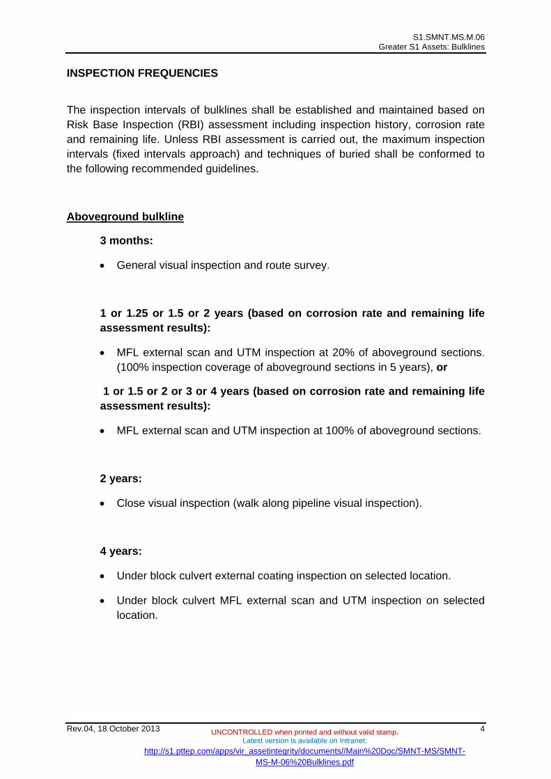
INSPECTION FREQUENCIES
The inspection intervals of bulklines shall be established and maintained based on Risk Base Inspection (RBI) assessment including inspection history, corrosion rate and remaining life. Unless RBI assessment is carried out, the maximum inspection intervals (fixed intervals approach) and techniques of buried shall be conformed to the following recommended guidelines.
Aboveground bulkline
3 months:
General visual inspection and route survey.
1 or 1.25 or 1.5 or 2 years (based on corrosion rate and remaining life assessment results):
MFL external scan and UTM inspection at 20% of aboveground sections. (100% inspection coverage of aboveground sections in 5 years), or
1 or 1.5 or 2 or 3 or 4 years (based on corrosion rate and remaining life assessment results):
MFL external scan and UTM inspection at 100% of aboveground sections.
2 years:
Close visual inspection (walk along pipeline visual inspection).
4 years:
Under block culvert external coating inspection on selected location.
Under block culvert MFL external scan and UTM inspection on selected location.

S1.SMNT.MS.M.06 Greater S1 Assets: Bulklines
Rev.04, 18 October 2013 5
UNCONTROLLED when printed and without valid stamp.
Latest version is available on Intranet:
http://s1.pttep.com/apps/vir_assetintegrity/documents//Main%20Doc/SMNT-MS/SMNT-MS-M-06%20Bulklines.pdf
Underground bulkline
3 month:
Instant-off pipe to soil potential survey. (For cathodic protection bulkline only).
Above-grade visual surveillance.
3 years:
Random excavation and coating removal. Ultrasonic thickness measurement (UTM) inspection.
5 years:
Close Interval potential survey (CIPS) or DC voltage gradient survey (DCVG).
ACCEPTANCE CRITERIA
Instant-off pipe to soil potential survey
After polarization, the instant-off pipe to soil potential of carbon steel buried pipelines shall be
More negative than -850 mV/Cu/CuSO4 in aerated soil
More negative than -950 mV/Cu/CuSO4 for in environment with possible development of sulphate reducing bacteria (de-aerated soil with confirmation of active bacteria presence).
Note: The instant-off pipe to soil potential of pipeline shall not be more negative than -1200 mV to prevent coating disbonding.
Defect assessment
Assessment of corrosion defects shall be conformed to ASME B31G Manual to Determining the Remaining Strength of Corroded Pipelines or recognized international practices i.e. DNV-RP-F101 or RSTRENG. In Level 1 Evaluation, equation of original B31G, modified B31G and DNV-RP-F101 can be used to determine safe operating pressure of corroded pipelines.

S1.SMNT.MS.M.06 Greater S1 Assets: Bulklines
Rev.04, 18 October 2013 6
UNCONTROLLED when printed and without valid stamp.
Latest version is available on Intranet:
http://s1.pttep.com/apps/vir_assetintegrity/documents//Main%20Doc/SMNT-MS/SMNT-MS-M-06%20Bulklines.pdf
Nevertheless, the recommended retirement thickness of pipelines due to corrosion defects (structural retirement thickness – conservative approach) shall be conformed to the followings
Pipeline nominal diameter (inch)
Structural retirement thickness (mm)
3 2.5 4 3.0 6 3.75 8 4.5
10 4.75 12 4.75
Assessment of gouge, dent, girth weld defects and crack shall be conformed to Pipeline defect assessment manual (PDAM). DOCUMETATIONS The following documents shall be maintained for Pipeline safety information (PSI) of Bulklines.
All design documents. All as-built drawings. HAZOP study. RBI study. Pipeline inspection reports including cleaning pig reports. Cathodic protection survey reports, Close Interval potential survey (CIPS) or
DC voltage gradient survey (DCVG) reports.
บริษัท ปตท.สผ. สยาม จาํกัด
ภาคผนวก ข.4 Flowlines and Well Gas Lift Lines
รายงานผลการปฏบิัติตามมาตรการป้องกันและแก้ไขผลกระทบสิ่งแวดลอ้ม และมาตรการติดตามตรวจสอบผลกระทบสิ่งแวดล้อม โครงการผลิตปิโตรเลียมแหล่งปรือกระเทียม ระยะที่ 2 และพ้ืนที่ใกล้เคียง แปลงเอส 1 จังหวัดกําแพงเพชร พิจิตร และพิษณุโลก
ของบริษัท ปตท.สผ.สยาม จํากัด ฉบับเดือนมกราคม - มิถุนายน พ.ศ.2562

PTT Exploration and Production Public Company Limited
PTTEP Procedure
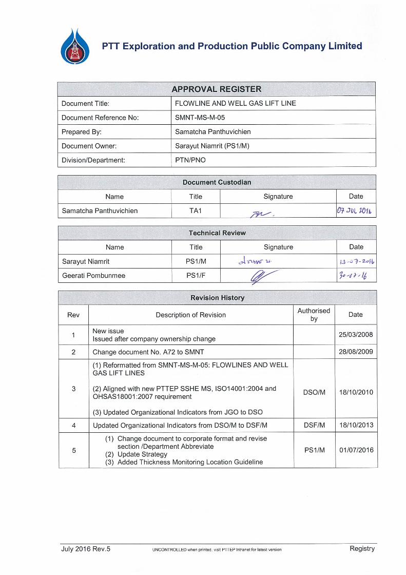
FLOWLINE AND WELL GAS LIFT LINE
Document No: SMNT-MS-M-05
Revision No: 05


FLOWLINE AND WELL GAS LIFT LINE SMNT-MS-M-05
July 2016 Rev.5 UNCONTROLLED when printed, visit PTTEP Intranet for latest version TOC
TABLE OF CONTENTS
1.0 PURPOSE .................................................................................................................... 1
2.0 SCOPE ......................................................................................................................... 1
3.0 REFERENCES ............................................................................................................. 1
4.0 DEFINITIONS ............................................................................................................... 1
5.0 ROLES AND RESPONSIBILITIES .............................................................................. 2
6.0 STRATEGY .................................................................................................................. 2
7.0 APPENDIX ................................................................................................................... 4

FLOWLINE AND WELL GAS LIFT LINE SMNT-MS-M-05
July 2016 Rev.5 UNCONTROLLED when printed, visit PTTEP Intranet for latest version Page 1 of 7
1.0 PURPOSE
The objectives of the maintenance strategy are:
To demonstrate and maintain the technical integrity of (safety critical) assets
To fulfil maintenance activities in the most business-efficient manner by effective and efficient deployment and use of resources
To improve asset reliability, availability and performance and optimise maintenance efforts such that company targets in terms of product quantity, quality and unit maintenance cost can be met
To have in place and operate an auditable system of asset performance and maintenance controls
To comply with all applicable legislation and company SSHE policies
2.0 SCOPE
This generic maintenance strategy is written to cover well flowlines and well gas lift lines in
perimeter of PTTEP Siam, S1 Asset. The term “flowline” is used to define line from wellhead to the first
common manifold including the part of the manifold, which is directly connected to the well (i.e. the
section after the choke valve).
3.0 REFERENCES
3.1 PTTEP CONTROLLING DOCUMENTS
Document Number Document Title
S1.SMNT.PH.00 PTTEP S1 Maintenance Philosophy
EP 2000-5008 Carbon Steel Pipeline Corrosion Engineering Manual
3.2 OTHER REFERENCE DOCUMENTS
Document Number Document Title
API 570 Piping Inspection Code
NACE Standard RP0274-98 High Voltage Electrical Inspection of Pipeline Coating
NACE Standard RP0169-96 Control of External Corrosion on Underground or Submerged Metallic Piping Systems
ASME B31.3 Process Piping
ASME B31.8 Gas Transmission and Distribution Piping System
4.0 DEFINITIONS
Terminology Description
Flowline B31.3 Process piping between wellhead to manifold

FLOWLINE AND WELL GAS LIFT LINE SMNT-MS-M-05
July 2016 Rev.5 UNCONTROLLED when printed, visit PTTEP Intranet for latest version Page 2 of 7
4.1 COMMON ACRONYMS
Set out below are common specific terms presented in alphabetical order:
SAP PTTEP Computerized Maintenance Management System
PI Planned Inspection (Work Order Type)
CI Corrective Inspection (Work Order Type)
5.0 ROLES AND RESPONSIBILITIES
5.1 OWNERSHIP OF THE DOCUMENT: PS1/M
The owner of the document is Superintendent, Maintenance with responsibilities for:
Issuing the FLOWLINE AND WELL GAS LIFT LINE INSPECTION Procedure and its
revisions
Ensuring effective implementation of the procedure
5.2 CUSTODIAN OF THE DOCUMENT: TA1
The custodian of the document is TA1, In-service Inspection and Corrosion with responsibilities for:
Identifying deficiencies or potential improvements
Initiating periodic revision
Maintaining revision history and document status register
6.0 STRATEGY
The need for the regular inspection of flowlines on PTTEP facilities to assure integrity in service
is identified in PTTEP Maintenance Philosophy and also in Statutory Regulations.
6.1 FLOWLINE
In PTTEP the wells are drilled from common well site locations and grouped in manifolds after a
short distance from wellhead.
A. INTERNAL CORROSION
Currently the field operates with low carbon dioxide contents (approx. 1.5% mole) and minor
amount of hydrogen sulphide. The water cut averages at 50% across the field with some wells
producing up to 90% water. With the introduction of the water flooding of the reservoir the water cut will
increase more rapidly than before.
B. SAND EROSION
Some wells are producing high volume of sand and sand erosion takes place at flow direction
change location such as elbow, and tee junction.
C. EXTERNAL CORROSION
A large portion of the flowline is underground. That section is protected against external
corrosion by protective wrapping. No cathodic protection is applied. In some well locations that section
of the flowline is routed through open concrete trench and some have no protective coating, as such
they are more vulnerable to external corrosion.
FLOWLINE AND WELL GAS LIFT LINE SMNT-MS-M-05
July 2016 Rev.5 UNCONTROLLED when printed, visit PTTEP Intranet for latest version Page 3 of 7
6.2 WELL GAS LIFT LINES
A. EXTERNAL CORROSION
Same as well flowlines
B. INTERNAL CORROSION
The lift gas is generally dry. However with the introduction of wet gas wells directly to the gas lift
system there is an increasing risk of internal corrosion.
6.3 INSPECTION FREQUENCIES
Since well fluid condition of each well is changed with hardly to notice and re-evaluate
inspection frequencies on time. Therefore, thickness monitoring frequency of each flowline is 3 monthly
as campaign basis on February, May, August and November.
SAP shall regularly generated PI Work Order of each well site accordingly. Thickness
monitoring location for each flowline and manifold shall be followed Appendix II using Ultrasonic
Thickness Measurement to find minimum thickness of each location.
In case possibility of high wall thickness loss due to well fluid condition changing such as high
sand alert from lab sampling, CI Work Order shall be manually created in SAP for the concerned well to
monitor thickness ASAP.

FLOWLINE AND WELL GAS LIFT LINE SMNT-MS-M-05
July 2016 Rev.5 UNCONTROLLED when printed, visit PTTEP Intranet for latest version Page 4 of 7
7.0 APPENDIX
7.1 APPENDIX I: CALCULATION OF MINIMUM ALLOWABLE PIPING WALL THICKNESS
A. The Final retirement thickness for piping is based on the higher of two thicknesses:
Pressure design thickness under internal pressure - Wall thickness required for pressure
competency can be calculated with the following formula (as per ANSI B31.3)
t = P * D / [2(SE+PY)]
Where
D= Nominal outside diameter of pipe, mm
P= Operating pressure, barg
S= Stress value at design temperature, MPa
E= Quality factor
Y= Coefficient
t= Pressure Design thickness, mm
Wall thickness required to cover other loading on the pipe, besides internal pressure, e.g.
support loading, third party damage, vibration etc., which are very difficult to quantify, often
called the "Structural retirement thickness"
NPS (in) Recommended retirement Thickness (mm)
0.5 - 3 2.50
4 3.00
6 3.75
8 4.50
10 4.75
12 4.75
B. Line standards
A standard well flowline consist of the following sections:
3”- SCH 160 line pipe and elbows, material API 5L Grade B (Yield Strength 241 MPa), from
X-mas tree until the choke valve
3”- SCH 80 line pipe and elbows, material API 5L Grade B, from choke valve to the
manifold
1”- SCH 80 line pipe and elbows, material API 5L Grade B, drain line after choke valve
Gas lift lines are 2” SCH 80 line pipe, material API 5L Grade B
NPS (in) SCH OD (mm) WT (mm)
1 80 33.4 4.55
2 80 60.3 5.54
3 80 88.9 7.62
3 160 88.9 11.13

FLOWLINE AND WELL GAS LIFT LINE SMNT-MS-M-05
July 2016 Rev.5 UNCONTROLLED when printed, visit PTTEP Intranet for latest version Page 5 of 7
7.2 APPENDIX I: THICKNESS MONITORING LOCATION GUIDELINE
Manifold Thickness Monitoring Location

FLOWLINE AND WELL GAS LIFT LINE SMNT-MS-M-05
July 2016 Rev.5 UNCONTROLLED when printed, visit PTTEP Intranet for latest version Page 6 of 7
Crude Flowline Monitoring Location

FLOWLINE AND WELL GAS LIFT LINE SMNT-MS-M-05
July 2016 Rev.5 UNCONTROLLED when printed, visit PTTEP Intranet for latest version Page 7 of 7
Water Flowline Monitoring Location

บริษัท ปตท.สผ. สยาม จาํกัด
ภาคผนวก ข.5 Oil Spill Response Plan
รายงานผลการปฏบิัติตามมาตรการป้องกันและแก้ไขผลกระทบสิ่งแวดลอ้ม และมาตรการติดตามตรวจสอบผลกระทบสิ่งแวดล้อม โครงการผลิตปิโตรเลียมแหล่งปรือกระเทียม ระยะที่ 2 และพ้ืนที่ใกล้เคียง แปลงเอส 1 จังหวัดกําแพงเพชร พิจิตร และพิษณุโลก
ของบริษัท ปตท.สผ.สยาม จํากัด ฉบับเดือนมกราคม - มิถุนายน พ.ศ.2562