nts&ntu series - mean well
TRANSCRIPT

NTS & NTU Series
� �High Reliable Inverter
True Sine Wave Inverter
Installation manual

NTS/NTU series are MEAN WELL's new generation high-reliability off-
g r i d D C - AC p u re s i n e w a ve i n ve r te r s . T h e w h o l e f a m i l y h a s
N T S - 2 5 0 P / 4 0 0 P, N T S - 3 0 0 / 4 5 0 / 7 5 0 / 1 2 0 0 / 1 7 0 0 / 2 2 0 0 / 3 2 0 0 ,
and NTU-1200/1700/2200/3200 series . The whole family of NTS/NTU are
fully digital designed, with three major characteristics of miniaturization,
high efficiency, and intelligence. The main features are, instantaneous
peak load capacity which can reach up to 2 times of output wattage, as
well as AC output voltage/frequency/power saving mode adjustment
capability through the DIP switch of front panel (the idle standby
consumption is 1.5W). It s efficiency reaches up to 93%, and it can be’
operated within temperature range from -25~+70 . Built-in remote℃
control, able to monitor the battery voltage and the load status of the
inverter through IRC1/2/3. Not only intergrated multiple intelligent
p r o t e c t i o n s , b u t a l s o p a s s e d s a f e t y r e g u l a t i o n s s u c h a s
CB/DEKRA/E13/EAC/UL/RCM/FCC/CE/UKCA. Materials and components
are strictly selected and 3-year warranty is provided. It is suitable for
households, vehicles, yacht and remote areas without power grids.
Common application such as, lighting, air conditioning, refrigerators, hair
dryers, microwave ovens , computers, televisions, hand-held power tools,
motor equipment, mobile AC power... etc.

Index
1 Safety Guidelines.
2 Introduction.
2 1 Model number.
2.2 Features
2 3 Main specification.
2.4 Safety Overview
2 5 Derating curve.
2 6 Mechanical specification.
3.Installation & Wiring
3 Precautions.1
3 2. System Block Diagram
3 Installation procedures.3
3.4 Cable selection
3.5 Battery selection
4.User Interface Panel
4.1 AC panel
4.2 DC panel
4 3 LED indicator.
5 Explanation of settings.
5.1 Procedure of Setting
Operating Mode, Output
Voltage, Frequency, and
power Saving Mode
5.2 Function difference
/ /5.3 IRC1 IRC2 IRC3 Remote
control unit
5.4 RS-232 protocol
5 5 UPS mode(only for.
NTU series)
6 Protections and Failure.
Correction
6 1 Protections.
6.2 Failure Correction
7 Warranty.
1
2
2
2
3
16
17
18
23
23
23
24
24
25
26
26
28
29
31
31
32
32
33
39
41
41
41
43
2021 07 Ver 1.2021 07 Ver 1.

1 Safety Guidelines.
� Risk of electrical shock and energy hazard. All failures should be examined
by the qualified technician. Please do not remove the case of the inverter
by yourself.
� Please do not install the inverter in places with high moisture or near
water.
� Please do not install the inverter in places with high ambient temperature
or under direct sunlight.
� Please only connect batteries with the same brand and model number in
one battery bank. Using batteries from different manufacturers or
different capacity is strictly prohibited!
� Never allow a spark or flame in the vicinity of the batteries because they
may ignite explosive gases during normal operation.
� Make sure the air flow from the fan is not obstructed at both sides (front
and back) of the inverter. (Please allow at least 15cm of space)
� Please do not stack any object on the inverter.
� Please do not turn on the inverter before start the engine if inverter
connected to vehicle's battery directly.
1
1
2
2 Introduction.
2.1 Model number
Series name (NTS, NTU)
Rated power (250W~3200W)
AC output voltage (1: 100~120Vac, 2:200~240Vac)
DC Input voltage (12: 12Vdc, 24: 24Vdc, 48: 48Vdc)
AC Socket
(US EU CN AU UK UN GFCI)、 、 、 、 、 、
2
� Full digital design with compact size and light weight.
� True sine wave output(THD<3%)
� Peak power up to 1.7~ 2 times
� AC voltage, frequency, power saving mode selectable.
� Multiple intelligent protections
:DC Input Reverse polarity protection/ Low DC voltage protection/
DC over voltage protection.
:AC Output Short circuit protection, over load protection, over
temperature protection.
� LED indicator Status, DC input, load status, AC input.:
� Built-in Remote control
� Support IRC1/2/3 for 750~3200W models(optional)
� UPS functions( only for NTU series)
� Wide range of DC input voltage for lead acid or lithium battries.
� CB/DEKRA/E13/EAC/UL/RCM/FCC/CE/UKCA certified.
� 3 year warranty
2.2 Features
1 12 USNTS � �300

2.3 Specification
2
3
INPUT
PR
OT
EC
TIO
N
DC
IN
PU
TA
C O
UT
PU
T
MODEL
NTS-250P series
RATED POWER(Continuous)
OVER RATED POWER(3 Min.)
PEAK POWER(10 Sec.)
WAVEFORM
LED STATUS
AC REGULATION
SURGE POWER(30 Cycles)
AC VOLTAGE
FREQUENCY
250W
NTS-250P-112 NTS-250P-124 NTS-250P-148 NTS-250P-212 NTS-250P-224 NTS-250P-248
287.5W
375W
True sine wave (THD<3%)
Please refer to section 3.4 of installation manual
±3.0% at rated input voltage
500W
Default setting set at 110VAC Default setting set at 230VAC
Default setting set at 60Hz 0.1Hz± Default setting set at 50Hz 0.1Hz±
100 / 110 / 115 / 120Vac selectable by DIP S.W 200 / 220 / 230 / 240Vac selectable by DIP S.W
50/60Hz selectable by DIP S.W 50/60Hz selectable by DIP S.W
OUTPUT
BAT. VOLTAGE 12V 24V 48V 12V 24V 48V
Note.1
Note.1
VOLTAGE RANGE (Typ.) 10 ~ 16.5Vdc 10 ~ 16.5Vdc20 ~ 33Vdc 20 ~ 33Vdc40 ~ 66Vdc 40 ~ 66Vdc
DC CURRENT (Typ.) 25A 25A13A 13A7A 7A
10W 10W 12W 10W 10W 12W
Default disable, 1.2W ~ 1.5W by models @ auto detec AC output load 10W will be changed to saving mode≦ ≦
REMOTE CONTROL
DRY CONTACT
OFF MODE CURRENT DRAW <1mA at battery ~DC input must be disconnected
1.2W 1.2W1.3W 1.3W1.5W 1.5W
EFFICIENCY (Typ.)
BATTERY TYPES Lead Acid or li-ion
FUSE (INTERNAL)
LOW
HIGH
BAT. POLARITY
OUTPUT SHORT
OVER TEMPERATURE
OVER LOAD (Typ.)
30A*2 30A*230A*1 30A*110A*2 10A*2
11 0.3Vdc± 11 0.3Vdc±22 0.5Vdc± 22 0.5Vdc±44 1Vdc± 44 1Vdc±
10 0.3Vdc± 10 0.3Vdc±20 0.5Vdc± 20 0.5Vdc±40 1Vdc± 40 1Vdc±
12.5 0.3Vdc± 12.5 0.3Vdc±25 0.5Vdc± 25 0.5Vdc±50 1Vdc± 50 1Vdc±
15.5 0.3Vdc± 15.5 0.3Vdc±31 0.5Vdc± 31 0.5Vdc±62 1Vdc± 62 1Vdc±
16.5 0.3Vdc± 16.5 0.3Vdc±33 0.5Vdc± 33 0.5Vdc±66 1Vdc± 66 1Vdc±
15 0.3Vdc± 15 0.3Vdc±30 0.5Vdc± 30 0.5Vdc±60 1Vdc± 60 1Vdc±
By internal fuse open
Protection type : Shut down o/p voltage, re-power on to recover
Protection type : Shut down o/p voltage, re-power on to recover
105 ~ 115% load for 180 sec., 115% ~ 150% load for 10 sec.
Protection type : Shut down o/p voltage, re-power on to recover
Power ON-OFF remote control by front panel dry contact connector (by RELAY)
Open : Normal work ; Short : Remote offFUNCTION
WORK TEMP. -20 ~ +70 (Refer to “Derating curve”)℃
WORKING HUMIDITY 20 ~ 90% RH non-condensing
STORAGE TEMP., HUMIDITY -30 ~ +70 / -22 ~ +158 F, 10 ~ 95% RH non-condensing℃o
VIBRATION 10 ~ 500Hz, 3G 10min./1cycle, 60min. each along X, Y, Z axes
279K hrs min. Telcordia TR/SR-332 (Bellcore) ; 84K hrs min. MIL-HDBK-217F (25 )℃
186*100.5*32mm (L*W*H)
0.75Kg; 18pcs/ 14.5Kg/ 0.97CUFT
ENVIRON-
MENT
MTBF
DIMENSION
PACKING
OTHER
ALARM
ALARM
SHUTDOWN
SHUTDOWN
RESTART
RESTART
NO LOAD
DISSPATION
(Typ.)
NON-SAVING MODE
SAVING MODE
91% 91% 92% 92% 93% 93%
2
4
MODEL
RATED POWER(Continuous)
OVER RATED POWER(3 Min.)
PEAK POWER(10 Sec.)
WAVEFORM
LED STATUS
AC REGULATION
SURGE POWER(30 Cycles)
AC VOLTAGE
FREQUENCY
400W
NTS-400P-112 NTS-400P-124 NTS-400P-148 NTS-400P-212 NTS-400P-224 NTS-400P-248
460W
600W
True sine wave (THD<3%)
Please refer to section 3.4 of installation manual
±3.0% at rated input voltage
800W
Default setting set at 110VAC Default setting set at 230VAC
Default setting set at 60Hz 0.1Hz± Default setting set at 50Hz 0.1Hz±
100 / 110 / 115 / 120Vac selectable by DIP S.W 200 / 220 / 230 / 240Vac selectable by DIP S.W
50/60Hz selectable by DIP S.W 50/60Hz selectable by DIP S.W
OUTPUT
Note.1
PR
OT
EC
TIO
N
DC
IN
PU
TA
C O
UT
PU
T
BAT. VOLTAGE 12V 24V 48V 12V 24V 48V
Note.1
VOLTAGE RANGE (Typ.) 10 ~ 16.5Vdc 10 ~ 16.5Vdc20 ~ 33Vdc 20 ~ 33Vdc40 ~ 66Vdc 40 ~ 66Vdc
DC CURRENT (Typ.) 40A 40A20A 20A10A 10A
OFF MODE CURRENT DRAW <1mA at battery ~DC input must be disconnected
EFFICIENCY (Typ.)
BATTERY TYPES Lead Acid or li-ion
FUSE (INTERNAL)
LOW
HIGH
BAT. POLARITY
OUTPUT SHORT
OVER TEMPERATURE
OVER LOAD (Typ.)
40A*2 40A*230A*2 30A*210A*2 10A*2
11 0.3Vdc± 11 0.3Vdc±22 0.5Vdc± 22 0.5Vdc±44 1Vdc± 44 1Vdc±
10 0.3Vdc± 10 0.3Vdc±20 0.5Vdc± 20 0.5Vdc±40 1Vdc± 40 1Vdc±
12.5 0.3Vdc± 12.5 0.3Vdc±25 0.5Vdc± 25 0.5Vdc±50 1Vdc± 50 1Vdc±
15.5 0.3Vdc± 15.5 0.3Vdc±31 0.5Vdc± 31 0.5Vdc±62 1Vdc± 62 1Vdc±
16.5 0.3Vdc± 16.5 0.3Vdc±33 0.5Vdc± 33 0.5Vdc±66 1Vdc± 66 1Vdc±
15 0.3Vdc± 15 0.3Vdc±30 0.5Vdc± 30 0.5Vdc±60 1Vdc± 60 1Vdc±
By internal fuse open
Protection type : Shut down o/p voltage, re-power on to recover
Protection type : Shut down o/p voltage, re-power on to recover
105 ~ 115% load for 180 sec., 115% ~ 150% load for 10 sec.
Protection type : Shut down o/p voltage, re-power on to recover
Power ON-OFF remote control by front panel dry contact connector (by RELAY)
Open : Normal work ; Short : Remote offFUNCTION
WORK TEMP. -20 ~ +70 (Refer to “Derating curve”)℃
WORKING HUMIDITY 20 ~ 90% RH non-condensing
STORAGE TEMP., HUMIDITY -30 ~ +70 / -22 ~ +158 F, 10 ~ 95% RH non-condensing℃o
VIBRATION 10 ~ 500Hz, 3G 10min./1cycle, 60min. each along X, Y, Z axes
278.7K hrs min. Telcordia TR/SR-332 (Bellcore) ; 84K hrs min. MIL-HDBK-217F (25 )℃
186*100.5*32mm (L*W*H)
0.75Kg; 18pcs/ 14.5Kg/ 0.97CUFT
ENVIRON-
MENT
MTBF
DIMENSION
PACKING
OTHER
ALARM
ALARM
SHUTDOWN
SHUTDOWN
RESTART
RESTART
INPUT
10W 10W 12W 10W 10W 12W
1.2W 1.2W1.3W 1.3W1.5W 1.5W
NO LOAD
DISSPATION
(Typ.)
NON-SAVING MODE
SAVING MODE
REMOTE CONTROL
DRY CONTACT
NTS-400P series
Default disable, 1.2W ~ 1.5W by models @ auto detec AC output load 10W will be changed to saving mode≦ ≦
89% 91% 91% 91% 93% 93%

�
2
MODEL
RATED POWER(Continuous)
OVER RATED POWER(3 Min.)
PEAK POWER(10 Sec.)
WAVEFORM
FRONT PANEL LED
AC REGULATION
SURGE POWER(30 Cycles)
AC VOLTAGE
FREQUENCY
300W
NTS-300-112 NTS-300-124 NTS-300-148 NTS-300-212 NTS-300-224 NTS-300-248
345W
450W
True sine wave (THD<3%)
Please refer to section 3.4 of installation manual
±3.0% at rated input voltage
600W
Default setting set at 110VAC Default setting set at 230VAC
Default setting set at 60Hz 0.1Hz± Default setting set at 50Hz 0.1Hz±
100 / 110 / 115 / 120Vac selectable by DIP S.W 200 / 220 / 230 / 240Vac selectable by DIP S.W
50/60Hz selectable by DIP S.W 50/60Hz selectable by DIP S.W
OUTPUT
Note.1
= US, GFCI, UN = EU, CN, AU, UK, UN
INPUT
PR
OT
EC
TIO
N DC
IN
PU
TA
C O
UT
PU
T
BAT. VOLTAGE 12V 24V 48V 12V 24V 48V
Note.1
VOLTAGE RANGE (Typ.) 10 ~ 16.5Vdc 10 ~ 16.5Vdc20 ~ 33Vdc 20 ~ 33Vdc40 ~ 66Vdc 40 ~ 66Vdc
DC CURRENT (Typ.) 30A 30A15A 15A8A 8A
10W 10W 12W 10W 10W 12W
OFF MODE CURRENT DRAW ≦1mA
1.2W 1.2W1.3W 1.3W1.5W 1.5W
EFFICIENCY (Typ.)
BATTERY TYPES Lead Acid or li-ion
FUSE (INTERNAL)
LOW
HIGH
BAT. POLARITY
OUTPUT SHORT
OVER TEMPERATURE
OVER LOAD (Typ.)
GFCI PROCTECTION
30A*2 30A*230A*1 30A*110A*2 10A*2
11 0.3Vdc± 11 0.3Vdc±22 0.5Vdc± 22 0.5Vdc±44 1Vdc± 44 1Vdc±
10 0.3Vdc± 10 0.3Vdc±20 0.5Vdc± 20 0.5Vdc±40 1Vdc± 40 1Vdc±
12.5 0.3Vdc± 12.5 0.3Vdc±25 0.5Vdc± 25 0.5Vdc±50 1Vdc± 50 1Vdc±
15.5 0.3Vdc± 15.5 0.3Vdc±31 0.5Vdc± 31 0.5Vdc±62 1Vdc± 62 1Vdc±
16.5 0.3Vdc± 16.5 0.3Vdc±33 0.5Vdc± 33 0.5Vdc±66 1Vdc± 66 1Vdc±
15 0.3Vdc± 15 0.3Vdc±30 0.5Vdc± 30 0.5Vdc±60 1Vdc±
None
60 1Vdc±
By internal fuse open
Protection type : Shut down o/p voltage, re-power on to recover
Protection type : Shut down o/p voltage, re-power on to recover
105 ~ 115% load for 180 sec., 115% ~ 150% load for 10 sec.
Protection type : Shut down o/p voltage, re-power on to recover
Power ON-OFF remote control by front panel dry contact connector (by RELAY)
Open : Normal work ; Short : Remote offFUNCTION
WORK TEMP. -25 ~ +65 (Refer to “Derating curve”)℃
WORKING HUMIDITY 20 ~ 90% RH non-condensing
STORAGE TEMP., HUMIDITY -30 ~ +70 / -22 ~ +158 F, 10 ~ 95% RH non-condensing℃o
VIBRATION 10 ~ 500Hz, 3G 10min./1cycle, 60min. each along X, Y, Z axes
281.9K hrs min. Telcordia TR/SR-332 (Bellcore) ; 85.3K hrs min. MIL-HDBK-217F (25 )℃
210*130*55mm (L*W*H)
1.3Kg; 8pcs/ 11.4Kg/ 1.74CUFT
ENVIRON-
MENT
MTBF
DIMENSION
PACKING
OTHER
ALARM
ALARM
SHUTDOWN
SHUTDOWN
RESTART
RESTART
NO LOAD
DISSPATION
(Typ.)
NON-SAVING MODE
SAVING MODE
Design refer to UL458
(Only for “GFCI” AC socket , by request)
REMOTE CONTROL
DRY CONTACT
NTS-300 series
Default disable, 1.2W ~ 1.5W by models @ auto detec AC output load 10W will be changed to saving mode≦ ≦
90% 92% 92% 92% 93% 93%
6
2
MODEL
RATED POWER(Continuous)
OVER RATED POWER(3 Min.)
PEAK POWER(10 Sec.)
WAVEFORM
FRONT PANEL LED
AC REGULATION
SURGE POWER(30 Cycles)
AC VOLTAGE
450W
NTS-450-112 NTS-450-124 NTS-450-148 NTS-450-212 NTS-450-224 NTS-450-248
517.5W
675W
True sine wave (THD<3%)
Please refer to section 3.4 of installation manual
±3.0% at rated input voltage
900W
Default setting set at 110VAC Default setting set at 230VAC
100 / 110 / 115 / 120Vac selectable by DIP S.W 200 / 220 / 230 / 240Vac selectable by DIP S.W
Note.1
= US, GFCI, UN = EU, CN, AU, UK, UN
INPUT
PR
OT
EC
TIO
N DC
IN
PU
TA
C O
UT
PU
T
BAT. VOLTAGE 12V 24V 48V 12V 24V 48V
Note.1
VOLTAGE RANGE (Typ.) 10 ~ 16.5Vdc 10 ~ 16.5Vdc20 ~ 33Vdc 20 ~ 33Vdc40 ~ 66Vdc 40 ~ 66Vdc
DC CURRENT (Typ.) 50A 50A25A 25A14A 14A
10W 10W 12W 10W 10W 12W
OFF MODE CURRENT DRAW ≦1mA
1.2W 1.2W1.3W 1.3W1.5W 1.5W
EFFICIENCY (Typ.)
BATTERY TYPES Lead Acid or li-ion
FUSE (INTERNAL)
LOW
HIGH
BAT. POLARITY
OUTPUT SHORT
OVER TEMPERATURE
OVER LOAD (Typ.)
GFCI PROCTECTION
40A*2 40A*240A*1 40A*110A*2 10A*2
11 0.3Vdc± 11 0.3Vdc±22 0.5Vdc± 22 0.5Vdc±44 1Vdc± 44 1Vdc±
10 0.3Vdc± 10 0.3Vdc±20 0.5Vdc± 20 0.5Vdc±40 1Vdc± 40 1Vdc±
12.5 0.3Vdc± 12.5 0.3Vdc±25 0.5Vdc± 25 0.5Vdc±50 1Vdc± 50 1Vdc±
15.5 0.3Vdc± 15.5 0.3Vdc±31 0.5Vdc± 31 0.5Vdc±62 1Vdc± 62 1Vdc±
16.5 0.3Vdc± 16.5 0.3Vdc±33 0.5Vdc± 33 0.5Vdc±66 1Vdc± 66 1Vdc±
15 0.3Vdc± 15 0.3Vdc±30 0.5Vdc± 30 0.5Vdc±60 1Vdc±
None
60 1Vdc±
By internal fuse open
Protection type : Shut down o/p voltage, re-power on to recover
Protection type : Shut down o/p voltage, re-power on to recover
105 ~ 115% load for 180 sec., 115% ~ 150% load for 10 sec.
Protection type : Shut down o/p voltage, re-power on to recover
Power ON-OFF remote control by front panel dry contact connector (by RELAY)
Open : Normal work ; Short : Remote offFUNCTION
WORK TEMP. -25 ~ +70 (Refer to “Derating curve”)℃
WORKING HUMIDITY 20 ~ 90% RH non-condensing
STORAGE TEMP., HUMIDITY -30 ~ +70 / -22 ~ +158 F, 10 ~ 95% RH non-condensing℃o
VIBRATION 10 ~ 500Hz, 3G 10min./1cycle, 60min. each along X, Y, Z axes
281.3K hrs min. Telcordia TR/SR-332 (Bellcore) ; 85K hrs min. MIL-HDBK-217F (25 )℃
210*130*55mm (L*W*H)
1.3Kg; 8pcs/ 11.4Kg/ 1.74CUFT
ENVIRON-
MENT
MTBF
DIMENSION
PACKING
OTHER
ALARM
ALARM
SHUTDOWN
SHUTDOWN
RESTART
RESTART
NO LOAD
DISSPATION
(Typ.)
NON-SAVING MODE
SAVING MODE
Design refer to UL458
(Only for “GFCI” AC socket , by request)
Default setting set at 60Hz 0.1Hz± Default setting set at 50Hz 0.1Hz±
50/60Hz selectable by DIP S.W 50/60Hz selectable by DIP S.WFREQUENCY
OUTPUT
REMOTE CONTROL
DRY CONTACT
NTS-450 series
Default disable, 1.2W ~ 1.5W by models @ auto detec AC output load 10W will be changed to saving mode≦ ≦
88% 91% 91% 90% 93% 93%

7
2
MODEL
RATED POWER(Continuous)
OVER RATED POWER(3 Min.)
PEAK POWER(10 Sec.)
WAVEFORM
FRONT PANEL LED
AC REGULATION
SURGE POWER(30 Cycles)
AC VOLTAGE
FREQUENCY
750W
NTS-750-112 NTS-750-124 NTS-750-148 NTS-750-212 NTS-750-224 NTS-750-248
862.5W
1125W
True sine wave (THD<3%)
Please refer to section 3.4 of installation manual
±3.0% at rated input voltage
1500W
Default setting set at 110VAC Default setting set at 230VAC
Default setting set at 60 0.1Hz± Default setting set at 50Hz 0.1Hz±
100 / 110 / 115 / 120Vac selectable by DIP S.W 200 / 220 / 230 / 240Vac selectable by DIP S.W
50/60Hz selectable by DIP S.W 50/60Hz selectable by DIP S.W
OUTPUT
Note.1
= US, GFCI, UN = EU, CN, AU, UK, UN
INPUT
BAT. VOLTAGE 12V 24V 48V 12V 24V 48V
Note.1
VOLTAGE RANGE (Typ.) 10 ~ 16.5Vdc 10 ~ 16.5Vdc20 ~ 33Vdc 20 ~ 33Vdc40 ~ 66Vdc 40 ~ 66Vdc
DC CURRENT (Typ.) 75A 75A38A 38A19A 19A
10W 10W 12W 10W 10W 12W
OFF MODE CURRENT DRAW ≦1mA
1.2W 1.2W1.4W 1.4W1.5W 1.5W
EFFICIENCY (Typ.)
BATTERY TYPES Lead Acid or li-ion
NO LOAD
DISSPATION
(Typ.)
NON-SAVING MODE
SAVING MODE
NTS-750 seriesP
RO
TE
CT
ION DC
IN
PU
TA
C O
UT
PU
T
FUSE (INTERNAL)
LOW
HIGH
BAT. POLARITY
OUTPUT SHORT
OVER TEMPERATURE
OVER LOAD (Typ.)
GFCI PROCTECTION
40A*3 40A*340A*2 40A*225A*2 25A*2
11 0.3Vdc± 11 0.3Vdc±22 0.5Vdc± 22 0.5Vdc±44 1Vdc± 44 1Vdc±
10 0.3Vdc± 10 0.3Vdc±20 0.5Vdc± 20 0.5Vdc±40 1Vdc± 40 1Vdc±
12.5 0.3Vdc± 12.5 0.3Vdc±25 0.5Vdc± 25 0.5Vdc±50 1Vdc± 50 1Vdc±
15.5 0.3Vdc± 15.5 0.3Vdc±31 0.5Vdc± 31 0.5Vdc±62 1Vdc± 62 1Vdc±
16.5 0.3Vdc± 16.5 0.3Vdc±33 0.5Vdc± 33 0.5Vdc±66 1Vdc± 66 1Vdc±
15 0.3Vdc± 15 0.3Vdc±30 0.5Vdc± 30 0.5Vdc±60 1Vdc±
None
60 1Vdc±
By internal fuse open
Protection type : Shut down o/p voltage, re-power on to recover
Protection type : Shut down o/p voltage, re-power on to recover
105 ~ 115% load for 180 sec., 115% ~ 150% load for 10 sec.
Protection type : Shut down o/p voltage, re-power on to recover
Power ON-OFF remote control by front panel dry contact connector (by RELAY)
Open : Normal work ; Short : Remote off
Remote controller sold separately, Order No.: IRC1,IRC2,IRC3
FUNCTION
WORK TEMP. -25 ~ +70 (Refer to “Derating curve”)℃
WORKING HUMIDITY 20 ~ 90% RH non-condensing
STORAGE TEMP., HUMIDITY -30 ~ +70 / -22 ~ +158 F, 10 ~ 95% RH non-condensing℃o
VIBRATION 10 ~ 500Hz, 3G 10min./1cycle, 60min. each along X, Y, Z axes
238.6K hrs min. Telcordia TR/SR-332 (Bellcore) ; 78K hrs min. MIL-HDBK-217F (25 )℃
270*158*67mm (L*W*H)
2.3Kg; 4pcs/ 10.2Kg/ 1.77CUFT
ENVIRON-
MENT
MTBF
DIMENSION
PACKING
OTHER
ALARM
ALARM
SHUTDOWN
SHUTDOWN
RESTART
RESTART
UL458 (Only for “GFCI”
AC socket , by request)
REMOTE CONTROL
DRY CONTACT
Default disable, 1.2W ~ 1.5W by models @ auto detec AC output load 10W will be changed to saving mode≦ ≦
89% 90% 91% 91% 93% 93%
8
2
MODEL
RATED POWER(Continuous)
OVER RATED POWER(3 Min.)
PEAK POWER(10 Sec.)
WAVEFORM
FRONT PANEL LED
AC REGULATION
SURGE POWER(30 Cycles)
AC VOLTAGE
FREQUENCY
1200W
NTS-1200-112 NTS-1200-124 NTS-1200-148 NTS-1200-212 NTS-1200-224 NTS-1200-248
1380W
1800W
True sine wave (THD<3%)
Please refer to section 3.4 of installation manual
±3.0% at rated input voltage
2000W
Default setting set at 110VAC Default setting set at 230VAC
Default setting set at 60 0.1Hz± Default setting set at 50Hz 0.1Hz±
100 / 110 / 115 / 120Vac selectable by DIP S.W 200 / 220 / 230 / 240Vac selectable by DIP S.W
50/60Hz selectable by DIP S.W 50/60Hz selectable by DIP S.W
OUTPUT
Note.1
= US, GFCI, UN = EU, CN, AU, UK, UN
INPUT
BAT. VOLTAGE 12V 24V 48V 12V 24V 48V
Note.1
VOLTAGE RANGE (Typ.) 10 ~ 16.5Vdc 10 ~ 16.5Vdc20 ~ 33Vdc 20 ~ 33Vdc40 ~ 66Vdc 40 ~ 66Vdc
DC CURRENT (Typ.) 120A 120A60A 60A30A 30A
15W 25W
Default disable, auto detec AC output load 10W will be changed to saving mode≦
OFF MODE CURRENT DRAW ≦1mA
1.2W 1.2W1.4W 1.4W1.5W 1.5W
EFFICIENCY (Typ.) 89% 90% 91% 90% 92% 93%
BATTERY TYPES Lead Acid or li-ion
NO LOAD
DISSPATION
(Typ.)
NON-SAVING MODE
SAVING MODE
NTS-1200 series
PR
OT
EC
TIO
N
DC
IN
PU
TA
C O
UT
PU
T
FUSE (INTERNAL)
LOW
HIGH
BAT. POLARITY
CIRCUIT BREAKER
OUTPUT SHORT
OVER TEMPERATURE
OVER LOAD (Typ.)
GFCI PROCTECTION
40A*4 40A*440A*2 40A*225A*2 25A*2
11 0.3Vdc± 11 0.3Vdc±22 0.5Vdc± 22 0.5Vdc±44 1Vdc± 44 1Vdc±
10 0.3Vdc± 10 0.3Vdc±20 0.5Vdc± 20 0.5Vdc±40 1Vdc± 40 1Vdc±
12.5 0.3Vdc± 12.5 0.3Vdc±25 0.5Vdc± 25 0.5Vdc±50 1Vdc± 50 1Vdc±
15.5 0.3Vdc± 15.5 0.3Vdc±31 0.5Vdc± 31 0.5Vdc±62 1Vdc± 62 1Vdc±
16.5 0.3Vdc± 16.5 0.3Vdc±33 0.5Vdc± 33 0.5Vdc±66 1Vdc± 66 1Vdc±
15 0.3Vdc± 15 0.3Vdc±30 0.5Vdc± 30 0.5Vdc±60 1Vdc±
None
60 1Vdc±
By internal fuse open
15A 10A
Protection type : Shut down o/p voltage, re-power on to recover
Protection type : Shut down o/p voltage, re-power on to recover
105 ~ 115% load for 180 sec., 115% ~ 150% load for 10 sec.
Protection type : Shut down o/p voltage, re-power on to recover
Power ON-OFF remote control by front panel dry contact connector (by RELAY)
Open : Normal work ; Short : Remote off
Remote controller sold separately, Order No.: IRC1,IRC2,IRC3
FUNCTION
WORK TEMP. -25 ~ +70 (Refer to “Derating curve”)℃
WORKING HUMIDITY 20 ~ 90% RH non-condensing
STORAGE TEMP., HUMIDITY -30 ~ +70 / -22 ~ +158 F, 10 ~ 95% RH non-condensing℃o
VIBRATION 10 ~ 500Hz, 3G 10min./1cycle, 60min. each along X, Y, Z axes
333*184*70mm (L*W*H)
3.3Kg; 2pcs/ 7.6Kg/ 1.16CUFT
ENVIRON-
MENT
MTBF
DIMENSION
PACKING
OTHER
ALARM
ALARM
SHUTDOWN
SHUTDOWN
RESTART
RESTART
UL458 (Only for “GFCI” AC socket)
REMOTE CONTROL
DRY CONTACT
198.9K hrs min. Telcordia TR/SR-332 (Bellcore) ; 62.0K hrs min. MIL-HDBK-217F (25 )℃
2
9
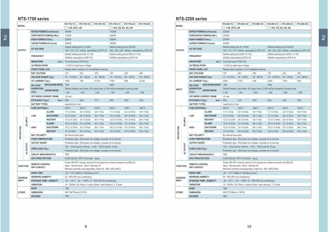
NTS-1700 series
15W 25W
Default disable, auto detec AC output load 10W will be changed to saving mode≦
1.2W 1.2W1.4W 1.4W1.5W 1.5W
NO LOAD
DISSPATION
(Typ.)
NON-SAVING MODE
SAVING MODE
MODEL
RATED POWER(Continuous)
OVER RATED POWER(3 Min.)
PEAK POWER(10 Sec.)
WAVEFORM
FRONT PANEL LED
AC REGULATION
SURGE POWER(30 Cycles)
AC VOLTAGE
FREQUENCY
1500W 1700W
NTS-1700-112 NTS-1700-124 NTS-1700-148 NTS-1700-212 NTS-1700-224 NTS-1700-248
1750W 2000W
2250W 2550W
True sine wave (THD<3%)
Please refer to section 3.4 of installation manual
±3.0% at rated input voltage
3000W 3400W
Default setting set at 110VAC Default setting set at 230VAC
Default setting set at 60 0.1Hz± Default setting set at 50Hz 0.1Hz±
100 / 110 / 115 / 120Vac selectable by DIP S.W 200 / 220 / 230 / 240Vac selectable by DIP S.W
50/60Hz selectable by DIP S.W 50/60Hz selectable by DIP S.W
OUTPUT
Note.1
= US, GFCI, UN = EU, CN, AU, UK, UN
INPUT
DC
IN
PU
T
BAT. VOLTAGE 12V 24V 48V 12V 24V 48V
Note.1
VOLTAGE RANGE (Typ.) 10 ~ 16.5Vdc 10 ~ 16.5Vdc20 ~ 33Vdc 20 ~ 33Vdc40 ~ 66Vdc 40 ~ 66Vdc
DC CURRENT (Typ.) 150A 170A75A 85A37.5A 42.5A
OFF MODE CURRENT DRAW ≦1mA
EFFICIENCY (Typ.) 89% 90% 91% 90% 92% 93%
BATTERY TYPES Lead Acid or li-ion
FUSE (INTERNAL)
LOW
HIGH
BAT. POLARITY
OUTPUT SHORT
OVER TEMPERATURE
OVER LOAD (Typ.)
40A*5 40A*530A*3 30A*330A*2 30A*2
11 0.3Vdc± 11 0.3Vdc±22 0.5Vdc± 22 0.5Vdc±44 1Vdc± 44 1Vdc±
10 0.3Vdc± 10 0.3Vdc±20 0.5Vdc± 20 0.5Vdc±40 1Vdc± 40 1Vdc±
12.5 0.3Vdc± 12.5 0.3Vdc±25 0.5Vdc± 25 0.5Vdc±50 1Vdc± 50 1Vdc±
15.5 0.3Vdc± 15.5 0.3Vdc±31 0.5Vdc± 31 0.5Vdc±62 1Vdc± 62 1Vdc±
16.5 0.3Vdc± 16.5 0.3Vdc±33 0.5Vdc± 33 0.5Vdc±66 1Vdc± 66 1Vdc±
15 0.3Vdc± 15 0.3Vdc±30 0.5Vdc± 30 0.5Vdc±60 1Vdc± 60 1Vdc±
By internal fuse open
Protection type : Shut down o/p voltage, re-power on to recover
Protection type : Shut down o/p voltage, re-power on to recover
105 ~ 115% load for 180 sec., 115% ~ 150% load for 10 sec.
Protection type : Shut down o/p voltage, re-power on to recover
ALARM
ALARM
SHUTDOWN
SHUTDOWN
RESTART
RESTART
PR
OT
EC
TIO
N
AC
OU
TP
UT
GFCI PROCTECTION None
Power ON-OFF remote control by front panel dry contact connector (by RELAY)
Open : Normal work ; Short : Remote off
Remote controller sold separately, Order No.: IRC1,IRC2,IRC3
FUNCTION
WORK TEMP. -20 ~ +70 (Refer to “Derating curve”)℃
WORKING HUMIDITY 20 ~ 90% RH non-condensing
STORAGE TEMP., HUMIDITY -30 ~ +70 / -22 ~ +158 F, 10 ~ 95% RH non-condensing℃o
VIBRATION 10 ~ 500Hz, 3G 10min./1cycle, 60min. each along X, Y, Z axes
TBD
400*184*70mm (L*W*H)
TBD
ENVIRON-
MENT
MTBF
DIMENSION
PACKING
OTHER
UL458 (Only for “GFCI” AC socket)
REMOTE CONTROL
DRY CONTACT
CIRCUIT BREAKER(GFCI) TBD
10
2
NTS-2200 series
15W 25W
Default disable, auto detec AC output load 10W will be changed to saving mode≦
1.2W 1.2W1.4W 1.4W1.5W 1.5W
NO LOAD
DISSPATION
(Typ.)
NON-SAVING MODE
SAVING MODE
MODEL
RATED POWER(Continuous)
OVER RATED POWER(3 Min.)
PEAK POWER(10 Sec.)
WAVEFORM
FRONT PANEL LED
AC REGULATION
SURGE POWER(30 Cycles)
AC VOLTAGE
FREQUENCY
2200W
NTS-2200-112 NTS-2200-124 NTS-2200-148 NTS-2200-212 NTS-2200-224 NTS-2200-248
2530W
2750W
True sine wave (THD<3%)
Please refer to section 3.4 of installation manual
±3.0% at rated input voltage
4400W
Default setting set at 110VAC Default setting set at 230VAC
Default setting set at 60 0.1Hz± Default setting set at 50Hz 0.1Hz±
100 / 110 / 115 / 120Vac selectable by DIP S.W 200 / 220 / 230 / 240Vac selectable by DIP S.W
50/60Hz selectable by DIP S.W 50/60Hz selectable by DIP S.W
OUTPUT
Note.1
= US, GFCI, UN = EU, CN, AU, UK, UN
INPUT
DC
IN
PU
T
BAT. VOLTAGE 12V 24V 48V 12V 24V 48V
Note.1
VOLTAGE RANGE (Typ.) 10 ~ 16.5Vdc 10 ~ 16.5Vdc20 ~ 33Vdc 20 ~ 33Vdc40 ~ 66Vdc 40 ~ 66Vdc
DC CURRENT (Typ.) 220A 220A110A 110A55A 55A
OFF MODE CURRENT DRAW ≦1mA
EFFICIENCY (Typ.) 89% 91% 92% 90% 92% 93%
BATTERY TYPES Lead Acid or li-ion
FUSE (INTERNAL)
LOW
HIGH
BAT. POLARITY
OUTPUT SHORT
OVER TEMPERATURE
OVER LOAD (Typ.)
40A*5 40A*530A*3 30A*330A*2 30A*2
11 0.3Vdc± 11 0.3Vdc±22 0.5Vdc± 22 0.5Vdc±44 1Vdc± 44 1Vdc±
10 0.3Vdc± 10 0.3Vdc±20 0.5Vdc± 20 0.5Vdc±40 1Vdc± 40 1Vdc±
12.5 0.3Vdc± 12.5 0.3Vdc±25 0.5Vdc± 25 0.5Vdc±50 1Vdc± 50 1Vdc±
15.5 0.3Vdc± 15.5 0.3Vdc±31 0.5Vdc± 31 0.5Vdc±62 1Vdc± 62 1Vdc±
16.5 0.3Vdc± 16.5 0.3Vdc±33 0.5Vdc± 33 0.5Vdc±66 1Vdc± 66 1Vdc±
15 0.3Vdc± 15 0.3Vdc±30 0.5Vdc± 30 0.5Vdc±60 1Vdc± 60 1Vdc±
By internal fuse open
Protection type : Shut down o/p voltage, re-power on to recover
Protection type : Shut down o/p voltage, re-power on to recover
105 ~ 115% load for 180 sec., 115% ~ 150% load for 10 sec.
Protection type : Shut down o/p voltage, re-power on to recover
ALARM
ALARM
SHUTDOWN
SHUTDOWN
RESTART
RESTART
PR
OT
EC
TIO
N
AC
OU
TP
UT
GFCI PROCTECTION None
Power ON-OFF remote control by front panel dry contact connector (by RELAY)
Open : Normal work ; Short : Remote off
Remote controller sold separately, Order No.: IRC1,IRC2,IRC3
FUNCTION
WORK TEMP. -20 ~ +70 (Refer to “Derating curve”)℃
WORKING HUMIDITY 20 ~ 90% RH non-condensing
STORAGE TEMP., HUMIDITY -30 ~ +70 / -22 ~ +158 F, 10 ~ 95% RH non-condensing℃o
VIBRATION 10 ~ 500Hz, 3G 10min./1cycle, 60min. each along X, Y, Z axes
TBD
400*270*98mm (L*W*H)
TBD
ENVIRON-
MENT
MTBF
DIMENSION
PACKING
OTHER
UL458 (Only for “GFCI” AC socket)
REMOTE CONTROL
DRY CONTACT
CIRCUIT BREAKER(GFCI) TBD

2
11
NTS-3200 series
15W 25W
Default disable, auto detec AC output load 10W will be changed to saving mode≦
1.2W 1.2W1.4W 1.4W1.5W 1.5W
NO LOAD
DISSPATION
(Typ.)
NON-SAVING MODE
SAVING MODE
MODEL
RATED POWER(Continuous)
OVER RATED POWER(3 Min.)
PEAK POWER(10 Sec.)
WAVEFORM
FRONT PANEL LED
AC REGULATION
SURGE POWER(30 Cycles)
AC VOLTAGE
FREQUENCY
3200W
NTS-3200-112 NTS-3200-124 NTS-3200-148 NTS-3200-212 NTS-3200-224 NTS-3200-248
3500W
4500W
True sine wave (THD<3%)
Please refer to section 3.4 of installation manual
±3.0% at rated input voltage
6000W
Default setting set at 110VAC Default setting set at 230VAC
Default setting set at 60 0.1Hz± Default setting set at 50Hz 0.1Hz±
100 / 110 / 115 / 120Vac selectable by DIP S.W 200 / 220 / 230 / 240Vac selectable by DIP S.W
50/60Hz selectable by DIP S.W 50/60Hz selectable by DIP S.W
OUTPUT
Note.1
= US, GFCI, UN = EU, CN, AU, UK, UN
INPUT
DC
IN
PU
T
BAT. VOLTAGE 12V 24V 48V 12V 24V 48V
Note.1
VOLTAGE RANGE (Typ.) 10 ~ 16.5Vdc 10 ~ 16.5Vdc20 ~ 33Vdc 20 ~ 33Vdc40 ~ 66Vdc 40 ~ 66Vdc
DC CURRENT (Typ.) 300A 320A150A 160A75A 80A
OFF MODE CURRENT DRAW ≦1mA
EFFICIENCY (Typ.) 89% 91% 92% 90% 92% 93%
BATTERY TYPES Lead Acid or li-ion
FUSE (INTERNAL)
LOW
HIGH
BAT. POLARITY
OUTPUT SHORT
OVER TEMPERATURE
OVER LOAD (Typ.)
40A*5 40A*530A*3 30A*330A*2 30A*2
11 0.3Vdc± 11 0.3Vdc±22 0.5Vdc± 22 0.5Vdc±44 1Vdc± 44 1Vdc±
10 0.3Vdc± 10 0.3Vdc±20 0.5Vdc± 20 0.5Vdc±40 1Vdc± 40 1Vdc±
12.5 0.3Vdc± 12.5 0.3Vdc±25 0.5Vdc± 25 0.5Vdc±50 1Vdc± 50 1Vdc±
15.5 0.3Vdc± 15.5 0.3Vdc±31 0.5Vdc± 31 0.5Vdc±62 1Vdc± 62 1Vdc±
16.5 0.3Vdc± 16.5 0.3Vdc±33 0.5Vdc± 33 0.5Vdc±66 1Vdc± 66 1Vdc±
15 0.3Vdc± 15 0.3Vdc±30 0.5Vdc± 30 0.5Vdc±60 1Vdc± 60 1Vdc±
By internal fuse open
Protection type : Shut down o/p voltage, re-power on to recover
Protection type : Shut down o/p voltage, re-power on to recover
105 ~ 115% load for 180 sec., 115% ~ 150% load for 10 sec.
Protection type : Shut down o/p voltage, re-power on to recover
ALARM
ALARM
SHUTDOWN
SHUTDOWN
RESTART
RESTART
PR
OT
EC
TIO
N
AC
OU
TP
UT
GFCI PROCTECTION None
Power ON-OFF remote control by front panel dry contact connector (by RELAY)
Open : Normal work ; Short : Remote off
Remote controller sold separately, Order No.: IRC1,IRC2,IRC3
FUNCTION
WORK TEMP. -20 ~ +70 (Refer to “Derating curve”)℃
WORKING HUMIDITY 20 ~ 90% RH non-condensing
STORAGE TEMP., HUMIDITY -30 ~ +70 / -22 ~ +158 F, 10 ~ 95% RH non-condensing℃o
VIBRATION 10 ~ 500Hz, 3G 10min./1cycle, 60min. each along X, Y, Z axes
TBD
440*270*98mm (L*W*H)
TBD
ENVIRON-
MENT
MTBF
DIMENSION
PACKING
OTHER
UL458 (Only for “GFCI” AC socket)
REMOTE CONTROL
DRY CONTACT
3200W
3680W
4800W
6400W
CIRCUIT BREAKER(GFCI) TBD
12
MODEL
RATED POWER(Continuous)
OVER RATED POWER(3 Min.)
PEAK POWER(10 Sec.)
WAVEFORM
FRONT PANEL LED
AC REGULATION
SURGE POWER(30 Cycles)
AC VOLTAGE
FREQUENCY
1200W
NTU-1200-112 NTU-1200-124 NTU-1200-148 NTU-1200-212 NTU-1200-224 NTU-1200-248
1380W
1800W
True sine wave (THD<3%)
Please refer to section 3.4 of installation manual
±3.0% at rated input voltage
2000W
Default setting set at 110VAC Default setting set at 230VAC
Default setting set at 60 0.1Hz± Default setting set at 50Hz 0.1Hz±
100 / 110 / 115 / 120Vac selectable by DIP S.W 200 / 220 / 230 / 240Vac selectable by DIP S.W
50/60Hz selectable by DIP S.W 50/60Hz selectable by DIP S.W
OUTPUT
Note.1
= US, GFCI, UN = EU, CN, AU, UK, UN
INPUT
BAT. VOLTAGE 12V 24V 48V 12V 24V 48V
Note.1
VOLTAGE RANGE (Typ.) 10 ~ 16.5Vdc 10 ~ 16.5Vdc20 ~ 33Vdc 20 ~ 33Vdc40 ~ 66Vdc 40 ~ 66Vdc
DC CURRENT (Typ.) 120A 120A60A 60A30A 30A
15W 25W
Default disable, auto detec AC output load 10W will be changed to saving mode≦
OFF MODE CURRENT DRAW ≦1mA
<8W
EFFICIENCY (Typ.) 89% 90% 91% 90% 92% 93%
BATTERY TYPES Lead Acid or li-ion
NO LOAD
DISSPATION
(Typ.)
NON-SAVING MODE
SAVING MODE
NTU-1200 series Built-in UPS function( )
PR
OT
EC
TIO
N
DC
IN
PU
TA
C O
UT
PU
T
FUSE (INTERNAL)
LOW
HIGH
BAT. POLARITY
CIRCUIT BREAKER
OUTPUT SHORT
OVER TEMPERATURE
OVER LOAD (Typ.)
GFCI PROCTECTION
40A*4 40A*440A*2 40A*225A*2 25A*2
11 0.3Vdc± 11 0.3Vdc±22 0.5Vdc± 22 0.5Vdc±44 1Vdc± 44 1Vdc±
10 0.3Vdc± 10 0.3Vdc±20 0.5Vdc± 20 0.5Vdc±40 1Vdc± 40 1Vdc±
12.5 0.3Vdc± 12.5 0.3Vdc±25 0.5Vdc± 25 0.5Vdc±50 1Vdc± 50 1Vdc±
15.5 0.3Vdc± 15.5 0.3Vdc±31 0.5Vdc± 31 0.5Vdc±62 1Vdc± 62 1Vdc±
16.5 0.3Vdc± 16.5 0.3Vdc±33 0.5Vdc± 33 0.5Vdc±66 1Vdc± 66 1Vdc±
15 0.3Vdc± 15 0.3Vdc±30 0.5Vdc± 30 0.5Vdc±60 1Vdc±
None
60 1Vdc±
By internal fuse open
15A 10A
200/220/230/240Vac 16%, recover 13%± ±
Protection type : Shut down o/p voltage, re-power on to recover
Protection type : Shut down o/p voltage, re-power on to recover
105 ~ 115% load for 180 sec., 115% ~ 150% load for 10 sec.
Protection type : Shut down o/p voltage, re-power on to recover
Power ON-OFF remote control by front panel dry contact connector (by RELAY)
FUNCTION
AC UPS
MODE
AC INPUT RANGE
-25 ~ +70 (Refer to “Derating curve”)℃
100/110/115/120Vac 16%, recover 13%± ±
FREQUENCY RANGE
20 ~ 90% RH non-condensing
45 ~ 65Hz
TRASFER TIME (Typ.)
-30 ~ +70 / -22 ~ +158 F, 10 ~ 95% RH non-condensing℃o
10ms inverter AC by pass
10 ~ 500Hz, 3G 10min./1cycle, 60min. each along X, Y, Z axes
166.3K hrs min. Telcordia TR/SR-332 (Bellcore) ; 58.3K hrs min. MIL-HDBK-217F (25 )℃
333*184*70mm (L*W*H)
3.3Kg; 2pcs/ 7.6Kg/ 1.16CUFT
ENVIRON-
MENT
OTHER
ALARM
ALARM
SHUTDOWN
SHUTDOWN
RESTART
RESTART
UL458 (Only for “GFCI” AC socket)
REMOTE
CONTROL
WORK TEMP.
WORKING HUMIDITY
STORAGE TEMP., HUMIDITY
VIBRATION
MTBF
DIMENSION
PACKING
Remote controller sold separately, Order No.: IRC1,IRC2,IRC3
Open : Normal work ; Short : Remote off
ACCESSORY
CONNECTOR
2

13
2
NTU-1700 series Built-in UPS function( )
Power ON-OFF remote control by front panel dry contact connector (by RELAY)
Remote controller sold separately, Order No.: IRC1,IRC2,IRC3
Open : Normal work ; Short : Remote off
ACCESSORY
CONNECTOR
MODEL
RATED POWER(Continuous)
OVER RATED POWER(3 Min.)
PEAK POWER(10 Sec.)
WAVEFORM
FRONT PANEL LED
AC REGULATION
SURGE POWER(30 Cycles)
AC VOLTAGE
FREQUENCY
1500W 1700W
NTU-1700-112 NTU-1700-124 NTU-1700-148 NTU-1700-212 NTU-1700-224 NTU-1700-248
1750W 2000W
2250W 2550W
True sine wave (THD<3%)
Please refer to section 3.4 of installation manual
±3.0% at rated input voltage
3000W 3400W
Default setting set at 110VAC Default setting set at 230VAC
Default setting set at 60 0.1Hz± Default setting set at 50Hz 0.1Hz±
100 / 110 / 115 / 120Vac selectable by DIP S.W 200 / 220 / 230 / 240Vac selectable by DIP S.W
50/60Hz selectable by DIP S.W 50/60Hz selectable by DIP S.W
OUTPUT
Note.1
= US, GFCI, UN = EU, CN, AU, UK, UN
INPUT
DC
IN
PU
T
BAT. VOLTAGE 12V 24V 48V 12V 24V 48V
Note.1
VOLTAGE RANGE (Typ.) 10 ~ 16.5Vdc 10 ~ 16.5Vdc20 ~ 33Vdc 20 ~ 33Vdc40 ~ 66Vdc 40 ~ 66Vdc
DC CURRENT (Typ.)
POWER SAVING MODE
150A 170A75A 85A37.5A 42.5A
OFF MODE CURRENT DRAW ≦1mA
EFFICIENCY (Typ.) 89% 90% 91% 90% 92% 93%
BATTERY TYPES Lead Acid or li-ion
FUSE (INTERNAL)
LOW
HIGH
BAT. POLARITY
OUTPUT SHORT
OVER TEMPERATURE
OVER LOAD (Typ.)
40A*5 40A*530A*3 30A*330A*2 30A*2
11 0.3Vdc± 11 0.3Vdc±22 0.5Vdc± 22 0.5Vdc±44 1Vdc± 44 1Vdc±
10 0.3Vdc± 10 0.3Vdc±20 0.5Vdc± 20 0.5Vdc±40 1Vdc± 40 1Vdc±
12.5 0.3Vdc± 12.5 0.3Vdc±25 0.5Vdc± 25 0.5Vdc±50 1Vdc± 50 1Vdc±
15.5 0.3Vdc± 15.5 0.3Vdc±31 0.5Vdc± 31 0.5Vdc±62 1Vdc± 62 1Vdc±
16.5 0.3Vdc± 16.5 0.3Vdc±33 0.5Vdc± 33 0.5Vdc±66 1Vdc± 66 1Vdc±
15 0.3Vdc± 15 0.3Vdc±30 0.5Vdc± 30 0.5Vdc±60 1Vdc± 60 1Vdc±
By internal fuse open
Protection type : Shut down o/p voltage, re-power on to recover
Protection type : Shut down o/p voltage, re-power on to recover
105 ~ 115% load for 180 sec., 115% ~ 150% load for 10 sec.
Protection type : Shut down o/p voltage, re-power on to recover
ALARM
ALARM
SHUTDOWN
SHUTDOWN
RESTART
RESTART
≦ ≦ ≧1.2W@standby saving, mode when AC output load 10W, auto wake up when AC output load 15W
PR
OT
EC
TIO
N
AC
OU
TP
UT
GFCI PROCTECTION None
FUNCTION
UL458 (Only for “GFCI” AC socket)
REMOTE
CONTROL
200/220/230/240Vac 16%, recover 13%± ±
AC UPS
MODE
AC INPUT RANGE 100/110/115/120Vac 16%, recover 13%± ±
FREQUENCY RANGE 45 ~ 65Hz
TRASFER TIME (Typ.) 10ms inverter AC by pass
ENVIRON-
MENT
OTHER
WORK TEMP.
WORKING HUMIDITY
STORAGE TEMP., HUMIDITY
VIBRATION
MTBF
DIMENSION
PACKING
-20 ~ +70 (Refer to “Derating curve”)℃
20 ~ 90% RH non-condensing
-30 ~ +70 / -22 ~ +158 F, 10 ~ 95% RH non-condensing℃o
10 ~ 500Hz, 3G 10min./1cycle, 60min. each along X, Y, Z axes
TBD
400*184*70mm (L*W*H)
TBD
CIRCUIT BREAKER(GFCI) TBD
14
2
NTU-2200 series Built-in UPS function( )
Power ON-OFF remote control by front panel dry contact connector (by RELAY)
Remote controller sold separately, Order No.: IRC1,IRC2,IRC3
Open : Normal work ; Short : Remote off
ACCESSORY
CONNECTOR
MODEL
RATED POWER(Continuous)
OVER RATED POWER(3 Min.)
PEAK POWER(10 Sec.)
WAVEFORM
FRONT PANEL LED
AC REGULATION
SURGE POWER(30 Cycles)
AC VOLTAGE
FREQUENCY
2200W
NTU-2200-112 NTU-2200-124 NTU-2200-148 NTU-2200-212 NTU-2200-224 NTU-2200-248
2530W
2750W
True sine wave (THD<3%)
Please refer to section 3.4 of installation manual
±3.0% at rated input voltage
4400W
Default setting set at 110VAC Default setting set at 230VAC
Default setting set at 60 0.1Hz± Default setting set at 50Hz 0.1Hz±
100 / 110 / 115 / 120Vac selectable by DIP S.W 200 / 220 / 230 / 240Vac selectable by DIP S.W
50/60Hz selectable by DIP S.W 50/60Hz selectable by DIP S.W
OUTPUT
Note.1
= US, GFCI, UN = EU, CN, AU, UK, UN
INPUT
DC
IN
PU
T
BAT. VOLTAGE 12V 24V 48V 12V 24V 48V
Note.1
VOLTAGE RANGE (Typ.) 10 ~ 16.5Vdc 10 ~ 16.5Vdc20 ~ 33Vdc 20 ~ 33Vdc40 ~ 66Vdc 40 ~ 66Vdc
DC CURRENT (Typ.)
POWER SAVING MODE
220A 220A110A 110A55A 55A
OFF MODE CURRENT DRAW ≦1mA
EFFICIENCY (Typ.) 89% 91% 92% 90% 92% 93%
BATTERY TYPES Lead Acid or li-ion
FUSE (INTERNAL)
LOW
HIGH
BAT. POLARITY
OUTPUT SHORT
OVER TEMPERATURE
OVER LOAD (Typ.)
40A*5 40A*530A*3 30A*330A*2 30A*2
11 0.3Vdc± 11 0.3Vdc±22 0.5Vdc± 22 0.5Vdc±44 1Vdc± 44 1Vdc±
10 0.3Vdc± 10 0.3Vdc±20 0.5Vdc± 20 0.5Vdc±40 1Vdc± 40 1Vdc±
12.5 0.3Vdc± 12.5 0.3Vdc±25 0.5Vdc± 25 0.5Vdc±50 1Vdc± 50 1Vdc±
15.5 0.3Vdc± 15.5 0.3Vdc±31 0.5Vdc± 31 0.5Vdc±62 1Vdc± 62 1Vdc±
16.5 0.3Vdc± 16.5 0.3Vdc±33 0.5Vdc± 33 0.5Vdc±66 1Vdc± 66 1Vdc±
15 0.3Vdc± 15 0.3Vdc±30 0.5Vdc± 30 0.5Vdc±60 1Vdc± 60 1Vdc±
By internal fuse open
Protection type : Shut down o/p voltage, re-power on to recover
Protection type : Shut down o/p voltage, re-power on to recover
105 ~ 115% load for 180 sec., 115% ~ 150% load for 10 sec.
Protection type : Shut down o/p voltage, re-power on to recover
ALARM
ALARM
SHUTDOWN
SHUTDOWN
RESTART
RESTART
≦ ≦ ≧1.2W@standby saving, mode when AC output load 10W, auto wake up when AC output load 15W
PR
OT
EC
TIO
N
AC
OU
TP
UT
GFCI PROCTECTION None
FUNCTION
UL458 (Only for “GFCI” AC socket)
200/220/230/240Vac 25%, recover 12.5%± ±
AC UPS
MODE
AC INPUT RANGE 100/110/115/120Vac 25%, recover 12.5%± ±
FREQUENCY RANGE 45 ~ 65Hz
TRASFER TIME (Typ.) 10ms inverter AC by pass
ENVIRON-
MENT
OTHER
WORK TEMP.
WORKING HUMIDITY
STORAGE TEMP., HUMIDITY
VIBRATION
MTBF
DIMENSION
PACKING
-20 ~ +70 (Refer to “Derating curve”)℃
20 ~ 90% RH non-condensing
-30 ~ +70 / -22 ~ +158 F, 10 ~ 95% RH non-condensing℃o
10 ~ 500Hz, 3G 10min./1cycle, 60min. each along X, Y, Z axes
TBD
400*270*98mm (L*W*H)
TBD
REMOTE
CONTROL
CIRCUIT BREAKER(GFCI) TBD

15
2
NTU-3200 series Built-in UPS function( )
Power ON-OFF remote control by front panel dry contact connector (by RELAY)
Remote controller sold separately, Order No.: IRC1,IRC2,IRC3
Open : Normal work ; Short : Remote off
ACCESSORY
CONNECTOR
MODEL
RATED POWER(Continuous)
OVER RATED POWER(3 Min.)
PEAK POWER(10 Sec.)
WAVEFORM
FRONT PANEL LED
AC REGULATION
SURGE POWER(30 Cycles)
AC VOLTAGE
FREQUENCY
3200W
NTU-3200-112 NTU-3200-124 NTU-3200-148 NTU-3200-212 NTU-3200-224 NTU-3200-248
3500W
4500W
True sine wave (THD<3%)
Please refer to section 3.4 of installation manual
±3.0% at rated input voltage
6000W
Default setting set at 110VAC Default setting set at 230VAC
Default setting set at 60 0.1Hz± Default setting set at 50Hz 0.1Hz±
100 / 110 / 115 / 120Vac selectable by DIP S.W 200 / 220 / 230 / 240Vac selectable by DIP S.W
50/60Hz selectable by DIP S.W 50/60Hz selectable by DIP S.W
OUTPUT
Note.1
= US, GFCI, UN = EU, CN, AU, UK, UN
INPUT
DC
IN
PU
T
BAT. VOLTAGE 12V 24V 48V 12V 24V 48V
Note.1
VOLTAGE RANGE (Typ.) 10 ~ 16.5Vdc 10 ~ 16.5Vdc20 ~ 33Vdc 20 ~ 33Vdc40 ~ 66Vdc 40 ~ 66Vdc
DC CURRENT (Typ.)
POWER SAVING MODE
300A 320A150A 160A75A 80A
OFF MODE CURRENT DRAW ≦1mA
EFFICIENCY (Typ.) 89% 91% 92% 90% 92% 93%
BATTERY TYPES Lead Acid or li-ion
FUSE (INTERNAL)
LOW
HIGH
BAT. POLARITY
OUTPUT SHORT
OVER TEMPERATURE
OVER LOAD (Typ.)
40A*5 40A*530A*3 30A*330A*2 30A*2
11 0.3Vdc± 11 0.3Vdc±22 0.5Vdc± 22 0.5Vdc±44 1Vdc± 44 1Vdc±
10 0.3Vdc± 10 0.3Vdc±20 0.5Vdc± 20 0.5Vdc±40 1Vdc± 40 1Vdc±
12.5 0.3Vdc± 12.5 0.3Vdc±25 0.5Vdc± 25 0.5Vdc±50 1Vdc± 50 1Vdc±
15.5 0.3Vdc± 15.5 0.3Vdc±31 0.5Vdc± 31 0.5Vdc±62 1Vdc± 62 1Vdc±
16.5 0.3Vdc± 16.5 0.3Vdc±33 0.5Vdc± 33 0.5Vdc±66 1Vdc± 66 1Vdc±
15 0.3Vdc± 15 0.3Vdc±30 0.5Vdc± 30 0.5Vdc±60 1Vdc± 60 1Vdc±
By internal fuse open
Protection type : Shut down o/p voltage, re-power on to recover
Protection type : Shut down o/p voltage, re-power on to recover
105 ~ 115% load for 180 sec., 115% ~ 150% load for 10 sec.
Protection type : Shut down o/p voltage, re-power on to recover
ALARM
ALARM
SHUTDOWN
SHUTDOWN
RESTART
RESTART
≦ ≦ ≧1.2W@standby saving, mode when AC output load 10W, auto wake up when AC output load 15W
PR
OT
EC
TIO
N
AC
OU
TP
UT
GFCI PROCTECTION None
FUNCTION
UL458 (Only for “GFCI” AC socket)
3200W
3680W
4800W
6400W
200/220/230/240Vac 25%, recover 12.5%± ±
AC UPS
MODE
AC INPUT RANGE 100/110/115/120Vac 25%, recover 12.5%± ±
FREQUENCY RANGE 45 ~ 65Hz
TRASFER TIME (Typ.) 10ms inverter AC by pass
ENVIRON-
MENT
OTHER
WORK TEMP.
WORKING HUMIDITY
STORAGE TEMP., HUMIDITY
VIBRATION
MTBF
DIMENSION
PACKING
-20 ~ +70 (Refer to “Derating curve”)℃
20 ~ 90% RH non-condensing
-30 ~ +70 / -22 ~ +158 F, 10 ~ 95% RH non-condensing℃o
10 ~ 500Hz, 3G 10min./1cycle, 60min. each along X, Y, Z axes
TBD
440*270*98mm (L*W*H)
TBD
REMOTE
CONTROL
CIRCUIT BREAKER(GFCI) TBD
16
2
2.4 Safety Overview
TYPE-US
Standard Optional
TYPE-UKTYPE-UNTYPE-GFCI
U.K
Standard Optional OptionalStandard
CHINA
TYPE-CN TYPE-AU
AUSTRALIA
Standard
EUROPE
TYPE-EU
USA UNIVERSALUSA
Socket type
NTS-300
NTS-450
NTS-750
NTS/NTU-1200
NTS/NTU-1700
NTS/NTU-2200
NTS/NTU-3200
110Vac(Except for 48V input)
NA NA NA NA NA
NTS-300
NTS-450
NTS-750
NTS/NTU-1200
NTS/NTU-1700
NTS/NTU-2200
NTS/NTU-3200
220Vac NA NA
E13
E13 E13 E13
E13
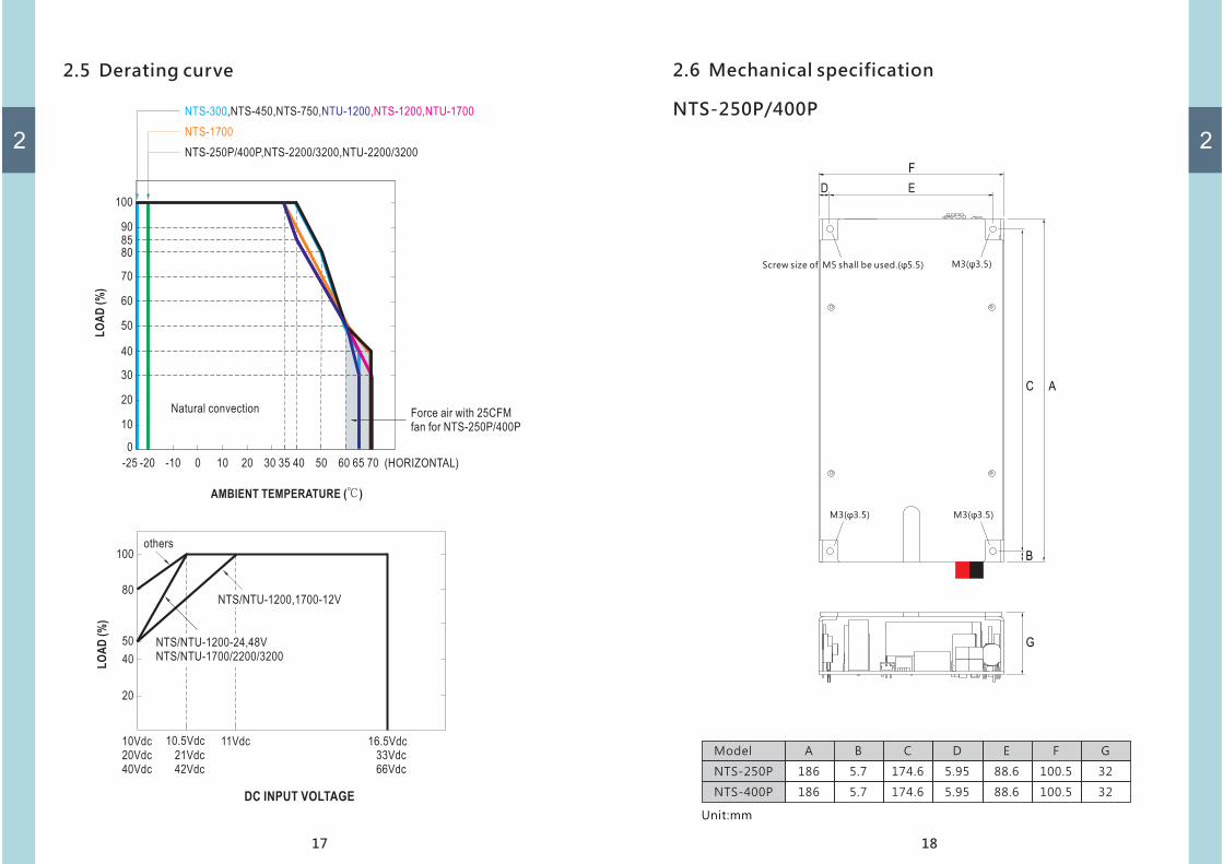
2.5 Derating curve
17
2
LO
AD
(%
)
10Vdc
20Vdc 21Vdc
10.5Vdc
40Vdc 42Vdc
40
20
50
80
100others
11Vdc 16.5Vdc
33Vdc
66Vdc
NTS/NTU-1200,1700-12V
NTS/NTU-1200-24,48V
NTS/NTU-1700/2200/3200
DC INPUT VOLTAGE
LO
AD
(%
)
AMBIENT TEMPERATURE ( )℃
-20 0-10 10 20 30 35 40 50 60 65 70-25 (HORIZONTAL)
NTS-250P/400P,NTS-2200/3200,NTU-2200/3200
NTS-1700
NTS-300,NTS-450,NTS-750,NTU-1200,NTS-1200,NTU-1700
30
20
10
0
40
50
60
70
80
85
90
100
Natural convectionForce air with 25CFM
fan for NTS-250P/400P
2.6 Mechanical specification
NTS-250P/400P
Unit mm:
Model A
186
186
B
5.7
5.7
174.6
174.6
5.95
5.95
88.6
88.6
C D E
100.5
100.5
F G
32
32
NTS-250P
NTS-400P
B
G
C A
ED
F
18
2
Screw size of M5 shall be used.( 5 5)φ . M3( 3 5)φ .
M3( 3 5)φ .M3( 3 5)φ .

Unit mm:
NTS-300/450 750/
Model A
210
270
210
B
45
45
45
C
120
180
120
D
119
147
119
E
130
158
130
F G
7 55
7
7
67
55
NTS-300
NTS-750
NTS-450
NTS-750
NTS-450
F
G
B
AC
D
E
Air flow
direction
19
Reverse Polarity Will
Damage The Unit.
ON
OFF
DC INPUT
+ -Chassis
Bonding
Lug
2
NTS-300
ON
OFF
Reverse Polarity Will Damage The Unit.
DC INPUT
+ -G
Chassis
Bonding
Lug
G
ON
OFF
Reverse Polarity Will Damage The Unit.
DC INPUT
+ -Chassis
Bonding
Lug
Unit mm:
AC
B
D
E
NTS/NTU-1200/1700
DC INPUT
Reverse Polarity Will
Damage The Unit.ON
OFF
G
Model A
333
400
B
56.5
62.5
C
220
275
D
173 184
173 184
E
7
7
F G
70
70
F
20
Air flow
direction
2
NTS/NTU-1200
NTS/NTU-1700
+-
Chassis
Bonding
Lug

Unit mm:
Model A
400
440
B
TBD
TBD
C
TBD
TBD
D
259 270
259 270
E
7.5
7.5
F G
98
98
NTS/NTU-2200
NTS/NTU-3200
NTS/NTU-2200/3200
directiondirection
Air flowAir flow
DC INPUT
Reverse Polarity Will
Damage The Unit.
F
G
AC
B
D
E
21
2
+ -
22
2
MW s Order No.’
Pull Handle
Foot pad
Screw
1
4
2
Item Quantity
1
2
3
Accessories Optional( )
Pull Handle
Foot pad
1
2
M4*2
Carry Handle
RJ11-RS232 1

3
3.2 System Block Diagram
23
3.1 Precautions
Figure 3-1 set up recommendation-
The unit should be mounted on a flat surface or holding rack with
In order to ensure the lifespan of the unit, you should refrain from
NTS-450~3200/NTU-1200~3200 are design with built-in DC fan.
Please make sure the ventilation is not blocked. We recommend
that there should be no barriers within 15cm of the ventilating slits,
AC Input( )for NTU series only
Load>15cm
>15cm
Cable should as short as possible
Inverter
Frame ground FG( )
battery
>15cmInverter
Air flow
>15cm
Air flow
3 Installation & Wiring.
Figure 3-2 System Block Diagram
suitable strength.
operating the unit in environment of high dust or moisture.
which is shown as follow.
Cable should as short as possible
3
Please turn off the inverter first.
Select proper cable for connection between battery and inverter by
referring to section 3.4
Connect the positive polarity of battery to the positive of inverter,
and connect the negative polarity of battery to the negative of
inverter.
Turn the power switch to ON position as soon as it shows green in" " ,
status s LED, then it s ready.’ ’
Wire connections should be as short as possible and less than 1.5
meter is highly recommended. Make sure that suitable wires are
chosen based on safety requirement and rating of current. Small
cross section will result in lower efficiency, less output power and
the wires may also become overheated and cause danger. Please
refer to table 3-1.
3.3 Installation procedures
3.4 Cable selection
Battery+
-
Inverter+
-
Battery+
-
Inverter
+
-
10A ~ 13A 1.25
1.5
2.5
4
6
10
16
25
35
50
16
14
12
10
8
6
4
2
1
0
13A ~ 16A
16A ~ 25A
25A ~ 32A
32A ~ 40A
40A ~ 63A
63A ~ 80A
80A ~ 100A
100A ~ 125A
125A ~ 160A
AWGCorss section(mm )2Rated current(A)
Table 3-1 Cable recommendiation
24
1
2
3
4

3.5 Battery selection
25
Battery types Lead acid or lithium ion batteries:
Voltage range 10 16 5Vdc (12V), 20~33Vdc (24V), 40~66Vdc (48V): ~ .
Battery capacity Please refer to the following table.:
3
Model Output/
NTS-250P
NTS- 075
NTS/NTU-1700
NTS/NTU-2200
Ah85 or above
0Ah25 or above
0Ah50 or above
Ah735 or above
45 or aboveAh
130 or aboveAh
250 or aboveAh
370 or aboveAh
25 or aboveAh
NTS-300 00Ah1 or above 5 or above0Ah 3 or above0Ah
NTS 400P- 0Ah15 or above 7 or above0Ah 35 or aboveAh
NTS- 045 0Ah17 or above 85 or aboveAh 45 or aboveAh
65 or aboveAh
125 or aboveAh
185 or aboveAh
NTS/NTU-3200 Ah1000 or above 500 or aboveAh 250 or aboveAh
NTS/NTU-1200 0Ah40 or above 200 or aboveAh 100 or aboveAh
112 124 148212 224 248
4 User Interface.
4
4.1 AC panelA
B
C
D
E
F
G
NTS-300/450 NTS-750
D A ADC C
E
AC
OU
TP
UT
SWR.C
SW
R.C
Load
Status
Remote port
AC
OU
TP
UT
H
H
H
I
AC output socket : Please refer to Pg. 16 for varies socket for different
regions.
No fuse breaker with reset button (only for NTU-1200/1700/2200/
3200 GFCI series ; NTU 1200 1700 2200 3200 series) :- / / /
Under "bypass mode", when the AC output is shorted or the load
current exceeds the rated current of the No fuse breaker, the breaker
will trip and that stops bypassing energy for the utility thus prevent
possible danger. When the abnormal condition is cleared, the user
can press down on the reset button to resume operation.
Ventilation slits: The inverter requires good ventilation for proper
operation and prolonging its lifetime.
LED indicators : Indicate the status of inverter and the load condition.
Communication port: For remote monitoring purpose, the unit can
be connected to a PC through this communication port by using the
or a cable and monitoring software. Also for remote control purpose,
the unit can be connected to the IRC module through this port.
Power ON/OFF switch : The inverter will turn ON if the switch is in the
ON position, and vice versa.
FG connection
Remote ON/OFF : Inverter will turn on if the pins of RC connector is
open. And, inverter will turn off if the pins are shorted.
AC bypass socket : When AC mains is available, by connecting the AC
mains to the AC socket, it will enable AC bypass function, which the
energy will provide to load from AC mains directly.
26
DC iuputLoad
Status
DC iuput

4
NTS-1700
NTS/NTU-2200/3200
NTU-1700
B
GE
F
C
A
A D
C D
C i r
cu
it
Br
e
ak
er
Pre
ss
to
Re
se t
AC OUTPUT
AC OUTPUT
27
H
I
H
E
NTS-1200 NTU-1200
B CC AA DD
EE
C i r
cu
it
Br
e
ak
er
Pre
ss
to
Re
se t
AC OUTPUTAC OUTPUT
H H
I
C A D
E
AC OUTPUT
H
4
28
4.2 DC input panelA
B
CD
POWER ON/OFF switch: The inverter will turn ON if the switch is inthe ON position, and vice versa.Input terminals (+), (-)Frame ground (FG)Ventilation slits: The inverter requires suitable ventilation to workproperly. Please make sure there is good ventilation and the lifespanof the inverter can preserved.
NTS-750
NTS/NTU-1700
NTS/NTU-1200
NTS/NTU-2200/3200
A
A
A
C
C
C
B
B B
BD
Reverse Polarity Will
Damage The Unit.
ON
OFF
DC INPUT
+ -
DC INPUT
Reverse Polarity Will
Damage The Unit.ON
OFF
DC INPUT
Reverse Polarity Will
Damage The Unit.ON
OFFDC INPUT
Reverse Polarity Will
Damage The Unit.
NTS-300 NTS-450
A AD
C C
B B D
ON
OFF
Reverse Polarity Will Damage The Unit.
DC INPUT
+ -
ON
OFF
Reverse Polarity Will Damage The Unit.
DC INPUT
+ -
+-
+-+-
Chassis
Bonding
Lug
Chassis
Bonding
Lug
Chassis
Bonding
Lug
Chassis
Bonding
Lug
Chassis
Bonding
Lug

4
4.3 LED Indicator
Status indicator :
The LED is used to indicate the status of inverter, including inverter OK,
remote on/off and power saving mode.
Status
Green
Inverter OK
Orange
Remote offAbnormal Status
Saving mode (See below table)
Red
Load
Green
>80% load<40% load 40~80% load
Orange Red
DC Input
Green
12.5~15.5Vdc 11~12.5Vdc <11Vdc or >15.5Vdc
<22Vdc or >31Vdc
<44Vdc or >62Vdc
25~31Vdc 22~25Vdc
50~62Vdc 44~50Vdc
Orange Red
DC Input Indicator:
It is used to show the input status of inverter.
Green light:
When input voltage is greater than 12.5V(12V)/25V(24V) 50V(48V).
Orange light:
When input voltage is within 11V 12.5V(12V)/22V~25V(24V)/44V~50V(48V).~
Red light:
When input voltage is lower than 11V(12V)/22V(24V)/44V(48V) or over it's
specification. It flashes and warning sound will be activated.
Load Condition Indicator:
Itr represents the magnitude of output loads
Green light When load is lesser than 40%.:
Orange light When load is between 40%~80%.:
Red light When load is greater than 80%.:
29
4Green
Light
AC Input Indicator:
Represents the magnitude of AC main.
Green light:
When AC mains is connected and the voltage is present normally.
Flash in green light:
When the mains is connected but the voltage exceeds ±10% of the rated
voltage, the green light will start flashing for warning.
Light off:
when the mains is disconnected or not connected, LED will be in off.
AC InputUtility OK
Light off
Utility error
Flash
Utility disconnect
30

5 Explanation of Operation.
5
31
5.1 Procedure of setting Operating Mode, Output Voltage,
Frequency, and Saving Mode
5.1.3 Remote ON OFF/
Type-US
SW
R.C
Load
DC iuput
Status
Remote port
AC OUTPUT
SW
1 2 3 4
SW1 SW2
OFF OFF : 100Vac or 200Vac
AC Output Voltage Frequency Power Saving Mode、 、 、
OFF ON : 110Vac or 220Vac
ON OFF : 115Vac or 230Vac
ON ON : 120Vac or 240Vac
SW4SW3
ON : 50Hz
OFF: 60Hz
ON : Power saving mode
OFF: Non-power saving mode
Selectable by DIP SW
R.C
5.1.1 Output Voltage and Frequency Setting
Factory settings are either 110Vac/60Hz or 230Vac/50Hz, users are able toadjust the voltage and frequency, through the DIP switch of position1,2,3,4 on the AC panel.
Power Saving Mode setting
When the inverter is in no load status, in order to reduce batteryenergy consumption by inveter accidentally, Position 4 of DIP S.W.on the panel of inverter, can be adjusted to the "ON" position.When this mode is activated, if the load is less than 10W, theinverter will turn off the output and enter the power saving modeafter 3 second. In the power saving mode, the inverter MCU willperiodically detect the output load status. When a load greaterthan 25W is connected, the inverter will switch back to normalmode and start output again. (Non-power saving mode is used asfactory setting)
Open
Short
Normal work
Remote off
R.C Switch
5.1.2
5
32
5.2 Function Difference
NTS-250P/400P NTS-750/1200/1700/2200/3200 NTU-1200/1700/2200/3200
UPS Function
Support RS-232
Support IRC
5.3 IRC1/IRC2/IRC3 Remote Control Unit
� IRC1/IRC2/IRC3 is the monitoring and control unit used for the
inverter series.
� IRC1 IRC2 IRC3 can decode the RS-232 signals sent by the inverter/ /
series and display through digital meters.
Note Part of the control signals will not function properly due to:
different compliance of each model.
NTS-300/450
�
�
�
� �Standard
Funtion model/
MODEL
DIGITAL METER
REMOTE ON/OFF CONTROL
CONTROL OUTPUT
POWER SAVING CONTROL
LED INDICATOR
SUITABLE SERIES
-----
The controlled inverter unit can be turned ON/OFF on the remote control panel for IRC1 / IRC2 / IRC3
Display the battery level, output load level, and operating status of inverter unit
IRC1 IRC2 IRC3
Remote ON/OFF for inverter unit
Power saving enable / disable activation
Remote turn ON(Green) ; Remote turn Off(Orange) ; Abnormal (Red) ; Saving mode (Orange flash)
OUTPUT
FUNCTION
ENVIRONMENT
WORKING TEMP.
WORKING HUMIDITY
VIBRATION
STORAGE TEMP., HUMIDITY
-20 ~ +50℃
20 ~ 90% RH non-condensing
10 ~ 500Hz, 2G 10min./1cycle, 60min. each along X, Y, Z axes
-40 ~ +85 , 10 ~ 95% RH non-condensing℃
EMC EMISSION Compliance to EN55032 class A, EN61000-3-2,3, FCC PART 15 class A
EMC IMMUNITY Compliance to EN61000-4-2,3,4,6,8
186*100.5*32mm (L*W*H)
0.75Kg; 18pcs/ 14.5Kg/ 0.97CUFT
EMC
DIMENSION (L*W*H) (Unit:mm)
PACKINGOTHER
NOTE
1. The remote control can not re-power on for inverter at abnormal status.
2. The ambient temperature derating of 3.5 /1000m with fanless models and of 5 /1000m with fan models for operating altitude higher than℃ ℃
2000m(6500ft).
※ :Product Liability Disclaimer For detailed information, please refer to https://www.meanwell.com/serviceDisclaimer.aspx
TS-700 / 1000 / 1500 / 3000
TN-1500 / 3000
TS-700 / 1000 / 1500 / 3000 TN-1500 / 3000
NTS-750 / 1200 / 1700 / 2200 / 3200NTS-750 / 1200 / 1700 / 2200 / 3200
NTU-1200 / 1700 / 2200 / 3200NTS-750 / 1200 / 1700 / 2200 / 3200
NTU-1200 / 1700 / 2200 / 3200
NTU-1200 / 1700 / 2200 / 3200
�

5
33
Model No : IRC1Inverter Remote Controller
Green
Orange
Red
Orange Flash
ON
OFF
Abnormal
Power Saving
:
:
:
:
PUSH
ON / OFF
Model No : IRC1Inverter Remote Controller
Green
Orange
Red
Orange Flash
ON
OFF
Abnormal
Power Saving
:
:
:
:
PUSH
ON / OFF
Remote port
75
2-R2 (M3)
2.63
55
27
.52
1
69.74
HOLE IN CHASSIS
69.7
2- 4.5ψ
4-R8.2
R1
R4.5
70.5
25
.25
50
.5
Model No : IRC3Inverter Remote Controller
SOLAR CHARGE
Green
Orange
Red
Orange
Flash
ON
OFF
Abnormal
Power
Saving
:
:
:
:
AC
CHARGE
AC IN
BY PASS
INVERTERLOAD
100%
100%
BATTERY
0% 0%
PUSH
ON / OFFModel No : IRC2
Inverter Remote Controller
Green
Orange
Red
Orange
Flash
ON
OFF
Abnormal
Power
Saving
:
:
:
:INVERTER
LOAD100%
100%
BATTERY
0% 0%
PUSH
ON / OFF
5.4 RS-232 Protocol
RS-232 communication can be used between NTS/NTU series products
and external controller (Controller) or PC software. The internal data of
single NTS/NTU can be read through RS-232, but Multiple units in a bus
is not allowed.
The RS-232 of NTS/NTU series are defined as follows.
Control
Baud Rate
Definition of MEAN WELL RS-232 protocol
Command Code Type Command name
Q R Status Inquiry
INVERTER Information
Write Information into INVERTER EEPROM
Remote Control INVERTER
Enable setting mode (for “V”)
Write voltage Frequency、
I R
W W
C W
pU W
V R/W
Data Bits
Stop Bit
Parity
Flow Control
Setting
9600
8
1
None
None
5
34
Definition of command(Q)
49 byte data flowof commandd Q
Databyte
WWW,3
QQQ,3
SSS,4
BBB,3
Funtionname
O/P Voltage
O/P loadpercent(Digital)
O/P loadpercent(Digital)
Batteryvoltage
Batteryvoltage
Batterycapacity
Batterycapacity
Description
O/P Voltage
R/W
R
R
R
R
Range
0~250Vac
0% =0000< ~ ≦30% =02531< ~ ≦50% =05051< ~ ≦75% =07576< ~ % =100
12: 0~17.0Vdc24: 0~34.0Vdc48: 0~68.0Vdc
0 ≦~ <25% =02526<~ ≦50% =05051<~ ≦75% =07576<~ ≦100% =100
Uint
ASCII
ASCII
ASCII
ASCII
Data type
U1
U1
U1
U1
(VVV QQQ SS.S BBB TT.T MMM RR.R DDD PPPb0b1b2b3b4b5b6b7b8b9b10b11b12b13b14b15b16b17b18)
TT.T,4
RR.R,4
DDD,3
b0,1
b1,1
b2,1
PPP,3
MMM,3
Heat Sink Heat Sink
O/P loadPercent(Analog)
O/P loadPercent(Analog)
DC BUSVoltage
DC BUSVoltage
Utility Power Utility Power
Output Power Output Power
Voltage Voltage
Frequency Frequency
Temperature Temperature
INVERTERINVERTERModeMode
BypassMode
BypassMode
UtilityPowersupply
UtilityPowersupply
R
R
R
R
R
R
R
R
0~99 9℃.
40.0~70.0 Hz
0V
1: INVERTER Mode
1: Bypass Mode
1: Utility Power
0~100%
0~250Vac
ASCII
ASCII
ASCII
ASCII
ASCII
ASCII
ASCII
ASCII
U1
U1
U1
U1
U1
U1
U1
U1

35
5
(VVV QQQ SS.S BBB TT.T MMM RR.R DDD PPPb0b1b2b3b4b5b6b7b8b9b10b11b12b13b14b15b16b17b18)
Databyte
Funtionname
Description R/W Range UintData type
b3,1
b4,1
UtilityChargerEnable
UtilityChargerEnable
SolarChargerEnable
SolarChargerEnable
R
R
1: Enable
1: Enable
ASCII
ASCII
U1
U1
b5,1
b6,1
b8,1
b10,1
b11,1
b12,1
b13,1
b14,1
b15,1
b9,1
b7,1
SavingMode
SavingMode
BatteryBattery
BatteryOVP
BatteryOVP
OLPOLP
OLPOLP
OLP150% ~
OLP150% ~
OTPOTP
INV UVPINV UVP
INV OVPINV OVP
100 ~ 115 %100 ~ 115 %
115 ~ 150 %115 ~ 150 %
RemoteRemoteShutdownShutdown
ShutdownShutdown
ModeMode
OccurredOccurred
ExhaustedExhausted
R
R
R
R
R
R
R
R
R
R
R
1: Saving Mode
1: Battery low
1: Battery OVP
1: Inverter OTP2: Fan lock protection
1: INV UVP
1: INV UVP
1: Occurred OLP 100 ~%
1: Occurred OLP 115%~
1: Occurred OLP 150%~
1: Remote Shutdown
ASCII
ASCII
ASCII
ASCII
ASCII
ASCII
ASCII
ASCII
ASCII
ASCII
ASCII
U1
U1
U1
U1
U1
U1
U1
U1
U1
U1
U1Mode(Batteryused up)
Mode(Batteryused up)
49 byte data flowof commandd Q
Shutdown Mode
(Battery used up)
36
5
Definition of command(I、W)
Databyte
Funtionname
Description R/W Range UintData type
Databyte
Funtionname
Description R/W Range UintData type
b18,1
b16,1
b17,1
SystemSystemShutdownShutdown
INV FaultINV Fault
EEPROMerrorcode
EEPROMerrorcode
R
R
R
1: Shutdown
1: INV Fault
1: EEPROM error
ASCII
ASCII
ASCII
U1
U1
U1
1
1
4
4
Voltage &Freq. setting
Voltage &Freq. setting
ModelCode
ModelCode
Equalization EqualizationVolt. Volt.
FloatingVolt.
FloatingVolt.
R
R
W/R
W/R
100V(200V)/50Hz=00
110V(220V)/50Hz=01115V(230V)/50Hz=02120V(240V)/50Hz=03100V(200V)/60Hz=04110V(220V)/60Hz=05115V(230V)/60Hz=06120V(240V)/60Hz=07(Defermind by DIP SW)
112=00124=01148=02212=03224=04248=05(Defermind by DIP SW)
12: 9.0~15.0Vdc24: 18.0~30.0Vdc48: 36.0~60.0Vdc( nsuported)U
12: 9.0~15.0Vdc24: 18.0~30.0Vdc48: 36.0~60.0Vdc( nsuported)U
Binary
Binary
ASCII
ASCII
Binary
U1
U1
U1
U1
1 Saving mode Saving mode RDisable=00Enable=01(Defermind by DIP SW)
U1

37
5
4
4
AlarmVolt.
AlarmVolt.
ShutdownVolt.
ShutdownVolt.
W/R
W/R
12: 9.0~15.0Vdc24: 18.0~30.0Vdc48: 36.0~60.0VdcNote 1 2、
12: 9.0~15.0Vdc24: 18.0~30.0Vdc48: 36.0~60.0VdcNote 1 2、
ASCII
ASCII
U1
U1
ASCII
ASCII
ASCII
ASCII
ASCII
ASCII
ASCII
10
19
1
1
1
ManufactureCountry
ManufactureCountry
SerialNumber
SerialNumber
ModelName
ModelName
Date Date
Checksum Checksum
W/R
W/R
W/R
W/R
MEANWELL
LOC-xxxxxxxxxxxxxxxx(x: 0~9 )
Define by each model(max of 14 digits)
Date :MM/DD/YYYY
U1
U1
U1
U1
U1
9
1
Revision Revision
BatteryFirstFlag
BatteryFirstFlag
R
W/R
REV:vv v.(Define by FW,
ot changeable)n
0 = Disable1= Enable
U1
U1
4TransferVolt.
TransferVolt.
W/R
12: 9.0~15.0Vdc24: 18.0~30.0Vdc48: 36.0~60.0Vdc( nsuported))U
ASCIIU1
4FloatingVolt.
FloatingVolt.
W/R
12: 9.0~15.0Vdc24: 18.0~30.0Vdc48: 36.0~60.0Vdc( nsuported))U
ASCIIU1
Databyte
Funtionname
Description R/W Range UintData type
38
5
ASCII
ASCII
ASCII
ASCII
ASCII
ASCII
ASCII
Shutdown
Shutdown
Turn onTurn onINVERTERINVERTER
Preserved
Preserved
Preserved
Preserved
Preserved
Preserved
Preserved
Preserved
Preserved
Preserved
Preserved
Preserved
Preserved
Preserved
Preserved
Preserved
Preserved
Preserved
Preserved
Preserved
Preserved
Preserved
Preserved
Preserved
Preserved
Preserved
W
W
1: Remote Shutdown
1: Remote On INV
Fixed”0x30”
Fixed”0x30”
Fixed”0x30”
Fixed”0x30”
Fixed”0x30”
Fixed”0x30”
Fixed”0x30”
Fixed”0x30”
Fixed”0x30”
Fixed”0x30”
Fixed”0x30”
Fixed”0x30”
Fixed”0x30”
U1
U1
U1
U1
U1
U1
U1
Definition of command C( )
ASCII
ASCII
ASCII
ASCII
ASCII
ASCII
ASCII
U1
U1
U1
U1
U1
U1
U1
ASCIIU1
ASCII
ASCII
3
3
2
Frequencysetting
Frequencysetting
Checksum Checksum
W/R
W/R
110 Series
220 Series
000 disable:(Voltage is define by DIP SW.)
:100~127 100~127Vac
:200~240 200~240Vac
050 50Hz:060 60Hz:000 disable:
U1
U1
Voltagesetting
To set anyAC Voltagewithin therange
Definition of command(V)
Databyte
Funtionname
Description R/W Range UintData type
Databyte
Funtionname
Description R/W Range UintData type
b0,1
b1,1
b2,1
b3,1
b4,1
b5,1
b6,1
b8,1
b9,1
b10,1
b11,1
b12,1
b13,1
b14,1
b7,1

39
5
Note:1 Voltage setting of battery must fufill follwing condictions、
15.0 V> Equalization_Volt.> Floating_Volt.
>Alarm_Volt.>Shutdown_Volt. >09.0V。, . . 'Inorder to comply the requirement use max of 15 0V for setting when it s not
supported.
2 If Alarm_Volt ≦ Shutdown_Volt. then the command is not valid、 , .
5.5 Mode only for NTU seriesUPS ( )
5.5.1 Explanation of UPS mode
ON
Vfloat
ON
OFF
ONON
By pass
mode
Inverter
Mode
Input
voltage
OFF
OFF
OFF
ON
Power-On Re-power-on
(Shut-down)
t
t
t
Utility
Power
ON
OFF
Bat low
ON
OFF
OFF
OFF
Von
T1 T2 T3 T4 T5
Vboost
After the user turns on the NTU-1200/1700/2200/3200, if it detectsthat the mains voltage is normal, the NTU will enter the bypass mode,so the load will be supplied by the mains directly. While battery is in afully charged status.
If the AC mains fails or when the voltage of AC mains exceeds 16% of±
the setting, the NTU will immediately switch to inverter mode, toensure customer's equipment will not be affected. Take NTU-1200-124(default 110Vac) as an example, when the voltage of AC mains isgreater then 127.6Vac or less than 92.4Vac, NTU-1200-124 will enterthe inverter mode to keep equipment running, and the energy isconsumed from the battery.
T1 :
T2 :
or
battery
voltage
��
5
When NTU works in bypass mode, the charger can maintain the
battery voltage and provide enough power when the AC mains is
abnormal. If the AC mains returns from abnormally, the charger can
also provide the power that lost when operating in inverter mode. For
connection, please select wires or cable with a suitable wire diameter
according to the output current when connect the battery and
inverter. Please refer to table 3-1 for connection.
5.5.2 UPS System Block Diagram
Charger
If the AC mains has returned to a range within +/-13% of the NTU's set
value, the NTU will switch to bypass mode again and supply power
from the mains to the load. In the meantime, the battery can be
charged through an external charger.
When the voltage of battery pack is consumed to the lower limit of the
inverter s operating range, and the AC main still not valid. At this time,’
the battery charger cannot provide energy any more, so the inverter
will keep operate until the battery voltage has consumed till the lower
limit of the inverter's operating voltage. Eventually, inverter will
shutdown.
When the voltage of battery returned to operating range inverter will,
restart automatically.
T3 :
T4 :
T5 :
Frame ground FG( )
(Suggest to work accompany with MEAN WELL NPB/NPP chargers)
Battery
Inverter
AC Input( )for NTU series only
>15cmLoad
>15cm
>15cm
Cable should as short as possible

6 Protections and Failure Correction.
6
6.2 Failure Correction
AC Output Over Load Protection :
When overloaded, the inverter is able to supply power for a period of time.
If the load does not drop back to the normal range,the OLP will be triggered
and turn off the inverter. Once the OLP condition is removed, re-power on the
inverter to start operation again.
AC Output Short Circuit Protection :
When short-circuit occurs or the load increasing significantly, the inverter will
turn off for protection. After removing the fault condition, re-power on the
inverter to start operation.
6.1 Protection Funtion:
Inverter Protection :Over temperature protection(OTP) :
When the temperature inside the inverter raise to a certain level, the inverter willturn off for protection. After the temperate dropped back to operating range, re-power the inverter for operation.
Once failure condition occurs, the LED on panel of inverter will show different LED
light for indication. Fault condition can be separated into 4 categories, AC output
protection, DC input protection, over temperature protection or other. Please
refer to the following table for fault indication and correction. If the faultcondition cannot be solved, please contact MEAN WELL's distributor
for further assistance.
41
DC Input Protection :
AC Output Protection :
DC Polarity Protection :
When connecting the DC polarity reversely, the internal fuse will blow for
protection. The unit then must return to MEAN WELL's distributor for further
support.
Low DC Input Protection :
When DC input is lower than the operating range, inverter will turn off
automatically for protection.
Over Voltage of DC Input :
When the voltage of DC input over the operating range, the inverter will turn
off for protection. After the fault condition is removed, inverter will restart
automatically. If the inverter cannot operate normally after wards, it
represents that the inverter is damaged. Please return the unit to MEAN
WELL's distributor if needed.
6
fault signal
Status
Status
Status
Status
DC Input
DC Input
DC Input
Load
Load
Load
DC Input
Load
Possible cause Suggestions for Fault correction
Short circuit protection
Check if the load requirement
Over load protection
Check if the load requires high
star tup current, such as inductive
Aged battery or malfunction Change a new battery
Wrong battery capacitanceRe check if the parameter of battery
suits inverter's operating parameter
Other fault condition that's
not defined
Contact MEAN WELL's
distributor
Over temperature protection
Remove subject away from venthole
if any. If it's due to high ambient,
please lower the temperate or load
42
Note: Light
Light off
Flash
to proceed. After the fault condition
or capacitance loads. After the
fault condition is remover, re-
power the inverter for operation.
exceed the rated value or if the
circuit is shorted.
is remove, re-power inverter for
operation.

43
7 Warranty.This product provide three years warranty under normal usage. Do not replace
parts or any form of modification to the product in order to keep the warranty
effectively.
※ MEAN WELL posses the right to adjust the content of
this manual. Please refer to the latest version of our
manual on our website. https://www.meanwell.com MEAN WELL WEB Inverter Manual
6
7

No.28 , Wuquan 3rd Rd. , Wugu D is t . , New Ta ipe i C i ty 248 , Ta iwan