ntcip 1205 object definitions for closed circuit … definitions for closed circuit television...
TRANSCRIPT
A Recommended Standard of the Joint Committee on the NTCIP
NTCIP 1205 v01.07
National Transportation Communications for ITS Protocol (NTCIP)
Object Definitions for Closed Circuit Television (CCTV) Camera Control
July 12, 1999
This is a draft document, which is distributed for review and ballot purposes only. You may reproduce and distribute this document within your organization, but only for the purposes of and only to the extent necessary to facilitate review and ballot to AASHTO, ITE, or NEMA. Please ensure that all copies reproduced or distributed bear this legend. This document contains recommended information which is subject to approval.
Published by American Association of State Highway and Transportation Officials (AASHTO) 444 North Capitol St., N.W., Suite 249 Washington, DC, 20001 Institute of Transportation Engineers (ITE) 525 School St., S.W., Suite 410 Washington, DC, 20024-2797 National Electrical Manufacturers Association (NEMA) 1300 N. 17th Street, Suite 1847 Rosslyn, Virginia 22209-3801

NTCIP 1205, v01.07 Joint AASHTO/ITE/NEMA Committee on the NTCIP Page ii July 12, 1999
CCTV WG Recommended Standard ? 2000 AASHTO / ITE / NEMA
? Copyright 2000 AASHTO/ ITE / NEMA. All rights reserved.

Joint AASHTO/ITE/NEMA Committee on the NTCIP NTCIP 1205, v01.07 July 12, 1999 Page iii
CCTV WG Recommended Standard ? 2000 AASHTO / ITE / NEMA
ACKNOWLEDGEMENTS
This publication was prepared by the NTCIP CCTV Working Group, a subdivision of the Joint Committee on the NTCIP. The Joint Committee is organized under a cooperative agreement among the American Association of State Highway and Transportation Officials (AASHTO), the Institute of Transportation Engineers (ITE), and the National Electrical Manufacturers Association (NEMA). The NTCIP development effort is guided by the NTCIP Joint Committee, which consists of six representatives from each of the above organizations. At the time that this document was prepared, the following individuals were members of the NTCIP CCTV Working Group:
? ? Joseph Bowman ? ? Mike Forbis (chair) ? ? G. Curtis Herrick ? ? John McDonough ? ? Emmanual Morala ? ? Bruce Pluth ? ? Stephen L. Robinson ? ? Canny Quach ? ? Shahram Shahriari ? ? Phillip Tran ? ? Keith Vennel
In addition to the many volunteer efforts, recognition is also given to those organizations that supported the efforts of the NTCIP CCTV Working Group by providing comments and resources for the development of the standard, including:
? ? California Department of Transportation ? ? Cohu, Inc. ? ? Diamond Electronics, Inc. ? ? Federal Highway Administration ? ? Gardner Transportation Systems, Inc. ? ? Gyyr, Inc ? ? Image Sensing Systems, Inc. ? ? Los Angeles Department of Transportation ? ? Ontario Ministry of Transportation ? ? Pelco, Inc. ? ? Sensormatic Electronics Corporation ? ? Washington State Department of Transportation
NTCIP 1205, v01.07 Joint AASHTO/ITE/NEMA Committee on the NTCIP Page iv July 12, 1999
CCTV WG Recommended Standard ? 2000 AASHTO / ITE / NEMA
FOREWORD
This document defines the Closed Circuit Television (CCTV) data elements, or objects, that are supported by the National Transportation Communications for ITS Protocol (NTCIP). The effort to develop NTCIP began with the 3-TS Transportation Management Systems and Associated Control Devices Section of the National Electrical Manufacturer's Association (NEMA). Their original desire was to address a user need for extending the TS-2 Standards for traffic control hardware to include standardized systems communication. Under the guidance of the Federal Highway Administration’s (FHWA) NTCIP Steering Group, the NEMA effort was expanded to include the development of communications standards for all transportation field devices that could be used in Intelligent Transportation Systems (ITS) networks. In September 1996, a formal agreement was reached among NEMA, the Institute of Transportation Engineers (ITE) and the American Association of State Highway and Transportation Officials (AASHTO) to jointly develop, approve and maintain the NTCIP standards. Under the guidance of a Joint AASHTO/ITE/NEMA Committee on the NTCIP, a Working Group was created in order to develop the object definitions Closed Circuit Televisions. The first official meeting of this working group was in August 1997. The NTCIP Object Definitions for Closed Circuit Television (CCTV) Camera Control defines objects in ASN.1 using the SNMP Object Type Macro for devices that sense the presence or similar characteristics of vehicles. These definitions are intended for CCTV camera control devices. For more information about NTCIP standards, visit the NTCIP Web Site at http://www.ntcip.org. For a hardcopy summary of NTCIP information, contact the NTCIP Coordinator at the following address.
NTCIP Coordinator National Electrical Manufacturers Association 1300 N.17th Street, Suite 1847 Rosslyn, Virginia 22209-3801 fax: (703) 841-3331 e-mail: [email protected]
History This standard [was separately balloted and approved by AASHTO, ITE, and NEMA after formal recommendation by the Joint Committee on the NTCIP. Text to be added.]

Joint AASHTO/ITE/NEMA Committee on the NTCIP NTCIP 1205, v01.07 July 12, 1999 Page v
CCTV WG Recommended Standard ? 2000 AASHTO / ITE / NEMA
INTRODUCTION
The purpose of this document is to define the Closed Circuit Television (CCTV) Camera Control objects that are supported by the NTCIP. The following keywords apply to this document: AASHTO, ITE, NEMA, NTCIP, CCTV, camera control, objects. The effort to develop NTCIP began in 1992 with the 3-TS Transportation Management Systems and Associated Control Devices Section of NEMA. Their original desire was to address a user need for extending the TS 2 Standards for traffic control hardware to include standardized systems communication. Under the guidance of the Federal Highway Administration’s (FHWA) NTCIP Steering Group, the NEMA effort was expanded to include the development of communications standards for all transportation field devices that could be used in an Intelligent Transportation Systems (ITS) network. In September 1996, a formal agreement was reached among NEMA, the Institute of Transportation Engineers (ITE) and the American Association of State Highway and Transportation Officials (AASHTO) to jointly develop, approve and maintain the NTCIP standards. Under the guidance of a Joint AASHTO/ITE/NEMA Committee on the NTCIP, a Working Group was created in order to develop the object definitions Closed Circuit Televisions. The first official meeting of this working group was in August 1997.
NTCIP 1205, v01.07 Joint AASHTO/ITE/NEMA Committee on the NTCIP Page vi July 12, 1999
CCTV WG Recommended Standard ? 2000 AASHTO / ITE / NEMA
If you are not willing to abide by the following copyright statement, return these materials immediately. ? Copyright 2000 by the American Association of State Highway and Transportation Officials (AASHTO), the Institute of Transportation Engineers (ITE), and the National Electrical Manufacturers Association (NEMA). All intellectual property rights, including, but not limited to, the rights of reproduction in whole or in part in any form, translation into other languages and display are reserved by the copyright owners under the laws of the United States of America, the Universal Copyright Convention, the Berne Convention, and the International and Pan American Copyright Conventions. Except for the MIB, do not copy without written permission of either AASHTO, ITE, or NEMA.
Joint AASHTO, ITE, and NEMA NTCIP Management Information Base
DISTRIBUTION NOTICE
To the extent and in the limited event these materials are distributed by AASHTO/ITE/NEMA in the form of a Management Information Base ("MIB"), AASHTO/ITE/NEMA extends the following permissions:
(i) you may make and/or distribute unlimited copies (including derivative works) of the MIB, including copies for commercial distribution, provided that (a) each copy you make and/or distribute contains this Notice and (b) each derivative work of the MIB used the same module name followed by "-" followed by your Internet Assigned Number Authority (IANA)-assigned enterprise number. (ii) use of the MIB is restricted in that the syntax field may be modified only to reflect a more restrictive subrange or enumerated values; (iii) the description field may be modified but only to the extent that: (a) only those bit values or enumerated values that are supported are listed; and (b) the more restrictive subrange is expressed.
These materials are delivered "AS IS" without any warranties as to their use or performance. AASHTO/ITE/NEMA AND THEIR SUPPLIERS DO NOT WARRANT THE PERFORMANCE OR RESULTS YOU MAY OBTAIN BY USING THESE MATERIALS. AASHTO/ITE/NEMA AND THEIR SUPPLIERS MAKE NO WARRANTIES, EXPRESSED OR IMPLIED, AS TO NON-INFRINGEMENT OF THIRD PARTY RIGHTS, MERCHANTABILITY, OR FITNESS FOR ANY PARTICULAR PURPOSE. IN NO EVENT WILL AASHTO, ITE, OR NEMA OR THEIR SUPPLIERS BE LIABLE TO YOU OR ANY THIRD PART FOR ANY CLAIM OR FOR ANY CONSEQUENTIAL, INCIDENTAL, OR SPECIAL DAMAGES, INCLUDING ANY LOST PROFITS OR LOST SAVINGS, ARISING FROM YOUR REPRODUCTION OR USE OF THESE MATERIALS. EVEN IF AN AASHTO, ITE, OR NEMA REPRESENTATIVE HAS BEEN ADVISED OF THE POSSIBILITY OF SUCH DAMAGES. Some states or jurisdictions do not allow the exclusion or limitation of incidental, consequential, or special damages, or exclusion of implied warranties, so the above limitations may not apply to you. Use of these materials do not constitute an endorsement or affiliation by or between AASHTO, ITE, or NEMA and you, your company, or your products and services. If you are not willing to accept the foregoing restrictions, you should immediately return these materials. NTCIP is a trademark of AASHTO/ITE/NEMA.
Joint AASHTO/ITE/NEMA Committee on the NTCIP NTCIP 1205, v01.07 July 12, 1999 Page vii
CCTV WG Recommended Standard ? 2000 AASHTO / ITE / NEMA
CONTENTS
Acknowledgements................................................................................................................................. iii
Foreword ............................................................................................................................................ iv
Introduction ............................................................................................................................................. v
Contents ........................................................................................................................................... vii
Section 1 CCTV OVERVIEW................................................................................................................1-1 1.1 Introduction TO CCTV .......................................................................................................1-1 1.2 Benefits of standardization.................................................................................................1-1 1.3 Existing Standards.............................................................................................................1-2
1.3.1 Internet Standards.................................................................................................1-3 1.3.2 International Organization of Standardization Standards .......................................1-3 1.3.3 NTCIP...................................................................................................................1-3 1.3.4 NTCIP System Design...........................................................................................1-3
1.4 Closed Circuit Television ...................................................................................................1-4 1.4.1 Discussion of CCTV Coordinate Systems..............................................................1-4 1.4.2 Discussion of Limit Stops in CCTV Systems..........................................................1-6
Section 2 GENERAL ............................................................................................................................2-1 2.1 Scope ................................................................................................................................2-1 2.2 References ........................................................................................................................2-1
2.2.1 Normative References...........................................................................................2-1 2.2.2 Other References..................................................................................................2-2 2.2.3 Contact Information...............................................................................................2-2
2.3 Terms ................................................................................................................................2-2 2.4 Acronyms ..........................................................................................................................2-4 2.5 Supplemental figures .........................................................................................................2-5
Section 3 CCTV MIB ............................................................................................................................3-1 3.1 Closed Circuit Television (CCTV) Objects..........................................................................3-1 3.2 CCTV Range Objects ........................................................................................................3-2
3.2.1 Maximum Number of Presets Parameter...............................................................3-2 3.2.2 Pan Left Limit Parameter ......................................................................................3-2 3.2.3 Pan Right Limit Parameter ....................................................................................3-2 3.2.4 Pan Home Position Parameter ..............................................................................3-2 3.2.5 True North Offset Parameter .................................................................................3-2 3.2.6 Tilt Up Limit Parameter .........................................................................................3-3 3.2.7 Tilt Down Limit Parameter .....................................................................................3-3 3.2.8 Zoom Limit Parameter...........................................................................................3-3 3.2.9 Focus Limit Parameter ..........................................................................................3-3 3.2.10 Iris Limit Parameter...............................................................................................3-4 3.2.11 Maximum Pan Step Angle Parameter ...................................................................3-4 3.2.12 Maximum Tilt Step Angle Parameter.....................................................................3-4
3.3 CCTV Timeout Objects......................................................................................................3-4 3.3.1 Pan Timeout Parameter ........................................................................................3-4 3.3.2 Tile Timeout Parameter.........................................................................................3-5 3.3.3 Zoom Timeout Parameter .....................................................................................3-5 3.3.4 Focus Timeout Parameter .....................................................................................3-5 3.3.5 Iris Timeout Parameter..........................................................................................3-5
3.4 CCTV Preset Objects.........................................................................................................3-5
NTCIP 1205, v01.07 Joint AASHTO/ITE/NEMA Committee on the NTCIP Page viii July 12, 1999
CCTV WG Recommended Standard ? 2000 AASHTO / ITE / NEMA
3.4.1 Go To Preset Position Parameter ..........................................................................3-5 3.4.2 Store Preset Position Parameter ...........................................................................3-6
3.5 CCTV Positioning Objects..................................................................................................3-6 3.5.1 Pan Position Parameter.........................................................................................3-6 3.5.2 Tilt Position Parameter..........................................................................................3-6 3.5.3 Lens Zoom Position Parameter .............................................................................3-6 3.5.4 Lens Focus Position Parameter.............................................................................3-7 3.5.5 Lens Iris Position Parameter..................................................................................3-7
3.6 CCTV System Feature Control Objects..............................................................................3-7 3.6.1 System Camera Feature Control Parameter..........................................................3-7 3.6.2 System Camera Feature Status.............................................................................3-8 3.6.3 System Camera Equipment Availability Parameter ...............................................3-8 3.6.4 System Lens Feature Control Parameter...............................................................3-8 3.6.5 System Lens Feature Status Parameter ................................................................3-9 3.6.6 System Lens Equipment Availability Parameter ....................................................3-9
3.7 CCTV Alarm Objects .........................................................................................................3-9 3.7.1 Alarm Status Parameter ........................................................................................3-9 3.7.2 Alarm Latch Status Parameter.............................................................................3-10 3.7.3 Alarm Latch Clear Parameter ..............................................................................3-10 3.7.4 Temperature Alarm High-Low Threshold .............................................................3-10 3.7.5 Temperature Alarm Current Value Parameter .....................................................3-11 3.7.6 Pressure Alarm High-Low Threshold Parameter ..................................................3-11 3.7.7 Pressure Alarm Current Value Parameter............................................................3-11 3.7.8 Washer Fluid Alarm High-Low Threshold Parameter ...........................................3-11 3.7.9 Washer Fluid Alarm Current Value Parameter.....................................................3-11 3.7.10 Alarm Label Index Parameter..............................................................................3-12
3.8 CCTV Discrete Input Objects ...........................................................................................3-12 3.8.1 Discrete Input Status Parameter..........................................................................3-12 3.8.2 Discrete Input Latch Status Parameter ................................................................3-12 3.8.3 Discrete Input Latch Clear Parameter..................................................................3-13 3.8.4 Discrete Input Label Index Parameter..................................................................3-13
3.9 CCTV Discrete Output Objects ........................................................................................3-13 3.9.1 Discrete Output Status Parameter .......................................................................3-14 3.9.2 Discrete Output Control Parameter......................................................................3-14 3.9.3 Discrete Output Label Index ................................................................................3-14
3.10 CCTV Zone Objects.........................................................................................................3-15 3.10.1 Maximum Number of Zones Parameter...............................................................3-15 3.10.2 Zone Table..........................................................................................................3-15
3.11 CCTV Label Objects ........................................................................................................3-16 3.11.1 Maximum Number of Labels Parameter ..............................................................3-17 3.11.2 Label Table .........................................................................................................3-17 3.11.3 Label Location Parameter ...................................................................................3-20 3.11.4 Enable Label Text Display...................................................................................3-20
3.12 CCTV On-Screen Camera Menu Objects.........................................................................3-20 3.12.1 Activate Menu Parameter....................................................................................3-20 3.12.2 Menu Control Parameter .....................................................................................3-20
Section 4 CONFORMANCE .................................................................................................................4-1 4.1 Conformance Groups.........................................................................................................4-1
4.1.1 CCTV Configuration Conformance Group .............................................................4-2 4.1.2 Extended Functions Conformance Group..............................................................4-2 4.1.3 Motion Control Conformance Group ......................................................................4-3 4.1.4 On-Screen Menu Control Conformance Group ......................................................4-4
4.2 Conformance Statements ..................................................................................................4-4

Joint AASHTO/ITE/NEMA Committee on the NTCIP NTCIP 1205, v01.07 July 12, 1999 Page ix
CCTV WG Recommended Standard ? 2000 AASHTO / ITE / NEMA
Informative Annex A EXTENDED GLOSSARY................................................................ A-1


Joint AASHTO/ITE/NEMA Committee on the NTCIP NTCIP 1205, v01.07 July 12, 1999 Page 1-1
CCTV WG Recommended Standard ? 2000 AASHTO / ITE / NEMA
Section 1 CCTV OVERVIEW
1.1 INTRODUCTION TO CCTV
The context of the NTCIP is one part of the Intelligent Transportation Systems (ITS) standardization activities covering base standards, profiles, and registration mechanisms.
? ? Base Standards define procedures and rules for providing the fundamental operations associated with communications and information that is exchanged over fixed-point communications links.
? ? Profiles define subsets or combinations of base standards used to provide specific functions or
services. Profiles prescribe particular subsets or options available in base standards necessary for accomplishing a particular function or service. This provides a basis for the development of uniform, nationally recognized conformance.
? ? Registration Mechanisms provide a means to specify and uniquely identify detailed parameters
within the framework of base standards and/or profiles. Within the Joint AASHTO/ITE/NEMA NTCIP Committee, other working groups are concerned with the methodology of defining profiles, and their documentation in Standards Publications. The objective is to facilitate the specification of ITS systems characterized by a high degree of interoperability and interchangeability of its components. This document covers the control and status requirements of cameras, lenses, pan/tilt units. Video switches are an integral part of many CCTV systems, however, NTCIP standards for controlling video switches will be issued as a separate and distinct standards document. A CCTV Camera Control subsystem is comprised of an assembly of camera, lens, and pan/tilt functions. Unfortunately, there are no existing standards that define how these devices communicate with other related equipment. As a result, each manufacturer has developed its own protocol to meet their particular needs. To integrate systems manufactured by different companies, considerable extra work must be performed resulting in increased costs. This shortcoming limits interchangeability of components between different vendors and restricts the sharing of information and control within and between user organizations. These problems have not been limited to CCTV surveillance systems. Many other devices also need to share network infrastructure and exchange information. In surface transportation, examples include traffic signal controllers, dynamic message signs, bus priority sensors, etc. To address these problems, the NTCIP is developing a family of open standards for communications among field devices and between field devices and central management stations, known as Traffic Management Subsystems (TMS). The NTCIP CCTV standard describes objects that control the camera subsystem. As previously mentioned, objects that control video switches will be issued under separate cover. 1.2 BENEFITS OF STANDARDIZATION
As transportation systems become more sophisticated, planners, users, and equipment manufacturers recognize the need for system interoperability and integration. Currently, there is no common protocol with which different types of equipment can communicate. If CCTV is to be integrated with ITS, common
NTCIP 1205, v01.07 Joint AASHTO/ITE/NEMA Committee on the NTCIP Page 1-2 July 12, 1999
CCTV WG Recommended Standard ? 2000 AASHTO / ITE / NEMA
communications standards must be established. Before the NTCIP development started, each vendor of electronic devices used in transportation adopted a different protocol for data communications. This made it very difficult to mix equipment from different vendors in the same system, and to communicate between systems operated by adjacent agencies. The NTCIP is now providing a common standard that can be used by all vendors. The NTCIP offers increased flexibility and choice for agencies operating traffic management systems. It removes barriers to inter-jurisdictional coordination and allows equipment of different types and manufacturers to be mixed on the same communications line. For these reasons, operating agencies will benefit from specifying that the NTCIP is included in all future purchases and upgrades. Benefits of adopting open standards based on the NTCIP include:
? ? Avoiding Early Obsolescence: Though it may not be practical to retrofit NTCIP support in some old equipment, most CCTV vendors will offer NTCIP support in current and future products. An operating agency can ensure that its equipment remains useful and compatible long into the future by requiring NTCIP support for all future purchases and upgrades. This will include central computers and CCTV field devices, such as cameras, pan/tilt mechanisms, lens, and video switchers.
? ? Providing Choice of Vendor: Once an agency has a CCTV surveillance system that includes support for NTCIP it can buy field devices from any manufacturer offering NTCIP-compatible products, and they will communicate with the agency’s “Traffic Management Subsystem” (‘TMS’, typically termed CPU).
? ? Allowing Interjurisdictional Coordination: In the future, an agency may want to communicate with CCTV devices owned by other users and/or procured from different vendors. Under NTCIP, these various devices can be added onto an existing communications channel and mixed with different types of devices on the same line.
? ? Using one Communications Network for All Devices: NTCIP also allows a central computer to communicate with a range of field devices on the same communications channel. For example, if a dynamic message sign is installed near a CCTV camera control receiver, the central computer could communicate with the sign controller using the communications channel already in place for the CCTV camera control receiver. The communications network is usually the most expensive component of a transportation management system and use of the NTCIP maximizes that investment.
Several state and local transportation agencies already have a number of CCTV surveillance systems deployed for traffic and transportation management. At present, however, these systems often include proprietary elements that limit expansion and upgrade opportunities. The development of the NTCIP will allow a more open-systems approach, not only among CCTV equipment, but also with a wide variety of other field devices. It is expected that this open-systems approach will result in lower deployment and equipment costs similar to the PC industry. This in turn will allow for more devices to be deployed resulting in better decision-support to decrease maintenance costs. To make best use of these advancements, CCTV should be viewed in the much broader context of Intelligent Transportation Systems (ITS). The key to these benefits is open standards, allowing agencies to share data and avoid becoming locked into proprietary systems. 1.3 EXISTING STANDARDS
There are great benefits of adopting existing standards where possible. These include: ? ? reuse of software modules during development ? ? faster implementations
Joint AASHTO/ITE/NEMA Committee on the NTCIP NTCIP 1205, v01.07 July 12, 1999 Page 1-3
CCTV WG Recommended Standard ? 2000 AASHTO / ITE / NEMA
? ? reducing risks ? ? ability to integrate components from different manufacturers ? ? unambiguous meanings of terminology ? ? building on proven technologies
1.3.1 Internet Standards The Internet Engineering Task Force (IETF) is responsible for developing and maintaining the standards, guidelines and procedures for communications over the Internet. This group has become increasingly important over the last few years as the Internet has gained popularity. A wide range of Internet standards exist, including:
? ? Point-to-Point Protocol (PPP) - which may be used for NTCIP dial-up links ? ? Internet Protocol (IP) - which may be used for NTCIP communications over networks ? ? Transport Control Protocol (TCP) - which may be used to provide connection-oriented transport
services over NTCIP networks ? ? User Datagram Protocol (UDP) - which may be used to provide connectionless transport services
over NTCIP networks ? ? Simple Network Management Protocol (SNMP) - which may be used to exchange NTCIP data
elements such as those defined within this document. 1.3.2 International Organization of Standardization Standards The International Organization of Standardization (ISO) also develops various communication standards among a wide variety of other standards. The Open Systems Interconnect Reference Model (OSI) is a widely-referenced ISO standard which defines the standard seven-layered communications model. While most implementations do not strictly conform to this standard, virtually all modern communications schemes, including the NTCIP, use many of the concepts defined within the standard. In addition, NTCIP communications may use the High Level Data Link Control Protocol (HDLC), another ISO standard, in specifying how to send a message over a single communications link. 1.3.3 NTCIP To support ITS developments, US DOT funded the design of a National ITS Architecture. This architecture defines major ITS subsystems and the needs for information exchange among them. The National Transportation Communications for ITS Protocol (NTCIP) group is now developing standards for these information exchanges. NTCIP – a joint initiative of AASHTO, ITE, and NEMA – recognizes that closed circuit television is a vital component of traffic and transportation management systems. The family of NTCIP standards will enhance CCTV implementation and provide a mechanism for the manipulation of the basic camera control functions within CCTV systems. 1.3.4 NTCIP System Design NTCIP was initially designed to support traffic signal controllers because that was seen by the FHWA as an area of most pressing need. However, the development process planned that the protocol would be extended to other transportation environments (e.g., ITS) and, where appropriate, to other environments. The NTCIP family of protocols is continually expanding to address additional needs. Work is in progress on additional protocols for computer-to-computer or center-to-center data exchange, transit communications, and communications with or between moving vehicles. The NTCIP, along with other US DOT standards efforts, will eventually provide a comprehensive family of communications protocols covering all appropriate ITS applications. There may also be a future demand to use the system for communications to field devices that are not transportation related. The ultimate scope of NTCIP cannot be rigidly determined. The key is to determine how those changes might affect the system design and to provide flexible standards that accommodate these changes. NTCIP will seek to utilize existing telecommunications and computer

NTCIP 1205, v01.07 Joint AASHTO/ITE/NEMA Committee on the NTCIP Page 1-4 July 12, 1999
CCTV WG Recommended Standard ? 2000 AASHTO / ITE / NEMA
industry standards to the extent possible. 1.4 CLOSED CIRCUIT TELEVISION
Closed Circuit Television (CCTV) is a method of distributing video signals such that access to said signals is confined to devices directly connected to a common circuit or system. By contrast, broadcast television signals are available to an unlimited number of receivers, and access to such signals cannot easily be restricted or controlled. CCTV video information is then normally transmitted within a closed system through a restricted-access medium in the form of signals conforming to the RS170 standard for video signaling. This signaling is characterized by the combination of a voltage-encoded video luminance (brightness or intensity) signal, a color signal encoded on an amplitude-and-phase-modulated carrier, and additional voltage encoded synchronization signals. Since the luminance and synchronization signals are not modulated, RS170 video is referred to as "base-band video". Also because the brightness, color and synchronization signals are combined onto a single wire, RS170 is characterized as "composite video". By contrast, broadcast TV signals are also composite video, but are amplitude modulated onto pre-established frequency carriers to permit transmission of multiple channels over a common medium. Each base-band, composite video signal in a CCTV system is normally transmitted over a dedicated coaxial cable. However, CCTV signals are often modulated and/or combined for transmission over fiber optics cables or other access-secured transmission media to increase transmission distances or to achieve cost savings. Video signal transmission is currently outside the scope of the NTCIP. Standards for video transmission may be added at some later date, but will not be discussed in this document. In addition to the video signal, CCTV systems provide a data communications connection between the traffic management center and field devices for the purpose of manipulating camera position, lens adjustment, and video switching. Camera positioning includes panning the camera in the horizontal plane both right and left, and tilting the camera in the vertical plane both up and down. Lens adjustments include zoom adjustments for wide and telephoto, focus adjustments for both far and near, and iris adjustments for both closed and open. Video switching devices provide a mechanism for manipulating input and output assignments to effectively utilize available network capacity. This document specifically addresses the data communications link between the traffic management center and the field devices that is used for the camera control. For simplicity, the control of the pan/tilt unit, lens, and camera will be assumed to use the same physical channel and target control processor called a camera control receiver. The camera control receiver receives the data communication and generates the necessary control signals for individual CCTV components such as the lens. The concept of the camera control receiver does not preclude each CCTV device from directly processing the NTCIP messages, as system architecture can vary among manufacturers. The number of camera adjustment features has increased dramatically as new technology continues to press the video surveillance industry. Today’s CCTV systems have a diverse set of features that vary depending on manufacturer. A basic array of these features covering configuration, motion and lens control, alarms, inputs, outputs, labels, camera menu manipulation, and the video switch are supported by the NTCIP standards. The NTCIP CCTV Camera Control standard describes objects that control the camera subsystem. As previously mentioned, objects that control video switches will be issued under separate cover. 1.4.1 Discussion of CCTV Coordinate Systems A dome CCTV camera enclosure has a clear viewing slot that can be rotated, or “panned”, to a user

Joint AASHTO/ITE/NEMA Committee on the NTCIP NTCIP 1205, v01.07 July 12, 1999 Page 1-5
CCTV WG Recommended Standard ? 2000 AASHTO / ITE / NEMA
selected viewing position. To be able to repeat positions, the dome has the ability to measure the direction that the camera is pointing. The mechanism that controls the pan and tilt movement will have a “home” position, or a “native” zero. The home location depends on how the device was installed, as the device could be pointing in any direction. This means that, if the pan mechanism is told to go to an angle of 30 degrees, it will comply but the operator will not know where that position really is located. If the equipment is installed so that the dome’s native coordinate system is aligned with a local, or global, coordinate system, that will solve the direction problem. Unfortunately, another problem also exists. Circular movement is most often discussed in terms of degrees. A circle is divided into 360 degrees. Unfortunately, a pan/tilt mechanism is very unlikely to have the same units of measurement. A pan device might, for example, have a pan movement that is controlled through 256 steps, or divisions, within a circle. The number of steps might also be defined as 641, or some other vendor specific value.
This standard seeks to resolve these problems by describing a reference between the coordinate system of the device and some other local or global coordinate system. The following two-step solution for resolving the coordinate system dilemma is employed by this standard: 1. Provide for a standard conversion mechanism to convert
between a pan/tilt device’s native coordinate system and a local or global coordinate system.
2. Specify and use a universal measurement system, which in this case is defined as degrees.
An example should help to make this clear. Let’s suppose that a new pan/tilt mechanism has just been installed. The coordinate system at the device level is fine for use, but there is a
need for the device to recognize true north (a global coordinate system in this case) as being 0 degrees. When we look down on the object from above, true north is in the direction shown in the top illustration circle. Unfortunately, the device as installed, regards the direction shown in the middle
Outdoor pan/tilt housing.
Dome housing holds
electronics
Viewing slot
Mounting hardware
Camera sits inside dome
housing
NTCIP 1205, v01.07 Joint AASHTO/ITE/NEMA Committee on the NTCIP Page 1-6 July 12, 1999
CCTV WG Recommended Standard ? 2000 AASHTO / ITE / NEMA
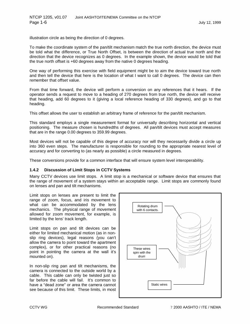
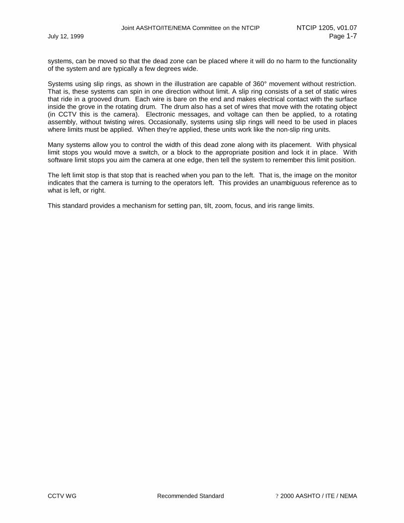
illustration circle as being the direction of 0 degrees. To make the coordinate system of the pan/tilt mechanism match the true north direction, the device must be told what the difference, or True North Offset, is between the direction of actual true north and the direction that the device recognizes as 0 degrees. In the example shown, the device would be told that the true north offset is +60 degrees away from the native 0 degrees heading. One way of performing this exercise with field equipment might be to aim the device toward true north and then tell the device that here is the location of what I want to call 0 degrees. The device can then remember that offset value. From that time forward, the device will perform a conversion on any references that it hears. If the operator sends a request to move to a heading of 270 degrees from true north, the device will receive that heading, add 60 degrees to it (giving a local reference heading of 330 degrees), and go to that heading. This offset allows the user to establish an arbitrary frame of reference for the pan/tilt mechanism. This standard employs a single measurement format for universally describing horizontal and vertical positioning. The measure chosen is hundredths of degrees. All pan/tilt devices must accept measures that are in the range 0.00 degrees to 359.99 degrees. Most devices will not be capable of this degree of accuracy nor will they necessarily divide a circle up into 360 even steps. The manufacturer is responsible for rounding to the appropriate nearest level of accuracy and for converting to (as nearly as possible) a circle measured in degrees. These conversions provide for a common interface that will ensure system level interoperability. 1.4.2 Discussion of Limit Stops in CCTV Systems Many CCTV devices use limit stops. A limit stop is a mechanical or software device that ensures that the range of movement of a system stays within an acceptable range. Limit stops are commonly found on lenses and pan and tilt mechanisms. Limit stops on lenses are present to limit the range of zoom, focus, and iris movement to what can be accommodated by the lens mechanics. The physical range of movement allowed for zoom movement, for example, is limited by the lens’ track length. Limit stops on pan and tilt devices can be either for limited mechanical motion (as in non-slip ring devices), legal reasons (you can’t allow the camera to point toward the apartment complex), or for other practical reasons (no point in pointing the camera at the wall it’s mounted on). In non-slip ring pan and tilt mechanisms, the camera is connected to the outside world by a cable. This cable can only be twisted just so far before the cable will fail. It’s common to have a “dead zone” or area the camera cannot see because of this limit. These limits, in most
Static wires
Rotating drum with 6 contacts.
These wires spin with the
drum
Joint AASHTO/ITE/NEMA Committee on the NTCIP NTCIP 1205, v01.07 July 12, 1999 Page 1-7
CCTV WG Recommended Standard ? 2000 AASHTO / ITE / NEMA
systems, can be moved so that the dead zone can be placed where it will do no harm to the functionality of the system and are typically a few degrees wide. Systems using slip rings, as shown in the illustration are capable of 360° movement without restriction. That is, these systems can spin in one direction without limit. A slip ring consists of a set of static wires that ride in a grooved drum. Each wire is bare on the end and makes electrical contact with the surface inside the grove in the rotating drum. The drum also has a set of wires that move with the rotating object (in CCTV this is the camera). Electronic messages, and voltage can then be applied, to a rotating assembly, without twisting wires. Occasionally, systems using slip rings will need to be used in places where limits must be applied. When they’re applied, these units work like the non-slip ring units. Many systems allow you to control the width of this dead zone along with its placement. With physical limit stops you would move a switch, or a block to the appropriate position and lock it in place. With software limit stops you aim the camera at one edge, then tell the system to remember this limit position. The left limit stop is that stop that is reached when you pan to the left. That is, the image on the monitor indicates that the camera is turning to the operators left. This provides an unambiguous reference as to what is left, or right. This standard provides a mechanism for setting pan, tilt, zoom, focus, and iris range limits.

NTCIP 1205, v01.07 Joint AASHTO/ITE/NEMA Committee on the NTCIP Page 1-8 July 12, 1999
CCTV WG Recommended Standard ? 2000 AASHTO / ITE / NEMA
This Page Left Intentionally Blank

Joint AASHTO/ITE/NEMA Committee on the NTCIP NTCIP 1205, v01.07 July 12, 1999 Page 2-1
CCTV WG Recommended Standard ? 2000 AASHTO / ITE / NEMA
Section 2 GENERAL
2.1 SCOPE
The communications between an ITS Management Center or portable computer and an Closed Circuit Television (CCTV) Camera Controller is accomplished by using the NTCIP Application Layer services to convey requests to access or modify values of CCTV Camera Control objects resident in the device via an NTCIP network. An NTCIP message consists of a specific Application Layer service and a set of data objects. An NTCIP message may be conveyed using any NTCIP defined class of service that has been specified to be compatible with the Simple Transportation Management Framework (STMF). The scope of this document is limited to the functionality related to CCTV Camera Control within a transportation environment. This publication defines objects which are specific to CCTV and also defines standardized object Groups which can be used for conformance statements. The limits and descriptions of the parameters are established to give the user maximum flexibility to operate devices that either exist at the time this document was authored or may exist in the future. 2.2 REFERENCES
For approved revisions, contact: NTCIP Coordinator
National Electrical Manufacturers Association 1300 North 17th Street, Suite 1847
Rosslyn, VA 22209-3801
For proposed revisions, which are under discussion by the relevant NTCIP Working Group, and revisions recommended by the NTCIP Joint Committee are available on the World Wide Web at http://www.ntcip.org. The following standards (normative references) contain provisions that, through reference in this text, constitute provisions of this Standard. Other documents and standards (other references) are referenced in these documents, which might provide a complete understanding of the entire protocol and the relations between all parts of the protocol. At the time of publication, the editions indicated were valid. All standards are subject to revision, and parties to agreements based on this Standard are encouraged to investigate the possibility of applying the most recent editions of each standard listed below. 2.2.1 Normative References
NEMA TS 3.4-1996 National Transportation Communications for ITS Protocol – Global Object Definitions
RFC1212 03/26/1991 Concise MIB Definitions
RFC1213 03/1991 Management Information Base for Network Management of TCP/IP-based Internets: MIB-II.
RFC1155 05/10/1990 Structure and Identification of Management Information for TCP/IP-based Internets
NTCIP 1205, v01.07 Joint AASHTO/ITE/NEMA Committee on the NTCIP Page 2-2 July 12, 1999
CCTV WG Recommended Standard ? 2000 AASHTO / ITE / NEMA
2.2.2 Other References
2.2.2.1 NEMA Standards NEMA TS 3.2-1996 National Transportation Communications and ITS Protocol – Simple
Transportation Management Framework
NEMA TS 3.3-1996 National Transportation Communications for ITS Protocol – Class B Profile
ISO/IEC 8824-1995 Information Technology - Open Systems Interconnection - Specification of Abstract Syntax Notation One (ASN.1)
ISO/IEC 8825-1995 Information Technology - Open Systems Interconnection - Specification of Basic Encoding Rules for Abstract Syntax Notation One (ASN.1)
RFC1157 05/10/1990 A Simple Network Management Protocol (SNMP).
2.2.2.2 Texts David Perkins and Evan McGinnis, Understanding SNMP MIBs, New Jersey, Prentice Hall PTR, 1997, ISBN 0-13-437708-7.
2.2.3 Contact Information
2.2.3.1 ISO/IEC Standards Members of the ISO maintain registers of currently valid ISO/IEC International Standards. For the USA, the member of ISO is the American National Standards Institute (ANSI), which may be contacted as follows:
ANSI 11 West 42nd Street, 13th Floor
New York, New York 10036 (212) 642-4900
2.2.3.2 RFC Documents Electronic copies of RFC documents may be obtained using “anonymous” FTP to the host nic.ddn.mil or ds.internic.net. Printed copies are available from:
DDN Network Information Center 14200 Park Meadow Drive
Suite 200 Chantilly, VA 22021
(800) 365-3642 (703) 802-4535
2.3 TERMS
For the purposes of this standard, the following terms and definitions apply. For terms not defined in this clause, English words are used in accordance with their definitions in the latest edition of Webster's New Collegiate Dictionary. Electrical and electronic terms not defined in this clause or in Webster's New Collegiate Dictionary are used in accordance with their definitions in IEEE Std 100-1992.
Absolute A measure of pan, tilt, or zoom movement specified as the number of degrees relative to home position.
Alarm An abnormal system condition that typically requires acknowledgement and correction by trained personnel.
Joint AASHTO/ITE/NEMA Committee on the NTCIP NTCIP 1205, v01.07 July 12, 1999 Page 2-3
CCTV WG Recommended Standard ? 2000 AASHTO / ITE / NEMA
Automatic Pan (Scan) Continuous, automatic horizontal back and forth motion of a camera.
Auto Focus The process of automatically adjusting the lens focus to provide a sharp image on the faceplate of the camera pickup device.
Auto Iris Lens A lens where the aperture automatically opens or closes to maintain proper light levels on the faceplate of the camera pickup device.
Camera Power The power supply delivered to the camera necessary for proper operation.
CCTV Closed Circuit Television, any television system that transmits video information over a hardwire medium such as coax, fiber optic, twisted pair cable.
CCU
Camera Control Unit. A device used to multiplex and distribute multiple camera motion and lens position control inputs to multiple cameras. CCTV is also a distribution system that limits reception of an image to those receivers or monitors which are directly connected to the organization point by coaxial cable or microwave link.
Delta A measurement in degrees of pan, tilt, zoom movement specified as the difference between an initial and final position.
Focus The process of sharpening a blurred image on a screen, monitor, or any display; adjusting picture to achieve the greatest possible resolution.
Heater A device used to maintain a constant camera enclosure temperature. A heater is typically thermostatically controlled and is used in harsh viewing environments.
Home Position An arbitrary pan, tilt, and zoom position defined by the camera vendor. The home position represents a mechanical reference point from which camera and lens position parameters are measured.
Iris
A device used to control the amount of light that reaches the imaging sensor. The amount of light transmitted through a lens is controlled by an adjustable diaphram, or iris, located in the lens barrel. The opening is referred to as the aperture, and the size of the aperture is controlled by rotating the aperture control ring on the lens barrel. The graduations on the lens barrel are expressed in terms of the focal length for the lens divided by the diameter of the aperture at that setting. This ratio is called the f-number.
Label Text information embedded in the video and displayed on a monitor.
Lens An assembly of optical components, usually made from glass, used to focus light on an imaging device.
Manual Focus The process of manually adjusting the lens focus to provide a sharp image on the faceplate of the camera pickup device.
Manual Iris Lens A lens in which the aperture is manually opened or closed to maintain proper light levels on the faceplate of the camera pickup device.
Octet Encoding A variation of Basic Encoding Rules (BER) developed for low

NTCIP 1205, v01.07 Joint AASHTO/ITE/NEMA Committee on the NTCIP Page 2-4 July 12, 1999
CCTV WG Recommended Standard ? 2000 AASHTO / ITE / NEMA
Rules bandwidth communications links.
Pan Movement of the camera in a horizontal direction.
Preset
A pre-specified position where a camera is pointed to a fixed point in space. A preset includes pan, tilt, and zoom parameters. Presets are typically programmed by manually adjusting the camera position and lens zoom setting followed by initiating a save command from the camera control system.
Sequential Switcher A video control device that switches multiple video inputs to multiple video outputs in a predetermined timed sequence.
Switcher
Term often used to describe a special effects generator; a unit that allows the operator to switch between video camera signals. Switchers are often used in industrial applications to switch between video cameras monitoring certain areas for display on one monitor.
Tilt The movement of a camera in a vertical direction.
VTR Video Tape Recorder, the term "VTR" includes reel-to-reel and cassette type.
Video
Pertaining to picture signals in a television system. (A): any production using videotape or television technology. (B): Television and the technical equipment and events involved in creating television. (C): The picture portion of a television broadcast. (D): Non-broadcast or private television.
Zone A region in space defined by pan and tilt limits. A zone is typically identified by a pre-programmed text message that is displayed to the user when the center of the camera's field of view is within the zone.
Zoom The process of mechanically or electronically adjusting the focal length of a lens from wide angle through telephoto.
2.4 ACRONYMS
The following acronyms are widely used in either the Transportation or CCTV industry. For additional information, please refer to the extended glossary in Informative Annex A.
AASHTO American Association of State Highway and Transportation Officials
ACTV Advanced Compatible Television
ADTV Advanced Definition Television
AFC Automatic Frequency Control
AGC Automatic Gain Control
AIV Advanced Level Control Video
ALC Automatic Level Control or Automatic Light Control
ASC Automatic Sensitivity Control
CATV Community Antenna Television
CAV Component Analog Video
CCD Charge-Coupled Device
Joint AASHTO/ITE/NEMA Committee on the NTCIP NTCIP 1205, v01.07 July 12, 1999 Page 2-5
CCTV WG Recommended Standard ? 2000 AASHTO / ITE / NEMA
CCTV Closed Circuit Television
CCU Camera Control Unit
CD Compact Disc
CD+G Compact Disc+Graphics
CD-I Compact Disc-Interactive
CD-IV Compact Disc-Interactive Video
CD+MIDI Compact Disc-Musical Instrument Digital Interface
CD-ROM Compact Disc-Read Only Memory
CLUT Color Look-Up Table
EDTV Enhanced Definition Television also Extended Definition Television
HDTV High-Definition Television
IAB Internet Advisory Board
ITE Institute of Transportation Engineers
ITS Intelligent Transportation Systems
LLTV Low Light Television
MIB Management Information Base
NEMA National Electrical Manufacturers Association
NTCIP National Transportation Communications for ITS Protocol
NTSC National Television System Committee
OER Octet Encoding Rules
PAL Phase Alternate by Line
PAL-M Phase Alternate by Line (Brazilian standard)
RFC Request for Comment
RGB Red, Green, Blue
SECAM SEquetial Couleur A Memoire
STD Standard
VDA Video Distribution Amplifier
VITC Vertical Interval Time Code
VTR Video Tape Recorder
2.5 SUPPLEMENTAL FIGURES
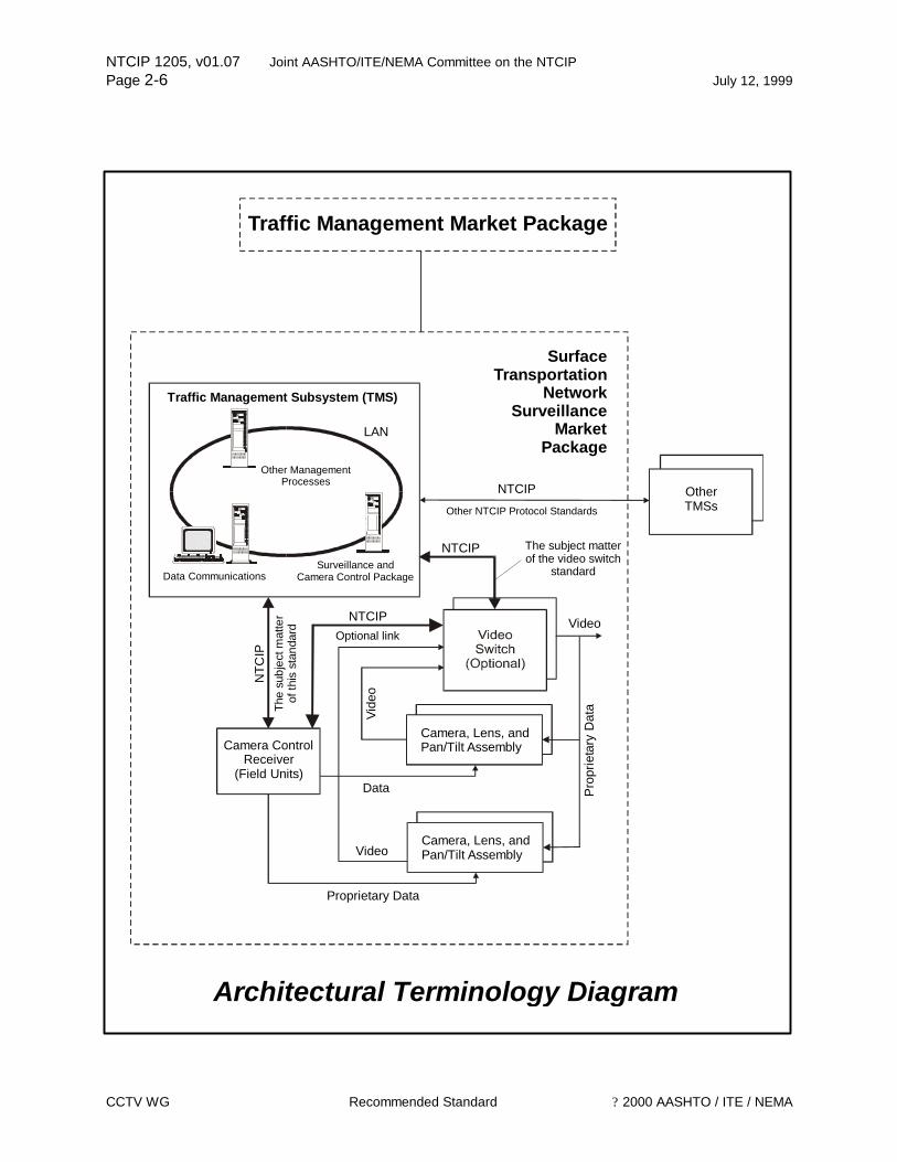
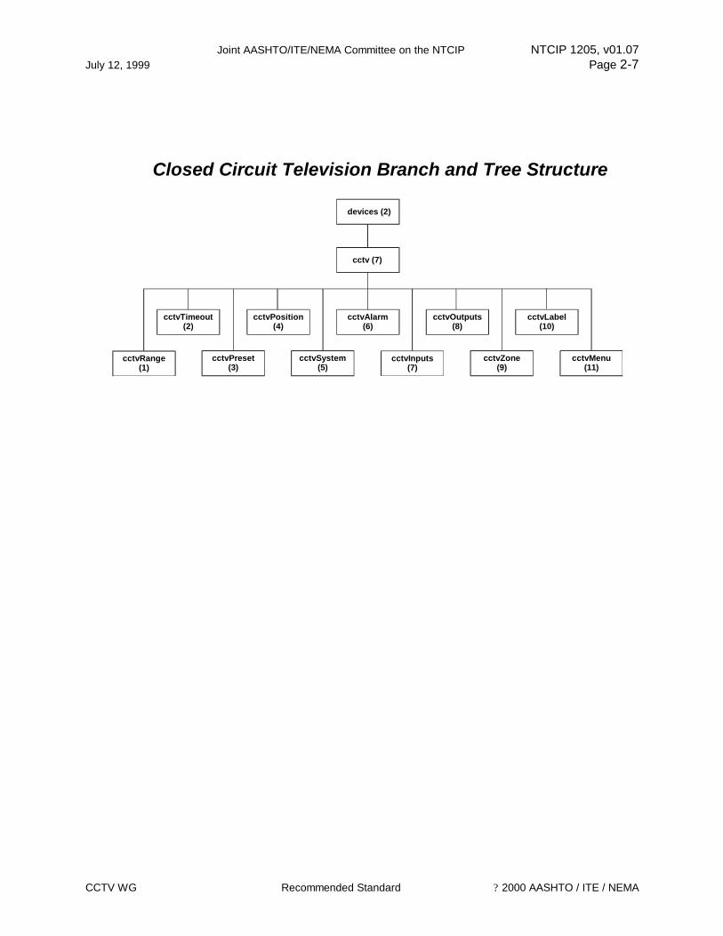
The following two figures provide a pictorial representation of the CCTV Camera Control architecture and the Closed Circuit Television Branch and Tree Structure. This is an architecture that is a proposed component for the National ITS Architecture. The architecture diagram identifies some of the terms and acronyms described above, in addition to identifying the focus of this standard. The tree structure identifies how the object definitions are combined under specific nodes.
NTCIP 1205, v01.07 Joint AASHTO/ITE/NEMA Committee on the NTCIP Page 2-6 July 12, 1999
CCTV WG Recommended Standard ? 2000 AASHTO / ITE / NEMA
Traffic Management Market Package
Traffic Management Subsystem (TMS)
OtherTMSs
Camera ControlReceiver
(Field Units)
Other NTCIP Protocol Standards
NTCIP
Video
NTCIP
Camera, Lens, and Pan/Tilt Assembly
Vide
o
Video
NTC
IP
SurfaceTransportation
NetworkSurveillance
MarketPackage
Proprietary Data
Data
Other ManagementProcesses
LAN
Data CommunicationsSurveillance and
Camera Control Package
The subject matterof the video switch
standard
The
subj
ect m
atte
rof
this
sta
ndar
d
Camera, Lens, and Pan/Tilt Assembly
Architectural Terminology Diagram
Pro
prie
tary
Dat
a
NTCIPOptional link
Joint AASHTO/ITE/NEMA Committee on the NTCIP NTCIP 1205, v01.07 July 12, 1999 Page 2-7
CCTV WG Recommended Standard ? 2000 AASHTO / ITE / NEMA
devices (2)
cctvMenu(11)
cctvRange(1)
cctvTimeout(2)
cctvPreset(3)
cctv (7)
cctvSystem(5)
cctvPosition(4)
cctvOutputs(8)
cctvInputs(7)
cctvAlarm(6)
cctvZone(9)
cctvLabel(10)
Closed Circuit Television Branch and Tree Structure

NTCIP 1205, v01.07 Joint AASHTO/ITE/NEMA Committee on the NTCIP Page 2-8 July 12, 1999
CCTV WG Recommended Standard ? 2000 AASHTO / ITE / NEMA
This Page Left Intentionally Blank

Joint AASHTO/ITE/NEMA Committee on the NTCIP NTCIP 1205, v01.07 July 12, 1999 Page 3-1
CCTV WG Recommended Standard ? 2000 AASHTO / ITE / NEMA
Section 3 CCTV MIB
This section defines those objects that are expected to be used by closed circuit television (CCTV) camera control. The objects are described in terms of the ASN.1 (defined in ISO/IEC 8824-1, ISO/IEC 8824-2, ISO/IEC 8824-3, and ISO/IEC 8824-4) macro OBJECT-TYPE. The OBJECT-TYPE macro is defined in RFC 1212. The text provided from Clause 3.1 through the end of the section (except the clause headings) constitutes the NTCIP Standard CCTV Camera Control MIB. The clauses below present the objects in lexigraphical order of their OBJECT IDENTIFIERS that correspond to their physical location within the global naming tree. The objects defined in this document reside under the “cctv” node of the global naming tree. To aid in object management, the “cctv” node has been subdivided into logical categories, each defined by a node under the “cctv” node. The individual objects are then located under the appropriate node. Nodes should not be confused with conformance groups, which are defined in Section 4. A conformance group is a logical grouping of objects that is used for conformance statements. While conformance groups will frequently correspond to the nodal structure, a conformance group may contain objects that are not lexigraphically ordered. 3.1 CLOSED CIRCUIT TELEVISION (CCTV) OBJECTS
CCTV-MIB1 DEFINITIONS ::= BEGIN --the following OBJECT IDENTIFIERS are used in the CCTV MIB: IMPORTS OBJECT-TYPE FROM RFC-1212 profiles, devices FROM TMIB; PositionReference ::= OCTET STRING (SIZE (0..4)) -- PositionReference consists of those parameters required to -- control the detailed movement of the camera. It is defined by an -- aligned OER encoded value of the following structure: -- CHOICE { -- stopMovement INTEGER (0) – stop movement, -- delta SpeedOffset, -- absolute SpeedOffset, -- continuous INTEGER (-127..127) – scalar values where larger values denote increasing
speed} -- -- SpeedOffset ::= SEQUENCE { -- speed INTEGER (-127..127), -- offset INTEGER (0..65535)} -- For the purpose of this section, the following OBJECT IDENTIFIERS are used: cctv OBJECT IDENTIFIER ::= {devices 7}
NTCIP 1205, v01.07 Joint AASHTO/ITE/NEMA Committee on the NTCIP Page 3-2 July 12, 1999
CCTV WG Recommended Standard ? 2000 AASHTO / ITE / NEMA
3.2 CCTV RANGE OBJECTS
cctvRange OBJECT IDENTIFIER ::= { cctv 1 } 3.2.1 Maximum Number of Presets Parameter rangeMaximumPreset OBJECT-TYPE SYNTAX INTEGER (0..255) ACCESS read-only STATUS mandatory DESCRIPTION "A preset is the pre-specified position where a camera is pointed to a fixed point in space (includes positions for pan, tilt, and zoom). The maximumPreset is a number indicating the total number of possible preset positions supported by the device. A value of zero (0) identifies that the device does not support presets." ::= {cctvRange 1} 3.2.2 Pan Left Limit Parameter rangePanLeftLimit OBJECT-TYPE SYNTAX INTEGER (0..35999 | 65535) ACCESS read-only STATUS mandatory DESCRIPTION "Specifies the panning left range limit in 1/100th degree units in a clockwise direction from the Home Position. If the rangePanLeftLimit and the rangePanRightLimit are both zero (0), then the device does not support panning movement. If the rangePanLeftLimit and the rangePanRightLimit are both 65535, then the device does not support the concept of right and left limits.” ::= { cctvRange 2} 3.2.3 Pan Right Limit Parameter rangePanRightLimit OBJECT-TYPE SYNTAX INTEGER (0..35999 | 65535) ACCESS read-only STATUS mandatory DESCRIPTION "Specifies the panning right range limit in 1/100th degree units in a clockwise direction from the Home Position. If the rangePanLeftLimit and the rangePanRightLimit are both zero (0), then the device does not support panning movement. If the rangePanLeftLimit and the rangePanRightLimit are both 65535, then the device does not support the concept of right and left limits." ::= { cctvRange 3} 3.2.4 Pan Home Position Parameter rangePanHomePosition OBJECT-TYPE SYNTAX INTEGER (0..35999 | 65535) ACCESS read-only STATUS mandatory DESCRIPTION "Specifies an arbitrary point on a circle from which the left and right limits are measured in 1/100th degree units. The value of 65535 means that Home position referencing is not supported for the horizontal plane.." ::= { cctvRange 4} 3.2.5 True North Offset Parameter
Joint AASHTO/ITE/NEMA Committee on the NTCIP NTCIP 1205, v01.07 July 12, 1999 Page 3-3
CCTV WG Recommended Standard ? 2000 AASHTO / ITE / NEMA
rangeTrueNorthOffset OBJECT-TYPE SYNTAX INTEGER (0..35999 | 65535) ACCESS read-write STATUS mandatory DESCRIPTION "Specifies the offset between true North and the Home Position in 1/100th degree units. When read, returns last value written. If the Home Position is True North, then set this value to zero (0). The value of 65535 means that a true North offset from the Home position is not supported.” ::= { cctvRange 5} 3.2.6 Tilt Up Limit Parameter rangeTiltUpLimit OBJECT-TYPE SYNTAX INTEGER (0..35999 | 65535) ACCESS read-only STATUS mandatory DESCRIPTION "Specifies the tilting up range limit in 1/100th degree units. The zero point for measurement is the horizon line. Tilting upward indicates a positive direction. If the rangeTiltUpLimit and the rangeTiltDownLimit are both zero (0), then the device does not support tilting movement. If the rangeTiltUpLimit and the rangeTiltDownLimit are both 65535, then the device does not support the concept of up and down limits." ::= { cctvRange 6} 3.2.7 Tilt Down Limit Parameter rangeTiltDownLimit OBJECT-TYPE SYNTAX INTEGER (0..35999 | 65535) ACCESS read-only STATUS mandatory DESCRIPTION "Specifies the tilting down range limit in 1/100th degree units. The zero point for measurement is the horizon line. Tilting upward indicates a positive direction. If the rangeTiltUpLimit and the rangeTiltDownLimit are both zero (0), then the device does not support tilting movement. If the rangeTiltUpLimit and the rangeTiltDownLimit are both 65535, then the device does not support the concept of up and down limits." ::= { cctvRange 7} 3.2.8 Zoom Limit Parameter rangeZoomLimit OBJECT-TYPE SYNTAX INTEGER (0..65535) ACCESS read-only STATUS mandatory DESCRIPTION "Specifies the zoom range in arbitrary units. Used for absolute or offset control. Zero (0) identifies that zoom limits are not supported. This number represents the scalar zoom positioning beginning with zero (0) for wide and ending with 65535 for telephoto.” ::= { cctvRange 8} 3.2.9 Focus Limit Parameter rangeFocusLimit OBJECT-TYPE SYNTAX INTEGER (0..65535) ACCESS read-only STATUS mandatory DESCRIPTION "Specifies the focus range in arbitrary units. Used for absolute or offset control. Zero (0)
NTCIP 1205, v01.07 Joint AASHTO/ITE/NEMA Committee on the NTCIP Page 3-4 July 12, 1999
CCTV WG Recommended Standard ? 2000 AASHTO / ITE / NEMA
identifies that focus limits are not supported. This number represents the scalar focus positioning beginning with zero (0) for near and ending with 65535 for far.” ::= { cctvRange 9} 3.2.10 Iris Limit Parameter rangeIrisLimit OBJECT-TYPE SYNTAX INTEGER (0..65535) ACCESS read-only STATUS mandatory DESCRIPTION "Specifies the iris range in arbitrary units. Used for absolute or offset control. Zero (0) identifies that iris limits are not supported. This number represents the scalar zoom positioning beginning with zero (0) for open and ending with 65535 for closed.” ::= { cctvRange 10} 3.2.11 Maximum Pan Step Angle Parameter rangeMinimumPanStepAngle OBJECT-TYPE SYNTAX INTEGER (0..35999 | 65535) ACCESS read-only STATUS mandatory DESCRIPTION "Specifies the minimum incremental angle in 1/100th degree units for the minimum pan step size to guarantee movement in the horizontal plane. A value of 65535 means that Minimum pan step angle is not supported.” ::= { cctvRange 11} 3.2.12 Maximum Tilt Step Angle Parameter rangeMinimumTiltStepAngle OBJECT-TYPE SYNTAX INTEGER (0..35999 | 65535) ACCESS read-only STATUS mandatory DESCRIPTION "Specifies the minimum incremental angle in 1/100th degree units for the minimum tilt step size to guarantee movement in the vertical plane. A value of 65535 means that minimum tilt step angle is not supported.” ::= { cctvRange 12} 3.3 CCTV TIMEOUT OBJECTS
cctvTimeout OBJECT IDENTIFIER ::= { cctv 2 } 3.3.1 Pan Timeout Parameter timeoutPan OBJECT-TYPE SYNTAX INTEGER (0..65535) ACCESS read-write STATUS mandatory DESCRIPTION "A number indicating the total number of milliseconds that a panning motion can continue without a reissue of a pan command. A value of zero identifies that panning timeout is not supported." ::= {cctvTimeout 1}
Joint AASHTO/ITE/NEMA Committee on the NTCIP NTCIP 1205, v01.07 July 12, 1999 Page 3-5
CCTV WG Recommended Standard ? 2000 AASHTO / ITE / NEMA
3.3.2 Tile Timeout Parameter timeoutTilt OBJECT-TYPE SYNTAX INTEGER (0..65535) ACCESS read-write STATUS mandatory DESCRIPTION "A number indicating the total number of milliseconds that a tilting motion can continue without a reissue of a tilt command. A value of zero identifies that tilting timeout is not supported." ::= {cctvTimeout 2} 3.3.3 Zoom Timeout Parameter timeoutZoom OBJECT-TYPE SYNTAX INTEGER (0..65535) ACCESS read-write STATUS mandatory DESCRIPTION "A number indicating the total number of milliseconds that a zoom motion can continue without a reissue of a zoom command. A value of zero identifies that zooming timeout is not supported." ::= {cctvTimeout 3} 3.3.4 Focus Timeout Parameter timeoutFocus OBJECT-TYPE SYNTAX INTEGER (0..65535) ACCESS read-write STATUS mandatory DESCRIPTION "A number indicating the total number of milliseconds that a focus motion can continue without a reissue of a focus type command. A value of zero identifies that focusing timeout is not supported." ::= {cctvTimeout 4} 3.3.5 Iris Timeout Parameter timeoutIris OBJECT-TYPE SYNTAX INTEGER (0..65535) ACCESS read-write STATUS mandatory DESCRIPTION "A number indicating the total number of milliseconds that an iris motion can continue without a reissue of a iris type command. A value of zero identifies that iris timeout is not supported." ::= {cctvTimeout 5} 3.4 CCTV PRESET OBJECTS
cctvPreset OBJECT IDENTIFIER ::= { cctv 3 } 3.4.1 Go To Preset Position Parameter presetGotoPosition OBJECT-TYPE SYNTAX INTEGER (0..255) ACCESS read-write STATUS mandatory DESCRIPTION "Writing to this object commands the device to move to a preset if that preset exists.
NTCIP 1205, v01.07 Joint AASHTO/ITE/NEMA Committee on the NTCIP Page 3-6 July 12, 1999
CCTV WG Recommended Standard ? 2000 AASHTO / ITE / NEMA
Reading returns the last value written. This value is reset to zero (0) upon the issuance of a pan, tilt, or zoom command." ::= {cctvPreset 1} 3.4.2 Store Preset Position Parameter presetStorePosition OBJECT-TYPE SYNTAX INTEGER (0..255) ACCESS read-write STATUS mandatory DESCRIPTION "Writing to this object commands the device to save the current position to the specified preset. Reading returns the last value written. This value is reset to zero (0) upon the issuance of a pan, tilt, or zoom command." ::= {cctvPreset 2} 3.5 CCTV POSITIONING OBJECTS
cctvPosition OBJECT IDENTIFIER ::= { cctv 4 } 3.5.1 Pan Position Parameter positionPan OBJECT-TYPE SYNTAX PositionReference ACCESS read-write STATUS mandatory DESCRIPTION "Object is 4 bytes in length:
Byte 1 is the mode of operation defined as stop movement, delta, absolute, or continuous movement,
Byte 2 is speed defined as a scalar unit with positive (+) being clockwise and negative (–) being counterclockwise, Bytes 3 and 4 specify a position or offset measurement in 1/100th degrees.
The minimum amount of movement shall be one step as defined by the rangeMinimumPanStepAngle.” ::= {cctvPosition 1} 3.5.2 Tilt Position Parameter positionTilt OBJECT-TYPE SYNTAX PositionReference ACCESS read-write STATUS mandatory DESCRIPTION "Object is 4 bytes in length:
Byte 1 is the mode of operation defined as stop movement, delta, absolute, or continuous movement,
Byte 2 is speed defined as a scalar unit with positive (+) being up and negative (–) being down, Bytes 3 and 4 specify a position or offset measurement in 1/100th degrees.
The minimum amount of movement shall be one step as defined by the rangeMinimumTiltStepAngle.” ::= {cctvPosition 2} 3.5.3 Lens Zoom Position Parameter positionZoomLens OBJECT-TYPE SYNTAX PositionReference ACCESS read-write

Joint AASHTO/ITE/NEMA Committee on the NTCIP NTCIP 1205, v01.07 July 12, 1999 Page 3-7
CCTV WG Recommended Standard ? 2000 AASHTO / ITE / NEMA
STATUS mandatory DESCRIPTION "Object is 4 bytes in length:
Byte 1 is the mode of operation defined as stop movement, delta, absolute, or continuous movement,
Byte 2 is speed defined as a scalar unit with positive (+) being telephoto and negative (–) being wide, Bytes 3 and 4 specify a position or offset measurement in scalar units with a maximum value of the specified limit.”
::= {cctvPosition 3} 3.5.4 Lens Focus Position Parameter positionFocusLens OBJECT-TYPE SYNTAX PositionReference ACCESS read-write STATUS mandatory DESCRIPTION "Object is 4 bytes in length:
Byte 1 is the mode of operation defined as stop movement, delta, absolute, or continuous movement,
Byte 2 is speed defined as a scalar unit with positive (+) being far and negative (–) being near, Bytes 3 and 4 specify a position or offset measurement in scalar units with a maximum value of the specified limit.”
::= {cctvPosition 4} 3.5.5 Lens Iris Position Parameter positionIrisLens OBJECT-TYPE SYNTAX PositionReference ACCESS read-write STATUS mandatory DESCRIPTION "Object is 4 bytes in length:
Byte 1 is the mode of operation defined as stop movement, delta, absolute, or continuous movement,
Byte 2 is speed defined as a scalar unit with positive (+) being closed and negative (–) being opened, Bytes 3 and 4 specify a position or offset measurement in scalar units with a maximum value of the specified limit.”
::= {cctvPosition 5} 3.6 CCTV SYSTEM FEATURE CONTROL OBJECTS
cctvSystem OBJECT IDENTIFIER ::= {cctv 5} 3.6.1 System Camera Feature Control Parameter systemCameraFeatureControl OBJECT-TYPE SYNTAX OCTET STRING (SIZE(2)) ACCESS read-write STATUS mandatory DESCRIPTION "A bit mapped value as defined below:
Byte1 Bit7 0 = OFF, 1 = ON for Camera Power (MSB), Bit6 0 = OFF, 1 = ON for Heater Power,
NTCIP 1205, v01.07 Joint AASHTO/ITE/NEMA Committee on the NTCIP Page 3-8 July 12, 1999
CCTV WG Recommended Standard ? 2000 AASHTO / ITE / NEMA
Bit5 0 = OFF, 1 = ON for Wiper, Bit4 0 = OFF, 1 = ON for Washer, Bit3 0 = OFF, 1 = ON for Blower, Bits2..0 Reserved (Bit0 = LSB),
Byte 2 Bit7 0 = OFF, 1 = ON for activation and deactivation of the camera component
(MSB), Bits6..0 Reserved (Bit0 = LSB)."
::= {cctvSystem 1} 3.6.2 System Camera Feature Status systemCameraFeatureStatus OBJECT-TYPE SYNTAX OCTET STRING (SIZE(1)) ACCESS read-only STATUS mandatory DESCRIPTION "A bit mapped value as defined below:
Byte1 Bit7 0 = OFF, 1 = ON for status of Camera Power (MSB), Bit6 0 = OFF, 1 = ON for status of Heater Power, Bit5 0 = OFF, 1 = ON for status of Wiper, Bit4 0 = OFF, 1 = ON for status of Washer, Bit3 0 = OFF, 1 = ON for status of Blower, Bits2..0 Reserved (Bit0 = LSB),"
::= {cctvSystem 2} 3.6.3 System Camera Equipment Availability Parameter systemCameraEquipped OBJECT-TYPE SYNTAX OCTET STRING (SIZE(1)) ACCESS read-write STATUS mandatory DESCRIPTION "A bit mapped value as defined below:
Bit7 0 = NO, 1 = YES denotes the availability of Camera Power (MSB), Bit6 0 = NO, 1 = YES denotes the availability of Heater Power, Bit5 0 = NO, 1 = YES denotes the availability of a Wiper, Bit4 0 = NO, 1 = YES denotes the availability of a Washer, Bit3 0 = NO, 1 = YES denotes the availability of a Blower, Bits2..0 Reserved (Bit0 = LSB).
When read, this object returns last value written." ::= {cctvSystem 3} 3.6.4 System Lens Feature Control Parameter systemLensFeatureControl OBJECT-TYPE SYNTAX OCTET STRING (SIZE(2)) ACCESS read-write STATUS mandatory DESCRIPTION "A bit mapped value as defined below:
Byte1 Bit 7 0 = OFF, 1 = ON for Auto Iris, Bit 6 0 = OFF, 1 = ON for Auto Focus, Bits5..0 Reserved (Bit 0 = LSB),
Joint AASHTO/ITE/NEMA Committee on the NTCIP NTCIP 1205, v01.07 July 12, 1999 Page 3-9
CCTV WG Recommended Standard ? 2000 AASHTO / ITE / NEMA
Byte2 Bit7 0 = OFF, 1 = ON for activation and deactivation of the lens component (MSB), Bits6..0 Reserved (Bit0 = LSB)." ::= {cctvSystem 4} 3.6.5 System Lens Feature Status Parameter systemLensFeatureStatus OBJECT-TYPE SYNTAX OCTET STRING (SIZE(1)) ACCESS read-write STATUS mandatory DESCRIPTION "A bit mapped value as defined below:
Bit 7 0 = OFF, 1 = ON for Auto Iris, Bit 6 0 = OFF, 1 = ON for Auto Focus, Bits5..0 Reserved (Bit 0 = LSB),"
::= {cctvSystem 5} 3.6.6 System Lens Equipment Availability Parameter systemLensEquipped OBJECT-TYPE SYNTAX OCTET STRING (SIZE(1)) ACCESS read-write STATUS mandatory DESCRIPTION "A bit mapped value as defined below:
Bit 7 0 = NO, 1 = YES denotes the availability of Auto Iris, Bit 6 0 = NO, 1 = YES denotes the availability of Auto Focus, Bits5..0 Reserved (Bit 0 = LSB)."
::= {cctvSystem 6} 3.7 CCTV ALARM OBJECTS
cctvAlarm OBJECT IDENTIFIER ::= { cctv 6 } 3.7.1 Alarm Status Parameter alarmStatus OBJECT-TYPE SYNTAX OCTET STRING (SIZE(1)) ACCESS read-only STATUS mandatory DESCRIPTION "Alarm status denotes a bit mapped value that indicates the current status of alarms, as outlined below:
Bit7 0 = OFF, 1 = ON for the active status of the Cabinet Alarm signifying cabinet entry (MSB),
Bit6 0 = OFF, 1 = ON for the active status of the Enclosure Alarm signifying enclosure entry,
Bit5 0 = OFF, 1 = ON for the active status of the Video Loss Alarm signifying presence of video sync,
Bit4 0 = OFF, 1 = ON for the active status of the Temperature Alarm signifying a value outside the allowable threshold range for internal camera enclosure temperature,
Bit3 0 = OFF, 1 = ON for the active status of the Pressure Alarm signifying a current value outside the allowable threshold range for the internal camera enclosure pressure,
NTCIP 1205, v01.07 Joint AASHTO/ITE/NEMA Committee on the NTCIP Page 3-10 July 12, 1999
CCTV WG Recommended Standard ? 2000 AASHTO / ITE / NEMA
Bit2 0 = Local, 1 = Remote for the active status of the Local/Remote Alarm, Bit1 0 = OFF, 1 = ON for the active status of the Washer Fluid Alarm signifying a
current value outside the allowable threshold range for the washer fluid capacity, Bit0 Reserved (LSB).”
::= {cctvAlarm 1} 3.7.2 Alarm Latch Status Parameter alarmLatchStatus OBJECT-TYPE SYNTAX OCTET STRING (SIZE (1)) ACCESS read-only STATUS mandatory DESCRIPTION "Latch status denotes a bit mapped value that indicates the presence of a latched alarm, indicating that an alarm has occurred since the previous latch was cleared, as outlined below:
Bit7 0 = OFF, 1 = ON for the latch status of the Cabinet Alarm (MSB), Bit6 0 = OFF, 1 = ON for the latch status of the Enclosure Alarm, Bit5 0 = OFF, 1 = ON for the latch status of the Video Loss Alarm, Bit4 0 = OFF, 1 = ON for the latch status of the Temperature Alarm, Bit3 0 = OFF, 1 = ON for the latch status of the Pressure Alarm, Bit2 0 = Local, 1 = Remote for the latch status of the Local/Remote Alarm, Bit1 0 = OFF, 1 = ON for the latch status of the Washer Fluid Alarm, Bit0 Reserved (LSB).”
::= {cctvAlarm 2} 3.7.3 Alarm Latch Clear Parameter alarmLatchClear OBJECT-TYPE SYNTAX OCTET STRING (SIZE(1)) ACCESS read-write STATUS mandatory DESCRIPTION "Latch clear denotes a bit mapped value that clears the presence of a latched alarm, as outlined below:
Bit7 0 = OFF, 1 = ON for clearing the alarm latch for the Cabinet Alarm (MSB), Bit6 0 = OFF, 1 = ON for clearing the alarm latch for the Enclosure Alarm, Bit5 0 = OFF, 1 = ON for clearing the alarm latch for the Video Loss Alarm, Bit4 0 = OFF, 1 = ON for clearing the alarm latch for the Temperature Alarm, Bit3 0 = OFF, 1 = ON for clearing the alarm latch for the Pressure Alarm, Bit2 0 = Local, 1 = Remote for clearing the alarm latch for the Local/Remote Alarm, Bit1 0 = OFF, 1 = ON for clearing the alarm latch for the Washer Fluid Alarm, Bit0 Reserved (LSB).”
::= {cctvAlarm 3} 3.7.4 Temperature Alarm High-Low Threshold alarmTemparatureHighLowThreshold OBJECT-TYPE SYNTAX OCTET STRING (SIZE(2)) ACCESS read-write STATUS mandatory DESCRIPTION “Identifies the high and low thresholds for the temperature alarm, as shown below;
Byte1 Low Threshold denotes the value of minimum internal camera enclosure temperature measured in degrees C,
Byte2 HighThreshold denotes the value of maximum internal camera enclosure temperature measured in degrees C.”

Joint AASHTO/ITE/NEMA Committee on the NTCIP NTCIP 1205, v01.07 July 12, 1999 Page 3-11
CCTV WG Recommended Standard ? 2000 AASHTO / ITE / NEMA
::= {cctvAlarm 4} 3.7.5 Temperature Alarm Current Value Parameter alarmTemparatureCurrentValue OBJECT-TYPE SYNTAX OCTET STRING (SIZE(1)) ACCESS read-write STATUS mandatory DESCRIPTION “Identifies the current value for the temperature within the camera enclosure measured in degrees C.” ::= {cctvAlarm 5} 3.7.6 Pressure Alarm High-Low Threshold Parameter alarmPresureHighLowThreshold OBJECT-TYPE SYNTAX OCTET STRING (SIZE(2)) ACCESS read-write STATUS mandatory DESCRIPTION “Identifies the high and low thresholds for the pressure alarm, as shown below;
Byte1 Low Threshold denotes the value of minimum pressure within the camera enclosure measured in psig,
Byte2 HighThreshold denotes the value of maximum pressure within the camera enclosure measured in psig.”
::= {cctvAlarm 6} 3.7.7 Pressure Alarm Current Value Parameter alarmPresureCurrentValue OBJECT-TYPE SYNTAX OCTET STRING (SIZE(1)) ACCESS read-write STATUS mandatory DESCRIPTION “Identifies the current value for the pressure within the camera enclosure measured in psig.” ::= {cctvAlarm 7} 3.7.8 Washer Fluid Alarm High-Low Threshold Parameter alarmWasherFluidHighLowThreshold OBJECT-TYPE SYNTAX OCTET STRING (SIZE(2)) ACCESS read-write STATUS mandatory DESCRIPTION “Identifies the high and low thresholds for the washer fluid alarm, as shown below;
Byte1 Low Threshold denotes the percentage of minimum filled capacity between zero (0) and 100 percent,
Byte2 HighThreshold denotes the percentage of maximum filled capacity between zero (0) and 100 percent.”
::= {cctvAlarm 8} 3.7.9 Washer Fluid Alarm Current Value Parameter alarmWasherFluidCurrentValue OBJECT-TYPE SYNTAX OCTET STRING (SIZE(1))
NTCIP 1205, v01.07 Joint AASHTO/ITE/NEMA Committee on the NTCIP Page 3-12 July 12, 1999
CCTV WG Recommended Standard ? 2000 AASHTO / ITE / NEMA
ACCESS read-write STATUS mandatory DESCRIPTION “Identifies the current value for the washer fluid level measured as the amount of filled capacity between zero (0) and 100 percent.” ::= {cctvAlarm 9} 3.7.10 Alarm Label Index Parameter alarmLabelIndex OBJECT-TYPE SYNTAX OCTET STRING (SIZE(7)) ACCESS read-only STATUS mandatory DESCRIPTION "The label number identifies the entry into the camera control label table that provides additional text information or on-screen text information. Labels are text strings with formatting, positioning, and display information. A value of zero (0) indicates that there is no camera control label table entry for the alarm. The alarms are identified below:
Byte1 for the Cabinet Alarm, Byte2 for the Enclosure Alarm, Byte3 for the Video Loss Alarm, Byte4 for the Temperature Alarm, Byte5 for the Pressure Alarm, Byte6 for the Local/Remote Alarm, Byte7 for the Washer Fluid Alarm.”
::= {cctvAlarm 10} 3.8 CCTV DISCRETE INPUT OBJECTS
cctvInput OBJECT IDENTIFIER ::= { cctv 7 } 3.8.1 Discrete Input Status Parameter inputStatus OBJECT-TYPE SYNTAX OCTET STRING (SIZE(1)) ACCESS read-only STATUS mandatory DESCRIPTION "Input status denotes a bit mapped value that indicates the current state of eight (8) user defined discrete inputs, as outlined below:
Bit7 0 = OFF, 1 = ON for the active status of discrete Input 8 (MSB), Bit6 0 = OFF, 1 = ON for the active status of discrete Input 7, Bit5 0 = OFF, 1 = ON for the active status of discrete Input 6, Bit4 0 = OFF, 1 = ON for the active status of discrete Input 5, Bit3 0 = OFF, 1 = ON for the active status of discrete Input 4, Bit2 0 = OFF, 1 = ON for the active status of discrete Input 3, Bit1 0 = OFF, 1 = ON for the active status of discrete Input 2, Bit0 0 = OFF, 1 = ON for the active status of discrete Input 1 (LSB).”
::= {cctvInput 1} 3.8.2 Discrete Input Latch Status Parameter inputLatchStatus OBJECT-TYPE SYNTAX OCTET STRING (SIZE (1)) ACCESS read-only STATUS mandatory DESCRIPTION "Latch status denotes a bit mapped value that indicates the presence of a latched input
Joint AASHTO/ITE/NEMA Committee on the NTCIP NTCIP 1205, v01.07 July 12, 1999 Page 3-13
CCTV WG Recommended Standard ? 2000 AASHTO / ITE / NEMA
for eight (8) user defined discrete inputs, indicating that an input has occurred since the previous latch was cleared, as outlined below:
Bit7 0 = OFF, 1 = ON for the latch status of the discrete Input 8 (MSB), Bit6 0 = OFF, 1 = ON for the latch status of the discrete Input 7, Bit5 0 = OFF, 1 = ON for the latch status of the discrete Input 6, Bit4 0 = OFF, 1 = ON for the latch status of the discrete Input 5, Bit3 0 = OFF, 1 = ON for the latch status of the discrete Input 4, Bit2 0 = OFF, 1 = ON for the latch status of the discrete Input 3, Bit1 0 = OFF, 1 = ON for the latch status of the discrete Input 2, Bit0 0 = OFF, 1 = ON for the latch status of the discrete Input 1 (LSB).”
::= {cctvInput 2} 3.8.3 Discrete Input Latch Clear Parameter inputLatchClear OBJECT-TYPE SYNTAX OCTET STRING (SIZE(1)) ACCESS read-write STATUS mandatory DESCRIPTION "Latch clear denotes a bit mapped value that clears the presence of a latched input for eight (8) user defined discrete inputs, as outlined below:
Bit7 0 = OFF, 1 = ON for clearing the input latch for discrete Input 8 (MSB), Bit6 0 = OFF, 1 = ON for clearing the input latch for discrete Input 7, Bit5 0 = OFF, 1 = ON for clearing the input latch for discrete Input 6, Bit4 0 = OFF, 1 = ON for clearing the input latch for discrete Input 5, Bit3 0 = OFF, 1 = ON for clearing the input latch for discrete Input 4, Bit2 0 = OFF, 1 = ON for clearing the input latch for discrete Input 3, Bit1 0 = OFF, 1 = ON for clearing the input latch for discrete Input 2, Bit0 0 = OFF, 1 = ON for clearing the input latch for discrete Input 1 (LSB).” ::= {cctvInput 3}
3.8.4 Discrete Input Label Index Parameter inputLabelIndex OBJECT-TYPE SYNTAX OCTET STRING (SIZE(8)) ACCESS read-only STATUS mandatory DESCRIPTION "The label number identifies the entry into the camera control label table that provides additional text information or on-screen text information. Labels are text strings with formatting, positioning, and display information. A value of zero (0) indicates that there is no camera control label table entry for the input. The user defined discrete inputs are identified below:
Byte1 for the discrete Input 1, Byte2 for the discrete Input 2, Byte3 for the discrete Input 3, Byte4 for the discrete Input 4, Byte5 for the discrete Input 5, Byte6 for the discrete Input 6, Byte7 for the discrete Input 7, Byte8 for the discrete Input 8.”
::= {cctvInput 4} 3.9 CCTV DISCRETE OUTPUT OBJECTS
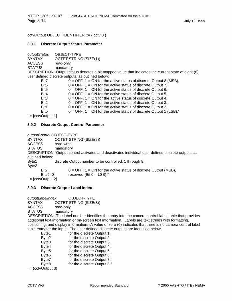
NTCIP 1205, v01.07 Joint AASHTO/ITE/NEMA Committee on the NTCIP Page 3-14 July 12, 1999
CCTV WG Recommended Standard ? 2000 AASHTO / ITE / NEMA
cctvOutput OBJECT IDENTIFIER ::= { cctv 8 } 3.9.1 Discrete Output Status Parameter outputStatus OBJECT-TYPE SYNTAX OCTET STRING (SIZE(1)) ACCESS read-only STATUS mandatory DESCRIPTION "Output status denotes a bit mapped value that indicates the current state of eight (8) user defined discrete outputs, as outlined below:
Bit7 0 = OFF, 1 = ON for the active status of discrete Output 8 (MSB), Bit6 0 = OFF, 1 = ON for the active status of discrete Output 7, Bit5 0 = OFF, 1 = ON for the active status of discrete Output 6, Bit4 0 = OFF, 1 = ON for the active status of discrete Output 5, Bit3 0 = OFF, 1 = ON for the active status of discrete Output 4, Bit2 0 = OFF, 1 = ON for the active status of discrete Output 3, Bit1 0 = OFF, 1 = ON for the active status of discrete Output 2, Bit0 0 = OFF, 1 = ON for the active status of discrete Output 1 (LSB).”
::= {cctvOutput 1} 3.9.2 Discrete Output Control Parameter outputControl OBJECT-TYPE SYNTAX OCTET STRING (SIZE(2)) ACCESS read-write STATUS mandatory DESCRIPTION "Output control activates and deactivates individual user defined discrete outputs as outlined below: Byte1 discrete Output number to be controlled, 1 through 8, Byte2
Bit7 0 = OFF, 1 = ON for the active status of discrete Output (MSB), Bits6..0 reserved (Bit 0 = LSB).”
::= {cctvOutput 2} 3.9.3 Discrete Output Label Index outputLabelIndex OBJECT-TYPE SYNTAX OCTET STRING (SIZE(8)) ACCESS read-only STATUS mandatory DESCRIPTION "The label number identifies the entry into the camera control label table that provides additional text information or on-screen text information. Labels are text strings with formatting, positioning, and display information. A value of zero (0) indicates that there is no camera control label table entry for the input. The user defined discrete outputs are identified below:
Byte1 for the discrete Output 1, Byte2 for the discrete Output 2, Byte3 for the discrete Output 3, Byte4 for the discrete Output 4, Byte5 for the discrete Output 5, Byte6 for the discrete Output 6, Byte7 for the discrete Output 7, Byte8 for the discrete Output 8.”
::= {cctvOutput 3}
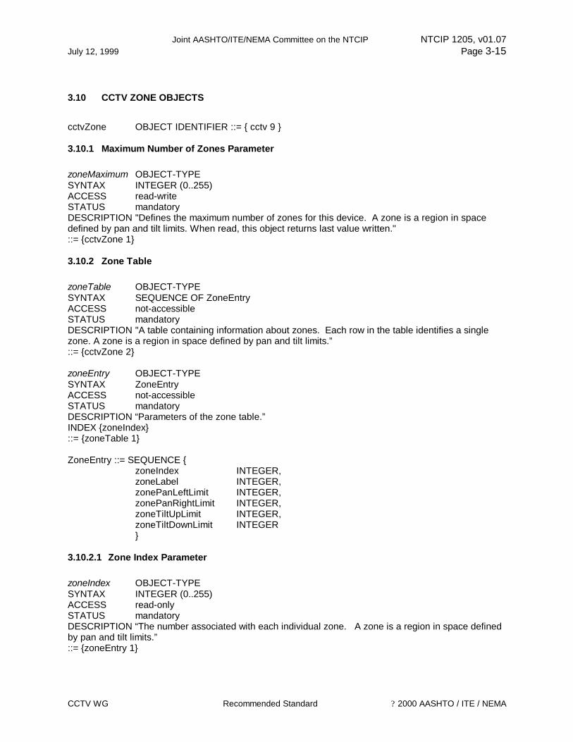
Joint AASHTO/ITE/NEMA Committee on the NTCIP NTCIP 1205, v01.07 July 12, 1999 Page 3-15
CCTV WG Recommended Standard ? 2000 AASHTO / ITE / NEMA
3.10 CCTV ZONE OBJECTS
cctvZone OBJECT IDENTIFIER ::= { cctv 9 } 3.10.1 Maximum Number of Zones Parameter zoneMaximum OBJECT-TYPE SYNTAX INTEGER (0..255) ACCESS read-write STATUS mandatory DESCRIPTION "Defines the maximum number of zones for this device. A zone is a region in space defined by pan and tilt limits. When read, this object returns last value written." ::= {cctvZone 1} 3.10.2 Zone Table zoneTable OBJECT-TYPE SYNTAX SEQUENCE OF ZoneEntry ACCESS not-accessible STATUS mandatory DESCRIPTION "A table containing information about zones. Each row in the table identifies a single zone. A zone is a region in space defined by pan and tilt limits.” ::= {cctvZone 2} zoneEntry OBJECT-TYPE SYNTAX ZoneEntry ACCESS not-accessible STATUS mandatory DESCRIPTION “Parameters of the zone table.” INDEX {zoneIndex} ::= {zoneTable 1} ZoneEntry ::= SEQUENCE { zoneIndex INTEGER,
zoneLabel INTEGER, zonePanLeftLimit INTEGER, zonePanRightLimit INTEGER, zoneTiltUpLimit INTEGER, zoneTiltDownLimit INTEGER
} 3.10.2.1 Zone Index Parameter zoneIndex OBJECT-TYPE SYNTAX INTEGER (0..255) ACCESS read-only STATUS mandatory DESCRIPTION “The number associated with each individual zone. A zone is a region in space defined by pan and tilt limits.” ::= {zoneEntry 1}
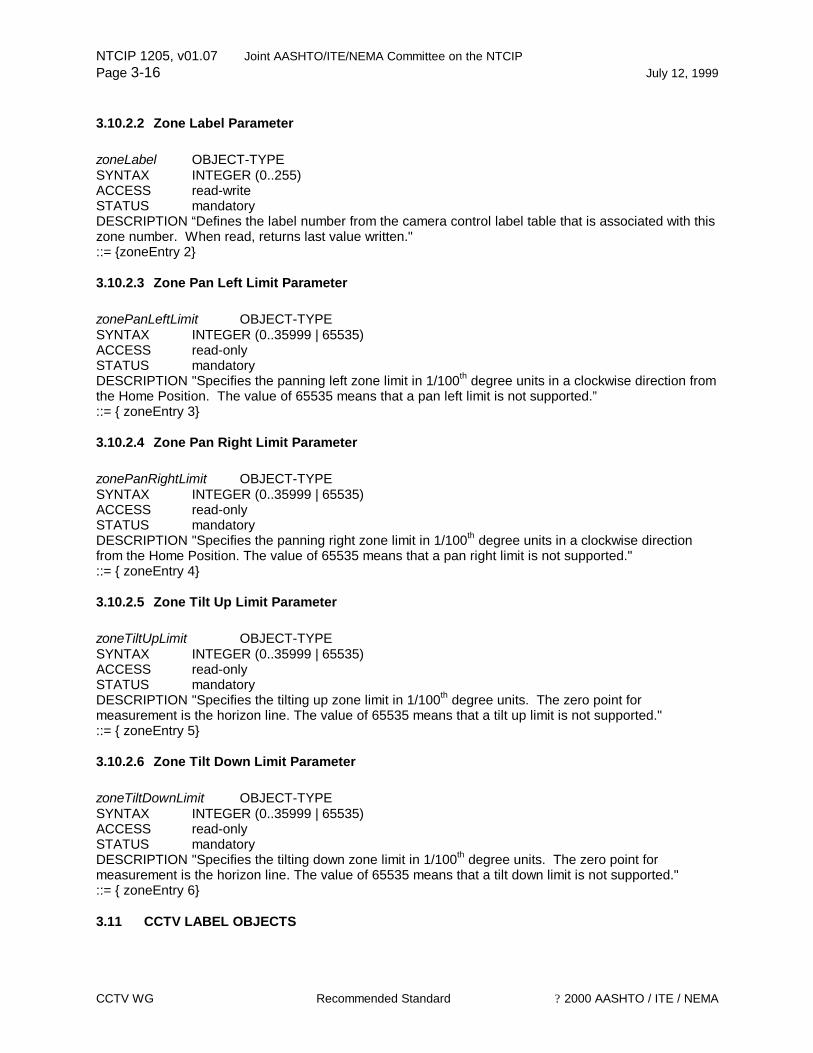
NTCIP 1205, v01.07 Joint AASHTO/ITE/NEMA Committee on the NTCIP Page 3-16 July 12, 1999
CCTV WG Recommended Standard ? 2000 AASHTO / ITE / NEMA
3.10.2.2 Zone Label Parameter zoneLabel OBJECT-TYPE SYNTAX INTEGER (0..255) ACCESS read-write STATUS mandatory DESCRIPTION “Defines the label number from the camera control label table that is associated with this zone number. When read, returns last value written." ::= {zoneEntry 2} 3.10.2.3 Zone Pan Left Limit Parameter zonePanLeftLimit OBJECT-TYPE SYNTAX INTEGER (0..35999 | 65535) ACCESS read-only STATUS mandatory DESCRIPTION "Specifies the panning left zone limit in 1/100th degree units in a clockwise direction from the Home Position. The value of 65535 means that a pan left limit is not supported.” ::= { zoneEntry 3} 3.10.2.4 Zone Pan Right Limit Parameter zonePanRightLimit OBJECT-TYPE SYNTAX INTEGER (0..35999 | 65535) ACCESS read-only STATUS mandatory DESCRIPTION "Specifies the panning right zone limit in 1/100th degree units in a clockwise direction from the Home Position. The value of 65535 means that a pan right limit is not supported." ::= { zoneEntry 4} 3.10.2.5 Zone Tilt Up Limit Parameter zoneTiltUpLimit OBJECT-TYPE SYNTAX INTEGER (0..35999 | 65535) ACCESS read-only STATUS mandatory DESCRIPTION "Specifies the tilting up zone limit in 1/100th degree units. The zero point for measurement is the horizon line. The value of 65535 means that a tilt up limit is not supported." ::= { zoneEntry 5} 3.10.2.6 Zone Tilt Down Limit Parameter zoneTiltDownLimit OBJECT-TYPE SYNTAX INTEGER (0..35999 | 65535) ACCESS read-only STATUS mandatory DESCRIPTION "Specifies the tilting down zone limit in 1/100th degree units. The zero point for measurement is the horizon line. The value of 65535 means that a tilt down limit is not supported." ::= { zoneEntry 6} 3.11 CCTV LABEL OBJECTS
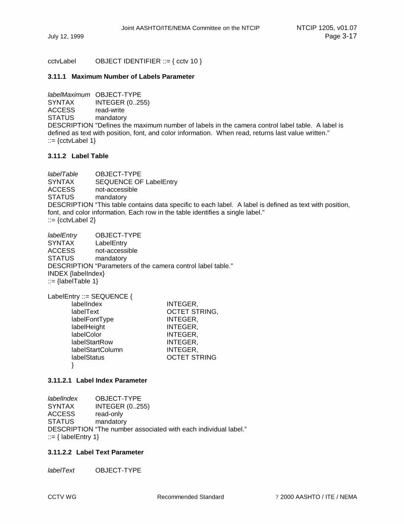
Joint AASHTO/ITE/NEMA Committee on the NTCIP NTCIP 1205, v01.07 July 12, 1999 Page 3-17
CCTV WG Recommended Standard ? 2000 AASHTO / ITE / NEMA
cctvLabel OBJECT IDENTIFIER ::= { cctv 10 } 3.11.1 Maximum Number of Labels Parameter labelMaximum OBJECT-TYPE SYNTAX INTEGER (0..255) ACCESS read-write STATUS mandatory DESCRIPTION "Defines the maximum number of labels in the camera control label table. A label is defined as text with position, font, and color information. When read, returns last value written." ::= {cctvLabel 1} 3.11.2 Label Table labelTable OBJECT-TYPE SYNTAX SEQUENCE OF LabelEntry ACCESS not-accessible STATUS mandatory DESCRIPTION “This table contains data specific to each label. A label is defined as text with position, font, and color information. Each row in the table identifies a single label." ::= {cctvLabel 2} labelEntry OBJECT-TYPE SYNTAX LabelEntry ACCESS not-accessible STATUS mandatory DESCRIPTION “Parameters of the camera control label table." INDEX {labelIndex} ::= {labelTable 1} LabelEntry ::= SEQUENCE { labelIndex INTEGER,
labelText OCTET STRING, labelFontType INTEGER, labelHeight INTEGER, labelColor INTEGER,
labelStartRow INTEGER, labelStartColumn INTEGER,
labelStatus OCTET STRING } 3.11.2.1 Label Index Parameter labelIndex OBJECT-TYPE SYNTAX INTEGER (0..255) ACCESS read-only STATUS mandatory DESCRIPTION “The number associated with each individual label.” ::= { labelEntry 1} 3.11.2.2 Label Text Parameter labelText OBJECT-TYPE

NTCIP 1205, v01.07 Joint AASHTO/ITE/NEMA Committee on the NTCIP Page 3-18 July 12, 1999
CCTV WG Recommended Standard ? 2000 AASHTO / ITE / NEMA
SYNTAX OCTET STRING (SIZE(0..255)) ACCESS read-write STATUS mandatory DESCRIPTION “Text for the label. The label text must fit within the frame-size available for the application.” ::= { labelEntry 2} 3.11.2.3 Label Font Type Parameter labelFontType OBJECT-TYPE SYNTAX INTEGER (0..255) ACCESS read-write STATUS mandatory DESCRIPTION “Designates the type of font to be displayed. Only one font style may be supported and that font style is taken to be the default style.
Value Meaning 1 designates ASCII text characters to be displayed, 2 designates Bit Mapped Characters to be displayed.”
::= { labelEntry 3} 3.11.2.4 Label Height Parameter labelHeight OBJECT-TYPE SYNTAX INTEGER (0..255) ACCESS read-write STATUS mandatory DESCRIPTION “Height of this label text scaled to a range of zero (0) and 255 to fit height of screen. A height of zero (0) indicates that a label is not displayed and a height of 255 indicates that the label is presented at a maximum height.” ::= { labelEntry 4} 3.11.2.5 Label Color Parameter labelColor OBJECT-TYPE SYNTAX INTEGER {
blue(1), green(2), cyan(3), red(4), magenta(5), brown(6), white(7), grey(8), lightBlue(9), lightGreen(10), lightCyan(11), lightRed(12), lightMagenta(13), yellow(14), brightWhite(15), black(16)}
ACCESS read-write STATUS mandatory
Joint AASHTO/ITE/NEMA Committee on the NTCIP NTCIP 1205, v01.07 July 12, 1999 Page 3-19
CCTV WG Recommended Standard ? 2000 AASHTO / ITE / NEMA
DESCRIPTION “Color of the label characters. The color is defined as follows: Value Meaning 1 blue, 2 green, 3 cyan, 4 red, 5 magenta, 6 brown, 7 white, 8 grey, 9 lightBlue, 10 lightGreen, 11 lightCyan, 12 lightRed, 13 lightMagenta, 14 yellow, 15 brightWhite, 16 black.”
::= { labelEntry 5} 3.11.2.6 Label Start Row Parameter labelStartRow OBJECT-TYPE SYNTAX INTEGER (0..255) ACCESS read-write STATUS mandatory DESCRIPTION “Start of text row number scaled to a range of zero (0) to 255. Zero (0) is designated as the upper left corner of the display.” ::= { labelEntry 6} 3.11.2.7 Label Start Column Parameter labelStartColumn OBJECT-TYPE SYNTAX INTEGER (0..255) ACCESS read-write STATUS mandatory DESCRIPTION “Start of text column number scaled to a range of zero (0) to 255. Zero (0) is designated as the upper left corner of the display.” ::= { labelEntry 7} 3.11.2.8 Label Status Parameter labelStatus OBJECT-TYPE SYNTAX OCTET STRING (SIZE(1)) ACCESS read-write STATUS mandatory DESCRIPTION “The object denotes whether or not the label is currently being displayed, as outlined below:
Bit7 0 = NO, 1 = YES denotes that the label is valid for display (MSB), Bit6 0 = OFF, 1 = ON for the display status of the label, Bits5..0 Reserved (Bit 0 = LSB).”
::= { labelEntry 8}
NTCIP 1205, v01.07 Joint AASHTO/ITE/NEMA Committee on the NTCIP Page 3-20 July 12, 1999
CCTV WG Recommended Standard ? 2000 AASHTO / ITE / NEMA
3.11.3 Label Location Parameter labelLocationLabel OBJECT-TYPE SYNTAX INTEGER (0..255) ACCESS read-write STATUS mandatory DESCRIPTION "Defines the index to the camera control label table for this camera location. The location label is commonly used to identify a street name, intersection, or other pertinent information to be displayed on a monitor. A value of zero (0) turns the location reference label off at this location. When read, this object returns last value written.” ::= {cctvLabel 3} 3.11.4 Enable Label Text Display labelEnableTextDisplay OBJECT-TYPE SYNTAX OCTET STRING (SIZE (1)) ACCESS read-write STATUS mandatory DESCRIPTION "The object provides a control mechanism for activating or deactivating all labels regardless of individual display status, as outlined below:
Bit7 0 = OFF, 1 = ON for the for controlling the display for all labels at once (MSB), Bit6..0 Reserved (Bit 0 = LSB).”
::= {cctvLabel 4} 3.12 CCTV ON-SCREEN CAMERA MENU OBJECTS
cctvMenu OBJECT IDENTIFIER ::= { cctv 11 } 3.12.1 Activate Menu Parameter menuActivate OBJECT-TYPE SYNTAX INTEGER (0..255) ACCESS read-write STATUS mandatory DESCRIPTION "Activates the internal camera menu.
Value Meaning 0 turns off the internal camera menu, 1..254 activates the internal camera menu for the number of seconds expressed by the
value indicated between 1 and 254, 255 activates the menu for an indefinite period of time.”
::= {cctvMenu 1} 3.12.2 Menu Control Parameter menuControl OBJECT-TYPE SYNTAX INTEGER { pageDown(1), pageUp(2),
cursorUp(3), cursorDown(4), cursorRight(5), cursorLeft(6), incrementValue(7) ,
Joint AASHTO/ITE/NEMA Committee on the NTCIP NTCIP 1205, v01.07 July 12, 1999 Page 3-21
CCTV WG Recommended Standard ? 2000 AASHTO / ITE / NEMA
decrementValue(8), enterValue(9), noMenu(255)}
ACCESS read-write STATUS mandatory DESCRIPTION "Object value that manipulates the internal camera menu. Basic menu manipulations are described as follows:
Value Meaning 1 Page Down, 2 Page Up, 3 Cursor Up 4 Cursor Down, 5 Cursor Right, 6 Cursor Left, 7 Increment value pointed at current cursor position, 8 Decrement value pointed at current cursor position, 9 Enter value shown, 10..254 Reserved, 255 Menu not supported by the device.”
::= {cctvMenu 2} END

NTCIP 1205, v01.07 Joint AASHTO/ITE/NEMA Committee on the NTCIP Page 3-22 July 12, 1999
CCTV WG Recommended Standard ? 2000 AASHTO / ITE / NEMA
This Page Left Intentionally Blank
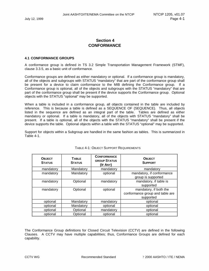
Joint AASHTO/ITE/NEMA Committee on the NTCIP NTCIP 1205, v01.07 July 12, 1999 Page 4-1
CCTV WG Recommended Standard ? 2000 AASHTO / ITE / NEMA
Section 4 CONFORMANCE
4.1 CONFORMANCE GROUPS
A conformance group is defined in TS 3.2 Simple Transportation Management Framework (STMF), clause 3.3.5, as a basic unit of conformance. Conformance groups are defined as either mandatory or optional. If a conformance group is mandatory, all of the objects and subgroups with STATUS “mandatory” that are part of the conformance group shall be present for a device to claim conformance to the MIB defining the Conformance group. If a Conformance group is optional, all of the objects and subgroups with the STATUS “mandatory” that are part of the conformance group shall be present if the device supports the Conformance group. Optional objects with the STATUS “optional” may be supported. When a table is included in a conformance group, all objects contained in the table are included by reference. This is because a table is defined as a SEQUENCE OF {SEQUENCE}. Thus, all objects listed in the sequence are defined as an integral part of the table. Tables are defined as either mandatory or optional. If a table is mandatory, all of the objects with STATUS “mandatory” shall be present. If a table is optional, all of the objects with the STATUS “mandatory” shall be present if the device supports the table. Optional objects within a table with the STATUS “optional” may be supported. Support for objects within a Subgroup are handled in the same fashion as tables. This is summarized in Table 4-1.
TABLE 4-1: OBJECT SUPPORT REQUIREMENTS
OBJECT STATUS
TABLE STATUS
CONFORMANCE GROUP STATUS
(IF ANY)
OBJECT SUPPORT
mandatory Mandatory mandatory mandatory mandatory Mandatory optional mandatory, if conformance
group is supported mandatory Optional mandatory mandatory, if table is
supported mandatory Optional optional mandatory, if both the
conformance group and table are supported
optional Mandatory mandatory optional optional Mandatory optional optional optional Optional mandatory optional optional Optional optional optional
The Conformance Group definitions for Closed Circuit Television (CCTV) are defined in the following Clauses. A CCTV may have multiple capabilities; thus, Conformance Groups are defined for each capability.

NTCIP 1205, v01.07 Joint AASHTO/ITE/NEMA Committee on the NTCIP Page 4-2 July 12, 1999
CCTV WG Recommended Standard ? 2000 AASHTO / ITE / NEMA
4.1.1 CCTV Configuration Conformance Group The Configuration Conformance Group consists of objects that specify the configuration parameters of a CCTV. The conformance requirement for each object within the group is shown. Please refer to the Conformance Statement Table 4-2 for the conformance requirement for the group. The Configuration Conformance Group shall consist of the following objects:
OBJECT OR TABLE NAME REFERENCE CONFORMANCE REQUIREMENT
WITHIN THE GROUP rangeMaximumPreset NTCIP CCTV v01.05 mandatory rangePanLeftLimit NTCIP CCTV v01.05 mandatory rangePanRightLimit NTCIP CCTV v01.05 mandatory rangePanHomePosition NTCIP CCTV v01.05 mandatory trueNorthOffset NTCIP CCTV v01.05 mandatory rangeTiltUpLimit NTCIP CCTV v01.05 mandatory rangeTiltDownLimit NTCIP CCTV v01.05 mandatory rangeZoomLimit NTCIP CCTV v01.05 mandatory rangeFocusLimit NTCIP CCTV v01.05 mandatory rangeIrisLimit NTCIP CCTV v01.05 mandatory rangeMinimumPanStepAngle NTCIP CCTV v01.05 mandatory rangeMinimumTiltStepAngle NTCIP CCTV v01.05 mandatory timeoutPan NTCIP CCTV v01.05 mandatory timeoutTilt NTCIP CCTV v01.05 mandatory timeoutZoom NTCIP CCTV v01.05 mandatory timeoutFocus NTCIP CCTV v01.05 mandatory timeoutIris NTCIP CCTV v01.05 mandatory labelMaximum NTCIP CCTV v01.05 mandatory labelTable NTCIP CCTV v01.05 mandatory labelEntry NTCIP CCTV v01.05 mandatory labelIndex NTCIP CCTV v01.05 mandatory labelText NTCIP CCTV v01.05 mandatory labelFontType NTCIP CCTV v01.05 mandatory labelHeight NTCIP CCTV v01.05 mandatory labelColor NTCIP CCTV v01.05 mandatory labelStartRow NTCIP CCTV v01.05 mandatory labelStartColumn NTCIP CCTV v01.05 mandatory labelStatus NTCIP CCTV v01.05 mandatory labelLocationLabel NTCIP CCTV v01.05 mandatory labelEnableTextDisplay NTCIP CCTV v01.05 mandatory
4.1.2 Extended Functions Conformance Group The Features Conformance Group consists of objects that specify features within a CCTV. The conformance requirement for each object within the group is shown. Please refer to the Conformance Statement Table 4-2 for the conformance requirement for the group. The Features Conformance Group shall consist of the following objects:

Joint AASHTO/ITE/NEMA Committee on the NTCIP NTCIP 1205, v01.07 July 12, 1999 Page 4-3
CCTV WG Recommended Standard ? 2000 AASHTO / ITE / NEMA
OBJECT OR TABLE NAME REFERENCE CONFORMANCE REQUIREMENT
WITHIN THE GROUP systemCameraFeatureControl NTCIP CCTV v01.05 mandatory systemCameraFeatureStatus NTCIP CCTV v01.05 mandatory systemCameraEquipped NTCIP CCTV v01.05 mandatory systemLensFeatureControl NTCIP CCTV v01.05 mandatory systemLensFeatureStatus NTCIP CCTV v01.05 mandatory systemLensEquipped NTCIP CCTV v01.05 mandatory alarmStatus NTCIP CCTV v01.05 mandatory alarmLatchStatus NTCIP CCTV v01.05 mandatory alarmLatchClear NTCIP CCTV v01.05 mandatory alarmTemperatureHighLowThreshold NTCIP CCTV v01.05 mandatory alarmTemperatureCurrentValue NTCIP CCTV v01.05 mandatory alarmPressureHighLowThreshold NTCIP CCTV v01.05 mandatory alarmPressureCurrentValue NTCIP CCTV v01.05 mandatory alarmWasherFluidHighLowThreshold NTCIP CCTV v01.05 mandatory alarmWasherFluidCurrentValue NTCIP CCTV v01.05 mandatory alarmLabelIndex NTCIP CCTV v01.05 mandatory inputStatus NTCIP CCTV v01.05 mandatory inputLatchStatus NTCIP CCTV v01.05 mandatory inputLatchClear NTCIP CCTV v01.05 mandatory inputLabelIndex NTCIP CCTV v01.05 mandatory outputStatus NTCIP CCTV v01.05 mandatory outputControl NTCIP CCTV v01.05 mandatory outputLabelIndex NTCIP CCTV v01.05 mandatory zoneMaximum NTCIP CCTV v01.05 mandatory zoneTable NTCIP CCTV v01.05 mandatory zoneIndex NTCIP CCTV v01.05 mandatory zoneLabel NTCIP CCTV v01.05 mandatory zonePanLeftLimit NTCIP CCTV v01.05 mandatory zonePanRightLimit NTCIP CCTV v01.05 mandatory zoneTiltUpLimit NTCIP CCTV v01.05 mandatory zoneTiltDownLimit NTCIP CCTV v01.05 mandatory
4.1.3 Motion Control Conformance Group The Motion Control Conformance Group consists of objects that specify features within a CCTV. The conformance requirement for each object within the group is shown. Please refer to the Conformance Statement Table 4-2 for the conformance requirement for the group. The Motion Control Conformance Group shall consist of the following objects:
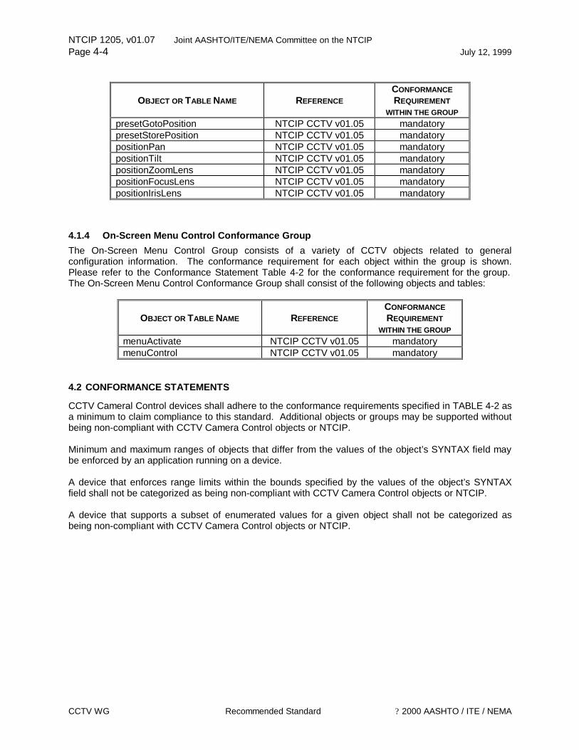
NTCIP 1205, v01.07 Joint AASHTO/ITE/NEMA Committee on the NTCIP Page 4-4 July 12, 1999
CCTV WG Recommended Standard ? 2000 AASHTO / ITE / NEMA
OBJECT OR TABLE NAME REFERENCE CONFORMANCE REQUIREMENT
WITHIN THE GROUP presetGotoPosition NTCIP CCTV v01.05 mandatory presetStorePosition NTCIP CCTV v01.05 mandatory positionPan NTCIP CCTV v01.05 mandatory positionTilt NTCIP CCTV v01.05 mandatory positionZoomLens NTCIP CCTV v01.05 mandatory positionFocusLens NTCIP CCTV v01.05 mandatory positionIrisLens NTCIP CCTV v01.05 mandatory
4.1.4 On-Screen Menu Control Conformance Group The On-Screen Menu Control Group consists of a variety of CCTV objects related to general configuration information. The conformance requirement for each object within the group is shown. Please refer to the Conformance Statement Table 4-2 for the conformance requirement for the group. The On-Screen Menu Control Conformance Group shall consist of the following objects and tables:
OBJECT OR TABLE NAME REFERENCE CONFORMANCE REQUIREMENT
WITHIN THE GROUP menuActivate NTCIP CCTV v01.05 mandatory menuControl NTCIP CCTV v01.05 mandatory
4.2 CONFORMANCE STATEMENTS
CCTV Cameral Control devices shall adhere to the conformance requirements specified in TABLE 4-2 as a minimum to claim compliance to this standard. Additional objects or groups may be supported without being non-compliant with CCTV Camera Control objects or NTCIP. Minimum and maximum ranges of objects that differ from the values of the object’s SYNTAX field may be enforced by an application running on a device. A device that enforces range limits within the bounds specified by the values of the object’s SYNTAX field shall not be categorized as being non-compliant with CCTV Camera Control objects or NTCIP. A device that supports a subset of enumerated values for a given object shall not be categorized as being non-compliant with CCTV Camera Control objects or NTCIP.
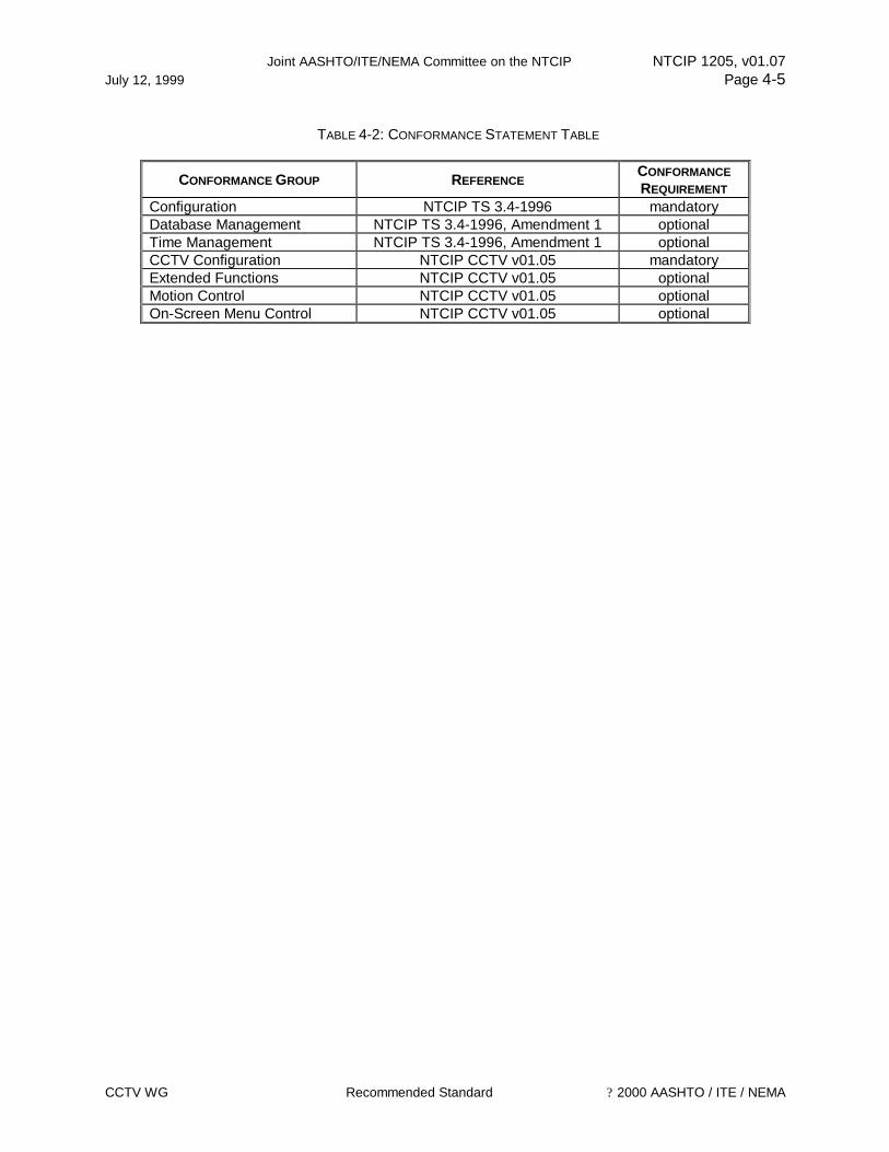
Joint AASHTO/ITE/NEMA Committee on the NTCIP NTCIP 1205, v01.07 July 12, 1999 Page 4-5
CCTV WG Recommended Standard ? 2000 AASHTO / ITE / NEMA
TABLE 4-2: CONFORMANCE STATEMENT TABLE
CONFORMANCE GROUP REFERENCE CONFORMANCE REQUIREMENT
Configuration NTCIP TS 3.4-1996 mandatory Database Management NTCIP TS 3.4-1996, Amendment 1 optional Time Management NTCIP TS 3.4-1996, Amendment 1 optional CCTV Configuration NTCIP CCTV v01.05 mandatory Extended Functions NTCIP CCTV v01.05 optional Motion Control NTCIP CCTV v01.05 optional On-Screen Menu Control NTCIP CCTV v01.05 optional

NTCIP 1205, v01.07 Joint AASHTO/ITE/NEMA Committee on the NTCIP Page 4-6 July 12, 1999
CCTV WG Recommended Standard ? 2000 AASHTO / ITE / NEMA
This Page Left Intentionally Blank

Joint AASHTO/ITE/NEMA Committee on the NTCIP NTCIP 1205, v01.06 July 12, 1999 Page A-1
CCTV WG Recommended Standard ? 2000 AASHTO / ITE / NEMA
Informative Annex A EXTENDED GLOSSARY
Aberrations Certain aberrations degrade the image formed by a lens.
A/B Editing Video editing using two source recorders.
A/B Roll Editing A technique by which selected odd (A-roll) and even (B-roll) audio/video sequences from two VCRs are then dubbed onto a third tape usually a composite master.
A/B Split Screen A useful means for comparing two sources simultaneously. Permits a fast visual check of the phase and sync timing between two inputs.
Ablation Optical memory data writing technique in which laser burns pits onto a metal film.
Achromatic Completely colorless white light.
Active Line The horizontal scan lines which produce a television picture. In the NTSC system in the US, there are 525 active lines.
Active Program The length of audio and video program material on the master videotape not to exceed the one-side capacity of a videodisc.
Active Video Lines All video not occurring in the horizontal and vertical blanking intervals.
ACTV1 A channel/receiver compatible system with increased resolution.
ACTV2 Similar to ACTV1 but with improved audio and still more advanced resolution.
Advanced Compatible Television (ACTV)
Advanced television transmission system; currently two such systems exist.
Advanced Interactive Video (AIV)
A format for storing analog and digital video images, digital sound and data on a single laser disc.
Advanced Television (ATV)
Including several versions of improved or higher quality television, including HDTV, IDTV, EDTV, and several other television systems considered better than the currently available and used systems.
Aliasing Undersirable "beating" effects caused by sampling frequencies being too low to faithfully reproduce image detail.
Alpha Channel A portion of each display pixel representing the combined video and graphic image data for a video digitizer component.
Alphageometric A videotex graphics format in which shapes are defined by geometric elements such as points and lines.
Alphamosaic Graphics
A videotex graphics format in which pictures are composed of small character sized blocks.
Analog Video A video signal that represents an infinite number of gradations between given video levels.

NTCIP 1205, v01.07 Joint AASHTO/ITE/NEMA Committee on the NTCIP Page A-2 July 12, 1999
CCTV WG Recommended Standard ? 2000 AASHTO / ITE / NEMA
Anamorphic A type of lens adapter designed to produce a wide screen image from an equally condensed image on the film.
Aperture The opening of a lens which controls the amount of light reaching the surface of the pickup device. The size of the aperture is controlled by the iris adjustment. By increasing the f stop number (f/1.4, f/1.8, f/2.8, etc.) less light is permitted to pass to the pickup device.
Aspect Ratio The proportions of a projected picture area in terms of relative height and width values. In the U.S., standard video aspect ratio is four units wide by three units high, usually shown as 4:3.
Astigmatism The uneven foreground and background blur that is in the image.
Asymmetrical Compression
An image compression system which takes more processing to compress the image than it does to extract or decompress it.
Auto Brightness Control
The electronic circuit which controls the brightness of the display device as a function of ambient light.
Automatic Frequency Control (AFC)
An electronic circuit used whereby the frequency of an oscillator is automatically maintained within specified limits.
Automatic Gain Control (AGC)
An electronic circuit used by which the gain of a signal is automatically adjusted as a function of its input or other specified parameter.
Automatic Light Control (ALC)
The process by which the illumination incident upon the face of the pickup device is automatically adjusted as a function of the brightness of the scene.
Automatic Pan (Scan)
Continuous, automatic horizontal back and forth motion of a camera.
Automatic Sensitivity Control (ASC)
(A) Electronic circuit which varies the sensitivity of the system as a function of automatic target control, automatic light controls, other specified control parameters, or any combination thereof. (B) Detects light intensity and keeps camera in optimum working condition as it applies to light input.
Automatic Iris Lens A lens in which the aperture automatically opens or closes to maintain proper light levels on the faceplate of the camera pickup device.
Automatic Light Control (ALC)
A circuit used in audio and video recorders to control the level of the recorded signal automatically to provide uniform level without distortion due to overloading. Also called Automatic Gain Control (AGC). An ALC Defeat control permits manual level control for wide ranges or special recording purposes.
Back Light A fixture that is often not properly applied or overlooked completely. The main function of the back light is to separate the individual subjects from the background and give them depth and dimension.
Barrel Distortion The distortion of a scene which occurs when a wide-angle lens is used; edges appear rounded and out of proportion with the center of the image.
Base and Fill Lights Commonly referred to as "scoops" provide a soft-edged field of light which is used to provide basic illumination of the subject. to fill in the areas not highlighted by the key light, to illuminate the background

Joint AASHTO/ITE/NEMA Committee on the NTCIP NTCIP 1205, v01.06 July 12, 1999 Page A-3
CCTV WG Recommended Standard ? 2000 AASHTO / ITE / NEMA
and to soften shadowed caused by key lights.
Blackburst A composite color video signal. This signal has composite sync, reference burst, and a black video signal which is usually at a level of 7.5 IRE 1 .05V) above the blanking level. (B) Fade-to-Black between scenes.
Black Level The level of the video signal that corresponds to the maximum limits of the black areas of the picture.
Blanking Related to composite sync. This signal has both horizontal and vertical components and is at its negative level whenever video is to be blanked or turned off.
Blanking Level It is the level of a video signal which separates the range that contains the picture information from the range that contains the synchronizing information.
Bloom Unacceptable TV picture caused by too much light.
Brightness Achromatic intensity, relative lighting without regard to color; light emitted from a surface such as a screen measured in foot-lamberts, foot-candles, or lux.
Brightness Ratio The difference between the brightest and darkest object in a scene. Too extreme a difference can lead to an unacceptable contrast ratio.
Brightness Signal Same as the luminance signal (Y); the signal which carries information about the amount of light at each point in the image.
Burst In color TV reception, the signal that serves as the reference for the 3.58 MHz oscillator; it occurs during video blanking.
Character Generator Reproduces recognized font styles from a computer type keyboard-usually provides multiple screen storage and is capable of background colorization from video display.
Charge-Coupled Device (CCD)
Semiconductor devices arrayed so that the electric charge at the output of one provides the input stimulus to the next. More compact and efficient than cathode ray tubes.
Chroma The color information contained in a video signal, consisting of hue (phase angle) and saturation (amplitude) of the color subcarrier.
Chroma Keying The process of overlaying one video signal over another, the areas of overlay being defined by a specific range of color, or chrominance, one of the signals. For this process to work, the chrominance must have sufficient resolution, or bandwidth. Coded (composite) video systems do not have sufficient bandwidth for acceptable quality chroma keying, hence analog chroma keyers typically use RGB sources.
Chrominance The color part of a signal, relating to the hue and saturation but not to the brightness or luminance of the signal, e.g. black, gray and white, have no chrominance, but any colored signal has both chrominance and luminance. U,V: Cr,Cb: 1,Q:(R-Y), (B-Y) represent the chrominance information of a signal.
Clipping The process of shearing off the peaks of either the white or the black excursions of the video signal.
Closed Circuit A distribution system which limits reception of an image to those receivers or monitors which are directly connected to the origination
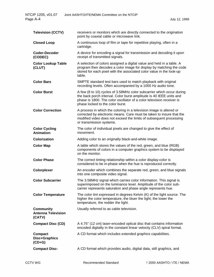
NTCIP 1205, v01.07 Joint AASHTO/ITE/NEMA Committee on the NTCIP Page A-4 July 12, 1999
CCTV WG Recommended Standard ? 2000 AASHTO / ITE / NEMA
Television (CCTV) receivers or monitors which are directly connected to the origination point by coaxial cable or microwave link.
Closed Loop A continuous loop of film or tape for repetitive playing, often in a cartridge.
Coder-Decoder (CODEC)
A device for encoding a signal for transmission and decoding it upon receipt of transmitted signals.
Color Lookup Table (CLUT)
A selection of colors assigned a digital value and held in a table. A program then decodes a color image for display by matching the code stored for each pixel with the associated color value in the look-up table.
Color Bars SMPTE standard test bars used to match playback with original recording levels. Often accompanied by a 1000 Hz audio tone.
Color Burst A few (8 to 10) cycles of 3.58MHz color subcarrier which occur during the back porch interval. Color burst amplitude is 40 IEEE units and phase is 1800. The color oscillator of a color television receiver is phase locked to the color burst.
Color Correction A process in which the coloring in a television image is altered or corrected by electronic means. Care must be taken to insure that the modified video does not exceed the limits of subsequent processing or transmission systems.
Color Cycling Animation
The color of individual pixels are changed to give the effect of movement.
Colorization Adding color to an originally black-and-white image.
Color Map A table which stores the values of the red, green, and blue (RGB) components of colors in a computer graphics system to be displayed on the monitor.
Color Phase The correct timing relationship within a color display-color is considered to be in-phase when the hue is reproduced correctly.
Colorplexer An encoder which combines the separate red, green, and blue signals into one composite video signal.
Color Subcarrier The 3.58MHz signal which carries color information. This signal is superimposed on the luminance level. Amplitude of the color sub- carrier represents saturation and phase angle represents hue.
Color Temperature The color tint expressed in degrees Kelvin (K) of the light source. The higher the color temperature, the bluer the light; the lower the temperature, the redder the light.
Community Antenna Television (CATV)
Usually referred to as cable television.
Compact Disc (CD) A 4.75" (12 cm) laser-encoded optical disc that contains information encoded digitally in the constant linear velocity (CLV) spiral format.
Compact Disc+Graphics (CD+G)
A CD format which includes extended graphics capabilities.
Compact Disc- A CD format which provides audio, digital data, still graphics, and limited motion video. The standard for this format is known as the

Joint AASHTO/ITE/NEMA Committee on the NTCIP NTCIP 1205, v01.06 July 12, 1999 Page A-5
CCTV WG Recommended Standard ? 2000 AASHTO / ITE / NEMA
Interactive (CD-I) limited motion video. The standard for this format is known as the Green Book.
Compact Disc-Interactive Video (CD-IV)
A CD format which provides audio, digital data, still graphics, and full-screen, full-motion video.
Compact Disc-Music Instrument Digital Interface (CD+MIDI)
A CD format which provides digital audio, graphics information, and the musical instrument digital interface (MIDI) specifications and capabilities.
Compact Disc-Read Only Memory
A 4.75" (12 cm) laser-encoded optical memory storage medium that contains information encoded digitally in the constant linear velocity (CLV) spiral format. The standards for this format are known as the Yellow Book.
Component Analog Video (CAV)
Unencoded video signals which can provide greater color resolution. An NTSC encoder must be used to read the signals so they may be recognized by a standard NTSC receiver.
Compatible Color A video broadcast system which separates the luminance and chrominance signals so that the signal may be received by either a color or black and white receiver.
Component The normal interpretation of a component video signal is one in which the luminance and chrominance are sent as separate components.
Component Video The separation of chrominance and luminance parts of the video signal. These two component signals are recorded separately.
Composite A composite video signal is one in which the luminance and chrominance information have been combined using one of the coding standards: NTSC, PAL, SECAM.
Composite Sync A signal consisting of horizontal sync pulses, vertical syncpulses, and equalizing pulses only, with a no-signal reference level.
Composite Video Signals
The complete visual wave form of the color video signal composed of chromatic and luminance picture information; blanking pedestal; field, line, and color sync pulses; and field equalizing pulses.
Compressed Video A video image or segment that has been digitally processed using a variety of algorithms and other techniques to reduce the amount of space required to store the digital information.
Contrast (A) The range of light and dark values in a picture or the ratio between the maximum and the minimum brightness values. Low contrast is shown mainly as shades of gray, while high contrast is shown as blacks and whites with very little gray. (B) A TV monitor adjustment which increases or decreases the level of contrast of a televised picture.
Contrast Range The range of grays in a video image, usually a ratio of light to dark. Contrast Ratio The ratio of brightness of the brightest possible area to the darkest
possible area of an image. Convergence Proper alignment of the vertical and horizontal lines, as in video
projection. Cross Color This defect manifests itself as spurious rainbow patterns on highly
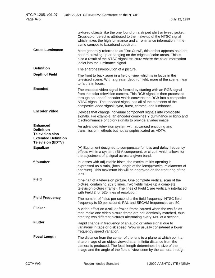
NTCIP 1205, v01.07 Joint AASHTO/ITE/NEMA Committee on the NTCIP Page A-6 July 12, 1999
CCTV WG Recommended Standard ? 2000 AASHTO / ITE / NEMA
textured objects like the one found on a striped shirt or tweed jacket. Cross-color defect is attributed to the make-up of the NTSC signal which mixes the high luminance and chrominance information in the same composite baseband spectrum.
Cross Luminance More generally referred to as "Dot Crawl", this defect appears as a dot pattern crawling up or hanging on the edges of color areas. This is also a result of the NTSC signal structure where the color information leaks into the luminance signal.
Definition The sharpness/resolution of a picture. Depth of Field The front to back zone in a field of view which is in focus in the
televised scene. With a greater depth of field, more of the scene, near to far, is in focus.
Encoded The encoded video signal is formed by starting with an RGB signal from the color television camera. This RGB signal is then processed through an I and 0 encoder which converts the RGB into a composite NTSC signal. The encoded signal has all of the elements of the composite video signal: sync, burst, chroma, and luminance.
Encoder Video Devices that change individual component signals into composite signals. For example, an encoder combines Y (luminance or light) and C (chrominance or color) signals to provide a video image.
Enhanced Definition Television also Extended Definition Television (EDTV)
An advanced television system with advanced encoding and transmission methods but not as sophisticated as HDTV.
Equalizer (A) Equipment designed to compensate for loss and delay frequency effects within a system. (B) A component, or circuit, which allows for the adjustment of a signal across a given band.
f /number In lenses with adjustable irises, the maximum iris opening is expressed as a ratio, (focal length of the lens)/(maximum diameter of aperture). This maximum iris will be engraved on the front ring of the lens.
Field One-half of a television picture. One complete vertical scan of the picture, containing 262.5 lines. Two fields make up a complete television picture (frame). The lines of Field 1 are vertically interlaced with Field 2 for 525 lines of resolution.
Field Frequency The number of fields per second is the field frequency; NTSC field frequency is 60 per second; PAL and SECAM frequencies are 50.
Flicker A video effect on a still or frozen frame caused when the two fields that make one video picture frame are not identically matched, thus creating two different pictures alternating every 1/60 of a second.
Flutter Rapid change in frequency of an audio or video signal due to variations in tape or disk speed. Wow is usually considered a lower frequency speed variation.
Focal Length The distance from the center of the lens to a plane at which point a sharp image of an object viewed at an infinite distance from the camera is produced. The focal length determines the size of the image and the angle of the field of view seen by the camera through
Joint AASHTO/ITE/NEMA Committee on the NTCIP NTCIP 1205, v01.06 July 12, 1999 Page A-7
CCTV WG Recommended Standard ? 2000 AASHTO / ITE / NEMA
the lens. That is the distance from the center of the lens to the pickup device.
Focus Sharpening a blurred image on a screen, monitor, or any display; adjusting picture to achieve the greatest possible resolution.
Focus, Automatic A device on slide projectors whereby after focusing the first image, remaining similarly-mounted slides are automatically focused.
Foot Candle The amount of light reflected by a surface one foot from a lighted candle. Metric equivalent is lux.
Foot Lambert One lumen or one foot candle of light over a one square foot surface. Format, Video Current formats include C, U-Matic, Betacam, M, Betacam SP, M-11,
DI, D2, Beta, VHS, Hi8, 8mm and S-VHS. Frame (A) The total area of the picture which is scanned while the picture
signal is not blanked. (B) A complete TV picture consisting of two fields; a total scanning of all 525 lines of the raster area; occurs every 1/30 of a second. (625 lines, 1/25 sec. in Europe and many other countries).
Frame Rate The speed at which video frames are scanned or displayed; 30 frames a second for NTSC; 25 frames a second for PAL/SECAM.
Genlock Genlock is a process of sync generator locking. This is usually performed by introducing a composite video signal from a master source to the subject sync generator. The generator to be locked has circuits to isolate vertical drive, horizontal drive and subcarrier. The process then involves locking the subject sync generator to the master subcarrier, horizontal, and vertical drives so that the result is that both sync generators are running at the same frequency and phase.
Ghost A shadowy or weak image in the received picture, offset either to the right or to the left of the primary image. It is the result of transmission conditions where secondary signals are created and received earlier or later than the primary signal caused by a reflected RF signal.
Gray Scale A series of tones which range from true black to true white, it is usually expressed in 10 steps.
High-Definition Television (HDTV)
A variety of video formats offering greater visual accuracy (or resolution) than current NTSC, PAL, or SECAM broadcast standards. Current formats generally range in resolution from 655 scanning lines to 2,125 scanning lines, having an aspect ratio of 5:3(or 1.67:1), and a video bandwidth of 30 MHz to 50 MHz which is 5+ times greater than NTSC standard. Digital HDTV has a bandwidth of 300+ MHz.
High Resolution Camera or monitor with a great number of scanning lines (1000-2000) which produces a very sharp, detailed image.
Horizontal Blanking Interval
The time required for the picture-forming beam of a CRT to return from the start of one line to the start of the next line.
Horizontal Blanking Signal
The blanking signal that is produced at the end of each scanning line.
Horizontal Drive This signal is derived by dividing sub-carrier by 227.5 and then doing some pulse shaping.
Horizontal Resolution
Smallest increment of a television picture that can be discerned in the

NTCIP 1205, v01.07 Joint AASHTO/ITE/NEMA Committee on the NTCIP Page A-8 July 12, 1999
CCTV WG Recommended Standard ? 2000 AASHTO / ITE / NEMA
Resolution horizontal plane. Horizontal Sync This signal is derived by dividing sub-carrier by 227.5 and then doing
some pulse shaping. The signal is used by monitors and cameras to determine the start of each horizontal line.
Hue A) Distinction between colors. Red, blue, green, yellow, etc. are hues. White, black, and gray are not considered hues. (B) The dimension of color that is referred to a scale of perceptions ranging from red through yellow, green, blue back to red.
Interlace The pattern described by the two separate field scans when they join to form a complete video frame.
Interlaced The process of scanning whereby the alternate lines of both scanned fields fall evenly between each other.
Interlacing Increasing video resolution by doubling the number of horizontal scan lines. NTSC video is interlaced.
Interleaving A method of storing information sequences in an alternating series of frames and playing the sequences using a computers capabilities to achieve continuous play of a segment.
Intraframe Coding A method to compress a video signal for transmission in which half the picture information is eliminated by dropping every other frame as it comes from the camera. At playback, each frame remains on the screen twice the normal duration to simulate the standard 30 frame/second video rate.
Interfield Flicker A video effect that occurs when field dominance is incorrectly specified or if field dominance changes at one or more points on the master tape from having been edited on equipment that is incapable of frame-accurate editing.
Iris The amount of light transmitted through a lens is controlled by an adjustable diaphragm, or iris, located in the lens barrel. The opening is referred to as the aperture, and the size of the aperture is controlled by rotating the aperture control ring on the lens barrel. The graduations on the lens barrel are expressed in terms of the focal length for the lens divided by the diameter of the aperture at that setting. This ratio is called the f-number.
Lens Speed Refers to the ability of a lens to pass light expressed as a ratio: the focal length of the lens divided by the (effective) diameter. A fast lens which passes more light might be rated f / 1.1 or 1.2; a much slower lens which passes less light might be designated f / 3.5 The f / number = focal length / aperture.
Line-Lock Synchronizes camera to power line zero crossing for roll-free vertical interval switching. Vertical phase delay can be externally adjusted (continuously) to allow vertical synchronization in multiphase power installations.
Looping A term indicating that a high impedance device has been permanently connected in parallel to a video source.
Lumen A measurement of quantity of light taken at the source of the light. Lumens per square foot are foot candles.
Luminance Brightness; one of the three image characteristics coded in composite
Joint AASHTO/ITE/NEMA Committee on the NTCIP NTCIP 1205, v01.06 July 12, 1999 Page A-9
CCTV WG Recommended Standard ? 2000 AASHTO / ITE / NEMA
television represented by the letter Y. Lux The metric measurement of light quantity. The measurement is taken
from the reflection off the object illuminated. One foot-candle equals 10.76 lux. A lux equals one lumen per square meter.
Macro A series of commands batched together and executable through one or a few keystrokes.
M, M Format Portable camera/recorder system developed by Panasonic; also used for just the recorder or the interconnect format. "M" actually refers to the manner in which the video tape is wrapped around the head drum. M format systems employ the (V, I, 0) component set.
MII (M2). MII Format Second generation camera/recorder system developed by Panasonic; also used for just the recorder or the interconnect format. MII uses a version of the (V, R-Y, B-Y) component set.
Moiré (A) A wavy or satiny effect produced by the convergence of lines. It usually appears as a curving of the lines in the horizontal wedges of a test pattern. It is a natural optical effect when converging lines in a television picture are nearly parallel to the scanning lines. (B) Optical disturbance caused by interference of similar frequencies.
Multi-standard Decoder
A device that converts NTSC, PAL, SECAM or NTSC 4.43 video to RGB video.
National Television System Committee (NTSC)
The organization which formulated the "NTSC" system; Usually taken to mean the NTSC color television system itself, or its interconnect standards. The US standard 525 line 60 field system.
Neutral Colors The range of gray levels, from black to white, but without color. For neutral areas in the image the RGB signals will all be equal, in color difference formats the color difference signals will be zero.
Non-Interlace A scanning system that repeats the exact vertical retrace period for every field, resulting in every other scan line in a 525 line system being refreshed 60 times a second. This results in a flicker-free image with half the vertical resolution.
Non-Interlaced A video scanning system where the horizontal lines are scanned from top to bottom in order, as opposed to interlaced, where the lines are scanned in two passes, odd lines on one pass and even lines on another.
NTSC Color Bars A pattern generated by the NTSC Generator, consisting of eight equal width color bars. Colors are white (75%), black (7.5% set-up level), 75% saturated pure colors red, green, and blue, and 75% saturated hues of yellow, cyan, and magenta. Mixtures of two colors in 1:1 ratio without third color.
NTSC Format A color television format having 525 scan lines; a field frequency of 60 Hz.; a broadcast bandwidth of 4 MHz., line frequency of 15.75 kHz.; frame frequency of 1/30 of a second; and a color subcarrier frequency of 3.58 MHz.
NTSC Video 4.43 This term refers to the video output of video tape or disk players used mainly in Middle East countries.
Overscan Deliberate scanning in a television set or monitor in which the active display area of the CRT is filled with slightly less than the complete
NTCIP 1205, v01.07 Joint AASHTO/ITE/NEMA Committee on the NTCIP Page A-10 July 12, 1999
CCTV WG Recommended Standard ? 2000 AASHTO / ITE / NEMA
video image. This enables the physical edges of the display device to become the picture's borders rather than the blanking portions of the signal.
PAL-M Phase Alternation by Line, Brazilian broadcast standard which consists of 525 lines and 60 fields per second.
Pan Movement of the camera in a horizontal direction. Persistence The rate of decay of the visible glow from a CRT's phosphor, when
the scanning electron beam is no longer applied. Monitors with a long persistence phosphor will have less visible flicker, but may show smearing when images are moved on the screen.
Phase Alternate by Line (PAL)
, 625 line 50 field composite color transmission system, used in Great Britain, Ireland, Western Europe, Scandinavia, South Africa and Australia. The phase alternation makes the signal relatively immune to certain distortions compared to NTSC.
Raster The rectangular pattern of scanning lines upon which the picture is produced. The illuminated face of the TV monitor without the video information present.
Resolution (A) A measure of the ability of a camera or television system to reproduce detail. That is the number of picture elements that can be reproduced with good definition, It is a factor of the pickup device or the TV CRT characteristics and the video signal bandwidth. (B) Generally called horizontal resolution. It can be evaluated by establishing the limit to which lines can be distinguished on a test pattern. A larger resolution value means a broader frequency band of the video signal. (C) A measure of the greatest amount of detail that can be seen, or resolved, in an image.
Retrace The blank portion of the video signal, while the electron beam moves without producing an image.
Red, Green, Blue (RGB)
The chrominance information in a video signal.
RGB, RGB Format, RGB System
Red, Green, and Blue: The basic parallel component set, in which a signal is used for each primary color; or the related equipment or interconnect formats or standards.
RGB Sync Red, green, blue and sync, same as RGB but with additional sync channel.
RGB Video Computer video output which can be analog or digital. Analog RGB video has 3,4, or 5 wires; one for the red, one for the green, one for the blue video and one or two for the sync.
Saturation Quantity of pure color, which is diluted when mixed with white. SEquential Couleur A Memoire (SECAM)
or sequential color and memory. A color W system with 625 lines and 50 fields developed in France different from NTSC and PAL systems. Used in France, Russia and Eastern Europe.
Sequential Switcher A video control device that switches multiple video inputs to multiple video outputs in a predetermined timed sequence.
Switcher Term often used to describe a special effects generator; a unit which allows the operator to switch between video camera signals. Switchers are often used in industrial applications to switch between video
Joint AASHTO/ITE/NEMA Committee on the NTCIP NTCIP 1205, v01.06 July 12, 1999 Page A-11
CCTV WG Recommended Standard ? 2000 AASHTO / ITE / NEMA
cameras monitoring certain areas for display on one monitor. Sync This signal is derived from a composite or combination of horizontal
and vertical drives, with some slightly narrowed and delayed pulses as well as the addition of equalizing pulses.
Sync generator A device which generates a signal which can be read by several types of equipment. The signal is used to keep all equipment running together.
Tilt The movement of a camera in a vertical direction. Underscan Decreases raster size H and V so that all four edges of the picture are
visible on the monitor. Allows viewing of skew and tracking which would not be visible in normal (overscanned) mode. Also helpful when aligning test charts to be certain they touch all four corners of the raster. Likewise, when checking the alignment of multiplexer images from a film chain, underscan allows proper framing of the projected image going into the video camera.
Vertical Interval Time Code (VITC)
(Vertical Interval Time Code): This is the same information as the SMPTE time code. It is superimposed onto the vertical blanking interval, so that the correct time code can be read even when a helical scanning VCR is in the Pause or Slow mode.
Vertical Retrace The return of the electron beam to the top of a television picture tube screen or a camera pickup device target at the completion of the field scan.
Vertical Sync Pulse A portion of the vertical blanking interval which is made up of blanking level and six pulses (92% duty cycle at -40 IEEE units) at twice the horizontal sync pulse repetition rate. Synchronizes vertical scan of television receiver to composite video signal. Starts each frame at same vertical position (sequential fields are offset 1/2 line to achieve interlaced scan).
Video Pertaining to picture signals in a television system. (A): any production using videotape or television technology. (B): Television and the technical equipment and events involved in creating television. (C): The picture portion of a television broadcast. (D): Non-broadcast or private television.
Video Distribution Amplifier
A special amplifier for strengthening the video signal so that it can be supplied to a number of video monitors at the same time.
Video Tape Recorder (VTR)
The term "VTR" includes reel-to-reel and cassette type.
White Balance (A) White balance is considered the reference color with which all other colors in an image are compared against. Auto white balance detects white colors in an image as a reference for other colors in the field of view. (B) A method of resetting the balance on a video camera by shooting a white card which adjusts the camera to the color temperature of the card.
White Level Set White set; a camera control which establishes the luminance level for a color camera.
Y Signal The luminance signal transmitted in standard color video. Y/C A set of video signals that contain a separate Y, which is luminance,

NTCIP 1205, v01.07 Joint AASHTO/ITE/NEMA Committee on the NTCIP Page A-12 July 12, 1999
CCTV WG Recommended Standard ? 2000 AASHTO / ITE / NEMA
and C, which is chroma. Usually the chroma is at 3.58MHz, as in the S-Video signal. but it can also be at 688kHz in the 3/4" dub format.
Y, Cl, C2 A generalized set of CAV signals: Y is the luminance signal. C1 is the 1st color difference signal and C2 is the 2nd color difference signal.
Y, I, Q The set of CAV signals specified for the NTSC system: Y is the luminance signal. I is the 1St color difference signal and 0 is the 2nd color difference signal.
Y, Pb, P, A version of Y, R-Y, B-Y specified for the SMPTE analog component standard.
Y, R-Y, B-Y The general set of CAV signals used in the PAL system as well as for some encoder and most decoder applications in NTSC systems; Y is the luminance signal. R-Y is the 1st color difference signal and B-Y is the 2nd color difference signal.
Y, U, V, Luminance and color difference components for PAL systems; Y, BV, R-Y with new names; the derivation from RGB is identical.
Zoom A zoom lens is unique because its focal length can be changed while the object being viewed remains in focus.
Zoom Ratio A mathematical expression of the two extremes of focal length available on a particular zoom lens.