nt20 users manual - besturingen.com · and only for the purposes described in this manual. ... 21...
TRANSCRIPT
Cat. No. V091-E1-01
Programmable TerminalNT20
USER’S MANUAL
NT-seriesProgrammable TerminalUser’s ManualProduced March 2007

iv
Notice:OMRON products are manufactured for use according to proper procedures by a qualified operatorand only for the purposes described in this manual.
The following conventions are used to indicate and classify precautions in this manual. Always heedthe information provided with them. Failure to heed precautions can result in injury to people or dam-age to property.
!DANGER Indicates an imminently hazardous situation which, if not avoided, will result in death orserious injury. Additionally, there may be severe property damage.
!WARNING Indicates a potentially hazardous situation which, if not avoided, could result in death orserious injury. Additionally, there may be severe property damage.
!Caution Indicates a potentially hazardous situation which, if not avoided, may result in minor ormoderate injury, or property damage.
OMRON Product ReferencesAll OMRON products are capitalized in this manual. The word “Unit” is also capitalized when it refers toan OMRON product, regardless of whether or not it appears in the proper name of the product.
The abbreviation “Ch,” which appears in some displays and on some OMRON products, often means“word” and is abbreviated “Wd” in documentation in this sense.
The abbreviation “PLC” means Programmable Controller. “PC” is used, however, in some Program-ming Device displays to mean Programmable Controller.
The abbreviation “Host” means a PLC that controls the NT20.
Visual AidsThe following headings appear in the left column of the manual to help you locate different types ofinformation.
Note Indicates information of particular interest for efficient and convenient opera-tion of the product.
1,2,3... 1. Indicates lists of one sort or another, such as procedures, checklists, etc.
OMRON, 2007All rights reserved. No part of this publication may be reproduced, stored in a retrieval system, or transmitted, in any form, orby any means, mechanical, electronic, photocopying, recording, or otherwise, without the prior written permission ofOMRON.
No patent liability is assumed with respect to the use of the information contained herein. Moreover, because OMRON is con-stantly striving to improve its high-quality products, the information contained in this manual is subject to change withoutnotice. Every precaution has been taken in the preparation of this manual. Nevertheless, OMRON assumes no responsibilityfor errors or omissions. Neither is any liability assumed for damages resulting from the use of the information contained inthis publication.
v

vi
TABLE OF CONTENTS
PRECAUTIONS . . . . . . . . . . . . . . . . . . . . . . . . . . . . . . . . . . . xvii1 Intended Audience . . . . . . . . . . . . . . . . . . . . . . . . . . . . . . . . . . . . . . . . . . . . . . . . . . . . . . . . . xviii
2 General Precautions . . . . . . . . . . . . . . . . . . . . . . . . . . . . . . . . . . . . . . . . . . . . . . . . . . . . . . . . xviii
3 Safety Precautions . . . . . . . . . . . . . . . . . . . . . . . . . . . . . . . . . . . . . . . . . . . . . . . . . . . . . . . . . xviii
4 Operating Environment Precautions . . . . . . . . . . . . . . . . . . . . . . . . . . . . . . . . . . . . . . . . . . . xix
5 Application Precautions. . . . . . . . . . . . . . . . . . . . . . . . . . . . . . . . . . . . . . . . . . . . . . . . . . . . . xix
6 EC Directives. . . . . . . . . . . . . . . . . . . . . . . . . . . . . . . . . . . . . . . . . . . . . . . . . . . . . . . . . . . . . xx
SECTION 1Functions of the NT20 . . . . . . . . . . . . . . . . . . . . . . . . . . . . . . 1
1-1 Role and Operation of NT20 . . . . . . . . . . . . . . . . . . . . . . . . . . . . . . . . . . . . . . . . . . . . . . . . . 2
1-2 Functions of NT20. . . . . . . . . . . . . . . . . . . . . . . . . . . . . . . . . . . . . . . . . . . . . . . . . . . . . . . . . 4
1-3 Method for Connection to the Host . . . . . . . . . . . . . . . . . . . . . . . . . . . . . . . . . . . . . . . . . . . . 8
1-4 Communications with PLC by Direct Connection . . . . . . . . . . . . . . . . . . . . . . . . . . . . . . . . 10
1-5 Communications Using RS-232C (NT20-ST128) . . . . . . . . . . . . . . . . . . . . . . . . . . . . . . . . 13
1-6 Before Operating . . . . . . . . . . . . . . . . . . . . . . . . . . . . . . . . . . . . . . . . . . . . . . . . . . . . . . . . . . 14
SECTION 2Hardware Settings and Connections. . . . . . . . . . . . . . . . . . . 17
2-1 Description of Parts and Settings. . . . . . . . . . . . . . . . . . . . . . . . . . . . . . . . . . . . . . . . . . . . . . 18
2-2 Installation . . . . . . . . . . . . . . . . . . . . . . . . . . . . . . . . . . . . . . . . . . . . . . . . . . . . . . . . . . . . . . . 21
2-3 Connecting Link Adapters and RS-422A Converters . . . . . . . . . . . . . . . . . . . . . . . . . . . . . . 24
2-4 Connecting the NT Support Tool. . . . . . . . . . . . . . . . . . . . . . . . . . . . . . . . . . . . . . . . . . . . . . 35
2-5 Using a Memory Unit . . . . . . . . . . . . . . . . . . . . . . . . . . . . . . . . . . . . . . . . . . . . . . . . . . . . . . 36
2-6 Connecting to the RS-232C Port at the Host . . . . . . . . . . . . . . . . . . . . . . . . . . . . . . . . . . . . . 44
2-7 Communicating with the PLC Using C200H Direct Communications. . . . . . . . . . . . . . . . . 73
2-8 Host Connections by RS-232C (NT20-ST128). . . . . . . . . . . . . . . . . . . . . . . . . . . . . . . . . . . 79
SECTION 3System Menu Operation. . . . . . . . . . . . . . . . . . . . . . . . . . . . . 81
3-1 Operation Flow by the System Menu . . . . . . . . . . . . . . . . . . . . . . . . . . . . . . . . . . . . . . . . . . 82
3-2 Starting the NT20 . . . . . . . . . . . . . . . . . . . . . . . . . . . . . . . . . . . . . . . . . . . . . . . . . . . . . . . . . 83
3-3 Operation Modes and the System Menu . . . . . . . . . . . . . . . . . . . . . . . . . . . . . . . . . . . . . . . . 84
3-4 Initializing Memory . . . . . . . . . . . . . . . . . . . . . . . . . . . . . . . . . . . . . . . . . . . . . . . . . . . . . . . . 88
3-5 Setting the Conditions of Communications with the Host by Using the Memory Switches. 91
3-6 Registering the Screen Data. . . . . . . . . . . . . . . . . . . . . . . . . . . . . . . . . . . . . . . . . . . . . . . . . . 102
3-7 Starting the Operation . . . . . . . . . . . . . . . . . . . . . . . . . . . . . . . . . . . . . . . . . . . . . . . . . . . . . . 105
3-8 Various System Settings . . . . . . . . . . . . . . . . . . . . . . . . . . . . . . . . . . . . . . . . . . . . . . . . . . . . 106
3-9 System Maintenance . . . . . . . . . . . . . . . . . . . . . . . . . . . . . . . . . . . . . . . . . . . . . . . . . . . . . . . 115
3-10 Transferring the System Program . . . . . . . . . . . . . . . . . . . . . . . . . . . . . . . . . . . . . . . . . . . . . 126
3-11 Transferring the Resource Data . . . . . . . . . . . . . . . . . . . . . . . . . . . . . . . . . . . . . . . . . . . . . . . 129
vii
TABLE OF CONTENTS
SECTION 4NT20 Functions and Operation . . . . . . . . . . . . . . . . . . . . . . . 133
4-1 Screen Creation Procedure . . . . . . . . . . . . . . . . . . . . . . . . . . . . . . . . . . . . . . . . . . . . . . . . . . 134
4-2 Outline of Functions . . . . . . . . . . . . . . . . . . . . . . . . . . . . . . . . . . . . . . . . . . . . . . . . . . . . . . . 136
4-3 Screen Display . . . . . . . . . . . . . . . . . . . . . . . . . . . . . . . . . . . . . . . . . . . . . . . . . . . . . . . . . . . . 140
4-4 Memory Tables . . . . . . . . . . . . . . . . . . . . . . . . . . . . . . . . . . . . . . . . . . . . . . . . . . . . . . . . . . . 144
4-5 Bar Graphs . . . . . . . . . . . . . . . . . . . . . . . . . . . . . . . . . . . . . . . . . . . . . . . . . . . . . . . . . . . . . . . 147
4-6 Lamps . . . . . . . . . . . . . . . . . . . . . . . . . . . . . . . . . . . . . . . . . . . . . . . . . . . . . . . . . . . . . . . . . . 150
4-7 Touch Switches . . . . . . . . . . . . . . . . . . . . . . . . . . . . . . . . . . . . . . . . . . . . . . . . . . . . . . . . . . . 152
4-8 Numeral Setting . . . . . . . . . . . . . . . . . . . . . . . . . . . . . . . . . . . . . . . . . . . . . . . . . . . . . . . . . . . 156
SECTION 5How to Use the Host Link/NT Link . . . . . . . . . . . . . . . . . . . 165
5-1 Overview of Direct Connection Operations . . . . . . . . . . . . . . . . . . . . . . . . . . . . . . . . . . . . . 166
5-2 Memory Tables and Bar Graphs . . . . . . . . . . . . . . . . . . . . . . . . . . . . . . . . . . . . . . . . . . . . . . 177
5-3 Lamps, Touch Switches, Numeral Setting. . . . . . . . . . . . . . . . . . . . . . . . . . . . . . . . . . . . . . . 191
5-4 NT20 Status Control . . . . . . . . . . . . . . . . . . . . . . . . . . . . . . . . . . . . . . . . . . . . . . . . . . . . . . . 203
5-5 Notification of the Operating Status to the PLC(Determining the NT20 Operating Status) . . . . . . . . . . . . . . . . . . . . . . . . . . . . . . . . . . . . . . 208
SECTION 6Using RS-232C Communications . . . . . . . . . . . . . . . . . . . . . 211
6-1 Table of Commands. . . . . . . . . . . . . . . . . . . . . . . . . . . . . . . . . . . . . . . . . . . . . . . . . . . . . . . . 212
6-2 RS-232C Communications . . . . . . . . . . . . . . . . . . . . . . . . . . . . . . . . . . . . . . . . . . . . . . . . . . 213
6-3 Screen Display . . . . . . . . . . . . . . . . . . . . . . . . . . . . . . . . . . . . . . . . . . . . . . . . . . . . . . . . . . . . 216
6-4 Memory Tables . . . . . . . . . . . . . . . . . . . . . . . . . . . . . . . . . . . . . . . . . . . . . . . . . . . . . . . . . . . 218
6-5 Lamps, Touch Switches, Numeral Setting. . . . . . . . . . . . . . . . . . . . . . . . . . . . . . . . . . . . . . . 221
6-6 Controlling the NT20 Status . . . . . . . . . . . . . . . . . . . . . . . . . . . . . . . . . . . . . . . . . . . . . . . . . 227
6-7 Terminal Commands . . . . . . . . . . . . . . . . . . . . . . . . . . . . . . . . . . . . . . . . . . . . . . . . . . . . . . . 229
6-8 Key to Programs . . . . . . . . . . . . . . . . . . . . . . . . . . . . . . . . . . . . . . . . . . . . . . . . . . . . . . . . . . 234
SECTION 7Troubleshooting and Maintenance . . . . . . . . . . . . . . . . . . . . 247
7-1 Hardware Faults. . . . . . . . . . . . . . . . . . . . . . . . . . . . . . . . . . . . . . . . . . . . . . . . . . . . . . . . . . . 248
7-2 Responding to Displayed Error Messages. . . . . . . . . . . . . . . . . . . . . . . . . . . . . . . . . . . . . . . 249
7-3 Maintenance of the NT20 . . . . . . . . . . . . . . . . . . . . . . . . . . . . . . . . . . . . . . . . . . . . . . . . . . . 253
7-4 Inspection and Cleaning . . . . . . . . . . . . . . . . . . . . . . . . . . . . . . . . . . . . . . . . . . . . . . . . . . . . 253
AppendicesA Specifications . . . . . . . . . . . . . . . . . . . . . . . . . . . . . . . . . . . . . . . . . . . . . . . . . . . . . . . . . . . . 255
B Dimensions . . . . . . . . . . . . . . . . . . . . . . . . . . . . . . . . . . . . . . . . . . . . . . . . . . . . . . . . . . . . . . 261
C Transporting and Storing PTs . . . . . . . . . . . . . . . . . . . . . . . . . . . . . . . . . . . . . . . . . . . . . . . . 263
viii
TABLE OF CONTENTS
D Making the Cable . . . . . . . . . . . . . . . . . . . . . . . . . . . . . . . . . . . . . . . . . . . . . . . . . . . . . . . . . 265E Making the Cable for Connecting a Personal Computer . . . . . . . . . . . . . . . . . . . . . . . . . . . 267
F Model List . . . . . . . . . . . . . . . . . . . . . . . . . . . . . . . . . . . . . . . . . . . . . . . . . . . . . . . . . . . . . . . 269
G Option List . . . . . . . . . . . . . . . . . . . . . . . . . . . . . . . . . . . . . . . . . . . . . . . . . . . . . . . . . . . . . . 277
H Special Characters . . . . . . . . . . . . . . . . . . . . . . . . . . . . . . . . . . . . . . . . . . . . . . . . . . . . . . . . 279
I Function Restrictions Depending on the Support Tool . . . . . . . . . . . . . . . . . . . . . . . . . . . . . 281
Index. . . . . . . . . . . . . . . . . . . . . . . . . . . . . . . . . . . . . . . . . . . . . 283
Revision History . . . . . . . . . . . . . . . . . . . . . . . . . . . . . . . . . . . 287
ix

TABLE OF CONTENTS
x
About this Manual:
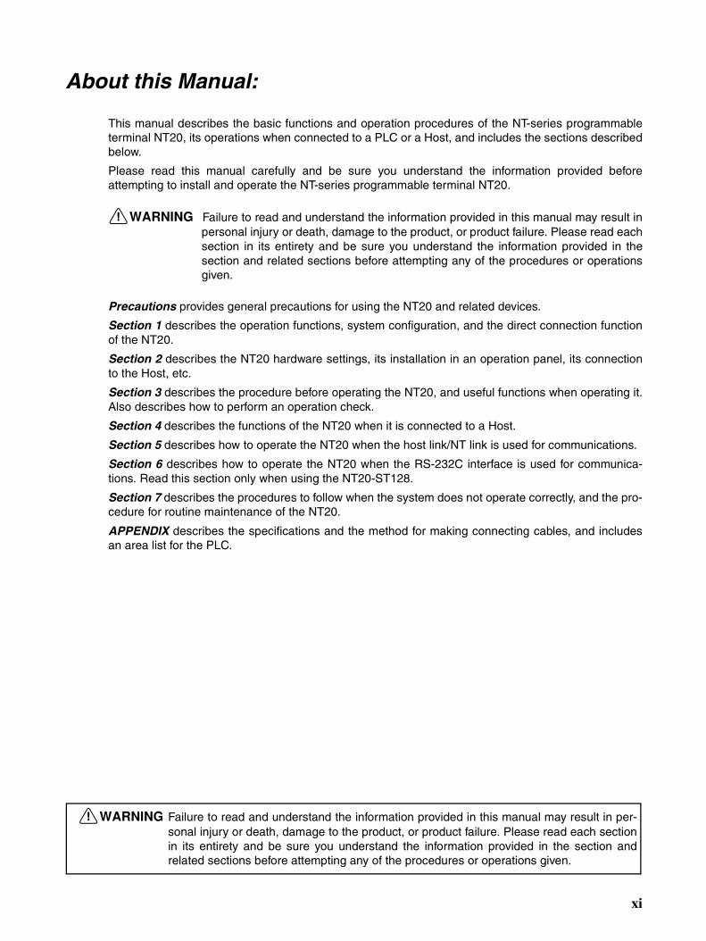
This manual describes the basic functions and operation procedures of the NT-series programmableterminal NT20, its operations when connected to a PLC or a Host, and includes the sections describedbelow.
Please read this manual carefully and be sure you understand the information provided beforeattempting to install and operate the NT-series programmable terminal NT20.
!WARNING Failure to read and understand the information provided in this manual may result inpersonal injury or death, damage to the product, or product failure. Please read eachsection in its entirety and be sure you understand the information provided in thesection and related sections before attempting any of the procedures or operationsgiven.
Precautions provides general precautions for using the NT20 and related devices.
Section 1 describes the operation functions, system configuration, and the direct connection functionof the NT20.
Section 2 describes the NT20 hardware settings, its installation in an operation panel, its connectionto the Host, etc.
Section 3 describes the procedure before operating the NT20, and useful functions when operating it.Also describes how to perform an operation check.
Section 4 describes the functions of the NT20 when it is connected to a Host.
Section 5 describes how to operate the NT20 when the host link/NT link is used for communications.
Section 6 describes how to operate the NT20 when the RS-232C interface is used for communica-tions. Read this section only when using the NT20-ST128.
Section 7 describes the procedures to follow when the system does not operate correctly, and the pro-cedure for routine maintenance of the NT20.
APPENDIX describes the specifications and the method for making connecting cables, and includesan area list for the PLC.
!WARNING Failure to read and understand the information provided in this manual may result in per-sonal injury or death, damage to the product, or product failure. Please read each sectionin its entirety and be sure you understand the information provided in the section andrelated sections before attempting any of the procedures or operations given.
xi
Related Manuals and Their Contents:
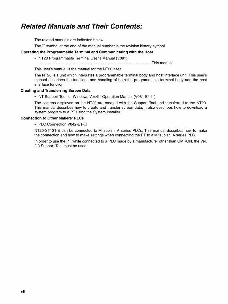
The related manuals are indicated below.
The @ symbol at the end of the manual number is the revision history symbol.
Operating the Programmable Terminal and Communicating with the Host
• NT20 Programmable Terminal User’s Manual (V091) - - - - - - - - - - - - - - - - - - - - - - - - - - - - - - - - - - - - - - - - - - - - - - - - This manual
This user’s manual is the manual for the NT20 itself.
The NT20 is a unit which integrates a programmable terminal body and host interface unit. This user’smanual describes the functions and handling of both the programmable terminal body and the hostinterface function.
Creating and Transferring Screen Data
• NT Support Tool for Windows Ver.4@ Operation Manual (V061-E1-@)
The screens displayed on the NT20 are created with the Support Tool and transferred to the NT20.This manual describes how to create and transfer screen data. It also describes how to download asystem program to a PT using the System Installer.
Connection to Other Makers’ PLCs
• PLC Connection V042-E1-@NT20-ST121-E can be connected to Mitsubishi A series PLCs. This manual describes how to makethe connection and how to make settings when connecting the PT to a Mitsubishi A series PLC.
In order to use the PT while connected to a PLC made by a manufacturer other than OMRON, the Ver.2.3 Support Tool must be used.
xii
Read and Understand this ManualPlease read and understand this manual before using the product. Please consult your OMRON representative if you have any questions or comments.
Warranty and Limitations of Liability
WARRANTY
OMRON's exclusive warranty is that the products are free from defects in materials and workmanship for a period of one year (or other period if specified) from date of sale by OMRON.
OMRON MAKES NO WARRANTY OR REPRESENTATION, EXPRESS OR IMPLIED, REGARDING NON-INFRINGEMENT, MERCHANTABILITY, OR FITNESS FOR PARTICULAR PURPOSE OF THE PRODUCTS. ANY BUYER OR USER ACKNOWLEDGES THAT THE BUYER OR USER ALONE HAS DETERMINED THAT THE PRODUCTS WILL SUITABLY MEET THE REQUIREMENTS OF THEIR INTENDED USE. OMRON DISCLAIMS ALL OTHER WARRANTIES, EXPRESS OR IMPLIED.
LIMITATIONS OF LIABILITY
OMRON SHALL NOT BE RESPONSIBLE FOR SPECIAL, INDIRECT, OR CONSEQUENTIAL DAMAGES, LOSS OF PROFITS OR COMMERCIAL LOSS IN ANY WAY CONNECTED WITH THE PRODUCTS, WHETHER SUCH CLAIM IS BASED ON CONTRACT, WARRANTY, NEGLIGENCE, OR STRICT LIABILITY.
In no event shall the responsibility of OMRON for any act exceed the individual price of the product on which liability is asserted.
IN NO EVENT SHALL OMRON BE RESPONSIBLE FOR WARRANTY, REPAIR, OR OTHER CLAIMS REGARDING THE PRODUCTS UNLESS OMRON'S ANALYSIS CONFIRMS THAT THE PRODUCTS WERE PROPERLY HANDLED, STORED, INSTALLED, AND MAINTAINED AND NOT SUBJECT TO CONTAMINATION, ABUSE, MISUSE, OR INAPPROPRIATE MODIFICATION OR REPAIR.
xiii
Application Considerations
SUITABILITY FOR USE
OMRON shall not be responsible for conformity with any standards, codes, or regulations that apply to the combination of products in the customer's application or use of the products.
At the customer's request, OMRON will provide applicable third party certification documents identifying ratings and limitations of use that apply to the products. This information by itself is not sufficient for a complete determination of the suitability of the products in combination with the end product, machine, system, or other application or use.
The following are some examples of applications for which particular attention must be given. This is not intended to be an exhaustive list of all possible uses of the products, nor is it intended to imply that the uses listed may be suitable for the products:
• Outdoor use, uses involving potential chemical contamination or electrical interference, or conditions or uses not described in this manual.
• Nuclear energy control systems, combustion systems, railroad systems, aviation systems, medical equipment, amusement machines, vehicles, safety equipment, and installations subject to separate industry or government regulations.
• Systems, machines, and equipment that could present a risk to life or property.
Please know and observe all prohibitions of use applicable to the products.
NEVER USE THE PRODUCTS FOR AN APPLICATION INVOLVING SERIOUS RISK TO LIFE OR PROPERTY WITHOUT ENSURING THAT THE SYSTEM AS A WHOLE HAS BEEN DESIGNED TO ADDRESS THE RISKS, AND THAT THE OMRON PRODUCTS ARE PROPERLY RATED AND INSTALLED FOR THE INTENDED USE WITHIN THE OVERALL EQUIPMENT OR SYSTEM.
PROGRAMMABLE PRODUCTS
OMRON shall not be responsible for the user's programming of a programmable product, or any consequence thereof.
xiv
Disclaimers
CHANGE IN SPECIFICATIONS
Product specifications and accessories may be changed at any time based on improvements and other reasons.
It is our practice to change model numbers when published ratings or features are changed, or when significant construction changes are made. However, some specifications of the products may be changed without any notice. When in doubt, special model numbers may be assigned to fix or establish key specifications for your application on your request. Please consult with your OMRON representative at any time to confirm actual specifications of purchased products.
DIMENSIONS AND WEIGHTS
Dimensions and weights are nominal and are not to be used for manufacturing purposes, even when tolerances are shown.
PERFORMANCE DATA
Performance data given in this manual is provided as a guide for the user in determining suitability and does not constitute a warranty. It may represent the result of OMRON's test conditions, and the users must correlate it to actual application requirements. Actual performance is subject to the OMRON Warranty and Limitations of Liability.
ERRORS AND OMISSIONS
The information in this manual has been carefully checked and is believed to be accurate; however, no responsibility is assumed for clerical, typographical, or proofreading errors, or omissions.
xv

xvi
PRECAUTIONS
This section provides general precautions for using the Programmable Terminal.
The information contained in this section is important for the safe and reliable application of the ProgrammableTerminal. You must read this section and understand the information contained before attempting to set up oroperate a Programmable Terminal.
1 Intended Audience . . . . . . . . . . . . . . . . . . . . . . . . . . . . . . . . . . . . . . . . . . . . . xviii2 General Precautions . . . . . . . . . . . . . . . . . . . . . . . . . . . . . . . . . . . . . . . . . . . . xviii3 Safety Precautions. . . . . . . . . . . . . . . . . . . . . . . . . . . . . . . . . . . . . . . . . . . . . . xviii4 Operating Environment Precautions . . . . . . . . . . . . . . . . . . . . . . . . . . . . . . . . xix5 Application Precautions . . . . . . . . . . . . . . . . . . . . . . . . . . . . . . . . . . . . . . . . . xix6 EC Directives . . . . . . . . . . . . . . . . . . . . . . . . . . . . . . . . . . . . . . . . . . . . . . . . . xx
xvii
Intended Audience 1
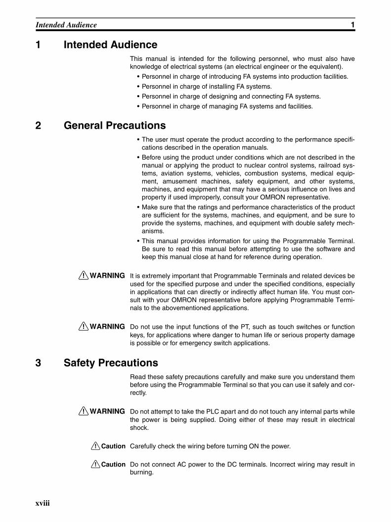
1 Intended AudienceThis manual is intended for the following personnel, who must also haveknowledge of electrical systems (an electrical engineer or the equivalent).
• Personnel in charge of introducing FA systems into production facilities.
• Personnel in charge of installing FA systems.
• Personnel in charge of designing and connecting FA systems.
• Personnel in charge of managing FA systems and facilities.
2 General Precautions• The user must operate the product according to the performance specifi-
cations described in the operation manuals.
• Before using the product under conditions which are not described in themanual or applying the product to nuclear control systems, railroad sys-tems, aviation systems, vehicles, combustion systems, medical equip-ment, amusement machines, safety equipment, and other systems,machines, and equipment that may have a serious influence on lives andproperty if used improperly, consult your OMRON representative.
• Make sure that the ratings and performance characteristics of the productare sufficient for the systems, machines, and equipment, and be sure toprovide the systems, machines, and equipment with double safety mech-anisms.
• This manual provides information for using the Programmable Terminal.Be sure to read this manual before attempting to use the software andkeep this manual close at hand for reference during operation.
!WARNING It is extremely important that Programmable Terminals and related devices beused for the specified purpose and under the specified conditions, especiallyin applications that can directly or indirectly affect human life. You must con-sult with your OMRON representative before applying Programmable Termi-nals to the abovementioned applications.
!WARNING Do not use the input functions of the PT, such as touch switches or functionkeys, for applications where danger to human life or serious property damageis possible or for emergency switch applications.
3 Safety PrecautionsRead these safety precautions carefully and make sure you understand thembefore using the Programmable Terminal so that you can use it safely and cor-rectly.
!WARNING Do not attempt to take the PLC apart and do not touch any internal parts whilethe power is being supplied. Doing either of these may result in electricalshock.
!Caution Carefully check the wiring before turning ON the power.
!Caution Do not connect AC power to the DC terminals. Incorrect wiring may result inburning.
xviii

Operating Environment Precautions 4
!Caution If the DIP switch settings have been changed when the NT20 is powered,reset the power to the NT20. The changes with the DIP switches becomeeffective only after the power supply is reset.
4 Operating Environment Precautions1,2,3... 1. Do not install the PT in any of the following locations.
• Locations subject to rapid changes in temperature
• Locations subject to temperatures or humidity outside the range specifiedin the specifications
• Locations subject to condensation as the result of high humidity
• Locations subject to splashing chemicals or solvents
• Locations subject to oil splashes
• Locations subject to corrosive or flammable gases
• Locations subject to strong shock or vibration
• Locations outdoors subject to direct wind and rain
• Locations subject to strong ultraviolet light
2. Take appropriate and sufficient countermeasures when installing systemsin the following locations.
• Locations subject to static electricity or other forms of noise
• Locations subject to strong electromagnetic or magnetic fields
• Locations close to power supply lines
• Locations subject to possible exposure to radioactivity
5 Application Precautions1,2,3... 1. When unpacking the PT, check carefully for any external scratches or other
damage. Also, shake the PT gently and check for any abnormal sound.
2. Turn OFF the power supply to the PT before mounting or dismounting anyInterface Unit, such as a Memory Unit. Correctly mount the Interface Unitaccording to the NT20 User's Manual.
3. Do not touch PCBs with bare hands. Discharge static electricity accumu-lated in your body in advance.
4. The mounting panel must be between 1.6 and 4.8 mm thick. Tighten theMounting Brackets evenly to a torque of between 0.5 and 0.6 N·m to main-tain water and dust resistance. Make sure the panel is not dirty or warpedand that it is strong enough to hold the PT.
5. Do not let metal particles enter the PT when preparing the panel.
6. Do not perform a dielectric voltage test on the PT.
7. Use a DC power supply that is isolated between DC output and AC input,and has minimal fluctuation voltage.Rated power supply voltage: 24 VDC (Allowable range: 20.4 to 27.6 VDC)Capacity: 10 W min.
8. Use a twisted-pair cable of at least 2 mm2 to connect to the power supplyterminals. Tighten the terminal screws to 0.8 N·m. Make sure the screwsare properly tightened.
9. Turn OFF the power supply to the PT before connecting or disconnectingcables between devices.
xix

EC Directives 6
10. Always tighten the connector screws after connecting communications ca-bles.
11. The maximum pull load for cables is 30 N. Do not apply loads greater thanthis.
12. Confirm that the current capacity of the connected device is 150 mA or lessbefore using the 5-V power supply from pin 6 of serial port A or port B. The5-V output of the NT20 is 150 mA maximum at 5 V ±5%.
13. Confirm the safety of the system before turning ON or OFF the power sup-ply or pressing the reset switch.
14. The whole system may stop depending on how the power supply is turnedON or OFF. Turn ON or OFF the power supply according to the specifiedprocedure.
15. Start actual system application only after sufficiently checking screen dataand the operation of the program in the PLC (host).
16. Do not press any touch switch with a force greater than 30 N.
17. Do not accidentally press touch switches when the Backlight is not lit orwhen the display does not appear. Confirm the safety of the system beforepressing touch switches.
18. Signals from the touch switches may not be input if the switches arepressed consecutively at high speed. Confirm each input before proceed-ing to the next touch switch.
19. To ensure greater safety for numeric inputs, use the upper/lower limit set-ting function.
20. When transferring data in screen units, also transfer any data associatedwith the screen, such as memory tables or direct connection data, if any ofthis data has changed.
21. To assure system safety, incorporate a program that periodically calls PToperation bits from the host side to check that the PT is properly operating.
22. An afterimage will remain if the same patterns are displayed continuouslyfor extended periods of time (e.g., 24 hours). Use the screen saver or pe-riodically change the display to prevent afterimages.
23. Do not use benzene, paint thinner, or other volatile solvents, and do notuse chemically treated cloths.
24. Do not attempt to disassemble, repair, or modify the PT in any way.
25. The backlight in the PT contains mercury. Do not dispose of the PT togeth-er with waste to be processed at disposal plants. Dispose of the PT accord-ing to all local laws, regulations, and ordinances as they apply.
26. Confirm the installation conditions periodically when the PT is being usedin an environment subject to oil or water.
27. Water resistance will be lost if the front sheet is not present. Confirm thatthe front sheet is present before using the PT.
6 EC DirectivesConforming DirectiveThe NT20 PTs conform to the EMC Directive.
xx
EC Directives 6
EMC Directive ConformanceOMRON products are designed as electrical devices for use built into otherdevices or the overall machine. As individual devices, they comply with therelated EMC standards (see note) so that they can more easily be built intoother devices or the overall machine. The actual products have been checkedfor conformity to EMC standards. Whether they conform to the standards inthe system used by the customer, however, must be checked by the customer.
EMC-related performance of the OMRON devices will vary depending on theconfiguration, wiring, and other conditions of the equipment or control panelon which the OMRON devices are installed. The customer must, therefore,perform the final check to confirm that devices and the overall machine con-form to EMC standards.
Note Applicable EMC (Electromagnetic Compatibility) standards are as follows:
EMS (Electromagnetic Susceptibility): EN 61131-2EMI (Electromagnetic Interference): EN 61131-2 (Radiated emission:
10-m regulations)
Complying with EC DirectivesNT-series PTs comply with EC Directives. Observe the following precautionsto ensure that the customer’s device and the overall machine also comply withEC Directives.
1,2,3... 1. The PT is designed for installation inside a control panel. The PT must beinstalled within a control panel.
2. Use reinforced insulation or double insulation for the DC power supply tothe PT. Ensure that a stable power output can be provided even if a 10-msinterruption occurs at the input.
3. The PT conforms to the EN 61131-2, but the radiated emission character-istics (10-m regulations) may vary depending on the configuration of thecontrol panel used, other devices connected to the control panel, wiring,and other conditions. You must therefore confirm that the overall machineor equipment complies with EC Directives.
xxi

EC Directives 6
xxii

SECTION 1Functions of the NT20
NT20 is a new programmable terminal (PT) which incorporates a host interface unit and two RS-232C interface units in aprogrammable terminal body. It can be easily installed and used. This section gives the operation examples andcharacteristics of the NT20 so that you will understand the applications of the NT20.
1-1 Role and Operation of NT20. . . . . . . . . . . . . . . . . . . . . . . . . . . . . . . . . . . . . . 2
1-1-1 Operations of NT20 . . . . . . . . . . . . . . . . . . . . . . . . . . . . . . . . . . . . . 3
1-2 Functions of NT20 . . . . . . . . . . . . . . . . . . . . . . . . . . . . . . . . . . . . . . . . . . . . . 4
1-2-1 Features. . . . . . . . . . . . . . . . . . . . . . . . . . . . . . . . . . . . . . . . . . . . . . . 4
1-2-2 Principal Functions of NT20 . . . . . . . . . . . . . . . . . . . . . . . . . . . . . . 5
1-2-3 Comparison between NT20S, NT20M, and NT20. . . . . . . . . . . . . . 6
1-2-4 Displays . . . . . . . . . . . . . . . . . . . . . . . . . . . . . . . . . . . . . . . . . . . . . . 7
1-3 Method for Connection to the Host. . . . . . . . . . . . . . . . . . . . . . . . . . . . . . . . . 8
1-4 Communications with PLC by Direct Connection . . . . . . . . . . . . . . . . . . . . . 10
1-4-1 Functions of the Allocated Bits and Words . . . . . . . . . . . . . . . . . . . 10
1-4-2 Connecting to PLC from Other Companies . . . . . . . . . . . . . . . . . . . 12
1-5 Communications Using RS-232C (NT20-ST128) . . . . . . . . . . . . . . . . . . . . . 13
1-6 Before Operating. . . . . . . . . . . . . . . . . . . . . . . . . . . . . . . . . . . . . . . . . . . . . . . 14
1
Role and Operation of NT20 Section 1-1
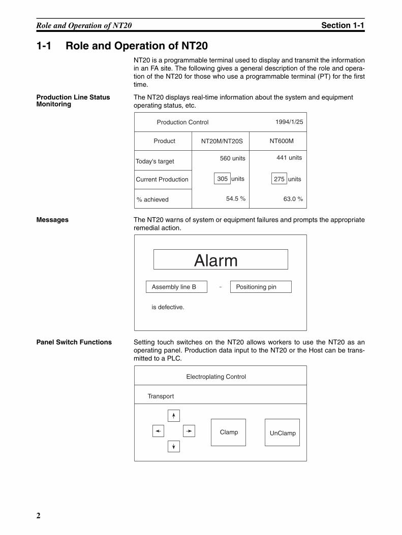
1-1 Role and Operation of NT20NT20 is a programmable terminal used to display and transmit the informationin an FA site. The following gives a general description of the role and opera-tion of the NT20 for those who use a programmable terminal (PT) for the firsttime.
Production Line Status Monitoring
The NT20 displays real-time information about the system and equipmentoperating status, etc.
Messages The NT20 warns of system or equipment failures and prompts the appropriateremedial action.
Panel Switch Functions Setting touch switches on the NT20 allows workers to use the NT20 as anoperating panel. Production data input to the NT20 or the Host can be trans-mitted to a PLC.
Production Control 1994/1/25
Today's target
NT20M/NT20S NT600M
54.5 %
441 units
Product
Current Production
% achieved
305 units
560 units
275 units
63.0 %
-Assembly line B
is defective.
AlarmPositioning pin
Electroplating Control
Transport
Clamp UnClamp
2

Role and Operation of NT20 Section 1-1
1-1-1 Operations of NT20Displays Screens The information to be displayed (screen data) can be created on a computer
by using the Support Tool and stored in the NT20. The screen data can bedisplayed on the NT20 in response to the instructions from a Host or touchswitch operation.
Receives Data from a Host The NT20 can be connected to the Host using the host link or NT link commu-nications method to enable reception of the required data from the Host.
Sends Data to a Host Data input through a touch panel can be sent to a Host.
Screen Data The screen data to be displayed on the NT20 can be created by a computerby using the Support Tool. Connect the NT20 to a PC/AT with an RS-232Ccable so that the screen data are transferred to the NT20.
Host
The screen data designated by instructions from Host or touch switch operation is displayed.
Host
Host link, NT link, RS-232C, C200H direct communications
Host
ON/OFF information, numeric data, etc.
Touch panel
Create screen data.
PC/AT(Support Tool)
Screen data
RS-232C
When the host is connected at serial port A, the personal computer is connected only when transferring screen data between the NT20 and NT Support Tool.
3

Functions of NT20 Section 1-2
1-2 Functions of NT20The NT20 has the following features which are different from those of existingNT20M/NT20S;
1-2-1 FeaturesDownsized Body • The connectors are located at other than the front.
• The communications cable connectors are housed in the unit so that theydo not protrude from the unit.
• The tool connectors and the Host communications connectors are used incommon (when the host link/NT link is used).
Construction Best Suited to the FA Environment• Easy-to-read screen even in direct sunlight.
• Long-lived backlight leads free from maintenance.
• Waterproof structure equivalent to oil-resistant IP65.
A Host Link I/F Unit, Screen Data Memory, and a System ROM Are All Incorporated• With the NT link communications method, 1:1 connections and 1:N con-
nections are possible.
• There is no complicated installation work except a simple connection to aHost.
• A flash memory is used for the screen data memory. There is no need ofbackup battery.
• The following communications methods are standard for each model:NT20-ST121-E: Host Link (direct) and NT LinkNT20-ST121-E + NT20-IF001 + NT600M-LB122-V1: C200H direct com-municationsNT20-ST128: RS-232C communications (command control)
• The NT20 can be connected to Mitsubishi FX-series and Mitsubishi A-series PLCs. (Refer to PLC Connection, Operation Manual (Cat. No.V042-E1-@)).
Touch Switch Operation The System Menu can be displayed by using the touch switches located infour corners of the screen.
Compatibility with NT20M/NT20S
Existing screen data, user programs, are compatible.
Wide angle of visibility ±35°
128 dots
256 dots
4
Functions of NT20 Section 1-2
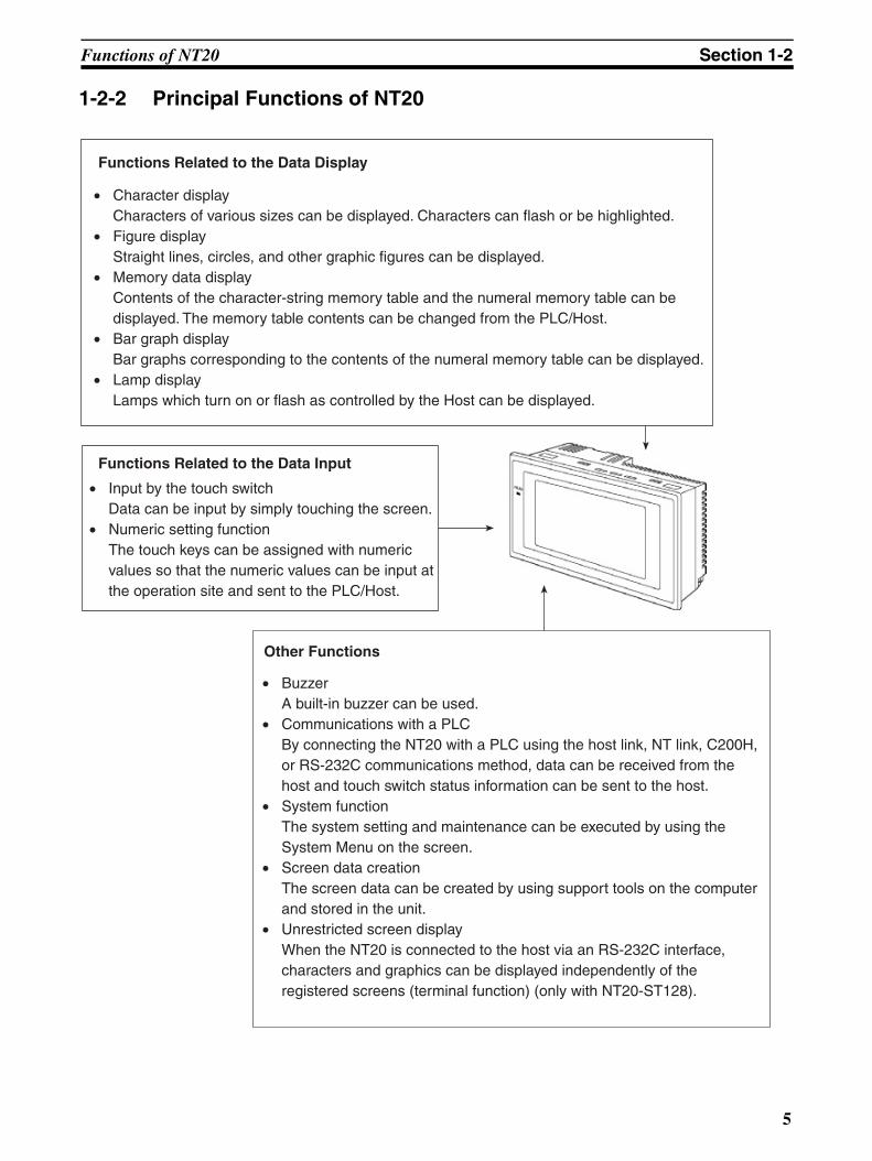
1-2-2 Principal Functions of NT20
Functions Related to the Data Display
Other Functions
Functions Related to the Data Input
• Character display Characters of various sizes can be displayed. Characters can flash or be highlighted.
• Figure display Straight lines, circles, and other graphic figures can be displayed.
• Memory data display Contents of the character-string memory table and the numeral memory table can be displayed. The memory table contents can be changed from the PLC/Host.
• Bar graph display Bar graphs corresponding to the contents of the numeral memory table can be displayed.
• Lamp display Lamps which turn on or flash as controlled by the Host can be displayed.
• Input by the touch switch Data can be input by simply touching the screen.
• Numeric setting function The touch keys can be assigned with numeric values so that the numeric values can be input at the operation site and sent to the PLC/Host.
• Buzzer A built-in buzzer can be used.
• Communications with a PLC By connecting the NT20 with a PLC using the host link, NT link, C200H, or RS-232C communications method, data can be received from the host and touch switch status information can be sent to the host.
• System function The system setting and maintenance can be executed by using the System Menu on the screen.
• Screen data creation The screen data can be created by using support tools on the computer and stored in the unit.
• Unrestricted screen display When the NT20 is connected to the host via an RS-232C interface, characters and graphics can be displayed independently of the registered screens (terminal function) (only with NT20-ST128).
5
Functions of NT20 Section 1-2
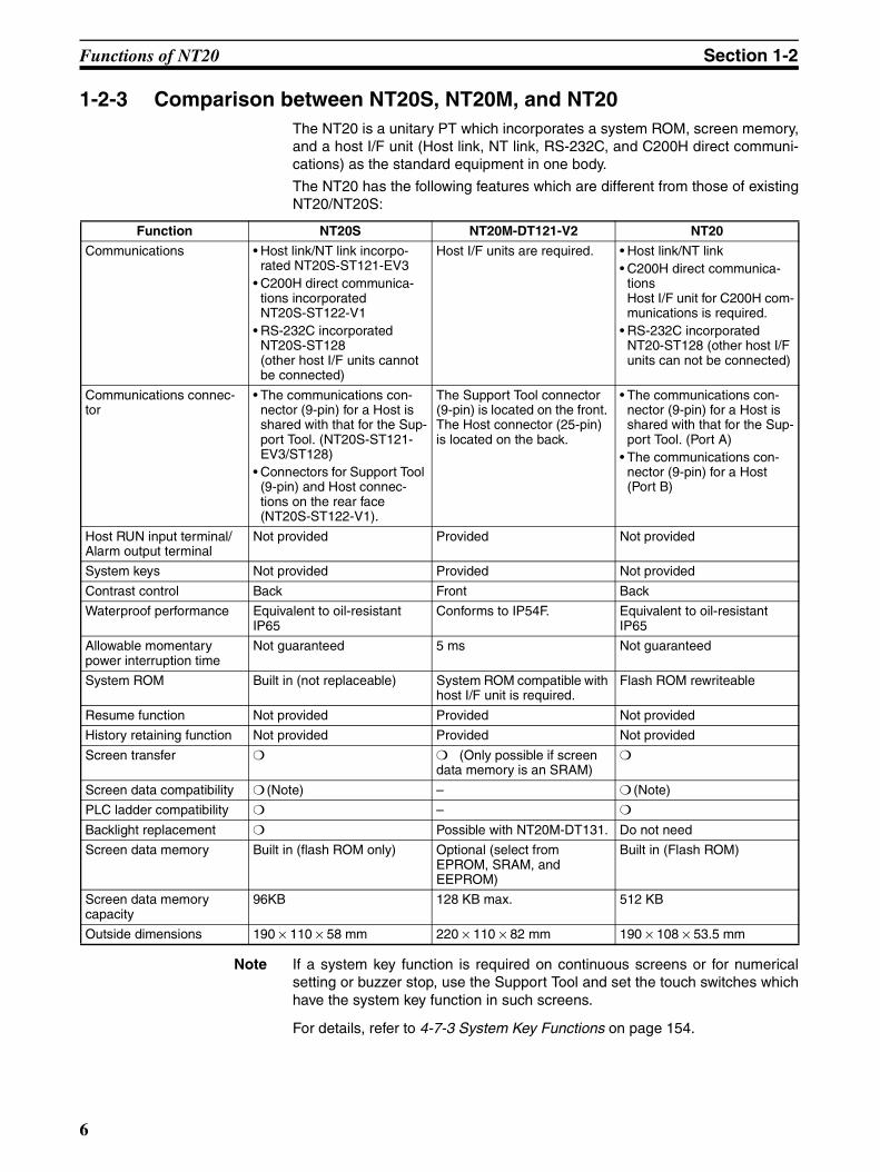
1-2-3 Comparison between NT20S, NT20M, and NT20The NT20 is a unitary PT which incorporates a system ROM, screen memory,and a host I/F unit (Host link, NT link, RS-232C, and C200H direct communi-cations) as the standard equipment in one body.
The NT20 has the following features which are different from those of existingNT20/NT20S:
Note If a system key function is required on continuous screens or for numericalsetting or buzzer stop, use the Support Tool and set the touch switches whichhave the system key function in such screens.
For details, refer to 4-7-3 System Key Functions on page 154.
Function NT20S NT20M-DT121-V2 NT20
Communications • Host link/NT link incorpo-rated NT20S-ST121-EV3
• C200H direct communica-tions incorporatedNT20S-ST122-V1
• RS-232C incorporated NT20S-ST128(other host I/F units cannot be connected)
Host I/F units are required. • Host link/NT link • C200H direct communica-
tions Host I/F unit for C200H com-munications is required.
• RS-232C incorporated NT20-ST128 (other host I/F units can not be connected)
Communications connec-tor
• The communications con-nector (9-pin) for a Host is shared with that for the Sup-port Tool. (NT20S-ST121-EV3/ST128)
• Connectors for Support Tool (9-pin) and Host connec-tions on the rear face (NT20S-ST122-V1).
The Support Tool connector (9-pin) is located on the front. The Host connector (25-pin) is located on the back.
• The communications con-nector (9-pin) for a Host is shared with that for the Sup-port Tool. (Port A)
• The communications con-nector (9-pin) for a Host (Port B)
Host RUN input terminal/Alarm output terminal
Not provided Provided Not provided
System keys Not provided Provided Not provided
Contrast control Back Front Back
Waterproof performance Equivalent to oil-resistant IP65
Conforms to IP54F. Equivalent to oil-resistant IP65
Allowable momentary power interruption time
Not guaranteed 5 ms Not guaranteed
System ROM Built in (not replaceable) System ROM compatible with host I/F unit is required.
Flash ROM rewriteable
Resume function Not provided Provided Not provided
History retaining function Not provided Provided Not provided
Screen transfer (Only possible if screen data memory is an SRAM)
Screen data compatibility (Note) – (Note)
PLC ladder compatibility –
Backlight replacement Possible with NT20M-DT131. Do not need
Screen data memory Built in (flash ROM only) Optional (select from EPROM, SRAM, and EEPROM)
Built in (Flash ROM)
Screen data memorycapacity
96KB 128 KB max. 512 KB
Outside dimensions 190 × 110 × 58 mm 220 × 110 × 82 mm 190 × 108 × 53.5 mm
6
Functions of NT20 Section 1-2
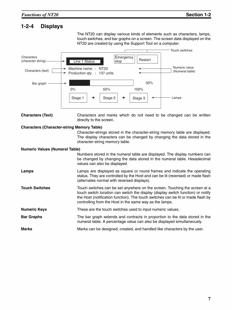
1-2-4 DisplaysThe NT20 can display various kinds of elements such as characters, lamps,touch switches, and bar graphs on a screen. The screen data displayed on theNT20 are created by using the Support Tool on a computer.
Characters (Text) Characters and marks which do not need to be changed can be writtendirectly to the screen.
Characters (Character-string Memory Table)Character-strings stored in the character-string memory table are displayed.The display characters can be changed by changing the data stored in thecharacter-string memory table.
Numeric Values (Numeral Table)Numbers stored in the numeral table are displayed. The display numbers canbe changed by changing the data stored in the numeral table. Hexadecimalvalues can also be displayed.
Lamps Lamps are displayed as square or round frames and indicate the operatingstatus. They are controlled by the Host and can be lit (reversed) or made flash(alternates normal with reversed displays).
Touch Switches Touch switches can be set anywhere on the screen. Touching the screen at atouch switch location can switch the display (display switch function) or notifythe Host (notification function). The touch switches can be lit or made flash bycontrolling from the Host in the same way as the lamps.
Numeric Keys These are the touch switches used to input numeric values.
Bar Graphs The bar graph extends and contracts in proportion to the data stored in thenumeral table. A percentage value can also be displayed simultaneously.
Marks Marks can be designed, created, and handled like characters by the user.
Line 1 Status Restart
Machine name : NT20Production qty. : 137 units
0% 50% 100%
30%
Stage 1 Stage 2 Stage 3 Lamps
Touch switches
Characters (text)
Bar graph
Emergency stop
Characters (character string)
Numeric value (Numeral table)
7

Method for Connection to the Host Section 1-3
1-3 Method for Connection to the HostThis section describes the methods for connection to the host used with theNT20, and the relationship between the connection method and the communi-cations method.
NT20 Communications Ports and Communications Methods
The NT20 has two communications ports. Their uses are indicated in thetable below.
Note There are two 1:N NT Link communications rates: standard and high-speed.
Converting Communications Type with the RS-232C/RS-422A Link Adapter and RS-422A Converter
An OMRON NT-AL001 Link Adapter or CJ1W-CIF11 RS-422A Converter canbe used convert from RS-232C communications to either RS-422A or RS-485.
• RS-232C ⇔ RS-422A
• RS-232C ⇔ RS-485There are two models of Link Adapter/RS-422A Converter are available. Theyprovide different features:
• NT-AL001 Link AdapterThe RS-232C port is insulated from the RS-422A/485 terminals. An RS-232C cable (2 m max.) can be connected to either serial port A or B onthe NT20.
• CJ1W-CIF11 RS-422A ConverterThe RS-232C port is not insulated from the RS-422A/485 terminals. TheCJ1W-CIF11 RS-422A Converter can be connected to either serial port Aor B on the NT20.
• Communications DistanceUse the NT-AL001 if the communications distance exceeds 50 m.
Communications Port
Usable Communications Methods
Communications
Serial port A Host Link1:1 NT Link
1:N NT Link (See note.)RS-232C (command control) (NT-20-ST128)
(NT Support Tool connection)
RS-232C
Serial port B Host Link
1:1 NT Link1:N NT Link (See note.)RS-232C (command control) (NT-20-ST128)
RS-232C
8

Method for Connection to the Host Section 1-3
Combinations of Communications Method and Connection Method
The connection methods that can be used depending on the communicationsmethod used and the communications type for communications between theNT20 and the host are indicated in the table below.
: Connection possible ×: Connection not possible
Note (1) An RS-232C Cable (not shown in the diagram) is required when connect-ing an NT-AL001 Link Adapter to a PT.
(2) If the CJ1W-CIF11 is used, the total communications distance is 50 m.This also applies if both the NT-AL001 and CJ1W-CIF11 are used in thesame communications path.
Communications type at Host
Usable Connection Method Usable Communications Method
Host Link 1:1 NT Link 1:N NT Link
RS-232C
RS-232C × ×
RS-232C × ×
Direct 1:1 connectionPT Host
RS-232C (15 m max.)
1:N connection with RS-422A through Link Adapter and RS-422A Converters
PT Host
NT-AL001 (See note 1.) or CJ1W-CIF11 RS-422A Converter NT-AL001
Link Adapter
RS-422A (total length 500 m, See note 2.)
RS-232C (2 m max.)
1:N connection with RS-485 through Link Adapter and RS-422A Converters
PT HostNT-AL001 (See note 1.) or CJ1W-CIF11 RS-422A Converter NT-AL001
Link Adapter
RS-485 (total length 500 m, See note 2.)
RS-232C (2 m max.)
9
Communications with PLC by Direct Connection Section 1-4
1-4 Communications with PLC by Direct Connection
1-4-1 Functions of the Allocated Bits and WordsWhen using an NT20-ST121@ with the direct connection function (host link orNT link), the elements displayed on the NT20 and the NT20 status can beallocated to the bits and words of the PLC. By changing the contents of thebits and words, the NT20 can be controlled by the PLC. It is also possible tosend data to the PLC by pressing the touch switches on the NT20.
• Controlling the NT20 by a PLC
The following NT20 functions can be controlled by a PLC.
Screens: Display of designated screens, confirmationof screen numbers, etc.
Memory tables: Writing to a memory table, copying from amemory table entry to another memory tableentry, etc.
Lamps and touch switches: Display instructions, confirmation of displaystatus, etc.
System control: Buzzer ON/OFF, backlight ON/OFF, and oth-er NT20 status
• Notifying the PLC from the NT20
Data in the NT20 is sent to a PLC when a touch switch is pressed. The fol-lowing types of data are sent to a PLC.
• NT20 status
• Touch switch status
• Numerical values input with touch switches by using the numeral set-ting function
• Changes in a memory table after copying between memory table en-tries
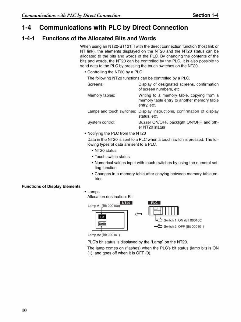
Functions of Display Elements• Lamps
Allocation destination: Bit
PLC’s bit status is displayed by the “Lamp” on the NT20.
The lamp comes on (flashes) when the PLC’s bit status (lamp bit) is ON(1), and goes off when it is OFF (0).
Lamp #1 (Bit 000100)
Lamp #2 (Bit 000101)
Switch 1: ON (Bit 000100)
Switch 2: OFF (Bit 000101)
NT20 PLC
Lit
Unlit
10
Communications with PLC by Direct Connection Section 1-4
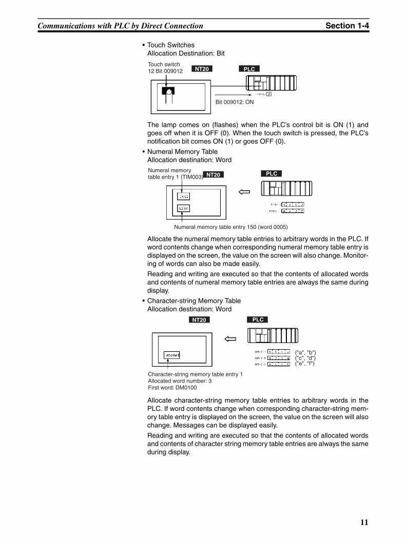
• Touch SwitchesAllocation Destination: Bit
The lamp comes on (flashes) when the PLC’s control bit is ON (1) andgoes off when it is OFF (0). When the touch switch is pressed, the PLC’snotification bit comes ON (1) or goes OFF (0).
• Numeral Memory TableAllocation destination: Word
Allocate the numeral memory table entries to arbitrary words in the PLC. Ifword contents change when corresponding numeral memory table entry isdisplayed on the screen, the value on the screen will also change. Monitor-ing of words can also be made easily.
Reading and writing are executed so that the contents of allocated wordsand contents of numeral memory table entries are always the same duringdisplay.
• Character-string Memory TableAllocation destination: Word
Allocate character-string memory table entries to arbitrary words in thePLC. If word contents change when corresponding character-string mem-ory table entry is displayed on the screen, the value on the screen will alsochange. Messages can be displayed easily.
Reading and writing are executed so that the contents of allocated wordsand contents of character string memory table entries are always the sameduring display.
Bit 009012: ON
NT20 PLCTouch switch 12 Bit 009012
Numeral memory table entry 150 (word 0005)
NT20 PLCNumeral memory table entry 1 (TIM003)
NT20 PLC
("a", "b")("c", "d")("e", "f")
Character-string memory table entry 1 Allocated word number: 3First word: DM0100
11
Communications with PLC by Direct Connection Section 1-4
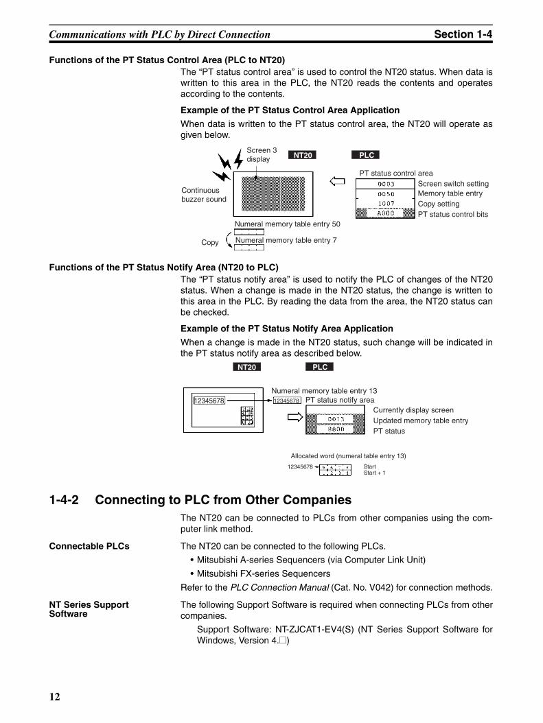
Functions of the PT Status Control Area (PLC to NT20)The “PT status control area” is used to control the NT20 status. When data iswritten to this area in the PLC, the NT20 reads the contents and operatesaccording to the contents.
Example of the PT Status Control Area Application
When data is written to the PT status control area, the NT20 will operate asgiven below.
Functions of the PT Status Notify Area (NT20 to PLC)The “PT status notify area” is used to notify the PLC of changes of the NT20status. When a change is made in the NT20 status, the change is written tothis area in the PLC. By reading the data from the area, the NT20 status canbe checked.
Example of the PT Status Notify Area Application
When a change is made in the NT20 status, such change will be indicated inthe PT status notify area as described below.
1-4-2 Connecting to PLC from Other CompaniesThe NT20 can be connected to PLCs from other companies using the com-puter link method.
Connectable PLCs The NT20 can be connected to the following PLCs.
• Mitsubishi A-series Sequencers (via Computer Link Unit)
• Mitsubishi FX-series Sequencers
Refer to the PLC Connection Manual (Cat. No. V042) for connection methods.
NT Series Support Software
The following Support Software is required when connecting PLCs from othercompanies.
Support Software: NT-ZJCAT1-EV4(S) (NT Series Support Software forWindows, Version 4.@)
Copy
Numeral memory table entry 50
Numeral memory table entry 7
PT status control areaScreen switch settingMemory table entryCopy settingPT status control bits
NT20 PLCScreen 3 display
Continuous buzzer sound
Numeral memory table entry 13PT status notify area
Updated memory table entry
Allocated word (numeral table entry 13)
PT status
StartStart + 1
NT20 PLC
1234567812345678
12345678
Currently display screen
12
Communications Using RS-232C (NT20-ST128) Section 1-5
1-5 Communications Using RS-232C (NT20-ST128)This section gives a brief description of the NT20 control commands sent fromthe host through the RS-232C interface when the NT20-ST128 is used.
For details on each of the commands sent through the RS-232C interface,refer toSECTION 6 Using RS-232C Communications.
Control of the NT20 by a Host is executed by two kinds of commands sup-ported by the RS-232C interface that is built into the NT20.
Operation Commands Operation commands are used to control the display and status of the runningNT20 as well as to provide notification.
They are used for purposes such as screen display, data writing, and enqui-ries.
Notification of the NT20 operation contents can be provided to the Host.
Terminal Commands Terminal commands are used to use the NT20 as a display terminal of theHost.
When the NT20 is used as a display terminal, it can display characters andfigures according to instructions given by the Host, independently of thescreens registered to the NT20.
These commands are also used if unexpected problems occur.
13

Before Operating Section 1-6
1-6 Before OperatingFollow the procedure given below to start the system of the NT20.
Note System program installation is only done in special circumstances, for exam-ple when changing the system program, or when recovering the original sta-tus of the installed program. This operation is not normally necessary.
Host
Set the host settings.
Connect to the NT20.
Create the host program.
Start operation.
NT20
Install the system program.
Transmit the screen data.
Set the memory switches.
Connect to the host.
NT Support Tool
Create the screens.
Install the PT in the operation panel.
Connect the power supply and peripheral device.
(See note.)
Confirm the settings and check communications.
Install the NT Support Tool in the computer.
(Refer to the NT Support Tool Operation Manual.)
(Refer to the NT Support Tool Operation Manual.)
Set the DIP switch pins.
• For the Host Link, refer to page 44, and the man-uals for the Host Link Unit and Programming Device.
• For a 1:1 NT Link, refer to page 56.
• For 1:N NT Links, refer to page 60.
• For high-speed 1:N NT Links, refer to page 65.
• When using C200H direct communications, no settings are required.
• For RS-232C, refer to page 79 and the manu-als for the Host.
(page 22)
(page 23)
(Refer to page 126 and the NT Support Tool operation manual.)
(page 91)
(page 102)
(page 19)
14

Before Operating Section 1-6
Refer to the following manuals for the equipment and software.
Device or Software Manual Title Cat. No.
NT20 User’s Manual V091-E1-@System Installer NT-series Support Tool for Windows (Ver. 4.8) Operation Manual V061-E1-@NT Support Tool NT-series Support Tool for Windows (Ver. 4.8) Operation Manual V061-E1-@PLC SYSMAC CPM1 Operation Manual W262-E1-@
SYSMAC CPM1A Operation Manual W317-E1-@SYSMAC CPM2A Operation Manual W352-E1-@SYSMAC CPM2C Operation Manual W356-E1-@SYSMAC C200H Operation Manual (for CPU01/03/11) (Programming) W130-E1-@SYSMAC C200H Operation Manual (for CPU21/23/31) (Programming) W217-E1-@SYSMAC C200HS Installation Guide W236-E1-@SYSMAC C200HS Operation Manual (Programming) W235-E1-@SYSMAC C200HX/HG/HE (-Z) Installation Guide W302-E1-@SYSMAC C200HX/HG/HE Operation Manual W303-E1-@SYSMAC C200HX/HG/HE-Z Operation Manual W322-E1-@SYSMAC CQM1/CPM1/CPM1A/SRM1 Programming Manual W228-E1-@SYSMAC CQM1H Operation Manual W363-E1-@SYSMAC CVM1/CV500/CV1000/CV2000/CVM1 Operation Manual: Ladder Dia-grams
W202-E1-@
CS Series Programmable Controllers Operation Manual W339-E1-@CJ Series CJ1G-CPU@@-E Programmable Controllers Operation Manual W393-E1-@CS/CJ Series Programming Manual W394-E1-@CS/CJ Series Serial Communications Boards/Units Operation Manual W336-E1-@SYSMAC CQM1H Series Serial Communications Board Operation Manual W365-E1-@
CompoBus Master Control Unit
SRM1 (-V2) Operation Manual W318-E1-@
Programming Tools SYSMAC Support Software Operation Manual: C-series PLCs W248-E1-@SYSMAC Support Software Operation Manual: CVM1 PLCs W249-E1-@SYSMAC CPT User Manual and Quick Start Guide W332-E1-@
W333-E1-@CX-Programmer Ver. 4 User Manual W425-E1-@
Host Link Unit/Serial Communica-tions Board
SYSMAC C Series Host Link Unit System Manual W143-E1-@SYSMAC CVM1/CV Series Host Link Operation Manual W205-E1-@SYSMAC C200HW-COM01 C200HW-COM02-V1 to C200HW-COM06-EV1 Com-munications Board Operation Manual
W304-E1-@
15

Before Operating Section 1-6
16
SECTION 2Hardware Settings and Connections
This section describes the settings of the NT20, connections to a Host, and other hardware settings.
2-1 Description of Parts and Settings . . . . . . . . . . . . . . . . . . . . . . . . . . . . . . . . . . 18
2-1-1 Description of Parts . . . . . . . . . . . . . . . . . . . . . . . . . . . . . . . . . . . . . 18
2-1-2 Operation Status DIP Switch Settings . . . . . . . . . . . . . . . . . . . . . . . 19
2-2 Installation. . . . . . . . . . . . . . . . . . . . . . . . . . . . . . . . . . . . . . . . . . . . . . . . . . . . 21
2-2-1 Installation Environment. . . . . . . . . . . . . . . . . . . . . . . . . . . . . . . . . . 21
2-2-2 Installation to the Operation Panel . . . . . . . . . . . . . . . . . . . . . . . . . . 22
2-2-3 Power Supply Connection . . . . . . . . . . . . . . . . . . . . . . . . . . . . . . . . 23
2-3 Connecting Link Adapters and RS-422A Converters . . . . . . . . . . . . . . . . . . . 24
2-3-1 Connecting an CJ1W-CIF11 RS-422A Converter . . . . . . . . . . . . . . 24
2-3-2 Connecting an NT-AL001 Link Adapter . . . . . . . . . . . . . . . . . . . . . 28
2-4 Connecting the NT Support Tool . . . . . . . . . . . . . . . . . . . . . . . . . . . . . . . . . . 35
2-5 Using a Memory Unit . . . . . . . . . . . . . . . . . . . . . . . . . . . . . . . . . . . . . . . . . . . 36
2-5-1 Installation Method. . . . . . . . . . . . . . . . . . . . . . . . . . . . . . . . . . . . . . 37
2-5-2 Method of Use . . . . . . . . . . . . . . . . . . . . . . . . . . . . . . . . . . . . . . . . . 37
2-6 Connecting to the RS-232C Port at the Host . . . . . . . . . . . . . . . . . . . . . . . . . 44
2-6-1 Host Types and Settings . . . . . . . . . . . . . . . . . . . . . . . . . . . . . . . . . . 44
2-6-2 Connecting Directly between RS-232C Ports . . . . . . . . . . . . . . . . . 69
2-7 Communicating with the PLC Using C200H Direct Communications . . . . . 73
2-7-1 Applicable PLC Units. . . . . . . . . . . . . . . . . . . . . . . . . . . . . . . . . . . . 73
2-7-2 Connection Method . . . . . . . . . . . . . . . . . . . . . . . . . . . . . . . . . . . . . 73
2-7-3 Turning the Power ON/OFF When Using C200H Direct Communications . . . . . . . . . . . . . . . . . . . . . . . . . . . . . . . . . . . . . . . . 77
2-8 Host Connections by RS-232C (NT20-ST128) . . . . . . . . . . . . . . . . . . . . . . . 79
2-8-1 Host Computer Communications Settings . . . . . . . . . . . . . . . . . . . . 79
2-8-2 Connector Pin Arrangement . . . . . . . . . . . . . . . . . . . . . . . . . . . . . . . 79
17
Description of Parts and Settings Section 2-1
Note On unpacking the NT20 and peripheral devices, check their external appear-ance and confirm that there is no damage. Also confirm that there is no abnor-mal noise when you shake the PT lightly.
2-1 Description of Parts and SettingsBefore getting to the operation, confirm the names and functions of parts.Also set the DIP switches on the NT20.
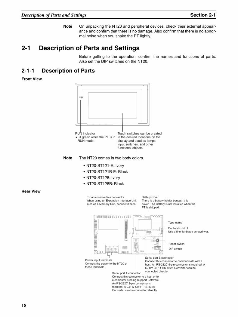
2-1-1 Description of PartsFront View
Note The NT20 comes in two body colors.
• NT20-ST121-E: Ivory
• NT20-ST121B-E: Black
• NT20-ST128: Ivory
• NT20-ST128B: Black
Rear View
RUN indicator• Lit green while the PT is in
RUN mode.
Touch switches can be created in the desired locations on the display and used as lamps, input switches, and other functional objects.
Expansion interface connectorWhen using an Expansion Interface Unit such as a Memory Unit, connect it here.
Battery coverThere is a battery holder beneath this cover. The Battery is not installed when the PT is shipped.
Type name
Power input terminals Connect the power to the NT20 at these terminals
Serial port A connectorConnect this connector to a host or to a computer running Support Software. An RS-232C 9-pin connector is required. A CJ1W-CIF11 RS-422A Converter can be connected directly.
Serial port B connector Connect this connector to communicate with a host. An RS-232C 9-pin connector is required. A CJ1W-CIF11 RS-422A Converter can be connected directly.
Reset switch
DIP switch
Contrast controlUse a fine flat-blade screwdriver.
18

Description of Parts and Settings Section 2-1
2-1-2 Operation Status DIP Switch SettingsSet the NT20 operation status with the DIP switches located in the bottomright corner on the rear of the body.
[ ] indicates factory setting.
!Caution If the DIP switch settings have been changed when the NT20 is powered,reset the power to the NT20. The changes with the DIP switches becomeeffective only after the power supply is reset.
Note (1) ln addition to the DIP switches, set also the “communications type”, “hostlink baud rate”, etc. at the memory switches when host link/NT link isused.For these settings, refer to Section 3-5 Setting the Conditions of Commu-nications with the Host by Using the Memory Switches (page 91).
(2) It may be necessary to change the DIP switch settings after installing theNT20 in an operation panel. Bear this in mind when deciding the installa-
Switch # Function
SW2-1 Screen data forced initialize effective/ineffective
Note When this switch is ON, SW2-4, SW2-5 and SW2-6 must be OFF.
ON The NT20 will start in a special RUN mode in which the screen data memory is initialized. When it is started, the memory initialization menu will be displayed. For the initialization procedure, refer to Section 3-4 Initializing Memory.
[OFF] The NT20 will start in normal RUN mode.
SW2-2 Screen display language mode. DIP SW2-2 is used to indicate language selection. If it is turned ON, then dis-play language will use English and the language parameter in memory SW is not selectable (User can't choose other language than English.) But if it is turned OFF, then user can choose other language through language parameter in memory SW.
[ON] Messages are displayed in English.
OFF Language can be selected.
SW2-3 Switching to the System Menu enabled/disabled
ON The System Menu cannot be displayed. If an error occurs during a start-up, the System Menu will be automatically displayed. However, “transfer mode” cannot be entered.
[OFF] The System Menu can be displayed.
SW2-4 Unused (Reserved for system use)
SW2-5 System resource initialize
Note When this switch is ON, SW2-1, SW2-4 and SW2-6 must be OFF.
ON Effective
[OFF] Invalid
SW2-6 System program initialize
Note When this switch is ON, SW2-1, SW2-4 and SW2-5 must be OFF.
ON Effective
[OFF] Invalid
19

Description of Parts and Settings Section 2-1
tion position.During work at the panel, take care to ensure that no metal scraps enterthe unit.
20
Installation Section 2-2
2-2 InstallationInstall the NT20 to the operation panel and connect the power to the NT20 asdescribed below.
2-2-1 Installation EnvironmentObserve the following points when installing the PT in an operation panel.
!Caution Do not install the NT20 at sites subject to the following conditions.Otherwise, the product may malfunction.
• Severe temperature variations
• Temperatures or humidities outside the ranges stated in the specifications
• High humidity, condensation
• Splashing chemical agents
• Severe oil splashing
• Corrosive or flammable gases
• Strong vibrations or shocks
• Direct exposure to wind and rain (outdoor sites)
• Strong ultra-violet irradiation
Take adequate measures to ensure shielding if the NT20 is used at a locationsubject to any of the following conditions.
• Static electricity, or noise from other equipment
• Strong electric or magnetic fields
• Nearby power cables
• Potential exposure to radioactivity
!Caution Do not perform a withstand voltage test. Performing with stand voltage testsmay result in malfunction.
21

Installation Section 2-2
2-2-2 Installation to the Operation PanelThe NT20 can be flush mounted to an operation panel.
Use the panel fittings and tools included in the product package and follow theprocedure below.
!Caution During work at the panel, take care to ensure that no metal scraps enter theunit. Otherwise, the product may malfunction.
Note The thickness of applicable operation panel is 1.6 mm to 4.8 mm. All fittingsmust be tightened uniformly to a torque of at least 0.5 to 0.6 N·cm in order toensure water- and dust-resistance. The panel must not be soiled or warped,and must be able to support an installation that will remain secure and strong.
1. Open a hole, shown below, in the panel and install the NT20 from the frontof the panel.
2. Attach the panel fittings at four positions, shown below, on the rear of theNT20.
Fit the hook of the fitting in the square hole in the body and tighten thescrew with a Phillips head screwdriver while lightly pulling the fitting.
Note In order to ensure adequate water and dustproof performance, tighten the fourpanel fittings uniformly and make sure there are no gaps between the fittingsand the NT20 panel.
98.5
178.5 +0.5 mm0 mm
+0.5 mm0 mm
22
Installation Section 2-2
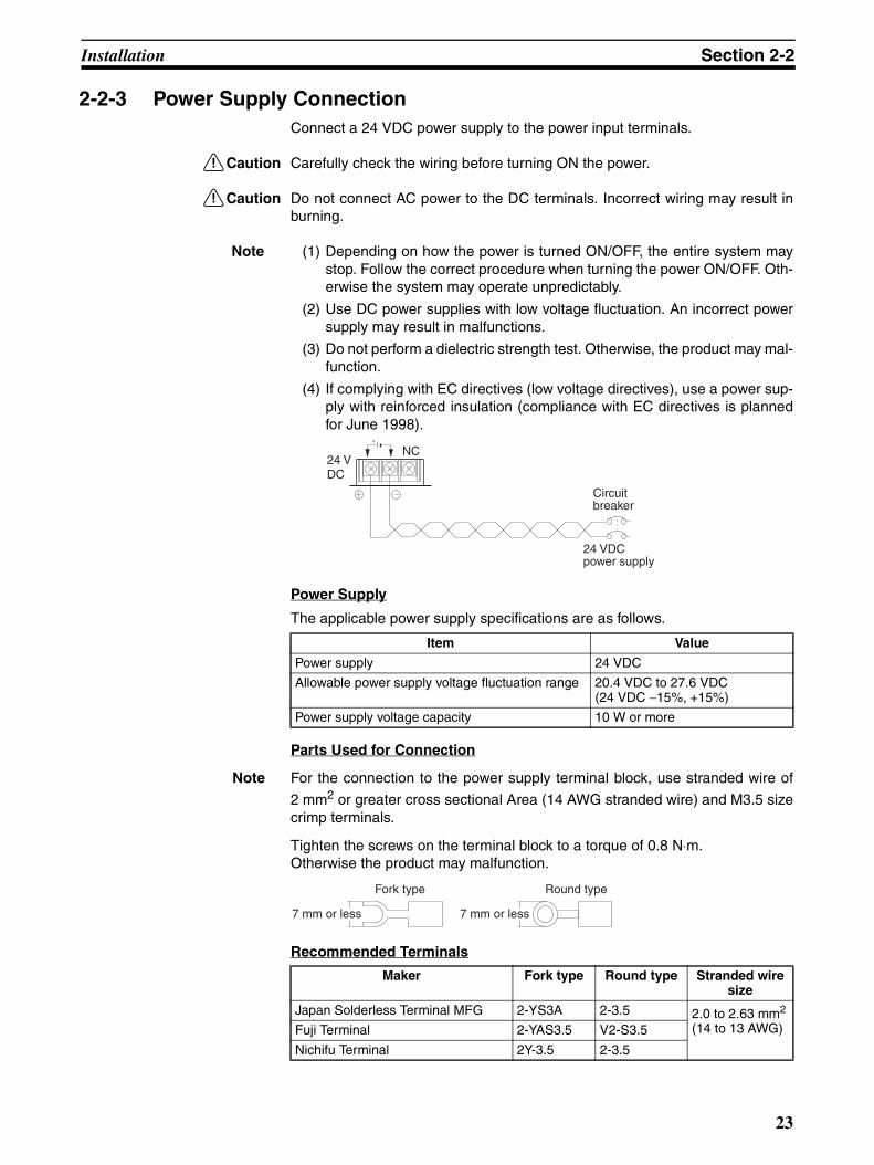
2-2-3 Power Supply ConnectionConnect a 24 VDC power supply to the power input terminals.
!Caution Carefully check the wiring before turning ON the power.
!Caution Do not connect AC power to the DC terminals. Incorrect wiring may result inburning.
Note (1) Depending on how the power is turned ON/OFF, the entire system maystop. Follow the correct procedure when turning the power ON/OFF. Oth-erwise the system may operate unpredictably.
(2) Use DC power supplies with low voltage fluctuation. An incorrect powersupply may result in malfunctions.
(3) Do not perform a dielectric strength test. Otherwise, the product may mal-function.
(4) If complying with EC directives (low voltage directives), use a power sup-ply with reinforced insulation (compliance with EC directives is plannedfor June 1998).
Power Supply
The applicable power supply specifications are as follows.
Parts Used for Connection
Note For the connection to the power supply terminal block, use stranded wire of
2 mm2 or greater cross sectional Area (14 AWG stranded wire) and M3.5 sizecrimp terminals.
Tighten the screws on the terminal block to a torque of 0.8 N⋅m.Otherwise the product may malfunction.
Recommended Terminals
Item Value
Power supply 24 VDC
Allowable power supply voltage fluctuation range 20.4 VDC to 27.6 VDC(24 VDC −15%, +15%)
Power supply voltage capacity 10 W or more
24 VDC
Circuit breaker
24 VDC power supply
NC
Maker Fork type Round type Stranded wire size
Japan Solderless Terminal MFG 2-YS3A 2-3.5 2.0 to 2.63 mm2
(14 to 13 AWG)Fuji Terminal 2-YAS3.5 V2-S3.5
Nichifu Terminal 2Y-3.5 2-3.5
Fork type Round type
7 mm or less 7 mm or less
23

Connecting Link Adapters and RS-422A Converters Section 2-3
2-3 Connecting Link Adapters and RS-422A ConvertersThis section describes the installation of the NT-AL001 Link Adapter andCJ1W-CIF11 RS-422A Converter, including the external dimensions, proce-dure for mounting and removal, and specifications. Refer to this informationwhen designing the control panel. For further details, refer to the InstructionSheet supplied with the NT-AL001 or CJ1W-CIF11.
2-3-1 Connecting an CJ1W-CIF11 RS-422A ConverterThe CJ1W-CIF11 RS-422A Converter connects directly to the NT20’s serialport A or B and converts RS-232C communications to RS-422A or RS-485.The NT20 supplies power to the RS-422A Converter through pin 6 of the RS-232C connector, so an external power supply is not required.
Note 1. The RS-232C connector is not insulated from the RS-422A/RS-485 con-nector within the CJ1W-CIF11 RS-422A Converter. If there are concernsabout differences in ground potential or noise, we recommend using theNT-AL001 Link Adapter.
2. Always turn OFF the NT20’s power supply before installing/removing a RS-422A Converter or connecting/disconnecting cables.
3. Always discharge any static electricity by touching a grounded object be-fore installing the RS-422A Converter or connecting cables.
Specifications
General Specifications
RS-232C Connector
Item Specification
Dimensions 18.2 × 34.0 × 38.8 mm (W × H × D)
Weight 20 g max.
Ambient operating temperature 0 to 55°CAmbient storage temperature –20 to 75°CAmbient operating humidity 10% to 90% (with no condensation)
Rated power supply voltage 5 V (Supplied from pin 6 of the RS-232C connec-tor.)Current consumption 40 mA max.
Operating atmosphere No corrosive gases
Vibration resistance Same as NT20 Series.
Shock resistance Same as NT20 Series.
Isolation method Not isolated
Maximum communications distance 50 m (Use the NT-AL001 if the total communications distance exceeds 50 m.)
Connector Pin Arrangement for RS-232C Port
Pin number Signal
1 FG
2 RD
3 SD
4 CS
5 RS
6 +5V
7, 8 NC
9 SG
Hood NC
24
Connecting Link Adapters and RS-422A Converters Section 2-3
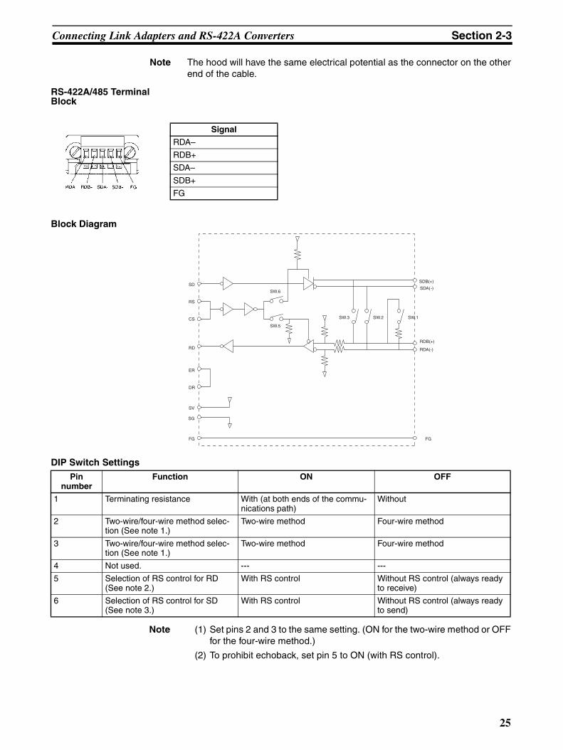
Note The hood will have the same electrical potential as the connector on the otherend of the cable.
RS-422A/485 Terminal Block
Block Diagram
DIP Switch Settings
Note (1) Set pins 2 and 3 to the same setting. (ON for the two-wire method or OFFfor the four-wire method.)
(2) To prohibit echoback, set pin 5 to ON (with RS control).
Signal
RDA–
RDB+
SDA–
SDB+
FG
SD
RS
CS
RD
ER
DR
SV
SG
FG
SW.6
SW.5
SW.2SW.3 SW.1
SDB(+)
SDA(-)
RDB(+)
RDA(-)
FG
Pin number
Function ON OFF
1 Terminating resistance With (at both ends of the commu-nications path)
Without
2 Two-wire/four-wire method selec-tion (See note 1.)
Two-wire method Four-wire method
3 Two-wire/four-wire method selec-tion (See note 1.)
Two-wire method Four-wire method
4 Not used. --- ---
5 Selection of RS control for RD (See note 2.)
With RS control Without RS control (always ready to receive)
6 Selection of RS control for SD (See note 3.)
With RS control Without RS control (always ready to send)
25
Connecting Link Adapters and RS-422A Converters Section 2-3
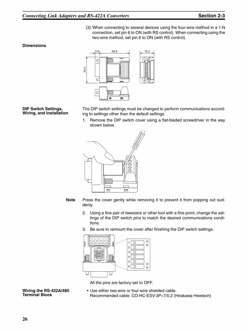
(3) When connecting to several devices using the four-wire method in a 1:Nconnection, set pin 6 to ON (with RS control). When connecting using thetwo-wire method, set pin 6 to ON (with RS control).
Dimensions
DIP Switch Settings, Wiring, and Installation
The DIP switch settings must be changed to perform communications accord-ing to settings other than the default settings.
1. Remove the DIP switch cover using a flat-bladed screwdriver in the wayshown below.
Note Press the cover gently while removing it to prevent it from popping out sud-denly.
2. Using a fine pair of tweezers or other tool with a fine point, change the set-tings of the DIP switch pins to match the desired communications condi-tions.
3. Be sure to remount the cover after finishing the DIP switch settings.
All the pins are factory-set to OFF.
Wiring the RS-422A/485 Terminal Block
• Use either two-wire or four-wire shielded cable.Recommended cable: CO-HC-ESV-3P×7/0.2 (Hirakawa Hewtech)
38.8 18.25.8
34.0
1
2
3
4
5
6
ON
ON
26
Connecting Link Adapters and RS-422A Converters Section 2-3
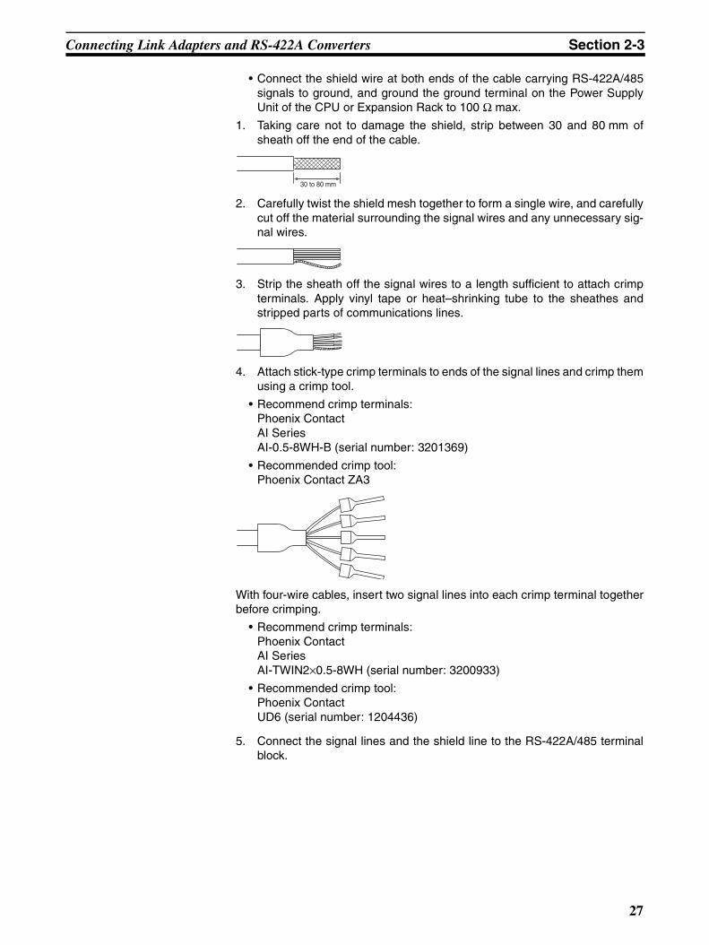
• Connect the shield wire at both ends of the cable carrying RS-422A/485signals to ground, and ground the ground terminal on the Power SupplyUnit of the CPU or Expansion Rack to 100 Ω max.
1. Taking care not to damage the shield, strip between 30 and 80 mm ofsheath off the end of the cable.
2. Carefully twist the shield mesh together to form a single wire, and carefullycut off the material surrounding the signal wires and any unnecessary sig-nal wires.
3. Strip the sheath off the signal wires to a length sufficient to attach crimpterminals. Apply vinyl tape or heat–shrinking tube to the sheathes andstripped parts of communications lines.
4. Attach stick-type crimp terminals to ends of the signal lines and crimp themusing a crimp tool.
• Recommend crimp terminals:Phoenix ContactAI SeriesAI-0.5-8WH-B (serial number: 3201369)
• Recommended crimp tool:Phoenix Contact ZA3
With four-wire cables, insert two signal lines into each crimp terminal togetherbefore crimping.
• Recommend crimp terminals:Phoenix ContactAI SeriesAI-TWIN2×0.5-8WH (serial number: 3200933)
• Recommended crimp tool:Phoenix ContactUD6 (serial number: 1204436)
5. Connect the signal lines and the shield line to the RS-422A/485 terminalblock.
30 to 80 mm
27

Connecting Link Adapters and RS-422A Converters Section 2-3
RS-422A/485 Cable Shield Connections
When using the CJ1W-CIF11 (with or without the NT-AL001), connect the sig-nal lines, shields, and grounds as shown in the following diagram.
2-3-2 Connecting an NT-AL001 Link AdapterThe NS-AL001 Link Adapter connects to serial port A or B of the NT20 with anRS-232C cable and converts the RS-232C communications to RS-422A orRS-485. (Serial ports A and B cannot be used simultaneously.)
The NT20 supplies +5 V power (150 mA max.) to the Link Adapter through pin6 of the RS-232C connector, so an external power supply is not required.
Note 1. The RS-232C connector is insulated from the RS-422A/RS-485 connectorwithin the NT-AL001 Link Adapter.
2. Always turn OFF the NT20’s power supply before installing/removing aLink Adapter or connecting/disconnecting cables.
PT
PT
PT
LGGR
CPU Rack
Signal line
CJ1W-CIF11
CJ1W-CIF11
CJ1W-CIF11
RS-422A/485 shield connected at both ends
CPU Unit or Commu-nications Unit
PowerSupplyUnit
28
Connecting Link Adapters and RS-422A Converters Section 2-3
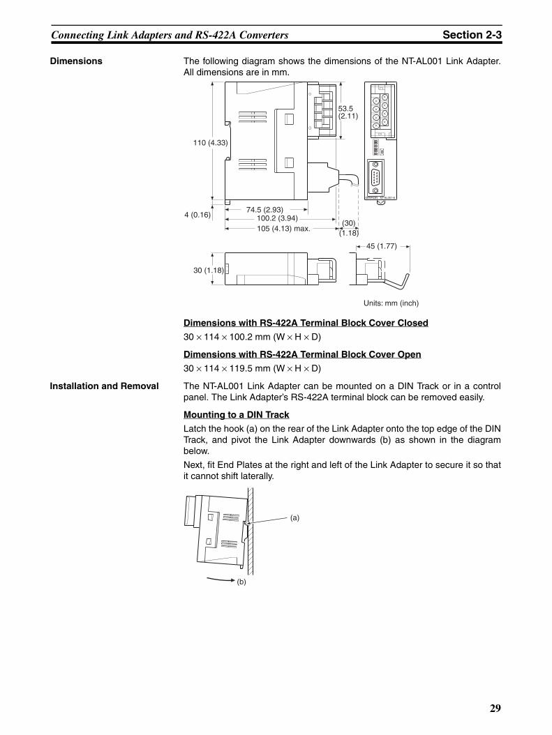
Dimensions The following diagram shows the dimensions of the NT-AL001 Link Adapter.All dimensions are in mm.
Dimensions with RS-422A Terminal Block Cover Closed
30 × 114 × 100.2 mm (W × H × D)
Dimensions with RS-422A Terminal Block Cover Open
30 × 114 × 119.5 mm (W × H × D)
Installation and Removal The NT-AL001 Link Adapter can be mounted on a DIN Track or in a controlpanel. The Link Adapter’s RS-422A terminal block can be removed easily.
Mounting to a DIN Track
Latch the hook (a) on the rear of the Link Adapter onto the top edge of the DINTrack, and pivot the Link Adapter downwards (b) as shown in the diagrambelow.
Next, fit End Plates at the right and left of the Link Adapter to secure it so thatit cannot shift laterally.
om onR NT-AL001-E
100.2 (3.94)74.5 (2.93)
110 (4.33)
4 (0.16)
30 (1.18)
45 (1.77)
53.5 (2.11)
(30)(1.18)
105 (4.13) max.
Units: mm (inch)
(b)
(a)
29
Connecting Link Adapters and RS-422A Converters Section 2-3
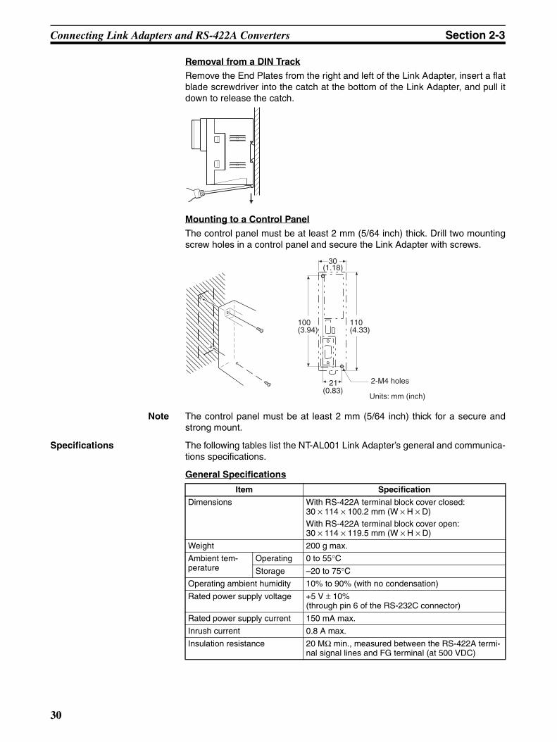
Removal from a DIN Track
Remove the End Plates from the right and left of the Link Adapter, insert a flatblade screwdriver into the catch at the bottom of the Link Adapter, and pull itdown to release the catch.
Mounting to a Control Panel
The control panel must be at least 2 mm (5/64 inch) thick. Drill two mountingscrew holes in a control panel and secure the Link Adapter with screws.
Note The control panel must be at least 2 mm (5/64 inch) thick for a secure andstrong mount.
Specifications The following tables list the NT-AL001 Link Adapter’s general and communica-tions specifications.
General Specifications
(1.18)30
21
100(3.94)
110(4.33)
2-M4 holes
Units: mm (inch)(0.83)
Item Specification
Dimensions With RS-422A terminal block cover closed:30 × 114 × 100.2 mm (W × H × D)With RS-422A terminal block cover open:30 × 114 × 119.5 mm (W × H × D)
Weight 200 g max.
Ambient tem-perature
Operating 0 to 55°CStorage –20 to 75°C
Operating ambient humidity 10% to 90% (with no condensation)
Rated power supply voltage +5 V ± 10%(through pin 6 of the RS-232C connector)
Rated power supply current 150 mA max.
Inrush current 0.8 A max.
Insulation resistance 20 MΩ min., measured between the RS-422A termi-nal signal lines and FG terminal (at 500 VDC)
30
Connecting Link Adapters and RS-422A Converters Section 2-3
Communications Specifications (RS-232C Interface)
Communications Specifications (RS-422A/485 Interface)
Dielectric strength 1,500 VAC for 1 minute between the RS-422A termi-nal signal lines and the FG terminal
Leakage current: 10 mA max.
Operating environment No corrosive gases
Vibration resistance Conforms to JIS C0911, 60 minutes each in X, Y, and Z directions
Shock resistance Conforms to JIS C0912, 147 m/s2, 3 times each in X, Y, and Z directions
Item Specification
Baud rate 115.2k bps max.
Transmission distance 2 m max.
Connector 9-pin D-SUB connector (female)
Item Specification
Baud rate 115.2k bps max. (depends on the RS-232C baud rate)
Transmission distance 500 m max.
Terminal block configuration 8-terminal detachable terminal block, M3.0
Item Specification
31

Connecting Link Adapters and RS-422A Converters Section 2-3
DIP Switch Settings The NT-AL001 Link Adapter has a 6-pin DIP switch that sets the RS-422A/RS-485 communications conditions. Set the DIP switch before connecting thecommunications cable.
When using Host Link or 1:1 NT Link communications, set the RS-422A sendmode to “no RS/CS control” by turn OFF both SW1-5 and SW1-6.
When using 1:N NT Link communications (standard or high-speed), set thecommunications mode to “RS/CS control” by turning ON either pin SW1-5 orSW1-6.
Note 1. Do not turn ON both SW1-5 and SW1-6 at the same time. This may dam-age internal circuits.
2. The power supply to the device supplying +5 V must be turned OFF beforestarting wiring work.
3. Before connecting the RS-232C cable and turning ON the power to an RS-232C device such as a PT (i.e., turning ON the power to the Link Adapter),check that the cable is wired correctly and that the DIP switch settings arecorrect. If the power is turned ON and there is a wiring fault, the internalcircuits of the Link Adapter or the RS-232C device may be damaged.
1 2 3 4 5 6
OFFON
SW1-3 SW1-4
ONom onR NT-AL001-E
(Factory settings)
SW1-1: Not used (always ON)
SW1-2: Built-in terminator setting- OFF Terminator not set- ON Terminator set
SW1-3 and SW1-4: 2-wire/4-wire
2-wire (RS-485)
SW1-3 SW1-4 OFFON 4-wire (RS-422A)
SW1-5 SW1-6
SW1-5 SW1-6
SW1-5 SW1-6
SW1-5 and SW1-6: RS-422A send mode
No RS/CS control
RS-232C CS control (high)(Data sent at CS high)
RS-232C CS control (low)(Data sent at CS low)
OFFON
OFFON
OFFON
32
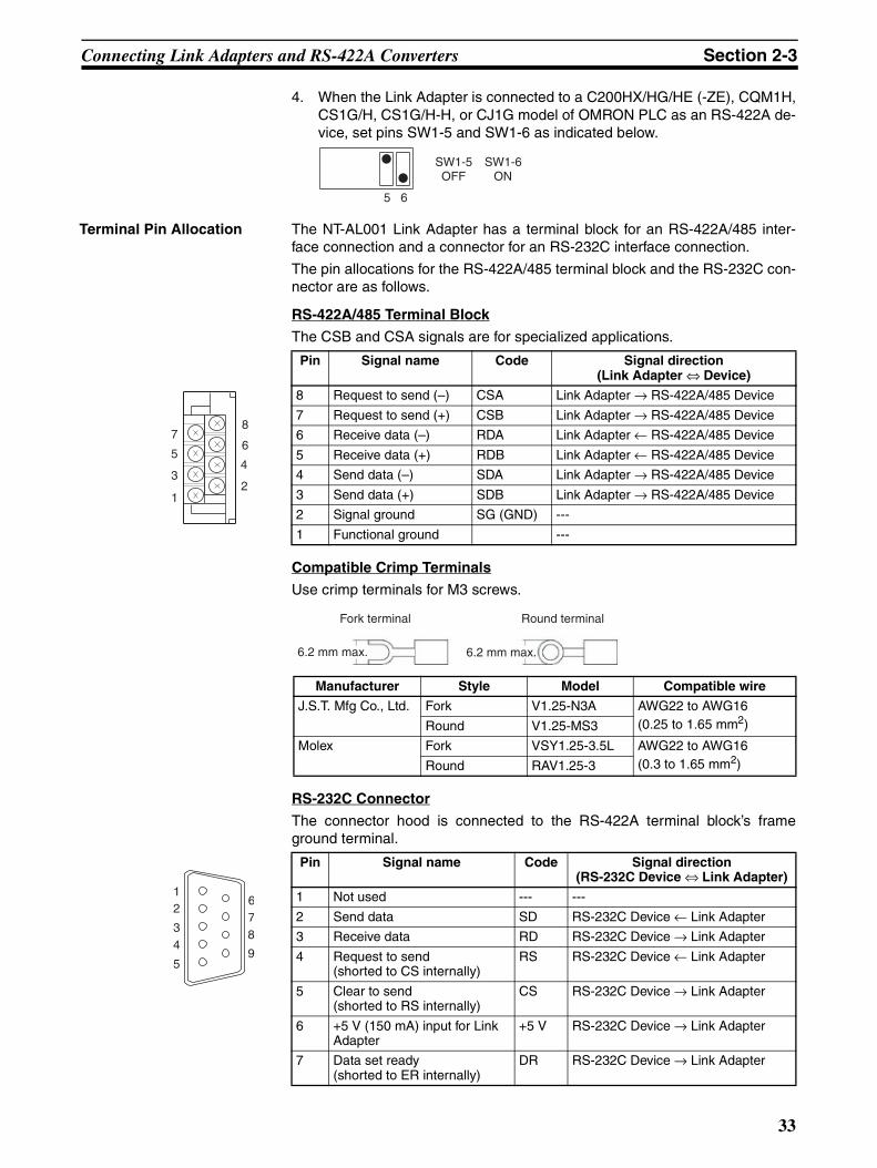
Connecting Link Adapters and RS-422A Converters Section 2-3
4. When the Link Adapter is connected to a C200HX/HG/HE (-ZE), CQM1H,CS1G/H, CS1G/H-H, or CJ1G model of OMRON PLC as an RS-422A de-vice, set pins SW1-5 and SW1-6 as indicated below.
Terminal Pin Allocation The NT-AL001 Link Adapter has a terminal block for an RS-422A/485 inter-face connection and a connector for an RS-232C interface connection.
The pin allocations for the RS-422A/485 terminal block and the RS-232C con-nector are as follows.
RS-422A/485 Terminal Block
The CSB and CSA signals are for specialized applications.
Compatible Crimp Terminals
Use crimp terminals for M3 screws.
RS-232C Connector
The connector hood is connected to the RS-422A terminal block’s frameground terminal.
5 6
SW1-5 OFF
SW1-6 ON
Pin Signal name Code Signal direction (Link Adapter ⇔ Device)
8 Request to send (–) CSA Link Adapter → RS-422A/485 Device
7 Request to send (+) CSB Link Adapter → RS-422A/485 Device
6 Receive data (–) RDA Link Adapter ← RS-422A/485 Device
5 Receive data (+) RDB Link Adapter ← RS-422A/485 Device
4 Send data (–) SDA Link Adapter → RS-422A/485 Device
3 Send data (+) SDB Link Adapter → RS-422A/485 Device
2 Signal ground SG (GND) ---
1 Functional ground ---
Manufacturer Style Model Compatible wire
J.S.T. Mfg Co., Ltd. Fork V1.25-N3A AWG22 to AWG16 (0.25 to 1.65 mm2)Round V1.25-MS3
Molex Fork VSY1.25-3.5L AWG22 to AWG16 (0.3 to 1.65 mm2)Round RAV1.25-3
Pin Signal name Code Signal direction (RS-232C Device ⇔ Link Adapter)
1 Not used --- ---
2 Send data SD RS-232C Device ← Link Adapter
3 Receive data RD RS-232C Device → Link Adapter
4 Request to send(shorted to CS internally)
RS RS-232C Device ← Link Adapter
5 Clear to send(shorted to RS internally)
CS RS-232C Device → Link Adapter
6 +5 V (150 mA) input for Link Adapter
+5 V RS-232C Device → Link Adapter
7 Data set ready(shorted to ER internally)
DR RS-232C Device → Link Adapter
7
5
3
1
8
6
4
2
Fork terminal
6.2 mm max.
Round terminal
6.2 mm max.
678
9
12
34
5
33
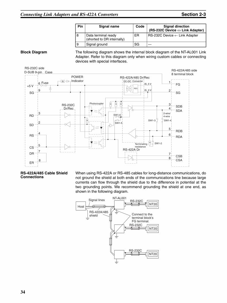
Connecting Link Adapters and RS-422A Converters Section 2-3
Block Diagram The following diagram shows the internal block diagram of the NT-AL001 LinkAdapter. Refer to this diagram only when wiring custom cables or connectingdevices with special interfaces.
RS-422A/485 Cable Shield Connections
When using RS-422A or RS-485 cables for long-distance communications, donot ground the shield at both ends of the communications line because largecurrents can flow through the shield due to the difference in potential at thetwo grounding points. We recommend grounding the shield at one end, asshown in the following diagram.
8 Data terminal ready(shorted to DR internally)
ER RS-232C Device ← Link Adapter
9 Signal ground SG ---
Pin Signal name Code Signal direction (RS-232C Device ⇔ Link Adapter)
SW1-6
R
R
D-SUB 9-pin Case
+5 V
SG
SD
RD
RS
CS
DR
ER
6
9
2
3
4
5
7
8
POWER Indicator
RS-232C Dr/Rec
RS-422A/485 Dr/RecDC-DC
IS_5 V
IS_0 V
FG1
2
34
6
5
78
SW1-5SW1-4
SG
SDBSDA
RDB
RDA
CSBCSA
SW1-2
RS-422A Dr
SW1-3
RS-232C side
FuseConverter
Photocoupler R R
R
R
L L REG
RS-422A/485 side 8 terminal block
2-wire/ 4-wire
Terminating resistance
RS-232C
RS-232C
RS-232C
NT20
NT20
NT20
Host
Signal linesNT-AL001
RS-422A/485 shield Connect to the
terminal block's FG terminal.
34
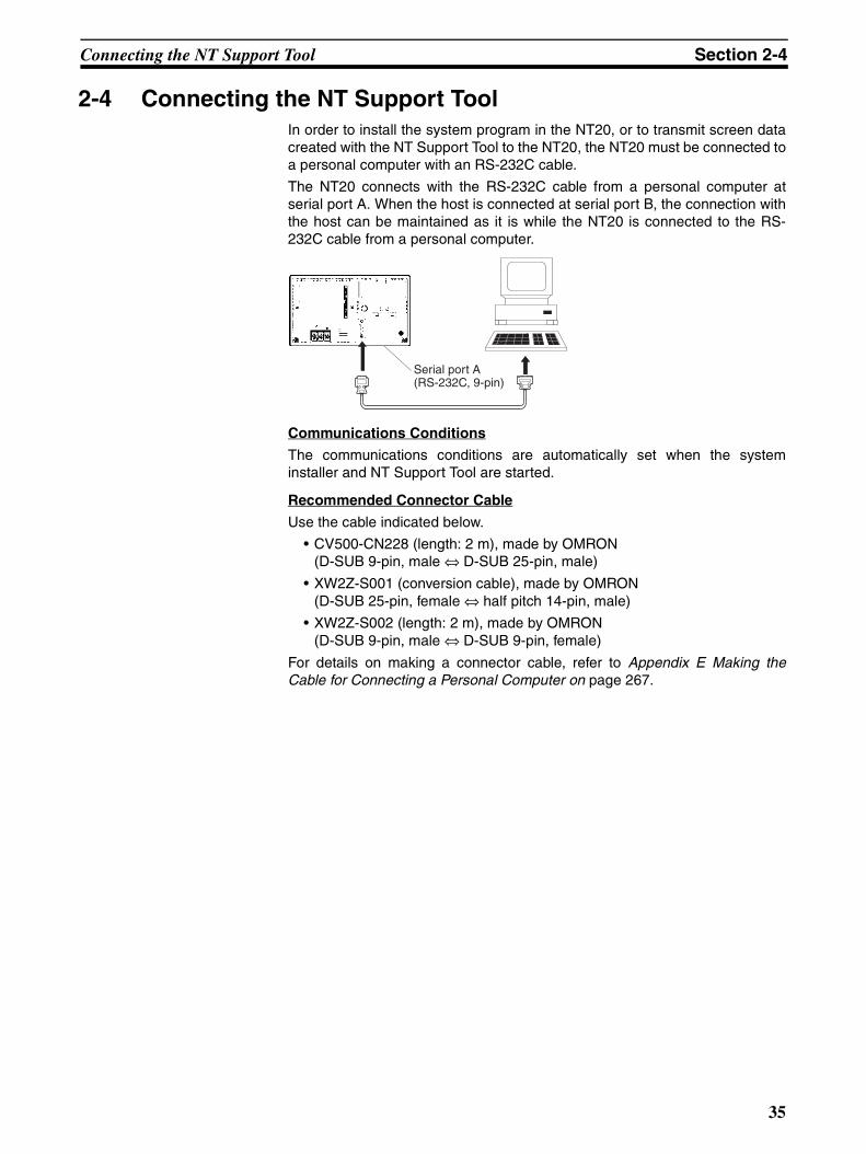
Connecting the NT Support Tool Section 2-4
2-4 Connecting the NT Support ToolIn order to install the system program in the NT20, or to transmit screen datacreated with the NT Support Tool to the NT20, the NT20 must be connected toa personal computer with an RS-232C cable.
The NT20 connects with the RS-232C cable from a personal computer atserial port A. When the host is connected at serial port B, the connection withthe host can be maintained as it is while the NT20 is connected to the RS-232C cable from a personal computer.
Communications Conditions
The communications conditions are automatically set when the systeminstaller and NT Support Tool are started.
Recommended Connector Cable
Use the cable indicated below.
• CV500-CN228 (length: 2 m), made by OMRON(D-SUB 9-pin, male ⇔ D-SUB 25-pin, male)
• XW2Z-S001 (conversion cable), made by OMRON(D-SUB 25-pin, female ⇔ half pitch 14-pin, male)
• XW2Z-S002 (length: 2 m), made by OMRON(D-SUB 9-pin, male ⇔ D-SUB 9-pin, female)
For details on making a connector cable, refer to Appendix E Making theCable for Connecting a Personal Computer on page 267.
Serial port A (RS-232C, 9-pin)
35

Using a Memory Unit Section 2-5
2-5 Using a Memory UnitThis section explains how to use a Memory Unit with the NT20. By installing aMemory Unit (NT-MF261) on the NT20, the system program or the screendata in the NT20 can be recorded (backed up) in the Memory Unit.
In addition, the system program or the screen data in the Memory Unit can beautomatically read into the NT20 when it starts up. This means that systemprogram and screen data can be changed easily at the operation site withoutconnecting to the NT Support Tool.
The data in the Memory Unit is retained without backup by a battery or othermeans.
In systems where there are frequent setup changes, by preparing a number ofMemory Units in advance and recording screen data in them according to thecontrol performed in each case, the NT20 screen data can be changed simplyby installing the Memory Unit, without connecting to the NT Support Tool.
Even if NT20 is replaced, the previous status can be maintained simply byinstalling the Memory Unit that retains the system program and screen data ofthe previous NT20.
By using the following combinations, data can be stored (backed up) to aMemory Unit.
• Screen data for two PTs.
• System program for two PTs.
• System program and screen data for one PT.
One Memory Unit can store the screen data for two PTs.
Note (1) Make sure that the power supply to the PT is OFF before connecting ordisconnecting a Memory Unit. After mounting a Memory Unit, be sure totighten its two screws. Otherwise the product may malfunction.
(2) During data transmission, do not turn OFF the power supply to the NT20.
(3) Do not touch the PCB (printed circuit board) with bare hands. Also, dis-charge any static electricity by touching a grounded object before con-necting or disconnecting a Memory Unit. Static electricity may cause thecomponents to malfunction.
(4) Be sure that the combination of the system program and screen data iscorrect in the NT20 before transferring data from the Memory Unit to theNT20. If the system program and screen data are not combined correctly,unexpected operation may result.
Reference:• When a Memory Unit is mounted, the NT20 cannot be set to the operating
status. On completion of data transmission with a Memory Unit, alwaysdisconnect the Memory Unit from the NT20 before starting NT20 opera-tion.
• One Memory Unit can store a system program for up to two PTs of differ-ent models. In order to transmit a system program from the Memory Unitto the NT20, the system program must be compatible to the target PTmodel.
• The status of memory switch settings can be recorded to the Memory Unitbesides screen data. When the data in the Memory Unit is written into theNT20, make sure that these settings can be adapted to the NT20 usedbefore transmission.
36

Using a Memory Unit Section 2-5
2-5-1 Installation MethodInstall the Memory Unit (NT-MF261) at the expansion interface connector atthe rear of the NT20 as shown in the figure below.
2-5-2 Method of UseAs shown in the figure below, a Memory Unit has 2 four-pin DIP switches, andthe operation is determined by the DIP switch settings at startup.
Note Always confirm that the power to the NT20 is OFF before setting the DIPswitches.
DIP Switch Functions The functions of the DIP switches on the Memory Unit are indicated in thetable below.
SW1
SW2
Mounting screws
Screw hole
4321
OFF
SW1 SW2
OFF
4321
Factory setting is turned all to OFF.
Pin Function
SW1-1 Automatic transmission (writing from the Mem-ory Unit to the PT)
OFF: Not executed
ON: Executed
SW1-2 Automatic transmission (writing from the PT to the Memory Unit)
OFF: Not executed
ON: Executed
SW1-3 Manual transmission (Direction of transmission and bank used selected at the PT touch panel)
OFF: Not executed
ON: Executed
SW1-4 Data type to transfer OFF: Screen data
ON: System program
Pin Function
SW2-1 Disable/enable writing to PT OFF: Disable
ON: Enable
SW2-2 Disable/enable writing to the Memory Unit OFF: Disable
ON: Enabled
SW2-3 Area (bank) selection of automatic transmission (See note.)
OFF: Bank 0
ON: Bank 1
SW2-4 System/Screen simultaneous transmission OFF: Disable
ON: Enable
37
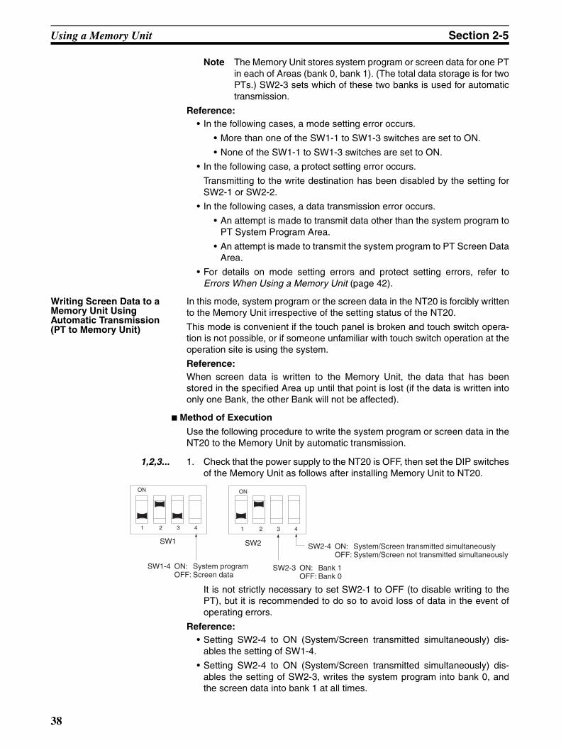
Using a Memory Unit Section 2-5
Note The Memory Unit stores system program or screen data for one PTin each of Areas (bank 0, bank 1). (The total data storage is for twoPTs.) SW2-3 sets which of these two banks is used for automatictransmission.
Reference:• In the following cases, a mode setting error occurs.
• More than one of the SW1-1 to SW1-3 switches are set to ON.
• None of the SW1-1 to SW1-3 switches are set to ON.
• In the following case, a protect setting error occurs.
Transmitting to the write destination has been disabled by the setting forSW2-1 or SW2-2.
• In the following cases, a data transmission error occurs.
• An attempt is made to transmit data other than the system program toPT System Program Area.
• An attempt is made to transmit the system program to PT Screen DataArea.
• For details on mode setting errors and protect setting errors, refer toErrors When Using a Memory Unit (page 42).
Writing Screen Data to a Memory Unit Using Automatic Transmission (PT to Memory Unit)
In this mode, system program or the screen data in the NT20 is forcibly writtento the Memory Unit irrespective of the setting status of the NT20.
This mode is convenient if the touch panel is broken and touch switch opera-tion is not possible, or if someone unfamiliar with touch switch operation at theoperation site is using the system.
Reference:When screen data is written to the Memory Unit, the data that has beenstored in the specified Area up until that point is lost (if the data is written intoonly one Bank, the other Bank will not be affected).
Method of Execution
Use the following procedure to write the system program or screen data in theNT20 to the Memory Unit by automatic transmission.
1,2,3... 1. Check that the power supply to the NT20 is OFF, then set the DIP switchesof the Memory Unit as follows after installing Memory Unit to NT20.
It is not strictly necessary to set SW2-1 to OFF (to disable writing to thePT), but it is recommended to do so to avoid loss of data in the event ofoperating errors.
Reference:• Setting SW2-4 to ON (System/Screen transmitted simultaneously) dis-
ables the setting of SW1-4.
• Setting SW2-4 to ON (System/Screen transmitted simultaneously) dis-ables the setting of SW2-3, writes the system program into bank 0, andthe screen data into bank 1 at all times.
SW1-4 ON: System programOFF: Screen data
SW2-3 ON: Bank 1OFF: Bank 0
SW2-4 ON: System/Screen transmitted simultaneouslyOFF: System/Screen not transmitted simultaneously
4321
ON
SW1 SW2
4321
ON
38

Using a Memory Unit Section 2-5
2. Turn the NT20 power ON.
The screen data is automatically written into the Memory Unit. The screendata in the NT20 is preserved.
The messages Preparing, Transmitting, Verifying, and Finished are dis-played on the screen according to the progress of data writing.
At the same time, the progress of the data writing status is displayed by themeans of the number of bytes and blocks (1 bank = 16 block = 1024k byte).
RUN Indicator operates as follows according to the processing status.
Preparing: flashes at intervals of 1 second
Transmitting: flashes at intervals of 0.5 second
Verifying: flashes at intervals of 0.5 second
Finished: lights up
3. Turn the NT20 power OFF, remove the Memory Unit.
To operate NT20 continuously, turn the NT20 power back ON.
Writing Screen Data to the PT Using Automatic Transmission (Memory Unit to PT)
In this mode, the system program or screen data in the Memory Unit is forciblywritten to NT20 irrespective of the setting status of the NT20.
Since data transmission by this method is faster than when the NT SupportTool or system installer is used, it can save a lot of time. When transmitting thesame system program or screen data to multiple NT20, this mode becomesconvenient.
Reference:When data is written to the NT20, the data that has been stored up until thatpoint is lost. When the system program is changed, the operation of NT20also changes.
Method of Execution
Use the following procedure to write the screen data in Memory Unit to theNT20 by automatic transmission.
1,2,3... 1. Check that the NT20 power is OFF, then set the DIP switches on the Mem-ory Unit as follows after installing Memory Unit to NT20.
It is not strictly necessary to set SW2-2 to OFF (to disable writing to theMemory Unit), but it is recommended to do so to avoid loss of data in theevent of operating errors.
SW2-4 ON: System/Screen transmitted simultaneouslyOFF: System/Screen not transmitted simultaneously
SW1-4 ON: System programOFF: Screen data
SW2-3 ON: Bank 1OFF: Bank 0
4321
ON
SW1 SW2
4321
ON
39

Using a Memory Unit Section 2-5
Reference:• Setting SW2-4 to ON (System/Screen transmitted simultaneously) dis-
ables the setting of SW1-4.
• Setting SW2-4 to ON (System/Screen transmitted simultaneously) dis-ables the setting of SW2-3. In this case, the data transmission becomespossible only if the data inside Memory Unit is in either of following combi-nations.
Bank 0: system program, Bank 1: other than system program
Bank 0: other than system program, Bank 1: system program
If the combination is not as listed above, a data transmitting error occurs.
• When writing the system program into the NT20, the type of system pro-gram inside Memory Unit and the PT model must correspond.
2. Turn the NT20 power ON.
The screen data is automatically written into the PT.
The messages Preparing, Transmitting, Verifying and Finished are dis-played on the screen according to the progress of data writing.
At the same time, the progress of data writing status is displayed by themeans of the number of bytes and blocks (1 bank = 16 block = 1024k byte).
The RUN Indicator operates as follows according to the processing status.
Preparing: flashes at intervals of 1 second
Transmitting: flashes at intervals of 0.5 second
Verifying: flashes at intervals of 0.5 second
Finished: lights up
3. Turn the NT20 power OFF, remove the Memory Unit.
To operate NT20 continuously, turn the NT20 power back ON.
Reading and Writing Data by Manual Transmission
In this method, the direction of transmission and Area of the Memory Unitused are set by touch switch operations at the NT20. Transmission can beexecuted while checking the settings.
Reference:When data is written to the NT20 or Memory Unit, the data that has beenstored up until that point is lost.
Method of Execution
Use the following procedure to write screen data using manual transmission.
1,2,3... 1. Check that the NT20 power is OFF, then set the DIP switches on the Mem-ory Unit as follows.
In order to avoid loss of data in the event of operating errors, it is advisableto set SW2-1 and SW2-2 so as to disable writing to the Unit from which thedata is to be read.
2. Turn the NT20 power ON.
Display language select screen appears.
Setting of SW1-4 not relevant Setting of SW2-3 not relevant
Setting of SW2-4 not relevant
4321
ON
SW1 SW2
4321
ON
40

Using a Memory Unit Section 2-5
3. Press the Japanese or English touch switches to select the display lan-guage.
The screen shown below is displayed.
Current PT Screen Data, System
The first line: System program name and version for the system programinside the PT.
The second line: Resource name and version for the resource inside thePT.
Current PT Screen Data, Screen
The comment for the screen data in the NT20 is displayed here.
Current Memory Unit Screen Data
• System Program:
The first line: System program name and version for the system programinside the Memory Unit.
The second line: Resource name and version for the resource inside theMemory Unit.
• Screen Data:
The comment for the screen data in the NT20 is displayed here.
The available transmitting destinations are altered depending on the settingsof the source of transmitting as described in the table below
Reference:• When transmitting the system program and screen data simultaneously
from the PT to the Memory Unit, the setting of banks is Bank 0: systemprogram, Bank 1: screen data, and when transmitting them from theMemory Unit to the PT, either of the following combinations must be used.
Bank 0: system program, Bank 1: other than system program
Bank 0: other than system program, Bank 1: system program
• When writing the system program into the NT20, the type of system pro-gram inside Memory Unit and the PT model must correspond.
Source Description
[PT]screen
[PT]system
[PT]system/screen [Memory Unit] Bank 0/1 (fixed)
[Memory Unit] Bank 0 • If system program is selected
[PT]system (fixed)• If screen data is selected
[PT]screen (fixed)
[Memory Unit] Bank 1
[Memory Unit] Bank 0/1 [PT]system/screen (fixed)
[Memory Unit] Bank 0 [Memory Unit] Bank 1
41
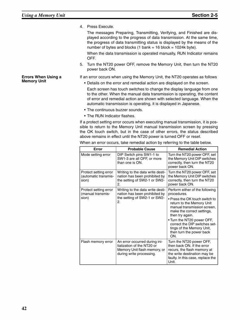
Using a Memory Unit Section 2-5
4. Press Execute.
The messages Preparing, Transmitting, Verifying, and Finished are dis-played according to the progress of data transmission. At the same time,the progress of data transmitting status is displayed by the means of thenumber of bytes and blocks (1 bank = 16 block = 1024k byte).
When the data transmission is operated manually, RUN Indicator remainsOFF.
5. Turn the NT20 power OFF, remove the Memory Unit, then turn the NT20power back ON.
Errors When Using a Memory Unit
If an error occurs when using the Memory Unit, the NT20 operates as follows
• Details on the error and remedial action are displayed on the screen.
Each screen has touch switches to change the display language from oneto the other. When the manual data transmission is operating, the contentof error and remedial action are shown with selected language. When theautomatic transmission is operating, it is displayed in Japanese.
• The continuous buzzer sounds.
• The RUN Indicator flashes.
If a protect setting error occurs when executing manual transmission, it is pos-sible to return to the Memory Unit manual transmission screen by pressingthe OK touch switch, but in the case of other errors, the status describedabove remains in effect until the NT20 power is turned OFF or reset.
When an error occurs, take remedial action by referring to the table below.
Error Probable Cause Remedial Action
Mode setting error DIP Switch pins SW1-1 to SW1-3 are all OFF, or more than one is ON.
Turn the NT20 power OFF, set the Memory Unit DIP switches correctly, then turn the NT20 power back ON.
Protect setting error (automatic transmis-sion)
Writing to the data write desti-nation has been prohibited by the setting of SW2-1 or SW2-2.
Turn the NT20 power OFF, set the Memory Unit DIP switches correctly, then turn the NT20 power back ON.
Protect setting error (manual transmis-sion)
Writing to the data write desti-nation has been prohibited by the setting of SW2-1 or SW2-2.
Perform either of the following procedures.• Press the OK touch switch to
return to the Memory Unit manual transmission screen, make the correct settings, then try again.
• Turn the NT20 power OFF, correct the DIP switches set-tings of the Memory Unit, then turn the power back ON.
Flash memory error An error occurred during ini-tialization of the NT20 or Memory Unit flash memory, or during write processing.
Turn the NT20 power OFF, then back ON. If the error recurs, the flash memory at the write destination may be faulty. In this case, replace the Unit.
42
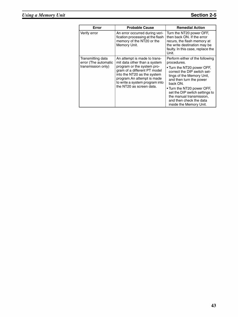
Using a Memory Unit Section 2-5
Verify error An error occurred during veri-fication processing at the flash memory of the NT20 or the Memory Unit.
Turn the NT20 power OFF, then back ON. If the error recurs, the flash memory at the write destination may be faulty. In this case, replace the Unit.
Transmitting data error (The automatic transmission only)
An attempt is made to trans-mit data other than a system program or the system pro-gram of a different PT model into the NT20 as the system program.An attempt is made to write a system program into the NT20 as screen data.
Perform either of the following procedures.• Turn the NT20 power OFF,
correct the DIP switch set-tings of the Memory Unit, and then turn the power back ON.
• Turn the NT20 power OFF, set the DIP switch settings to the manual transmission, and then check the data inside the Memory Unit.
Error Probable Cause Remedial Action
43
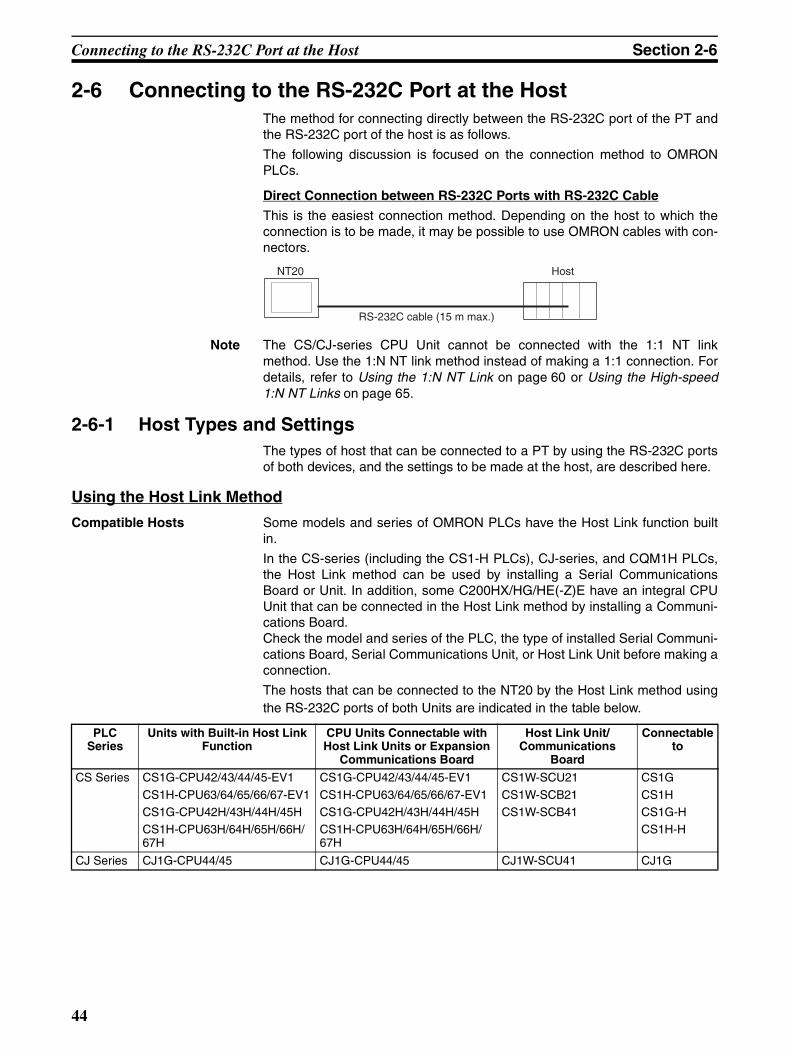
Connecting to the RS-232C Port at the Host Section 2-6
2-6 Connecting to the RS-232C Port at the HostThe method for connecting directly between the RS-232C port of the PT andthe RS-232C port of the host is as follows.
The following discussion is focused on the connection method to OMRONPLCs.
Direct Connection between RS-232C Ports with RS-232C Cable
This is the easiest connection method. Depending on the host to which theconnection is to be made, it may be possible to use OMRON cables with con-nectors.
Note The CS/CJ-series CPU Unit cannot be connected with the 1:1 NT linkmethod. Use the 1:N NT link method instead of making a 1:1 connection. Fordetails, refer to Using the 1:N NT Link on page 60 or Using the High-speed1:N NT Links on page 65.
2-6-1 Host Types and SettingsThe types of host that can be connected to a PT by using the RS-232C portsof both devices, and the settings to be made at the host, are described here.
Using the Host Link Method
Compatible Hosts Some models and series of OMRON PLCs have the Host Link function builtin.
In the CS-series (including the CS1-H PLCs), CJ-series, and CQM1H PLCs,the Host Link method can be used by installing a Serial CommunicationsBoard or Unit. In addition, some C200HX/HG/HE(-Z)E have an integral CPUUnit that can be connected in the Host Link method by installing a Communi-cations Board.Check the model and series of the PLC, the type of installed Serial Communi-cations Board, Serial Communications Unit, or Host Link Unit before making aconnection.
The hosts that can be connected to the NT20 by the Host Link method usingthe RS-232C ports of both Units are indicated in the table below.
RS-232C cable (15 m max.)
HostNT20
PLC Series
Units with Built-in Host Link Function
CPU Units Connectable with Host Link Units or Expansion
Communications Board
Host Link Unit/Communications
Board
Connectable to
CS Series CS1G-CPU42/43/44/45-EV1
CS1H-CPU63/64/65/66/67-EV1CS1G-CPU42H/43H/44H/45HCS1H-CPU63H/64H/65H/66H/67H
CS1G-CPU42/43/44/45-EV1
CS1H-CPU63/64/65/66/67-EV1CS1G-CPU42H/43H/44H/45HCS1H-CPU63H/64H/65H/66H/67H
CS1W-SCU21
CS1W-SCB21CS1W-SCB41
CS1G
CS1HCS1G-HCS1H-H
CJ Series CJ1G-CPU44/45 CJ1G-CPU44/45 CJ1W-SCU41 CJ1G
44

Connecting to the RS-232C Port at the Host Section 2-6
Note (1) Use a CPM2C-CN111 or CS1W-CN114/118 Connecting Cable, CPM1-CIF01 RS-232C Adapter, or CPM1-CIF11 RS-422A Adapter to connect.
(2) The CQM1H-CPU11 does not have a built-in RS-232C port, so connectto the PT at the peripheral port with a CS1W-CN118 Connecting Cable.
(3) CPU Units of CVM1/CV-series PLCs without the suffix -EV@ cannot beconnected.
C Series --- C200HS-CPU01/03/21/23/31/33-EC200HE-CPU11/32/42-E
C200HE-CPU11/32/42-ZEC200HG-CPU33/43/53/63-EC200HG-CPU33/43/53/63-ZE
C200HX-CPU34/44/54/64-EC200HX-CPU34/44/54/64/65/85-ZE
C200H-LK201-EV1 C200HSC200HEC200HE-Z
C200HGC200HG-ZC200HX
C200HX-Z
C200HS-CPU21/23/31/33-E --- --- C200HS
C200HE-CPU42-E
C20HE-CPU42-ZE
C200HE-CPU32/42-E
C200HE-CPU32/42-ZE
C200HW-COM02/04/
05/06-EV1
C200HE
C200HE-Z
C200HG-CPU43/63-E
C200HG-CPU43/63-ZE
C200HG-CPU33/43/53/63-E
C200HG-CPU33/43/53/63-ZE
C200HG
C200HG-Z
C200HX-CPU44/64-EC200HX-CPU44/64/65/85-ZE
C200HX-CPU34/44/54/64-EC200HX-CPU34/44/54/64/65/85-ZE
C200HXC200HX-Z
CPM1-10/20/30CDR-@+CPM1-CIF01
--- --- CPM1
CPM1A-10/20/30/40CD@-@+CPM1-CIF01
--- ---
CPM2A-30/40/60CD@@-@+CPM1-CIF01
(Peripheral port connection)
--- --- CPM2A
CPM2C-10/20@@@@@@-@(See note 1.)
--- --- CPM2C
CQM1-CPU21-ECQM1-CPU41/42/43/44-EV1
--- --- CQM1
CQM1H-CPU11/21/51/61 (See note 2.)
CQM1H-CPU51/61 CQM1H-SCB41 CQM1H
CVM1 Series (See note 3.)
CVM1-CPU01-EV2CVM1-CPU11-EV2CVM1-CPU21-EV2
CVM1-CPU01-EV2CVM1-CPU11-EV2CVM1-CPU21-EV2
CV500-LK201 CVM1
Compo-Bus/S Master Unit
SRM1-C02-V1 --- --- SRM1
PLC Series
Units with Built-in Host Link Function
CPU Units Connectable with Host Link Units or Expansion
Communications Board
Host Link Unit/Communications
Board
Connectable to
45

Connecting to the RS-232C Port at the Host Section 2-6
Settings at the Host When using the Host Link method, the settings shown below must be made atthe host (depending on the Unit, some of these settings may not be neces-sary, or settings not shown here may be necessary).
Note (1) Set the Host Link baud rate up to 115,200 bps with the memory switch atthe NT20.
(2) The 1-to-N setting enables BCC (Block Check Character). It is not actu-ally possible to connect more than one NT20 in a single Host Link.
The setting methods for each Unit are described below.
Connecting to a C-series Host Link Unit
C200H, C200HS, and C200HE/HG/HX (-Z)E Rack-mounted Unit: C200H-LK201-V1
Setting the Front Switches
Set each switch with a flat blade screwdriver so that the values or symbols inthe setting value window agree with the following.
Setting the Rear Switches
Item Switch Setting
I/O port RS-232C
Baud rate Set the same baud rate as for the NT20. (See note 1.)
Transfer code ASCII, 7 data bits, 2 stop bits
Parity Even
1-to-1/1-to-N 1-to-N (See note 2.)
Command level Level 1, 2, 3
Unit # 00
LK201
RUN RCV
XMT
ERROR
SW10 0
5 2
• Unit # (SW1, SW2)Set these switches to 0.
• Command level, parity, and transfer code (SW4)Set this switch to 2.
• Baud rate (SW3)Set this switch to 5 to select 9,600 bps.Set this switch to 6 to select 19,200 bps.
SW3
SW2
SW4
ON
1
CTS selector switchExternal
0 V (ON)
• 1-to-1/1-to-N selection (DIP switch)Set pin 3 to ON.
• CTS selection (selector switch)Set this always to 0V (ON).
234
46
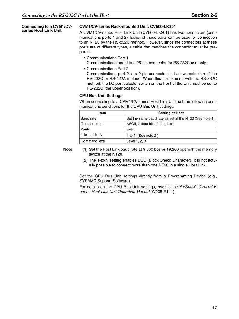
Connecting to the RS-232C Port at the Host Section 2-6
Connecting to a CVM1/CV-series Host Link Unit
CVM1/CV-series Rack-mounted Unit: CV500-LK201
A CVM1/CV-series Host Link Unit (CV500-LK201) has two connectors (com-munications ports 1 and 2). Either of these ports can be used for connectionto an NT20 by the RS-232C method. However, since the connectors at theseports are of different types, a cable that matches the connector must be pre-pared.
• Communications Port 1Communications port 1 is a 25-pin connector for RS-232C use only.
• Communications Port 2Communications port 2 is a 9-pin connector that allows selection of theRS-232C or RS-422A method. When this port is used with the RS-232Cmethod, the I/O port selector switch on the front of the Unit must be set toRS-232C (the upper position).
CPU Bus Unit Settings
When connecting to a CVM1/CV-series Host Link Unit, set the following com-munications conditions for the CPU Bus Unit settings.
Note (1) Set the Host Link baud rate at 9,600 bps or 19,200 bps with the memoryswitch at the NT20.
(2) The 1-to-N setting enables BCC (Block Check Character). It is not actu-ally possible to connect more than one NT20 in a single Host Link.
Set the CPU Bus Unit settings directly from a Programming Device (e.g.,SYSMAC Support Software).
For details on the CPU Bus Unit settings, refer to the SYSMAC CVM1/CV-series Host Link Unit Operation Manual (W205-E1-@).
Item Setting at Host
Baud rate Set the same baud rate as set at the NT20 (See note 1.)
Transfer code ASCII, 7 data bits, 2 stop bits
Parity Even
1-to-1, 1-to-N 1-to-N (See note 2.)
Command level Level 1, 2, 3
47

Connecting to the RS-232C Port at the Host Section 2-6
Setting the Front Switches
Connecting to a CS/CJ-series Serial Communications Unit
CS/CJ-series Rack-mounted Unit: CS1W-SCU21CJ-series: CJ1W-SCU41 (Port 2 is an RS-232C Port.)
Setting the Front Switches
Set the unit number of the Serial Communications Unit by using the rotaryswitch located on the front panel. Set each switch with a flat blade screwdriverso that the values or symbols in the setting value window agree with the fol-lowing.
Allocation DM Area Settings for CPU Unit
Settings are written from the Programming Device (a Programming Consoleor CX-Programmer) directly into the allocated DM Area (PLC Setup) of theCPU Unit. After the settings are written, they become effective by turning thepower ON, restarting the Unit, restarting the communications port, or execu-tion of the STUP instruction.
RS-232C
Communications port 1(RS-232C)
Communications port 2(RS-232C/RS-422A)
I/O port selector switch
RS-422A
• Unit # (SW3, SW4)
• Communications condition setting (Pin 1)Set this pin to OFF.
- Baud rate: 9,600 bps- Parity: Even- Xon/Xoff control: Not executed- Communications method: Full duplex- Stop bits: 2 stop bits- Data length: 7 bits
• I/O port selection (selector switch)Set this to RS-232C.
• CTS selection (Pins 2 and 3)Set pin 2 or 3 to ON. (Set this always to 0V.)
When using communications port 2, set these switches to 0.
To use communications port 1, turn ON pin 2. To use communications port 2, turn ON pin 3.
Communications are executed in accordance with the CPU Bus Unit system settings made at the PLC. The initial values for the system settings are as
C
SCU21RUN ERC SD1 RD1
RDYERHSD2RD2
No.FE10
CS1W-SCU21
CJ1W-SCU41
Set the unit number to 0 through F so that it will not duplicate the numbers used in other Units.
Set the unit number to 0 through F so that it will not duplicate the numbers used in other Units.
UNITNo.
FEDCBA9876543210
UNIT
48

Connecting to the RS-232C Port at the Host Section 2-6
The following table shows the words allocated in the DM Area and the set-tings.
m = DM30000 + 100 × unit number
Connecting to a CPU Unit CV-series and CVM1/CV-series (-EV@) CPU Units
CVM1-CPU01-EV2/CVM1-CPU11-EV2/CVM1-CPU21-EV2
PLC Setup
When connecting to a CVM1/CV-series CPU Unit, set the following communi-cations conditions for the PLC Setup.
Note Set the Host Link baud rate at 9,600 bps or 19,200 bps with the memoryswitch at the NT20.
Either set PLC Setup directly from a Programming Device (e.g., SYSMACSupport Software), or transmit the PLC Setup made at a Programming Deviceto the CPU Unit.
For details on the PLC Setup, refer to the SYSMAC CVM1/CV500/1000/2000Operation Manual: Ladder Diagrams (W202-E1-@).
Allocated DM word Value Settings
Port 1 Port 2
m m+10 8000 Host Link mode, 2 stop bits, even parity, data length 7 bits
m+1 m+11 0000 Baud rate: 9,600 bps.
0007 Baud rate: 19,200 bps.
0008 Baud rate: 38,400 bps.
0009 Baud rate: 57,600 bps.
000A Baud rate: 115,200 bps.
m+2 m+12 0000 Transmit delay time 0 ms.
m+3 m+13 0000 No CTS control Unit No.0 for Host Link
Item Setting at Host
Baud rate Set the same baud rate as set at the NT20 (See note.)
Stop bits 2 stop bits
Parity Even
Data length ASCII 7 bits
Unit # 00
49

Connecting to the RS-232C Port at the Host Section 2-6
Setting the Front Switches
C-series C200HS, C200HX/HG/HE(-Z)E, CPM1, CPM2A, CPM2C, CQM1, CQM1H CPU Units and SRM1
The connection method depends upon the model of PLC being used, asshown in the following table.
PLC model Connection method
C200HS, CQM1 Connect to the CPU Unit’s built-in RS-232C port.
C200HX/HG/HE(-Z)E • Connect to the CPU Unit’s built-in RS-232C port.• Connect to one of the RS-232C ports (port A or port B) on
a Serial Communications Board.
CQM1H • Connect to the CPU Unit’s built-in RS-232C port.• Connect to the peripheral port through a CS1W-CN118
Connecting Cable.• Connect to the RS-232C port (port 1) on a Serial Commu-
nications Board.
CPM1 Connect to the peripheral port through a CPM1-CIF01 RS-232C Adapter.
CPM2A, SRM1 • Connect to the CPU Unit’s built-in RS-232C port.• Connect to the peripheral port through a CPM1-CIF01 RS-
232C Adapter.
CPM2C Connect to the CPU Unit’s RS-232C port or the peripheral port through a Connecting Cable (CPM2C-CN111, CS1W-CN118, or CS1W-CN114).(The CPM2C-CN111 splits the Unit’s Communications Port into a RS-232C port and a peripheral port. A CPM1-CIF01 RS-232C Adapter is also required to connect to this periph-eral port.)
RS-232C I/O port selector switch
RS-422A
• Host Link Communications method (selector switch)
Set this to RS-232C.
• System setting (Pin 4)
Note
- DIP switch settings:
- PLC Setup:
To effect the existing DIP switch settings, set SW4 to ON.To effect the existing PLC Setup, set pin 4 to OFF.
For CPU Units manufactured before or during June 1995 (lot No. jj65), the existing DIP switch settings differ from the existing PLC Setup as follows.
2,400 bps, 1 stop bit, even parity, 7 bit data length
9,600 bps, 2 stop bits, even parity, 7 bit data length
For CPU Units manufactured from July 1995 onward (lot No. @@75), the stipulated values in the DIP switch settings also are 9,600 bps and 2 stop bits.
50

Connecting to the RS-232C Port at the Host Section 2-6
PLC Setup Settings
When connecting to a C200HS, C200HX/HG/HE(-Z)E, CPM1, CPM2A,CPM2C, CQM1, or CQM1H CPU Unit, or SRM1, set the following communi-cations conditions for the PLC Setup.
Note Set the Host Link baud rate at 9,600 bps or 19,200 bps with the memoryswitch at the NT20.
Set the PLC Setup settings directly from a Programming Device (e.g., the CX-Programmer Support Software).
For details on operations relating to the PLC Setup, refer to the manual for thePLC which is used.
The PLC Setup area word addresses and settings to be made depending onthe Unit and port to which the connection is made are shown below.
CPM2A, CPM2C, CQM1H, or SRM1: Peripheral Port Connection
C200HS, C200HX/HG/HE(-Z)E, CPM2A, CPM2C, CQM1, CQM1H (otherthan the CPU11), or SRM1: Built-in RS-232C Port Connection
C200HX/HG/HE(-Z)E: Serial Communications Board Port ACQM1H: Serial Communications Board Port 1
Item Setting at Host
Communications mode Host Link mode
Baud rate Set the same speed as set at the NT20 (See note.)
Stop bits 2 stop bits
Parity Even
Data length ASCII 7 bits
Unit # 00
Word Writing Value Settings
DM6650 0001 Host Link mode, no CTS control
Communications conditions set by the contents of DM
DM6651 0303 Data length 7 bits, 2 stop bits, even parity, baud rate: 9,600 bps
0304 Data length 7 bits, 2 stop bits, even parity, baud rate: 19,200 bps
DM6653 0000 Unit # 00
Word Writing Value Settings
DM6645 0001 Host Link mode, no CTS controlCommunications conditions set by the contents of DM
DM6646 0303 Data length 7 bits, 2 stop bits, even parity, baud rate: 9,600 bps
0304 Data length 7 bits, 2 stop bits, even parity, baud rate: 19,200 bps
DM6648 0000 Unit # 00
Word Writing Value Settings
DM6555 0001 Host Link mode, no CTS controlCommunications conditions set by the contents of DM
DM6556 0303 Data length 7 bits, 2 stop bits, even parity, baud rate: 9,600 bps
0304 Data length 7 bits, 2 stop bits, even parity, baud rate: 19,200 bps
DM6558 0000 Unit # 00
51
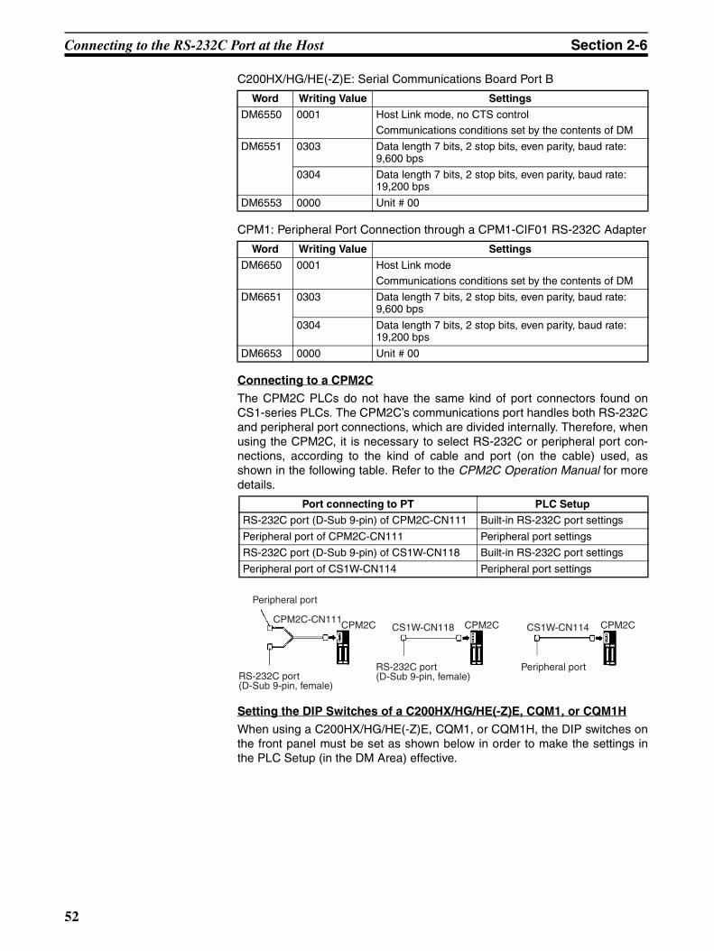
Connecting to the RS-232C Port at the Host Section 2-6
C200HX/HG/HE(-Z)E: Serial Communications Board Port B
CPM1: Peripheral Port Connection through a CPM1-CIF01 RS-232C Adapter
Connecting to a CPM2C
The CPM2C PLCs do not have the same kind of port connectors found onCS1-series PLCs. The CPM2C’s communications port handles both RS-232Cand peripheral port connections, which are divided internally. Therefore, whenusing the CPM2C, it is necessary to select RS-232C or peripheral port con-nections, according to the kind of cable and port (on the cable) used, asshown in the following table. Refer to the CPM2C Operation Manual for moredetails.
Setting the DIP Switches of a C200HX/HG/HE(-Z)E, CQM1, or CQM1H
When using a C200HX/HG/HE(-Z)E, CQM1, or CQM1H, the DIP switches onthe front panel must be set as shown below in order to make the settings inthe PLC Setup (in the DM Area) effective.
Word Writing Value Settings
DM6550 0001 Host Link mode, no CTS control
Communications conditions set by the contents of DM
DM6551 0303 Data length 7 bits, 2 stop bits, even parity, baud rate: 9,600 bps
0304 Data length 7 bits, 2 stop bits, even parity, baud rate: 19,200 bps
DM6553 0000 Unit # 00
Word Writing Value Settings
DM6650 0001 Host Link mode
Communications conditions set by the contents of DM
DM6651 0303 Data length 7 bits, 2 stop bits, even parity, baud rate: 9,600 bps
0304 Data length 7 bits, 2 stop bits, even parity, baud rate: 19,200 bps
DM6653 0000 Unit # 00
Port connecting to PT PLC Setup
RS-232C port (D-Sub 9-pin) of CPM2C-CN111 Built-in RS-232C port settings
Peripheral port of CPM2C-CN111 Peripheral port settings
RS-232C port (D-Sub 9-pin) of CS1W-CN118 Built-in RS-232C port settings
Peripheral port of CS1W-CN114 Peripheral port settings
Peripheral port
RS-232C port(D-Sub 9-pin, female)
CPM2C-CN111CPM2C
RS-232C port(D-Sub 9-pin, female)
CS1W-CN118 CPM2C
Peripheral port
CS1W-CN114 CPM2C
52

Connecting to the RS-232C Port at the Host Section 2-6
When using the CQM1H’s built-in peripheral port, turn ON SW7.
Setting the Switches of a CPM2A
When using a CPM2A, the switches on the front panel must be set as shownbelow in order to make the PLC Setup settings effective.
Setting the Switches of a CPM2C
When using a CPM2C, the switches on the front panel must be set as shownbelow in order to make the PLC Setup settings effective.
Setting the Switches on an RS-232C Adapter
When using a CPM1-CIF01 RS-232C Adapter, set the mode switch as shownin the following diagram.
C200HX/HG/HE(-Z)E CQM1 CQM1H
RS-232C port communications condition setting Set pin 5 to OFF to make the settings made in PLC Setup effective.
Set the Communications switch to OFF (down position).
• Connecting PT to peripheral port• Connecting PT to built-in RS-232C port
SW1: OFFSW2: ON
• Connecting PT to built-in RS-232C port(A Programming Console is connected to the peripheral port.)
SW1: OFFSW2: OFF
The settings for SW1 and SW2 depend upon the usage of the peripheral port and RS-232C port.
(A device that requires non-standard communications settings is connected to the peripheral port.)
CPM1Set the mode setting switch to HOST (upper position).
CPM1-CIF01
53
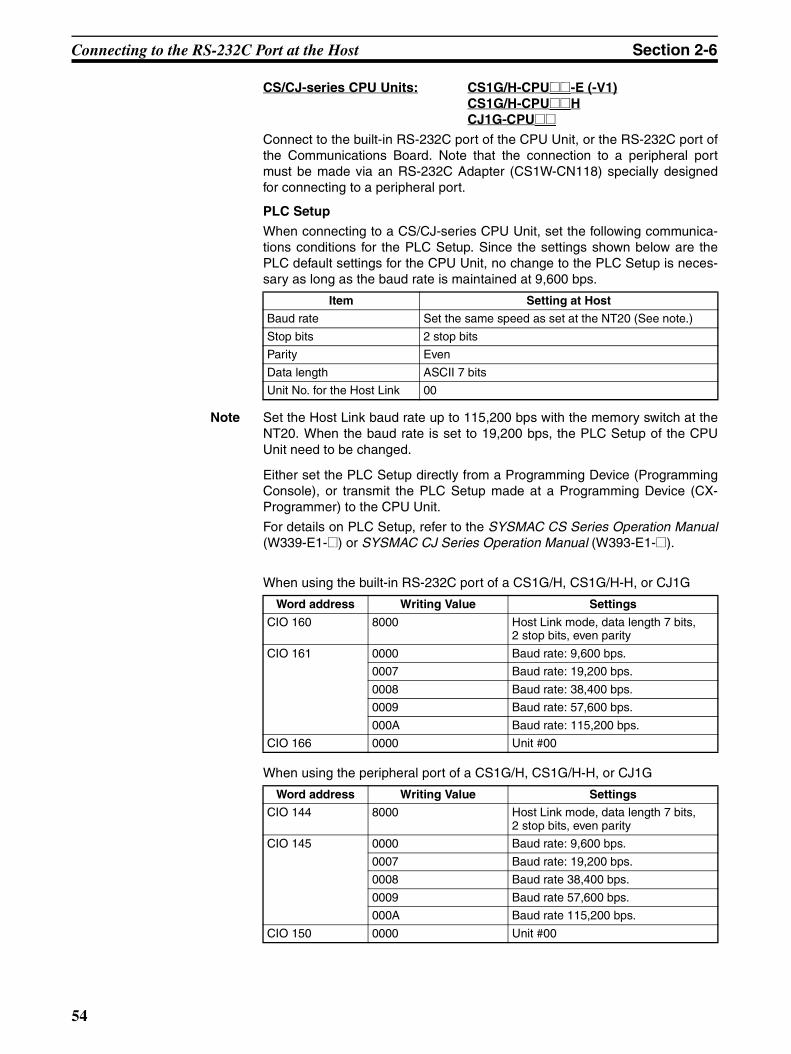
Connecting to the RS-232C Port at the Host Section 2-6
CS/CJ-series CPU Units: CS1G/H-CPU@@-E (-V1)CS1G/H-CPU@@HCJ1G-CPU@@
Connect to the built-in RS-232C port of the CPU Unit, or the RS-232C port ofthe Communications Board. Note that the connection to a peripheral portmust be made via an RS-232C Adapter (CS1W-CN118) specially designedfor connecting to a peripheral port.
PLC Setup
When connecting to a CS/CJ-series CPU Unit, set the following communica-tions conditions for the PLC Setup. Since the settings shown below are thePLC default settings for the CPU Unit, no change to the PLC Setup is neces-sary as long as the baud rate is maintained at 9,600 bps.
Note Set the Host Link baud rate up to 115,200 bps with the memory switch at theNT20. When the baud rate is set to 19,200 bps, the PLC Setup of the CPUUnit need to be changed.
Either set the PLC Setup directly from a Programming Device (ProgrammingConsole), or transmit the PLC Setup made at a Programming Device (CX-Programmer) to the CPU Unit.
For details on PLC Setup, refer to the SYSMAC CS Series Operation Manual(W339-E1-@) or SYSMAC CJ Series Operation Manual (W393-E1-@).
When using the built-in RS-232C port of a CS1G/H, CS1G/H-H, or CJ1G
When using the peripheral port of a CS1G/H, CS1G/H-H, or CJ1G
Item Setting at Host
Baud rate Set the same speed as set at the NT20 (See note.)
Stop bits 2 stop bits
Parity Even
Data length ASCII 7 bits
Unit No. for the Host Link 00
Word address Writing Value Settings
CIO 160 8000 Host Link mode, data length 7 bits, 2 stop bits, even parity
CIO 161 0000 Baud rate: 9,600 bps.
0007 Baud rate: 19,200 bps.
0008 Baud rate: 38,400 bps.
0009 Baud rate: 57,600 bps.
000A Baud rate: 115,200 bps.
CIO 166 0000 Unit #00
Word address Writing Value Settings
CIO 144 8000 Host Link mode, data length 7 bits, 2 stop bits, even parity
CIO 145 0000 Baud rate: 9,600 bps.
0007 Baud rate: 19,200 bps.
0008 Baud rate 38,400 bps.
0009 Baud rate 57,600 bps.
000A Baud rate 115,200 bps.
CIO 150 0000 Unit #00
54

Connecting to the RS-232C Port at the Host Section 2-6
Setting the Front Switches
Set pins 4 and 5 of the CPU Unit DIP switch according to the port that theNT20 is connected to.
Connecting to CS-series Serial Communications Board
Serial Communications Board equipped with a RS-232C port for CS-seriesCPU Units: CS1W-SCB41/21
Allocation DM Area Settings for CPU Unit
Settings are written from the Programming Device (a Programming Consoleor CX-Programmer) directly into the allocated DM Area (PLC Setup) of theCPU Unit. After the settings are written, they become effective by turning thepower ON, restarting the Unit, restarting the communications port, or execu-tion of the STUP instruction.
DIP switches (inside the battery storage)Peripheral port
RS-232C port
SYSMAC CS1GPROGRAMMABLE CONTROLLER CPU42
OPEN
OPEN
PERIPHERAL
PORT
BUSY
RUN
ERR/ALM
INH
PRPHL/COMM
MCPWR
CS1G/H, CS1G/H-H
CJ1G
DIP switches (inside the battery storage)
Peripheral port
RS-232 port
This is used mainly for connection to the Programming Device. (This also supports the RS-232C Unit connection.)
This is used mainly for connection to the RS-232C Unit. (This also supports a CX-Programmer connection.)
This is used mainly for connection to the Programming Device. (This also supports the RS-232C Unit connection.)
• Set pin 4 to ON (establishing communications in accordance with PLC Setup) when connecting the NT20 to the peripheral port.
• Set pin 5 to OFF (establishing communications in accordance with PLC Setup) when connecting the NT20 to the RS-232C port.
• Set pin 4 to ON (establishing communications in accordance with PLC Setup) when connecting the NT20 to the peripheral port.
• Set pin 5 to OFF (establishing communications in accordance with PLC Setup) when connecting the NT20 to the RS-232C port.
This is used mainly for connection to the RS-232C Unit. (This also supports a CX-Programmer connection.)
55

Connecting to the RS-232C Port at the Host Section 2-6
The following table shows the words allocated in the DM Area and the set-tings.
Using the 1:1 NT Link Compatible Host Units
Some models and series of OMRON PLCs have the 1:1 NT Link function builtin. With CQM1H PLCs, a Serial Communications Board can be added to pro-vide 1:1 NT Link communications. Some C200HX/HG/HE(-Z)E CPU Unitscan be connected by the 1:1 NT Link by installing a Communications Board.
Check the model and series of the PLC against the model of CPU Unit beforemaking the connections.
Allocated DM word Value Settings
Port 1 Port 2
DM32000 DM32010 8000 Host Link mode, 2 stop bits, even parity, data length 7 bits
DM32001 DM32011 0000 Baud rate 9,600 bps.
0007 Baud rate 19,200 bps.
0008 Baud rate 38,400 bps.
0009 Baud rate 57,600 bps.
000A Baud rate 115,200 bps.
DM32002 DM32012 0000 Transmit delay time 0 ms.
DM32003 DM32013 0000 No CTS control Unit No.0 for Host Link
56

Connecting to the RS-232C Port at the Host Section 2-6
The hosts that can be connected to the NT20 by the 1:1 NT Link using theRS-232C ports of both Units are indicated in the table below.
Note (1) One of the following Communications Boards is required: C200HW-COM02/COM04/COM05/COM06-EV1.
(2) A CPM1-CIF01 adapter is required.
(3) Use a CPM2C-CN111 or CS1W-CN114/118 Connecting Cable, CPM1-CIF01 RS-232C Adapter, or CPM1-CIF11 RS-422A Adapter to connect.
(4) A CQM1H-SCB41 Serial Communications Board is required.
(5) CPU Units of CVM1/CV-series PLCs without the suffix -EV@ cannot beconnected.
Note CS/CJ-series CPU Unit cannot be connected with the 1:1 connection NT linkmethod. Use the 1:N connection NT link method (standard or high-speed)instead of making the 1:1 connection. For details, refer to Using the 1:N NTLink (page 60) or Using the High-speed 1:N NT Links (page 65).
PLC Series CPU Units with Built-inNT Link Function
CPU Units Connectable with Expansion
Communications Board (See note 1.)
Connectable to
C Series C200HS-CPU21-E, -ECC200HS-CPU23-EC200HS-CPU31-EC200HS-CPU33-E
--- C200HS
C200HE-CPU42-(Z)E C200HE-CPU32-(Z)EC200HE-CPU42-(Z)E
C200HE (-Z)E
C200HG-CPU43-(Z)EC200HG-CPU63-(Z)E
C200HG-CPU33-(Z)EC200HG-CPU43-(Z)EC200HG-CPU53-(Z)EC200HG-CPU63-(Z)E
C200HG (-Z)E
C200HX-CPU44-(Z)EC200HX-CPU64-(Z)EC200HX-CPU65-ZEC200HX-CPU85-ZE
C200HX-CPU34-(Z)EC200HX-CPU44-(Z)EC200HX-CPU54-(Z)EC200HX-CPU64-(Z)EC200HX-CPU65-ZEC200HX-CPU85-ZE
C200HX (-Z)E
CPM1-10CDR-@ (See note 2.)CPM1-20CDR-@ (See note 2.)CPM1-30CDR-@ (See note 2.)CPM1A-10CD@-@ (See note 2.)CPM1A-20CD@-@ (See note 2.)CPM1A-30CD@-@ (See note 2.)CPM1A-40CD@-@ (See note 2.)
--- CPM1
CPM2A-30CD@@-@CPM2A-40CD@@-@CPM2A-60CD@@-@
--- CPM2A
CPM2C-10@@@@@@-@ (See note 3.)CPM2C-20@@@@@@-@ (See note 3.)
--- CPM2C
CQM1-CPU41-EV1CQM1-CPU42-EV1CQM1-CPU43-EV1CQM1-CPU44-EV1CQM1-CPU45-EV1
--- CQM1
CQM1H-CPU21-ECQM1H-CPU51-ECQM1H-CPU61-E
CQM1H-CPU51 (See note 4.)CQM1H-CPU61 (See note 4.)
CQM1H
CVM1 Series (See note 5.)
CVM1-CPU01-EV2CVM1-CPU11-EV2CVM1-CPU21-EV2
--- CVM1
CompoBus/S Master Unit
SRM1-C02-V2 --- SRM1
57
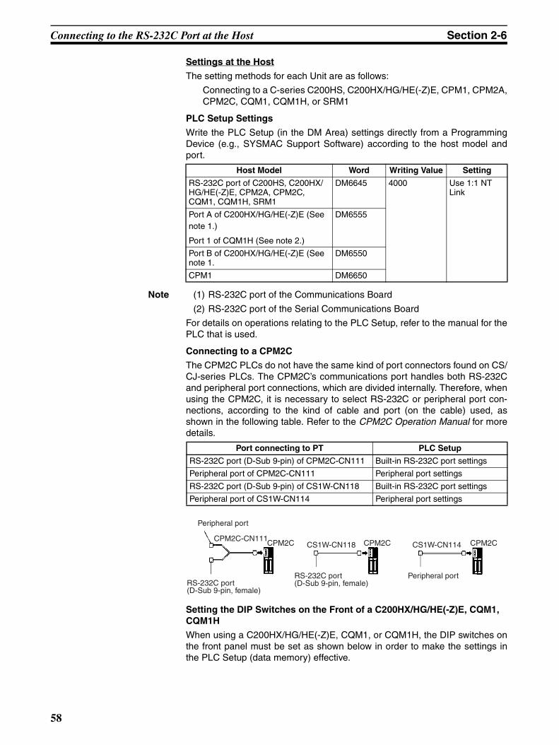
Connecting to the RS-232C Port at the Host Section 2-6
Settings at the Host
The setting methods for each Unit are as follows:
Connecting to a C-series C200HS, C200HX/HG/HE(-Z)E, CPM1, CPM2A,CPM2C, CQM1, CQM1H, or SRM1
PLC Setup Settings
Write the PLC Setup (in the DM Area) settings directly from a ProgrammingDevice (e.g., SYSMAC Support Software) according to the host model andport.
Note (1) RS-232C port of the Communications Board
(2) RS-232C port of the Serial Communications Board
For details on operations relating to the PLC Setup, refer to the manual for thePLC that is used.
Connecting to a CPM2C
The CPM2C PLCs do not have the same kind of port connectors found on CS/CJ-series PLCs. The CPM2C’s communications port handles both RS-232Cand peripheral port connections, which are divided internally. Therefore, whenusing the CPM2C, it is necessary to select RS-232C or peripheral port con-nections, according to the kind of cable and port (on the cable) used, asshown in the following table. Refer to the CPM2C Operation Manual for moredetails.
Setting the DIP Switches on the Front of a C200HX/HG/HE(-Z)E, CQM1, CQM1H
When using a C200HX/HG/HE(-Z)E, CQM1, or CQM1H, the DIP switches onthe front panel must be set as shown below in order to make the settings inthe PLC Setup (data memory) effective.
Host Model Word Writing Value Setting
RS-232C port of C200HS, C200HX/HG/HE(-Z)E, CPM2A, CPM2C, CQM1, CQM1H, SRM1
DM6645 4000 Use 1:1 NT Link
Port A of C200HX/HG/HE(-Z)E (See note 1.)
Port 1 of CQM1H (See note 2.)
DM6555
Port B of C200HX/HG/HE(-Z)E (See note 1.
DM6550
CPM1 DM6650
Port connecting to PT PLC Setup
RS-232C port (D-Sub 9-pin) of CPM2C-CN111 Built-in RS-232C port settings
Peripheral port of CPM2C-CN111 Peripheral port settings
RS-232C port (D-Sub 9-pin) of CS1W-CN118 Built-in RS-232C port settings
Peripheral port of CS1W-CN114 Peripheral port settings
Peripheral port
RS-232C port(D-Sub 9-pin, female)
CPM2C-CN111CPM2C
RS-232C port(D-Sub 9-pin, female)
CS1W-CN118 CPM2C
Peripheral port
CS1W-CN114 CPM2C
58

Connecting to the RS-232C Port at the Host Section 2-6
Setting the Switches of a CPM2A
When using a CPM2A, the switches on the front panel must be set as shownbelow in order to make the PLC Setup settings effective.
Setting the Switches of a CPM2C
When using a CPM2C, the switches on the front panel must be set as shownbelow in order to make the PLC Setup settings effective.
Setting the Switches on an RS-232C Adapter
When using a CPM1-CIF01 RS-232C Adapter, set the mode switch as shownin the following diagram.
C200HX/HG/HE(-Z)E CQM1 CQM1H
RS-232C port communications condition setting Set pin 5 to OFF to make the settings made in PLC Setup effective.
Set the Communications switch to OFF (down position).
• Connecting PT to peripheral port• Connecting PT to built-in RS-232C port
SW1: OFFSW2: ON
• Connecting PT to built-in RS-232C port(A Programming Console is connected to the peripheral port.)
SW1: OFFSW2: OFF
The settings for SW1 and SW2 depend upon the usage of the peripheral port and RS-232C port.
(A device that requires non-standard communications settings is connected to the peripheral port.)
CPM1-CIF01
Set the mode setting switch to NT (lower position).
59
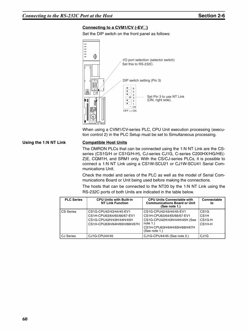
Connecting to the RS-232C Port at the Host Section 2-6
Connecting to a CVM1/CV (-EV@)
Set the DIP switch on the front panel as follows:
When using a CVM1/CV-series PLC, CPU Unit execution processing (execu-tion control 2) in the PLC Setup must be set to Simultaneous processing.
Using the 1:N NT Link Compatible Host Units
The OMRON PLCs that can be connected using the 1:N NT Link are the CS-series (CS1G/H or CS1G/H-H), CJ-series CJ1G, C-series C200HX/HG/HE(-Z)E, CQM1H, and SRM1 only. With the CS/CJ-series PLCs, it is possible toconnect a 1:N NT Link using a CS1W-SCU21 or CJ1W-SCU41 Serial Com-munications Unit.
Check the model and series of the PLC as well as the model of Serial Com-munications Board or Unit being used before making the connections.
The hosts that can be connected to the NT20 by the 1:N NT Link using theRS-232C ports of both Units are indicated in the table below.
OFF ↔ ON
123456
ON
I/O port selection (selector switch)Set this to RS-232C.
Set Pin 3 to use NT Link (ON, right side).
DIP switch setting (Pin 3)
PLC Series CPU Units with Built-inNT Link Function
CPU Units Connectable with Communications Board or Unit
(See note 1.)
Connectable to
CS Series CS1G-CPU42/43/44/45-EV1CS1H-CPU63/64/65/66/67-EV1CS1G-CPU42H/43H/44H/45HCS1H-CPU63H/64H/65H/66H/67H
CS1G-CPU42/43/44/45-EV1CS1H-CPU63/64/65/66/67-EV1CS1G-CPU42H/43H/44H/45H (See note 1.)CS1H-CPU63H/64H/65H/66H/67H (See note 1.)
CS1GCS1HCS1G-HCS1H-H
CJ Series CJ1G-CPU44/45 CJ1G-CPU44/45 (See note 2.) CJ1G
60

Connecting to the RS-232C Port at the Host Section 2-6
Note (1) A CS1W-SCB21 or CS1W-SCB41 Serial Communications Board orCS1W-SCU21 Serial Communications Unit is required.
(2) A CJ1W-SCU41 Serial Communications Unit is required.
(3) One of the following Communications Boards is required:C200HW-COM02/COM04/COM05/COM06 (-EV1)
(4) A CQM1H-SCB41 Serial Communications Board is required.
(5) The -V1 versions of CS-series PLCs and CJ-series PLCs support thehigh-speed 1:N NT Link as well as the standard 1:N NT Link. Further-more, the high-speed 1:N NT Link can be used in earlier versions of CS-series PLCs by installing a new version of Serial Communications Boardor Unit. For details, refer to Using the High-speed 1:N NT Links(page 65).
Settings at the Host
The Settings required for each Unit are described below.
Connecting a C200HX/HG/HE(-Z)E, CQM1H, or SRM1
PLC Setup Settings
Write the PLC Setup (in the DM Area) settings directly from a ProgrammingDevice (e.g., SYSMAC Support Software) according to the host model andport.
Note (1) RS-232C port on the Communications Board
(2) RS-232C port on the Serial Communications Board
C Series C200HE-CPU42-(Z)E C200HE-CPU32-(Z)E (See note 3.)C200HE-CPU42-(Z)E (See note 3.)
C200HE (-Z)E
C200HG-CPU43-(Z)EC200HG-CPU63-(Z)E
C200HG-CPU33-(Z)E (See note 3.)C200HG-CPU43-(Z)E (See note 3.)C200HG-CPU53-(Z)E (See note 3.)C200HG-CPU63-(Z)E (See note 3.)
C200HG (-Z)E
C200HX-CPU44-(Z)EC200HX-CPU64-(Z)EC200HX-CPU65-ZEC200HX-CPU85-ZE
C200HX-CPU34-(Z)E (See note 3.)C200HX-CPU44-(Z)E (See note 3.)C200HX-CPU54-(Z)E (See note 3.)C200HX-CPU64-(Z)E (See note 3.)C200HX-CPU65-ZE (See note 3.)C200HX-CPU85-ZE (See note 3.)
C200HX (-Z)E
--- CQM1H-CPU51 (See note 4.)CQM1H-CPU61 (See note 4.)
CQM1H
CompoBus/S Master Control Unit
SRM1-C02-V2 --- SRM1
PLC Series CPU Units with Built-inNT Link Function
CPU Units Connectable with Communications Board or Unit
(See note 1.)
Connectable to
Connection to Word Writing Value
Setting
C200HX/HG/HE(-Z)E, SRM1Built-in RS-232C port
DM6645 5@00 Use 1:N NT Link@ = largest unit number of the connected PTs (1 to 7) (See note 3.)
C200HX/HG/HE(-Z)E
Communications Board port A (See note 1.)
CQM1H port 1 (See note 2.)
DM6555
C200HX/HG/HE(-Z)ECommunications Board port B (See note 1.)
DM6550
61

Connecting to the RS-232C Port at the Host Section 2-6
(3) When using a C200HE (-Z)E, the maximum PT unit number is 3.
Refer to the PLC’s operation manual for details on changing PLC Setup set-tings.
Setting the DIP Switches of a C200HX/HG/HE(-Z)E
When using a C200HX/HG/HE(-Z)E, the DIP switches on the front panel mustbe set as shown below in order to make the settings in the PLC Setup (in theDM Area) effective.
Connecting to CS/CJ-series CPU Units
CS-series CPU Unit: CS1G/H-CPU@@-E(V1), CS1G/H-CPU@@H
CJ-series CPU Unit: CJ1G-CPU@@
PLC Setup
When connecting to a CS/CJ-series CPU Unit, set the following communica-tions conditions for the PLC Setup, according to the communications port tobe used.
When using the built-in RS-232C port of a CS1G/H, CS1G/H-H, or CJ1G
Note Set any value between 0000 and 0009 Hex for the communications baud rate.The same baud rate will be used regardless of the value as long as it isbetween 0000 and 0009 Hex.
When using the peripheral port of a CS1G/H, CS1G/H-H, or CJ1G
Note Set any value between 0000 and 0009 Hex for the communications baud rate.The same baud rate will be used regardless of the value as long as it isbetween 0000 and 0009 Hex.
When connecting PTs with model numbers 0 and 2 to 5 to the built-in RS-232C port, for example, set CIO 160 to 8200 Hex, CIO 161 to 0000 Hex andset CIO166 to 0005 Hex.
Word Value Settings
CIO 160 8200 1:N NT Link mode
CIO 161 0000 to 0009 (See note.)
Communications baud rate (standard)
CIO 166 000@ @ = The largest model number of the con-nected PT (0 – 7)
RS-232C port communications condition setting Set pin 5 to OFF to make the settings made in PLC Setup effective.
Word Value Settings
CIO 144 8200 1:N NT Link mode
CIO 145 0000 to 0009 (See note.)
Communications baud rate (standard)
CIO 150 000@ @ = The largest model number of the con-nected PT (0 – 7)
62
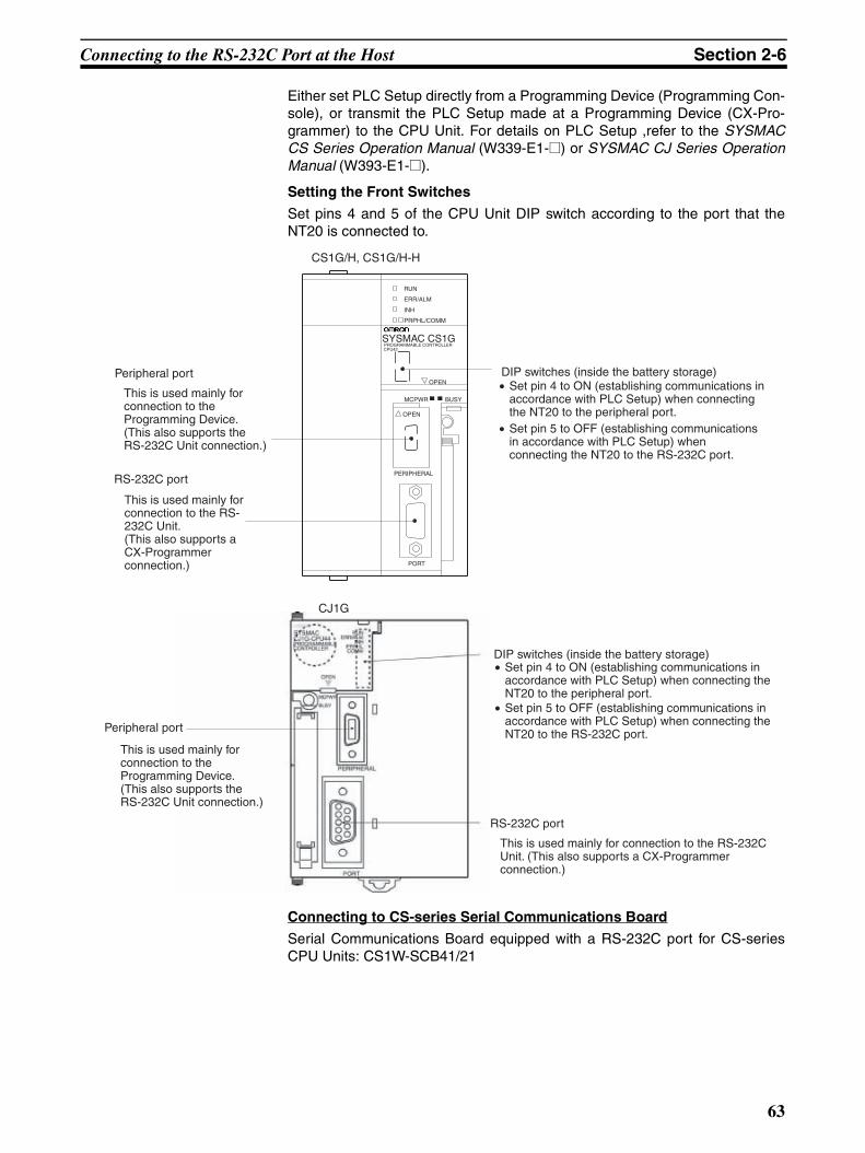
Connecting to the RS-232C Port at the Host Section 2-6
Either set PLC Setup directly from a Programming Device (Programming Con-sole), or transmit the PLC Setup made at a Programming Device (CX-Pro-grammer) to the CPU Unit. For details on PLC Setup ,refer to the SYSMACCS Series Operation Manual (W339-E1-@) or SYSMAC CJ Series OperationManual (W393-E1-@).
Setting the Front Switches
Set pins 4 and 5 of the CPU Unit DIP switch according to the port that theNT20 is connected to.
Connecting to CS-series Serial Communications Board
Serial Communications Board equipped with a RS-232C port for CS-seriesCPU Units: CS1W-SCB41/21
Peripheral port
RS-232C port
DIP switches (inside the battery storage)
SYSMAC CS1GPROGRAMMABLE CONTROLLER CPU42
OPEN
OPEN
PERIPHERAL
PORT
BUSY
RUN
ERR/ALM
INH
PRPHL/COMM
MCPWR
CS1G/H, CS1G/H-H
CJ1G
DIP switches (inside the battery storage)
Peripheral port
RS-232C port
This is used mainly for connection to the Programming Device. (This also supports the RS-232C Unit connection.)
This is used mainly for connection to the RS-232C Unit. (This also supports a CX-Programmer connection.)
This is used mainly for connection to the Programming Device. (This also supports the RS-232C Unit connection.)
This is used mainly for connection to the RS-232C Unit. (This also supports a CX-Programmer connection.)
• Set pin 4 to ON (establishing communications in accordance with PLC Setup) when connecting the NT20 to the peripheral port.
• Set pin 5 to OFF (establishing communications in accordance with PLC Setup) when connecting the NT20 to the RS-232C port.
• Set pin 4 to ON (establishing communications in accordance with PLC Setup) when connecting the NT20 to the peripheral port.
• Set pin 5 to OFF (establishing communications in accordance with PLC Setup) when connecting the NT20 to the RS-232C port.
63
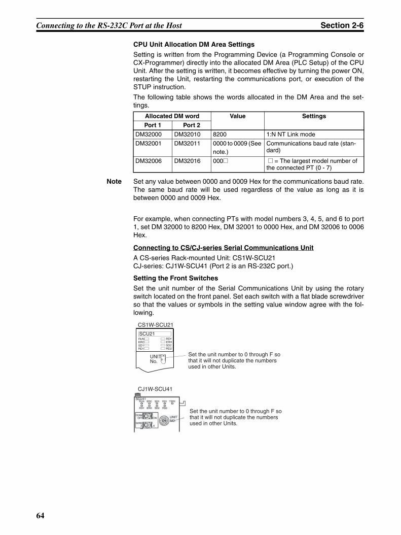
Connecting to the RS-232C Port at the Host Section 2-6
CPU Unit Allocation DM Area Settings
Setting is written from the Programming Device (a Programming Console orCX-Programmer) directly into the allocated DM Area (PLC Setup) of the CPUUnit. After the setting is written, it becomes effective by turning the power ON,restarting the Unit, restarting the communications port, or execution of theSTUP instruction.
The following table shows the words allocated in the DM Area and the set-tings.
Note Set any value between 0000 and 0009 Hex for the communications baud rate.The same baud rate will be used regardless of the value as long as it isbetween 0000 and 0009 Hex.
For example, when connecting PTs with model numbers 3, 4, 5, and 6 to port1, set DM 32000 to 8200 Hex, DM 32001 to 0000 Hex, and DM 32006 to 0006Hex.
Connecting to CS/CJ-series Serial Communications Unit
A CS-series Rack-mounted Unit: CS1W-SCU21CJ-series: CJ1W-SCU41 (Port 2 is an RS-232C port.)
Setting the Front Switches
Set the unit number of the Serial Communications Unit by using the rotaryswitch located on the front panel. Set each switch with a flat blade screwdriverso that the values or symbols in the setting value window agree with the fol-lowing.
Allocated DM word Value Settings
Port 1 Port 2
DM32000 DM32010 8200 1:N NT Link mode
DM32001 DM32011 0000 to 0009 (See note.)
Communications baud rate (stan-dard)
DM32006 DM32016 000@ @ = The largest model number of the connected PT (0 - 7)
SCU21RUN ERC SD1 RD1
RDYERHSD2RD2
No.FEDCBA98765
43210
UNIT
CS1W-SCU21
CJ1W-SCU41
Set the unit number to 0 through F so that it will not duplicate the numbers used in other Units.
Set the unit number to 0 through F so that it will not duplicate the numbers used in other Units.
64

Connecting to the RS-232C Port at the Host Section 2-6
Allocation DM Area Settings for CPU Unit
Setting is written from the Programming Device (a Programming Console orCX-Programmer) directly into the allocated DM Area (PLC Setup) of the CPUUnit. After the setting is written, it becomes effective by turning the power ON,restarting the Unit, restarting the communications port, or execution of theSTUP instruction.The following table shows the words allocated in the DM Area and the set-tings.
m = DM30000 + (100 × unit number)
Note Set any value between 0000 and 0009 Hex for the communications baud rate.The same baud rate will be used regardless of the value as long as it isbetween 0000 and 0009 Hex.
Using the High-speed 1:N NT Links
Compatible Host Units
Only the -V1 versions of the CS1-series CS1G/H, CS1-H-series CS1G/H-H,and CJ-series CJ1G PLCs support the high-speed 1:N NT Links directly.Other CS/CJ-series PLCs can use the high-speed 1:N NT Links indirectlythrough a CS1W-SCU21 or CJ1W-SCU41 Serial Communications Unit. (If aSerial Communications Unit is used, even CS1-series Units without the “-V1”suffix can be connected via high-speed 1:N NT Links.)
Be sure to check the model number of the PLC and Serial CommunicationsBoard/Unit before trying to establish the high-speed 1:N NT Links.
The following table shows which CS1-series PLCs can be connected to anNT20 with the high-speed 1:N NT Links.
Note (1) The direct high-speed 1:N NT Link connection is not supported by CS1-series CPU Units without the -V1 suffix.
(2) A CS1W-SCB21 or CS1W-SCB41 Serial Communications Board orCS1W-SCU21 Serial Communications Unit is required.
(3) A CJ1W-SCU41 Serial Communications Unit is required.
Settings at the Host
The Settings required for each Unit are described below.
Allocated DM word Value Settings
Port 1 Port 2
m m+10 8200 1:N NT Link mode
m+1 m+11 0000 to 0009 (See note.)
Communications baud rate (stan-dard)
m+6 m+16 000@ @ = The largest model number of the connected PT (0 - 7)
PLC model CPU Units with Built-inNT Link Function
CPU Units Connectable only through a Serial Communications Board or Unit
Connectable models
CS Series CS1G-CPU42/43/44/45-EV1 (See note 1.)CS1H-CPU63/64/65/66/67-EV1 (See note 1.)
CS1G-CPU42H/43H/44H/45H (See note 1.)CS1H-CPU63H/64H/65H/66H/67H (See note 1.)
CS1G-CPU42/43/44/45-E(V1) (See note 2.)
CS1H-CPU63/64/65/66/67-E(V1) (See note 2.)CS1G-CPU42H/43H/44H/45H (See note 2.)CS1H-CPU63H/64H/65H/66H/67H (See note 2.)
CS1GCS1H
CS1G-HCS1H-H
CJ Series CJ1G-CPU44/45 CJ1G-CPU44/45 (See note 3.) CJ1G
65

Connecting to the RS-232C Port at the Host Section 2-6
Connecting CS/CJ-series CPU Units
CS-series CPU Unit model: CS1G/H-CPU@@-EV1, CS1G/H-CPU@@HCJ-series CPU Unit model: CJ1G-CPU@@
PLC Setup
When connecting to a CS/CJ-series CPU Unit, set the following communica-tions conditions for the PLC Setup, according to the communications port tobe used.
When using the built-in RS-232C port of a CS1G/H, CS1G/H-H, or CJ1G
When using the peripheral port of a CS1G/H, CS1G/H-H, or CJ1G
When connecting PTs with model numbers 0, 2, 3, 4, and 5 to the built-in RS-232C port, for example, set CIO 160 to 8200 Hex, CIO 161 to 000A Hex, andCIO166 to 0005 Hex.
Either set PLC Setup directly from a Programming Device (Programming Con-sole), or transmit the PLC Setup made at a Programming Device (CX-Pro-grammer) to the CPU Unit.For details on PLC Setup, refer to the SYSMAC CS Series Operation Manual(W339-E1-@) or SYSMAC CJ Series Operation Manual (W393-E1-@).
Note When using the CX-Programmer to set the high-speed 1:N NT Link, set thecommunications baud rate to 115,200 bps.
Setting the Front Switches
Set pins 4 and 5 of the CPU Unit DIP switch according to the port that theNT20 is connected to.
Word Value Settings
160 8200 1:N NT Link mode
161 000A Communications baud rate (high-speed)
166 000@ @ = The largest model number of the con-nected PT (0 - 7)
Word Value Settings
144 8200 1:N NT Link mode
145 000A Communications baud rate (high-speed)
150 000@ @ = The largest model number of the con-nected PT (0 - 7)
66
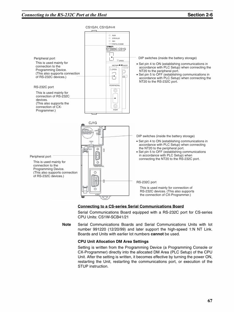
Connecting to the RS-232C Port at the Host Section 2-6
Connecting to a CS-series Serial Communications Board
Serial Communications Board equipped with a RS-232C port for CS-seriesCPU Units: CS1W-SCB41/21
Note Serial Communications Boards and Serial Communications Units with lotnumber 991220 (12/20/99) and later support the high-speed 1:N NT Link.Boards and Units with earlier lot numbers cannot be used.
CPU Unit Allocation DM Area Settings
Setting is written from the Programming Device (a Programming Console orCX-Programmer) directly into the allocated DM Area (PLC Setup) of the CPUUnit. After the setting is written, it becomes effective by turning the power ON,restarting the Unit, restarting the communications port, or execution of theSTUP instruction.
Peripheral port
RS-232C port
DIP switches (inside the battery storage)
SYSMAC CS1GPROGRAMMABLE CONTROLLER CPU42
OPEN
OPEN
PERIPHERAL
PORT
BUSY
RUN
ERR/ALM
INH
PRPHL/COMM
MCPWR
CS1G/H, CS1G/H-H
DIP switches (inside the battery storage)
Peripheral port
RS-232C port
CJ1G
This is used mainly for connection to the Programming Device. (This also supports connection of RS-232C devices.)
This is used mainly for connection of RS-232C devices. (This also supports the connection of CX-Programmer.)
This is used mainly for connection to the Programming Device. (This also supports connection of RS-232C devices.)
This is used mainly for connection of RS-232C devices. (This also supports the connection of CX-Programmer.)
• Set pin 4 to ON (establishing communications in accordance with PLC Setup) when connecting the NT20 to the peripheral port.
• Set pin 5 to OFF (establishing communications in accordance with PLC Setup) when connecting the NT20 to the RS-232C port.
• Set pin 4 to ON (establishing communications in accordance with PLC Setup) when connecting the NT20 to the peripheral port.
• Set pin 5 to OFF (establishing communications in accordance with PLC Setup) when connecting the NT20 to the RS-232C port.
67
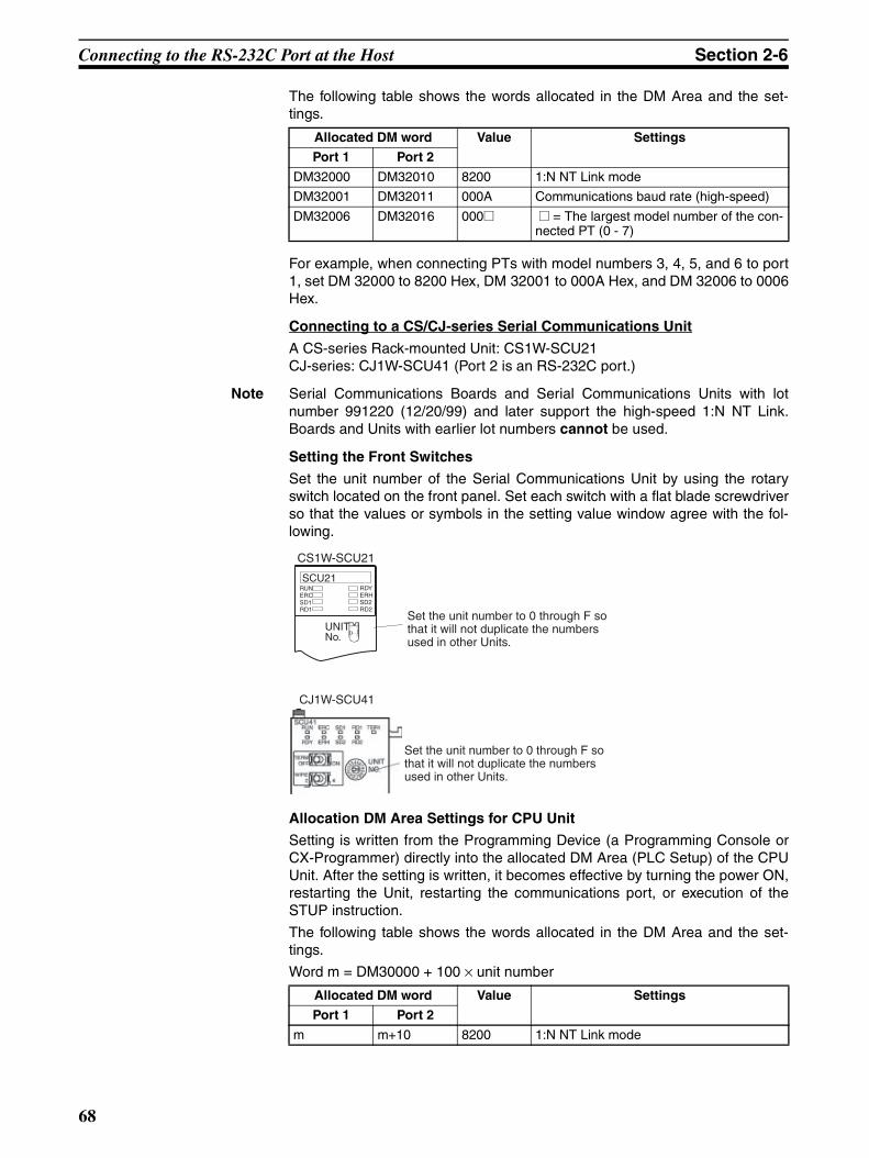
Connecting to the RS-232C Port at the Host Section 2-6
The following table shows the words allocated in the DM Area and the set-tings.
For example, when connecting PTs with model numbers 3, 4, 5, and 6 to port1, set DM 32000 to 8200 Hex, DM 32001 to 000A Hex, and DM 32006 to 0006Hex.
Connecting to a CS/CJ-series Serial Communications Unit
A CS-series Rack-mounted Unit: CS1W-SCU21CJ-series: CJ1W-SCU41 (Port 2 is an RS-232C port.)
Note Serial Communications Boards and Serial Communications Units with lotnumber 991220 (12/20/99) and later support the high-speed 1:N NT Link.Boards and Units with earlier lot numbers cannot be used.
Setting the Front Switches
Set the unit number of the Serial Communications Unit by using the rotaryswitch located on the front panel. Set each switch with a flat blade screwdriverso that the values or symbols in the setting value window agree with the fol-lowing.
Allocation DM Area Settings for CPU Unit
Setting is written from the Programming Device (a Programming Console orCX-Programmer) directly into the allocated DM Area (PLC Setup) of the CPUUnit. After the setting is written, it becomes effective by turning the power ON,restarting the Unit, restarting the communications port, or execution of theSTUP instruction.
The following table shows the words allocated in the DM Area and the set-tings.
Word m = DM30000 + 100 × unit number
Allocated DM word Value Settings
Port 1 Port 2
DM32000 DM32010 8200 1:N NT Link mode
DM32001 DM32011 000A Communications baud rate (high-speed)
DM32006 DM32016 000@ @ = The largest model number of the con-nected PT (0 - 7)
Allocated DM word Value Settings
Port 1 Port 2
m m+10 8200 1:N NT Link mode
CS1W-SCU21
CJ1W-SCU41
SCU21RUN ERC SD1 RD1
RDYERHSD2RD2
No.FEDCBA98765
43210
UNITSet the unit number to 0 through F so that it will not duplicate the numbers used in other Units.
Set the unit number to 0 through F so that it will not duplicate the numbers used in other Units.
68
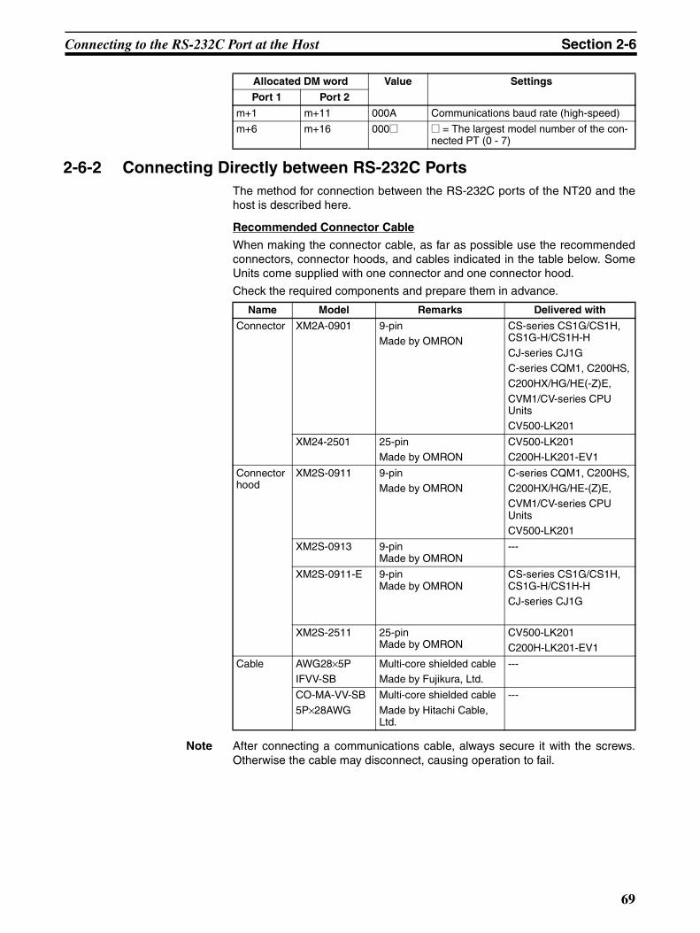
Connecting to the RS-232C Port at the Host Section 2-6
2-6-2 Connecting Directly between RS-232C PortsThe method for connection between the RS-232C ports of the NT20 and thehost is described here.
Recommended Connector Cable
When making the connector cable, as far as possible use the recommendedconnectors, connector hoods, and cables indicated in the table below. SomeUnits come supplied with one connector and one connector hood.
Check the required components and prepare them in advance.
Note After connecting a communications cable, always secure it with the screws.Otherwise the cable may disconnect, causing operation to fail.
m+1 m+11 000A Communications baud rate (high-speed)
m+6 m+16 000@ @ = The largest model number of the con-nected PT (0 - 7)
Allocated DM word Value Settings
Port 1 Port 2
Name Model Remarks Delivered with
Connector XM2A-0901 9-pinMade by OMRON
CS-series CS1G/CS1H, CS1G-H/CS1H-H
CJ-series CJ1GC-series CQM1, C200HS,C200HX/HG/HE(-Z)E,
CVM1/CV-series CPU UnitsCV500-LK201
XM24-2501 25-pinMade by OMRON
CV500-LK201C200H-LK201-EV1
Connector hood
XM2S-0911 9-pinMade by OMRON
C-series CQM1, C200HS,C200HX/HG/HE-(Z)E,CVM1/CV-series CPU UnitsCV500-LK201
XM2S-0913 9-pin Made by OMRON
---
XM2S-0911-E 9-pin Made by OMRON
CS-series CS1G/CS1H, CS1G-H/CS1H-HCJ-series CJ1G
XM2S-2511 25-pin Made by OMRON
CV500-LK201C200H-LK201-EV1
Cable AWG28×5PIFVV-SB
Multi-core shielded cableMade by Fujikura, Ltd.
---
CO-MA-VV-SB
5P×28AWG
Multi-core shielded cable
Made by Hitachi Cable, Ltd.
---
69
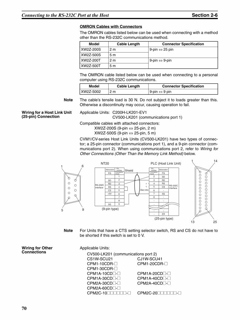
Connecting to the RS-232C Port at the Host Section 2-6
OMRON Cables with Connectors
The OMRON cables listed below can be used when connecting with a methodother than the RS-232C communications method.
The OMRON cable listed below can be used when connecting to a personalcomputer using RS-232C communications.
Note The cable’s tensile load is 30 N. Do not subject it to loads greater than this.Otherwise a discontinuity may occur, causing operation to fail.
Wiring for a Host Link Unit (25-pin) Connection
Applicable Units: C200H-LK201-EV1CV500-LK201 (communications port 1)
Compatible cables with attached connectors:XW2Z-200S (9-pin ⇔ 25-pin, 2 m)XW2Z-500S (9-pin ⇔ 25-pin, 5 m)
CVM1/CV-series Host Link Units (CV500-LK201) have two types of connec-tor; a 25-pin connector (communications port 1), and a 9-pin connector (com-munications port 2). When using communications port 2, refer to Wiring forOther Connections (Other Than the Memory Link Method) below.
Note For Units that have a CTS setting selector switch, RS and CS do not have tobe shorted if this switch is set to 0 V.
Wiring for Other Connections
Applicable Units:
CV500-LK201 (communications port 2)CS1W-SCU21 CJ1W-SCU41CPM1-10CDR-@ CPM1-20CDR-@CPM1-30CDR-@CPM1A-10CD@-@ CPM1A-20CD@-@CPM1A-30CD@-@ CPM1A-40CD@-@CPM2A-30CD@-@ CPM2A-40CD@-@CPM2A-60CD@-@CPM2C-10@@@@@@-@ CPM2C-20@@@@@@-@
Model Cable Length Connector Specification
XW2Z-200S 2 m 9-pin ⇔ 25 pin
XW2Z-500S 5 m
XW2Z-200T 2 m 9-pin ⇔ 9-pin
XW2Z-500T 5 m
Model Cable Length Connector Specification
XW2Z-S002 2 m 9-pin ⇔ 9 pin
1 6
5 9
(See note.)
NT201 14
13 25
FG
+5V
CS
RS
RD
SD
5G
1
2
3
4
5
6
7
8
9
2
3
4
5
6
7
8
-
-
-
-
FG
5G
CS
RS
RD
SD
ER
-
-
-
-
-
PLC (Host Link Unit)
(25-pin type)
(9-pin type)
Abbreviation Shield
RS-232C interface
Pin number
Connector hood
AbbreviationPin number
Connector hood
RS-232C interface
70
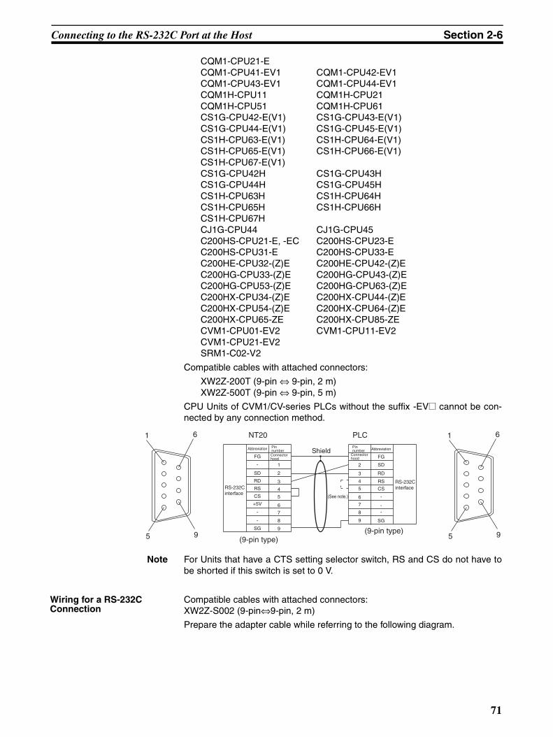
Connecting to the RS-232C Port at the Host Section 2-6
CQM1-CPU21-ECQM1-CPU41-EV1 CQM1-CPU42-EV1CQM1-CPU43-EV1 CQM1-CPU44-EV1CQM1H-CPU11 CQM1H-CPU21CQM1H-CPU51 CQM1H-CPU61CS1G-CPU42-E(V1) CS1G-CPU43-E(V1)CS1G-CPU44-E(V1) CS1G-CPU45-E(V1)CS1H-CPU63-E(V1) CS1H-CPU64-E(V1)CS1H-CPU65-E(V1) CS1H-CPU66-E(V1)CS1H-CPU67-E(V1)CS1G-CPU42H CS1G-CPU43HCS1G-CPU44H CS1G-CPU45HCS1H-CPU63H CS1H-CPU64HCS1H-CPU65H CS1H-CPU66HCS1H-CPU67HCJ1G-CPU44 CJ1G-CPU45C200HS-CPU21-E, -EC C200HS-CPU23-EC200HS-CPU31-E C200HS-CPU33-EC200HE-CPU32-(Z)E C200HE-CPU42-(Z)EC200HG-CPU33-(Z)E C200HG-CPU43-(Z)EC200HG-CPU53-(Z)E C200HG-CPU63-(Z)EC200HX-CPU34-(Z)E C200HX-CPU44-(Z)EC200HX-CPU54-(Z)E C200HX-CPU64-(Z)EC200HX-CPU65-ZE C200HX-CPU85-ZECVM1-CPU01-EV2 CVM1-CPU11-EV2CVM1-CPU21-EV2SRM1-C02-V2
Compatible cables with attached connectors:
XW2Z-200T (9-pin ⇔ 9-pin, 2 m)XW2Z-500T (9-pin ⇔ 9-pin, 5 m)
CPU Units of CVM1/CV-series PLCs without the suffix -EV@ cannot be con-nected by any connection method.
Note For Units that have a CTS setting selector switch, RS and CS do not have tobe shorted if this switch is set to 0 V.
Wiring for a RS-232C Connection
Compatible cables with attached connectors:XW2Z-S002 (9-pin⇔9-pin, 2 m)
Prepare the adapter cable while referring to the following diagram.
1 6
5 9
1 6
5 9
FG
+5V
CS
RS
RD
SD
SG
1
2
3
4
5
6
7
8
9
2
3
4
5
6
7
8
9
-
-
-
FG
-
CS
RS
RD
SD
SG
--
NT20 PLC
(9-pin type)
Shield
(9-pin type)
Abbreviation Pin numberConnector hood
RS-232C interface
AbbreviationPin number
Connector hood
RS-232C interface
(See note.)
71
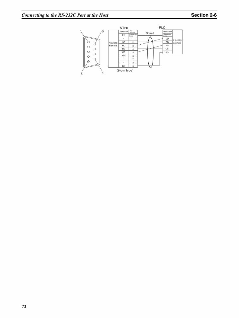
Connecting to the RS-232C Port at the Host Section 2-6
(9-pin type)
Shield1 6
5 9
NT20 PLC
FG
+5V
CS
RS
RD
SD
SG
1
2
3
4
5
6
7
8
9
-
-
-
CS
RS
RD
SD
SG
Abbreviation Pin numberConnector hood
RS-232C interface
Abbreviation
Connector hood
RS-232C interface
72
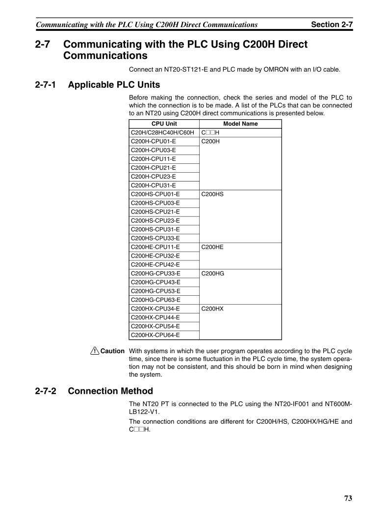
Communicating with the PLC Using C200H Direct Communications Section 2-7
2-7 Communicating with the PLC Using C200H Direct Communications
Connect an NT20-ST121-E and PLC made by OMRON with an I/O cable.
2-7-1 Applicable PLC UnitsBefore making the connection, check the series and model of the PLC towhich the connection is to be made. A list of the PLCs that can be connectedto an NT20 using C200H direct communications is presented below.
!Caution With systems in which the user program operates according to the PLC cycletime, since there is some fluctuation in the PLC cycle time, the system opera-tion may not be consistent, and this should be born in mind when designingthe system.
2-7-2 Connection MethodThe NT20 PT is connected to the PLC using the NT20-IF001 and NT600M-LB122-V1.
The connection conditions are different for C200H/HS, C200HX/HG/HE andC@@H.
CPU Unit Model Name
C20H/C28HC40H/C60H C@@H
C200H-CPU01-E C200H
C200H-CPU03-E
C200H-CPU11-E
C200H-CPU21-E
C200H-CPU23-E
C200H-CPU31-E
C200HS-CPU01-E C200HS
C200HS-CPU03-E
C200HS-CPU21-E
C200HS-CPU23-E
C200HS-CPU31-E
C200HS-CPU33-E
C200HE-CPU11-E C200HE
C200HE-CPU32-E
C200HE-CPU42-E
C200HG-CPU33-E C200HG
C200HG-CPU43-E
C200HG-CPU53-E
C200HG-CPU63-E
C200HX-CPU34-E C200HX
C200HX-CPU44-E
C200HX-CPU54-E
C200HX-CPU64-E
73
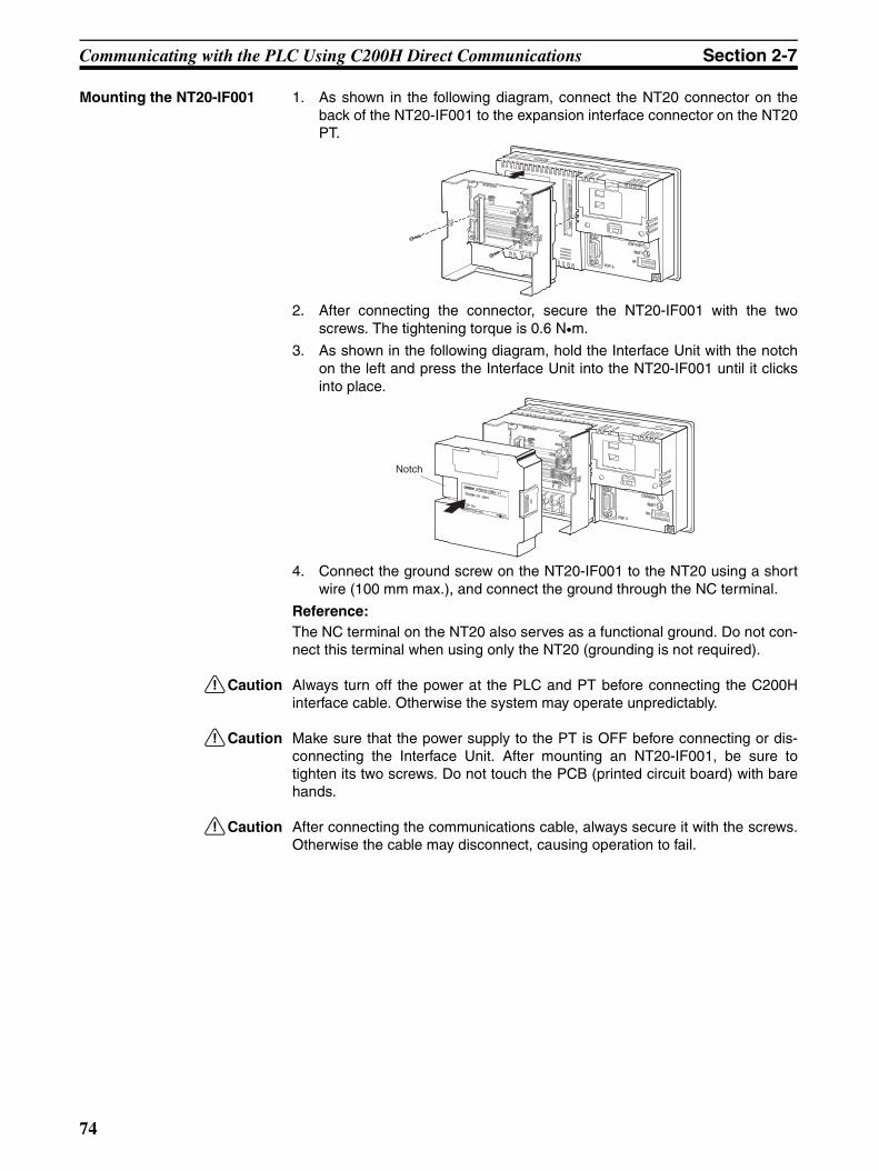
Communicating with the PLC Using C200H Direct Communications Section 2-7
Mounting the NT20-IF001 1. As shown in the following diagram, connect the NT20 connector on theback of the NT20-IF001 to the expansion interface connector on the NT20PT.
2. After connecting the connector, secure the NT20-IF001 with the twoscrews. The tightening torque is 0.6 N•m.
3. As shown in the following diagram, hold the Interface Unit with the notchon the left and press the Interface Unit into the NT20-IF001 until it clicksinto place.
4. Connect the ground screw on the NT20-IF001 to the NT20 using a shortwire (100 mm max.), and connect the ground through the NC terminal.
Reference:The NC terminal on the NT20 also serves as a functional ground. Do not con-nect this terminal when using only the NT20 (grounding is not required).
!Caution Always turn off the power at the PLC and PT before connecting the C200Hinterface cable. Otherwise the system may operate unpredictably.
!Caution Make sure that the power supply to the PT is OFF before connecting or dis-connecting the Interface Unit. After mounting an NT20-IF001, be sure totighten its two screws. Do not touch the PCB (printed circuit board) with barehands.
!Caution After connecting the communications cable, always secure it with the screws.Otherwise the cable may disconnect, causing operation to fail.
Notch
74

Communicating with the PLC Using C200H Direct Communications Section 2-7
I/O Connecting Cable
Use the following models of I/O Connecting Cable.
Note The C200H interface connector of NT20M-CNP@@@ has beendownsized.
!Caution Keep the total length of I/O cables used within 12 m (6 m for C@@H).
!Caution The cable's tensile load is 30 N. Do not subject it to loads greater than this.Otherwise a discontinuity may occur, causing operation to fail.
Reference:
If a C200H-CN@@@ or C20H-CN@@@ is used as the I/O Connecting Cable,the connector will project beyond the bottom face of the NT20.
If the I/O cable is passed through a hole or other opening, the diameter of thehole or opening must be at least 53 mmφ. Removing the top cover reducesthis requirement to 33 mmφ or larger. During installation, this cover must bereplaced before securing the PT.
Connection to C200H/C200HS and C200HX/HG/HE
Connect the CPU Rack or Expansion I/O Rack with an I/O cable. The follow-ing restrictions apply when making this connection.
• A maximum of one CPU Rack and one Expansion I/O Rack can be con-nected. Connection to two Expansion I/O Racks is not possible.
• Connection to a Remote Rack is not possible.
Model Cable Length (L)
For connecting C200H/HS/HE/HG/HX C200H-CN311 30 cm
NT20M-CNP711C200H-CN711
70 cm
NT20M-CNP221C200H-CN221
2 m
NT20M-CNP521C200H-CN521
5 m
NT20M-CNP131
C200H-CN131
10 m
For connecting C@@H C20H-CN312 30 cm
NT20M-CNP712C20H-CN712
70 cm
NT20M-CNP222C20H-CN222
2 m
75
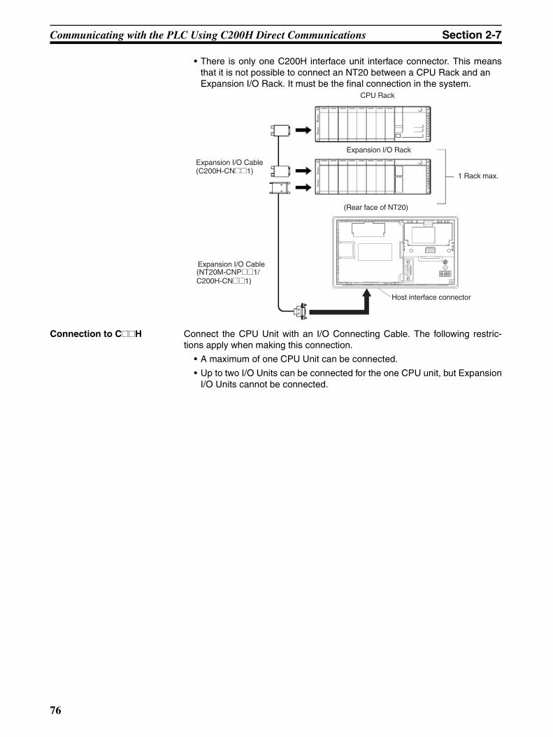
Communicating with the PLC Using C200H Direct Communications Section 2-7
• There is only one C200H interface unit interface connector. This meansthat it is not possible to connect an NT20 between a CPU Rack and an Expansion I/O Rack. It must be the final connection in the system.
Connection to C@@H Connect the CPU Unit with an I/O Connecting Cable. The following restric-tions apply when making this connection.
• A maximum of one CPU Unit can be connected.
• Up to two I/O Units can be connected for the one CPU unit, but ExpansionI/O Units cannot be connected.
CPU Rack
Expansion I/O Cable(C200H-CN@@1)
1 Rack max.
Expansion I/O Cable(NT20M-CNP@@1/ C200H-CN@@1)
Expansion I/O Rack
(Rear face of NT20)
Host interface connector
76
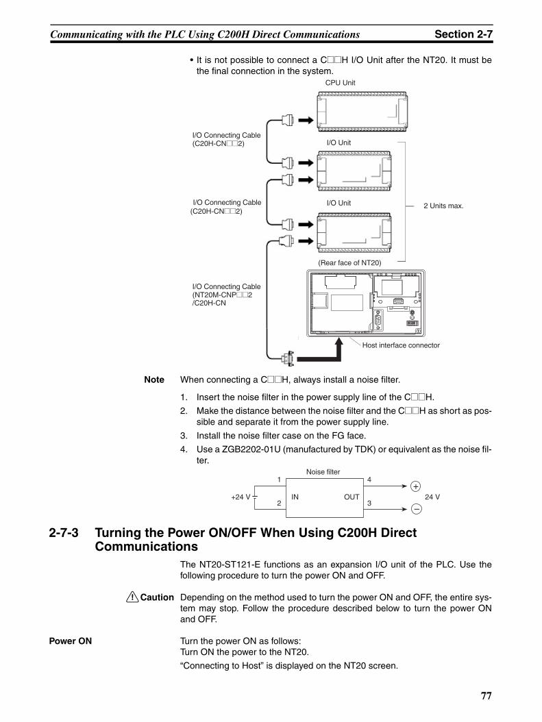
Communicating with the PLC Using C200H Direct Communications Section 2-7
• It is not possible to connect a C@@H I/O Unit after the NT20. It must bethe final connection in the system.
Note When connecting a C@@H, always install a noise filter.
1. Insert the noise filter in the power supply line of the C@@H.
2. Make the distance between the noise filter and the C@@H as short as pos-sible and separate it from the power supply line.
3. Install the noise filter case on the FG face.
4. Use a ZGB2202-01U (manufactured by TDK) or equivalent as the noise fil-ter.
2-7-3 Turning the Power ON/OFF When Using C200H Direct Communications
The NT20-ST121-E functions as an expansion I/O unit of the PLC. Use thefollowing procedure to turn the power ON and OFF.
!Caution Depending on the method used to turn the power ON and OFF, the entire sys-tem may stop. Follow the procedure described below to turn the power ONand OFF.
Power ON Turn the power ON as follows:Turn ON the power to the NT20.
“Connecting to Host” is displayed on the NT20 screen.
I/O Connecting Cable(C20H-CN@@2)
CPU Unit
I/O Connecting Cable(NT20M-CNP@@2/C20H-CN
I/O Connecting Cable(C20H-CN@@2)
2 Units max.
I/O Unit
I/O Unit
(Rear face of NT20)
Host interface connector
Noise filter1
2
4
3+24 V IN OUT 24 V
+
–
77

Communicating with the PLC Using C200H Direct Communications Section 2-7
↓Turn ON the power to the PLC.
After “Connecting to Host” has been displayed for approximately 1 second,normal operation starts.
Note (1) If the power to the PLC is turned ON first, the CPU Unit of the PLC is sub-jected to a system reset, making operations such as programming con-sole impossible. Then, when the power to the NT20 is turned ON,“Connecting to Host” is displayed on the NT20 screen for approximately1 second, after which normal operation starts.
(2) If the I/O Connecting Cable is disconnected during system operation, an I/O bus error occurs at the PLC and operation stops. If this happens, con-nect the I/O Connecting Cable and cancel the error.
Power OFF Turn the power OFF as follows:
Turn OFF the power supplies to the PLC and NT20 simultaneously.
The next time the power is turned ON, the NT20 displays the screen that wasdisplayed when the power was turned OFF.
Note If the power to the NT20 is turned OFF first, the CPU Unit of the PLC is sub-jected to a system reset, making operations such as programming consoleimpossible.
Turn OFF the system temporarily before replacing the NT20 (when a faultoccurs, for example). If the power to the NT20 only is turned OFF, the systemstops immediately and this could cause an accident or damage machinery.
78
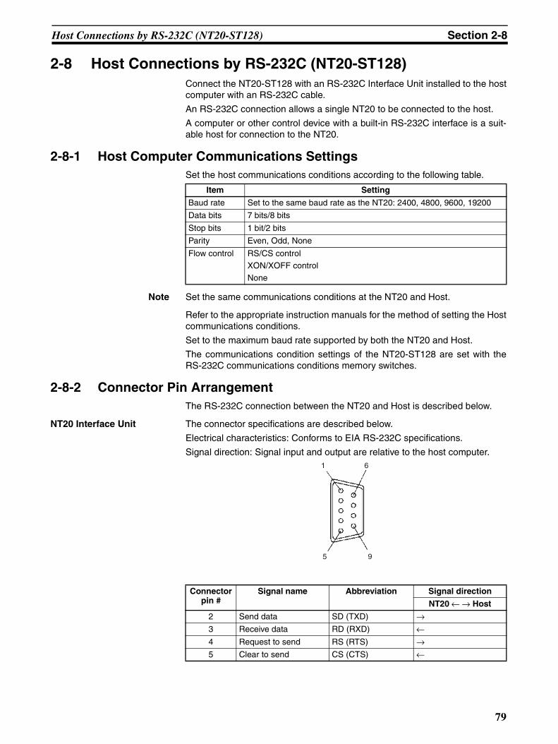
Host Connections by RS-232C (NT20-ST128) Section 2-8
2-8 Host Connections by RS-232C (NT20-ST128)Connect the NT20-ST128 with an RS-232C Interface Unit installed to the hostcomputer with an RS-232C cable.
An RS-232C connection allows a single NT20 to be connected to the host.
A computer or other control device with a built-in RS-232C interface is a suit-able host for connection to the NT20.
2-8-1 Host Computer Communications SettingsSet the host communications conditions according to the following table.
Note Set the same communications conditions at the NT20 and Host.
Refer to the appropriate instruction manuals for the method of setting the Hostcommunications conditions.
Set to the maximum baud rate supported by both the NT20 and Host.
The communications condition settings of the NT20-ST128 are set with theRS-232C communications conditions memory switches.
2-8-2 Connector Pin ArrangementThe RS-232C connection between the NT20 and Host is described below.
NT20 Interface Unit The connector specifications are described below.
Electrical characteristics: Conforms to EIA RS-232C specifications.
Signal direction: Signal input and output are relative to the host computer.
Item Setting
Baud rate Set to the same baud rate as the NT20: 2400, 4800, 9600, 19200
Data bits 7 bits/8 bits
Stop bits 1 bit/2 bits
Parity Even, Odd, None
Flow control RS/CS controlXON/XOFF control
None
Connector pin #
Signal name Abbreviation Signal direction
NT20 ← → Host
2 Send data SD (TXD) →3 Receive data RD (RXD) ←4 Request to send RS (RTS) →5 Clear to send CS (CTS) ←
1
5
6
9
79
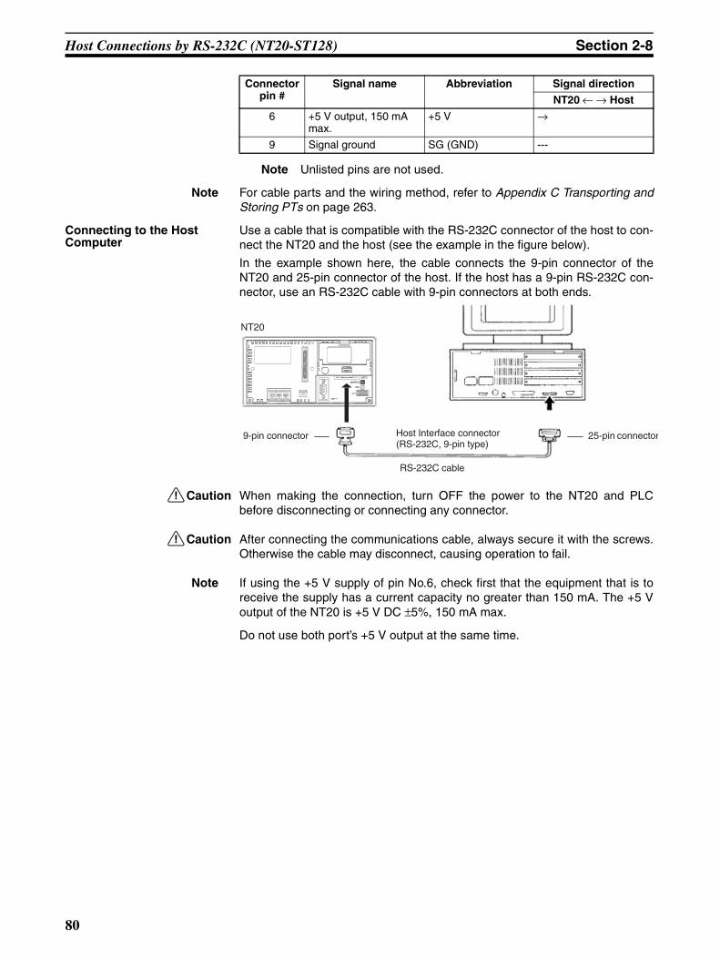
Host Connections by RS-232C (NT20-ST128) Section 2-8
Note Unlisted pins are not used.
Note For cable parts and the wiring method, refer to Appendix C Transporting andStoring PTs on page 263.
Connecting to the Host Computer
Use a cable that is compatible with the RS-232C connector of the host to con-nect the NT20 and the host (see the example in the figure below).
In the example shown here, the cable connects the 9-pin connector of theNT20 and 25-pin connector of the host. If the host has a 9-pin RS-232C con-nector, use an RS-232C cable with 9-pin connectors at both ends.
!Caution When making the connection, turn OFF the power to the NT20 and PLCbefore disconnecting or connecting any connector.
!Caution After connecting the communications cable, always secure it with the screws.Otherwise the cable may disconnect, causing operation to fail.
Note If using the +5 V supply of pin No.6, check first that the equipment that is toreceive the supply has a current capacity no greater than 150 mA. The +5 Voutput of the NT20 is +5 V DC ±5%, 150 mA max.
Do not use both port’s +5 V output at the same time.
6 +5 V output, 150 mA max.
+5 V →
9 Signal ground SG (GND) ---
Connector pin #
Signal name Abbreviation Signal direction
NT20 ← → Host
NT20
25-pin connectorHost Interface connector(RS-232C, 9-pin type)
9-pin connector
RS-232C cable
80
SECTION 3System Menu Operation
This section describes the operation of the System Menu focusing on the procedure to start up the NT20. Functions whichwill be convenient to use the NT20 and those which are useful for the system maintenance are also explained here.
3-1 Operation Flow by the System Menu . . . . . . . . . . . . . . . . . . . . . . . . . . . . . . . 82
3-2 Starting the NT20 . . . . . . . . . . . . . . . . . . . . . . . . . . . . . . . . . . . . . . . . . . . . . . 83
3-2-1 Changing the System Settings or Screen Data . . . . . . . . . . . . . . . . . 83
3-3 Operation Modes and the System Menu . . . . . . . . . . . . . . . . . . . . . . . . . . . . . 84
3-3-1 System Menu and the Operation Modes. . . . . . . . . . . . . . . . . . . . . . 84
3-3-2 Menu Tree. . . . . . . . . . . . . . . . . . . . . . . . . . . . . . . . . . . . . . . . . . . . . 84
3-3-3 Operations with the System Menu . . . . . . . . . . . . . . . . . . . . . . . . . . 86
3-4 Initializing Memory . . . . . . . . . . . . . . . . . . . . . . . . . . . . . . . . . . . . . . . . . . . . 88
3-4-1 Initialization by Using the System Menu . . . . . . . . . . . . . . . . . . . . . 88
3-4-2 Initialization by Using the DIP Switch (Forced Initialization). . . . . 90
3-5 Setting the Conditions of Communications with the Host by Using the Memory Switches . . . . . . . . . . . . . . . . . . . . . . . . . . . . . . . . . . . . . . . . . . . 91
3-5-1 Selecting the Host Communications Method . . . . . . . . . . . . . . . . . . 93
3-5-2 Selecting the Host Communications Port . . . . . . . . . . . . . . . . . . . . . 94
3-5-3 Selecting the Host Link Communications Speed . . . . . . . . . . . . . . . 95
3-5-4 Selecting the NT Link (1:N) Communications Speed . . . . . . . . . . . 96
3-5-5 Selecting Unit Numbers . . . . . . . . . . . . . . . . . . . . . . . . . . . . . . . . . . 97
3-5-6 Selecting the Automatic Reset Function. . . . . . . . . . . . . . . . . . . . . . 98
3-5-7 Setting RS–232C Communications Conditions (NT20-ST128). . . . 99
3-6 Registering the Screen Data . . . . . . . . . . . . . . . . . . . . . . . . . . . . . . . . . . . . . . 102
3-7 Starting the Operation . . . . . . . . . . . . . . . . . . . . . . . . . . . . . . . . . . . . . . . . . . . 105
3-8 Various System Settings . . . . . . . . . . . . . . . . . . . . . . . . . . . . . . . . . . . . . . . . . 106
3-8-1 Setting the Key Press Sound. . . . . . . . . . . . . . . . . . . . . . . . . . . . . . . 106
3-8-2 Using the Buzzer. . . . . . . . . . . . . . . . . . . . . . . . . . . . . . . . . . . . . . . . 107
3-8-3 Backlight OFF Function . . . . . . . . . . . . . . . . . . . . . . . . . . . . . . . . . . 109
3-8-4 Language Function . . . . . . . . . . . . . . . . . . . . . . . . . . . . . . . . . . . . . . 110
3-8-5 Support Tool Mode Setting (NT20-ST121-E) . . . . . . . . . . . . . . . . . 111
3-8-6 Lamp Bit Control (NT20-ST128). . . . . . . . . . . . . . . . . . . . . . . . . . . 112
3-9 System Maintenance . . . . . . . . . . . . . . . . . . . . . . . . . . . . . . . . . . . . . . . . . . . . 115
3-9-1 I/O Check . . . . . . . . . . . . . . . . . . . . . . . . . . . . . . . . . . . . . . . . . . . . . 115
3-9-2 Checking the PT Setting . . . . . . . . . . . . . . . . . . . . . . . . . . . . . . . . . . 122
3-9-3 Checking the NT20 DIP Switch Settings . . . . . . . . . . . . . . . . . . . . . 124
3-10 Transferring the System Program . . . . . . . . . . . . . . . . . . . . . . . . . . . . . . . . . . 126
3-11 Transferring the Resource Data. . . . . . . . . . . . . . . . . . . . . . . . . . . . . . . . . . . . 129
81

Operation Flow by the System Menu Section 3-1
3-1 Operation Flow by the System MenuFollow the procedure below when using the NT20 for the first time or whenchanging the system.
Create the Screen Data Create the screen data to be displayed on the NT20 by using the SupportTool.
For the screen data creation, refer to the “NT Support Tool for Windows Oper-ation Manual” (V061-E1-@).
Start Up the NT20 (Display the System Menu.) (page 84)Turn ON the power to the NT20.
When no screen data has been registered, the “SYSTEM MENU” will be dis-played. If the NT20 enters the RUN mode, press appropriate touch switchesto display the System Menu.
Initializing Memory (page 88)Select a System Menu and initialize the NT20 unit memory.
Memory Switch Settings (page 91)Select the System Menu and make settings such as the communications con-ditions for communications with the Host by setting the memory switches.
Registering the Screen Data (page 102)Connect the Support Tool to the NT20 and transfer the screen data from theSupport Tool to the NT20.
For the connection of the Support Tool, refer to 2-4 Connecting the NT Sup-port Tool on page 35.
Starting the Operation (page 105)
Connect to the PLC/Host and start the operation.
System Maintenance (page 115)If an error has occurred during operation, check the I/Os, settings, etc. refer-ring to this guide.
82
Starting the NT20 Section 3-2
3-2 Starting the NT20When the NT20 is started, it will enter the RUN mode if system settings andscreen data registration have been completed. If no screen data has beenregistered or the screen data are destroyed, the System Menu will be dis-played.
Before turning ON the power, check the following DIP switch settings on theNT20.
• SW2-3 “Switch to the System Menu enabled/disabled” is set to OFF(enabled).
• SW2-1 “Screen data forced initialize Yes/No” is set to No (ineffective).
For the DIP switch settings of the unit, refer to the 2-1-2 Operation Status DIPSwitch Settings (page 19).
3-2-1 Changing the System Settings or Screen DataFollow the procedure below to change the system settings or screen datacontents.
Note (1) Turn ON the power to the NT20.The NT20 will enter the RUN mode and the start-up screen will be dis-played. The start-up screen varies according to registered screen data.
(2) Press appropriate touch switches to display the System Menu, andchange system settings. For the method for calling the System Menu, re-fer to the 3-3-3 Operations with the System Menu on page 86.
(3) If the NT20 has failed to start up normally; an error message is displayedor no screen is displayed, memory needs to be initialized.For the memory initializing procedure, refer to 3-4 Initializing Memory onpage 88.
83
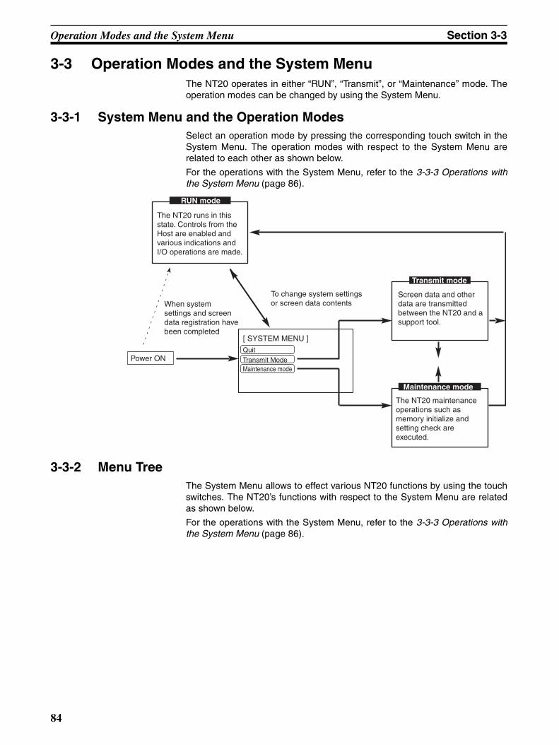
Operation Modes and the System Menu Section 3-3
3-3 Operation Modes and the System MenuThe NT20 operates in either “RUN”, “Transmit”, or “Maintenance” mode. Theoperation modes can be changed by using the System Menu.
3-3-1 System Menu and the Operation ModesSelect an operation mode by pressing the corresponding touch switch in theSystem Menu. The operation modes with respect to the System Menu arerelated to each other as shown below.
For the operations with the System Menu, refer to the 3-3-3 Operations withthe System Menu (page 86).
3-3-2 Menu TreeThe System Menu allows to effect various NT20 functions by using the touchswitches. The NT20’s functions with respect to the System Menu are relatedas shown below.
For the operations with the System Menu, refer to the 3-3-3 Operations withthe System Menu (page 86).
RUN mode
Transmit mode
Power ON
[ SYSTEM MENU ]
Quit
Transmit ModeMaintenance mode
Maintenance mode
Screen data and other data are transmitted between the NT20 and a support tool.
To change system settings or screen data contentsWhen system
settings and screen data registration have been completed
The NT20 runs in this state. Controls from the Host are enabled and various indications and I/O operations are made.
The NT20 maintenance operations such as memory initialize and setting check are executed.
84
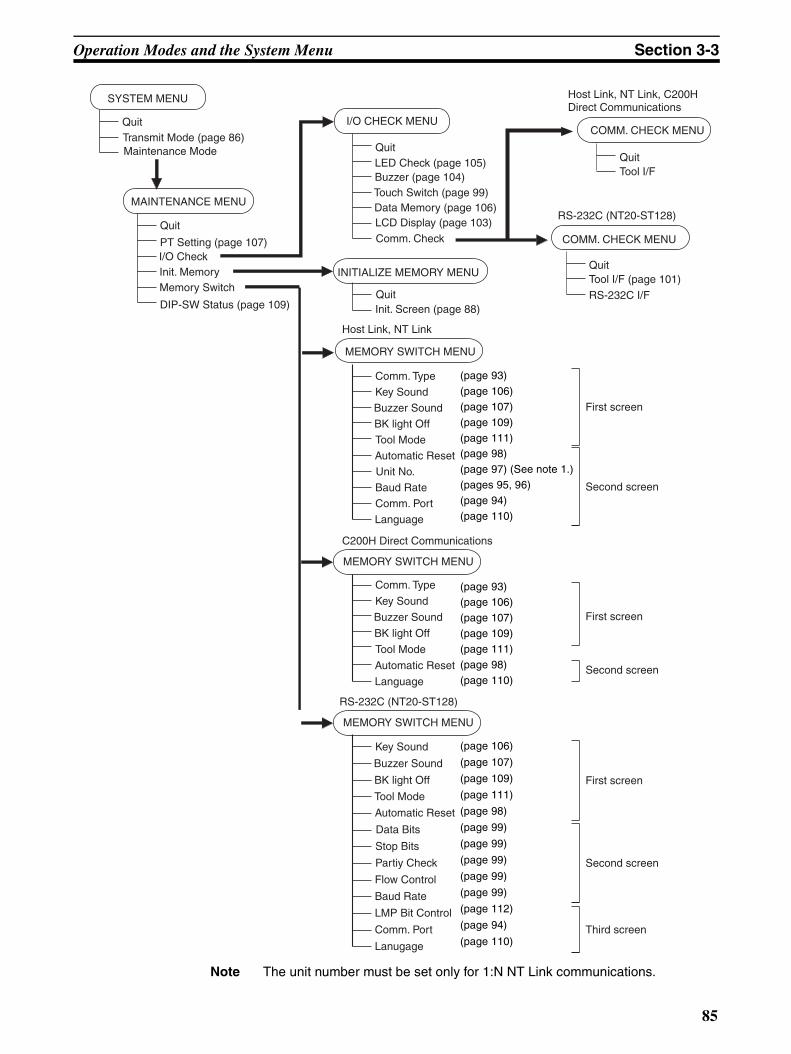
Operation Modes and the System Menu Section 3-3
Note The unit number must be set only for 1:N NT Link communications.
MAINTENANCE MENU
QuitTransmit Mode (page 86)Maintenance Mode
I/O CHECK MENU
INITIALIZE MEMORY MENU
MEMORY SWITCH MENU
SYSTEM MENU
COMM. CHECK MENUQuit
PT Setting (page 107)I/O CheckInit. MemoryMemory Switch
DIP-SW Status (page 109)
QuitLED Check (page 105)Buzzer (page 104)Touch Switch (page 99)Data Memory (page 106)LCD Display (page 103)
Comm. Check
QuitInit. Screen (page 88)
Comm. Type
Key Sound
Buzzer Sound
BK light Off
Tool Mode
Automatic Reset
Unit No.
Baud Rate
QuitTool I/F (page 101)
First screen
Second screen
COMM. CHECK MENU
QuitTool I/F
Host Link, NT Link, C200H Direct Communications
RS-232C I/F
Host Link, NT Link
MEMORY SWITCH MENU
C200H Direct Communications
Comm. Type
Key Sound
Buzzer Sound
BK light Off
Tool Mode
Automatic Reset
Language
First screen
Second screen
MEMORY SWITCH MENU
RS-232C (NT20-ST128)
Key Sound
Buzzer Sound
BK light Off
Automatic Reset
Data Bits
Partiy Check
Flow Control
First screen
Second screen
Baud Rate
LMP Bit Control
Lanugage
Third screen
RS-232C (NT20-ST128)
Stop Bits
Tool Mode
Comm. Port
Comm. Port
Language
(page 93)(page 106)(page 107)(page 109)(page 111)(page 98)(page 97) (See note 1.)(pages 95, 96)(page 94)(page 110)
(page 93)(page 106)(page 107)(page 109)(page 111)(page 98)(page 110)
(page 106)
(page 107)
(page 109)
(page 111)
(page 98)
(page 99)
(page 99)
(page 99)
(page 99)
(page 99)
(page 112)
(page 94)
(page 110)
85

Operation Modes and the System Menu Section 3-3
3-3-3 Operations with the System MenuThe following gives the procedure to call the System Menu, select the menuitems, and other operations with the System Menu.
Make sure that DIP SW2-3 “Switch to the System Menu enabled/disabled” isset to OFF (enabled). If the setting is ON (disabled), the System Menu will notbe displayed by following the procedure given below.
Displaying the System Menu
Press appropriate touch switches to display the System Menu as describedbelow. The “RUN” LED goes off when the System Menu is displayed.
The NT20 display screen has four touch switches to display the System Menuin the four corners (about 9 mm x 9 mm size). Press any two of these switchesat the same time to call the System Menu screen.
Note that the touch switches used to call the System Menu are not displayedon the screen. If a touch switch displayed in a corner is pressed first, the touchswitch will function and the System Menu will not be displayed. To success-fully call the System Menu, first press a corner where no touch key is dis-played, and then, press any other corner regardless of the presence of atouch key.
If a screen has the touch switches registered at all of the four corners, it isimpossible to call the System Menu from the screen.
A “system key” function can be assigned to a touch switch. Pressing the touchswitch so assigned on the screen can easily display the System Menu. For therelationship between the system key and the touch switch, refer to the 4-7-3System Key Functions (page 154).
RUN mode
[SYSTEM MENU]Quit
Transmit Mode
Maintenance mode
Press any two of these four corners at the same time.
86

Operation Modes and the System Menu Section 3-3
Selecting the Menu Items Press (touch) a menu item on the screen to select the item.
Menu items allow to make the ON/OFF selection or to call subsequent menuor screen.
Example 1
To call the “Maintenance mode menu” by pressing the “Maintenance Mode”on the System Menu screen:
System Menu Items The System Menu items and the functions are as given below.
Switching from the System Menu to the RUN Mode
The NT20 will exit the System Menu and switch to the RUN mode in the casesdescribed below.
• Selecting “Quit” in the System Menu.
• The screen (touch switches) is not pressed for over 10 seconds.
[ SYSTEM MENU ]
QuitTransmit ModeMaintenance Mode
Select “Maintenance Mode”.
[ MAINTENANCE MENU ]QuitPT SettingI/O Check
DIP-SW Status
Init. MemoryMemory Switch
Menu Item Function
Quit The System Menu screen is cleared and the NT20 will return to the RUN mode.
Transmit Mode The Transmit Mode screen will be displayed to allow the trans-mission of the screen data between the NT20 and the Support Tool. For the transmission of the screen data, refer to3-6 Regis-tering the Screen Data (page 102).
Maintenance Mode The MAINTENANCE MENU will be displayed to allow the main-tenance of the NT20 system.
87

Initializing Memory Section 3-4
3-4 Initializing MemoryIf the NT20 is used for the first time or if the screen data is ruined and theNT20 cannot be normally started, the memory needs to be initialized.
The memory initialization is required in the cases described below.
• When the NT20 is used for the first time or when an error message indi-cating that the screen data is ruined etc. when the NT20 is started.
Use the “Maintenance Mode” – “Init. Memory” in the System Menu.
• When the NT20 has made a buzzer sound and the screen has disap-peared during the start-up or operation.
Use the NT20 DIP SW2-1 “Screen data forced initialize Yes/No”.
When an error has occurred, the error messages such as “Screen data cor-rupted” will be displayed. For the error messages displayed on the screen,refer to 7-2 Responding to Displayed Error Messages.
Note Initializing the screen data memory will erase entire screen data registered inthe NT20. Make sure that there are backup copies of the screen data onfloppy disks before starting the initialization.
• Data of the NT20 to Be Initialized
Screen dataSystem memoryMemory tablesMark dataDirect information
3-4-1 Initialization by Using the System MenuInitialize the screen data memory by following the procedure given below.
[ SYSTEM MENU ]
QuitTransmit ModeMaintenance Mode
Select “Maintenance Mode”.
[ MAINTENANCE MENU ]QuitPT SettingI/O Check
DIP-SW Status
Init. MemoryMemory Switch
Select “Init. Memory”.
88
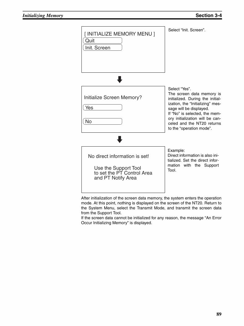
Initializing Memory Section 3-4
After initialization of the screen data memory, the system enters the operationmode. At this point, nothing is displayed on the screen of the NT20. Return tothe System Menu, select the Transmit Mode, and transmit the screen datafrom the Support Tool.If the screen data cannot be initialized for any reason, the message “An ErrorOccur Initializing Memory” is displayed.
[ INITIALIZE MEMORY MENU ]QuitInit. Screen
Select “Init. Screen”.
Initialize Screen Memory?
Yes
No
Select “Yes”.The screen data memory isinitialized. During the initial-ization, the “Initializing” mes-sage will be displayed.If “No” is selected, the mem-ory initialization will be can-celed and the NT20 returnsto the “operation mode”.
Use the Support Toolto set the PT Control Areaand PT Notify Area
No direct information is set!Example: Direct information is also ini-tialized. Set the direct infor-mation with the SupportTool.
89
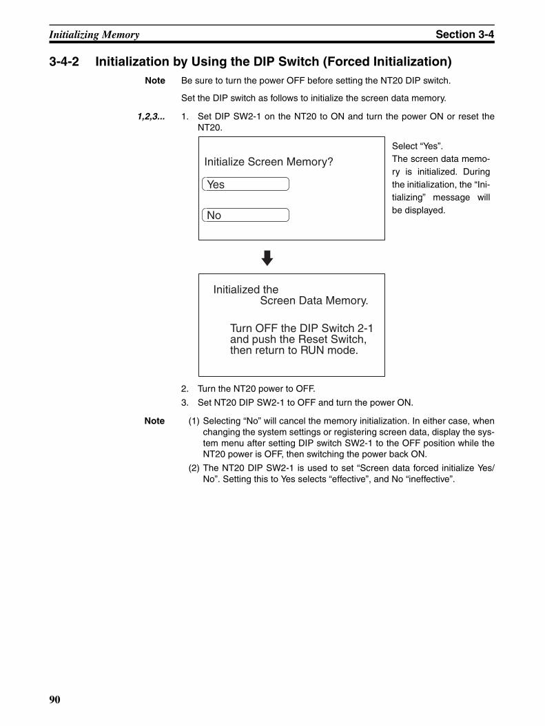
Initializing Memory Section 3-4
3-4-2 Initialization by Using the DIP Switch (Forced Initialization)Note Be sure to turn the power OFF before setting the NT20 DIP switch.
Set the DIP switch as follows to initialize the screen data memory.
1,2,3... 1. Set DIP SW2-1 on the NT20 to ON and turn the power ON or reset theNT20.
2. Turn the NT20 power to OFF.
3. Set NT20 DIP SW2-1 to OFF and turn the power ON.
Note (1) Selecting “No” will cancel the memory initialization. In either case, whenchanging the system settings or registering screen data, display the sys-tem menu after setting DIP switch SW2-1 to the OFF position while theNT20 power is OFF, then switching the power back ON.
(2) The NT20 DIP SW2-1 is used to set “Screen data forced initialize Yes/No”. Setting this to Yes selects “effective”, and No “ineffective”.
Initialize Screen Memory?
Yes
No
Select “Yes”.The screen data memo-ry is initialized. Duringthe initialization, the “Ini-tializing” message willbe displayed.
Turn OFF the DIP Switch 2-1and push the Reset Switch,then return to RUN mode.
Initialized the Screen Data Memory.
90

Setting the Conditions of Communications with the Host by Using the Memory Switches Section 3-5
3-5 Setting the Conditions of Communications with the Host by Using the Memory Switches
The communications between the NT20 and a PLC/Host are called the hostcommunications.
The NT20 PTs can be connected to the host using the following communica-tions methods.
NT20-ST121-E: Host Link or NT Link (both direct connections)
NT20-ST121-E + NT20-IF001 + NT600M-LB122-V1: C200H direct communications (direct connection)
NT20-ST128: RS-232C communications (command control)
With the NT20-ST121-E, the Host Link, 1:1 NT Link, or 1:N NT Link communi-cations method is set using a memory switch. Other settings, such as theband rate and automatic resetting of communications, are also set with mem-ory switches. This section describes the communications condition settingsusing the memory switches.
Memory Switches The NT20 has the memory areas used to store the PLC connection method,communications conditions, system settings, etc. which can be used as theswitches and called the “memory switches”. Since the memory switches usethe flash memory, the stored data can be held even when the power supply isturned OFF.
If the memory switch memory is corrupted for any reason, a message will bedisplayed when the operating mode is changed. Press the Write touch switchand initialize the memory.
Setting Functions and the Memory Switch Menu
The memory switches can be set easily by using the memory switch menu inthe System Menu.
The following settings can be made with the memory switches. Refer to thesubsequent pages and 3-8 Various System Settings for details on each set-ting and function.
• Host Link Method
• NT Link (1:1) Method
[ MEMORY SW MENU ] (1/2) QuitComm. Type
Key Sound Page
WRT& EXIT
Buzzer Sound
Bk light Off
Tool Mode
Host Link
OFF
OFF
None
NT20
[ MEMORY SW MENU ] (2/2)
Automatic Reset
Baud Rate
Comm. Port
Language
No
9600bps
Port B
English
Quit
Page
WRT& EXIT
[ MEMORY SW MENU ] (1/2) QuitComm. Type
Key Sound Page
WRT& EXIT
Buzzer Sound
Bk light Off
Tool Mode
NT Link
OFF
OFF
None
NT20
[ MEMORY SW MENU ] (2/2)
Automatic Reset
Comm. Port
Language
No
Port B
English
Quit
Page
WRT& EXIT
91
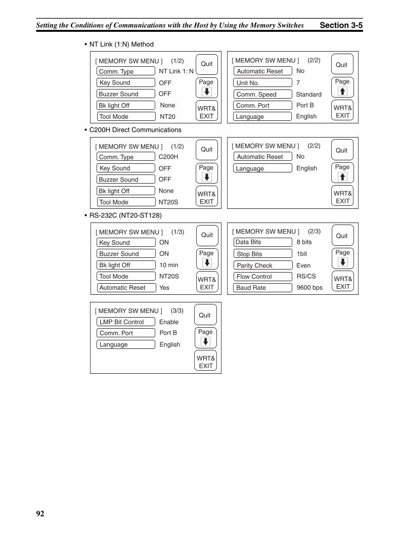
Setting the Conditions of Communications with the Host by Using the Memory Switches Section 3-5
• NT Link (1:N) Method
• C200H Direct Communications
• RS-232C (NT20-ST128)
[ MEMORY SW MENU ] (1/2) QuitComm. Type
Key Sound Page
WRT& EXIT
Buzzer Sound
Bk light Off
Tool Mode
NT Link 1: N
OFF
OFF
None
NT20
[ MEMORY SW MENU ] (2/2)
Automatic Reset
Unit No.
Comm. Speed
Comm. Port
No
7
Standard
Port B
Quit
Page
WRT& EXITLanguage English
[ MEMORY SW MENU ] (1/2) QuitComm. Type
Key Sound Page
WRT& EXIT
Buzzer Sound
Bk light Off
Tool Mode
C200H
OFF
OFF
None
NT20S
[ MEMORY SW MENU ] (2/2)
Automatic Reset No
English
Quit
Page
WRT& EXIT
Language
[ MEMORY SW MENU ] (1/3) Quit
Page
WRT& EXIT
[ MEMORY SW MENU ] (2/3)
Stop Bits
Parity Check
Flow Control
8 bits
1bit
Even
RS/CS
Quit
Page
WRT& EXITBaud Rate
Data Bits
9600 bps
(3/3)
LMP Bit Control EnableQuit
Page
WRT& EXIT
Key Sound
Buzzer Sound
Bk light Off
ON
ON
Tool Mode
Automatic Reset
10 min
NT20S
Yes
Comm. Port
Language
Port B
English
[ MEMORY SW MENU ]
92

Setting the Conditions of Communications with the Host by Using the Memory Switches Section 3-5
3-5-1 Selecting the Host Communications MethodThe NT20 can be connected to a PLC by the Host Link, the NT link, or theC200H Direct communications. Either link can be selected by setting the“Comm. Type” memory switch. The factory setting has been made to the“Host link”.
Select the host communications method by the menu operation from the Sys-tem Menu as described below.
To set and quit the menu, press the [WRT&EXIT] touch switch. To quit withoutsetting, press [Quit].
Note The communications method must be selected according to the method thatthe connecting PLC supports.
[ SYSTEM MENU ]
QuitTransmit ModeMaintenance Mode
Select “Maintenance Mode”.
[ MAINTENANCE MENU ]QuitPT SettingI/O Check
DIP-SW Status
Init. MemoryMemory Switch
Select “Memory Switch”.
Comm. TypeKey SoundBuzzer Sound
Host LinkOFF
Bk light OffTool Mode
OFFNoneNT20S
(1/2)Quit
[ MEMORY SW MENU ]
Page
WRT &
EXIT
Repeatedly pressing the“Comm. Type” touch switchcauses the setting to cyclethrough the options “Hostlink”, “NT link”, “NT Link1:N”, and “C200H” in thatorder.
93

Setting the Conditions of Communications with the Host by Using the Memory Switches Section 3-5
3-5-2 Selecting the Host Communications PortThere are two communications ports in NT20. Either of them can be set forcommunications. But Port A can be set to communications with either the host(Host link, NT link 1:1, NT link 1:N, RS-232C) or Support Tool and Port B canonly be set to communications with the host (Host link, NT link 1:1, NT link1:N, RS-232C).
Note The NT20 can not communicate with both two ports at one time.The factory setting has been made at “Port B”.Select the host communications port by the menu operation from the SystemMenu as described below. (e.g., Host Link)
To set and quit the menu, press the [WRT&EXIT] touch switch. To quit withoutsetting, press [Quit].
[ SYSTEM MENU ]
QuitTransmit ModeMaintenance Mode
Select “Maintenance Mode”.
[ MAINTENANCE MENU ]QuitPT SettingI/O Check
DIP-SW Status
Init. MemoryMemory Switch
Select “Memory Switch”.
Comm. TypeKey SoundBuzzer Sound
Host LinkOFF
Bk light OffTool Mode
OFFNoneNT20S
(1/2) Quit[ MEMORY SW MENU ]
Page
WRT &
EXIT
Select “Page”.
Automatic ResetBaud Rate
No9600bps
(2/2) Quit[ MEMORY SW MENU ]
Page
WRT &
EXIT
Comm. PortLanguage
Port BEnglish
Each time the “Comm.Port” touch switch ispressed, the setting optionalternates between “Port A”and “Port B”.
94

Setting the Conditions of Communications with the Host by Using the Memory Switches Section 3-5
3-5-3 Selecting the Host Link Communications SpeedWhen using the NT20 with the host link, the baud rate of the communicationswith the PLC can be set. Use the “Baud Rate” switch and select 9600 bps,19200 bps, 38400 bps, 57600 bps, or 115200 bps.The factory setting has been made at 9600 bps.Select the baud rate of the communications with the PLC by the menu opera-tion from the System Menu as described below.
To set and quit the menu, press the [WRT&EXIT] touch switch. To quit withoutsetting, press [Quit].
[ SYSTEM MENU ]
QuitTransmit ModeMaintenance Mode
Select “Maintenance Mode”.
[ MAINTENANCE MENU ]QuitPT SettingI/O Check
DIP-SW Status
Init. MemoryMemory Switch
Select “Memory Switch”.
Comm. TypeKey SoundBuzzer Sound
Host LinkOFF
Bk light OffTool Mode
OFFNoneNT20S
(1/2) Quit[ MEMORY SW MENU ]
Page
WRT &
EXIT
Select “Page”.If the host link is not select-ed, press the “Comm. Type” touch switch and se-lect “Host link”.
Automatic ResetBaud Rate
No9600bps
(2/2) Quit[ MEMORY SW MENU ]
Page
WRT &
EXIT
Comm. PortLanguage
Port BEnglish
Each time “Baud Rate” ispressed, the setting that isdisplayed will change.
95
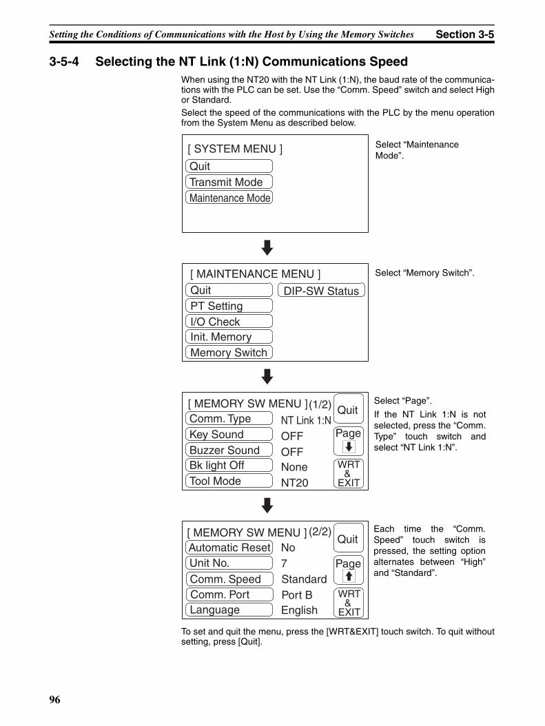
Setting the Conditions of Communications with the Host by Using the Memory Switches Section 3-5
3-5-4 Selecting the NT Link (1:N) Communications SpeedWhen using the NT20 with the NT Link (1:N), the baud rate of the communica-tions with the PLC can be set. Use the “Comm. Speed” switch and select Highor Standard.Select the speed of the communications with the PLC by the menu operationfrom the System Menu as described below.
To set and quit the menu, press the [WRT&EXIT] touch switch. To quit withoutsetting, press [Quit].
[ SYSTEM MENU ]
QuitTransmit ModeMaintenance Mode
Select “Maintenance Mode”.
[ MAINTENANCE MENU ]QuitPT SettingI/O Check
DIP-SW Status
Init. MemoryMemory Switch
Select “Memory Switch”.
Comm. TypeKey SoundBuzzer Sound
NT Link 1:NOFF
Bk light OffTool Mode
OFFNoneNT20
(1/2) Quit[ MEMORY SW MENU ]
Page
WRT &
EXIT
Select “Page”.
If the NT Link 1:N is notselected, press the “Comm.Type” touch switch andselect “NT Link 1:N”.
Automatic ResetUnit No.
No7
(2/2)Quit
[ MEMORY SW MENU ]
Page
WRT &
EXIT
Comm. SpeedComm. Port
StandardPort B
Language English
Each time the “Comm.Speed” touch switch ispressed, the setting optionalternates between “High”and “Standard”.
96

Setting the Conditions of Communications with the Host by Using the Memory Switches Section 3-5
3-5-5 Selecting Unit NumbersWhen using NT20 with the NT link (1:N) communications method, set unitnumbers.When using NT link (1:N), unit numbers are used to identify each of the multi-ple PTs connected to a single PLC port. Set a different unit number for eachof the PTs connected to the port.The unit numbers that can be set differ according to the type of host PLC asfollows.
C200HE: Unit Nos. 0 to 3
C200HG, C200HX: Unit Nos. 0 to 7
Set the unit numbers by following the menu operation from the System Menudescribed below.
[ SYSTEM MENU ]
QuitTransmit ModeMaintenance Mode
Select “Maintenance Mode”.
[ MAINTENANCE MENU ]QuitPT SettingI/O Check
DIP-SW Status
Init. MemoryMemory Switch
Select “Memory Switch”.
Comm. TypeKey SoundBuzzer Sound
NT Link 1:NOFF
Bk light OffTool Mode
OFFNone
(1/2) Quit[ MEMORY SW MENU ]
Page
WRT &
EXITNT20S
Press the “Comm Type”touch switch to select “NTlink (1:N)”.Select “Page”.
97

Setting the Conditions of Communications with the Host by Using the Memory Switches Section 3-5
To set and quit the menu, press the [WRT & EXIT] touch switch. To quit with-out setting, press [Quit]. The run mode will be established.
3-5-6 Selecting the Automatic Reset Function The “Automatic Reset” memory switch is used to set whether or not the com-munications are automatically reset after the occurrence of a communicationserror.
The factory setting has been made at “No”.
Select the baud rate of the communications with the PLC by the menu opera-tion from the System Menu as described below.
Automatic ResetUnit No.
No7
(2/2) Quit[ MEMORY SW MENU ]
Page
WRT &
EXIT
Comm. SpeedComm. Port
StandardPort B
Language English
Repeatedly pressing the “Unit No.” touch switch cycles through the numbers that can be set.
[ SYSTEM MENU ]
QuitTransmit ModeMaintenance Mode
Select “Maintenance Mode”.
[ MAINTENANCE MENU ]QuitPT SettingI/O Check
DIP-SW Status
Init. MemoryMemory Switch
Select “Memory Switch”.
Comm. TypeKey SoundBuzzer Sound
Host LinkOFF
Bk light OffTool Mode
OFFNone
(1/2) Quit[ MEMORY SW MENU ]
Page
WRT &
EXITNT20S
Select “Page”.
98
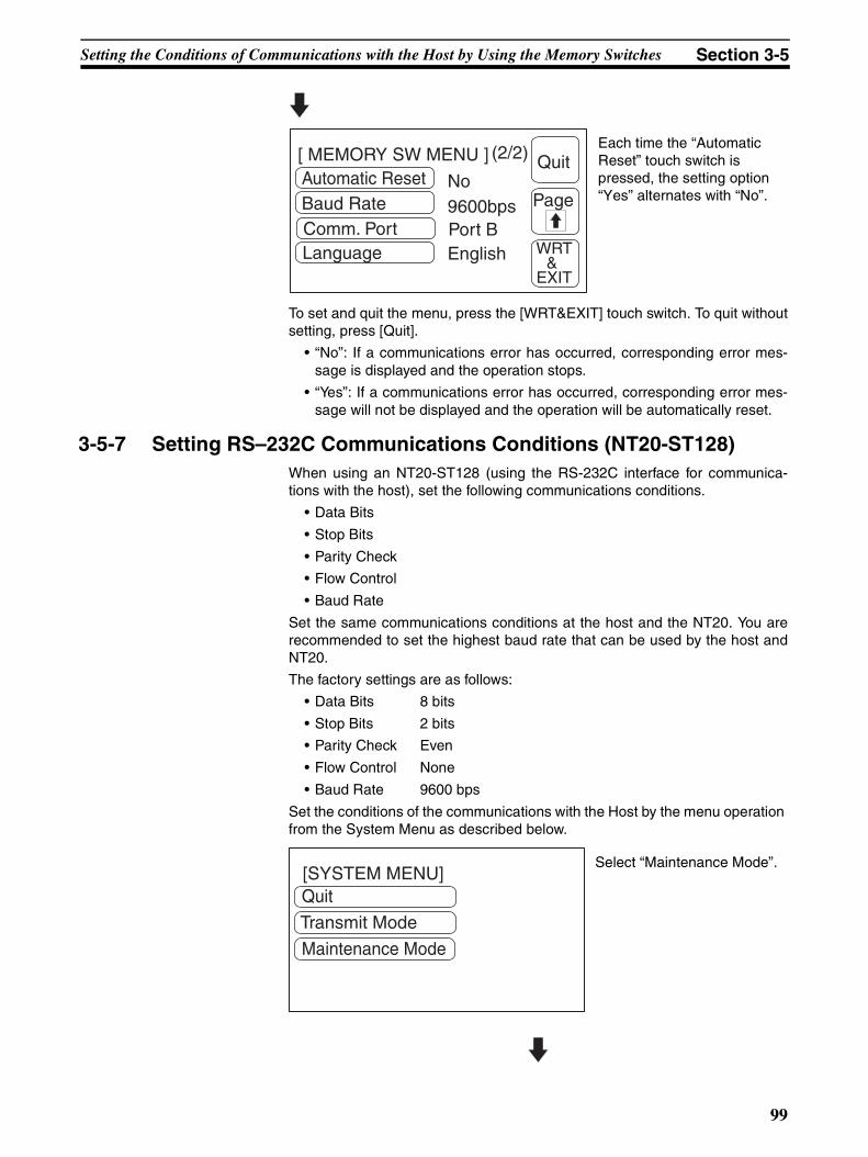
Setting the Conditions of Communications with the Host by Using the Memory Switches Section 3-5
To set and quit the menu, press the [WRT&EXIT] touch switch. To quit withoutsetting, press [Quit].
• “No”: If a communications error has occurred, corresponding error mes-sage is displayed and the operation stops.
• “Yes”: If a communications error has occurred, corresponding error mes-sage will not be displayed and the operation will be automatically reset.
3-5-7 Setting RS–232C Communications Conditions (NT20-ST128)When using an NT20-ST128 (using the RS-232C interface for communica-tions with the host), set the following communications conditions.
• Data Bits
• Stop Bits
• Parity Check
• Flow Control
• Baud Rate
Set the same communications conditions at the host and the NT20. You arerecommended to set the highest baud rate that can be used by the host andNT20.
The factory settings are as follows:
• Data Bits 8 bits
• Stop Bits 2 bits
• Parity Check Even
• Flow Control None
• Baud Rate 9600 bps
Set the conditions of the communications with the Host by the menu operation from the System Menu as described below.
Automatic ResetBaud Rate
No9600bps
(2/2) Quit[ MEMORY SW MENU ]
Page
WRT &
EXIT
Comm. Port Port BLanguage English
Each time the “Automatic Reset” touch switch is pressed, the setting option “Yes” alternates with “No”.
Quit
Transmit Mode
[SYSTEM MENU]
Maintenance Mode
Select “Maintenance Mode”.
99
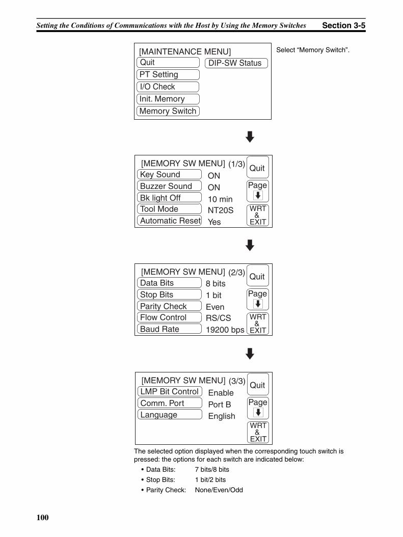
Setting the Conditions of Communications with the Host by Using the Memory Switches Section 3-5
The selected option displayed when the corresponding touch switch is pressed: the options for each switch are indicated below:
• Data Bits: 7 bits/8 bits
• Stop Bits: 1 bit/2 bits
• Parity Check: None/Even/Odd
Quit
PT Setting
[MAINTENANCE MENU]
I/O Check
Init. Memory
Memory Switch
DIP-SW Status
Select “Memory Switch”.
Key SoundBuzzer SoundBk light Off
ONON
Tool ModeAutomatic Reset
10 minNT20SYes
(1/3) Quit[MEMORY SW MENU]
Page
WRT &
EXIT
Data BitsStop BitsParity Check
8 bits1 bit
Flow ControlBaud Rate
EvenRS/CS19200 bps
(2/3) Quit[MEMORY SW MENU]
Page
WRT &
EXIT
LMP Bit ControlComm. PortLanguage
EnablePort BEnglish
(3/3) Quit[MEMORY SW MENU]
Page
WRT &
EXIT
100

Setting the Conditions of Communications with the Host by Using the Memory Switches Section 3-5
• Flow Control: None/RS/CS/XON/XOFF
• Baud Rate: 2400 bps/4800 bps/9600 bps/19200 bps
• LMP Bit Control: Enable/Disable
Note Use the same condition settings as set for the host. It is recommended thatthe highest baud rate possible is selected for both the host and the NT20.
For details on lamp bit control, refer to 3-8 Various System Settings on pagepage 106.
101
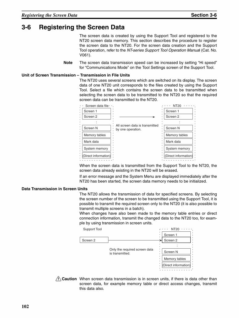
Registering the Screen Data Section 3-6
3-6 Registering the Screen DataThe screen data is created by using the Support Tool and registered to theNT20 screen data memory. This section describes the procedure to registerthe screen data to the NT20. For the screen data creation and the SupportTool operation, refer to the NT-series Support Tool Operation Manual (Cat. No.V061).
Note The screen data transmission speed can be increased by setting “Hi speed”for “Communications Mode” on the Tool Settings screen of the Support Tool.
Unit of Screen Transmission – Transmission in File UnitsThe NT20 uses several screens which are switched on its display. The screendata of one NT20 unit corresponds to the files created by using the SupportTool. Select a file which contains the screen data to be transmitted whenselecting the screen data to be transmitted to the NT20 so that the requiredscreen data can be transmitted to the NT20.
When the screen data is transmitted from the Support Tool to the NT20, thescreen data already existing in the NT20 will be erased.
If an error message and the System Menu are displayed immediately after theNT20 has been started, the screen data memory needs to be initialized.
Data Transmission in Screen UnitsThe NT20 allows the transmission of data for specified screens. By selectingthe screen number of the screen to be transmitted using the Support Tool, it ispossible to transmit the required screen only to the NT20 (it is also possible totransmit multiple screens in a batch).When changes have also been made to the memory table entries or directconnection information, transmit the changed data to the NT20 too, for exam-ple by using transmission in screen units.
!Caution When screen data transmission is in screen units, if there is data other thanscreen data, for example memory table or direct access changes, transmitthis data also.
Screen data file
Screen 1
Screen 2
Screen N
Memory tables
Mark data
System memory
(Direct information)
NT20
Screen 1
Screen 2
Screen N
Memory tables
Mark data
System memory
(Direct information)
: :All screen data is transmitted by one operation.
Support Tool
Screen 2
NT20
Screen 1
Screen 2
Screen N
Memory tables
(Direct information)
:Only the required screen data is transmitted.
102
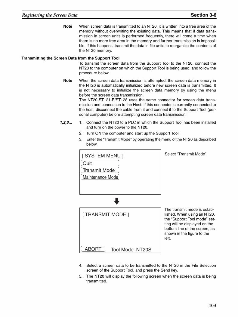
Registering the Screen Data Section 3-6
Note When screen data is transmitted to an NT20, it is written into a free area of thememory without overwriting the existing data. This means that if data trans-mission in screen units is performed frequently, there will come a time whenthere is no more free area in the memory and further transmission is impossi-ble. If this happens, transmit the data in file units to reorganize the contents ofthe NT20 memory.
Transmitting the Screen Data from the Support ToolTo transmit the screen data from the Support Tool to the NT20, connect theNT20 to the computer on which the Support Tool is being used, and follow theprocedure below.
Note When the screen data transmission is attempted, the screen data memory inthe NT20 is automatically initialized before new screen data is transmitted. Itis not necessary to initialize the screen data memory by using the menubefore the screen data transmission.The NT20-ST121-E/ST128 uses the same connector for screen data trans-mission and connection to the Host. If this connector is currently connected tothe host, disconnect the cable from it and connect it to the Support Tool (per-sonal computer) before attempting screen data transmission.
1,2,3... 1. Connect the NT20 to a PLC in which the Support Tool has been installedand turn on the power to the NT20.
2. Turn ON the computer and start up the Support Tool.
3. Enter the “Transmit Mode” by operating the menu of the NT20 as describedbelow.
4. Select a screen data to be transmitted to the NT20 in the File Selectionscreen of the Support Tool, and press the Send key.
5. The NT20 will display the following screen when the screen data is beingtransmitted.
[ SYSTEM MENU ]
QuitTransmit ModeMaintenance Mode
Select “Transmit Mode”.
ABORT
[ TRANSMIT MODE ]
Tool Mode NT20S
The transmit mode is estab-lished. When using an NT20, the “Support Tool mode” set-ting will be displayed on the bottom line of the screen, as shown in the figure to the left.
103
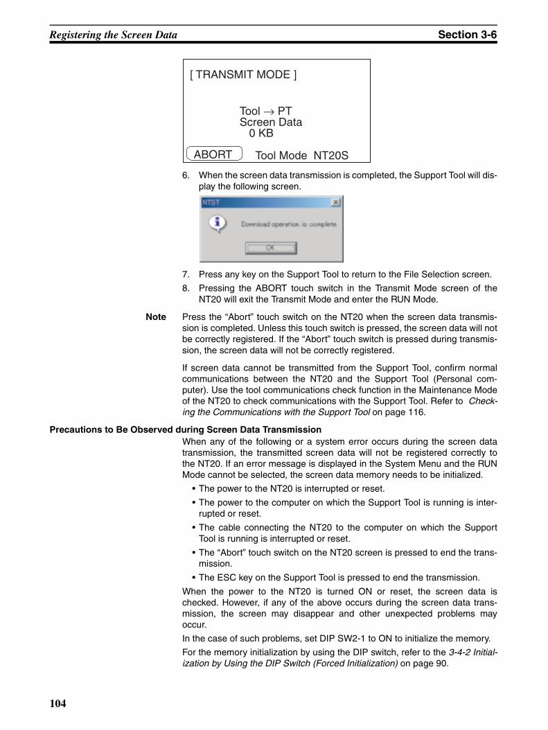
Registering the Screen Data Section 3-6
6. When the screen data transmission is completed, the Support Tool will dis-play the following screen.
7. Press any key on the Support Tool to return to the File Selection screen.
8. Pressing the ABORT touch switch in the Transmit Mode screen of theNT20 will exit the Transmit Mode and enter the RUN Mode.
Note Press the “Abort” touch switch on the NT20 when the screen data transmis-sion is completed. Unless this touch switch is pressed, the screen data will notbe correctly registered. If the “Abort” touch switch is pressed during transmis-sion, the screen data will not be correctly registered.
If screen data cannot be transmitted from the Support Tool, confirm normalcommunications between the NT20 and the Support Tool (Personal com-puter). Use the tool communications check function in the Maintenance Modeof the NT20 to check communications with the Support Tool. Refer to Check-ing the Communications with the Support Tool on page 116.
Precautions to Be Observed during Screen Data TransmissionWhen any of the following or a system error occurs during the screen datatransmission, the transmitted screen data will not be registered correctly tothe NT20. If an error message is displayed in the System Menu and the RUNMode cannot be selected, the screen data memory needs to be initialized.
• The power to the NT20 is interrupted or reset.
• The power to the computer on which the Support Tool is running is inter-rupted or reset.
• The cable connecting the NT20 to the computer on which the SupportTool is running is interrupted or reset.
• The “Abort” touch switch on the NT20 screen is pressed to end the trans-mission.
• The ESC key on the Support Tool is pressed to end the transmission.
When the power to the NT20 is turned ON or reset, the screen data ischecked. However, if any of the above occurs during the screen data trans-mission, the screen may disappear and other unexpected problems mayoccur.
In the case of such problems, set DIP SW2-1 to ON to initialize the memory.
For the memory initialization by using the DIP switch, refer to the 3-4-2 Initial-ization by Using the DIP Switch (Forced Initialization) on page 90.
ABORT
[ TRANSMIT MODE ]
Tool → PTScreen Data 0 KB
Tool Mode NT20S
104

Starting the Operation Section 3-7
3-7 Starting the OperationAfter completing the screen data transmission and setting the communica-tions conditions, connect the NT20 to the Host and start operation.
Switching to RUN ModePress the Quit touch switch in the System Menu. The start-up screen in theRUN mode will be displayed.
If the NT20 has failed to start correctly; e.g., the start-up screen is not dis-played, an error message is displayed, or the screen is not displayed at all,refer to 7-2 Responding to Displayed Error Messages and take appropriateaction.
Note When using Host Link, NT Link, or C200H Direct communications, the screendisplayed on startup is the one specified in the screen switch setting of the PTstatus control area.When using an NT20-ST128, the startup screen is specified with the SupportTool when creating the screen data. If no startup screen is specified, screenNo.1 becomes the startup screen. If no screen data is registered for the star-tup screen, the error message “Screen not registered” is displayed. For detailson screen numbers, see 4-3 Screen Display on page 140.
Confirming the Communications between the NT20 and the PLC/HostWhen using the NT20-ST128, use the RS-232C communications check func-tion in Maintenance Mode to confirm normal communications between theNT20 and the host. Refer to Checking the Communications with the Host(NT20-ST128) on page 117.
When using the NT20, run the Host program and check that the followingoperations are executed normally.
• Confirm that the NT20 screens switch according to the Host program exe-cution.
If the screens do not switch correctly, check the connection between theNT20 and the Host and also check the settings.
Refer to SECTION 2 Hardware Settings and Connections.
• Confirm that the information selected by the NT20 touch switches hasbeen correctly sent to the PLC by displaying the information of bits andwords by using a Programming Device (e.g., CX-Programmer). If theinformation sent from the NT20 has not been correctly received by thePLC, check the screen data settings (specifically the switch settings).
For details on the screen data creation, refer to the NT Support Tool forWindows Operation Manual (Cat. No. V061).
105

Various System Settings Section 3-8
3-8 Various System SettingsThe NT20 can set a variety of functions to the memory switches which areconvenient during the operation. This section describes the memory switchsettings related to the operation environment.
3-8-1 Setting the Key Press SoundWhether or not the key press sound is given when the NT20 touch switch ispressed can be set with the memory switch.
The factory setting has been set to give the key press sound when the touchkey is pressed.
Set the key press sound by the menu operation from the System Menu asdescribed below.
[ SYSTEM MENU ]
QuitTransmit ModeMaintenance Mode
Select “Maintenance Mode”.
[ MAINTENANCE MENU ]QuitPT SettingI/O Check
DIP-SW Status
Init. MemoryMemory Switch
Select “Memory Switch”.
Comm. TypeKey SoundBuzzer Sound
Host LinkOFF
Bk light OffTool Mode
OFFNoneNT20S
(1/2) Quit[ MEMORY SW MENU ]
Page
WRT &
EXIT
Each time the “Key Sound” touch switch is pressed, the setting option “ON” alter-nates with “OFF”.
106
Various System Settings Section 3-8
To set and quit the menu, press the [WRT & EXIT] touch switch. To quit with-out setting, press [Quit].
• ON: The key press sound will be given for 0.2 second when a touchswitch is pressed.
• OFF: The key press sound will not be given when a touch key is pressed.
3-8-2 Using the BuzzerThe NT20 can set a buzzer to indicate the occurrence of an emergency or anNT20 error.
Setting the Buzzer Except when the buzzer has been set so as not to sound at all, the buzzer willsound when an error occurs. To set the buzzer to sound in other cases, thefollowing two procedures can be used.
• Controlled by the Host
It is possible to control the NT20 from the Host to sound the buzzer duringthe operation.
Refer to 5-4 NT20 Status Control on page 203.
• Set the buzzer as a screen data attribute by using the Support Tool.
When creating the screen data by using the Support Tool, set the buzzeras a screen attribute so that the buzzer will sound. When the screen inwhich this attribute has been set is displayed, the NT20 will give the buzzersound.
Note If the control by the Host and the display of the screen in which the buzzerattribute has been set are executed simultaneously, the priority is given to thecontrol by the Host. Refer to the NT Support Tool for Windows Operation Man-ual (Cat . No.V061-E1-@).
Stopping the Buzzer The buzzer sound can be stopped by the following operation.
• Control by the Host
• Switch the screen to a screen which does not have a buzzer attribute.
• Press the touch switch to which the buzzer stop attribute has been set.
Note If a buzzer stop attribute has been set to a touch switch created on the screenin which the buzzer attribute has been set, such touch switch can be used tostop the buzzer sound. For details on setting buzzer attributes for touchswitches, see Allocation of System Key Functions on page 154.
107

Various System Settings Section 3-8
Types of Buzzer SoundsThe following buzzer sounds can be set.
• Continuous sound: The buzzer continues to sound.
• Intermittent sound: The buzzer sounds intermittently at constant intervals.
Note If both the continuous buzzer and the intermittent buzzer are instructed by theHost, the continuous buzzer will sound.
Setting the Buzzer Use the memory switches to set whether or not the buzzer sounds when thebuzzer sound has been instructed by the Host or with a screen attribute orwhen an error has occurred.
The factory setting is “ON”, which means that the buzzer will sound when acommand is received from the host, when a screen for which the buzzerattribute is set is displayed, and when errors occur.
Set the buzzer sound by the menu operation from the System Menu asdescribed below.
[ SYSTEM MENU ]
QuitTransmit ModeMaintenance Mode
Select “Maintenance Mode”.
[ MAINTENANCE MENU ]QuitPT SettingI/O Check
DIP-SW Status
Init. MemoryMemory Switch
Select “Memory Switch”.
Comm. TypeKey SoundBuzzer Sound
Host LinkOFF
Bk light OffTool Mode
OFFNoneNT20S
(1/2) Quit[ MEMORY SW MENU ]
Page
WRT &
EXIT
Repeatedly pressing the “Buzzer Sound” touch switch cycles through the setting options “ON”, “ERR ON”, and “OFF”, in that order.
108

Various System Settings Section 3-8
To set and quit the menu, press the [WRT&EXIT] touch switch. To quit withoutsetting, press [Quit].
• OFF: The buzzer will not sound at all during the operation.
• When “ON” is set, the buzzer will sound when a command is receivedfrom the host, when a screen for which the buzzer attribute is set is dis-played, and when errors occur.
• When “ERR ON” has been set, the buzzer will sound only when an errorhas occurred.
Note The buzzer will sound when “Buzzer check” is selected in the MaintenanceMode regardless of the buzzer setting.
3-8-3 Backlight OFF FunctionThe NT20 has a function that turns off the backlight of the LCD panel to maxi-mize its service life if no operation is performed for a certain period of time.
Turning ON the Backlight When a touch switch on the NT20 is pressed or a screen is switched or redis-played by the PLC when the backlight is off by the backlight off function, thebacklight will turn on. Any changes of numeric values or characters displayedon the screen will not effect the backlight to turn on again.
Setting the Backlight OFF FunctionUse the memory switches to set whether or not the backlight off function isused and the length of time to turn off the backlight.
The factory setting has been made so as to turn off the backlight if no opera-tion has been performed for 10 minutes.
Set the backlight off function by the menu operation from the System Menu asdescribed below.
[ SYSTEM MENU ]
QuitTransmit ModeMaintenance Mode
Select “Maintenance Mode”.
[ MAINTENANCE MENU ]QuitPT SettingI/O Check
DIP-SW Status
Init. MemoryMemory Switch
Select “Memory Switch”.
109

Various System Settings Section 3-8
To set and quit the menu, press the [WRT&EXIT] touch switch. To quit withoutsetting, press [Quit].
• None: The backlight off function is not used. As long as no operation isperformed, the same screen remains to be displayed.
• 10 minutes: The backlight will be turned off when no operation has beenperformed for 10 minutes.
• 1 hour: The backlight will be turned off when no operation has been per-formed for 1 hour.
!Caution Do not press touch switches carelessly while the backlight is off or while noth-ing is displayed on the screen.Otherwise the system may operate unpredictably.Only press touch switches after confirming system safety.
Note Continuous display of the same pattern for an extended time (as a guide,about 1 hour) will lead to the formation of an afterimage.In order to prevent this, either use the screen saver function or periodicallyswitch screens.
3-8-4 Language FunctionThe language selection items will be different according to the DIP-SW2-2.
When DIP-SW2-2 is pushed to ON, the language is fixed to English. That is,user can't choose other language but English.
When DIP-SW2-2 is pushed to OFF, the languages can be switched in thislanguage item in Memory SW Menu. Both Japanese and English are avail-able.
DIP-SW2-2 is ON.
Comm. TypeKey SoundBuzzer Sound
Host LinkOFF
Bk light OffTool Mode
OFFNoneNT20S
(1/2) Quit[ MEMORY SW MENU ]
Page
WRT &
EXIT
Repeatedly pressing the “BK light Off” touch switch cycles through the setting options “10 min”, 1 hour, and None, in that order.
(Host link) (NT Link (1:1))
Automatic ResetBaud Rate
No9600bps
(2/2) Quit[ MEMORY SW MENU ]
Page
WRT &
EXIT
Comm. Port Port BLanguage English
Automatic Reset No
(2/2) Quit[ MEMORY SW MENU ]
Page
WRT &
EXIT
Comm. Port Port BLanguage English
110
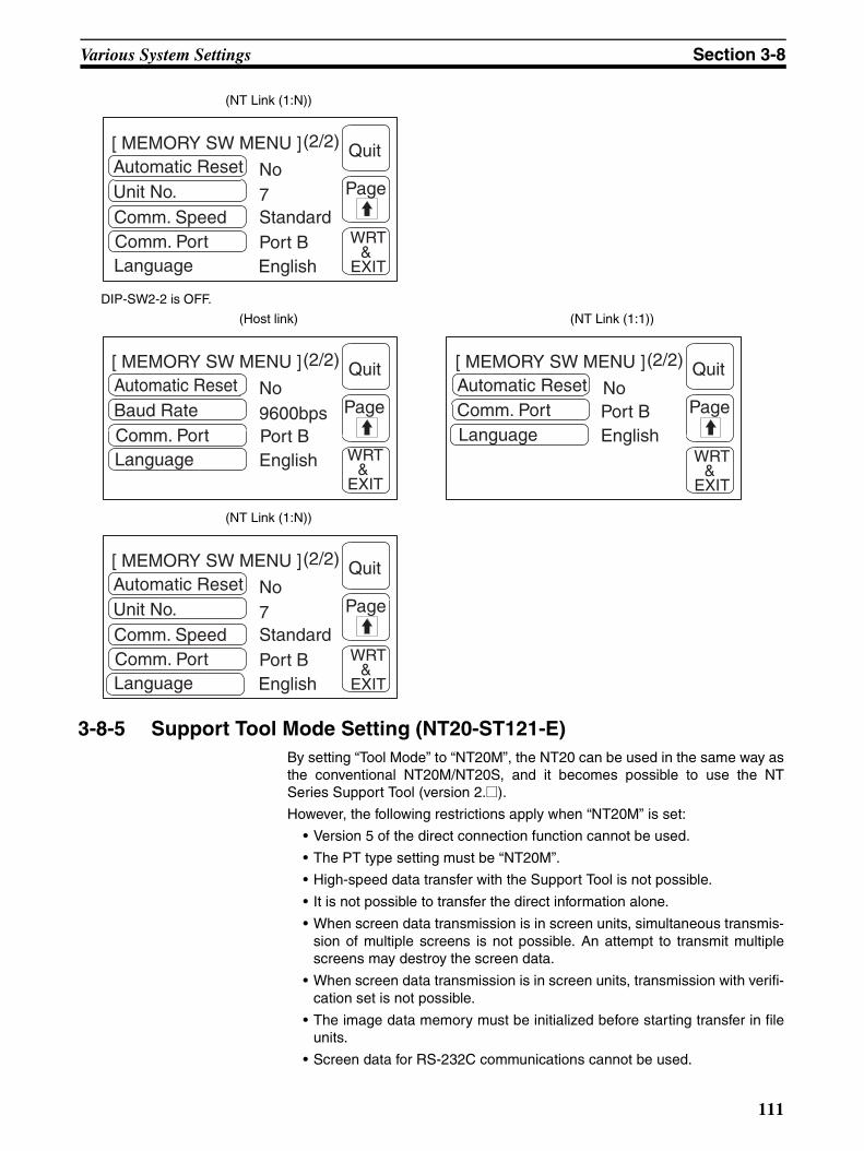
Various System Settings Section 3-8
3-8-5 Support Tool Mode Setting (NT20-ST121-E)By setting “Tool Mode” to “NT20M”, the NT20 can be used in the same way asthe conventional NT20M/NT20S, and it becomes possible to use the NTSeries Support Tool (version 2.@).
However, the following restrictions apply when “NT20M” is set:
• Version 5 of the direct connection function cannot be used.
• The PT type setting must be “NT20M”.
• High-speed data transfer with the Support Tool is not possible.
• It is not possible to transfer the direct information alone.
• When screen data transmission is in screen units, simultaneous transmis-sion of multiple screens is not possible. An attempt to transmit multiplescreens may destroy the screen data.
• When screen data transmission is in screen units, transmission with verifi-cation set is not possible.
• The image data memory must be initialized before starting transfer in fileunits.
• Screen data for RS-232C communications cannot be used.
(NT Link (1:N))
DIP-SW2-2 is OFF.
(Host link) (NT Link (1:1))
(NT Link (1:N))
Automatic ResetUnit No.
No7
(2/2) Quit[ MEMORY SW MENU ]
Page
WRT &
EXIT
Comm. SpeedComm. Port
StandardPort B
Language English
Automatic ResetBaud Rate
No9600bps
(2/2) Quit[ MEMORY SW MENU ]
Page
WRT &
EXIT
Comm. Port Port BLanguage English
Automatic Reset No
(2/2) Quit[ MEMORY SW MENU ]
Page
WRT &
EXIT
Comm. Port Port BLanguage English
Automatic ResetUnit No.
No7
(2/2) Quit[ MEMORY SW MENU ]
Page
WRT &
EXIT
Comm. SpeedComm. Port
StandardPort B
Language English
111

Various System Settings Section 3-8
Set the Support Tool mode by the menu operation from the system menushown below.
To quit after setting the selected item, press the WRT & EXIT touch switch. Toquit without setting, press the Quit touch switch. The NT20 will enter the RUNmode.
• When “NT20M” or “NT20S” is set, the NT20M/NT20S compatible mode isestablished and the terminal can be used as an NT20M/NT20S.
• When “NT20” is set, the terminal can be used as an NT20.
Note Before uploading screen data from the NT20 to the Support Tool,confirm that the model information for the screen data in the NT20and the Tool's transfer mode match. If they do not match, the up-load may fail or data may change, preventing correct operation.
3-8-6 Lamp Bit Control (NT20-ST128)When using the NT20-ST128 (using the RS-232C interface for communica-tions with the host), you can select whether lamp status is controlled by bitdesignation or not.
The factory setting for this function is “Enable” (lamps numbered 0 to 31 con-trolled by bits).
[ SYSTEM MENU ]
QuitTransmit ModeMaintenance Mode
Select “Maintenance Mode”.
[ MAINTENANCE MENU ]QuitPT SettingI/O Check
DIP-SW Status
Init. MemoryMemory Switch
Select “Memory Switch”.
Comm. TypeKey SoundBuzzer Sound
Host LinkOFF
Bk light OffTool Mode
OFFNoneNT20S
(1/2) Quit[ MEMORY SW MENU ]
Page
WRT &
EXIT
Each time the “Tool Mode” touch switch is pressed, the setting option alternates between “NT20”, “NT20S”, and “NT20M”.(The figure to the left shows the NT20-ST121@-E screen.)
112

Various System Settings Section 3-8
Set the lamp bit control function by the menu operation from the System Menu as described below.
[ SYSTEM MENU ]
QuitTransmit ModeMaintenance Mode
Select “Maintenance Mode”.
[ MAINTENANCE MENU ]QuitPT SettingI/O Check
DIP-SW Status
Init. MemoryMemory Switch
Select “Memory Switch”.
Key SoundBuzzer SoundBk light Off
ONON
Tool ModeAutomatic Reset
10 minNT20SYes
(1/3) Quit[MEMORY SW MENU]
Page
WRT &
EXIT
Select “Page down”.
Data BitsStop BitsParity Check
8 bits1 bit
Flow ControlBaud Rate
EvenRS/CS19200 ps
(2/3) Quit[MEMORY SW MENU]
Page
WRT &
EXIT
Select “Page down”.
113
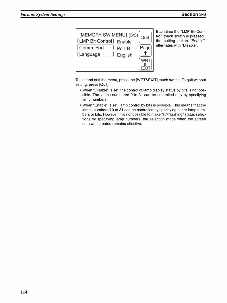
Various System Settings Section 3-8
To set and quit the menu, press the [WRT&EXIT] touch switch. To quit withoutsetting, press [Quit].
• When “Disable” is set, the control of lamp display status by bits is not pos-sible. The lamps numbered 0 to 31 can be controlled only by specifyinglamp numbers.
• When “Enable” is set, lamp control by bits is possible. This means that thelamps numbered 0 to 31 can be controlled by specifying either lamp num-bers or bits. However, it is not possible to make “lit”/”flashing” status selec-tions by specifying lamp numbers: the selection made when the screendata was created remains effective.
LMP Bit ControlComm. PortLanguage
EnablePort BEnglish
(3/3) Quit[MEMORY SW MENU]
Page
WRT &
EXIT
Each time the “LMP Bit Con-trol” touch switch is pressed,the setting option “Enable”alternates with “Disable”.
114
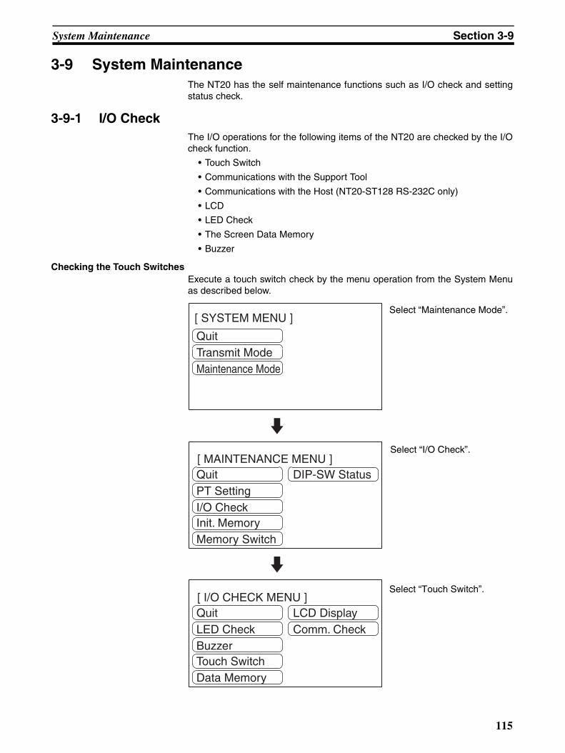
System Maintenance Section 3-9
3-9 System MaintenanceThe NT20 has the self maintenance functions such as I/O check and settingstatus check.
3-9-1 I/O CheckThe I/O operations for the following items of the NT20 are checked by the I/Ocheck function.
• Touch Switch
• Communications with the Support Tool
• Communications with the Host (NT20-ST128 RS-232C only)
• LCD
• LED Check
• The Screen Data Memory
• Buzzer
Checking the Touch SwitchesExecute a touch switch check by the menu operation from the System Menuas described below.
[ SYSTEM MENU ]
QuitTransmit ModeMaintenance Mode
Select “Maintenance Mode”.
[ MAINTENANCE MENU ]QuitPT SettingI/O Check
DIP-SW Status
Init. MemoryMemory Switch
Select “I/O Check”.
[ I/O CHECK MENU ]QuitLED CheckBuzzer
LCD DisplayComm. Check
Touch SwitchData Memory
Select “Touch Switch”.
115
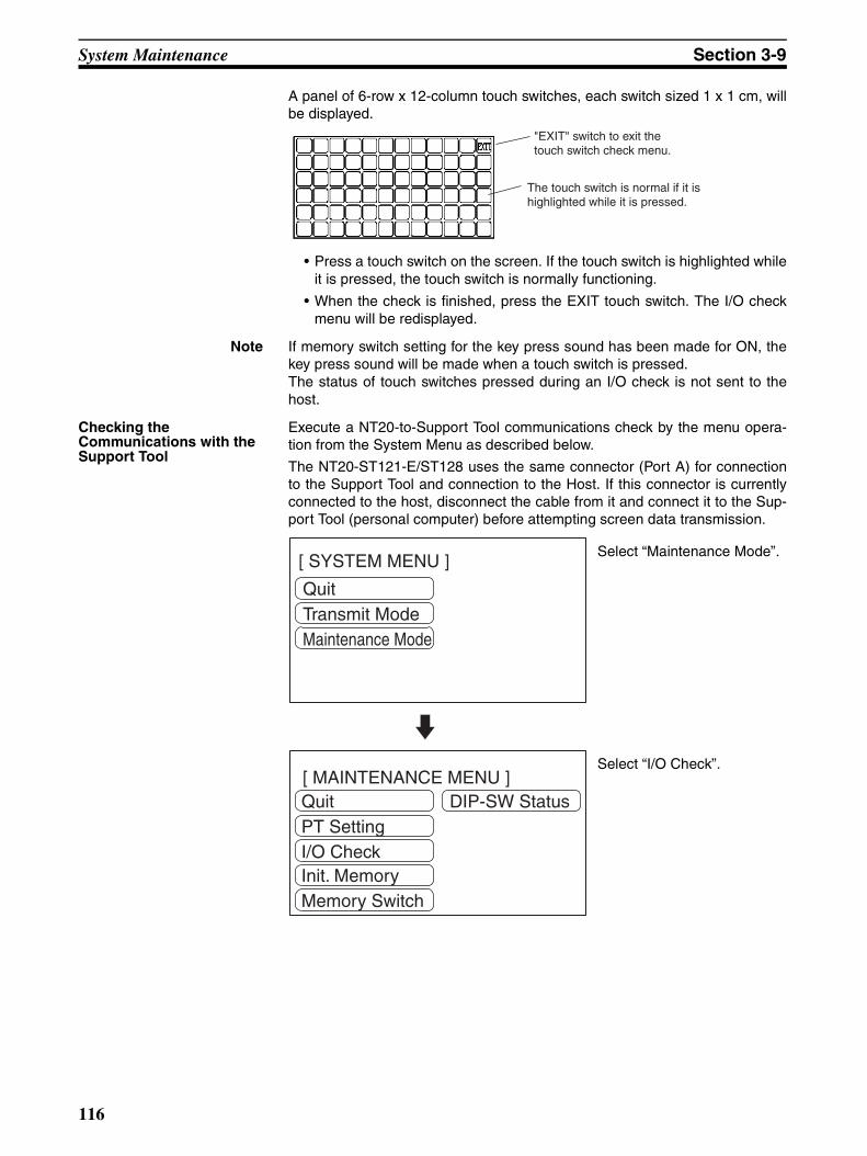
System Maintenance Section 3-9
A panel of 6-row x 12-column touch switches, each switch sized 1 x 1 cm, willbe displayed.
• Press a touch switch on the screen. If the touch switch is highlighted whileit is pressed, the touch switch is normally functioning.
• When the check is finished, press the EXIT touch switch. The I/O checkmenu will be redisplayed.
Note If memory switch setting for the key press sound has been made for ON, thekey press sound will be made when a touch switch is pressed.The status of touch switches pressed during an I/O check is not sent to thehost.
Checking the Communications with the Support Tool
Execute a NT20-to-Support Tool communications check by the menu opera-tion from the System Menu as described below.
The NT20-ST121-E/ST128 uses the same connector (Port A) for connectionto the Support Tool and connection to the Host. If this connector is currentlyconnected to the host, disconnect the cable from it and connect it to the Sup-port Tool (personal computer) before attempting screen data transmission.
"EXIT" switch to exit the touch switch check menu.
The touch switch is normal if it is highlighted while it is pressed.
[ SYSTEM MENU ]
QuitTransmit ModeMaintenance Mode
Select “Maintenance Mode”.
[ MAINTENANCE MENU ]QuitPT SettingI/O Check
DIP-SW Status
Init. MemoryMemory Switch
Select “I/O Check”.
116
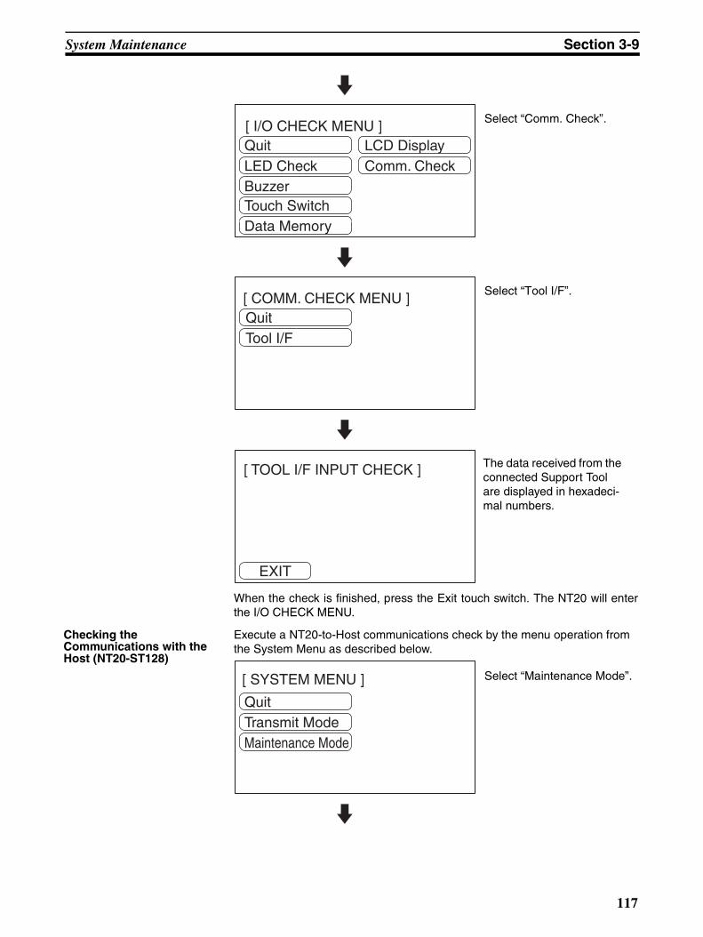
System Maintenance Section 3-9
When the check is finished, press the Exit touch switch. The NT20 will enterthe I/O CHECK MENU.
Checking the Communications with the Host (NT20-ST128)
Execute a NT20-to-Host communications check by the menu operation from the System Menu as described below.
[ I/O CHECK MENU ]QuitLED CheckBuzzer
LCD DisplayComm. Check
Touch SwitchData Memory
Select “Comm. Check”.
[ COMM. CHECK MENU ]QuitTool I/F
Select “Tool I/F”.
EXIT
[ TOOL I/F INPUT CHECK ] The data received from the connected Support Tool are displayed in hexadeci-mal numbers.
[ SYSTEM MENU ]
QuitTransmit ModeMaintenance Mode
Select “Maintenance Mode”.
117
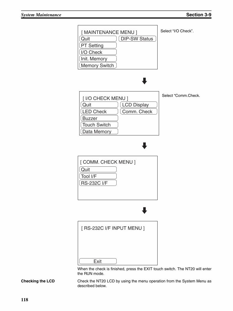
System Maintenance Section 3-9
When the check is finished, press the EXIT touch switch. The NT20 will enterthe RUN mode.
Checking the LCD Check the NT20 LCD by using the menu operation from the System Menu asdescribed below.
[ MAINTENANCE MENU ]QuitPT SettingI/O Check
DIP-SW Status
Init. MemoryMemory Switch
Select “I/O Check”.
[ I/O CHECK MENU ]QuitLED CheckBuzzer
LCD DisplayComm. Check
Touch SwitchData Memory
Select “Comm.Check.
[ COMM. CHECK MENU ]
QuitTool I/FRS-232C I/F
[ RS-232C I/F INPUT MENU ]
Exit
118
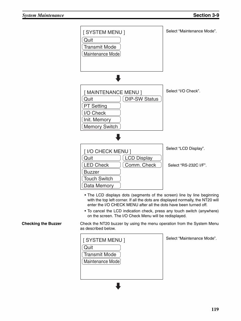
System Maintenance Section 3-9
• The LCD displays dots (segments of the screen) line by line beginningwith the top left corner. If all the dots are displayed normally, the NT20 willenter the I/O CHECK MENU after all the dots have been turned off.
• To cancel the LCD indication check, press any touch switch (anywhere)on the screen. The I/O Check Menu will be redisplayed.
Checking the Buzzer Check the NT20 buzzer by using the menu operation from the System Menuas described below.
[ SYSTEM MENU ]
QuitTransmit ModeMaintenance Mode
Select “Maintenance Mode”.
[ MAINTENANCE MENU ]QuitPT SettingI/O Check
DIP-SW Status
Init. MemoryMemory Switch
Select “I/O Check”.
[ I/O CHECK MENU ]QuitLED CheckBuzzer
LCD DisplayComm. Check
Touch SwitchData Memory
Select “LCD Display”.
[ SYSTEM MENU ]
QuitTransmit ModeMaintenance Mode
Select “Maintenance Mode”.
Select “RS-232C I/F”.
119
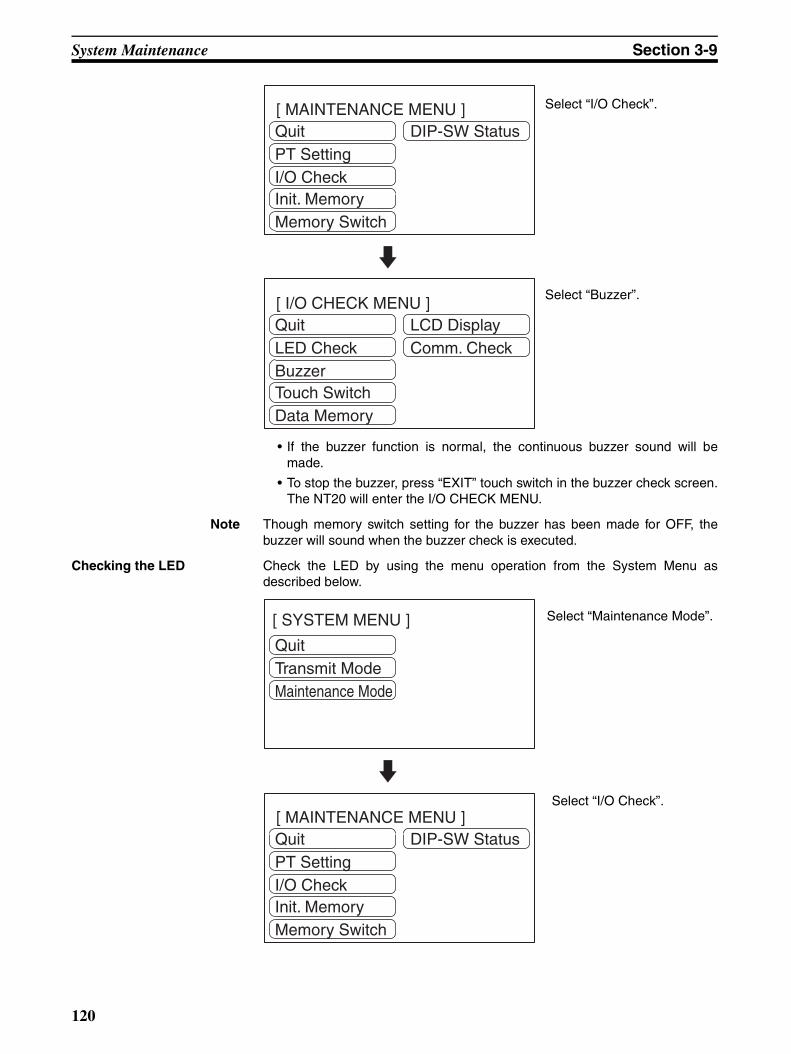
System Maintenance Section 3-9
• If the buzzer function is normal, the continuous buzzer sound will bemade.
• To stop the buzzer, press “EXIT” touch switch in the buzzer check screen.The NT20 will enter the I/O CHECK MENU.
Note Though memory switch setting for the buzzer has been made for OFF, thebuzzer will sound when the buzzer check is executed.
Checking the LED Check the LED by using the menu operation from the System Menu asdescribed below.
[ MAINTENANCE MENU ]QuitPT SettingI/O Check
DIP-SW Status
Init. MemoryMemory Switch
Select “I/O Check”.
[ I/O CHECK MENU ]QuitLED CheckBuzzer
LCD DisplayComm. Check
Touch SwitchData Memory
Select “Buzzer”.
[ SYSTEM MENU ]
QuitTransmit ModeMaintenance Mode
Select “Maintenance Mode”.
[ MAINTENANCE MENU ]QuitPT SettingI/O Check
DIP-SW Status
Init. MemoryMemory Switch
Select “I/O Check”.
120

System Maintenance Section 3-9
The “RUN” LED on the front face of the NT20 will flash. Flashing cycle is about1 s (500 ms ON and 500 ms OFF).
• To quit the LED check, press the “EXIT” touch switch. The NT20 will enterthe I/O CHECK MENU.
Checking the Screen MemoryCheck the screen memory by using the menu operation from the SystemMenu as described below.
Note When the screen data memory is checked, the memory is initialized and allthe screen data is lost. Check that the screen data has been backed up usingthe Support Tool before executing a screen data memory check.
[ I/O CHECK MENU ]QuitLED CheckBuzzer
LCD DisplayComm. Check
Touch SwitchData Memory
Select “LED Check”.
[ SYSTEM MENU ]
QuitTransmit ModeMaintenance Mode
Select “Maintenance Mode”.
[ MAINTENANCE MENU ]QuitPT SettingI/O Check
DIP-SW Status
Init. MemoryMemory Switch
Select “I/O Check”.
121

System Maintenance Section 3-9
The screen memory check will start.
While the screen memory is checked, the “Memory checking...” message willbe displayed.
• If the memory check has been normally completed, the “Memory is OK”message will be displayed.
• To quit the memory check, press the “Cancel” touch switch. The NT20 willenter the I/O CHECK MENU.
• If the “Memory error!” message is displayed, the screen data memorymay have been used up to its service life or there may be a hardwarefault. In that case, initialize the screen data memory and check the mem-ory again. If the same error message is displayed again, consult theOMRON Service Center.
3-9-2 Checking the PT SettingDisplay the NT20 settings by using the menu operation from the System Menuas described below.
[ I/O CHECK MENU ]QuitLED CheckBuzzer
LCD DisplayComm. Check
Touch SwitchData Memory
Select “Data Memory”.
TESTSTART
[ SCREEN DATA MEMORY CHECK ] Caution!! This test will destroy the Screen Data.
CANCEL
Press “TEST START”.Pressing “Cancel” will cancel the memory check.
[ SYSTEM MENU ]
QuitTransmit ModeMaintenance Mode
Select “Maintenance Mode”.
122

System Maintenance Section 3-9
(Host link) (NT Link (1:1))
(NT Link (1:N))
(C200H) (RS-232C) (NT20-ST128)
• The current PT settings will be displayed.
• Pressing the “EXIT” touch switch will exit the PT settings display, and theNT20 will return to the RUN Mode.
[ MAINTENANCE MENU ]QuitPT SettingI/O Check
DIP-SW Status
Init. MemoryMemory Switch
Select “PT Setting”.
EXIT
[ PT SETTING ]
EXIT
[ PT SETTING ]
PT Control Area DM0000PT Notify Area DM0010Comm. Type Host LinkBaud Rate 9600bps
PT Control Area DM0000PT Notify Area DM0010Comm. Type NT Link
EXIT
[ PT SETTING ]
PT Control Area DM0000PT Notify Area DM0010Comm. Type NT Link 1:NUnit No. 7
[ PT SETTING ]
EXIT
[ PT SETTING ]
PT Control Area DM0000PT Notify Area DM0010Comm. Type C200HUnit No. 0
Data Bits 8 bitsStop Bits 1 bitParity Check EvenFlow Control RS/CSBaud Rate 19200 bps
EXIT
123
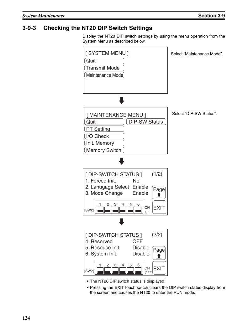
System Maintenance Section 3-9
3-9-3 Checking the NT20 DIP Switch SettingsDisplay the NT20 DIP switch settings by using the menu operation from theSystem Menu as described below.
• The NT20 DIP switch status is displayed.
• Pressing the EXIT touch switch clears the DIP switch status display fromthe screen and causes the NT20 to enter the RUN mode.
[ SYSTEM MENU ]
QuitTransmit ModeMaintenance Mode
Select “Maintenance Mode”.
[ MAINTENANCE MENU ]QuitPT SettingI/O Check
DIP-SW Status
Init. MemoryMemory Switch
Select “DIP-SW Status”.
[ DIP-SWITCH STATUS ]
ONOFF[SW2]
1. Forced Init. No2. Lanugage Select Enable3. Mode Change Enable
64321 5EXIT
Page
(1/2)
[ DIP-SWITCH STATUS ]
ONOFF[SW2]
4. Reserved OFF5. Resouce Init. Disable6. System Init. Disable
64321 5EXIT
Page
(2/2)
124

System Maintenance Section 3-9
Note If the DIP switch settings have been changed when the NT20 is powered,reset the power to the NT20. The changes with the DIP switches becomeeffective only after the power supply is reset.
125
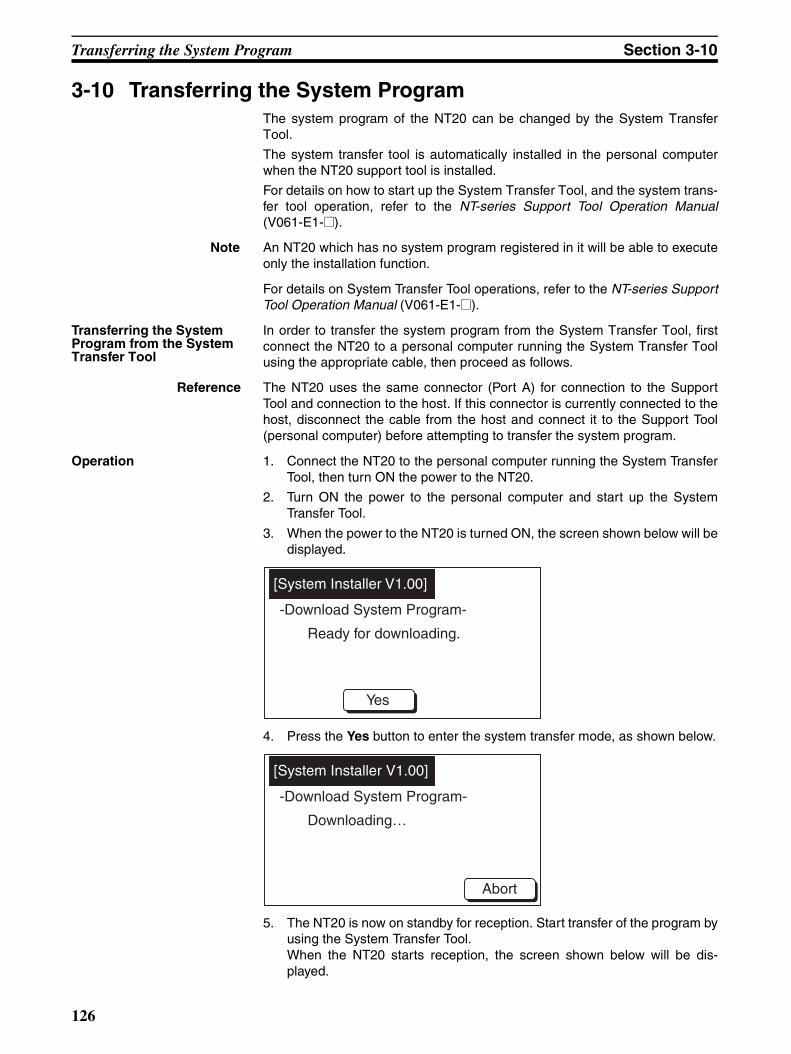
Transferring the System Program Section 3-10
3-10 Transferring the System ProgramThe system program of the NT20 can be changed by the System TransferTool.
The system transfer tool is automatically installed in the personal computerwhen the NT20 support tool is installed.
For details on how to start up the System Transfer Tool, and the system trans-fer tool operation, refer to the NT-series Support Tool Operation Manual(V061-E1-@).
Note An NT20 which has no system program registered in it will be able to executeonly the installation function.
For details on System Transfer Tool operations, refer to the NT-series SupportTool Operation Manual (V061-E1-@).
Transferring the System Program from the System Transfer Tool
In order to transfer the system program from the System Transfer Tool, firstconnect the NT20 to a personal computer running the System Transfer Toolusing the appropriate cable, then proceed as follows.
Reference The NT20 uses the same connector (Port A) for connection to the SupportTool and connection to the host. If this connector is currently connected to thehost, disconnect the cable from the host and connect it to the Support Tool(personal computer) before attempting to transfer the system program.
Operation 1. Connect the NT20 to the personal computer running the System TransferTool, then turn ON the power to the NT20.
2. Turn ON the power to the personal computer and start up the SystemTransfer Tool.
3. When the power to the NT20 is turned ON, the screen shown below will bedisplayed.
4. Press the Yes button to enter the system transfer mode, as shown below.
5. The NT20 is now on standby for reception. Start transfer of the program byusing the System Transfer Tool.When the NT20 starts reception, the screen shown below will be dis-played.
Yes
-Download System Program-
Ready for downloading.
[System Installer V1.00]
Abort
-Download System Program-
[System Installer V1.00]
Downloading…
126

Transferring the System Program Section 3-10
6. When transfer of the system program has been completed, the NT20 willdisplay the screen shown below.
7. Press the Run system Button when using the system transfer tool to re-turn to run mode.
Points to Observe during Transfer of the System Program
If any of the following events or a system error occurs during transfer of thesystem program, the program will not be installed in the NT20 correctly.
• The power to the NT20 is turned OFF, or the NT20 is reset during transfer.
• The power to the personal computer that is running the System TransferTool is turned OFF, or the personal computer is reset, during transfer.
• The cable connecting the personal computer running the System TransferTool and the NT20 becomes disconnected or sustains a wire breakageduring transfer.
• Transfer is terminated by pressing the Abort Button on the NT20.
• Transfer is terminated by pressing the ESC key of the personal computerrunning the System Transfer Tool.
In the event of any of the above, there is a possibility that the NT20 will notoperate or that unpredictable malfunctions will occur.
To prevent this, turn ON DIP switch SW2-6 to erase the system program afterthe problem has occurred. For details on erasing the system program with theDIP switch, refer to Method for Erasing the System Program (page 127).
Method for Erasing the System Program
In order to erase the system program, the system program area must becleared.If a system program already exists, it must be erased before the new one canbe transferred.
Use the following procedure to erase the system program.
Operation 1. Set DIP SW2-6 to the ON position and turn ON the power or reset. The fol-lowing screen will be displayed.
Abort
-Download System Program-
[System Installer V1.00]
Downloading…
Run System
-Download System Program-
Downloading is completed
[System Installer V1.00]
127
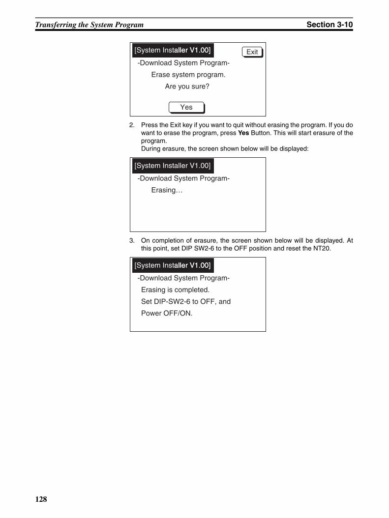
Transferring the System Program Section 3-10
2. Press the Exit key if you want to quit without erasing the program. If you dowant to erase the program, press Yes Button. This will start erasure of theprogram.During erasure, the screen shown below will be displayed:
3. On completion of erasure, the screen shown below will be displayed. Atthis point, set DIP SW2-6 to the OFF position and reset the NT20.
Yes
-Download System Program-
Erase system program.
[System Installer V1.00]aller V1.00] Exit
Are you sure?
-Download System Program-
[System Installer V1.00]
Erasing…
-Download System Program-
Set DIP-SW2-6 to OFF, and
[System Installer V1.00]aller V1.00]
Erasing is completed.
Power OFF/ON.
128
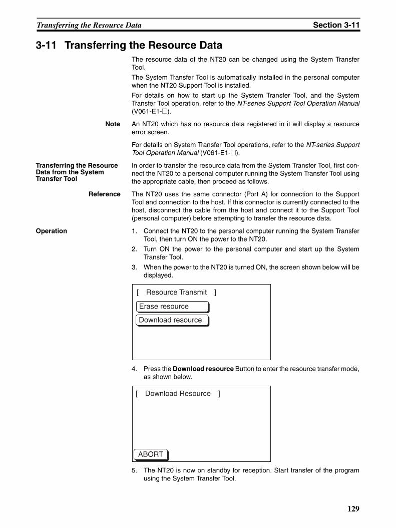
Transferring the Resource Data Section 3-11
3-11 Transferring the Resource DataThe resource data of the NT20 can be changed using the System TransferTool.
The System Transfer Tool is automatically installed in the personal computerwhen the NT20 Support Tool is installed.
For details on how to start up the System Transfer Tool, and the SystemTransfer Tool operation, refer to the NT-series Support Tool Operation Manual(V061-E1-@).
Note An NT20 which has no resource data registered in it will display a resourceerror screen.
For details on System Transfer Tool operations, refer to the NT-series SupportTool Operation Manual (V061-E1-@).
Transferring the Resource Data from the System Transfer Tool
In order to transfer the resource data from the System Transfer Tool, first con-nect the NT20 to a personal computer running the System Transfer Tool usingthe appropriate cable, then proceed as follows.
Reference The NT20 uses the same connector (Port A) for connection to the SupportTool and connection to the host. If this connector is currently connected to thehost, disconnect the cable from the host and connect it to the Support Tool(personal computer) before attempting to transfer the resource data.
Operation 1. Connect the NT20 to the personal computer running the System TransferTool, then turn ON the power to the NT20.
2. Turn ON the power to the personal computer and start up the SystemTransfer Tool.
3. When the power to the NT20 is turned ON, the screen shown below will bedisplayed.
4. Press the Download resource Button to enter the resource transfer mode,as shown below.
5. The NT20 is now on standby for reception. Start transfer of the programusing the System Transfer Tool.
Erase resource
Download resource
[ Resource Transmit ]
ABORT
[ Download Resource ]
129
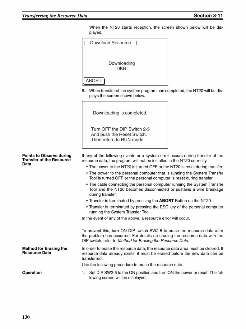
Transferring the Resource Data Section 3-11
When the NT20 starts reception, the screen shown below will be dis-played.
6. When transfer of the system program has completed, the NT20 will be dis-plays the screen shown below.
Points to Observe during Transfer of the Resource Data
If any of the following events or a system error occurs during transfer of theresource data, the program will not be installed in the NT20 correctly.
• The power to the NT20 is turned OFF or the NT20 is reset during transfer.
• The power to the personal computer that is running the System TransferTool is turned OFF or the personal computer is reset during transfer.
• The cable connecting the personal computer running the System TransferTool and the NT20 becomes disconnected or sustains a wire breakageduring transfer.
• Transfer is terminated by pressing the ABORT Button on the NT20.
• Transfer is terminated by pressing the ESC key of the personal computerrunning the System Transfer Tool.
In the event of any of the above, a resource error will occur.
To prevent this, turn ON DIP switch SW2-5 to erase the resource data afterthe problem has occurred. For details on erasing the resource data with theDIP switch, refer to Method for Erasing the Resource Data.
Method for Erasing the Resource Data
In order to erase the resource data, the resource data area must be cleared. Ifresource data already exists, it must be erased before the new data can betransferred.
Use the following procedure to erase the resource data.
Operation 1. Set DIP SW2-5 to the ON position and turn ON the power or reset. The fol-lowing screen will be displayed.
ABORT
Downloading 0KB
[ Download Resource ]
Downloading is completed.
Turn OFF the DIP Switch 2-5 And push the Reset Switch.Then return to RUN mode.
130

Transferring the Resource Data Section 3-11
2. If you do want to erase the resource data, press the Erase resource But-ton. The following screen will be displayed.
3. Press the No Button if you want to quit without erasing the resource data.If you do want to erase the resource data, press the Yes Button. This willstart erasure of the resource data.
During erasure, the screen shown below is displayed:
4. On completion of erasure, the screen shown below will be displayed.
Erase resource
Download resource
[ Resource Transmit ]
Erase resource?
Yes
No
Erase resource?
Yes
No
Erasing
Erase resource
Download resource
[ Resource Transmit ]
131

Transferring the Resource Data Section 3-11
132
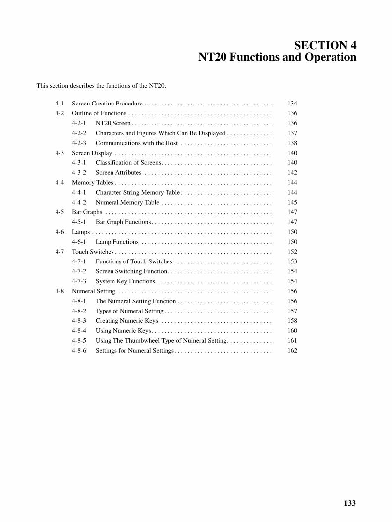
SECTION 4NT20 Functions and Operation
This section describes the functions of the NT20.
4-1 Screen Creation Procedure . . . . . . . . . . . . . . . . . . . . . . . . . . . . . . . . . . . . . . . 134
4-2 Outline of Functions . . . . . . . . . . . . . . . . . . . . . . . . . . . . . . . . . . . . . . . . . . . . 136
4-2-1 NT20 Screen . . . . . . . . . . . . . . . . . . . . . . . . . . . . . . . . . . . . . . . . . . . 136
4-2-2 Characters and Figures Which Can Be Displayed . . . . . . . . . . . . . . 137
4-2-3 Communications with the Host . . . . . . . . . . . . . . . . . . . . . . . . . . . . 138
4-3 Screen Display . . . . . . . . . . . . . . . . . . . . . . . . . . . . . . . . . . . . . . . . . . . . . . . . 140
4-3-1 Classification of Screens. . . . . . . . . . . . . . . . . . . . . . . . . . . . . . . . . . 140
4-3-2 Screen Attributes . . . . . . . . . . . . . . . . . . . . . . . . . . . . . . . . . . . . . . . 142
4-4 Memory Tables . . . . . . . . . . . . . . . . . . . . . . . . . . . . . . . . . . . . . . . . . . . . . . . . 144
4-4-1 Character-String Memory Table . . . . . . . . . . . . . . . . . . . . . . . . . . . . 144
4-4-2 Numeral Memory Table . . . . . . . . . . . . . . . . . . . . . . . . . . . . . . . . . . 145
4-5 Bar Graphs . . . . . . . . . . . . . . . . . . . . . . . . . . . . . . . . . . . . . . . . . . . . . . . . . . . 147
4-5-1 Bar Graph Functions. . . . . . . . . . . . . . . . . . . . . . . . . . . . . . . . . . . . . 147
4-6 Lamps . . . . . . . . . . . . . . . . . . . . . . . . . . . . . . . . . . . . . . . . . . . . . . . . . . . . . . . 150
4-6-1 Lamp Functions . . . . . . . . . . . . . . . . . . . . . . . . . . . . . . . . . . . . . . . . 150
4-7 Touch Switches . . . . . . . . . . . . . . . . . . . . . . . . . . . . . . . . . . . . . . . . . . . . . . . . 152
4-7-1 Functions of Touch Switches . . . . . . . . . . . . . . . . . . . . . . . . . . . . . . 153
4-7-2 Screen Switching Function . . . . . . . . . . . . . . . . . . . . . . . . . . . . . . . . 154
4-7-3 System Key Functions . . . . . . . . . . . . . . . . . . . . . . . . . . . . . . . . . . . 154
4-8 Numeral Setting . . . . . . . . . . . . . . . . . . . . . . . . . . . . . . . . . . . . . . . . . . . . . . . 156
4-8-1 The Numeral Setting Function . . . . . . . . . . . . . . . . . . . . . . . . . . . . . 156
4-8-2 Types of Numeral Setting . . . . . . . . . . . . . . . . . . . . . . . . . . . . . . . . . 157
4-8-3 Creating Numeric Keys . . . . . . . . . . . . . . . . . . . . . . . . . . . . . . . . . . 158
4-8-4 Using Numeric Keys. . . . . . . . . . . . . . . . . . . . . . . . . . . . . . . . . . . . . 160
4-8-5 Using The Thumbwheel Type of Numeral Setting. . . . . . . . . . . . . . 161
4-8-6 Settings for Numeral Settings. . . . . . . . . . . . . . . . . . . . . . . . . . . . . . 162
133

Screen Creation Procedure Section 4-1
4-1 Screen Creation ProcedureFollow the procedure shown below to create screens for the NT20.
The following gives the procedure assuming that the setting for the PT hasbeen completed. The operating procedure for the Support Tool is not givenhere. For the operating procedure for the Support Tool, refer to the NT-seriesSupport Tool Version 4.8 for Windows Operation Manual (Cat. No. V061-E1-@).
Designate a work file.
Creating a New Screen
Tool Setting (PT model)
Set the PT model as follows:
NT20S: Set NT20S.
System Setting (Memory Switch Setting)
Setting for PT Status Control/Notify Area
Correcting an Existing File
File Designation
Importing DOS Version Data
File Designation
Designate the work file to be data converted.
NT20: Set NT20.
Set the memory switches that determine the basic operation of the PT. The numeral/character string/bit memory table entry settings should also be made at this stage.
Allocate words for the PT status control area and PT status notify area, necessary for the direct connection function, in the host.For details, refer to 5-1-3 NT20 Status Control and Notification to PLC.
134
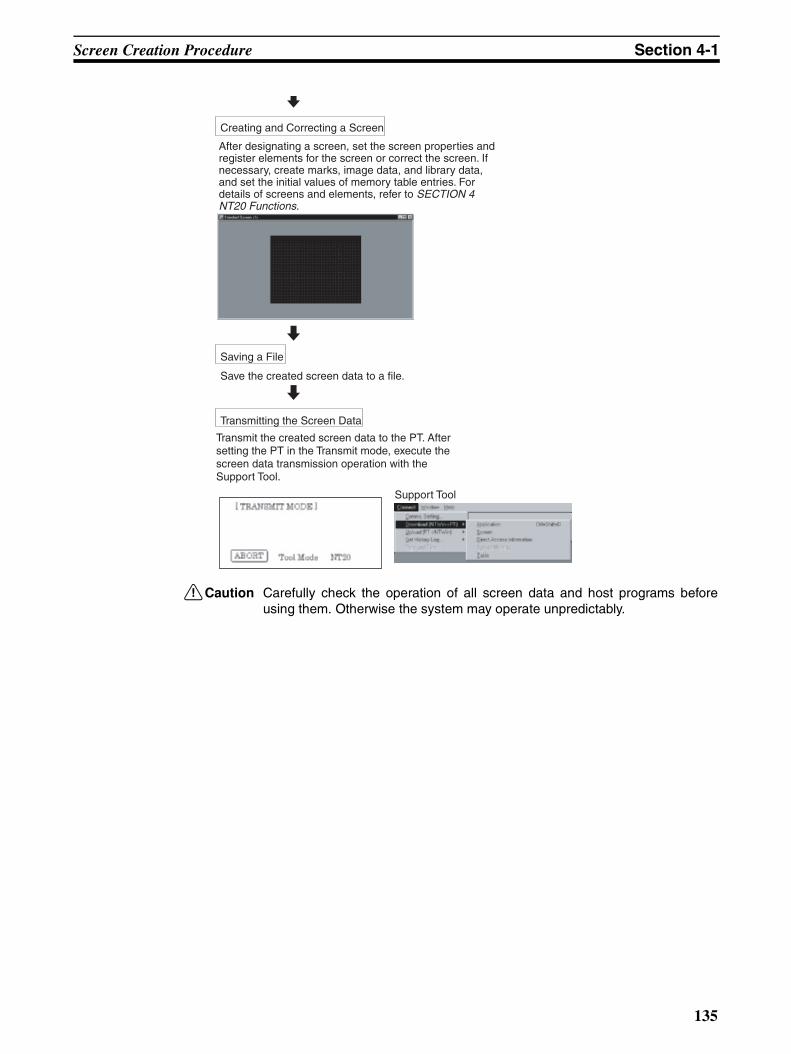
Screen Creation Procedure Section 4-1
!Caution Carefully check the operation of all screen data and host programs beforeusing them. Otherwise the system may operate unpredictably.
Creating and Correcting a Screen
Saving a File
Save the created screen data to a file.
Transmitting the Screen Data
Support Tool
After designating a screen, set the screen properties and register elements for the screen or correct the screen. If necessary, create marks, image data, and library data, and set the initial values of memory table entries. For details of screens and elements, refer to SECTION 4 NT20 Functions.
Transmit the created screen data to the PT. After setting the PT in the Transmit mode, execute the screen data transmission operation with the Support Tool.
135

Outline of Functions Section 4-2
4-2 Outline of Functions
4-2-1 NT20 ScreenThis section gives the outline of the screen which is the basis of all NT20 func-tions.
For specific operation procedure such as screen switching, refer to 5-1-4Switching the Screen Display (page 172).
Composition of the ScreenThe NT20 screen is composed of horizontal 256 dots x vertical 128 dots.Each dot is set by the combination of the X (horizontal) and Y (vertical) coordi-nates. The origin of coordinates (0, 0) is set at the top left corner of thescreen.
Screen Management The screens displayed on the NT20 are managed by the screen numbers.
When using the NT20, up to 495 screens can be created and screen numbersin the ranges 1 to 250 and 256 to 500 can be used (numbers 251 to 255 arereserved for system use).
The display screens can be switched or the start-up screen can be set by des-ignating the screen number from the Host.
Special Screen Number Screen number “0” is reserved for the system as the no-display screen. Selectthis to display nothing on the NT20 screen.
X coordinate (horizontal)
Y coordinate (vertical)
Coordinates (x, y)
255
255, 127127
00
136
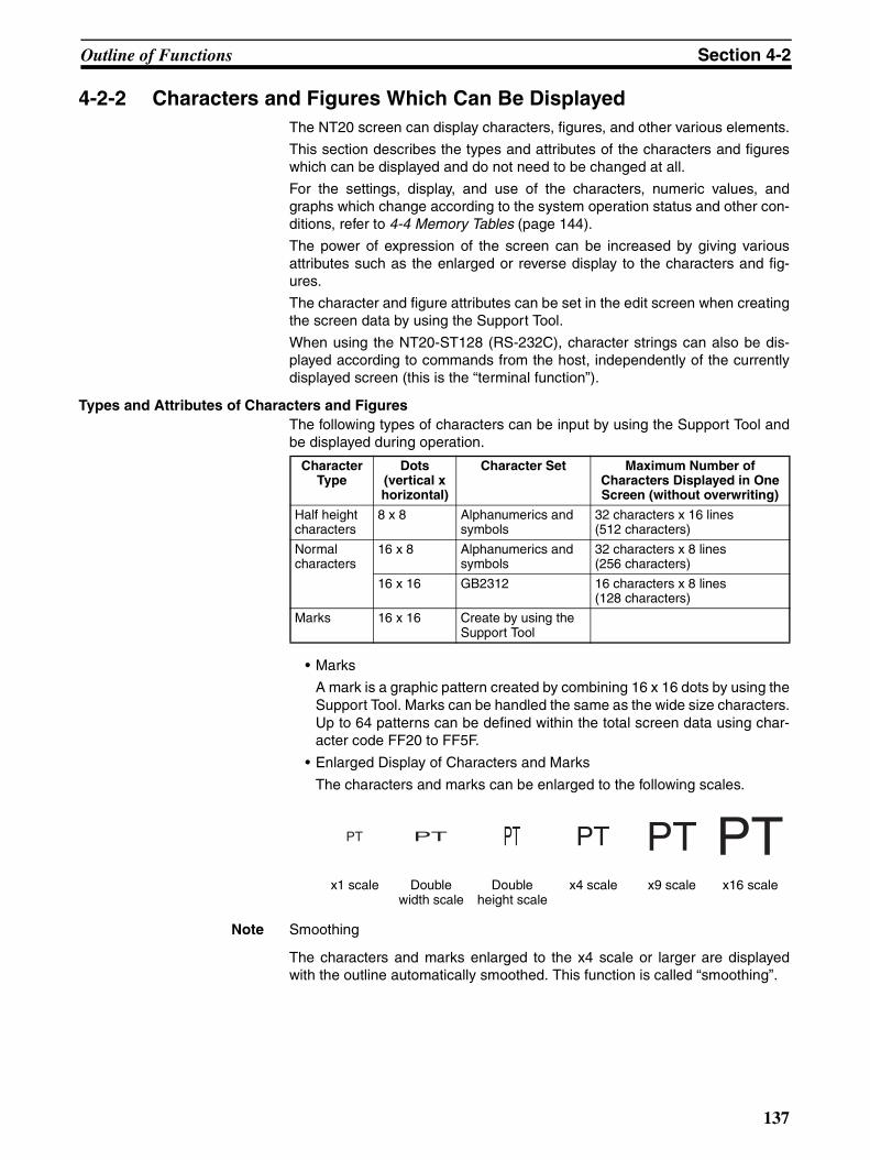
Outline of Functions Section 4-2
4-2-2 Characters and Figures Which Can Be DisplayedThe NT20 screen can display characters, figures, and other various elements.
This section describes the types and attributes of the characters and figureswhich can be displayed and do not need to be changed at all.
For the settings, display, and use of the characters, numeric values, andgraphs which change according to the system operation status and other con-ditions, refer to 4-4 Memory Tables (page 144).
The power of expression of the screen can be increased by giving variousattributes such as the enlarged or reverse display to the characters and fig-ures.
The character and figure attributes can be set in the edit screen when creatingthe screen data by using the Support Tool.
When using the NT20-ST128 (RS-232C), character strings can also be dis-played according to commands from the host, independently of the currentlydisplayed screen (this is the “terminal function”).
Types and Attributes of Characters and FiguresThe following types of characters can be input by using the Support Tool andbe displayed during operation.
• Marks
A mark is a graphic pattern created by combining 16 x 16 dots by using theSupport Tool. Marks can be handled the same as the wide size characters.Up to 64 patterns can be defined within the total screen data using char-acter code FF20 to FF5F.
• Enlarged Display of Characters and Marks
The characters and marks can be enlarged to the following scales.
Note Smoothing
The characters and marks enlarged to the x4 scale or larger are displayedwith the outline automatically smoothed. This function is called “smoothing”.
CharacterType
Dots(vertical xhorizontal)
Character Set Maximum Number ofCharacters Displayed in One Screen (without overwriting)
Half height characters
8 x 8 Alphanumerics andsymbols
32 characters x 16 lines(512 characters)
Normal characters
16 x 8 Alphanumerics andsymbols
32 characters x 8 lines(256 characters)
16 x 16 GB2312 16 characters x 8 lines(128 characters)
Marks 16 x 16 Create by using the Support Tool
x1 scale Double width scale
Double height scale
x4 scale x9 scale x16 scale
PT PT PT PT PT PT
137
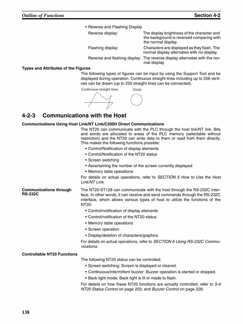
Outline of Functions Section 4-2
• Reverse and Flashing Display
Reverse display: The display brightness of the character and the background is reversed comparing withthe normal display.
Flashing display: Characters are displayed as they flash. The normal display alternates with no-display.
Reverse and flashing display: The reverse display alternates with the nor-mal display.
Types and Attributes of the FiguresThe following types of figures can be input by using the Support Tool and bedisplayed during operation. Continuous straight lines including up to 256 verti-ces can be drawn (up to 255 straight lines can be connected).
4-2-3 Communications with the HostCommunications Using Host Link/NT Link/C200H Direct Communications
The NT20 can communicate with the PLC through the host link/NT link. Bitsand words are allocated to areas of the PLC memory (selectable withoutrestriction) and the NT20 can write data to them or read from them directly.This makes the following functions possible:
• Control/Notification of display elements• Control/Notification of the NT20 status• Screen switching• Ascertaining the number of the screen currently displayed• Memory table operations
For details on actual operations, refer to SECTION 5 How to Use the HostLink/NT Link.
Communications through RS-232C
The NT20-ST128 can communicate with the host through the RS-232C inter-face. In other words, it can receive and send commands through the RS-232Cinterface, which allows various types of host to utilize the functions of theNT20:
• Control/notification of display elements
• Control/notification of the NT20 status
• Memory table operations
• Screen operation
• Display/deletion of characters/graphics
For details on actual operations, refer to SECTION 6 Using RS-232C Commu-nications.
Controllable NT20 FunctionsThe following NT20 status can be controlled:
• Screen switching: Screen is displayed or cleared.
• Continuous/intermittent buzzer: Buzzer operation is started or stopped.
• Back light mode: Back light is lit or made to flash.
For details on how these NT20 functions are actually controlled, refer to 5-4NT20 Status Control on page 203, and Buzzer Control on page 228.
Continuous straight lines Circle
138
Outline of Functions Section 4-2
Ascertainable Operating Status of the NT20The following operating status of the NT20 can be ascertained:
• NT20 operating/stopped status: Whether the NT20 is active or inactive
• Screen number: Number of the screen currently displayed
• Numeral setting input: Whether or not numerical values have been inputby numeral setting
For details on how these NT20 operating status is actually detected, refer to5-5 Notification of the Operating Status to the PLC (Determining the NT20Operating Status) on page 208, Screen Number Response on page 217, andEight-digit Number Input Notify on page 225.
!Caution To ensure system safety, be sure to periodically read the PT operating statusbit from the host in order to ensure that the PT is always operating normally.
139

Screen Display Section 4-3
4-3 Screen DisplayThis section describes the screen information required for the operation withthe NT20.
For details on how to change the displayed screen, refer to 5-1-4 Switchingthe Screen Display on page 172, and Display Specified Screen on page 216.For the methods used to ascertain the screen number of the screen currentlydisplayed, refer to 5-1-5 Notifying the PLC of the Display Screen (to Displaythe Number of Currently Displayed Screen) on page 174, and RequestScreen Number on page 216.
4-3-1 Classification of ScreensThe NT20 is provided with the following types of screens which are classifiedby the display method.
• Normal screen
• Overlapping screen
• Continuous screen
The screen type is set with each screen in the “Screen List” screen of theSupport Tool. Select a screen type according to the purpose, and create char-acters and figures on the screen.
Normal Screen A normal screen is the basic screen of the NT20. It is not necessary to selecta screen type (overlapping or consecutive) when to create the screen data ona normal screen.
When a normal screen is selected, existing screens will be erased and a nor-mal screen will be displayed.
Overlapping Screen Several normal screens can be overlapped and displayed as one screen. Agroup of overlapped screens is called an “overlapping screen”.
Several normal screens are displayed in the order of screen numbers whichhave been designated to each screen and form an overlapping screen. Up toeight screens can be overlapped to form one overlapping screen. The basescreen used for making an overlapping screen is called a “parent screen”, anda bunch of screens which are laid over the parent screen are called “childscreens”.
All display elements can be used on a parent screen.
The screen attributes such as a buzzer attribute set in the parent screenbecome effective in an overlapping screen.
Example Overlapping Screens
• Parent screen: #8
• Child screens: #10, #7, and #25
(1)
(2)
(3)
Screen #8
Screen #10
Screen #7
Screen #25
This is an overlapping screen.
This is an
overlapping
screen.
140
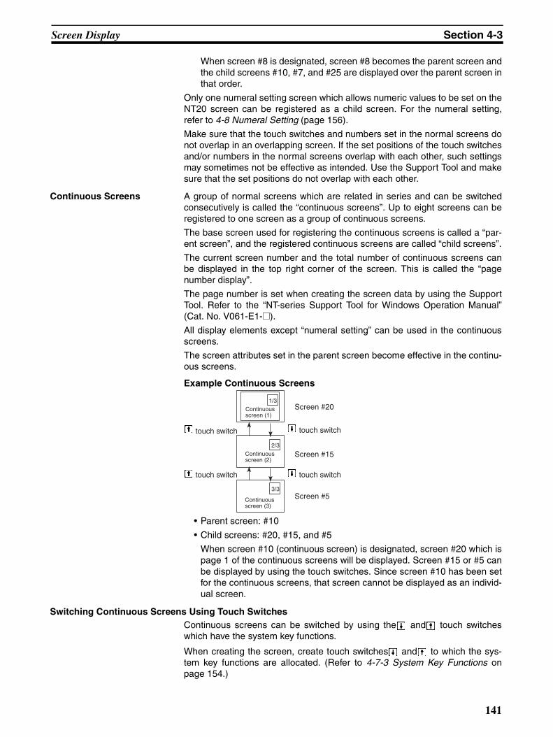
Screen Display Section 4-3
When screen #8 is designated, screen #8 becomes the parent screen andthe child screens #10, #7, and #25 are displayed over the parent screen inthat order.
Only one numeral setting screen which allows numeric values to be set on theNT20 screen can be registered as a child screen. For the numeral setting,refer to 4-8 Numeral Setting (page 156).
Make sure that the touch switches and numbers set in the normal screens donot overlap in an overlapping screen. If the set positions of the touch switchesand/or numbers in the normal screens overlap with each other, such settingsmay sometimes not be effective as intended. Use the Support Tool and makesure that the set positions do not overlap with each other.
Continuous Screens A group of normal screens which are related in series and can be switchedconsecutively is called the “continuous screens”. Up to eight screens can beregistered to one screen as a group of continuous screens.
The base screen used for registering the continuous screens is called a “par-ent screen”, and the registered continuous screens are called “child screens”.
The current screen number and the total number of continuous screens canbe displayed in the top right corner of the screen. This is called the “pagenumber display”.
The page number is set when creating the screen data by using the SupportTool. Refer to the “NT-series Support Tool for Windows Operation Manual”(Cat. No. V061-E1-@).
All display elements except “numeral setting” can be used in the continuousscreens.
The screen attributes set in the parent screen become effective in the continu-ous screens.
Example Continuous Screens
• Parent screen: #10
• Child screens: #20, #15, and #5
When screen #10 (continuous screen) is designated, screen #20 which ispage 1 of the continuous screens will be displayed. Screen #15 or #5 canbe displayed by using the touch switches. Since screen #10 has been setfor the continuous screens, that screen cannot be displayed as an individ-ual screen.
Switching Continuous Screens Using Touch SwitchesContinuous screens can be switched by using the and touch switcheswhich have the system key functions.
When creating the screen, create touch switches and to which the sys-tem key functions are allocated. (Refer to 4-7-3 System Key Functions onpage 154.)
1/3
2/3
3/3
Screen #20
Screen #15
Screen #5
touch switch
touch switch touch switch
touch switch
Continuous screen (1)
Continuous screen (2)
Continuous screen (3)
141

Screen Display Section 4-3
4-3-2 Screen AttributesEach screen can be set with a specific function by designating a screenattribute, so that the specific function can be executed by displaying thescreen. For example, by displaying a screen to which a “buzzer attribute” hasbeen set, the buzzer of the NT20 starts sounding.
Set the screen attributes for each screen on the “screen selection” screen ofthe Support Tool.Note that the Support Tool displays some items that are not used with theNT20.
The following several attributes can be set with one screen.
Buzzer Attribute This attribute will become effective to sound the buzzer in the NT20 when thescreen to which this attribute has been set is displayed. The buzzer sound canbe set as follows:
No: Buzzer does not sound when the screen is displayed.
Continuous sound: Buzzer sounds continuously.
Intermittent sound: Buzzer sounds intermittently at constant intervals.
The buzzer sound is set with the NT20 memory switch. The buzzer can alsobe set by using the Host. Refer to 3-8-2 Using the Buzzer on page 107 for thebuzzer setting using the memory switch.To stop the buzzer by using the screen operation, create a system key as atouch switch.
Numeral Setting Attribute Select whether the numeric keys are automatically displayed or the numerickeys are created at arbitrary positions on the numeral setting screen. The fol-lowing two numeral setting attributes are used.
System: The numeric keys registered to the system are automaticallydisplayed.
User: The numeric keys can be created at any arbitrary positions.
Note If the numeral setting attribute on the NT20 has been set for “system”, thetouch switches [ENT], and which are allocated to the system besides thenumeric keys need to be created. (Refer to 4-7-3 System Key Functions onpage 154.)
Bit Input Attributes (NT20-ST128 Only)
Select whether the host is notified of the touch switch number or bit informa-tion when the touch switch is pressed. There are two types of bit inputattribute in the screen attributes, as described below:
• Off: Bit control when a touch switch is pressed is invalid. Notifica-tion of the status of the touch switch is provided using its num-ber.
Production Status Line A: Normal Line B: Normal
1/3
142

Screen Display Section 4-3
• Touch SW:Bit control when a touch switch is pressed is valid. Notificationof the status of the touch switch is provided using bit informa-tion.
Backlight Attributes Select whether the backlight is lit or flashes when the screen is displayed.There are two types of backlight attribute in the screen attributes, as indicatedbelow:
• Lit: Backlight is lit when the screen is displayed.
• Flashing: Backlight flashes when the screen is displayed.
143
Memory Tables Section 4-4
4-4 Memory TablesThe NT20 has the “character-string memory table” for the character data andthe “numeral memory table” for numeric data which can be written andupdated by the PLC/Host.
The contents of the memory table entries can be set by using the SupportTool when displaying the memory table entries on the screen or by editing thetable.
4-4-1 Character-String Memory TableThe character-string memory table is an NT20 internal memory used to storethe character data. Up to 128 character-string memory table entries can beused, and up to 16 full size characters (32 bytes) can be stored in one mem-ory table entry. The character-string memory table entries at up to 32 posi-tions can be registered in one screen.
Displaying a Character StringThe character-string memory table entries are registered with table entrynumbers 0 to 127.
When creating the screen data by using the Support Tool, set the position onthe screen to display a character string and also set a character string numberto be displayed.
When the NT20 is operated, the screen displays the contents of the charac-ter-string memory table.
When using a direct connection, it is possible to display the contents of char-acter-string memory table entries by specifying their numbers with numeralmemory table entries (indirect specification), rather than directly changing thecharacter-string memory table contents.
For details on how to change currently displayed character strings, refer to 5-2-2 Changing Displayed Numerals or Character Strings (Changing the Con-tents of Allocated Words ... Direct Specification) on page 182, and WriteCharacter-string Memory Table on page 218.
When using the NT20-ST128 (RS-232C), character strings can be also dis-played according to commands from the host, independently of the currentlydisplayed screen (terminals Function). Refer to Specify Displayed Characterson page 232.
Characters and Figures Which Can Be Displayed The power of expression of the screen can be increased by giving variousattributes such as the enlarged or reverse display to the characters of thecharacter-string memory table.
The character attributes can be set in the edit screen when creating thescreen data by using the Support Tool.
The following types of characters can be displayed on the NT20:
CharacterType
Dots(vertical xhorizontal)
Character Set Maximum Number ofCharacters Displayed in OneScreen (without overwriting)
Half sizecharacters
8 x 8 Alphanumerics andsymbols
32 characters x 16 lines(512 characters)
144
Memory Tables Section 4-4
• Enlarged Display of Characters and Marks
The characters and marks can be enlarged to the following scales.
Double width scale, Double height scale, x4 scale, x9 scale, x16 scale
• Smoothing
The characters and marks enlarged to the x4 scale or larger are displayedwith the outline automatically smoothed. This function is called “smooth-ing”.
• Reverse and Flashing Display
Reverse display: The display brightness of the character andthe background is reversed comparing withthe normal display.
Flashing display: Characters are displayed as they flash. Thenormal display alternates with no-display.
Reverse and flashing display: The reverse display alternates with the nor-mal display.
4-4-2 Numeral Memory TableThe numeral memory table is an NT20 internal memory used to store thenumeral data. Up to 128 numeral memory table entries can be used, and upto eight digits (four bytes) of numeral data (including signs) can be stored inone numeral memory table entry. The numeral memory table entries at up to50 positions can be registered in one screen.
Displaying a Numeral The numeral memory table entries are registered with table entry numbers 0to 127.
When creating the screen data by using the Support Tool, set the position onthe screen to display a numeral and also set a numeral number to be dis-played.
When the NT20 is operated, the screen displays the contents of the numeralmemory table.
For details on how to change the currently displayed numeric data, refer to5-2-2 Changing Displayed Numerals or Character Strings (Changing theContents of Allocated Words ... Direct Specification) on page 182, andFour-digit Write Numeral Memory Table on page 219.
Numerals Which Can Be Displayed The power of expression of the screen can be increased by giving variousattributes such as the enlarged or reverse display to the numerals of thenumeral memory table.
The numeral attributes can be set in the edit screen when creating the screendata by using the Support Tool.
• Digits of the whole numbers: 1 to 8 digits
• Digits of the decimal fraction: 0 to 7 digits
• Character sizes: Half, normal
• Enlarged display: Double width, double height, x4, x9, x16
Normal sizecharacters
8 x 16 Alphanumerics andsymbols
32 characters x 8 lines(256 characters)
16 x 16 GB2312 16 characters x 8 lines(128 characters)
Marks 16 x 16 Create by using the Support Tool
145
Memory Tables Section 4-4
The characters enlarged to the x4 scale orlarger are displayed with the outline auto-matically smoothed. This function is called“smoothing”.
• Display attribute: Normal, reverse, flashing, reverse andflashing
• Sign display setting
• Decimal/hexadecimal display setting
• Zero suppress setting
To display one numeral memory table entry on several different screens simul-taneously, the display attributes on such screens must be the same. If thereare discrepancies among the display attributes, the numeral table entry maynot be displayed correctly.
Note Zero Suppress Setting
The numeral data are displayed in designated display areas as right-aligned.If the number of digits of a numeral data is smaller than that of the displayarea, number “0”s will be displayed at the vacant digits. These “0”s will not bedisplayed if the zero suppress setting is made for “Yes”.
146
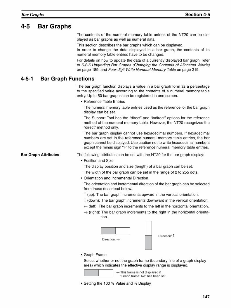
Bar Graphs Section 4-5
4-5 Bar GraphsThe contents of the numeral memory table entries of the NT20 can be dis-played as bar graphs as well as numeral data.
This section describes the bar graphs which can be displayed.In order to change the data displayed in a bar graph, the contents of itsnumeral memory table entries have to be changed.
For details on how to update the data of a currently displayed bar graph, referto 5-2-5 Upgrading Bar Graphs (Changing the Contents of Allocated Words)on page 189, and Four-digit Write Numeral Memory Table on page 219.
4-5-1 Bar Graph FunctionsThe bar graph function displays a value in a bar graph form as a percentageto the specified value according to the contents of a numeral memory tableentry. Up to 50 bar graphs can be registered in one screen.
• Reference Table Entries
The numeral memory table entries used as the reference for the bar graphdisplay can be set.
The Support Tool has the “direct” and “indirect” options for the referencemethod of the numeral memory table. However, the NT20 recognizes the“direct” method only.
The bar graph display cannot use hexadecimal numbers. If hexadecimalnumbers are set in the reference numeral memory table entries, the bargraph cannot be displayed. Use caution not to write hexadecimal numbersexcept the minus sign “F” to the reference numeral memory table entries.
Bar Graph Attributes The following attributes can be set with the NT20 for the bar graph display:
• Position and Size
The display position and size (length) of a bar graph can be set.
The width of the bar graph can be set in the range of 2 to 255 dots.
• Orientation and Incremental Direction
The orientation and incremental direction of the bar graph can be selectedfrom those described below.
↑ (up): The bar graph increments upward in the vertical orientation.
↓ (down): The bar graph increments downward in the vertical orientation.
← (left): The bar graph increments to the left in the horizontal orientation.
→ (right): The bar graph increments to the right in the horizontal orienta-tion.
• Graph Frame
Select whether or not the graph frame (boundary line of a graph display area) which indicates the effective display range is displayed.
• Setting the 100 % Value and % Display
Direction: →Direction: ↑
← This frame is not displayed if "Graph frame: No" has been set.
147

Bar Graphs Section 4-5
Set a value which corresponds to 100 % for the “100 % value”. The avail-able value range is “0 to 99999999” (eight digits max.). For the “% display”,whether or not the proportion (percentage) of the reference numeral mem-ory table value to the “100 % value” is displayed in a numeral can be se-lected. The display value is calculated as follows:
“% display” value = Numeral memory table value ÷ “100 % value” x 100
For the font and attributes used for the numeral display, refer to NumeralsWhich Can Be Displayed on page 145.
• Sign Display and Display Method
Select whether or not the bar graph which indicates a value below 0 % isdisplayed.
To Display Values Below 0 %: Sign Display “Yes”
The bar graph is displayed in the range of –100% to 100%. The middle of thebar graph indicates 0%.
To Not Display Values Below 0 %: Sign Display “No”
The bar graph is displayed in the range of 0% to 100%. The end of the bargraph indicates 0%. Values below 0% are indicated as 0%.
• Differences in the Bar Graph Display Method According to the % Values
The bar graph display method varies according to the % value range.
1. When the % value is in the minus range
The display varies as follows according to the sign display setting:
Sign display “No”: Displayed as 0%.
Sign display “Yes”: Displayed in the minus range.
2. When the absolute value of the % value is in the range of 100% to 999%
The % value is displayed as it is.
Sign display “No”: The display will be as shown below according to thegraph frame setting.
When the frame is displayed:
% display
0 % 100 %−100 %
−60 %
% display
0 % 100 %
60 %
% display
0 % 100 %
999 %
Graph width: 8 dots↔
148
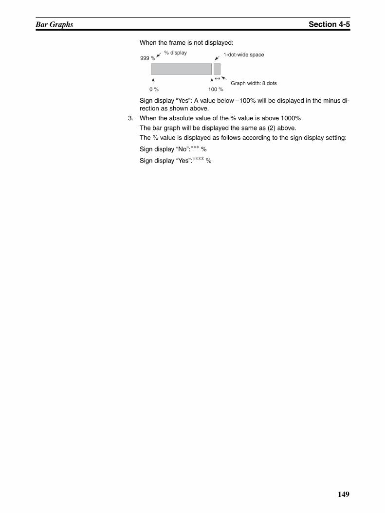
Bar Graphs Section 4-5
When the frame is not displayed:
Sign display “Yes”: A value below –100% will be displayed in the minus di-rection as shown above.
3. When the absolute value of the % value is above 1000%
The bar graph will be displayed the same as (2) above.
The % value is displayed as follows according to the sign display setting:
Sign display “No”:*** %
Sign display “Yes”:**** %
% display
0 % 100 %
999 %
Graph width: 8 dots↔
1-dot-wide space
149
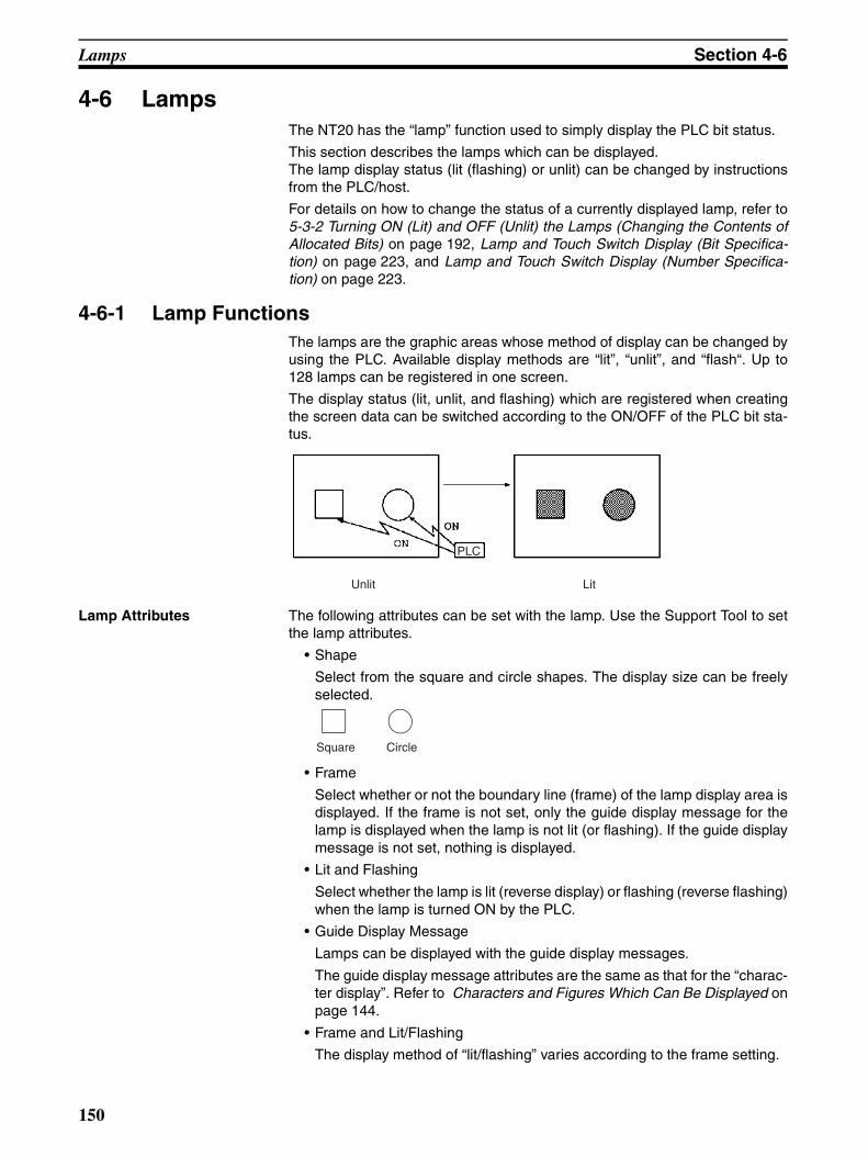
Lamps Section 4-6
4-6 LampsThe NT20 has the “lamp” function used to simply display the PLC bit status.
This section describes the lamps which can be displayed.The lamp display status (lit (flashing) or unlit) can be changed by instructionsfrom the PLC/host.
For details on how to change the status of a currently displayed lamp, refer to5-3-2 Turning ON (Lit) and OFF (Unlit) the Lamps (Changing the Contents ofAllocated Bits) on page 192, Lamp and Touch Switch Display (Bit Specifica-tion) on page 223, and Lamp and Touch Switch Display (Number Specifica-tion) on page 223.
4-6-1 Lamp FunctionsThe lamps are the graphic areas whose method of display can be changed byusing the PLC. Available display methods are “lit”, “unlit”, and “flash“. Up to128 lamps can be registered in one screen.
The display status (lit, unlit, and flashing) which are registered when creatingthe screen data can be switched according to the ON/OFF of the PLC bit sta-tus.
Lamp Attributes The following attributes can be set with the lamp. Use the Support Tool to setthe lamp attributes.
• Shape
Select from the square and circle shapes. The display size can be freelyselected.
• Frame
Select whether or not the boundary line (frame) of the lamp display area isdisplayed. If the frame is not set, only the guide display message for thelamp is displayed when the lamp is not lit (or flashing). If the guide displaymessage is not set, nothing is displayed.
• Lit and Flashing
Select whether the lamp is lit (reverse display) or flashing (reverse flashing)when the lamp is turned ON by the PLC.
• Guide Display Message
Lamps can be displayed with the guide display messages.
The guide display message attributes are the same as that for the “charac-ter display”. Refer to Characters and Figures Which Can Be Displayed onpage 144.
• Frame and Lit/Flashing
The display method of “lit/flashing” varies according to the frame setting.
Unlit Lit
PLC
Square Circle
150
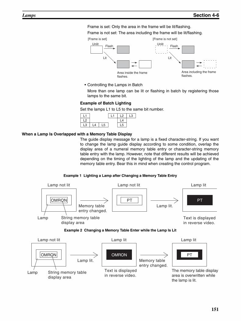
Lamps Section 4-6
Frame is set: Only the area in the frame will be lit/flashing.
Frame is not set: The area including the frame will be lit/flashing.
• Controlling the Lamps in Batch
More than one lamp can be lit or flashing in batch by registering thoselamps to the same bit.
Example of Batch Lighting
Set the lamps L1 to L5 to the same bit number.
When a Lamp Is Overlapped with a Memory Table DisplayThe guide display message for a lamp is a fixed character-string. If you wantto change the lamp guide display according to some condition, overlap thedisplay area of a numeral memory table entry or character-string memorytable entry with the lamp. However, note that different results will be achieveddepending on the timing of the lighting of the lamp and the updating of thememory table entry. Bear this in mind when creating the control program.
Example 1 Lighting a Lamp after Changing a Memory Table Entry
Example 2 Changing a Memory Table Enter while the Lamp Is Lit
[Frame is set]
UnlitFlash
Lit
[Frame is not set]
UnlitFlash
Lit
Area inside the frame flashes.
Area including the frame flashes.
L1L2L3 L4 L5
L1 L2 L3L4L5
OMRON PTMemory table entry changed.
Lamp lit.PT
Lamp String memory tabledisplay area
Text is displayedin reverse video.
Lamp not lit Lamp not lit Lamp lit
OMRONMemory table entry changed.
Lamp lit.
Lamp String memory tabledisplay area
The memory table displayarea is overwritten whilethe lamp is lit.
Text is displayedin reverse video.
OMRON PT
Lamp not lit Lamp lit Lamp lit
151
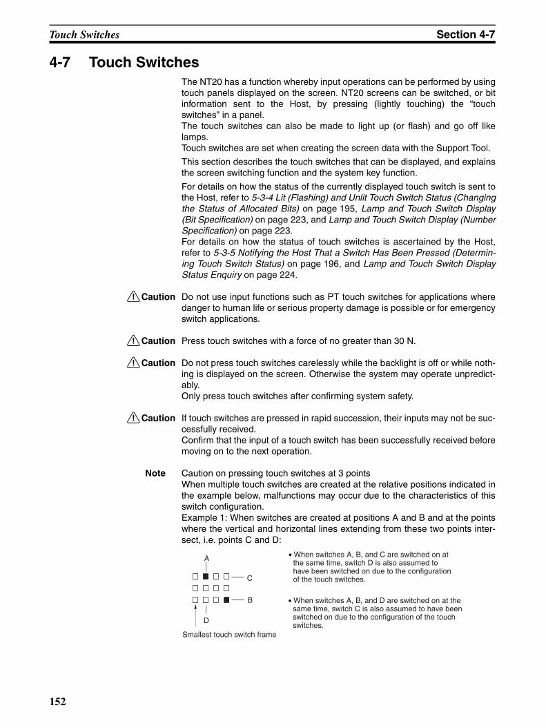
Touch Switches Section 4-7
4-7 Touch SwitchesThe NT20 has a function whereby input operations can be performed by usingtouch panels displayed on the screen. NT20 screens can be switched, or bitinformation sent to the Host, by pressing (lightly touching) the “touchswitches” in a panel.The touch switches can also be made to light up (or flash) and go off likelamps.Touch switches are set when creating the screen data with the Support Tool.
This section describes the touch switches that can be displayed, and explainsthe screen switching function and the system key function.
For details on how the status of the currently displayed touch switch is sent tothe Host, refer to 5-3-4 Lit (Flashing) and Unlit Touch Switch Status (Changingthe Status of Allocated Bits) on page 195, Lamp and Touch Switch Display(Bit Specification) on page 223, and Lamp and Touch Switch Display (NumberSpecification) on page 223.For details on how the status of touch switches is ascertained by the Host,refer to 5-3-5 Notifying the Host That a Switch Has Been Pressed (Determin-ing Touch Switch Status) on page 196, and Lamp and Touch Switch DisplayStatus Enquiry on page 224.
!Caution Do not use input functions such as PT touch switches for applications wheredanger to human life or serious property damage is possible or for emergencyswitch applications.
!Caution Press touch switches with a force of no greater than 30 N.
!Caution Do not press touch switches carelessly while the backlight is off or while noth-ing is displayed on the screen. Otherwise the system may operate unpredict-ably.Only press touch switches after confirming system safety.
!Caution If touch switches are pressed in rapid succession, their inputs may not be suc-cessfully received.Confirm that the input of a touch switch has been successfully received beforemoving on to the next operation.
Note Caution on pressing touch switches at 3 pointsWhen multiple touch switches are created at the relative positions indicated inthe example below, malfunctions may occur due to the characteristics of thisswitch configuration.Example 1: When switches are created at positions A and B and at the pointswhere the vertical and horizontal lines extending from these two points inter-sect, i.e. points C and D:
A
C
B
D
Smallest touch switch frame
• When switches A, B, and C are switched on at the same time, switch D is also assumed to have been switched on due to the configuration of the touch switches.
• When switches A, B, and D are switched on at the same time, switch C is also assumed to have been switched on due to the configuration of the touch switches.
152

Touch Switches Section 4-7
4-7-1 Functions of Touch SwitchesTouch switches are created using rectangular elements measuring 19 dotshorizontally by 19 dots vertically. A touch switch can comprise more than onetouch switch element. Up to 72 touch switches (12 horizontally x 6 vertically)can be registered on one screen.
• Functions of Touch Switches
Touch switches can have the following functions:
• PLC notification function:
Host link/NT link/C200H direct communications (page 196)
RS-232C (NT20-ST128) (page 224)
• Screen switch function (page 154)
• System key function (page 154)
• Numeral setting function:
Host link/NT link/C200H direct communications (page 199)
RS-232C (NT20-ST128) (page 224)
Touch Switch Attributes The following attributes can be set for touch switches.
• Display Frame
The area that will respond as a touch switch is displayed in the form of aframe, as shown in the table below. One of three types of frame - standard,3-D, and none - can be selected.
If “none” is selected, only the touch switch’s guide display message (ornothing, if there is none) are displayed until a “light” or “flash” designationis sent from the PLC/Host or the touch switch is pressed.
• Inverse Display on Input
It is possible to set a touch switch so that its display will be inverted whenit is pressed.
• Lighting and Flashing
19 dots
19 dots
PLC
When the touch switch is pressed, bit information is sent to the PLC. (Host link/NT link)
A touch switch can comprise more than one touch switch element.
Host
When the touch switch is pressed, the touch switch number or bit information is sent to the Host (RS-232C).
Type of Display Frame Switch OFF Switch ON
Standard
3-D
None
153
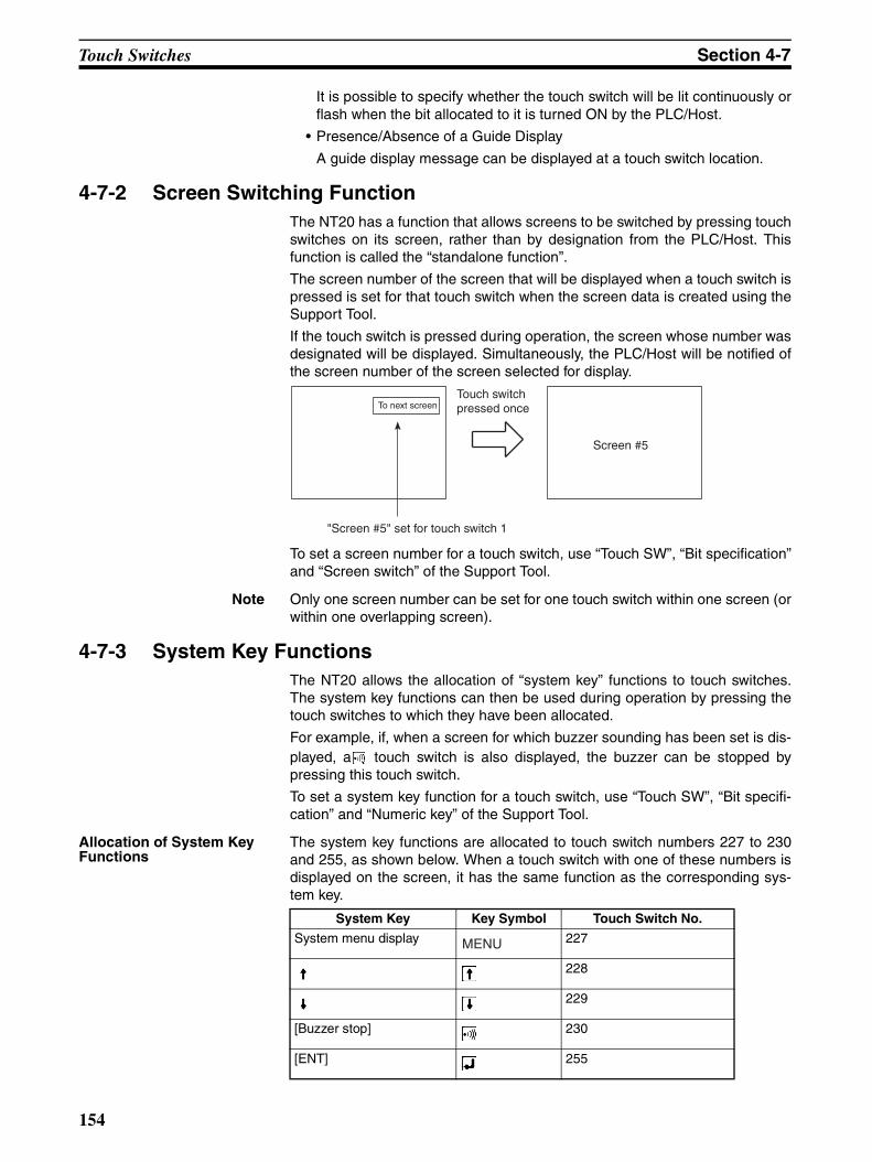
Touch Switches Section 4-7
It is possible to specify whether the touch switch will be lit continuously orflash when the bit allocated to it is turned ON by the PLC/Host.
• Presence/Absence of a Guide Display
A guide display message can be displayed at a touch switch location.
4-7-2 Screen Switching FunctionThe NT20 has a function that allows screens to be switched by pressing touchswitches on its screen, rather than by designation from the PLC/Host. Thisfunction is called the “standalone function”.
The screen number of the screen that will be displayed when a touch switch ispressed is set for that touch switch when the screen data is created using theSupport Tool.
If the touch switch is pressed during operation, the screen whose number wasdesignated will be displayed. Simultaneously, the PLC/Host will be notified ofthe screen number of the screen selected for display.
To set a screen number for a touch switch, use “Touch SW”, “Bit specification”and “Screen switch” of the Support Tool.
Note Only one screen number can be set for one touch switch within one screen (orwithin one overlapping screen).
4-7-3 System Key FunctionsThe NT20 allows the allocation of “system key” functions to touch switches.The system key functions can then be used during operation by pressing thetouch switches to which they have been allocated.
For example, if, when a screen for which buzzer sounding has been set is dis-played, a touch switch is also displayed, the buzzer can be stopped bypressing this touch switch.
To set a system key function for a touch switch, use “Touch SW”, “Bit specifi-cation” and “Numeric key” of the Support Tool.
Allocation of System Key Functions
The system key functions are allocated to touch switch numbers 227 to 230and 255, as shown below. When a touch switch with one of these numbers isdisplayed on the screen, it has the same function as the corresponding sys-tem key.
"Screen #5" set for touch switch 1
To next screen
Screen #5
Touch switch pressed once
System Key Key Symbol Touch Switch No.
System menu display 227
228
229
[Buzzer stop] 230
[ENT] 255
MENU
154

Touch Switches Section 4-7
When a touch switch to which a system key function has been allocated ispressed, the PLC is not notified of the touch switch bit information.
The , , and keys are not displayed among the system numeric keys.
Accordingly, when using the system numeric keys, create the , , andkeys. Alternatively, create user numeric keys.
155

Numeral Setting Section 4-8
4-8 Numeral SettingThe NT20 has a “numeral setting” function to enable numerical values to beinput from the screen. This function inputs numerical values to numeral mem-ory table entries in response to touch switch operations, displays thesenumerical values on the screen, and sends them to the host.
This section outlines the numeral setting function and the method for creatingthe ten keys required to set numerical values on the screen, and explains howto use ten keys during operation.
Numeral setting screens cannot be registered as child screens of continuousscreens. In the case of overlapping screens, only one of the screens can beset as a numeral setting screen.
For details on the actual methods used to ascertain input numerical values atthe PLC, refer to 5-3-6 Notification of Numbers to the PLC on page 199, andFour-digit Number Input Notify and Eight-digit Number Input Notify onpage 225.Numeral settings are set during screen creation with the Support Tool.
!Caution Confirm system safety carefully before changing monitor data.
4-8-1 The Numeral Setting FunctionThe numeral setting function is described below.
Basic Procedure The procedure for numeral setting is as follows.
1,2,3... 1. Input the numerical value at the touch panel.
2. The input numerical value is displayed in the numeral setting area on thescreen.
3. Confirm the input numerical value; it will be written to the numeral memorytable, and the PLC will be simultaneously notified.
Restrictions on Numerical Value Input and Attribute SettingNumerical values of up to 8 digits (7 if there is a minus sign) can be input ineither decimal or hexadecimal format.
• Decimal Input
When the display attribute is set for decimal display, values are input in thedecimal format.
• Numerical Value RangeThe range for numerical values that can be input differs according towhether or not there is a sign display.
When there is no sign display: 0 to 99999999 (8 digits)
When there is a sign display: –9999999 to +99999999 (7 digits for negative numbers, 8 digits for positive numbers)
Input
Write Notification
1 2 3 4 1 2 3 4
NT20
PLC
Touch switch
Numeral setting area
Numeral memory table
156

Numeral Setting Section 4-8
If a sign is displayed when using the thumbwheel type of numeral set-ting, the maximum number of digits for both positive and negative num-bers is 7.
• Decimal PointA maximum of 7 digits can be input after the decimal point (or 6 fornegative numbers).
• Hexadecimal Input
When the display attribute is set for hexadecimal display, values are inputin the hexadecimal format.
• Numerical Value RangeNumerical values can be input in the range 0 to FFFFFFFF (8 digits).
• Attributes That Can Be Set
The attributes of the numerical values displayed in the input field are thesame as for numeral displays. Refer to Numerals Which Can Be Displayedon page 145.
Upper/Lower Limit CheckWhen direct connection is used with an NT20, upper and lower limits can beset for input numerical values to prevent erroneous values that are outside thevalid range being stored in the numeral memory table or sent to the PLC.The upper/lower limit check is executed when the input numerical value hasbeen confirmed: if the value is outside the valid range, the screen returns to itsstatus before input.
Note In order to use the numerical value input setting safely, always use the upper/lower limit check function. (This function is not supported by the NT20-ST128.Take appropriate measures using the user application software.)
4-8-2 Types of Numeral SettingThere are two types of numeral setting: the numeric key type, and the thumb-wheel type. The basic function of these two types is the same, but the screendisplays and input methods are different.
A maximum of 50 input fields, including both numeric key and thumbwheeltypes, can be registered on one screen.
Numeric Key TypeWhen a numerical value is input using touch switches to which numeric key functions have been allocated, the
input numerical value is displayed on the screen. On pressing the return key after completing input, the inputnumerical value is written to the numeral memory table and sent to the host.
If there is more than one numeral setting input field, the field in which the input is to be made can also be se-lected with the numeric keys.
In order to perform numeric key input, it is necessary not only to create a numeral setting input field on thescreen, but also to create the numeric keys to be used for input. (Refer to 4-8-4 Using Numeric Keys).
Displayed in the numeral setting input field
Input
Input the numerical value using the numeric keys on the screen.
WriteNotification
Numeral memory table
On pressing the key, the input value is written to the numeral memory table and the PLC will be notified simultaneously.
1 2 3 4 1 2 3 4 Host
NT20
157

Numeral Setting Section 4-8
Thumbwheel Type (Direct Connection Only)When using an NT20 with a direct connection, numerical values are inputdirectly at the numeral setting input field using touch switches that incrementor decrement each of the digits in the display when pressed. Each time thedisplayed numerical value is changed, the new displayed value is written tothe numeral memory table and the host is simultaneously notified.This means that, when using the Thumbwheel type of numeral setting, all thatis required to input numerical values is to create the numeral setting input fieldon the screen.
4-8-3 Creating Numeric KeysIn order to input numerical values using the numeral setting function, apartfrom the display area for the numeral setting, the numeric keys must also becreated.
Setting Screen Attributes The type of numeric keys can be selected using the numeral setting attributesof the screen attributes. There are two numeral setting attributes: “system”and “user”.
• Screen When “System” Is Specified
When a numeral setting area is created, numeric keys are automaticallydisplayed. The display position and arrangement of the numeric keys arefixed. On this screen, only the types of numeric key shown in the figure be-low (system keys) are used.
When using the NT20 with the numeral setting attribute set to “system”,apart from the numeric keys provided by the system, the touch switchesallocated to system keys ( , , ) also have to be created (system keyfunction). To enable input of hexadecimal values, it is also necessary tocreate numeric keys A through F.
With the NT20, if the numeral setting attribute is set to “system”, apart fromthe numeric keys prepared by the system, the touch switches allocated tosystem keys ( , , ) have to be created. (Refer to 4-7-3 System KeyFunctions on page 154.)
• When the Numeral Setting Attribute Is “User”
WriteNotification
1 2 3 4 1 2 3 4 Host
NT20Pressing the [−] key decrements the digit by one.
Pressing the [+] key increments the digit by one.
Each time a [+] or [−] key is pressed, the input value is written to the numeral memory table and the host is simultaneously notified.
Numeral memory table
Tank A Tank B Tank C
1 2 3 4 5 67 8 9 0 CLR ±
158
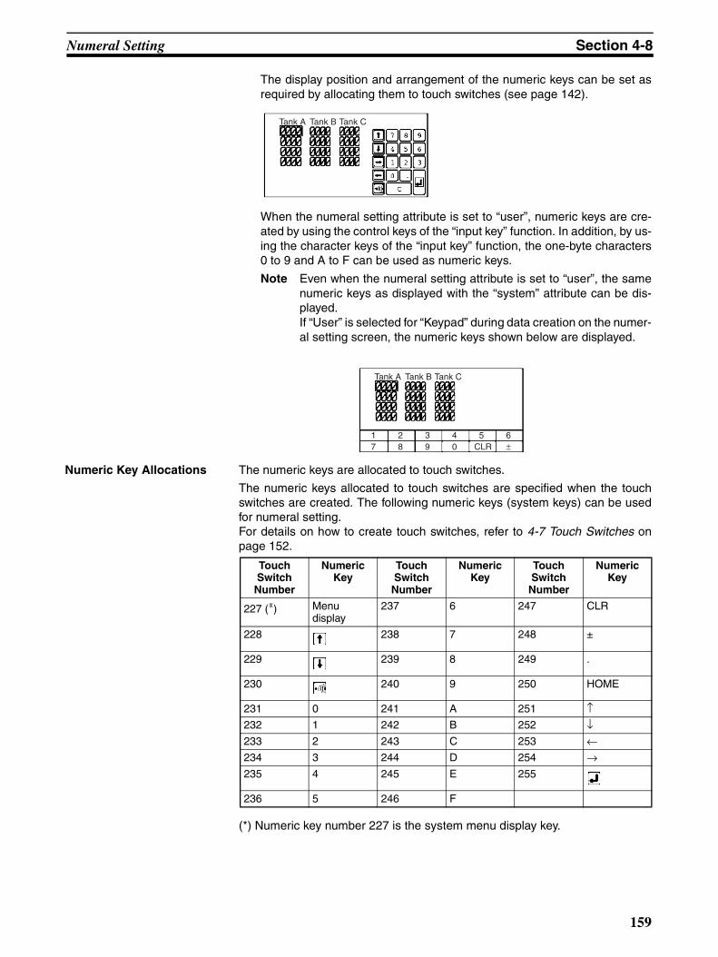
Numeral Setting Section 4-8
The display position and arrangement of the numeric keys can be set asrequired by allocating them to touch switches (see page 142).
When the numeral setting attribute is set to “user”, numeric keys are cre-ated by using the control keys of the “input key” function. In addition, by us-ing the character keys of the “input key” function, the one-byte characters0 to 9 and A to F can be used as numeric keys.
Note Even when the numeral setting attribute is set to “user”, the samenumeric keys as displayed with the “system” attribute can be dis-played.If “User” is selected for “Keypad” during data creation on the numer-al setting screen, the numeric keys shown below are displayed.
Numeric Key Allocations The numeric keys are allocated to touch switches.
The numeric keys allocated to touch switches are specified when the touchswitches are created. The following numeric keys (system keys) can be usedfor numeral setting.For details on how to create touch switches, refer to 4-7 Touch Switches onpage 152.
(*) Numeric key number 227 is the system menu display key.
Tank A Tank B Tank C
Tank A Tank B Tank C
1 2 3 4 5 67 8 9 0 CLR ±
Touch Switch
Number
NumericKey
Touch Switch
Number
NumericKey
Touch Switch
Number
NumericKey
227 (*) Menudisplay
237 6 247 CLR
228 238 7 248 ±
229 239 8 249 .
230 240 9 250 HOME
231 0 241 A 251 ↑232 1 242 B 252 ↓233 2 243 C 253 ←234 3 244 D 254 →235 4 245 E 255
236 5 246 F
159
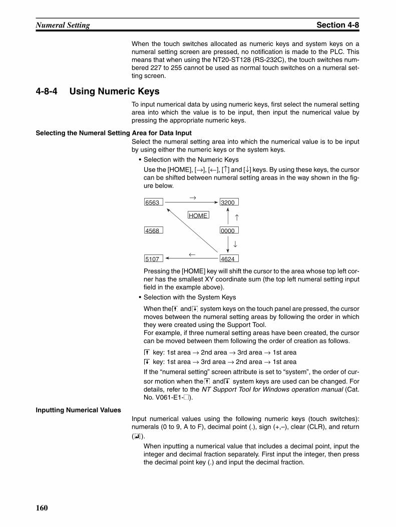
Numeral Setting Section 4-8
When the touch switches allocated as numeric keys and system keys on anumeral setting screen are pressed, no notification is made to the PLC. Thismeans that when using the NT20-ST128 (RS-232C), the touch switches num-bered 227 to 255 cannot be used as normal touch switches on a numeral set-ting screen.
4-8-4 Using Numeric KeysTo input numerical data by using numeric keys, first select the numeral settingarea into which the value is to be input, then input the numerical value bypressing the appropriate numeric keys.
Selecting the Numeral Setting Area for Data InputSelect the numeral setting area into which the numerical value is to be inputby using either the numeric keys or the system keys.
• Selection with the Numeric Keys
Use the [HOME], [→], [←], [↑] and [↓] keys. By using these keys, the cursorcan be shifted between numeral setting areas in the way shown in the fig-ure below.
Pressing the [HOME] key will shift the cursor to the area whose top left cor-ner has the smallest XY coordinate sum (the top left numeral setting inputfield in the example above).
• Selection with the System Keys
When the and system keys on the touch panel are pressed, the cursormoves between the numeral setting areas by following the order in whichthey were created using the Support Tool.For example, if three numeral setting areas have been created, the cursorcan be moved between them following the order of creation as follows.
key: 1st area → 2nd area → 3rd area → 1st area key: 1st area → 3rd area → 2nd area → 1st area
If the “numeral setting” screen attribute is set to “system”, the order of cur-sor motion when the and system keys are used can be changed. Fordetails, refer to the NT Support Tool for Windows operation manual (Cat.No. V061-E1-@).
Inputting Numerical ValuesInput numerical values using the following numeric keys (touch switches):numerals (0 to 9, A to F), decimal point (.), sign (+,–), clear (CLR), and return( ).
When inputting a numerical value that includes a decimal point, input theinteger and decimal fraction separately. First input the integer, then pressthe decimal point key (.) and input the decimal fraction.
6563
4568
5107
3200
0000
4624
HOME
→
↑
↑
←
160
Numeral Setting Section 4-8
If the integer or decimal fraction exceed their respective allowable numbersof display digits, they are shifted to the left. In the system keys, however,the decimal point key (.) is not included. Therefore, it is necessary to createthe decimal point key (.) apart from the ten keys of the system keys to inputa numerical value including decimal fraction.
• Changing the Sign
When there is a sign display, pressing the sign (±) key changes minus toplus or plus to minus.
• Confirming Input Numerical Values
Always press the return key as the final step when inputting a numericalvalue. When the return key is pressed, the displayed numerical value iswritten to the numeral memory table and at the same time the host is noti-fied.
• Initial Operation of Input Keys
The sign key (±), decimal point key (.), and alphabet key (A to F), operateas follows on initial use (first use after displaying the screen).
• Sign Key (±)
The display is cleared to zero (assuming decimal input with sign dis-play).
• Decimal Point Key (.)
The display is cleared to zero, after which input starts from the decimalfraction digits (assuming decimal input with sign display).
• Alphabet Keys (A to F)
The display is cleared to zero (assuming decimal input).
• Upper/Lower Limit Check
When the return key is pressed after inputting a numerical value, an upper/lower limit check is executed. If the input numerical value is outside the val-id range, the data in the numeral memory table before input is redisplayedand the host is not notified.
4-8-5 Using The Thumbwheel Type of Numeral SettingWhen using the thumbwheel type of numeral setting, numerical values areinput by directly touching the incrementing/decrementing (+/–) keys.
Numerical Value Input Input numerical values by using the incrementing/decrementing (+, –) keysprovided for each digit.
• Numerical Value Specification
161
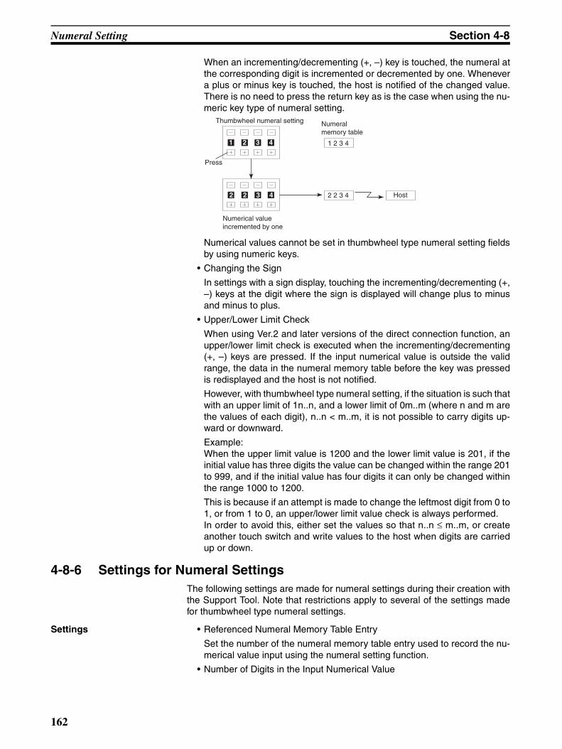
Numeral Setting Section 4-8
When an incrementing/decrementing (+, –) key is touched, the numeral atthe corresponding digit is incremented or decremented by one. Whenevera plus or minus key is touched, the host is notified of the changed value.There is no need to press the return key as is the case when using the nu-meric key type of numeral setting.
Numerical values cannot be set in thumbwheel type numeral setting fieldsby using numeric keys.
• Changing the Sign
In settings with a sign display, touching the incrementing/decrementing (+,–) keys at the digit where the sign is displayed will change plus to minusand minus to plus.
• Upper/Lower Limit Check
When using Ver.2 and later versions of the direct connection function, anupper/lower limit check is executed when the incrementing/decrementing(+, –) keys are pressed. If the input numerical value is outside the validrange, the data in the numeral memory table before the key was pressedis redisplayed and the host is not notified.
However, with thumbwheel type numeral setting, if the situation is such thatwith an upper limit of 1n..n, and a lower limit of 0m..m (where n and m arethe values of each digit), n..n < m..m, it is not possible to carry digits up-ward or downward.
Example:When the upper limit value is 1200 and the lower limit value is 201, if theinitial value has three digits the value can be changed within the range 201to 999, and if the initial value has four digits it can only be changed withinthe range 1000 to 1200.
This is because if an attempt is made to change the leftmost digit from 0 to1, or from 1 to 0, an upper/lower limit value check is always performed.In order to avoid this, either set the values so that n..n ≤ m..m, or createanother touch switch and write values to the host when digits are carriedup or down.
4-8-6 Settings for Numeral SettingsThe following settings are made for numeral settings during their creation withthe Support Tool. Note that restrictions apply to several of the settings madefor thumbwheel type numeral settings.
Settings • Referenced Numeral Memory Table Entry
Set the number of the numeral memory table entry used to record the nu-merical value input using the numeral setting function.
• Number of Digits in the Input Numerical Value
Thumbwheel numeral setting
1 2 3 41 2 3 4
Press
2 2 3 4 2 2 3 4 Host
Numerical value incremented by one
Numeral memory table
162

Numeral Setting Section 4-8
Set the number of digits in the numerical values that can be input. A max-imum of 8 digits (total of integer and decimal fraction parts) can be set.However, if there is a sign display, the maximum number of digits for neg-ative values will be seven.
• Upper/Lower Limits
Set the upper limit and lower limit separately. The maximum number of dig-its in the set values is eight (or seven if there is a sign display).
When the upper limit value and lower limit value are set as negative values,set “F” as the eighth digit.Example: Upper limit value or lower limit value is “–123” → F0000123.
• Display Attributes
Set attributes in the same way as for numeral display. For details, see Nu-merals Which Can Be Displayed on page 145.
Restrictions and Additional Settings for Thumbwheel Type Numeral SettingsThere are the following restrictions and additional items to set when creatingthumbwheel type numeral settings.
• Number of Input Digits for Positive Values When There Is a Sign Display
When a sign display is set for a thumbwheel type numeral setting, a max-imum of 7 digits can be input for positive values.
• Display Size
One of two sizes can be selected: “small” in which each digit comprisestwo touch switch units, and “medium”, in which each digit comprises threetouch switch units. Note that if “small” is selected the area in which the nu-merical value is displayed is also the touch switch input area.
• Shape (End Plates)
Set which of the two shapes shown below will be used. One has “endplates” at right and left sides and the other does not.
• Restrictions on Display Attributes
The following restrictions apply to display attributes.
Character type: Wide size onlyCharacter enlargement: Standard only,
regardless of the display size specificationZero suppress: No zero suppression only
Refer to Numerals Which Can Be Displayed on page 145.
With Without
0 0 0 0 0 0 0 0 0000 0000
163

Numeral Setting Section 4-8
164
SECTION 5How to Use the Host Link/NT Link
This Section describes in concrete terms how to use the Host link/NT link communications with the NT20.
5-1 Overview of Direct Connection Operations . . . . . . . . . . . . . . . . . . . . . . . . . . 166
5-1-1 Equipment and Settings Used in This Section . . . . . . . . . . . . . . . . . 166
5-1-2 Allocatable Bits and Words . . . . . . . . . . . . . . . . . . . . . . . . . . . . . . . 166
5-1-3 NT20 Status Control and Notification to PLC . . . . . . . . . . . . . . . . . 167
5-1-4 Switching the Screen Display. . . . . . . . . . . . . . . . . . . . . . . . . . . . . . 172
5-1-5 Notifying the PLC of the Display Screen(to Display the Number of Currently Displayed Screen) . . . . . . . . . 174
5-2 Memory Tables and Bar Graphs . . . . . . . . . . . . . . . . . . . . . . . . . . . . . . . . . . . 177
5-2-1 Displaying the Contents of Allocated Words of Memory Table Entries 180
5-2-2 Changing Displayed Numerals or Character Strings(Changing the Contents of Allocated Words ... Direct Specification) 182
5-2-3 Changing Displayed Numerical Values or Character Strings (Changing the Contents of Allocated Words ... Indirect Specification) 184
5-2-4 Copying Memory Table Entries . . . . . . . . . . . . . . . . . . . . . . . . . . . . 186
5-2-5 Upgrading Bar Graphs (Changing the Contents of Allocated Words) 189
5-3 Lamps, Touch Switches, Numeral Setting . . . . . . . . . . . . . . . . . . . . . . . . . . . 191
5-3-1 Allocation Bits and Display of Lamps . . . . . . . . . . . . . . . . . . . . . . . 191
5-3-2 Turning ON (Lit) and OFF (Unlit) the Lamps(Changing the Contents of Allocated Bits). . . . . . . . . . . . . . . . . . . . 192
5-3-3 Allocated Bits and Display of Touch Switches . . . . . . . . . . . . . . . . 193
5-3-4 Lit (Flashing) and Unlit Touch Switch Status(Changing the Status of Allocated Bits) . . . . . . . . . . . . . . . . . . . . . . 195
5-3-5 Notifying the Host That a Switch Has Been Pressed(Determining Touch Switch Status) . . . . . . . . . . . . . . . . . . . . . . . . . 196
5-3-6 Notification of Numbers to the PLC. . . . . . . . . . . . . . . . . . . . . . . . . 199
5-4 NT20 Status Control . . . . . . . . . . . . . . . . . . . . . . . . . . . . . . . . . . . . . . . . . . . . 203
5-4-1 Controllable NT20 Functions . . . . . . . . . . . . . . . . . . . . . . . . . . . . . . 203
5-4-2 How to Control NT20 Functions . . . . . . . . . . . . . . . . . . . . . . . . . . . 205
5-5 Notification of the Operating Status to the PLC(Determining the NT20 Operating Status) . . . . . . . . . . . . . . . . . . . . . . . . . . . 208
5-5-1 Ascertainable NT20 Status (Notified Operating Status) . . . . . . . . . 208
5-5-2 Reading the NT20 Operating Status . . . . . . . . . . . . . . . . . . . . . . . . . 209
165

Overview of Direct Connection Operations Section 5-1
5-1 Overview of Direct Connection OperationsThis section explains allocated bits and words, control of the NT20 and PLCnotification methods, and the actual procedures used for switching screens,thereby providing the basic information required to use the NT20-ST121-Ehost link, or NT link.
5-1-1 Equipment and Settings Used in This SectionThe following equipment and settings are used in the examples in this section:
Equipment PT: NT20-ST121-E
PLC: CQM1H
Support Tool: NT Support Tool for Windows Ver. 4.8
Support Tool Settings
PT Model: NT20
PLC Vendor: OMRON
5-1-2 Allocatable Bits and WordsWhen the host link/NT link is used, the following bits and words are allocatedto the PLC and used for the NT20 operation. The range of respective areavaries with the type of PLC.
The allocations must be made without exceeding respective area range.
OMRON PLCs
: OK : 1 word only ×: NG
Symbol CS/CJ Series PLCs
Area Name Allocated Bit
Allocated Word
Numeral Character String
None CIO Area
H HR Area
A AR Area
LR LR Area (See note 1.)
T TC AreaTimer PVs
×
TU TC AreaTimer Completion Flags
× × ×
C TC area,Counter PVs
×
CU TC area,Counter Completion Flags
× × ×
W WR
TK Task Flags × × ×D DM Area
E EM AreaCurrent bank
E0_ to EC_ EM AreaEM banks 0 to C
166
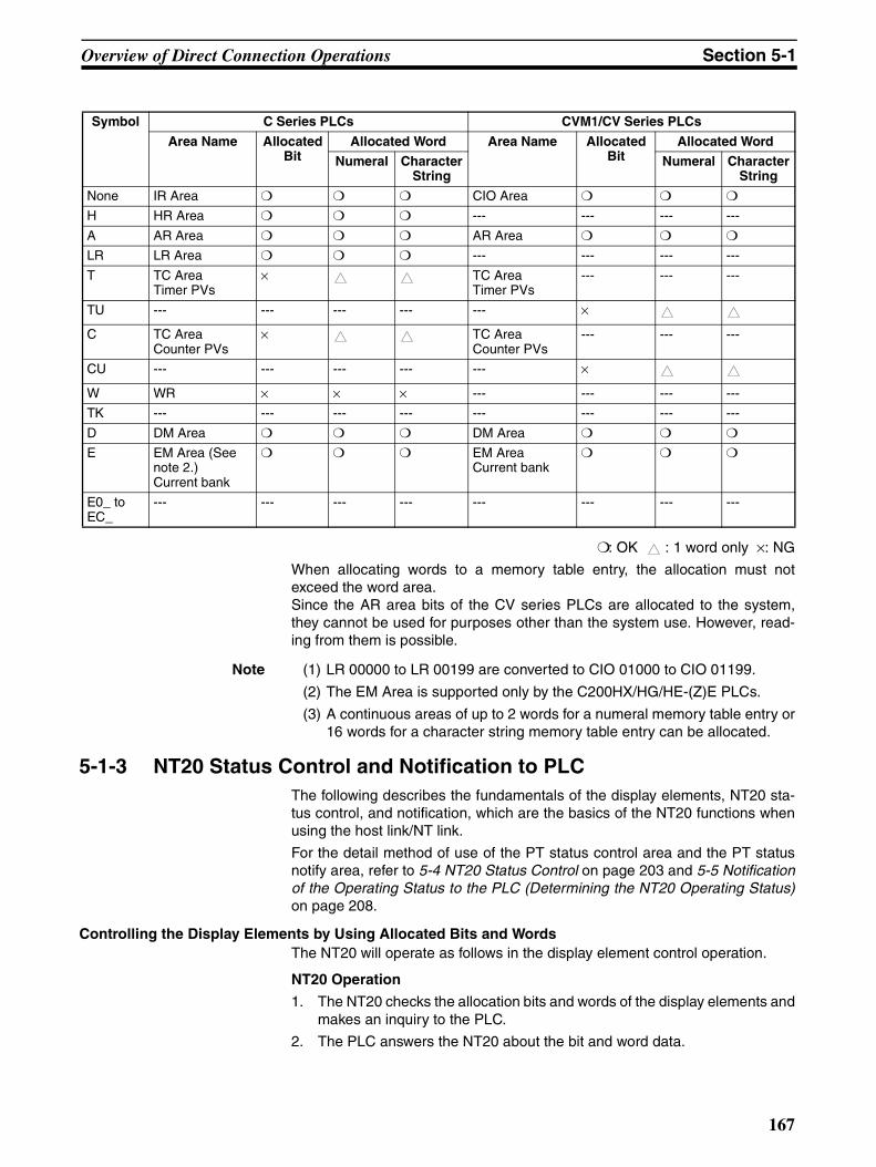
Overview of Direct Connection Operations Section 5-1
: OK : 1 word only ×: NG
When allocating words to a memory table entry, the allocation must notexceed the word area.Since the AR area bits of the CV series PLCs are allocated to the system,they cannot be used for purposes other than the system use. However, read-ing from them is possible.
Note (1) LR 00000 to LR 00199 are converted to CIO 01000 to CIO 01199.
(2) The EM Area is supported only by the C200HX/HG/HE-(Z)E PLCs.
(3) A continuous areas of up to 2 words for a numeral memory table entry or16 words for a character string memory table entry can be allocated.
5-1-3 NT20 Status Control and Notification to PLCThe following describes the fundamentals of the display elements, NT20 sta-tus control, and notification, which are the basics of the NT20 functions whenusing the host link/NT link.
For the detail method of use of the PT status control area and the PT statusnotify area, refer to 5-4 NT20 Status Control on page 203 and 5-5 Notificationof the Operating Status to the PLC (Determining the NT20 Operating Status)on page 208.
Controlling the Display Elements by Using Allocated Bits and WordsThe NT20 will operate as follows in the display element control operation.
NT20 Operation
1. The NT20 checks the allocation bits and words of the display elements andmakes an inquiry to the PLC.
2. The PLC answers the NT20 about the bit and word data.
Symbol C Series PLCs CVM1/CV Series PLCs
Area Name Allocated Bit
Allocated Word Area Name Allocated Bit
Allocated Word
Numeral Character String
Numeral Character String
None IR Area CIO Area
H HR Area --- --- --- ---
A AR Area AR Area
LR LR Area --- --- --- ---
T TC AreaTimer PVs
× TC AreaTimer PVs
--- --- ---
TU --- --- --- --- --- ×
C TC AreaCounter PVs
× TC AreaCounter PVs
--- --- ---
CU --- --- --- --- --- ×
W WR × × × --- --- --- ---
TK --- --- --- --- --- --- --- ---
D DM Area DM Area
E EM Area (See note 2.)Current bank
EM AreaCurrent bank
E0_ to EC_
--- --- --- --- --- --- --- ---
167

Overview of Direct Connection Operations Section 5-1
3. The NT20 changes the display status according to the bits and words ob-tained from the PLC.
NT20 Operation Example
Controlling the NT20 Status by Using Allocated Bits and Words ..... PT Status Control Area (PLC to PT)The PT status control area (PLC to PT) is provided to control the NT20 statusfrom the PLC. When data is written to this area in the PLC, the NT20 will readthe data and operates according to the data. The PT status control area isconfigured as four consecutive words as shown below.
The first word (word n) of the PT status control area must be set with the Sup-port Tool.
• Screen Switch Settings (Refer to page 172.)
Specify the screen number to switch the screen displayed on the NT20.
• Copy Memory Table Settings (Refer to page 187.)
Specify the memory table entry number to copy the contents of a memorytable internally in the NT20.
Set the copy type to match the type of memory table entry to be copied:
0: Character-string memory table
1: Numeral memory table
• PT Status Control Bits (Refer to page 203.)
These bits are switched ON and OFF to control the NT20 buzzer and back-light.
Lamp #0
Bit 010012?
Character-string memory table entry 2 First word: DM0100 Number of saved words: 3
TIM003?
DM0100 to DM0102?
Bit 010012 NT20 PLC
("a", "b")("c", "d")("e", "f")
Numeral memory table entry 0First word: TIM003Number of saved words: 1
Word 15 14 13 12 11 10 9 8 7 6 5 4 3 2 1 0 Bit
PT status control
n
n+1
n+2
n+3
0
Copy type Copy destination memory table entry # (3-digit BCD)
Copy source memory table entry # (3-digit BCD)
PT status control bit
Screen # (4-digit BCD)
0 0
Copy memory table setting
Screen switch setting
168

Overview of Direct Connection Operations Section 5-1
The PT status control area (PLC to PT) can be allocated to the following PLCareas.
: OK ×: NG
Since the AR area bits of the CV series PLCs are allocated to the system,they cannot be used for purposes other than the system use.
Note (1) LR 00000 to LR 00199 are converted to CIO 01000 to CIO 01199.
(2) The EM Area is supported only by the C200HX/HG/HE-(Z)E PLCs.
Note Make sure there is no duplication in the PT status control area allocations andPT status notify area allocations.
Note When NT link (1:N) is set, the PT status control area must be set for each con-nected PT.
0 0 0
15 14 13 12 11 10 9 8 Bit
OFF
Item Controlled
Screen display (Note 1) ON OFF
ON OFF
Continuous buzzer
Intermittent buzzer
ON OFF
ON
1 (ON) 0 (OFF)
Backlight mode FlashON
Note 1: When "ON" is set for screen display, the backlight is on; when "OFF" is set for screen display, the backlight is off.
Note 2: Priority registration is only valid when NT link (1:N) is set.
Processing priority registration (Note 2)
n+3
Symbol C-series Alloca-tion
CVM1/CV -series Alloca-tion
CS/CJ-series Alloca-tion
None IR Area CIO Area CIO Area
H HR Area --- --- HR Area Not for Host Link
A AR Area AR Area × AR Area
L LR Area --- --- LR Area (See note 1.) Not for Host Link
T TC AreaTimer PVs
× TC AreaTimer PVs
× TC AreaTimer PVs
×
TU --- --- --- --- TC area,Timer Completion Flags
×
C TC AreaCounter PVs
× TC AreaCounter PVs
× TC AreaCounter PVs
×
CU --- --- --- --- TC area,Counter Completion Flags
×
W --- --- --- --- WR Not for Host Link
TK --- --- --- --- Task Flags ×D DM Area DM Area DM Area
E EM Area (See note 2.)
EM AreaCurrent bank
Not for Host Link
EM AreaCurrent bank
Not for Host Link
E0_to EC_ --- --- --- --- EM AreaEM bank 0 to C
Not for Host Link
169

Overview of Direct Connection Operations Section 5-1
Notification of the Display Elements by Using Allocated Bits and WordsThe NT20 will operate as follows in the display element notification operation.
NT20 Operation
The NT20 will write any changes in the contents of the numeral or character-string memory table entry being displayed or pressing of a touch switch to thebits and words area in the PLC.
NT20 Operation Example
Notification of the NT20 Status by Using Allocated Bits and Words ..... PT Status Notify Area (PT to PLC)
The PT status notify area (PT to PLC) is provided to notify the PLC of NT20status changes. When any NT20 status has changed, such change is writtento this area in the PLC, and the PLC will read the data from this area to checkthe NT20 status.
The PT status notify area is configured as three consecutive words as shownbelow.
The first word (word m) of the PT status notify area must be set with the Sup-port Tool.
• Currently Displayed Screen (refer to page 175)
The screen number displayed on the NT20 is written to this word.
Simultaneously, the PT status screen switch strobe flag is set to ON (1).After the PLC is notified, this flag reverts to OFF (0). Checking the statusof this flag will provide a simple method of checking if the NT20 display hasswitched.
• Upgraded Memory Table Entry (Refer to page 200.)
The number of the numeral memory table entry is written to the word whenthe numeral memory table contents change due to the touch switch oper-ation on the NT20.
As the number of the numeral table entry is written, the PT status numeralsetting strobe flag is simultaneously set ON (1). After the PLC is notified,this flag reverts to OFF (0). Checking the status of this flag will provide asimple method of checking if a number has been input from the NT20.Note that this function is not available with the character-string memory ta-ble.
• PT Status (Refer to page 208.)
The NT20 operation status and other information are written with the ONor OFF of the bits as shown below.
Numeral memory table entry 100
Copy
Bit 009012: ON
Numeral memory table entry 0Number of saved words: 1First word: DM0110
DM0110: 0432
NT20 PLC
0 4 3 2
Touch switch #12 Bit 009012
Screen being displayed
PT status
m
m+1
m+2
Word 15 14 13 12 11 10 9 8 7 6 5 4 3 2 1 0 Bit
0
Screen # (4-digit BCD)
PT status
Numeral memory table entry # (3-digit BCD)
0 0
Upgraded memory table entry
170
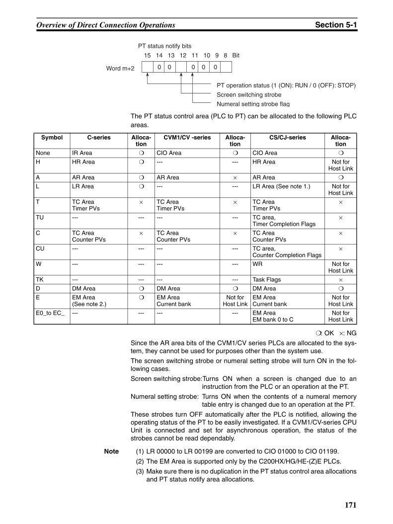
Overview of Direct Connection Operations Section 5-1
The PT status control area (PLC to PT) can be allocated to the following PLCareas.
: OK ×: NG
Since the AR area bits of the CVM1/CV series PLCs are allocated to the sys-tem, they cannot be used for purposes other than the system use.
The screen switching strobe or numeral setting strobe will turn ON in the fol-lowing cases.
Screen switching strobe:Turns ON when a screen is changed due to aninstruction from the PLC or an operation at the PT.
Numeral setting strobe: Turns ON when the contents of a numeral memorytable entry is changed due to an operation at the PT.
These strobes turn OFF automatically after the PLC is notified, allowing theoperating status of the PT to be easily investigated. If a CVM1/CV-series CPUUnit is connected and set for asynchronous operation, the status of thestrobes cannot be read dependably.
Note (1) LR 00000 to LR 00199 are converted to CIO 01000 to CIO 01199.
(2) The EM Area is supported only by the C200HX/HG/HE-(Z)E PLCs.
(3) Make sure there is no duplication in the PT status control area allocationsand PT status notify area allocations.
15 14 13 12 11 10 9 8 Bit
PT status notify bits
0 0 0 0 0Word m+2
PT operation status (1 (ON): RUN / 0 (OFF): STOP)
Screen switching strobe
Numeral setting strobe flag
Symbol C-series Alloca-tion
CVM1/CV -series Alloca-tion
CS/CJ-series Alloca-tion
None IR Area CIO Area CIO Area
H HR Area --- --- HR Area Not for Host Link
A AR Area AR Area × AR Area
L LR Area --- --- LR Area (See note 1.) Not for Host Link
T TC AreaTimer PVs
× TC AreaTimer PVs
× TC AreaTimer PVs
×
TU --- --- --- --- TC area,Timer Completion Flags
×
C TC AreaCounter PVs
× TC AreaCounter PVs
× TC AreaCounter PVs
×
CU --- --- --- --- TC area,Counter Completion Flags
×
W --- --- --- --- WR Not for Host Link
TK --- --- --- --- Task Flags ×D DM Area DM Area DM Area
E EM Area (See note 2.)
EM AreaCurrent bank
Not for Host Link
EM AreaCurrent bank
Not for Host Link
E0_to EC_ --- --- --- --- EM AreaEM bank 0 to C
Not for Host Link
171
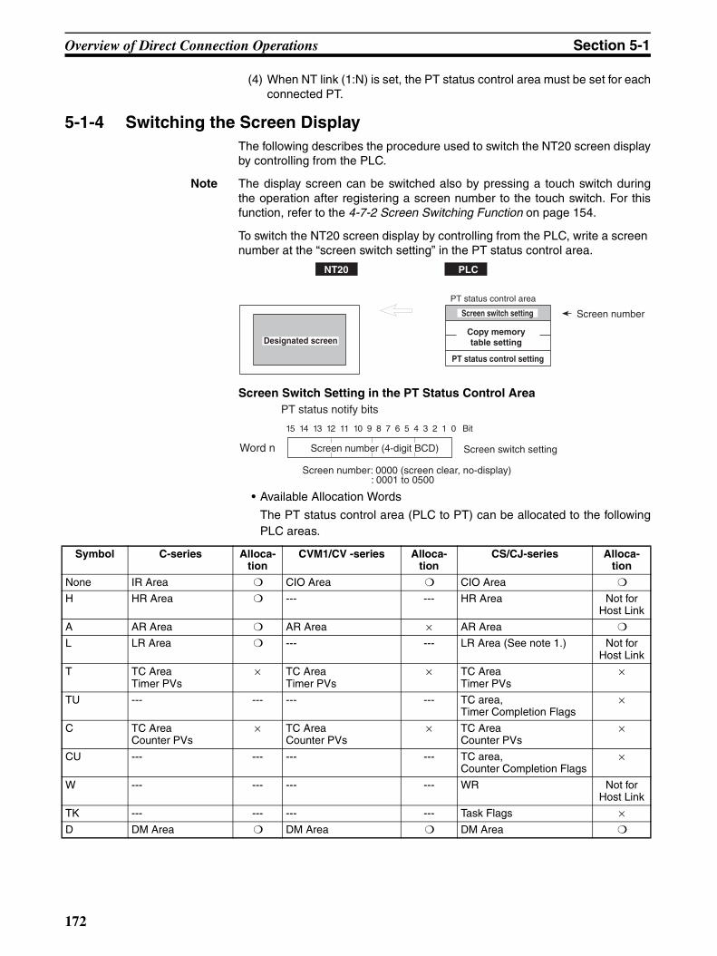
Overview of Direct Connection Operations Section 5-1
(4) When NT link (1:N) is set, the PT status control area must be set for eachconnected PT.
5-1-4 Switching the Screen DisplayThe following describes the procedure used to switch the NT20 screen displayby controlling from the PLC.
Note The display screen can be switched also by pressing a touch switch duringthe operation after registering a screen number to the touch switch. For thisfunction, refer to the 4-7-2 Screen Switching Function on page 154.
To switch the NT20 screen display by controlling from the PLC, write a screen number at the “screen switch setting” in the PT status control area.
Screen Switch Setting in the PT Status Control Area
• Available Allocation Words
The PT status control area (PLC to PT) can be allocated to the followingPLC areas.
NT20 PLC
Designated screen
PT status control area
Screen switch setting
PT status control setting
Screen number
Copy memory table setting
15 14 13 12 11 10 9 8 7 6 5 4 3 2 1 0 Bit
PT status notify bits
Word n Screen switch setting
Screen number: 0000 (screen clear, no-display) : 0001 to 0500
Screen number (4-digit BCD)
Symbol C-series Alloca-tion
CVM1/CV -series Alloca-tion
CS/CJ-series Alloca-tion
None IR Area CIO Area CIO Area
H HR Area --- --- HR Area Not for Host Link
A AR Area AR Area × AR Area
L LR Area --- --- LR Area (See note 1.) Not for Host Link
T TC AreaTimer PVs
× TC AreaTimer PVs
× TC AreaTimer PVs
×
TU --- --- --- --- TC area,Timer Completion Flags
×
C TC AreaCounter PVs
× TC AreaCounter PVs
× TC AreaCounter PVs
×
CU --- --- --- --- TC area,Counter Completion Flags
×
W --- --- --- --- WR Not for Host Link
TK --- --- --- --- Task Flags ×D DM Area DM Area DM Area
172
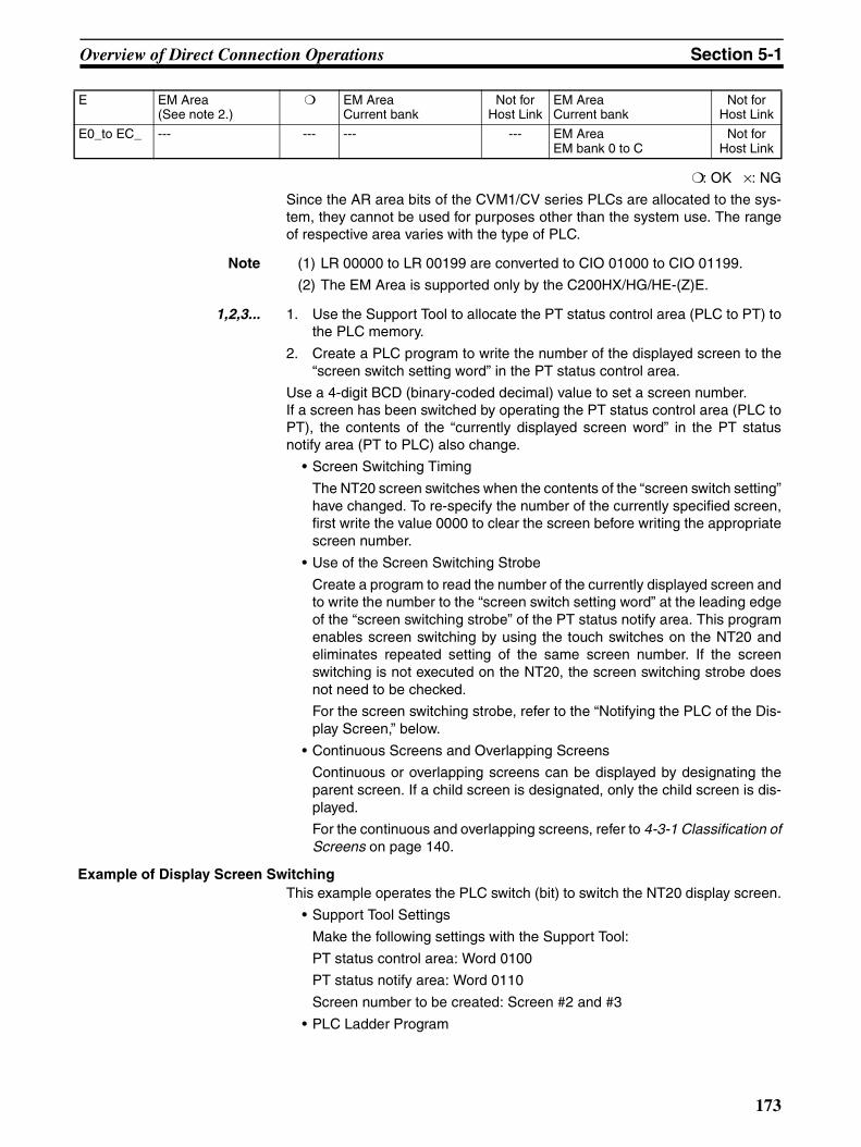
Overview of Direct Connection Operations Section 5-1
: OK ×: NG
Since the AR area bits of the CVM1/CV series PLCs are allocated to the sys-tem, they cannot be used for purposes other than the system use. The rangeof respective area varies with the type of PLC.
Note (1) LR 00000 to LR 00199 are converted to CIO 01000 to CIO 01199.
(2) The EM Area is supported only by the C200HX/HG/HE-(Z)E.
1,2,3... 1. Use the Support Tool to allocate the PT status control area (PLC to PT) tothe PLC memory.
2. Create a PLC program to write the number of the displayed screen to the“screen switch setting word” in the PT status control area.
Use a 4-digit BCD (binary-coded decimal) value to set a screen number.If a screen has been switched by operating the PT status control area (PLC toPT), the contents of the “currently displayed screen word” in the PT statusnotify area (PT to PLC) also change.
• Screen Switching Timing
The NT20 screen switches when the contents of the “screen switch setting”have changed. To re-specify the number of the currently specified screen,first write the value 0000 to clear the screen before writing the appropriatescreen number.
• Use of the Screen Switching Strobe
Create a program to read the number of the currently displayed screen andto write the number to the “screen switch setting word” at the leading edgeof the “screen switching strobe” of the PT status notify area. This programenables screen switching by using the touch switches on the NT20 andeliminates repeated setting of the same screen number. If the screenswitching is not executed on the NT20, the screen switching strobe doesnot need to be checked.
For the screen switching strobe, refer to the “Notifying the PLC of the Dis-play Screen,” below.
• Continuous Screens and Overlapping Screens
Continuous or overlapping screens can be displayed by designating theparent screen. If a child screen is designated, only the child screen is dis-played.
For the continuous and overlapping screens, refer to 4-3-1 Classification ofScreens on page 140.
Example of Display Screen SwitchingThis example operates the PLC switch (bit) to switch the NT20 display screen.
• Support Tool Settings
Make the following settings with the Support Tool:
PT status control area: Word 0100
PT status notify area: Word 0110
Screen number to be created: Screen #2 and #3
• PLC Ladder Program
E EM Area (See note 2.)
EM AreaCurrent bank
Not for Host Link
EM AreaCurrent bank
Not for Host Link
E0_to EC_ --- --- --- --- EM AreaEM bank 0 to C
Not for Host Link
173

Overview of Direct Connection Operations Section 5-1
Create a PLC ladder program as follows:
• Program Operation
1,2,3... 1. Screen #2 is displayed on the NT20 when bit 00002 turns ON.
2. Screen #3 is displayed on the NT20 when bit 00003 turns ON.
3. When the screen switch strobe flag turns ON, the number of the currentlydisplayed screen is read and written to the currently displayed screen wordin the PT status notify area. In this case, the NT20 will not write the samescreen twice.
5-1-5 Notifying the PLC of the Display Screen(to Display the Number of Currently Displayed Screen)
The following describes the processing to display the number of currently dis-played screen of the NT20.
This processing reads the data from the PLC status notify area.
To indicate that the screen has switched, use the screen switch strobe flag.
To display the number of the currently displayed screen, use the currently dis-played screen word.
When the screen has switched, the NT20 notifies the PLC of the following inPT status notify area (PT to PLC) allocated in the PLC.
Screen switch notification: Screen switch strobe flag of the PT status word
New screen number: Currently displayed screen word
By reading the currently displayed screen word when the screen switch strobeflag has turned ON, the number of the currently displayed screen on the NT20is displayed.
@MOV(21)#0002
100
00002
00003
11212
@MOV(21)#0003
100
@MOV(21)110100
(1)
Screen number
Screen switch setting word
(2)
Screen number
Screen switch setting word
(3)
Screen number
Screen switch setting wordScreen switch strobe flag
NT20 PLC
PT status notify area
Currently displayed screen Screen number
Upgraded memory table entry
PT status Screen switch strobe flag
Currently displayed
screen
174
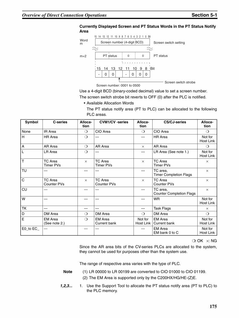
Overview of Direct Connection Operations Section 5-1
Currently Displayed Screen and PT Status Words in the PT Status Notify Area
Use a 4-digit BCD (binary-coded decimal) value to set a screen number.
The screen switch strobe bit reverts to OFF (0) after the PLC is notified.
• Available Allocation Words
The PT status notify area (PT to PLC) can be allocated to the followingPLC areas.
: OK ×: NG
Since the AR area bits of the CV-series PLCs are allocated to the system,they cannot be used for purposes other than the system use.
The range of respective area varies with the type of PLC.
Note (1) LR 00000 to LR 00199 are converted to CIO 01000 to CIO 01199.
(2) The EM Area is supported only by the C200HX/HG/HE-(Z)E.
1,2,3... 1. Use the Support Tool to allocate the PT status notify area (PT to PLC) tothe PLC memory.
15 14 13 12 11 10 9 8 7 6 5 4 3 2 1 0 Bit
- 0 0 - 0 0 0
Wordm
15 14 13 12 11 10 9 8 Bit
Screen number (4-digit BCD)
PT status 0 0 PT status
Screen number: 0001 to 0500
m+2
Screen switch strobe
Screen switch setting
Symbol C-series Alloca-tion
CVM1/CV -series Alloca-tion
CS/CJ-series Alloca-tion
None IR Area CIO Area CIO Area
H HR Area --- --- HR Area Not for Host Link
A AR Area AR Area × AR Area
L LR Area --- --- LR Area (See note 1.) Not for Host Link
T TC AreaTimer PVs
× TC AreaTimer PVs
× TC AreaTimer PVs
×
TU --- --- --- --- TC area,Timer Completion Flags
×
C TC AreaCounter PVs
× TC AreaCounter PVs
× TC AreaCounter PVs
×
CU --- --- --- --- TC area,Counter Completion Flags
×
W --- --- --- --- WR Not for Host Link
TK --- --- --- --- Task Flags ×D DM Area DM Area DM Area
E EM Area (See note 2.)
EM AreaCurrent bank
Not for Host Link
EM AreaCurrent bank
Not for Host Link
E0_to EC_ --- --- --- --- EM AreaEM bank 0 to C
Not for Host Link
175
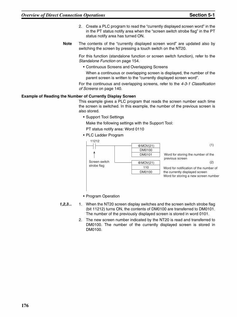
Overview of Direct Connection Operations Section 5-1
2. Create a PLC program to read the “currently displayed screen word” in thein the PT status notify area when the “screen switch strobe flag” in the PTstatus notify area has turned ON.
Note The contents of the “currently displayed screen word” are updated also byswitching the screen by pressing a touch switch on the NT20.
For this function (standalone function or screen switch function), refer to theStandalone Function on page 154.
• Continuous Screens and Overlapping Screens
When a continuous or overlapping screen is displayed, the number of theparent screen is written to the “currently displayed screen word”.
For the continuous and overlapping screens, refer to the 4-3-1 Classificationof Screens on page 140.
Example of Reading the Number of Currently Display ScreenThis example gives a PLC program that reads the screen number each timethe screen is switched. In this example, the number of the previous screen isalso stored.
• Support Tool Settings
Make the following settings with the Support Tool:
PT status notify area: Word 0110
• PLC Ladder Program
• Program Operation
1,2,3... 1. When the NT20 screen display switches and the screen switch strobe flag(bit 11212) turns ON, the contents of DM0100 are transferred to DM0101.The number of the previously displayed screen is stored in word 0101.
2. The new screen number indicated by the NT20 is read and transferred toDM0100. The number of the currently displayed screen is stored inDM0100.
@MOV(21)DM0100DM0101
11212
@MOV(21)110
DM0100
(1)
(2)
Word for storing the number of the previous screen
Word for notification of the number of the currently displayed screen Word for storing a new screen number
Screen switch strobe flag
176
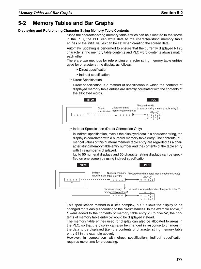
Memory Tables and Bar Graphs Section 5-2
5-2 Memory Tables and Bar GraphsDisplaying and Referencing Character String Memory Table Contents
Since the character-string memory table entries can be allocated to the wordsin the PLC, the PLC can write data to the character-string memory tableentries or the initial values can be set when creating the screen data.
Automatic updating is performed to ensure that the currently displayed NT20character string memory table contents and PLC word contents always matcheach other.There are two methods for referencing character string memory table entriesused for character string display, as follows:
• Direct specification
• Indirect specification
• Direct Specification
Direct specification is a method of specification in which the contents ofdisplayed memory table entries are directly correlated with the contents ofthe allocated words.
• Indirect Specification (Direct Connection Only)
In indirect specification, even if the displayed data is a character string, thedisplay is correlated with a numeral memory table entry. The contents (nu-merical value) of this numeral memory table entry are regarded as a char-acter string memory table entry number and the contents of the table entrywith this number is displayed.Up to 50 numeral displays and 50 character string displays can be speci-fied on one screen by using indirect specification.
This specification method is a little complex, but it allows the display to bechanged more easily according to the circumstances. In the example above, if1 were added to the contents of memory table entry 20 to give 52, the con-tents of memory table entry 52 would be displayed instead.The memory table entries used for display can also be allocated to areas inthe PLC, so that the display can also be changed in response to changes inthe data to be displayed (i.e., the contents of character string memory tableentry 51 in the example above).However, in comparison with direct specification, indirect specificationrequires more time for processing.
NT20 PLC
a b c d a b c d 6 61 2
6 63 4
DM0100
Direct specification
Character string memory table entry 51
Allocated words (character string memory table entry 51)
NT20 PLC
a b c d 0 0 5 1
a b c d
0 50 1
6 61 2
6 63 4
DM0100
Allocated word (numeral memory table entry 20)DM0000
Allocated words (character string table entry 51)
Indirect specification
Numeral memory table entry 20
Character string memory table entry 51
177
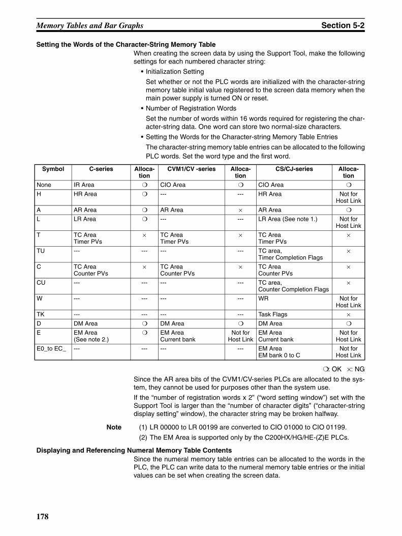
Memory Tables and Bar Graphs Section 5-2
Setting the Words of the Character-String Memory TableWhen creating the screen data by using the Support Tool, make the followingsettings for each numbered character string:
• Initialization Setting
Set whether or not the PLC words are initialized with the character-stringmemory table initial value registered to the screen data memory when themain power supply is turned ON or reset.
• Number of Registration Words
Set the number of words within 16 words required for registering the char-acter-string data. One word can store two normal-size characters.
• Setting the Words for the Character-string Memory Table Entries
The character-string memory table entries can be allocated to the followingPLC words. Set the word type and the first word.
: OK ×: NG
Since the AR area bits of the CVM1/CV-series PLCs are allocated to the sys-tem, they cannot be used for purposes other than the system use.
If the “number of registration words x 2” (“word setting window”) set with theSupport Tool is larger than the “number of character digits” (“character-stringdisplay setting” window), the character string may be broken halfway.
Note (1) LR 00000 to LR 00199 are converted to CIO 01000 to CIO 01199.
(2) The EM Area is supported only by the C200HX/HG/HE-(Z)E PLCs.
Displaying and Referencing Numeral Memory Table ContentsSince the numeral memory table entries can be allocated to the words in thePLC, the PLC can write data to the numeral memory table entries or the initialvalues can be set when creating the screen data.
Symbol C-series Alloca-tion
CVM1/CV -series Alloca-tion
CS/CJ-series Alloca-tion
None IR Area CIO Area CIO Area
H HR Area --- --- HR Area Not for Host Link
A AR Area AR Area × AR Area
L LR Area --- --- LR Area (See note 1.) Not for Host Link
T TC AreaTimer PVs
× TC AreaTimer PVs
× TC AreaTimer PVs
×
TU --- --- --- --- TC area,Timer Completion Flags
×
C TC AreaCounter PVs
× TC AreaCounter PVs
× TC AreaCounter PVs
×
CU --- --- --- --- TC area,Counter Completion Flags
×
W --- --- --- --- WR Not for Host Link
TK --- --- --- --- Task Flags ×D DM Area DM Area DM Area
E EM Area (See note 2.)
EM AreaCurrent bank
Not for Host Link
EM AreaCurrent bank
Not for Host Link
E0_to EC_ --- --- --- --- EM AreaEM bank 0 to C
Not for Host Link
178

Memory Tables and Bar Graphs Section 5-2
Also, by relating the numeral memory table entries with the bar graphs, thebar graphs corresponding to the data of the numeral memory table entriescan be displayed.
During the operation, the display contents are automatically updated so thatthe contents of the numeral memory table entry being displayed are the sameas that of the PLC word.
There are two methods for referencing numeral memory table entries used fornumeral displays, as follows:
• Direct specification
• Indirect specification
Note The only method available for numeral memory table entries used for graphsand numeral settings is direct specification.
• Direct Specification
Direct specification is a method of specification in which the contents ofdisplayed memory table entries are directly correlated with the contents ofthe allocated words.
• Indirect Specification
With indirect specification, the contents (numerical value) of the specifiednumeral memory table entry are regarded as a memory table entry numberand the contents of the table entry with this number is displayed.Up to 50 numeral displays and 50 character string displays can be speci-fied on one screen by using indirect specification.
This specification method is a little complex, but it allows the display to bechanged more easily according to the circumstances. In the exampleabove, if one were added to the contents of memory table entry 18 to give63, the contents of memory table entry 63 would be displayed instead.The memory table entries used for display can also be allocated to areasin the PLC, so that the display can also be changed in response to changesin the data to be displayed (i.e., the contents of character string memorytable entry 62 in the example above). However, in comparison with directspecification, indirect specification requires more time for processing.
Setting the Words of the Numeral Memory TableWhen creating the screen data by using the Support Tool, make the followingsettings for each numbered numeral:
NT20 PLC
0 0 6 2
Character string memory table entry 18
0 0 6 2 0 60 2
Allocated word(character string memory table entry 18)Direct
specification DM0100
NT20 PLC
7 7 7 7 0 0 6 2
7 7 7 7
0 60 2
7 77 7DM0200
DM0100
Allocated word (character string table entry 62)
Indirect specification
Character string memory table entry 62
Numeral memory table entry 18
Allocated word (numeral memory table entry 18)
179

Memory Tables and Bar Graphs Section 5-2
• Initialization Setting
Set whether or not the PLC words are initialized with the numeral memorytable initial value registered to the screen data memory when the mainpower supply is turned ON or reset.
• Number of Registration Words
Set the number of words within 2 words required for registering the numer-al data. One word can store up to 4 digits. Two words can store up to 8 dig-its.
• Setting the Words for the Numeral Memory Table
The numeral memory table entries can be allocated to the following PLCwords. Set the word type and the first word.
: OK : 1 word only ×: NG
Since the AR area bits of the CVM1/CV series PLCs are allocated to the sys-tem, they cannot be used for purposes other than the system use.
Note (1) LR 00000 to LR 00199 are converted to CIO 01000 to CIO 01199.
(2) The EM Area is supported only by C200HX/HG/HE-(Z)E PLCs.
5-2-1 Displaying the Contents of Allocated Words of Memory Table Entries
The relationship between the contents of the allocated words of numeral andcharacter string memory table entries and the display is described below.
• Contents of the Numeral Memory Table
Numerals are stored in the allocated words as shown below.
Symbol C-series Alloca-tion
CVM1/CV -series Alloca-tion
CS/CJ-series Alloca-tion
None IR Area CIO Area CIO Area
H HR Area --- --- HR Area Not for Host Link
A AR Area AR Area × AR Area
L LR Area --- --- LR Area (See note 1.) Not for Host Link
T TC AreaTimer PVs
TC AreaTimer PVs
TC AreaTimer PVs
TU --- --- --- --- TC area,Timer Completion Flags
×
C TC AreaCounter PVs
TC AreaCounter PVs
Not for Host Link
TC AreaCounter PVs
CU --- --- --- --- TC area,Counter Completion Flags
×
W --- --- --- --- WR Not for Host Link
TK --- --- --- --- Task Flags ×D DM Area DM Area DM Area
E EM Area (See note 2.)
EM AreaCurrent bank
Not for Host Link
EM AreaCurrent bank
Not for Host Link
E0_to EC_ --- --- --- --- EM AreaEM bank 0 to C
Not for Host Link
180
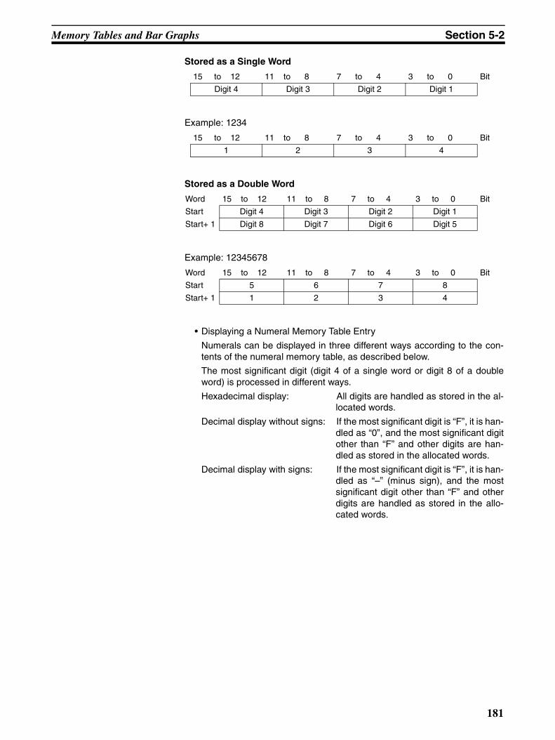
Memory Tables and Bar Graphs Section 5-2
Stored as a Single Word
Example: 1234
Stored as a Double Word
Example: 12345678
• Displaying a Numeral Memory Table Entry
Numerals can be displayed in three different ways according to the con-tents of the numeral memory table, as described below.
The most significant digit (digit 4 of a single word or digit 8 of a doubleword) is processed in different ways.
Hexadecimal display: All digits are handled as stored in the al-located words.
Decimal display without signs: If the most significant digit is “F”, it is han-dled as “0”, and the most significant digitother than “F” and other digits are han-dled as stored in the allocated words.
Decimal display with signs: If the most significant digit is “F”, it is han-dled as “–” (minus sign), and the mostsignificant digit other than “F” and otherdigits are handled as stored in the allo-cated words.
15 to 12 11 to 8 7 to 4 3 to 0 Bit
Digit 4 Digit 3 Digit 2 Digit 1
15 to 12 11 to 8 7 to 4 3 to 0 Bit
1 2 3 4
Word 15 to 12 11 to 8 7 to 4 3 to 0 Bit
Start Digit 4 Digit 3 Digit 2 Digit 1
Start+ 1 Digit 8 Digit 7 Digit 6 Digit 5
Word 15 to 12 11 to 8 7 to 4 3 to 0 Bit
Start 5 6 7 8
Start+ 1 1 2 3 4
181

Memory Tables and Bar Graphs Section 5-2
Numeral Memory Table Display Examples
• When the Data Is Numeral Data (0 to 9)
• When the Data Contains Characters (A to F)
If the hexadecimal data (A to F) are stored when the decimal display has beenset, the alphabets are displayed.
If the number of display digits has been set to be smaller than the maximumnumber of digits of the registration words (4 digits for 1 word; 8 digits for 2
words), the contents of the allocated words are not displayed and “*” symbolswill be displayed at all digits.
If the most significant digit is “F” when “decimal with signs” has been set, thenumeral is handled as a negative number. The maximum number of digits ofthe negative number becomes smaller than that of the positive number by 1digit.
The actual display will vary according to the “zero suppress” setting and deci-mal fraction setting as well as the contents described above. Refer to the “NTSupport Tool for Windows Operation Manual” (Cat. No. V061-E1-@).
• Contents of the Character-string Memory Table
A character string is stored in the allocated words beginning with the firstword in normal-size characters.
Two normal-size characters are stored in one word. One memory table en-try can store up to 16 words (32 characters).
Character-string Memory Table Display Example
To display the characters in order, allocate the characters as follows:
5-2-2 Changing Displayed Numerals or Character Strings(Changing the Contents of Allocated Words ... Direct Specification)
The following explains the actual procedure for changing the contents of allo-cated words referenced by direct specification in order to change numericalvalues and character strings displayed by the NT20.For the situation when using indirect specification, refer to 5-2-3 ChangingDisplayed Numerical Values or Character Strings (Changing the Contents ofAllocated Words ... Indirect Specification) on page 184.
Numerals and character strings can be changed also by making a copy of thememory table entries. Refer to “Copying Memory Table Entries,” below.
Start
Start + 1
Decimal without sign 123456Decimal with sign −123456Hexadecimal F0123456
3 4 5 6
F 0 1 2
Start
Start + 1
Decimal without sign 123B56Decimal with sign −123B56Hexadecimal F0123B56
3 B 5 6
F 0 1 2
Start Start + 1 Start + 15
Code 1 Code 2 Code 3 Code 4 Code31 Code32
"A"=41H, "B"=42H Start
4 7 4 8
4 1 4 2
4 3 4 4
4 5 4 6 "ABCDEFGH"
"G"=47H, "G"=48H Start + 3
"E"=45H, "F"=46H Start + 2
"C"=43H, "D"=44H Start + 1
182
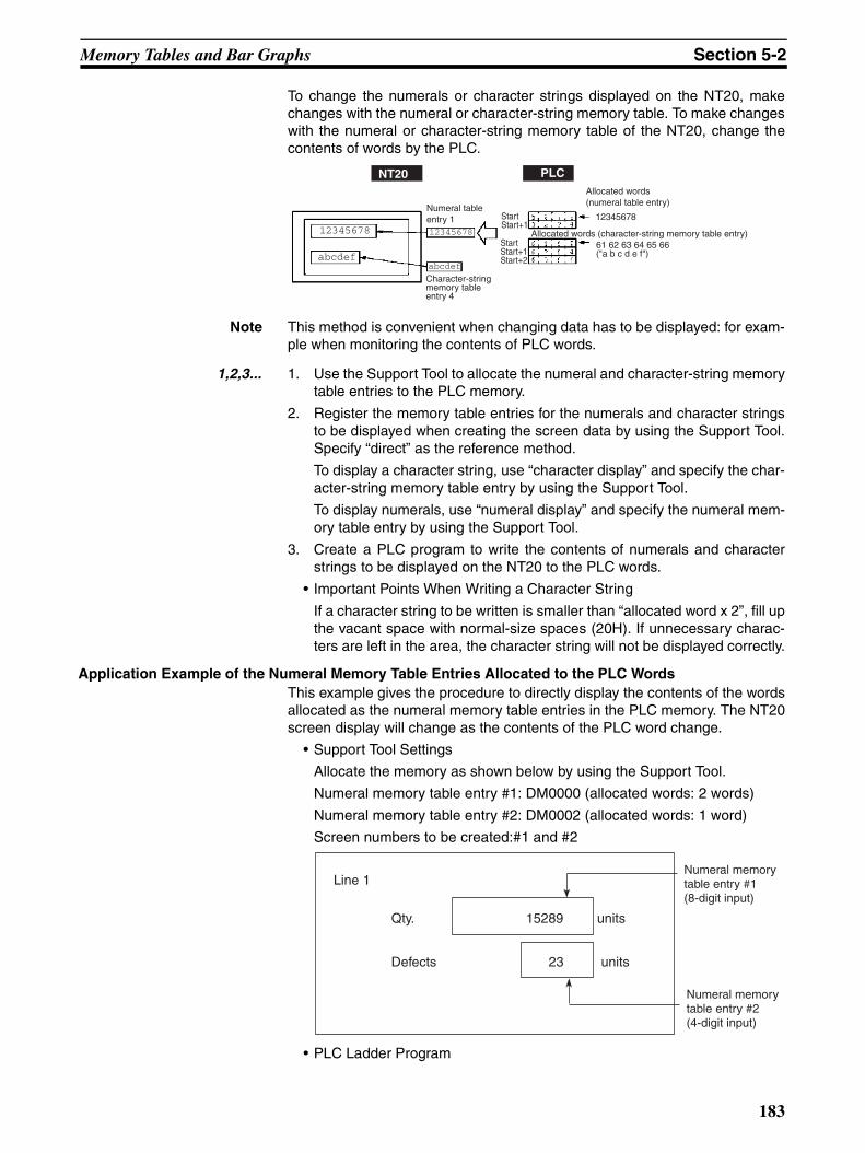
Memory Tables and Bar Graphs Section 5-2
To change the numerals or character strings displayed on the NT20, makechanges with the numeral or character-string memory table. To make changeswith the numeral or character-string memory table of the NT20, change thecontents of words by the PLC.
Note This method is convenient when changing data has to be displayed: for exam-ple when monitoring the contents of PLC words.
1,2,3... 1. Use the Support Tool to allocate the numeral and character-string memorytable entries to the PLC memory.
2. Register the memory table entries for the numerals and character stringsto be displayed when creating the screen data by using the Support Tool.Specify “direct” as the reference method.
To display a character string, use “character display” and specify the char-acter-string memory table entry by using the Support Tool.
To display numerals, use “numeral display” and specify the numeral mem-ory table entry by using the Support Tool.
3. Create a PLC program to write the contents of numerals and characterstrings to be displayed on the NT20 to the PLC words.
• Important Points When Writing a Character String
If a character string to be written is smaller than “allocated word x 2”, fill upthe vacant space with normal-size spaces (20H). If unnecessary charac-ters are left in the area, the character string will not be displayed correctly.
Application Example of the Numeral Memory Table Entries Allocated to the PLC WordsThis example gives the procedure to directly display the contents of the wordsallocated as the numeral memory table entries in the PLC memory. The NT20screen display will change as the contents of the PLC word change.
• Support Tool Settings
Allocate the memory as shown below by using the Support Tool.
Numeral memory table entry #1: DM0000 (allocated words: 2 words)
Numeral memory table entry #2: DM0002 (allocated words: 1 word)
Screen numbers to be created:#1 and #2
• PLC Ladder Program
Allocated words (character-string memory table entry)
NT20 PLC
Numeral table entry 1 Start
Start+1
Start Start+1Start+2
12345678
abcdefabcdef
12345678
61 62 63 64 65 66("a b c d e f")
Character-string memory table entry 4
Allocated words (numeral table entry)
12345678
Line 1
Qty. 15289 units
Defects 23 units
Numeral memory table entry #1 (8-digit input)
Numeral memory table entry #2 (4-digit input)
183
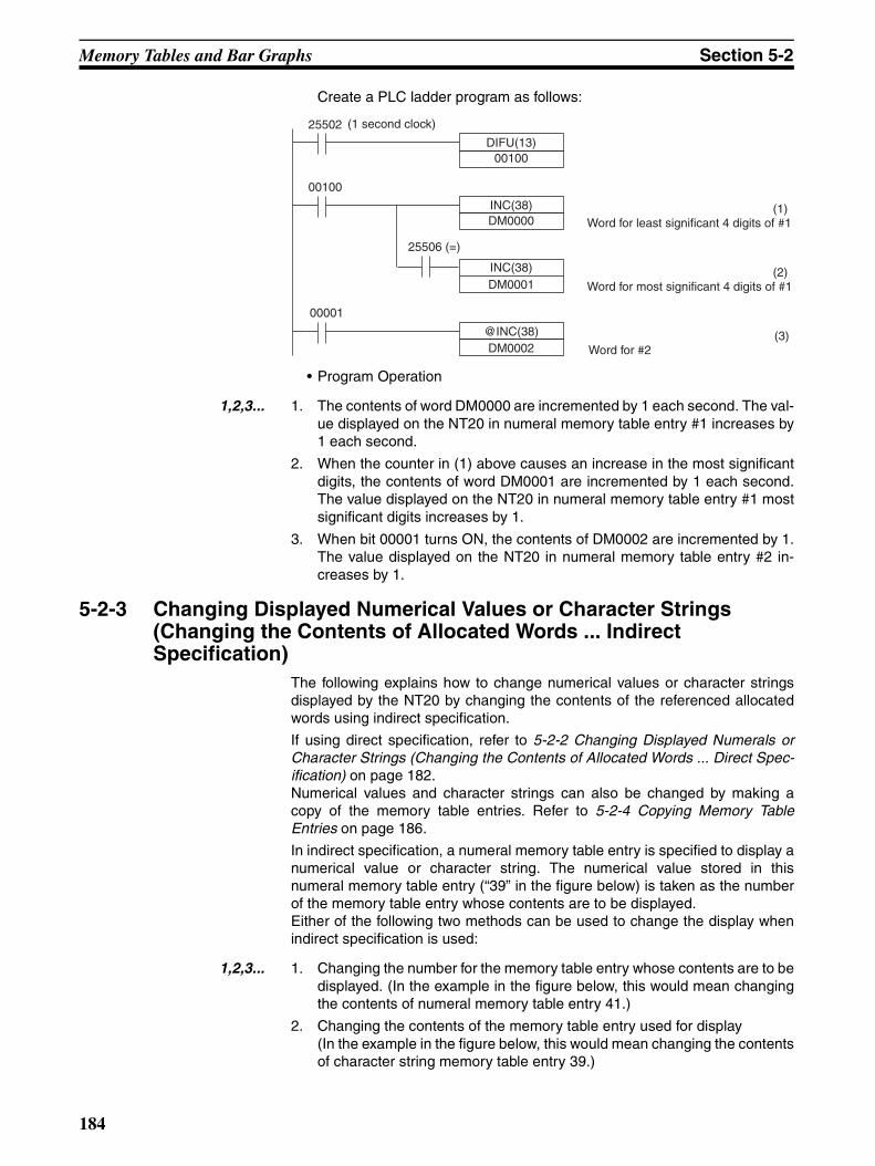
Memory Tables and Bar Graphs Section 5-2
Create a PLC ladder program as follows:
• Program Operation
1,2,3... 1. The contents of word DM0000 are incremented by 1 each second. The val-ue displayed on the NT20 in numeral memory table entry #1 increases by1 each second.
2. When the counter in (1) above causes an increase in the most significantdigits, the contents of word DM0001 are incremented by 1 each second.The value displayed on the NT20 in numeral memory table entry #1 mostsignificant digits increases by 1.
3. When bit 00001 turns ON, the contents of DM0002 are incremented by 1.The value displayed on the NT20 in numeral memory table entry #2 in-creases by 1.
5-2-3 Changing Displayed Numerical Values or Character Strings (Changing the Contents of Allocated Words ... Indirect Specification)
The following explains how to change numerical values or character stringsdisplayed by the NT20 by changing the contents of the referenced allocatedwords using indirect specification.
If using direct specification, refer to 5-2-2 Changing Displayed Numerals orCharacter Strings (Changing the Contents of Allocated Words ... Direct Spec-ification) on page 182.Numerical values and character strings can also be changed by making acopy of the memory table entries. Refer to 5-2-4 Copying Memory TableEntries on page 186.
In indirect specification, a numeral memory table entry is specified to display anumerical value or character string. The numerical value stored in thisnumeral memory table entry (“39” in the figure below) is taken as the numberof the memory table entry whose contents are to be displayed.Either of the following two methods can be used to change the display whenindirect specification is used:
1,2,3... 1. Changing the number for the memory table entry whose contents are to bedisplayed. (In the example in the figure below, this would mean changingthe contents of numeral memory table entry 41.)
2. Changing the contents of the memory table entry used for display(In the example in the figure below, this would mean changing the contentsof character string memory table entry 39.)
INC(38)DM0000
00100
INC(38)DM0001
(1)Word for least significant 4 digits of #1
@INC(38)DM0002
(2)Word for most significant 4 digits of #1
(3)Word for #2
25506 (=)
00001
DIFU(13)00100
25502 (1 second clock)
184

Memory Tables and Bar Graphs Section 5-2
Here, the method for changing the display using method 1) is explained. Fordetails on method 2), refer to the explanations on direct specification onpage 182 and 5-2-4 Copying Memory Table Entries on page 186.
Note This method is convenient when switching the display at the same location, forexample when monitoring a series of words, or when using unique codes tospecify individual character strings, etc.
1,2,3... 1. Set the PLC area for allocation of the numeral memory table entry to bereferenced in indirect specification using the Support Tool.
2. When using the Support Tool to create screen data, register on the screenthe numeral memory table entry referenced in indirect specification. Spec-ify the “indirect” option for the reference method.In the case of a character string, use the “character display” function of theSupport Tool to specify the numeral memory table entry.In the case of a numerical value, use the “numeral display” function of theSupport Tool to specify the numeral memory table entry.
3. Use the “table edit” function of the Support Tool to write the actually dis-played data to the memory table entry for display. If displaying a numericalvalue, use a numeral memory table entry and if displaying a characterstring use a character string memory table entry.
4. Create a PLC program to change the contents of the word allocated to thenumeral memory table referenced in the indirect specification.
• Precautions on Writing Memory Table Entry Numbers
When writing the number of the memory table for display to the numeralmemory table entry referenced in indirect specification, always specify it inBCD. Also, be sure to specify a number within the range of memory tableentry numbers that actually exist (0 to 127).If the contents of the numeral memory table entry for indirect specificationare specified in hexadecimal format, or the number specified is outside thevalid range for memory table entry numbers, the display is not updated.
• Precautions on Writing Character Strings
The points to note when displaying character strings are the same as thosedescribed for direct specification. Refer to Important points when writing acharacter string to page 149.
Example Use of Indirect SpecificationThis example shows a case where the displayed character string is changedby incrementing the contents of the allocated word of the numeral memorytable entry referenced in indirect specification.
• Settings with the Support Tool
Make the following settings with the Support Tool.
NT20 PLC
AaBb 0039
AaBb
Moji
0 30 9 0039
Indirect numeral memory table entry 41
Character string memory table entry 39
Character string memory table entry 40
Allocated word (numeral memory table entry 41)
185
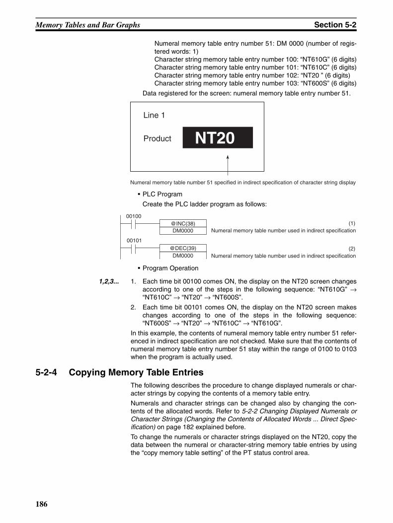
Memory Tables and Bar Graphs Section 5-2
Numeral memory table entry number 51: DM 0000 (number of regis-tered words: 1)Character string memory table entry number 100: “NT610G” (6 digits)Character string memory table entry number 101: “NT610C” (6 digits)Character string memory table entry number 102: “NT20 ” (6 digits)Character string memory table entry number 103: “NT600S” (6 digits)
Data registered for the screen: numeral memory table entry number 51.
• PLC Program
Create the PLC ladder program as follows:
• Program Operation
1,2,3... 1. Each time bit 00100 comes ON, the display on the NT20 screen changesaccording to one of the steps in the following sequence: “NT610G” →“NT610C” → “NT20” → “NT600S”.
2. Each time bit 00101 comes ON, the display on the NT20 screen makeschanges according to one of the steps in the following sequence:“NT600S” → “NT20” → “NT610C” → “NT610G”.
In this example, the contents of numeral memory table entry number 51 refer-enced in indirect specification are not checked. Make sure that the contents ofnumeral memory table entry number 51 stay within the range of 0100 to 0103when the program is actually used.
5-2-4 Copying Memory Table EntriesThe following describes the procedure to change displayed numerals or char-acter strings by copying the contents of a memory table entry.
Numerals and character strings can be changed also by changing the con-tents of the allocated words. Refer to 5-2-2 Changing Displayed Numerals orCharacter Strings (Changing the Contents of Allocated Words ... Direct Spec-ification) on page 182 explained before.
To change the numerals or character strings displayed on the NT20, copy thedata between the numeral or character-string memory table entries by usingthe “copy memory table setting” of the PT status control area.
Line 1
NT20
Numeral memory table number 51 specified in indirect specification of character string display
Product
@INC(38)DM0000
00100(1)
Numeral memory table number used in indirect specification
@DEC(39)DM0000
(2)Numeral memory table number used in indirect specification
00101
186

Memory Tables and Bar Graphs Section 5-2
Write a memory table entry number to the copy memory table setting area inthe PT status control area in the PLC memory. Data will be copied betweenthe memory table entries in the NT20 and the displayed value will changeaccordingly.
Note This procedure is convenient to switch predetermined values or characterstrings according to the situation. By preparing several units of contents, vari-ous contents can be displayed by switching them to suit the situation.
Copy Memory Table Settings of the PT Status Control Area
Copy type:
0: Copy between the character-string memory table entries
1: Copy between the numeral memory table entries
Copy source and destination memory table entry numbers: 000 to 127
• Available Allocation Words
The PT status control area can be allocated to the following PLC areas:
: OK ×: NG
NT20 PLC
PT status control areaScreen switch setting
PT status control setting
Copy source number
Copy destination numberAA
A
Memory table copy source
Copy destination (for display)
Copy memory table setting
Copy type
15 14 13 12 11 10 9 8 7 6 5 4 3 2 1 0 Bit
Wordn+1
n+2
0
Copy destination memory table entry # (3-digit BCD)
Copy source memory table entry # (3-digit BCD) Copy memory table settings
Symbol C-series Alloca-tion
CVM1/CV -series Alloca-tion
CS/CJ-series Alloca-tion
None IR Area CIO Area CIO Area
H HR Area --- --- HR Area Not for Host Link
A AR Area AR Area × AR Area
L LR Area --- --- LR Area (See note 1.) Not for Host Link
T TC AreaTimer PVs
× TC AreaTimer PVs
× TC AreaTimer PVs
×
TU --- --- --- --- TC area,Timer Completion Flags
×
C TC AreaCounter PVs
× TC AreaCounter PVs
× TC AreaCounter PVs
×
CU --- --- --- --- TC area,Counter Completion Flags
×
W --- --- --- --- WR Not for Host Link
TK --- --- --- --- Task Flags ×D DM Area DM Area DM Area
E EM Area (See note 2.)
EM AreaCurrent bank
Not for Host Link
EM AreaCurrent bank
Not for Host Link
E0_to EC_ --- --- --- --- EM AreaEM bank 0 to C
Not for Host Link
187
Memory Tables and Bar Graphs Section 5-2
Since the AR area bits of the CVM1/CV series PLCs are allocated to the sys-tem, they cannot be used for purposes other than the system use.
Note (1) LR 00000 to LR 00199 are converted to CIO 01000 to CIO 01199.
(2) The EM Area is supported only by the C200HX/HG/HE-(Z)E PLCs.
1,2,3... 1. Use the Support Tool to allocate the PT status control area (PLC to PT) tothe PLC memory.
2. Register the memory table entries for the numerals and character stringsto be displayed when creating the screen data by using the Support Tool.
To display a character string, use “character display” and specify the char-acter-string memory table entry by using the Support Tool.
To display numerals, use “numeral display” and specify the numeral mem-ory table entry by using the Support Tool.
3. Set the copy source data to the memory table entry when creating thescreen data by using the Support Tool.
Use “table edit”.
4. Create a PLC program to write the copy type, copy destination memory ta-ble entry number, and copy source memory table entry number to the“copy memory table entry” setting word in the PT status control area.
• Order for Writing to the PT Status Control Area (PLC to PT)
First write the “copy destination memory table entry number”, and then,write the “copy source memory table entry number” to the PT status controlarea (PLC to PT).
The NT20 reads the area sometimes when the PLC is writing the settings.If the “copy source memory table entry number” has been written first andis changed, unexpected memory table entries may possibly be changed.
• Allocated Words That the NT20 Reads
The NT20 reads the allocated words in the PLC for the memory table en-tries which need to be displayed. Even when a copy source memory tableentry is allocated to a PLC word, if its contents are never displayed it willbe used only at initialization.
• Use of the Copy Type
Copy will not be executed when the “copy type” is other than “0” or “1”. Thememory table entry copy is executed only when the contents of the areaare changed. To repeat copying of the same copy source and same copydestination, write a value other than “0” or “1” for the copy type, and then,write a correct value again.
• Copying a Numeral Memory Table Entry
If the display method or the number of registered words include discrepan-cies, a numeral memory table entry may not be copied and displayed cor-rectly.
Application Example of Copying of a Character-String Memory Table EntryThis example gives a PLC program to switch the character string display onthe screen by using the memory table entry copy operation as the allocatedbit is turned ON and OFF.
• Support Tool Settings
Allocate the memory as shown below by using the Support Tool.
PT status control area allocation: Word 0100
188
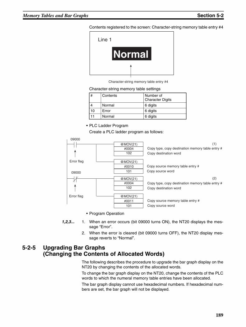
Memory Tables and Bar Graphs Section 5-2
Contents registered to the screen: Character-string memory table entry #4
Character-string memory table settings
• PLC Ladder Program
Create a PLC ladder program as follows:
• Program Operation
1,2,3... 1. When an error occurs (bit 09000 turns ON), the NT20 displays the mes-sage “Error”.
2. When the error is cleared (bit 09000 turns OFF), the NT20 display mes-sage reverts to “Normal”.
5-2-5 Upgrading Bar Graphs(Changing the Contents of Allocated Words)
The following describes the procedure to upgrade the bar graph display on theNT20 by changing the contents of the allocated words.
To change the bar graph display on the NT20, change the contents of the PLCwords to which the numeral memory table entries have been allocated.
The bar graph display cannot use hexadecimal numbers. If hexadecimal num-bers are set, the bar graph will not be displayed.
# Contents Number ofCharacter Digits
4 Normal 6 digits
10 Error 6 digits
11 Normal 6 digits
Line 1
Normal
Character-string memory table entry #4
@MOV(21)#0004
09000
@MOV(21)#0010
(1)Copy type, copy destination memory table entry #
Copy destination word
Copy source memory table entry #
Copy source word
@MOV(21)#0004
09000
@MOV(21)#0011
(2)
Copy type, copy destination memory table entry #
Copy destination word
Copy source memory table entry #
Copy source word
Error flag
Error flag
101
102
101
102
189
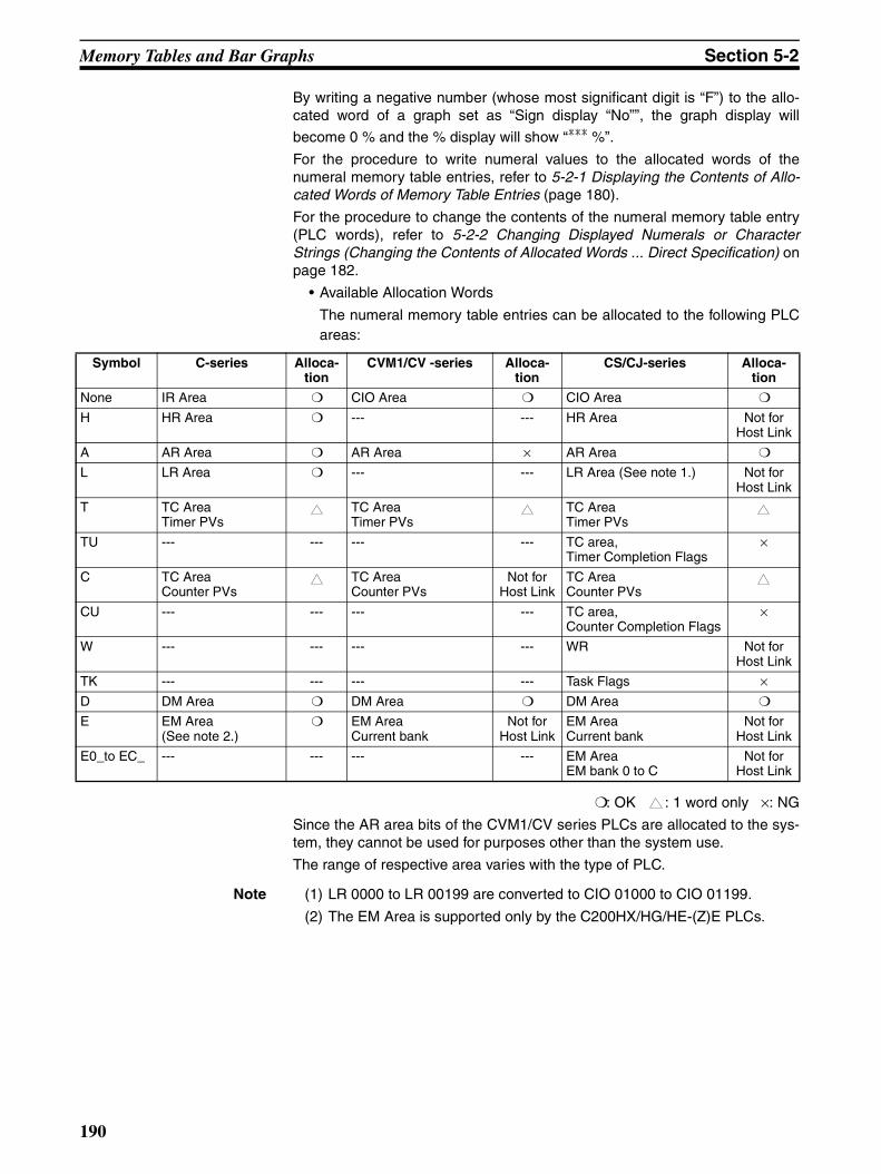
Memory Tables and Bar Graphs Section 5-2
By writing a negative number (whose most significant digit is “F”) to the allo-cated word of a graph set as “Sign display “No””, the graph display will
become 0 % and the % display will show “*** %”.
For the procedure to write numeral values to the allocated words of thenumeral memory table entries, refer to 5-2-1 Displaying the Contents of Allo-cated Words of Memory Table Entries (page 180).
For the procedure to change the contents of the numeral memory table entry(PLC words), refer to 5-2-2 Changing Displayed Numerals or CharacterStrings (Changing the Contents of Allocated Words ... Direct Specification) onpage 182.
• Available Allocation Words
The numeral memory table entries can be allocated to the following PLCareas:
: OK : 1 word only ×: NG
Since the AR area bits of the CVM1/CV series PLCs are allocated to the sys-tem, they cannot be used for purposes other than the system use.
The range of respective area varies with the type of PLC.
Note (1) LR 0000 to LR 00199 are converted to CIO 01000 to CIO 01199.
(2) The EM Area is supported only by the C200HX/HG/HE-(Z)E PLCs.
Symbol C-series Alloca-tion
CVM1/CV -series Alloca-tion
CS/CJ-series Alloca-tion
None IR Area CIO Area CIO Area
H HR Area --- --- HR Area Not for Host Link
A AR Area AR Area × AR Area
L LR Area --- --- LR Area (See note 1.) Not for Host Link
T TC AreaTimer PVs
TC AreaTimer PVs
TC AreaTimer PVs
TU --- --- --- --- TC area,Timer Completion Flags
×
C TC AreaCounter PVs
TC AreaCounter PVs
Not for Host Link
TC AreaCounter PVs
CU --- --- --- --- TC area,Counter Completion Flags
×
W --- --- --- --- WR Not for Host Link
TK --- --- --- --- Task Flags ×D DM Area DM Area DM Area
E EM Area (See note 2.)
EM AreaCurrent bank
Not for Host Link
EM AreaCurrent bank
Not for Host Link
E0_to EC_ --- --- --- --- EM AreaEM bank 0 to C
Not for Host Link
190

Lamps, Touch Switches, Numeral Setting Section 5-3
5-3 Lamps, Touch Switches, Numeral Setting
5-3-1 Allocation Bits and Display of LampsLamps are controlled by allocating them to the PLC bits. Set the area and bitnumber.
• Available Allocation Bits
The lamps can be allocated to the following PLC areas:
: OK ×: NG
Since the AR area bits of the CVM1/CV series PLCs are allocated to the sys-tem, they cannot be used for purposes other than the system use.
The range of respective area varies with the type of PLC.
Note (1) LR 00000 to LR 00199 are converted to CIO 01000 to CIO 01199.
(2) The EM Area is supported only by the C200HX/HG/HE-(Z)E PLCs.
To set the data memory (DM), specify the word number and then the bit num-ber (00 to 15).
Symbol C-series Alloca-tion
CVM1/CV -series Alloca-tion
CS/CJ-series Alloca-tion
None IR Area CIO Area CIO Area
H HR Area --- --- HR Area Not for Host Link
A AR Area AR Area × AR Area
L LR Area --- --- LR Area (See note 1.) Not for Host Link
T TC AreaTimer PVs
× TC AreaTimer PVs
× TC AreaTimer PVs
×
TU --- --- --- --- TC area,Timer Completion Flags
×
C TC AreaCounter PVs
× TC AreaCounter PVs
× TC AreaCounter PVs
×
CU --- --- --- --- TC area,Counter Completion Flags
×
W --- --- --- --- WR Not for Host Link
TK --- --- --- --- Task Flags ×D DM Area DM Area DM Area
E EM Area (See note 2.)
EM AreaCurrent bank
Not for Host Link
EM AreaCurrent bank
Not for Host Link
E0_to EC_ --- --- --- --- EM AreaEM bank 0 to C
Not for Host Link
191
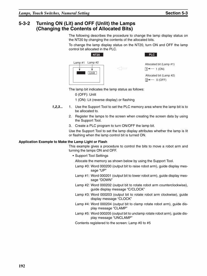
Lamps, Touch Switches, Numeral Setting Section 5-3
5-3-2 Turning ON (Lit) and OFF (Unlit) the Lamps(Changing the Contents of Allocated Bits)
The following describes the procedure to change the lamp display status onthe NT20 by changing the contents of the allocated bits.
To change the lamp display status on the NT20, turn ON and OFF the lampcontrol bit allocated in the PLC.
The lamp bit indicates the lamp status as follows:
0 (OFF): Unlit
1 (ON): Lit (reverse display) or flashing
1,2,3... 1. Use the Support Tool to set the PLC memory area where the lamp bit is tobe allocated to.
2. Register the lamps to the screen when creating the screen data by usingthe Support Tool.
3. Create a PLC program to turn ON/OFF the lamp bit.
Use the Support Tool to set the lamp display attributes whether the lamp is litor flashing when the lamp control bit is turned ON.
Application Example to Make the Lamp Light or FlashThis example gives a procedure to control the bits to move a robot arm andturning the lamps ON and OFF.
• Support Tool Settings
Allocate the memory as shown below by using the Support Tool.
Lamp #0: Word 000200 (output bit to raise robot arm), guide display mes-sage “UP”
Lamp #1: Word 000201 (output bit to lower robot arm), guide display mes-sage “DOWN”
Lamp #2: Word 000202 (output bit to rotate robot arm counterclockwise),guide display message “C/CLOCK”
Lamp #3: Word 000203 (output bit to rotate robot arm clockwise), guidedisplay message “CLOCK”
Lamp #4: Word 000204 (output bit to clamp rotate robot arm), guide dis-play message “CLAMP”
Lamp #5: Word 000205 (output bit to unclamp rotate robot arm), guide dis-play message “UNCLAMP”
Contents registered to the screen: Lamp #0 to #5
NT20 PLC
Lamp #1 Lamp #2
Unlit
Allocated bit (Lamp #1)
Allocated bit (Lamp #2)Lit
1
2 0 (OFF)
1 (ON)
192
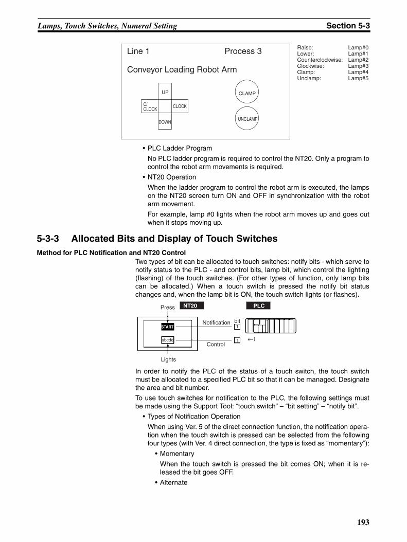
Lamps, Touch Switches, Numeral Setting Section 5-3
• PLC Ladder Program
No PLC ladder program is required to control the NT20. Only a program tocontrol the robot arm movements is required.
• NT20 Operation
When the ladder program to control the robot arm is executed, the lampson the NT20 screen turn ON and OFF in synchronization with the robotarm movement.
For example, lamp #0 lights when the robot arm moves up and goes outwhen it stops moving up.
5-3-3 Allocated Bits and Display of Touch SwitchesMethod for PLC Notification and NT20 Control
Two types of bit can be allocated to touch switches: notify bits - which serve tonotify status to the PLC - and control bits, lamp bit, which control the lighting(flashing) of the touch switches. (For other types of function, only lamp bitscan be allocated.) When a touch switch is pressed the notify bit statuschanges and, when the lamp bit is ON, the touch switch lights (or flashes).
In order to notify the PLC of the status of a touch switch, the touch switchmust be allocated to a specified PLC bit so that it can be managed. Designatethe area and bit number.
To use touch switches for notification to the PLC, the following settings mustbe made using the Support Tool: “touch switch” – “bit setting” – “notify bit”.
• Types of Notification Operation
When using Ver. 5 of the direct connection function, the notification opera-tion when the touch switch is pressed can be selected from the followingfour types (with Ver. 4 direct connection, the type is fixed as “momentary”):
• Momentary
When the touch switch is pressed the bit comes ON; when it is re-leased the bit goes OFF.
• Alternate
Line 1 Process 3
Conveyor Loading Robot Arm
Raise: Lamp#0Lower: Lamp#1Counterclockwise: Lamp#2Clockwise: Lamp#3Clamp: Lamp#4Unclamp: Lamp#5
C/CLOCK CLOCK
DOWN
UP CLAMP
UNCLAMP
START
Press
bitNotification
Lights
Control
NT20 PLC
abcde
1
1 ←1
193
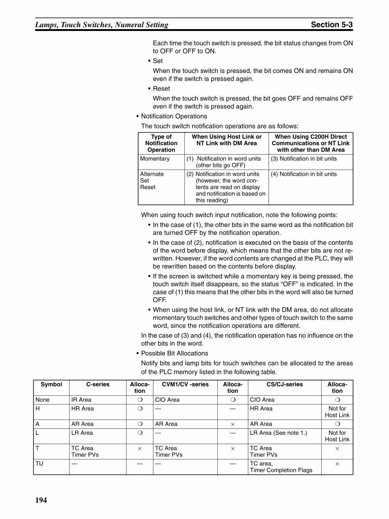
Lamps, Touch Switches, Numeral Setting Section 5-3
Each time the touch switch is pressed, the bit status changes from ONto OFF or OFF to ON.
• Set
When the touch switch is pressed, the bit comes ON and remains ONeven if the switch is pressed again.
• Reset
When the touch switch is pressed, the bit goes OFF and remains OFFeven if the switch is pressed again.
• Notification Operations
The touch switch notification operations are as follows:
When using touch switch input notification, note the following points:
• In the case of (1), the other bits in the same word as the notification bitare turned OFF by the notification operation.
• In the case of (2), notification is executed on the basis of the contentsof the word before display, which means that the other bits are not re-written. However, if the word contents are changed at the PLC, they willbe rewritten based on the contents before display.
• If the screen is switched while a momentary key is being pressed, thetouch switch itself disappears, so the status “OFF” is indicated. In thecase of (1) this means that the other bits in the word will also be turnedOFF.
• When using the host link, or NT link with the DM area, do not allocatemomentary touch switches and other types of touch switch to the sameword, since the notification operations are different.
In the case of (3) and (4), the notification operation has no influence on theother bits in the word.
• Possible Bit Allocations
Notify bits and lamp bits for touch switches can be allocated to the areasof the PLC memory listed in the following table.
Type of Notification Operation
When Using Host Link or NT Link with DM Area
When Using C200H Direct Communications or NT Link
with other than DM Area
Momentary (1) Notification in word units (other bits go OFF)
(3) Notification in bit units
Alternate Set Reset
(2) Notification in word units (however, the word con-tents are read on display and notification is based on this reading)
(4) Notification in bit units
Symbol C-series Alloca-tion
CVM1/CV -series Alloca-tion
CS/CJ-series Alloca-tion
None IR Area CIO Area CIO Area
H HR Area --- --- HR Area Not for Host Link
A AR Area AR Area × AR Area
L LR Area --- --- LR Area (See note 1.) Not for Host Link
T TC AreaTimer PVs
× TC AreaTimer PVs
× TC AreaTimer PVs
×
TU --- --- --- --- TC area,Timer Completion Flags
×
194
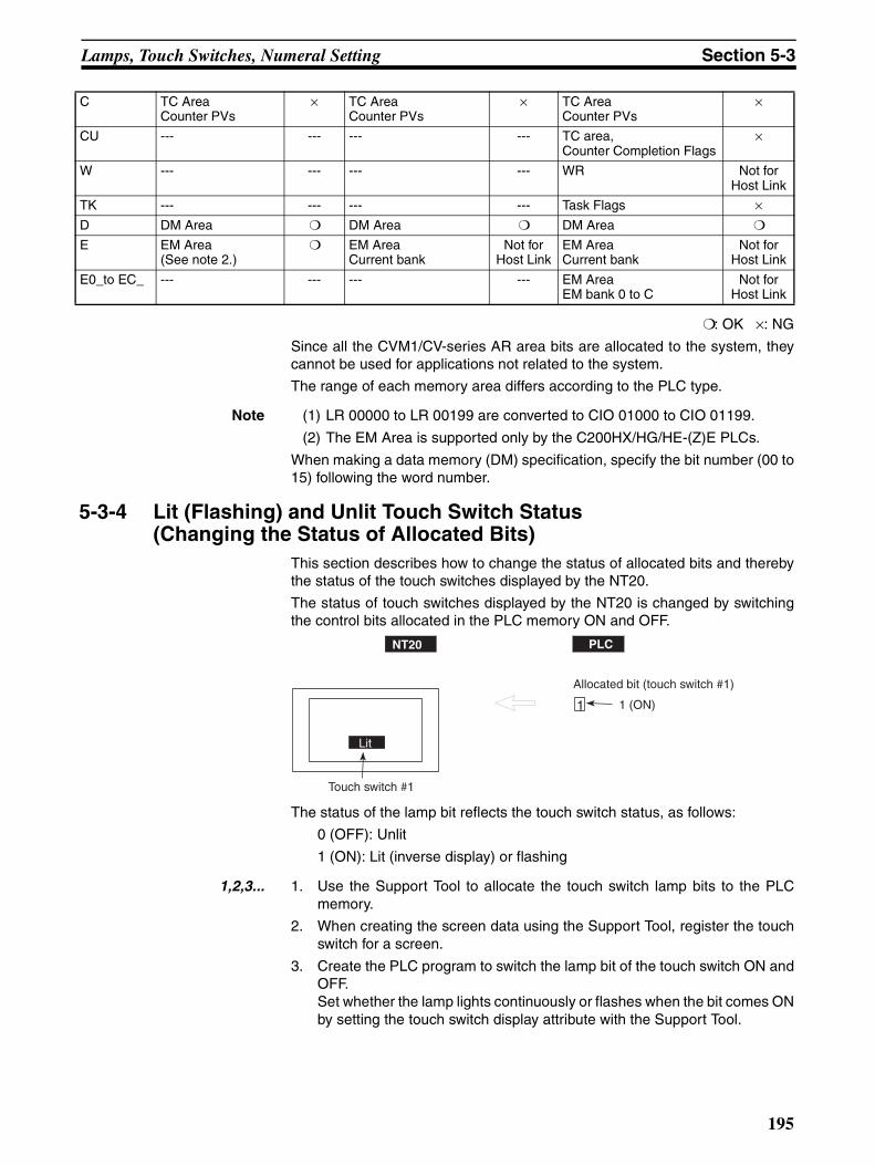
Lamps, Touch Switches, Numeral Setting Section 5-3
: OK ×: NG
Since all the CVM1/CV-series AR area bits are allocated to the system, theycannot be used for applications not related to the system.
The range of each memory area differs according to the PLC type.
Note (1) LR 00000 to LR 00199 are converted to CIO 01000 to CIO 01199.
(2) The EM Area is supported only by the C200HX/HG/HE-(Z)E PLCs.
When making a data memory (DM) specification, specify the bit number (00 to15) following the word number.
5-3-4 Lit (Flashing) and Unlit Touch Switch Status(Changing the Status of Allocated Bits)
This section describes how to change the status of allocated bits and therebythe status of the touch switches displayed by the NT20.
The status of touch switches displayed by the NT20 is changed by switchingthe control bits allocated in the PLC memory ON and OFF.
The status of the lamp bit reflects the touch switch status, as follows:
0 (OFF): Unlit
1 (ON): Lit (inverse display) or flashing
1,2,3... 1. Use the Support Tool to allocate the touch switch lamp bits to the PLCmemory.
2. When creating the screen data using the Support Tool, register the touchswitch for a screen.
3. Create the PLC program to switch the lamp bit of the touch switch ON andOFF.Set whether the lamp lights continuously or flashes when the bit comes ONby setting the touch switch display attribute with the Support Tool.
C TC AreaCounter PVs
× TC AreaCounter PVs
× TC AreaCounter PVs
×
CU --- --- --- --- TC area,Counter Completion Flags
×
W --- --- --- --- WR Not for Host Link
TK --- --- --- --- Task Flags ×D DM Area DM Area DM Area
E EM Area (See note 2.)
EM AreaCurrent bank
Not for Host Link
EM AreaCurrent bank
Not for Host Link
E0_to EC_ --- --- --- --- EM AreaEM bank 0 to C
Not for Host Link
NT20 PLC
Lit
1 1 (ON)
Allocated bit (touch switch #1)
Touch switch #1
195
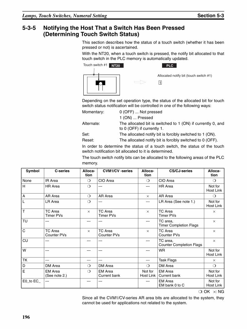
Lamps, Touch Switches, Numeral Setting Section 5-3
5-3-5 Notifying the Host That a Switch Has Been Pressed(Determining Touch Switch Status)
This section describes how the status of a touch switch (whether it has beenpressed or not) is ascertained.
With the NT20, when a touch switch is pressed, the notify bit allocated to thattouch switch in the PLC memory is automatically updated.
Depending on the set operation type, the status of the allocated bit for touchswitch status notification will be controlled in one of the following ways:
Momentary: 0 (OFF) ... Not pressed1 (ON) ... Pressed
Alternate: The allocated bit is switched to 1 (ON) if currently 0, andto 0 (OFF) if currently 1.
Set: The allocated notify bit is forcibly switched to 1 (ON).Reset: The allocated notify bit is forcibly switched to 0 (OFF).
In order to determine the status of a touch switch, the status of the touchswitch notification bit allocated to it is determined.
The touch switch notify bits can be allocated to the following areas of the PLCmemory.
: OK ×: NG
Since all the CVM1/CV-series AR area bits are allocated to the system, theycannot be used for applications not related to the system.
Touch switch #1
Allocated notify bit (touch switch #1)
NT20 PLC
1
Symbol C-series Alloca-tion
CVM1/CV -series Alloca-tion
CS/CJ-series Alloca-tion
None IR Area CIO Area CIO Area
H HR Area --- --- HR Area Not for Host Link
A AR Area AR Area × AR Area
L LR Area --- --- LR Area (See note 1.) Not for Host Link
T TC AreaTimer PVs
× TC AreaTimer PVs
× TC AreaTimer PVs
×
TU --- --- --- --- TC area,Timer Completion Flags
×
C TC AreaCounter PVs
× TC AreaCounter PVs
× TC AreaCounter PVs
×
CU --- --- --- --- TC area,Counter Completion Flags
×
W --- --- --- --- WR Not for Host Link
TK --- --- --- --- Task Flags ×D DM Area DM Area DM Area
E EM Area (See note 2.)
EM AreaCurrent bank
Not for Host Link
EM AreaCurrent bank
Not for Host Link
E0_to EC_ --- --- --- --- EM AreaEM bank 0 to C
Not for Host Link
196
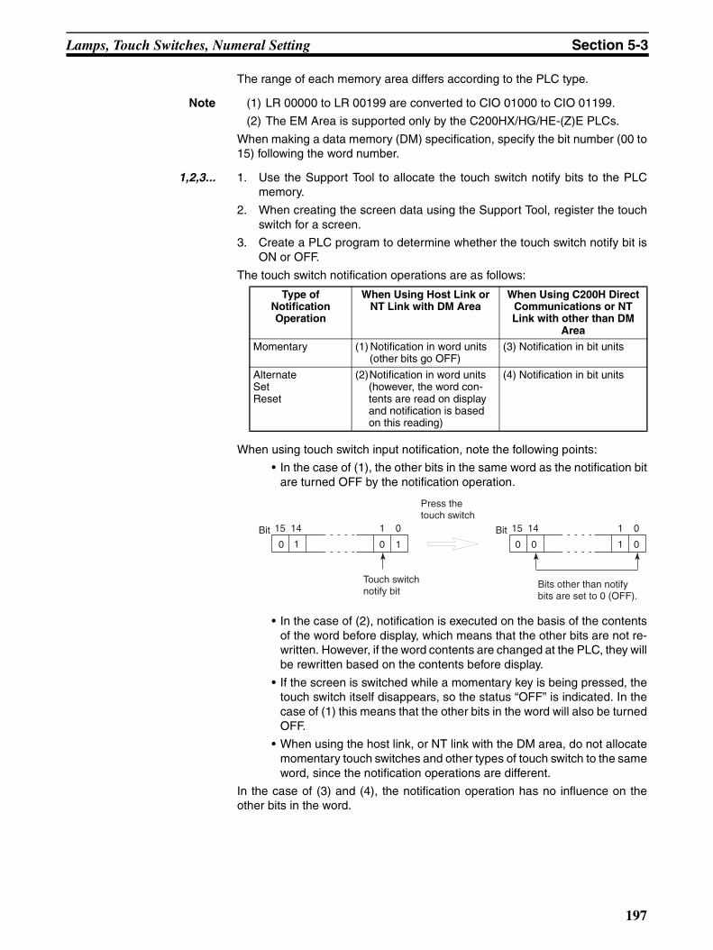
Lamps, Touch Switches, Numeral Setting Section 5-3
The range of each memory area differs according to the PLC type.
Note (1) LR 00000 to LR 00199 are converted to CIO 01000 to CIO 01199.
(2) The EM Area is supported only by the C200HX/HG/HE-(Z)E PLCs.
When making a data memory (DM) specification, specify the bit number (00 to15) following the word number.
1,2,3... 1. Use the Support Tool to allocate the touch switch notify bits to the PLCmemory.
2. When creating the screen data using the Support Tool, register the touchswitch for a screen.
3. Create a PLC program to determine whether the touch switch notify bit isON or OFF.
The touch switch notification operations are as follows:
When using touch switch input notification, note the following points:
• In the case of (1), the other bits in the same word as the notification bitare turned OFF by the notification operation.
• In the case of (2), notification is executed on the basis of the contentsof the word before display, which means that the other bits are not re-written. However, if the word contents are changed at the PLC, they willbe rewritten based on the contents before display.
• If the screen is switched while a momentary key is being pressed, thetouch switch itself disappears, so the status “OFF” is indicated. In thecase of (1) this means that the other bits in the word will also be turnedOFF.
• When using the host link, or NT link with the DM area, do not allocatemomentary touch switches and other types of touch switch to the sameword, since the notification operations are different.
In the case of (3) and (4), the notification operation has no influence on theother bits in the word.
Type of Notification Operation
When Using Host Link or NT Link with DM Area
When Using C200H Direct Communications or NT Link with other than DM
Area
Momentary (1) Notification in word units (other bits go OFF)
(3) Notification in bit units
AlternateSetReset
(2)Notification in word units (however, the word con-tents are read on display and notification is based on this reading)
(4) Notification in bit units
0 1 0 1 0 0 01
15 14 01 15 14 01Bit Bit
Bits other than notify bits are set to 0 (OFF).
Press the touch switch
Touch switch notify bit
197
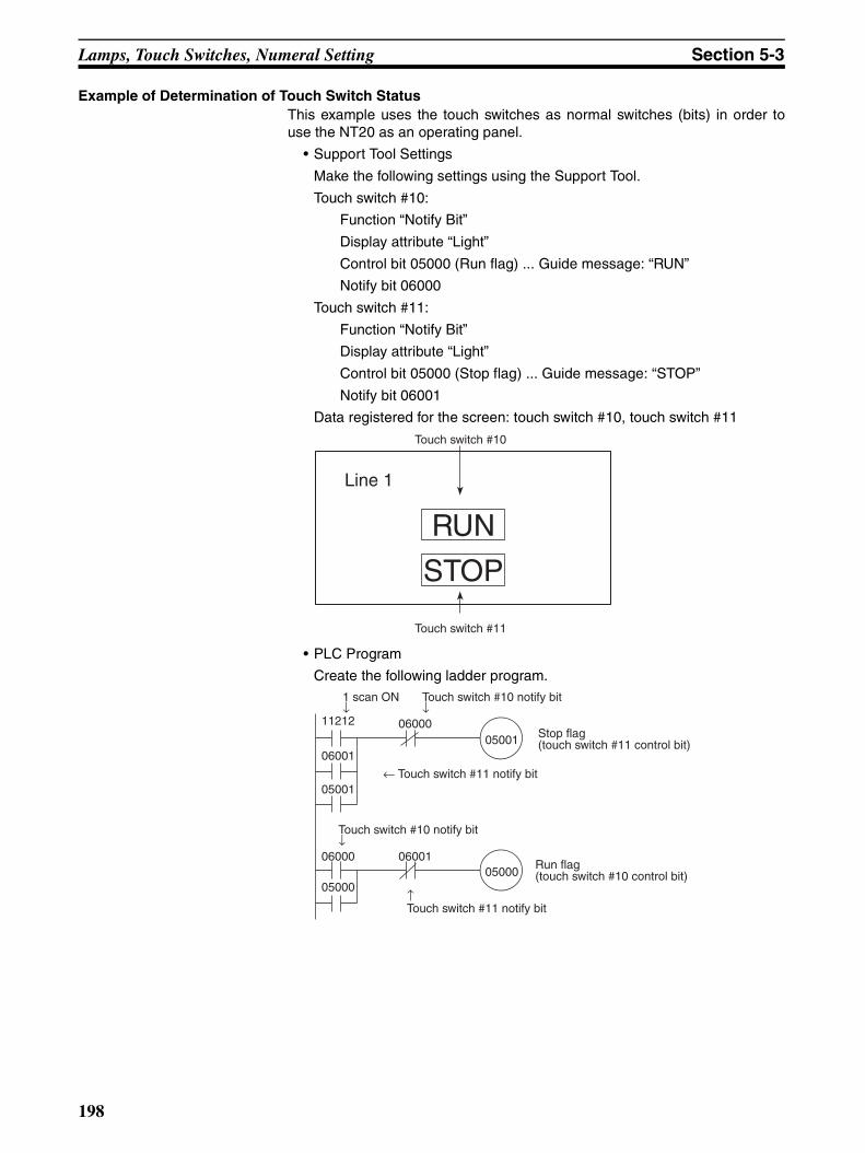
Lamps, Touch Switches, Numeral Setting Section 5-3
Example of Determination of Touch Switch StatusThis example uses the touch switches as normal switches (bits) in order touse the NT20 as an operating panel.
• Support Tool Settings
Make the following settings using the Support Tool.
Touch switch #10:
Function “Notify Bit”
Display attribute “Light”
Control bit 05000 (Run flag) ... Guide message: “RUN”
Notify bit 06000
Touch switch #11:
Function “Notify Bit”
Display attribute “Light”
Control bit 05000 (Stop flag) ... Guide message: “STOP”
Notify bit 06001
Data registered for the screen: touch switch #10, touch switch #11
• PLC Program
Create the following ladder program.
Line 1
Touch switch #11
RUN
Touch switch #10
STOP
11212
06001
05001
06000
05000
06001
0600005001
05000
1 scan ON↓
Touch switch #10 notify bit↓
Stop flag(touch switch #11 control bit)
Touch switch #10 notify bit↓
Run flag(touch switch #10 control bit)
← Touch switch #11 notify bit
↑Touch switch #11 notify bit
198
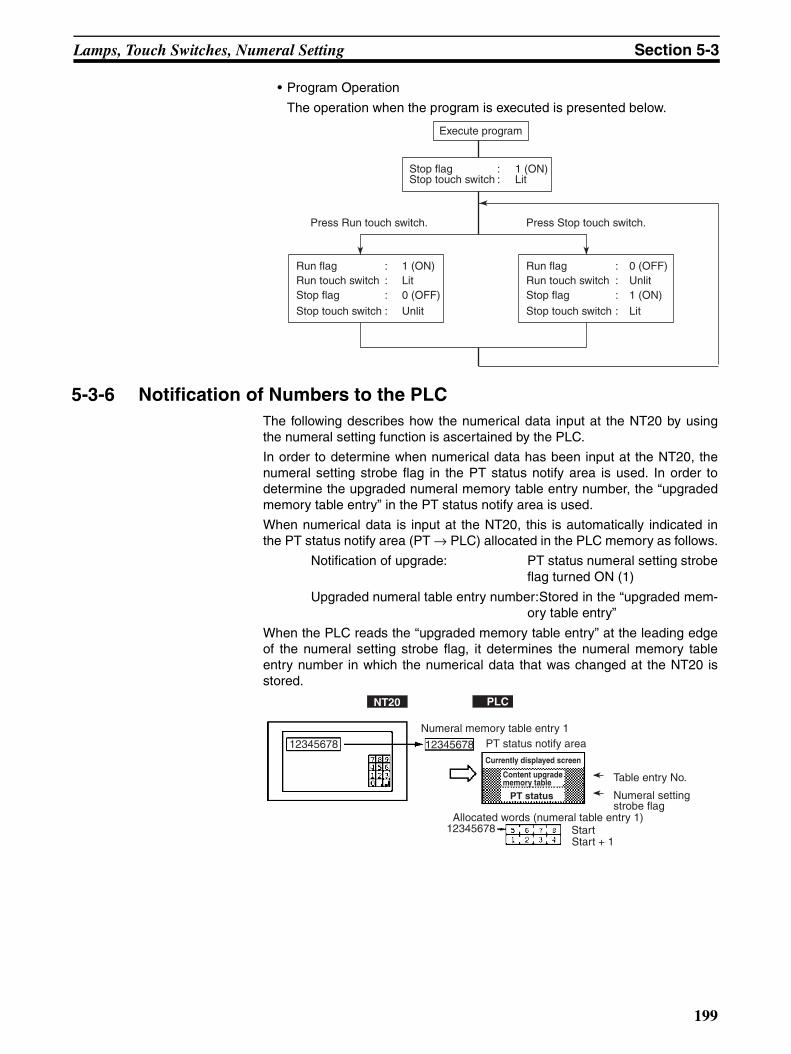
Lamps, Touch Switches, Numeral Setting Section 5-3
• Program Operation
The operation when the program is executed is presented below.
5-3-6 Notification of Numbers to the PLCThe following describes how the numerical data input at the NT20 by usingthe numeral setting function is ascertained by the PLC.
In order to determine when numerical data has been input at the NT20, thenumeral setting strobe flag in the PT status notify area is used. In order todetermine the upgraded numeral memory table entry number, the “upgradedmemory table entry” in the PT status notify area is used.
When numerical data is input at the NT20, this is automatically indicated inthe PT status notify area (PT → PLC) allocated in the PLC memory as follows.
Notification of upgrade: PT status numeral setting strobeflag turned ON (1)
Upgraded numeral table entry number:Stored in the “upgraded mem-ory table entry”
When the PLC reads the “upgraded memory table entry” at the leading edgeof the numeral setting strobe flag, it determines the numeral memory tableentry number in which the numerical data that was changed at the NT20 isstored.
Execute program
Press Run touch switch. Press Stop touch switch.
Stop flag : 1 (ON)Stop touch switch : Lit
Run flag : 1 (ON)Run touch switch : LitStop flag : 0 (OFF)
Stop touch switch : Unlit
Run flag : 0 (OFF)Run touch switch : UnlitStop flag : 1 (ON)
Stop touch switch : Lit
Numeral memory table entry 1PT status notify area
Allocated words (numeral table entry 1)StartStart + 1
NT20 PLC
12345678Currently displayed screen
PT status
Content upgrade memory table Table entry No.
Numeral setting strobe flag
12345678
12345678
199
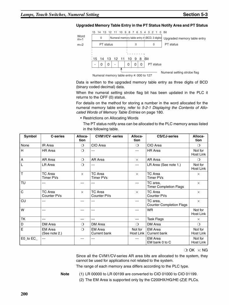
Lamps, Touch Switches, Numeral Setting Section 5-3
Upgraded Memory Table Entry in the PT Status Notify Area and PT Status
Data is written to the upgraded memory table entry as three digits of BCD(binary coded decimal) data.
When the numeral setting strobe flag bit has been updated in the PLC itreturns to the OFF (0) status.
For details on the method for storing a number in the word allocated for thenumeral memory table entry, refer to 5-2-1 Displaying the Contents of Allo-cated Words of Memory Table Entries on page 180.
• Restrictions on Allocating Words
The PT status notify area can be allocated to the PLC memory areas listedin the following table.
: OK ×: NG
Since all the CVM1/CV-series AR area bits are allocated to the system, theycannot be used for applications not related to the system.
The range of each memory area differs according to the PLC type.
Note (1) LR 00000 to LR 00199 are converted to CIO 01000 to CIO 01199.
(2) The EM Area is supported only by the C200HX/HG/HE-(Z)E PLCs.
15 14 13 12 11 10 9 8 7 6 5 4 3 2 1 0 Bit
- 0 0 - 0 0 0
Wordm+1
15 14 13 12 11 10 9 8 Bit
PT status 0 0 PT status
Numeral memory table entry #: 000 to 127
m+2
Numeral setting strobe flag
PT status
Upgraded memory table entry0 Numeral memory table entry # (BCD, 3 digits)
Symbol C-series Alloca-tion
CVM1/CV -series Alloca-tion
CS/CJ-series Alloca-tion
None IR Area CIO Area CIO Area
H HR Area --- --- HR Area Not for Host Link
A AR Area AR Area × AR Area
L LR Area --- --- LR Area (See note 1.) Not for Host Link
T TC AreaTimer PVs
× TC AreaTimer PVs
× TC AreaTimer PVs
×
TU --- --- --- --- TC area,Timer Completion Flags
×
C TC AreaCounter PVs
× TC AreaCounter PVs
× TC AreaCounter PVs
×
CU --- --- --- --- TC area,Counter Completion Flags
×
W --- --- --- --- WR Not for Host Link
TK --- --- --- --- Task Flags ×D DM Area DM Area DM Area
E EM Area (See note 2.)
EM AreaCurrent bank
Not for Host Link
EM AreaCurrent bank
Not for Host Link
E0_to EC_ --- --- --- --- EM AreaEM bank 0 to C
Not for Host Link
200
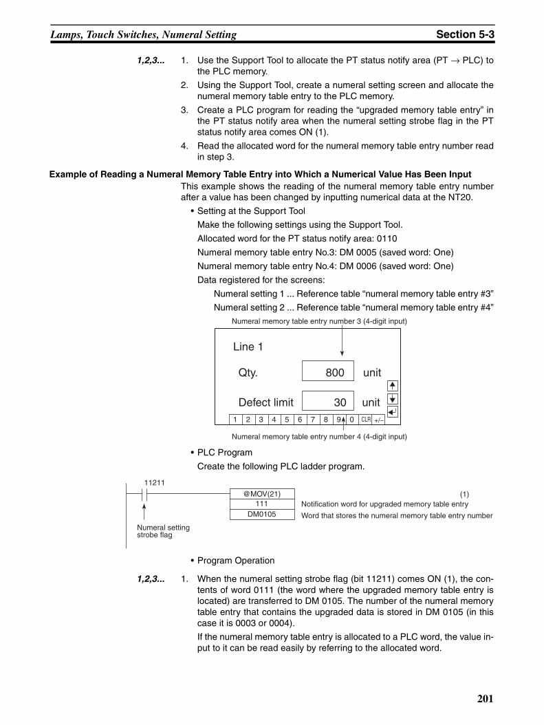
Lamps, Touch Switches, Numeral Setting Section 5-3
1,2,3... 1. Use the Support Tool to allocate the PT status notify area (PT → PLC) tothe PLC memory.
2. Using the Support Tool, create a numeral setting screen and allocate thenumeral memory table entry to the PLC memory.
3. Create a PLC program for reading the “upgraded memory table entry” inthe PT status notify area when the numeral setting strobe flag in the PTstatus notify area comes ON (1).
4. Read the allocated word for the numeral memory table entry number readin step 3.
Example of Reading a Numeral Memory Table Entry into Which a Numerical Value Has Been InputThis example shows the reading of the numeral memory table entry numberafter a value has been changed by inputting numerical data at the NT20.
• Setting at the Support Tool
Make the following settings using the Support Tool.
Allocated word for the PT status notify area: 0110
Numeral memory table entry No.3: DM 0005 (saved word: One)
Numeral memory table entry No.4: DM 0006 (saved word: One)
Data registered for the screens:
Numeral setting 1 ... Reference table “numeral memory table entry #3”
Numeral setting 2 ... Reference table “numeral memory table entry #4”
• PLC Program
Create the following PLC ladder program.
• Program Operation
1,2,3... 1. When the numeral setting strobe flag (bit 11211) comes ON (1), the con-tents of word 0111 (the word where the upgraded memory table entry islocated) are transferred to DM 0105. The number of the numeral memorytable entry that contains the upgraded data is stored in DM 0105 (in thiscase it is 0003 or 0004).
If the numeral memory table entry is allocated to a PLC word, the value in-put to it can be read easily by referring to the allocated word.
Line 1
Qty. 800 unit
Numeral memory table entry number 3 (4-digit input)
Defect limit 30 unit
Numeral memory table entry number 4 (4-digit input)
1 2 3 4 5 6 7 8 9 0 CLR +/−
@MOV(21)111
DM0105
11211
(1)Notification word for upgraded memory table entry
Word that stores the numeral memory table entry number
Numeral setting strobe flag
201

Lamps, Touch Switches, Numeral Setting Section 5-3
In this case, the contents of numeral memory table entry #3 is stored in DM0005 and the contents of numeral table entry #4 is stored in DM 0006.
202
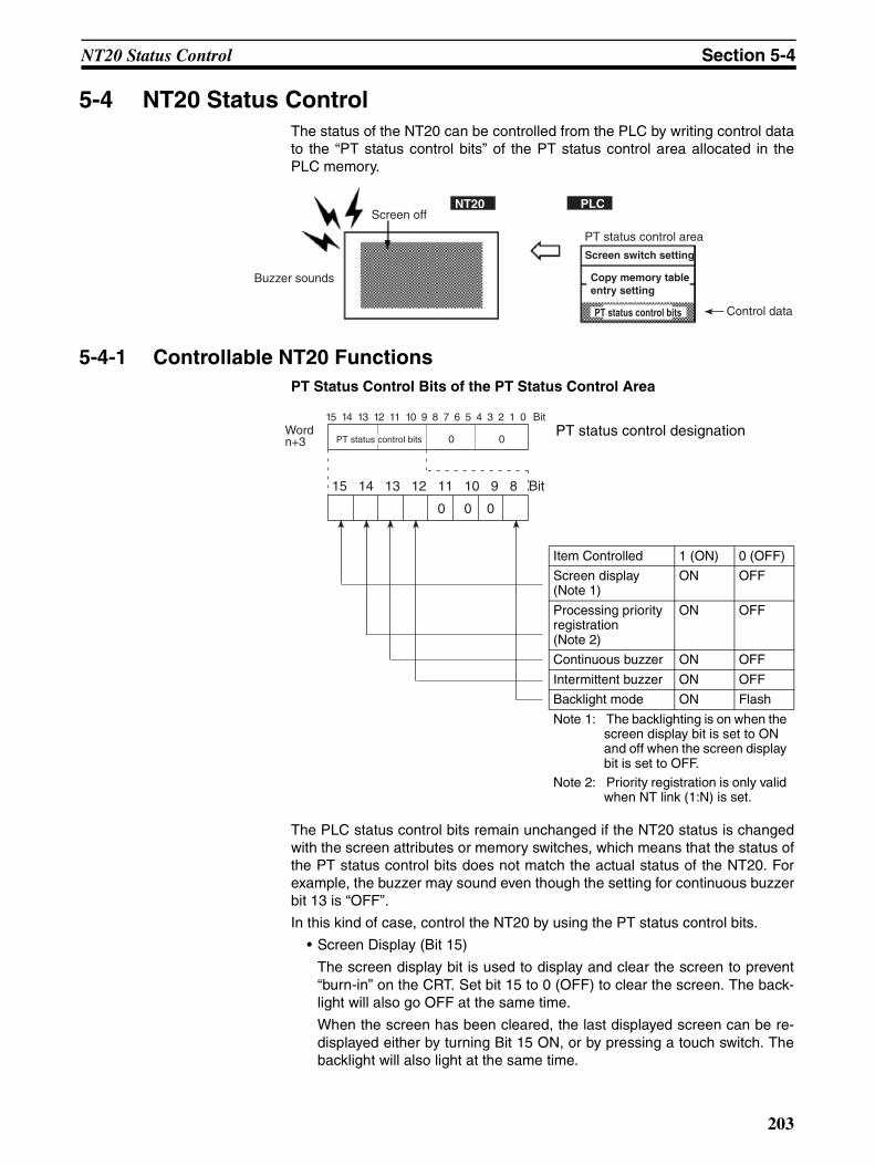
NT20 Status Control Section 5-4
5-4 NT20 Status ControlThe status of the NT20 can be controlled from the PLC by writing control datato the “PT status control bits” of the PT status control area allocated in thePLC memory.
5-4-1 Controllable NT20 FunctionsPT Status Control Bits of the PT Status Control Area
PT status control designation
The PLC status control bits remain unchanged if the NT20 status is changedwith the screen attributes or memory switches, which means that the status ofthe PT status control bits does not match the actual status of the NT20. Forexample, the buzzer may sound even though the setting for continuous buzzerbit 13 is “OFF”.
In this kind of case, control the NT20 by using the PT status control bits.
• Screen Display (Bit 15)
The screen display bit is used to display and clear the screen to prevent“burn-in” on the CRT. Set bit 15 to 0 (OFF) to clear the screen. The back-light will also go OFF at the same time.
When the screen has been cleared, the last displayed screen can be re-displayed either by turning Bit 15 ON, or by pressing a touch switch. Thebacklight will also light at the same time.
Buzzer sounds
Screen off
PT status control area
Screen switch setting
Control data
NT20 PLC
PT status control bits
Copy memory table entry setting
Item Controlled 1 (ON) 0 (OFF)
Screen display (Note 1)
ON OFF
Processing priority registration (Note 2)
ON OFF
Continuous buzzer ON OFF
Intermittent buzzer ON OFF
Backlight mode ON Flash
Note 1: The backlighting is on when the screen display bit is set to ON and off when the screen display bit is set to OFF.
Note 2: Priority registration is only valid when NT link (1:N) is set.
15 14 13 12 11 10 9 8 7 6 5 4 3 2 1 0 Bit
0 0 0
Wordn+3
15 14 13 12 11 10 9 8 Bit
PT status control bits 0 0
203
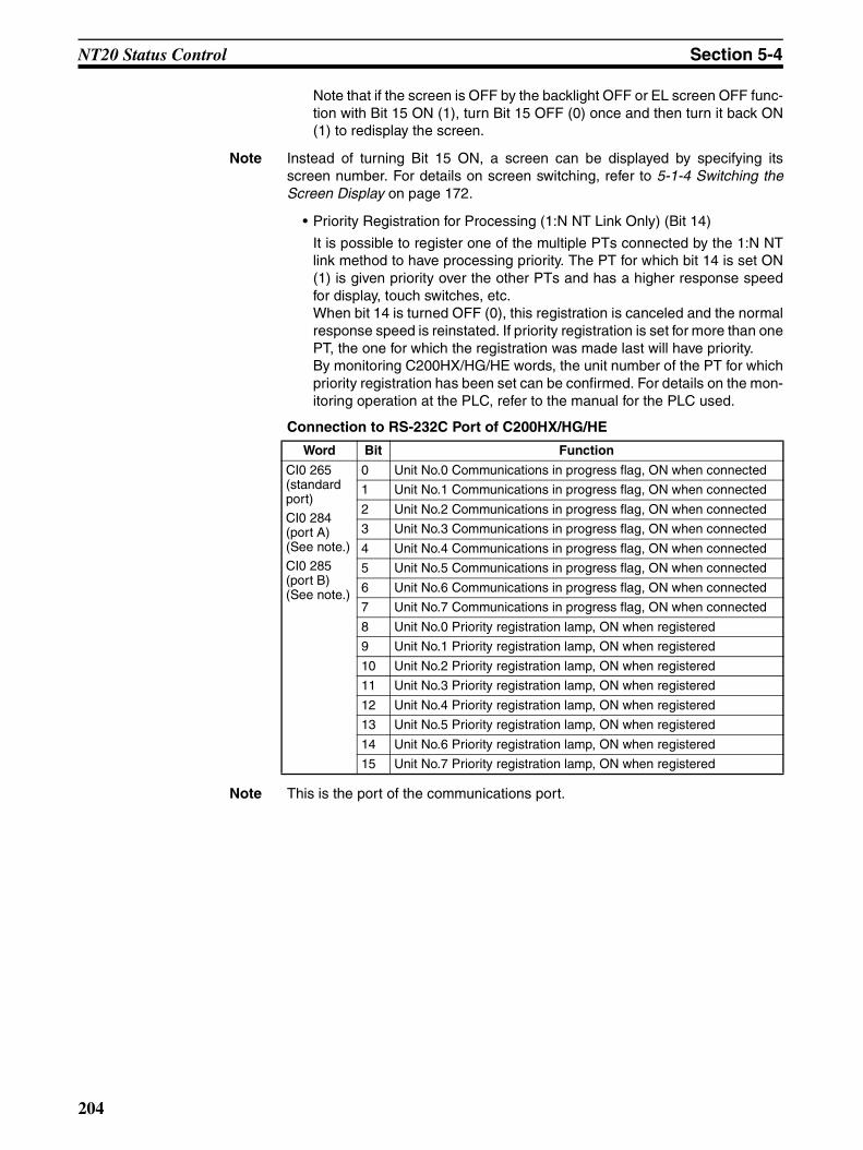
NT20 Status Control Section 5-4
Note that if the screen is OFF by the backlight OFF or EL screen OFF func-tion with Bit 15 ON (1), turn Bit 15 OFF (0) once and then turn it back ON(1) to redisplay the screen.
Note Instead of turning Bit 15 ON, a screen can be displayed by specifying itsscreen number. For details on screen switching, refer to 5-1-4 Switching theScreen Display on page 172.
• Priority Registration for Processing (1:N NT Link Only) (Bit 14)
It is possible to register one of the multiple PTs connected by the 1:N NTlink method to have processing priority. The PT for which bit 14 is set ON(1) is given priority over the other PTs and has a higher response speedfor display, touch switches, etc.When bit 14 is turned OFF (0), this registration is canceled and the normalresponse speed is reinstated. If priority registration is set for more than onePT, the one for which the registration was made last will have priority.By monitoring C200HX/HG/HE words, the unit number of the PT for whichpriority registration has been set can be confirmed. For details on the mon-itoring operation at the PLC, refer to the manual for the PLC used.
Connection to RS-232C Port of C200HX/HG/HE
Note This is the port of the communications port.
Word Bit Function
CI0 265 (standard port)
CI0 284 (port A) (See note.)
CI0 285 (port B) (See note.)
0 Unit No.0 Communications in progress flag, ON when connected
1 Unit No.1 Communications in progress flag, ON when connected
2 Unit No.2 Communications in progress flag, ON when connected
3 Unit No.3 Communications in progress flag, ON when connected
4 Unit No.4 Communications in progress flag, ON when connected
5 Unit No.5 Communications in progress flag, ON when connected
6 Unit No.6 Communications in progress flag, ON when connected
7 Unit No.7 Communications in progress flag, ON when connected
8 Unit No.0 Priority registration lamp, ON when registered
9 Unit No.1 Priority registration lamp, ON when registered
10 Unit No.2 Priority registration lamp, ON when registered
11 Unit No.3 Priority registration lamp, ON when registered
12 Unit No.4 Priority registration lamp, ON when registered
13 Unit No.5 Priority registration lamp, ON when registered
14 Unit No.6 Priority registration lamp, ON when registered
15 Unit No.7 Priority registration lamp, ON when registered
204
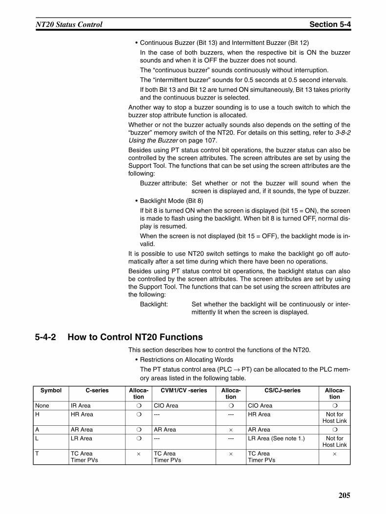
NT20 Status Control Section 5-4
• Continuous Buzzer (Bit 13) and Intermittent Buzzer (Bit 12)
In the case of both buzzers, when the respective bit is ON the buzzersounds and when it is OFF the buzzer does not sound.
The “continuous buzzer” sounds continuously without interruption.
The “intermittent buzzer” sounds for 0.5 seconds at 0.5 second intervals.
If both Bit 13 and Bit 12 are turned ON simultaneously, Bit 13 takes priorityand the continuous buzzer is selected.
Another way to stop a buzzer sounding is to use a touch switch to which thebuzzer stop attribute function is allocated.
Whether or not the buzzer actually sounds also depends on the setting of the“buzzer” memory switch of the NT20. For details on this setting, refer to 3-8-2Using the Buzzer on page 107.
Besides using PT status control bit operations, the buzzer status can also becontrolled by the screen attributes. The screen attributes are set by using theSupport Tool. The functions that can be set using the screen attributes are thefollowing:
Buzzer attribute: Set whether or not the buzzer will sound when thescreen is displayed and, if it sounds, the type of buzzer.
• Backlight Mode (Bit 8)
If bit 8 is turned ON when the screen is displayed (bit 15 = ON), the screenis made to flash using the backlight. When bit 8 is turned OFF, normal dis-play is resumed.
When the screen is not displayed (bit 15 = OFF), the backlight mode is in-valid.
It is possible to use NT20 switch settings to make the backlight go off auto-matically after a set time during which there have been no operations.
Besides using PT status control bit operations, the backlight status can alsobe controlled by the screen attributes. The screen attributes are set by usingthe Support Tool. The functions that can be set using the screen attributes arethe following:
Backlight: Set whether the backlight will be continuously or inter-mittently lit when the screen is displayed.
5-4-2 How to Control NT20 FunctionsThis section describes how to control the functions of the NT20.
• Restrictions on Allocating Words
The PT status control area (PLC → PT) can be allocated to the PLC mem-ory areas listed in the following table.
Symbol C-series Alloca-tion
CVM1/CV -series Alloca-tion
CS/CJ-series Alloca-tion
None IR Area CIO Area CIO Area
H HR Area --- --- HR Area Not for Host Link
A AR Area AR Area × AR Area
L LR Area --- --- LR Area (See note 1.) Not for Host Link
T TC AreaTimer PVs
× TC AreaTimer PVs
× TC AreaTimer PVs
×
205

NT20 Status Control Section 5-4
: OK ×: NG
Since all the CVM1/CV-series AR area bits are allocated to the system, theycannot be used for applications not related to the system.
The range of each memory area differs according to the PLC type.
Note (1) LR 0000 to LR 00199 are converted to CIO 01000 to CIO 01199.
(2) The EM Area is supported only by the C200HX/HG/HE-(Z)E PLCs.
1,2,3... 1. Use the Support Tool to set the area at the PLC used for allocation of thePT status control area (PLC → PT).
2. Write a PLC program for writing the control data into the “PT status controlbit” of the PT status control area.
• Timing for Control of the PT Status Control Bit
The PT status control bit is not read when the NT20 is started up. It is read,and control executed, only when the contents of the PT status control bitare read for the first time after the NT20 is started up.Since NT20 status control is executed when the bit corresponding to thePT status control bit changes, in order to perform the same control againthe corresponding bit must be specified again.
Example of Use of PT Status Control BitThe example below explains how operation with the PT status control bit canbe used to use the NT20 like a warning lamp.
• Setting with the Support Tool
Make the following setting with the Support Tool.
Allocated word for PT status control area: Word 0100
• PLC Program
Create the PLC ladder program as follows.
TU --- --- --- --- TC area,Timer Completion Flags
×
C TC AreaCounter PVs
× TC AreaCounter PVs
× TC AreaCounter PVs
×
CU --- --- --- --- TC area,Counter Completion Flags
×
W --- --- --- --- WR Not for Host Link
TK --- --- --- --- Task Flags ×D DM Area DM Area DM Area
E EM Area (See note 2.)
EM AreaCurrent bank
Not for Host Link
EM AreaCurrent bank
Not for Host Link
E0_to EC_ --- --- --- --- EM AreaEM bank 0 to C
Not for Host Link
206

NT20 Status Control Section 5-4
• Program Operation
1,2,3... 1. The PT status control bits are set as shown below when bit 09002 turnsOFF. This command block is not executed until bit 09003 is ON.
Screen display (bit 15) 1 (ON)
Continuous buzzer (bit 13) 1 (ON)
The NT20 continuous buzzer sounds.
2. The PT status control bits are set as shown below when bit 09003 turnsOFF.
Screen display (bit 15) 1 (ON)
Intermittent buzzer (bit 12) 1 (ON)
The NT20 intermittent buzzer sounds
3. The PT status control bits are set as shown below when both bits 09002and 09003 turn ON.
Continuous buzzer (bit 13) 0 (OFF)
Intermittent buzzer (bit 12) 0 (OFF)
The NT20 buzzer stops.
@MOV(21)#A000
09002
@MOV(21)#9000
(1)
Display screen, sound buzzer continuouslyPT status control word
(2)
Display screen, sound buzzer intermittentlyPT status control word
@ANDW(34)103
09002
(3)PT status control word"0" set for continuous and intermittent buzzer sounds onlyPT status control word
#CFFF
103
103
09003
09003
09003
103
207
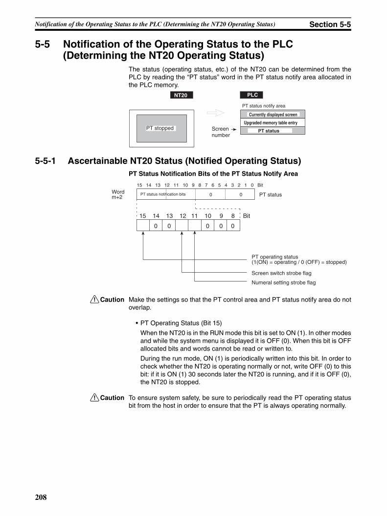
Notification of the Operating Status to the PLC (Determining the NT20 Operating Status) Section 5-5
5-5 Notification of the Operating Status to the PLC(Determining the NT20 Operating Status)
The status (operating status, etc.) of the NT20 can be determined from thePLC by reading the “PT status” word in the PT status notify area allocated inthe PLC memory.
5-5-1 Ascertainable NT20 Status (Notified Operating Status)PT Status Notification Bits of the PT Status Notify Area
!Caution Make the settings so that the PT control area and PT status notify area do notoverlap.
• PT Operating Status (Bit 15)
When the NT20 is in the RUN mode this bit is set to ON (1). In other modesand while the system menu is displayed it is OFF (0). When this bit is OFFallocated bits and words cannot be read or written to.
During the run mode, ON (1) is periodically written into this bit. In order tocheck whether the NT20 is operating normally or not, write OFF (0) to thisbit: if it is ON (1) 30 seconds later the NT20 is running, and if it is OFF (0),the NT20 is stopped.
!Caution To ensure system safety, be sure to periodically read the PT operating statusbit from the host in order to ensure that the PT is always operating normally.
NT20 PLC
PT stopped
PT status notify area
Currently displayed screen
Upgraded memory table entry
PT statusScreen number
15 14 13 12 11 10 9 8 7 6 5 4 3 2 1 0 Bit
0 0 0 0 0
Wordm+2
15 14 13 12 11 10 9 8 Bit
PT status notification bits 0 0 PT status
PT operating status(1(ON) = operating / 0 (OFF) = stopped)
Screen switch strobe flag
Numeral setting strobe flag
208

Notification of the Operating Status to the PLC (Determining the NT20 Operating Status) Section 5-5
• Screen Switch Strobe Flag (Bit 12)When the screen displayed on the NT20 is switched by a designation fromthe PLC or by the standalone function, the screen switch strobe flag comesON (1). On notification to the PLC, it returns to the OFF (0) status.
For details on how the screen switch strobe flag is used, refer to 5-1-5 No-tifying the PLC of the Display Screen (to Display the Number of CurrentlyDisplayed Screen) on page 174.
• Numeral Setting Strobe Flag (Bit 11)
When numerical data is input to a numeral memory table entry using theNT20 numeral setting function, the numeral setting strobe flag comes ON(1). On notification to the PLC, it returns to the OFF (0) status.
For details on how the numeral setting strobe flag is used, refer to 5-3-6Notification of Numbers to the PLC page 199.
5-5-2 Reading the NT20 Operating StatusThis section explains how to determine the status of the NT20, and ascertainits operating status.
To ascertain the operating status of the NT20, “PT status” is used.
The NT20 automatically notifies the PLC of information such as the operatingstatus in the PT status word of the PT status notify area (PT → PLC) allocatedin PLC memory as shown below.
Notification of operation mode: PT operating statusNotification of screen switching: Screen switch strobe flagNotification of numerical data upgrade: Numeral setting strobe flag
• Restrictions on Allocating WordsThe PT status notify area (PT → PLC) can be allocated to the PLC memoryareas listed in the following table.
: OK ×: NG
Symbol C-series Alloca-tion
CVM1/CV -series Alloca-tion
CS/CJ-series Alloca-tion
None IR Area CIO Area CIO Area
H HR Area --- --- HR Area Not for Host Link
A AR Area AR Area × AR Area
L LR Area --- --- LR Area (See note 1.) Not for Host Link
T TC AreaTimer PVs
× TC AreaTimer PVs
× TC AreaTimer PVs
×
TU --- --- --- --- TC area,Timer Completion Flags
×
C TC AreaCounter PVs
× TC AreaCounter PVs
× TC AreaCounter PVs
×
CU --- --- --- --- TC area,Counter Completion Flags
×
W --- --- --- --- WR Not for Host Link
TK --- --- --- --- Task Flags ×D DM Area DM Area DM Area
E EM Area (See note 2.)
EM AreaCurrent bank
Not for Host Link
EM AreaCurrent bank
Not for Host Link
E0_to EC_ --- --- --- --- EM AreaEM bank 0 to C
Not for Host Link
209

Notification of the Operating Status to the PLC (Determining the NT20 Operating Status) Section 5-5
Since all the CVM1/CV-series AR area bits are allocated to the system, theycannot be used for applications not related to the system.
The range of each memory area differs according to the PLC type.
Note (1) LR 00000 to LR 00199 are converted to CIO 01000 to CIO 01199.
(2) The EM Area is supported only by the C200HX/HG/HE-(Z)E PLCs.
1,2,3... 1. Use the Support Tool to allocate the PT status notify area (PT → PLC) tothe PLC memory.
2. Write a PLC program to read the “PT status” word of the PT status notifyarea and check each bit status.
• Timing of PT Status Notify Bit Notification
The contents of the PT status notify area (PT → PLC) are written to thePLC whenever the status of the NT20 changes during operation.
Example of PT Status Notify Bit ApplicationIn the example below, the status of the NT20 is checked by PT status notify bitnotification.
• Settings with the Support Tool
Make the following setting with the Support Tool.
Allocated word for PT status notify area: Word 0110
• PLC Program
Create the following PLC ladder program.
• Program Operation
1,2,3... 1. When the PT operating status (bit 11215) is OFF (0), “1” (PT stopped) isstored in DM0001.
2. When the PT operating status (bit 11215) is ON (1), “2” (PT running) isstored in DM0001.
@MOV(21)#0001
11215
@MOV(21)#0002
(1)PT stopped
Word that stores the PT status
(2)
PT running
Word that stores the PT statusDM0001
DM000111215
210
SECTION 6Using RS-232C Communications
This section describes how to carry out communications via the RS-232C interface used with the NT20-ST128, focusingon the commands.
6-1 Table of Commands . . . . . . . . . . . . . . . . . . . . . . . . . . . . . . . . . . . . . . . . . . . . 212
6-2 RS-232C Communications . . . . . . . . . . . . . . . . . . . . . . . . . . . . . . . . . . . . . . . 213
6-2-1 Communications Procedure . . . . . . . . . . . . . . . . . . . . . . . . . . . . . . . 213
6-2-2 Precautions . . . . . . . . . . . . . . . . . . . . . . . . . . . . . . . . . . . . . . . . . . . . 214
6-3 Screen Display . . . . . . . . . . . . . . . . . . . . . . . . . . . . . . . . . . . . . . . . . . . . . . . . 216
6-4 Memory Tables . . . . . . . . . . . . . . . . . . . . . . . . . . . . . . . . . . . . . . . . . . . . . . . . 218
6-5 Lamps, Touch Switches, Numeral Setting . . . . . . . . . . . . . . . . . . . . . . . . . . . 221
6-5-1 Notification and Control of Touch Switches . . . . . . . . . . . . . . . . . . 221
6-5-2 Notification of Numeral Setting Input and Touch Switch Status . . . 224
6-6 Controlling the NT20 Status . . . . . . . . . . . . . . . . . . . . . . . . . . . . . . . . . . . . . . 227
6-7 Terminal Commands . . . . . . . . . . . . . . . . . . . . . . . . . . . . . . . . . . . . . . . . . . . . 229
6-8 Key to Programs . . . . . . . . . . . . . . . . . . . . . . . . . . . . . . . . . . . . . . . . . . . . . . . 234
6-8-1 Use of Programs . . . . . . . . . . . . . . . . . . . . . . . . . . . . . . . . . . . . . . . . 234
211

Table of Commands Section 6-1
6-1 Table of CommandsOperating Commands
Terminal Commands
Type Command Name Page
Screen control [ESC] 0 Display Specified Screen. 216
[ESC] X Request Screen Number. 216
Memory table operation [ESC] B Write Character-string Memory Table. 218
[ESC] C 4-digit Write Numeral Memory Table 219
[ESC] D 8-digit Write Numeral Memory Table 219
[ESC] / Copy Memory Table. 220
Lamp and Touch Switch Display
[ESC] K Lamp and Touch Switch Display (Bit Specification) 223
[ESC] Q Lamp and Touch Switch Display (Number Specifica-tion)
223
[ESC] R Lamp and Touch Switch Display Status Enquiry 224
Touch Switch and Function Key Input
[ESC] U Touch Switch Disable. 227
[ESC] V Touch Switch Enable. 227
System Control [ESC] P Screen Display Control 227
[ESC] T Buzzer Control 228
[ESC] W System Menu Display Permission 228
Notification [ESC] Y Screen Number Response 217
[ESC] E 4-digit Number Input Notify 225
[ESC] F 8-digit Number Input Notify 225
[ESC] S Lamp and Touch Switch Display Status Response 224
[ESC] J Touch Switch Bit Output (from NT20 to Host) 226
[ESC] H Touch Switch Number Output (from NT20 to Host) 226
Type Command Name Page
Character size [ESC] & Clear Screen. 229
[ESC] ) Character Specify Size 229
[ESC] * Specify Character Enlargement. 230
Character Display Attributes
[ESC] ! Normal Display 230
[ESC] “ Set Inverse Display. 230
[ESC] # End Inverse Display. 231
[ESC] $ Set Flashing Display. 231
[ESC] % End Flashing Display. 231
Character String Display [ESC] + Set Cursor Position. 232
[ESC] 4 Specify Displayed Characters. 232
Graphic Display [ESC] 7 Draw Polyline. 233
[ESC] 8 Draw Circle. 233
212
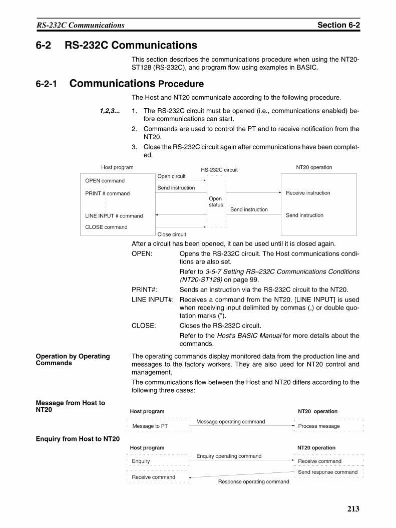
RS-232C Communications Section 6-2
6-2 RS-232C CommunicationsThis section describes the communications procedure when using the NT20-ST128 (RS-232C), and program flow using examples in BASIC.
6-2-1 Communications ProcedureThe Host and NT20 communicate according to the following procedure.
1,2,3... 1. The RS-232C circuit must be opened (i.e., communications enabled) be-fore communications can start.
2. Commands are used to control the PT and to receive notification from theNT20.
3. Close the RS-232C circuit again after communications have been complet-ed.
After a circuit has been opened, it can be used until it is closed again.
OPEN: Opens the RS-232C circuit. The Host communications condi-tions are also set.
Refer to 3-5-7 Setting RS–232C Communications Conditions(NT20-ST128) on page 99.
PRINT#: Sends an instruction via the RS-232C circuit to the NT20.
LINE INPUT#: Receives a command from the NT20. [LINE INPUT] is usedwhen receiving input delimited by commas (,) or double quo-tation marks (").
CLOSE: Closes the RS-232C circuit.
Refer to the Host's BASIC Manual for more details about thecommands.
Operation by Operating Commands
The operating commands display monitored data from the production line andmessages to the factory workers. They are also used for NT20 control andmanagement.
The communications flow between the Host and NT20 differs according to thefollowing three cases:
Message from Host to NT20
Enquiry from Host to NT20
Host program RS-232C circuit NT20 operation
OPEN command
PRINT # command
LINE INPUT # command
CLOSE command
Open circuit
Send instruction
Close circuit
Send instruction
Receive instruction
Send instruction
Open status
Host program NT20 operation
Message to PT Process messageMessage operating command
Host program NT20 operation
Enquiry operating commandEnquiry
Receive command
Receive command
Send response command
Response operating command
213
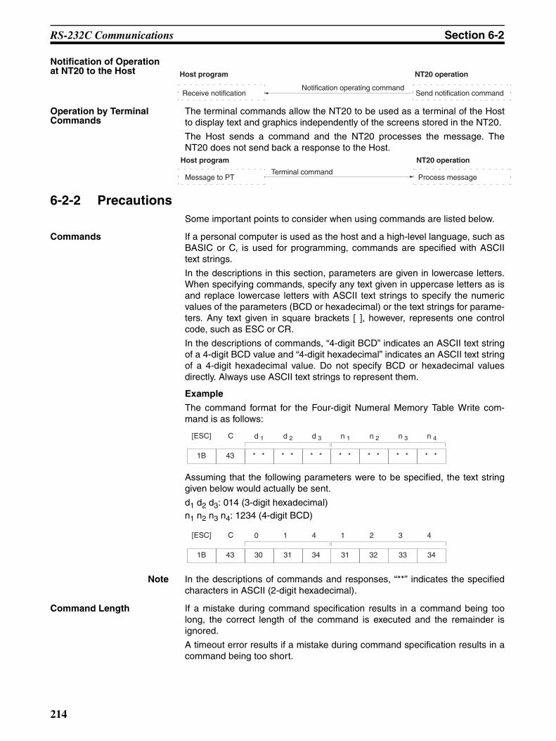
RS-232C Communications Section 6-2
Notification of Operation at NT20 to the Host
Operation by Terminal Commands
The terminal commands allow the NT20 to be used as a terminal of the Hostto display text and graphics independently of the screens stored in the NT20.
The Host sends a command and the NT20 processes the message. TheNT20 does not send back a response to the Host.
6-2-2 PrecautionsSome important points to consider when using commands are listed below.
Commands If a personal computer is used as the host and a high-level language, such asBASIC or C, is used for programming, commands are specified with ASCIItext strings.
In the descriptions in this section, parameters are given in lowercase letters.When specifying commands, specify any text given in uppercase letters as isand replace lowercase letters with ASCII text strings to specify the numericvalues of the parameters (BCD or hexadecimal) or the text strings for parame-ters. Any text given in square brackets [ ], however, represents one controlcode, such as ESC or CR.
In the descriptions of commands, “4-digit BCD” indicates an ASCII text stringof a 4-digit BCD value and “4-digit hexadecimal” indicates an ASCII text stringof a 4-digit hexadecimal value. Do not specify BCD or hexadecimal valuesdirectly. Always use ASCII text strings to represent them.
Example
The command format for the Four-digit Numeral Memory Table Write com-mand is as follows:
Assuming that the following parameters were to be specified, the text stringgiven below would actually be sent.
d1 d2 d3: 014 (3-digit hexadecimal)n1 n2 n3 n4: 1234 (4-digit BCD)
Note In the descriptions of commands and responses, “**” indicates the specifiedcharacters in ASCII (2-digit hexadecimal).
Command Length If a mistake during command specification results in a command being toolong, the correct length of the command is executed and the remainder isignored.
A timeout error results if a mistake during command specification results in acommand being too short.
Host program NT20 operation
Receive notificationNotification operating command
Send notification command
Host program NT20 operation
Message to PTTerminal command
Process message
1B
[ESC]
43
C d 1 d 2
* * * *
d 3
* * * * * * * * * *
n 1 n 2 n 3 n 4
1B
[ESC]
43
C 0 1 4 1 2 3 4
30 31 34 31 32 33 34
214

RS-232C Communications Section 6-2
Interval between Transmitted Commands
As a small number of bytes is transmitted by the Host, the interval betweentransmissions should not exceed 5 seconds if a command is divided up fortransmission. A timeout error occurs if the interval between transmissionsexceeds 5 seconds.
When commands are sent too frequently, a buffer overflow error may occur ifthe NT20 cannot keep up with the command processing.
In order to prevent buffer overflow, use flow control.
Controlling PT Status with Operating Commands
Control of the NT20 status by the operating commands is restricted by theNT20 memory switch settings as listed below.
Coordinate Specification with the Terminal Commands
The entire command is ignored if any point specified at coordinates X, Y withthe Terminal commands lies outside the screen.
Error Display If the “automatic reset after communications” memory switch of the NT20 isset to ON, no message is displayed when a communications error occurs.
However, time-out errors are displayed.
Operating command Restriction from memory switch setting
Buzzer control command [ESC] T Effective when “buzzer turned on”
215
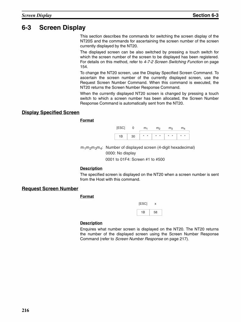
Screen Display Section 6-3
6-3 Screen DisplayThis section describes the commands for switching the screen display of theNT20S and the commands for ascertaining the screen number of the screencurrently displayed by the NT20.
The displayed screen can be also switched by pressing a touch switch forwhich the screen number of the screen to be displayed has been registered.For details on this method, refer to 4-7-2 Screen Switching Function on page154.
To change the NT20 screen, use the Display Specified Screen Command. Toascertain the screen number of the currently displayed screen, use theRequest Screen Number Command. When this command is executed, theNT20 returns the Screen Number Response Command.
When the currently displayed NT20 screen is changed by pressing a touchswitch to which a screen number has been allocated, the Screen NumberResponse Command is automatically sent from the NT20.
Display Specified Screen
Format
Description
The specified screen is displayed on the NT20 when a screen number is sentfrom the Host with this command.
Request Screen Number
Format
Description
Enquires what number screen is displayed on the NT20. The NT20 returnsthe number of the displayed screen using the Screen Number ResponseCommand (refer to Screen Number Response on page 217).
1B
[ESC]
30
0 m1 m2
* * * *
m3
* *
m4
* *
m1m2m3m4: Number of displayed screen (4-digit hexadecimal)0000: No display
0001 to 01F4: Screen #1 to #500
1B
[ESC]
58
x
216
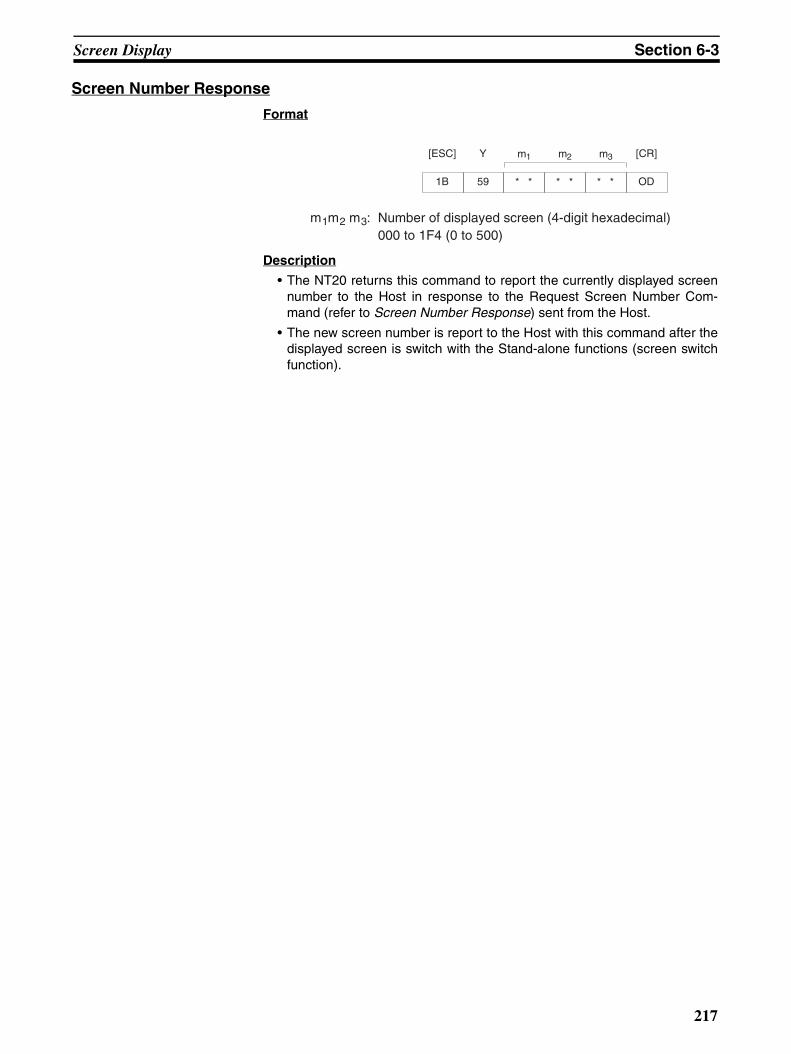
Screen Display Section 6-3
Screen Number Response
Format
Description
• The NT20 returns this command to report the currently displayed screennumber to the Host in response to the Request Screen Number Com-mand (refer to Screen Number Response) sent from the Host.
• The new screen number is report to the Host with this command after thedisplayed screen is switch with the Stand-alone functions (screen switchfunction).
1B
[ESC]
59
Y m1
* *
m2
* *
m3
* * OD
[CR]
m1m2 m3: Number of displayed screen (4-digit hexadecimal)000 to 1F4 (0 to 500)
217

Memory Tables Section 6-4
6-4 Memory TablesThis section explains the commands used for memory table operations.
To change the contents of a character string memory table entry, use theWrite Character-string Memory Table Command.
To change the contents of a numeral memory table entry, use a WriteNumeral Memory Table Command.
Note that different commands are used to write 4-digit and 8-digit numericalvalues.
Values can be copied from one memory table entry to another of the sametype by using the Copy Memory Table Command.
Reference
• When the contents of an NT20 numeral memory table entry are changedby numeral setting input, a Number Input Notify Command is automati-cally sent from the NT20 (refer to 6-5-2 Notification of Numeral SettingInput and Touch Switch Status).
• By creating a bar graph screen and arranging for it to refer to a particularnumeral memory table entry, the display contents of the bar graph can beupdated by changing the contents of the numeral table entry.
Write Character-string Memory Table
Format
Description
Writes the character-string data to the character-string memory table entry.
The character-string data can contain a mixture of normal alphanumeric char-acters and marks. When determining the character string length, count eachmark as two normal characters.
!Caution If the actual character string is longer than the specified character stringlength, the specified number of characters is written and the remainder arediscarded.A timeout error message is displayed if the actual character string is shorterthan the specified character string length.
1B
[ESC]
42
B n1
* *
n2
* *
d1
* *
d2
* *
c1
* *
c2
* *
c3
* *
cn
* *
n1n2: Character string length as a number of normal characters (2-digit hexade-cimal) 01 to 20H (1 to 32)
d1d2: Character-string memory table entry number of write destination (2-digit hexa-decimal) 00 to 7FH (0 to 127)
c1c2c3 to c n: Character-string data
218
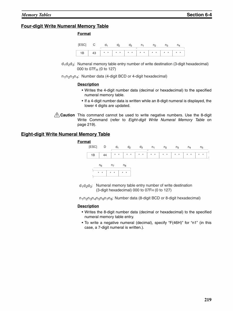
Memory Tables Section 6-4
Four-digit Write Numeral Memory Table
Format
Description
• Writes the 4-digit number data (decimal or hexadecimal) to the specifiednumeral memory table.
• If a 4-digit number data is written while an 8-digit numeral is displayed, thelower 4 digits are updated.
!Caution This command cannot be used to write negative numbers. Use the 8-digitWrite Command (refer to Eight-digit Write Numeral Memory Table onpage 219).
Eight-digit Write Numeral Memory Table
Format
Description
• Writes the 8-digit number data (decimal or hexadecimal) to the specifiednumeral memory table entry.
• To write a negative numeral (decimal), specify “F(46H)” for “n1” (in thiscase, a 7-digit numeral is written.).
1B
[ESC]
43
C d1
* *
d2
* *
d3
* *
n1
* *
n2
* *
n3
* *
n4
* *
d1d2d3:000 to 07FH (0 to 127)
n1n2n3n4: Number data (4-digit BCD or 4-digit hexadecimal)
Numeral memory table entry number of write destination (3-digit hexadecimal)
1B
[ESC]
44
D d1
* *
d2
* *
n1
* *
n2
* *
n3
* *
n4
* *
d3
* *
n6
* *
n7
* *
n8
* *
n5
**
d1d2d3: Numeral memory table entry number of write destination (3-digit hexadecimal) 000 to 07FH (0 to 127)
n1n2n3n4n5n6n7n8: Number data (8-digit BCD or 8-digit hexadecimal)
219

Memory Tables Section 6-4
Copy Memory Table Format
Description
Copies the contents of the copy source memory table entry to the copy desti-nation memory table entry. The memory table entry contents are copied to amemory table entry of the same type: character-string memory table entry tocharacter-string memory table entry or numeral memory table entry tonumeral memory table entry .
1B
[ESC] s1
* *
s2
* *
d1
* *
d2
* *
d3
* *
m1
* *
s3
* *2F
/
m1: Type of memory table0 (30H): Character-string memory table1 (31H): Numeral memory table
s1s2s3: Copy source memory table entry number000 to 127 (3-digit BCD)
d1d2d3: Copy destination memory table entry number000 to 127 (3-digit BCD)
220
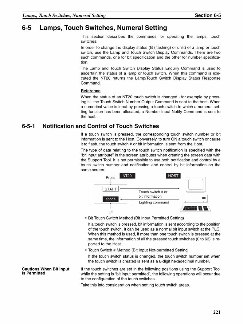
Lamps, Touch Switches, Numeral Setting Section 6-5
6-5 Lamps, Touch Switches, Numeral SettingThis section describes the commands for operating the lamps, touchswitches.
In order to change the display status (lit (flashing) or unlit) of a lamp or touchswitch, use the Lamp and Touch Switch Display Commands. There are twosuch commands, one for bit specification and the other for number specifica-tion.
The Lamp and Touch Switch Display Status Enquiry Command is used toascertain the status of a lamp or touch switch. When this command is exe-cuted the NT20 returns the Lamp/Touch Switch Display Status ResponseCommand.
Reference
When the status of an NT20 touch switch is changed - for example by press-ing it - the Touch Switch Number Output Command is sent to the host. Whena numerical value is input by pressing a touch switch to which a numeral set-ting function has been allocated, a Number Input Notify Command is sent tothe host.
6-5-1 Notification and Control of Touch SwitchesIf a touch switch is pressed, the corresponding touch switch number or bitinformation is sent to the Host. Conversely, to turn ON a touch switch or causeit to flash, the touch switch # or bit information is sent from the Host.
The type of data relating to the touch switch notification is specified with the“bit input attribute” in the screen attributes when creating the screen data withthe Support Tool. It is not permissible to use both notification and control by atouch switch number and notification and control by bit information on thesame screen.
• Bit Touch Switch Method (Bit Input Permitted Setting)
If a touch switch is pressed, bit information is sent according to the positionof the touch switch. It can be used as a normal bit input switch at the PLC.When this method is used, if more than one touch switch is pressed at thesame time, the information of all the pressed touch switches (0 to 63) is re-ported to the Host.
• Touch Switch # Method (Bit Input Not-permitted Setting
If the touch switch status is changed, the touch switch number set whenthe touch switch is created is sent as a 8-digit hexadecimal number.
Cautions When Bit Input Is Permitted
If the touch switches are set in the following positions using the Support Toolwhile the setting is “bit input permitted”, the following operations will occur dueto the configuration of the touch switches.
Take this into consideration when setting touch switch areas.
Press
Lit
Touch switch # or bit information
Lighting command
START
abcde
NT20 HOST
221
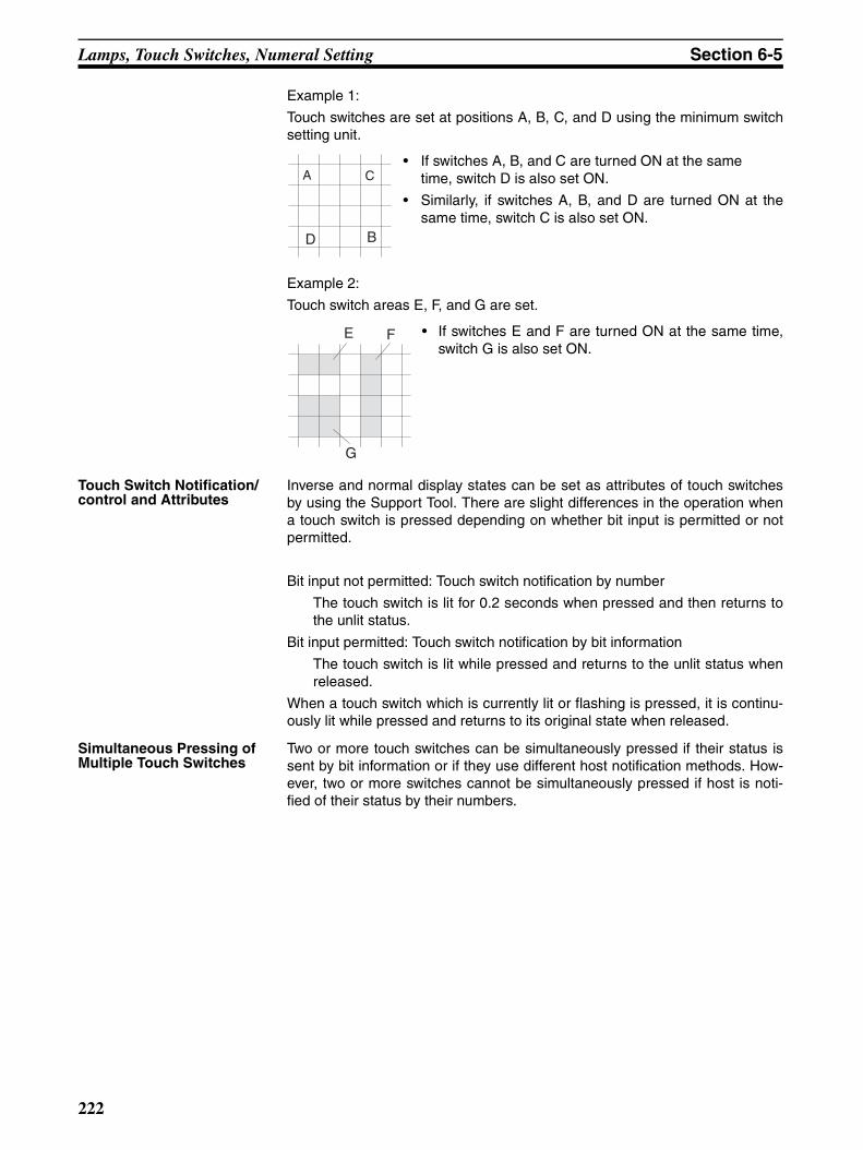
Lamps, Touch Switches, Numeral Setting Section 6-5
Example 1:
Touch switches are set at positions A, B, C, and D using the minimum switchsetting unit.
• If switches A, B, and C are turned ON at the sametime, switch D is also set ON.
• Similarly, if switches A, B, and D are turned ON at thesame time, switch C is also set ON.
Example 2:
Touch switch areas E, F, and G are set.
• If switches E and F are turned ON at the same time,switch G is also set ON.
Touch Switch Notification/control and Attributes
Inverse and normal display states can be set as attributes of touch switchesby using the Support Tool. There are slight differences in the operation whena touch switch is pressed depending on whether bit input is permitted or notpermitted.
Bit input not permitted: Touch switch notification by number
The touch switch is lit for 0.2 seconds when pressed and then returns tothe unlit status.
Bit input permitted: Touch switch notification by bit information
The touch switch is lit while pressed and returns to the unlit status whenreleased.
When a touch switch which is currently lit or flashing is pressed, it is continu-ously lit while pressed and returns to its original state when released.
Simultaneous Pressing of Multiple Touch Switches
Two or more touch switches can be simultaneously pressed if their status issent by bit information or if they use different host notification methods. How-ever, two or more switches cannot be simultaneously pressed if host is noti-fied of their status by their numbers.
D B
A C
G
E F
222
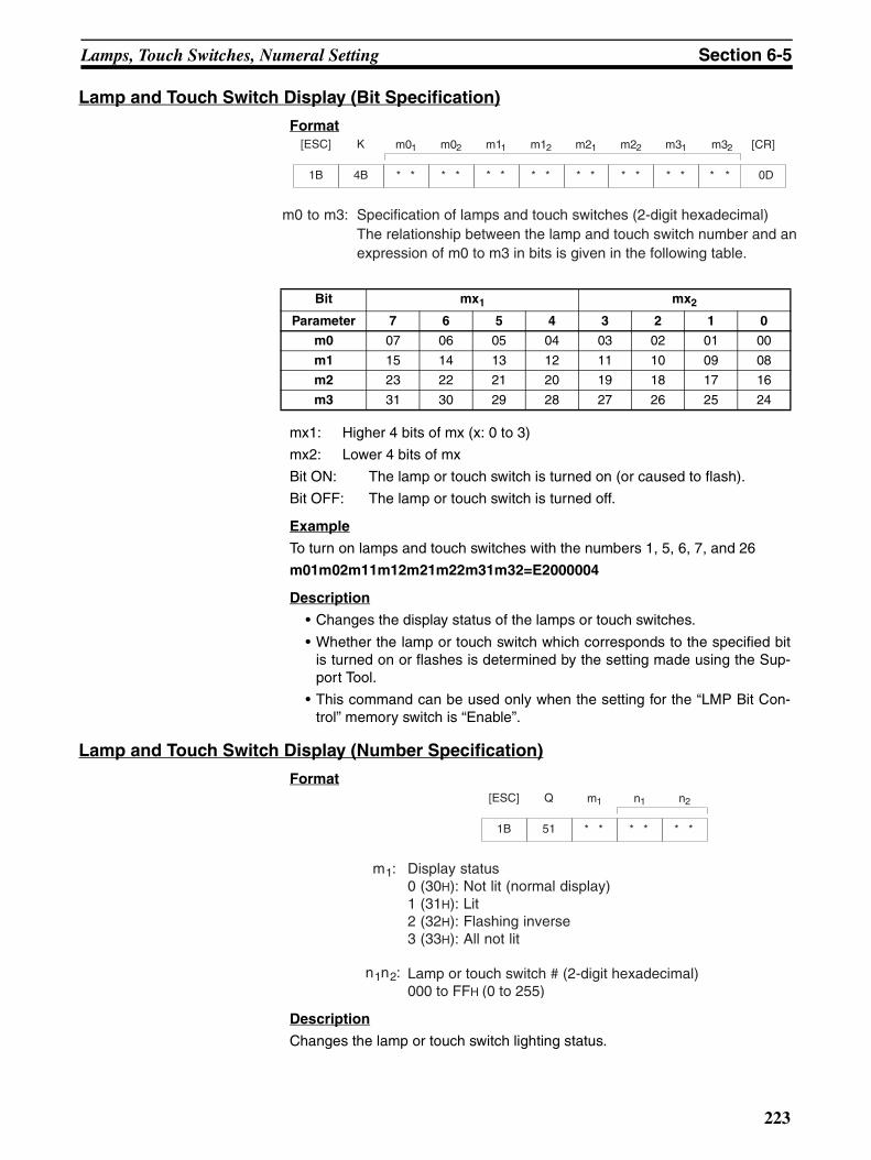
Lamps, Touch Switches, Numeral Setting Section 6-5
Lamp and Touch Switch Display (Bit Specification)
Format
mx1: Higher 4 bits of mx (x: 0 to 3)
mx2: Lower 4 bits of mx
Bit ON: The lamp or touch switch is turned on (or caused to flash).
Bit OFF: The lamp or touch switch is turned off.
Example
To turn on lamps and touch switches with the numbers 1, 5, 6, 7, and 26
m01m02m11m12m21m22m31m32=E2000004
Description
• Changes the display status of the lamps or touch switches.
• Whether the lamp or touch switch which corresponds to the specified bitis turned on or flashes is determined by the setting made using the Sup-port Tool.
• This command can be used only when the setting for the “LMP Bit Con-trol” memory switch is “Enable”.
Lamp and Touch Switch Display (Number Specification)
Format
Description
Changes the lamp or touch switch lighting status.
Bit mx1 mx2
Parameter 7 6 5 4 3 2 1 0
m0 07 06 05 04 03 02 01 00
m1 15 14 13 12 11 10 09 08
m2 23 22 21 20 19 18 17 16
m3 31 30 29 28 27 26 25 24
1B
[ESC]
4B
K m01
* *
m02
* *
m12
* *
m21
* *
m22
* *
m31
* *
m11
* *
m32
**
[CR]
0D
m0 to m3: Specification of lamps and touch switches (2-digit hexadecimal)The relationship between the lamp and touch switch number and anexpression of m0 to m3 in bits is given in the following table.
1B
[ESC] n1
* *
n2
* *
m1
* *51
Q
m1: Display status0 (30H): Not lit (normal display)1 (31H): Lit2 (32H): Flashing inverse3 (33H): All not lit
n1n2: Lamp or touch switch # (2-digit hexadecimal)000 to FFH (0 to 255)
223
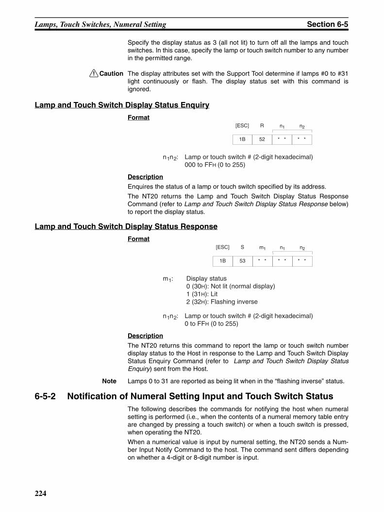
Lamps, Touch Switches, Numeral Setting Section 6-5
Specify the display status as 3 (all not lit) to turn off all the lamps and touchswitches. In this case, specify the lamp or touch switch number to any numberin the permitted range.
!Caution The display attributes set with the Support Tool determine if lamps #0 to #31light continuously or flash. The display status set with this command isignored.
Lamp and Touch Switch Display Status Enquiry
Format
Description
Enquires the status of a lamp or touch switch specified by its address.
The NT20 returns the Lamp and Touch Switch Display Status ResponseCommand (refer to Lamp and Touch Switch Display Status Response below)to report the display status.
Lamp and Touch Switch Display Status Response
Format
Description
The NT20 returns this command to report the lamp or touch switch numberdisplay status to the Host in response to the Lamp and Touch Switch DisplayStatus Enquiry Command (refer to Lamp and Touch Switch Display StatusEnquiry) sent from the Host.
Note Lamps 0 to 31 are reported as being lit when in the “flashing inverse” status.
6-5-2 Notification of Numeral Setting Input and Touch Switch StatusThe following describes the commands for notifying the host when numeralsetting is performed (i.e., when the contents of a numeral memory table entryare changed by pressing a touch switch) or when a touch switch is pressed,when operating the NT20.
When a numerical value is input by numeral setting, the NT20 sends a Num-ber Input Notify Command to the host. The command sent differs dependingon whether a 4-digit or 8-digit number is input.
1B
[ESC] n1
* *
n2
* *52
R
n1n2: Lamp or touch switch # (2-digit hexadecimal)000 to FFH (0 to 255)
1B
[ESC] n1
* *
n2
* *
m1
* *53
S
m1: Display status0 (30H): Not lit (normal display)1 (31H): Lit2 (32H): Flashing inverse
n1n2: Lamp or touch switch # (2-digit hexadecimal)0 to FFH (0 to 255)
224
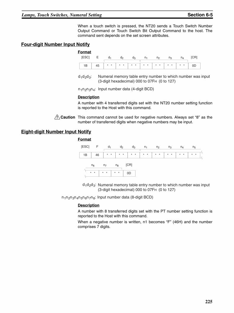
Lamps, Touch Switches, Numeral Setting Section 6-5
When a touch switch is pressed, the NT20 sends a Touch Switch NumberOutput Command or Touch Switch Bit Output Command to the host. Thecommand sent depends on the set screen attributes.
Four-digit Number Input Notify
Format
Description
A number with 4 transferred digits set with the NT20 number setting functionis reported to the Host with this command.
!Caution This command cannot be used for negative numbers. Always set “8” as thenumber of transferred digits when negative numbers may be input.
Eight-digit Number Input Notify
Format
Description
A number with 8 transferred digits set with the PT number setting function isreported to the Host with this command.
When a negative number is written, n1 becomes “F” (46H) and the numbercomprises 7 digits.
1B
[ESC]
45
E d1
* *
d2
* *
n1
* *
n2
* *
n3
* *
n4
* *
d3
* * 0D
[CR]
d1d2d3: Numeral memory table entry number to which number was input (3-digit hexadecimal) 000 to 07FH (0 to 127)
n1n2n3n4: Input number data (4-digit BCD)
1B
[ESC]
46
F d1
* *
d2
* *
n1
* *
n2
* *
n3
* *
n4
* *
d3
* *
n6
* *
n7
* *
n8
* * 0D
[CR]
n5
* *
d1d2d3:
n1n2n3n4n5n6n7n8: Input number data (8-digit BCD)
Numeral memory table entry number to which number was input (3-digit hexadecimal) 000 to 07FH (0 to 127)
225
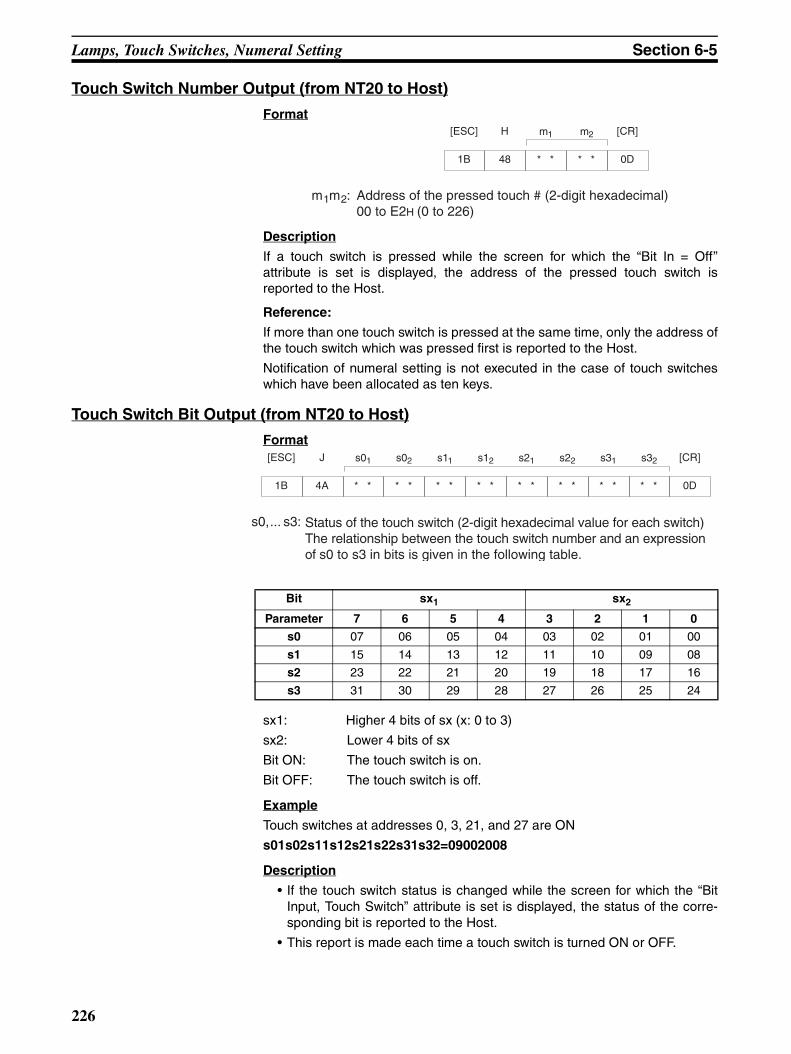
Lamps, Touch Switches, Numeral Setting Section 6-5
Touch Switch Number Output (from NT20 to Host)
Format
Description
If a touch switch is pressed while the screen for which the “Bit In = Off”attribute is set is displayed, the address of the pressed touch switch isreported to the Host.
Reference:
If more than one touch switch is pressed at the same time, only the address ofthe touch switch which was pressed first is reported to the Host.
Notification of numeral setting is not executed in the case of touch switcheswhich have been allocated as ten keys.
Touch Switch Bit Output (from NT20 to Host)
Format
sx1: Higher 4 bits of sx (x: 0 to 3)
sx2: Lower 4 bits of sx
Bit ON: The touch switch is on.
Bit OFF: The touch switch is off.
Example
Touch switches at addresses 0, 3, 21, and 27 are ON
s01s02s11s12s21s22s31s32=09002008
Description
• If the touch switch status is changed while the screen for which the “BitInput, Touch Switch” attribute is set is displayed, the status of the corre-sponding bit is reported to the Host.
• This report is made each time a touch switch is turned ON or OFF.
1B
[ESC]
48
H m1
* *
m2
* * 0D
[CR]
m1m2: Address of the pressed touch # (2-digit hexadecimal)00 to E2H (0 to 226)
Bit sx1 sx2
Parameter 7 6 5 4 3 2 1 0
s0 07 06 05 04 03 02 01 00
s1 15 14 13 12 11 10 09 08
s2 23 22 21 20 19 18 17 16
s3 31 30 29 28 27 26 25 24
1B
[ESC]
4A
J s01
* *
s02
* *
s12
* *
s21
* *
s22
* *
s31
* *
s11
* * 0D
[CR]s32
* *
s0,... s3: Status of the touch switch (2-digit hexadecimal value for each switch)The relationship between the touch switch number and an expression of s0 to s3 in bits is given in the following table.
226

Controlling the NT20 Status Section 6-6
6-6 Controlling the NT20 StatusThis section describes the actual methods used for controlling the NT20 sta-tus.
The Screen Display Control Command is used to operate the back light of theNT20 (i.e., switch it on and off).
The Buzzer Control Command is used to control the buzzer status of theNT20. To inhibit the display of the system menu or cancel this inhibition, usethe Mode Switch Enable Command.
Touch switch data input or host notification can be inhibited, or this inhibitioncanceled, by using the Touch Switch and Function Key Disable Command orTouch Switch and Function Key Enable Command respectively.
Touch Switch Disable Format
Description
Disables touch switch and function key input and notification to the Host.
Reference:
Use the Touch Switch Enable Command (refer to Touch Switch Enable) to usea disabled touch switch again. Disabled touch switches are also enabledwhen the NT20 power is turned off.
Touch Switch Enable Format
Description
Enables input and notification to the Host of a disabled touch switch or func-tion key.
Reference:
Disabled touch switches are also enabled when the NT20 power is turned off.
Screen Display Control
Format
Description
Turns off the backlighting.
Reference:
The screen is redisplayed if a touch switch is pressed.
When a Display Specified Screen Command on page 216 is sent, the speci-fied screen is displayed.
1B
[ESC] 2
55
U
32
1B
[ESC] 2
56
V
32
1B
[ESC] m1
* *50
P
m1: Display on or off0 (30H): on 1 (31H): off
227
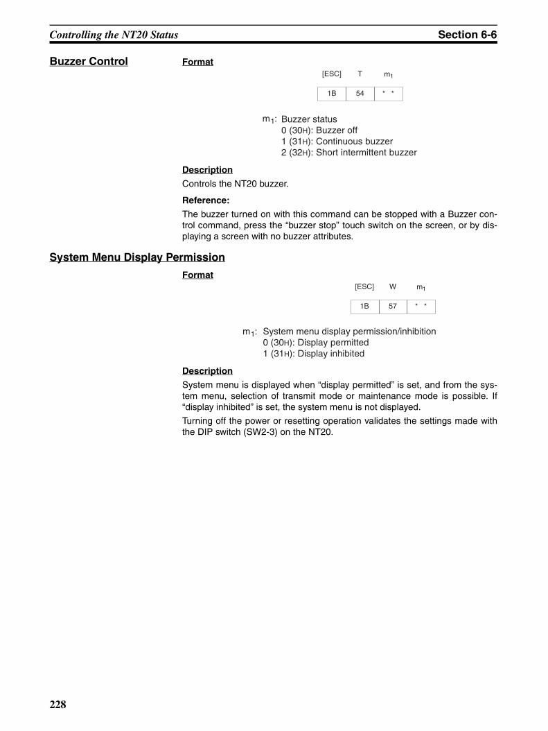
Controlling the NT20 Status Section 6-6
Buzzer Control Format
Description
Controls the NT20 buzzer.
Reference:
The buzzer turned on with this command can be stopped with a Buzzer con-trol command, press the “buzzer stop” touch switch on the screen, or by dis-playing a screen with no buzzer attributes.
System Menu Display Permission
Format
Description
System menu is displayed when “display permitted” is set, and from the sys-tem menu, selection of transmit mode or maintenance mode is possible. If“display inhibited” is set, the system menu is not displayed.
Turning off the power or resetting operation validates the settings made withthe DIP switch (SW2-3) on the NT20.
1B
[ESC] m1
* *54
T
m1: Buzzer status 0 (30H): Buzzer off 1 (31H): Continuous buzzer 2 (32H): Short intermittent buzzer
1B
[ESC]
57
W m1
* *
m1: System menu display permission/inhibition0 (30H): Display permitted 1 (31H): Display inhibited
228
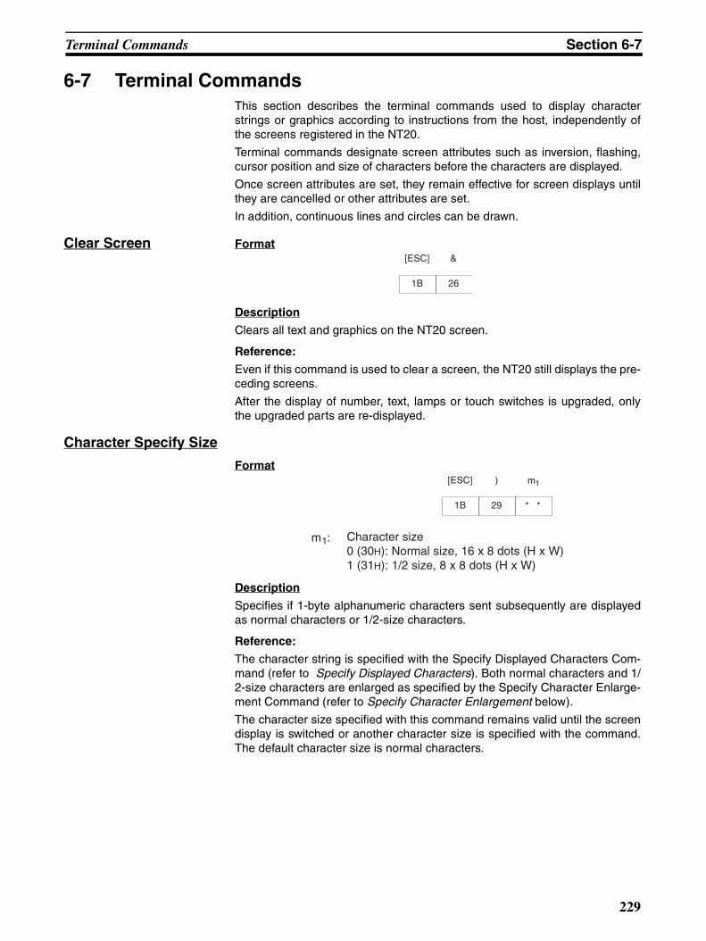
Terminal Commands Section 6-7
6-7 Terminal CommandsThis section describes the terminal commands used to display characterstrings or graphics according to instructions from the host, independently ofthe screens registered in the NT20.
Terminal commands designate screen attributes such as inversion, flashing,cursor position and size of characters before the characters are displayed.
Once screen attributes are set, they remain effective for screen displays untilthey are cancelled or other attributes are set.
In addition, continuous lines and circles can be drawn.
Clear Screen Format
Description
Clears all text and graphics on the NT20 screen.
Reference:
Even if this command is used to clear a screen, the NT20 still displays the pre-ceding screens.
After the display of number, text, lamps or touch switches is upgraded, onlythe upgraded parts are re-displayed.
Character Specify Size
Format
Description
Specifies if 1-byte alphanumeric characters sent subsequently are displayedas normal characters or 1/2-size characters.
Reference:
The character string is specified with the Specify Displayed Characters Com-mand (refer to Specify Displayed Characters). Both normal characters and 1/2-size characters are enlarged as specified by the Specify Character Enlarge-ment Command (refer to Specify Character Enlargement below).
The character size specified with this command remains valid until the screendisplay is switched or another character size is specified with the command.The default character size is normal characters.
1B
[ESC]
26
&
1B
[ESC] m1
* *29
)
m1: Character size 0 (30H): Normal size, 16 x 8 dots (H x W)1 (31H): 1/2 size, 8 x 8 dots (H x W)
229
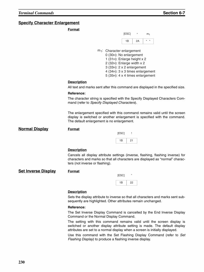
Terminal Commands Section 6-7
Specify Character Enlargement
Format
Description
All text and marks sent after this command are displayed in the specified size.
Reference:
The character string is specified with the Specify Displayed Characters Com-mand (refer to Specify Displayed Characters).
The enlargement specified with this command remains valid until the screendisplay is switched or another enlargement is specified with the command.The default enlargement is no enlargement.
Normal Display Format
Description
Cancels all display attribute settings (inverse, flashing, flashing inverse) forcharacters and marks so that all characters are displayed as “normal” charac-ters (not inverse or flashing).
Set Inverse Display Format
Description
Sets the display attribute to inverse so that all characters and marks sent sub-sequently are highlighted. Other attributes remain unchanged.
Reference:
The Set Inverse Display Command is cancelled by the End Inverse DisplayCommand or the Normal Display Command.
The setting with this command remains valid until the screen display isswitched or another display attribute setting is made. The default displayattributes are set to a normal display when a screen is initially displayed.
Use this command with the Set Flashing Display Command (refer to SetFlashing Display) to produce a flashing inverse display.
1B
[ESC] m1
* *2A
*
m1: Character enlargement 0 (30H): No enlargement 1 (31H): Enlarge height x 2 2 (32H): Enlarge width x 2 3 (33H): 2 x 2 enlargement 4 (34H): 3 x 3 times enlargement5 (35H): 4 x 4 times enlargement
1B
[ESC]
21
!
1B
[ESC]
22
”
230
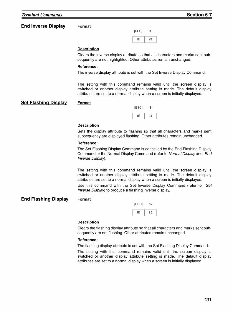
Terminal Commands Section 6-7
End Inverse Display Format
Description
Clears the inverse display attribute so that all characters and marks sent sub-sequently are not highlighted. Other attributes remain unchanged.
Reference:
The inverse display attribute is set with the Set Inverse Display Command.
The setting with this command remains valid until the screen display isswitched or another display attribute setting is made. The default displayattributes are set to a normal display when a screen is initially displayed.
Set Flashing Display Format
Description
Sets the display attribute to flashing so that all characters and marks sentsubsequently are displayed flashing. Other attributes remain unchanged.
Reference:
The Set Flashing Display Command is cancelled by the End Flashing DisplayCommand or the Normal Display Command (refer to Normal Display and EndInverse Display).
The setting with this command remains valid until the screen display isswitched or another display attribute setting is made. The default displayattributes are set to a normal display when a screen is initially displayed.
Use this command with the Set Inverse Display Command (refer to SetInverse Display) to produce a flashing inverse display.
End Flashing Display Format
Description
Clears the flashing display attribute so that all characters and marks sent sub-sequently are not flashing. Other attributes remain unchanged.
Reference:
The flashing display attribute is set with the Set Flashing Display Command.
The setting with this command remains valid until the screen display isswitched or another display attribute setting is made. The default displayattributes are set to a normal display when a screen is initially displayed.
1B
[ESC]
23
#
1B
[ESC]
24
$
1B
[ESC]
25
%
231

Terminal Commands Section 6-7
Set Cursor Position Format
Description
Before displaying a character string with the Terminal commands, use thiscommand to set the bottom-left point of the first character to be displayed.
Reference:
The cursor position set with this command is also the bottom-left point of thefirst character displayed if the displayed characters are enlarged.
Specify Displayed Characters
Format
Description
• The character string is displayed from the cursor position.
• The character-string data can contain a mixture of normal (alphanumeric)characters and marks. Refer to Appendix H Special Characters for details.
• The character string is displayed according to the enlargement and dis-play attributes set with commands.
Reference:
The character string continues on the next line if it cannot fit into a single line.
Set the position where the character string is displayed with the Set CursorPosition Command (refer to Set Cursor Position).
1B
[ESC]
2B
+ x1
* *
x2
* *
x3
* *
y1
* *
y2
* *
y3
* *
x1x2x3: X coordinate (3-digit BCD)000 to 255
y1y2y3: Y coordinate (3-digit BCD)000 to 127
1B
[ESC]
34
4 n1
* *
n2
* *
c1
* *
c2
* *
cn
* *
c3
* *
n1n2: Character string length as a number of normal characters(2-digit hexadecimal) 01 to 20H (1 to 32)
c1c2c3 to c n: Character-string to display
232
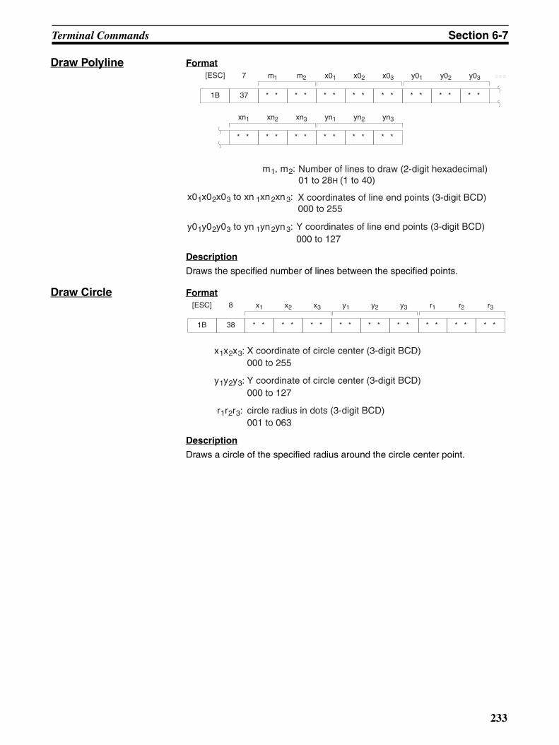
Terminal Commands Section 6-7
Draw Polyline Format
Description
Draws the specified number of lines between the specified points.
Draw Circle Format
Description
Draws a circle of the specified radius around the circle center point.
1B
[ESC]
37
7 m1
* *
m2
* *
x01
* *
x02
* *
x03
* *
y01
* *
y02
* *
y03
* *
xn1
* *
xn2
* *
xn3
* *
yn1
* *
yn2
* *
yn3
* *
m1, m2: Number of lines to draw (2-digit hexadecimal) 01 to 28H (1 to 40)
x01x02x03 to xn 1xn2xn3: X coordinates of line end points (3-digit BCD) 000 to 255
y01y02y03 to yn 1yn2yn3: Y coordinates of line end points (3-digit BCD)000 to 127
1B
[ESC]
38
8 x1
* *
x2
* *
x3
* *
y1
* *
y2
* *
y3
* *
r1
* *
r2
* *
r3
* *
x1x2x3: X coordinate of circle center (3-digit BCD)000 to 255
y1y2y3: Y coordinate of circle center (3-digit BCD)000 to 127
r1r2r3: circle radius in dots (3-digit BCD)001 to 063
233

Key to Programs Section 6-8
6-8 Key to ProgramsThe following programs include all the commands that can be used with theNT20.
6-8-1 Use of ProgramsThe sample program appears as follows on the screen.
1. This sample program is written in N88BASIC (86) (NEC) for a PC-9801computer. Modify this program for use with any other computer languageor computer such as an IBM PC/AT or compatible.
2. The interval between parameter input and command transmission is a holdinterval for interrupt processing of the received command. If an interrupt ispermitted between the interval of parameter input and a command is re-ceived, all subsequent receive interrupts are displaced. If this occurs, sendan enquiry command to read all the accumulated receive data.
3. When a parameter is input, no check is made that the parameter is in thepermitted range. Make sure that parameters are input within the permittedrange.
Send command column
Menu bar Sub-menu Parameter input column
Run confirm column
Receive commanddisplay column
Use the program as shown below.
Interrupt display when command received
[ESC]
[ESC]
[ESC]
Execute program
Select type of sendcommand
Select send command
Input parameter
Confirm send command
Execute transfercommand
End program
Main Menu
Sub-menu
Input parameter column
Send command column,confirm execution
Up, Down, Left, Right keys: select item[ENT]: confirm[Esc]: stop
234

Key to Programs Section 6-8
Example Program
1000 ’ ********************************************************
1010 ’ * OPERATION COMMAND EXAMPLE PROGRAM (NT20-ST128)*
1020 ’ ********************************************************
1030 ’ Draw screen frame. . . . . . . . . . . . . . . . . . . . . . . . . . . . . . . . . . . . . . . . . . . .
1040 SECT=9
1050 DIM CMND$(SECT,10,1),CMND(SECT),TS.B(31)
1060 SCREEN 3:CLS 3:CONSOLE 15,10,0,0
1070 LINE (0,176)–(639,176),7,,&HF0F0
1080 LINE (159,0)–(159,176),7,,&HF0F0
1090 LINE (300,0)–(300,176),7,,&HF0F0
1100 LINE (0, 16)–(159, 16),7,,&HF0F0
1110 LINE (0, 96)–(159, 96),7,,&HF0F0
1120 LINE (0,112)–(159,112),7,,&HF0F0
1130 LINE (520,176)–(520,224),7,,&HF0F0
1140 LINE (0,223)–(639,224),7,B
1150 COLOR 0:LOCATE 2,0:PRINT ”OPERATING COMMANDS”
1160 COLOR 0:LOCATE 2,6:PRINT ”TERMINAL COMMANDS”
1170 CMND(0)=SECT ’ Set display character strings. . . . . . . . . . . . . . . . . . . . . . . . . . . .
1180 FOR I=1 TO SECT
1190 READ CMND$(0,I,0)
1200 NEXT I
1210 FOR I=1 TO SECT
1220 READ CMND(I)
1230 FOR J=1 TO CMND(I)
1240 READ CMND$(I,J,0),CMND$(I,J,1)
1250 IF CMND$(I,J,1) = ”@@@@@@” THEN CMND$(I,J,1) = ”[ESC]”+CHR$(&H22)
1260 NEXT J
1270 NEXT I
1280 ’
1290 RY=15
1300 ON COM(1) GOSUB *RECV ’ Set receive interrupt routine. . . . . . . . . . . . . . . . . .
1310 OPEN ”COM1:E81NN” AS #1 ’ Open communications port. . . . . . . . . . . . . . .
1320 ’ NT20_SETTING OF RS-232C
1330 ’ DATA BIT LENGTH 8 BITS
1340 ’ STOP BIT LENGTH 1 BIT
1350 ’ PARITY ODD
1360 ’ FLOW CONTROL RS/CS
1370 ’ BAUD RATE (VALUE SET BY SWITCH COMMAND)
1380 COM(1) ON
1390 ’
1400 *LV0 ’ Main Menu. . . . . . . . . . . . . . . . . . . . . . . . . . . . . . . . . . . . . .
1410 LV=0:SECT.NO=0:SEL.NO=1
1420 GOSUB *SELECT
1430 IF SEL.NO=0 THEN GOTO *PRO.END
235
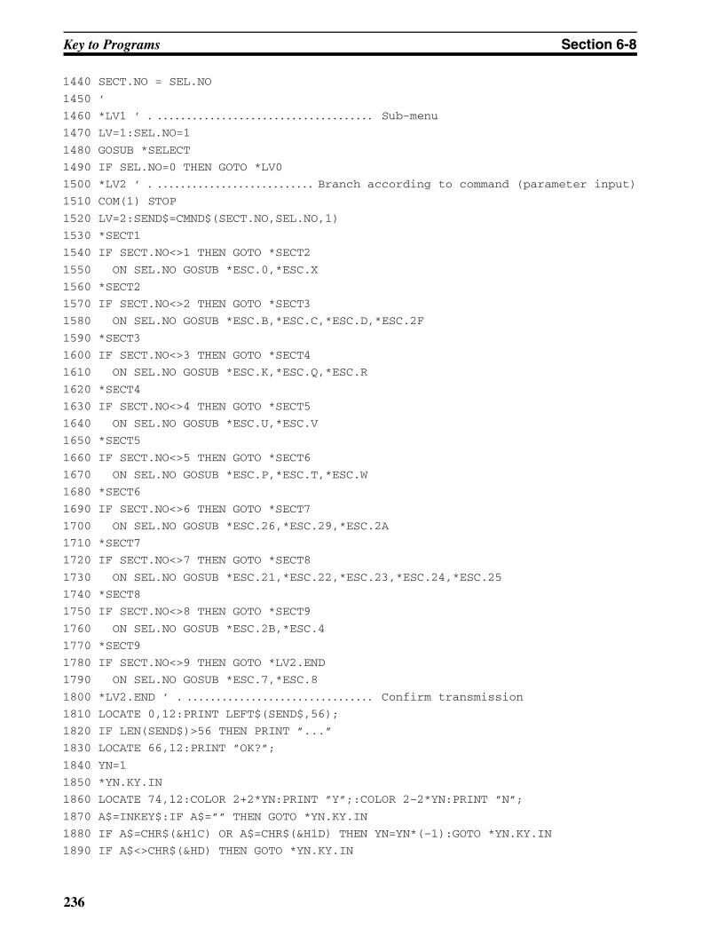
Key to Programs Section 6-8
1440 SECT.NO = SEL.NO
1450 ’
1460 *LV1 ’ Sub-menu. . . . . . . . . . . . . . . . . . . . . . . . . . . . . . . . . . . . . .
1470 LV=1:SEL.NO=1
1480 GOSUB *SELECT
1490 IF SEL.NO=0 THEN GOTO *LV0
1500 *LV2 ’ Branch according to command (parameter input). . . . . . . . . . . . . . . . . . . . . . . . . . . .
1510 COM(1) STOP
1520 LV=2:SEND$=CMND$(SECT.NO,SEL.NO,1)
1530 *SECT1
1540 IF SECT.NO<>1 THEN GOTO *SECT2
1550 ON SEL.NO GOSUB *ESC.0,*ESC.X
1560 *SECT2
1570 IF SECT.NO<>2 THEN GOTO *SECT3
1580 ON SEL.NO GOSUB *ESC.B,*ESC.C,*ESC.D,*ESC.2F
1590 *SECT3
1600 IF SECT.NO<>3 THEN GOTO *SECT4
1610 ON SEL.NO GOSUB *ESC.K,*ESC.Q,*ESC.R
1620 *SECT4
1630 IF SECT.NO<>4 THEN GOTO *SECT5
1640 ON SEL.NO GOSUB *ESC.U,*ESC.V
1650 *SECT5
1660 IF SECT.NO<>5 THEN GOTO *SECT6
1670 ON SEL.NO GOSUB *ESC.P,*ESC.T,*ESC.W
1680 *SECT6
1690 IF SECT.NO<>6 THEN GOTO *SECT7
1700 ON SEL.NO GOSUB *ESC.26,*ESC.29,*ESC.2A
1710 *SECT7
1720 IF SECT.NO<>7 THEN GOTO *SECT8
1730 ON SEL.NO GOSUB *ESC.21,*ESC.22,*ESC.23,*ESC.24,*ESC.25
1740 *SECT8
1750 IF SECT.NO<>8 THEN GOTO *SECT9
1760 ON SEL.NO GOSUB *ESC.2B,*ESC.4
1770 *SECT9
1780 IF SECT.NO<>9 THEN GOTO *LV2.END
1790 ON SEL.NO GOSUB *ESC.7,*ESC.8
1800 *LV2.END ’ Confirm transmission. . . . . . . . . . . . . . . . . . . . . . . . . . . . . . . . .
1810 LOCATE 0,12:PRINT LEFT$(SEND$,56);
1820 IF LEN(SEND$)>56 THEN PRINT ”...”
1830 LOCATE 66,12:PRINT ”OK?”;
1840 YN=1
1850 *YN.KY.IN
1860 LOCATE 74,12:COLOR 2+2*YN:PRINT ”Y”;:COLOR 2–2*YN:PRINT ”N”;
1870 A$=INKEY$:IF A$=”” THEN GOTO *YN.KY.IN
1880 IF A$=CHR$(&H1C) OR A$=CHR$(&H1D) THEN YN=YN*(–1):GOTO *YN.KY.IN
1890 IF A$<>CHR$(&HD) THEN GOTO *YN.KY.IN
236

Key to Programs Section 6-8
1900 LOCATE 66,12:COLOR 0:PRINT SPACE$(14);
1910 IF YN=–1 THEN GOTO *LV3.END
1920 GOSUB *SEND ’ Send command. . . . . . . . . . . . . . . . . . . . . . . . . . . . . .
1930 COM(1) ON
1940 LOCATE 43,9:COLOR 4:PRINT ”Press ESC Key”;:COLOR 0
1950 *SND.KY.IN
1960 A$=INKEY$:IF A$<>CHR$(&H1B) THEN *SND.KY.IN
1970 *LV3.END
1980 LOCATE 0,12:PRINT SPACE$(79);
1990 FOR I=0 TO 10
2000 LOCATE 39,I:PRINT SPACE$(40);
2010 NEXT I
2020 GOTO *LV1 ’ Return to Sub-menu. . . . . . . . . . . . . . . . . . . . . . . . . . . . . . . .
2030 ’
2040 *PRO.END ’ End routine. . . . . . . . . . . . . . . . . . . . . . . . . . . . . . . . .
2050 COM(1) OFF:CLOSE ’ Close communications port. . . . . . . . . . . . . . . . . . . . . . . .
2060 CONSOLE 0,25,0,1:CLS 3
2070 END
2080 ’
2090 *SEND ’ Send command routine. . . . . . . . . . . . . . . . . . . . . . . . . . . . . . . . . . . . .
2100 SND$=CHR$(&H1B)+MID$(SEND$,6)
2110 PRINT #1,SND$
2120 RETURN
2130 ’
2140 *RECV ’ Receive interrupt routine. . . . . . . . . . . . . . . . . . . . . . . . . . . . . . . . . . . . .
2150 IF LOC(1)=0 THEN GOTO *NORCV
2160 SX=POS(0):SY=CSRLIN
2170 LINE INPUT #1,RCV$
2180 LOCATE 0,RY:COLOR 0
2190 PRINT ”[ESC]”;MID$(RCV$,2)
2200 R.CODE$=MID$(RCV$,2,1)
2210 *ESC.Y ’ Notify screen number. . . . . . . . . . . . . . . . . . . . . . . . . . . . . . . . . . . .
2220 IF R.CODE$<>”Y” THEN GOTO *ESC.E
2230 PRINT ”Screen Number : ”;VAL(”&H”+MID$(RCV$,3,4))
2240 PRINT:GOTO *RCV.END
2250 *ESC.E ’ Notify 4-digit number. . . . . . . . . . . . . . . . . . . . . . . . . . . . . . . . . . . .
2260 IF R.CODE$<>”E” THEN GOTO *ESC.F
2270 PRINT ”Numeral table entry # : ”;VAL(”&H”+MID$(RCV$,3,3))
2280 PRINT ”Input decimal value”;VAL(MID$(RCV$,6,4))
2290 PRINT:GOTO *RCV.END
2300 *ESC.F ’ Notify 8-digit number. . . . . . . . . . . . . . . . . . . . . . . . . . . . . . . . . . . .
2310 IF R.CODE$<>”F” THEN GOTO *ESC.H
2320 PRINT ”Numeral table entry # : ”;VAL(”&H”+MID$(RCV$,3,3))
2330 IF MID$(RCV$,6,1)=”F” THEN NN=0–VAL(MID$(RCV$,7,7)) ELSE NN=VAL(MID$(RCV$,6,8))
2340 PRINT ”Input decimal value : ”;NN
2350 PRINT:GOTO *RCV.END
237

Key to Programs Section 6-8
2360 *ESC.H ’ Notify touch switch (number). . . . . . . . . . . . . . . . . . . . . . . . . . . . . . . . . . . .
2370 IF R.CODE$<>”H” THEN GOTO *ESC.J
2380 PRINT ”Pressed touch switch number : ”;VAL(”&H”+MID$(RCV$,3,3))
2390 PRINT:GOTO *RCV.END
2400 *ESC.J ’ Notify touch switch (bit). . . . . . . . . . . . . . . . . . . . . . . . . . . . . . . . . . . .
2410 IF R.CODE$<>”J” THEN GOTO *ESC.S
2420 PRINT ”Pressed touch switch number : ”;
2430 TS=0
2440 FOR I=0 TO 13
2450 S=VAL(”&H”+MID$(RCV$,3+I*2,2))
2460 FOR J=0 TO 7
2470 IF (S MOD 2)=1 THEN PRINT TS;” ”;
2480 S=S¥2:TS=TS+1
2490 NEXT J,I
2500 PRINT:PRINT:GOTO *RCV.END
2510 *ESC.S ’ Notify lamp and touch switch status. . . . . . . . . . . . . . . . . . . . . . . . . . . . . . . . . . . .
2520 IF R.CODE$<>”S” THEN GOTO *RCV.ERR
2530 PRINT ”Lamp/touch switch number : ”;VAL(”&H”+MID$(RCV$,4,2))
2540 M=VAL(MID$(RCV$,3,1))
2550 IF M=0 THEN M$=”OFF” ELSE IF M=1 THEN M$=”ON” ELSE M$=”INVERSE”
2560 PRINT ”Display status : ”;M$
2570 PRINT:GOTO *RCV.END
2580 ’
2590 *RCV.ERR
2600 PRINT ”Receive data error”
2610 PRINT
2620 ’
2630 *RCV.END
2640 RY=CSRLIN
2650 LOCATE SX,SY
2660 *NORCV
2670 RETURN
2680 ’
2690 *ESC.0 ’ Display specified screen. . . . . . . . . . . . . . . . . . . . . . . . . . . . . . . . . . . .
2700 LOCATE 43,0:INPUT ”Screen number : ”,M
2710 M$=RIGHT$(”000”+HEX$(M),4)
2720 SEND$=SEND$+M$
2730 RETURN
2740 *ESC.X ’ Screen # enquiry. . . . . . . . . . . . . . . . . . . . . . . . . . . . . . . . . . . .
2750 RETURN
2760 *ESC.B ’ Write character screen. . . . . . . . . . . . . . . . . . . . . . . . . . . . . . . . . . . .
2770 LOCATE 43,0:INPUT ”Character-screen memory table entry number : ”,M
2780 LOCATE 43,1:PRINT ”Write character string (32 CHARACTERS MAX.) ––>”
2790 LOCATE 43,2:INPUT C$
2800 M$=RIGHT$(”0”+HEX$(M),2)
2810 C$=LEFT$(C$,32):L$=RIGHT$(”0”+HEX$(LEN(C$)),2)
238

Key to Programs Section 6-8
2820 SEND$=SEND$+L$+M$+C$
2830 RETURN
2840 *ESC.C ’ Write 4-digit number. . . . . . . . . . . . . . . . . . . . . . . . . . . . . . . . . . . .
2850 LOCATE 43,0:INPUT ”Numeral table entry #: ”,M
2860 *NAGAIN
2870 LOCATE 43,1:INPUT ”Write 1 to 4-digit number : ”,N%
2880 IF N%<–999 OR N%>9999 THEN GOTO *NAGAIN
2890 IF N%<0 THEN S$=”F” ELSE S$=””
2900 M$=RIGHT$(”00”+HEX$(M),3)
2910 N%=ABS(N%)
2920 N$=STR$(N%):N$=RIGHT$(N$,LEN(N$)–1)
2930 IF S$<>”F” THEN N$=RIGHT$(”000”+N$=RIGHT$(”00”+N$,3)
2940 SEND$=SEND$+M$+S$+N$
2950 RETURN
2960 *ESC.D ’ Write 8-digit number. . . . . . . . . . . . . . . . . . . . . . . . . . . . . . . . . . . .
2970 LOCATE 43,0:INPUT ”Numeral table entry #: ”,M
2980 *N8AGAIN
2990 LOCATE 43,1:PRINT SPACE$(36)
3000 LOCATE 43,1:INPUT ”Write 1 to 8-digit number : ”,N#
3010 N#=INT(N#)
3020 IF N#<–9999999# OR N#>99999999# THEN GOTO *N8AGAIN
3030 IF N#<0 THEN S$=”F” ELSE S$=””
3040 M$=RIGHT$(”00”+HEX$(M),3)
3050 N#=ABS(N#)
3060 N$=STR$(N#):N$=RIGHT$(N$,LEN(N$)–1)
3070 IF S$<>”F” THEN N$=RIGHT$(”0000000”+N$,8) ELSE N$=RIGHT$(”000000”+N$,7)
3080 SEND$=SEND$+M$+S$+N$
3090 RETURN
3100 *ESC.2F ’ Copy memory table entry. . . . . . . . . . . . . . . . . . . . . . . . . . . . . . . . . .
3110 LOCATE 43,0:INPUT ”0: character string/1 : number ”,M$
3120 IF M$<>”0”AND M$<>”1” THEN *ESC.2F
3130 LOCATE 43,1:INPUT ”Copy source memory table entry number : ”,S%
3140 LOCATE 43,2:INPUT ”Copy destination memory table entry number : ”,D%
3150 S$=STR$(S%):S$=RIGHT$(S$,LEN(S$)–1):S$=RIGHT$(”00”+S$,3)
3160 D$=STR$(D%):D$=RIGHT$(D$,LEN(D$)–1):D$=RIGHT$(”00”+D$,3)
3170 SEND$=SEND$+M$+S$+D$
3180 RETURN
3190 *ESC.K ’ Display lamps and touch switches (bits). . . . . . . . . . . . . . . . . . . . . . . . . . . . . . . . .
3200 FOR I=0 TO 31:TS.B(I)=–1:NEXT I
3210 FOR I=0 TO 31
3220 LOCATE 65–(I MOD 8)*3,I¥8:PRINT RIGHT$(STR$(I),2)
3230 NEXT I
3240 LOCATE 43,5:PRINT ”Input # : Inverse Input : Run input 99 : Execute”
3250 *ESC.K.2
3260 COLOR 0:LOCATE 43,6:PRINT SPACE$(36)
3270 LOCATE 43,6:INPUT ”Lamp/touch switch number : ”;N
239
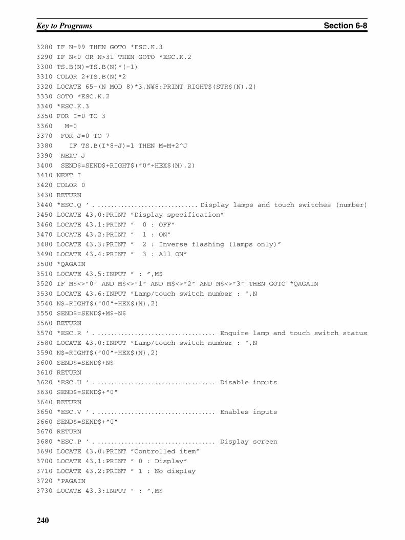
Key to Programs Section 6-8
3280 IF N=99 THEN GOTO *ESC.K.3
3290 IF N<0 OR N>31 THEN GOTO *ESC.K.2
3300 TS.B(N)=TS.B(N)*(–1)
3310 COLOR 2+TS.B(N)*2
3320 LOCATE 65–(N MOD 8)*3,N¥8:PRINT RIGHT$(STR$(N),2)
3330 GOTO *ESC.K.2
3340 *ESC.K.3
3350 FOR I=0 TO 3
3360 M=0
3370 FOR J=0 TO 7
3380 IF TS.B(I*8+J)=1 THEN M=M+2^J
3390 NEXT J
3400 SEND$=SEND$+RIGHT$(”0”+HEX$(M),2)
3410 NEXT I
3420 COLOR 0
3430 RETURN
3440 *ESC.Q ’ Display lamps and touch switches (number). . . . . . . . . . . . . . . . . . . . . . . . . . . . . . .
3450 LOCATE 43,0:PRINT ”Display specification”
3460 LOCATE 43,1:PRINT ” 0 : OFF”
3470 LOCATE 43,2:PRINT ” 1 : ON”
3480 LOCATE 43,3:PRINT ” 2 : Inverse flashing (lamps only)”
3490 LOCATE 43,4:PRINT ” 3 : All ON”
3500 *QAGAIN
3510 LOCATE 43,5:INPUT ” : ”,M$
3520 IF M$<>”0” AND M$<>”1” AND M$<>”2” AND M$<>”3” THEN GOTO *QAGAIN
3530 LOCATE 43,6:INPUT ”Lamp/touch switch number : ”,N
3540 N$=RIGHT$(”00”+HEX$(N),2)
3550 SEND$=SEND$+M$+N$
3560 RETURN
3570 *ESC.R ’ Enquire lamp and touch switch status. . . . . . . . . . . . . . . . . . . . . . . . . . . . . . . . . . . .
3580 LOCATE 43,0:INPUT ”Lamp/touch switch number : ”,N
3590 N$=RIGHT$(”00”+HEX$(N),2)
3600 SEND$=SEND$+N$
3610 RETURN
3620 *ESC.U ’ Disable inputs. . . . . . . . . . . . . . . . . . . . . . . . . . . . . . . . . . . .
3630 SEND$=SEND$+”0”
3640 RETURN
3650 *ESC.V ’ Enables inputs. . . . . . . . . . . . . . . . . . . . . . . . . . . . . . . . . . . .
3660 SEND$=SEND$+”0”
3670 RETURN
3680 *ESC.P ’ Display screen. . . . . . . . . . . . . . . . . . . . . . . . . . . . . . . . . . . .
3690 LOCATE 43,0:PRINT ”Controlled item”
3700 LOCATE 43,1:PRINT ” 0 : Display”
3710 LOCATE 43,2:PRINT ” 1 : No display
3720 *PAGAIN
3730 LOCATE 43,3:INPUT ” : ”,M$
240
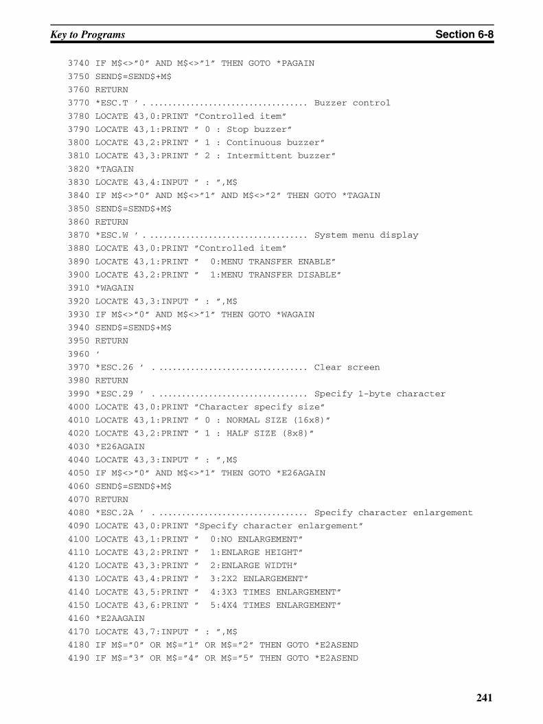
Key to Programs Section 6-8
3740 IF M$<>”0” AND M$<>”1” THEN GOTO *PAGAIN
3750 SEND$=SEND$+M$
3760 RETURN
3770 *ESC.T ’ Buzzer control. . . . . . . . . . . . . . . . . . . . . . . . . . . . . . . . . . . .
3780 LOCATE 43,0:PRINT ”Controlled item”
3790 LOCATE 43,1:PRINT ” 0 : Stop buzzer”
3800 LOCATE 43,2:PRINT ” 1 : Continuous buzzer”
3810 LOCATE 43,3:PRINT ” 2 : Intermittent buzzer”
3820 *TAGAIN
3830 LOCATE 43,4:INPUT ” : ”,M$
3840 IF M$<>”0” AND M$<>”1” AND M$<>”2” THEN GOTO *TAGAIN
3850 SEND$=SEND$+M$
3860 RETURN
3870 *ESC.W ’ System menu display. . . . . . . . . . . . . . . . . . . . . . . . . . . . . . . . . . . .
3880 LOCATE 43,0:PRINT ”Controlled item”
3890 LOCATE 43,1:PRINT ” 0:MENU TRANSFER ENABLE”
3900 LOCATE 43,2:PRINT ” 1:MENU TRANSFER DISABLE”
3910 *WAGAIN
3920 LOCATE 43,3:INPUT ” : ”,M$
3930 IF M$<>”0” AND M$<>”1” THEN GOTO *WAGAIN
3940 SEND$=SEND$+M$
3950 RETURN
3960 ’
3970 *ESC.26 ’ Clear screen. . . . . . . . . . . . . . . . . . . . . . . . . . . . . . . . . .
3980 RETURN
3990 *ESC.29 ’ Specify 1-byte character. . . . . . . . . . . . . . . . . . . . . . . . . . . . . . . . . .
4000 LOCATE 43,0:PRINT ”Character specify size”
4010 LOCATE 43,1:PRINT ” 0 : NORMAL SIZE (16x8)”
4020 LOCATE 43,2:PRINT ” 1 : HALF SIZE (8x8)”
4030 *E26AGAIN
4040 LOCATE 43,3:INPUT ” : ”,M$
4050 IF M$<>”0” AND M$<>”1” THEN GOTO *E26AGAIN
4060 SEND$=SEND$+M$
4070 RETURN
4080 *ESC.2A ’ Specify character enlargement. . . . . . . . . . . . . . . . . . . . . . . . . . . . . . . . . .
4090 LOCATE 43,0:PRINT ”Specify character enlargement”
4100 LOCATE 43,1:PRINT ” 0:NO ENLARGEMENT”
4110 LOCATE 43,2:PRINT ” 1:ENLARGE HEIGHT”
4120 LOCATE 43,3:PRINT ” 2:ENLARGE WIDTH”
4130 LOCATE 43,4:PRINT ” 3:2X2 ENLARGEMENT”
4140 LOCATE 43,5:PRINT ” 4:3X3 TIMES ENLARGEMENT”
4150 LOCATE 43,6:PRINT ” 5:4X4 TIMES ENLARGEMENT”
4160 *E2AAGAIN
4170 LOCATE 43,7:INPUT ” : ”,M$
4180 IF M$=”0” OR M$=”1” OR M$=”2” THEN GOTO *E2ASEND
4190 IF M$=”3” OR M$=”4” OR M$=”5” THEN GOTO *E2ASEND
241

Key to Programs Section 6-8
4200 GOTO *E2AAGAIN
4210 *E2ASEND
4220 SEND$=SEND$+M$
4230 RETURN
4240 *ESC.21 ’ Normal display. . . . . . . . . . . . . . . . . . . . . . . . . . . . . . . . . .
4250 RETURN
4260 *ESC.22 ’ Set inverse display. . . . . . . . . . . . . . . . . . . . . . . . . . . . . . . . . .
4270 RETURN
4280 *ESC.23 ’ End inverse display. . . . . . . . . . . . . . . . . . . . . . . . . . . . . . . . . .
4290 RETURN
4300 *ESC.24 ’ Set flashing display. . . . . . . . . . . . . . . . . . . . . . . . . . . . . . . . . .
4310 RETURN
4320 *ESC.25 ’ End flashing display. . . . . . . . . . . . . . . . . . . . . . . . . . . . . . . . . .
4330 RETURN
4340 *ESC.2B ’ Set cursor position. . . . . . . . . . . . . . . . . . . . . . . . . . . . . . . . . .
4350 *E2B.X
4360 LOCATE 43,0:PRINT SPACE$(36)
4370 LOCATE 43,0:INPUT ”X COORDINATE(000-255)”,BX
4380 IF BX>639 OR BX<0 THEN *E2B.X
4390 *E2B.Y
4400 LOCATE 43,1:PRINT SPACE$(36)
4410 LOCATE 43,1:INPUT ”Y COORDINATE(000–127)”,BY
4420 IF BY>255 OR BY<0 THEN *E2B.Y
4430 BX$=STR$(BX):BX$=RIGHT$(BX$,LEN(BX$)–1):BX$=RIGHT$(”00”+BX$,3)
4440 BY$=STR$(BY):BY$=RIGHT$(BY$,LEN(BY$)–1):BY$=RIGHT$(”00”+BY$,3)
4450 SEND$=SEND$+BX$+BY$
4460 RETURN
4470 *ESC.4 ’ Specify Displayed Characters. . . . . . . . . . . . . . . . . . . . . . . . . . . . . . . . . . . .
4480 LOCATE 43,0:PRINT ”Write character string (32 CHARACTERS MAX.) ––>|”
4490 LOCATE 43,1:INPUT C$
4500 C$=LEFT$(C$,32):L$=RIGHT$(”0”+HEX$(LEN(C$)),2)
4510 SEND$=SEND$+L$+C$
4520 RETURN
4530 *ESC.7 ’ Draw Polyline. . . . . . . . . . . . . . . . . . . . . . . . . . . . . . . . . . . .
4540 LN=0:SL$=””
4550 *E7.X
4560 LOCATE 41,8:PRINT SPACE$(38)
4570 LOCATE 41,9:PRINT SPACE$(38)
4580 LOCATE 41,8:INPUT ”X COORDINATE(END AT 999) : ”,LX
4590 IF LX=999 THEN *E7.E
4600 IF LX<0 OR LX>255 THEN GOTO *E7.X
4610 *E7.Y
4620 LOCATE 41,9:PRINT SPACE$(38)
4630 LOCATE 41,9:INPUT ”Y COORDINATE : ”,LY
4640 IF LY<0 OR LY>127 THEN GOTO *E7.Y
4650 LX$=STR$(LX):LX$=RIGHT$(LX$,LEN(LX$)–1):LX$=RIGHT$(”00”+LX$,3)
242

Key to Programs Section 6-8
4660 LY$=STR$(LY):LY$=RIGHT$(LY$,LEN(LY$)–1):LY$=RIGHT$(”00”+LY$,3)
4670 LOCATE 39+(LN MOD 5)*8,LN¥5:PRINT LX$;”,”;LY$;
4680 SL$=SL$+LX$+LY$
4690 LN=LN+1
4700 IF LN<40 THEN GOTO *E7.X
4710 *E7.E
4720 LN$=HEX$(LN–1):LN$=RIGHT$(”0”+LN$,2)
4730 SEND$=SEND$+LN$+SL$
4740 RETURN
4750 *ESC.8 ’ Draw circle. . . . . . . . . . . . . . . . . . . . . . . . . . . . . . . . . . . .
4760 *E8.X
4770 LOCATE 43,0:PRINT SPACE$(36)
4780 LOCATE 43,0:INPUT ”X COORDINATE OF CENTER OF CIRCLE : ”,CX
4790 IF CX>255 OR CX<0 THEN *E8.X
4800 *E8.Y
4810 LOCATE 43,1:PRINT SPACE$(36)
4820 LOCATE 43,1:INPUT ”Y COORDINATE OF CENTER OF CIRCLE : ”,CY
4830 IF CY>127 OR CY<0 THEN *E8.Y
4840 *E8.R
4850 LOCATE 43,2:PRINT SPACE$(36)
4860 LOCATE 43,2:INPUT ”?????#####”,CR
4870 IF CR>63 OR CR<0 THEN *E8.R
4880 CX$=STR$(CX):CX$=RIGHT$(CX$,LEN(CX$)–1):CX$=RIGHT$(”00”+CX$,3)
4890 CY$=STR$(CY):CY$=RIGHT$(CY$,LEN(CY$)–1):CY$=RIGHT$(”00”+CY$,3)
4900 CR$=STR$(CR):CR$=RIGHT$(CR$,LEN(CR$)–1):CR$=RIGHT$(”00”+CR$,3)
4910 SEND$=SEND$+CX$+CY$+CR$
4920 RETURN
4930 ’
4940 *SELECT ’ Item selection routine. . . . . . . . . . . . . . . . . . . . . . . . . . . . . . . . . .
4950 IF LV=0 THEN LX=3 ELSE LX=LV*20+1
4960 IF LV=0 THEN LY=1 ELSE LY=0
5970 COLOR 4:LOCATE LX,LY:PRINT CMND$(SECT.NO,1,0)
5980 COLOR 0
5990 FOR I=2 TO CMND(SECT.NO)
5000 IF LV=0 AND I<=5 THEN LY=I
5010 IF LV=0 AND I>5 THEN LY=I+1
5020 IF LV=1 THEN LY=I–1
5030 LOCATE LX,LY:PRINT CMND$(SECT.NO,I,0)
5040 NEXT I
5050 *KY.IN
5060 A$=INKEY$:IF A$=”” THEN GOTO *KY.IN
5070 IF A$<>CHR$(&H1B) THEN GOTO *KY1
5080 COLOR 0
5090 FOR I=1 TO CMND(SECT.NO)
5100 IF LV=0 AND I<=5 THEN LY=I
5110 IF LV=0 AND I>5 THEN LY=I+1
243
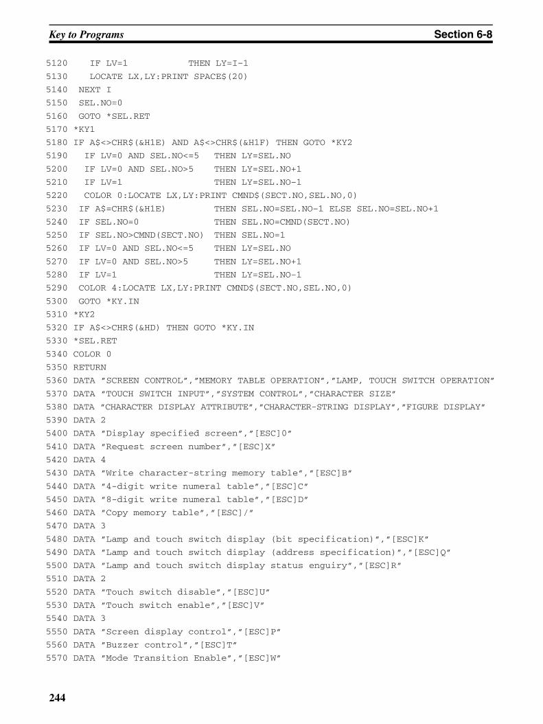
Key to Programs Section 6-8
5120 IF LV=1 THEN LY=I–1
5130 LOCATE LX,LY:PRINT SPACE$(20)
5140 NEXT I
5150 SEL.NO=0
5160 GOTO *SEL.RET
5170 *KY1
5180 IF A$<>CHR$(&H1E) AND A$<>CHR$(&H1F) THEN GOTO *KY2
5190 IF LV=0 AND SEL.NO<=5 THEN LY=SEL.NO
5200 IF LV=0 AND SEL.NO>5 THEN LY=SEL.NO+1
5210 IF LV=1 THEN LY=SEL.NO–1
5220 COLOR 0:LOCATE LX,LY:PRINT CMND$(SECT.NO,SEL.NO,0)
5230 IF A$=CHR$(&H1E) THEN SEL.NO=SEL.NO–1 ELSE SEL.NO=SEL.NO+1
5240 IF SEL.NO=0 THEN SEL.NO=CMND(SECT.NO)
5250 IF SEL.NO>CMND(SECT.NO) THEN SEL.NO=1
5260 IF LV=0 AND SEL.NO<=5 THEN LY=SEL.NO
5270 IF LV=0 AND SEL.NO>5 THEN LY=SEL.NO+1
5280 IF LV=1 THEN LY=SEL.NO–1
5290 COLOR 4:LOCATE LX,LY:PRINT CMND$(SECT.NO,SEL.NO,0)
5300 GOTO *KY.IN
5310 *KY2
5320 IF A$<>CHR$(&HD) THEN GOTO *KY.IN
5330 *SEL.RET
5340 COLOR 0
5350 RETURN
5360 DATA ”SCREEN CONTROL”,”MEMORY TABLE OPERATION”,”LAMP, TOUCH SWITCH OPERATION”
5370 DATA ”TOUCH SWITCH INPUT”,”SYSTEM CONTROL”,”CHARACTER SIZE”
5380 DATA ”CHARACTER DISPLAY ATTRIBUTE”,”CHARACTER-STRING DISPLAY”,”FIGURE DISPLAY”
5390 DATA 2
5400 DATA ”Display specified screen”,”[ESC]0”
5410 DATA ”Request screen number”,”[ESC]X”
5420 DATA 4
5430 DATA ”Write character-string memory table”,”[ESC]B”
5440 DATA ”4-digit write numeral table”,”[ESC]C”
5450 DATA ”8-digit write numeral table”,”[ESC]D”
5460 DATA ”Copy memory table”,”[ESC]/”
5470 DATA 3
5480 DATA ”Lamp and touch switch display (bit specification)”,”[ESC]K”
5490 DATA ”Lamp and touch switch display (address specification)”,”[ESC]Q”
5500 DATA ”Lamp and touch switch display status enguiry”,”[ESC]R”
5510 DATA 2
5520 DATA ”Touch switch disable”,”[ESC]U”
5530 DATA ”Touch switch enable”,”[ESC]V”
5540 DATA 3
5550 DATA ”Screen display control”,”[ESC]P”
5560 DATA ”Buzzer control”,”[ESC]T”
5570 DATA ”Mode Transition Enable”,”[ESC]W”
244
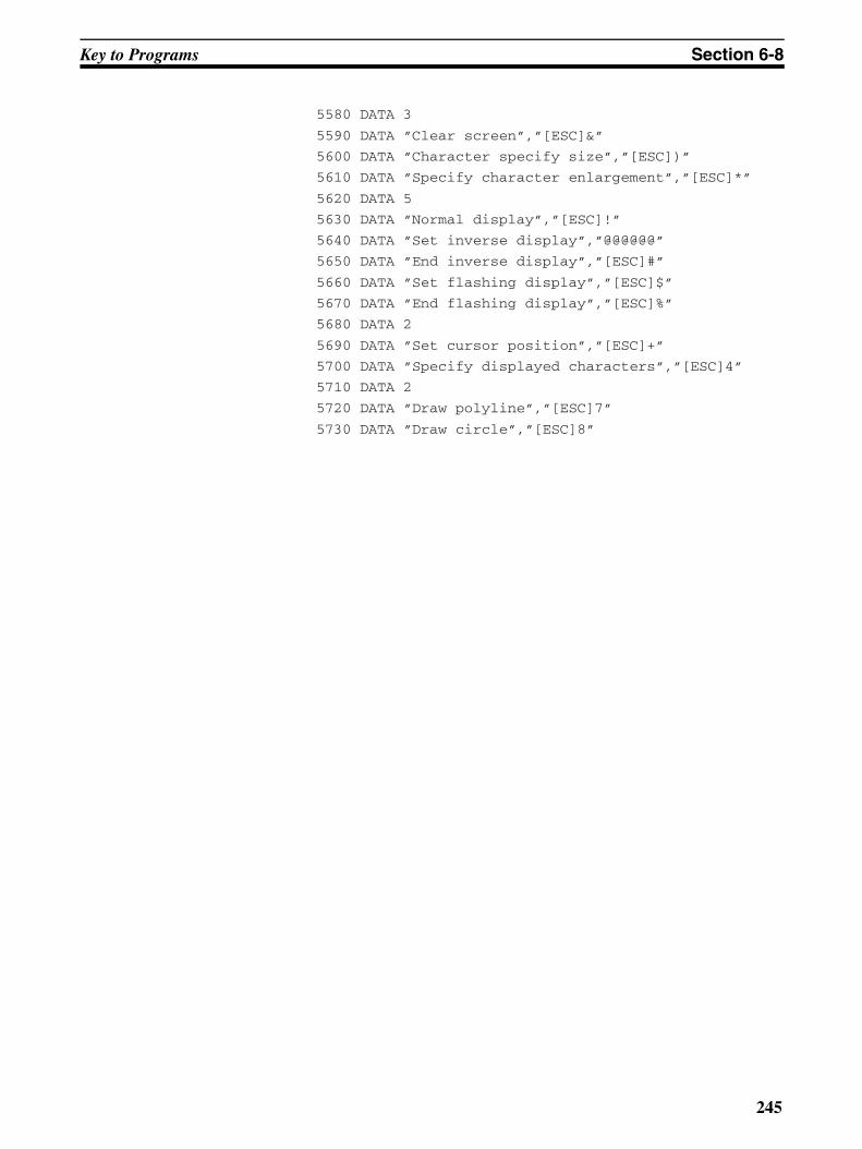
Key to Programs Section 6-8
5580 DATA 3
5590 DATA ”Clear screen”,”[ESC]&”
5600 DATA ”Character specify size”,”[ESC])”
5610 DATA ”Specify character enlargement”,”[ESC]*”
5620 DATA 5
5630 DATA ”Normal display”,”[ESC]!”
5640 DATA ”Set inverse display”,”@@@@@@”
5650 DATA ”End inverse display”,”[ESC]#”
5660 DATA ”Set flashing display”,”[ESC]$”
5670 DATA ”End flashing display”,”[ESC]%”
5680 DATA 2
5690 DATA ”Set cursor position”,”[ESC]+”
5700 DATA ”Specify displayed characters”,”[ESC]4”
5710 DATA 2
5720 DATA ”Draw polyline”,”[ESC]7”
5730 DATA ”Draw circle”,”[ESC]8”
245

Key to Programs Section 6-8
246
SECTION 7Troubleshooting and Maintenance
This section describes the action to take when NT20 errors occur, and how to carry out maintenance and inspections toprevent the occurrence of errors.
7-1 Hardware Faults . . . . . . . . . . . . . . . . . . . . . . . . . . . . . . . . . . . . . . . . . . . . . . . 248
7-2 Responding to Displayed Error Messages . . . . . . . . . . . . . . . . . . . . . . . . . . . 249
7-2-1 Errors Occurring When the Power Is Turned ON . . . . . . . . . . . . . . 249
7-2-2 Errors Occurring during Operation. . . . . . . . . . . . . . . . . . . . . . . . . . 249
7-2-3 Errors Occurring on Screen Data Initialization . . . . . . . . . . . . . . . . 249
7-2-4 Errors Occurring on Resource Transmit Mode. . . . . . . . . . . . . . . . . 250
7-2-5 Errors Occurring on System Program Transmit Mode. . . . . . . . . . . 250
7-2-6 Communications Errors . . . . . . . . . . . . . . . . . . . . . . . . . . . . . . . . . . 251
7-3 Maintenance of the NT20 . . . . . . . . . . . . . . . . . . . . . . . . . . . . . . . . . . . . . . . . 253
7-4 Inspection and Cleaning . . . . . . . . . . . . . . . . . . . . . . . . . . . . . . . . . . . . . . . . . 253
247
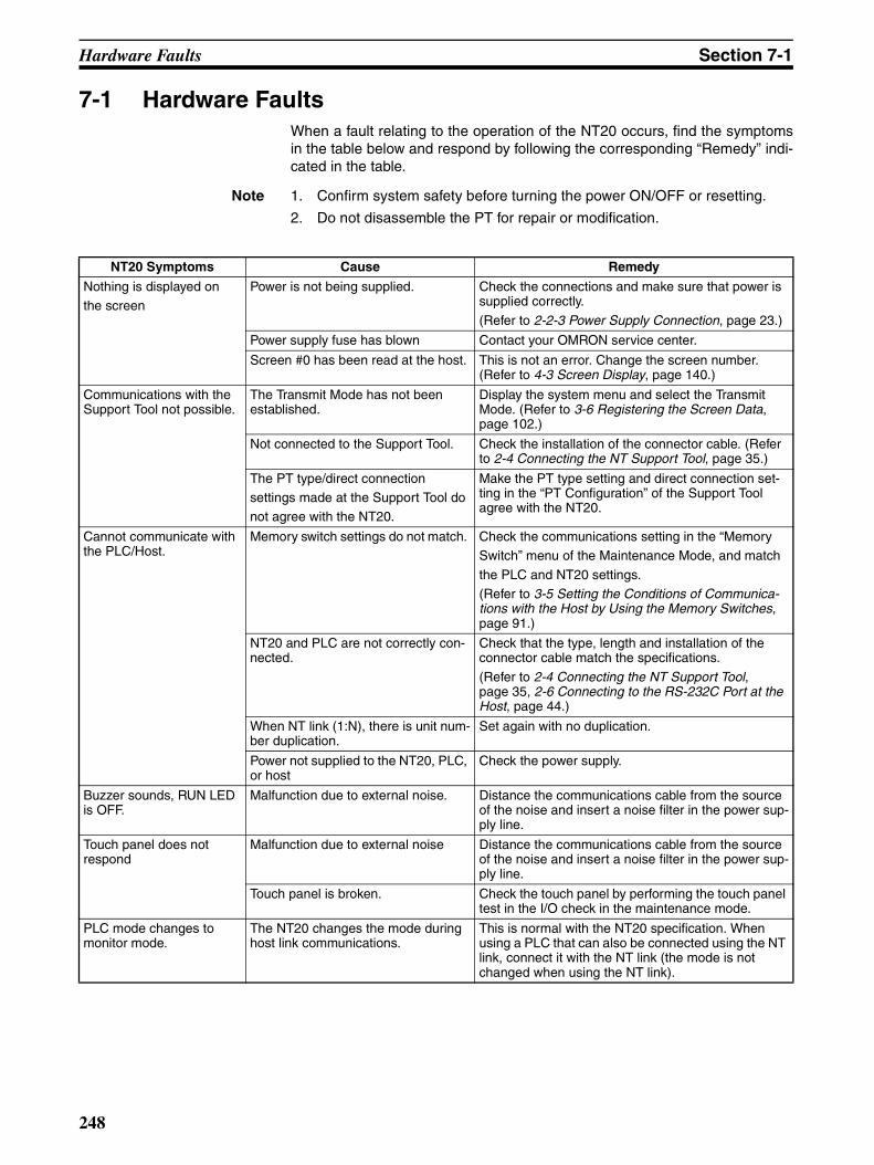
Hardware Faults Section 7-1
7-1 Hardware FaultsWhen a fault relating to the operation of the NT20 occurs, find the symptomsin the table below and respond by following the corresponding “Remedy” indi-cated in the table.
Note 1. Confirm system safety before turning the power ON/OFF or resetting.
2. Do not disassemble the PT for repair or modification.
NT20 Symptoms Cause Remedy
Nothing is displayed onthe screen
Power is not being supplied. Check the connections and make sure that power is supplied correctly.
(Refer to 2-2-3 Power Supply Connection, page 23.)
Power supply fuse has blown Contact your OMRON service center.
Screen #0 has been read at the host. This is not an error. Change the screen number. (Refer to 4-3 Screen Display, page 140.)
Communications with the Support Tool not possible.
The Transmit Mode has not been established.
Display the system menu and select the Transmit Mode. (Refer to 3-6 Registering the Screen Data, page 102.)
Not connected to the Support Tool. Check the installation of the connector cable. (Refer to 2-4 Connecting the NT Support Tool, page 35.)
The PT type/direct connection settings made at the Support Tool do not agree with the NT20.
Make the PT type setting and direct connection set-ting in the “PT Configuration” of the Support Tool agree with the NT20.
Cannot communicate with the PLC/Host.
Memory switch settings do not match. Check the communications setting in the “Memory Switch” menu of the Maintenance Mode, and match
the PLC and NT20 settings. (Refer to 3-5 Setting the Conditions of Communica-tions with the Host by Using the Memory Switches, page 91.)
NT20 and PLC are not correctly con-nected.
Check that the type, length and installation of the connector cable match the specifications.
(Refer to 2-4 Connecting the NT Support Tool, page 35, 2-6 Connecting to the RS-232C Port at the Host, page 44.)
When NT link (1:N), there is unit num-ber duplication.
Set again with no duplication.
Power not supplied to the NT20, PLC, or host
Check the power supply.
Buzzer sounds, RUN LED is OFF.
Malfunction due to external noise. Distance the communications cable from the source of the noise and insert a noise filter in the power sup-ply line.
Touch panel does not respond
Malfunction due to external noise Distance the communications cable from the source of the noise and insert a noise filter in the power sup-ply line.
Touch panel is broken. Check the touch panel by performing the touch panel test in the I/O check in the maintenance mode.
PLC mode changes to monitor mode.
The NT20 changes the mode during host link communications.
This is normal with the NT20 specification. When using a PLC that can also be connected using the NT link, connect it with the NT link (the mode is not changed when using the NT link).
248
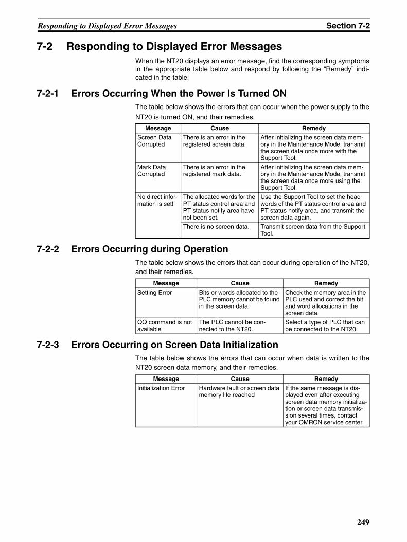
Responding to Displayed Error Messages Section 7-2
7-2 Responding to Displayed Error MessagesWhen the NT20 displays an error message, find the corresponding symptomsin the appropriate table below and respond by following the “Remedy” indi-cated in the table.
7-2-1 Errors Occurring When the Power Is Turned ONThe table below shows the errors that can occur when the power supply to the
NT20 is turned ON, and their remedies.
7-2-2 Errors Occurring during OperationThe table below shows the errors that can occur during operation of the NT20,and their remedies.
7-2-3 Errors Occurring on Screen Data InitializationThe table below shows the errors that can occur when data is written to theNT20 screen data memory, and their remedies.
Message Cause Remedy
Screen Data Corrupted
There is an error in the registered screen data.
After initializing the screen data mem-ory in the Maintenance Mode, transmit the screen data once more with the Support Tool.
Mark Data Corrupted
There is an error in the registered mark data.
After initializing the screen data mem-ory in the Maintenance Mode, transmit the screen data once more using the Support Tool.
No direct infor-mation is set!
The allocated words for the PT status control area and PT status notify area have not been set.
Use the Support Tool to set the head words of the PT status control area and PT status notify area, and transmit the screen data again.
There is no screen data. Transmit screen data from the Support Tool.
Message Cause Remedy
Setting Error Bits or words allocated to the PLC memory cannot be found in the screen data.
Check the memory area in the PLC used and correct the bit and word allocations in the screen data.
QQ command is not available
The PLC cannot be con-nected to the NT20.
Select a type of PLC that can be connected to the NT20.
Message Cause Remedy
Initialization Error Hardware fault or screen data memory life reached
If the same message is dis-played even after executing screen data memory initializa-tion or screen data transmis-sion several times, contact your OMRON service center.
249

Responding to Displayed Error Messages Section 7-2
7-2-4 Errors Occurring on Resource Transmit ModeThe table below shows the errors that can occur when erasing resource,downloading resource or when NT20 is power on, and their remedies.
7-2-5 Errors Occurring on System Program Transmit ModeThe table below shows the errors that can occur when erasing system pro-gram, downloading system program or when NT20 is power on, and their rem-edies.
Message Cause Remedy
Erasing failed. Hardware fault or resource memory life reached
Push the reset switch and erase again. If the same mes-sage is displayed even after executing erase several times, contact your OMRON service center.
Downloading failed. Noise caused data corruption during communications
Push the reset switch and download again. Use noise-resistant cable if communica-tions occurs in an environ-ment with high levels of noise.
Resource Error! Resource is missing or frag-mentary. Checksum of Resource is wrong. There are any two items unmatched among system program, Font Data and System Information Data.
Turn ON the DIP switch 2-5 and push the reset switch to download resource.
Message Cause Remedy
Erasing failed. Hardware fault or resource memory life reached
Push the reset switch and erase again.
Communications Error Time Out
The connectors or the con-necting cable have become disconnected.
Reconnect the cable. Push the reset switch and download again.
System program error!
The power to the NT20 is switched off, or the NT20 is reset, during transfer.The power to the personal computer that is running the system transfer tool is switched off, or the personal computer is reset, during transfer.The cable connecting the per-sonal computer running the system transfer tool and the NT20 becomes disconnected or sustains a wire breakage during transfer.Transfer is terminated by pressing any two of the func-tion keys on the panel of the NT20.Transfer is terminated by pressing the ESC key of the personal computer running the system transfer tool.
Please download system pro-gram again.
250
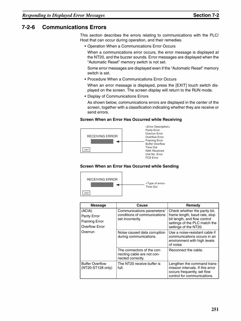
Responding to Displayed Error Messages Section 7-2
7-2-6 Communications ErrorsThis section describes the errors relating to communications with the PLC/Host that can occur during operation, and their remedies.
• Operation When a Communications Error Occurs
When a communications error occurs, the error message is displayed atthe NT20, and the buzzer sounds. Error messages are displayed when the“Automatic Reset” memory switch is not set.
Some error messages are displayed even if the “Automatic Reset” memoryswitch is set.
• Procedure When a Communications Error Occurs
When an error message is displayed, press the [EXIT] touch switch dis-played on the screen. The screen display will return to the RUN mode.
• Display of Communications Errors
As shown below, communications errors are displayed in the center of thescreen, together with a classification indicating whether they are receive orsend errors.
Screen When an Error Has Occurred while Receiving
Screen When an Error Has Occurred while Sending
Message Cause Remedy
(ACIA)Parity Error
Framing ErrorOverflow ErrorOverrun
Communications parameters/conditions of communications set incorrectly.
Check whether the parity bit, frame length, baud rate, stop bit length, and flow control settings of the PLC match the settings of the NT20.
Noise caused data corruption during communications.
Use a noise-resistant cable if communications occurs in an environment with high levels of noise.
The connectors of the con-necting cable are not con-nected correctly.
Reconnect the cable.
Buffer Overflow (NT20-ST128 only)
The NT20 receive buffer is full.
Lengthen the command trans-mission intervals. If this error occurs frequently, set flow control for communications.
RECEIVING ERROR
EXIT
<Error Description> Parity Error Overrun Error Overflow Error Framing Error Buffer Overflow Time Out NAK Received Unit No. ErrorFCS Error
RECEIVING ERROR
EXIT
<Type of error> Time Out
251

Responding to Displayed Error Messages Section 7-2
Time Out The connectors of the con-necting cable have become disconnected.
Reconnect the cable.
The PLC is stopped. Make sure the PLC is able to communicate with the NT20.
During transmission of one command, a time lapse exceeding 5 seconds is detected.
Confirm the proper command length.
Reconnect the cable.
NAK Received (end code simulta-neously displayed)
Noise caused data corruption during communications.
Use a noise-resistant cable if communications occurs in an environment with high levels of noise.
Error returned by host. Check the end code by refer-ring to the PLC operation manual.
Unit No. Error The unit # does not match that set on the PLC.
Set the PLC unit # to “0”.
The PLC is transmitting incor-rect data.
Check PLC operation.
Noise caused data corruption during communications.
Use a noise-resistant cable if communications occurs in an environment with high levels of noise.
FCS Error The PLC is transmitting incor-rect data.
Check PLC operation.
Noise caused data corruption during communications.
Use a noise-resistant cable if communications occurs in an environment with high levels of noise.
Message Cause Remedy
252

Maintenance of the NT20 Section 7-3
7-3 Maintenance of the NT20Carry out maintenance work in order to ensure that the NT20 is always usedin its optimum condition.
!WARNING Do not attempt to take the PLC apart and do not touch any internal parts whilethe power is being supplied. Doing either of these may result in electricalshock.
Spare PT It is advisable to have a spare NT20 available to minimize system downtime inthe event of an NT20 failure or if the screen display becomes difficult to readdue to deterioration of the display unit.
Backlight The backlight must be replaced when the brightness of the display backlightdims and the display becomes difficult to see. The backlight cannot bereplaced by the user.
Contact your nearest OMRON representative.
7-4 Inspection and CleaningClean and inspect the NT20 regularly to ensure that it is always used in itsoptimum condition.
Cleaning Method If the display is dirty the screen is difficult to see. Clean the screen from timeto time as follows.
• In daily cleaning, wipe the display with a soft dry cloth.
• If the soiling cannot be removed with a dry cloth, wet the cloth with water,wring it out well and wipe the display with it.
• If rubber or vinyl products, tape, etc. are left stuck to the display for longperiods they will cause staining. If such items are stuck to the display,remove them during cleaning.
Note Never use volatile solvents such as benzene or thinners, or dusters.
Inspection Method In normal environments, inspect the NT20 at intervals of between 6 monthsand a year. In environments that are extremely hot and humid, or very dustyenvironments, shorten the inspection interval.
• Items Required for Inspection
Prepare the following items before starting the inspection.
• The tools supplied with the NT20
• Screwdrivers (Phillips, flat-head)
• Tester (or digital voltmeter)
• Industrial alcohol
• 100% cotton cloth
• Hygrometer (required in some cases)
• Thermometer (required in some cases)
• Synchroscope (required in some cases)
• Pen-writing oscilloscope (required in some cases)
253

Inspection and Cleaning Section 7-4
• Faulty Display Pixels
Although the LCD panel has been manufactured with extremely high-leveltechnology, there can sometimes be pixels that will not light or that will belit constantly. These are characteristic of LCD panels and are not an indi-cation of a faulty display. Please understand that, although we are con-stantly striving to keep these pixels to a minimum, it is not possible withpresent technology to eliminate them completely.
• Points Inspected
Inspect the following points to determine if there is any divergence from thestated criteria. If there is, either improve the surrounding environment sothat the values fall within the stated range, or adjust the NT20.
Note (1) Do not attempt to disassemble the NT20 for repair or modification.
(2) The disposal of the NT20 may be regulated by national or local authori-ties. Dispose of them according to the laws and regulations of the relevantcountry and local authority.
(3) When replacing the NT20 after discovering a fault during inspections,note the following points:
• Be sure to switch the power OFF before replacement.
• After replacement, check that the new NT20 is not subject to the sameerror.
• If a faulty unit is returned for repairs, write as detailed a description ofthe fault as possible and send this description together with the unit tothe OMRON address indicated on the back cover of this book.
Point Inspected Inspection Details Criterion Inspection Instrument
Power supply voltage Fluctuation in power supply terminal volt-age
Permissible voltage fluc-tuation range (24 VDC −15% +15%)
Tester
Ambient environmen-tal conditions
Ambient temperature (temperature in the operation panel)
0 to 50°C Thermometer
Ambient humidity(humidity in the operation panel)
35% to 85% Hygrometer
Presence/absence of dust Dust must not be settled Visual inspection
Mounting conditions Looseness of mounting brackets etc. To be no looseness Accessory tools
Connector connections of connecting cable To be fully inserted and locked, with no loose-ness
Looseness of screws in external wiring To be no looseness Phillips screwdriver
Conditions of external connecting cables Faults such as incipient disconnections.
Visual inspection
External appearance Peeling of front sheet Front sheet must not show any signs of peel-ing.
Visual inspection
254
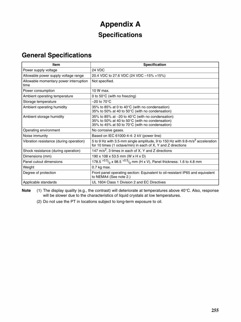
Appendix ASpecifications
General Specifications
Note (1) The display quality (e.g., the contrast) will deteriorate at temperatures above 40°C. Also, responsewill be slower due to the characteristics of liquid crystals at low temperatures.
(2) Do not use the PT in locations subject to long-term exposure to oil.
Item Specification
Power supply voltage 24 VDC
Allowable power supply voltage range 20.4 VDC to 27.6 VDC (24 VDC –15% +15%)
Allowable momentary power interruption time
Not specified.
Power consumption 10 W max.
Ambient operating temperature 0 to 50°C (with no freezing)
Storage temperature –20 to 70°CAmbient operating humidity 35% to 85% at 0 to 40°C (with no condensation)
35% to 50% at 40 to 50°C (with no condensation)
Ambient storage humidity 35% to 85% at −20 to 40°C (with no condensation)35% to 50% at 40 to 50°C (with no condensation)35% to 45% at 50 to 70°C (with no condensation)
Operating environment No corrosive gases.
Noise immunity Based on IEC 61000-4-4: 2 kV (power line)
Vibration resistance (during operation) 5 to 9 Hz with 3.5-mm single amplitude, 9 to 150 Hz with 9.8-m/s2 acceleration for 10 times (1 octave/min) in each of X, Y and Z directions
Shock resistance (during operation) 147 m/s2, 3 times in each of X, Y and Z directions
Dimensions (mm) 190 x 108 x 53.5 mm (W x H x D)
Panel cutout dimensions 178.5 +0.5/0 x 98.5 +0.5/0 mm (H x V), Panel thickness: 1.6 to 4.8 mm
Weight 0.7 kg max.
Degree of protection Front panel operating section: Equivalent to oil-resistant IP65 and equivalent to NEMA4 (See note 2.)
Applicable standards UL 1604 Class 1 Division 2 and EC Directives
255

Specifications Appendix A
Performance Specifications
Display Specifications
Note (1) There are sometimes faulty pixels in the touch panel but this does not indicate an error as long asthe number of bright or dark pixels does not exceed the following limits.
4 total defects max. of the following size with no more than one per 20-mm square:0.2 mm < (short dia. + long dia.)/2 ≤ 0.55 mm
(2) Time taken for brightness to reduce to half at room temperature and humidity. This is a referencevalue only. The life expectancy will be radically reduced at low temperatures. For example, the lifeexpectancy at 0°C or lower will be 10,000 hours (reference value).
Panel Specifications
Item Specification
Display panel (See note 1.)
Display device Monochrome STN LCD (with backlight)
Number of dots(resolution)
140 (128) vertical × 260 (256) horizontal, dot size: 0.42 mmValues in parentheses are the numbers of dots that can be used by the NT20 system program.
Effective display area 66 (57.6) mm vertical × 120 (115.2) mm horizontalValues in parentheses are effective display area that can be used by the NT20 system program.
Display mode Blue mode
View angle Up: 40°, Down: 50°, Left: 35°, Right: 35°Life expectancy 50,000 hours minimum
Contrast adjustment The contrast can be adjusted with the contrast adjustment on the back of NT20.
Backlight(white cold cathode tube)
Life expectancy 50,000 hours minimum (See note 2.)
Replacement User must not replace the backlight.
Brightness adjustment Not provided.
Automatic turn-off Can be set to turn off in 10 minutes, 1 hour, or to remain ON.
Front-panel indicator
RUN Lit green: Running normally and Memory Unit automatic transmission completed.Flashing green: Memory Unit automatic transmission being executed or Memory Unit automatic transmission error.
Item Specification
Touch panel Number of switches: 72 (6 vertically × 12 horizontally)
Switch size: 9.14 mm horizontal × 9.18 mm vertical
Input: Pressure-sensitive type
Life expectancy: 1 million operations min.
256
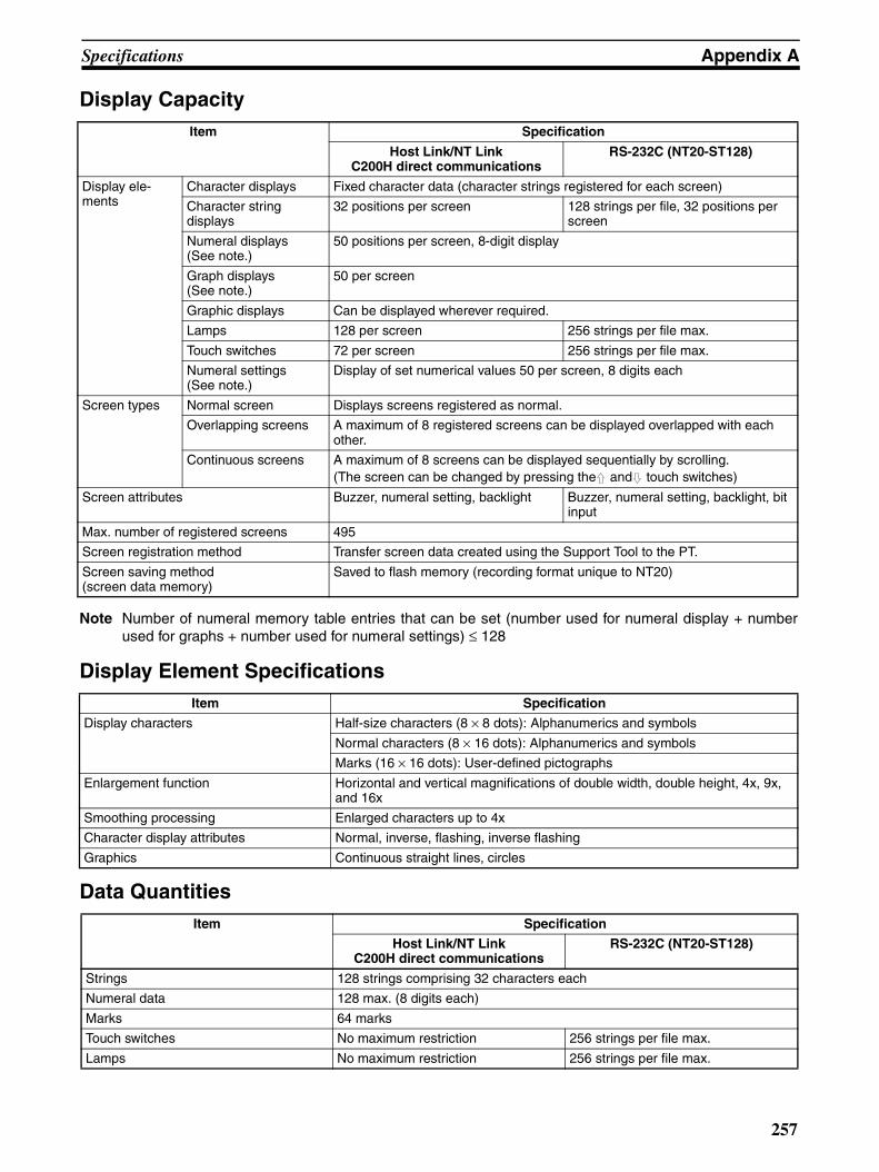
Specifications Appendix A
Display Capacity
Note Number of numeral memory table entries that can be set (number used for numeral display + numberused for graphs + number used for numeral settings) ≤ 128
Display Element Specifications
Data Quantities
Item Specification
Host Link/NT LinkC200H direct communications
RS-232C (NT20-ST128)
Display ele-ments
Character displays Fixed character data (character strings registered for each screen)
Character string displays
32 positions per screen 128 strings per file, 32 positions per screen
Numeral displays (See note.)
50 positions per screen, 8-digit display
Graph displays (See note.)
50 per screen
Graphic displays Can be displayed wherever required.
Lamps 128 per screen 256 strings per file max.
Touch switches 72 per screen 256 strings per file max.
Numeral settings (See note.)
Display of set numerical values 50 per screen, 8 digits each
Screen types Normal screen Displays screens registered as normal.
Overlapping screens A maximum of 8 registered screens can be displayed overlapped with each other.
Continuous screens A maximum of 8 screens can be displayed sequentially by scrolling. (The screen can be changed by pressing the and touch switches)
Screen attributes Buzzer, numeral setting, backlight Buzzer, numeral setting, backlight, bit input
Max. number of registered screens 495
Screen registration method Transfer screen data created using the Support Tool to the PT.
Screen saving method(screen data memory)
Saved to flash memory (recording format unique to NT20)
Item Specification
Display characters Half-size characters (8 × 8 dots): Alphanumerics and symbols
Normal characters (8 × 16 dots): Alphanumerics and symbols
Marks (16 × 16 dots): User-defined pictographs
Enlargement function Horizontal and vertical magnifications of double width, double height, 4x, 9x, and 16x
Smoothing processing Enlarged characters up to 4x
Character display attributes Normal, inverse, flashing, inverse flashing
Graphics Continuous straight lines, circles
Item Specification
Host Link/NT LinkC200H direct communications
RS-232C (NT20-ST128)
Strings 128 strings comprising 32 characters each
Numeral data 128 max. (8 digits each)
Marks 64 marks
Touch switches No maximum restriction 256 strings per file max.
Lamps No maximum restriction 256 strings per file max.
257
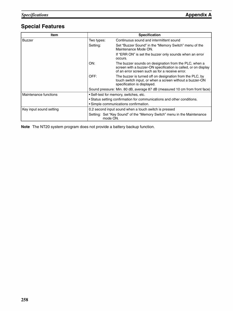
Specifications Appendix A
Special Features
Note The NT20 system program does not provide a battery backup function.
Item Specification
Buzzer Two types: Continuous sound and intermittent soundSetting: Set “Buzzer Sound” in the “Memory Switch” menu of the
Maintenance Mode ON.
If “ERR ON” is set the buzzer only sounds when an error occurs.
ON: The buzzer sounds on designation from the PLC, when a screen with a buzzer-ON specification is called, or on display of an error screen such as for a receive error.
OFF: The buzzer is turned off on designation from the PLC, by touch switch input, or when a screen without a buzzer-ON specification is displayed.
Sound pressure: Min. 80 dB, average 87 dB (measured 10 cm from front face)
Maintenance functions • Self-test for memory, switches, etc.• Status setting confirmation for communications and other conditions.• Simple communications confirmation.
Key input sound setting 0.2 second input sound when a touch switch is pressed
Setting: Set “Key Sound” of the “Memory Switch” menu in the Maintenance mode ON.
258
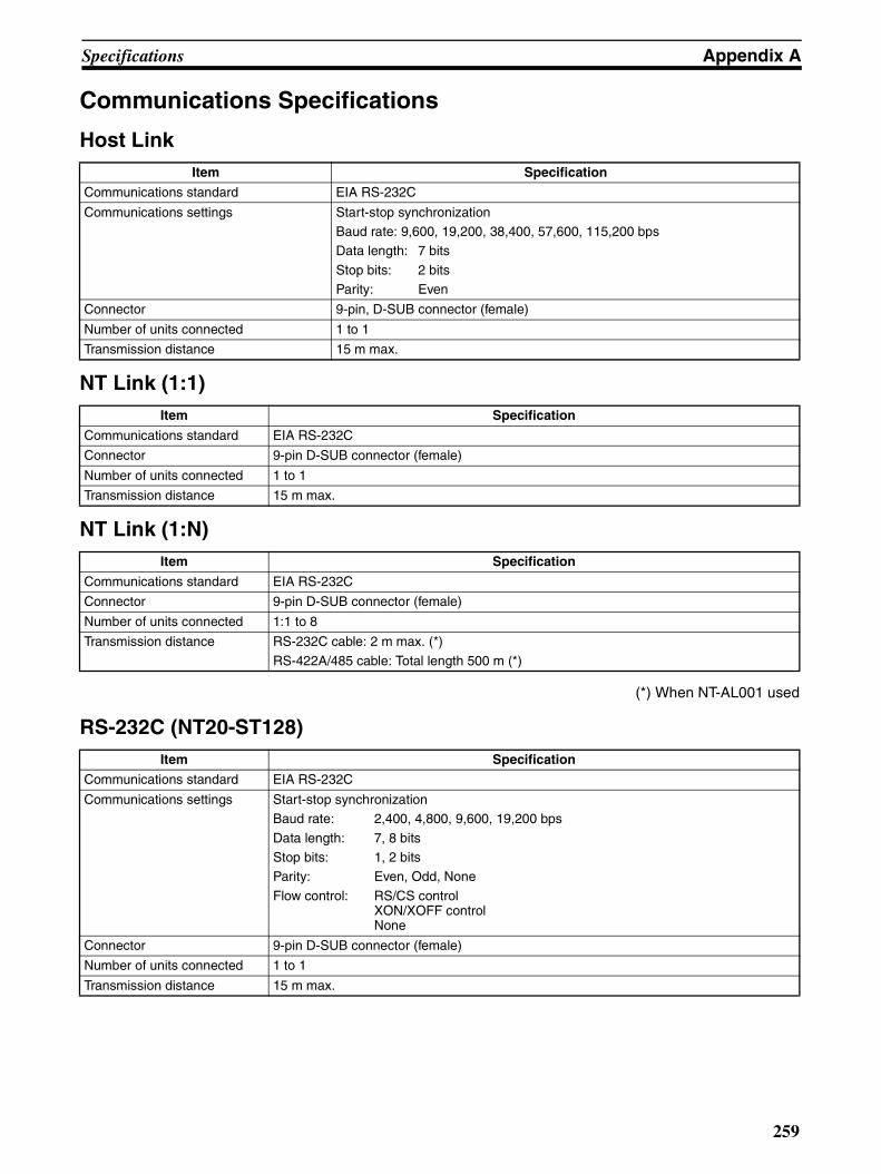
Specifications Appendix A
Communications Specifications
Host Link
NT Link (1:1)
NT Link (1:N)
(*) When NT-AL001 used
RS-232C (NT20-ST128)
Item Specification
Communications standard EIA RS-232C
Communications settings Start-stop synchronizationBaud rate: 9,600, 19,200, 38,400, 57,600, 115,200 bpsData length: 7 bits
Stop bits: 2 bitsParity: Even
Connector 9-pin, D-SUB connector (female)
Number of units connected 1 to 1
Transmission distance 15 m max.
Item Specification
Communications standard EIA RS-232C
Connector 9-pin D-SUB connector (female)
Number of units connected 1 to 1
Transmission distance 15 m max.
Item Specification
Communications standard EIA RS-232C
Connector 9-pin D-SUB connector (female)
Number of units connected 1:1 to 8
Transmission distance RS-232C cable: 2 m max. (*)
RS-422A/485 cable: Total length 500 m (*)
Item Specification
Communications standard EIA RS-232C
Communications settings Start-stop synchronizationBaud rate: 2,400, 4,800, 9,600, 19,200 bps
Data length: 7, 8 bitsStop bits: 1, 2 bitsParity: Even, Odd, None
Flow control: RS/CS controlXON/XOFF controlNone
Connector 9-pin D-SUB connector (female)
Number of units connected 1 to 1
Transmission distance 15 m max.
259

Specifications Appendix A
260

Appendix BDimensions
Outside Dimensions
Installation Dimensions
178.20
190
108
980 −1
4.50
53.50
Unit: mm
Installation panel
Mounting Bracket
178
54
108
RUN
142
16 5 37
190
98
122
Unit: mm
261
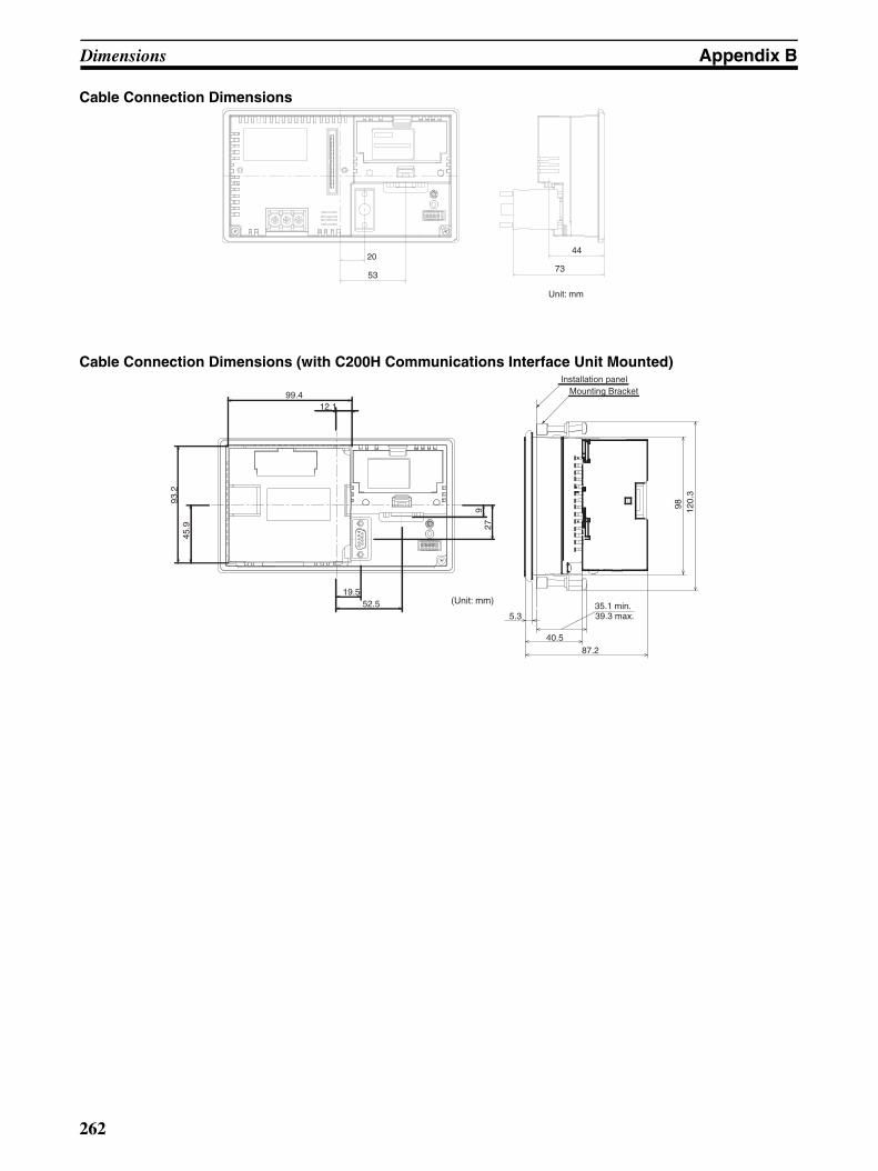
Dimensions Appendix B
Cable Connection Dimensions
Cable Connection Dimensions (with C200H Communications Interface Unit Mounted)
20
53
44
73
Unit: mm
(Unit: mm)
99.412.1
19.552.5
93.2
927
45.9
98 120.
3
35.1 min.5.3
40.587.2
39.3 max.
Installation panelMounting Bracket
262

Appendix CTransporting and Storing PTs
• Use the special packing box provided with the PT when shipping the PT.
• When storing the PT, store it under the following conditions:
Ambient storage temperature: −20 to 70°CAmbient storage humidity: 35% to 85% (−20 to 40°C)
35% to 50% (40 to 50°C)
35% to 45% (50 to 70°C)
263

Transporting and Storing PTs Appendix C
264

Appendix DMaking the Cable
The procedure for making up the cable is described below.
Also refer to this procedure for making a connecting cable for use with RS-422A/485 type connections.
Cable PreparationThe preparation of the cable differs according to whether or not the shielding wire is to be connected to the FG.
Cable with Shield Connected to FG1. Cut the cable to the required length.
2. Remove the external vinyl insulation from the cable with a razor blade. Take care not to damage theshielding underneath.
3. Cut back the shielding wire with scissors.
4. Use wire strippers to strip the insulation from each wire.
5. Fold back the shielding wire.
6. Wrap aluminum foil tape around the folded-back shielding wire.
Cable with Shield Not Connected to FG1. Cut the cable to the required length.
2. Remove the external vinyl insulation from the cable with a razor blade. Take care not to damage theshielding underneath.
3. Cut back the shielding wire with scissors.
4. Use wire strippers to strip the insulation from each wire.
40 (1.57) (RS-232C)25 (0.98) (RS-422A)
10
5
Units: mm (inch) Aluminum foil tape
(1)
(2)
(3)
(4)
(5)
(6)
(0.19)
(0.39)
265

Making the Cable Appendix D
5. Wrap vinyl tape over the cut off end of the shielding wire.
Soldering1. Slide heat-shrink tube over each wire.
2. Pre-solder each wire and connector terminal.
3. Solder each wire to each connector terminal.
4. Push the heat shrink tube over the soldered joint and heat the tube to shrink it in place.
Hood AssemblyAssemble the connector hood as shown below.
40 (1.57) (RS-232C)
5
25 (0.98) (RS-422A)
(1)
(2)
(3)
(4)
(5)
Units: mm (inch) Vinyl tape
(0.19)
Soldering iron
Heat-shrink tube(F, 1.5 mm dia., l = 10 mm)
1 mm
Heat-shrink tube
Aluminum foil tape
End connected to FG End not connected to FG
266
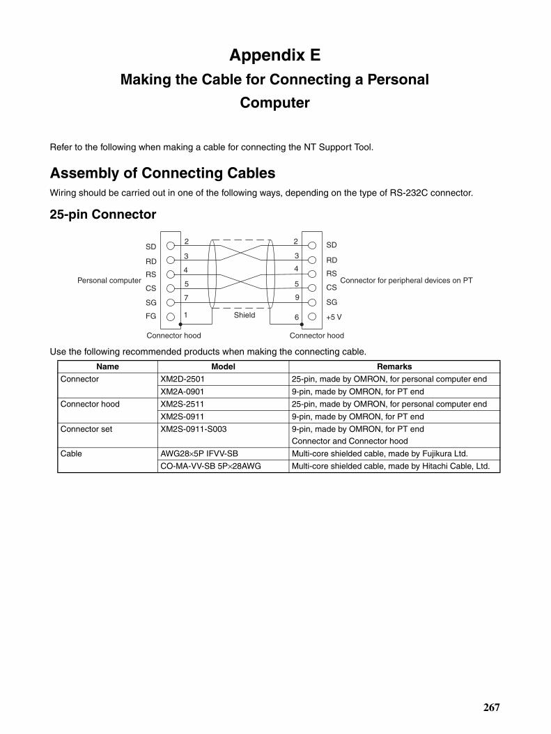
Appendix EMaking the Cable for Connecting a Personal
Computer
Refer to the following when making a cable for connecting the NT Support Tool.
Assembly of Connecting CablesWiring should be carried out in one of the following ways, depending on the type of RS-232C connector.
25-pin Connector
Use the following recommended products when making the connecting cable.
SD
RD
RS
CS
SG
FG
Personal computer Connector for peripheral devices on PT
Shield
Connector hood
2
3
4
5
7
1
SD
RD
RS
CS
SG
+5 V
2
3
4
5
9
6
Connector hood
Name Model Remarks
Connector XM2D-2501 25-pin, made by OMRON, for personal computer end
XM2A-0901 9-pin, made by OMRON, for PT end
Connector hood XM2S-2511 25-pin, made by OMRON, for personal computer end
XM2S-0911 9-pin, made by OMRON, for PT end
Connector set XM2S-0911-S003 9-pin, made by OMRON, for PT endConnector and Connector hood
Cable AWG28×5P IFVV-SB Multi-core shielded cable, made by Fujikura Ltd.
CO-MA-VV-SB 5P×28AWG Multi-core shielded cable, made by Hitachi Cable, Ltd.
267

Making the Cable for Connecting a Personal Computer Appendix E
9-pin Connector
Use the following recommended products when making the connecting cable.
Note One XM2S-0911 (for PT) and either one XM2S-0911 or -0913 (for your personal computer) are needed.
RD
SD
RS
CS
SG
Personal computer Connector for peripheral devices on PT
Shield
Connector hood
2
3
7
8
5
SD
RD
RS
CS
SG
+5 V
2
3
4
5
9
6Connector hood
Name Model Remarks
Connector XM2D-0901 9-pin, made by OMRON, for personal computer
XM2A-0901 9-pin, made by OMRON, for PT
Connector hood (See note.)
XM2S-0911 9-pin, mm pitch screw, made by OMRON
XM2S-0913 9-pin, inch pitch screw, made by OMRON
Connector set XM2S-0911-S003 9-pin, made by OMRON, for PT endConnector and Connector hood
Cable AWG28×5P IFVV-SB Multi-core shielded cable, made by Fujikura Ltd.
CO-MA-VV-SB 5P×28AWG Multi-core shielded cable, made by Hitachi Cable, Ltd.
268
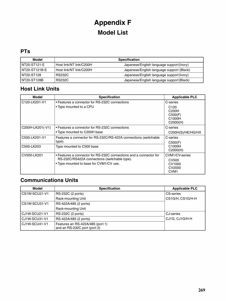
Appendix FModel List
PTs
Host Link Units
Communications Units
Model Specification
NT20-ST121-E Host link/NT link/C200H Japanese/English language support (Ivory)
NT20-ST121B-E Host link/NT link/C200H Japanese/English language support (Black)
NT20-ST128 RS232C Japanese/English language support (Ivory)
NT20-ST128B RS232C Japanese/English language support (Black)
Model Specification Applicable PLC
C120-LK201-V1 • Features a connector for RS-232C connections • Type mounted to a CPU
C-series
C120 C200H C500(F) C1000H C2000(H)
C200H-LK201(-V1) • Features a connector for RS-232C connections • Type mounted to C200H base
C-series C200H(S)/HE/HG/HX
C500-LK201-V1 Features a connector for RS-232C/RS-422A connections (switchable type).
C-series
C500(F) C1000H C2000(H)
C500-LK203 Type mounted to C500 base
CV500-LK201 • Features a connector for RS-232C connections and a connector for RS-232C/RS422A connections (switchable type).
• Type mounted to base for CVM1/CV use.
CVM1/CV-series CV500 CV1000 CV2000 CVM1
Model Specification Applicable PLC
CS1W-SCU21-V1 RS-232C (2 ports)Rack-mounting Unit
CS-seriesCS1G/H, CS1G/H-H
CS1W-SCU31-V1 RS-422A/485 (2 ports)
Rack-mounting Unit
CJ1W-SCU21-V1 RS-232C (2 ports) CJ-series
CJ1G, CJ1G/H-HCJ1W-SCU31-V1 RS-422A/485 (2 ports)
CJ1W-SCU41-V1 Features an RS-422A/485 (port 1) and an RS-232C port (port 2)
269

Model List Appendix F
CPU Units (for Connection Via a Host Link)Model Specification PLC Type
C20H/C28H/C40H/C60H Features a 9-pin connector for RS-232C connections C-series C20HC28H
C40H C60H
CPM1-10CDR-@ CPM1-20CDR-@CPM1-30CDR-@
CPM1A-10CDR@-@CPM1A-30CDR@-@CPM1A-40CDR@-@
Connect an RS-232C adapter to the peripheral port. C-series CPM1CPM1A
CPM2A-30CD@@-@CPM2A-40CD@@-@CPM2A-60CD@@-@
Connect an RS-232C adapter to the peripheral port. C-series CPM2A
CPM2C-10@@@@@@-@ (See note 1.)CPM2C-20@@@@@@-@ (See note 1.)
Connect an RS-232C adapter to the peripheral port. C-series CPM2C
CQM1-CPU21-E CQM1-CPU41-E CQM1-CPU42-E
CQM1-CPU43-E CQM1-CPU44-E
Features a 9-pin connector for RS-232C connections. C-series CQM1
CQM1H-CPU11 (See note 2.) Connect an RS-232C adapter to the peripheral port. C-series CQM1H CQM1H-CPU21
CQM1H-CPU51CQM1H-CPU61
Features a 9-pin connector for RS-232C connections.
C200HS-CPU21-E
C200HS-CPU23-E C200HS-CPU31-E C200HS-CPU33-E
Features a connector for RS-232C connections (select-able/9-pin).
C200HS
C200HE-CPU32-(Z)E (*)
C200HE-CPU42-(Z)E
Features a connector for RS-232C connections (select-able/9-pin)
C-series C200HE
C200HG-CPU33-(Z)E (*)
C200HG-CPU43-(Z)E
C200HG-CPU53-(Z)E (*)
C200HG-CPU63-(Z)E
Features a connector for RS-232C connections (select-able/9-pin).
C-series C200HG
C200HX-CPU34-(Z)E (*)
C200HX-CPU44-(Z)E
C200HX-CPU54-(Z)E (*)
C200HX-CPU64-(Z)E C200HX-CPU65-(Z)E
C200HX-CPU85-(Z)E
Features a connector for RS-232C connections (select-able/9-pin).
C-series
C200HX
CV500-CPU01-EV1 CV1000-CPU01-EV1
CV2000-CPU01-EV1 CVM1-CPU01-EV1 CVM1-CPU11-EV1
CVM1-CPU21-EV1
Features a connector for RS-232C connections (select-able/9-pin).
CVM1/CV-series CV500
CV1000CV2000 CVM1
270

Model List Appendix F
Note For CPU units marked (*), a communications board is required.
1.Use a CPM2C-CN111 or CS1W-CN114/118 Connecting Cable, CPM1-CIF01 RS-232C Adapter, orCPM1-CIF11 RS-422A Adapter to connect.
2.The CQM1H-CPU11 does not have a built-in RS-232C port, so connect to the PT at the peripheral portwith a CS1W-CN118 Connecting Cable.
CS1G-CPU42-EV1CS1G-CPU43-E1
CS1G-CPU44-EVCS1G-CPU45-EV
Features a connector for RS-232C connections. CS-seriesCS1G
CS1H-CPU63-EV1CS1H-CPU64-EV1CS1H-CPU65-EV1
CS1H-CPU66-EV1CS1H-CPU67-EV1
Features a connector for RS-232C connections. CS-seriesCS1H
CS1G-CPU42H
CS1G-CPU43HCS1G-CPU44HCS1G-CPU45H
Features a connector for RS-232C connections. CS-series
CS1G-H
CS1H-CPU63HCS1H-CPU64H
CS1H-CPU65HCS1H-CPU66HCS1H-CPU67H
Features a connector for RS-232C connections. CS-seriesCS1H-H
CJ1G-CPU44CJ1G-CPU45
Features a connector for RS-232C connections. CS-seriesCJ1G
Model Specification PLC Type
271
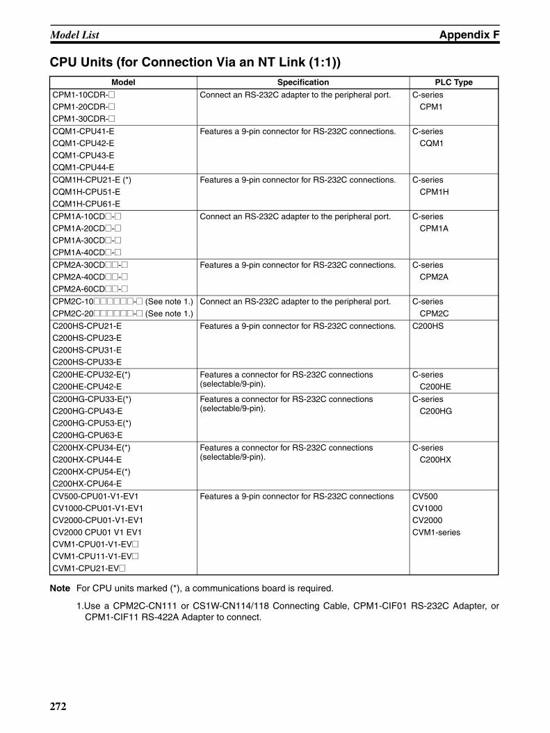
Model List Appendix F
CPU Units (for Connection Via an NT Link (1:1))
Note For CPU units marked (*), a communications board is required.
1.Use a CPM2C-CN111 or CS1W-CN114/118 Connecting Cable, CPM1-CIF01 RS-232C Adapter, orCPM1-CIF11 RS-422A Adapter to connect.
Model Specification PLC Type
CPM1-10CDR-@ CPM1-20CDR-@ CPM1-30CDR-@
Connect an RS-232C adapter to the peripheral port. C-series CPM1
CQM1-CPU41-E CQM1-CPU42-E
CQM1-CPU43-E CQM1-CPU44-E
Features a 9-pin connector for RS-232C connections. C-series CQM1
CQM1H-CPU21-E (*)
CQM1H-CPU51-E CQM1H-CPU61-E
Features a 9-pin connector for RS-232C connections. C-series
CPM1H
CPM1A-10CD@-@ CPM1A-20CD@-@ CPM1A-30CD@-@
CPM1A-40CD@-@
Connect an RS-232C adapter to the peripheral port. C-series CPM1A
CPM2A-30CD@@-@ CPM2A-40CD@@-@
CPM2A-60CD@@-@
Features a 9-pin connector for RS-232C connections. C-series CPM2A
CPM2C-10@@@@@@-@ (See note 1.)
CPM2C-20@@@@@@-@ (See note 1.)
Connect an RS-232C adapter to the peripheral port. C-series
CPM2C
C200HS-CPU21-E C200HS-CPU23-E
C200HS-CPU31-E C200HS-CPU33-E
Features a 9-pin connector for RS-232C connections. C200HS
C200HE-CPU32-E(*) C200HE-CPU42-E
Features a connector for RS-232C connections (selectable/9-pin).
C-series C200HE
C200HG-CPU33-E(*) C200HG-CPU43-E C200HG-CPU53-E(*)
C200HG-CPU63-E
Features a connector for RS-232C connections (selectable/9-pin).
C-series C200HG
C200HX-CPU34-E(*) C200HX-CPU44-E
C200HX-CPU54-E(*) C200HX-CPU64-E
Features a connector for RS-232C connections (selectable/9-pin).
C-series C200HX
CV500-CPU01-V1-EV1 CV1000-CPU01-V1-EV1 CV2000-CPU01-V1-EV1
CV2000 CPU01 V1 EV1 CVM1-CPU01-V1-EV@ CVM1-CPU11-V1-EV@
CVM1-CPU21-EV@
Features a 9-pin connector for RS-232C connections CV500CV1000CV2000
CVM1-series
272
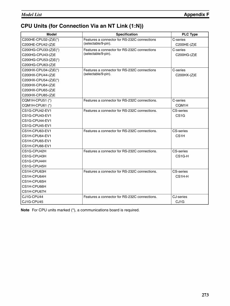
Model List Appendix F
CPU Units (for Connection Via an NT Link (1:N))
Note For CPU units marked (*), a communications board is required.
Model Specification PLC Type
C200HE-CPU32-(Z)E(*) C200HE-CPU42-(Z)E
Features a connector for RS-232C connections (selectable/9-pin).
C-series C200HE-(Z)E
C200HG-CPU33-(Z)E(*) C200HG-CPU43-(Z)E C200HG-CPU53-(Z)E(*)
C200HG-CPU63-(Z)E
Features a connector for RS-232C connections (selectable/9-pin).
C-series C200HG-(Z)E
C200HX-CPU34-(Z)E(*) C200HX-CPU44-(Z)E
C200HX-CPU54-(Z)E(*) C200HX-CPU64-(Z)EC200HX-CPU65-(Z)E
C200HX-CPU85-(Z)E
Features a connector for RS-232C connections (selectable/9-pin).
C-series C200HX-(Z)E
CQM1H-CPU51 (*)
CQM1H-CPU61 (*)
Features a connector for RS-232C connections. C-series
CQM1H
CS1G-CPU42-EV1CS1G-CPU43-EV1
CS1G-CPU44-EV1CS1G-CPU45-EV1
Features a connector for RS-232C connections. CS-series CS1G
CS1H-CPU63-EV1CS1H-CPU64-EV1CS1H-CPU65-EV1
CS1H-CPU66-EV1
Features a connector for RS-232C connections. CS-series CS1H
CS1G-CPU42H
CS1G-CPU43HCS1G-CPU44HCS1G-CPU45H
Features a connector for RS-232C connections. CS-series
CS1G-H
CS1H-CPU63HCS1H-CPU64HCS1H-CPU65H
CS1H-CPU66HCS1H-CPU67H
Features a connector for RS-232C connections. CS-series CS1H-H
CJ1G-CPU44CJ1G-CPU45
Features a connector for RS-232C connections. CJ-series CJ1G
273
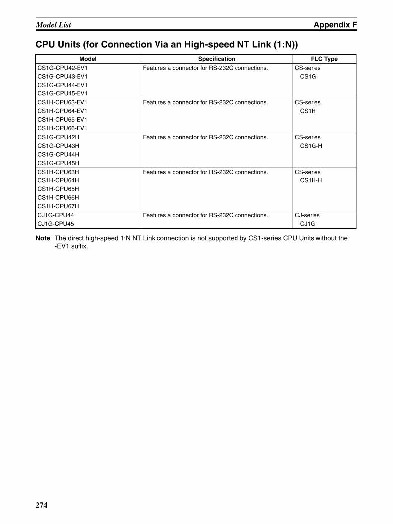
Model List Appendix F
CPU Units (for Connection Via an High-speed NT Link (1:N))
Note The direct high-speed 1:N NT Link connection is not supported by CS1-series CPU Units without the -EV1 suffix.
Model Specification PLC Type
CS1G-CPU42-EV1CS1G-CPU43-EV1CS1G-CPU44-EV1
CS1G-CPU45-EV1
Features a connector for RS-232C connections. CS-series CS1G
CS1H-CPU63-EV1
CS1H-CPU64-EV1CS1H-CPU65-EV1CS1H-CPU66-EV1
Features a connector for RS-232C connections. CS-series
CS1H
CS1G-CPU42HCS1G-CPU43HCS1G-CPU44H
CS1G-CPU45H
Features a connector for RS-232C connections. CS-series CS1G-H
CS1H-CPU63H
CS1H-CPU64HCS1H-CPU65HCS1H-CPU66H
CS1H-CPU67H
Features a connector for RS-232C connections. CS-series
CS1H-H
CJ1G-CPU44CJ1G-CPU45
Features a connector for RS-232C connections. CJ-series CJ1G
274
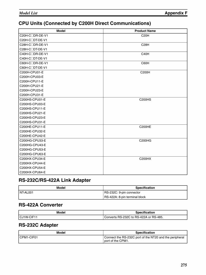
Model List Appendix F
CPU Units (Connected by C200H Direct Communications)
RS-232C/RS-422A Link Adapter
RS-422A Converter
RS-232C Adapter
Model Product Name
C20H-C@DR-DE-V1C20H-C@DT-DE-V1
C20H
C28H-C@DR-DE-V1C28H-C@DT-DE-V1
C28H
C40H-C@DR-DE-V1
C40H-C@DT-DE-V1
C40H
C60H-C@DR-DE-V1
C60H-C@DT-DE-V1
C60H
C200H-CPU01-EC200H-CPU03-E
C200H-CPU11-EC200H-CPU21-EC200H-CPU23-E
C200H-CPU31-E
C200H
C200HS-CPU01-E
C200HS-CPU03-EC200HS-CPU11-EC200HS-CPU21-E
C200HS-CPU23-EC200HS-CPU31-E
C200HS
C200HE-CPU11-E
C200HE-CPU32-EC200HE-CPU42-E
C200HE
C200HG-CPU33-EC200HG-CPU43-EC200HG-CPU53-E
C200HG-CPU63-E
C200HG
C200HX-CPU34-E
C200HX-CPU44-EC200HX-CPU54-EC200HX-CPU64-E
C200HX
Model Specification
NT-AL001 RS-232C: 9-pin connectorRS-422A: 8-pin terminal block
Model Specification
CJ1W-CIF11 Converts RS-232C to RS-422A or RS-485.
Model Specification
CPM1-CIF01 Connect the RS-232C port of the NT20 and the peripheral port of the CPM1.
275

Model List Appendix F
Related Products
Parts Used for Connection
Cables with Connectors
Connecting Cables (for Host Link, NT Link, and RS-232C)
Applicable Connectors (for Host Link, NT Link, and RS-232C)
Name Model Remarks
Support Tool NT-ZJCAT1-EV4 For IBM PC/AT compatible, media: CD-ROM
Options NT20S-KBA04 Reflection-suppressing protective sheet for NT20
NT20S-KBA01 Chemical-resistant cover to NT20
NT-MF261 Memory Unit for NT20
Model Cable Length Applicable Units Communications Method
XW2Z-200S 2 m Host link units with 25-pin
connectors
Host link
XW2Z-500S 5 m
XW2Z-200T 2 m Host link units and CPU units with 9-pin connectors
Host link,
NT link (1 to 1)XW2Z-500T 5 m
C200H-CN311 30 cm C200H, C200HS,C200HX/HG/HE
C200H direct communications
NT20M-CNP711C200H-CN711
70 cm
NT20M-CNP221C200H-CN221
2 m
NT20M-CNP521C200H-CN521
5 m
NT20M-CNP131C200H-CN131
10 m
C200H-CN312 30 cm C@@H
NT20M-CNP712C200H-CN712
70 cm
NT20M-CNP222C200H-CN222
2 m
Model Specification
AWG28×5PIFVV-SB
Multiconductor shielded cable (FUJIKURA, Ltd.)
CO-MA-VV-SB
5P×28AWG
Multiconductor shielded cable (HITACHI Cable, Ltd.)
Name Model Remarks
Connector XM2A-2501 25-pin, manufactured by OMRON
XM2A-0901 9-pin (Plug), manufactured by OMRON
DB-25P 25-pin, manufactured by JAE
Connector cover XM2S-2511 25-pin, manufactured by OMRON
XM2S-0911 9-pin, manufactured by OMRON
DB-C2-J9 25-pin, manufactured by JAE
276
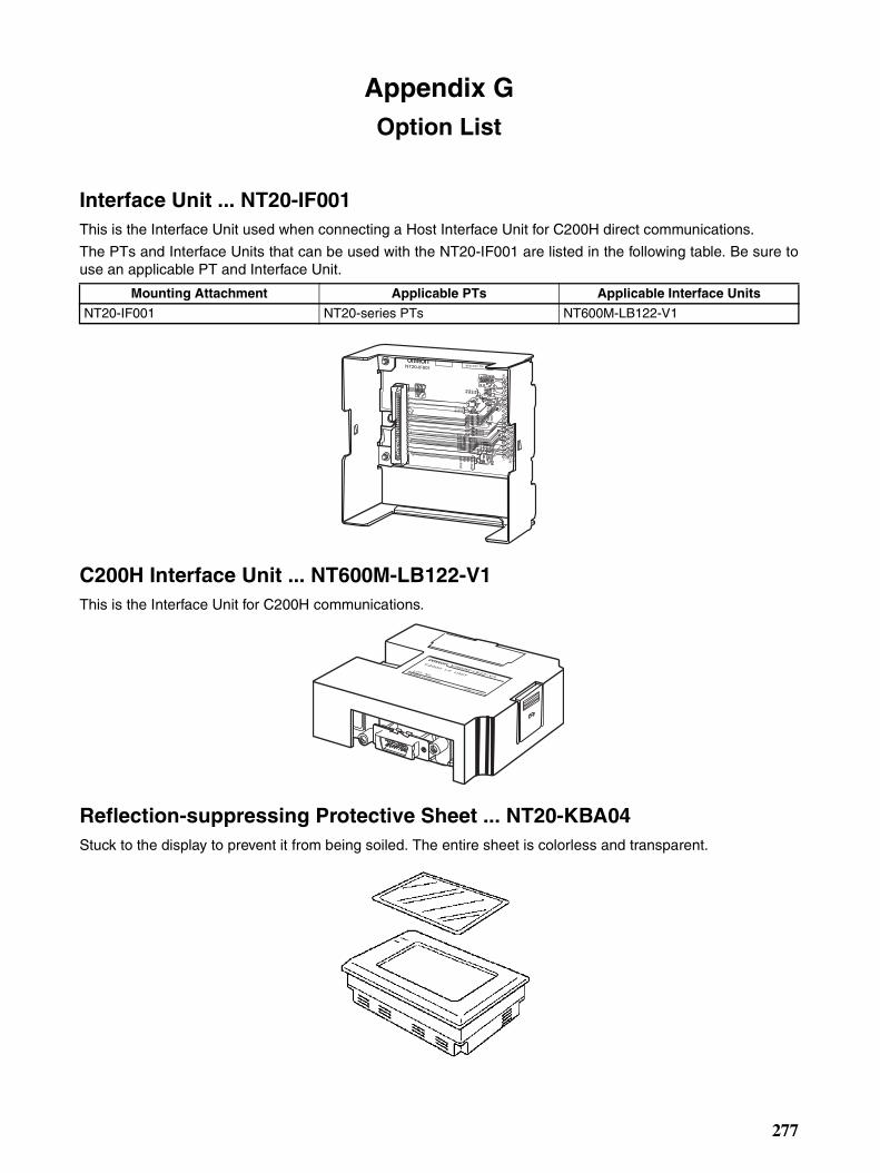
Appendix GOption List
Interface Unit ... NT20-IF001This is the Interface Unit used when connecting a Host Interface Unit for C200H direct communications.
The PTs and Interface Units that can be used with the NT20-IF001 are listed in the following table. Be sure touse an applicable PT and Interface Unit.
C200H Interface Unit ... NT600M-LB122-V1This is the Interface Unit for C200H communications.
Reflection-suppressing Protective Sheet ... NT20-KBA04Stuck to the display to prevent it from being soiled. The entire sheet is colorless and transparent.
Mounting Attachment Applicable PTs Applicable Interface Units
NT20-IF001 NT20-series PTs NT600M-LB122-V1
277

Option List Appendix G
Chemical-resistant Cover (NT20-KBA01)Covers the front panel and protects it from chemical agents. The entire sheet is milky white and made of sili-cone rubber.
The protection the cover affords is summarized below.
For information on protection against chemical agents not included in the table above, please ask OMRON. (Ifit is a chemical agent to which silicone rubber is recognized to be resistant, the cover can be used with confi-dence even if that chemical agent is not listed in the “Protects Against” column above.
Note (1) This cover does not afford protection against all chemical agents.
(2) Since the cover is milky white, it reduces the clarity of the display a little.
(3) This cover is intended to be affixed to the display in order to provide protection against chemicalagents. It will not provide protection against chemical agents that enter through the installation panelor through the gap between the cover and the display.
Memory Unit (NT-MF261)This is a special unit for reading/writing the screen data and the system programs in an NT20. Data is transmit-ted by DIP switch setting at the Memory Unit.
Protects Against Does Not Protect Against
Boric acidSulfuric acid
Nitric acidAmmonia gasCarbon dioxide
PhenolGlycerin
Ammonia waterCalcium chlorideDeveloping fluid (“hypo”)
AcetaldehydeLard
HexaneLubricating oils
BenzeneButaneCarbonic acid
Chlorinated solventsNapthalene
Soya oilToluene
278
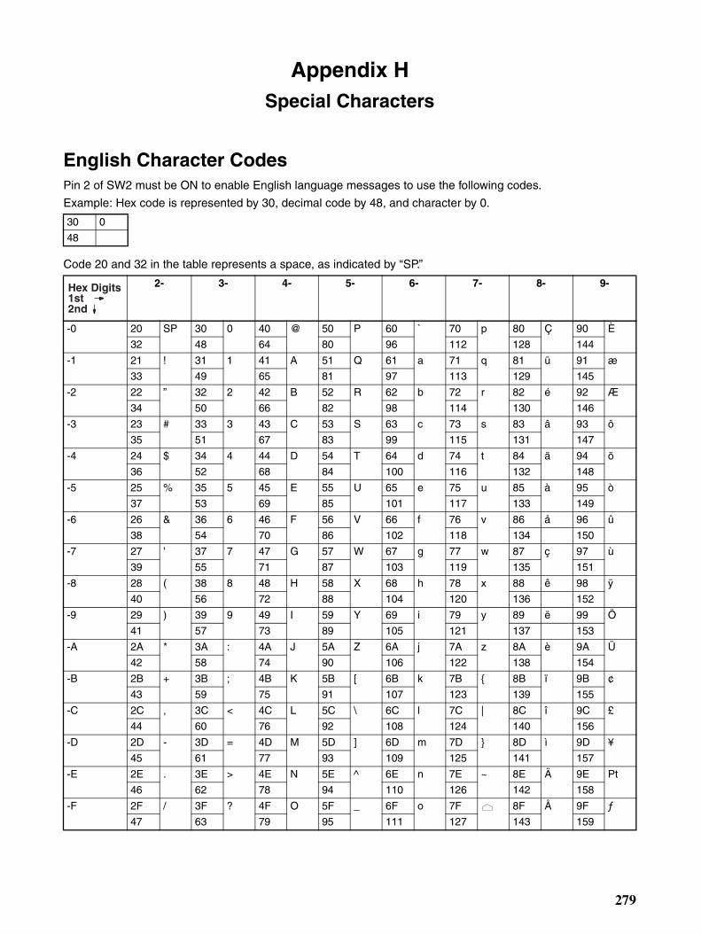
Appendix HSpecial Characters
English Character CodesPin 2 of SW2 must be ON to enable English language messages to use the following codes.
Example: Hex code is represented by 30, decimal code by 48, and character by 0.
Code 20 and 32 in the table represents a space, as indicated by “SP.”
30 0
48
2- 3- 4- 5- 6- 7- 8- 9-
-0 20 SP 30 0 40 @ 50 P 60 ` 70 p 80 Ç 90 È
32 48 64 80 96 112 128 144
-1 21 ! 31 1 41 A 51 Q 61 a 71 q 81 ü 91 æ
33 49 65 81 97 113 129 145
-2 22 ” 32 2 42 B 52 R 62 b 72 r 82 é 92 Æ
34 50 66 82 98 114 130 146
-3 23 # 33 3 43 C 53 S 63 c 73 s 83 â 93 ô
35 51 67 83 99 115 131 147
-4 24 $ 34 4 44 D 54 T 64 d 74 t 84 ä 94 ö
36 52 68 84 100 116 132 148
-5 25 % 35 5 45 E 55 U 65 e 75 u 85 à 95 ò
37 53 69 85 101 117 133 149
-6 26 & 36 6 46 F 56 V 66 f 76 v 86 å 96 û
38 54 70 86 102 118 134 150
-7 27 ’ 37 7 47 G 57 W 67 g 77 w 87 ç 97 ù
39 55 71 87 103 119 135 151
-8 28 ( 38 8 48 H 58 X 68 h 78 x 88 ê 98 ÿ
40 56 72 88 104 120 136 152
-9 29 ) 39 9 49 I 59 Y 69 i 79 y 89 ë 99 Ö
41 57 73 89 105 121 137 153
-A 2A * 3A : 4A J 5A Z 6A j 7A z 8A è 9A Ü
42 58 74 90 106 122 138 154
-B 2B + 3B ; 4B K 5B [ 6B k 7B 8B ï 9B ¢
43 59 75 91 107 123 139 155
-C 2C , 3C < 4C L 5C \ 6C l 7C | 8C î 9C £
44 60 76 92 108 124 140 156
-D 2D - 3D = 4D M 5D ] 6D m 7D 8D ì 9D ¥
45 61 77 93 109 125 141 157
-E 2E . 3E > 4E N 5E ^ 6E n 7E ~ 8E Ä 9E Pt
46 62 78 94 110 126 142 158
-F 2F / 3F ? 4F O 5F _ 6F o 7F 8F Å 9F ƒ
47 63 79 95 111 127 143 159
Hex Digits1st2nd
279

Special Characters Appendix H
Note Used as the prefix for mark data codes (2 bytes).
A- B- C- D- E- F-
-0 A0 á B0 C0 D0 E0 α F0 ≡160 176 192 208 224 240
-1 A1 í B1 C1 D1 E1 β F1 ±161 177 193 209 225 241
-2 A2 ó B2 C2 D2 E2 Γ F2 ≥162 178 194 210 226 242
-3 A3 ú B3 C3 D3 E3 π F3 ≤163 179 195 211 227 243
-4 A4 ñ B4 C4 D4 E4 Σ F4 ⌠
164 180 196 212 228 244
-5 A5 Ñ B5 C5 D5 E5 σ F5 ⌡
165 181 197 213 229 245
-6 A6 a B6 C6 D6 E6 µ F6 ÷166 182 198 214 230 246
-7 A7 o B7 C7 D7 E7 τ F7 ≈167 183 199 215 231 247
-8 A8 ¿ B8 C8 D8 E8 Φ F8 °168 184 200 216 232 248
-9 A9 B9 C9 D9 E9 Θ F9 .
169 185 201 217 233 249
-A AA BA CA DA EA Ω FA •170 186 202 218 234 250
-B AB 1/2 BB CB DB EB δ FB √171 187 203 219 235 251
-C AC 1/4 BC CC DC EC ∞ FC n
172 188 204 220 236 252
-D AD ¡ BD CD DD ED φ FD 2
173 189 205 221 237 253
-E AE « BE CE DE EE ε FE
174 190 206 222 238 254
-F AF » BF CF DF EF ∩ FF (See note.)175 191 207 223 239 255
Hex Digits1st2nd
280
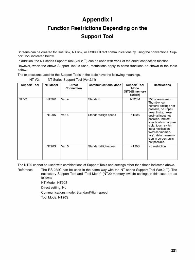
Appendix IFunction Restrictions Depending on the
Support Tool
Screens can be created for Host link, NT link, or C200H direct communications by using the conventional Sup-port Tool indicated below.
In addition, the NT series Support Tool (Ver.2.@) can be used with Ver.4 of the direct connection function.
However, when the above Support Tool is used, restrictions apply to some functions as shown in the tablebelow.
The expressions used for the Support Tools In the table have the following meanings.
NT V2: NT Series Support Tool (Ver.2.@)
The NT20 cannot be used with combinations of Support Tools and settings other than those indicated above.
Reference: The RS-232C can be used in the same way with the NT series Support Tool (Ver.2.@). Thenecessary Support Tool and “Tool Mode” (NT20 memory switch) settings in this case are asfollows:
NT Model: NT20S
Direct setting: No
Communications mode: Standard/High-speed
Tool Mode: NT20S
Support Tool NT Model Direct Connection
Communications Mode Support Tool Mode
(NT20S memory switch)
Restrictions
NT V2 NT20M Ver. 4 Standard NT20M 250 screens max., Thumbwheel numeral settings not possible, no upper/lower limits, hexa-decimal input not possible, indirect specification not pos-sible, touch switch input notification fixed as “momen-tary”, data transmis-sion in screen units not possible.
NT20S Ver. 4 Standard/High-speed NT20S
NT20S Ver. 5 Standard/High-speed NT20S No restriction
281

Function Restrictions Depending on the Support Tool Appendix I
282
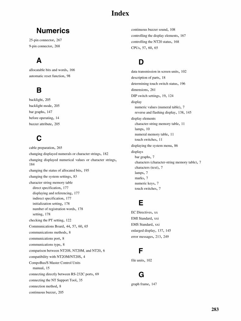
Index
Numerics25-pin connector, 267
9-pin connector, 268
Aallocatable bits and words, 166
automatic reset function, 98
Bbacklight, 205
backlight mode, 205
bar graphs, 147
before operating, 14
buzzer attribute, 205
Ccable preparation, 265
changing displayed numerals or character strings, 182
changing displayed numerical values or character strings,184
changing the status of allocated bits, 195
changing the system settings, 83
character string memory table
direct specification, 177
displaying and referencing, 177
indirect specification, 177
initialization setting, 178
number of registration words, 178
setting, 178
checking the PT setting, 122
Communications Board, 44, 57, 60, 65
communications methods, 8communications port, 8communications type, 8comparison between NT20S, NT20M, and NT20, 6compatibility with NT2OM/NT20S, 4CompoBus/S Master Control Units
manual, 15
connecting directly between RS-232C ports, 69
connecting the NT Support Tool, 35
connection method, 8continuous buzzer, 205
continuous buzzer sound, 108
controlling the display elements, 167
controlling the NT20 status, 168
CPUs, 57, 60, 65
Ddata transmission in screen units, 102
description of parts, 18
determining touch switch status, 196
dimensions, 261
DIP switch settings, 19, 124
display
numeric values (numeral table), 7reverse and flashing display, 138, 145
display elements
character-string memory table, 11
lamps, 10
numeral memory table, 11
touch switches, 11
displaying the system menu, 86
displays
bar graphs, 7characters (character-string memory table), 7characters (text), 7lamps, 7marks, 7numeric keys, 7touch switches, 7
EEC Directives, xx
EMI Standard, xxi
EMS Standard, xxi
enlarged display, 137, 145
error messages, 213, 249
Ffile units, 102
Ggraph frame, 147
283
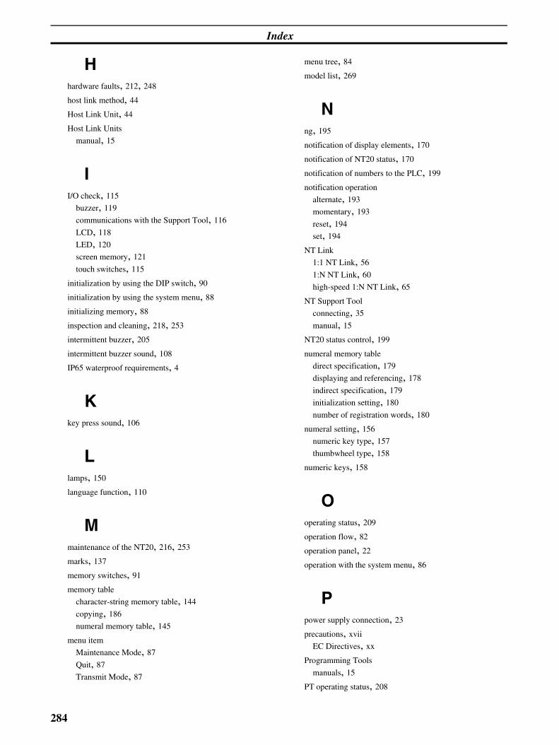
Index
Hhardware faults, 212, 248
host link method, 44
Host Link Unit, 44
Host Link Units
manual, 15
II/O check, 115
buzzer, 119
communications with the Support Tool, 116
LCD, 118
LED, 120
screen memory, 121
touch switches, 115
initialization by using the DIP switch, 90
initialization by using the system menu, 88
initializing memory, 88
inspection and cleaning, 218, 253
intermittent buzzer, 205
intermittent buzzer sound, 108
IP65 waterproof requirements, 4
Kkey press sound, 106
Llamps, 150
language function, 110
Mmaintenance of the NT20, 216, 253
marks, 137
memory switches, 91
memory table
character-string memory table, 144
copying, 186
numeral memory table, 145
menu item
Maintenance Mode, 87
Quit, 87
Transmit Mode, 87
menu tree, 84
model list, 269
Nng, 195
notification of display elements, 170
notification of NT20 status, 170
notification of numbers to the PLC, 199
notification operation
alternate, 193
momentary, 193
reset, 194
set, 194
NT Link
1:1 NT Link, 56
1:N NT Link, 60
high-speed 1:N NT Link, 65
NT Support Tool
connecting, 35
manual, 15
NT20 status control, 199
numeral memory table
direct specification, 179
displaying and referencing, 178
indirect specification, 179
initialization setting, 180
number of registration words, 180
numeral setting, 156
numeric key type, 157
thumbwheel type, 158
numeric keys, 158
Ooperating status, 209
operation flow, 82
operation panel, 22
operation with the system menu, 86
Ppower supply connection, 23
precautions, xvii
EC Directives, xx
Programming Tools
manuals, 15
PT operating status, 208
284
Index
PT status, 208
PT status control area, 12, 168, 203
PT status notify area, 12, 170
Rradiated emission, xxi
Sscreen
child screen, 140
classification, 140
composition of the screen, 136
continuous screen, 141
normal screen, 140
NT20 screen, 136
overlapping screen, 140
parent screen, 140
screen display, 140
screen management, 136
special screen number, 136
switching the continuous screens, 141
screen attributes
backlight attribute, 143
buzzer attribute, 142
numeral setting attribute, 142
screen data, 102
screen display, 203
screen switch setting, 172
screen switch strobe, 174, 209
screen switch timing, 173
screen switching function, 154
screen switching strobe, 171, 173
screens
creating, 134
selecting the host communications method, 93
selecting the host communications port, 94
selecting the host link communications speed, 95
selecting the menu items, 87
selecting the NT link (1
N) communications speed, 96
selecting unit numbers, 97
Serial Communications Board, 44, 61, 65
Serial Communications Boards
manuals, 15
Serial Communications Unit, 44
serial port A, 8serial port B, 8setting the buzzer, 107
smoothing, 137, 145
soldering, 266
specifications, 255
starting the NT20, 83
Support Tool
connecting the NT Support Tool, 35
Support Tool mode setting, 111
switching the screen display, 172
switching to the RUN mode, 105
System Installer
manual, 15
system key functions, 154
system menu, 84
system program
erasing, 127
transferring, 126
system transfer tool, 126
Ttouch switches, 152
transmitting the screen data, 103
Uupgrade bar graphs, 189
upper/lower limit check, 157
using numeric keys, 160
using the thumbwheel type, 161
285

Index
286

Revision History
A manual revision code appears as a suffix to the catalog number on the front cover of the manual.
The following table outlines the changes made to the manual during each revision. Page numbers refer to theprevious version.
Revision code Date Revised content
01 March 2007 Original production
Cat. No. V091-E1-01
Revision code
287

Revision History
288

OMRON CorporationControl Devices Division H.Q.Shiokoji Horikawa, Shimogyo-ku,Kyoto, 600-8530 JapanTel: (81)75-344-7109/Fax: (81)75-344-7149
Regional Headquarters
OMRON EUROPE B.V.Wegalaan 67-69, NL-2132 JD HoofddorpThe NetherlandsTel: (31)2356-81-300/Fax: (31)2356-81-388
OMRON ELECTRONICS LLC1 East Commerce Drive, Schaumburg, IL 60173U.S.A.Tel: (1)847-843-7900/Fax: (1)847-843-8568
OMRON ASIA PACIFIC PTE. LTD.83 Clemenceau Avenue, #11-01, UE Square,Singapore 239920Tel: (65)6835-3011/Fax: (65)6835-2711
OMRON (CHINA) CO., LTD.Room 2211, Bank of China Tower, 200 Yin Cheng Zhong Road,PuDong New Area, Shanghai, 200120 ChinaTel: (86)21-5037-2222/Fax: (86)21-5037-2200

Cat. No.
This ma
Authorized Distributor:
V091-E1-01 Note: Specifications subject to change without notice Printed in Japan
nual is printed on 100% recycled paper.