ns series ball & butterfly valves - a-t controls · 2021. 1. 27. · 2 nsf/ansi 61 & 372...
TRANSCRIPT

UND. LAB. INC. CLFDANSI/NSF 61 also certified to ANSI/NSF 372
<5DZ0>
NS SerieS Ball & Butterfly ValvesNSF/ANSI 61 & 372 Certified
Valves for Water

2 NSF/ANSI 61 & 372 Certified Valves | A-T Controls, Inc. | www.atcontrols.com
Applications• Water Treatment• Potable Water Service• Reverse Osmosis• Desalination
A-T Controls’ NS Series floating ball valves and NS series butterfly valves are certified to meet the requirements of NSF 61 (Drinking Water System Components- Health Affects) and NSF 372 (Drinking Water System Components- Lead Content). This means that NS Series valves are certified for use (by Underwriters Laboratory) in water treatment, water purification, potable water, and water distribution systems and conforms with North American lead content requirements for “lead-free” plumbing.The NS Series valves include a tag showing that the valve assembly is certified to NSF 61 and NSF 372. NS butterfly valves are available in sizes 2” – 24”, and have Class 150 flanges. NS Series ball valves are available with threaded, socket weld, butt weld, Class 150, and Class 300 end connections.
NS Series ValvesCertified NSF 61 & 372 Valve Offering:NS20 1/4” - 3” 2 pc. Regular Port Ball Valve, Threaded Ends,
1000 PSI, Stainless Steel
NS22 1/4” - 3” 2 pc. Full Port Ball Valve, Direct Mount, Threaded Ends, 1000 PSI, Stainless Steel
NS55 1/4” - 4” 3 pc. Full Port Ball Valve, Threaded, Socket Weld or Butt Weld, 800/1000 PSI, Stainless Steel
NS90-F1 1/2” - 4” 2 pc. Flanged Ball Valve, ANSI Class 150, Stainless Steel
NSD9-F1 6” 2 pc. Direct Mount, Flanged Ball Valve, ANSI Class 150, Stainless Steel
NSD9-F3 1/2” - 6” 2 pc. Direct Mount, Flanged Ball Valve, ANSI Class 300, Stainless Steel
NS Series Resilient Seated Butterfly
2” - 24” NSF 61 & 372 and Dead-End Service, Wafer or Lug, ANSI Class 150, Stainless Steel or Ductile Iron body
NSF 61 & 372 CERTIFIED VALVES
VALVENSF/ANSI 61
ALSO CERTIFIED TO NSF/ANSI 372
<5DZ0>

3NSF/ANSI 61 & 372 Certified Valves | A-T Controls, Inc. | www.atcontrols.com
Top Mounting Location for 2-1/2" – 3"
Side Mounting Location for 2-1/2" – 3"
Top View
Side View
W4
W3
L
0A
F
C
SIZE A B C D E F L Y Z AC AD AE DD1 DD2 W3 W4 LBS.
1/4" 0.45 0.197 3.94 0.59 0.88 1.97 2.17 0.39 10-24 1.03 0.31 0.59 0.500 1.122 N/A N/A 0.513/8" 0.49 0.197 3.94 0.60 0.88 1.97 2.17 0.39 10-24 1.02 0.31 0.59 0.500 1.122 N/A N/A 0.511/2" 0.59 0.256 5.12 0.71 1.01 2.36 2.56 0.43 10-24 1.18 0.37 0.63 0.500 1.122 N/A N/A 0.843/4" 0.79 0.256 5.12 0.81 1.01 2.52 2.94 0.43 10-24 1.18 0.37 0.67 0.882 1.378 N/A N/A 1.151" 0.98 0.315 6.50 0.99 1.24 2.80 3.46 0.53 1/4”-20 1.38 0.43 0.80 0.882 1.378 N/A N/A 2.03
1-1/4" 1.26 0.315 6.50 1.20 1.24 3.07 4.02 0.53 1/4”-20 1.38 0.43 0.87 1.000 1.500 N/A N/A 2.911-1/2" 1.50 0.382 7.48 1.58 1.38 3.39 4.33 0.61 1/4”-20 1.64 0.55 0.89 1.000 1.500 N/A N/A 4.19
2” 1.97 0.382 7.48 1.83 1.20 3.74 4.92 0.61 1/4”-20 1.58 0.55 1.02 1.000 1.500 N/A N/A 6.882-1/2" 2.56 0.472 9.84 2.41 2.13 5.12 6.32 0.96 1/4”-20 2.09 0.75 1.22 N/A N/A 2.323 2.402 14.33
3” 3.15 0.472 9.84 2.92 2.17 5.83 7.01 0.96 1/4”-20 2.09 0.75 1.34 N/A N/A 2.756 2.795 20.50
DIMENSIONS (IN)
NO. PART NAME QTY MATERIAL1 BODY 1 ASTM A351 GRADE CF8M2 END CAP 1 ASTM A351 GRADE CF8M
3 BALL 1 1/4" THRU 3/8" ASTM A276 SS316
3 BALL 1 1/2" THRU 3" ASTM A351 GR CF8M
4 STEM 1 ASTM A276 SS3165 STEM NUT 1 AISI 3046 LOCKWASHER 1 AISI 3047 HANDLE 1 AISI 3048 SEAT 2 RTFE9 GLAND NUT 1 AISI 30410 V-RING PACKING * PTFE11 THRUST WASHER 1 PTFE12 HANDLE SLEEVE 1 VINYL13 JOINT GASKET 1 PTFE14 LOCK SADDLE 1 AISI 304
*Regular 1 pc stem packing is used for 1/4” and 3/8”; 1 set of V-Ring packing consists of 2 pcs. of V-Ring for 1/2” -3” models
MATERIALS LIST
• Two piece design• Available in stainless steel• Full port 1000 psi• Threaded ends only
SAMPLE PART #
Valve SeriesEnd Connection
Seat MaterialValve Size Special Designation
Additional SpecialDesignation
NS20-TH-0200-XXX NOTE: Dotted line shows the rating for valve body. Solid line shows the rating for valve seat. Both ratings need to be considered when determining the limitation of the valve for specific application.
TEMPERATURE IN °F (°C)
PR
ESSU
RE
IN P
SIG
PR
ESSUR
E IN B
AR
100
0(-18)
-20(-28)
0100(38)
300
200
400
800
500
600
700
900
1100
1000
500(260)(149)
200 300(93)
400(204)
6.9
0
13.7
20.7
27.6
55.2
34.5
41.4
48.3
62.1
75.9
70.0
600(316)
1/4"~3"
RTFE
Pressure vs Temperature Chartfor Valves 1/4” to 3”
NS 20 &22 Series
PTFEPressure vs. Temperature
VALVENSF/ANSI 61
AND ALSO CERTIFIED TO NSF/ANSI 372
<5DZ0>
2-PC FULL PORT | THREADED Series NS20

4 NSF/ANSI 61 & 372 Certified Valves | A-T Controls, Inc. | www.atcontrols.com
MATERIALS LIST
Series NS22 DIRECT MOUNT | 2-PC FULL PORT | THREADED
NO. PART NAME QTY. MATERIAL Repair Kit
1 BODY 1 ASTM A351 GRADE CF8M 2 END CAP 1 ASTM A351 GRADE CF8M
3 BALL 1 1/4" THRU 3/8" ASTM A276 SS316
3 BALL 1 1/2" THRU 3" ASTM A351 GRADE CF8M
4 SEAT 2 RTFE or PTFE
5 JOINT GASKET 1 PTFE
6 STEM SEAL 1 RTFE
7 STEM 1 ASTM A276 SS3168 GLAND PACKING * PTFE
9 GLAND BUSHING 1 AISI 30410 LOCK SADDLE 1 AISI 30411 STEM NUT 2 AISI 30412 HANDLE 1 AISI 30413 HANDLE SLEEVE 1 VINYL14 STEM WASHER 1 AISI 304
15 BELLEVILLE WASHER 2 AISI 301
16 STOP BOLT 1 AISI 30417 STOP BOLT NUT 1 AISI 30418 GLAND PACKING 1 PTFE
19 HANDLE LOCK 1 AISI 30420 HANDLE NUT 1 AISI 30421 ANTI-STATIC DEVICE 2 AISI 316
* 1/4” - 1/2” - 1 PC 3/4” - 2” - 2 PCS 2-1/2” - 3” - 3 PCS
Valve Dimensions Actuator Mounting Dimensions
Size ØA AB AE J K L M N P R S T U V W X ISO 5211 (LBS)
1/4" 0.45 1.28 0.55 1.52 5.91 2.56 3.03 0.25 0.354 0.43 0.26 1.969 0.28 1.654 0.26 1.417 F03/F04/F05 1.23
3/8" 0.49 1.28 0.55 1.52 5.91 2.56 3.03 0.25 0.354 0.43 0.26 1.969 0.28 1.654 0.26 1.417 F03/F04/F05 1.23
1/2" 0.59 1.28 0.53 1.52 6.30 2.56 3.03 0.25 0.354 0.43 0.26 1.969 0.28 1.654 0.26 1.417 F03/F04/F05 1.23
3/4" 0.79 1.47 0.61 1.81 6.30 2.94 3.35 0.27 0.354 0.43 0.26 1.969 0.28 1.654 0.26 1.417 F03/F04/F05 1.32
1" 0.98 1.73 0.72 2.23 6.50 3.46 3.78 0.42 0.433 0.56 0.24 1.969 0.28 1.654 0.24 N/A F04/F05 2.4
1-1/4" 1.26 2.01 0.81 2.40 6.50 4.02 3.94 0.42 0.433 0.56 0.24 1.969 0.28 1.654 0.24 N/A F04/F05 3.31
1-1/2" 1.50 2.17 0.76 3.05 8.46 4.33 5.00 0.54 0.551 0.75 0.30 2.756 0.35 1.969 0.30 N/A F05/F07 5.62
2" 1.97 2.46 0.89 3.35 8.46 4.92 5.28 0.54 0.551 0.75 0.30 2.756 0.35 1.969 0.30 N/A F05/F07 7.93
2-1/2" 2.56 3.16 1.09 4.28 10.35 6.32 6.57 0.65 0.669 0.88 0.39 4.016 0.47 2.756 0.39 N/A F07/F10 16.38
3" 3.15 3.51 1.19 4.62 12.32 7.01 6.89 0.70 0.669 0.88 0.39 4.016 0.47 2.756 0.39 N/A F07/F10 22.81
DIMENSIONS (IN)
AE
R
L
A
N
SIZE Cv
1/4" 73/8" 81/2" 153/4" 401" 70
1-1/4" 1101-1/2" 250
2" 3502-1/2” 600
3” 900
Break Away Torque for RTFE Seats
SIZE IN-LBS.
1/4" 623/8" 621/2" 623/4" 711" 124
1-1/4" 1591-1/2" 230
2" 3192-1/2” 487
3” 770NOTE: For other seatmaterial, consult factory
STANDARDSDesign ANSI/ASME B16.34End Connections ASME B1.20.1Sulfide Stress Protection NACE MR0175Mounting ISO 5211Marking System for Valves MSS SP-25, MSS SP-55Safety Integrity IEC 61508:2010; SIL 3Material Certification EN 10204-3.1 MTRSafety NSF/ANSI 61-2016
NSF/ANSI 372-2011Quality Assurance ISO 9001:2015
SAMPLE PART #
Valve SeriesEnd Connection
Seat MaterialValve Size Special Designation
Additional SpecialDesignation
NS22-TH-0200-XXX
NOTE: Dotted line shows the rating for valve body. Solid line shows the rating for valve seat. Both ratings need to be considered when determining the limitation of the valve for specific application. Consult factory for other seat materials.
TEMPERATURE IN °F (°C)
PR
ESSU
RE
IN P
SIG
PR
ESSUR
E IN B
AR
100
0(-18)
-20(-28)
0100(38)
300
200
400
800
500
600
700
900
1100
1000
500(260)(149)
200 300(93)
400(204)
6.9
0
13.7
20.7
27.6
55.2
34.5
41.4
48.3
62.1
75.9
70.0
600(316)
1/4"~3"
RTFE
Pressure vs Temperature Chartfor Valves 1/4” to 3”
NS 20 &22 Series
PTFE
Pressure vs. Temperature
VALVENSF/ANSI 61
ALSO CERTIFIED TO NSF/ANSI 372
<5DZ0>

5NSF/ANSI 61 & 372 Certified Valves | A-T Controls, Inc. | www.atcontrols.com
3-PC FULL PORT | TH, SW, BW Series NS55
Valve Dimensions Actuator Mounting Dimensions
Size A B C D E F H K L L1 M T Y Z AC AD DD ISO 5211 (LBS)
1/4" 0.46 0.256 5.12 1.15 0.78 2.95 0.56 0.39 2.51 2.47 0.64 0.06 0.29 M5 0.98 0.374 1.417 F03 1.4
3/8" 0.50 0.256 5.12 1.15 0.78 2.95 0.69 0.39 2.51 2.47 0.69 0.06 0.29 M5 0.98 0.374 1.417 F03 1.4
1/2" 0.59 0.256 5.12 1.15 0.78 2.95 0.86 0.39 2.59 2.59 0.89 0.06 0.29 M5 0.98 0.374 1.417 F03 1.4
3/4" 0.79 0.256 5.12 1.28 0.69 3.03 1.07 0.51 3.00 3.00 1.08 0.06 0.25 M5 0.98 0.374 1.417 F03 1.7
1" 0.98 0.315 6.30 1.53 0.81 3.35 1.33 0.51 3.39 3.39 1.34 0.06 0.48 M5 1.18 0.433 1.654 F04 2.4
1-1/4" 1.26 0.315 6.30 1.59 0.96 3.62 1.69 0.51 4.05 4.05 1.68 0.06 0.43 M5 1.18 0.433 1.654 F04 3.7
1-1/2" 1.50 0.382 7.28 1.82 1.22 4.02 1.93 0.51 4.70 4.70 1.91 0.06 0.54 M6 1.38 0.551 1.969 F05 5.5
2" 1.97 0.382 7.28 2.15 1.22 4.33 2.41 0.63 5.17 5.17 2.38 0.06 0.54 M6 1.38 0.551 1.969 F05 8.0
2-1/2" 2.56 0.472 10.24 2.81 1.68 5.91 2.91 0.63 6.46 6.46 3.00 0.08 0.91 M8 2.17 0.748 2.756 F07 16.2
3" 3.15 0.472 10.24 3.33 1.55 6.38 3.54 0.63 7.19 7.19 3.54 0.08 0.74 M10 2.76 0.748 4.016 F10 23.5
4" 3.94 0.591 11.42 4.19 2.06 7.48 4.55 0.79 9.28 9.30 4.57 0.14 1.35 M10 2.76 0.945 4.016 F10 43.7
DIMENSIONS (IN)
SIZE Cv
1/4" 7
3/8" 8
1/2" 15
3/4" 40
1" 70
1-1/4" 110
1-1/2" 250
2" 400
2-1/2" 600
3" 1100
4" 2000
FOR OTHER SEAT MATERIAL CONSULT
FACTORY
Break Away Torque for RTFE Seats
SIZE IN-LBS.
1/4" 62
3/8" 62
1/2" 62
3/4" 80
1" 141
1-1/4" 150
1-1/2" 257
2" 319
2-1/2" 522
3" 691
4" 1151
MATERIALS LISTNO. PART NAME QTY. STAINLESS STEEL Repair
Kit
1 BODY 1 ASTM A351 GRADE CF8M
2 TH END CAP 2 ASTM A351 GRADE CF8M
2 BW/SW END CAP 2 ASTM A351 GRADE CF3M
3 BALL 1 1/4" THRU 3/8" ASTM A276 SS316
3 BALL 1 1/2" THRU 4" ASTM A351 GR CF8M
4 STEM 1 ASTM A276 SS316
5 STEM NUT 2 AISI 304
6 BELLEVILLE WASHER 2 AISI 301
7 HANDLE 1 AISI 304
8 SEAT 2 RTFE or PTFE
9 GLAND BUSHING 1 AISI 304
10 GLAND PACKING 1 set PTFE
11 THRUST WASHER 1 RTFE
12 LOCK SADDLE 1 AISI 304
13 JOINT GASKET 2 PTFE
14 BODY BOLT/STUD * ASTM A193 GRADE B8
15 STOP BOLT 1 AISI 304
16 HANDLE SLEEVE 1 VINYL
17 BODY NUT # ASTM A194 GRADE 8
18 LOCK WASHER # AISI 304
19 STEM WASHER 1 AISI 304
20 HANDLE LOCK 1 AISI 304
* 1/4” THRU 3” QTY = 4 PCS 4” QTY = 6 PCS
# 1/4” THRU 2” QTY = 4 PCS 2-1/2” THRU 3” QTY = 8 PCS 4” QTY = 12 PCS
TEMPERATURE IN °F (°C)
PR
ESSU
RE
IN P
SIG
PR
ESSUR
E IN B
AR
100
0(-18)
-20(-28)
0100(38)
300
200
400
800
500
600
700
900
1100
1000
500(260)(149)
200 300(93)
400(204)
6.9
0
13.7
20.7
27.6
55.2
34.5
41.4
48.3
62.1
75.9
70.0
600(316)
1/4"~2"
RTFE
Pressure vs Temperature Chartfor Valves 1/4” to 4”
55 Series
2-1/2 ~4"
PTFE
Pressure vs. Temperature
STANDARDSDesign ANSI/ASME B16.34End Connections ASME B1.20.1, B16.11Pressure Testing API 598Mounting ISO 5211Marking System for Valves MSS SP-25Material Certification EN 10204-3.1 MTRSafety NSF/ANSI 61-2016 NSF/ANSI 372-2011Quality Assurance ISO 9001:2015
SAMPLE PART #
NS55-TH-0300-XXXValve Series
End ConnectionValve Size
Seat MaterialSpecial Designation
Additional Special Designation
VALVENSF/ANSI 61
ALSO CERTIFIED TO NSF/ANSI 372
<5DZ0>

6 NSF/ANSI 61 & 372 Certified Valves | A-T Controls, Inc. | www.atcontrols.com
Series NS90-F1 CLASS 150 | 1/2” - 2-1/2”
MATERIALS LIST (1/2” - 2-1/2”)
NO. PART NAME QTY. MATERIAL Repair Kit
1 BODY 1 ASTM A351 GRADE CF8M
2 END CAP 1 ASTM A351 GRADE CF8M
3 BALL 1 ASTM A351 GRADE CF8M
4 SEAT 2 RTFE or PTFE
5 JOINT GASKET 1 PTFE
6 STEM 1 ASTM A276 SS3167 STEM SEAL 1 RTFE
8 GLAND PACKING ^ PTFE
9 GLAND PACKING 1 PTFE
10 GLAND BUSHING 1 AISI 30411 BELLEVILLE WASHER 2 AISI 30112 LOCKING PLATE 1 AISI 30413 LOCK SADDLE 1 AISI 30414 STEM NUT 2 AISI 30415 HANDLE LOCK 1 AISI 30416 HANDLE 1 AISI 30417 HANDLE SLEEVE 1 VINYL18 STOP BOLT 1 AISI 30419 BODY STUD * ASTM A193 GRADE B8 20 BODY STUD NUT * ASTM A194 GRADE 8 21 ANTI-STATIC DEVICE 2 AISI 316
^1/2” - 1” - 2 PCS 1-1/2” - 2-1/2” - 3 PCS
*1/2” - 2” - 4 PCS 2-1/2” - 8 PCS
L
E
D
A R H
N
AC
Valve Dimensions Actuator Mounting Dimensions
Size ØA ØB ØC D E F G H J K L M ØAC N N1 P R S T ISO 5211 (LBS)
1/2" 0.59 1.38 3.50 0.44 0.06 0.63 4 2.38 1.36 6.69 4.26 3.15 1.18 0.36 0.91 0.315 0.44 M5 1.654 F04 3.7
3/4" 0.79 1.69 3.88 0.44 0.06 0.63 4 2.75 1.65 6.69 4.62 3.43 1.18 0.40 0.91 0.315 0.44 M5 1.654 F04 4.6
1" 0.98 2.00 4.25 0.56 0.06 0.63 4 3.12 1.96 8.15 5.00 4.06 1.38 0.32 0.93 0.382 0.56 M6 1.969 F05 6.8
1-1/2" 1.50 2.88 5.00 0.75 0.06 0.63 4 3.88 3.08 10.28 6.50 6.02 2.17 0.58 1.37 0.472 0.75 M8 2.756 F07 13.6
2" 1.97 3.62 6.00 0.75 0.06 0.75 4 4.75 3.40 10.28 7.02 6.38 2.17 0.58 1.37 0.472 0.75 M8 2.756 F07 19.2
2-1/2" 2.56 4.12 7.00 0.75 0.06 0.75 4 5.50 3.83 10.28 7.48 6.81 2.17 0.58 1.37 0.472 0.75 M8 2.756 F07 30
DIMENSIONS (IN)
VALVE SIZE VALVE Cv
1/2” 153/4” 451” 85
1-1/2” 2752” 460
2-1/2” 7003” 1,1004” 2,200
STANDARDSDesign ANSI/ASME B16.34Face to Face ANSI/ASME B16.10Flange Dimensions ANSI/ASME B16.5Pipeline Valves API 6DPressure Testing API 598Mounting ISO 5211Marking System for Valves MSS SP-25Safety Integrity IEC 61508:2010; SIL 3
NSF/ANSI 61-2016 NSF/ANSI 372-2011
Material Certification EN 10204-3.1 MTRQuality Assurance ISO 9001:2015
BREAKAWAY TORQUES
SIZE IN-LBS1/2" 923/4" 1271" 150
1-1/2" 3112" 396
2-1/2" 6573" 9804" 1,700
SAMPLE PART #
Valve Series
Special Designation
End Connection
Seat MaterialValve Size
Additional Special Designation
NS90-F1-0200-XXX
Series NS90-F1• 2 pc. Flanged Ball Valve• ANSI Class 150• 1/2” - 2-1/2”
VALVENSF/ANSI 61
ALSO CERTIFIED TO NSF/ANSI 372
<5DZ0>

7NSF/ANSI 61 & 372 Certified Valves | A-T Controls, Inc. | www.atcontrols.com
3” - 4” | CLASS 150 Series NS90-F1
Valve Dimensions Actuator Mounting Dimensions
Size ØA ØB ØC D E F G H J K L M ØAC N N1 P R S T ISO 5211 (LBS)
3" 3.15 5.00 7.50 0.75 0.06 0.75 4 6.00 4.23 14.37 8.01 6.95 2.76 0.93 1.81 0.591 0.94 M10 4.016 F10 41
4" 3.94 6.19 9.00 0.94 0.06 0.75 8 7.50 4.82 14.37 9.00 7.52 2.76 0.93 1.81 0.591 0.94 M10 4.016 F10 65
DIMENSIONS (IN)
MATERIALS LIST (3” - 4”)
NO. PART NAME QTY. MATERIAL Repair Kit
1 BODY 1 ASTM A351 GRADE CF8M 2 END CAP 1 ASTM A351 GRADE CF8M 3 BALL 1 ASTM A351 GRADE CF8M4 SEAT 2 RTFE or PTFE
5 JOINT GASKET 1 PTFE
6 STEM 1 ASTM A276 SS3167 STEM SEAL 1 RTFE
8 GLAND PACKING 3 PTFE
9 GLAND PACKING 1 PTFE
10 GLAND BUSHING 1 AISI 30411 BELLEVILLE WASHER 2 AISI 30112 LOCKING PLATE 1 AISI 30413 LOCK SADDLE 1 AISI 30414 STEM NUT 1 AISI 30415 HANDLE BOLT 2 AISI 30416 HANDLE HUB 1 AISI 30417 STOP PIN 1 AISI 30418 BODY BOLT 8 ASTM A193 GRADE B8 19 BODY NUT 8 ASTM A194 GRADE 820 HANDLE BAR 1 AISI 30421 HANDLE SLEEVE 1 VINYL22 ANTI-STATIC DEVICE 2 AISI 316
H CA
L
D
E
R
N
AC
NOTE: Dotted line shows the rating for valve body. Solid line shows the rating for valve seat. Both ratings need to be considered when determining the limitation of the valve for specific application.Consult factory for other seat materials.
TEMPERATURE IN °F (°C)
PRES
SURE
IN P
SIG
PRESSURE IN
BAR
Pressure vs Temperature Chartfor Valves 1/2” to 12”
NS90 & NSD9-F1 Series
Valve Body
(-28)-20
0
50
100
150
200
250
(-18) (38)0 100
(93)200
300
350
400
450
500
550
400(204)(149)
300(260)500
0
3.5
6.9
10
14
17
21
24
28
31
34
38
Class 150
(316)600
RTFE
PTFE
Pressure vs. Temperature Chart
Series NS90-F1• 2 pc. Flanged Ball Valve• ANSI Class 150• 3” - 4”
8 NSF/ANSI 61 & 372 Certified Valves | A-T Controls, Inc. | www.atcontrols.com
R
L
E
D
A H C
N
Valve Dimensions Actuator Mounting Dimensions
Size ØA ØB ØC D E F G H J K L M N P R S T U V ISO 5211 (LBS)
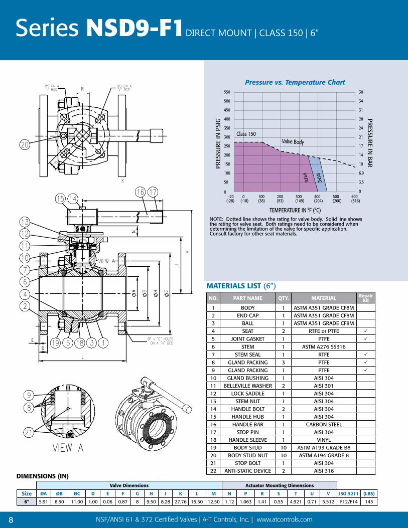
6" 5.91 8.50 11.00 1.00 0.06 0.87 8 9.50 8.28 27.76 15.50 12.50 1.12 1.063 1.41 0.55 4.921 0.71 5.512 F12/F14 145
DIMENSIONS (IN)
MATERIALS LIST (6”)
NO. PART NAME QTY. MATERIAL Repair Kit
1 BODY 1 ASTM A351 GRADE CF8M 2 END CAP 1 ASTM A351 GRADE CF8M 3 BALL 1 ASTM A351 GRADE CF8M4 SEAT 2 RTFE or PTFE
5 JOINT GASKET 1 PTFE
6 STEM 1 ASTM A276 SS3167 STEM SEAL 1 RTFE
8 GLAND PACKING 3 PTFE
9 GLAND PACKING 1 PTFE
10 GLAND BUSHING 1 AISI 30411 BELLEVILLE WASHER 2 AISI 30112 LOCK SADDLE 1 AISI 30413 STEM NUT 1 AISI 30414 HANDLE BOLT 2 AISI 30415 HANDLE HUB 1 AISI 30416 HANDLE BAR 1 CARBON STEEL17 STOP PIN 1 AISI 30418 HANDLE SLEEVE 1 VINYL19 BODY STUD 10 ASTM A193 GRADE B820 BODY STUD NUT 10 ASTM A194 GRADE 821 STOP BOLT 1 AISI 30422 ANTI-STATIC DEVICE 2 AISI 316
NOTE: Dotted line shows the rating for valve body. Solid line shows the rating for valve seat. Both ratings need to be considered when determining the limitation of the valve for specific application.Consult factory for other seat materials.
TEMPERATURE IN °F (°C)PR
ESSU
RE IN
PSI
G
PRESSURE IN
BAR
Pressure vs Temperature Chartfor Valves 1/2” to 12”
NS90 & NSD9-F1 Series
Valve Body
(-28)-20
0
50
100
150
200
250
(-18) (38)0 100
(93)200
300
350
400
450
500
550
400(204)(149)
300(260)500
0
3.5
6.9
10
14
17
21
24
28
31
34
38
Class 150
(316)600
RTFE
PTFE
Pressure vs. Temperature Chart
Series NSD9-F1DIRECT MOUNT | CLASS 150 | 6”

9NSF/ANSI 61 & 372 Certified Valves | A-T Controls, Inc. | www.atcontrols.com
6” | CLASS 150 | DIRECT MOUNT Series NSD9-F1
Series NSD9-F1• 2 pc. Direct Mount
Flanged Ball Valve• ANSI Class 150• 6”
STANDARDSDesign ANSI/ASME B16.34Face to Face ANSI/ASME B16.10
Flange Dimensions ANSI/ASME B16.5Pipeline Valves API 6DPressure Testing API 598Mounting ISO 5211Marking System for Valves MSS SP-25Safety Integrity IEC 61508:2010; SIL 3
NSF/ANSI 61-2016 NSF/ANSI 372-2011
Material Certification EN 10204-3.1 MTRQuality Assurance ISO 9001:2015
NSD9-F1-0600-XXXSAMPLE PART #
Valve Series
End Connection
Valve Size Seat Material
Special Designation
Additional SpecialDesignation
VALVENSF/ANSI 61
ALSO CERTIFIED TO NSF/ANSI 372
<5DZ0>
VALVE SIZE VALVE Cv
6” 5,150
Break Away Torque for RTFE Seats
SIZE IN-LBS.
6" 2,550
30°
30° V-Port
60°
60° V-Port
90°
90° V-Port
Custom Cut
Note: May be customized; call factory for flow analysis design.
* Refer to pg 3 of the V-Series Control Port Ball Valve Catalog
for Cv values.
“V” SERIES Control Port B
all Valves
Triac “V” Series Ball Valves are ideal for achieving
more precise control with the simplicity and
sealing features of a ball valve. We offer them
1/2” – 4” in a 3-piece design and 1/2”– 6”
flanged. The standard “V” notch options are 30°,
60° & 90°. While they are available as manual
valves, we specialize in automating them to suit
your particular control requirements.
Chevron Packing
Belleville Washer
Lock Saddle
Gland
Anti-Static Device
BushingViton® O-ring
Stem Nut
Pyramidal (45°) Stem & Stem Seal
Germany Patent No. 299 02 532.2United States Patent No. 5,954,088China Patent No. ZL 98 2 09161.3
(Other material available; not on V7)
Easy to Automate!See automated data sheets for pre-sized assemblies
Pneumatic Electric
9955 International Blvd.Cincinnati, Ohio 45246www.atcontrols.com
PHONE (513) 247-5465FAX (513) [email protected]
®
“V” SeriesControl PortBall ValvesSizes 1/2”-4”, 3-Piece (V7, V8)
Sizes 1/2”-6”, 150# Flanged (V9)
Sizes 1/2”-6”, 300# Flanged (FVD9)
316SST or WCB
30°, 60° & 90° “V” Notch StandardOthers on Request
HOW TO ORDER MANUAL VALVES SAMPLE PART #
V8C-TH-0200-XXX
See part number matrix for itemized options
V Port
Valve Series
Carbon Steel
Threaded Ends
Valve Size
Seat Material
Special Designation
Additional Special Designation (30°, 60°, or 90° v-ball)
NSV9 Series: The NS90 & NSD9 Series’ are available with a v-port ball option (30°, 60°, or 90° V-notch). V-port valves offer better and more consistent control than traditional round ported ball valves. We offer this valve with the control port cast and machined into the ball, not in the seat. This allows for much better flow characteristics and eliminates the need to replace seats. The 30° option allows for finer tapered control throughout the valve rotation, and the 60° & 90° offer a larger Cv in addition to controlled flow.
The RTFE seat is standard in the both the NSV9 and NSD9 Class 150 and Class 300.
Series NSV9• 2 pc. Flanged Ball Valve• V-Port• ANSI Class 150 or 300• 1/2”- 6”
NSV9-F1-0600-XXX-6SAMPLE PART #
Valve Series
End Connection
Valve Size Seat Material
Special Designation
Additional SpecialDesignation
Port Designation

10 NSF/ANSI 61 & 372 Certified Valves | A-T Controls, Inc. | www.atcontrols.com
Series NSD9-F3 DIRECT MOUNT | CLASS 300 | 1/2” - 2-1/2”
R
L
ED
A H
N
Series NSD9-F3• 2 pc. Direct Mount
Flanged Ball Valve• ANSI Class 300• 1/2” - 2-1/2”
Valve Dimensions Actuator Mounting Dimensions
Size ØA ØB ØC D E F G H J K L M N P R S T U V ISO 5211 (LBS)
1/2" 0.59 1.38 3.75 0.56 0.06 0.63 4 2.62 1.92 6.50 5.50 3.33 0.39 0.433 0.55 0.26 1.654 0.28 1.969 F04/F05 5
3/4" 0.79 1.69 4.62 0.62 0.06 0.75 4 3.25 2.50 6.50 6.00 3.92 0.41 0.433 0.55 0.26 1.654 0.28 1.969 F04/F05 8
1" 0.98 2.00 4.88 0.69 0.06 0.75 4 3.50 2.50 6.50 6.50 3.92 0.41 0.433 0.55 0.26 1.654 0.28 1.969 F04/F05 10.5
1-1/2" 1.50 2.88 6.12 0.81 0.06 0.87 4 4.50 3.51 10.31 7.50 5.79 0.75 0.748 0.94 0.39 2.756 0.47 4.016 F07/F10 22
2" 1.97 1.26 6.50 0.88 0.06 0.75 8 5.00 3.80 10.31 8.50 6.09 0.75 0.748 0.94 0.39 2.756 0.47 4.016 F07/F10 28.5
2-1/2" 2.56 4.12 7.50 1.00 0.06 0.87 8 5.88 4.57 10.31 9.50 6.85 0.75 0.748 0.94 0.39 2.756 0.47 4.016 F07/F10 42
DIMENSIONS (IN)
NOTE: Dotted line shows the rating for valve body. Solid line shows the rating for valve seat. Both ratings need to be considered when determining the limitation of the valve for specific application. Consult factory for other seat materials.
Pressure vs. Temperature Chartfor Valves 1/2” to 6”
TEMPERATURE IN °F (°C)
PRES
SUR
E IN
PSI
G
PRESSU
RE IN
BAR
Pressure vs Temperature Chartfor Valves 1/2” to 6”
NSD9-F3 Series
Valve Body
(-28)-20
0
100
200
300
400
500
(-18) (38)0 100
(93)200
600
700
800
900
1000
1100
400(204)(149)
300(260)500
0
7
14
21
28
34
41
48
55
62
69
75
Class 300
(316)600
RTFEPTFE
STANDARDSDesign ANSI/ASME B16.34Face to Face ANSI/ASME B16.10Flange Dimensions ANSI/ASME B16.5Pipeline Valves API 6DPressure Testing API 598Sulfide Stress Protection NACE MR0175Safety Integrity IEC 61508:2010; SIL 3 NSF/ANSI 61-2016 NSF/ANSI 372-2011Mounting ISO 5211Marking System for Valves MSS SP-25Material Certification EN 10204-3.1 MTRQuality Assurance ISO 9001:2015
MATERIALS LIST (1/2” - 2-1/2”)
NO. PART NAME QTY. MATERIAL Repair Kit
1 BODY 1 ASTM A351 GRADE CF8M 2 END CAP 1 ASTM A351 GRADE CF8M 3 BALL 1 ASTM A351 GRADE CF8M4 SEAT 2 RTFE or PTFE
5 JOINT GASKET 1 PTFE
6 STEM 1 ASTM A276 SS3167 STEM SEAL 1 RTFE
8 GLAND PACKING & PTFE
9 GLAND PACKING 1 PTFE
10 GLAND BUSHING 1 AISI 30411 BELLEVILLE WASHER 2 AISI 30112 LOCK SADDLE 1 AISI 30413 STEM NUT 2 AISI 30414 STEM WASHER 1 AISI 30415 HANDLE 1 AISI 30416 HANDLE SLEEVE 1 VINYL17 BODY STUD * ASTM A193 GRADE B8 18 BODY STUD NUT * ASTM A194 GRADE 819 STOP BOLT 1 AISI 30420 STOP BOLT NUT 1 AISI 30421 HANDLE LOCK 1 AISI 30422 STOP BOLT WASHER 1 AISI 30423 ANTI-STATIC DEVICE 2 AISI 316
* 1/2” - 2” - 4 PCS 2-1/2” - 8 PCS& 1/2” - 1” - QTY 2 1-1/2” - 2-1/2” - QTY 3
NSD9-F3-0200-XXXSAMPLE PART #
Valve Series
End Connection
Valve Size Seat Material
Special Designation
Additional SpecialDesignation
VALVENSF/ANSI 61
ALSO CERTIFIED TO NSF/ANSI 372
<5DZ0>

11NSF/ANSI 61 & 372 Certified Valves | A-T Controls, Inc. | www.atcontrols.com
R
L
E
D
A H C
N
3” - 6” | CLASS 300 | DIRECT MOUNT Series NSD9-F3
Series NSD9-F3• 2 pc. Direct Mount
Flanged Ball Valve• ANSI Class 300• 3” - 6”
Valve Dimensions Actuator Mounting Dimensions
Size ØA ØB ØC D E F G H J K L M N P R S T U V ISO 5211 (LBS)
3” 3.15 5.00 8.25 1.12 0.06 0.87 8 6.62 5.22 14.37 11.12 8.05 0.91 0.866 1.18 0.47 4.016 0.55 4.921 F10/F12 59
4" 3.94 6.19 10.00 1.25 0.06 0.87 8 7.88 6.18 14.37 12.00 9.00 0.91 0.866 1.18 0.47 4.016 0.55 4.921 F10/F12 96
6" 5.91 8.50 12.50 1.44 0.06 0.87 12 10.62 8.28 27.76 15.87 12.50 1.12 1.063 1.41 0.55 4.921 0.71 5.512 F12/F14 213
DIMENSIONS (IN)
Break Away Torque for RTFE Seats
SIZE IN-LBS1/2" 125
3/4" 175
1" 220
1-1/2" 450
2" 525
2-1/2" 750
3" 1,400
4" 1,900
6" 3,050
VALVE SIZE VALVE Cv
1/2" 15
3/4" 45
1" 85
1-1/2" 275
2" 450
2-1/2" 700
3" 1,100
4" 2,200
6" 5,150
MATERIALS LIST (3” - 6”)
NO. PART NAME QTY. MATERIAL Repair Kit
1 BODY 1 ASTM A351 GRADE CF8M 2 END CAP 1 ASTM A351 GRADE CF8M 3 BALL 1 ASTM A351 GRADE CF8M4 SEAT 2 RTFE or PTFE
5 JOINT GASKET 1 PTFE
6 STEM 1 ASTM A276 SS3167 STEM SEAL 1 RTFE
8 GLAND PACKING 3 PTFE
9 GLAND PACKING 1 PTFE
10 GLAND BUSHING 1 AISI 30411 BELLEVILLE WASHER 2 AISI 30112 LOCK SADDLE 1 AISI 30413 STEM NUT 1 AISI 30414 HANDLE BOLT 2 AISI 30415 HANDLE HUB 1 AISI 304
16 HANDLE BAR 1 3” - 4” - AISI 304 6” - CARBON STEEL
17 STOP PIN 1 AISI 30418 HANDLE SLEEVE 1 VINYL19 BODY STUD # ASTM A193 GRADE B820 BODY STUD NUT # ASTM A194 GRADE 821 STOP BOLT 1 AISI 30422 ANTI-STATIC DEVICE 2 AISI 316
# 3” - 4” - QTY 8 6” - QTY 10

12 NSF/ANSI 61 & 372 Certified Valves | A-T Controls, Inc. | www.atcontrols.com
Series NS RESILIENT SEATED BUTTERFLY
* Refer to the Resilient Seated Butterfly Valve Catalog for NS Series Automated Package
Sizing and other material options, when NSF 61 is not required.
VALVENSF/ANSI 61
ALSO CERTIFIED TO NSF/ANSI 372
<5DZ0>
STANDARDSDesign API 609, ASME B16.34,
ASME B16.42, MSS SP-67Face to Face API 609
End Connection ASME B16.5 (Class 150), PN 10/16 (Wafer only)
Pressure Testing API 598Mounting ISO 5211Markings API 609, ASME B16.34,
MSS SP-25Material Certification EN 10204-3.1 MTR
Quality Assurance ISO 9001:2015
CERTIFICATIONS
Drinking Water System Components
NSF/ANSI 61 & 372Health Effects & Lead Content
Canada Registration CRN 0C20682.5ABS Approval (Pending)
Page ReferencePage 12 ........Product Details and StandardsPage 13 ........Bill of Materials 2”-14”Page 14 ........Bill of Materials 16”-24”Page 15 ........DimensionsPage 16 ........Cv Values and Operating Torques and
Pressure & Temperature RatingsPage 17 ........Handles and Gear Operator SizingPage 18 ........Automation Capabilities Page 19 ........How To Order: NS Series Part Number Matrix
» Bi-directional, bubble tight shutoff for full-pressure differential
» Vulcanized Molded rubber seat design » ASTM A395 DI & A351 CF8M body
materials » Multiple disc materials available » Square stems and ISO 5211 mounting
pad for direct mounting
Series NSNSF 61 & 372 rated, Dead-End ServiceManual and Automated Butterfly ValvesLug or Wafer body, ANSI 125/150 flanges

13NSF/ANSI 61 & 372 Certified Valves | A-T Controls, Inc. | www.atcontrols.com
RESILIENT SEATED BUTTERFLY Series NS
Bill of Materials (2”-14”)ITEM DESCRIPTION MATERIAL QTY.
1 Body ASTM A395 / A351 CF8M 1
2 Seat EPDM 1
3 Disc A351 CF8M / Nylon Coated DI 1
4 Upper Stem* 17-4 PH® 1
5 Lower Stem* 17-4 PH® 1
6 Flange Bushing Brass 2
7 Bushing Brass 3**
8 O-Ring Buna-N 1
9 X-Ring Buna-N 1
10 Bushing PTFE 1
11 Stem Retainer ASTM A276 304 1
12 Thrust Washer ASTM A276 304 1
13 Snap Ring SK7 Steel 1
*2”-3” valves have a one-piece stem
**one bushing(7) is not shown; it is located below lower stem flange bushing(6)
Bill of Materials | 2” - 14”

14 NSF/ANSI 61 & 372 Certified Valves | A-T Controls, Inc. | www.atcontrols.com
Bill of Materials (16”-24”)ITEM DESCRIPTION MATERIAL QTY.
1 Body ASTM A395 / A351 CF8M 1
2 Seat EPDM 1
3 Disc A351 CF8M / Nylon Coated DI 1
4 Upper Stem 17-4 PH® 1
5 Lower Stem 17-4 PH® 1
6 Bottom Cover Bolt A2-70 4
7 Bottom Cover Lock Washer ASTM A276 304 4*
8 Bottom Cover Flat Washer ASTM A276 304 4*
9 Bottom Cover O-Ring Buna-N 4*
10 Bottom Cover ASTM A395 / A351 CF8M 1
11 Flange Bushing Brass 2
12 Long Bushing Brass 2
13 Short Bushing PTFE 2
14 Packing Buna-N 1
15 Gland WCB / ASTM A276 316 1
16 Gland Bolt ASTM A276 304 4
*16”-20” valves have quantity 2
Bill of Materials | 16” - 24”
Series NS RESILIENT SEATED BUTTERFLY

15NSF/ANSI 61 & 372 Certified Valves | A-T Controls, Inc. | www.atcontrols.com
ANSI/ASME Class 150
SizeA B
D E ØF ØG H ØF1 ØG1 H1 K ØM1 N1ØM2 N2 ØP
ØR ØS T Lug (lbs)
Wafer (lbs)Lug Wafer Lug Wafer Class
150PN 10 (mm)
PN 16 (mm)
Class 150 PN 10 PN 16 Class
150PN 10 (mm)
PN 16 (mm)
2" 3.15 2.40 5.51 5.51 0.63 1.69 0.39 2.756 (F07) 4 - - - 0.354 5/8 - 11 4 0.79 19 19 2 2 2 4.75 125 125 2.07 3.54 0.51 8 6
2-1/2" 3.50 2.68 5.91 5.91 0.63 1.81 0.39 2.756 (F07) 4 - - - 0.354 5/8 - 11 4 0.79 19 19 2 2 2 5.50 145 145 2.53 3.54 0.51 9 7
3" 3.74 2.99 6.22 6.22 0.63 1.81 0.39 2.756 (F07) 4 - - - 0.354 5/8 - 11 4 0.79 19 19 2 2 2 6.00 160 160 3.10 3.54 0.51 11 8
4" 4.49 3.62 6.93 6.93 0.63 2.05 0.39 2.756 (F07) 4 - - - 0.433 5/8 - 11 8 0.79 19 19 2 2 2 7.50 180 180 4.09 3.54 0.55 19 12
5" 5.00 4.21 7.48 7.48 0.71 2.20 0.39 2.756 (F07) 4 - - - 0.551 3/4 - 10 8 0.91 19 19 2 2 2 8.50 210 210 4.85 3.54 0.55 25 16
6" 5.47 4.72 8.35 8.31 0.71 2.20 0.39 2.756 (F07) 4 0.47 4.016 (F10) 4 0.551 3/4 - 10 8 0.91 23 23 2 2 2 9.50 240 240 6.13 4.92 0.55 30 18
8" 6.85 5.94 9.29 9.25 0.71 2.36 0.47 4.016 (F10) 4 0.71 5.512 (F14) 4 0.669 3/4 - 10 8 0.91 23 23 2 2 2 11.75 295 295 7.97 6.89 0.63 45 31
10" 7.99 7.32 10.43 10.43 0.94 2.68 0.47 4.016 (F10) 4 0.71 5.512 (F14) 4 0.866 7/8 - 9 12 1.02 23 28 2 2 2 14.25 350 355 9.86 6.89 0.63 69 49
12" 9.53 8.31 12.01 12.01 0.94 3.07 0.47 4.016 (F10) 4 0.71 5.512 (F14) 4 0.866 7/8 - 9 12 1.02 23 28 2 2 2 17.00 400 410 11.87 6.89 0.71 102 69
14" 10.51 10.63 14.49 14.49 0.94 3.07 0.47 4.016 (F10) 4 0.71 5.512 (F14) 4 0.866 1 - 8 12 1.14 23 28 4 4 4 18.75 460 470 13.13 6.89 0.79 128 85
16" 13.10 13.10 15.75 15.75 1.42 4.02 0.71 5.512 (F14) 4 0.87 6.496 (F16) 4 1.063 1 - 8 16 1.14 28 31 4 4 4 21.25 515 525 15.34 8.27 0.87 210 139
18" 14.28 14.28 16.61 16.61 1.42 4.49 0.71 5.512 (F14) 4 0.87 6.496 (F16) 4 1.063 1 1/8 - 7 16 1.26 28 31 4 4 4 22.75 565 585 17.34 8.27 0.98 231 163
20" 15.26 15.26 17.91 17.40 1.42 5.00 0.71 5.512 (F14) 4 0.87 6.496 (F16) 4 1.417 1 1/8 - 7 20 1.26 28 34 4 4 4 25.00 620 650 19.35 8.27 1.06 344 231
24" 18.69 18.80 22.24 22.24 1.81 6.06 0.87 6.496 (F16) 4 - - - 1.417 1 1/4 - 7 20 1.38 31 37 4 4 4 29.50 725 770 23.33 8.27 1.26 485 412
• Unless otherwise specified, all dimensions are in inches.• Face-To-Face dimensions (E) are across the body flats (metal-to-metal). Approximately 1/16” of the rubber seat protrudes from each side for flange sealing.• 2” - 24” Lug valve end connections conform to ANSI B16.5 Class 150, Wafer valve end connections conform to ANSI B16.5 Class 150 and EN1092-2 PN 10/16.
Dimensions | 2” - 24”
RESILIENT SEATED BUTTERFLY Series NS
A-T Controls reserves the right to change product designs and technical/dimensional specifications without notice. See website for updates.

16 NSF/ANSI 61 & 372 Certified Valves | A-T Controls, Inc. | www.atcontrols.com
Valve Size 10° 20° 30° 40° 50° 60° 70° 80° 90°
2" 0.1 5 12 24 45 64 90 125 135
2-1/2" 1 8 20 37 65 98 144 204 2203" 2 12 22 39 70 116 183 275 3024" 3 17 36 78 139 230 364 546 6005" 5 29 61 133 237 392 620 930 1,0226" 8 45 95 205 366 605 958 1,437 1,5798" 13 89 188 408 727 1,202 1,903 2,854 3,136
10" 21 151 320 694 1,237 2,047 3,240 4,859 5,34012" 30 234 495 1,072 1,911 3,162 5,005 7,507 8,25014" 40 338 715 1,549 2,761 4,568 7,230 10,844 11,91716" 50 464 983 2,130 3,797 6,282 9,942 14,913 16,38818" 72 615 1,302 2,822 5,028 8,320 13,168 19,752 21,70520" 86 971 1,674 3,628 6,465 10,698 16,931 25,396 27,90824" 256 1,222 2,587 5,605 9,989 16,528 26,157 39,236 43,116
SIZE50 PSID 100 PSID 150 PSID 225 PSID
WET2" 105 115 126 140
2-1/2" 112 134 138 1543" 170 176 201 2214" 275 303 345 365
5" 433 482 532 5566" 680 754 886 1,0658" 1,215 1,365 1,592 1,94710" 1,903 2,204 2,532 2,92012" 2,784 3,285 3,813 4,60214" 3,658 4,212 4,872 -16" 4,516 5,914 6,855 -18" 5,832 7,758 9,524 -20" 7,632 10,620 13,650 -24" 12,340 15,340 19,870 -
Seat Temperature °F
2” - 12” Pressure (PSIG)
14” - 24” Pressure (PSIG)
EPDM
-20° 225 PSIG 150 PSIG
100° 225 PSIG 150 PSIG
200° 225 PSIG 150 PSIG
250° 75 PSIG 75 PSIG
300° 50 PSIG 50 PSIG
NS Series Butterfly Valve Cv Values (US-GPM @ 1 ∆ P) - Rated Flow Coeffecients
Approximate Operating Torque (In•lbs)
Seat Temperature Ratings
Series NS RESILIENT SEATED BUTTERFLY
TEMPERATURE IN °F (°C)
PRES
SURE
IN P
SIG
PRESSURE IN
BAR
Pressure vs Temperature Chartfor NS Butterfly Valves 2” to 24”
NS Butterfly Series
(-28)-20
0
50
100
150
200
250
(-18) (38)0 100
(93)200
300
350
400
400(204)(149)
300(260)500
0
3.5
6.9
10
14
17
21
24
28
EPDM
14”-24”
2”-12”
Pressure vs. Temperature Chartfor NS Butterfly Valves 2”-24”
Cv Values and Operating Torques
Pressure vs. Temperature

17NSF/ANSI 61 & 372 Certified Valves | A-T Controls, Inc. | www.atcontrols.com
RESILIENT SEATED BUTTERFLY Series NS
Handle and Gear Operator Sizing
GEAR OPERATOR HANDLE
SIZEA
B C D E ØF G HLug Wafer
2" 5.51 5.51
2.64 4.74 1.42 1.78 6.00
1.05 10.252-1/2" 5.91 5.913" 6.22 6.224" 6.93 6.93 1.05 10.255" 7.48 7.48 1.05 10.256" 8.35 8.31 1.25 14.008" 9.29 9.25
3.27 7.09 1.81 2.48 12.00
- -10" 10.43 10.43 - -12" 12.01 12.01 - -14" 14.49 14.49 - -16" 15.75 15.75
6.14 7.80 4.17 7.13 12.00- -
18" 16.61 16.61 - -20" 17.91 17.40 - -24" 22.24 22.24 7.21 11.85 5.04 7.87 12.00 - -

18 NSF/ANSI 61 & 372 Certified Valves | A-T Controls, Inc. | www.atcontrols.com
Automated ValveAssemblies
Pneumatic or Electric
Pre-engineered assemblies
Pre-sized and pre-priced
Double Acting or Spring Return
Options
Butterfly Valve packages
®
APL
Aluminum or Stainless Steel housing
Weatherproof/explosion proof construction
Dome indicator
Easy-Set cams
Captive bolts
Many switch options
AS-I systems
Can be mounted onmanual valves
Lock-up valves
Filter regulators
Special tubing/fittings
Lockout/tagout hardware
Flow controls
Speed controls
Custom assemblies
Dribble control
Specials
Complete mounting andassembly service
Other Pneumatic Actuators
Limit Switches
Other Accessories and Controls
Automation Capabilities
APL-510NCSA ApprovedClass I, Div 1 & 2, Groups B, C, D
APL-310NCSA Approved, Type 4X
APL-210NCSA Approved, Type 4X
See individual brochures for details & options
APL-910NStainless SteelType 4X, IP 67
S2 Series Stainless Steel Actuators
Pneumatic Rack & Pinion Actuators
2R Series Rack & Pinion
Electric Actuators

19NSF/ANSI 61 & 372 Certified Valves | A-T Controls, Inc. | www.atcontrols.com
How to ORDER
Part Number Matrix for A-T Controls NSF/ANSI 61 & 372 Certified Valves
8 Operator Designation
X Bare StemS Stainless Steel 10 position HandleL Locking Handle -10 position (up to 6”)
G Gear Operator
9 Stem
A 17-4 PH® Stem
2 Body Material
blank A351 CF8M (No Designation) P A395 Ductile Iron (Standard)
3 End Connection
L1 125/150# LugW1 125/150# Wafer
4 Valve Size0200 2” 1400 14”0250 2-1/2” 1600 16”0300 3” 1800 18”0400 4” 2000 20”0500 5” 2400 24”0600 6”0800 8”1000 10”1200 12”
5 Seat Material/Style
N EPDM (NSF 61 & 372 and Dead-End Service)
6 Disc Material/Style
N Nylon Coated Ductile Iron (NSF 61 & 372)
S A351 CF8M (NSF 61 & 372)
7 Stem Bushing
R PTFE / Brass
EXAMPLE:
NS-L1-0400-NSR-XANSF 61 & 372 Approved 4” NS Series RSBFV, Class 125/150 Lug Style, A351 CF8M Body, EPDM Dead-End Service Seat, A351 CF8M Disc, PTFE Stem Bushing, 17-4 PH Square Stem, Bare Stem.
How To order MaNualNS SerieS BuTTerfly ValVeS
1 2 - 3 - 4 - 5 6 7 - 8 9
NS - L1 - 0400 - N SR - X A
1 Valve Series
NS A-T NSF 61 & 372 / Dead-End Service Butterfly Valve
A-T Controls NS Series BUTTERFLY ValvesA-T Controls NS Series BALL Valves
3 Valve Size0025 1/4” 0300 3”0038 3/8” 0400 4”0050 1/2” 0500 5”0075 3/4” 0600 6”0100 1”0125 1-1/4”0150 1-1/2”0200 2”0250 2-1/2”
1 Valve SeriesNS20 2pc. Full Port 1000 psi, NSF 61 & 372 certifiedNS22 2pc. Direct Mount 1000 psi, Full Port, NSF 61 & 372 certifiedNS55 3pc. 1000 psi max, Full Port, NSF 61 & 372 certifiedNS90 2pc. Flanged Full Port, NSF 61 & 372 certifiedNSV9 2pc. Flanged Full Port, V-Port, NSF 61 & 372 certifiedNSD9 Direct Mount Flanged, NSF 61 & 372 certified
2 End ConnectionTH NPT EndsSW Socket Weld EndsBW Butt Weld EndsF1 150# Flanged EndsF3 300# Flanged EndsTS NPT x Socket Weld
5 Special DesignationsX No SpecialsG Gear OperatorO Oval Handle (available on some)S Spring Return Handle (Direct Mount only)
6 Additional SpecialsX No Specials
4 Seat MaterialX Reinforced TFE Seats (RTFE)P Virgin TFE (PTFE)
EXAMPLES: NS55-TH-0200-XXXSeries 55 Full Port Ball Valve with 2” NPT threaded ends, 316SST Body and Trim, 1000 psi WOG, F05 B.C., RTFE Seats/Stem Seal, PTFE Joint Gaskets/Packing. Assembled grease free. Certified for NSF/ANSI 61-2016 and NSF/ANSI 372-2011 for up to 60°C service (UL Certification Mark tag included).
NSD9-F3-0100-XXX1” Series D9 Class 300 Full Port Ball Valve. 316SST Body and Trim, F04/F05 B.C., RTFE Seats/Stem Seal, PTFE Joint Gasket/Packing. Assembled grease free with no stem o-ring. Certified for NSF/ANSI 61-2016 and NSF/ANSI 372-2011 for up to 60°C service (UL Certification Mark tag included).
How To order MaNualNS SerieS Ball ValVeS
1 - 2 - 3 - 4 5 6
NS55 - TH - 0200 - X X X
REPAIR KIT EXAMPLES: NS55-RK-0200-PTFESeries NS55 2” Repair Kit containing: (2) PTFE Seats, (1) set of PTFE packing, (1) RTFE Stem Seal, (2) PTFE Joint Gaskets
NS55-RK-0200-RTFESeries NS55 2” Repair Kit containing: (2) RTFE seats, (1) set of PTFE packing, (1) RTFE Stem Seal, (2) PTFE Joint Gaskets
7 Ball Designation (NSV9 only)
3 30° V-Port Ball6 60° V-Port Ball9 90° V-Port Ball

9955 International Blvd.Cincinnati, Ohio 45246
P: 513 - 247 - 5465F : 513 - 247 - 5462
NSF-20210104Copyright 2013 A-T Controls, Inc.LIT0049