ns 7000 model 700 series hardware manual - mirror … of conformity the ns 7000/700 series netserver...
TRANSCRIPT

USPEXA
NS 7000 Model 700 SeriesHardware Manual
Copyright
Copyright © 1997 Auspex Systems, Inc. All rights reserved. Printed in the United States of America. Part Number 85-0372 Revision A, March 1997.
No part of this publication may be reproduced, in any form or by any means, without the prior written consent of Auspex Systems, Inc.
Auspex Systems, Inc., reserves the right to revise this publication and edit content from time to time without obligation on the part of Auspex Systems to provide prior notification of such revision or change.
RESTRICTED RIGHTS LEGEND: Use, duplication, or disclosure by the Government is subject to restrictions as set forth in subparagraph (c)(1)(ii) of the Rights in Technical Data and Computer Software Clause at DFARS 252.227-7013 (October 1988) and FAR 52.227-19(c) (June 1987) and in similar clauses in the FAR and NASA FAR supplement.
Trademarks
Auspex, Auspex logo design, Functional Multiprocessor, Functional Multi-processor, Functional Multi-processing, Functional Multiprocessing Kernel, FMK, FMP, and NS 5000 are registered trademarks of Auspex Systems, Inc. NS 7000, NS 6000, NS 6002, NS 5500, NS 5502, NS 3000, NetServer, DataGuard, ServerGuard, and Functional Multiprocessing are trademarks of Auspex Systems, Inc.
SPARC is a registered trademark of SPARC International. Sun, SunOS, Network File System, NFS, and Sun Microsystems are trademarks or registered trademarks of Sun Microsystems, Inc. UNIX is a registered trademark of X/Open Company Limited. VMEbus is a trademark of VMEbus Manufacturers Group. VT510 and DEC are trademarks of Digital Equipment Corporation. ForeRunner is a trademark of FORE Systems, Inc.
FCC Statement
WARNING: This equipment has been tested and found compliant with the limits for a Class A digital device, pursuant to Part 15 of the FCC rules. These limits are designed to provide reasonable protection against harmful interference when the equipment is operated in a commercial environment. This equipment generates, uses, and can radiate radio frequency energy and, if not installed and used in accordance with the instruction manual, may cause harmful interference in which case the user will be required to correct the interference at their own expense.
Protection Against Electrostatic Discharge
To prevent damage to the system due to electrostatic discharge, always wear the antistatic wrist strap provided with your network server when you come in contact with the system.
Auspex Systems, Inc.5200 Great America ParkwaySanta Clara, California 95054Phone: (408) 986-2000Fax: (408) 986-2020Internet: [email protected] Wide Web: http://www.auspex.com

Declaration of Conformity
The NS 7000/700 Series NetServer meets the following safety and EMC standards pursuant to ISO/IEC Guide 22 and EN 45014:
The NetServer complies with the requirements of the
Low Voltage Directive 73/23/EEC
and the
EMC Directive 89/336/EEC
. This equipment has been tested and found compliant pursuant to CISPR22/85 Class A.
Publication Change Record
The following table records all revisions to this publication. The first entry is always the publication’s initial release. Each entry indicates the date of the release and the number of the system release to which the revision corresponds.
NetServer Model Number Standards
NS 7000/700 Series NetServer:NS 7000/700 (base cabinet)NS 7000/060 (expansion cabinet)
EN60950/1992EN60950 A1/1993EN60950 At2/1993DIN VDE 0805 A1/11.91EN55022 Class A (1985 Ed 1)EN50082-1 (Draft 1992)IEC801-2 (1991): ESD, 8 kv air, 4 kv contactIEC801-3 (1984): RS, 10 v/m, 1 kHz modulatedIEC801-4 (1988): EFT, 2 kv A/C cables, 1 kv I/O cablesIEC801-5 (Draft 1993): Surge, 2 kv diff, 4 kv comm
NS 7000/050 (expansion cabinet)NS 7000/052 (expansion cabinet)
EN60950/06.88EN60950 A1/08.90DIN VDE 0805 A1/11.91EN55022 Class A (1985 Ed 1)EN50082-2 (Draft 1992)IEC801-2 (1991): ESD, 8 kv air, 4 kv contactIEC801-3 (1984): RS, 3 v/m, 1 kHz modulatedIEC801-4 (1988): EFT, 2 kv A/C cables, 1 kv I/O cablesIEC801-5 (Draft 1993): Surge, 1 kv diff, 2 kv comm
Part Number Date Description
85-0372 Rev A March 1997 Version 1.9, first release


NS 7000 Model 700 Series Hardware Manual
▲
Contents
▲
v
Noble:All Files - aedwards:1.9_7000_700_HW���M:HWIG TOC;Feb-ruary 11, 1997 3:41 pm
USPEXA
Contents
Chapter 1 Overview of the NS 7000/700
Overview . . . . . . . . . . . . . . . . . . . . . . . . . . . . . . . . . . . . . . . . . . . . . . . . . . . . . . . . . . . . . . 1-1Processor Board Configurations . . . . . . . . . . . . . . . . . . . . . . . . . . . . . . . . . . . . . . . 1-5Disk Subsystems . . . . . . . . . . . . . . . . . . . . . . . . . . . . . . . . . . . . . . . . . . . . . . . . . . . . 1-6
Numbering Conventions. . . . . . . . . . . . . . . . . . . . . . . . . . . . . . . . . . . . . . . . . . . . . . . . . 1-7Environmental Requirements. . . . . . . . . . . . . . . . . . . . . . . . . . . . . . . . . . . . . . . . . . . . . 1-8Space Requirements . . . . . . . . . . . . . . . . . . . . . . . . . . . . . . . . . . . . . . . . . . . . . . . . . . . . . 1-8Electrical Requirements . . . . . . . . . . . . . . . . . . . . . . . . . . . . . . . . . . . . . . . . . . . . . . . . . . 1-9
Base Cabinet and NS 7000/060 Expansion Cabinet . . . . . . . . . . . . . . . . . . . . . . . 1-9NS 7000/050 Expansion Cabinet. . . . . . . . . . . . . . . . . . . . . . . . . . . . . . . . . . . . . . . 1-10Power Cables . . . . . . . . . . . . . . . . . . . . . . . . . . . . . . . . . . . . . . . . . . . . . . . . . . . . . . . 1-11
North American . . . . . . . . . . . . . . . . . . . . . . . . . . . . . . . . . . . . . . . . . . . . . . . . . 1-11International (except for Canada and Mexico). . . . . . . . . . . . . . . . . . . . . . . . 1-11
Chapter 2 Unpacking and Setting Up the System
About This Chapter . . . . . . . . . . . . . . . . . . . . . . . . . . . . . . . . . . . . . . . . . . . . . . . . . . . . . 2-1Unpacking the NetServer . . . . . . . . . . . . . . . . . . . . . . . . . . . . . . . . . . . . . . . . . . . . . . . . 2-2
Unpacking a NetServer Shipped by Truck . . . . . . . . . . . . . . . . . . . . . . . . . . . . . . 2-2Unpacking a NetServer Shipped by Air. . . . . . . . . . . . . . . . . . . . . . . . . . . . . . . . . 2-3
Stabilizing the Cabinet. . . . . . . . . . . . . . . . . . . . . . . . . . . . . . . . . . . . . . . . . . . . . . . . . . . 2-5Opening the Cabinet Doors . . . . . . . . . . . . . . . . . . . . . . . . . . . . . . . . . . . . . . . . . . . . . . 2-5Basic Components . . . . . . . . . . . . . . . . . . . . . . . . . . . . . . . . . . . . . . . . . . . . . . . . . . . . . . 2-6NetServer Base Cabinet Subassemblies . . . . . . . . . . . . . . . . . . . . . . . . . . . . . . . . . . . . 2-8Expansion Cabinet Subassemblies. . . . . . . . . . . . . . . . . . . . . . . . . . . . . . . . . . . . . . . . . 2-11Card Cage Components . . . . . . . . . . . . . . . . . . . . . . . . . . . . . . . . . . . . . . . . . . . . . . . . . 2-18
Host Processor . . . . . . . . . . . . . . . . . . . . . . . . . . . . . . . . . . . . . . . . . . . . . . . . . . . . . . 2-18Network Processor . . . . . . . . . . . . . . . . . . . . . . . . . . . . . . . . . . . . . . . . . . . . . . . . . . 2-20Storage Processor. . . . . . . . . . . . . . . . . . . . . . . . . . . . . . . . . . . . . . . . . . . . . . . . . . . . 2-21
Processor Board Slot Assignments. . . . . . . . . . . . . . . . . . . . . . . . . . . . . . . . . . . . . . . . . 2-22Power Supply Configurations . . . . . . . . . . . . . . . . . . . . . . . . . . . . . . . . . . . . . . . . . . . . 2-23
Base Cabinet and NS 7000/060 Expansion Cabinet . . . . . . . . . . . . . . . . . . . . . . . 2-23NS 7000/052 Expansion Cabinet. . . . . . . . . . . . . . . . . . . . . . . . . . . . . . . . . . . . . . . 2-24
Chapter 3 Installation
About This Chapter . . . . . . . . . . . . . . . . . . . . . . . . . . . . . . . . . . . . . . . . . . . . . . . . . . . . . 3-1Grounding the NetServer . . . . . . . . . . . . . . . . . . . . . . . . . . . . . . . . . . . . . . . . . . . . . . . . 3-2Installing the Antistatic Wrist Strap. . . . . . . . . . . . . . . . . . . . . . . . . . . . . . . . . . . . . . . . 3-4Connecting the SCSI Drive Cables from the Expansion Cabinet . . . . . . . . . . . . . . . 3-5
NS 7000/060 Expansion Cabinet SCSI Cabling . . . . . . . . . . . . . . . . . . . . . . . . . . 3-5NS 7000/050 Expansion Cabinet SCSI Cabling . . . . . . . . . . . . . . . . . . . . . . . . . . 3-8
Connecting the System Console to the Server . . . . . . . . . . . . . . . . . . . . . . . . . . . . . . . 3-10Connecting the NetServer to the Network . . . . . . . . . . . . . . . . . . . . . . . . . . . . . . . . . . 3-12
Connecting Network Cables to the NetServer . . . . . . . . . . . . . . . . . . . . . . . . . . . 3-12

vi
▲
Contents
▲
NS 7000 Model 700 Series Hardware Manual
Noble:All Files - aedwards:1.9_7000_700_HW���M:HWIG TOC;Feb-ruary 11, 1997 3:41 pm USPEXA
Network Interface Numbering . . . . . . . . . . . . . . . . . . . . . . . . . . . . . . . . . . . . . . . .3-18Ethernet Addresses . . . . . . . . . . . . . . . . . . . . . . . . . . . . . . . . . . . . . . . . . . . . . . . . . .3-20
Installing Drives . . . . . . . . . . . . . . . . . . . . . . . . . . . . . . . . . . . . . . . . . . . . . . . . . . . . . . . .3-21Drive Slot Numbering. . . . . . . . . . . . . . . . . . . . . . . . . . . . . . . . . . . . . . . . . . . . . . . .3-21Installing a Drive . . . . . . . . . . . . . . . . . . . . . . . . . . . . . . . . . . . . . . . . . . . . . . . . . . . .3-25
Attaching a SCSI Device to the HP . . . . . . . . . . . . . . . . . . . . . . . . . . . . . . . . . . . . . . . .3-27
Chapter 4 Power On and Shut Down
About This Chapter . . . . . . . . . . . . . . . . . . . . . . . . . . . . . . . . . . . . . . . . . . . . . . . . . . . . .4-1Powering On the NetServer . . . . . . . . . . . . . . . . . . . . . . . . . . . . . . . . . . . . . . . . . . . . . .4-2Power-On Self Test and Boot Sequence . . . . . . . . . . . . . . . . . . . . . . . . . . . . . . . . . . . . .4-3Processor Board LED Displays . . . . . . . . . . . . . . . . . . . . . . . . . . . . . . . . . . . . . . . . . . . .4-10
Host Processor . . . . . . . . . . . . . . . . . . . . . . . . . . . . . . . . . . . . . . . . . . . . . . . . . . . . . .4-10Network Processor . . . . . . . . . . . . . . . . . . . . . . . . . . . . . . . . . . . . . . . . . . . . . . . . . .4-10
ATM LEDs . . . . . . . . . . . . . . . . . . . . . . . . . . . . . . . . . . . . . . . . . . . . . . . . . . . . . .4-10Ethernet LEDs . . . . . . . . . . . . . . . . . . . . . . . . . . . . . . . . . . . . . . . . . . . . . . . . . . .4-11FDDI-SAS LEDs . . . . . . . . . . . . . . . . . . . . . . . . . . . . . . . . . . . . . . . . . . . . . . . . .4-12FDDI-DAS LEDs . . . . . . . . . . . . . . . . . . . . . . . . . . . . . . . . . . . . . . . . . . . . . . . . .4-13
Chapter 5 Preventive Maintenance
About This Chapter . . . . . . . . . . . . . . . . . . . . . . . . . . . . . . . . . . . . . . . . . . . . . . . . . . . . .5-1Redundant Power Supply Operation . . . . . . . . . . . . . . . . . . . . . . . . . . . . . . . . . . . . . .5-2
NetServer Base Cabinet and NS 7000/060 Expansion Cabinet. . . . . . . . . . . . . .5-2NS 7000/052 Expansion Cabinet . . . . . . . . . . . . . . . . . . . . . . . . . . . . . . . . . . . . . . .5-3
Cleaning the NetServer Air Filter. . . . . . . . . . . . . . . . . . . . . . . . . . . . . . . . . . . . . . . . . .5-5Fan Trays and LEDs . . . . . . . . . . . . . . . . . . . . . . . . . . . . . . . . . . . . . . . . . . . . . . . . . . . . .5-7Exabyte Tape Maintenance . . . . . . . . . . . . . . . . . . . . . . . . . . . . . . . . . . . . . . . . . . . . . . .5-8
Cleaning the Tape Drives . . . . . . . . . . . . . . . . . . . . . . . . . . . . . . . . . . . . . . . . . . . . .5-8Maintaining the Tape Media . . . . . . . . . . . . . . . . . . . . . . . . . . . . . . . . . . . . . . . . . .5-8Displaying Tape Statistics. . . . . . . . . . . . . . . . . . . . . . . . . . . . . . . . . . . . . . . . . . . . .5-9LED Display on the Exabyte Tape Drive . . . . . . . . . . . . . . . . . . . . . . . . . . . . . . . .5-10
Replacing the Fuse on the HP. . . . . . . . . . . . . . . . . . . . . . . . . . . . . . . . . . . . . . . . . . . . .5-11Identifying a Blown Fuse . . . . . . . . . . . . . . . . . . . . . . . . . . . . . . . . . . . . . . . . . . . . .5-11Replacing a Fuse . . . . . . . . . . . . . . . . . . . . . . . . . . . . . . . . . . . . . . . . . . . . . . . . . . . .5-11Fuse Types. . . . . . . . . . . . . . . . . . . . . . . . . . . . . . . . . . . . . . . . . . . . . . . . . . . . . . . . . .5-12
Appendix A Drive Configuration Options
About This Appendix. . . . . . . . . . . . . . . . . . . . . . . . . . . . . . . . . . . . . . . . . . . . . . . . . . . A-1Drive Configuration Guidelines. . . . . . . . . . . . . . . . . . . . . . . . . . . . . . . . . . . . . . . . . . A-2Drive Naming Conventions . . . . . . . . . . . . . . . . . . . . . . . . . . . . . . . . . . . . . . . . . . . . . A-3
Disk Drive Naming Conventions . . . . . . . . . . . . . . . . . . . . . . . . . . . . . . . . . . . . . A-3Tape Drive Naming Conventions . . . . . . . . . . . . . . . . . . . . . . . . . . . . . . . . . . . . . A-3CD-ROM Drive Naming Conventions . . . . . . . . . . . . . . . . . . . . . . . . . . . . . . . . . A-3
Sample Drive Configurations . . . . . . . . . . . . . . . . . . . . . . . . . . . . . . . . . . . . . . . . . . . . A-4Verifying and Changing Jumper Settings . . . . . . . . . . . . . . . . . . . . . . . . . . . . . . . . . . A-11
When to Change the SCSI ID . . . . . . . . . . . . . . . . . . . . . . . . . . . . . . . . . . . . . . . . . A-11Changing the SCSI ID of a Disk, Tape, or CD-ROM Drive . . . . . . . . . . . . . . . . A-11
Adding or Removing Drives. . . . . . . . . . . . . . . . . . . . . . . . . . . . . . . . . . . . . . . . . . . . . A-16Removing a Drive . . . . . . . . . . . . . . . . . . . . . . . . . . . . . . . . . . . . . . . . . . . . . . . . . . A-16Adding or Relocating a Drive . . . . . . . . . . . . . . . . . . . . . . . . . . . . . . . . . . . . . . . . A-17
Mapping SCSI Cables to Drives . . . . . . . . . . . . . . . . . . . . . . . . . . . . . . . . . . . . . . . . . . A-19Base Cabinet and NS 7000/060 Expansion Cabinet . . . . . . . . . . . . . . . . . . . . . . A-19NS 7000/050 Expansion Cabinet . . . . . . . . . . . . . . . . . . . . . . . . . . . . . . . . . . . . . . A-19
Appendix B Cable Specifications
About This Appendix. . . . . . . . . . . . . . . . . . . . . . . . . . . . . . . . . . . . . . . . . . . . . . . . . . . B-1

Noble:All Files - aedwards:1.9_7000_700_HW���M:HWIG TOC;Feb-ruary 11, 1997 3:41 pm
NS 7000 Model 700 Series Hardware Manual
▲
Contents
▲
vii
USPEXA
Console Cable . . . . . . . . . . . . . . . . . . . . . . . . . . . . . . . . . . . . . . . . . . . . . . . . . . . . . . . . . .B-2HP SCSI Port . . . . . . . . . . . . . . . . . . . . . . . . . . . . . . . . . . . . . . . . . . . . . . . . . . . . . . . . . . .B-3SCSI Drive Cabling. . . . . . . . . . . . . . . . . . . . . . . . . . . . . . . . . . . . . . . . . . . . . . . . . . . . . .B-4
Base Cabinet and NS 7000/060 Expansion Cabinet . . . . . . . . . . . . . . . . . . . . . . .B-4NS 7000/050 Expansion Cabinet. . . . . . . . . . . . . . . . . . . . . . . . . . . . . . . . . . . . . . .B-5
Network Cables . . . . . . . . . . . . . . . . . . . . . . . . . . . . . . . . . . . . . . . . . . . . . . . . . . . . . . . .B-910Base-T Ethernet . . . . . . . . . . . . . . . . . . . . . . . . . . . . . . . . . . . . . . . . . . . . . . . . . . .B-9100Base-T Ethernet (half or full duplex) . . . . . . . . . . . . . . . . . . . . . . . . . . . . . . . .B-9FDDI . . . . . . . . . . . . . . . . . . . . . . . . . . . . . . . . . . . . . . . . . . . . . . . . . . . . . . . . . . . . . .B-9MLT-3 . . . . . . . . . . . . . . . . . . . . . . . . . . . . . . . . . . . . . . . . . . . . . . . . . . . . . . . . . . . . .B-9ATM. . . . . . . . . . . . . . . . . . . . . . . . . . . . . . . . . . . . . . . . . . . . . . . . . . . . . . . . . . . . . . .B-10
Appendix C System Console Configurations
About This Appendix . . . . . . . . . . . . . . . . . . . . . . . . . . . . . . . . . . . . . . . . . . . . . . . . . . C-1System Console Parameters . . . . . . . . . . . . . . . . . . . . . . . . . . . . . . . . . . . . . . . . . . . . . C-2System Console Break Function. . . . . . . . . . . . . . . . . . . . . . . . . . . . . . . . . . . . . . . . . . C-2System Console Delete Key . . . . . . . . . . . . . . . . . . . . . . . . . . . . . . . . . . . . . . . . . . . . . C-3System Console PgUp and PgDn Keys . . . . . . . . . . . . . . . . . . . . . . . . . . . . . . . . . . . . C-4Using Diacritics for Key Functions . . . . . . . . . . . . . . . . . . . . . . . . . . . . . . . . . . . . . . . C-4


NS 7000 Model 700 Series Hardware Manual
▲
Figures
▲
ix
Noble:All Files - aedwards:1.9_7000_700_HW���M:HWIG LOF;Feb-ruary 11, 1997 3:41 pm
USPEXA
Figures
Figure 1-1. NS 7000/700 Series NetServer . . . . . . . . . . . . . . . . . . . . . . . . . . . . . . . . . . . 1-2Figure 1-2. FMP architecture. . . . . . . . . . . . . . . . . . . . . . . . . . . . . . . . . . . . . . . . . . . . . . . 1-4Figure 1-3. Outline of the L6-20P and L5-20P plugs . . . . . . . . . . . . . . . . . . . . . . . . . . . 1-11
Figure 2-1. Stabilizing the cabinet . . . . . . . . . . . . . . . . . . . . . . . . . . . . . . . . . . . . . . . . . . 2-5Figure 2-2. System cables . . . . . . . . . . . . . . . . . . . . . . . . . . . . . . . . . . . . . . . . . . . . . . . . . 2-7Figure 2-3. Base cabinet subassemblies (front view) . . . . . . . . . . . . . . . . . . . . . . . . . . . 2-9Figure 2-4. Base cabinet subassemblies (back view) . . . . . . . . . . . . . . . . . . . . . . . . . . . 2-10Figure 2-5. NS 7000/060 expansion cabinet (front view) . . . . . . . . . . . . . . . . . . . . . . . 2-12Figure 2-6. NS 7000/060 expansion cabinet (back view) . . . . . . . . . . . . . . . . . . . . . . . 2-13Figure 2-7. NS 7000/050 expansion cabinet (front view) . . . . . . . . . . . . . . . . . . . . . . . 2-14Figure 2-8. NS 7000/050 expansion cabinet (back view) . . . . . . . . . . . . . . . . . . . . . . . 2-15Figure 2-9. NS 7000/052 expansion cabinet (front view) . . . . . . . . . . . . . . . . . . . . . . . 2-16Figure 2-10. NS 7000/052 expansion cabinet (back view) . . . . . . . . . . . . . . . . . . . . . . . 2-17Figure 2-11. Host Processor front panel connectors . . . . . . . . . . . . . . . . . . . . . . . . . . . . 2-19Figure 2-12. System processors. . . . . . . . . . . . . . . . . . . . . . . . . . . . . . . . . . . . . . . . . . . . . . 2-21
Figure 3-1. Main power switch (back view of base cabinet) . . . . . . . . . . . . . . . . . . . . 3-2Figure 3-2. Main power switch (back view of expansion cabinet) . . . . . . . . . . . . . . . 3-3Figure 3-3. Antistatic wrist strap . . . . . . . . . . . . . . . . . . . . . . . . . . . . . . . . . . . . . . . . . . . 3-4Figure 3-4. Back view of connected cabinets . . . . . . . . . . . . . . . . . . . . . . . . . . . . . . . . . 3-7Figure 3-5. Routing cables to the NetServer . . . . . . . . . . . . . . . . . . . . . . . . . . . . . . . . . . 3-11Figure 3-6. Connection to 10Base-T Ethernet ports . . . . . . . . . . . . . . . . . . . . . . . . . . . . 3-13Figure 3-7. Connection to 100Base-T Ethernet ports . . . . . . . . . . . . . . . . . . . . . . . . . . . 3-14Figure 3-8. Connection to full-duplex 100Base-T ports . . . . . . . . . . . . . . . . . . . . . . . . 3-14Figure 3-9. Connection to FDDI (fiber) ports . . . . . . . . . . . . . . . . . . . . . . . . . . . . . . . . . 3-15Figure 3-10. Connection to FDDI (MLT-3) ports . . . . . . . . . . . . . . . . . . . . . . . . . . . . . . . 3-15Figure 3-11. Connection to ATM (fiber) ports . . . . . . . . . . . . . . . . . . . . . . . . . . . . . . . . . 3-16Figure 3-12. Mixed NP network interfaces . . . . . . . . . . . . . . . . . . . . . . . . . . . . . . . . . . . . 3-17Figure 3-13. Mixed NP interface numbering . . . . . . . . . . . . . . . . . . . . . . . . . . . . . . . . . . 3-19Figure 3-14. Base cabinet drive slot numbering. . . . . . . . . . . . . . . . . . . . . . . . . . . . . . . . 3-22Figure 3-15. NS 7000/060 expansion cabinet drive slot numbering . . . . . . . . . . . . . . . 3-23Figure 3-16. NS 7000/050 expansion cabinet drive slot numbering . . . . . . . . . . . . . . . 3-24Figure 3-17. Installing a drive . . . . . . . . . . . . . . . . . . . . . . . . . . . . . . . . . . . . . . . . . . . . . . . 3-26
Figure 4-1. ATM (fiber) LED display . . . . . . . . . . . . . . . . . . . . . . . . . . . . . . . . . . . . . . . . 4-11Figure 4-2. 10Base-T Ethernet LED display . . . . . . . . . . . . . . . . . . . . . . . . . . . . . . . . . . 4-11Figure 4-3. FDDI-SAS (fiber) LED display . . . . . . . . . . . . . . . . . . . . . . . . . . . . . . . . . . . 4-12Figure 4-4. FDDI-SAS (MLT-3) LED display . . . . . . . . . . . . . . . . . . . . . . . . . . . . . . . . . 4-12Figure 4-5. FDDI-DAS LED display. . . . . . . . . . . . . . . . . . . . . . . . . . . . . . . . . . . . . . . . . 4-14

x
▲
Figures
▲
NS 7000 Model 700 Series Hardware Manual
Noble:All Files - aedwards:1.9_7000_700_HW���M:HWIG LOF;Feb-ruary 11, 1997 3:41 pm USPEXA
Figure 5-1. Power supply LEDs . . . . . . . . . . . . . . . . . . . . . . . . . . . . . . . . . . . . . . . . . . . .5-2Figure 5-2. NS 7000/052 redundant power supplies and LEDs . . . . . . . . . . . . . . . . .5-3Figure 5-3. EMI screen location . . . . . . . . . . . . . . . . . . . . . . . . . . . . . . . . . . . . . . . . . . . .5-5Figure 5-4. Air filter location (front view of base cabinet) . . . . . . . . . . . . . . . . . . . . . .5-6Figure 5-5. Fan trays (front view of base cabinet) . . . . . . . . . . . . . . . . . . . . . . . . . . . . .5-7Figure 5-6. Fan tray LEDs (back view of base cabinet) . . . . . . . . . . . . . . . . . . . . . . . . .5-7Figure 5-7. HP fuse holder types . . . . . . . . . . . . . . . . . . . . . . . . . . . . . . . . . . . . . . . . . . .5-12
Figure A-1. Sample drive configuration. . . . . . . . . . . . . . . . . . . . . . . . . . . . . . . . . . . . . A-4Figure A-2. Sample drive configuration with expansion rack . . . . . . . . . . . . . . . . . . A-4Figure A-3. Base cabinet drive names (front) . . . . . . . . . . . . . . . . . . . . . . . . . . . . . . . . A-5Figure A-4. Base cabinet drive names (back). . . . . . . . . . . . . . . . . . . . . . . . . . . . . . . . . A-5Figure A-5. First NS 7000/060 expansion cabinet drive names (front) . . . . . . . . . . . A-6Figure A-6. First NS 7000/060 expansion cabinet drive names (back) . . . . . . . . . . . A-7Figure A-7. Second NS 7000/060 expansion cabinet drive names (front). . . . . . . . . A-8Figure A-8. Second NS 7000/060 expansion cabinet drive names (back) . . . . . . . . . A-9Figure A-9. NS 7000/050 expansion cabinet disk drive names . . . . . . . . . . . . . . . . . A-10Figure A-10. Example of a SCSI ID label . . . . . . . . . . . . . . . . . . . . . . . . . . . . . . . . . . . . . A-11Figure A-11. Example of SCSI ID jumper location on a drive. . . . . . . . . . . . . . . . . . . . A-12Figure A-12. 663-MB disk SCSI ID jumper (HP) . . . . . . . . . . . . . . . . . . . . . . . . . . . . . . . A-12Figure A-13. 1-GB disk SCSI ID jumper (HP) . . . . . . . . . . . . . . . . . . . . . . . . . . . . . . . . . A-12Figure A-14. 1.35-GB disk SCSI ID jumper (HP). . . . . . . . . . . . . . . . . . . . . . . . . . . . . . . A-13Figure A-15. 2-GB disk SCSI ID jumper (HP) . . . . . . . . . . . . . . . . . . . . . . . . . . . . . . . . . A-13Figure A-16. 3-GB disk SCSI ID jumper (Micropolis). . . . . . . . . . . . . . . . . . . . . . . . . . . A-13Figure A-17. 4-GB disk SCSI ID jumper (Seagate) . . . . . . . . . . . . . . . . . . . . . . . . . . . . . A-13Figure A-18. 9-GB disk SCSI ID jumper (Seagate) . . . . . . . . . . . . . . . . . . . . . . . . . . . . . A-14Figure A-19. 9-GB disk SCSI ID jumper (Micropolis). . . . . . . . . . . . . . . . . . . . . . . . . . . A-14Figure A-20. 4-mm tape drive SCSI ID jumper (Wang DAT 2000) . . . . . . . . . . . . . . . . A-14Figure A-21. 1/4-inch tape drive SCSI ID jumper . . . . . . . . . . . . . . . . . . . . . . . . . . . . . A-14Figure A-22. 8-mm tape drive SCSI ID jumper (Exabyte 8505XL) . . . . . . . . . . . . . . . . A-15Figure A-23. CD-ROM drive SCSI ID jumper . . . . . . . . . . . . . . . . . . . . . . . . . . . . . . . . . A-15Figure A-24. Removing a drive . . . . . . . . . . . . . . . . . . . . . . . . . . . . . . . . . . . . . . . . . . . . . A-17Figure A-25. Mapping SCSI cables to drives in the NS 7000/050 (back view). . . . . . A-20
Figure B-1. Console cable pin diagram . . . . . . . . . . . . . . . . . . . . . . . . . . . . . . . . . . . . . B-2Figure B-2. SCSI cabling from the first NS 7000/060 expansion cabinet . . . . . . . . . B-4Figure B-3. SCSI cabling from the second NS 7000/060 expansion cabinet . . . . . . . B-5Figure B-4. SCSI cabling from the NS 7000/050 expansion cabinet . . . . . . . . . . . . . B-6

NS 7000 Model 700 Series Hardware Manual
▲
Tables
▲
xi
Noble:All Files - aedwards:1.9_7000_700_HW���M:HWIG LOT;Feb-ruary 11, 1997 3:42 pm
USPEXA
Tables
Table 1-1. Hardware features . . . . . . . . . . . . . . . . . . . . . . . . . . . . . . . . . . . . . . . . . . . . . 1-3Table 1-2. Processor board configuration options . . . . . . . . . . . . . . . . . . . . . . . . . . . . 1-5Table 1-3. Supported expansion cabinet configurations and disk capacity . . . . . . . 1-6Table 1-4. Numbering conventions . . . . . . . . . . . . . . . . . . . . . . . . . . . . . . . . . . . . . . . . 1-7Table 1-5. Environmental requirements . . . . . . . . . . . . . . . . . . . . . . . . . . . . . . . . . . . . 1-8Table 1-6. Base cabinet and expansion cabinet dimensions . . . . . . . . . . . . . . . . . . . . 1-8Table 1-7. Electrical power requirements . . . . . . . . . . . . . . . . . . . . . . . . . . . . . . . . . . . 1-9Table 1-8. Electrical specifications . . . . . . . . . . . . . . . . . . . . . . . . . . . . . . . . . . . . . . . . . 1-9Table 1-9. Electrical power requirements . . . . . . . . . . . . . . . . . . . . . . . . . . . . . . . . . . . 1-10Table 1-10. Electrical input specifications . . . . . . . . . . . . . . . . . . . . . . . . . . . . . . . . . . . . 1-10
Table 2-1. Host Processor memory module configurations . . . . . . . . . . . . . . . . . . . . 2-18Table 2-2. Supported network interfaces . . . . . . . . . . . . . . . . . . . . . . . . . . . . . . . . . . . 2-20Table 2-3. Network Processor memory configurations. . . . . . . . . . . . . . . . . . . . . . . . 2-20Table 2-4. Processor board slot allocations . . . . . . . . . . . . . . . . . . . . . . . . . . . . . . . . . . 2-22Table 2-5. Base cabinet power supply configuration rules . . . . . . . . . . . . . . . . . . . . . 2-23Table 2-6. NS 7000/060 expansion cabinet power supply configuration rules . . . . 2-24
Table 3-1. Drive rack SCSI cable connections . . . . . . . . . . . . . . . . . . . . . . . . . . . . . . . . 3-6Table 3-2. Connecting SCSI cables from the NS 7000/050 . . . . . . . . . . . . . . . . . . . . . 3-8Table 3-3. Console setup parameter values . . . . . . . . . . . . . . . . . . . . . . . . . . . . . . . . . 3-10Table 3-4. Ethernet address numbering scheme for full-duplex 100Base-T. . . . . . . 3-20Table 3-5. HP SCSI IDs and device names . . . . . . . . . . . . . . . . . . . . . . . . . . . . . . . . . . 3-27
Table 4-1. RingOP LED indicators on the FDDI-DAS SBus card. . . . . . . . . . . . . . . . 4-13
Table 5-1. NetServer power supply status indicators . . . . . . . . . . . . . . . . . . . . . . . . . 5-2Table 5-2. NS 7000/052 power supply status indicators . . . . . . . . . . . . . . . . . . . . . . 5-4Table 5-3. Important LED combinations on the tape drive . . . . . . . . . . . . . . . . . . . . 5-10
Table A-1. CD-ROM drive naming conventions. . . . . . . . . . . . . . . . . . . . . . . . . . . . . A-3
Table B-1. SCSI-2 cable pin diagram . . . . . . . . . . . . . . . . . . . . . . . . . . . . . . . . . . . . . . .B-3Table B-2. NS 7000/050 expansion cabinet SCSI drive cable connections . . . . . . . .B-7Table B-3. EIA/TIA 568B cable pin and pair assignments . . . . . . . . . . . . . . . . . . . . .B-9


NS 7000 Model 700 Series Hardware Manual
▲ ▲
xiii
USPEXA
Preface
About This Manual
This manual describes the Auspex NS 7000
™
Model 700 Series NetServer
™
and provides procedures for installing hardware components and peripherals. It is intended for users who are familiar with computer equipment installation procedures and network cabling.
Before setting up the system or installing system components, Auspex recommends that you first read this entire manual to familiarize yourself with the server.
The manual covers the following:
▲
Overview of the NS 7000/700
▲
Unpacking and Setting Up the System
▲
Installation
▲
Power On and Shut Down
▲
Preventive Maintenance
▲
Drive Configuration Options
▲
Cable Specifications
▲
System Console Configurations

xiv
▲ ▲
NS 7000 Model 700 Series Hardware Manual
USPEXA
Applicable Documentation
For additional information relevant to managing the NetServer, refer to the following documents:
▲
System Manager’s
Guide
, Auspex Systems, Inc.
▲
Command Reference Guide
, Auspex Systems, Inc.
▲
Software Release Note, Auspex Systems, Inc.
Terminology
In this manual, the terms NS 7000 Model 700, NS 7000/700 NetServer, NetServer, and server refer to the NS 7000/700 Series NetServer. NS 7000/050, NS 7000/052, and NS 7000/060 refer to the companion expansion cabinets for the NS 7000/700. The NS 7000/052 expansion cabinet is an NS 7000/050 with redundant power supplies.
Typographical Conventions
In this manual, typefaces indicate different types of information. The following table lists these typographical conventions:
Special Messages
The following special messages are used in this manual:
Warning:
Warnings alert you to the danger of personal injury and call attention to instructions you must follow for your personal safety.
Caution:
Cautions call attention to instructions you must follow to prevent damage to system hardware or software or system data loss.
Note:
Notes call attention to important information as you follow the procedures outlined in this manual.
Recommendation:
Recommendations call attention to an item or procedure that is not required but might help improve performance, ease of use, or ease of installation or configuration.
Font Meaning
Typewriter
Indicates a literal screen message.
Bold
In a command line, indicates information to be entered exactly as shown. In text, indicates a command name or device name.
Italics
In a command line, indicates a nonliteral item or variable for which you may substitute an appropriate value. In text, indicates a path name or emphasizes a special term.

NS 7000 Model 700 Series Hardware Manual
▲ ▲
xv
USPEXA
Auspex Customer Service
North America Customers
Customer service for North America can be reached 24 hours a day by dialing1-800-328-7739.
International Customers
Customer service for International can be reached 24 hours a day by dialing the provided telephone number:
Electronic Mail Support
Customers can also obtain support through electronic mail at the following address:
To comment on the content of this guide, send electronic mail to Auspex Technical Publications at the following address:
World Wide Web
To access information about Auspex Systems, Inc. and its products, use the following resource location on the World Wide Web:
http://www.auspex.com
* All telephone numbers except Poland, are toll free. Customersnot listed should contact their authorized Auspex distributor.
Country or territory Telephone number
*
Australia 1-800-121-194
France 0800-26-38-22
Germany 0130-81-8306
Hong Kong 800-4803
Ireland 1800 55 3343
Israel 177 330 6910
Malaysia 800-4509
Philippines 1-800-116-0005
Poland +33-1-41-07-95-05
Taiwan 0080-14-9580
United Kingdom 0800-89-5971


NS 7000 Model 700 Series Hardware Manual
▲
Overview
▲
1-1
USPEXA
1
Overview of the NS 7000/700
Overview
The Auspex NetServers provide highly responsive network file access and balanced compute service to many users on multiple networks. With a unique Functional Multiprocessor
®
(FMP®) architecture, the NetServer delivers high-speed network I/O performance. The NetServer’s scalable FMP architecture and storage subsystems make it capable of operating efficiently under a variety of conditions and workloads. Figure 1-1 illustrates the NS 7000/700 Series NetServer.

1-2 ▲ Overview ▲ NS 7000 Model 700 Series Hardware Manual
USPEXA
Figure 1-1. NS 7000/700 Series NetServer

NS 7000 Model 700 Series Hardware Manual ▲ Overview ▲ 1-3
USPEXA
Table 1-1 lists the NetServer’s hardware features.
Table 1-1. Hardware features
System architecture ▲ Functional Multiprocessor architecture with dedicated processors for network, file, UNIX, and storage processing.
▲ Host Processor that includes an Mbus-based, 90-MHz or 125-MHz SPARC processor with up to 384 MB of memory. The Host Processor provides one SCSI, two serial, and three SBus connections (two masters and one slave).
▲ Optional nonvolatile Write Accelerator for improved NFS write operations.
Enhanced VME backplane ▲ 14-slot Enhanced VME backplane for connecting the processor boards. The VME transfer speed is up to 100 MB per second between Network Processor III (NP III), Network Processor IV (NP IV), and Storage Processor V (SP V) boards, and up to 55 MB per second between all other NP and SP board combinations.
Subsystems ▲ High-performance storage subsystems: disk, tape, and CD-ROM drives are organized in racks of five or seven drives, with multiple racks supported.
▲ Disk, tape, and CD-ROM drives that can be removed or inserted while the NetServer is powered on.
▲ Tape storage devices that can be attached to the HP or SP (refer to the Storage Peripherals Manager’s Guide for more information).
Networking ▲ Connections for 10Base-T and 100Base-T Ethernet, FDDI, and ATM.
Redundancy operation ▲ Optional redundant power supply operation which improves the server’s reliability in the event of a single power supply failure.
Auspex system console ▲ International ANSI-compatible ASCII terminal.

1-4 ▲ Overview ▲ NS 7000 Model 700 Series Hardware Manual
USPEXA
Figure 1-2 illustrates the hardware implementation of the NetServer’s FunctionalMultiprocessing architecture. For a more detailed description of the system’s operation, refer to the System Manager’s Guide.
Figure 1-2. FMP architecture
Network Connection: Ethernet, FDDI, ATM
6 Independent SCSI Channels
FMP I/O Backplane
UNIX Memory32–384 MB
CPU MVIC
UNIX
SBus
I/O Cache Memory64–256 MB
CPU CPU
Protocols Files
Network Processor
SBus
I/O Cache Memory64–256 MB
CPU CPU
Protocols Files
Network Processor
SBus
…
… … …
Write Accelerator
(Optional)
SCSI Tape Storage Devices
Host Processor
CPU
Partitions
Storage Processor

NS 7000 Model 700 Series Hardware Manual ▲ Overview ▲ 1-5
USPEXA
Processor Board ConfigurationsTable 1-2 lists the processor board configuration options supported by Version 1.9 software.
* ATM and 100Base-T Ethernet require optional software (refer to the documentation provided on the AuspexPremier Software Series CD-ROM for more information).
Table 1-2. Processor board configuration options
Processor boardMinimum
configurationMaximum
configuration Comments
Host Processor(HP VIII)
1 1 The HP VIII includes a 125-MHz SPARC processor and supports up to 384 MB of onboard dynamic RAM.
The HP also provides SCSI support for tape storage devices.
Network Processor(NP IV, NP III, NP II)
1 5 Each NP supports 10Base-T and 100Base-T Ethernet, FDDI, ATM, or combinations of these interfaces* (refer to Table 2-2 on page 2-20 for more information on supported interfaces).
The FDDI networks support either DAS (fiber) or SAS (fiber or MLT-3). The ATM networks support fiber.
In addition, each NP supports 64 to 256 MB of memory for protocol processing, file processing, and I/O cache memory.
Storage Processor (SP V, SP IV, SP III-E)
1 5 Each SP V and SP IV supports up to 42 disk, tape, or CD-ROM drives in any combination. Each SP III-E supports up to 20 disk, tape, or CD-ROM drives in any combination.
The SP V supports the Write Accelerator III and II, which have 8 and 2 MB of cache memory, respectively. The SP IV and SP III-E support the Write Accelerator I, which has 1 MB of cache memory.
In addition, the SP provides SCSI support for tape storage devices.

1-6 ▲ Overview ▲ NS 7000 Model 700 Series Hardware Manual
USPEXA
Disk SubsystemsThe NetServer base cabinet supports 3.5-inch disk drives and 5.25-inch tape and CD-ROM drives. The base cabinet supports up to 42 drives in 6 drive racks. The NS 7000/060 expansion cabinet supports up to 84 drives in 12 drive racks. Each drive rack holds 7 drives.
The NS 7000/050 expansion cabinet supports 5.25-inch disk, tape, and CD-ROM drives. The NS 7000/050 expansion cabinet supports up to 40 drives in eight drive racks, with each drive rack holding 5 drives.
The NetServer supports tape storage devices (refer to the Storage Peripherals Manager’s Guide for more information).
Install the drives in any combination of disk, tape, or CD-ROM drives, except one disk drive must be the root drive.
With the availability of both 3.5-inch and 5.25-inch disk drives, multiple configurations of NS 7000/050 and NS 7000/060 expansion cabinets are supported with the base cabinet. Table 1-3 lists the supported expansion cabinet configurations and maximum disk drive capacities.
Table 1-3. Supported expansion cabinet configurations and disk capacity
Cabinet configuration Number of disk drives
Base cabinetNS 7000/050 expansion cabinet
42 4.2-GB disk drives
Base cabinetNS 7000/060 expansion cabinet
42 4.2-GB disk drives84 4.2-GB disk drives
Base cabinetNS 7000/060 expansion cabinet NS 7000/050 expansion cabinet
42 4.2-GB disk drives84 4.2-GB disk drives
Base cabinetTwo NS 7000/060 expansion cabinets
42 4.2-GB disk drives168 4.2-GB disk drives

NS 7000 Model 700 Series Hardware Manual ▲ Numbering Conventions ▲ 1-7
USPEXA
Numbering ConventionsTable 1-4 describes the numbering conventions used to identify the various elements of the NetServer’s scalable design.
For information about the specific location and setup of system components and subassemblies, see Chapter 2. For information on how the NetServer software numbers the network interfaces, refer to “Connecting the NetServer to the Network” on page 3-12.
Table 1-4. Numbering conventions
Element How numbered Comments
Card cage/VME backplane
1–14 The HP board is always installed in slots 1 and 2. All NP and SP boards are installed thereafter and occupy one double slot or two single slots. The slots are numbered left to right as you face the back of the server.
Processor boards 0–n n varies with the type of processor board.
For example, the NetServer software supports up to five SPs in the VME card cage (refer to Processor Board Slot Assignments on page 2-22 for more information).
Drive racks 1–n n varies with the type of NetServer cabinet. The base cabinet drive racks are numbered 1–6, starting from the top rack at the front of the cabinet.
The NS 7000/060 expansion cabinet drive racks are numbered 1–12, starting from the top rack at the front of the cabinet.
The NS 7000/050 expansion cabinet drive racks are numbered 1–8, starting from the bottom.
Drive slots 0–n The number of drive slots in a server depends on the number and type of drive racks installed and the type of expansion cabinet. Slots are numbered from left to right. The maximum range is 0–209.
Slots 0–41 are located in the base cabinet. Each NS 7000/060 expansion cabinet supports up to 84 additional drive slots.
The NS 7000/050 expansion cabinet supports up to 40 additional drive slots.
Drives 0–n The drive number corresponds to the slot that the drive occupies in the server cabinet. For example, drives 0–41 install in slots 0–41.

1-8 ▲ Environmental Requirements ▲ NS 7000 Model 700 Series Hardware Manual
USPEXA
Environmental Requirements Operate the NetServer in a temperature-controlled, contaminant-free atmosphere within the recommended levels of humidity. Table 1-5 lists the necessary environmental conditions.
The NetServer can operate at an altitude of up to 3,000 m (10,000 ft.). However, the maximum operating temperature at an altitude between 2,150 m ( 7,000 ft.) and 3,000 m (10,000 ft.) is 30° C (86° F). The 9-GB disk drive, supported in the NS 7000/050 expansion cabinet, has a maximum operating altitude of 1,800 m (6,000 ft.).
Space RequirementsPlace the NetServer base cabinet in a location no less than three feet from the nearest wall or other equipment. Three feet of clearance allows easy access to the front and back of the server and permits adequate air circulation around the equipment.
If your server includes one or two expansion cabinets, you must allow enough space at the installation site, including three feet of clearance on all sides, for the base cabinet and the expansion cabinets to sit side by side, approximately two inches apart.
Table 1-6 gives the dimensions of the NetServer base cabinet and optional expansion cabinets. The weights shown are for a fully configured cabinet.
Table 1-5. Environmental requirements
Minimum Maximum
Operating temperature 5° C (40° F ) 40° C (104° F )
Storage temperature 0° C (32° F ) 65° C (150° F )
Operating altitude 0 m (0 ft.) 2,150 m (7,000 ft.)
Storage altitude 0 m (0 ft.) 12,000 m (40,000 ft.)
Operating humidity(noncondensing at 40° C)
20% 80%
Nonoperating humidity (noncondensing at 40° C)
10% 90%
Audible noise N/A 75 dBA
Table 1-6. Base cabinet and expansion cabinet dimensions
Base cabinetNS 7000/060 expansion cabinet
NS 7000/050 expansion cabinet
Height 197 cm (77 inches ) 197 cm (77 inches) 197 cm (77 inches)
Width 61 cm (24 inches) 24 inches (61 cm) 61 cm (24 inches)
Depth 101 cm (39.5 inches) 39.5 inches (101 cm) 101 cm (39.5 inches)
Weight 840 lbs. (382 kg ) 473 kg (1040 lbs.) 489 kg (1075 lbs.)

NS 7000 Model 700 Series Hardware Manual ▲ Electrical Requirements ▲ 1-9
USPEXA
Electrical RequirementsThis section describes the electrical requirements for the NetServer base cabinet, the NS 7000/060 expansion cabinet, and the NS 7000/050 expansion cabinet.
Caution: If you have expansion cabinets connected to the NetServer, each expansion cabinet should be powered from a different circuit than the NetServer.
The NetServer requires an electrical power source that is free of surges and must be adequately grounded to protect it from electrostatic interference during operation. Maintaining proper environmental humidity also helps reduce the risk of electrostatic damage.
Warning: The wiring at your site must provide for ground fault protection. Avoid installation or reconfiguration during lightning storms.
Base Cabinet and NS 7000/060 Expansion CabinetTable 1-7 and Table 1-8 list the electrical power requirements and specifications for the base cabinet and NS 7000/060 expansion cabinet.
Caution: The base cabinet and NS 7000/060 expansion cabinet only accept a nominal input voltage range of 200 to 240 VAC. The NS 7000/050 expansion cabinet accepts a nominal input voltage of 100 to 240 VAC.
Caution: For proper air flow and EMI reduction, operate the NetServer with the doors closed and all access panels in place.
Table 1-7. Electrical power requirements
Base cabinet (42 drives) Expansion cabinet (84 drives)
2,800 W 2,250 W
2.800 KVA 2.250 KVA
9,600 BTUs/Hour 7,700 BTUs/Hour
Table 1-8. Electrical specifications
Nominal input voltage range 200–240 VAC
Operating input voltage range 180–264 VAC
Current rating 16 A
Input service rating 20 A
Frequency 50–60 ±3 Hz
Inrush current 20 A peak max per power supply(up to three power supplies supported)
Power factor 0.98
Turn-on time AC to DC = 3 seconds
Electromagnetic Interference (EMI) filter (conducted)
Class A
Leakage current 2.5 mA with three power supplies

1-10 ▲ Electrical Requirements ▲ NS 7000 Model 700 Series Hardware Manual
USPEXA
NS 7000/050 Expansion CabinetThe power supply shipped with the NS 7000/050 expansion cabinet can accommodate a fully configured system. Refer to Table 1-9 and Table 1-10 for the electrical power requirements and electrical input specifications.
Caution: For proper air flow and reduction in EMI, operate the NS 7000/050 expansion cabinet with the doors closed.
Caution: The NS 7000/050 expansion cabinet accepts a nominal input voltage of 100 to 240 VAC. The base cabinet and NS 7000/060 expansion cabinet accept a nominal input voltage range of 200 to 240 VAC.
Table 1-9. Electrical power requirements
Expansion cabinet (40 drives)
1,700 W1.7 KVA5,800 BTUs/Hour
Table 1-10. Electrical input specifications
Input Power supply
Nominal input voltage range 100–240 VAC
Operating input voltage range 90–264 VAC
Current rating 16 A
Frequency 50–60 Hz
Inrush currentNonredundant power supplyRedundant power supply
35 A peak max87.5 A peak max per pair
Power factor 0.99
Turn-on time DC power < 1 second
EMI filter (conducted) FCC Level A, VDE Level A
Leakage current 1.5 mA

NS 7000 Model 700 Series Hardware Manual ▲ Electrical Requirements ▲ 1-11
USPEXA
Power CablesTwo types of power cables are available with the NetServer.
North American
▲ Base Cabinet and NS 7000/060 Expansion Cabinet
The North American configuration is shipped with a 3-12 gauge power cable that has an L6-20P plug. The L6-20P plug requires that your site uses 220 V. The wall receptacle for this configuration must be an L6-20R receptacle on a 16-amp circuit.
▲ NS 7000/050 Expansion Cabinet
The North American configuration is shipped with a 3-12 gauge power cable that has an L5-20P plug. The L5-20 plug is available for sites that use 125 V. The wall receptacle for this configuration must be an L5-20R receptacle on a 20-amp circuit. An optional L6-20 plug is available for sites that use 220 V. The optional configuration requires an L6-20 receptacle on a 20-amp circuit.
Figure 1-3 shows the outline of the L6-20P and L5-20P plugs.
Figure 1-3. Outline of the L6-20P and L5-20P plugs
International (except for Canada and Mexico)
The power cable for the international configuration is a TUV-approved 3x1.50-mm cable meeting the specifications of HD21 code H05VVF3G1.50. The cable has no plug. It is the customer’s responsibility to obtain a plug appropriate for the wall receptacle. The receptacle must be on a 16-amp circuit.
L5-20P plug (NS 7000/050)
L6-20P plug (NS 7000/700 Series NetServer)
(NS 7000/050-optional)


NS 7000 Model 700 Series Hardware Manual ▲ About This Chapter ▲ 2-1
USPEXA
2 Unpacking and Setting Up the System
About This ChapterThis chapter provides instructions for unpacking and setting up the NetServer base cabinet and expansion cabinets and includes information to help you familiarize yourself with the NetServer’s components.
The chapter covers the following sections:
▲ Unpacking the NetServer
▲ Unpacking the NetServer
▲ Stabilizing the Cabinet
▲ Opening the Cabinet Doors
▲ Basic Components
▲ NetServer Base Cabinet Subassemblies
▲ Expansion Cabinet Subassemblies
▲ Card Cage Components
▲ Processor Board Slot Assignments
▲ Power Supply Configurations
This chapter does not provide instructions for installing boards in the card cage or connecting expansion cabinets to the base cabinet. If you need to add a board to the card cage or connect an expansion cabinet to the base cabinet, contact your authorized Auspex service representative.

2-2 ▲ Unpacking the NetServer ▲ NS 7000 Model 700 Series Hardware Manual
USPEXA
Unpacking the NetServer This section provides unpacking instructions for the NetServer base cabinet and expansion cabinets. This procedure varies depending on the shipping method and packing materials used.
Servers sent to destinations within the continental United States are usually shipped by truck, uncrated but wrapped in cardboard packing material. Servers sent to destinations outside the continental United States are crated and shipped by air.
Instructions for unpacking and installing other NetServer components appear in Chapter 3.
Warning: Do not attempt to move or uncrate the base cabinet unless you have others to assist you. You need at least one person to help you uncrate the expansion cabinet. Any attempt by one person to uncrate the base or expansion cabinets could result in injury. When empty, the base cabinet weighs approximately 700 pounds. The expansion cabinet weighs approximately 500 pounds.
Tools
▲ Knife to open the packing boxes containing drives and accessories
▲ Wire cutter to cut tie-wraps (cut only red tie-wraps)
▲ Crescent wrench for lowering stabilizers
If the server is in a crate, you need the following:
▲ 9/16-inch wrench to remove the bolts securing the sides of the crate
▲ Band cutter or wire cutter to cut the straps securing the NetServer to the crate
Unpacking a NetServer Shipped by Truck1. Place the NetServer base cabinet on the site prepared for it.
For easy access and proper air circulation, make sure there is at least three feet of clearance between the server and any wall or other equipment (except the expansion cabinets). Also, make sure there is a wall receptacle within six feet of the server and a telephone jack (for modem users) within seven feet of the base cabinet. The wall receptacle must be on a 20-amp circuit.
2. Remove the packing material from the base cabinet by sliding it up and off the unit. To avoid damaging the unit, do not cut the plastic packing material with a knife.
3. If your NetServer includes expansion cabinets:
a. Place the first expansion cabinet to the left of the base cabinet (when viewed from the front). If you are connecting a second expansion cabinet, place it to the right of the base cabinet (when viewed from the front).
Note: In a dual-expansion cabinet configuration with an NS 7000/050 expansion cabinet, the NS 7000/050 must be placed to the left of the base cabinet (when viewed from the front). Also, the NS 7000/050 must be plugged into a wall receptacle with at least 20 amps/110 volts.

NS 7000 Model 700 Series Hardware Manual ▲ Unpacking the NetServer ▲ 2-3
USPEXA
b. Remove the packing material as described in step 2. To connect the expansion cabinets to the base cabinet, contact your authorized Auspex service representative.
Note: If the surface of the server becomes marked or smudged, use a nonabrasive stainless-steel cleaner to clean the surface.
Unpacking a NetServer Shipped by AirNote: Be sure to allocate enough space for this procedure. You need at least 12 feet of unobstructed space on the side of the crate that is secured by metal clips, at least 8 feet of unobstructed space on the opposite side, and at least 3 feet on the remaining sides.
1. Use a 9/16-inch wrench to remove the seven bolts securing the side panels of the crate to its base.
2. Turn the six latch locks counterclockwise to release the locks securing the packing crate’s front panel. After releasing the locks, carefully lower the panel to the ground. Keep the panel nearby. It will be used in step 5 as a ramp to roll the server off the base of the crate.
3. The remaining side panels of the crate are constructed as a single unit. Slide the panels off the server, and move them aside.
4. Cut and remove the straps that secure the server to the base of the crate.
5. Place the ramp (the panel removed in step 2) next to the edge of the crate, adjacent to the back panel of the server. At the lower end of the ramp, fold out the ramp extension to make a smooth transition from ramp to floor.
6. Carefully roll the server down the ramp to the floor.
Caution: Make sure that the high end of the ramp is slightly lower than the base of the crate, or the server’s casters may move the ramp out of position as you roll it onto the ramp. Also, check that the leveling feet clear the upper edge of the ramp extension. If the feet catch on the extension, the cabinet can fall off the ramp.
7. Remove the plastic packing material from the server by sliding it up and off the unit.
To avoid damaging the unit, do not cut the plastic packing material with a knife.
8. Before proceeding further, roll the server to the site prepared for it.
For easy access and proper air circulation, make sure there is at least three feet of clearance between the server and any wall or other equipment (except the expansion cabinets). Also, make sure that there is a wall receptacle within six feet of the server and a phone jack (for modem users) within seven feet of the base cabinet. The wall receptacle must be on a 16-amp circuit.
9. If your NetServer includes expansion cabinets, repeat steps 1 through 8 to unpack each one. Place the first expansion cabinet to the left of the base cabinet (when viewed from the front). If you are connecting a second expansion cabinet, place it to the right of the base cabinet (when viewed from the front).
Note: In a dual-expansion cabinet configuration with an NS 7000/050 expansion cabinet, the NS 7000/050 must be placed to the left of the base

2-4 ▲ Unpacking the NetServer ▲ NS 7000 Model 700 Series Hardware Manual
USPEXA
cabinet (when viewed from the front). Also, the NS 7000/050 must be plugged into a 20-amp circuit.
To connect the expansion cabinet to the base cabinet, contact your authorized Auspex service representative.
Note: If the surface of the server becomes marked or smudged, use a nonabrasive stainless-steel cleaner to clean the surface.

NS 7000 Model 700 Series Hardware Manual ▲ Stabilizing the Cabinet ▲ 2-5
USPEXA
Stabilizing the CabinetEach cabinet is shipped resting on its casters so that you can easily roll it to its permanent site. Once you roll the server to its permanent site, you must level and stabilize it. The procedure is the same for both the base cabinet and expansion cabinet.
The following describes how to stabilize the cabinet:
1. Locate the four cabinet stabilizer feet underneath each corner of the cabinet.
2. Using an adjustable wrench, lower each foot by rotating the locking nut in a clockwise direction until the system is lifted 1/8 inch off the casters (see Figure 2-1).
Figure 2-1. Stabilizing the cabinet
3. Turn the locking nut counterclockwise until it reaches the top of the threaded shaft, and tighten it to lock the stabilizer foot in position. Make sure the foot does not turn as you tighten the locking nut.
This concludes the procedure for stabilizing the cabinet.
Opening the Cabinet Doors The NetServer doors are unlocked with a system key. Once unlocked, you can open and close the doors without a key.
Two duplicate keys are tie-wrapped to the NetServer power cord. The keys open both the front and back doors of the cabinet. If your NetServer includes expansion cabinets, the same keys also open their front and back doors.
Caster
Locking nutThreaded shaft
Stabilizer foot

2-6 ▲ Basic Components ▲ NS 7000 Model 700 Series Hardware Manual
USPEXA
Basic ComponentsThis section describes the basic components shipped with your NetServer. After unpacking and stabilizing the NetServer, make sure you have the following:
▲ Disk drives (one minimum), packed separately in a foam-padded box, to install in the base cabinet
▲ CD-ROM (one minimum) and optional 8-mm tape drives to install in the base cabinet, packed separately in a foam-padded box
▲ Documentation set, including:
- NS 7000 Model 700 Series Hardware Manual (this manual)
- System Manager's Guide
- System Manager’s Quick Reference
- Command Reference Guide
- Software release note
▲ System console (shipped in a separate carton)
▲ One null-modem RS-232C console cable (shipped in a separate carton)
▲ One power cable (installed inside the base cabinet and secured with red tie-wraps)
Refer to Figure 2-2 on page 2-7 to identify system cables shipped with your NetServer. Some cables, such as the SCSI cables that connect the drives in the base cabinet to the Storage Processor, are already installed within the server and should not be removed.
Instructions for connecting cables appear in Chapter 3 in the sections “Grounding the NetServer,” “Connecting the System Console to the Server,” “Attaching a SCSI Device to the Host Processor,” and “Connecting the NetServer to the Network.”
If you ordered an expansion cabinet, make sure have the following:
▲ NetServer expansion cabinet
▲ Expansion cabinet connection kit
▲ Disk drives, packed separately in a foam-padded box, to install in the expansion cabinet
▲ Any additional tape or CD-ROM drives, packed separately in a foam-padded box, to install in the expansion cabinet
▲ One power cable (installed inside the expansion cabinet and secured with red tie-wraps)
Note: To connect an expansion cabinet to the base cabinet, contact your authorized Auspex service representative.
The NS 7000/060 expansion cabinet accepts the same type of disk, CD-ROM, and tape drives as the base cabinet. The NS 7000/050 expansion cabinet supports 5.25-inch disk, tape, and CD-ROM drives from Auspex.
The following cables are included in each expansion cabinet (installed within the system and secured with red tie-wraps):
▲ One power cable

NS 7000 Model 700 Series Hardware Manual ▲ Basic Components ▲ 2-7
USPEXA
▲ Twelve SCSI cables that connect the drives in the expansion cabinet to the Storage Processor IV or Storage Processor V boards in the base cabinet (NS 7000/060 only)
▲ Twelve SCSI drive cables that connect the drives in the expansion cabinet to the Storage Processor III-E boards in the base cabinet (NS 7000/050 only)
Instructions for connecting these cables appear in Chapter 3 in sections “Grounding the NetServer” and “Connecting the SCSI Drive Cables from the Expansion Cabinet.”
Figure 2-2. System cables
Power cable (connector provided on
North American systems only)
Console cable SCSI cable (NS 7000/700, NS 7000/060)
SCSI cable (NS 7000/050)
AUSPEX

2-8 ▲ NetServer Base Cabinet Subassemblies ▲ NS 7000 Model 700 Series Hardware Manual
USPEXA
NetServer Base Cabinet Subassemblies The NS 7000/700 base cabinet contains the following subassemblies:
▲ Extended card cage chassis
▲ Drive racks (up to six)
▲ Power distribution unit (PDU)
▲ Power supply enclosure with one to three power supplies installed offering a nonredundant or optional redundant configuration
Figures 2-3 and 2-4 show the front and the back views of the base cabinet with the subassemblies labeled. The cabinet in the Figure 2-3 has six drive racks (four in the front and two in the back).

NS 7000 Model 700 Series Hardware Manual ▲ NetServer Base Cabinet Subassemblies ▲ 2-9
USPEXA
Figure 2-3. Base cabinet subassemblies (front view)
System chassis
Side panel
Disk drive (in carrier)
Drive rack
Backplane
EMI screen (air filter and fan trays located behind screen)
Power supplies
Lower front door panel
Upper front door panel

2-10 ▲ NetServer Base Cabinet Subassemblies ▲ NS 7000 Model 700 Series Hardware Manual
USPEXA
Figure 2-4. Base cabinet subassemblies (back view)
Card cage
Power supply enclosure
PDU
Back door panel
Wrist strap
Power cable
Main power switch
Drive rack

NS 7000 Model 700 Series Hardware Manual ▲ Expansion Cabinet Subassemblies ▲ 2-11
USPEXA
Expansion Cabinet SubassembliesThe NS 7000/050 and NS 7000/060 expansion cabinets contain the following subassemblies:
▲ Drive racks (up to 8 in the NS 7000/050 or up to 12 in the NS 7000/060)
▲ PDU
▲ NS 7000/060 power supply enclosure with one to three power supplies installed offering a nonredundant or optional redundant configuration
▲ NS 7000/050 power supply enclosure with power supply installed
▲ Optional redundant power supply enclosure with power supplies installed (NS 7000/052 only)
Figures 2-5 and 2-6 show the front and back views of an NS 7000/060 expansion cabinet with 12 drive racks.
Figures 2-7 and 2-8 show the front and back views of an NS 7000/050 expansion cabinet with eight drive racks.
Figures 2-9 and 2-10 show the front and back views of an NS 7000/052 expansion cabinet with eight drive racks and redundant power supplies.

2-12 ▲ Expansion Cabinet Subassemblies ▲ NS 7000 Model 700 Series Hardware Manual
USPEXA
Figure 2-5. NS 7000/060 expansion cabinet (front view)
System chassis
Side panel
Lower front door panel
Upper front door panel
Disk drive (in carrier)
Drive rack
Power supplies
AC OK
DC OK
ALM VOLT ADJ +5V +12V
+5VD - +
+12VD - +
AC OK
DC OK
ALM VOLT ADJ +5V +12V
+5VD - +
+12VD - +
AC OK
DC OK
ALM VOLT ADJ +5V +12V
+5VD - +
+12VD - +

NS 7000 Model 700 Series Hardware Manual ▲ Expansion Cabinet Subassemblies ▲ 2-13
USPEXA
Figure 2-6. NS 7000/060 expansion cabinet (back view)
Back door panel
PDU
Drive rack
Main power switch
Access panel
Power supply enclosure

2-14 ▲ Expansion Cabinet Subassemblies ▲ NS 7000 Model 700 Series Hardware Manual
USPEXA
Figure 2-7. NS 7000/050 expansion cabinet (front view)
System chassis
Side panel
Disk drive (in carrier)
Drive rack
Power supply
Lower front door panel
Upper front door panel

NS 7000 Model 700 Series Hardware Manual ▲ Expansion Cabinet Subassemblies ▲ 2-15
USPEXA
Figure 2-8. NS 7000/050 expansion cabinet (back view)
Power supplyBack door panel
PDU
Drive rack
Power distribution block
Fans
Power switch

2-16 ▲ Expansion Cabinet Subassemblies ▲ NS 7000 Model 700 Series Hardware Manual
USPEXA
Figure 2-9. NS 7000/052 expansion cabinet (front view)
Side panel
Redundant power supply for lower four drive racks
Lower front door panel
Upper front door panel
Redundant power supply for upper four drive racks
PON
–12V
PON
+ 5V
ALM
+12V
+ 5V
ALM
+12V
PON
–12V
PON
+ 5V
ALM
+12V
+ 5V
ALM
+12V
Disk drive in carrier

NS 7000 Model 700 Series Hardware Manual ▲ Expansion Cabinet Subassemblies ▲ 2-17
USPEXA
Figure 2-10. NS 7000/052 expansion cabinet (back view)
Back door panel
Wrist strap
Redundant power supply for upper four drive racks
Power cable
PDU
Drive rack
Main power switch
Redundant power supply for lower four drive racks
2-18 ▲ Card Cage Components ▲ NS 7000 Model 700 Series Hardware Manual
USPEXA
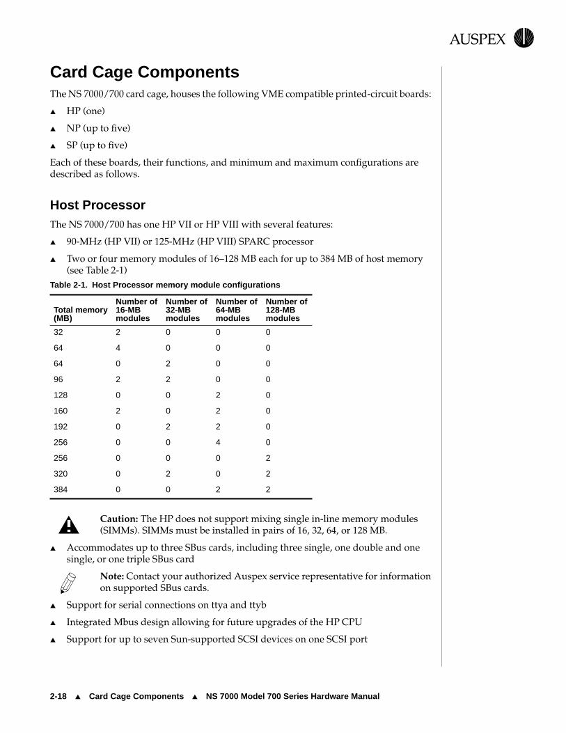
Card Cage ComponentsThe NS 7000/700 card cage, houses the following VME compatible printed-circuit boards:
▲ HP (one)
▲ NP (up to five)
▲ SP (up to five)
Each of these boards, their functions, and minimum and maximum configurations are described as follows.
Host ProcessorThe NS 7000/700 has one HP VII or HP VIII with several features:
▲ 90-MHz (HP VII) or 125-MHz (HP VIII) SPARC processor
▲ Two or four memory modules of 16–128 MB each for up to 384 MB of host memory (see Table 2-1)
Caution: The HP does not support mixing single in-line memory modules (SIMMs). SIMMs must be installed in pairs of 16, 32, 64, or 128 MB.
▲ Accommodates up to three SBus cards, including three single, one double and one single, or one triple SBus card
Note: Contact your authorized Auspex service representative for information on supported SBus cards.
▲ Support for serial connections on ttya and ttyb
▲ Integrated Mbus design allowing for future upgrades of the HP CPU
▲ Support for up to seven Sun-supported SCSI devices on one SCSI port
Table 2-1. Host Processor memory module configurations
Total memory(MB)
Number of 16-MB modules
Number of32-MB modules
Number of 64-MB modules
Number of 128-MB modules
32 2 0 0 0
64 4 0 0 0
64 0 2 0 0
96 2 2 0 0
128 0 0 2 0
160 2 0 2 0
192 0 2 2 0
256 0 0 4 0
256 0 0 0 2
320 0 2 0 2
384 0 0 2 2

NS 7000 Model 700 Series Hardware Manual ▲ Card Cage Components ▲ 2-19
USPEXA
▲ Support for tape storage devices
Figure 2-11 shows the front panel connectors on the Host Processor.
Figure 2-11. Host Processor front panel connectors
DIAG
READY RESET
RUN
DIAG
NORM
DIA
G LE
DS
SC
SI
TTYB
TTYA
SCSI port. The SCSI port supports up to seven daisy-chained SCSI devices. Refer to “Attaching a SCSI Device to the HP” on page 3-27 for a list of supported devices. Tape storage devices are also supported from the SCSI port. Refer to the Storage Peripherals Manager’s Guide for supported devices.
Reset switch. This switch resets the system processor boards without power cycling the NetServer using the main power switch.
Caution: Follow the shutdown procedures described in “Shutting Down the NetServer” on page 4-15 before you reset or power off the system.
Diagnostic LEDs. When the NetServer is running in diagnostic mode, the state of these eight LEDs represents a specific diagnostic test running on the Host Processor. When the operating system is running, the LEDs light in an oscillating pattern, the speed of which is determined by the CPU load—the slower the speed, the higher the load.
TTYB serial port. TTYB is available for connecting a modem or other serial device.
TTYA serial port. TTYA supports the console terminal. Refer to “Connecting the System Console to the Server” on page 3-10.
SBus ports. The Host Processor has three SBus ports: two masters and one slave. The HP supports three single, one double and one single, or one triple SBus board. Tape storage devices are also supported from the SBus port. Refer to the Storage Peripherals Manager’s Guide for supported devices. For information on compatible SBus boards, contact your authorized Auspex service representative.
Status indicator LEDs. The DIAG LED lights indicating the system is performing power on self tests. The READY LED lights indicating the system successfully completes self tests.
Diagnostic switch. Set this switch to the NORM position before you power on the NetServer. Setting this switch to DIAG puts the NetServer in diagnostic mode automatically after you power on or reset the system. (Provided for authorized service personnel only.)
Fuse. Refer to “Exabyte Tape Maintenance” on page 5-8 for more information.

2-20 ▲ Card Cage Components ▲ NS 7000 Model 700 Series Hardware Manual
USPEXA
Network ProcessorThe NS 7000/700 uses one to five NP II, NP III, or NP IV boards, each supporting either Ethernet, FDDI, ATM, or any combinations of these interfaces.
Note: ATM and 100Base-T Ethernet require optional software. Refer to the documentation provided on the Auspex Premier Software Series CD-ROM for more information.
Table 2-2 shows an example of the supported network interfaces for the NP boards.
Table 2-2. Supported network interfaces
Each NP has 64–256 MB of memory for protocol processing, file processing, and I/O cache memory. The NP III and NP IV have four or eight SIMMs of either 16 MB or 32 MB each. Memory must be installed in groups of four SIMMs of the same capacity. The NP II has one or two memory modules of either 64 MB or 128 MB each. Refer to Table 2-3 for supported memory configurations.
Number and type of interfaces supported NP II NP III NP IV
2-Enet Y Y Y
6-Enet Y Y Y
1 FDDI, 4-Enet Y Y Y
1 ATM, 4-Enet Y Y Y
2 ATM, 2-Enet Y Y Y
1 100BT, 4-Enet Y Y Y
2 100BT, 2-Enet Y Y Y
3 FDDI N Y Y
3 ATM N Y Y
3 Half-duplex 100BT N Y Y
3 Full-duplex 100BT N Y Y
2 Full-duplex 100BT, 2-Enet Y Y Y
1 Full-duplex 100BT, 4-Enet Y Y Y
1 Full-duplex 100BT, 1 FDDI Y Y Y
Table 2-3. Network Processor memory configurations
NP IV/III NP II
Total memory(MB)
Number of 16-MB SIMMs
Number of 32-MB SIMMs
Number of 64-MB modules
Number of 128-MB modules
64 4 0 1 0
128 8 0 2 0
128 0 4 0 1
192 4 4 1 1
256 0 8 0 2

NS 7000 Model 700 Series Hardware Manual ▲ Card Cage Components ▲ 2-21
USPEXA
The NP III and NP IV have a VME transfer speed of up to 100 MB per second when operating in conjunction with an SP V board. The NP II has a VME transfer speed of up to 55 MB per second when operating in conjunction with either an SP IV or an SP V board.
Storage ProcessorThe NS 7000/700 uses one to five SP IV or SP V boards, each with six parallel SCSI channels for disk, tape, and CD-ROM drives. Each SP can have an optional Write Accelerator board added to enhance NFS write operations. The SP V supports the Write Accelerator II and Write Accelerator III, which have 2 and 8 MB of cache memory, respectively. The SP IV supports the Write Accelerator I, which has 1 MB of cache memory.
As an option, you can have up to two SP III-E boards, each with 10 parallel SCSI channels for disk, tape, and CD-ROM drives. The SP III-E has 1 MB of onboard memory for higher data throughput and supports the Write Accelerator I board.
The SP III-E and SP IV have a VME transfer speed of up to 55 MB per second when operating in conjunction with either an NP II, NP III, or NP IV. The SP V has a VME transfer speed of up to 100 MB per second when operating in conjunction with an NP III or NP IV.
Figure 2-12 shows a card cage configuration with network connections.
Figure 2-12. System processors
SCSI connector
Host Processor
Network Processor
Storage Processor

2-22 ▲ Processor Board Slot Assignments ▲ NS 7000 Model 700 Series Hardware Manual
USPEXA
Processor Board Slot AssignmentsThis section explains the slot assignments for each processor board. For information on configurations, refer to “Processor Board Configurations” on page 1-5.
Table 2-4 shows the slot allocations listed for each processor board.
Table 2-4. Processor board slot allocations
Caution: If you have a base cabinet with mixed expansion cabinets (that is, one NS 7000/060 expansion cabinet and one NS 7000/050 expansion cabinet), the SP III-E boards controlling the NS 7000/050 expansion cabinet are installed in slots 12 and 13. SP III-E boards must occupy higher-numbered slots than the NP boards to function properly.
If you have a base cabinet with one expansion cabinet
▲ The Host Processor board is installed in slots 1 and 2.
▲ Starting in slot 5, Network Processor boards are installed (up to five).
▲ Slot 11 is reserved for future use.
▲ Starting in slot 12, Storage Processor boards are installed (up to three).
Note: Slots 2 and 10 are not accessible individually. Slots 5, 6, 7, and 8 are double-width slots. Slots 9 and 10 serve as the fifth double-width slot for NP boards.
If you have a base cabinet with two expansion cabinets
▲ The Host Processor is installed in slots 1 and 2.
▲ The fourth and fifth Storage Processor boards are installed in slots 3 and 4 (numbered SP3 and SP4 by the system software).
▲ Starting in slot 5, Network Processor boards are installed (up to five).
▲ Slot 11 is reserved for future use.
▲ Starting in slot 12, the first three Storage Processor boards are installed (numbered SP0, SP1, and SP2 by the system software).
Note: Slots 2 and 10 are not accessible individually. Slots 5, 6, 7, and 8 are double-width slots. Slots 9 and 10 serve as the fifth double-width slot for NP boards.
Slot
Processor board 1 2 3 4 5 6 7 8 9 10 11 12 13 14
Host Processor
Network Processor
Storage Processor

NS 7000 Model 700 Series Hardware Manual ▲ Power Supply Configurations ▲ 2-23
USPEXA
Power Supply ConfigurationsThis section describes the redundant and nonredundant power supply requirements for the base cabinet and NS 7000/060 expansion cabinet and the redundant configuration for the NS 7000/052 expansion cabinet.
In a redundant configuration, if one power supply fails, the remaining power supply keeps the NetServer operating. When this occurs, the failed power supply can be hot-plugged while the server is running off the remaining supply. Power supplies can also be hot-plugged when your configuration requires additional power.
Base Cabinet and NS 7000/060 Expansion CabinetThe base cabinet and NS 7000/060 expansion cabinet support up to three power supplies each. These power supplies share the power requirements of the NetServer.
Note: If you need to install or replace a power supply, contact your authorized Auspex service representative.
Table 2-5 lists the number of power supplies needed to operate the base cabinet in anonredundant state. For redundant operation, add an additional power supply.
Table 2-6 lists the number of power supplies needed to operate the NS 7000/060 expansion cabinet in nonredundant and redundant states.
Table 2-5. Base cabinet power supply configuration rules
Number of power supplies required
Number of drive racks
installed
Number of processor boards installed
3 4 5 6 7 8 9 10 11
1 1 1 1 1 2 2 2 2 2
2 1 1 1 2 2 2 2 2 2
3 1 1 2 2 2 2 2 2 2
4 1 2 2 2 2 2 2 2 2
5 2 2 2 2 2 2 2 2 2
6 2 2 2 2 2 2 2 2 2

2-24 ▲ Power Supply Configurations ▲ NS 7000 Model 700 Series Hardware Manual
USPEXA
Empty power supply slots are covered with an access panel for proper air flow and EMI reduction.
For inspection procedures and maintenance instructions for the power supplies, refer to “Redundant Power Supply Operation” in Chapter 5.
NS 7000/052 Expansion CabinetThe NS 7000/052 is configured at the factory with two or four power supplies (each pair supports an array of up to 20 drives). Two power supplies are located below the bottom drive rack (drive rack 1). They share the current demands of the drive arrays in the lower four drive racks. If one of the power supplies fail, the remaining supply keeps the system operating.
Note: Adding or replacing a power supply in the NS 7000/052 requires shutting down the NetServer.
If the upper four drive racks are installed in the expansion cabinet, two power supplies are located between drive racks 4 and 5 to provide power to the additional drive arrays (refer to Figure 2-9 on page 2-16 for power supply locations).
For more information on redundant supplies, refer to “Redundant Power Supply Operation” in Chapter 5.
Table 2-6. NS 7000/060 expansion cabinet power supply configuration rules
Number of drive racks
installed
Number of power supplies needed
Nonredundant operation
Redundant operation
1 1 2
2 1 2
3 1 2
4 1 2
5 1 2
6 1 2
7 2 3
8 2 3
9 2 3
10 2 3
11 2 3
12 2 3

NS 7000 Model 700 Series Hardware Manual ▲ About This Chapter ▲ 3-1
USPEXA
3 Installation
About This ChapterThis chapter describes installing NetServer components. It does not describe installing card cage components, such as processor boards and memory modules.
This chapter covers the following sections:
▲ Grounding the NetServer
▲ Installing the Antistatic Wrist Strap
▲ Connecting the SCSI Drive Cables from the Expansion Cabinet
▲ Connecting the System Console to the Server
▲ Connecting the NetServer to the Network
▲ Installing Drives
▲ Attaching a SCSI Device to the HP
Note: The NetServer is configured at the factory to match your order. Additional processor boards, processor board memory, and drives are available as optional equipment. If you are adding or replacing a board or module in your NetServer, contact your authorized Auspex service representative for assistance.
Caution: Do not cut the black or white tie-wraps. The black and white tie-wraps hold bundles of cables together and keep them out of the way during system operation and drive installation. Throughout the procedures in this chapter, when you are instructed to cut tie-wraps to free needed cables or components, remember to cut only red tie-wraps.
For installation at sites with raised flooring, the base cabinet and expansion cabinet have a floor access panel that can be removed, allowing the NetServer cabling to pass through the hole in the floor of the cabinet. For assistance with removing the floor access panel, contact your authorized Auspex service representative.

3-2 ▲ Grounding the NetServer ▲ NS 7000 Model 700 Series Hardware Manual
USPEXA
Grounding the NetServerThis section provides instructions for grounding the base cabinet. You must plug in the power cord for each cabinet to create a ground path for the antistatic wrist strap.
Warning: The wiring at your site must provide for ground fault protection.
Tools
▲ Knife to open the packing boxes containing drives and accessories
▲ Wire cutter to cut tie-wraps (cut only red tie-wraps)
▲ 3/16-inch flat-blade screwdriver to attach the console cable
▲ 7/16-inch nut driver
▲ #2 Phillips screwdriver
1. Locate the main power switch on the PDU at the bottom of the base cabinet, and set it to OFF (O). Figure 3-1 shows the location of the switch in the base cabinet.
Caution: Use the main power switch on the PDU only. The switch at the top of each power supply should always be ON ( — ).
Figure 3-1. Main power switch (back view of base cabinet)
2. If your NetServer includes an expansion cabinet, locate the main power switch on the PDU at the bottom of the expansion cabinet. Set this switch to OFF (O). Figure 3-2 shows the location of the switch in the expansion cabinet.
Caution: Use the main power switch on the PDU only. For the NS 7000/060 expansion cabinet, the switch at the top of each power supply located should always be ON ( — ).
Main power switch
PDU

NS 7000 Model 700 Series Hardware Manual ▲ Grounding the NetServer ▲ 3-3
USPEXA
Figure 3-2. Main power switch (back view of expansion cabinet)
3. Locate the power cable for each cabinet.
On the base cabinet, the cable is hanging on the left side of the cabinet, secured with red tie-wraps. On the expansion cabinet, the cable is coiled on top of the panel covering the power supply.
4. Cut the red tie-wraps to release the power cable, and plug the appropriate end to the back of the PDU.
5. Tighten the strain relief surrounding the plug at the PDU.
6. After ensuring the power to the system is off, route each power cable to a separate grounded outlet, and plug it in. The outlet must be on a 16 amp-rated circuit for the base cabinet and the NS 7000/060 expansion cabinet, and a 20 amp-rated circuit for the NS 7000/050 expansion cabinet.
Caution: Do not power on the server at this time. You connected the power cable only to provide a ground path for the antistatic wrist strap. Do not power on the NetServer until instructed to do so later in this manual.
This concludes the procedure for grounding the NetServer. Proceed to section “Installing the Antistatic Wrist Strap” on page 3-4.
Main power switch
PDU
Strain relief

3-4 ▲ Installing the Antistatic Wrist Strap ▲ NS 7000 Model 700 Series Hardware Manual
USPEXA
Installing the Antistatic Wrist StrapThis section provides procedures for installing the antistatic wrist strap. To prevent electrostatic damage to the NetServer, always wear the antistatic wrist strap when you come in contact with electrostatic-sensitive equipment.
Note: The wrist strap cannot prevent electrostatic damage to system components until the power cable is plugged into a grounded power receptacle.
The base cabinet and expansion cabinets have two wrist strap jacks each, one on theleft chassis frame rail inside the upper front door and one on the left chassis frame rail inside the back door.
One wrist strap is provided with each cabinet. On the base cabinet, the strap is attached to the back jack. On the expansion cabinet, the strap is attached to the front jack.
1. Cut the red tie-wraps holding the wrist strap to the chassis frame rail hook.
2. To use the wrist strap, remove the strap from the hook and slide it around your wrist, as shown in Figure 3-3.
Note: When you are not using the wrist strap, remember to hang it on the hook.
3. As you move between the front and back of the system, you can unplug the wrist strap from one jack into another.
Figure 3-3. Antistatic wrist strap
Wrist strap Chassis frame rail
Card cage
Wrist strap jack

NS 7000 Model 700 Series Hardware Manual ▲ Connecting the SCSI Drive Cables from the Expansion Cabinet ▲ 3-5
USPEXA
Connecting the SCSI Drive Cables from the Expansion CabinetOptional expansion cabinets are available from Auspex. This section describes how to connect the cables to the Storage Processor boards in the base cabinet and how to route the SCSI cables from each expansion cabinet to the base cabinet. The procedure assumes that the base cabinet and the expansion cabinet are properly connected.
Note: If you need to connect an expansion cabinet to the base cabinet, contact your authorized Auspex service representative.
The SCSI cables from the NS 7000/060 expansion cabinet must be connected to an SP IV or SP V board in the base cabinet. The SCSI cables from the NS 7000/050 expansion cabinet must be connected to an SP III-E board.
NS 7000/060 Expansion Cabinet SCSI CablingThe NS 7000/060 expansion cabinet is shipped with twelve SCSI cables installed inside the cabinet. The following procedure describes how to connect the SCSI cables to the SP IV or SP V board in the base cabinet. The procedure assumes that the base cabinet and the expansion cabinet are properly connected.
To connect SCSI cables to an SP IV or SP V board in the base cabinet
1. Locate the SCSI drive cables tie-wrapped to the left side of the expansion cabinet inside the back door.
2. Cut the red tie-wraps securing the cables.
3. Route the free end of each SCSI cable through the open side of the expansion cabinet and into the open side of the base cabinet.
4. Gently pull the cable in through the open side of the base cabinet, being careful to avoid bending it in a tight radius. Leave a small amount of slack in the cable inside the expansion cabinet.
5. Connect each cable to the SP IV or SP V connector indicated on the label affixed to the cable. Table 3-1 lists all the cable connections to the SP boards from drive racks in the first and second NS 7000/060 expansion cabinets.
Refer to Appendix A for the drive rack numbering scheme. For more information on connecting SCSI cables, refer to Appendix B.
Note: Verify that the SCSI cable has been routed from the proper expansion cabinet. The first expansion cabinet is to the right of the base cabinet when viewed from the back. The second expansion cabinet is to the left.
This concludes the procedure for connecting SCSI cables to an SP IV or SP V board in the base cabinet.

3-6 ▲ Connecting the SCSI Drive Cables from the Expansion Cabinet ▲ NS 7000 Model 700 Series Hardware Manual
USPEXA
Figure 3-4 shows an NS 7000/060 expansion cabinet connected to an NS 7000/700 base cabinet.
* SP0, SP1, SP2, SP3, and SP4 are located in card cage slots 12, 13, 14, 3, and 4, respectively.
Table 3-1. Drive rack SCSI cable connections
NetServer cabinet
SCSI rack (bank)
SCSI cable connection: end 1
Storage Processor position in card cage*
Connection on Storage Processor board
SCSI cable connection: end 2
First expansion cabinet
1 Bank 1 Second SP (SP1) J1 SP1J1/Bank1
2 Bank 2 Second SP (SP1) J2 SP1J2/Bank2
3 Bank 3 Second SP (SP1) J3 SP1J3/Bank3
4 Bank 4 Second SP (SP1) J4 SP1J4/Bank4
5 Bank 5 Second SP (SP1) J5 SP1J5/Bank5
6 Bank 6 Second SP (SP1) J6 SP1J6/Bank6
7 Bank 7 Third SP (SP2) J1 SP2J1/Bank7
8 Bank 8 Third SP (SP2) J2 SP2J2/Bank8
9 Bank 9 Third SP (SP2) J3 SP2J3/Bank9
10 Bank 10 Third SP (SP2) J4 SP2J4/Bank10
11 Bank 11 Third SP (SP2) J5 SP2J5/Bank11
12 Bank 12 Third SP (SP2) J6 SP2J6/Bank12
Second expansion cabinet
1 Bank 1 Fourth SP (SP3) J1 SP3J1/Bank1
2 Bank 2 Fourth SP (SP3) J2 SP3J2/Bank2
3 Bank 3 Fourth SP (SP3) J3 SP3J3/Bank1
4 Bank 4 Fourth SP (SP3) J4 SP3J4/Bank4
5 Bank 5 Fourth SP (SP3) J5 SP3J5/Bank5
6 Bank 6 Fourth SP (SP3) J6 SP3J6/Bank6
7 Bank 7 Fifth SP (SP4) J1 SP4J1/Bank7
8 Bank 8 Fifth SP (SP4) J2 SP4J2/Bank8
9 Bank 9 Fifth SP (SP4) J3 SP4J3/Bank9
10 Bank 10 Fifth SP (SP4) J4 SP4J4/Bank10
11 Bank 11 Fifth SP (SP4) J5 SP4J5/Bank11
12 Bank 12 Fifth SP (SP4) J6 SP4J6/Bank12

NS 7000 Model 700 Series Hardware Manual ▲ Connecting the SCSI Drive Cables from the Expansion Cabinet ▲ 3-7
USPEXA
Figure 3-4. Back view of connected cabinets

3-8 ▲ Connecting the SCSI Drive Cables from the Expansion Cabinet ▲ NS 7000 Model 700 Series Hardware Manual
USPEXA
NS 7000/050 Expansion Cabinet SCSI CablingThe NS 7000/050 expansion cabinet is shipped with twelve SCSI cables installed inside the cabinet. The following procedure describes how to connect the SCSI cables to the SP III-E board in the base cabinet. The procedure assumes that the base cabinet and the expansion cabinet are properly connected.
Note: The NS 7000/050 expansion cabinet must be installed to the right of the base cabinet when viewed from the back.
To connect SCSI cables to an SP III-E board in the base cabinet
1. Locate the SCSI drive cables tie-wrapped to the left side of the expansion cabinet inside the back door.
2. Cut the red tie-wraps securing the cables.
3. Route the free end of each SCSI cable through the open side of the expansion cabinet and into the open side of the base cabinet.
4. Gently pull the cable in through the open side of the base cabinet, being careful to avoid bending it in a tight radius. Leave a small amount of slack in the cable inside the expansion cabinet.
5. Connect each cable to the SP III-E connector indicated on the label affixed to the cable. Table 3-2 lists all the cable connections to the SP III-E board from the drive racks in the NS 7000/050 expansion cabinet.
Refer to Appendix A for the drive rack numbering scheme. For more information on connecting SCSI cables, refer to Appendix B.
Note: Verify that the SCSI cable has been routed from the proper expansion cabinet. The first expansion cabinet is to the right of the base cabinet when viewed from the back. The second expansion cabinet is to the left.
This concludes the procedure for connecting SCSI cables to an SP III-E board in the base cabinet.
Table 3-2. Connecting SCSI cables from the NS 7000/050
Drive rack connector on the
NS 7000/050
Storage Processor III-E
connector*
Rack 1 J0 SP1 J1
Rack 1 J2 SP1 J2
Rack 1 J4 SP1 J3
Rack 2 J0 SP1 J4
Rack 2 J2 SP1 J5
Rack 2 J4 SP1 J6
Rack 5 J0 SP2 J1
Rack 5 J2 SP2 J2
Rack 5 J4 SP2 J3
Rack 6 J0 SP2 J4

NS 7000 Model 700 Series Hardware Manual ▲ Connecting the SCSI Drive Cables from the Expansion Cabinet ▲ 3-9
USPEXA
Note: Drive racks 3, 4, 7, and 8 are not listed in the table because they are daisy-chained from racks 1, 2, 5, and 6, respectively, and are not connected directly to an SP III-E board. Refer to Appendix B for more information.
* SP1 and SP2 are located in slots 13 and 14,respectively.
Rack 6 J2 SP2 J5
Rack 6 J4 SP2 J6
Table 3-2. Connecting SCSI cables from the NS 7000/050 (Continued)
Drive rack connector on the
NS 7000/050
Storage Processor III-E
connector*

3-10 ▲ Connecting the System Console to the Server ▲ NS 7000 Model 700 Series Hardware Manual
USPEXA
Connecting the System Console to the ServerThis section explains how to connect the system console to the NetServer. Auspex provides an ANSI-compatible DEC VT510 terminal with each NetServer for use as a system console. If you wish to use another type of terminal as a console, call your authorized Auspex service representative for information.
Table 3-3 lists the key setup parameters necessary to configure any console for use with the NetServer. The setup parameters are preconfigured for consoles purchased from Auspex.
To connect the DEC VT510 console to the server
1. Place the packing box containing the console near the server.
2. Remove the console and its components from the packing box.
3. Attach the keyboard and power cable to the console, as described in the console’s user manual.
Caution: Do not power on the console at this time.
4. Remove the console cable from its packing box.
5. Open the back door of the base cabinet, and put on the antistatic wrist strap.
6. Route one end of the console cable through the opening in the PDU at the back of the cabinet, as shown in Figure 3-5.
Note: In raised-floor environments, the cable can be routed through the floor panel of the server. Contact your authorized Auspex service representative for assistance.
Table 3-3. Console setup parameter values
Parameter Value
Handshake XON/XOFF
Mode Full duplex
Data bits 8
Stop bit 1
Parity bit None
Modem port 9600 bps
Compatible mode ANSI

NS 7000 Model 700 Series Hardware Manual ▲ Connecting the System Console to the Server ▲ 3-11
USPEXA
Figure 3-5. Routing cables to the NetServer
7. Attach the console cable to the connector on the HP labeled TTYA (serial port A).
8. Hang up the wrist strap, and close the back door of the base cabinet.
9. Attach the free end of the console cable to the left connector at the back of the console labeled Comm 1.
10. Make sure the console power cord is properly connected to the console, and plug it into a grounded power outlet.
Caution: Do not use the utility outlets on the back of the PDU to power peripherals such as the console unless the console can accept the same voltage as the wall receptacle. If there is a mismatch in voltage, you can damage the peripheral.
11. Power on the console.
Note: If you did not purchase your console from Auspex, you need to configure the console as described in Appendix C.
This concludes the procedure for connecting the system console to the NetServer. Proceed to the section “Connecting the NetServer to the Network” on page 3-12.
Serial port B
Serial port A
Power cable
Console cable
Network cables

3-12 ▲ Connecting the NetServer to the Network ▲ NS 7000 Model 700 Series Hardware Manual
USPEXA
Connecting the NetServer to the NetworkThis section provides instructions for connecting the NetServer to your network. It assumes the appropriate network is already installed at your site.
Note: Auspex does not supply network cables. For network cable specifications, refer to Appendix B.
The NetServer supports NFS file service through Ethernet, FDDI, and ATM networks. The FDDI networks supported are fiber dual-attach station (DAS) and both fiber and MLT-3 single-attach station (SAS). The Ethernet networks supported are 10Base-T and 100Base-T (half or full duplex). The ATM networks supported are fiber.
Note: ATM and 100Base-T require optional software (refer to the documentation provided on the Auspex Premier Software Series CD-ROM for more information on these optional products).
Connecting Network Cables to the NetServer
To connect the network cables to the NetServer base cabinet
1. Open the back door of the base cabinet.
2. Attach the antistatic wrist strap to your wrist to protect against possible static damage to the equipment.
3. Route each network cable to the back of the NetServer, being careful not to bend the cable in a tight radius (see Figure 3-5 on page 3-11).
In raised-floor environments, cables can be routed through the floor panel of the server. Contact your authorized Auspex service representative for assistance.
4. Attach each network cable to the appropriate connector on the NP boards. Leave a small amount of slack in the cable inside the cabinet.
Note: The FDDI-SAS port for a fiber connection is a single-attach station of “Type S.” Connect the FDDI-SAS only to a Type M FDDI concentrator port.
The FDDI-DAS ports are a dual-attach station. You can connect directly to the primary and secondary FDDI rings or to “Type M” ports on two concentrators in a dual-attached configuration.
Note: The ATM connector uses a 155 MB-per-second multimode fiber cable with an SC-type connector. If your site uses ST-type ATM cabling, you need an ST-to-SC converter.
5. Hang up the wrist strap, and close the back door of the base cabinet.

NS 7000 Model 700 Series Hardware Manual ▲ Connecting the NetServer to the Network ▲ 3-13
USPEXA
6. After powering on the NetServer as described in Chapter 4, you can test the connection between the NetServer and the network by running NSconfig.
Note: For more information on NSconfig, refer to your System Manager’s Guide.
This concludes the procedure for connecting network cables to the NetServer.
Figures 3-6 through 3-13 show cable connections to network interfaces on the processor boards.
Figure 3-6. Connection to 10Base-T Ethernet ports
Ethernet connectors

3-14 ▲ Connecting the NetServer to the Network ▲ NS 7000 Model 700 Series Hardware Manual
USPEXA
Figure 3-7. Connection to 100Base-T Ethernet ports
Figure 3-8. Connection to full-duplex 100Base-T ports
PORT
PORT
2
100Base-T Ethernet connectors
1
Full-duplex 100Base-T Ethernet connectors
PORT
2
PORT
1

NS 7000 Model 700 Series Hardware Manual ▲ Connecting the NetServer to the Network ▲ 3-15
USPEXA
Figure 3-9. Connection to FDDI (fiber) ports
Figure 3-10. Connection to FDDI (MLT-3) ports
FDDI connectors
MLT-3 connectors

3-16 ▲ Connecting the NetServer to the Network ▲ NS 7000 Model 700 Series Hardware Manual
USPEXA
Figure 3-11. Connection to ATM (fiber) ports
ATM (fiber) connectors
RT
RT

NS 7000 Model 700 Series Hardware Manual ▲ Connecting the NetServer to the Network ▲ 3-17
USPEXA
Figure 3-12. Mixed NP network interfaces
NP (FDDI-SAS/Full-Duplex
100BT)
NP (Enet/Full-Duplex
100BT)
NP (Full-Duplex 100BT)
MII
MII
MII
MII
MII

3-18 ▲ Connecting the NetServer to the Network ▲ NS 7000 Model 700 Series Hardware Manual
USPEXA
Network Interface NumberingEach NetServer network interface has a unique identifier within each type of connection: 10Base-T or 100Base-T (half or full duplex) Ethernet, FDDI, and ATM. These interface numbers are used when configuring the system software. Each numbering scheme is described as follows.
10Base-T Ethernet Interfaces are numbered within the range from ae0 to aen, where 0 is the lower 10Base-T Ethernet port closest to the HP, and n is the upper 10Base-T Ethernet port farthest from the HP.
Half-duplex 100Base-T Ethernet Interfaces are numbered within the range from afe0 to afen, where 0 is the lower 100Base-T Ethernet port closest to the HP, and n is the upper 100Base-T Ethernet port farthest from the HP.
Full-duplex 100Base-T Ethernet Interfaces are numbered within the range from ahme0 to ahmen, where 0 is the lower 100Base-T Full Duplex port closest to the HP, and n is the upper 100Base-T Full Duplex port farthest from the HP.
FDDI Interfaces are numbered within the range from afddi0 to afddin, where 0 is the lower FDDI port closest to the HP, and n is the upper FDDI port farthest from the HP.
Note: In DAS configurations, only one port is assigned an interface number although two ports exist on the FDDI-DAS board.
ATM Each port has two kinds of interfaces: one primary interface (called the FORE IP interface) and four virtual interfaces. The primary interfaces are numbered within the range from afa0 to afan, where 0 is the lower ATM port closest to the HP, and n is the upper ATM port farthest from the HP. The virtual interfaces are numbered within the range from aqa0 to aqa7.
Figure 3-13 shows an example of how network interfaces are numbered.

NS 7000 Model 700 Series Hardware Manual ▲ Connecting the NetServer to the Network ▲ 3-19
USPEXA
Figure 3-13. Mixed NP interface numbering
NP (FDDI-SAS/Full-duplex
100BT)
NP (Enet/Full-duplex
100BT)
NP (Full-duplex 100BT)
MII
MII
MII
MII
MII
Label location
Label location
afddi0
afddi0
ahme0
ae0
ae1
ahme1
ahme2
ahme3

3-20 ▲ Connecting the NetServer to the Network ▲ NS 7000 Model 700 Series Hardware Manual
USPEXA
Ethernet AddressesEach Ethernet port has a unique Ethernet address assigned at Auspex. At the top of each installed NP with Ethernet ports is a label that gives the serial number of the board and Ethernet address for the interface located at the bottom of the board (for example, ahme0 in Figure 3-13). This address ends with 0. This numbering scheme continues up to the top interface, which has a network address ending with 3.
All Auspex Ethernet addresses start with 00:00:3c.
Table 3-4 lists an example of network addresses for the full-duplex 100Base-T Ethernet interface in Figure 3-13.
* This address appears on the label
Table 3-4. Ethernet address numbering scheme for full-duplex 100Base-T
Interface number Network address
ahme3 00:00:3c:99:99:03
ahme2 00:00:3c:99:99:02
ahme1 00:00:3c:99:99:01
ahme0 00:00:3c:99:99:0*

NS 7000 Model 700 Series Hardware Manual ▲ Installing Drives ▲ 3-21
USPEXA
Installing DrivesThe NetServer disk, tape, and CD-ROM drives are shipped separately. They must be unpacked and installed into the NetServer drive racks before you can use the system. This section describes how to install disks shipped with your NetServer. For instructions on removing drives and information on possible drive configurations, refer to Appendix A. For information on installing a DLT4000 tape drive, which requires a specially designed drive rack, refer to the Storage Peripherals Manager’s Guide.
Note: The NetServer supports up to 210 disk, tape, or CD-ROM drives. It also supports tape storage devices off the HP and Storage Processor. Drive slot 0 in the base cabinet is reserved for the root disk drive, which contains the server’s operating system software.
The drive slot numbering starts at the top front rack in the base cabinet and NS 7000/060 expansion cabinet. In the NS 7000/050, the drive slot numbering is reversed, starting from the bottom rack. Figures 3-14 through 3-16 illustrate slot numbering.
You received a set of labels to attach to any drives that you might install in your NetServer. Write down the slot number of the drive, as recognized by the system software, on each label (see “Drive Slot Numbering” for more information). Put the extra labels away in a safe place. You will need them when you expand your system.
Caution: To preserve data integrity, make sure that the system is powered off throughout this procedure.
For the NS 7000/050 expansion cabinet, the drives you received have been configured with the correct SCSI ID for the designated slot’s rack. The drive slot number appears on the label taped to the drive. Refer to “Verifying and Changing Jumper Settings” in Appendix A if you decide to install a drive in a rack other than the one designated. It is not necessary to set the SCSI ID for drives in the base cabinet or the NS 7000/060 expansion cabinet.
Drive Slot NumberingThe system software recognizes slot numbers as a continuation from the base cabinet to the first expansion cabinet and then to the second expansion cabinet.
The slot numbering in the first and second expansion cabinets vary, depending on the type of expansion cabinet installed. The NS 7000/060 expansion cabinet supports up to 84 drives. The NS 7000/050 expansion cabinet supports up to 40 drives.
Figure 3-14 shows the slot and drive rack numbering for the base cabinet. Figure 3-15 shows the slot and drive rack numbering for a standalone NS 7000/060 expansion cabinet. Figure 3-16 shows the slot and drive rack numbering for a standalone NS 7000/050 expansion cabinet.

3-22 ▲ Installing Drives ▲ NS 7000 Model 700 Series Hardware Manual
USPEXA
Figure 3-14. Base cabinet drive slot numbering
Slot 34
Slot 33
Slot 32
Slot 31
Slot 30
Slot 29
Slot 28
Slot 41
Slot 40
Slot 39
Slot 38
Slot 37
Slot 36
Slot 35
Drive rack 5
Drive rack 6
Drive rack 1
Drive rack 2
Drive rack 3
Drive rack 4
Front Back
Card cage Card cage
Slot 6
Slot 5
Slot 4
Slot 3
Slot 2
Slot 1
Slot 0
Slot 13
Slot 12
Slot 11
Slot 10
Slot 9
Slot 8
Slot 7
Slot 20
Slot 19
Slot 18
Slot 17
Slot 16
Slot 15
Slot 14
Slot 27
Slot 26
Slot 25
Slot 24
Slot 23
Slot 22
Slot 21

NS 7000 Model 700 Series Hardware Manual ▲ Installing Drives ▲ 3-23
USPEXA
Figure 3-15. NS 7000/060 expansion cabinet drive slot numbering
Slot 7
Slot 6
Slot 5
Slot 4
Slot 3
Slot 2
Slot 1
Slot 14
Slot 13
Slot 12
Slot 11
Slot 10
Slot 9
Slot 8
Slot 21
Slot 20
Slot 19
Slot 18
Slot 17
Slot 16
Slot 15
Slot 28
Slot 27
Slot 26
Slot 25
Slot 24
Slot 23
Slot 22
Slot 49
Slot 48
Slot 47
Slot 46
Slot 45
Slot 44
Slot 43
Slot 56
Slot 55
Slot 54
Slot 53
Slot 52
Slot 51
Slot 50
Slot 63
Slot 62
Slot 61
Slot 60
Slot 59
Slot 58
Slot 57
Slot 70
Slot 69
Slot 68
Slot 67
Slot 66
Slot 65
Slot 64
Slot 35
Slot 34
Slot 33
Slot 32
Slot 31
Slot 30
Slot 29
Slot 42
Slot 41
Slot 40
Slot 39
Slot 38
Slot 37
Slot 36
Slot 77
Slot 76
Slot 75
Slot 74
Slot 73
Slot 72
Slot 71
Slot 84
Slot 83
Slot 82
Slot 81
Slot 80
Slot 79
Slot 78
Drive rack 5
Drive rack 6
Drive rack 11
Drive rack 12
Drive rack 1
Drive rack 2
Drive rack 3
Drive rack 4
Drive rack 7
Drive rack 8
Drive rack 9
Drive rack 10
Front Back

3-24 ▲ Installing Drives ▲ NS 7000 Model 700 Series Hardware Manual
USPEXA
Figure 3-16. NS 7000/050 expansion cabinet drive slot numbering
Using addition, it is a simple process to determine the proper slot number recognized by the system software. Refer to the following examples:
Example 1
If a drive is in slot 54 of the first NS 7000/060 expansion cabinet, then the slot number recognized by the system software is equal to that slot number (54) plus the last slot number in the base cabinet (41). The system software recognizes the drive in slot 95 (54+41).
Example 2
If a drive is in slot 54 of the second NS 7000/060 expansion cabinet and the first expansion cabinet is also an NS 7000/060, then the slot number recognized by the system software is equal to that slot number (54) plus the total number of slots in the first expansion cabinet (84) and the last slot number in the base cabinet (41). The drive is in slot 179 (54+84+41).
Slot 36
Slot 37
Slot 38
Slot 39
Slot 40
Slot 31
Slot 32
Slot 33
Slot 34
Slot 35
Slot 26
Slot 27
Slot 28
Slot 29
Slot 30
Slot 21
Slot 22
Slot 23
Slot 24
Slot 25
Drive rack 8
Drive rack 7
Drive rack 6
Drive rack 5
Drive rack 4
Drive rack 3
Drive rack 2
Drive rack 1
Slot 16
Slot 17
Slot 18
Slot 19
Slot 20
Slot 11
Slot 12
Slot 13
Slot 14
Slot 15
Slot 6
Slot 7
Slot 8
Slot 9
Slot 10
Slot 1
Slot 2
Slot 3
Slot 4
Slot 5

NS 7000 Model 700 Series Hardware Manual ▲ Installing Drives ▲ 3-25
USPEXA
Example 3
If a drive is in slot 54 of the second NS 7000/060 expansion cabinet and the first expansion cabinet is an NS 7000/050, then the slot number recognized by the system software is equal to that slot number (54) plus the total number of slots in the first expansion cabinet (40) and the last slot number in the base cabinet (41). The drive is in slot 135 (54+40+41).
Installing a DriveCaution: The procedures in this section assume that the NetServer is powered off. If you want to remove or install a drive while the operating system is running, refer to the System Manager’s Guide.
To install drives in the NetServer
1. Place the drive packaging within easy reach of the NetServer cabinet in which the drives will be installed.
2. Plug the antistatic wrist strap into the jack location on the front chassis frame, and wear the wrist strap to protect against electrostatic damage to the drives.
3. Use a knife to open the box carefully. Drives are packed in foam slots, in an antistatic wrapping.
4. Open the proper door of the NetServer to expose the drive rack slots.
Note: The slots for the drives you ordered are empty. These unused slots are covered with filler panels, which are removed when the drives are installed.
5. Remove the disk drive from its antistatic wrapping. The disk drive has a label located at the front of the drive carrier.
6. Place the drive into the upper left slot of the base cabinet (slot 0) with the latch button toward the top of the drive carrier.
7. Holding the drive by the handle and cradling it with your other hand, gently slide it into the slot until the small latch button on the top of the drive carrier clicks into the hole in the drive slot. If this latch button obstructs the drive from sliding into the slot, depress the button at the top of the drive handle to retract the button and complete the installation.
Caution: Do not slam drives into the slots. Slamming the drives into the slots can cause damage to the drives and connectors.
Refer to Figure 3-17 for an example of installing a drive.

3-26 ▲ Installing Drives ▲ NS 7000 Model 700 Series Hardware Manual
USPEXA
Figure 3-17. Installing a drive
Drives install in only one direction. If the drive you are installing does not slide in easily and the latch does not click into place, remove the drive and try again. Make sure the drive is in the correct position with the latch button at the top of the handle.
8. Install the remaining drives in their slots. Use the labels provided with your cabinet to write down the drive slot number of the drives, as recognized by the system software.
Recommendation: For optimum performance in the NS 7000/050 expansion cabinet, tape drives should be installed in drive slots assigned a SCSI ID of 1 (refer to Figure A-9 on page A-10).
This concludes the procedure for installing drives in your NetServer. If you wish to attach a SCSI device to your NetServer, proceed to the section “Attaching a SCSI Device to the HP” on page 3-27.

NS 7000 Model 700 Series Hardware Manual ▲ Attaching a SCSI Device to the HP ▲ 3-27
USPEXA
Attaching a SCSI Device to the HPThis section describes how to attach a SCSI device to the NetServer. The SCSI port on a HP supports the standard SunOS device drivers. You can attach seven Sun-supported SCSI devices to this port, which includes four disk drives, two tape drives, and one CD-ROM drive, and tape storage devices (refer to the Storage Peripherals Manager’s Guide for more information).
Note: Devices attached to the HP SCSI port cannot be used as boot devices. Only Auspex devices attached to a Storage Processor are bootable devices. Auspex does not supply a SCSI cable for the HP SCSI port.
You must set the appropriate SCSI ID for each device attached to the HP, or the system cannot recognize the device. The SCSI IDs that you can use are listed in Table 3-5. Be sure that each device has a unique ID.
Follow this procedure to connect a SCSI device:
1. If your system is running, follow the procedures in “Shutting Down the NetServer” on page 4-15 to halt the server’s operation.
2. Open the back door of the server, and put on the antistatic wrist strap.
3. Verify that the device being attached has the correct SCSI ID.
4. Connect one end of the SCSI cable to the SCSI device, following the directions in the third-party vendor documentation for the device.
5. Route the free end of the cable through the opening in the PDU at the back of the server (see Figure 3-5 on page 3-11).
6. Connect the free end of the SCSI cable to the connector on the HP labeled SCSI (see Figure 2-11 on page 2-19).
7. Hang up the wrist strap, and close the back door of the server.
This concludes the procedure for adding SCSI devices to the HP.
Table 3-5. HP SCSI IDs and device names
Device SCSI IDDevice name
Disk 0 3 sd0
Disk 1 1 sd1
Disk 2 2 sd2
Disk 3 0 sd3
Tape 0 4 rst0
Tape 1 5 rst1
CD-ROM 0 6 sr0


NS 7000 Model 700 Series Hardware Manual ▲ About This Chapter ▲ 4-1
USPEXA
4 Power On and Shut Down
About This ChapterThis chapter describes powering on and shutting down the server, and describes the LED status indicators on the HP and NP boards.
This chapter covers the following sections:
▲ Powering On the NetServer
▲ Power-On Self Test and Boot Sequence
▲ Processor Board LED Displays
4-2 ▲ Powering On the NetServer ▲ NS 7000 Model 700 Series Hardware Manual
USPEXA
Powering On the NetServerCaution: Never cover the cooling vents on top of the NetServer. Covering the vents causes the NetServer to overheat and damages the server.
1. Verify the diagnostic switch on the HP is set to NORM.
The diagnostic switch is the lower of the two switches located on the front panel of the HP. Push this switch down to set it to NORM (see Figure 2-11 on page 2-19).
2. Make sure the main power switch on the base and each expansion cabinet’s PDU is set to OFF (O) (see Figure 3-1 on page 3-2).
Caution: Use the main power switch on the PDU only.
In the NetServer, the switch located at the top of each power supply located at the front of the cabinet should always be turned to ON ( — ).
3. Close the doors on the base and expansion cabinets.
4. Power up the console terminal.
5. Power on each expansion cabinet by setting its power switch to ON ( I ).
6. Power on each tape storage device, if present, by setting its power switch to ON ( I ).
7. Power on the base cabinet by setting its main power switch to ON ( I ).
Recommendation: Auspex recommends that you power on the expansion cabinets before you power on the base cabinet. If you power on the base cabinet first, power on the expansion cabinets within 10–15 seconds after powering on the base cabinet.
After powering on the NetServer, it runs a series of self tests and displays the results of these tests on the console screen. For a list of the power-on self tests and messages, refer to “Power-On Self Test and Boot Sequence” on page 4-3.
This concludes the procedure for powering on the NetServer.

NS 7000 Model 700 Series Hardware Manual ▲ Power-On Self Test and Boot Sequence ▲ 4-3
USPEXA
Power-On Self Test and Boot SequenceAt power on, the NetServer performs a series of WarmStart self tests. A WarmStart bypasses lengthy power-on board-level hardware and memory test procedures, speeding up the overall boot time for the system. For information on additional boot options after the initial NetServer power on, refer to the System Manager’s Guide.
If all tests pass, within 30 seconds after full power on you should see messages similar to the following on the system console:
IDPROM checksum test.
SPARC Processor (10-0107) Boot PROM Selftest.
POST RAM (Clear)Setup MMU tableCopying PROM Data to RAM
EPROM Checksum TestSys Control Register TestSW Interrupt 1 (level 1) TestSW Interrupt 2 (level 6) TestMPC Register TestECC Valid Access TestTimer 0 Interrupt (level 10) TestTimer 1 Interrupt (level 14) TestCommand Ready Interrupt TestMMU PTE Reference Bit TestMMU PTE Modified Bit TestMMU PTE Valid Bit TestMMU PTE Access Bit TestMMU TLB TestMMU Data Access Trap TestMMU Probe TestCache Data RAM TestCache Tag RAM TestCache Write Miss TestCache Write Hit TestNVRAM Battery Test GOOD BATTERY doneNVRAM Memory Test saving restoring checksum doneNVRAM Test, checksum=0x77TOD Test127 119 95 127 123 127 95 127
POST complete: Pass = 1, Errors = 0
Initialize 64 MB of Memory ... Completed.Test 0 MB of Memory (Address Test) ... Completed.
EEPROM boot device...ad(0,0,0)

4-4 ▲ Power-On Self Test and Boot Sequence ▲ NS 7000 Model 700 Series Hardware Manual
USPEXA
By default, the system then boots automatically to multiuser mode, performing a file system check during the process. The time required to boot varies with the number of disks in the system. As the system boots, you should observe the display to verify the following:
▲ The version of the operating system (in the following example, NetServer software Version 1.9).
▲ All Auspex devices (both processor boards and drives) are listed in the display, indicating that the processors and drives are detected and initialized by the system startup routines.
The following example shows the typical NetServer boot messages on the system console.
Note: In the boot message, the term IOP is used to describe the NP board.
sp - status 70 71 f0skipping SP loopback testpassed SP inquiry cmd to the boot devicepassed SP test unit ready cmd to the boot devicesp found in slot = 12Boot device: /mvic/vme/asp@6d,1180/ad@0,0:0 File and args:0x4000bootblock loadedsp - status f0skipping SP loopback testpassed SP inquiry cmd to the boot devicepassed SP test unit ready cmd to the boot devicesp - status f0skipping SP loopback testpassed SP inquiry cmd to the boot devicepassed SP test unit ready cmd to the boot deviceroot on ad0a fstype 4.2Boot: vmunixSize: 1204224+248608+557640 bytesm16u_npages_dvma = 358m16u_net_interfaces = 15VAC ENABLED in COPYBACK modeAuspex 1.9A23/SunOS 4.1.4 (AUSPEX1.OPTIMIZED) #1: Tue Nov 5 02:59:30 PST 1996Copyright 1989-1996 Auspex Systems, Inc.Copyright 1983-1994 Sun Microsystems, Inc.cpu = ASPX,Auspex SPARC Processormod0 = Ross,RT625 (mid = 2)mem = 65536K (0x4000000)avail mem = 56938496dma0 at SBus slot 1 0x400000esp0 at SBus slot 1 0x800000 pri 3zs0 at obio 0x200000 pri 12SP0 at Auspex VME slot 12SP1 at Auspex VME slot 13SP2 at Auspex VME slot 14SP3 at Auspex VME slot 3
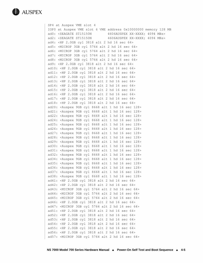
NS 7000 Model 700 Series Hardware Manual ▲ Power-On Self Test and Boot Sequence ▲ 4-5
USPEXA
SP4 at Auspex VME slot 4IOP0 at Auspex VME slot 6 VME address 0x10000000 memory 128 MBad0: <SEAGATE ST15150N 4606AUSPEX XX-XXXX; 4094 MBs>ad2: <SEAGATE ST15150N 4606AUSPEX XX-XXXX; 4094 MBs>ad4: <HP 2.0GB cyl 3818 alt 2 hd 16 sec 64>ad5: <MICROP 3GB cyl 5764 alt 2 hd 16 sec 64>ad6: <MICROP 3GB cyl 5764 alt 2 hd 16 sec 64>ad7: <MICROP 3GB cyl 5764 alt 2 hd 16 sec 64>ad8: <MICROP 3GB cyl 5764 alt 2 hd 16 sec 64>ad9: <HP 2.0GB cyl 3818 alt 2 hd 16 sec 64>ad10: <HP 2.0GB cyl 3818 alt 2 hd 16 sec 64>ad11: <HP 2.0GB cyl 3818 alt 2 hd 16 sec 64>ad12: <HP 2.0GB cyl 3818 alt 2 hd 16 sec 64>ad13: <HP 2.0GB cyl 3818 alt 2 hd 16 sec 64>ad14: <HP 2.0GB cyl 3818 alt 2 hd 16 sec 64>ad15: <HP 2.0GB cyl 3818 alt 2 hd 16 sec 64>ad16: <HP 2.0GB cyl 3818 alt 2 hd 16 sec 64>ad17: <HP 2.0GB cyl 3818 alt 2 hd 16 sec 64>ad18: <HP 2.0GB cyl 3818 alt 2 hd 16 sec 64>ad20: <Auspex 9GB cyl 8668 alt 1 hd 16 sec 128>ad21: <Auspex 9GB cyl 8668 alt 1 hd 16 sec 128>ad22: <Auspex 9GB cyl 8668 alt 1 hd 16 sec 128>ad24: <Auspex 9GB cyl 8668 alt 1 hd 16 sec 128>ad25: <Auspex 9GB cyl 8668 alt 1 hd 16 sec 128>ad26: <Auspex 9GB cyl 8668 alt 1 hd 16 sec 128>ad27: <Auspex 9GB cyl 8668 alt 1 hd 16 sec 128>ad28: <Auspex 9GB cyl 8668 alt 1 hd 16 sec 128>ad29: <Auspex 9GB cyl 8668 alt 1 hd 16 sec 128>ad30: <Auspex 9GB cyl 8668 alt 1 hd 16 sec 128>ad31: <Auspex 9GB cyl 8668 alt 1 hd 16 sec 128>ad32: <Auspex 9GB cyl 8668 alt 1 hd 16 sec 128>ad34: <Auspex 9GB cyl 8668 alt 1 hd 16 sec 128>ad35: <Auspex 9GB cyl 8668 alt 1 hd 16 sec 128>ad36: <Auspex 9GB cyl 8668 alt 1 hd 16 sec 128>ad37: <Auspex 9GB cyl 8668 alt 1 hd 16 sec 128>ad38: <Auspex 9GB cyl 8668 alt 1 hd 16 sec 128>ad41: <HP 2.0GB cyl 3818 alt 2 hd 16 sec 64>ad42: <HP 2.0GB cyl 3818 alt 2 hd 16 sec 64>ad43: <MICROP 3GB cyl 5764 alt 2 hd 16 sec 64>ad44: <MICROP 3GB cyl 5764 alt 2 hd 16 sec 64>ad45: <MICROP 3GB cyl 5764 alt 2 hd 16 sec 64>ad46: <HP 2.0GB cyl 3818 alt 2 hd 16 sec 64>ad47: <MICROP 3GB cyl 5764 alt 2 hd 16 sec 64>ad51: <HP 2.0GB cyl 3818 alt 2 hd 16 sec 64>ad52: <HP 2.0GB cyl 3818 alt 2 hd 16 sec 64>ad53: <HP 2.0GB cyl 3818 alt 2 hd 16 sec 64>ad54: <HP 2.0GB cyl 3818 alt 2 hd 16 sec 64>ad55: <HP 2.0GB cyl 3818 alt 2 hd 16 sec 64>ad56: <HP 2.0GB cyl 3818 alt 2 hd 16 sec 64>ad57: <MICROP 3GB cyl 5764 alt 2 hd 16 sec 64>

4-6 ▲ Power-On Self Test and Boot Sequence ▲ NS 7000 Model 700 Series Hardware Manual
USPEXA
ad60: <Auspex 4GB cyl 4094 alt 1 hd 16 sec 128>ad61: <Auspex 4GB cyl 4094 alt 1 hd 16 sec 128>ad62: <Auspex 4GB cyl 4094 alt 1 hd 16 sec 128>ad63: <Auspex 4GB cyl 4094 alt 1 hd 16 sec 128>ad64: <Auspex 4GB cyl 4094 alt 1 hd 16 sec 128>ad65: <Auspex 4GB cyl 4094 alt 1 hd 16 sec 128>
ad135: <Auspex 4GB cyl 4094 alt 1 hd 16 sec 128>ad136: <Auspex 4GB cyl 4094 alt 1 hd 16 sec 128>ad137: <Auspex 4GB cyl 4094 alt 1 hd 16 sec 128>ad138: <Auspex 4GB cyl 4094 alt 1 hd 16 sec 128>ad139: <Auspex 4GB cyl 4094 alt 1 hd 16 sec 128>ad140: <Auspex 4GB cyl 4094 alt 1 hd 16 sec 128>ad141: <Auspex 4GB cyl 4094 alt 1 hd 16 sec 128>ad142: <Auspex 4GB cyl 4094 alt 1 hd 16 sec 128>ad143: <Auspex 4GB cyl 4094 alt 1 hd 16 sec 128>ASPX,buf-e unit 0 at iop0 SBus slot 0ASPX,buf-e unit 1 at iop0 SBus slot 1ASPX,buf-e unit 2 at iop0 SBus slot 2ASPX,net-acc unit 0 at iop0 SBus slot 3root on ad0a fstype 4.2swap on ad0b fstype spec size 1024000Kdump on ad0b fstype spec size 1023988Kchecking root and /usr filesystems/dev/rad0a: 11163 files, 51077 used, 10538 free/dev/rad0a: (58 frags, 1310 blocks, 0.1% fragmentation)/dev/rad0g: is stable.rc.auspex: Running ax_startup (download boards and start daemons).waiting for SP1 in slot 13--status = 0x70waiting for SP1 in slot 13--status = 0x71running ax_chkdrive...ad33: <Auspex 9GB cyl 8668 alt 1 hd 16 sec 128>ax_write_cache: SP0 initializing write cache.ax_write_cache: SP3 initializing write cache.ax_write_cache: SP4 initializing write cache.ax_write_cache: SP0 enabling write cache.ax_write_cache: SP0 write cache is 'ON'.ax_write_cache: SP3 enabling write cache.ax_write_cache: SP3 write cache is 'ON'.ax_write_cache: SP4 enabling write cache.ax_write_cache: SP4 write cache is 'ON'./usr/auspex/ax_enable: AXbackup enabled/usr/auspex/ax_enable: AXraid enabledrc.auspex: Running from rc.boot (start virtual partitions).checking other filesystems/dev/rad4c: is clean./dev/rad0f: is clean./dev/rvp1024: is clean.
.
.
.

NS 7000 Model 700 Series Hardware Manual ▲ Power-On Self Test and Boot Sequence ▲ 4-7
USPEXA
/dev/rvp1032: is clean./dev/rard56a: is clean./dev/rad0d: is clean./dev/rvp1040: is clean./dev/rvp1025: is clean./dev/rad0h: is clean./dev/rvp1033: is clean./dev/rvp1041: is clean./dev/rard56b: is clean./dev/rad0e: is clean./dev/rvp1026: is clean./dev/rvp1034: is clean./dev/rard56d: is clean./dev/rvp1027: is clean./dev/rvp1035: is clean./dev/rard56e: is clean./dev/rvp1028: is clean./dev/rard56f: is clean./dev/rvp1036: is clean./dev/rard56g: is clean./dev/rvp1029: is clean./dev/rvp1037: is clean./dev/rard56h: is clean./dev/rvp1030: is clean./dev/rvp1038: is clean./dev/rvp1031: is clean./dev/rvp1039: is clean.ifconfig: ioctl (SIOCSIFDSTADDR): Invalid argumentautomatic reboot in progress...Fri Nov 8 17:02:49 PST 1996rc: mounting 4.2 and lfs file systems.checking quotas: done.rc.auspex: Running from rc (start more daemons).NIS domain name is unknownstarting rpc port mapper.starting RPC key server.starting Auspex key daemon.network interface configuration:ae0: flags=42<BROADCAST,RUNNING> inet 0.0.0.0 netmask 0 ether 0:0:3c:3:0:80ae1: flags=63<UP,BROADCAST,NOTRAILERS,RUNNING> inet 123.45.678.9 netmask ffffff00 broadcast 123.45.678.9 ether 0:0:3c:3:0:81ae2: flags=63<UP,BROADCAST,NOTRAILERS,RUNNING> inet 123.45.678.9. netmask ffffff00 broadcast 123.45.678.9 ether 0:0:3c:3:0:82ae3: flags=63<UP,BROADCAST,NOTRAILERS,RUNNING> inet 123.45.678.9 netmask ffffff00 broadcast 123.45.678.9 ether 0:0:3c:3:0:83

4-8 ▲ Power-On Self Test and Boot Sequence ▲ NS 7000 Model 700 Series Hardware Manual
USPEXA
ae4: flags=63<UP,BROADCAST,NOTRAILERS,RUNNING> inet 123.45.678.9 netmask ffffff00 broadcast 123.45.678.9 ether 0:0:3c:3:0:84ae5: flags=63<UP,BROADCAST,NOTRAILERS,RUNNING> inet 123.45.678.9 netmask ffffff00 broadcast 123.45.678.9 ether 0:0:3c:3:0:85lo0: flags=49<UP,LOOPBACK,RUNNING> inet 123.45.678.9 netmask ff000000running routing daemon.starting additional services: biod. starting system loggerstarting local daemons: auditd sendmailax_lfsdexportfs -avexported /disks/vp/lad0exported /disks/vp/lad1exported /disks/vp/lad2exported /disks/vp/lad3exported /disks/vp/lad4exported /disks/vp/lad5exported /disks/vp/lad6exported /disks/vp/lad7exported /disks/vp/lad8exported /disks/vp/lad9exported /disks/vp/lad10exported /disks/vp/lad11exported /disks/vp/lad12exported /disks/vp/lad13exported /disks/vp/lad14exported /disks/vp/lad15exported /disks/vp/lad16exported /disks/vp/lad17exported /disks/raid/normal1exported /disks/raid/normal2exported /disks/raid/normal3exported /disks/raid/normal4exported /disks/raid/normal5exported /disks/raid/normal6exported /disks/raid/normal7starting NFS daemons: nfsd ax_nfsd mountdmount -vat nfsNov 8 17:03:18 unknown syslog: ax_enable: AXraid licensedNov 8 17:03:18 unknown syslog: ax_enable: AXraid licensedNov 8 17:03:18 unknown syslog: ax_enable: AXbackup licensedNov 8 17:03:18 unknown syslog: ax_enable: AXbackup licensedrarpd: interface-pid in /tmp/rarplograrpd bootparamd statd lockd.link-editor directory cacheax_isolatedchecking for crash dump...
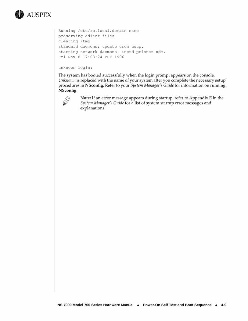
NS 7000 Model 700 Series Hardware Manual ▲ Power-On Self Test and Boot Sequence ▲ 4-9
USPEXA
Running /etc/rc.local.domain namepreserving editor filesclearing /tmpstandard daemons: update cron uucp.starting network daemons: inetd printer xdm.Fri Nov 8 17:03:24 PST 1996
unknown login:
The system has booted successfully when the login prompt appears on the console. Unknown is replaced with the name of your system after you complete the necessary setup procedures in NSconfig. Refer to your System Manager’s Guide for information on running NSconfig.
Note: If an error message appears during startup, refer to Appendix E in the System Manager’s Guide for a list of system startup error messages and explanations.

4-10 ▲ Processor Board LED Displays ▲ NS 7000 Model 700 Series Hardware Manual
USPEXA
Processor Board LED DisplaysThis section describes the LED displays on the HP and NP boards. The HP and NP have several LEDs, which represent power-on self tests and system activity. By monitoring these LEDs, you can determine if the HP is functioning properly and if you have proper network connectivity on the NP.
Host ProcessorThe HP has three LEDs:
▲ The DIAG LED lights green, indicating that the system is performing power-onself tests.
▲ The READY LED lights green after the system successfully completes self tests.
▲ The Diagnostic LEDs light green, representing a specific diagnostic test being run on the HP when the NetServer is running in diagnostic mode. When the operating system is running, the LEDs light in an oscillating pattern, the speed of which is determined by the CPU load—the slower the speed, the higher the load.
For LED locations, refer to Figure 2-11 on page 2-19.
Network ProcessorThe NP consists of network interfaces each having their own set of LED displays. The network LED functions are described as follows.
ATM LEDs
Each ATM SBus card has two LEDs:
▲ The Receive Status LED lights green when receiving data or red when there is no carrier. If the light is red, check to see if the cable is properly attached or if the other end is up and ready. The normal condition is off, meaning the device is idle and ready to receive.
▲ The Transmit Status LED lights green when transmitting data or yellow when a SONET alarm condition is declared. The SONET alarm indicates trouble with the receiving device. If the light is yellow, check to see if the cable is properly attached or if the other end is up and ready. The normal condition is off, meaning the device is idle and ready to transmit.
Figure 4-1 shows the location of the LED displays on the ATM SBus card.

NS 7000 Model 700 Series Hardware Manual ▲ Processor Board LED Displays ▲ 4-11
USPEXA
Figure 4-1. ATM (fiber) LED display
Ethernet LEDs
Each pair of 10Base-T Ethernet ports on a NP has three green LEDs:
▲ The Stat LED lights after the system has successfully booted and the card is operational.
▲ The Act B LED lights when indicating that activity is occurring through Connector B.
▲ The Act A LED lights when indicating that activity is occurring through Connector A.
Figure 4-2 shows the location of the LED displays for one pair of 10Base-T interfaces.
Figure 4-2. 10Base-T Ethernet LED display
Receive Status LED
Cable connector guide
Transmit Status LED
Port
RT
Port A
Port B
Act A LED
Act B LED
Stat LED

4-12 ▲ Processor Board LED Displays ▲ NS 7000 Model 700 Series Hardware Manual
USPEXA
FDDI-SAS LEDs
Each FDDI-SAS port has two LEDs:
▲ The Status LED lights green when the card passed internal diagnostics. The card functions properly only if it passed internal diagnostics.
▲ The RingOP LED lights green when the card is connected to the ring. If this LED is not lit, check if the cables are properly connected and you have followed the proper procedure for powering on the NetServer.
Figure 4-3 shows the location of the LEDs for the fiber FDDI-SAS port. Figure 4-4 shows the location of the LEDs for the MLT-3 FDDI-SAS port.
Figure 4-3. FDDI-SAS (fiber) LED display
Figure 4-4. FDDI-SAS (MLT-3) LED display
RingOP LED Status LED
Port
RingOP LED Status LED
Port

NS 7000 Model 700 Series Hardware Manual ▲ Processor Board LED Displays ▲ 4-13
USPEXA
FDDI-DAS LEDs
Each FDDI-DAS port has two LEDs:
▲ The STATUS LED lights green when the SBus card passed its internal diagnostics. This LED must be lit for the SBus card to function properly.
▲ The RingOP LED lights green when the card is connected to the ring. If this LED is not lit, check if the cables are properly connected and you have followed the proper procedure for powering on the NetServer.
Table 4-1 shows an example of LED states that may occur during operation.
Figure 4-5 shows the locations of the LEDs for a FDDI-DAS connection.
* RingOP A refers to the RingOP LED for port A. RingOP B refers to the RingOP LED for port B.
Table 4-1. RingOP LED indicators on the FDDI-DAS SBus card
RingOP B* - Off RingOP B - Green RingOP B - Orange
RingOP A* - Off
Ring is not operational Station is in WRAP_B, ring is operational.
Ring is not operational. The station connected to the PHY B is attempting to connect but failed.
RingOP A - Green
Station is in WRAP_A, B is not connected.
Station is in THRU mode, ring is operational.
Station is in WRAP_A. The station connected to PHY B is attempting to connect but failed.
RingOP A - Orange
Ring is not operational. The station connected to PHY A is attempting to connect but failed.
Station is in WRAP_B. The station connected to PHY A is attempting to connect but failed.
Ring is not operational. The stations connected to PHYs A and B are attempting to connect but failed.

4-14 ▲ Processor Board LED Displays ▲ NS 7000 Model 700 Series Hardware Manual
USPEXA
Figure 4-5. FDDI-DAS LED display
RingOP LED Status LED
Port B
RingOP LED Status LED
Port A
Bypass

NS 7000 Model 700 Series Hardware Manual ▲ Processor Board LED Displays ▲ 4-15
USPEXA
Shutting Down the NetServerThis section describes how to halt operation and shut down the NetServer.
To shut down the NetServer
1. At the root prompt, type the following command to halt the server’s operation:
# shutdown -lh +5 “system shutdown in 5 minutes”
where l sends the warning message to users who are logged in, h halts the HP and causes the server to enter monitor mode, +5 is the time in minutes before the NetServer operating system comes to a halt, and the text string informs users about the shutdown.
Server clients are warned that the system is about to shut down and given time to exit their applications. Other users are prevented from logging in. If you want to halt the system operation immediately, do not specify a time in the shutdown command. After the operating system comes to a halt, the monitor prompt appears on the console terminal screen:
HP>
2. Power off the server and base cabinet by setting the main power switches to OFF (O) (see Figure 3-1 on page 3-2).
This concludes the procedure for the shutting down the NetServer.


NS 7000 Model 700 Series Hardware Manual ▲ About This Chapter ▲ 5-1
USPEXA
5 Preventive Maintenance
About This ChapterThis chapter provides preventive maintenance procedures for the NetServer air filter and Exabyte tape drives. It also covers redundant power supply operation, fan trays and LEDs, and replacing the fuse on the HP.
The chapter covers the following sections:
▲ Redundant Power Supply Operation
▲ Cleaning the NetServer Air Filter
▲ Fan Trays and LEDs
▲ Exabyte Tape Maintenance
▲ Replacing the Fuse on the HP

5-2 ▲ Redundant Power Supply Operation ▲ NS 7000 Model 700 Series Hardware Manual
USPEXA
Redundant Power Supply OperationThis section describes the power-supply LEDs on the NetServer base cabinet, NS 7000/060 expansion cabinet, and NS 7000/052 expansion cabinet.
NetServer Base Cabinet and NS 7000/060 Expansion CabinetEach NetServer power supply has three LEDs. During normal operation, the AC and DC LEDs light green to indicate the system is receiving proper power. If the ALM LED lights yellow, the power supply failed. Contact your authorized Auspex service representative to replace the power supply. Figure 5-1 illustrates the power supply LEDs.
Figure 5-1. Power supply LEDs
Caution: The power switch at the top of each power supply should always be turned ON ( — ). Refer to “Shutting Down the NetServer” on page 4-15 for proper shutdown procedures.
Table 5-1 summarizes the actions required when the LEDs are on.
Table 5-1. NetServer power supply status indicators
LEDs that are on Power supply status Required action
Green LEDs only Fully operational. None.
Yellow LED only Power supply failed. Replace power supply.
AC OK
DC OK
ALM VOLT ADJ +5V +12V
+5VD - +
+12VD - +
LEDs

NS 7000 Model 700 Series Hardware Manual ▲ Redundant Power Supply Operation ▲ 5-3
USPEXA
Note: If you are running a redundant power supply configuration, the NetServer will operate normally on one power supply. However, the failed power supply should be replaced immediately to return to redundant state. For the NetServer base cabinet and NS 7000/060 expansion cabinet, a single failed power supply can be hot-plugged.
Warning: Contact your authorized Auspex service representative to replace a power supply.
NS 7000/052 Expansion CabinetThe NS 7000/052 is an NS 7000/050 expansion cabinet with redundant power supplies. Each NS 7000/052 power supply is equipped with a yellow and green LED.Figure 5-2 illustrates the NS 7000/052 redundant power supplies.
Figure 5-2. NS 7000/052 redundant power supplies and LEDs
During normal operation, the green LED on each power supply lights to indicate system is receiving AC power. The yellow LED indicates power supply failure. The malfunctioning power supply needs to be replaced immediately so the system can continue to have redundant power supplies.
Warning: Contact your authorized Auspex service representative to replace a power supply.
Table 5-2 describes NS 7000/052 power supply status.
None The power supply is not receiving AC power, or has a catastrophic failure.
Check the power cable connection and system power switch, or contact your authorized Auspex service representative.
Table 5-1. NetServer power supply status indicators
LEDs that are on Power supply status Required action
Power supplies
PON
+ 5V
ALM
+12V
LEDs PON
+ 5V
ALM
+12V

5-4 ▲ Redundant Power Supply Operation ▲ NS 7000 Model 700 Series Hardware Manual
USPEXA
Note: If you are running a redundant power supply configuration, the NetServer will operate normally on one power supply. However, the failed power supply should be replaced immediately to return to redundant state. The NetServer must be shut down to replace the power supply.
Table 5-2. NS 7000/052 power supply status indicators
LEDs Power supply status Required action
Green LED only Fully operational. None.
Yellow LED only Power supply failure. Replace power supply.
None The power supply is not receiving AC power, or has a catastrophic failure.
Check the power cable connection and system power switch, or contact your authorized Auspex service representative.

NS 7000 Model 700 Series Hardware Manual ▲ Cleaning the NetServer Air Filter ▲ 5-5
USPEXA
Cleaning the NetServer Air FilterCheck the NetServer base cabinet air filter once a month, and clean if necessary. In environments where dust and dirt accumulate (such as during reconstruction or remodeling in or near the computer room), clean the air filter more frequently.
Caution: When handling the air filter, be careful not to damage the material.
To clean the NetServer air filter
1. Put on the antistatic wrist strap.
2. Open the front door panel.
3. Remove the screws securing the EMI screen with a Phillips screwdriver.
4. Lift the screen out of the slots at the bottom of the backplane. Refer to Figure 5-3 for location of EMI screen.
.
Figure 5-3. EMI screen location
5. Slide the air filter up until it slips free from the holding brackets (see Figure 5-4).
Backplane
EMI screen

5-6 ▲ Cleaning the NetServer Air Filter ▲ NS 7000 Model 700 Series Hardware Manual
USPEXA
.
Figure 5-4. Air filter location (front view of base cabinet)
6. Vacuum the air filter thoroughly using the brush attachment of a household vacuum cleaner.
Note: Do not use a hand-held vacuum cleaner. Hand-held vacuum cleaners do not provide enough suction to clean the air filter adequately.
7. Slide the air filter back into its holder until the plastic frame is flush with the backplane.
8. Reattach the EMI screen.
9. Close the front door panel.
This concludes the procedure for cleaning the NetServer base cabinet air filter.
Backplane
Air Filter

NS 7000 Model 700 Series Hardware Manual ▲ Fan Trays and LEDs ▲ 5-7
USPEXA
Fan Trays and LEDsThis section describes the fan trays and LEDs in the NetServer.
The fans in the base cabinet are located below the backplane, behind the EMI screen (see Figure 2-4 on page 2-10). The nine fans are mounted horizontally in three fan trays (three fans per tray) and face upward toward the drive racks.
Each fan tray has an LED indicating the operating status of the fan tray. The LEDs are located on the back of the fan trays and are visible from the back of the base cabinet. During normal operation, the green LED indicates the fan tray is operating properly. The red LED indicates the fan tray needs to be replaced. Figures 5-6 and 5-7 show the locations of the fan trays and LEDs.
Figure 5-5. Fan trays (front view of base cabinet)
Figure 5-6. Fan tray LEDs (back view of base cabinet)
Backplane
Fan trays
Fan tray LEDs

5-8 ▲ Exabyte Tape Maintenance ▲ NS 7000 Model 700 Series Hardware Manual
USPEXA
Exabyte Tape MaintenanceThis section describes tape drive and media maintenance for the Exabyte 8-mm tape drive. For DLT4000 tape maintenance, refer to the Storage Peripherals Manager’s Guide.
Operating a dirty tape drive can limit performance. The drive performs excess read or write operations to recover from media errors. In harsh application environments, where excessive debris, humidity, or temperatures can affect the tape drive, regular cleaning is required. To achieve maximum performance from your tape drive and media, follow the recommendations in this section.
Caution: If you do not maintain your tape drive head and media, you risk losing valuable data.
Cleaning the Tape DrivesThe tape drive purchased with your Auspex NetServer requires regular cleaning and routine maintenance of the tape media. Clean the tape drive at least once a month or every 30 hours of use, whichever occurs first. When you purchase a NetServer with an 8-mm drive, Auspex supplies a cleaning cartridge that cleans both read and write heads of the drive. Refer to “LED Display on the Exabyte Tape Drive” on page 5-10 for more information on when to clean the tape drive. Additional cleaning cartridges are available from Exabyte at 1-800-392-2983 or from your data cartridge dealer.
Caution: Use only Exabyte cleaning cartridges. Other cleaning products, such as video cleaning cartridges, may contain abrasive materials that can permanently damage your tape drive. Do not use liquid cleaners. These products may void the warranty on your drive.
You can clean a tape drive at least 12 times using a single cleaning cartridge. To use the cleaning cartridge, insert it into the drive as you would any other tape. The cartridge automatically loads, runs for approximately 45 seconds, and ejects when done. Do not rewind the cartridge after each cleaning. If the cleaning cartridge immediately ejects after you insert it into the drive, the cartridge expired and needs to be replaced.
Maintaining the Tape MediaHandle and store the tape media as follows:
▲ Handle the tape cartridge carefully. Do not touch the tape itself.
▲ Keep the tape away from any magnetic field.
▲ Rewind each tape fully before storing it.
▲ Store the tape it in its case when not in use to protect from dust and debris.
▲ Retension the tape if it frequently generates errors, if it has been stored for a long time, or if it has been handled roughly.
Caution: Use only digital data-grade tapes.

NS 7000 Model 700 Series Hardware Manual ▲ Exabyte Tape Maintenance ▲ 5-9
USPEXA
Note: Refer to the manufacturer’s guidelines for the life expectancy of the tape media.
Displaying Tape StatisticsThis section describes how to use the ax_tapestats command to display and print tape statistics.
Statistics displayed are as follows:
▲ Number of kilobytes of space remaining on the tape
▲ Number of correctable ECC errors since the last time statistics were reset
▲ Number of kilobytes written to the tape since the last time the statistics were reset
To display the statistics, enter the command name followed by the name of the tape drive at the shell prompt:
# ax_tapestats tapename
The system displays the statistics in the format:
nnnnnKB remaining, mm ecc errors, xxxxxKB transferred
where nnnnn, mm, and xxxxx are numerical values.
The statistics reset to zero when the tape is changed, unloaded, or rewound. Statistics also reset to zero when a program starts reading from the tape after it has already written to the tape or when it starts writing to the tape after it has been read.
A high number of ECC errors increases the number of tape drive rewrites on a given tape. Tape rewrites that occur because of ECC errors mean a loss of tape capacity because the tape is not backspaced before the rewrite.
Recommendation: Auspex recommends changing the tape cartridge if the number of ECC errors reaches 10 percent or 12 ECC errors per megabyte of data transferred. Use Exabyte tapes only. Other tapes leave excessive debris in the drive and show an increase in ECC errors early in their useful life.
The tape media is certified up to 500 passes from end to end. If the drive uses smaller portions of the tape, such as during tape rewrites because of debris-induced errors, the number of passes might decrease.
NetServers independently monitor tape errors. If a NetServer detects excessive ECC errors, it prints the following messages:
xxxx recovered errors per MB transferred.The tape may be wearing out or the head may need cleaning.
For more information regarding Exabyte tapes, refer to the System Manager’s Guide.

5-10 ▲ Exabyte Tape Maintenance ▲ NS 7000 Model 700 Series Hardware Manual
USPEXA
LED Display on the Exabyte Tape DriveThe tape drive uses three LEDs to indicate operating conditions. The three LEDs are located on the left side of the front panel. Table 5-3 shows important combinations of LED conditions that may occur during operation. You can use these LED combinations to determine the tape drive’s operating state, as follows:
▲ The top LED lights when the tape drive has an error or needs cleaning.
▲ The middle LED lights when SCSI bus activity is occurring and if the tape is in compressed or uncompressed format.
▲ The bottom LED lights when a cartridge is loaded. When this LED flashes, drive activity is occurring.
Note: After 30 hours of use, the tape drive needs cleaning. This is indicated by all three LEDs flashing simultaneously. After the tape drive is cleaned, the LEDs resume normal operation.
Key for Table 5-3:
* The amber LED indicates compressed format. The green LED indicates uncompressed format.
Table 5-3. Important LED combinations on the tape drive
Ready—no tape loaded
Ready—tape
loaded
Normal tape
position
High-speed tape
motion
SCSI bus
reset ErrorTime
to clean
Cleaning tape
loaded
Top LED(errors)
o o o o • *
slow
*
fast
o
Middle LED(SCSI)*
*
irregular
*
irregular
*
irregular
*
irregular
*
irregular
*
irregular
*
irregular
*
irregular
Bottom LED (motion)
o • *
slow
*
fast
• o *
fast
*
slow
LED display Meaning
• The LED is on.
o The LED is off.
* The LED is flashing:
* Slow = One flash per second.
* Fast = Four flashes per second.
* Irregular = Rate of flash varies with SCSI bus activity. If tape drive is not connected to the bus, the LED is off.

NS 7000 Model 700 Series Hardware Manual ▲ Replacing the Fuse on the HP ▲ 5-11
USPEXA
Replacing the Fuse on the HPThis section describes how to identify and replace a blown fuse on the HP.
Caution: Replace blown fuses with new fuses of the same size, type, and rating. Using incorrect fuses can result in damage to the HP.
Identifying a Blown FuseA fuse can blow for a number of reasons, including a faulty SCSI device, SCSI cable, or an incorrect SCSI cable connection to the SCSI port on the HP. If the fuse is blown at boot time, the system fails to boot and hangs at the following location:
POST complete: Pass = 1, Errors = 0
Auspex NetServer: SPARC96 MB of memory installed, Hostid 1a0001cbPart Number 10-0070, Rev AK, Serial #3AUSPEX-VERSION 2.5_HP SUNMON 05/10/95 05:39
Initialize 96 MB of Memory ... Completed.Test 0 MB of Memory (Address Test) ... Completed.
If a fuse blows while the system is operating, you may experience problems with any SCSI device connected to the SCSI port on the HP. If this occurs, reboot the machine and confirm the fuse failure with the boot message shown.
Replacing a FuseYou need the following items to complete the procedure:
▲ Antistatic wrist strap
▲ Flat-head screwdriver
To replace a fuse on the HP
1. Put on the antistatic wrist strap.
2. Follow the instructions in Chapter 4 to shut down and power off the NetServer.
3. Remove and replace the fuse with a flat-head screwdriver. See Figure 5-7.
System hangs here

Figure 5-7. HP fuse holder types
This concludes the procedure for replacing a fuse on the HP.
Fuse TypesThere are two types of fuses on the HP:
▲ Bayonet
▲ Screw-in
These fuses have the following specifications:
▲ 2-amp
▲ 125–250 V
▲ Quick acting (type F)
▲ 5x20 mm
1. To remove a fuse from the screw-type holder, use a flat-head screwdriver and turn the holder counterclockwise.
2. To insert a fuse in the screw-type holder, use a flat-head screwdriver and turn the holder clockwise.
Screw-type holder
1. To remove a fuse from the bayonet-type holder, push in using a flat-head screwdriver and turn the holder counterclockwise.
2. To insert a fuse in the bayonet-type holder, push in using a flat-head screwdriver and turn the holder clockwise.
Bayonet-type holder

NS 7000 Model 700 Series Hardware Manual ▲ About This Appendix ▲ A-1
USPEXA
A Drive Configuration Options
About This AppendixThis appendix provides guidelines and sample configurations for disk, tape, and CD-ROM drives.
This appendix covers the following sections:
▲ Drive Configuration Guidelines
▲ Drive Naming Conventions
▲ Sample Drive Configurations
▲ Verifying and Changing Jumper Settings
▲ Adding or Removing Drives
▲ Mapping SCSI Cables to Drives

A-2 ▲ Drive Configuration Guidelines ▲ NS 7000 Model 700 Series Hardware Manual
USPEXA
Drive Configuration GuidelinesAuspex ships drives marked with a slot number indicating where to install the drives in your server. Add-on drives are not marked with a slot number. Use the following guidelines to determine where to install your new drives:
Acceptable drive types
The NetServer base cabinet and NS 7000/060 expansion cabinet drive racks consist of seven drive slots. These slots accept 3.5-inch disk drives, 5.25-inch 8-mm tape drives, and 5.25-inch CD-ROM drives.
The NS 7000/050 drive rack consists of five drive slots. These slots accept 5.25-inch disk drives, 8-mm half-height tape drives, and CD-ROM drives.
Minimum and maximum configurations
In the base cabinet, the minimum configuration is one disk drive. The maximum configuration is 42 drives.
You can have different combinations of tape, disk, and CD-ROM drives as long as you have one root disk drive and enough SP boards to support the drives (each SP IV and SP V supports up to 42 drives in the NetServer. Each SP III-E supports up to 20 drives in the NS 7000/050 expansion cabinet).
Drive locations Drives are installed and numbered from left to right and, in the NetServer base cabinet and NS 7000/060 expansion cabinet, starting from the top rack to the bottom rack. The drives in the NS 7000/050 expansion cabinet are numbered from the bottom rack to the top.
Drives are installed contiguously. However, this is not a requirement for system operation. If you need to remove a drive for any reason, its drive slot can be left empty.
If the server is being booted from a CD-ROM drive, the drive must be installed in slot 1 of the base cabinet.
SCSI ID The NS 7000/050 expansion cabinet requires that each drive have the proper SCSI ID. These drives are managed by an SP III-E. Drives in slots 1 through 10 and slots 21 through 30 are assigned SCSI ID 0. Drives in slots 11 through 20 and slots 31 through 40 are assigned SCSI ID 1 (see Figure 3-16 on page 3-24 for slot information).
If you need to change the SCSI ID of a drive as a result of moving the drive, refer to section “Verifying and Changing Jumper Settings” on page A-11.
The SCSI ID setting is not required for drives managed by an SP IV or SP V.

NS 7000 Model 700 Series Hardware Manual ▲ Drive Naming Conventions ▲ A-3
USPEXA
Drive Naming ConventionsA drive name is derived from the slot in which it is installed. The naming conventions differ with each type of base and expansion cabinet and each type of disk, tape, or CD-ROM drive. This section describes the different software commands for addressing each type of drive. For examples of different configurations, see “Sample Drive Configurations” on page A-4.
Disk Drive Naming ConventionsA disk drive name is derived from the slot in which it is installed. For example, disk drives in the base cabinet are addressed as ad0 (the disk in slot 0) through ad41 (the disk in slot 41). The device names in the expansion cabinets range from ad42 to ad209.
In the NetServer base cabinet and NS 7000/060 expansion cabinet, disk drives are addressed consecutively from left to right starting with drive rack 1, located at the top of each cabinet. The continuation of the drive numbering crosses to the back of the cabinet (refer to section “Sample Drive Configurations” on page A-4). In the NS 7000/050 expansion cabinet, drives are addressed consecutively from left to right starting from the bottom rack.
Tape Drive Naming ConventionsTape drives are numbered according to the drive slot they occupy. Tape devices are addressed as rastn, where n is a drive slot number in the range of 0–209. Refer to the Storage Peripherals Manager’s Guide for tape device naming conventions.
Recommendation: For optimum performance in the NS 7000/050 expansion cabinet, install all 5.25-inch tape drives in drive slots assigned SCSI ID 1. Drive racks 3, 4, 7, and 8 are assigned a SCSI ID of 1. Refer to Figure A-9 on page A-10 for the location of the drive racks and slots.
CD-ROM Drive Naming ConventionsCD-ROM drives are numbered according to the drive slot they occupy. However, in software commands, how you refer to a CD-ROM drive depends on the command type. Table A-1 shows CD-ROM drive naming conventions. The letter n corresponds to the drive slot in the range of 0–209. The letter p is the name of the partition.
Table A-1. CD-ROM drive naming conventions
Command Naming convention Examples
boot adn b ad(0,1,1)
eject, dumpfs acdn eject acd1dumpfs /dev/acd1
dkinfo adn dkinfo ad1
mount (entire CD-ROM drive)
acdn mount -t lfs -o fs=4.2 -r /dev/acd1 /mnt
mount (partition) adnp mount -t lfs -o fs=4.2 -r /dev/ad1a /mnt_ad1a

A-4 ▲ Sample Drive Configurations ▲ NS 7000 Model 700 Series Hardware Manual
USPEXA
Sample Drive ConfigurationsThe drive configuration in the NetServer can be configured to the requirements of your site. This section describes several common disk, tape, and CD-ROM drive configurations.
Note: Because there are several supported expansion and base cabinet combinations, it is very important to understand the proper drive slot numbering as recognized by the system software. Refer to “Installing Drives” on page 3-21 for additional information on drive slot numbering.
In the following figures, SPn refers to the Storage Processor controlling the specified drive array.
Figure A-1 shows a base cabinet with five disk drives, one tape drive, and one CD-ROM drive.
Figure A-1. Sample drive configuration
If you need more than seven drives, add slots to the base cabinet by including additional drive racks, as shown in Figure A-2.
Figure A-2. Sample drive configuration with expansion rack
The base cabinet can have up to six drive racks, with four in the front and two in the back. The six drive racks accommodate up to 42 drives. Figure A-3 and Figure A-4 illustrate a full six-rack base cabinet. For convenient access, tape drives are in the right slots of drive rack 3.
Disk ad0
Slot 0
CD- ROM acd1
Slot 1
Tape rast2
Slot 2
Disk ad3
Slot 3
Disk ad4
Slot 4
Disk ad5
Slot 5
Disk ad6
Slot 6
Drive rack 1 SP0
Disk ad0
Slot 0
CD- ROM acd1
Slot 1
Tape rast2
Slot 2
Disk ad3
Slot 3
Disk ad4
Slot 4
Disk ad5
Slot 5
Disk ad6
Slot 6
Drive rack 1 SP0
Expansion drive rack location

NS 7000 Model 700 Series Hardware Manual ▲ Sample Drive Configurations ▲ A-5
USPEXA
Figure A-3. Base cabinet drive names (front)
Figure A-4. Base cabinet drive names (back)
To increase storage capacity beyond 42 drives, add an expansion cabinet and one or two SP boards. The base cabinet supports up to two expansion cabinets. Each expansion cabinet supports up to 40 or 84 drives, depending on cabinet model.
Figure A-5 and Figure A-6 show the drive device names associated with the front and back racks of an NS 7000/060 installed as the first expansion cabinet.
Disk ad0
Slot 0
CD- ROM acd1
Slot 1
Disk ad2
Slot 2
Disk ad3
Slot 3
Disk ad4
Slot 4
Disk ad5
Slot 5
Disk ad6
Slot 6
Drive rack 1
Drive rack 2
Drive rack 3
Drive rack 4
Disk ad7
Slot 7
Disk ad8
Slot 8
Disk ad9
Slot 9
Disk ad10
Slot 10
Disk ad11
Slot 11
Disk ad12
Slot 12
Disk ad13
Slot 13
Disk ad14
Slot 14
Disk ad15
Slot 15
Disk ad16
Slot 16
Tape rast17
Slot 17
Tape rast18
Slot 18
Tape rast19
Slot 19
Tape rast20
Slot 20
Disk ad21
Slot 21
Disk ad22
Slot 22
Disk ad23
Slot 23
Disk ad24
Slot 24
Disk ad25
Slot 25
Disk ad26
Slot 26
Disk ad27
Slot 27
SP0
Drive rack 5
Drive rack 6
Disk ad28
Slot 28
Disk ad29
Slot 29
Disk ad30
Slot 30
Disk ad31
Slot 31
Disk ad32
Slot 32
Disk ad33
Slot 33
Disk ad34
Slot 34
Disk ad35
Slot 35
Disk ad36
Slot 36
Disk ad37
Slot 37
Disk ad38
Slot 38
Disk ad39
Slot 39
Disk ad40
Slot 40
Disk ad41
Slot 41
SP0

A-6 ▲ Sample Drive Configurations ▲ NS 7000 Model 700 Series Hardware Manual
USPEXA
Figure A-5. First NS 7000/060 expansion cabinet drive names (front)
Note: The numbering in Figure A-5 is for an NS 7000/060 expansion cabinet connected to a base cabinet.
Disk ad42
Slot 1
Disk ad43
Slot 2
Disk ad44
Slot 3
Disk ad45
Slot 4
Disk ad46
Slot 5
Disk ad47
Slot 6
Disk ad48
Slot 7
Drive rack 1
Drive rack 2
Drive rack 3
Drive rack 4
(Drive racks 5 and 6 are on the back)
(Drive racks 11 and 12 are on the back)
Disk ad49
Slot 8
Disk ad50
Slot 9
Disk ad51
Slot 10
Tape rast52
Slot 11
Tape rast53
Slot 12
Tape rast54
Slot 13
Tape rast55
Slot 14
Disk ad56
Slot 15
Disk ad57
Slot 16
Disk ad58
Slot 17
Disk ad59
Slot 18
Disk ad60
Slot 19
Disk ad61
Slot 20
Disk ad62
Slot 21
Disk ad63
Slot 22
Disk ad64
Slot 23
Disk ad65
Slot 24
Disk ad66
Slot 25
Disk ad67
Slot 26
Disk ad68
Slot 27
Disk ad69
Slot 28
Disk ad84
Slot 43
Disk ad85
Slot 44
Disk ad86
Slot 45
Tape rast87
Slot 46
Tape rast88
Slot 47
Tape rast89
Slot 48
Tape rast90
Slot 49
Drive rack 7
Drive rack 8
Drive rack 9
Drive rack 10
Disk ad91
Slot 50
Disk ad92
Slot 51
Disk ad93
Slot 52
Disk ad94
Slot 53
Disk ad95
Slot 54
Disk ad96
Slot 55
Disk ad97
Slot 56
Disk ad98
Slot 57
Disk ad99
Slot 58
Disk ad100
Slot 59
Disk ad101
Slot 60
Disk ad102
Slot 61
Disk ad103
Slot 62
Disk ad104
Slot 63
Disk ad105
Slot 64
Disk ad106
Slot 65
Disk ad107
Slot 66
Disk ad108
Slot 67
Disk ad109
Slot 68
Disk ad110
Slot 69
Disk ad111
Slot 70
SP2
SP1

NS 7000 Model 700 Series Hardware Manual ▲ Sample Drive Configurations ▲ A-7
USPEXA
Figure A-6. First NS 7000/060 expansion cabinet drive names (back)
Note: The numbering in Figure A-6 is for an NS 7000/060 expansion cabinet connected to a base cabinet.
Figure A-7 and Figure A-8 show the drive device names associated with the front and back racks of an NS 7000/060 installed as the second expansion cabinet. The figure assumes that the first expansion cabinet is also an NS 7000/060.
Drive rack 5
Drive rack 6
Disk ad70
Slot 29
Disk ad71
Slot 30
Disk ad72
Slot 31
Disk ad73
Slot 32
Disk ad74
Slot 33
Disk ad75
Slot 34
Disk ad76
Slot 35
Disk ad77
Slot 36
Disk ad78
Slot 37
Disk ad79
Slot 38
Disk ad80
Slot 39
Disk ad81
Slot 40
Disk ad82
Slot 41
Disk ad83
Slot 42
Drive rack 11
Drive rack 12
Disk ad112
Slot 71
Disk ad113
Slot 72
Disk ad114
Slot 73
Disk ad115
Slot 74
Disk ad116
Slot 75
Disk ad117
Slot 76
Disk ad118
Slot 77
Disk ad119
Slot 78
Disk ad120
Slot 79
Disk ad121
Slot 80
Disk ad122
Slot 81
Disk ad123
Slot 82
Disk ad124
Slot 83
Disk ad125
Slot 84
SP1
SP2

A-8 ▲ Sample Drive Configurations ▲ NS 7000 Model 700 Series Hardware Manual
USPEXA
Figure A-7. Second NS 7000/060 expansion cabinet drive names (front)
Note: The numbering in Figure A-7 assumes the first expansion cabinet is an NS 7000/060 and both expansion cabinets are connected to a base cabinet.
Disk ad126
Slot 1
Disk ad127
Slot 2
Disk ad128
Slot 3
Disk ad129
Slot 4
Disk ad130
Slot 5
Disk ad131
Slot 6
Disk ad132
Slot 7
Drive rack 1
Drive rack 2
Drive rack 3
Drive rack 4
(Drive racks 5 and 6 are on the back)
(Drive racks 11 and 12 are on the back)
Disk ad133
Slot 8
Disk ad134
Slot 9
Disk ad135
Slot 10
Disk ad136
Slot 11
Disk ad137
Slot 12
Disk ad138
Slot 13
Disk ad139
Slot 14
Disk ad140
Slot 15
Disk ad141
Slot 16
Disk ad142
Slot 17
Disk ad143
Slot 18
Disk ad144
Slot 19
Disk ad145
Slot 20
Disk ad146
Slot 21
Disk ad147
Slot 22
Disk ad148
Slot 23
Disk ad149
Slot 24
Disk ad150
Slot 25
Disk ad151
Slot 26
Disk ad152
Slot 27
Disk ad153
Slot 28
Disk ad168
Slot 43
Disk ad169
Slot 44
Disk ad170
Slot 45
Disk ad171
Slot 46
Disk ad172
Slot 47
Disk ad173
Slot 48
Disk ad174
Slot 49
Drive rack 7
Drive rack 8
Drive rack 9
Drive rack 10
Disk ad175
Slot 50
Disk ad176
Slot 51
Disk ad177
Slot 52
Disk ad178
Slot 53
Disk ad179
Slot 54
Disk ad180
Slot 55
Disk ad181
Slot 56
Disk ad182
Slot 57
Disk ad183
Slot 58
Disk ad184
Slot 59
Disk ad185
Slot 60
Disk ad186
Slot 61
Disk ad187
Slot 62
Disk ad188
Slot 63
Disk ad189
Slot 64
Disk ad190
Slot 65
Disk ad191
Slot 66
Disk ad192
Slot 67
Disk ad193
Slot 68
Disk ad194
Slot 69
Disk ad195
Slot 70
SP4
SP3

NS 7000 Model 700 Series Hardware Manual ▲ Sample Drive Configurations ▲ A-9
USPEXA
Figure A-8. Second NS 7000/060 expansion cabinet drive names (back)
Note: The numbering in Figure A-8 assumes the first expansion cabinet is an NS 7000/060 and both expansion cabinets are connected to a base cabinet.
Drive rack 5
Drive rack 6
Disk ad154
Slot 29
Disk ad155
Slot 30
Disk ad156
Slot 31
Disk ad157
Slot 32
Disk ad158
Slot 33
Disk ad159
Slot 34
Disk ad160
Slot 35
Disk ad161
Slot 36
Disk ad162
Slot 37
Disk ad163
Slot 38
Disk ad164
Slot 39
Disk ad165
Slot 40
Disk ad166
Slot 41
Disk ad167
Slot 42
Drive rack 11
Drive rack 12
Disk ad196
Slot 71
Disk ad197
Slot 72
Disk ad198
Slot 73
Disk ad199
Slot 74
Disk ad200
Slot 75
Disk ad201
Slot 76
Disk ad202
Slot 77
Disk ad203
Slot 78
Disk ad204
Slot 79
Disk ad205
Slot 80
Disk ad206
Slot 81
Disk ad207
Slot 82
Disk ad208
Slot 83
Disk ad209
Slot 84
SP3
SP4

A-10 ▲ Sample Drive Configurations ▲ NS 7000 Model 700 Series Hardware Manual
USPEXA
Figure A-9 shows the disk drive device names associated with the NS 7000/050 expansion cabinet connected to a base cabinet. The NS 7000/050 is supported as the first expansion cabinet only, which is to the left of the base cabinet when viewed from the front.
Note: The drive rack and slot numbering begins at the bottom of the NS 7000/050 expansion cabinet.
Figure A-9. NS 7000/050 expansion cabinet disk drive names
Disk ad57
Disk ad58
Disk ad52
Disk ad53
Disk ad54
Disk ad55
Disk ad56
Disk ad47
Disk ad48
Disk ad49
Disk ad50
Disk ad51
Disk ad42
Disk ad43
Disk ad44
Disk ad45
Disk ad46
Tape rast61
Slot 16 Slot 17 Slot 18 Slot 19 Slot 20
Slot 11 Slot 12 Slot 13 Slot 14 Slot 15
Slot 6 Slot 7 Slot 8 Slot 9 Slot 10
Slot 1 Slot 2 Slot 3 Slot 4 Slot 5
Tape rast59
Tape rast60
Drive rack 3
Drive rack 4
SCSI ID 1
Drive rack 1
Drive rack 2
SCSI ID 0
SP1
Disk ad77
Disk ad78
Disk ad72
Disk ad73
Tape rast74
Tape rast75
Tape rast76
Disk ad67
Disk ad68
Disk ad69
Disk ad70
Disk ad71
Disk ad62
Disk ad63
Disk ad64
Disk ad65
Disk ad66
Disk ad81
Slot 36 Slot 37 Slot 38 Slot 39 Slot 40
Slot 31 Slot 32 Slot 33 Slot 34 Slot 35
Slot 26 Slot 27 Slot 28 Slot 29 Slot 30
Slot 21 Slot 22 Slot 23 Slot 24 Slot 25
Disk ad79
Disk ad80
Drive rack 7
Drive rack 8
SCSI ID 1
Drive rack 5
Drive rack 6
SCSI ID 0
SP2

NS 7000 Model 700 Series Hardware Manual ▲ Verifying and Changing Jumper Settings ▲ A-11
USPEXA
Verifying and Changing Jumper SettingsThis section describes verifying and changing jumper or switch settings on disk, tape, or CD-ROM drives. Do not change settings that are not explained in this section. Each drive for the NS 7000/050 expansion cabinet contains a jumper or switch that specifies the SCSI ID of the drive.
Caution: Put on the antistatic wrist strap before handling a disk, tape, or CD-ROM drive.
When to Change the SCSI IDAdditional disk and tape drives are shipped with SCSI ID 1. If you install a drive in a drive rack with a SCSI ID 0, you must change the SCSI ID of the drive to 0. Also, change the SCSI ID of a drive when moving from one drive rack to another.
Set the SCSI ID to 0 if the drive is installed in rack 1, 2, 5, or 6. Set the SCSI ID to 1 if the drive is installed in rack 3, 4, 7, or 8 (see Figure A-9 on page A-10 for drive rack location).
Changing the SCSI ID of a Disk, Tape, or CD-ROM DriveA label is attached to the back of each NS 7000/050 drive carrier identifying the configuration for the SCSI ID setting (see Figure A-10 for an example of the label). If the jumper plug is in place, or the switch is set to ON, the SCSI ID of the drive is 1. If the jumper plug is removed, or the switch is set to OFF, the SCSI ID of the drive is 0.
Figure A-10. Example of a SCSI ID label
Figure A-11 shows the general location of the label and SCSI ID jumper or switch on a drive. If no label is attached to the drive, refer to Figures A-12 through A-23 to determine location of the SCSI ID switch or jumper. The drives are shown with SCSI ID 1.
Note: The drives shown in Figures A-12 through A-23 provide a reference of drives shipped from Auspex. Not all drives shown are available.
SCSI ADDR 0SCSI ADDR 1
88-0142 REV A
Jumper installed

A-12 ▲ Verifying and Changing Jumper Settings ▲ NS 7000 Model 700 Series Hardware Manual
USPEXA
Figure A-11. Example of SCSI ID jumper location on a drive
Figure A-12. 663-MB disk SCSI ID jumper (HP)
Figure A-13. 1-GB disk SCSI ID jumper (HP)
SCSI ID jumper location
Ribbon cable connector
SCSI ID label
663-MB disk drive
Ribbon cable connector
SCSI ID jumper
Power harness connector
1-GB disk drive
Ribbon cable connector
SCSI ID jumper
Power harness connector

NS 7000 Model 700 Series Hardware Manual ▲ Verifying and Changing Jumper Settings ▲ A-13
USPEXA
Figure A-14. 1.35-GB disk SCSI ID jumper (HP)
Figure A-15. 2-GB disk SCSI ID jumper (HP)
Figure A-16. 3-GB disk SCSI ID jumper (Micropolis)
Figure A-17. 4-GB disk SCSI ID jumper (Seagate)
1.35-GB disk drive
Ribbon cable connector
SCSI ID jumper
Power harness connector
2-GB disk drive
Ribbon cable connector
SCSI ID jumper
Power harness connector
Multifunction connector
Signal connector
Power connector
SCSI ID jumper
3-GB disk drive
Signal connector
Power connector
SCSI ID jumper
4-GB disk drive

A-14 ▲ Verifying and Changing Jumper Settings ▲ NS 7000 Model 700 Series Hardware Manual
USPEXA
Figure A-18. 9-GB disk SCSI ID jumper (Seagate)
Figure A-19. 9-GB disk SCSI ID jumper (Micropolis)
Figure A-20. 4-mm tape drive SCSI ID jumper (Wang DAT 2000)
Figure A-21. 1/4-inch tape drive SCSI ID jumper
Signal connector
Power connector
SCSI ID jumper
9-GB disk drive
Multifunction connector
Signal connector
Power connector
SCSI ID jumper
9-GB disk drive
4-mm tape drive8 7 6
OFF
ON
5 4 3 2 1
Ribbon cable connector
SCSI ID jumper switch
Cassette load/unload option switch
Compression mode switch
1/4-inch tape drive
Ribbon cableconnector
SCSI IDjumper

NS 7000 Model 700 Series Hardware Manual ▲ Verifying and Changing Jumper Settings ▲ A-15
USPEXA
Figure A-22. 8-mm tape drive SCSI ID jumper (Exabyte 8505XL)
Figure A-23. CD-ROM drive SCSI ID jumper
Ribbon cable connector
SCSI ID jumper
8-mm tape drive
SCSI ID jumpers
Signal connector
Power connector

A-16 ▲ Adding or Removing Drives ▲ NS 7000 Model 700 Series Hardware Manual
USPEXA
Adding or Removing Drives This section describes adding or removing drives. The drive slots accept disk, tape, and CD-ROM drives. Refer to “Drive Configuration Guidelines” on page A-2 and “Drive Naming Conventions” on page A-3 for guidelines on choosing a slot and configuration examples.
Caution: When removing disk drives, allow approximately 20 seconds for the drive to spin down before physically removing the drive from the drive slot. Removing a disk drive while it is still spinning may cause damage to the drive.
The procedures in this section assume that the NetServer is powered off. If you want to remove or install a drive while the operating system is still running, use the ax_hot_plug, ax_remove_device, and ax_add_device commands. Refer to the System Manager’s Guide for instructions on how to use these commands.
Caution: The root disk drive, which contains the NetServer operating system software, can be installed or removed only when the NetServer is powered off.
Drives are installed in vacant slots in one of the drive racks. If you do not have enough vacant slots to accommodate the number of drives you want to add, you can install an additional drive rack (provided your server can accommodate more racks) or an expansion cabinet. You can arrange this upgrade through your authorized Auspex representative.
Caution: Because disk drives are addressed by their physical slot numbers, removing or relocating an existing disk drive affects the corresponding entries in /etc/fstab and /etc/vpartab and might affect other scripts and procedures. Refer to Chapter 4 of the System Manager’s Guide for more information.
Removing a DriveFollow this procedure if you want to remove a disk, tape, or CD-ROM drive with the NetServer powered off.
To remove a drive
1. Follow the instructions in Chapter 4 to shut down and power off the server.
Caution: When handling drives, be sure to use the antistatic wrist strap to prevent electrostatic damage to the equipment.
2. Depress the latch button located at the top of the drive carrier handle (see Figure A-24).

NS 7000 Model 700 Series Hardware Manual ▲ Adding or Removing Drives ▲ A-17
USPEXA
Figure A-24. Removing a drive
3. Slide the drive carrier out of its slot, supporting it with your other hand as you pull it out.
This concludes the procedure for removing a drive.
Adding or Relocating a DriveFollow this procedure if you want to add or relocate a disk, tape, or CD-ROM drive with the NetServer powered off.
To add or relocate a drive
1. Follow the instructions in Chapter 4 to shut down and power off the server.
Caution: When handling drives, be sure to use the antistatic wrist strap to prevent electrostatic damage to the equipment.
2. If you are relocating an existing drive, remove it now. Follow the procedures in “Removing a Drive” on page A-16.
3. If you need to remove an empty drive carrier or drive slot cover to accommodate a disk, tape, or CD-ROM drive, remove it now. If your NetServer contains empty drive carriers, follow the procedures in “Removing a Drive” on the previous page. If your server contains drive slot covers, use your fingers or a screwdriver to pinch the fold located at the top left of the cover to release it from the drive slot.
4. If you are adding a new drive, remove it from its packing material.
5. Place the label on the drive carrier that corresponds to the slot in which you are installing it (labels with all the possible drive numbers are shipped with the server).
Note: If relocating a drive, place a new label on the drive carrier corresponding with the new drive slot number.

A-18 ▲ Adding or Removing Drives ▲ NS 7000 Model 700 Series Hardware Manual
USPEXA
6. If you are installing a drive in an NS 7000/050, check and, if necessary, change the SCSI ID of the drive (refer to “Verifying and Changing Jumper Settings” earlier in this appendix for instructions).
Set the SCSI ID to 0 if the drive is installed in rack 1, 2, 5, or 6; set the SCSI ID to 1 if the drive is installed in rack 3, 4, 7, or 8 (see Figure A-9 on page A-10 for drive rack location).
7. Hold the drive with its release button at the top of the handle, and insert the drive until you hear it snap into the drive slot (see Figure A-24).
8. Using the same method, add all other drives in their slots.
9. Power on the system. During the boot operation, the system displays a list of all the devices present. Make sure any new drives are listed in the start-up messages.
Note: If you install an 8-mm tape drive in an NS 7000/050 with an incorrect SCSI ID in a SCSI channel that is shared with a disk drive, the server may not detect the drive when booting and does not generate any error messages (normally, if two SCSI devices with the same ID exist in the same channel, the system generates SCSI interface check messages at boot time). Therefore, if the list of devices displayed at boot time does not include the 8-mm tape drive you just installed, verify that its SCSI ID is set properly.
10. Follow the procedures outlined in the System Manager’s Guide to label the new drive, initialize it, and mount file systems on it.
This concludes the procedure for adding or relocating a drive.

NS 7000 Model 700 Series Hardware Manual ▲ Mapping SCSI Cables to Drives ▲ A-19
USPEXA
Mapping SCSI Cables to DrivesThis section explains how SCSI cables are mapped to each individual drive from the Storage Processor boards in the base cabinet card cage.
Base Cabinet and NS 7000/060 Expansion CabinetIn the NetServer base cabinet and NS 7000/060 expansion cabinet, there is a one-to-one correspondence between a single SCSI cable attached to a drive rack and a single SCSI port on the SP. Refer to “Connecting the SCSI Drive Cables from the Expansion Cabinet” on page 3-5 and Appendix B for more information.
NS 7000/050 Expansion CabinetBecause each drive rack (which can contain five drives) in the NS 7000/050 is supported by three SCSI cables, there is no one-to-one correspondence between the cables and the drives. If you suspect that a drive problem is related to a faulty SCSI cable, refer to Figure A-25.
In this figure, drives are identified by slots and SCSI cables by the connectors to which they are attached. Each drive is affected by the SCSI cables shown below it, which are the cables in the same SCSI channel. Boxes illustrated with dotted lines represent the cables that are not present if the drive rack is not daisy-chained to another one.
Note: The purpose of this section is to show the drives and SCSI cables in each SCSI channel. It does not imply that all drive problems are caused by faulty SCSI cables.
Figure A-25 shows slot numbering for a standalone NS 7000/050 expansion cabinet. For an example of how the software numbers the drive slots, refer to “Sample Drive Configurations” earlier in this appendix. For instructions on connecting the SCSI cables to the Storage Processors, refer to “Connecting the SCSI Drive Cables from the Expansion Cabinet” on page 3-5.
To see how the SCSI cables connect the drive racks to the Storage Processors, refer to Appendix B, “SCSI Drive Cabling.”

A-20 ▲ Mapping SCSI Cables to Drives ▲ NS 7000 Model 700 Series Hardware Manual
USPEXA
Figure A-25. Mapping SCSI cables to drives in the NS 7000/050 (back view)
Slot 40
J4 J2
Slot 39 Slot 38 Slot 37 Slot 36Drives on rack 8
J4 J2
Connectors on rack 8
Connectors on rack 6
Slot 35
J4 J2
Slot 34 Slot 33 Slot 32 Slot 31Drives on rack 7
J4 J2
Connectors on rack 7
Connectors on rack 5
Slot 30
J4 J2 J0
Slot 29 Slot 28 Slot 27 Slot 26Drives on rack 6
J5 J3 J1
Connectors on rack 6
Connectors on rack 6
Slot 25
J4 J2 J0
Slot 24 Slot 23 Slot 22 Slot 21Drives on rack 5
J5 J3 J1
Connectors on rack 5
Connectors on rack 5
J0
J0
J0
J0
Slot 20
J4 J2
Slot 19 Slot 18 Slot 17 Slot 16Drives on rack 4
J4 J2
Connectors on rack 4
Connectors on rack 2
Slot 15
J4 J2
Slot 14 Slot 13 Slot 12 Slot 11Drives on rack 3
J4 J2
Connectors on rack 3
Connectors on rack 1
Slot 10
J4 J2 J0
Slot 9 Slot 8 Slot 7 Slot 6Drives on rack 2
J5 J3 J1
Connectors on rack 2
Connectors on rack 2
Slot 5
J4 J2 J0
Slot 4 Slot 3 Slot 2 Slot 1Drives on rack 1
J5 J3 J1
Connectors on rack 1
Connectors on rack 1
J0
J0
J0
J0

NS 7000 Model 700 Series Hardware Manual ▲ About This Appendix ▲ B-1
USPEXA
B Cable Specifications
About This AppendixThis appendix lists the supported signals for the console cable and the SCSI port on the HP. It also illustrates the SCSI cable connections between the base cabinet and the expansion cabinet and provides specifications for Ethernet, FDDI, MLT-3, and ATM network cables.
This appendix covers the following sections:
▲ Console Cable
▲ HP SCSI Port
▲ SCSI Drive Cabling
▲ Network Cables

B-2 ▲ Console Cable ▲ NS 7000 Model 700 Series Hardware Manual
USPEXA
Console CableFigure B-1 shows the wiring of the RS-232C console cable and the signals the cable supports.
Note: Because the console cable and modem cable are wired differently, the two cables are not interchangeable. The Auspex console cable is labeled with the part number 45-0014.
Figure B-1. Console cable pin diagram
TXD (Transmit Data) RXD (Receive Data)
RXD (Receive Data) TXD (Transmit Data)
RTS (Request to Send) CTS (Clear to Send)
CTS (Clear to Send) RTS (Request to Send)
DSR (Data Set Ready) DTR (Data Terminal Ready)
GND (Signal Ground) GND (Signal Ground)
DTR (Data Terminal Ready) DSR (Data Set Ready)
Console Server
2
3
4
5
6
7
20
3
2
5
4
20
7
6

NS 7000 Model 700 Series Hardware Manual ▲ HP SCSI Port ▲ B-3
USPEXA
HP SCSI PortThe HP SCSI port is a standard SCSI-2 connector. Table B-1 shows the pin diagram for the connector.
Table B-1. SCSI-2 cable pin diagram
Signal Pin
GND (Ground) 1 through 11
GND (Ground) 15 through 25
SD0- (SCSI Data0) 26
SD1- (SCSI Data1) 27
SD2- (SCSI Data2) 28
SD3- (SCSI Data3) 29
SD4- (SCSI Data4) 30
SD5- (SCSI Data5) 31
SD6- (SCSI Data6) 32
SD7- (SCSI Data7) 33
SDP- (SCSI Parity) 34
GND (Ground) 35 and 36
TRMPWR (Terminator Power, +5 volts DC, Fused, 2 Amps)
38
GND (Ground) 40
ATN- (Attention) 41
BSY- (Busy) 43
ACK- (Acknowledge) 44
RST- (Reset) 45
MSG- (Message) 46
SEL- (Select) 47
CD- (Command/Data) 48
REQ- (Request) 49
IO- (Input/Output) 50

B-4 ▲ SCSI Drive Cabling ▲ NS 7000 Model 700 Series Hardware Manual
USPEXA
SCSI Drive CablingThis section describes how to route SCSI cables from each drive rack to the Storage Processor boards in the card cage.
Base Cabinet and NS 7000/060 Expansion CabinetIn the NS 7000/700 Series NetServer and the NS 7000/060 expansion cabinet, there is a simple one-to-one correspondence between a single SCSI cable attached to a drive rack and a single SCSI port on the SP IV or SP V.
Figure B-2 and Figure B-3 show the SCSI cabling between the NS 7000/700 base cabinet and the first and second NS 7000/060 expansion cabinets.
Figure B-2. SCSI cabling from the first NS 7000/060 expansion cabinet
J5
J4
J3
J2
J1
J6
SP0 SP1 SP2
Base Cabinet (front)
Base Cabinet (back)
1st Expansion Cabinet (front)
1st Expansion Cabinet (back)
Rack 5
Rack 6
Rack 11
Rack 12
Rack 1
Rack 2
Rack 3
Rack 4
Rack 7
Rack 8
Rack 9
Rack 10
Rack 1
Rack 2
Rack 3
Rack 4
Rack 5
Rack 6
Slot 12 Slot 13 Slot 14

NS 7000 Model 700 Series Hardware Manual ▲ SCSI Drive Cabling ▲ B-5
USPEXA
Figure B-3. SCSI cabling from the second NS 7000/060 expansion cabinet
NS 7000/050 Expansion CabinetThis section describes the cable connections between the drive racks in the NS 7000/700 base cabinet, NS 7000/050 expansion cabinet, and the SP III-E boards.
Figure B-4 illustrates a fully configured NS 7000/050 expansion cabinet connected to a base cabinet. The six drive racks in the base cabinet are connected to Storage Processor 0 (SP0). Drive racks 1 and 2 in the expansion cabinet are cabled to Storage Processor 1 (SP1). Racks 3 and 4 are daisy-chained off racks 1 and 2. Drive racks 5 and 6 in the expansion cabinet are cabled to Storage Processor 2 (SP2). Racks 7 and 8 are daisy-chained off racks 5 and 6.
SP3 SP4
2nd Expansion Cabinet (front)
2nd Expansion Cabinet (back)
Rack 5
Rack 6
Rack 11
Rack 12
Rack 1
Rack 2
Rack 3
Rack 4
Rack 7
Rack 8
Rack 9
Rack 10
J5
J4
J3
J2
J1
J6
SP0
Base Cabinet (front)
Base Cabinet (back)
Rack 1
Rack 2
Rack 3
Rack 4
Rack 5
Rack 6
Slot 3 Slot 4 Slot 12

B-6 ▲ SCSI Drive Cabling ▲ NS 7000 Model 700 Series Hardware Manual
USPEXA
Figure B-4. SCSI cabling from the NS 7000/050 expansion cabinet
SP1 SP2
NS 7000/050 Expansion Cabinet (back)
Rack 8
Rack 7
Rack 6
Rack 5
Rack 4
Rack 3
Rack 2
Rack 1
J5 J4 J3 J2 J1 J0
J5 J4 J3 J2 J1 J0
J5 J4 J3 J2 J1 J0
J5 J4 J3 J2 J1 J0
J5 J4 J3 J2 J1 J0
J5 J4 J3 J2 J1 J0
J5 J4 J3 J2 J1 J0
J5 J4 J3 J2 J1 J0
J5
J4
J3
J2
J1
J6
SP0
Base Cabinet (front)
Base Cabinet (back)
Rack 1
Rack 2
Rack 3
Rack 4
Rack 5
Rack 6
Slot 12 Slot 13 Slot 14
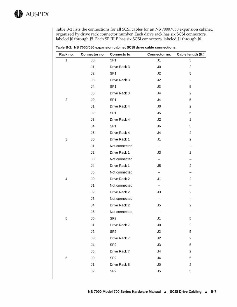
NS 7000 Model 700 Series Hardware Manual ▲ SCSI Drive Cabling ▲ B-7
USPEXA
Table B-2 lists the connections for all SCSI cables for an NS 7000/050 expansion cabinet, organized by drive rack connector number. Each drive rack has six SCSI connectors, labeled J0 through J5. Each SP III-E has six SCSI connectors, labeled J1 through J6.
Table B-2. NS 7000/050 expansion cabinet SCSI drive cable connections
Rack no. Connector no. Connects to Connector no. Cable length (ft.)
1 J0 SP1 J1 5
J1 Drive Rack 3 J0 2
J2 SP1 J2 5
J3 Drive Rack 3 J2 2
J4 SP1 J3 5
J5 Drive Rack 3 J4 2
2 J0 SP1 J4 5
J1 Drive Rack 4 J0 2
J2 SP1 J5 5
J3 Drive Rack 4 J2 2
J4 SP1 J6 5
J5 Drive Rack 4 J4 2
3 J0 Drive Rack 1 J1 2
J1 Not connected – –
J2 Drive Rack 1 J3 2
J3 Not connected – –
J4 Drive Rack 1 J5 2
J5 Not connected – –
4 J0 Drive Rack 2 J1 2
J1 Not connected – –
J2 Drive Rack 2 J3 2
J3 Not connected – –
J4 Drive Rack 2 J5 2
J5 Not connected – –
5 J0 SP2 J1 5
J1 Drive Rack 7 J0 2
J2 SP2 J2 5
J3 Drive Rack 7 J2 2
J4 SP2 J3 5
J5 Drive Rack 7 J4 2
6 J0 SP2 J4 5
J1 Drive Rack 8 J0 2
J2 SP2 J5 5

B-8 ▲ SCSI Drive Cabling ▲ NS 7000 Model 700 Series Hardware Manual
USPEXA
J3 Drive Rack 8 J2 2
J4 SP2 J6 5
J5 Drive Rack 8 J4 2
7 J0 Drive Rack 5 J1 2
J1 Not connected – –
J2 Drive Rack 5 J3 2
J3 Not connected – –
J4 Drive Rack5 J5 2
J5 Not connected – –
8 J0 Drive Rack 6 J1 2
J1 Not connected – –
J2 Drive Rack 6 J3 2
J3 Not connected – –
J4 Drive Rack 6 J5 2
J5 Not connected – –
Table B-2. NS 7000/050 expansion cabinet SCSI drive cable connections (Continued)
Rack no. Connector no. Connects to Connector no. Cable length (ft.)

NS 7000 Model 700 Series Hardware Manual ▲ Network Cables ▲ B-9
USPEXA
Network CablesNetwork cabling specifications for Ethernet, FDDI, MLT-3, and ATM are provided for information only. Auspex does not supply cables to connect the NetServer to the network.
10Base-T EthernetThe 10Base-T connectors use either 100-ohm, category 5, shielded twisted pair (STP) or unshielded twisted pair (UTP) cables, and attach to a network concentrator using standard RJ45 connectors.
If your 10Base-T cable uses an AUI connector, contact your authorized Auspex service representative for information on recommended AUI-to-RJ45 converters.
100Base-T Ethernet (half or full duplex)The 100Base-T Ethernet full-duplex connectors use category 5, data grade, UTP cable or fiber cable over the Media Independent Interface (MII) and attach to a network concentrator using standard RJ45 or MII connectors.
FDDIThe FDDI connectors use 62.5/125-micron or 50/125-micron multimode cables with standard FDDI MIC connectors.
MLT-3The MLT-3 connectors use either 100-ohm, category 5, STP or UTP cables and attach to a network concentrator using standard RJ45 connectors.
Auspex recommends using cables with the EIA/TIA 568B wiring scheme. Table B-3 lists the pin assignments for both connectors on the EIA/TIA 568B cable.
Table B-3. EIA/TIA 568B cable pin and pair assignments
Cable connectors
Pin Pin Pair Color
1 8 2 White/orange
2 7 2 Orange
3 6 3 White/green
4 5 1 Blue
5 4 1 White/blue
6 3 3 Green
7 2 4 White/brown
8 1 4 Brown

ATMThe ATM connector uses a 155 MB-per-second multimode fiber cable with an SC-type connector and attaches to a network concentrator using standard RJ45 connectors. If your site uses ST-type ATM cabling, you need an ST-to-SC converter.

NS 7000 Model 700 Series Hardware Manual ▲ About This Appendix ▲ C-1
USPEXA
C System Console Configurations
About This AppendixThis appendix describes the configuration options for the DEC VT510 system console.
This appendix covers the following sections:
▲ System Console Parameters
▲ System Console Break Function
▲ System Console Delete Key
▲ System Console PgUp and PgDn Keys
▲ Using Diacritics for Key Functions
Refer to the DEC VT510 console user’s manual for additional information.
Note: The following procedures require you to access the Terminal Setup menu by pressing the Caps Lock and Print Screen/Sys Rq keys simultaneously. If this does not work, you can access the Terminal Setup menu by powering off the terminal, powering it on again, and pressing the F3 key.

C-2 ▲ System Console Parameters ▲ NS 7000 Model 700 Series Hardware Manual
USPEXA
System Console ParametersSystem consoles shipped from Auspex are preconfigured and do not require additional steps. However, if you need to reset the parameters for the DEC VT510, follow this procedure.
To reset the parameters for the DEC VT510
1. Press the Caps Lock and the Print Screen/Sys Rq keys simultaneously to display the Terminal Setup menu. The currently selected field, Actions, is highlighted.
Note: Use the Up and Down Arrow keys to select another line on the screen. Use the Right Arrow key to select a submenu. Use the Left Arrow key to return to the previous menu.
2. Use the Right and Down Arrow keys to select Restore factory defaults, and press the Enter key.
3. Use the Left Arrow key to return to the main menu. Select Save settings, and press the Enter key.
4. Select Exit Setup, and press the Enter key.
This concludes the reset procedure for the DEC VT510 terminal.
System Console Break FunctionTo enter a break on the DEC VT510 system console, press the Caps Lock and Pause/Break keys simultaneously. This factory default setting cannot be disabled. However, you can add a different keystroke for the break function by following this procedure.
To enable the Break key on the DEC VT510 console
1. Press the Caps Lock and Print Screen/Sys Rq keys simultaneously to display the Terminal Setup menu.
Note: Use the Up and Down Arrow keys to select another line on the screen. Use the Right Arrow key to select a submenu. Use the Left Arrow key to return to the previous menu.
2. Select Keyboard, and press the Right Arrow key.
3. Select Define key, and press the Enter key.
4. At Press key to be defined, press the Pause/Break key.
5. Use the Down Arrow key to select Unshifted under the Modifiers field, and then press the Right Arrow key to enter the Select function menu.
Note: You may choose another key combination, such as Shifted, to represent the Break function. Unshifted is used as an example.
6. Use the Up Arrow key, and select Break.
7. Press the Enter key.
8. Use the Left Arrow key to return to the Modifiers field.
NS 7000 Model 700 Series Hardware Manual ▲ System Console Delete Key ▲ C-3
USPEXA
9. Use the Down Arrow key to select OK, and press the Enter key.
10. Select Save settings, and press the Enter key.
11. Select Exit Setup, and press the Enter key.
This concludes the procedure for enabling the Break key on the DEC VT510 console.
To disable the Break key on the DEC VT510 console
1. Press the Caps Lock and Print Screen/Sys Rq keys simultaneously to display the Terminal Setup menu.
Note: Use the Up and Down Arrow keys to select another line on the screen. Use the Right Arrow key to select a submenu. Use the Left Arrow key to return to the previous menu.
2. Select Keyboard, and press the Right Arrow key.
3. Select Define key, and press the Enter key.
4. At Press key to be defined, press the Pause/Break key.
5. Use the Down Arrow key to select Unshifted under the Modifiers field, and then press the Right Arrow key to enter the Select function menu.
Note: You may choose another key combination, such as Shifted, to represent the Break function. Unshifted is used as an example.
6. Use the Up Arrow key, and select No function.
7. Press the Enter key.
8. Use the Left Arrow key to return to the Modifiers field.
9. Use the Down Arrow key to select OK, and press the Enter key.
10. Select Save settings, and press the Enter key.
11. Select Exit Setup, and press the Enter key.
This concludes the procedure for disabling the Break key on the DEC VT510 console.
System Console Delete KeyThe Delete key on the DEC VT510 system console does not work properly if you use a different .login file other than the standard one that is shipped with your system for root. For the Delete key to work properly, you must include one of the following commands in your nonstandard .login file:
stty dec
or
stty erase ^?

C-4 ▲ System Console PgUp and PgDn Keys ▲ NS 7000 Model 700 Series Hardware Manual
USPEXA
System Console PgUp and PgDn KeysThe PgUp and PgDn keys on the DEC VT510 system console are not configured to work with the vi editor.
To configure the PgUp and PgDn keys to work with the vi editor
1. Press the Caps Lock and Print Screen/Sys Rq keys simultaneously to display the Terminal Setup menu.
Note: Use the Up and Down Arrow keys to select another line on the screen. Use the Right Arrow key to select a submenu. Use the Left Arrow key to return to the previous menu.
2. Select Keyboard, and press the Right Arrow key.
3. Select Define key, and press the Enter key.
4. When asked Press key to be defined, press the PgUp or PgDn key.
5. Use the Down Arrow key to select Unshifted under the Modifiers field, and then press the Right Arrow key to enter the Select function menu.
6. Select UDK sequence, and press the Enter key. The UDK: field appears.
7. Press Ctrl-B for the PgUp function or Ctrl-F for the page down function according to your selection in step 4.
8. Use the Down Arrow key to select the Apply field.
9. Use the Left Arrow key to select OK, and press the Enter key.
10. At this point, you have configured one of the PgUp and PgDn keys. Repeat steps 2 through 9 to configure the second key.
11. Select Save settings, and press the Enter key.
12. Select Exit Setup, and press the Enter key.
This concludes the procedure for configuring the PgUp and PgDn keys for the DEC VT510 console. You can test the PgUp and PgDn keys using the vi editor.
Using Diacritics for Key FunctionsAuspex recommends that you do not assign diacritics as key functions because they may not function correctly in UNIX. Diacritics are described in the console setup menu under the Define Key Editor as nonspacing accents. Some diacritics include “~” (tilde), “¨” (dieresis), “˘” (breve), and “¸” (cedilla).

Noble:All Files - aedwards:1.9_7000_700_HW���M:HWIGIX;Febru-ary 11, 1997 3:41 pm
NS 7000 Model 700 Series Hardware Manual ▲ Index ▲ i
USPEXA
Index
Numerics100Base-T
cables B-9connecting to a network 3-12interface numbering 3-18network address 3-20
10Base-Tcables B-9connecting to a network 3-12interface numbering 3-18LED display 4-11network address 3-20
AAccess clearance 1-8Air circulation 1-8Air filter maintenance 5-5Altitude
operating 1-8storage 1-8
Antistatic wrist strap 3-4Architecture, FMP 1-1, 1-4ATM
connecting to a network 3-12LED display 4-10
Attaching SCSI devices to the Host Processor 3-27
BBase cabinet
CD-ROM naming A-3dimensions 1-8disk naming A-3 to A-4electrical requirements 1-9opening 2-5power off 4-15power on 4-2space requirements 1-8
subassemblies 2-8tape naming A-3unpacking 2-2
Boot sequence 4-4
CCabinet
components 2-8expansion
components 2-11stabilizing 2-5
Cable100Base-T B-910Base-T B-9console 2-6, B-2Ethernet B-9FDDI B-9identifying (figure) 2-7MLT-3 B-9power 1-11, 2-6, 3-3SCSI 2-7, 3-5, 3-8, B-4
Card cagecomponents 2-18
CD-ROMbooting the server from A-2installing drives A-16naming A-3removing drives A-16
Changing jumper settings A-11Cleaning the NetServer 2-3Cleaning the NetServer air filter 5-5Clearance for NetServer access 1-8Configuration
drive minimum/maximum A-2drive options A-4processor board 1-5, 2-18
Connectingconsole 3-10network cables 3-12

Noble:All Files - aedwards:1.9_7000_700_HW���M:HWIGIX;Febru-ary 11, 1997 3:41 pm
ii ▲ Index ▲ NS 7000 Model 700 Series Hardware Manual
USPEXA
SCSI cables 3-5Console
break function C-2cable 2-6cable specification B-2connecting 3-10installing 3-10page up and page down keys C-4setup parameters 3-10using diacritics C-4
Conventions, numbering 1-7Cutting tie-wraps 3-1
DData integrity 5-9Diagnostic switch on the Host Processor
2-19, 4-2Dimensions
base cabinet 1-8expansion cabinet 1-8
Diskinstallation order A-2installing drives A-16naming A-3naming SCSI devices 3-27removing drives A-16SCSI ID A-12 to A-13slot assignment A-2supported capacities 1-6
DriveCD-ROM drive naming A-3changing SCSI IDs A-11disk naming A-3installation order A-2installing 3-21, 3-25labeling 3-21minimum/maximum A-2rack 3-25relocating A-11removing drives A-16sample configurations A-4SCSI cabling B-4SCSI ID A-12 to A-13SCSI ID label A-11SCSI ID mapping A-19slot assignment A-2slot numbering 3-21 to 3-25tape drive maintenance 5-8types 3-21
Drive racknumbering 3-22 to 3-25
SCSI cabling 3-9
EElectrical requirements
input specifications 1-9power requirements 1-9
Electrostaticdamage 1-9discharge 3-2interference 1-9
EMI screenremoving 5-5
Environmental requirementsoperating altitude 1-8operating temperature 1-8storage altitude 1-8storage temperature 1-8
Ethernetcables B-9connecting to a network 3-12interface numbering 3-18LED display 4-11network address 3-20
Expansion cabinetCD-ROM naming A-3components 2-6dimensions 1-8disk naming A-3 to A-4electrical requirements 1-9opening 2-5power off 4-15power on 4-2power requirements 1-9redundant power supply 5-2SCSI cabling 3-5, 3-8space requirements 1-8subassemblies 2-11supported configurations 1-6tape naming A-3unpacking 2-2
Extended backplane 1-3
FFan trays and LEDs 5-7FDDI
cables B-9connecting to a network 3-12interface numbering 3-18LED display 4-13
FMP (Functional Multiprocessing) 1-1,

NS 7000 Model 700 Series Hardware Manual ▲ Index ▲ iii
Noble:All Files - aedwards:1.9_7000_700_HW���M:HWIGIX;Febru-ary 11, 1997 3:41 pmUSPEXA
1-4Fuse, on the Host Processor 5-11
GGrounding the NetServer 3-2
HHardware features 1-3Host Processor
card cage configuration 1-5, 2-18connectors 2-19Diagnostic switch 2-19fuse 2-19, 5-11LED display 4-10Mbus support 2-18memory 2-18SBus support 2-18SCSI port connections 3-27serial port ttya 2-18serial port ttyb 2-18WarmStart 4-3
Humidity, operating requirements 1-8
IInstalling
antistatic wrist strap 3-4drives 3-21in raised floor environments 3-1
KKeys 2-5
LLED display
10Base-T 4-11ATM 4-10Ethernet 4-11Exabyte 8505 tape drive 5-10fan trays 5-7FDDI 4-13Host Processor 4-10Network Processor 4-10redundant power supplies 5-2 to 5-3
Login prompt 4-9
MMaintenance
air filter 5-5
Exabyte 8505 LEDs 5-10fan trays 5-7power supply LEDs 5-2 to 5-3redundant power supplies 5-2tape drive 5-8tape media 5-8
Mapping SCSI cables to drives A-19Mbus 2-18Memory
Host Processor 2-18Network Processor 2-20
MLT-3cables B-9connecting to a network 3-12interface numbering 3-18
Multiprocessor architecture 1-4
NNetServer
base cabinet 2-8board configuration 1-5card cage 2-18connecting to a network 3-12electrical requirements 1-9environmental requirements 1-8expansion cabinet 1-6, 2-11grounding 3-2hardware features 1-3numbering conventions 1-7opening 2-5space requirements 1-8stabilizing 2-5tools for unpacking 2-2, 3-2unpacking 2-2
Networkconnecting to the 3-12
Network address, Ethernet 3-20Network Processor
100Base-T 3-1210Base-T 3-12ATM 3-12card cage configuration 1-5, 2-20connecting to a network 3-12Ethernet 3-12Ethernet network address 3-20FDDI 3-12interface numbering 3-18LED display 4-10memory 2-20MLT-3 3-12supported configurations 2-20

Noble:All Files - aedwards:1.9_7000_700_HW���M:HWIGIX;Febru-ary 11, 1997 3:41 pm
iv ▲ Index ▲ NS 7000 Model 700 Series Hardware Manual
USPEXA
Numbering conventions 1-7
OOpening the NetServer 2-5Operating altitude 1-8Operating humidity 1-8Operating temperature 1-8
PPower
boot sequence 4-4cable 1-11, 2-6, 3-3main power switch 4-2maintaining redundant power
supplies 5-2power-on self test 4-3shut down procedure 4-15status indicator LEDs 5-2 to 5-3switch 4-2
Power cable configurationsInternational 1-11North America 1-11
Power Distribution Unit (PDU) 2-8Power-on self test 4-3Powering on the NetServer 4-2Procedures
shutting down the NetServer 4-15Processor board
configuration 1-5Host Processor 1-5, 2-18maximum/minimum configuration
2-18Network Processor 1-5, 2-20Storage Processor 1-5, 2-21, 3-8
Prompt, login 4-9
RRedundant power supply
configurations 2-23maintenance 5-2operation 2-23
Removing drives A-16Requirements
access clearance 1-8air circulation 1-8electrical 1-9environmental 1-8power 1-9space 1-8unpacking tools 2-2, 3-2
SSBus 2-18SCSI
attaching devices to the Host Processor 3-27
cabling 2-7, 3-5, 3-9, B-4device names 3-27mapping cables to drives A-19port 3-27
SCSI ID1-GB disk drive A-121.35-GB disk drive A-131/4-inch tape drive A-142.0-GB disk drive A-133.0-GB disk drive A-134-mm tape drive A-144.0-GB disk drive A-13633-MB disk drive A-128-mm (8505) tape drive A-159.0-GB disk drive A-14CD-ROM drive A-15drive slot 3-21Host Processor 3-27jumpers A-11label A-11slot numbering A-2switches A-11
Shutting down the NetServer 4-15Slot assignments 2-22Slot numbering 3-21 to 3-24
drives 3-25, A-2Space requirements 1-8
base cabinet 1-8expansion cabinet 1-8
Stabilizing a cabinet 2-5Storage altitude 1-8Storage Processor
and expansion cabinet 3-8card cage configuration 1-5, 2-21SCSI cabling 3-8
Storage temperature 1-8Switch
diagnostic 2-19, 4-2Host Processor 2-19, 4-2power 4-2reset 2-19
TTape
drive maintenance 5-8

NS 7000 Model 700 Series Hardware Manual ▲ Index ▲ v
Noble:All Files - aedwards:1.9_7000_700_HW���M:HWIGIX;Febru-ary 11, 1997 3:41 pmUSPEXA
installation order A-2installing drives A-16media maintenance 5-8removing drives A-16slot assignment A-2
Temperatureoperating 1-8storage 1-8
Tie-wraps 3-1Tools required for installing components
3-2Tools required for unpacking the
NetServer 2-2, 3-2ttya 2-18ttyb 2-18
UUnlocking the NetServer 2-5Unpacking
base cabinet 2-2expansion cabinet 2-2
WWarmStart 4-3Wrist strap, antistatic 3-4
