nrc nureg on technical considerations for seismic...
TRANSCRIPT

IAEA-ISSC Special Working Group on Seismic Isolation Dr. Annie Kammerer US Nuclear Regulatory Commission Office of Nuclear Regulatory Research
May 2013
NRC NUREG on Technical Considerations for Seismic Isolation of Nuclear Facilities

NRC NUREG
Kammerer1, Whittaker2, and Constantinou2
1US NRC 2University of Buffalo

Research Team • Andrew Whittaker, Michael Constantinou & Yin-Nan
Huang (U of Buffalo) • Annie Kammerer & Richard Rivera-Lugo (NRC) • Robert Budnitz (LBNL) • Boris Jeremic (UC Davis)
External Research Review Group • Robert Kennedy, Chair • Nilesh Chokshi (NRC) • Antonio Godoy (IAEA, retired) • Jim Johnson (James J. Johnson and Associates) • Don Moore (Southern Nuclear) • Jon Stewart (UCLA)
Acknowledgements

• Section on steps to bring new SI components to NRC (same language in ASCE 4)
• NUREG and ASCE 4 edits due to ASCE 4 balloting process • SI chapter and non-mandatory appendix on non-
linear SSI passed and are in final stages of publication
• Edits due to many comment sets received • In final publication
• Second round of internal reviews due to changes from comment sets, ASCE 4 changes, and being a “new technology”
• “sequestration” resource challenges
Changes since 2012

• NRC Earthquake Soil-Structure-Interaction (ESSI) Simulator moving to next phases • Publically available (documentation in final stages
of development) • SI unit implemented and being updated based on
NRC research • NRC staff being trained on system this week to
prepare for SI applications • Areva Germany is running system as part of multi-
tool comparison/assessment project
Changes since 2012

• In 2008 NRC began new research in SI • NRC research addressed key items
• Vertical and beyond-design-basis loading • Development of isolator component for NRC’s ESSI
Simulator. • Testing of full size isolator systems at large loads on
eDefence to confirm analysis tools and models • Development of deterministic “rules of thumb” to provide
conservative factors for performance criteria • Performance-based criteria for regulation of NPPs using
seismic isolation systems (NUREG chapters 8 &9) • Research program refunded May 2012
Regulatory Activities

• Final Draft NUREG sent into final review June 2012 • 2 month final internal review • 1-2 month technical editing review • 1-2 month publications review • Publication expected mid-2013
• Additional research published as NUREG/CR reports on each of the technical topics
• Regulatory Guide on Seismic Isolation will be developed
Regulatory Activities

NUREG Table of Contents
1. Introduction 2. Brief History Of Seismic Isolation 3. Basics Of Seismic Isolation 4. Mechanics Of Seismic Isolators 5. Guidance In US Codes And Standards 6. Regulatory Guidance in Japan 7. Modeling Techniques For Seismically Isolated Structures 8. Performance Objectives and Acceptance Criteria for
Seismic Isolation for US Nuclear Facility Structures 9. Additional Recommendations 10. References

NUREG Philosophy in Defining Risk and Performance Criteria
The element used in creating the performance criteria include the following:
• The isolators cannot be allowed to fail and should be removed from any realistic sequence. • Singletons that are safety related must have more stringent design criteria than more conventional construction. • The concepts of FOSID and HCLPF should be incorporated to the extent possible, recognizing that seismic isolators are inherently non-linear. • The extended DBE concept discussed in the Near Term Task Force Report should be incorporated. • The potential for cliff edge effects must be removed through use of a hard stop.

NUREG Philosophy in Defining Risk and Performance Criteria
• Assurance of performance must incorporate a combination of prototype and production testing to physically demonstrate quantifiable confidence levels and performance reliability in both the isolators and the umbilicals. • Guidance must consider how seismic isolation systems could fit within a certified design framework. (Design of the Basemat up is certified and isolators tuned to the site) • Although the guidance focuses on isolated light water reactor superstructures, the approach should be technology neutral enough to be extended to other designs, such as for small modular reactors. • Realistic approaches for achieving clear and technically based performance targets should be described.
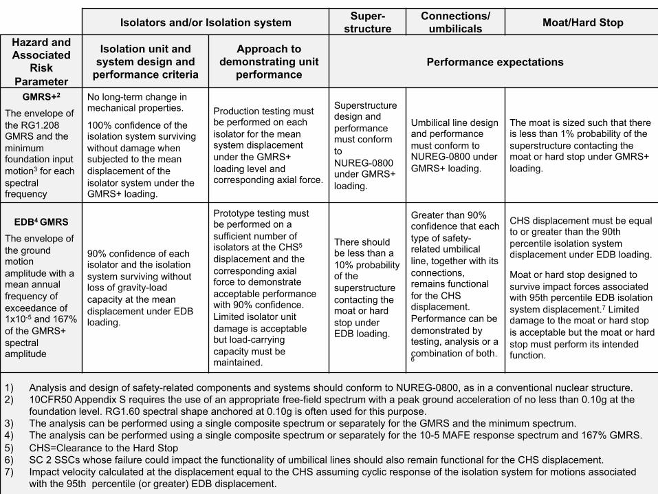
Isolators and/or Isolation system Super-structure
Connections/ umbilicals Moat/Hard Stop
Hazard and Associated
Risk Parameter
Isolation unit and system design and
performance criteria
Approach to demonstrating unit
performance Performance expectations
GMRS+2 The envelope of the RG1.208 GMRS and the minimum foundation input motion3 for each spectral frequency
No long-term change in mechanical properties. 100% confidence of the isolation system surviving without damage when subjected to the mean displacement of the isolator system under the GMRS+ loading.
Production testing must be performed on each isolator for the mean system displacement under the GMRS+ loading level and corresponding axial force.
Superstructure design and performance must conform to NUREG-0800 under GMRS+ loading.
Umbilical line design and performance must conform to NUREG-0800 under GMRS+ loading.
The moat is sized such that there is less than 1% probability of the superstructure contacting the moat or hard stop under GMRS+ loading.
EDB4 GMRS The envelope of the ground motion amplitude with a mean annual frequency of exceedance of 1x10⁻⁵ and 167% of the GMRS+ spectral amplitude
90% confidence of each isolator and the isolation system surviving without loss of gravity-load capacity at the mean displacement under EDB loading.
Prototype testing must be performed on a sufficient number of isolators at the CHS5 displacement and the corresponding axial force to demonstrate acceptable performance with 90% confidence. Limited isolator unit damage is acceptable but load-carrying capacity must be maintained.
There should be less than a 10% probability of the superstructure contacting the moat or hard stop under EDB loading.
Greater than 90% confidence that each type of safety-related umbilical line, together with its connections, remains functional for the CHS displacement. Performance can be demonstrated by testing, analysis or a combination of both.6
CHS displacement must be equal to or greater than the 90th percentile isolation system displacement under EDB loading. Moat or hard stop designed to survive impact forces associated with 95th percentile EDB isolation system displacement.7 Limited damage to the moat or hard stop is acceptable but the moat or hard stop must perform its intended function.
1) Analysis and design of safety-related components and systems should conform to NUREG-0800, as in a conventional nuclear structure. 2) 10CFR50 Appendix S requires the use of an appropriate free-field spectrum with a peak ground acceleration of no less than 0.10g at the
foundation level. RG1.60 spectral shape anchored at 0.10g is often used for this purpose. 3) The analysis can be performed using a single composite spectrum or separately for the GMRS and the minimum spectrum. 4) The analysis can be performed using a single composite spectrum or separately for the 10-5 MAFE response spectrum and 167% GMRS. 5) CHS=Clearance to the Hard Stop 6) SC 2 SSCs whose failure could impact the functionality of umbilical lines should also remain functional for the CHS displacement. 7) Impact velocity calculated at the displacement equal to the CHS assuming cyclic response of the isolation system for motions associated
with the 95th percentile (or greater) EDB displacement.

Isolators and/or Isolation system Super-structure
Connections/ umbilicals Moat/Hard Stop
Hazard and Associated
Risk Parameter
Isolation unit and system design and performance
criteria
Approach to demonstrating unit
performance Performance expectations
GMRS+2 Envelope of the RG1.208 GMRS and the minimum foundation input motion3 for each spectral frequency
No long-term change in mechanical properties. 100% confidence of the isolation system surviving without damage when subjected to the mean displacement of the isolator system under the GMRS+ loading.
Production testing must be performed on each isolator for the mean system displacement under the GMRS+ loading level and corresponding axial force.
Super-structure design and performance must conform to NUREG-0800 under GMRS+ loading.
Umbilical line design and performance must conform to NUREG-0800 under GMRS+ loading.
The moat is sized such that there is less than 1% probability of the superstructure contacting the moat or hard stop under GMRS+ loading.
2) 10CFR50 Appendix S requires the use of an appropriate free-field spectrum with a peak ground acceleration of no less than 0.10g at the foundation level. RG1.60 spectral shape anchored at 0.10g is often used for this purpose.
3) The analysis can be performed using a single composite spectrum or separately for the GMRS and the minimum spectrum.

Isolators and/or Isolation system Super-structure
Connections/ umbilicals Moat/Hard Stop
Hazard and Associated
Risk Parameter
Isolation unit and system design
and performance criteria
Approach to demonstrating unit
performance Performance expectations
EDB4 GMRS The envelope of the ground motion amplitude with a mean annual frequency of exceedance of 1x10⁻⁵ and 167% of the GMRS+ spectral amplitude
90% confidence of each isolator and the isolation system surviving without loss of gravity-load capacity at the mean displacement under EDB loading.
Prototype testing must be performed on a sufficient number of isolators at the CHS5 displacement and the corresponding axial force to demonstrate acceptable performance with 90% confidence. Limited isolator unit damage is acceptable but load-carrying capacity must be maintained.
There should be less than a 10% probability of the super-structure contacting the moat or hard stop under EDB loading.
Greater than 90% confidence that each type of safety-related umbilical line, together with its connections, remains functional for the CHS displacement. Performance can be demonstrated by testing, analysis or a combination of both.6
CHS displacement must be equal to or greater than the 90th percentile isolation system displacement under EDB loading. Moat or hard stop designed to survive impact forces associated with 95th percentile EDB isolation system displacement.7 Limited damage to the moat or hard stop is acceptable but the moat or hard stop must perform its intended function.
4) The analysis can be performed using a single composite spectrum or separately for the 10-5 MAFE response spectrum and 167% GMRS.
6) SC 2 SSCs whose failure could impact the functionality of umbilical lines should also remain functional for the CHS displacement.
7) Impact velocity calculated at the displacement equal to the CHS assuming cyclic response of the isolation system for motions associated with the 95th percentile (or greater) EDB displacement.

Additional Requirements
• Guidance will focus on technologies with track record in US and with stable properties over time. Only natural rubber bearings, lead rubber bearings, and friction pendulum bearings that have a natural restoring force are appropriate. Neoprene, high damping bearings, springs, etc. are not allowable.
• Vertical isolation systems could be allowable. • Isolation of individual pieces of equipment or floor
isolation is possible, but is not addressed in the NUREG. The concepts can be extended to other uses.

Analysis Requirements
• Three options: 1) coupled time domain, 2) coupled frequency domain, and 3) multi-step
• Coupled 3D time domain modeling has no usage restrictions
• Coupled frequency domain can only be used with low damping rubber bearings (essentially linear) without damping and in certain limited circumstances. The following preclude use:
• The shear strain expected for the chosen intensity of shaking (CHS) exceeds the shear strain at the onset of stiffening
• Coupling of the vertical and horizontal responses is likely at the shear strain expected for the chosen intensity of shaking (CHS)
• Cavitation is expected in the LDR bearings for the chosen intensity of shaking

Analysis Requirements
• Multi-step includes the following: • Step 1: Development of seismic input design
response spectrum (SIDRS) through SSI analyses using a simple structural model. Either time or frequency domain approaches can be used, but in the later approach the equivalent isolator must be developed.
• Step 2: Nonlinear response-history analysis of the isolated superstructure using coupled 3D time domain modeling. The SIDRS is used as input below the isolation system.

Design and Analysis Requirements
• The analysis and design must account for aging, creep, operating temperature, exposure to moisture or damaging substances, and any other deleterious substances present in the immediate vicinity of the isolators.
• The mechanical properties of the isolation system (i.e., the force-displacement relationship) should not vary over the lifespan of the structure by more than ±20% from the best-estimate values (with 95% probability) from those assumed for analysis and design.

Design and Analysis Requirements
• The superstructure basemat must be able to span a lost isolator unit, even one on the perimeter.
• The superstructure basemat and foundation raft must be sufficiently rigid to assure that the vertical loads on the isolators are relatively uniform.
• The potential for long-term settlement must be accounted for.

Design and Analysis Requirements
• Soil-structure-isolator-systems must generally be analyzed using three-dimensional time-domain fully non-linear analysis of the complete system.
• Appropriate long-period content and duration of input earthquake records must be demonstrated.
• The isolator unit numerical model must be validated against actual data. (NRC has performed testing on eDefense)

Design and Analysis Requirements
• Additional seismic monitoring equipment must be incorporated along the edge of the basemat to capture rotation and rocking motions in the event of an earthquake.
• The SI system must be protected against, or designed for fire, high winds, flood, and other natural hazards.
• Consideration should also be given to extreme loadings such as aircraft impact and air-blast and ground shock loadings due to accidental and malevolent explosions.
Design and Analysis Requirements
• Umbilicals and other connections are critical. Safety related umbilical must be analyzed for beyond-design-basis events.
• Vertical load affects isolator properties; slabs below and above the individual isolators are not perfectly rigid elements, and rocking motions can occur. All appropriate elements related to vertical loading and vertical response must be incorporated into design and analysis.

Design and Analysis Requirements
• Isolators and their fire protection systems are safety related equipment
• In order to assure survivability of the SI system, a hard stop is required.
• Passive systems should be used. • Design should address LOSP and other emergency
conditions.

QA/QC & Construction Requirements
• QA/QC procedures should be developed based on ANSI/ASME NQA-1-2008, “Quality Assurance Requirements for Nuclear Facility applications”. While the isolation system as a whole acts as a structural element, individual isolators are mechanical components subject to the requirements of 10 CFR 50, Appendix B.
• QA/QC approach for testing in ASCE 7-10 can be used as a base, but must meet the criteria in Chapter 8 for prototype and production testing.

Operational Requirements
• An in-unit inspection program is required and the design must allow for replacements
• Aging and radiological degradation must be accounted for in the inspection plan of NPPs.
• The isolators must recover quickly enough to withstand large aftershocks within tens of minutes.
• Isolators should have an inherent property that passively re-centers the system.
• The protection of the seismic isolation system should be included in emergency and severe accident mitigation planning where appropriate

Peer Review Requirements
• Professional peer review must be incorporated into the design and development process.
• Review of numerical models of isolators • Review of the SSI analysis and the in-structure response spectra • Review of displacement and force calculations for the isolator units and all associated structures, systems, and components • Review of the analysis and design of the umbilicals • Review of the analysis and design of the hard stop • Review of the seismic monitoring program • Review of the prototype test program • Review of the production (quality control) test program • Review of the isolator inspection and post-installation testing program • Review of post-earthquake inspection protocols • Review of design or protection measures against other external events.

SI Working Group Goals
From IAEA Working Group 2.1 Meeting April 2011 This subtask is aimed to develop technical basis for deriving requirements and/or restrictions related to use of seismic base isolation solutions in nuclear installations. The outcome of this sub-task will be a technical report summarizing the technical issues related to base isolation solutions in nuclear installations. NUREG and JNES SS both have lots of useful (and generally compatible) information to provide. Both are written for the experienced designer; neither provides basic discussions called for in the earlier discussion.

SI Working Group Goals
From IAEA Working Group 2.1 Meeting April 2011 The technical report should address the following: • Seismic Isolation Concept (Chapter) • Dynamics of a seismically isolated system (Section 3.1 and Chapter 4) • Benefits of SI (Section 1.1) • Available SI technologies (Section 3.3 and Chapter 4) • Industry experience: Design Basis and Beyond Design Basis (Chapter 2)

SI Working Group Goals
From IAEA Working Group 2.1 Meeting April 2011 The technical report should address the following: (Chapter 8 provides criteria to avoid) • Un-acceptable performance of SI Systems:
• Exceeding deformation capacity • Exceeding vertical deformation capacity • Loss of Stability in compression • Failure of isolator attachments • Impact of the isolated structure resulting in high-frequency excitation of the isolated super-structure • Local failure of the foundation or isolation diaphragms • Inability to redistribute loads in case of one isolator failure

SI Working Group Goals
From IAEA Working Group 2.1 Meeting April 2011 The technical report should address the following: • Interaction between the soil, foundation, seismic isolation, and the isolated structure (Chapter 7 doesn’t explain, but addresses modeling) • SSI + Seismic Isolation Analysis Challenges (Chapter 7 doesn’t explain, but addresses modeling) • Response to other dynamic loads of a SI system (Not included, references could be added) • Acceptance Criteria (Chapters 8 and 9) • Validation requirements of the SI system (Chapter 8)

SI Working Group Goals
From IAEA Working Group 2.1 Meeting April 2011 Lessons to be learned after Fukushima event (accident): • Combination of hazards (seismic, flood, fire, explosions) • Exceedance of (design basis) estimated level of protection for tsunami • Vulnerability of critical safety functions in respect to (combination of) External Events

31
THANK YOU