nr physical layer design: physical layer structure, numerology … · 2019-07-30 · workshop on...
TRANSCRIPT

Workshop on 3GPP submission towards IMT-2020, Brussels, Oct. 24-25, 2018
© 3GPP 2012
© 3GPP 2018 1
NR Physical Layer Design: Physical layer structure, numerology and frame structure
Havish Koorapaty3GPP TSG RAN WG1 vice-chairman (Ericsson)

Workshop on 3GPP submission towards IMT-2020, Brussels, Oct. 24-25, 2018
© 3GPP 2012
© 3GPP 2018 2
NR – Key benefits
Wide spectrum rangeUltra-lean
Forward compatibility
Low latencyMulti-antenna
New capabilities
New technology components
1 GHz 3 GHz 10 GHz 30 GHz 100 GHz

Workshop on 3GPP submission towards IMT-2020, Brussels, Oct. 24-25, 2018
© 3GPP 2012
© 3GPP 2018 3
Minimize “always-on” transmissions (ultra-lean)
Bad example: Always-on CRS
Keep transmissions together in frequency
Bad example: LTE PDCCH/PCFICH/PHICH
Avoid static/strict timing relations
Bad example: LTE uplink HARQ
Reserved resources
Downlink transmissions rate matched around
Forward compatibility
New capabilities
New technology components

Workshop on 3GPP submission towards IMT-2020, Brussels, Oct. 24-25, 2018
© 3GPP 2012
© 3GPP 2018 4
Frequency bands
1 GHz 3 GHz 10 GHz 30 GHz 100 GHz
Subcarrier spacing 15/30/60 kHz
Max carrier bandwidth 50/100/200 MHz
Spectrum allocations identified or NR
Subcarrier spacing 60/120 kHz
Max carrier bandwidth 200/400 MHz
Frequency Range 1 Frequency Range 2
Mainly paired spectrum
Mainly unpaired spectrum

Workshop on 3GPP submission towards IMT-2020, Brussels, Oct. 24-25, 2018
© 3GPP 2012
© 3GPP 2018 5
Time-frequency structure

Workshop on 3GPP submission towards IMT-2020, Brussels, Oct. 24-25, 2018
© 3GPP 2012
© 3GPP 2018 6
Frame structure
Single frame structure Applicable to FDD and TDD
Dynamic TDD baselinePossible to semi-statically configure UL/DL split
15 kHz slot identical to LTE subframe
Including extra samples in every 7th symbol
One subframe, Tsubframe = 1 ms
#0 #1 #9
One frame, Tframe = 10 ms
#8#2 #3 #4 #5 #6 #7
Δf=15 kHz
Δf=30 kHz
Δf=60 kHz
Δf=120 kHz
Δf=240 kHz
One slot, 0.25 ms
One slot, 1 ms
One slot, 0.5 ms
One slot, 0.125 ms
One slot, 0.0625 ms

Workshop on 3GPP submission towards IMT-2020, Brussels, Oct. 24-25, 2018
© 3GPP 2012
© 3GPP 2018 7
Frame structure
Transmissions not restricted to slot boundaries
Channel available
Data arrival
Channel availableDummy data
Efficiency loss
One slot
Long latency
Data arrival
Short latency
Unused
Transmissions restricted to slot boundaries Transmissions not restricted to slot boundaries
Useful data Useful dataUseful data
Workshop on 3GPP submission towards IMT-2020, Brussels, Oct. 24-25, 2018
© 3GPP 2012
© 3GPP 2018 8
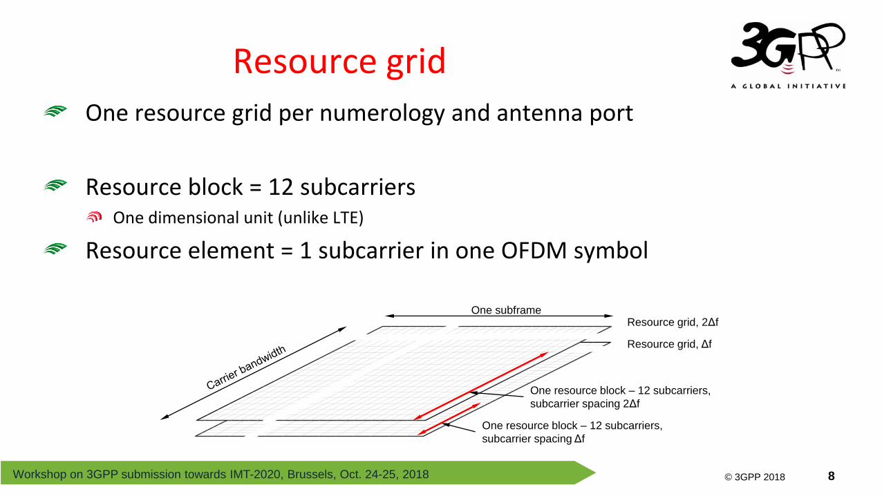
One subframe
One resource block – 12 subcarriers,
subcarrier spacing 2Δf
One resource block – 12 subcarriers,
subcarrier spacing Δf
Resource grid, 2Δf
Resource grid, Δf
Resource gridOne resource grid per numerology and antenna port
Resource block = 12 subcarriersOne dimensional unit (unlike LTE)
Resource element = 1 subcarrier in one OFDM symbol

Workshop on 3GPP submission towards IMT-2020, Brussels, Oct. 24-25, 2018
© 3GPP 2012
© 3GPP 2018 9
Resource-block grid
CRB grid for Δf
PRB grid for Δf
M-10 1 2 3 4 …
0 1 2 3 4 5 m-2 m-1 m m+1m+2 …
0 1 2 3 … n n+1 n+2 …n-2 n-1
CRB grid for 2Δf
Reference point A
Carrier edge
Bandwidth part #1 at Δf starts as CRB m
Bandwidth part #2 at 2Δf starts as CRB n
PRB grid for 2Δf
…
N-10 1 2 …
Spectrum allocation available for the carrier

Workshop on 3GPP submission towards IMT-2020, Brussels, Oct. 24-25, 2018
© 3GPP 2012
© 3GPP 2018 10
Bandwidths
Up to 400 MHz component-carrier bandwidth (20 MHz for LTE)
Up to 16 component carriersOverall bandwidth depends on frequency band
Not all devices must support the full network carrier bandwidth
A UE can support less than the carrier BW
LTE NR
20 MHz
5 (later 32) component carriers
All UEs support full carrier BW
Up to 400 MHz
Up to 16 component carriers

Workshop on 3GPP submission towards IMT-2020, Brussels, Oct. 24-25, 2018
© 3GPP 2012
© 3GPP 2018 11
Bandwidth partsTo support UEs not capable of full carrier bandwidth
To support bandwidth adaptation (reduced UE power consumption)
Up to 4 bandwidth parts per carrier, one of which is active
A UE is not supposed to receive/transmit outside the active bandwidth part
Many parameters are configured per bandwidth part
time
frequency Switch of active bandwidth part
BWP #1 active BWP #2 active BWP #1 active

Workshop on 3GPP submission towards IMT-2020, Brussels, Oct. 24-25, 2018
© 3GPP 2012
© 3GPP 2018 12
Supplementary uplinkMain use case: uplink coverage
Carrier aggregation (up to 16 carriers)
Main use case: bandwidth extension
Carrier aggregation and supplementary uplink
Cell #1 Cell #2 A single cell
Carrier aggregation Supplementary uplink

Workshop on 3GPP submission towards IMT-2020, Brussels, Oct. 24-25, 2018
© 3GPP 2012
© 3GPP 2018 13
Downlink and uplink co-existence Uplink-only co-existence
NR
LTE
NR
LTE
NR-LTE Coexistence
NR can coexist with LTE on the same carrier
Example: NB-IoT or eMTC for MTC on same carrier as NR

Workshop on 3GPP submission towards IMT-2020, Brussels, Oct. 24-25, 2018
© 3GPP 2012
© 3GPP 2018 14
Reserved resourcesTo enable coexistence with LTE/NB-IoT on the downlink
Treat LTE CRS as reserved resources
To facilitate forward compatibility in downlink
Three sets can be configured using a set of bitmaps
Dynamic indication of whether resources are reserved or not
Indicator #1 Indicator #2
Indication in DCI 0,0 0,1 1,0 1,1
Set #1 Set #2 Set #3

Workshop on 3GPP submission towards IMT-2020, Brussels, Oct. 24-25, 2018
© 3GPP 2012
© 3GPP 2018 15
Transport channel processing

Workshop on 3GPP submission towards IMT-2020, Brussels, Oct. 24-25, 2018
© 3GPP 2012
© 3GPP 2018 16
Overall transport-channel processing resembles LTE
Main differences:LDPC coding
Multi-antenna handling
OFDM and DFTS-OFDM in UL
Transport-Channel Processing
CRC
LDPC coding
Rate matching, hybrid-ARQ
Scrambling
Modulation
Layer mapping
Transform precoding
(UL only)
Multi-antenna precoding
Resource mapping
Physical antenna mapping
One (or two) transport block(s) of dynamic
size delivered from the MAC layer

Workshop on 3GPP submission towards IMT-2020, Brussels, Oct. 24-25, 2018
© 3GPP 2012
© 3GPP 2018 17
Code-block segmentationCRC per TB and CB (as in LTE)
LDPC codingTwo base graphs
Coding
To channel coding
Transport block CRC
Code block #1 CRC Code block #2 CRC Code block #3 CRC
TB-CRC
CB-CRC
2/3
1/4
Transport block size
Code rate for
initial transmission
292 bits 3824 bits
BG1
BG2

Workshop on 3GPP submission towards IMT-2020, Brussels, Oct. 24-25, 2018
© 3GPP 2012
© 3GPP 2018 18
Circular buffer rate matchingSome systematic bits removed prior to circular buffer insertion
4 different redundancy versions
Limited-buffer rate matchingTo handle limited UE soft-buffer size
Determines amount of bits put into the circular buffer
Can also be used in UL
Rate MatchingRV0
RV1
RV2
RV3
1st transmission
2nd transmission
3rd transmission
4th transmission
Soft buffer size
Systematic bits Parity bits
Soft buffer size
Systematic bits Parity bits
These 1/3 of bits will
never be transmitted
These 2/3 of bits may be transmitted
Largest transport-
block size
Smaller transport-
block sizes
1/3 2/3
1/3 2/3
1/3 2/3
1/3 2/3

Workshop on 3GPP submission towards IMT-2020, Brussels, Oct. 24-25, 2018
© 3GPP 2012
© 3GPP 2018 19
Hybrid ARQ
Similar to LTE but with some differencesPossibility for per-CBG retransmission
Asynchronous in DL and UL (up to 16 processes)
Transport block
0 1 0 0
CBG
CBGTI
Only this CBG is retransmitted
Flushing of soft buffer controlled by CBGFITo soft combining

Workshop on 3GPP submission towards IMT-2020, Brussels, Oct. 24-25, 2018
© 3GPP 2012
© 3GPP 2018 20
Control channels

Workshop on 3GPP submission towards IMT-2020, Brussels, Oct. 24-25, 2018
© 3GPP 2012
© 3GPP 2018 21
Downlink L1/L2 control signaling
Downlink Control information (DCI), transmitted on PDCCH
Similar usage as in LTE (scheduling, …)
PDCCHThe only type of L1/L2 control channel in NR
No PCFICH or PHICH (not needed in NR)
Main difference compared to LTEPossibility for beamforming
Not necessarily spanning full carrier bandwidth

Workshop on 3GPP submission towards IMT-2020, Brussels, Oct. 24-25, 2018
© 3GPP 2012
© 3GPP 2018 22
PDCCH Processing
Similar processing chain as for LTE
Polar coding
Larger CRC
Each PDCCHIndependently processed
Has its own DM-RS
Downlink Control Information
RNTI
Mapping to resource elements
DM-RS
K bit payload
K bit payload 24-bit CRCNULL
140 bits
RNTI
+
No puncturing Puncturing Shortening Repetition
24-bit CRC
attachment
CRC
interleaver
RNTI
encoding
Polar
coding
Rate
matching
Scrambling
QPSK

Workshop on 3GPP submission towards IMT-2020, Brussels, Oct. 24-25, 2018
© 3GPP 2012
© 3GPP 2018 23
PDCCH Monitoring
CORESET (Control Resource Set)Time-frequency region where the UE monitors for PDCCH transmission
Multiple CORESETs can be configured in a UE using RRC signaling
CORESET0 obtained from MIB
Search spacesSet of CCEs upon which the UE tries to blindly detect PDCCH transmissions
One PDCCH transmitted using aggregation level 1, 2, 4, 8, or 16 CCEs
CCE-to-REG
mapping
Search spaceSearch space
Search space
PDCCH candidatePDCCH candidate
PDCCH candidate
Set of REGs Set of CCEs

Workshop on 3GPP submission towards IMT-2020, Brussels, Oct. 24-25, 2018
© 3GPP 2012
© 3GPP 2018 24
CORESET
Multiple CORESETs can be configured in one UE
Not necessarily located at the beginning of the slot
Frequency span in multiples of 6 RB
Time span of 1, 2, or 3 OFDM symbols
CORESET resources can be reused for data
Use reserved resources mechanism
CORESET #1
CORESET #2
CORESET #3
CORESET #4
one slot
PDCCH in this CORESET
(indicated as reserved)
Data scheduled on unused
CORESET resources
Data can start before
the end of the PDCCH

Workshop on 3GPP submission towards IMT-2020, Brussels, Oct. 24-25, 2018
© 3GPP 2012
© 3GPP 2018 25
CCE-to-REG mappingEach CORESET has an associated CCE-to-REG mapping
Interleaved mapping
Non-interleaved mapping
13
14
15
16
17
8
9
10
11
12
0
1
2
3
4
5
6
7
26
28
30
32
34
0
2
4
6
8
10
12
14
16
18
20
22
24
27
29
31
33
35
1
3
5
7
9
11
13
15
17
19
21
23
25
13
14
15
16
17
8
9
10
11
12
0
1
2
3
4
5
6
7
REG bundle
REG
CCE
PDCCH
1 symbol CORESET 2 symbol CORESET 1 symbol CORESET
bundling size 2
2 symbol CORESET
bundling size 2
26
28
30
32
34
0
2
4
6
8
10
12
14
16
18
20
22
24
27
29
31
33
35
1
3
5
7
9
11
13
15
17
19
21
23
25
REG bundle
2 symbol CORESET
bundling size 6
non-interleaved mapping interleaved mapping
REGs
OFDM symbol
26
28
30
32
34
0
2
4
6
8
10
12
14
16
18
20
22
24
3
27
29
31
33
35
1
5
7
9
11
13
15
17
19
21
23
25
3
CORESET

Workshop on 3GPP submission towards IMT-2020, Brussels, Oct. 24-25, 2018
© 3GPP 2012
© 3GPP 2018 26
DM-RS and QCL
Each PDCCH has its own DM-RS……but possible to configure ‘wideband RS’
DM-RS on every 4th subcarrier
Can configure TCI states (QCL relations) per CORESET
If none configured – assume QCL with SS block
CORESET
REGs for
PDCCH #1
DM-RS for
PDCCH #1
DM-RS for
PDCCH #2REGs for
PDCCH #2
REGs for
PDCCH #1
REGs for
PDCCH #2
DM-RS for all
PDCCHs in the
CORESET
CORESET
Normal case – DM-RS per PDCCH Wideband RS
one slot
CORESET #1: CSI-RS #1 QCL:ed with DM-RS
CORESET #2: CSI-RS #2 QCL:ed with DM-RS

Workshop on 3GPP submission towards IMT-2020, Brussels, Oct. 24-25, 2018
© 3GPP 2012
© 3GPP 2018 27
Blind DecodingBlind decoding of PDCCH using search spaces and DCI formats
Similar concept as in LTE
Aggregation level 1, 2, 4, 8, or 16
Flexible configuration of when, what formats, and what aggregation levels to monitor
CORESETs with search spaces for aggregation level 2 monitored
Aggregation level 4 monitoredNo monitoring in this occasion of the search space No monitoring in this occasion of the search space
one slot

Workshop on 3GPP submission towards IMT-2020, Brussels, Oct. 24-25, 2018
© 3GPP 2012
© 3GPP 2018 28
DCI formatsFormat 0-0 – uplink scheduling (fallback format)
Format 0-1 – uplink scheduling
Format 1-0 – downlink scheduling (fallback format)
Format 1-1 – downlink scheduling
Format 2-0 – slot-format indicator
Format 2-1 – preemption indictor
Format 2-2 – PUSCH/PUCCH power control
Format 2-3 – SRS power control
Field Format 1-0 Format 1-1
Format
identifier
• •
Resource
information
CFI •
BWP indicator •
Frequency domain
allocation • •
Time-domain allocation • •
VRB-to-PRB mapping • •
PRB bundling size
indicator
•
Reserved resources •
Zero-power CSI-RS
trigger
•
Transport-
block related
MCS • •
NDI • •
RV • •
MCS, 2nd TB •
NDI, 2nd TB •
RV, 2nd TB •
Hybrid-ARQ
related
Process number • •
DAI • •
PDSCH-to-HARQ
feedback timing • •
CBGTI •
CBGFI •
Multi-antenna
related
Antenna ports •
TCI •
SRS request •
DM-RS sequence
initialization
•
PUCCH-
related
information
PUCCH power control • •
PUCCH resource indicator •
See 38.212 for an up-to-date detailed list

Workshop on 3GPP submission towards IMT-2020, Brussels, Oct. 24-25, 2018
© 3GPP 2012
© 3GPP 2018 29
Frequency-domain resource allocation
Resource allocation type 0 – bitmap, each bit corresponds to a group of RBs
Resource allocation type 1 – start and length of RB allocation
The type to use is RRC configured (always 0, always 1, dynamic selection of 0/1)Uplink transmissions limited to contiguous allocations in Rel-15
0 1 2 3 4 5 6 7 8 9 10 11 12 13 14 15 16 17 18 19 20 21 22 23 24
0 1 2 3 4 5 6 7 8 9 10 11 12 13 14 15 16 17 18 19 20 21 22 23 24
Bitmap
Type 0
Type 1
1 0 0 1 1 1 0 1 0 0 0 1 0
Start Length

Workshop on 3GPP submission towards IMT-2020, Brussels, Oct. 24-25, 2018
© 3GPP 2012
© 3GPP 2018 30
Time-domain resource allocation
Index into RRC-configured tableDefault values specified (needed before configuration)
Index Slot
offset
Start
symbol
Length PDSCH
mapping type
0 0 2 12 A
1 0 2 10 A
2 1 3 4 B
… … … … …
Jointly encoded
slot
4 OFDM
symbols
RRC configured
Workshop on 3GPP submission towards IMT-2020, Brussels, Oct. 24-25, 2018
© 3GPP 2012
© 3GPP 2018 31
Time-domain allocation
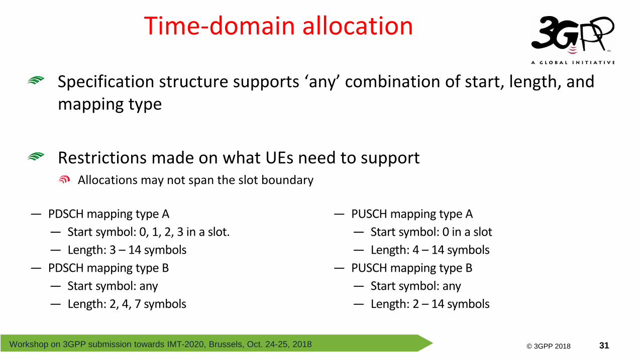
Specification structure supports ‘any’ combination of start, length, and mapping type
Restrictions made on what UEs need to supportAllocations may not span the slot boundary
— PUSCH mapping type A
— Start symbol: 0 in a slot
— Length: 4 – 14 symbols
— PUSCH mapping type B
— Start symbol: any
— Length: 2 – 14 symbols
— PDSCH mapping type A
— Start symbol: 0, 1, 2, 3 in a slot.
— Length: 3 – 14 symbols
— PDSCH mapping type B
— Start symbol: any
— Length: 2, 4, 7 symbols
Workshop on 3GPP submission towards IMT-2020, Brussels, Oct. 24-25, 2018
© 3GPP 2012
© 3GPP 2018 32
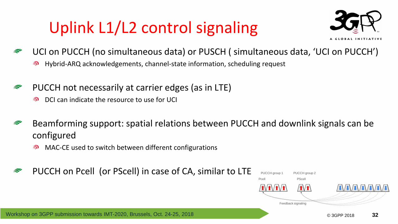
Uplink L1/L2 control signalingUCI on PUCCH (no simultaneous data) or PUSCH ( simultaneous data, ‘UCI on PUCCH’)
Hybrid-ARQ acknowledgements, channel-state information, scheduling request
PUCCH not necessarily at carrier edges (as in LTE)DCI can indicate the resource to use for UCI
Beamforming support: spatial relations between PUCCH and downlink signals can be configured
MAC-CE used to switch between different configurations
PUCCH on Pcell (or PScell) in case of CA, similar to LTE PUCCH group 1 PUCCH group 2
Pcell PScell
Feedback signaling

Workshop on 3GPP submission towards IMT-2020, Brussels, Oct. 24-25, 2018
© 3GPP 2012
© 3GPP 2018 33
PUCCH formats
Five different PUCCH formats
All designed with low PAPR in mind, can be used irrespective of PUSCH waveform
Payload Short (1-2 OFDM symbol) Long (4 – 14 OFDM symbols)
≤2 bits PUCCH format 0 PUCCH format 1
>2 bits PUCCH format 2 PUCCH formats 3 and 4

Workshop on 3GPP submission towards IMT-2020, Brussels, Oct. 24-25, 2018
© 3GPP 2012
© 3GPP 2018 34
PUCCH TimingPUCCH timing and resources indicated in the DCI
In essence ‘scheduling’ of PUCCH
Much faster processing time than in LTE
Downlink
controlDownlink
data
Index Offset
0 ΔT0
1 ΔT1
2 ΔT2
3 ΔT3
… …
Uplink
ACK
ACK timing ΔT3
Ind
ex
3
slot
RRC-configured table
ΔT2
DM-RS
configuration
Device
capability
Subcarrier spacing LTE
rel 8 15 kHz 30 kHz 60 kHz 120 kHz
Front-loaded Baseline 0.57 ms 0.36 ms
0.30 ms 0.18 ms
2.3 ms Aggressive 0.18 – 0.29 ms 0.08 – 0.17 ms
Additional Baseline 0.92 ms 0.46 ms
0.36 ms 0.21 ms Aggressive 0.85 ms 0.4 ms

Workshop on 3GPP submission towards IMT-2020, Brussels, Oct. 24-25, 2018
© 3GPP 2012
© 3GPP 2018 35
Cell search and Random access
Workshop on 3GPP submission towards IMT-2020, Brussels, Oct. 24-25, 2018
© 3GPP 2012
© 3GPP 2018 36
Cell Search and System Information Acquisition
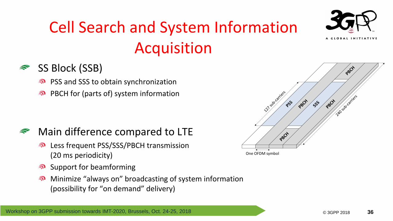
SS Block (SSB)PSS and SSS to obtain synchronization
PBCH for (parts of) system information
Main difference compared to LTELess frequent PSS/SSS/PBCH transmission(20 ms periodicity)
Support for beamforming
Minimize “always on” broadcasting of system information(possibility for “on demand” delivery)
One OFDM symbol
Workshop on 3GPP submission towards IMT-2020, Brussels, Oct. 24-25, 2018
© 3GPP 2012
© 3GPP 2018 37
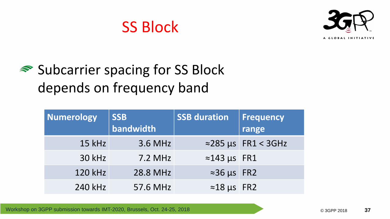
SS Block
Subcarrier spacing for SS Block depends on frequency band
Numerology SSB bandwidth
SSB duration Frequency range
15 kHz 3.6 MHz ≈285 µs FR1 < 3GHz
30 kHz 7.2 MHz ≈143 µs FR1
120 kHz 28.8 MHz ≈36 µs FR2
240 kHz 57.6 MHz ≈18 µs FR2

Workshop on 3GPP submission towards IMT-2020, Brussels, Oct. 24-25, 2018
© 3GPP 2012
© 3GPP 2018 38
SS Block
SS Block not necessarily at the center of the carrier (as in LTE)Reason: allow for a search raster sparser than the frequency raster
Note: SS block not necessarily aligned with the resource block grid
Frequency raster
Search raster
SSB

Workshop on 3GPP submission towards IMT-2020, Brussels, Oct. 24-25, 2018
© 3GPP 2012
© 3GPP 2018 39
SS block and Beam Sweeping
SS burst set Multiple SS blocks in different beams
SB #1 SB #2 SB #L SB #1 SB #2 SB #L
SS burst set period (default 20 ms)
One SS burst set
SB #3
5 ms
Frequency range SS blocks per SS burst set
– 3 GHz 4
3 – 6 GHz 8
mm-wave 64

Workshop on 3GPP submission towards IMT-2020, Brussels, Oct. 24-25, 2018
© 3GPP 2012
© 3GPP 2018 40
Random Access
Four-step random access procedure1 Preamble transmission
2 Random-access response
3, 4 Contention resolution
Device Network
Preamble (PRACH)
RA Response (RAR)
“Message 3”
“Message 4”
Collisionresolution

Workshop on 3GPP submission towards IMT-2020, Brussels, Oct. 24-25, 2018
© 3GPP 2012
© 3GPP 2018 41
Beam Establishment
Different SS block time indices are associated with different RACH time/frequency occasions
SIB1 provides “number of SS-block time indices per RACH time/frequency occasion”
SSB time indices associated with RACH occasions,first in frequency, then in time within a slot, and last in time between slots
RACH slot #0 RACH slot #1
: One RACH occasion

Workshop on 3GPP submission towards IMT-2020, Brussels, Oct. 24-25, 2018
© 3GPP 2012
© 3GPP 2018 42
Supplementary Uplink
System information providesseparate RACH configurations for ‘normal’ and ‘supplementary’ uplinks
threshold for carrier selection
Measure downlink RSRP and select uplink carrier for random accessRSRP above threshold random-access on non-SUL carrier
RSRP below threshold random-access on SUL carrier
Workshop on 3GPP submission towards IMT-2020, Brussels, Oct. 24-25, 2018
© 3GPP 2012
© 3GPP 2018 43
Conclusions
NR addresses a broad range of use cases with a flexible physical layer structure
Key enablers include
Ultra-lean design
Operability in a wide spectrum range
Low latency
Forward compatible design
Advanced multi-antenna techniques

Workshop on 3GPP submission towards IMT-2020, Brussels, Oct. 24-25, 2018
© 3GPP 2012
© 3GPP 2018 44
www.3gpp.org
For more Information:
Search for WIDs at http://www.3gpp.org/specifications/work-plan and http://www.3gpp.org/ftp/Information/WORK_PLAN/ (See excel sheet)