npc-2006 nitrous power controller - induction … nitrous power controller ... the nitrous power...
TRANSCRIPT
NPC-2006
Nitrous Power Controller
Induction Solutions 16121 Flight Path Dr
Brooksville, FL 34604
352-593-5900 Phone 352-593-5901 Fax
email: [email protected]

2
2
What is Included with the NPC‐2006 kit.
NPC‐2006 Nitrous Controller. Wiring Harness with sealed automo ve connectors. 8ga heavy duty solenoid power supply wires. High Amperage Relay. Installa on hardware kit. USB flash drive with PC so ware and a pdf file of the user manual. User Manual
Important Informa on ‐ When using a conven onal style igni on coil (Not Coil on Plug) you must use
Sta c Suppression Igni on Wires with this Controller.
Cau on ‐ Do NOT submerge Controller in liquid or directly wash unit with liquid of any type! (Do NOT spray
when washing vehicle!)
It is the responsibility of the purchaser to follow all guidelines and safety procedures supplied with
this product and any other manufactures product used with this product. It is also the responsibility of the
purchaser to determine compa bility of this device with the vehicle and other components.
Induc on Solu ons assumes no responsibility for damages resul ng from accident, improper installa‐
on, misuse, abuse, improper opera on, lack of reasonable care, or all previously stated reasons due to in‐
compa bility with other manufacturer's products.
Induc on Solu ons assumes no responsibility or liability for damages incurred from the use of prod‐
ucts manufactured or sold by Induc on Solu ons on vehicles used for compe on racing. Induc on Solu ons
neither recommends nor approves the use of products manufactured or sold by Induc on Solu ons on vehi‐
cles which may be driven on public highways or roads, and assumes no responsibility for damages incurred
from such use.
Warranty
Induc on Solu ons warrants to the original purchaser that the controller shall be free from defects in
parts and workmanship under normal use for 180 days from the date of purchase.
Induc on Solu ons obliga on under this warranty is limited to the repair or replacement of any com‐
ponent found to be defec ve when returned postpaid to Induc on Solu ons. The Controller must be re‐
turned with evidence of place and date of purchase or warranty will be void. The warranty will not apply if
the controller has been installed incorrectly, repaired, damaged, or tampered with by misuse, negligence or
accident.

3
3
Contents
So ware Installa on
System Requirements Page 4
Installa on Steps Page 4
Using the So ware
General Overview Page 7
File Menu Page 8
Controller Menu Page 8
Preferences Menu Page 9
Data Menu Page 9
Help Menu Page 9
Stage1 Tab
Setup Page 10
Nitrous Page 11
Fuel Page 13
Stage2 Tab
Setup Page 15
Nitrous Page 16
Fuel Page 18
Timer Stage1 Tab Page 20
Timer Stage2 Tab Page 21
Relay Output Tab Page 22
Configura on Tab Page 23
Data Tab
Data Setup Page 24
Data Chart Page 24
Controller Installa on
Wiring Diagram Page 25
Transmission Brake/Clutch Input Wiring Page 26
RPM/Tachometer Input Wiring Page 26
Stage1 +12 Volt Timer Output Wiring Page 27
Stage2 +12 Volt Timer Output Wiring Page 27
Relay Ground Output Wiring Page 27
Controller Firmware Update
Update Controller Firmware Page 28
Appendix A—Se ng up the controller for a run Page 30
Appendix B—Typical procedure when making a run Page 31
Appendix C—Retrieving data log a er a run Page 32

4
4
System Requirements
Opera ng system
Windows XP Home or Professional with Service Pack 3 installed.
Informa on—if the text is not forma ed or sized correctly with Windows XP opera ng system follow the instruc ons below to adjust the display dots per inch (dpi) se ng.
For Windows XP the screen dpi se ng must be set to default or 96 dpi. 1—Open Display in Control Panel.
2—On the Se ngs tab, click Advanced.
3—On the General tab, in the DPI se ng list, click 96 dots per inch (dpi).
4—Restart your computer when prompted. Windows Vista all versions. Windows 7 all versions. Windows 8.x all versions. Windows 10 all versions.
So ware Installa on Steps
The Nitrous Power Controller so ware is located on the USB flash drive included with the NPC‐2006 kit. Plug the USB flash
drive into an available USB port on the computer.
Important—the so ware must be located and started manually from the USB flash drive. The auto run feature is not imple‐
mented to provide increased security. Please follow the steps below to locate the so ware installa on program.
Please use one of the following methods to open Windows file explorer.
1—Press the Windows logo key + e together.
2—click on the File Explorer icon in the task bar.
3—click Start, point to All Programs, point to Accessories, and then click Windows Explorer.

5
5
Le click on the Induc on Solu ons Drive.
Double click on NPC‐2006_Setup

6
6
Click on the “Next” bu on and follow the installa on wizard prompts as needed.
Important—Please allow the installa on wizard to install the so ware in the default loca on when prompted.
You may be prompted to allow installa on from an unknown publisher, click on “Yes” to con nue with installa on.
Allow the installa on program to complete.
On the Windows desktop you will find a “Nitrous Power Controller” icon.
Double click to start the so ware.
Note—When the so ware is installed a link to start the so ware will also be placed in the program start menu. The installa on pro‐
gram also creates a link to un‐install the so ware. If you no longer wish to have it installed or you need to remove a previous version
before upda ng to a more current version you may select this link from the All Programs/Induc on Solu ons selec on.

7
7
General Overview
Menu bar
Toolbar menu Hover mouse cursor over icon for informa on. Tabbed naviga on bu ons
Progress bar– this pro‐
vides visual feedback for
read and write opera ons
to the controller through
the USB interface.
USB connec on status– this
indicates a valid USB connec‐
on has been established with
the controller.
Firmware version—this indi‐
cates the current firmware
installed in the controller.
Current setup file in use.
Click on the “I” bu ons for help.

8
8
File Menu
Open File—open setup file that has been previously saved to the computer.
Save File—save current setup file to computer. This op on saves the current setup data from the Nitrous Power
Controller so ware. It does not save the setup data from the controller to the computer.
Save As—save current setup file to computer with the op on to save as a copy with a different name.
Exit—Exit and close the Nitrous Power Controller so ware.
Controller Menu
Important—the controller must be connected to the computer with the USB cable and the controller must be
powered up to use the following menu selec ons. Only the Switched +12V power (key on) needs to be on for
USB communica on, the arming switch should be in the off posi on.
Always allow the progress bar in the lower le corner to complete a er star ng a download or upload to the
controller.
Download Setup from Controller—read setup data from the controller to the Nitrous Power Controller so ‐
ware. Note—a er downloading the setup data from the controller you may use the File Menu, Save File selec‐
on to save the setup data to a file on the computer.
Upload Setup to Controller—write current setup data from the Nitrous Power Controller so ware to the con‐
troller. Note—to load a saved setup file from the computer to the controller, first use File Menu, Open File to
load the file. A er opening the file use this selec on to write the setup to the controller.
Download Data Log from Controller—read data log informa on from the controller. This selec on will read the
most recent data log informa on from the controller. Note—the controller will retain the last data logged even
if the controller is powered off.
Update Controller Firmware—load a new firmware image file into the controller. The firmware is the opera ng
system for the controller. When a new and/or updated version is released that has addi onal features, or a fix
for an unforeseen issue, this selec on is used to apply the update to the controller.

9
9
Preferences Menu
Load Last File on Startup—if the op on is selected (checkmark present) the most recent setup file will be auto‐
ma cally opened when the Nitrous Power Controller so ware is launched. Note—if the file does not exist or
has been moved to a new loca on the default setup will opened.
Data Menu
Help Menu
Open Data Log File—open a data log file that has been previously saved to the computer.
Save Data Log File—save data log informa on to a file on the computer. To save data log informa on from the
controller to a file. First use Controller Menu, Download Data Log from Controller and then use this selec on to
save the data log informa on to the computer.
About—this selec on displays a small window with so ware version informa on.

10
10
Stage1 Tab—Setup
Stage1 Delay Timer ‐ this se ng sets the delay me in seconds before Stage1 starts a er Ac va on.
Valid range ‐ 0.000 to 10.000 in .001 second increments.
Note—If the RPM window feature is enabled and the engine
is not running the solenoids can be dry fired for tes ng. Once
an RPM signal is present the solenoids will only fire at the
desired RPM range.
Enable Stage1 RPM control ‐ this se ng enables a RPM Window func on for Stage1.
Stage1 Minimum RPM ‐ this se ng controls the minimum engine RPM that must be achieved before Stage1 will turn On. A se ng of
0 will disable the Minimum RPM func on and the Maximum RPM se ng will be used to turn off Stage1 if the engine RPM exceeds the
se ng.
Valid range ‐ 0 to 15,900 RPM in 10 RPM Increments.
Stage1 Maximum RPM ‐ this se ng controls the maximum engine RPM that Stage1 remains On. When the engine RPM exceeds this
se ng Stage1 will be turned Off. The Maximum RPM must be at least 100 RPM greater than the Minimum RPM se ng.
Valid range ‐ 1000 to 16,000 RPM in 10 RPM increments.
Synchronize Solenoid Pulse Frequency
All Solenoids use Stage1 Nitrous pulse frequency (hertz) ‐ this se ng forces all solenoid outputs to operate at the Stage1 Nitrous Sole‐
noid Pulse Frequency se ng. The controls to adjust individual solenoid output frequencies will be disabled when this se ng is On.
Stage1 Synchronize Pulse Frequency ‐ the Stage1 nitrous and fuel solenoids can be configured to func on at the nitrous solenoid fre‐
quency only (both Stage1 outputs synchronized). Or the Stage1 nitrous and fuel solenoid output frequencies may be set independent‐
ly.
IMPORTANT ‐ if you choose to operate the nitrous and fuel solenoids at different frequencies (hertz) you MUST insure that both sole‐
noids operate as desired in the delivery of nitrous and fuel to the engine!
Informa on ‐ the solenoid pulse frequency (hertz) is how many mes per second the solenoids open and close when not at 0 or 100
percent opera on. Example ‐ pulse frequency set to 10 hertz and 50 percent, the solenoids would open and close 10 mes per sec‐
ond. Total me for each pulse = 1 / 10 = .1 second, total me solenoid would be on = .1 * .50% = .05 second.
There are many different styles of solenoids available and they will react differently to changes in the opera ng frequency. It is up to
the user to verify that the solenoids are opening properly with the se ngs used for opera on
As a general rule a lower frequency se ng will allow a solenoid to open properly when a high nitrous pressure is used and a low
star ng percentage. This is just a general rule, test your se ngs!

11
11
Stage1 Tab—Nitrous Graph
Graph Control Edi ng
Le click on a data point to enable edi ng for that data point. Le click and drag to adjust the value of the selected data
point. Click on the graph or another data point to disable the current edit point.
Double le click on a data point to set an anchor point, once the anchor point is set le click on another data point and
when the value is changed the graph will auto fill between the anchor point and the current edit point. Click on the anchor
point or anywhere in the graph to clear the anchor point.
Once the graph is the ac ve control (click on graph) the keyboard may also be used to edit the data points.
CTRL+S ‐ set edit point to center of graph data.
Le and Right keys ‐ move the current edit point le or right.
Up Arrow and Down Arrow ‐ adjust current data point up or down in 1% increments.
CTRL + Up Arrow and CTRL + Down Arrow ‐ adjust current data point up or down in .1% increments.
ENTER ‐ set anchor point at current edit point. No ac on if there is no current edit point.
ESC ‐ clear edit and anchor point(s).
Note—the Stage1 Fuel graph ramp will appear in the background to provide a visual reference.
Edit point
Use this feature to Copy the contents of the graph control to other graph
controls.
12
12
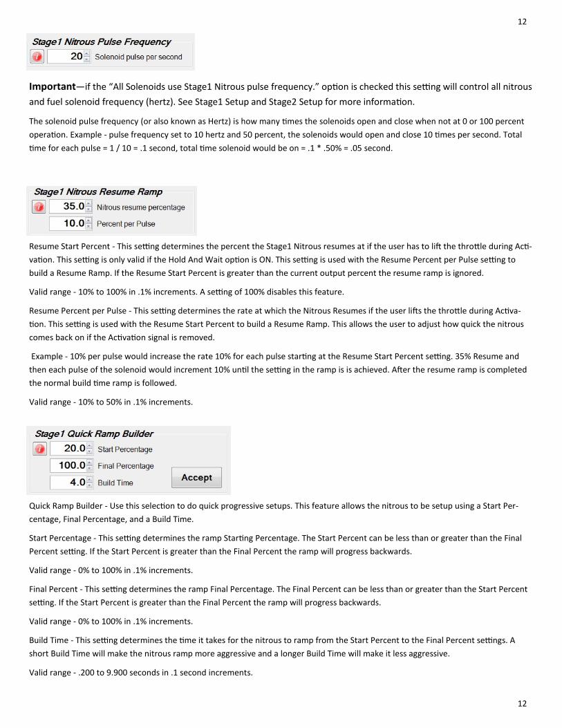
Important—if the “All Solenoids use Stage1 Nitrous pulse frequency.” op on is checked this se ng will control all nitrous
and fuel solenoid frequency (hertz). See Stage1 Setup and Stage2 Setup for more informa on.
The solenoid pulse frequency (or also known as Hertz) is how many mes the solenoids open and close when not at 0 or 100 percent
opera on. Example ‐ pulse frequency set to 10 hertz and 50 percent, the solenoids would open and close 10 mes per second. Total
me for each pulse = 1 / 10 = .1 second, total me solenoid would be on = .1 * .50% = .05 second.
Resume Start Percent ‐ This se ng determines the percent the Stage1 Nitrous resumes at if the user has to li the thro le during Ac ‐
va on. This se ng is only valid if the Hold And Wait op on is ON. This se ng is used with the Resume Percent per Pulse se ng to
build a Resume Ramp. If the Resume Start Percent is greater than the current output percent the resume ramp is ignored.
Valid range ‐ 10% to 100% in .1% increments. A se ng of 100% disables this feature.
Resume Percent per Pulse ‐ This se ng determines the rate at which the Nitrous Resumes if the user li s the thro le during Ac va‐
on. This se ng is used with the Resume Start Percent to build a Resume Ramp. This allows the user to adjust how quick the nitrous
comes back on if the Ac va on signal is removed.
Example ‐ 10% per pulse would increase the rate 10% for each pulse star ng at the Resume Start Percent se ng. 35% Resume and
then each pulse of the solenoid would increment 10% un l the se ng in the ramp is is achieved. A er the resume ramp is completed
the normal build me ramp is followed.
Valid range ‐ 10% to 50% in .1% increments.
Quick Ramp Builder ‐ Use this selec on to do quick progressive setups. This feature allows the nitrous to be setup using a Start Per‐
centage, Final Percentage, and a Build Time.
Start Percentage ‐ This se ng determines the ramp Star ng Percentage. The Start Percent can be less than or greater than the Final
Percent se ng. If the Start Percent is greater than the Final Percent the ramp will progress backwards.
Valid range ‐ 0% to 100% in .1% increments.
Final Percent ‐ This se ng determines the ramp Final Percentage. The Final Percent can be less than or greater than the Start Percent
se ng. If the Start Percent is greater than the Final Percent the ramp will progress backwards.
Valid range ‐ 0% to 100% in .1% increments.
Build Time ‐ This se ng determines the me it takes for the nitrous to ramp from the Start Percent to the Final Percent se ngs. A
short Build Time will make the nitrous ramp more aggressive and a longer Build Time will make it less aggressive.
Valid range ‐ .200 to 9.900 seconds in .1 second increments.
13
13
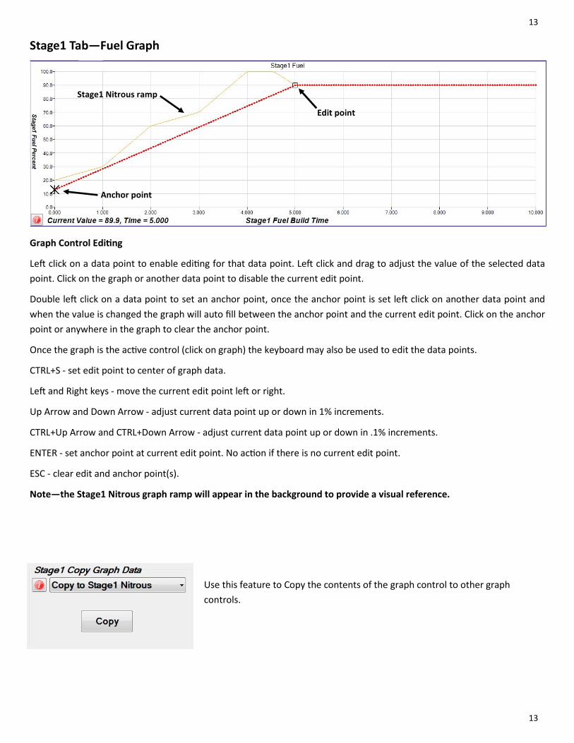
Stage1 Tab—Fuel Graph
Graph Control Edi ng
Le click on a data point to enable edi ng for that data point. Le click and drag to adjust the value of the selected data
point. Click on the graph or another data point to disable the current edit point.
Double le click on a data point to set an anchor point, once the anchor point is set le click on another data point and
when the value is changed the graph will auto fill between the anchor point and the current edit point. Click on the anchor
point or anywhere in the graph to clear the anchor point.
Once the graph is the ac ve control (click on graph) the keyboard may also be used to edit the data points.
CTRL+S ‐ set edit point to center of graph data.
Le and Right keys ‐ move the current edit point le or right.
Up Arrow and Down Arrow ‐ adjust current data point up or down in 1% increments.
CTRL+Up Arrow and CTRL+Down Arrow ‐ adjust current data point up or down in .1% increments.
ENTER ‐ set anchor point at current edit point. No ac on if there is no current edit point.
ESC ‐ clear edit and anchor point(s).
Note—the Stage1 Nitrous graph ramp will appear in the background to provide a visual reference.
Anchor point
Edit point
Stage1 Nitrous ramp
Use this feature to Copy the contents of the graph control to other graph
controls.

14
14
Important—the “All Solenoids use Stage1 Nitrous pulse frequency.” op on must be un‐checked (off) When this feature is
enable the Stage2 solenoid frequency (hertz) can be adjusted independently of the Stage1 frequency (hertz).
The solenoid pulse frequency (or also known as Hertz) is how many mes the solenoids open and close when not at 0 or 100 percent
opera on. Example ‐ pulse frequency set to 10 hertz and 50 percent, the solenoids would open and close 10 mes per second. Total
me for each pulse = 1 / 10 = .1 second, total me solenoid would be on = .1 * .50% = .05 second.
Resume Start Percent ‐ This se ng determines the percent the Stage1 Fuel resumes at if the user has to li the thro le during Ac va‐
on. This se ng is only valid if the Hold And Wait op on is ON. This se ng is used with the Resume Percent per Pulse se ng to build
a Resume Ramp. If the Resume Start Percent is greater than the current output percent the Resume Ramp is ignored.
Valid range ‐ 10% to 100% in .1% increments. A se ng of 100% disables this feature.
Resume Percent per Pulse ‐ This se ng determines the rate at which the Fuel Resumes if the user li s the thro le during Ac va on.
This se ng is used with the Resume Start Percent to build a Resume Ramp. This allows the user to adjust how quick the fuel comes
back on if the Ac va on signal is removed.
Example ‐ 10% per pulse would increase the rate 10% for each pulse star ng at the Resume Start Percent se ng. 35% Resume and
then each pulse of the solenoid would increment 10% un l the se ng in the ramp is is achieved. A er the resume ramp is completed
the normal build me ramp is followed.
Valid range ‐ 10% to 50% in .1% increments.
Quick Ramp Builder ‐ Use this selec on to do quick progressive setups. This feature allows the fuel to be setup using a Start Percent‐
age, Final Percentage, and a Build Time.
Start Percentage ‐ This se ng determines the ramp Star ng Percentage. The Start Percent can be less than or greater than the Final
Percent se ng. If the Start Percent is greater than the Final Percent the ramp will progress backwards.
Valid range ‐ 0% to 100% in .1% increments.
Final Percent ‐ This se ng determines the ramp Final Percentage. The Final Percent can be less than or greater than the Start Percent
se ng. If the Start Percent is greater than the Final Percent the ramp will progress backwards.
Valid range ‐ 0% to 100% in .1% increments.
Build Time ‐ This se ng determines the me it takes for the fuel to ramp from the Start Percent to the Final Percent se ngs. A short
Build Time will make the fuel ramp more aggressive and a longer Build Time will make it less aggressive.
Valid range ‐ .200 to 9.900 seconds in .1 second increments.
15
15
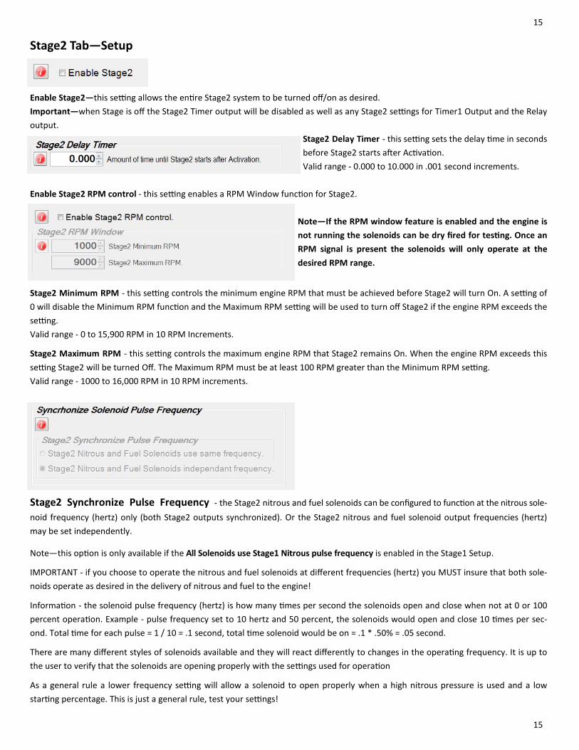
Stage2 Tab—Setup
Enable Stage2—this se ng allows the en re Stage2 system to be turned off/on as desired.
Important—when Stage is off the Stage2 Timer output will be disabled as well as any Stage2 se ngs for Timer1 Output and the Relay
output.
Stage2 Delay Timer ‐ this se ng sets the delay me in seconds
before Stage2 starts a er Ac va on.
Valid range ‐ 0.000 to 10.000 in .001 second increments.
Enable Stage2 RPM control ‐ this se ng enables a RPM Window func on for Stage2.
Note—If the RPM window feature is enabled and the engine is
not running the solenoids can be dry fired for tes ng. Once an
RPM signal is present the solenoids will only operate at the
desired RPM range.
Stage2 Minimum RPM ‐ this se ng controls the minimum engine RPM that must be achieved before Stage2 will turn On. A se ng of
0 will disable the Minimum RPM func on and the Maximum RPM se ng will be used to turn off Stage2 if the engine RPM exceeds the
se ng.
Valid range ‐ 0 to 15,900 RPM in 10 RPM Increments.
Stage2 Maximum RPM ‐ this se ng controls the maximum engine RPM that Stage2 remains On. When the engine RPM exceeds this
se ng Stage2 will be turned Off. The Maximum RPM must be at least 100 RPM greater than the Minimum RPM se ng.
Valid range ‐ 1000 to 16,000 RPM in 10 RPM increments.
Stage2 Synchronize Pulse Frequency ‐ the Stage2 nitrous and fuel solenoids can be configured to func on at the nitrous sole‐
noid frequency (hertz) only (both Stage2 outputs synchronized). Or the Stage2 nitrous and fuel solenoid output frequencies (hertz)
may be set independently.
Note—this op on is only available if the All Solenoids use Stage1 Nitrous pulse frequency is enabled in the Stage1 Setup.
IMPORTANT ‐ if you choose to operate the nitrous and fuel solenoids at different frequencies (hertz) you MUST insure that both sole‐
noids operate as desired in the delivery of nitrous and fuel to the engine!
Informa on ‐ the solenoid pulse frequency (hertz) is how many mes per second the solenoids open and close when not at 0 or 100
percent opera on. Example ‐ pulse frequency set to 10 hertz and 50 percent, the solenoids would open and close 10 mes per sec‐
ond. Total me for each pulse = 1 / 10 = .1 second, total me solenoid would be on = .1 * .50% = .05 second.
There are many different styles of solenoids available and they will react differently to changes in the opera ng frequency. It is up to
the user to verify that the solenoids are opening properly with the se ngs used for opera on
As a general rule a lower frequency se ng will allow a solenoid to open properly when a high nitrous pressure is used and a low
star ng percentage. This is just a general rule, test your se ngs!

16
16
Stage2 Tab—Nitrous Graph
Graph Control Edi ng
Le click on a data point to enable edi ng for that data point. Le click and drag to adjust the value of the selected data
point. Click on the graph or another data point to disable the current edit point.
Double le click on a data point to set an anchor point, once the anchor point is set le click on another data point and
when the value is changed the graph will auto fill between the anchor point and the current edit point. Click on the anchor
point or anywhere in the graph to clear the anchor point.
Once the graph is the ac ve control (click on graph) the keyboard may also be used to edit the data points.
CTRL+S ‐ set edit point to center of graph data.
Le and Right keys ‐ move the current edit point le or right.
Up Arrow and Down Arrow ‐ adjust current data point up or down in 1% increments.
CTRL+Up Arrow and CTRL+Down Arrow ‐ adjust current data point up or down in .1% increments.
ENTER ‐ set anchor point at current edit point. No ac on if there is no current edit point.
ESC ‐ clear edit and anchor point(s).
Note—the Stage2 Fuel graph ramp will appear in the background to provide a visual reference.
Stage2 Fuel ramp
Edit point
Anchor point
Use this feature to Copy the contents of the graph control to other graph
controls.
17
17
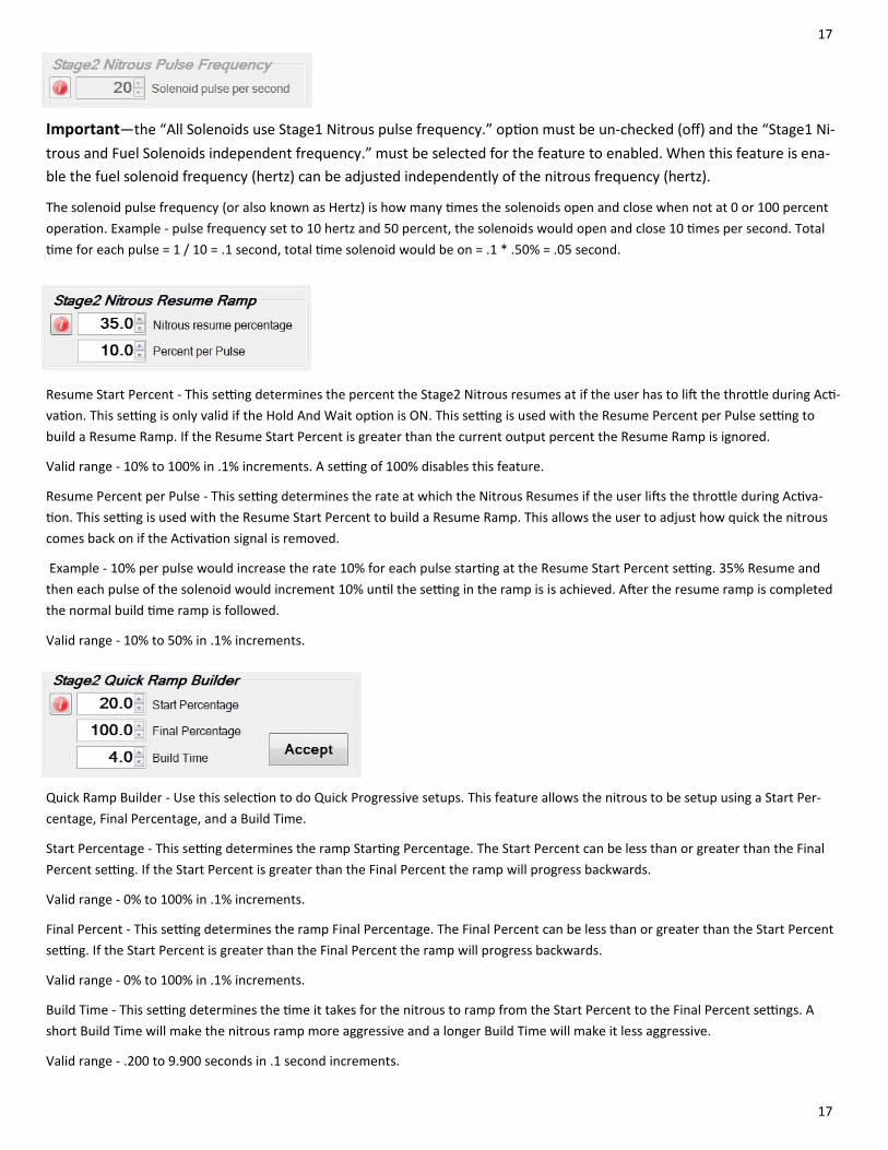
Important—the “All Solenoids use Stage1 Nitrous pulse frequency.” op on must be un‐checked (off) and the “Stage1 Ni‐
trous and Fuel Solenoids independent frequency.” must be selected for the feature to enabled. When this feature is ena‐
ble the fuel solenoid frequency (hertz) can be adjusted independently of the nitrous frequency (hertz).
The solenoid pulse frequency (or also known as Hertz) is how many mes the solenoids open and close when not at 0 or 100 percent
opera on. Example ‐ pulse frequency set to 10 hertz and 50 percent, the solenoids would open and close 10 mes per second. Total
me for each pulse = 1 / 10 = .1 second, total me solenoid would be on = .1 * .50% = .05 second.
Resume Start Percent ‐ This se ng determines the percent the Stage2 Nitrous resumes at if the user has to li the thro le during Ac ‐
va on. This se ng is only valid if the Hold And Wait op on is ON. This se ng is used with the Resume Percent per Pulse se ng to
build a Resume Ramp. If the Resume Start Percent is greater than the current output percent the Resume Ramp is ignored.
Valid range ‐ 10% to 100% in .1% increments. A se ng of 100% disables this feature.
Resume Percent per Pulse ‐ This se ng determines the rate at which the Nitrous Resumes if the user li s the thro le during Ac va‐
on. This se ng is used with the Resume Start Percent to build a Resume Ramp. This allows the user to adjust how quick the nitrous
comes back on if the Ac va on signal is removed.
Example ‐ 10% per pulse would increase the rate 10% for each pulse star ng at the Resume Start Percent se ng. 35% Resume and
then each pulse of the solenoid would increment 10% un l the se ng in the ramp is is achieved. A er the resume ramp is completed
the normal build me ramp is followed.
Valid range ‐ 10% to 50% in .1% increments.
Quick Ramp Builder ‐ Use this selec on to do Quick Progressive setups. This feature allows the nitrous to be setup using a Start Per‐
centage, Final Percentage, and a Build Time.
Start Percentage ‐ This se ng determines the ramp Star ng Percentage. The Start Percent can be less than or greater than the Final
Percent se ng. If the Start Percent is greater than the Final Percent the ramp will progress backwards.
Valid range ‐ 0% to 100% in .1% increments.
Final Percent ‐ This se ng determines the ramp Final Percentage. The Final Percent can be less than or greater than the Start Percent
se ng. If the Start Percent is greater than the Final Percent the ramp will progress backwards.
Valid range ‐ 0% to 100% in .1% increments.
Build Time ‐ This se ng determines the me it takes for the nitrous to ramp from the Start Percent to the Final Percent se ngs. A
short Build Time will make the nitrous ramp more aggressive and a longer Build Time will make it less aggressive.
Valid range ‐ .200 to 9.900 seconds in .1 second increments.
18
18
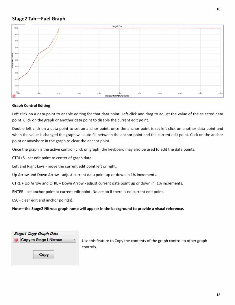
Stage2 Tab—Fuel Graph
Graph Control Edi ng
Le click on a data point to enable edi ng for that data point. Le click and drag to adjust the value of the selected data
point. Click on the graph or another data point to disable the current edit point.
Double le click on a data point to set an anchor point, once the anchor point is set le click on another data point and
when the value is changed the graph will auto fill between the anchor point and the current edit point. Click on the anchor
point or anywhere in the graph to clear the anchor point.
Once the graph is the ac ve control (click on graph) the keyboard may also be used to edit the data points.
CTRL+S ‐ set edit point to center of graph data.
Le and Right keys ‐ move the current edit point le or right.
Up Arrow and Down Arrow ‐ adjust current data point up or down in 1% increments.
CTRL + Up Arrow and CTRL + Down Arrow ‐ adjust current data point up or down in .1% increments.
ENTER ‐ set anchor point at current edit point. No ac on if there is no current edit point.
ESC ‐ clear edit and anchor point(s).
Note—the Stage2 Nitrous graph ramp will appear in the background to provide a visual reference.
Use this feature to Copy the contents of the graph control to other graph
controls.
19
19
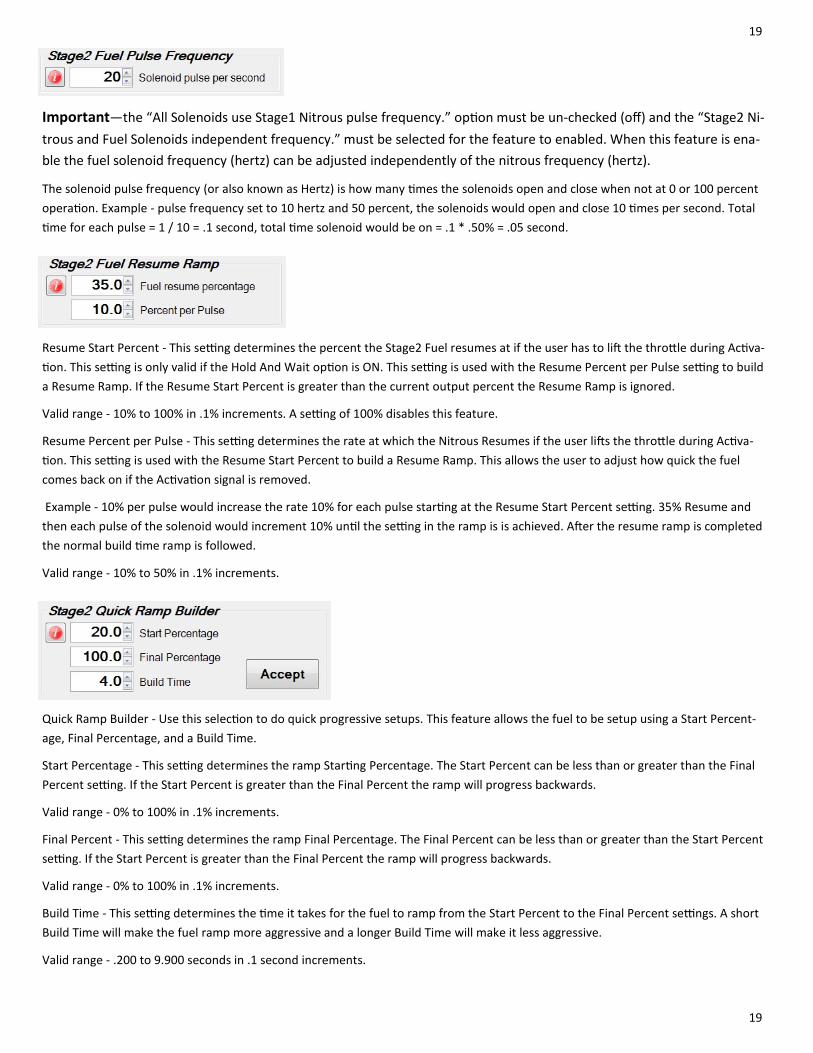
Important—the “All Solenoids use Stage1 Nitrous pulse frequency.” op on must be un‐checked (off) and the “Stage2 Ni‐
trous and Fuel Solenoids independent frequency.” must be selected for the feature to enabled. When this feature is ena‐
ble the fuel solenoid frequency (hertz) can be adjusted independently of the nitrous frequency (hertz).
The solenoid pulse frequency (or also known as Hertz) is how many mes the solenoids open and close when not at 0 or 100 percent
opera on. Example ‐ pulse frequency set to 10 hertz and 50 percent, the solenoids would open and close 10 mes per second. Total
me for each pulse = 1 / 10 = .1 second, total me solenoid would be on = .1 * .50% = .05 second.
Resume Start Percent ‐ This se ng determines the percent the Stage2 Fuel resumes at if the user has to li the thro le during Ac va‐
on. This se ng is only valid if the Hold And Wait op on is ON. This se ng is used with the Resume Percent per Pulse se ng to build
a Resume Ramp. If the Resume Start Percent is greater than the current output percent the Resume Ramp is ignored.
Valid range ‐ 10% to 100% in .1% increments. A se ng of 100% disables this feature.
Resume Percent per Pulse ‐ This se ng determines the rate at which the Nitrous Resumes if the user li s the thro le during Ac va‐
on. This se ng is used with the Resume Start Percent to build a Resume Ramp. This allows the user to adjust how quick the fuel
comes back on if the Ac va on signal is removed.
Example ‐ 10% per pulse would increase the rate 10% for each pulse star ng at the Resume Start Percent se ng. 35% Resume and
then each pulse of the solenoid would increment 10% un l the se ng in the ramp is is achieved. A er the resume ramp is completed
the normal build me ramp is followed.
Valid range ‐ 10% to 50% in .1% increments.
Quick Ramp Builder ‐ Use this selec on to do quick progressive setups. This feature allows the fuel to be setup using a Start Percent‐
age, Final Percentage, and a Build Time.
Start Percentage ‐ This se ng determines the ramp Star ng Percentage. The Start Percent can be less than or greater than the Final
Percent se ng. If the Start Percent is greater than the Final Percent the ramp will progress backwards.
Valid range ‐ 0% to 100% in .1% increments.
Final Percent ‐ This se ng determines the ramp Final Percentage. The Final Percent can be less than or greater than the Start Percent
se ng. If the Start Percent is greater than the Final Percent the ramp will progress backwards.
Valid range ‐ 0% to 100% in .1% increments.
Build Time ‐ This se ng determines the me it takes for the fuel to ramp from the Start Percent to the Final Percent se ngs. A short
Build Time will make the fuel ramp more aggressive and a longer Build Time will make it less aggressive.
Valid range ‐ .200 to 9.900 seconds in .1 second increments.

20
20
Timer Stage1 Tab
Stage1 Timer, Timing Retard Control ‐ this se ng configures the Stage1 Timer, +12V output to be On whenever Stage1 Nitrous
is On (Solenoids func oning). Check to enable.
If this se ng is Off then the Timer1 output can be configured by selec ng which control parameters are used to turn On the output.
When more than one control parameter has been selected all must meet the condi ons as configured before the output will func on.
Example ‐ Ac va on Input Enabled and RPM Enabled, RPM On = 2000 and RPM Off = 4000, the Timer1 output will only be on when the
Ac va on Input is ac ve and the engine rpm is between 2000 and 4000 rpm.
This output supplies +12V when On.
This output may be used to drive an external relay with a load of no more than 1 amp. The relay can then be used to control another
stage of nitrous with no progressive ramp.
Timer Stage1 Configura on ‐ check to enable which control parameters are used to deter‐
mine when the Stage1 Timer +12V output will be On. This output supplies +12V when On.
Any op ons that are selected are combined to determine if the output should be on or off.
Note—the “Timing Retard Control” must be un‐checked (off) for these features to
be enabled.
Delay Timer ‐ these se ngs control the Delay me and On me
for the Timer output.
Valid range ‐ 0.000 to 10.000 in .001 Second increments.
Engine RPM ‐ these se ngs control the output based on Engine
RPM.
Valid range ‐ 0 to 16000 in 10 RPM increments.
Stage2 Nitrous Percent ‐ these se ngs control the output
based on Stage2 Nitrous Percent.
Valid range ‐ 0.0 to 100.0 in .1 Percent increments.
Stage2 Fuel Percent ‐ these se ngs control the output based on
Stage2 Fuel Percent.
Valid range ‐ 0.0 to 100.0 in .1 Percent increments.
Stage1 Nitrous Percent ‐
these se ngs control the
output based on Stage1
Nitrous Percent.
Valid range ‐ 0.0 to 100.0
in .1 Percent increments.
Stage1 Fuel Percent ‐ these
se ngs control the output
based on Stage1 Fuel Per‐
cent.
Valid range ‐ 0.0 to 100.0
in .1 Percent increments.
21
21
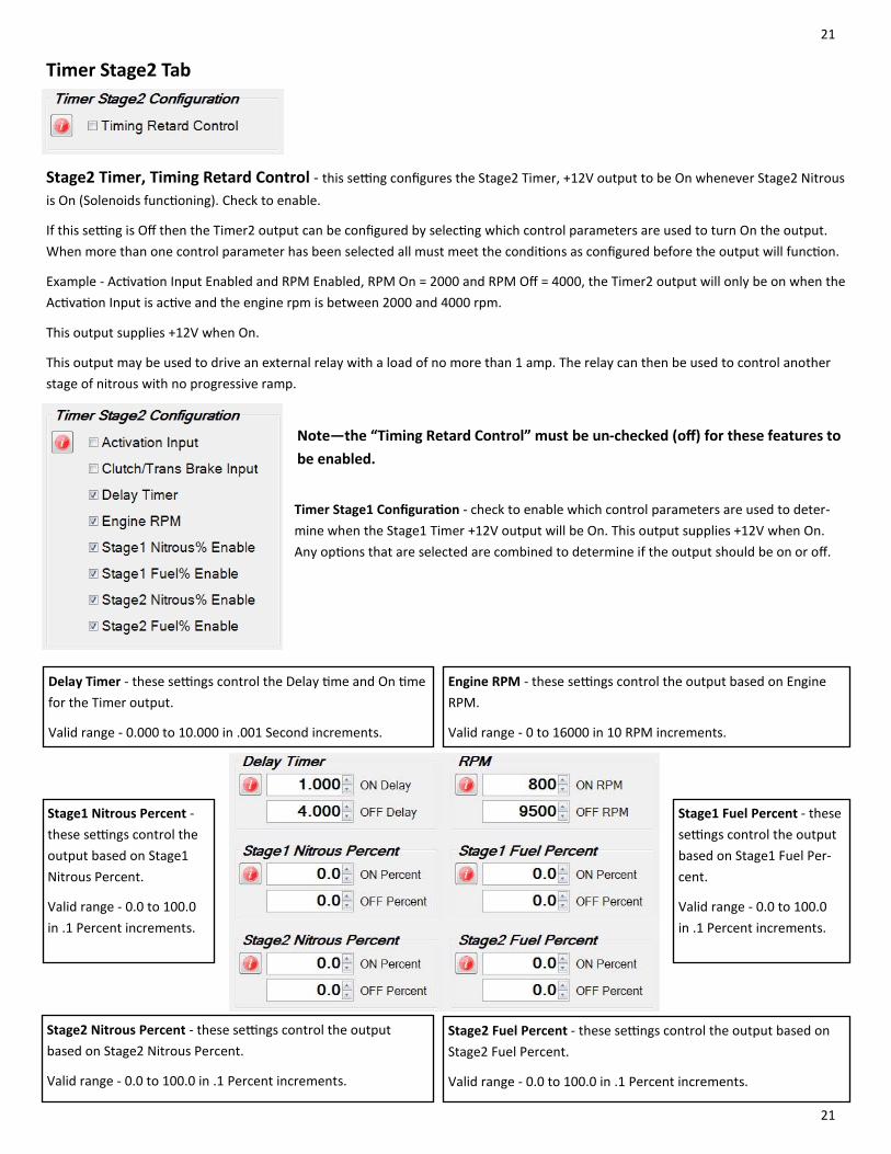
Timer Stage2 Tab
Stage2 Timer, Timing Retard Control ‐ this se ng configures the Stage2 Timer, +12V output to be On whenever Stage2 Nitrous
is On (Solenoids func oning). Check to enable.
If this se ng is Off then the Timer2 output can be configured by selec ng which control parameters are used to turn On the output.
When more than one control parameter has been selected all must meet the condi ons as configured before the output will func on.
Example ‐ Ac va on Input Enabled and RPM Enabled, RPM On = 2000 and RPM Off = 4000, the Timer2 output will only be on when the
Ac va on Input is ac ve and the engine rpm is between 2000 and 4000 rpm.
This output supplies +12V when On.
This output may be used to drive an external relay with a load of no more than 1 amp. The relay can then be used to control another
stage of nitrous with no progressive ramp.
Note—the “Timing Retard Control” must be un‐checked (off) for these features to
be enabled.
Timer Stage1 Configura on ‐ check to enable which control parameters are used to deter‐
mine when the Stage1 Timer +12V output will be On. This output supplies +12V when On.
Any op ons that are selected are combined to determine if the output should be on or off.
Delay Timer ‐ these se ngs control the Delay me and On me
for the Timer output.
Valid range ‐ 0.000 to 10.000 in .001 Second increments.
Engine RPM ‐ these se ngs control the output based on Engine
RPM.
Valid range ‐ 0 to 16000 in 10 RPM increments.
Stage2 Nitrous Percent ‐ these se ngs control the output
based on Stage2 Nitrous Percent.
Valid range ‐ 0.0 to 100.0 in .1 Percent increments.
Stage2 Fuel Percent ‐ these se ngs control the output based on
Stage2 Fuel Percent.
Valid range ‐ 0.0 to 100.0 in .1 Percent increments.
Stage1 Nitrous Percent ‐
these se ngs control the
output based on Stage1
Nitrous Percent.
Valid range ‐ 0.0 to 100.0
in .1 Percent increments.
Stage1 Fuel Percent ‐ these
se ngs control the output
based on Stage1 Fuel Per‐
cent.
Valid range ‐ 0.0 to 100.0
in .1 Percent increments.

22
22
Relay Output Tab
Relay Output Configura on ‐ check to enable which control parameters are used to deter‐
mine when the Relay output will be On.
This output provides a Ground when it is On.
Maximum current draw is 1 amp.
Delay Timer ‐ these se ngs control the Delay me and On me
for the Relay output.
Valid range ‐ 0.000 to 10.000 in .001 Second increments.
Engine RPM ‐ these se ngs control the output based on Engine
RPM.
Valid range ‐ 0 to 16000 in 10 RPM increments.
Stage2 Nitrous Percent ‐ these se ngs control the output
based on Stage2 Nitrous Percent.
Valid range ‐ 0.0 to 100.0 in .1 Percent increments.
Stage2 Fuel Percent ‐ these se ngs control the output based on
Stage2 Fuel Percent.
Valid range ‐ 0.0 to 100.0 in .1 Percent increments.
Stage1 Nitrous Percent ‐
these se ngs control the
output based on Stage1
Nitrous Percent.
Valid range ‐ 0.0 to 100.0
in .1 Percent increments.
Stage1 Fuel Percent ‐ these
se ngs control the output
based on Stage1 Fuel Per‐
cent.
Valid range ‐ 0.0 to 100.0
in .1 Percent increments.

23
23
Configura on Tab
Main Timer ‐ This se ng controls the Main Timer period. This controls the total me elapsed before a System Timeout occurs. This
limits the total amount of me the solenoids can be On if the Ac va on signal is never removed.
Once the Main Timer has med out the Ac va on signal must be removed before the controller may be ac vated again.
Valid range ‐ 20 to 300 in 1 second increments.
Hold & Wait ‐ This se ng allows the Progressive system to Hold & Wait when the Ac va on signal is removed.
Example ‐ the thro le is li ed due to wheel spin (Ac va on signal removed). If Hold & Wait is ON the Progressive system will resume
at the point where the thro le was li ed. See Nitrous and Fuel Resume Ramp for addi onal resume features.
If this op on is OFF the Progressive system and All Timers will reset each me the Ac va on is removed.
Clutch/Trans Brake Input Delay Timer ‐ this se ng controls how long the Clutch/Trans Brake input must be On before accep ng the
signal. The clutch input hold delay se ng is ignored un l the controller is Ac vated.
Before the controller is Ac vated the clutch input is recognized in real me with no delay.
This se ng could be used to ignore shi s with a manual transmission (1 second) or a very low se ng would act as noise filter to ignore
spurious signals (.005 second).
If a clutch input signal is recieved and accepted a er the controller is ac vated the system will turn off the progressive system and m‐
ers. This would allow the nitrous to be turned Off during a shi and resumed when the clutch is released.
Valid range ‐ 0.000 to 1.000 in .001 second increments. (0.000 turns this func on OFF)
Tach Input Pulse Per Revolu on ‐ this se ng determines the number of Tach Pulses per revolu on of the cranksha .
Example ‐ if the Tach Signal input is connected to a common V8 engine mul ‐spark igni on controller a se ng of 4 Pulse per Revolu‐on would be used.
Common se ngs are,
1 Pulse per Two Revolu ons = modern coil on plug systems with white wire connected to single coil wire.
1 Pulse per Revolu on = single cylinder engine and some twin cylinder motorcycle engines.
2 Pulse per Revolu on = 4 cylinder car and motorcycle engines.
3 Pulse per Revolu on = 6 cylinder engines.
4 Pulse per Revolu on = 8 cylinder engines.
5 Pulse per Revolu on = 10 cylinder engines.

24
24
Data Tab – Data Setup Data Log Ac va on ‐ these se ngs determine when the controller begins recording data.
If more than one op on is selected ALL condi ons must be met before a new data log will
start.
Example ‐ Ac va on input and Clutch/Trans Brake input both selected, a new data log will
begin recording when both inputs are ac ve. This would be a typical setup when making a
pass at the track. Once staged the Clutch/Trans Brake would be on, then when the wide
open thro le switch goes ac ve the controller would begin a new data log..
Example if on a chassis dyno and the Clutch/Trans Brake input is not being used you would
want to have only Ac va on input selected to start a new data log..
RPM ‐ this se ng determines the Engine RPM when the controller begins recording data.
Valid range ‐ 1,000 to 10,000 in 10 RPM increments.
Data Tab – Data Chart
Data Log Navaiga on and keyboard shortcut keys.
Right and Le arrow keys ‐ pan cursor right and le , use SHIFT + Right/Le and CTRL + Right/Le keys to pan by small increments.
I ‐ Zoom in, O ‐ Zoom out.
Le click on chart tle at top of window to turn chart ON/OFF in the graph.
Right click on chart tle at top of window to set chart op ons.
Le click on current chart tle (top right side of graph) to select next chart.
Right click on graph to set run start and end me.
To change the grouping of chart tles, hover mouse over top of graph and when the cursor changes, le click and drag graph height up
or down as desired.
The graph se ngs will be saved when the program is closed and reloaded when the program is launched.
Click tle to turn on/off Drag chart height here to adjust tle display

25
25
Wiring Diagram
+12V Input Required
This relay is included with the kit.

26
26
Transmission Brake/Clutch Input Wiring
Important Informa on—when then Trans‐Brake/Clutch input is ON the Ac va on input will be ignored un l the transmission brake or
clutch is released. This keeps the nitrous OFF when the Trans‐Brake/Clutch input is ON and the thro le is wide open.
RPM/Tachometer Input Wiring Typical a ermarket CDI igni on tachometer wiring. See igni on manufacturer instruc ons for more informa on.
Cau on—never connect the white tach signal wire directly to the coil nega ve wire with a mul ‐spark igni on.
Connect white tach signal wire
here when not using a CDI or
mul ‐spark igni on.
(white tach signal wire)
The tach input signal can also be connected to a +5 volt or +12 volt square wave signal on newer fuel injected vehicles. You will need
to research the vehicle in ques on and check to see if the ECM provides a tach (rpm) signal. You may also purchase an a ermarket
tach signal adapter if needed.
Connect white tach signal wire here.

27
27
Stage1 +12 Volt Timer Output Wiring
Stage2 +12 Volt Timer Output Wiring
Relay Ground Output Wiring
This output provides +12 volt at 1 amp maximum, there is an internal 1k ohm resistor to ground so the output is not floa ng when in
the off state. If your igni on and/or igni on ming controller is ac vated by a +12 volt signal the 20ga Blue Stage1 Output wire can be
connected directly to retard ac va on.
Important—always test for proper ming retard opera on before spraying nitrous! You can use a ming light or a data logger if it is
equipped to log igni on ming. Do a dry test (engine running, solenoids unplugged) to confirm proper ming retard.
This output provides +12 volt at 1 amp maximum, there is an internal 1k ohm resistor to ground so the output is not floa ng when in
the off state. If your igni on and/or igni on ming controller is ac vated by a +12 volt signal the 20ga Purple Stage2 Output wire can
be connected directly to retard ac va on.
Important—always test for proper ming retard opera on before spraying nitrous! You can use a ming light or a data logger if it is
equipped to log igni on ming. Do a dry test (engine running, solenoids unplugged) to confirm proper ming retard.
This output provides a ground with a 1 amp
maximum load.
If you are driving an LED shi light and it draws
less than 1 amp of current it can be connected
directly to the Brown wire with no relay needed.
If the load is over 1 amp a relay must be used.
To control a load greater than 1 amp a relay will need
to be wired into the system as outlined to the right.
To control a load greater than 1 amp a relay will need
to be wired into the system as outlined to the right.

28
28
Controller Firmware Update The NPC‐2006 controller can be updated using the USB interface. An update installs new firmware (so ware) into the controller.
The firmware update file should be copied to C:\My Documents\Nitrous Power Controller\Firmware Updates so it can be located easily
during the update process.
When the controller enters update mode a copy of the current installed firmware will be made and placed into the update file directo‐
ry automa cally. If an iden cal firmware file already exists no second backup copy will be made.
Important—do not turn off power to the controller or unplug the USB cable during the update process. If this does occur the controller
will remain in update mode and when the USB connec on is established again the update process must be completed from the begin‐
ning.
Important—make sure the nitrous arming switch is off during the firmware update process.
1—turn power on to the controller and connect the USB cable. Launch the PC so ware.
2—Click on “Update Controller Firmware” from the Controller menu.
3—click on Yes to con nue and put the controller into update mode.
4—once the controller reboots in update mode click on the “Close” bu on to con nue the firmware update process.
Con nued on next page.
29
29
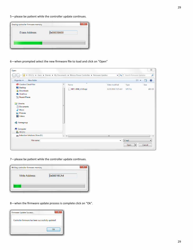
5—please be pa ent while the controller update con nues.
6—when prompted select the new firmware file to load and click on “Open”
8—when the firmware update process is complete click on “Ok”.
7—please be pa ent while the controller update con nues.
30
30
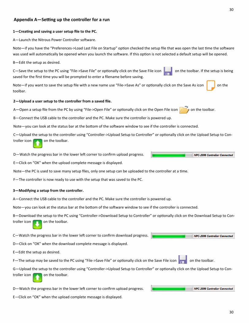
Appendix A—Se ng up the controller for a run
1—Crea ng and saving a user setup file to the PC.
A—Launch the Nitrous Power Controller so ware.
Note—if you have the “Preferences‐>Load Last File on Startup” op on checked the setup file that was open the last me the so ware
was used will automa cally be opened when you launch the so ware. If this op on is not selected a default setup will be opened.
B—Edit the setup as desired.
C—Save the setup to the PC using “File‐>Save File” or op onally click on the Save File icon on the toolbar. If the setup is being
saved for the first me you will be prompted to enter a filename before saving.
Note—if you want to save the setup file with a new name use “File‐>Save As” or op onally click on the Save As icon on the
toolbar.
3—Modifying a setup from the controller.
A—Connect the USB cable to the controller and the PC. Make sure the controller is powered up.
Note—you can look at the status bar at the bo om of the so ware window to see if the controller is connected.
B—Download the setup to the PC using “Controller‐>Download Setup to Controller” or op onally click on the Download Setup to Con‐
troller icon on the toolbar.
C—Watch the progress bar in the lower le corner to confirm download progress.
D—Click on “OK” when the download complete message is displayed.
E—Edit the setup as desired.
F—The setup may be saved to the PC using “File‐>Save File” or op onally click on the Save File icon on the toolbar.
G—Upload the setup to the controller using “Controller‐>Upload Setup to Controller” or op onally click on the Upload Setup to Con‐
troller icon on the toolbar.
D—Watch the progress bar in the lower le corner to confirm upload progress.
E—Click on “OK” when the upload complete message is displayed.
2—Upload a user setup to the controller from a saved file.
A—Open a setup file from the PC by using “File‐>Open File” or op onally click on the Open File icon on the toolbar.
B—Connect the USB cable to the controller and the PC. Make sure the controller is powered up.
Note—you can look at the status bar at the bo om of the so ware window to see if the controller is connected.
C—Upload the setup to the controller using “Controller‐>Upload Setup to Controller” or op onally click on the Upload Setup to Con‐
troller icon on the toolbar.
D—Watch the progress bar in the lower le corner to confirm upload progress.
E—Click on “OK” when the upload complete message is displayed.
Note—the PC is used to save many setup files, only one setup can be uploaded to the controller at a me.
F—The controller is now ready to use with the setup that was saved to the PC.

31
31
Appendix B—Typical procedure when making a run
A—Edit and upload a setup to the controller.
Important—it is the responsibility of the user to create a proper setup for their applica on!
B—Perform any usual pre‐race prepara ons, clean res, purge nitrous system, etc.
C—Make sure nitrous arming switch is on.
D—When the T‐Brake/Clutch Input is on the Ac va on Input will be ignored un l you release the trans brake or clutch.
Note—as long as the T‐Brake/Clutch Input is on you can go wide open for the launch without the progressive nitrous system star ng.
Important—if you are using the T‐Brake/Clutch Input Delay Timer the T‐Brake/Clutch Input will be ignored a er the ini al launch for
the amount of delay me set for this feature.
E—Stage the vehicle and launch.
F—The data log will begin recording once the data recording ac va on condi ons are met.
1—the default se ng for data recording ac va on is the Ac va on Input only.
2—you may configure the controller to only begin recording when the Ac va on Input and the T‐Brake/Clutch are both on.
3—you may also configure the controller to begin recording based on engine rpm.
Please see the “Data Setup” tab for these op ons.
G—A er the run you may turn the power off to the controller. The data log will be saved in the controller even with no power for sev‐
eral years.
Note—if you start another run before downloading the data log it will be over wri en!
H—See “Appendix C—Retrieving data log a er a run” for more informa on.

32
32
Appendix C—Retrieving data log a er a run
1—Download data log a er a run.
A—Launch the Nitrous Power Controller so ware.
B—Connect the USB cable to the controller and the PC. Make sure the controller is powered up.
Note—you can look at the status bar at the bo om of the so ware window to see if the controller is connected.
C—Download the data log to the controller using “Controller‐>Download Data Log from Controller” or op onally click on the Down‐
load Data Log from Controller icon on the toolbar.
D—Watch the progress bar in the lower le corner to confirm upload progress.
E—When the download is complete a message box will inform you if the current setup in the controller was used when the data was
logged (same setup used for run). Click OK to con nue.
1—If the setup has changed from the me when the run data log was created it will not be saved with the data log to the PC.
2—If the setup was used when the run data was recorded it will be saved with the data log to the PC.
Note—the setup can be loaded from the data log at a later date. For example you return to a track and want the same setup that was
used on a previous run. See below for instruc ons to retrieve the setup from a data log file.
Important—always download the data log before making any changes to the setup if you wish to have the setup saved with the data
log.
F—The save data log window will now open and prompt you to save with the automa cally generated file name or you may alter the
filename before saving.
G—A er saving the data log to a PC file the data graph will open and you can view the run data.
H—Click on the “Data Graph Help” bu on for help with the data graph func ons.
2—Retrieving setup from data log file saved to PC.
A—Launch the Nitrous Power Controller so ware.
B—Open a data log file from the PC by using “Data‐>Open Data Log File” or op onally click on the Open Data Log File icon on
the toolbar.
C—Click on the “Load Setup from Data Log” bu on.
1—If a valid setup was saved with the data log it will be loaded and you can view, edit, save, and/or upload to the controller.
2—If the setup was not saved with the data log you will not be able to retrieve it and a message box will appear indica ng
this.