np900-b16c a07800843 1 - dfi-itox · np900-b16c com express board user’s manual 935-np9001-000g...
TRANSCRIPT

NP900-B16CCOM Express Board
User’s Manual
935-NP9001-000GI07810911
Copyright
This publication contains information that is protected by copyright.No part of it may be reproduced in any form or by any means orused to make any transformation/adaptation without the prior writ-ten permission from the copyright holders.
This publication is provided for informational purposes only. Themanufacturer makes no representations or warranties with respect tothe contents or use of this manual and specifically disclaims any ex-press or implied warranties of merchantability or fitness for any par-ticular purpose. The user will assume the entire risk of the use or theresults of the use of this document. Further, the manufacturer re-serves the right to revise this publication and make changes to itscontents at any time, without obligation to notify any person or en-tity of such revisions or changes.
© 2009. All Rights Reserved.
Trademarks
Windows® 2000, Windows® CE, Windows® XP and Windows® XPEmbedded are registered trademarks of Microsoft Corporation.Product names or trademarks appearing in this manual are for iden-tification purpose only and are the properties of the respective own-ers.

FCC and DOC Statement on Class B
This equipment has been tested and found to comply with the limitsfor a Class B digital device, pursuant to Part 15 of the FCC rules.These limits are designed to provide reasonable protection againstharmful interference when the equipment is operated in a residentialinstallation. This equipment generates, uses and can radiate radio fre-quency energy and, if not installed and used in accordance with theinstruction manual, may cause harmful interference to radio communi-cations. However, there is no guarantee that interference will notoccur in a particular installation. If this equipment does cause harmfulinterference to radio or television reception, which can be determinedby turning the equipment off and on, the user is encouraged to tryto correct the interference by one or more of the following meas-ures:
• Reorient or relocate the receiving antenna.• Increase the separation between the equipment and the receiver.• Connect the equipment into an outlet on a circuit different from
that to which the receiver is connected.• Consult the dealer or an experienced radio TV technician for
help.
Notice:
1. The changes or modifications not expressly approved by theparty responsible for compliance could void the user's authorityto operate the equipment.
2. Shielded interface cables must be used in order to comply withthe emission limits.

Table of Contents
About this Manual................................................................................Warranty.................................................................................................Static Electricity Precaution................................................................Safety Measures.....................................................................................About the Package...............................................................................
Chapter 1 - Introduction....................................................................Specifications...................................................................................................................................Features..............................................................................................................................................
Chapter 2 - Hardware Installation....................................................System Board Layout ..........................................................................................................Mechanical Diagram................................................................................................................System Memory..........................................................................................................................Jumper Settings............................................................................................................................Connectors......................................................................................................................................LEDs......................................................................................................................................................SPI Flash ROM Socket.........................................................................................................Cooling Options.........................................................................................................................Installing NP900-B16C onto a Carrier Board..............................................
Chapter 3 - BIOS Setup......................................................................Award BIOS Setup Utility.................................................................................................Updating the BIOS..................................................................................................................
Chapter 4 - Supported Softwares.....................................................Drivers for Windows Vista System..........................................................................Drivers for Windows XP System..............................................................................
Appendix A - Watchdog Timer.............................................................
55667
88
10
11111213161722242531
363673
757698
118

Warranty
1. Warranty does not cover damages or failures that arised frommisuse of the product, inability to use the product, unauthorizedreplacement or alteration of components and product specifica-tions.
2. The warranty is void if the product has been subjected to physi-cal abuse, improper installation, modification, accidents or unau-thorized repair of the product.
3. Unless otherwise instructed in this user’s manual, the user maynot, under any circumstances, attempt to perform service, adjust-ments or repairs on the product, whether in or out of warranty.It must be returned to the purchase point, factory or authorizedservice agency for all such work.
4. We will not be liable for any indirect, special, incidental orconsequencial damages to the product that has been modifiedor altered.

1
6
Introduction
Static Electricity Precautions
It is quite easy to inadvertently damage your PC, system board,components or devices even before installing them in your systemunit. Static electrical discharge can damage computer componentswithout causing any signs of physical damage. You must take extracare in handling them to ensure against electrostatic build-up.
1. To prevent electrostatic build-up, leave the board in its anti-staticbag until you are ready to install it.
2. Wear an antistatic wrist strap.3. Do all preparation work on a static-free surface.4. Hold the device only by its edges. Be careful not to touch any of
the components, contacts or connections.5. Avoid touching the pins or contacts on all modules and connec-
tors. Hold modules or connectors by their ends.
Important:Electrostatic discharge (ESD) can damage your processor,disk drive and other components. Perform the upgrade in-struction procedures described at an ESD workstationonly. If such a station is not available, you can providesome ESD protection by wearing an antistatic wrist strapand attaching it to a metal part of the system chassis. If awrist strap is unavailable, establish and maintain contactwith the system chassis throughout any procedures requir-ing ESD protection.
Safety Measures
To avoid damage to the system:• Use the correct AC input voltage range.....
To reduce the risk of electric shock:• Unplug the power cord before removing the system chassis
cover for installation or servicing. After installation or servicing,cover the system chassis before plugging the power cord.
1
7
Introduction
About the Package
The package contains the following items. If any of these items aremissing or damaged, please contact your dealer or sales representa-tive for assistance.
The system boardOne heat sinkOne “Main Board Utility” CDOne QR (Quick Reference)
The board and accessories in the package may not come similar tothe information listed above. This may differ in accordance to thesales region or models in which it was sold. For more informationabout the standard package in your region, please contact yourdealer or sales representative.

1
8
Introduction
Processor
Chipset
System Memory
BIOS
Graphics
DMI
LAN
Audio
ExpansionInterfaces
• Intel® AtomTM N270 (Diamondville SC) processor• 1.6GHz core frequency, 1.10V voltage• 2.5W thermal design power• 512KB on-die second level cache• 533-MT/s FSB• 22x22 mm, 1.0 mm ball pitch and 437 balls FCBGA
• Intel® chipset- Intel® 945GSE Graphics Memory Controller Hub (GMCH)- Intel® 82801GBM I/O Controller Hub (ICH7M)
• One 200-pin SODIMM socket (1.8V)• Maximum memory supports up to 2GB• Supports 400MHz and 533MHz DDR2 SDRAM
• SPI interface BIOS (8Mbit)
• 133/166MHz internal graphics core render frequency at 1.05Vcore voltage
• One SDVO port (Port B)- SDVO slot reversal not supported
• Supports 18-bit dual-channel LVDS• Supports CRT resolutions up to SXGA+
• DMI lane width - x2 only• DMI lane reversal not supported
• One Realtek RTL8111C PCI Express Gigabit controller• Supports 10Mbps, 100Mbps and 1Gbps data transmission• IEEE 802.3 (10/100Mbps) and IEEE 802.3ab (1Gbps) compliant
• Supports Azalia AC97 interface
• PCI 2.3 interface (supports 4 PCI bus masters)• Supports 8 USB ports (USB 1.1/2.0 host controllers)• Supports 3 PCIE x1 interface• Suppor ts ADD2 interface. PCIE x16 VGA interface is not
supported.
Chapter 1 - Introduction
Specifications

1
9
Introduction
Serial ATA
IDE
Temperature
Humidity
Power
Regulatory
PCB
• SATA interface suppor ts data transfer rate up to 1.5Gb/s(150MB/s) per port
• Two SATA ports with independent DMA operation supportedon ports 0 and 2
• Two-mode operation supports legacy mode using I/O space oran AHCI mode using memory space
• SATA and PATA can be used in a combined function mode(When SATA is used with PATA, AHCI mode is not supported.)
• Bus Master IDE (PATA) controller• Supports up to two IDE devices• Ultra ATA 100/66/33
• Operating: 0oC to 60oC
• Operating: 10% to 90%
• Input: 12V, 5VSB, VCC_RTC
• EMC: CE, FCC Part 15 Class B
• Dimensions- COM Express basic form factor- 9.5cm (3.74") x 12.5cm (4.9")
• Compliance- PICMG COM Express R1.0 basic form factor, Type 2

1
10
Introduction
The Watchdog Timer function allows yourapplication to regularly “clear” the system at
the set time interval. If the system hangs or fails to function, it willreset at the set time interval so that your system will continue tooperate.
DDR2 is a higher performance DDR technologywhose data transfer rate delivers bandwidth of 4.3
GB per second and beyond. That is twice the speed of the conven-tional DDR without increasing its power consumption. DDR2SDRAM modules work at 1.8V supply compared to 2.6V memoryvoltage for DDR modules. DDR2 also incorporates new innovationssuch as the On-Die Termination (ODT) as well as larger 4-bit pre-fetch against DDR which fetches 2 bits per clock cycle.
The integrated graphics delivers exceptional 3Dgraphics performance.
The Realtek RTL8111C PCI Express Gigabitcontroller suppor ts up to 1Gbps data
transmission.
watchdog timer
graphics
Features
DDR2
gigabit lan
11
2Hardware Installation
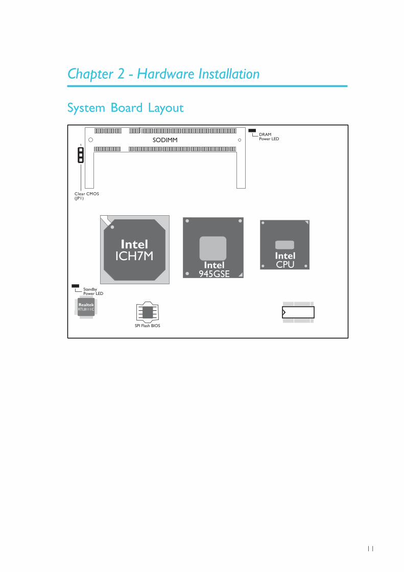
Chapter 2 - Hardware Installation
System Board Layout
SODIMM1
Clear CMOS(JP1)
IntelICH7M
Intel945GSE
IntelCPU
RealtekRTL8111C
StandbyPower LED
DRAMPower LED
SPI Flash BIOS

12
2Hardware Installation
Mechanical Diagram
A
B
C
D
E
F
G
H
J
K
L
M
N
P
R
T
U
V
W
Y
AA
12
34
58
9
10
11
12
13
14
15
16
17
18
19
20
21
67
27
28
1 2 3 4 5 6 7 8 9 10
11
12
13
14
15
16
17
18
19
20
21
22
23
24
25
26
A
B
C
D
E
F
G
H
J
K
L
M
N
P
R
T
U
V
W
Y
AA
AB
AC
AD
AE
AF
AG
AH
33 31
3032
2729
28
2325
26 24
21
2022
1719
18
15
1416
1113
12
9
810
57
6
1
2
3
4
A
B
C
D
E
F
G
H
J
K
L
M
N
P
R
T
U
V
W
Y
AA
AB
AC
AD
AE
AF
AG
AH
AJ
AK
AL
AM
AN
NP900
0.0
0
0.00
2.00
14.00
4.00
4.0
0
12
.50
70
.20
76
.00
11
7.0
0
12
1.0
0
4.00
0.00
87.00
12
1.0
0
91.00
11
7.0
0
87.00
0.0
0
91.00
4.0
0

13
2Hardware Installation
SODIMM
BIOS Setting
Configure the system memory in the Advanced Chipset Featuressubmenu of the BIOS.
System Memory

14
2Hardware Installation
Installing SODIMM
Note:The board used in the following illustrations may not resemblethe actual board. These illustrations are for reference only.
1. Make sure the PC and all other peripheral devices connected toit has been powered down.
2. Disconnect all power cords and cables.
3. Locate the SODIMM socket on the board.
4. Note the key on the socket. The keying mechanism ensures themodule can be plugged into the socket in only one way.
5. Grasping the module by its edges, insert the module into thesocket at an approximately 30 degrees angle. Note that thesocket and module are both keyed, which means the module canbe plugged into the socket in only one direction.

15
2Hardware Installation
6. To seat the module into the socket, apply firm even pressure toeach end of the module until it slips down into the socket. Thecontact fingers on the edge of the module will almost completelydisappear inside the socket.
7. Push down the module until the clips at each side of the socketlock into position. You will hear a distinctive “click”, indicating themodule is correctly locked into position.
ClipClip
8. To remove the module, simultaneously push the retaining clipsoutward to unlock the module.
16
2Hardware Installation
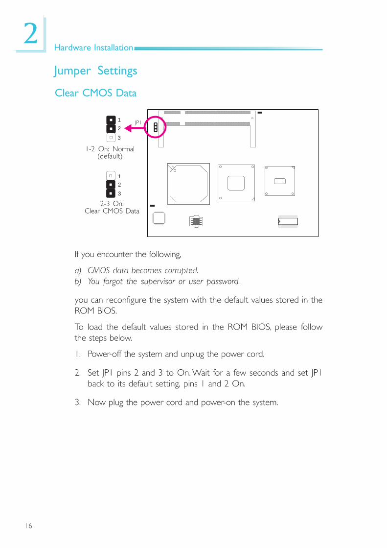
Jumper Settings
If you encounter the following,
a) CMOS data becomes corrupted.b) You forgot the supervisor or user password.
you can reconfigure the system with the default values stored in theROM BIOS.
To load the default values stored in the ROM BIOS, please followthe steps below.
1. Power-off the system and unplug the power cord.
2. Set JP1 pins 2 and 3 to On. Wait for a few seconds and set JP1back to its default setting, pins 1 and 2 On.
3. Now plug the power cord and power-on the system.
1-2 On: Normal(default)
JP1
2-3 On:Clear CMOS Data
Clear CMOS Data
3
12
3
12

17
2Hardware Installation
Connectors
COM Express Connectors
The COM Express connectors are used to interface the NP900-B16C COM Express board to a carrier board.
Connect the COM Express connectors, lcoated on the solder side ofthe board, to the COM Express connectors on the carrier board.Refer to the “Installing NP900-B16C onto a Carrier Board” sectionfor more information.
COM Expressconnectors
Refer to the following pages for the pin functions of these connec-tors.

18
2Hardware Installation
1 GND 56 PCIE_TX5-
2 GBE0_MDI3- 57 GND
3 GBE0_MDI3+ 58 PCIE_TX4+
4 GBE0_LINK100# 59 PCIE_TX4-
5 GBE0_LINK1000# 60 GND
6 GBE0_MDI2- 61 PCIE_TX2+
7 GBE0_MDI2+ 62 PCIE_TX2-
8 GBE0_LINK# 63 GPIO13
9 GBE0_MDI1- 64 PCIE_TX1+
10 GBE0_MDI1+ 65 PCIE_TX1-
11 GND 66 GND
12 GBE0_MDI0- 67 GPIO14
13 GBE0_MDI0+ 68 PCIE_TX0+
14 GBE0_CTREF 69 PCIE_TX0-
15 SUS_S3# 70 GND
16 SATA0_TX+ 71 LVDS_A0+
17 SATA0_TX- 72 LVDS_A0-
18 SUS_S4# 73 LVDS_A1+
19 SATA0_RX+ 74 LVDS_A1-
20 SATA0_RX- 75 LVDS_A2+
21 GND 76 LVDS_A2-
22 SATA2_TX+ 77 LVDS_VDD_EN
23 SATA2_TX- 78 N. C.
24 SUS_S5# 79 N. C.
25 SATA2_RX+ 80 GND
26 SATA2_RX- 81 LVDS_A_CK+
27 BATLOW# 82 LVDS_A_CK-
28 ATA_ACT# 83 LVDS_I2C_CK
29 AC_SYNC 84 LVDS_I2C_DAT
30 AC_RST# 85 GPIO15
31 GND 86 KBD_RST#
32 AC_BITCLK 87 KBD_A20GATE
33 AC_SDOUT 88 PCIE0_CK_REF+
34 BIOS_DISABLE# 89 PCIE0_CK_REF-
35 THRMTRIP# 90 GND
36 USB6- 91 N. C.
37 USB6+ 92 N. C.
38 USB_6_7_OC# 93 GPIO6
39 USB4- 94 N. C.
40 USB4+ 95 N. C.
41 GND 96 GND
42 USB2- 97 VCC_12V
43 USB2+ 98 VCC_12V
44 USB_2_3_OC# 99 VCC_12V
45 USB0- 100 GND
46 USB0+ 101 VCC_12V
47 VCC_RTC 102 VCC_12V
48 EXCD0_PERST# 103 VCC_12V
49 EXCD0_CPPE# 104 VCC_12V
50 LPC_SERIRQ 105 VCC_12V
51 GND 106 VCC_12V
52 N. C. 107 VCC_12V
53 N. C. 108 VCC_12V
54 GPIO12 109 VCC_12V
55 PCIE_TX5+ 110 GND
Row A

19
2Hardware Installation
1 GND 56 PCIE_RX5-
2 GBE_ACT# 57 GPIO38
3 LPC_FRAME# 58 PCIE_RX4+
4 LPC_AD0 59 PCIE_RX4-
5 LPC_AD1 60 GND
6 LPC_AD2 61 PCIE_RX2+
7 LPC_AD3 62 PCIE_RX2-
8 LPC_DRQ0# 63 GPIO39
9 LPC_DRQ1# 64 PCIE_RX1+
10 LPC_CLK 65 PCIE_RX1-
11 GND 66 WAKE0#
12 PWRBTN# 67 ICH_IR
13 SMB_CK 68 PCIE_RX0+
14 SMB_DAT 69 PCIE_RX0-
15 SMB_ALERT# 70 GND
16 SATA1_TX+ 71 LVDS_B0+
17 SATA1_TX- 72 LVDS_B0-
18 SUS_STAT# 73 LVDS_B1+
19 SATA1_RX+ 74 LVDS_B1-
20 SATA1_RX- 75 LVDS_B2+
21 GND 76 LVDS_B2-
22 SATA3_TX+ 77 N. C.
23 SATA3_TX- 78 N. C.
24 PWR_OK 79 LVDS_BKLT_EN
25 SATA3_RX+ 80 GND
26 SATA3_RX- 81 LVDS_B_CK+
27 WDT 82 LVDS_B_CK-
28 AC_SDIN2 83 LVDS_BKLT_CTRL
29 AC_SDIN1 84 VCC_5V_SBY
30 AC_SDIN0 85 VCC_5V_SBY
31 GND 86 VCC_5V_SBY
32 SPKR 87 VCC_5V_SBY
33 SMLINK0 88 N. C.
34 SMLINK1 89 VGA_RED
35 THRM# 90 GND
36 USB7- 91 VGA_GRN
37 USB7+ 92 VGA_BLU
38 USB_4_5_OC# 93 VGA_HSYNC
39 USB5- 94 VGA_VSYNC
40 USB5+ 95 VGA_I2C_CK
41 GND 96 VGA_I2C_DAT
42 USB3- 97 N. C.
43 USB3+ 98 N. C.
44 USB_0_1_OC# 99 N. C.
45 USB1- 100 GND
46 USB1+ 101 VCC_12V
47 EXCD1_PERST# 102 VCC_12V
48 EXCD1_CPPE# 103 VCC_12V
49 SYS_RESET# 104 VCC_12V
50 CB_RESET# 105 VCC_12V
51 GND 106 VCC_12V
52 N. C. 107 VCC_12V
53 N. C. 108 VCC_12V
54 GPIO7 109 VCC_12V
55 PCIE_RX5+ 110 GND
Row B

20
2Hardware Installation
1 GND 56 SDVOB_INT
2 IDE_D7 57 N. C.
3 IDE_D6 58 SDVO_FLDSTALL+
4 IDE_D3 59 SDVO_FLDSTALL-
5 IDE_D15 60 GND
6 IDE_D8 61 N. C.
7 IDE_D9 62 N. C.
8 IDE_D2 63 N. C.
9 IDE_D13 64 N. C.
10 IDE_D1 65 N. C.
11 GND 66 N. C.
12 IDE_D14 67 N. C.
13 IDE_IORDY 68 N. C.
14 IDE_IOR# 69 N. C.
15 PCI_PME# 70 GND
16 PCI_GNT2# 71 N. C.
17 PCI_REQ2# 72 N. C.
18 PCI_GNT1# 73 SDVO_DATA
19 PCI_REQ1# 74 N. C.
20 PCI_GNT0# 75 N. C.
21 GND 76 GND
22 PCI_REQ0# 77 N. C.
23 PCI_RESET# 78 N. C.
24 PCI_AD0 79 N. C.
25 PCI_AD2 80 GND
26 PCI_AD4 81 N. C.
27 PCI_AD6 82 N. C.
28 PCI_AD8 83 N. C.
29 PCI_AD10 84 GND
30 PCI_AD12 85 N. C.
31 GND 86 N. C.
32 PCI_AD14 87 GND
33 PCI_C/BE1# 88 N. C.
34 PCI_PERR# 89 N. C.
35 PCI_LOCK# 90 GND
36 PCI_DEVSEL# 91 N. C.
37 PCI_IRDY# 92 N. C.
38 PCI_C/BE2# 93 GND
39 PCI_AD17 94 N. C.
40 PCI_AD19 95 N. C.
41 GND 96 GND
42 PCI_AD21 97 N. C.
43 PCI_AD23 98 N. C.
44 PCI_C/BE3# 99 N. C.
45 PCI_AD25 100 GND
46 PCI_AD27 101 N. C.
47 PCI_AD29 102 N. C.
48 PCI_AD31 103 GND
49 PCI_IRQA# 104 VCC_12V
50 PCI_IRQB# 105 VCC_12V
51 GND 106 VCC_12V
52 SDVO_TVCLKIN+ 107 VCC_12V
53 SDVO_TVCLKIN- 108 VCC_12V
54 N. C. 109 VCC_12V
55 SDVOB_INT+ 110 GND
Row C

21
2Hardware Installation
1 GND 56 SDVOB_GRN-
2 IDE_D5 57 N. C.
3 IDE_D10 58 SDVOB_BLU+
4 IDE_D11 59 SDVOB_BLU-
5 IDE_D12 60 GND
6 IDE_D4 61 SDVOB_CK+
7 IDE_D0 62 SDVOB_CK-
8 IDE_REQ 63 N. C.
9 IDE_IOW# 64 N. C.
10 IDE_ACK# 65 N. C.
11 GND 66 N. C.
12 IDE_IRQ 67 GND
13 IDE_A0 68 N. C.
14 IDE_A1 69 N. C.
15 IDE_A2 70 GND
16 IDE_CS1 71 N. C.
17 IDE_CS3 72 N. C.
18 IDE_RESET# 73 SDVO_CLK
19 PCI_GNT3# 74 N. C.
20 PCI_REQ3# 75 N. C.
21 GND 76 GND
22 PCI_AD1 77 IDE_CBLID#
23 PCI_AD3 78 N. C.
24 PCI_AD5 79 N. C.
25 PCI_AD7 80 GND
26 PCI_C/BE0# 81 N. C.
27 PCI_AD9 82 N. C.
28 PCI_AD11 83 N. C.
29 PCI_AD13 84 GND
30 PCI_AD15 85 N. C.
31 GND 86 N. C.
32 PCI_PAR 87 GND
33 PCI_SERR# 88 N. C.
34 PCI_STOP# 89 N. C.
35 PCI_TRDY# 90 GND
36 PCI_FRAME# 91 N. C.
37 PCI_AD16 92 N. C.
38 PCI_AD18 93 GND
39 PCI_AD20 94 N. C.
40 PCI_AD22 95 N. C.
41 GND 96 GND
42 PCI_AD24 97 N. C.
43 PCI_AD26 98 N. C.
44 PCI_AD28 99 N. C.
45 PCI_AD30 100 GND
46 PCI_IRQC# 101 N. C.
47 PCI_IRQD# 102 N. C.
48 PCI_CLKRUN# 103 GND
49 N. C. 104 VCC_12V
50 PCI_CLK 105 VCC_12V
51 GND 106 VCC_12V
52 SDVOB_RED+ 107 VCC_12V
53 SDVOB_RED- 108 VCC_12V
54 N. C. 109 VCC_12V
55 SDVOB_GRN+ 110 GND
Row D
22
2Hardware Installation
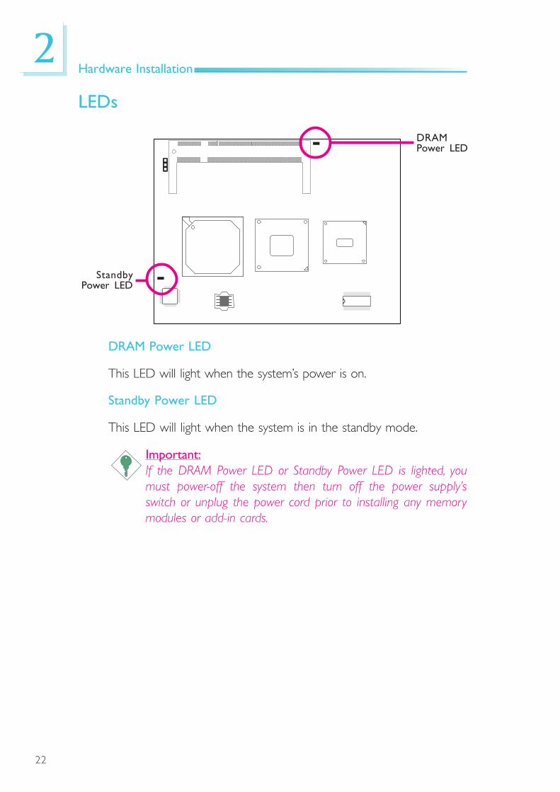
LEDs
DRAM Power LED
This LED will light when the system’s power is on.
Standby Power LED
This LED will light when the system is in the standby mode.
Important:If the DRAM Power LED or Standby Power LED is lighted, youmust power-off the system then turn off the power supply’sswitch or unplug the power cord prior to installing any memorymodules or add-in cards.
StandbyPower LED
DRAMPower LED

23
2Hardware Installation
SPI Flash ROM Socket
1. The photo on the rightshows the location ofthe SPI f lash ROMsocket.
2. If you need to replacethe ROM, open the leftcover first then the rightcover of the socket.
Open left cover
Open right cover
24
2Hardware Installation
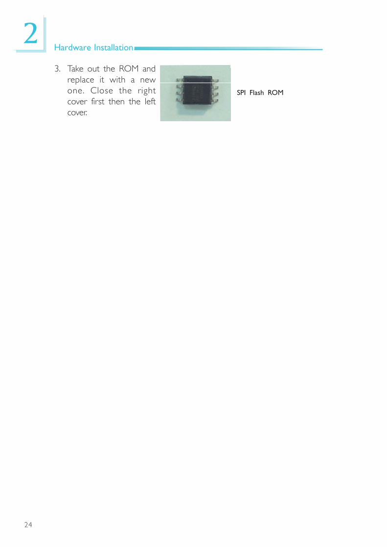
3. Take out the ROM andreplace it with a newone. Close the rightcover first then the leftcover.
SPI Flash ROM
25
2Hardware Installation
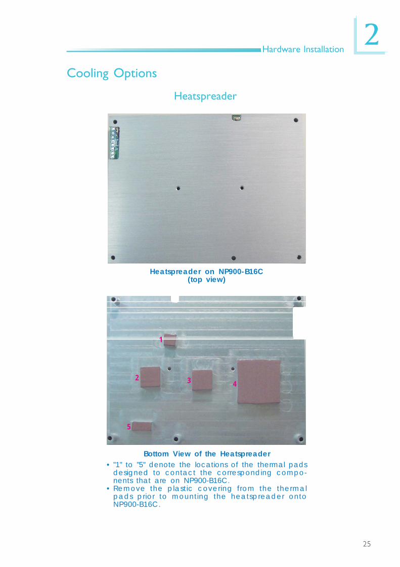
Heatspreader on NP900-B16C(top view)
Heatspreader
Bottom View of the Heatspreader• "1" to "5" denote the locations of the thermal pads
designed to contact the corresponding compo-nents that are on NP900-B16C.
• Remove the plastic covering from the thermalpads prior to mounting the heatspreader ontoNP900-B16C.
Cooling Options
3 4
5
1
2

26
2Hardware Installation
Dimensions
Top View
8.0
0
5- 5.00Ø
5.2
2
0.0
5
5.0
9
0.0
5
5.7
4
0.0
5
6.5
0
0.0
5
B C DA
3.0
0
5.1
2
0.0
5
E
Side View
4.0
08
7.0
0
95
.00
76.00
4.00 117.00
125.00
5-Ø2.70
7.00
66
.50
21
.50
47
.50
2-M2.5
R1.50
45.50 40.00
79.80 5.70
4.5
0

27
2Hardware Installation
“A” to “E”• Denotes the locations of the thermal pads.
“F” to “J”• Denotes the locations of the mounting posts.
These mounting posts are used to mount theheatspreader and NP900-B16C assembly onto acarrier board.
• Use M2.5 screws with minimum length of 16 mm.
Bottom View
29.75
64.80
96.80
102.85
11
.60
41
.70
39
.10
40
.50
26.00
12.00
12
.0026
.00
12.00
14.00
5.1
0
A
B C
D
12
.00
63
.78
7.00
7.0
0
85.15
E
F G H
I J

28
2Hardware Installation
Heat Sink
Heat Sink on NP900-B16C(top view)
Bottom View of the Passive Heat Sink• "1" to "5" denote the locations of the thermal pads
designed to contact the corresponding compo-nents that are on NP900-B16C.
• Remove the plastic covering from the thermalpads prior to mounting the heat sink onto NP900-B16C.
3 4
5
1
2

29
2Hardware Installation
Dimensions4
.00
87
.00
95
.00
76.00
4.00 117.00
125.00
5-Ø2.707.00
66
.50
21
.50 R
1.5
0
79.80 5.70
4.5
0
Top View
6.5
02
.50
25
.00
5- 5.00Ø
3.7
2
0.0
5
3.5
9
0.0
5
4.2
4
0.0
5
5.0
0
0.0
5
B C DA
3.6
2
0.0
5
Side View

30
2Hardware Installation
29.75
64.80
96.80
102.85
11
.60
41
.70
39
.10
40
.50
26.00
12.00
12
.0026
.00
12.00
14.00
5.1
0
A
B C
D
12
.00
63
.78
7.00
7.0
0
85.15
E
F G H
I J
“A” to “E”• Denotes the locations of the thermal pads.
“F” to “J”• Denotes the locations of the mounting posts.
These mounting posts are used to mount theheat sink and NP900-B16C assembly onto a car-rier board.
• Use M2.5 screws with minimum length of 12 mm.
Bottom View

31
2Hardware Installation
Installing NP900-B16C onto a Carrier Board
1. The photo below shows the locations of the mounting holes.
2. Insert the provided mounting screws into the mounting holes - fromthe bottom through the top of the carrier board.
Mountinghole
Mounting Screws
32
2Hardware Installation
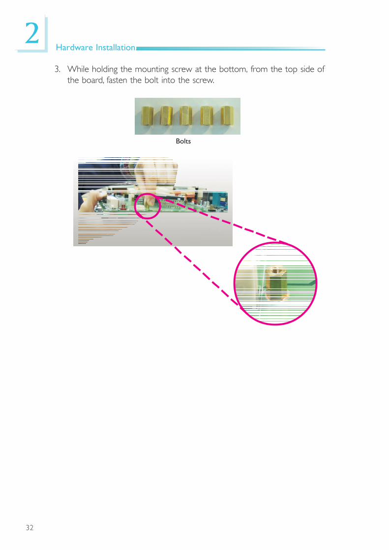
3. While holding the mounting screw at the bottom, from the top side ofthe board, fasten the bolt into the screw.
Bolts
33
2Hardware Installation
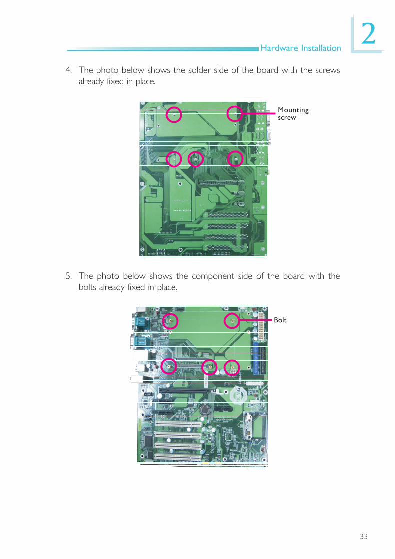
4. The photo below shows the solder side of the board with the screwsalready fixed in place.
Mountingscrew
5. The photo below shows the component side of the board with thebolts already fixed in place.
Bolt

34
2Hardware Installation
6. Grasping NP900-B16C by its edges, position it on top of the carrierboard with its mounting holes aligned with the bolts on the carrierboard. This will also align the COM Express connectors of the twoboards to each other.
Press NP900-B16C down firmly until it is completely seated on theCOM Express connectors of the carrier board.
COM Express Connectors onthe Solder Side of theNP900-B16C Board
COM Express Connectors onthe Carrier Board
NP900-B16C Installedon the Carrier Board

35
2Hardware Installation
7. Position the heat sink on top of NP900-B16C with the heat sink’smounting holes aligned with the mounting holes of NP900-B16C.
Use the provided long screws to secure the heat sink to the board.
Mounting Screws
Heat sink
8. The photo below shows a properly installed heat sink.
36
3BIOS Setup
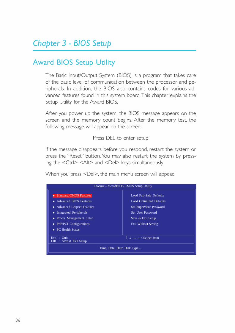
The Basic Input/Output System (BIOS) is a program that takes careof the basic level of communication between the processor and pe-ripherals. In addition, the BIOS also contains codes for various ad-vanced features found in this system board. This chapter explains theSetup Utility for the Award BIOS.
After you power up the system, the BIOS message appears on thescreen and the memory count begins. After the memory test, thefollowing message will appear on the screen:
Press DEL to enter setup
If the message disappears before you respond, restart the system orpress the “Reset” button. You may also restart the system by press-ing the <Ctrl> <Alt> and <Del> keys simultaneously.
When you press <Del>, the main menu screen will appear.
Phoenix - AwardBIOS CMOS Setup Utility
Load Fail-Safe Defaults
Load Optimized Defaults
Set Supervisor Password
Set User Password
Save & Exit Setup
Exit Without Saving
Esc : QuitF10 : Save & Exit Setup
↑ ↓ → ← : Select Item
Time, Date, Hard Disk Type...
Standard CMOS Features
Advanced BIOS Features
Advanced Chipset Features
Integrated Peripherals
Power Management Setup
PnP/PCI Configurations
PC Health Status
Chapter 3 - BIOS Setup
Award BIOS Setup Utility

37
3BIOS Setup
Date
The date format is <day>, <month>, <date>, <year>. Day displaysa day, from Sunday to Saturday. Month displays the month, fromJanuary to December. Date displays the date, from 1 to 31. Yeardisplays the year, from 1999 to 2099.
Time
The time format is <hour>, <minute>, <second>. The time is basedon the 24-hour military-time clock. For example, 1 p.m. is 13:00:00.Hour displays hours from 00 to 23. Minute displays minutes from00 to 59. Second displays seconds from 00 to 59.
The settings on the screen are for reference only. Your version may not beidentical to this one.
Standard CMOS Features
Use the arrow keys to highlight “Standard CMOS Features” andpress <Enter>. A screen similar to the one below will appear.
Date <mm:dd:yy>Time <hh:mm:ss>
IDE Channel 0 MasterIDE Channel 0 SlaveIDE Channel 1 MasterIDE Channel 1 Slave
Drive A
VideoHalt On
Base MemoryExtended MemoryTotal Memory
Phoenix - AwardBIOS CMOS Setup UtilityStandard CMOS Features
Item Help
Menu Level
Change the day, month,year and century
Mon, Nov 24 20089 : 3 : 54
NoneNoneNoneNone
1.44M, 3.5 in.
EGA/VGAAll Errors
640K1038336K1039360K
↑↓→←: Move Enter: Select F1: General Help+/-/PU/PD: Value F10: Save ESC: ExitF5: Previous Values F6: Fail-Safe Defaults F7: Optimized Defaults

38
3BIOS Setup
IDE HDD Auto Detection
Detects the parameters of the drive. The parameters will automati-cally be shown on the screen.
IDE Channel 0 Master and IDE Channel 0 Slave
If you select ”Auto”, the BIOS will auto-detect the HDD & CD-ROM drive at the POST stage and show the IDE for the HDD &CD-ROM drive. If a hard disk has not been installed, select “None”.
Access Mode
For hard drives larger than 528MB, you would typically select theLBA type. Certain operating systems require that you select CHS orLarge. Please check your operating system’s manual or Help desk onwhich one to select.
The settings on the screen are for reference only. Your version may not beidentical to this one.
IDE Channel 0 Master and IDE Channel 1 Slave
To configure the IDE drives, move the cursor to a field then press<Enter>. The following screen will appear.
IDE HDD Auto-Detection
IDE Channel 0 MasterAccess Mode
Capacity
CylinderHeadPrecompLanding ZoneSector
Phoenix - AwardBIOS CMOS Setup UtilityIDE Channel 0 Master
Item Help
Menu Level
To auto-detect theHDD’s size, head... onthis channel
↑↓→←: Move Enter: Select F1: General Help+/-/PU/PD: Value F10: Save ESC: ExitF5: Previous Values F6: Fail-Safe Defaults F7: Optimized Defaults
00000
Press Enter
AutoAuto
0MB

39
3BIOS Setup
Capacity
Displays the approximate capacity of the disk drive. Usually the sizeis slightly greater than the size of a formatted disk given by a diskchecking program.
Cylinder
This field displays the number of cylinders.
Head
This field displays the number of read/write heads.
Precomp
This field displays the number of cylinders at which to change thewrite timing.
Landing Zone
This field displays the number of cylinders specified as the landingzone for the read/write heads.
Sector
This field displays the number sectors per track.
Drive A
This field identifies the type of floppy disk drive installed.
None No floppy drive is installed360K, 5.25 in. 5-1/4 in. standard drive; 360KB capacity1.2M, 5.25 in. 5-1/4 in. AT-type high-density drive; 1.2MB capacity720K, 3.5 in. 3-1/2 in. double-sided drive; 720KB capacity1.44M, 3.5 in. 3-1/2 in. double-sided drive; 1.44MB capacity2.88M, 3.5 in. 3-1/2 in. double-sided drive; 2.88MB capacity

40
3BIOS Setup
Video
This field selects the type of video adapter used for the primarysystem monitor. Although secondary monitors are supported, you donot have to select the type. The default setting is EGA/VGA.
EGA/VGA Enhanced Graphics Adapter/Video Graphics Array. ForEGA, VGA, SVGA and PGA monitor adapters.
CGA 40 Color Graphics Adapter. Power up in 40-columnmode.
CGA 80 Color Graphics Adapter. Power up in 80-columnmode.
Mono Monochrome adapter. Includes high resolution mono-chrome adapters.
Halt On
This field determines whether the system will stop if an error isdetected during power up. The default setting is All Errors.
No Errors The system boot will not stop for any errors detected.All Errors The system boot will stop whenever the BIOS detects
a non-fatal error.All, But Keyboard The system boot will not stop for a keyboard
error ; it will stop for all other errors.All, But Diskette The system boot will not stop for a disk error ;
it will stop for all other errors.All, But Disk/Key The system boot will not stop for a disk or
keyboard error ; it will stop for all other errors.
Base Memory
Displays the amount of base (or conventional) memory installed inthe system. The value of the base memory is typically 512K forsystems with 512K memory installed on the motherboard or 640Kfor systems with 640K or more memory installed on themotherboard.

41
3BIOS Setup
Extended Memory
Displays the amount of extended memory detected during boot-up.
Total Memory
Displays the total memory available in the system.
42
3BIOS Setup
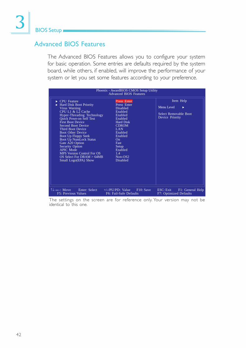
Advanced BIOS Features
The Advanced BIOS Features allows you to configure your systemfor basic operation. Some entries are defaults required by the systemboard, while others, if enabled, will improve the performance of yoursystem or let you set some features according to your preference.
CPU FeatureHard Disk Boot PriorityVirus WarningCPU L1 & L2 CacheHyper-Threading TechnologyQuick Powe-on Self TestFirst Boot DeviceSecond Boot DeviceThird Boot DeviceBoot Other DeviceBoot Up Floppy SeekBoot Up NumLock StatusGate A20 OptionSecurity OptionAPIC ModeMPS Version Control For OSOS Select For DRAM > 64MBSmall Logo(EPA) Show
Phoenix - AwardBIOS CMOS Setup UtilityAdvanced BIOS Features
Item Help
Menu Level
Select Removable BootDevice Priority
↑↓→←: Move Enter: Select F1: General Help+/-/PU/PD: Value F10: Save ESC: ExitF5: Previous Values F6: Fail-Safe Defaults F7: Optimized Defaults
Press EnterPress EnterDisabledEnabledEnabledEnabledHard DiskCDROMLANEnabledEnabledOnFastSetupEnabled1.4Non-OS2Disabled
The settings on the screen are for reference only. Your version may not beidentical to this one.
43
3BIOS Setup
The settings on the screen are for reference only. Your version may not beidentical to this one.
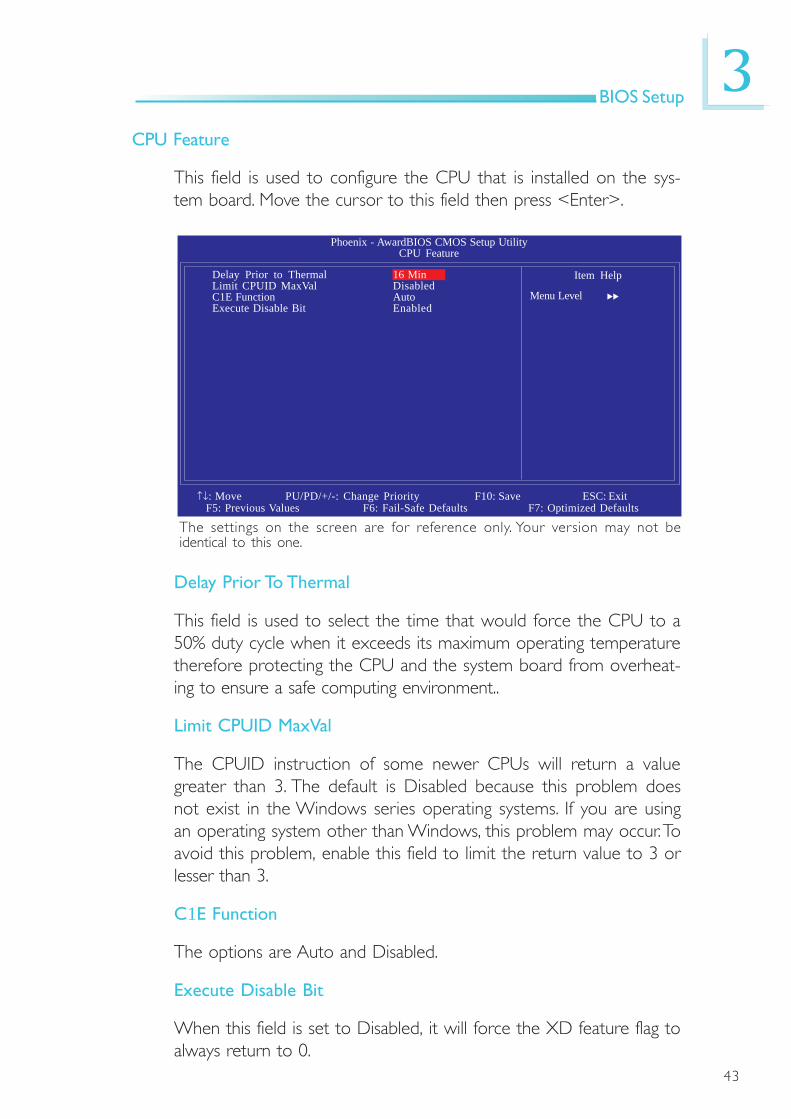
Phoenix - AwardBIOS CMOS Setup UtilityCPU Feature
Item Help
Menu Level
↑↓: Move PU/PD/+/-: Change Priority F10: Save ESC: ExitF5: Previous Values F6: Fail-Safe Defaults F7: Optimized Defaults
Delay Prior to ThermalLimit CPUID MaxValC1E FunctionExecute Disable Bit
16 MinDisabledAutoEnabled
Delay Prior To Thermal
This field is used to select the time that would force the CPU to a50% duty cycle when it exceeds its maximum operating temperaturetherefore protecting the CPU and the system board from overheat-ing to ensure a safe computing environment..
Limit CPUID MaxVal
The CPUID instruction of some newer CPUs will return a valuegreater than 3. The default is Disabled because this problem doesnot exist in the Windows series operating systems. If you are usingan operating system other than Windows, this problem may occur. Toavoid this problem, enable this field to limit the return value to 3 orlesser than 3.
C1E Function
The options are Auto and Disabled.
Execute Disable Bit
When this field is set to Disabled, it will force the XD feature flag toalways return to 0.
CPU Feature
This field is used to configure the CPU that is installed on the sys-tem board. Move the cursor to this field then press <Enter>.
44
3BIOS Setup
Virus Warning
This field protects the boot sector and partition table of your harddisk drive. When this field is enabled, the Award BIOS will monitorthe boot sector and partition table of the hard disk drive. If anattempt is made to write to the boot sector or partition table ofthe hard disk drive, the BIOS will halt the system and an errormessage will appear.
After seeing the error message, if necessary, you will be able to runan anti-virus program to locate and remove the problem before anydamage is done. Many disk diagnostic programs which attempt toaccess the boot sector table will cause the warning message toappear. If you are running such a program, we recommend that youfirst disable this field.
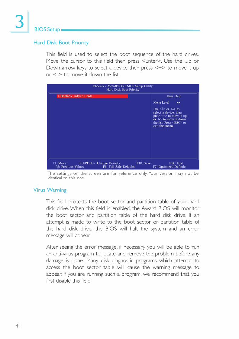
Hard Disk Boot Priority
This field is used to select the boot sequence of the hard drives.Move the cursor to this field then press <Enter>. Use the Up orDown arrow keys to select a device then press <+> to move it upor <-> to move it down the list.
The settings on the screen are for reference only. Your version may not beidentical to this one.
Phoenix - AwardBIOS CMOS Setup UtilityHard Disk Boot Priority
Item Help
Menu Level
Use <↑> or <↓> toselect a device, thenpress <+> to move it up,or <-> to move it downthe list. Press <ESC> toexit this menu.
↑↓: Move PU/PD/+/-: Change Priority F10: Save ESC: ExitF5: Previous Values F6: Fail-Safe Defaults F7: Optimized Defaults
1. Bootable Add-in Cards

45
3BIOS Setup
CPU L1 and L2 Cache
This field is used to speed up the memory access. Enable the exter-nal cache for better performance.
Hyper-Threading Technology
This field is used to enable the functionality of an Intel® processorthat supports Hyper-Threading Technology and will appear only whenusing this processor.
Quick Power On Self Test
This field speeds up Power On Self Test (POST) after you power onthe system. When Enabled, the BIOS will shorten or skip some checkitems during POST.
First Boot Device, Second Boot Device, Third Boot Device and BootOther Device
Select the drive to boot first, second and third in the “First BootDevice” “Second Boot Device” and “Third Boot Device” fields re-spectively. The BIOS will boot the operating system according to thesequence of the drive selected. Set “Boot Other Device” to Enabledif you wish to boot from another device.
Boot Up Floppy Seek
When enabled, the BIOS will check whether the floppy disk drive in-stalled is 40 or 80 tracks. Note that the BIOS cannot distinguish be-tween 720K, 1.2M, 1.44M and 2.88M drive types as they are all 80tracks. When disabled, the BIOS will not search for the type of floppydisk drive by track number. Note that there will not be any warningmessage if the drive installed is 360KB.
Boot Up NumLock Status
This allows you to determine the default state of the numerickeypad. By default, the system boots up with NumLock on whereinthe function of the numeric keypad is the number keys. When set toOff, the function of the numeric keypad is the arrow keys.
46
3BIOS Setup
Gate A20 Option
This entry allows you to select how gate A20 is handled. Gate A20is a device used to address memory above 1 Mbyte. Initially, gate A20was handled via the keyboard controller. Today, while keyboards stillprovide this support, it is more common, and much faster, for the sys-tem chipset to provide support for gate A20.
Security Option
This field determines when the system will prompt for the password- everytime the system boots or only when you enter the BIOSsetup. Set the password in the Set Supervisor/User Passwordsubmenu.
System The system will not boot and access to Setup will bedenied unless the correct password is entered at theprompt.
Setup The system will boot, but access to Setup will be deniedunless the correct password is entered at the prompt.
APIC Mode
Leave this field in its default setting.
MPS Version Control for OS
This field is used to select the MPS version used by the system.
OS Select for DRAM > 64MB
This field allows you to access the memory that is over 64MB inOS/2. The options are: Non-OS2 and OS2.
Small Logo(EPA) Show
Enabled The EPA logo will appear during system boot-up.Disabled The EPA logo will not appear during system boot-up.
47
3BIOS Setup
Advanced Chipset Features
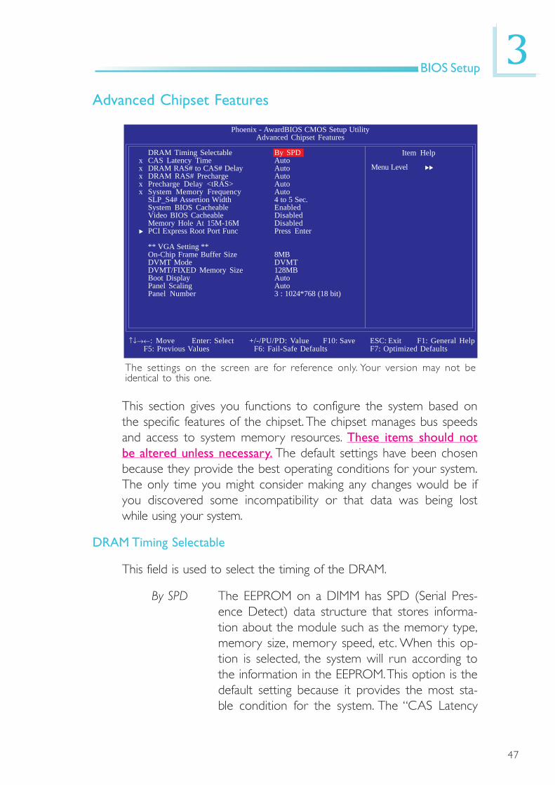
This section gives you functions to configure the system based onthe specific features of the chipset. The chipset manages bus speedsand access to system memory resources. These items should notbe altered unless necessary. The default settings have been chosenbecause they provide the best operating conditions for your system.The only time you might consider making any changes would be ifyou discovered some incompatibility or that data was being lostwhile using your system.
DRAM Timing Selectable
This field is used to select the timing of the DRAM.
By SPD The EEPROM on a DIMM has SPD (Serial Pres-ence Detect) data structure that stores informa-tion about the module such as the memory type,memory size, memory speed, etc. When this op-tion is selected, the system will run according tothe information in the EEPROM. This option is thedefault setting because it provides the most sta-ble condition for the system. The “CAS Latency
Phoenix - AwardBIOS CMOS Setup UtilityAdvanced Chipset Features
DRAM Timing Selectablex CAS Latency Timex DRAM RAS# to CAS# Delayx DRAM RAS# Prechargex Precharge Delay <tRAS>x System Memory Frequency
SLP_S4# Assertion WidthSystem BIOS CacheableVideo BIOS CacheableMemory Hole At 15M-16MPCI Express Root Port Func
** VGA Setting **On-Chip Frame Buffer SizeDVMT ModeDVMT/FIXED Memory SizeBoot DisplayPanel ScalingPanel Number
Item Help
Menu Level
By SPDAutoAutoAutoAutoAuto4 to 5 Sec.EnabledDisabledDisabledPress Enter
8MBDVMT128MBAutoAuto3 : 1024*768 (18 bit)
↑↓→←: Move Enter: Select F1: General Help+/-/PU/PD: Value F10: Save ESC: ExitF5: Previous Values F6: Fail-Safe Defaults F7: Optimized Defaults
The settings on the screen are for reference only. Your version may not beidentical to this one.

48
3BIOS Setup
Time” to “System Memory Frequency” fields willshow the default settings by SPD.
Manual If you want better performance for your systemother than the one “by SPD”, select “Manual” thenselect the best option in the “CAS Latency Time”to “System Memory Frequency” fields.
CAS Latency Time
This field is used to select the local memory clock periods.
DRAM RAS# to CAS# Delay
This field is used to select the latency between the DRAM activecommand and the read/write command.
DRAM RAS# Precharge
This field is used to select the idle clocks after issuing a prechargecommand to the DRAM.
Precharge Delay (tRAS)
The options are Auto and 4 to15.
System Memory Frequency
This field is used to select the frequency of the system memory.
SLP_S4# Assertion Width
The options are 1 to 2 Sec., 2 to 3 Sec., 3 to 4 Sec. and 4 to 5Sec.
System BIOS Cacheable
When this field is enabled, accesses to the system BIOS ROM ad-dressed at F0000H-FFFFFH are cached, provided that the cachecontroller is enabled. The larger the range of the Cache RAM, thehigher the efficiency of the system.
49
3BIOS Setup
Video BIOS Cacheable
As with caching the system BIOS, enabling the Video BIOS cache willallow access to video BIOS addresssed at C0000H to C7FFFH tobe cached, if the cache controller is also enabled. The larger the rangeof the Cache RAM, the faster the video performance.
Memory Hole At 15M-16M
In order to improve system performance, certain space in memory canbe reserved for ISA cards. This memory must be mapped into thememory space below 16MB. When enabled, the CPU assumes the 15-16MB memory range is allocated to the hidden ISA address rangeinstead of the actual system DRAM. When disabled, the CPU assumesthe 15-16MB address range actually contains DRAM memory. If morethan 16MB of system memory is installed, this field must be disabledto provide contiguous system memory.
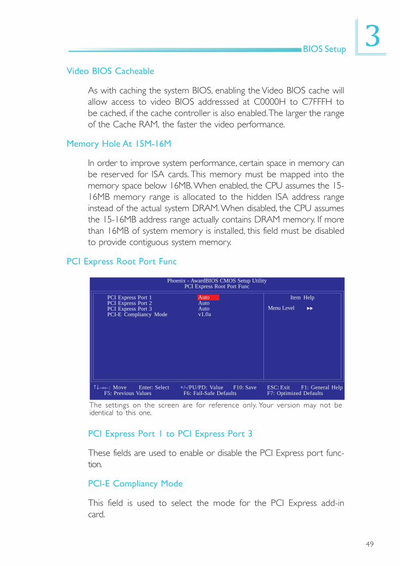
PCI Express Root Port Func
The settings on the screen are for reference only. Your version may not beidentical to this one.
Phoenix - AwardBIOS CMOS Setup UtilityPCI Express Root Port Func
PCI Express Port 1PCI Express Port 2PCI Express Port 3PCI-E Compliancy Mode
Item Help
Menu Level
AutoAutoAutov1.0a
↑↓→←: Move Enter: Select F1: General Help+/-/PU/PD: Value F10: Save ESC: ExitF5: Previous Values F6: Fail-Safe Defaults F7: Optimized Defaults
PCI Express Port 1 to PCI Express Port 3
These fields are used to enable or disable the PCI Express port func-tion.
PCI-E Compliancy Mode
This field is used to select the mode for the PCI Express add-incard.

50
3BIOS Setup
On-Chip Frame Buffer Size
This field is used to select the onboard VGA’s frame buffer size thatis shared from the system memory.
DVMT Mode
The options are DVMT, Fixed and Both.
DVMT/Fixed Memory Size
This field is used to select the graphics memory size used by DVMT/Fixed mode.
Boot Display
This field is used to select the type of display to use when thesystem boots.
CRT Select this option if you want the system to bootthe CRT display.
LFP Select this option if you want the system to bootthe LCD flat panel display.
CRT+LFP Select this option if you want the system to bootboth the CRT and LCD flat panel display.
EFP Select this option if you want the system to bootthe EFP display.
CRT+EFP Select this option if you want the system to bootboth the CRT and EFP display.
Panel Scaling
This options are Auto, On and Off.
Panel Number
This field is used to select the type of panel that you are using.

51
3BIOS Setup
Integrated Peripherals
The settings on the screen are for reference only. Your version may not beidentical to this one.
OnChip IDE Device
Move the cursor to this field and press <Enter>. The followingscreen will appear.
The settings on the screen are for reference only. Your version may not beidentical to this one.
Phoenix - AwardBIOS CMOS Setup UtilityIntegrated Peripherals
Item Help
Menu Level
↑↓→←: Move Enter: Select F1: General Help+/-/PU/PD: Value F10: Save ESC: ExitF5: Previous Values F6: Fail-Safe Defaults F7: Optimized Defaults
OnChip IDE DeviceOnboard DeviceSuper IO Device
Press EnterPress EnterPress Enter
IDE HDD Block ModeIDE DMA Transfer AccessOn-Chip Primary PCI IDEIDE Primary Master UDMAIDE Primary Slave UDMA
*** On-Chip Serial ATA Setting ***x SATA Mode
On-Chip Serial ATAx PATA IDE Mode
SATA Port
Phoenix - AwardBIOS CMOS Setup UtilityOnChip IDE Device
Item Help
Menu Level
↑↓→←: Move Enter: Select F1: General Help+/-/PU/PD: Value F10: Save ESC: ExitF5: Previous Values F6: Fail-Safe Defaults F7: Optimized Defaults
EnabledEnabledEnabledAutoAuto
IDEAutoSecondaryP0, P2 is Primary
If your IDE hard drivesupports block modeSelect Enabled forautomatic detection ofthe optimal number ofblock read/writes persector the drive cansupport

52
3BIOS Setup
IDE HDD Block Mode
Enabled The IDE HDD uses the block mode. The system BIOSwill check the hard disk drive for the maximum blocksize the system can transfer. The block size will dependon the type of hard disk drive.
Disabled The IDE HDD uses the standard mode.
IDE DMA Transfer Access
This field is used to enable or disable the DMA transfer function ofan IDE hard drive.
On-Chip Primary PCI IDE
This field allows you to enable or disable the primary and secondaryIDE controller. The default is Enabled. Select Disabled if you want toadd a different hard drive controller
IDE Primary Master/Slave UDMA
These fields allow you to set the Ultra DMA in use. When Auto isselected, the BIOS will select the best available option after checkingyour hard drive or CD-ROM
Auto The BIOS will automatically detect the settings foryou.
Disabled The BIOS will not detect these categories.
SATA Mode
IDE This option configures the Serial ATA drives asParallel ATA storage devices.
AHCI This option allows the Serial ATA devices to useAHCI (Advanced Host Controller Interface).

53
3BIOS Setup
On-Chip Serial ATA
Disabled Disables the onboard SATA.Auto The system will detect the existing SATA and
IDE drives then automatically set them to theavailable master/slave mode.
Combined Mode This option allows you to combine both IDEand SATA drives; supporting maximum of 2drives on each channel.
Enhanced Mode This option allows you to use both IDE andSATA drives; allowing a maximum of 4 drives -1 IDE Master, 1 IDE Slave and 2 SATA.
SATA Only This option automatically sets the SATA drivesto Primary Master mode. Since the SATAdrives are in Master mode, you cannot set theIDE drive to Master mode.
PATA IDE Mode and SATA Port
This field is used to select the function mode for the IDE connectorand its relation to the SATA ports.
Secondary IDE serves as Secondary Master and Second-ary Slave channel. SATA 1 and SATA 2 serveas Primary Master and Primary Slave channel.
54
3BIOS Setup
The settings on the screen are for reference only. Your version may not beidentical to this one.
Phoenix - AwardBIOS CMOS Setup UtilityOnboard Device
Item Help
Menu Level
↑↓→←: Move Enter: Select F1: General Help+/-/PU/PD: Value F10: Save ESC: ExitF5: Previous Values F6: Fail-Safe Defaults F7: Optimized Defaults
Onboard LAN ControlOnboard PXE ROM ControlAzalia/AC97 Audio SelectUSB Device Setting
EnabledDisabledAutoPress Enter
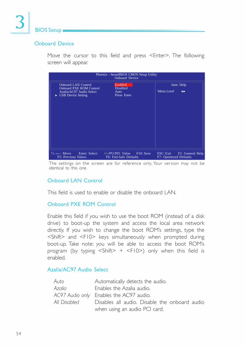
Onboard Device
Move the cursor to this field and press <Enter>. The followingscreen will appear.
Onboard LAN Control
This field is used to enable or disable the onboard LAN.
Onboard PXE ROM Control
Enable this field if you wish to use the boot ROM (instead of a diskdrive) to boot-up the system and access the local area networkdirectly. If you wish to change the boot ROM’s settings, type the<Shift> and <F10> keys simultaneously when prompted duringboot-up. Take note: you will be able to access the boot ROM’sprogram (by typing <Shift> + <F10>) only when this field isenabled.
Azalia/AC97 Audio Select
Auto Automatically detects the audio.Azalia Enables the Azalia audio.AC97 Audio only Enables the AC97 audio.All Disabled Disables all audio. Disable the onboard audio
when using an audio PCI card.

55
3BIOS Setup
USB Device Setting
Move the cursor to this field and press <Enter>. The followingscreen will appear.
The settings on the screen are for reference only. Your version may not beidentical to this one.
Phoenix - AwardBIOS CMOS Setup UtilityUSB Device Setting
Item Help
Menu Level
↑↓→←: Move Enter: Select F1: General Help+/-/PU/PD: Value F10: Save ESC: ExitF5: Previous Values F6: Fail-Safe Defaults F7: Optimized Defaults
USB 1.0 ControllerUSB 2.0 ControllerUSB Operation ModeUSB Keyboard FunctionUSB Mouse FunctionUSB Storage Function
*********USB Mass Storage Device Boot Setting*****
EnabledEnabledHigh SpeedEnabledEnabledEnabled
USB 1.0 Controller
This field is used to enable or disable the Universal Host ControllerInterface (USB 1.0).
USB 2.0 Controller
This field is used to enable or disable the Enhanced Host ControllerInterface (USB 2.0).
USB Operation Mode
This field is used to select the USB’s operation mode. The optionsare Full/Low Speed and High Speed.

56
3BIOS Setup
USB Keyboard Function
Due to the limited space of the BIOS ROM, the support for legacyUSB keyboard (in DOS mode) is by default set to Disabled. Withmore BIOS ROM space available, it will be able to support moreadvanced features as well as provide compatibility to a wide varietyof peripheral devices.
If a PS/2 keyboard is not available and you need to use a USBkeyboard to install Windows (installation is performed in DOSmode) or run any program under DOS, set this field to Enabled.
USB Mouse Function
Due to the limited space of the BIOS ROM, the support for legacyUSB mouse (in DOS mode) is by default set to Disabled. Withmore BIOS ROM space available, it will be able to support moreadvanced features as well as provide compatibility to a wide varietyof peripheral devices.
If a PS/2 mouse is not available and you need to use a USB mouseto install Windows (installation is performed in DOS mode) or runany program under DOS, set this field to Enabled.
USB Storage Function
This field is used to enable or disable the support for legacy USBmass storage.

57
3BIOS Setup
Power On Function
This field allows you to use the PS/2 keyboard or PS/2 mouse topower-on the system.
Keyboard 98 When this option is selected, press the “wake up”key of the Windows® 98 compatible keyboard topower-on the system.
Button only Default setting. Uses the power button to poweron the system.
Hot Key When this option is selected, select the functionkey you would like to use to power-on the systemin the “Hot Key Power On” field.
Mouse Left When this option is selected, double-click the leftbutton of the mouse to power-on the system.
Mouse Right When this option is selected, double-click the rightbutton of the mouse to power-on the system.
Any Key Press any key to power-on the system.
Super IO Device
Move the cursor to this field and press <Enter>. The followingscreen will appear.
The settings on the screen are for reference only. Your version may not beidentical to this one.
Phoenix - AwardBIOS CMOS Setup UtilitySuper IO Device
Item Help
Menu Level
↑↓→←: Move Enter: Select F1: General Help+/-/PU/PD: Value F10: Save ESC: ExitF5: Previous Values F6: Fail-Safe Defaults F7: Optimized Defaults
Power On Functionx Hot Key Power ON
Onboard FDC ControllerPWRON After PWR-FailOnboard Serial Port 1Serial Port 1 Use IRQSerial Port 1 ModeOnboard Serial Port 2Serial Port 2 Use IRQOnboard Serial Port 3Serial Port 3 Use IRQOnboard Serial Port 4Serial Port 4 Use IRQW83627HF/HG.WDT Time
BUTTON ONLYCtrl-F1EnabledOff3F8IRQ4Normal2F8IRQ33E8IRQ102E8IRQ110

58
3BIOS Setup
Hot Key Power On
This field is used to select a function key that you would like to useto power-on the system.
Onboard FDC Controller
Enabled Enables the onboard floppy disk controller.Disabled Disables the onboard floppy disk controller.
PWRON After PWR-Fail
Off When power returns after an AC power failure, thesystem’s power is off. You must press the Power buttonto power-on the system.
On When power returns after an AC power failure, thesystem will automatically power-on.
Former-Sts When power returns after an AC power failure, thesystem will return to the state where you left off beforepower failure occurs. If the system’s power is off whenAC power failure occurs, it will remain off when powerreturns. If the system’s power is on when AC powerfailure occurs, the system will power-on when powerreturns.
Onboard Serial Port 1, Onboard Serial Port 2, Onboard Serial Port3 and Onboard Serial Port 4
3F8, 2F8, 3E8, 2E8 Allows you to manually select an I/O address forthe serial port.
Disabled Disables the serial port.
Serial Port 1 Mode
COM 1 functions as a serial port or IrDA. You cannot use both atthe same time.
Normal This option sets COM 1 as serial port.IrDA This option sets COM 1 as IrDA.
59
3BIOS Setup
Serial Port 1 Use IRQ, Serial Port 2 Use IRQ, Serial Port 3 UseIRQ and Serial Port 4 Use IRQ
These fields are used to select an IRQ for the onboard serial port 1,2, 3 or 4.
W83627HF/HG.WDT Time
This field is used to select the time interval of the Watchdog timer. Ifthe system hangs or fails to function, it will reset at the set timeinterval so that your system will continue to operate.

60
3BIOS Setup
Power Management Setup
The Power Management Setup allows you to configure your systemto most effectively save energy.
The settings on the screen are for reference only. Your version may not beidentical to this one.
ACPI Function
This function should be enabled only in operating systems thatsupport ACPI.
ACPI Suspend Type
This field is used to select the type of Suspend mode.
S1(POS) Enables the Power On Suspend function.S3(STR) Enables the Suspend to RAM function.
Phoenix - AwardBIOS CMOS Setup UtilityPower Management Setup
Item Help
Menu Level
↑↓→←: Move Enter: Select F1: General Help+/-/PU/PD: Value F10: Save ESC: ExitF5: Previous Values F6: Fail-Safe Defaults F7: Optimized Defaults
ACPI FunctionACPI Suspend TypeSoft-Off By PWR-BTTNWake-Up by PCI CardWake-Up by RingUSB KB Wake-Up From S3Resume By Alarm
x Date(of Month) Alarmx Time (hh:mm:ss) Alarm
EnabledS3(STR)Instant-OffDisabledDisabledDisabledDisabled00 : 0 : 0

61
3BIOS Setup
Soft-Off by PWR-BTTN
This field allows you to select the method of powering off yoursystem.
Delay 4 Sec. Regardless of whether the Power Management func-tion is enabled or disabled, if the power button ispushed and released in less than 4 sec, the systementers the Suspend mode. The purpose of this func-tion is to prevent the system from powering off incase you accidentally “hit” or pushed the power but-ton. Push and release again in less than 4 sec torestore. Pushing the power button for more than 4seconds will power off the system.
Instant-Off Pressing and then releasing the power button atonce will immediately power off your system.
Wake-Up By PCI Card
Enabled This field should be set to Enabled only if your PCIcard such as LAN card or modem card uses the PCIPME (Power Management Event) signal to remotelywake up the system. Access to the LAN card or PCIcard will cause the system to wake up. Refer to thecard’s documentation for more information.
Disabled The system will not wake up despite access to the PCIcard.

62
3BIOS Setup
Wake-Up By Ring
When this field is set to Enabled, the system will power-on to respondto calls coming from a modem.
USB KB Wake-Up From S3
This field, when enabled, allows you to use a USB keyboard or USBmouse to wake up a system that is in the S3 (STR - Suspend ToRAM) state. This can be configured only if the “ACPI Suspend Type”field is set to “S3(STR)”.
Resume By Alarm
Enabled When Enabled, you can set the date and time youwould like the Soft Power Down (Soft-Off) PC topower-on in the “Date (of Month) Alarm” and “Time(hh:mm:ss) Alarm” fields. However, if the system is beingaccessed by incoming calls or the network (Resume OnRing/LAN) prior to the date and time set in thesefields, the system will give priority to the incoming callsor network.
Disabled Disables the automatic power-on function. (default)
Date (of Month) Alarm
0 The system will power-on everyday according to thetime set in the “Time (hh:mm:ss) Alarm” field.
1-31 Select a date you would like the system to power-on.The system will power-on on the set date, and time setin the “Time (hh:mm:ss) Alarm” field.

63
3BIOS Setup
Time (hh:mm:ss) Alarm
This is used to set the time you would like the system to power-on.If you want the system to power-on everyday as set in the “Date(of Month) Alarm” field, the time set in this field must be later thanthe time of the RTC set in the Standard CMOS Features submenu.
64
3BIOS Setup
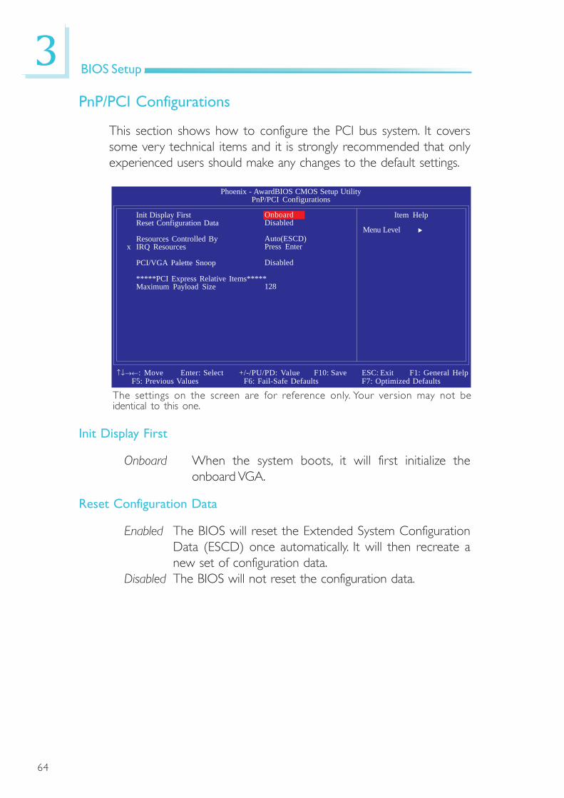
PnP/PCI Configurations
This section shows how to configure the PCI bus system. It coverssome very technical items and it is strongly recommended that onlyexperienced users should make any changes to the default settings.
Init Display First
Onboard When the system boots, it will first initialize theonboard VGA.
Reset Configuration Data
Enabled The BIOS will reset the Extended System ConfigurationData (ESCD) once automatically. It will then recreate anew set of configuration data.
Disabled The BIOS will not reset the configuration data.
The settings on the screen are for reference only. Your version may not beidentical to this one.
Phoenix - AwardBIOS CMOS Setup UtilityPnP/PCI Configurations
Item Help
Menu Level
↑↓→←: Move Enter: Select F1: General Help+/-/PU/PD: Value F10: Save ESC: ExitF5: Previous Values F6: Fail-Safe Defaults F7: Optimized Defaults
Init Display FirstReset Configuration Data
Resources Controlled Byx IRQ Resources
PCI/VGA Palette Snoop
*****PCI Express Relative Items*****Maximum Payload Size
OnboardDisabled
Auto(ESCD)Press Enter
Disabled
128

65
3BIOS Setup
Resources Controlled By
The Award Plug and Play BIOS has the capability to automaticallyconfigure all of the boot and Plug and Play compatible devices.
Auto(ESCD) The system will automatically detect the settings foryou.
Manual Choose the specific IRQ resources in the “IRQ Re-sources” field.
IRQ Resources
Move the cursor to this field and press <Enter>. Set each systeminterrupt to either PCI Device or Reserved.
PCI/VGA Palette Snoop
This field determines whether the MPEG ISA/VESA VGA cards canwork with PCI/VGA or not. The default value is Disabled.
Enabled MPEG ISA/VESA VGA cards work with PCI/VGA.Disabled MPEG ISA/VESA VGA cards does not work with PCI/
VGA.
Maximum Payload Size
This field is used to select the maximum TLP payload size of the PCIExpress devices. The unit is byte.
The settings on the screen are for reference only. Your version may not beidentical to this one.
Phoenix - AwardBIOS CMOS Setup UtilityIRQ Resources
Item Help
Menu Level
↑↓→←: Move Enter: Select F1: General Help+/-/PU/PD: Value F10: Save ESC: ExitF5: Previous Values F6: Fail-Safe Defaults F7: Optimized Defaults
IRQ-3 assigned toIRQ-4 assigned toIRQ-5 assigned toIRQ-7 assigned toIRQ-9 assigned toIRQ-10 assigned toIRQ-11 assigned toIRQ-12 assigned toIRQ-14 assigned toIRQ-15 assigned to
PCI DevicePCI DevicePCI DevicePCI DevicePCI DevicePCI DevicePCI DevicePCI DevicePCI DevicePCI Device
Legacy ISA for devicescompliant with theoriginal PC AT busspecification. PCI/ISAPnP for devicescompliant with the Plugand Play standardwhether designed forPCI or ISA busarchitecture.
66
3BIOS Setup
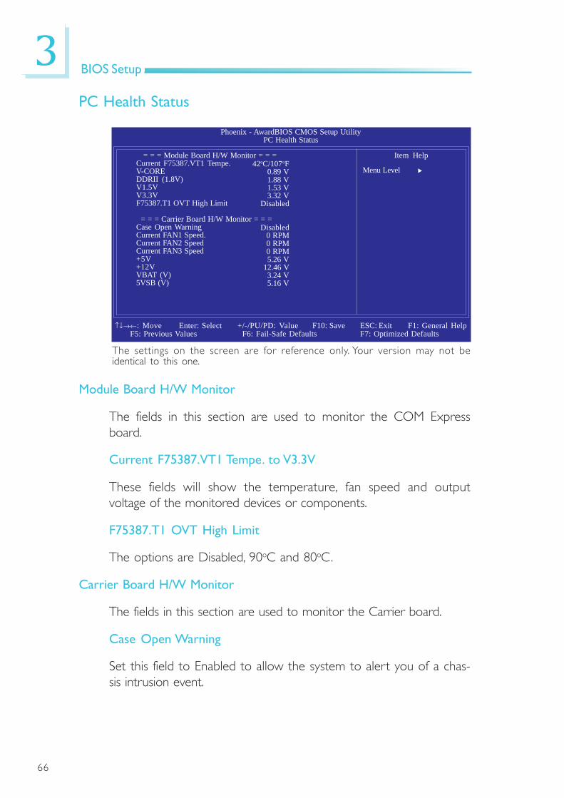
PC Health Status
The settings on the screen are for reference only. Your version may not beidentical to this one.
Module Board H/W Monitor
The fields in this section are used to monitor the COM Expressboard.
Current F75387.VT1 Tempe. to V3.3V
These fields will show the temperature, fan speed and outputvoltage of the monitored devices or components.
F75387.T1 OVT High Limit
The options are Disabled, 90oC and 80oC.
Carrier Board H/W Monitor
The fields in this section are used to monitor the Carrier board.
Case Open Warning
Set this field to Enabled to allow the system to alert you of a chas-sis intrusion event.
Phoenix - AwardBIOS CMOS Setup UtilityPC Health Status
Item Help
Menu Level
= = = Module Board H/W Monitor = = =Current F75387.VT1 Tempe.V-COREDDRII (1.8V)V1.5VV3.3VF75387.T1 OVT High Limit
= = = Carrier Board H/W Monitor = = =Case Open WarningCurrent FAN1 Speed.Current FAN2 SpeedCurrent FAN3 Speed+5V+12VVBAT (V)5VSB (V)
42oC/107oF0.89 V1.88 V1.53 V3.32 V
Disabled
Disabled0 RPM0 RPM0 RPM5.26 V
12.46 V3.24 V5.16 V
↑↓→←: Move Enter: Select F1: General Help+/-/PU/PD: Value F10: Save ESC: ExitF5: Previous Values F6: Fail-Safe Defaults F7: Optimized Defaults

67
3BIOS Setup
Load Fail-Safe Defaults
The “Load Fail-Safe Defaults” option loads the troubleshooting de-fault values permanently stored in the ROM chips. These settings arenot optimal and turn off all high performance features. You shoulduse these values only if you have hardware problems. Highlight thisoption in the main menu and press <Enter>.
If you want to proceed, type <Y> and press <Enter>. The defaultsettings will be loaded.
Phoenix - AwardBIOS CMOS Setup Utility
Esc : QuitF10 : Save & Exit Setup
↑ ↓ → ← : Select Item
Load Fail-Safe Defaults
Standard CMOS Features
Advanced BIOS Features
Advanced Chipset Features
Integrated Peripherals
Power Management Setup
PnP/PCI Configurations
PC Health Status
Load Fail-Safe Defaults
Load Optimized Defaults
Set Supervisor Password
Set User Password
Save & Exit Setup
Exit Without SavingLoad Fail-Safe Defaults (Y/N)?
Current FAN1 Speed to 5VSB(V)
These fields will show the fan speed and output voltage of themonitored devices or components.

68
3BIOS Setup
Load Optimized Defaults
The “Load Optimized Defaults” option loads optimized settings fromthe BIOS ROM. Use the default values as standard values for yoursystem. Highlight this option in the main menu and press <Enter>.
Type <Y> and press <Enter> to load the Setup default values.
Phoenix - AwardBIOS CMOS Setup Utility
Esc : QuitF10 : Save & Exit Setup
↑ ↓ → ← : Select Item
Load Optimized Defaults
Standard CMOS Features
Advanced BIOS Features
Advanced Chipset Features
Integrated Peripherals
Power Management Setup
PnP/PCI Configurations
PC Health Status
Load Fail-Safe Defaults
Load Optimized Defaults
Set Supervisor Password
Set User Password
Save & Exit Setup
Exit Without SavingLoad Optimized Defaults (Y/N)?
69
3BIOS Setup
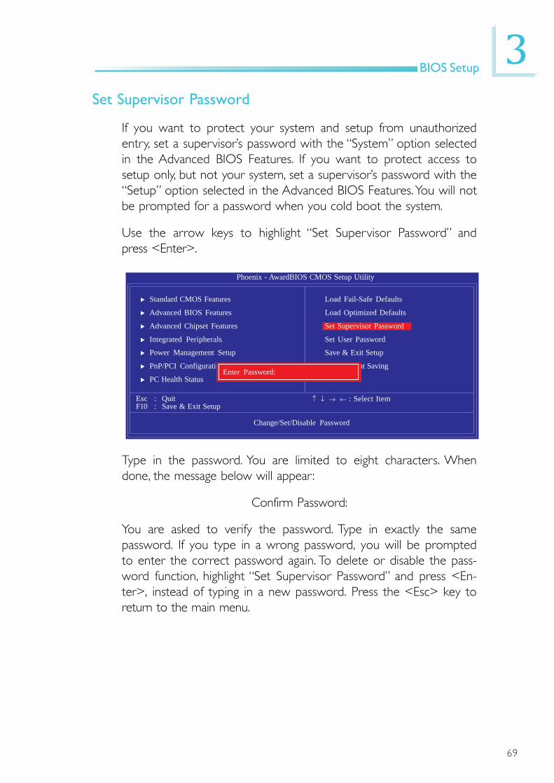
Set Supervisor Password
If you want to protect your system and setup from unauthorizedentry, set a supervisor’s password with the “System” option selectedin the Advanced BIOS Features. If you want to protect access tosetup only, but not your system, set a supervisor’s password with the“Setup” option selected in the Advanced BIOS Features. You will notbe prompted for a password when you cold boot the system.
Use the arrow keys to highlight “Set Supervisor Password” andpress <Enter>.
Type in the password. You are limited to eight characters. Whendone, the message below will appear:
Confirm Password:
You are asked to verify the password. Type in exactly the samepassword. If you type in a wrong password, you will be promptedto enter the correct password again. To delete or disable the pass-word function, highlight “Set Supervisor Password” and press <En-ter>, instead of typing in a new password. Press the <Esc> key toreturn to the main menu.
Phoenix - AwardBIOS CMOS Setup Utility
Esc : QuitF10 : Save & Exit Setup
↑ ↓ → ← : Select Item
Change/Set/Disable Password
Standard CMOS Features
Advanced BIOS Features
Advanced Chipset Features
Integrated Peripherals
Power Management Setup
PnP/PCI Configurations
PC Health Status
Load Fail-Safe Defaults
Load Optimized Defaults
Set Supervisor Password
Set User Password
Save & Exit Setup
Exit Without SavingEnter Password:
70
3BIOS Setup
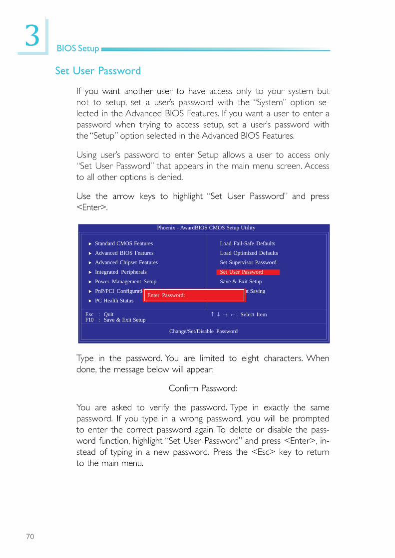
Set User Password
If you want another user to have access only to your system butnot to setup, set a user’s password with the “System” option se-lected in the Advanced BIOS Features. If you want a user to enter apassword when trying to access setup, set a user’s password withthe “Setup” option selected in the Advanced BIOS Features.
Using user’s password to enter Setup allows a user to access only“Set User Password” that appears in the main menu screen. Accessto all other options is denied.
Use the arrow keys to highlight “Set User Password” and press<Enter>.
Type in the password. You are limited to eight characters. Whendone, the message below will appear:
Confirm Password:
You are asked to verify the password. Type in exactly the samepassword. If you type in a wrong password, you will be promptedto enter the correct password again. To delete or disable the pass-word function, highlight “Set User Password” and press <Enter>, in-stead of typing in a new password. Press the <Esc> key to returnto the main menu.
Phoenix - AwardBIOS CMOS Setup Utility
Esc : QuitF10 : Save & Exit Setup
↑ ↓ → ← : Select Item
Change/Set/Disable Password
Standard CMOS Features
Advanced BIOS Features
Advanced Chipset Features
Integrated Peripherals
Power Management Setup
PnP/PCI Configurations
PC Health Status
Load Fail-Safe Defaults
Load Optimized Defaults
Set Supervisor Password
Set User Password
Save & Exit Setup
Exit Without SavingEnter Password:

71
3BIOS Setup
Save & Exit Setup
When all the changes have been made, highlight “Save & Exit Setup”and press <Enter>.
Type “Y” and press <Enter>. The modifications you have made willbe written into the CMOS memory, and the system will reboot. Youwill once again see the initial diagnostics on the screen. If you wish tomake additional changes to the setup, press <Ctrl> <Alt> <Del>simultaneously after memory testing is done.
Phoenix - AwardBIOS CMOS Setup Utility
Esc : QuitF10 : Save & Exit Setup
↑ ↓ → ← : Select Item
Save Data to CMOS
Standard CMOS Features
Advanced BIOS Features
Advanced Chipset Features
Integrated Peripherals
Power Management Setup
PnP/PCI Configurations
PC Health Status
Load Fail-Safe Defaults
Load Optimized Defaults
Set Supervisor Password
Set User Password
Save & Exit Setup
Exit Without SavingSAVE to CMOS and EXIT (Y/N)?

72
3BIOS Setup
Exit Without Saving
When you do not want to save the changes you have made, high-light “Exit Without Saving” and press <Enter>.
Type “Y” and press <Enter>. The system will reboot and you willonce again see the initial diagnostics on the screen. If you wish tomake any changes to the setup, press <Ctrl> <Alt> <Del> simul-taneously after memory testing is done.
Phoenix - AwardBIOS CMOS Setup Utility
Esc : QuitF10 : Save & Exit Setup
↑ ↓ → ← : Select Item
Abandon All Data
Standard CMOS Features
Advanced BIOS Features
Advanced Chipset Features
Integrated Peripherals
Power Management Setup
PnP/PCI Configurations
PC Health Status
Load Fail-Safe Defaults
Load Optimized Defaults
Set Supervisor Password
Set User Password
Save & Exit Setup
Exit Without SavingQuit Without Saving (Y/N)? N

73
3BIOS Setup
To update the BIOS, you will need the new BIOS file and a flashutility, AWDFLASH.EXE. Please contact technical support or yoursales representative for the files.
1. Save the new BIOS fi le along with the flash uti l ityAWDFLASH.EXE to a floppy disk.
2. Reboot the system and enter the Award BIOS Setup Utility toset the first boot drive to “Floppy”.
3. Save the setting and reboot the system.
4. After the system booted from the floppy disk, execute the flashutility by typing AWDFLASH.EXE. The following screen will appear.
5. Type the new BIOS file name onto the gray area that is next to“File Name to Program” then press <Enter>.
Award BIOS Flash Utility V.8.15B(C) Phoenix Technologies Ltd. All Rights Reserved.
(The current BIOS information will appear in this area.)
File Name to Program :
Updating the BIOS

74
3BIOS Setup
6. The following will appear.
Do You Want to Save BIOS (Y/N)
This question refers to the current existing BIOS in your system.We recommend that you save the current BIOS and its flashutility; just in case you need to reinstall the BIOS. To save thecurrent BIOS, press <Y> then enter the file name of the currentBIOS. Otherwise, press <N>.
7. The following will then appear.
Press “Y” to Program or “N” to Exit
8. Press <Y> to flash the new BIOS.

75
4Supported Software
The CD that came with the system board contains drivers, utilitiesand software applications required to enhance the performance ofthe system board.
Inser t the CD into a CD-ROM drive. The autorun screen(Mainboard Utility CD) will appear. If after inser ting the CD,"Autorun" did not automatically start (which is, the Mainboard UtilityCD screen did not appear), please go directly to the root directoryof the CD and double-click "Setup".
Chapter 4 - Supported Software

76
4Supported Software
2. Read the l icenseagreement then click Yes.
Intel Chipset Software Installation Utility
The Intel Chipset Software Installation Utility is used for updatingWindows® INF files so that the Intel chipset can be recognized andconfigured properly in the system.
To install the utility, click “Intel Chipset Software Installation Utility” on themain menu.
1. Setup is now ready toinstall the utility. ClickNext.
Drivers for Windows Vista System
77
4Supported Software
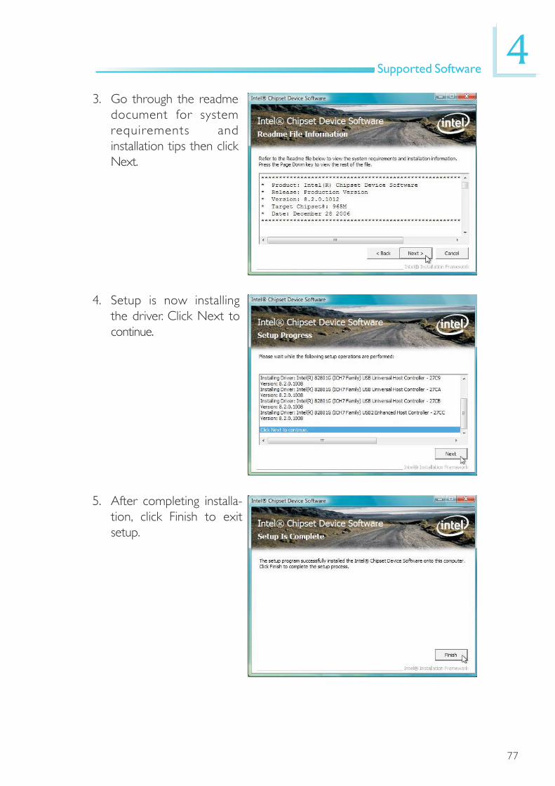
3. Go through the readmedocument for systemrequirements andinstallation tips then clickNext.
4. Setup is now installingthe driver. Click Next tocontinue.
5. After completing installa-tion, click Finish to exitsetup.

78
4Supported Software
Intel Graphics Drivers
To install the utility, click “Intel Graphics Drivers” on the main menu.
1. Setup is now ready toinstall the graphics driver.Click Next.
2. Read the l icenseagreement then click Yes.

79
4Supported Software
3. Go through the readmedocument for systemrequirements andinstallation tips then clickNext.
4. Setup is now installingthe driver. Click Next tocontinue.
5. Click “Yes, I want torestar t this computernow” then click Finish.
Restarting the system willallow the new softwareinstallation to take effect.
80
4Supported Software
Audio Drivers
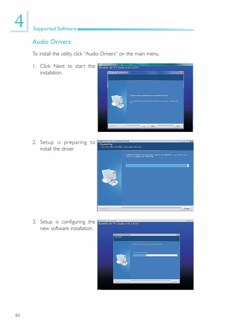
To install the utility, click “Audio Drivers” on the main menu.
1. Click Next to start theinstallation.
2. Setup is preparing toinstall the driver.
3. Setup is configuring thenew software installation.
81
4Supported Software
5. Click “Yes, I want torestar t my computernow” then click Finish.
Restar ting the systemwill al low the newsoftware installation totake effect.
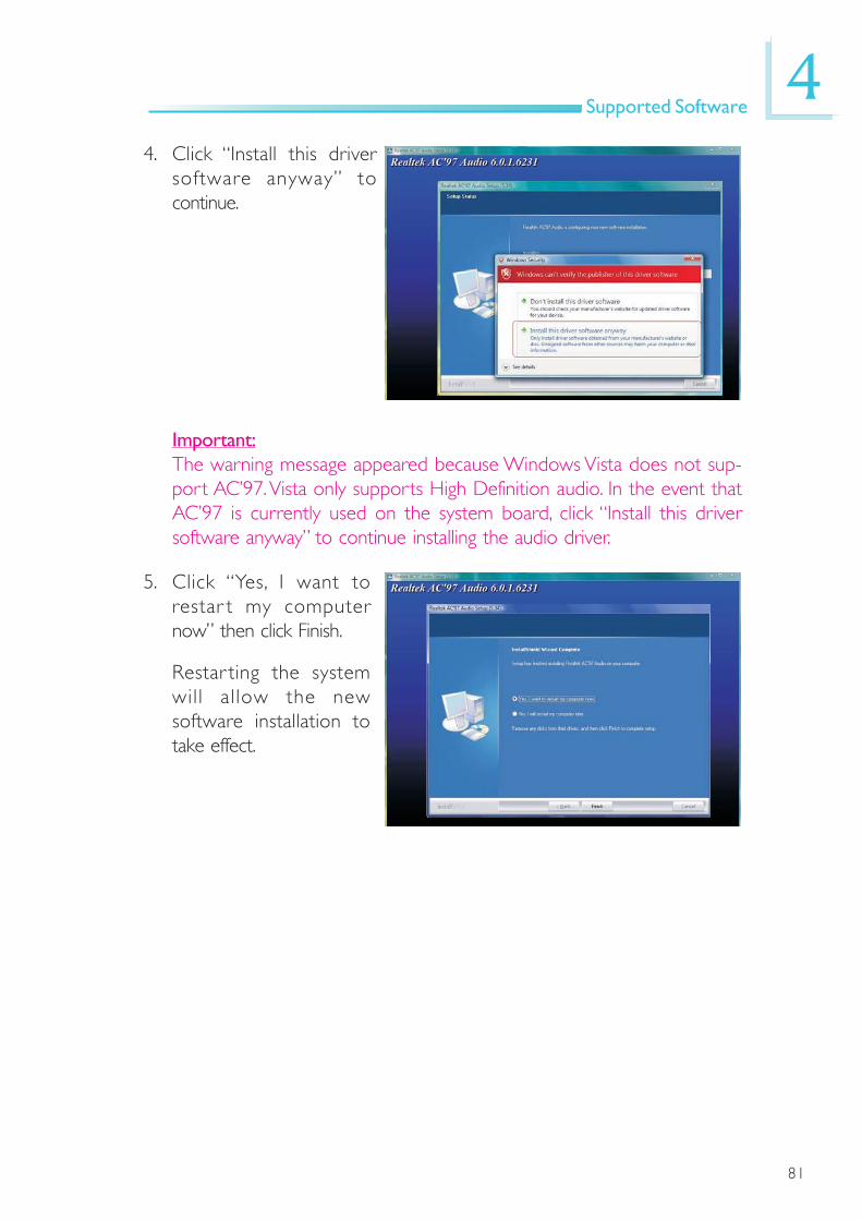
Important:The warning message appeared because Windows Vista does not sup-port AC’97. Vista only supports High Definition audio. In the event thatAC’97 is currently used on the system board, click “Install this driversoftware anyway” to continue installing the audio driver.
4. Click “Install this driversoftware anyway” tocontinue.

82
4Supported Software
LAN Drivers
To install the driver, click “LAN Drivers” on the main menu.
1. Setup is now ready toinstall the driver. ClickNext.
2. Click Install to begininstallation.

83
4Supported Software
3. After completing installa-tion, click Finish to exitsetup.

84
4Supported Software
MyGuard Hardware Monitor
To install the utility, click “MyGuard Hardware Monitor” on the main menu.
1. Setup is now ready toinstall the utility. ClickNext.
2. Click Install to begininstallation.
3. Setup is currently installingthe utility.

85
4Supported Software
4. After completing installa-tion, click Finish to exitsetup.

86
4Supported Software
Hardware Monitor for Windows
The system board comes with the Hardware Monitor for Windows utility.This utility is capable of monitoring the system’s temperature, fan speed,voltage, etc. and allows you to manually set a range (Highest and LowestLimit) to the items being monitored. If the settings/values are over orunder the set range, a warning message will pop-up. The utility can also beconfigured so that a beeping alarm will sound whenever an error occurs.We recommend that you use the “Default Setting” which is the ideal set-ting that would keep the system in good working condition.
To install the utility, click “Hardware Monitor for Windows” on the mainmenu.
1. Click Yes to continue.
2. Setup is now ready toinstall the utility. ClickNext.
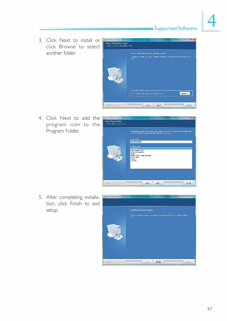
87
4Supported Software
5. After completing installa-tion, click Finish to exitsetup.
4. Click Next to add theprogram icon to theProgram Folder.
3. Click Next to install orclick Browse to selectanother folder.

88
4Supported Software
6. Click Yes if you want tocreate a HardwareDoctor shortcut at yourdesktop.
7. Click “Yes, I want torestar t my computernow” then click Finish.
Restarting the system willallow the utility to takeeffect.

89
4Supported Software
Using the Hardware Monitor for Windows Utility
1. When you try to run theutility, which is usuallydone by double-clickingthe Hardware Doctorshor tcut, an errormessage will appear.
2. To solve this problem,right-click the HardwareDoctor shor tcut. thenselect Properties.
3. Select the Compatibilitytab, click “Run this pro-gram as an administra-tor” then click OK.
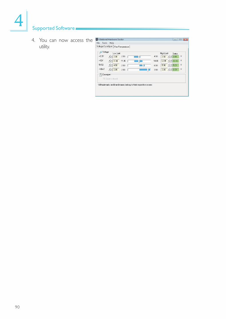
90
4Supported Software
4. You can now access theutility.
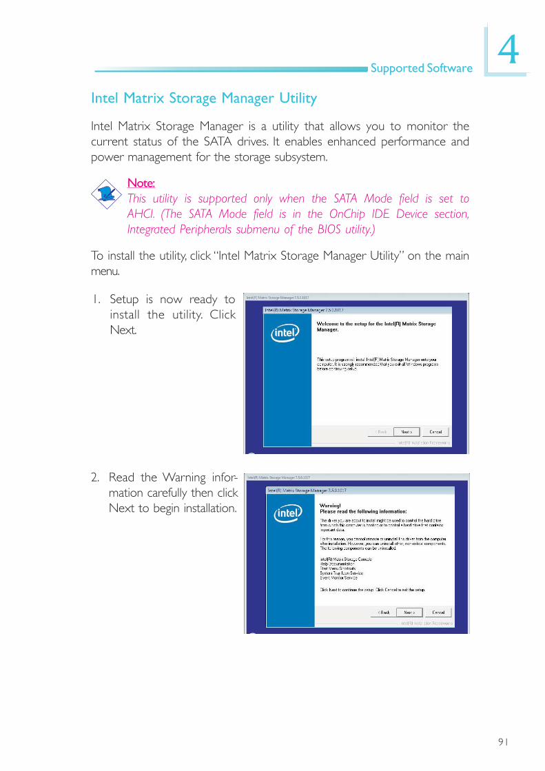
91
4Supported Software
Intel Matrix Storage Manager Utility
Intel Matrix Storage Manager is a utility that allows you to monitor thecurrent status of the SATA drives. It enables enhanced performance andpower management for the storage subsystem.
Note:This utility is supported only when the SATA Mode field is set toAHCI. (The SATA Mode field is in the OnChip IDE Device section,Integrated Peripherals submenu of the BIOS utility.)
To install the utility, click “Intel Matrix Storage Manager Utility” on the mainmenu.
1. Setup is now ready toinstall the utility. ClickNext.
2. Read the Warning infor-mation carefully then clickNext to begin installation.
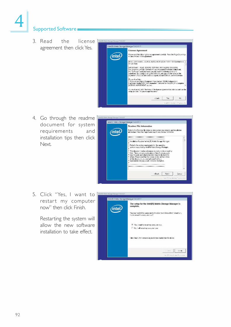
92
4Supported Software
3. Read the l icenseagreement then click Yes.
4. Go through the readmedocument for systemrequirements andinstallation tips then clickNext.
5. Click “Yes, I want torestar t my computernow” then click Finish.
Restarting the system willallow the new softwareinstallation to take effect.

93
4Supported Software
Installing the AHCI Driver During Windows Vista Installation
The AHCI driver must be installed during Windows® Vista installation.This is required in order to install the operating system onto a harddrive when in AHCI mode.
1. Star t Windows Setupby booting from theinstallation CD. Followthe steps on the screen.
When the screen onthe right appears, clickCustom (advanced).
2. Select Load Driver.
3. Inser t the providedfloppy diskette thenclick OK.
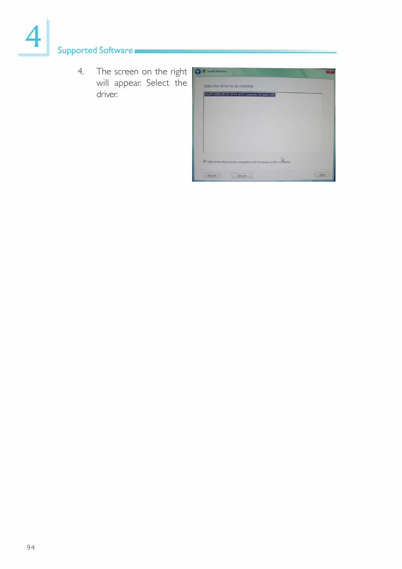
94
4Supported Software
4. The screen on the rightwill appear. Select thedriver.

95
4Supported Software
1. Click Next to continue.
2. Setup is now ready toinstall. Click Next.
Adobe Acrobat Reader 7.0 (English Version)
To install, click “Adobe Acrobat Reader 7.0 (English Version)” on the mainmenu.
3. Click Next to install orclick Change DestinationFolder to select anotherfolder.

96
4Supported Software
5. Click Finish to exitinstallaion.
4. Click Install to begininstallation.
97
4Supported Software
Creating an AHCI Driver Floppy Diskette under Vista
The system board package includes floppy diskettes which are neededwhen you install the AHCI driver during Windows Vista installation. If in anycase you lost the diskette, you can create another one by following thesteps below.
1. Insert the provided CD into a CD-ROM drive.
2. The execution files are located in:
drive:>\AHCI_RAID\F6FLOPPY
3. Run f6flpy32.exe (for 32-bit system) or f6flpy64.exe (for 64-bitsystem).
4. Insert a blank floppy diskette then click OK.
5. The system will format and write the necessary driver files into thediskette.
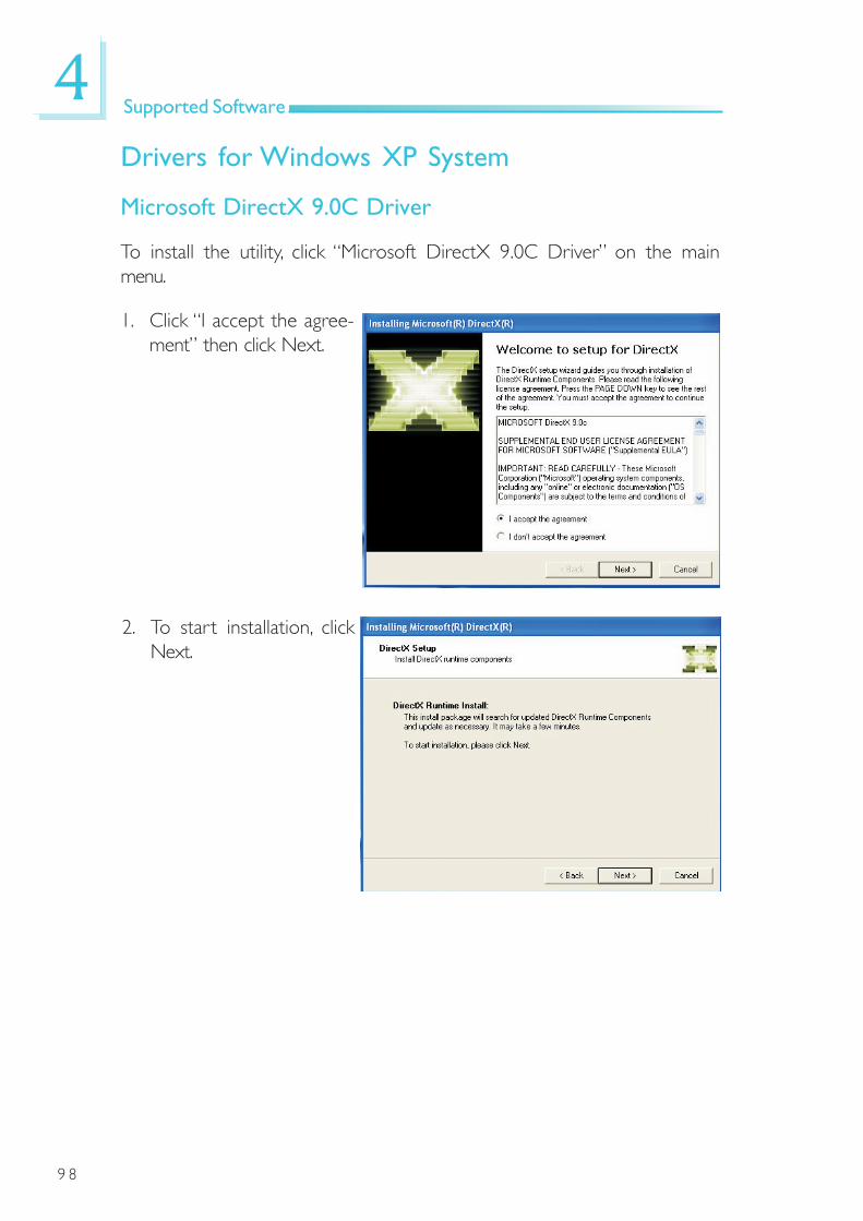
9 8
4Supported Software
1. Click “I accept the agree-ment” then click Next.
Microsoft DirectX 9.0C Driver
To install the utility, click “Microsoft DirectX 9.0C Driver” on the mainmenu.
Drivers for Windows XP System
2. To start installation, clickNext.

9 9
4Supported Software
3. Click Finish. Reboot thesystem for DirectX totake effect.

100
4Supported Software
Intel Chipset Software Installation Utility
The Intel Chipset Software Installation Utility is used for updatingWindows® INF files so that the Intel chipset can be recognized andconfigured properly in the system.
To install the utility, click “Intel Chipset Software Installation Utility” on themain menu.
1. Setup is now ready toinstall the utility. ClickNext.
2. Read the l icenseagreement then click Yes.

101
4Supported Software
3. Go through the readmedocument for systemrequirements andinstallation tips then clickNext.
4. Setup is now installingthe driver. Click Next tocontinue.
5. Click “Yes, I want torestar t this computernow” then click Finish.
Restar ting the systemwill al low the newsoftware installation totake effect.
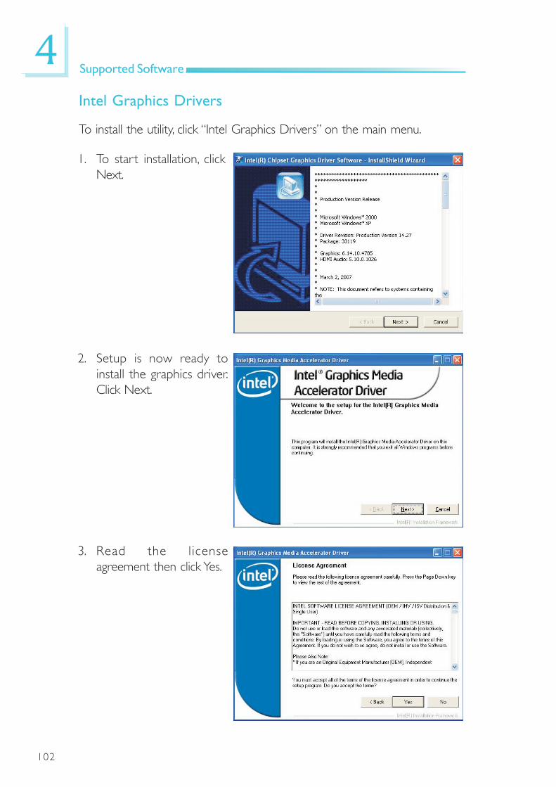
102
4Supported Software
Intel Graphics Drivers
To install the utility, click “Intel Graphics Drivers” on the main menu.
2. Setup is now ready toinstall the graphics driver.Click Next.
1. To start installation, clickNext.
3. Read the l icenseagreement then click Yes.
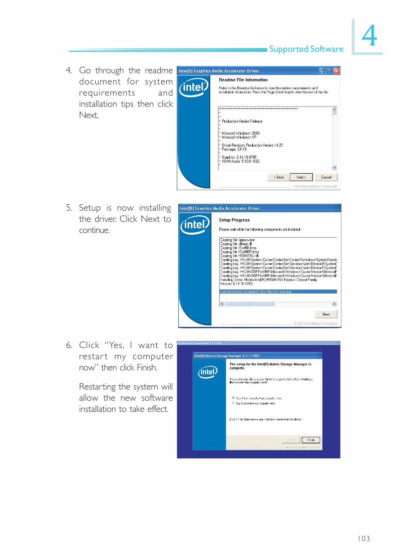
103
4Supported Software
6. Click “Yes, I want torestar t my computernow” then click Finish.
Restarting the system willallow the new softwareinstallation to take effect.
4. Go through the readmedocument for systemrequirements andinstallation tips then clickNext.
5. Setup is now installingthe driver. Click Next tocontinue.

104
4Supported Software
Audio Drivers
To install the utility, click “Audio Drivers” on the main menu.
1. Setup is now ready toinstall the audio driver.Click Next.
2. Follow the remainder ofthe steps that appearedon the screen; clicking“next” each time youfinish a step.
3. Click “Yes, I want torestar t my computernow” then click Finish.
Restar ting the systemwill al low the newsoftware installation totake effect.
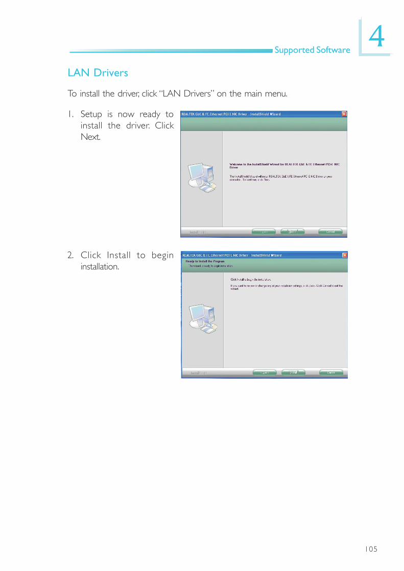
105
4Supported Software
LAN Drivers
To install the driver, click “LAN Drivers” on the main menu.
1. Setup is now ready toinstall the driver. ClickNext.
2. Click Install to begininstallation.

106
4Supported Software
3. After completing installa-tion, click Finish to exitsetup.

107
4Supported Software
MyGuard Hardware Monitor
To install the utility, click “MyGuard Hardware Monitor” on the main menu.
1. Setup is now ready toinstall the utility. ClickNext.
2. Click Install to begininstallation.
3. Setup is currently installingthe utility.
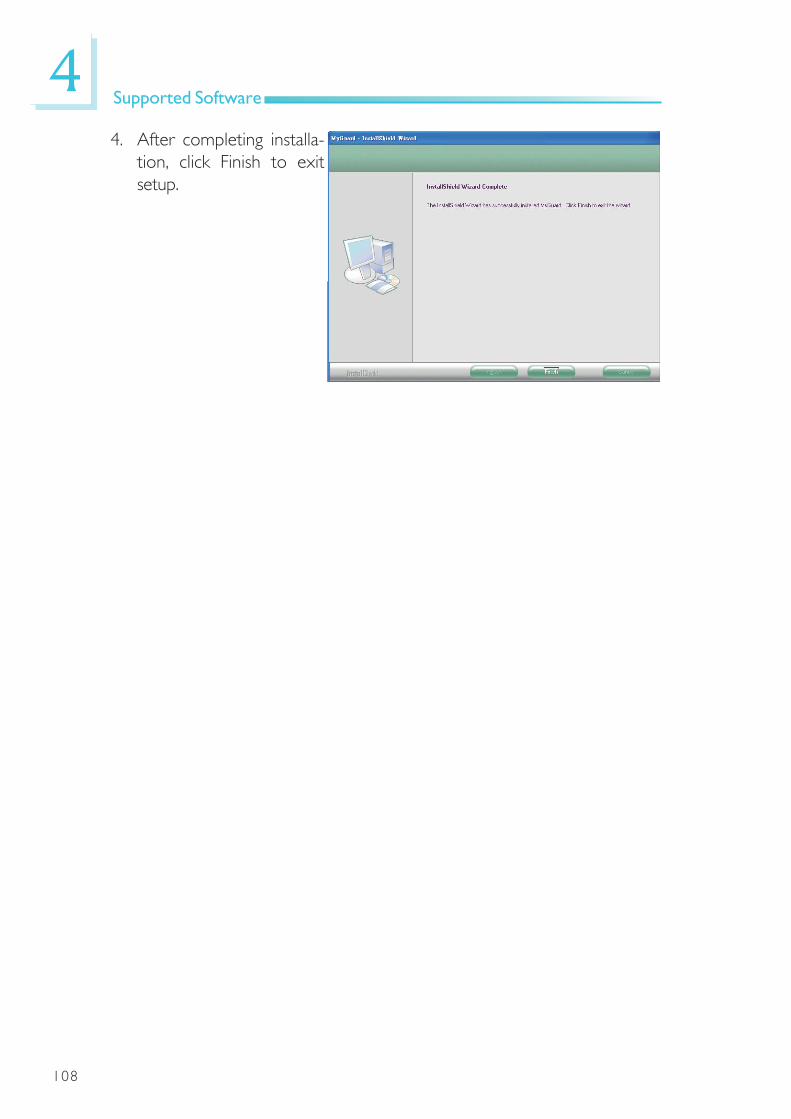
108
4Supported Software
4. After completing installa-tion, click Finish to exitsetup.

109
4Supported Software
2. Click Next to install orclick Browse to selectanother folder.
Hardware Monitor for Windows
The system board comes with the Hardware Monitor for Windows utility.This utility is capable of monitoring the system’s temperature, fan speed,voltage, etc. and allows you to manually set a range (Highest and LowestLimit) to the items being monitored. If the settings/values are over orunder the set range, a warning message will pop-up. The utility can also beconfigured so that a beeping alarm will sound whenever an error occurs.We recommend that you use the “Default Setting” which is the ideal set-ting that would keep the system in good working condition.
To install the utility, click “Hardware Monitor for Windows” on the mainmenu.
1. Setup is now ready toinstall the utility. ClickNext.
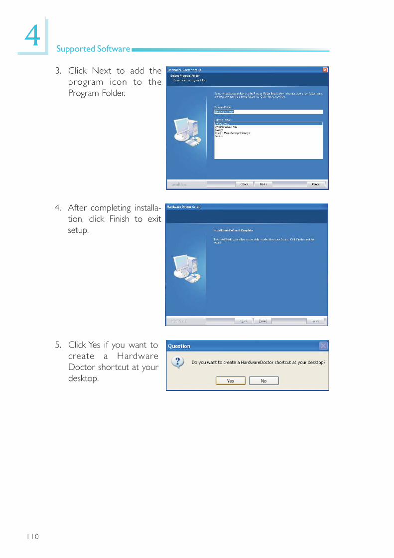
110
4Supported Software
3. Click Next to add theprogram icon to theProgram Folder.
4. After completing installa-tion, click Finish to exitsetup.
5. Click Yes if you want tocreate a HardwareDoctor shortcut at yourdesktop.

111
4Supported Software
6. Click “Yes, I want torestar t my computernow” then click Finish.
Restarting the system willallow the driver to takeeffect.

112
4Supported Software
1. Setup is now ready toinstall the utility. ClickNext.
2. Read the Warning infor-mation carefully then clickNext.
Intel Matrix Storage Manager Utility
Intel Matrix Storage Manager is a utility that allows you to monitor thecurrent status of the SATA drives. It enables enhanced performance andpower management for the storage subsystem.
Note:This utility is supported only when the SATA Mode field is set toAHCI. (The SATA Mode field is in the OnChip IDE Device section,Integrated Peripherals submenu of the BIOS utility.)
To install the utility, click “Intel Matrix Storage Manager Utility” on the mainmenu.

113
4Supported Software
3. Read the l icenseagreement then click Yes.
4. Go through the readmedocument for systemrequirements andinstallation tips then clickNext.
5. Click “Yes, I want torestar t my computernow” then click Finish.
Restarting the system willallow the new softwareinstallation to take effect.

114
4Supported Software
AHCI for F6 During Windows Setup Floppy Driver
This is used to create a floppy driver diskette needed when you installWindows® XP using the F6 installation method. This will allow you to installthe operating system onto a hard drive when in AHCI mode.
Click “AHCI for F6 During Windows Setup Floppy Driver” on the mainmenu.
1. Inser t a blank floppydiskette then click OK.
2. Make sure you have abackup of the data inthe disk. Clicking Yes willerase all data.
3. The system is currentlyformatting and writingthe necessary driver filesinto the diskette.

115
4Supported Software
1. Click Next to continue.
2. Setup is now ready toinstall. Click Next.
Adobe Acrobat Reader 7.0 (English Version)
To install, click “Adobe Acrobat Reader 7.0 (English Version)” on the mainmenu.
3. Click Next to install orclick Change DestinationFolder to select anotherfolder.
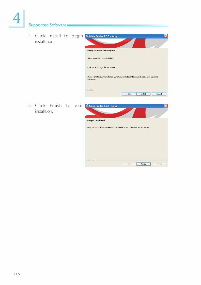
116
4Supported Software
5. Click Finish to exitinstallaion.
4. Click Install to begininstallation.

117
4Supported Software
Installing the AHCI Driver During Windows XP Installation
The AHCI driver must be installed during the Windows® XPinstallation using the F6 installation method. This is required in orderto install the operating system onto a hard drive when in AHCImode.
1. Start Windows Setup by booting from the installation CD.
2. Press <F6> when prompted in the status line with the ‘PressF6 if you need to install a third party driver’ message.
3. Press <S> to “Specify Additional Device”.
4. At this point you will be prompted to insert a floppy diskcontaining the AHCI driver. Insert the provided floppy diskette.
5. Locate for the drive where you inserted the diskette then selectAHCI controller that corresponds to your BIOS setup. Press<Enter> to confirm.
You have successfully installed the driver. However you must continueinstalling the OS. Leave the floppy disk in the floppy drive until thesystem reboots itself because Windows setup will need to copy thefiles again from the floppy disk to the Windows installation folders.After Windows setup has copied these files again, remove the floppydiskette so that Windows setup can reboot as needed.

118
AWatchdog Timer
Appendix A - Watchdog Timer
Watchdog Timer
The following parameters are references for setting the time intervalof the Watchdog Timer function. The system will regularly be “cleared”according to the set time interval. If the system hangs or fails tofunction, it will also reset according to the time interval so that yoursystem will continue to operate.
.model small
.386
;-------------------;Port defination;-------------------SuperIo_CFG_Port EQU 2Eh ;Super I/O Config port. (2Eh/4Eh)SuperIo_DAT_Port EQU SuperIo_CFG_Port + 1
WDT_Counter EQU 10 ; 1 to 255 (Sec./Min), 0 meansdisabled
mSuperio_Enter_Config Macromov dx, SuperIo_CFG_Portmov al, 87hout dx, alNEWIODELAYout dx, al
endM
mSuperio_Exit_Config Macromov dx, SuperIo_CFG_Portmov al, 0AAhout dx, al
endM

119
AWatchdog Timer
mSuperio_GetSet_Reg Macro RegIndex, AndMask, OrValuemov dx, SuperIo_CFG_Portmov al, RegIndexout dx, alNEWIODELAYmov dx, SuperIo_DAT_Portin al, dxNEWIODELAYmov ah, aland al, AndMaskor al, OrValueout dx, alNEWIODELAY
endM
mSuperio_Get_Reg Macro RegIndexmov dx, SuperIo_CFG_Portmov al, RegIndexout dx, alNEWIODELAYmov dx, SuperIo_DAT_Portin al, dxNEWIODELAY
endM
mSuperio_LDN_Select Macro LDNmSuperio_Set_Reg07h, LDN
endM
mSuperio_Set_Reg Macro RegIndex, SetValuemov dx, SuperIo_CFG_Portmov al, RegIndexout dx, alNEWIODELAYmov dx, SuperIo_DAT_Portmov al, SetValueout dx, alNEWIODELAY
endM

120
AWatchdog Timer
NEWIODELAY Macroout 0EBh, al ;Dummy I/O output for delay
endM
.code
start:call W83627Hx_WDT
mov ah, 4chint 21h
W83627Hx_WDT Proc near;LDN8;CRF5[3] :RW 0/1 = WDTO Second/Minute;CRF5[2] :RW 0/1 = Keyboard Reset Low/High when WDTOTimeout;CRF6[7:0]:RW 00h = Disable , 01h~0FFh = 1~255 Sec/Min.;CRF7[7] :RW 0/1 = Disable/Enable Mouse interrupt reset WDTOcounting.;CRF7[6] :RW 0/1 = Disable/Enable Keyboard interrupt resetWDTO counting.;CRF7[5] :WO 1 = Force WDTO time out(Auto clear).;CRF7[4] :RW 0/1 = WDTO time status TimeOut/Counting.;CRF7[3:0]:RW 0~7 = Low IRQ for WDTO (Typical is 2, meansSMI).
mSuperio_Enter_Config
mSuperio_LDN_Select 08h
; PLED mode register, WDTO time unit as second, Keyboard resetwhen WDTO time out
mSuperio_GetSet_Reg 0F5h, 11110111b, 00000100b; , Disable MS/KB interrupt reset WDTO counting, IRQ2 for WDTO
mSuperio_GetSet_Reg 0F7h, 11111111b, 11000010b; , WDTO Time out Value
mSuperio_Set_Reg 0F6h, WDT_Counter

121
AWatchdog Timer
mSuperio_Exit_Config@@:
ret
W83627Hx_WDT endP
end start