noŽovÉ posÚvaČe medziprÍrubovÉ typ a
TRANSCRIPT

• jednodielne liate teleso bez prírub (wafer) s krátkou stavebnou dĺžkou
• plný prietok • nôž so špeciálnym vedením pre rýchle a bezproblémové
uzatváranie • kovové alebo mäkké jednostranne tesniace sedlo • stúpajúce vreteno • široká ponuka materiálových variantov výmenných mäkkých sediel • nízky ovládací moment
OBLASTI POUŽITIA:
• čističky odpadových vôd, kalové hospodárstvo • papierenský priemysel • potravinársky priemysel • chemický priemysel • skladovanie a preprava sypkých materiálov
VÝHODY POUŽITIA:
• nízka tlaková strata • nízka hmotnosť • jednoduchá inštalácia medzi príruby do potrubia alebo na koniec
potrubia (pod výsypky) • nízke náklady na údržbu• dlhá životnosť
TECHNICKÉ ÚDAJE:
Pracovné médiá: kvapalné médiá s koncentráciou pevných častíc maximálne 5% (napr. znečistené kvapaliny, odpadné vody a kaly, papierovina ) alebo sypké médiá (prášky, granuláty), u ktorých veľkosť mechanických častíc nepresahuje 10 mm, v závislosti na konštrukčných materiáloch nožo- vého posúvača
Maximálny pracovný tlak:
www.intermos.sk
TYP ADN 50 ÷ 1200/ PN 10
NOŽOVÉ POSÚVAČE MEDZIPRÍRUBOVÉ
Verzia 20.04.00
DN Max. pracovný tlak (bar)
50 - 150 10200 8
250 - 300 6350 - 400 5450 - 600 3700 - 1200 2
Tieto hodnoty max. pracovného tlaku sú platné pre nožové posúvače nainštalované s šípkou na telese zhodne so smerom prúdenia pracovnej látky v potrubí. V prípade gravitačného prúdenia sypkých médií (inštalácia armatúr pod výsypkami) sa nožové posúvače inštalujú s šípkou na telese v opačnom smere než je prúdenie pracovného média a maximálny pracovný tlak je len 30% hodnôt uvedených vyššie.
• jednodielne liate teleso bez prírub (wafer) s krátkou
• •
• • • •
OBLASTI POUŽITIA:
• • • • •
VÝHODY POUŽITIA:
• • • jednoduchá inštalácia medzi príruby do potrubia alebo na koniec
• •

INTERMOS VALVES, s.r.o. www.intermos.sk
Maximálny teplotný rozsah: závisí na konštrukcii a konštrukčných materiáloch nožového posúvača, pracovnom médiu a pracovných podmienkach
Typy sediel a ich tesnosť:
K N I F E - G A T E V A L V E S A S E R I E S
C.M.O. Amategui Aldea 142, 20400 Txarama‐Tolosa (SPAIN) TEC‐A.EN07
Tel. Nacional: 902.40.80.50 Fax: 902.40.80.51 / Tel. Internacional: 34.943.67.33.99 Fax: [email protected] http://www.cmo.esPage3
1‐ BODY Unidirectional wafer‐design knife gate valve. One‐piece cast body with guides to support gate and seat wedges. For diameters greater than ND1200 the body is machine‐welded with the necessary reinforcements to resist the maximum working pressure. Full port designed to provide high flow rates with low pressure drop. The body’s internal design prevents any build up of solids in the seat area. The standard manufacturing materials are GJL‐250 cast iron and CF8M stainless steel. Other materials, such as GJS‐500 nodular cast iron, A216WCB carbon steel and stainless steel alloys (AISI316Ti, Duplex, 254SMO, Uranus B6…) are available on request. As standard, iron or carbon steel valves are painted with an anti‐corrosive protection of 80 microns of EPOXY (colour RAL 5015). Other types of anti‐corrosive protections are available on request. 2‐ GATE The standard manufacturing materials are AISI304 stainless steel in valves with iron body and AISI316 stainless steel in valves with CF8M body. Other materials or combinations can be supplied on request. The gate is polished on both sides to provide a smooth contact surface with the resilient seat. At the same time, the gate is rounded to prevent the seat from being cut. Different degrees of polishing, anti‐abrasion treatments and modifications are available to adapt the valves to the customer’s requirements. 3‐ SEAT: (watertight)Six types of seats are available according to the working application: Seat 1: Metal / metal seat. This type of seat does not include any kind of resilient seat and the
estimated leakage (considering water as the test fluid) is 1.5% of the pipe flow. Seat 2: Standard soft‐seated valve. This type of seat includes a resilient seat which is fixed to the inside
of the body via an AISI316 stainless steel retaining ring. Seat 3: Soft‐seated valve with reinforced socket. This type of seat includes a resilient seat which is
fixed to the inside of the body via an AISI316 stainless steel retaining ring with two functions (to protect the valve from abrasion and clean the gate when working with solids that can stick to it).
DESIGN CHARACTERISTICS
fig. 3
K N I F E - G A T E V A L V E S A S E R I E S
C.M.O. Amategui Aldea 142, 20400 Txarama‐Tolosa (SPAIN) TEC‐A.EN07
Tel. Nacional: 902.40.80.50 Fax: 902.40.80.51 / Tel. Internacional: 34.943.67.33.99 Fax: [email protected] http://www.cmo.esPage4
Seats 4, 5 and 6: The same as seats 1, 2 and 3 but including a deflector. The deflector is a cone‐shaped ring located at the valve’s entrance with two functions (to protect the valve from abrasion and guide the flow to the centre of the valve).
Note: Three materials are available for the reinforced socket and the deflector (CA‐15 steel, CF8M and Ni‐hard).
Resilient seat materials EPDMThis is the standard resilient seat fitted on CMO valves. It can be used in many applications, however, it is generally used for water and products diluted in water at temperatures no higher than 90°C*. It can also be used with abrasive products and it provides the valve with 100% watertight integrity. NITRILEIt is used in fluids containing fats or oils at temperatures no higher than 90°C*. It provides the valve with 100% watertight integrity. VITON Suitable for corrosive applications and continuous high temperatures of up to 190°C and peaks of 210°C. It provides the valve with 100% watertight integrity. SILICONEMainly used in the food industry and for pharmaceutical products with temperatures no higher than 200°C. It provides the valve with 100% watertight integrity. PTFESuitable for corrosive applications and pH between 2 and 12. Does not provide the valve with 100% watertight integrity. Estimated leakage: 0.5% of the tube flow.
Note: In some applications other types of resilient materials are used, such as hypalon, butile or natural rubber. Please contact us if you require one of these materials. 4‐ PACKING CMO’s standard packing is composed of three lines with a specially designed EPDM O‐ring in the middle which provides watertight integrity between the body and the gate, preventing any type of leakage to the atmosphere. It is located in an easily accessible place and can be replaced without dismantling the valve from the pipeline. Below we indicate various types of packing available according to the application in which the valve is located:
fig. 4Typ sedla Tesnosť (%) 1 kov–kov (kovové) 98,82 kov–elastomér 100 3 kov–elastomér s krúžkom (scraperom) pre ochranu sedla pred abráziou 100 4 kov–kov s deflektorom pre ochranu telesa pred abráziou 98,85 kov–elastomér s deflektorom pre ochranu telesa pred abráziou 1006 kov–elastomér s ochranným krúžkom (scraperom) a deflektorom pre ochranu sedla a telesa pred abráziou 100
Pozn. Za účelom výberu vhodného typu sedla a materiálov telesa, noža, sedla a upchávky, prosíme, kontaktujte naše obchodné oddelenie.
Stavebná dĺžka: podľa výrobcu
Montáž medzi príruby: EN 1092-1 / DIN PN10
Ovládanie: DN 50 až DN 500 ........ ručné koleso DN 600 až DN 1200 ........ prevod s ručným kolesom Ďalšie možnosti: nestúpajúce vreteno predĺžené vreteno rýchlo uzatváracia páka reťazové koleso elektrický, pneumatický alebo hydraulický pohon uzamykacie zariadenie regulácia prietoku ukazovateľ polohy koncové spínače iné typy a farebné odtiene ochranných náterov dodávka vrátane protiprírub, tesnenia a spojovacieho materiálu
Obr. 1

INTERMOS VALVES, s.r.o. www.intermos.sk
Skúšanie: nožové posúvače sa skúšajú podľa normy EN 12266-1 a dodávajú so sprievodnou dokumentáciou podľa EN 10204
Certifikácia: PED 97/23/ES (PED 2014/68/EÚ) ATEX (III, 2 a 22 GD) 94/9/ES
Obr. 2
K N I F E - G A T E V A L V E S A S E R I E S
C.M.O. Amategui Aldea 142, 20400 Txarama‐Tolosa (SPAIN) TEC‐A.EN07
Tel. Nacional: 902.40.80.50 Fax: 902.40.80.51 / Tel. Internacional: 34.943.67.33.99 Fax: [email protected] http://www.cmo.esPage2
When a knife gate valve remains open for long periods of time and the body’s internal walls are parallel a very large torque is required to close it. Model A’s body is cone‐shaped inside, providing greater space. This way, when the valve is closed the solids stored inside it can be easily removed. This valve is defined as unidirectional and these valves are normally at risk of the gate bending due to counter‐pressure. This cannot happen with the CMO valve because it contains internal guides that support the knife gate and allow it to work under counter‐pressure of 30% of the maximum working pressure, without the knife gate bending. The stem protection hood is independent from the handwheel securing nut, this means the hood can be disassembled without the need to release the handwheel. This advantage allows regular maintenance operations to be performed, such as lubricating the stem, etc. The stem on the CMO valve is made of 18/8 stainless steel. This is another added advantage, as some manufacturers produce it with 13% chrome and it gets rusty very quickly. The handwheel is made of GJS‐500 nodular cast iron. Some manufacturers produce them in normal cast iron which can lead to breakages in the event of very high operating torque or knocks. The yoke is has a compact design with the bronze actuator nut protected in a sealed and lubricated box. This makes it possible to move the valve with a key, even without the handwheel (in other manufacturers’ products this is not possible). The pneumatic actuator’s upper and lower covers are made of GJS‐400 nodular cast iron, making them highly shock resistant. This characteristic is essential in pneumatic actuators. The pneumatic cylinder’s o‐ring seals are commercial products and can be purchased worldwide. This means it is not necessary to contact CMO every time a seal is required.
STANDARD COMPONENTS LISTCOMPONENT CAST IRON VERSION ST. STEEL VERSION1‐ Body GJL‐250 CF8M 2‐ Gate AISI304 AISI316 3‐ Guide RCH1000 4‐ Packing gland GJS‐500 CF8M 5‐ Packing SYNT + PTFE 6‐ O‐ring seal EPDM 7‐ Support plates S275JR 8‐ Ring AISI316 9‐ Seat EPDM 10‐ Stem AISI303 11‐ Yoke STEEL12‐ Stem nut BRONZE13‐ Check nut ST44.2 + ZINC 14‐ Handwheel NODULAR CAST IRON15‐ Nut STEEL16‐ Hood STEEL17‐ Top cap PLASTIC
Advantages of CMO’s "Model A" compared to similar products
fig. 2
table 1 fig. 2
Pozícia Popis Základné materiálové varianty posúvača s mäkkým sedlom
1 Teleso GJL-2501*) CF8M2 Nôž AISI 304 AISI 316 3 Vedenie noža RCH10004 Upchávkové veko GJS-500*) CF8M5 Upchávka Synt. + PTFE 6 O-krúžok EPDM 7 Strmeňová doska S275JR 8 Kovový krúžok AISI 3169 Sedlo EPDM10 Vreteno AISI 30311 Strmeň oceľ 12 Vretenová matica bronz 13 Matica ST44.2 pozink.14 Ručné koleso GJS-50015 Matica oceľ 16 Ochranný kryt vretena oceľ 17 Horná čiapočka plast
*) S epoxidovým ochranným náterom 80 µm, RAL 5015

DN ΔP
(Kg/cm2)axiálna sila
(N) moment
(Nm) A B C P Hv D ØV kg
50 10 829 2 40 92 63 241 409 280 225 765 10 1399 3 40 92 70 268 436 307 225 880 10 2119 5 50 92 92 294 469 333 225 9100 10 3310 8 50 92 105 334 502 373 225 11125 10 5171 12 50 102 120 367 585 406 225 13150 10 7448 17 60 102 130 419 644 458 225 17200 8 10612 30 60 119 160 525 815 578 325 28250 6 12456 36 70 119 198 626 1016 679 325 40300 6 17962 51 70 119 234 726 1116 779 380 56350 5 20406 79 96 290 256 797 1336 906 450 94400 5 26707 104 100 290 292 903 1442 1012 450 116450 3 20376 79 106 290 308 989 1628 1098 450 162500 3 25230 98 110 290 340 1101 1738 1210 450 191600 3 36506 142 110 290 400 1307 2046 1416 450 264700 2 33288 182 110 320 453 1506 - - - 441800 2 43788 239 110 320 503 1720 - - - 568900 2 56064 307 110 320 583 1953 - - - 7361000 2 69269 379 110 320 613 2137 - - - 9211200 2 100819 654 150 340 728 2616 - - - 1350
INTERMOS VALVES, s.r.o. www.intermos.sk
Typ A s ručným ovládaním
Obr. 3
DÔLEŽITÉ ROZMERY
K N I F E - G A T E V A L V E S A S E R I E S
C.M.O. Amategui Aldea 142, 20400 Txarama‐Tolosa (SPAIN) TEC‐A.EN07
Tel. Nacional: 902.40.80.50 Fax: 902.40.80.51 / Tel. Internacional: 34.943.67.33.99 Fax: [email protected] http://www.cmo.esPage11
B = Max. width of the valve (without actuator) P = Max. height of the valve (without actuator)
Options: ‐ Locking devices ‐ Extensions: stand, pipe, plates... ‐ ND higher than those give in the table Actuator including: ‐ Handwheel ‐ Stem ‐ Nut ‐ Stem protection hood Available: ND50 to ND 1200, other ND on request.
From DN600 the actuator is with gears.
ND ΔP (Kg/cm2)
DRAW (Nw)
TORQ.(Nm) A B C P Hv D ØV Weight
(kg.) 50 10 829 2 40 92 63 241 409 280 225 7 65 10 1399 3 40 92 70 268 436 307 225 8 80 10 2119 5 50 92 92 294 469 333 225 9 100 10 3310 8 50 92 105 334 502 373 225 11 125 10 5171 12 50 102 120 367 585 406 225 13 150 10 7448 17 60 102 130 419 644 458 225 17 200 8 10612 30 60 119 160 525 815 578 325 28 250 6 12456 36 70 119 198 626 1016 679 325 40 300 6 17962 51 70 119 234 726 1116 779 380 56 350 5 20406 79 96 290 256 797 1336 906 450 94 400 5 26707 104 100 290 292 903 1442 1012 450 116 450 3 20376 79 106 290 308 989 1628 1098 450 162 500 3 25230 98 110 290 340 1101 1738 1210 450 191 600 3 36506 142 110 290 400 1307 2046 1416 450 264 700 2 33288 182 110 320 453 1506 ‐‐ ‐‐ ‐‐ 441 800 2 43788 239 110 320 503 1720 ‐‐ ‐‐ ‐‐ 568 900 2 56064 307 110 320 583 1953 ‐‐ ‐‐ ‐‐ 736 1000 2 69269 379 110 320 613 2137 ‐‐ ‐‐ ‐‐ 921 1200 2 100819 654 150 340 728 2616 ‐‐ ‐‐ ‐‐ 1350
HANDWHEEL with Rising Stem
fig. 17 ND
table 4
DN

INTERMOS VALVES, s.r.o. www.intermos.sk
Typ A s prevodom
Obr. 4
K N I F E - G A T E V A L V E S A S E R I E S
C.M.O. Amategui Aldea 142, 20400 Txarama‐Tolosa (SPAIN) TEC‐A.EN07
Tel. Nacional: 902.40.80.50 Fax: 902.40.80.51 / Tel. Internacional: 34.943.67.33.99 Fax: [email protected] http://www.cmo.esPage15
N.D.: Weight not given
It is recommendable for DN greater than 600.
B = Max. width of the valve (without actuator) P = Max. height of the valve (without actuator)
Options: ‐ Chainwheel ‐ Locking devices ‐ Extensions: stand, pipe, plates... ‐ Non‐rising stem Actuator including: ‐ Stem ‐ Yoke ‐ Cone‐shaped gear box ‐ Handwheel Standard ratio = 4 to 1.
Available: ND 50 to ND 2000, other ND on request.
DN ΔP (Kg/cm2)
DRAW (Nw)
TORQ. (Nm) A B C P D F ØV Hr Weight
(kg.) 50 10 829 2 40 92 63 241 366 198 300 540 17 65 10 1399 3 40 92 70 268 392 198 300 566 18 80 10 2119 5 50 92 92 294 418 198 300 592 19 100 10 3310 8 50 92 105 334 458 198 300 632 20 125 10 5171 12 50 102 120 367 491 198 300 665 24 150 10 7448 17 60 102 130 419 543 198 300 717 26 200 8 10612 30 60 119 160 525 648 198 300 942 50 250 6 12456 36 70 119 198 626 749 198 300 1043 63 300 6 17962 51 70 119 234 726 850 198 300 1194 77 350 5 20406 79 96 290 256 797 891 218 450 1335 106 400 5 26707 104 100 290 292 903 997 218 450 1441 134 450 3 20376 79 106 290 308 989 1083 218 450 1677 173 500 3 25230 98 110 290 340 1101 1195 218 450 1789 216 600 3 36506 142 110 290 400 1307 1401 218 450 2045 284 700 2 33288 182 110 320 453 1506 1612 260 450 2401 430 800 2 43788 239 110 320 503 1720 1825 288 650 2715 615 900 2 56064 307 110 320 583 1953 2055 288 650 3043 768 1000 2 69269 379 110 320 613 2137 2246 288 650 3351 972 1100 2 83794 544 150 340 670 2375 2515 352 850 3675 1142 1200 2 100819 654 150 340 728 2616 2760 352 850 4042 1298 1300 2 118409 768 150 390 787 2882 3022 352 850 4382 1400 1400 2 137297 891 150 390 837 3250 3388 352 850 4852 N.D. 1500 2 159330 1034 170 426 890 3517 3661 352 850 5217 N.D. 1600 2 181408 1362 170 426 957 3775 4052 382 650 5575 N.D. 1700 2 204754 1537 190 440 1010 4008 4298 412 850 5908 N.D. 1800 2 232230 1952 190 440 1057 4242 4528 412 850 6242 N.D. 1900 2 258699 2175 210 480 1110 4390 4668 432 1000 6490 N.D. 2000 2 286596 2409 210 480 1162 4540 4830 432 1000 6740 N.D.
GEAR BOX
table 8
fig. 21 ND
DN ΔP
(Kg/cm2)axiálna sila
(N) moment
(Nm) A B C P D F ØV Hr kg
50 10 829 2 40 92 63 241 366 198 300 540 1765 10 1399 3 40 92 70 268 392 198 300 566 1880 10 2119 5 50 92 92 294 418 198 300 592 19100 10 3310 8 50 92 105 334 458 198 300 632 20125 10 5171 12 50 102 120 367 491 198 300 665 24150 10 7448 17 60 102 130 419 543 198 300 717 26200 8 10612 30 60 119 160 525 648 198 300 942 50250 6 12456 36 70 119 198 626 749 198 300 1043 63300 6 17962 51 70 119 234 726 850 198 300 1194 77350 5 20406 79 96 290 256 797 891 218 450 1335 106400 5 26707 104 100 290 292 903 997 218 450 1441 134450 3 20376 79 106 290 308 989 1083 218 450 1677 173500 3 25230 98 110 290 340 1101 1195 218 450 1789 216600 3 36506 142 110 290 400 1307 1401 218 450 2045 284700 2 33288 182 110 320 453 1506 1612 260 450 2401 430800 2 43788 239 110 320 503 1720 1825 288 650 2715 615900 2 56064 307 110 320 583 1953 2055 288 650 3043 7681000 2 69269 379 110 320 613 2137 2246 288 650 3351 9721100 2 83794 544 150 340 670 2375 2515 352 850 3675 11421200 2 100819 654 150 340 728 2616 2760 352 850 4042 1298
DN
INTERMOS VALVES, s.r.o. www.intermos.sk
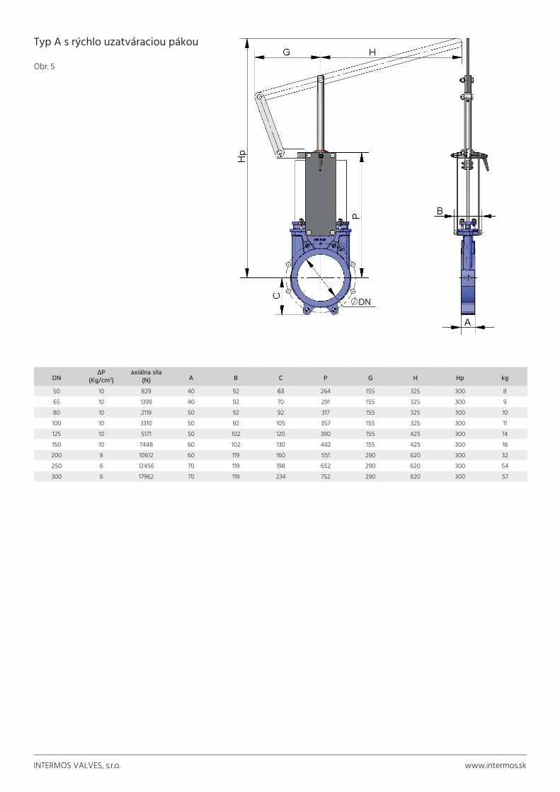
Typ A s rýchlo uzatváraciou pákou
Obr. 5
DN ΔP
(Kg/cm2)axiálna sila
(N) A B C P G H Hp kg
50 10 829 40 92 63 264 155 325 300 865 10 1399 40 92 70 291 155 325 300 980 10 2119 50 92 92 317 155 325 300 10100 10 3310 50 92 105 357 155 325 300 11125 10 5171 50 102 120 390 155 425 300 14150 10 7448 60 102 130 442 155 425 300 16200 8 10612 60 119 160 551 290 620 300 32250 6 12456 70 119 198 652 290 620 300 54300 6 17962 70 119 234 752 290 620 300 57
K N I F E - G A T E V A L V E S A S E R I E S
C.M.O. Amategui Aldea 142, 20400 Txarama‐Tolosa (SPAIN) TEC‐A.EN07
Tel. Nacional: 902.40.80.50 Fax: 902.40.80.51 / Tel. Internacional: 34.943.67.33.99 Fax: [email protected] http://www.cmo.esPage14
It is a fast actuator B = Max. width of the valve (without actuator) P = Max. height of the valve
(without actuator)
The actuator includes: ‐ Lever ‐ Rod ‐ Guide bearing ‐ External limiting switches to maintain the position.
Available: ND50 to ND300, other ND on request.
ND ΔP (Kg/cm2)
DRAW (Nw) A B C P G H Hp Weight
(kg.) 50 10 829 40 92 63 264 155 325 504 8 65 10 1399 40 92 70 291 155 325 526 9 80 10 2119 50 92 92 317 155 325 549 10 100 10 3310 50 92 105 357 155 325 605 11 125 10 5171 50 102 120 390 155 425 902 14 150 10 7448 60 102 130 442 155 425 956 16 200 8 10612 60 119 160 551 290 620 1027 32 250 6 12456 70 119 198 652 290 620 1416 54 300 6 17962 70 119 234 752 290 620 1525 57
LEVER
table 7
fig. 20 ND
fig. 20 DN

INTERMOS VALVES, s.r.o. www.intermos.sk
Typ A s reťazovým kolesom
Obr. 6
DN ΔP
(Kg/cm2)axiálna sila
(Nw) moment
(Nm) A B C D Hc ØVc kg
50 10 829 2 40 92 63 264 409 225 765 10 1399 3 40 92 70 291 436 225 880 10 2119 5 50 92 92 317 469 225 9100 10 3310 8 50 92 105 357 502 225 11125 10 5171 12 50 102 120 390 585 225 13150 10 7448 17 60 102 130 442 644 225 17200 8 10612 30 60 119 160 551 815 300 29250 6 12456 36 70 119 198 652 1016 300 40300 6 17962 51 70 119 234 752 1116 300 53350 5 20406 79 96 290 256 879 1336 402 93400 5 26707 104 100 290 292 985 1442 402 126450 3 20376 79 106 290 308 1071 1628 402 160500 3 25230 98 110 290 340 1183 1738 402 193600 3 36506 142 110 290 400 1389 2046 402 264700 2 33288 182* 110 320 453 1506 2406 402* 435800 2 43788 239* 110 320 503 1720 2790 402* 580900 2 56064 307* 110 320 583 1953 3130 402* 7401000 2 69269 379* 110 320 613 2137 3440 402* 9251200 2 100819 654* 150 340 728 2616 4050 402* 1350
* s prevodom a reťazovým kolesom
K N I F E - G A T E V A L V E S A S E R I E S
C.M.O. Amategui Aldea 142, 20400 Txarama‐Tolosa (SPAIN) TEC‐A.EN07
Tel. Nacional: 902.40.80.50 Fax: 902.40.80.51 / Tel. Internacional: 34.943.67.33.99 Fax: [email protected] http://www.cmo.esPage13
Widely used in raised installations with difficult access, the handwheel is fitted in vertical position.
B = Max. width of the valve (without actuator)
Options: ‐ Locking devices ‐ Extensions: stand, pipe, plates... ‐ Non‐rising stem ‐ DN higher than those give in the table
Including: ‐ Handwheel ‐ Stem ‐ Nut ‐ Hood Available: ND50 to ND1200, other ND on request.
From DN600 the actuator is with gears, see * in table.
ND ΔP (Kg/cm2)
DRAW (Nw)
TORQ.(Nm) A B C D Hc ØVc Weight
(kg.) 50 10 829 2 40 92 63 264 409 225 7 65 10 1399 3 40 92 70 291 436 225 8 80 10 2119 5 50 92 92 317 469 225 9 100 10 3310 8 50 92 105 357 502 225 11 125 10 5171 12 50 102 120 390 585 225 13 150 10 7448 17 60 102 130 442 644 225 17 200 8 10612 30 60 119 160 551 815 300 29 250 6 12456 36 70 119 198 652 1016 300 40 300 6 17962 51 70 119 234 752 1116 300 53 350 5 20406 79 96 290 256 879 1336 402 93 400 5 26707 104 100 290 292 985 1442 402 126 450 3 20376 79 106 290 308 1071 1628 402 160 500 3 25230 98 110 290 340 1183 1738 402 193 600 3 36506 142 110 290 400 1389 2046 402 264 700 2 33288 182* 110 320 453 1506 2406 402* 435 800 2 43788 239* 110 320 503 1720 2790 402* 580 900 2 56064 307* 110 320 583 1953 3130 402* 740 1000 2 69269 379* 110 320 613 2137 3440 402* 925 1200 2 100819 654* 150 340 728 2616 4050 402* 1350
CHAINWHEEL
fig. 19
table 6
NDDN

INTERMOS VALVES, s.r.o. www.intermos.sk
Typ A s 2-činným pneumatickým pohonom
Obr. 7
DN ΔP
(Kg/cm2)axiálna sila
(Nw) A B C Ø
valce Ø
piestnej tyče J S
(B.S.P.) Hn kg
50 10 829 40 92 63 80 20 96 1/4“ 415 765 10 1399 40 92 70 80 20 96 1/4“ 455 880 10 2119 50 92 92 80 20 96 1/4“ 498 9100 10 3310 50 92 105 100 20 115 1/4“ 565 12125 10 5171 50 102 120 125 25 138 1/4“ 636 18150 10 7448 60 102 130 125 25 138 1/4“ 717 22200 8 10612 60 119 160 160 30 175 1/4“ 874 37250 6 12456 70 119 198 200 30 218 3/8“ 1036 58300 6 17962 70 119 234 200 30 218 3/8“ 1182 72350 5 20406 96 290 256 250 40 270 3/8“ 1380 130400 5 26707 100 290 292 250 40 270 3/8“ 1530 155450 3 20376 106 290 308 300 45 382 1/2“ 1677 225500 3 25230 110 290 340 300 45 382 1/2“ 1839 257600 3 36506 110 290 400 300 45 382 1/2“ 2146 340700 2 33288 110 320 453 350 45 426 1/2“ 2481 556800 2 43788 110 320 503 350 45 426 1/2“ 2798 679900 2 56064 110 320 583 400 50 508 1/2“ 3167 8401000 * * 110 320 613 400 50 508 1/2“ 3451 10531100 * * 150 340 670 400 50 508 1/2“ 3792 12101200 * * 150 340 728 400 50 508 1/2“ 4135 1366
K N I F E - G A T E V A L V E S A S E R I E S
C.M.O. Amategui Aldea 142, 20400 Txarama‐Tolosa (SPAIN) TEC‐A.EN07
Tel. Nacional: 902.40.80.50 Fax: 902.40.80.51 / Tel. Internacional: 34.943.67.33.99 Fax: [email protected] http://www.cmo.esPage16
The air supply pressure to the pneumatic cylinder is a minimum of 6 Kg/cm² and a maximum of 10 Kg/cm², the air must be dry and lubricated.
10 Kg/cm2 is the maximum admissible air pressure. For air pressures below 6 Kg/cm2 please consult to C.M.O.
For ND50 to ND200 valves, the cylinder’s jacket and covers are made of aluminium, the rod of AISI304, the piston of rubber‐coated steel and the O‐ring seals are made of nitrile.
For valves larger than ND200 the covers are made of nodular cast iron or carbon steel.
On request, we can also supply the actuator made entirely of stainless steel, especially for installation in corrosive atmospheres.
B = Max. width of the valve (without actuator)
Available: ND50 to ND1200, other ND on request.
ND ΔP (Kg/cm2)
DRAW (Nw) A B C Ø
CYL.Ø
ROD J S (B.S.P.) Hn Weight
(kg.) 50 10 829 40 92 63 80 20 96 1/4" 415 7 65 10 1399 40 92 70 80 20 96 1/4" 455 8 80 10 2119 50 92 92 80 20 96 1/4" 498 9 100 10 3310 50 92 105 100 20 115 1/4" 565 12 125 10 5171 50 102 120 125 25 138 1/4" 636 18 150 10 7448 60 102 130 125 25 138 1/4" 717 22 200 8 10612 60 119 160 160 30 175 1/4" 874 37 250 6 12456 70 119 198 200 30 218 3/8" 1036 58 300 6 17962 70 119 234 200 30 218 3/8" 1182 72 350 5 20406 96 290 256 250 40 270 3/8" 1380 130 400 5 26707 100 290 292 250 40 270 3/8" 1530 155 450 3 20376 106 290 308 300 45 382 1/2" 1677 225 500 3 25230 110 290 340 300 45 382 1/2" 1839 257 600 3 36506 110 290 400 300 45 382 1/2" 2146 340 700 2 33288 110 320 453 350 45 426 1/2" 2481 556 800 2 43788 110 320 503 350 45 426 1/2" 2798 679 900 2 56064 110 320 583 400 50 508 1/2" 3167 840 1000 * * 110 320 613 400 50 508 1/2" 3451 1053 1100 * * 150 340 670 400 50 508 1/2" 3792 1210 1200 * * 150 340 728 400 50 508 1/2" 4135 1366
DOUBLE‐ACTING PNEUMATIC CYLINDER
* Consult
CYL.
NDfig. 22
table 9
Ø VALCE
DN

INTERMOS VALVES, s.r.o. www.intermos.sk
Typ A s 1-činným pneumatickým pohonom
Obr. 8
DN ΔP
(Kg/cm2)axiálna sila
(Nw) A B C Ø
valce Ø
piestnej tyče J S
(B.S.P.) Hn kg
50 10 829 40 92 63 125 25 138 1/4“ 781 1965 10 1399 40 92 70 125 25 138 1/4“ 806 2280 10 2119 50 92 92 125 25 138 1/4“ 833 23100 10 3310 50 92 105 125 25 138 1/4“ 873 24125 10 5171 50 102 120 160 30 175 1/4“ 909 35150 10 7448 60 102 130 160 30 175 1/4“ 960 36200 8 10612 60 119 160 200 30 218 3/8“ 1355 66250 6 12456 70 119 198 250 40 270 3/8“ 1844 130300 6 17962 70 119 234 250 40 270 3/8“ 2005 143
K N I F E - G A T E V A L V E S A S E R I E S
C.M.O. Amategui Aldea 142, 20400 Txarama‐Tolosa (SPAIN) TEC‐A.EN07
Tel. Nacional: 902.40.80.50 Fax: 902.40.80.51 / Tel. Internacional: 34.943.67.33.99 Fax: [email protected] http://www.cmo.esPage17
The air supply pressure to the pneumatic cylinder is a minimum of 6 Kg/cm² and a maximum of 10 Kg/cm², the air must be dry and lubricated.
10 Kg/cm2 is the maximum admissible air pressure. For air pressures below 6 Kg/cm2 please consult to C.M.O.
Available for opening or closing in case of failure (spring opening or closing).
The jacket is made of aluminium, the covers of nodular cast iron or carbon steel, the rod of AISI304, the piston of rubber‐coated steel, the O‐ring seals of nitrile and the spring is made of steel.
The actuator design is spring activated for valves with diameters up to ND300. For larger diameters the actuator contains a double‐acting cylinder and an air tank which stores the volume of air necessary to perform the last movement in the event of a fault.
B = Max. width of the valve (without actuator)
Available: ND50 to ND300, other ND on request.
ND ΔP (Kg/cm2)
DRAW (Nw) A B C Ø
CYL.Ø
ROD J S(B.S.P.) Hn Weight
(kg.) 50 10 829 40 92 63 125 25 138 1/4" 781 19 65 10 1399 40 92 70 125 25 138 1/4" 806 22 80 10 2119 50 92 92 125 25 138 1/4" 833 23 100 10 3310 50 92 105 125 25 138 1/4" 873 24 125 10 5171 50 102 120 160 30 175 1/4" 909 35 150 10 7448 60 102 130 160 30 175 1/4" 960 36 200 8 10612 60 119 160 200 30 218 3/8" 1355 66 250 6 12456 70 119 198 250 40 270 3/8" 1844 130 300 6 17962 70 119 234 250 40 270 3/8" 2005 143
SINGLE‐ACTING PNEUMATIC CYLINDER
table 10
fig. 23
CYL
ND
Ø VALCE
DN

ROZMERY PRE MONTÁŽ MEDZI PRÍRUBY
K N I F E - G A T E V A L V E S A S E R I E S
C.M.O. Amategui Aldea 142, 20400 Txarama‐Tolosa (SPAIN) TEC‐A.EN07
Tel. Nacional: 902.40.80.50 Fax: 902.40.80.51 / Tel. Internacional: 34.943.67.33.99 Fax: [email protected] http://www.cmo.esPage20
EN 1092‐2 PN10
ANSI B16, class 150
ND ΔP (Kg/cm2) ● O R
UNC Prof. ØK
2" 10 4 ‐ 5/8" 8 120,62 1/2" 10 4 ‐ 5/8" 8 139,7
" 10 4 ‐ 5/8" 9 152,44" 10 4 4 5/8" 9 190,55" 10 4 4 3/4" 9 215,96" 10 4 4 3/4" 10 241,38" 8 4 4 3/4" 10 298,410" 6 6 6 7/8" 12 361,912" 6 6 6 7/8" 12 431,814" 5 8 4 1" 21 476,26" 5 10 6 1" 21 539,718" 3 10 6 1⅛" 22 577,820" 3 14 6 1⅛" 22 63524" 3 14 6 1¼" 22 749,328" 2 20 8 1¼" 22 863,630" 2 20 8 1¼" 22 914,432" 2 18 10 1½" 22 977,936" 2 20 12 1½" 20 1085,940" 2 24 12 1½" 20 1200,2
ND ΔP (Kg/cm2) ● O Metric Prof ØK
50 10 4 ‐ M 16 8 12565 10 4 ‐ M 16 8 14580 10 4 4 M 16 9 160100 10 4 4 M 16 9 180125 10 4 4 M 16 9 210150 10 4 4 M 20 10 240200 8 4 4 M 20 10 295250 6 6 6 M 20 12 350300 6 6 6 M 20 12 400350 5 10 6 M 20 21 460400 5 10 6 M 24 21 515450 3 14 6 M 24 22 565500 3 14 6 M 24 22 620600 3 14 6 M 27 22 725700 2 16 8 M 27 22 840800 2 16 8 M 30 22 950900 2 20 8 M 30 20 10501000 2 20 8 M 33 20 11601100 2 20 12 M 33 20 12701200 2 20 12 M 36 22 13801300 2 20 12 M 36 26 14901400 2 24 12 M 39 26 15901500 2 24 12 M 39 35 17001600 2 28 12 M 45 40 18201700 2 30 14 M 45 40 19201800 2 30 14 M 45 40 20201900 2 32 16 M 45 45 21202000 2 32 16 M 45 45 2230
INFORMATION ON FLANGE DIMENSIONS
● BLIND TAPPED HOLES ○ THROUGH HOLE
fig. 26
table 13
table 14
fig. 27
Obr. 9DN ΔP
(Kg/cm2) M
závit P ØK
50 10 4 - M 16 8 12565 10 4 - M 16 8 14580 10 4 4 M 16 9 160100 10 4 4 M 16 9 180125 10 4 4 M 16 9 210150 10 4 4 M 20 10 240200 8 4 4 M 20 10 295250 6 6 6 M 20 12 350300 6 6 6 M 20 12 400350 5 10 6 M 20 21 460400 5 10 6 M 24 21 515450 3 14 6 M 24 22 565500 3 14 6 M 24 22 620600 3 14 6 M 27 22 725700 2 16 8 M 27 22 840800 2 16 8 M 30 22 950900 2 20 8 M 30 20 10501000 2 20 8 M 33 20 11601100 2 20 12 M 33 20 12701200 2 20 12 M 36 22 13801300 2 20 12 M 36 26 14901400 2 24 12 M 39 26 15901500 2 24 12 M 39 35 17001600 2 28 12 M 45 40 18201700 2 30 14 M 45 40 19201800 2 30 14 M 45 40 20201900 2 32 16 M 45 45 21202000 2 32 16 M 45 45 2230
nepriechodné otvory
priechodné otvory
K N I F E - G A T E V A L V E S A S E R I E S
C.M.O. Amategui Aldea 142, 20400 Txarama‐Tolosa (SPAIN) TEC‐A.EN07
Tel. Nacional: 902.40.80.50 Fax: 902.40.80.51 / Tel. Internacional: 34.943.67.33.99 Fax: [email protected] http://www.cmo.esPage20
EN 1092‐2 PN10
ANSI B16, class 150
ND ΔP (Kg/cm2) ● O R
UNC Prof. ØK
2" 10 4 ‐ 5/8" 8 120,62 1/2" 10 4 ‐ 5/8" 8 139,7
" 10 4 ‐ 5/8" 9 152,44" 10 4 4 5/8" 9 190,55" 10 4 4 3/4" 9 215,96" 10 4 4 3/4" 10 241,38" 8 4 4 3/4" 10 298,410" 6 6 6 7/8" 12 361,912" 6 6 6 7/8" 12 431,814" 5 8 4 1" 21 476,26" 5 10 6 1" 21 539,718" 3 10 6 1⅛" 22 577,820" 3 14 6 1⅛" 22 63524" 3 14 6 1¼" 22 749,328" 2 20 8 1¼" 22 863,630" 2 20 8 1¼" 22 914,432" 2 18 10 1½" 22 977,936" 2 20 12 1½" 20 1085,940" 2 24 12 1½" 20 1200,2
ND ΔP (Kg/cm2) ● O Metric Prof ØK
50 10 4 ‐ M 16 8 12565 10 4 ‐ M 16 8 14580 10 4 4 M 16 9 160100 10 4 4 M 16 9 180125 10 4 4 M 16 9 210150 10 4 4 M 20 10 240200 8 4 4 M 20 10 295250 6 6 6 M 20 12 350300 6 6 6 M 20 12 400350 5 10 6 M 20 21 460400 5 10 6 M 24 21 515450 3 14 6 M 24 22 565500 3 14 6 M 24 22 620600 3 14 6 M 27 22 725700 2 16 8 M 27 22 840800 2 16 8 M 30 22 950900 2 20 8 M 30 20 10501000 2 20 8 M 33 20 11601100 2 20 12 M 33 20 12701200 2 20 12 M 36 22 13801300 2 20 12 M 36 26 14901400 2 24 12 M 39 26 15901500 2 24 12 M 39 35 17001600 2 28 12 M 45 40 18201700 2 30 14 M 45 40 19201800 2 30 14 M 45 40 20201900 2 32 16 M 45 45 21202000 2 32 16 M 45 45 2230
INFORMATION ON FLANGE DIMENSIONS
● BLIND TAPPED HOLES ○ THROUGH HOLE
fig. 26
table 13
table 14
fig. 27
Údaje uvedené v katalógu sú informatívne a dodávateľ si vyhradzuje právo na technické zmeny.
INTERMOS VALVES, s.r.o. Moskovská 13, 811 08 Bratislava – Staré Mesto+421 910 933 338, [email protected]