november 10, 2009coms w41561 coms w4156: advanced software engineering prof. gail kaiser...
TRANSCRIPT

November 10, 2009 COMS W4156 1
COMS W4156: Advanced Software Engineering
Prof. Gail Kaiser
http://bank.cs.columbia.edu/classes/cs4156/

November 10, 2009 COMS W4156 2
Topics covered in this lecture
• UML overview (reprise)
• Structural modeling
• Implementation diagrams

November 10, 2009 COMS W4156 3
Unified Modeling Language

November 10, 2009 COMS W4156 4
Reprise: What is UML?
• UML = Unified Modeling Language • A standard language for specifying, visualizing,
constructing and documenting software artifacts• Standardized by Object Management Group (OMG)• Uses mostly graphical notations• Helps project teams communicate, explore potential
designs, and validate the requirements and architectural design of the software system

November 10, 2009 COMS W4156 5
Goals of UML• Provide users with a ready-to-use, expressive visual
modeling language so they can develop and exchange meaningful models
• Provide extensibility and specialization mechanisms to augment the core concepts
• Be independent of particular programming languages, design methodologies and development processes
• Encourage the growth of the tools market• Support higher-level development concepts such as
frameworks, components and patterns• Integrate “best practices”

November 10, 2009 COMS W4156 6
Our Focus: the LanguageUnified Modeling Language
• Language = syntax + semantics– Syntax = rules by which language elements
(e.g., words) are assembled into expressions (e.g., phrases, clauses)
– Semantics = rules by which syntactic expressions are assigned meanings

November 10, 2009 COMS W4156 7
• The basic building blocks (syntax) of UML are:– Model elements (classes, interfaces, components,
use cases)– Relationships (associations, generalization,
dependencies)– Diagrams (class diagrams, use case diagrams,
interaction diagrams)
• Simple building blocks are used to create large, complex structures
Building Blocks

November 10, 2009 COMS W4156 8
Types of UML Diagrams
• Each UML diagram is designed to let developers and customers view a software system from a different perspective and in varying degrees of abstraction– Use Case– Behavioral– Structural– Implementation

November 10, 2009 COMS W4156 9
Structural Modeling
• Used to model the “things” that make up the software system
• Model class structure and contents
• Emphasizes the structure of objects, including their classifiers, attributes, operations and relationships

November 10, 2009 COMS W4156 10
Structural Diagrams
• Show a graph of elements connected by relationships
• Kinds– Class diagram: classifier view– Object diagram: instance view
• Shows the static structures of the system (not dynamic or temporal)

November 10, 2009 COMS W4156 11
Class Diagrams

November 10, 2009 COMS W4156 12
Class Diagrams
• Shows how the different entities (people, things and data) relate to each other
• A class diagram can be used to display logical classes, not necessarily code classes, which are typically the kinds of things the business people in an organization talk about — music bands, CDs, radio play; or home mortgages, car loans, interest rates
• Use domain vocabulary

November 10, 2009 COMS W4156 13
Example Class Diagram

November 10, 2009 COMS W4156 14
Class Notation
• A class is depicted on the class diagram as a rectangle with three horizontal sections (“compartments”)
• The upper section shows the class's name
• The middle section contains the class's attributes, optionally with initial values
• The lower section contains the class's operations or behaviors (methods)
• May be abbreviated to show just name, or just name and attributes

November 10, 2009 COMS W4156 15
Class Example

November 10, 2009 COMS W4156 16
Class Diagram • Draw a generalization relationship using a line
with an arrowhead at the top pointing to the super class, where the arrowhead should a completed triangle
• Draw an association relationship using– A solid line if both classes are aware of each other– A line with an open arrowhead if the association is
known by only one of the classes (pointing to the class known by the other one, i.e., direction of potential navigation)

November 10, 2009 COMS W4156 17
Example Class Diagram
Generalization
One-wayassociation
Two-wayassociation

November 10, 2009 COMS W4156 18
Generalization Example

November 10, 2009 COMS W4156 19
Association Example

November 10, 2009 COMS W4156 20
Construct Description Syntax
class a description of a set of objects that share the same attributes, operations, methods, relationships and semantics.
interface a named set of operations that characterize the behavior of an element.
component a modular, replaceable and significant part of a system that packages implementation and exposes a set of interfaces.
node a run-time physical object that represents a computational resource.
constraint a semantic condition or restriction.
«in terface»
Core Elements
{constra in t}

November 10, 2009 COMS W4156 21
Construct Description Syntax
association a relationship between two or more classifiers that involves connections among their instances.
aggregation A special form of association that specifies a whole-part relationship between the aggregate (whole) and the component part.
generalization a taxonomic relationship between a more general and a more specific element.
dependency a relationship between two modeling elements, in which a change to one modeling element (the independent element) will affect the other modeling element (the dependent element).
realization a relationship between a specification and its implementation.
Core Relationships

November 10, 2009 COMS W4156 22
Implementation Classes

November 10, 2009 COMS W4156 23
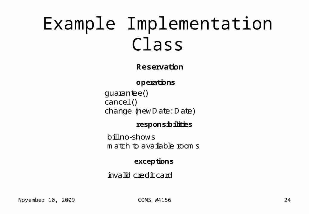
Implementation Class Diagrams
• Class diagrams can also be used to show implementation classes, which are the things that programmers typically deal with
• An implementation class diagram will probably show some of the same classes as the logical classes diagram
• The implementation class diagram won't be drawn with the same attributes, however, because it will most likely have references to things like Vectors and HashMaps
• May add compartments such as responsibilities and exceptions, even gist of method body
• May indicate attribute and operation visibility: public, private, protected, package
November 10, 2009 COMS W4156 24
Example Implementation Class
bill no-shows
Reservation
operations
guarantee()cancel ()change (newDate: Date)
responsibilities
match to available rooms
exceptions
invalid credit card

November 10, 2009 COMS W4156 25
Visibility Markers
• Signify who can access the information contained within a class
• Private visibility hides information from anything outside the class partition
• Public visibility allows all other classes to view the marked information
• Protected visibility allows child classes to access information they inherited from a parent class
• Package restricts visibility to the encompassing package

November 10, 2009 COMS W4156 26
Example Class Detail
Window
display ()
size: Areavisibility: Boolean
hide ()
Window
Window
+default-size: Rectangle#maximum-size: Rectangle
+create ()
+display ()
+size: Area = (100,100)#visibility: Boolean = true
+hide ()
-xptr: XWindow*
-attachXWindow(xwin:Xwindow*)
{abstract,author=Joe,status=tested}
+ = public- = private# = protected~ = package visibility

November 10, 2009 COMS W4156 27
Method Body Example
report ()
BurglarAlarm
isTripped: Boolean = false
PoliceStation
1 station
*
{ if isTrippedthen station.alert(self)}
alert (Alarm)

November 10, 2009 COMS W4156 28
Generalization
• Often represents inheritance at implementation class level
• Abstract class names given in italics
• Possibly multiple inheritance

November 10, 2009 COMS W4156 29
Generalization Example Equivalent Forms

November 10, 2009 COMS W4156 30
Generalization ExampleShape
SplineEllipsePolygon
Shape
SplineEllipsePolygon
Shared Target Style
Separate Target Style
. . .
. . .
November 10, 2009 COMS W4156 31
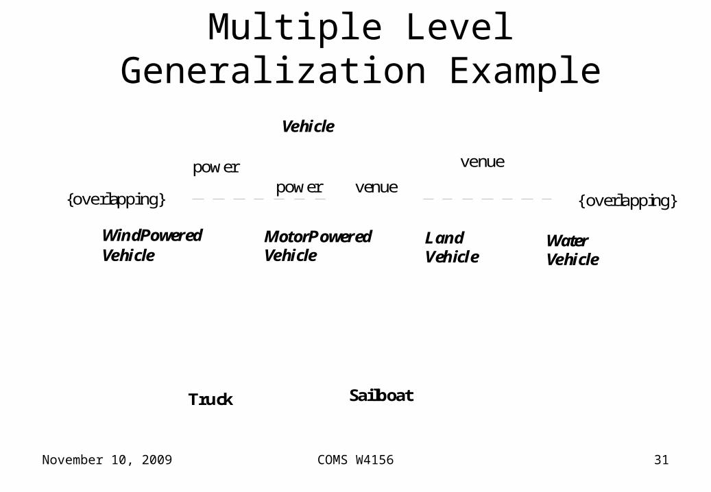
Multiple Level Generalization ExampleVehicle
WindPoweredVehicle
MotorPoweredVehicle
LandVehicle
WaterVehicle
venue
venuepowerpower
SailboatTruck
{overlapping} {overlapping}

November 10, 2009 COMS W4156 32
Associations
• Reflect connections, e.g., implemented as an instance variable in one or both classes
• Connector may include named roles at each end, cardinality, direction and constraints
• Self-associations permitted• May indicate choice (xor)• May be N-ary (not just binary)• Association classes allow an association connection
to have operations and attributes

November 10, 2009 COMS W4156 33
Association Example

November 10, 2009 COMS W4156 34
Association Class Example
November 10, 2009 COMS W4156 35
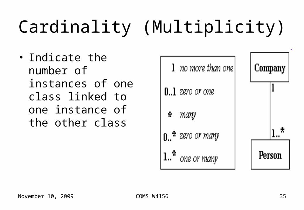
Cardinality (Multiplicity)
• Indicate the number of instances of one class linked to one instance of the other class

November 10, 2009 COMS W4156 36
Association Examples
Person
Manages
JobCompany
boss
worker
employeeemployer
0..1
Job
Account
Person
Corporation
{Xor}
salary

November 10, 2009 COMS W4156 37
PlayerTeam
Year
Record
goals forgoals againstwinslosses
goalkeeper
season
team
ties
Ternary Association Class Example

November 10, 2009 COMS W4156 38
Aggregations • Aggregations are a stronger form of association
between a whole and its parts• Drawn with a diamond next to the class representing
the target or whole (parent)• open vs. closed diamond indicates usage vs.
containment semantics• Containment may be indicated by composition rather
than relationship lines

November 10, 2009 COMS W4156 39
Aggregation Example

November 10, 2009 COMS W4156 40
Aggregation Example
Polygon PointContains
{ordered}
3..1
GraphicsBundle
colortexturedensity
1
1
-bundle
+vertex

November 10, 2009 COMS W4156 41
Composition ExampleWindow
scrollbar [2]: Slidertitle: Headerbody: Panel
Window
scrollbar title body
Header Panel
2 1 1
Slider
111
scrollbar:Slider
Window
2
title:Header1
body:Panel1

November 10, 2009 COMS W4156 42
Dependencies • Dependencies are a weaker form of association without
semantic knowledge• Often used early in the design process where it is known that
there is some kind of link between two elements, but it is too early to know exactly what the relationship is
• Later in the design process, dependencies may be replaced with a more specific type of connector
• Shown with a dashed line (e.g., from client to supplier)• <<label>> on line specifies kind (stereotype) of
dependency, e.g., <<instantiate>>, <<import>>, etc.

November 10, 2009 COMS W4156 43
Dependencies Example
«friend»ClassA ClassB
ClassC
«instantiate»
«call»
ClassD
operationZ()«friend»
ClassD ClassE
«refine»ClassC combines
two logical classes

November 10, 2009 COMS W4156 44
Dependencies Example
Controller
DiagramElements
DomainElements
GraphicsCore
«access»
«access»
«access»
«access»
«access»
November 10, 2009 COMS W4156 45
Interfaces• All interface operations are public and abstract, and all
interface attributes must be constants• By realizing an interface, classes are guaranteed to support a
required behavior, which allows the system to treat non-related elements in the same way – that is, through the common interface
• A class may implement multiple interfaces• An interface may be drawn in a similar style to a class, with
operations specified• Or may be drawn as a circle with no explicit operations
detailed (when drawn as a circle, realization links to the circle form of notation are drawn without target arrows)

November 10, 2009 COMS W4156 46
Interface Example

November 10, 2009 COMS W4156 47
Interface Realization Example

November 10, 2009 COMS W4156 48
Adapted from Fig. 23 [EJB 2.0].
+getOrderStatus+setOrderStatus+getLineItems+setLineItems+getCreditApproved+setCreditApproved
...
OrderBean{abstract}
LineItem{abstract}
Product
1
*
1
*
<<interface>>EntityBean
CreditCard{abstract}
Customer
PMOrder
PMLineItem
PMCreditCard
*
1
*
buyer
order
order
item
item
commodity
Interface Example

November 10, 2009 COMS W4156 49
Types and Implementation Classes Example
Set«type»
addElement(Object)removeElement(Object)testElement(Object):Boolean
* elements
Object«type»
HashTableSet«implementationClass»
addElement(Object)removeElement(Object)testElement(Object):Boolean
1 body
HashTable«implementationClass»
setTableSize(Integer)

November 10, 2009 COMS W4156 50
Object Diagrams

November 10, 2009 COMS W4156 51
Object Diagrams
• Refer to a specific instance of a class• Special case of a class diagram• Does not show operations but may show runtime
state• Object names are underlined and may optionally
show the name of the classifier from which the object is instantiated (or may be unnamed, but with the class specified)
• May compose multiple specific instances• May be drawn as glyphs

November 10, 2009 COMS W4156 52
Class vs. Object Diagram Example

November 10, 2009 COMS W4156 53
Run-time State Example

November 10, 2009 COMS W4156 54
More Object Examples
triangle: Polygon
center = (0,0)vertices = ( (0,0),(4,0) ,(4,3))borderC olor = blackfi llColor = white
triangle: Polygon
triangle
:Polygon
scheduler

November 10, 2009 COMS W4156 55
Composite Objects Example
horizontalBar:ScrollBar
verticalBar:ScrollBar
awindow : Window
surface:Pane
title:TitleBar
moves
moves

November 10, 2009 COMS W4156 56
Implementation Diagrams

November 10, 2009 COMS W4156 57
Implementation Diagrams
• Additional structural modeling (beyond classes, interfaces and objects)
• Show aspects of model implementation, including source code structure and run-time implementation structure
• Kinds– Component diagram– Deployment diagram

November 10, 2009 COMS W4156 58
Component Diagrams• Describes the software components that make up the
system• Not necessarily the same as the components of
component model frameworks• Provides a physical view of the system software• Shows the dependencies that the software has on the
other software components (e.g., software libraries) in the system
• A component is illustrated as a large rectangle with two smaller rectangles on the side, lollipops represent interfaces
• Dashed lines with arrows between components indicate dependencies

November 10, 2009 COMS W4156 59
Component Diagram Example

November 10, 2009 COMS W4156 60
Deployment Diagram
• Visualizes the physical architecture and the deployment of components on that hardware architecture
• Shows how a system will be physically deployed in the hardware environment, with distribution of components across the enterprise
• Its purpose is to show where the different components of the system will physically run and how they will communicate with each other

November 10, 2009 COMS W4156 61
Deployment Diagram Notation• A node represents either a virtual machine or a
physical machine node (e.g., a mainframe node)• To model a node, simply draw a three-dimensional
cube (or box) with the name of the node at the top of the cube
• Use the naming convention [instance name] : [instance type] (e.g., "w3reporting.myco.com : Application Server")
• Associations show communication connections between nodes (e.g., over a LAN)

November 10, 2009 COMS W4156 62
Deployment Diagram Example

November 10, 2009 COMS W4156 63
• UML is effective for modeling large, complex software systems
• The basics are simple to learn for most developers, but UML also provides advanced features for expert analysts, designers and architects
• It can specify systems independently from the programming language or implementation technology
• 10-20% of the constructs are used 80-90% of the time• Structural modeling specifies a skeleton for the structural
elements that supply the behavior (sequence, state, activity diagrams) and implement the use cases (use case diagrams)
• Implementation diagrams extend structural modeling to source code and run-time structure
Summary

November 10, 2009 COMS W4156 64
• http://www.uml.org/ — The official UML Web site• http://argouml.tigris.org/ — Information on Argo UML,
an open source UML modeling tool built in Java• http://uml.sourceforge.net/index.php — Information on
Umbrello UML Modeller, an open source UML modeling tool for KDE
• http://www-306.ibm.com/software/rational/uml/ - IBM’s UML resource center (IBM bought Rational in 2002)
Resources

November 10, 2009 COMS W4156 65
Final Notes

November 10, 2009 COMS W4156 66
Next Assignment
• Demos November 4th-12th

November 10, 2009 COMS W4156 67
Upcoming Deadlines
• Demos November 4th-12th
• First Iteration Final Report due November 13th
• Midterm Individual Assessment available by November 13th, due November 20th
• Second Iteration Plan due November 24th

November 10, 2009 COMS W4156 68
COMS W4156: Advanced Software Engineering
Prof. Gail Kaiser
http://bank.cs.columbia.edu/classes/cs4156/