novel ultra -wide band (uwb) antenna with dual band notch ... · n otch at frequency ( 9.2 ghz) is...
TRANSCRIPT

1
Novel Ultra-Wide Band (UWB)
Antenna with Dual Band Notch
Characteristics for Short Distance
Wireless Telecommunication
Applications
R.Kalyan1 Dr.K.T.V.Reddy2 Dr.K.Padma Priya3
1Research Scholar,
Department of ECE, JNTUA College of
Engineering, JNTUA, Anantapuramu, Andhra
Pradesh, India.
[email protected] 2Director, Pranveer Singh Institute of
Technology, Kanpur, Uttar Pradesh,
India. 3Professor, Department of ECE,
JNTUK College of Engineering,
JNTUK, Kakinada, Andhra Pradesh,
India.
Abstract
In this paper a novel, simple design, compact size, and low cost ultra- wide band (UWB) circular monopole micro strip patch antenna with dual band notch characteristics is presented. The first notch at WLAN (5.5GHz) frequency is achieved by the Double inverted Balloon shaped slot on the ground plane and the second notch at frequency (9.2GHz) is achieved due to a small slot on the patch. The proposed antenna is designed on FR4 substrate with size in mm. of Length 32, Width 52, and height 1.6. The antenna achieves the operational bandwidth from 3.1GHz to more than 10.6GHz which is
International Journal of Pure and Applied MathematicsVolume 114 No. 12 2017, 437-451ISSN: 1311-8080 (printed version); ISSN: 1314-3395 (on-line version)url: http://www.ijpam.euSpecial Issue ijpam.eu
437
2
used to increase the data transfer rate for short distance wireless telecommunication applications.
Key Words and Phrases: Ultra-Wide Band, Dual band notch, Double inverted Balloon shape, Circular monopole micro strip patch antenna.
1 Introduction
Ultra-Wide Band micro strip antennas are being more interesting,
attractive & promising wireless topic since Federal communication
commission (FCC) introduced the unlicensed 10-dB band of 7.5 GHz
(3.1 – 10.6 GHz) with an -41.5dBm/MHz effective isotropic radiated
power spectral density as UWB communications is utilized for short
distance wireless telecommunications in 2002 [1]. UWB technology
then became more advanced research topic in short distance wireless
telecommunication technology having the advantage of simplicity,
low spectral power density, less expensive, less power consumption,
less interference, and easy installation with an additional advantage of
faster data transfer rate as compared to other wireless technologies.
Due to this huge demand in the UWB communication system many
UWB antennas have been designed time to time. Beyond the
advantages the UWB antennas have many practical problems in
designing. In designing the antenna practical problems include return
loss, impedance matching, radiation characteristics, interference,
compact size, less manufacturing cost etc. Electromagnetic
interference problems are the serious problems in this communication
because of other existing narrow band services that are present in the
same UWB frequency bandwidth. In the recent years WLAN
(5.5GHz) frequency for many applications, has grown very widely
and is existing in the same UWB frequency band. Also if we are using
this UWB communication in satellite base stations, satellite frequency
(9.2GHz) is also present in the same UWB frequency range. An UWB
antenna with band filtering characteristics are required to mitigate the
potential interferences. It is very much desirable to design the
antennas without external filtering structures to minimize the footprint
of the antenna system, and the cost.
Printed circular monopole antenna designed on the substrate with a
double inverted balloon shaped slot on the ground plane achieves high
International Journal of Pure and Applied Mathematics Special Issue
438

3
band width for ultra-wide band. Many printed antennas are reported
time to time [2]-[5]. Since there are some narrow bands in between
this ultra-wide band which create the interference in UWB we need to
create band notched characteristics. So many Conventional techniques
are already reported to design ultra-wide band antenna with band
notched characteristics. There are papers which have been reported
like etching of different slots on the radiating patch, the ground plane
and on the feed line, using the electromagnetic band gap structures at
the feed line, using the resonators in between the patch and the ground
plane, by adding the additional filters on the patch, use of resonated
cells on the coplanar waveguide, use of tuning stubs, use of folded
stubs, meandering of ground plane and embedment of strip lines [6]-
[12]. Here we are introducing a novel UWB circular monopole micro
strip antenna with dual band notch characteristics which gives a good
results in terms of return loss, VSWR, Radiation pattern, directivity
and Gain. The paper starts with the designing of UWB antenna and
the design is extended to get the first notch and then second notch.
The design is carried out by the structural simulator of high frequency
structural simulator HFSS of ANSOFT Corporation. The results are
validated by using the parametric study. Parametric setup has been
carried out for the variation of the both notches. The details of the
antenna without notches and with notches is given in the following
sections.
2 Antenna Design
In the antenna design first we are investigating the ultra-wide band in
first section and in second section we are finding the notches.
A. UWB circular monopole antenna design
In designing of ultra-wide band antenna a slot on the ground plane
gives good coupling between the patch and the ground plane. So we
have taken a small rectangular slot on the ground plane and for this
slot we have added a circular slots to improve the resonance, the
coupling increases if we add the circle for the slot as well as the band
width is not up to the mark. So we have added another circular shaped
slot to increase the resonance. This cutting of slots increase the
resonance of the patch and ground plane and increase the band width.
International Journal of Pure and Applied Mathematics Special Issue
439
4
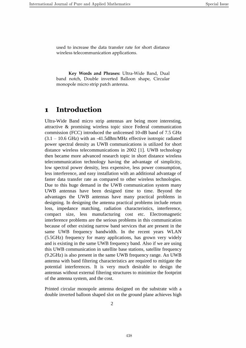
Fig. 1. Geometry of proposed UWB antenna with double inverted
balloon shaped slot on the ground plane and a small rectangular slot
on the radiating patch with band notch characteristics.
The antenna is having the overall dimensions of length 32mm and
width 57mm and height 1.6mm and the substrate used is FR4 epoxy
with the tangent 0.02, relative permittivity 4.4. All the dimensions are
listed in the table below
Variable Length in MM
L 32
W 57
L1 7.5
L2 4
L3 11
L4 5
L5 0.2
W1 3.2
W2 7
W3 3
Table 1. Variable values of the proposed UWB antenna
The design have been started with the single square slot on the ground
plane as shown in figure 2 the return loss for the different lengths is
shown in the figure 2 the variation in length is studied with the
parametric analysis.
The antenna proposed in figure 2 is having a small rectangular slot on
the ground plane which is having the length of S1l of 11mm. the
parametric analysis for the different s1l values have been studied here
in figure 3.
International Journal of Pure and Applied Mathematics Special Issue
440

5
Fig. 2. Antenna with small rectangular slot on the ground plane
The antenna shown in figure 2 is plotted in the figure 3 the parametric
setup is done for s1l for different lengths of y=10mm, y1=11mm,
y2=13mm, y4=14mm but the UWB is not achieved.
Fig. 3. S11 variation with frequency for different values of s1l with
small rectangular slot on the ground plane
To achieve the UWB the antenna should have the good resonance
between patch and ground plane and the variation of return loss with
S1l is shown in figure 3. There is no any variation in the band width,
so we have etched the two circular slots on the ground plane as shone
in figure3.
2 3 4 5 6 7 8 9 10 11 12-30
-25
-20
-15
-10
-5
0
frequency
s11
return loss vs freqency
y
y1
y2
y3
y4
International Journal of Pure and Applied Mathematics Special Issue
441
6
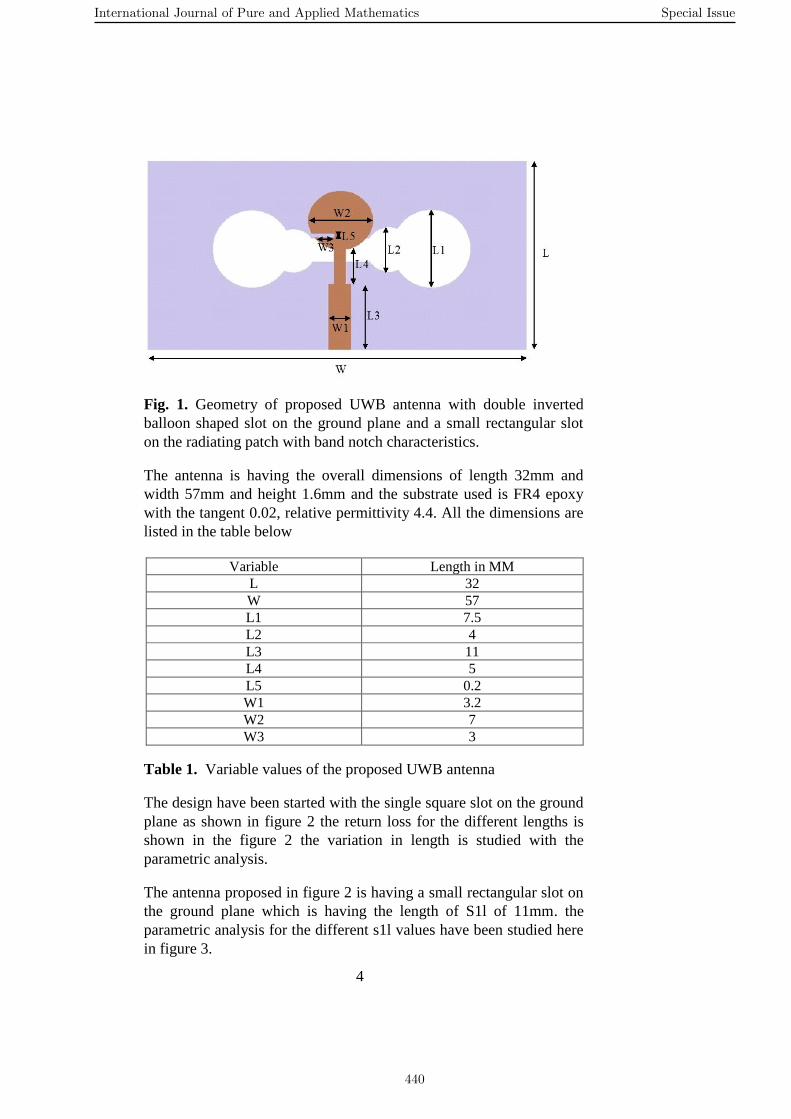
Fig. 4. Antenna with small rectangular slot attached with two circles
on the ground plane
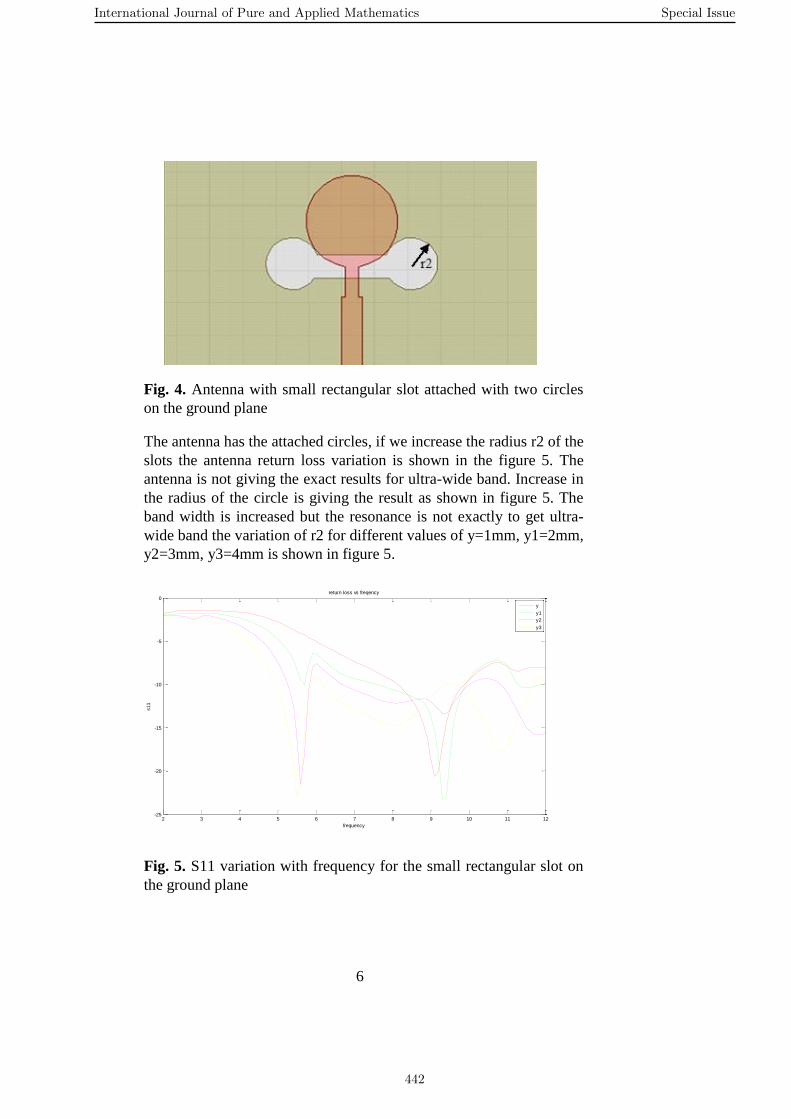
The antenna has the attached circles, if we increase the radius r2 of the
slots the antenna return loss variation is shown in the figure 5. The
antenna is not giving the exact results for ultra-wide band. Increase in
the radius of the circle is giving the result as shown in figure 5. The
band width is increased but the resonance is not exactly to get ultra-
wide band the variation of r2 for different values of y=1mm, y1=2mm,
y2=3mm, y3=4mm is shown in figure 5.
Fig. 5. S11 variation with frequency for the small rectangular slot on
the ground plane
2 3 4 5 6 7 8 9 10 11 12-25
-20
-15
-10
-5
0
frequency
s11
return loss vs freqency
y
y1
y2
y3
International Journal of Pure and Applied Mathematics Special Issue
442
7
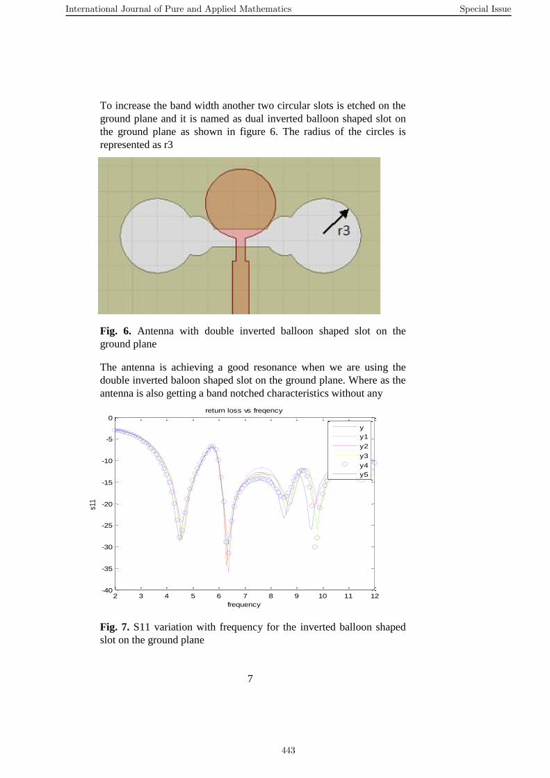
To increase the band width another two circular slots is etched on the
ground plane and it is named as dual inverted balloon shaped slot on
the ground plane as shown in figure 6. The radius of the circles is
represented as r3
Fig. 6. Antenna with double inverted balloon shaped slot on the
ground plane
The antenna is achieving a good resonance when we are using the
double inverted baloon shaped slot on the ground plane. Where as the
antenna is also getting a band notched characteristics without any
Fig. 7. S11 variation with frequency for the inverted balloon shaped
slot on the ground plane
2 3 4 5 6 7 8 9 10 11 12-40
-35
-30
-25
-20
-15
-10
-5
0
frequency
s11
return loss vs freqency
y
y1
y2
y3
y4
y5
International Journal of Pure and Applied Mathematics Special Issue
443
8
external filters and any other slots on the ground plane, this is novel
technique where we are achieing the notch as well as the UWB both
with this inverted baloon shaped slot. And the variation of different
values of r3 in terms of y=6mm, y1=6.2mm, y2=6.4mm, y3=6.6mm,
y4=6.8mm, y5=7mm is shown in figure 7. For different values of r3 in
terms of y shows that the y5 which is 7mm gives a good result of this
antenna to achieve ultra wide band and the notch at WLAN (5.5GHz).
B. UWB circular monopole antenna with band notched
characteristics
The band notched characteristics is achieved due to dual inverted
balloon shaped slot on the ground plane gives one notch at WLAN
(5.5GHz) frequency. And another slot etched on the radiating patch
near the feed line to get the notch at satellite frequency (8.7 GHz).
And the antenna is shown in the figure1.
3 Experimental Results
Antenna as shown in the figure1 gives good UWB and the notched
characteristics. Results and discussion is shown in this section
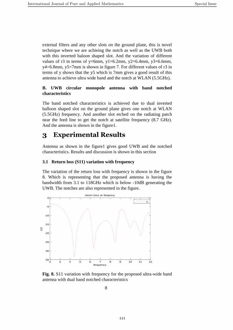
3.1 Return loss (S11) variation with frequency
The variation of the return loss with frequency is shown in the figure
8. Which is representing that the proposed antenna is having the
bandwidth from 3.1 to 118GHz which is below -10dB generating the
UWB. The notches are also represented in the figure.
Fig. 8. S11 variation with frequency for the proposed ultra-wide band
antenna with dual band notched characteristics
2 3 4 5 6 7 8 9 10 11 12-35
-30
-25
-20
-15
-10
-5
0
frequency
s11
return loss vs freqency
y
International Journal of Pure and Applied Mathematics Special Issue
444
9
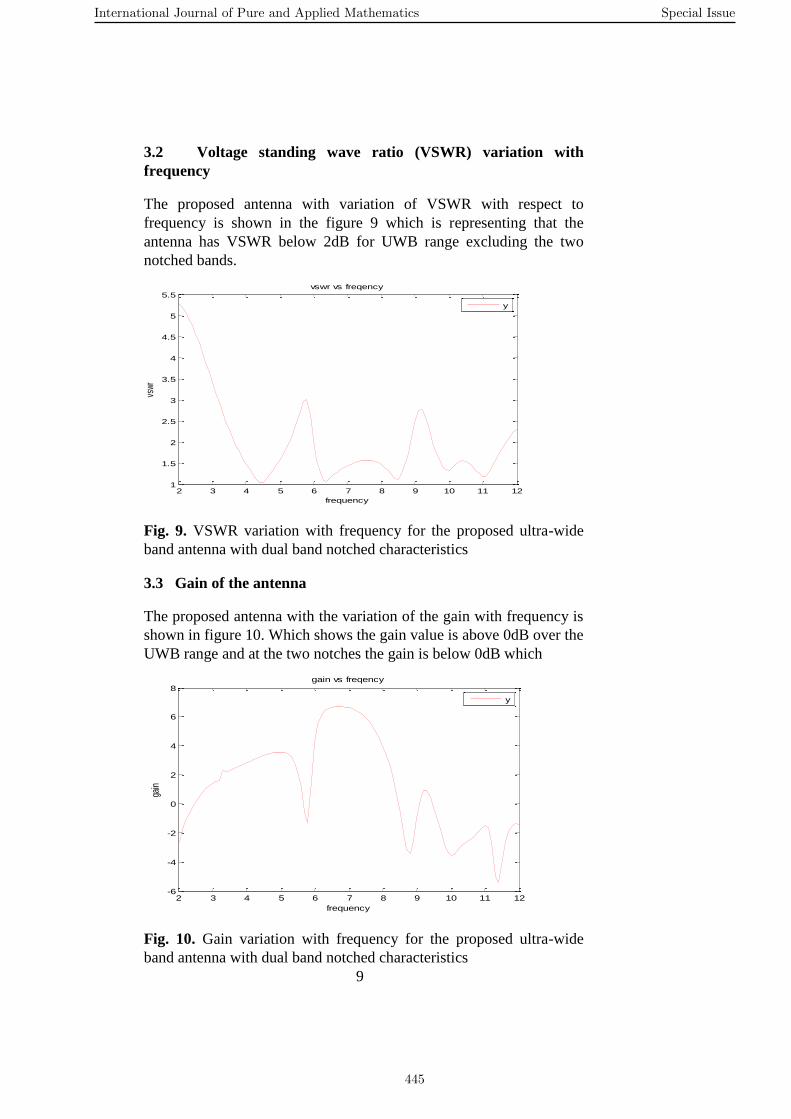
3.2 Voltage standing wave ratio (VSWR) variation with
frequency
The proposed antenna with variation of VSWR with respect to
frequency is shown in the figure 9 which is representing that the
antenna has VSWR below 2dB for UWB range excluding the two
notched bands.
Fig. 9. VSWR variation with frequency for the proposed ultra-wide
band antenna with dual band notched characteristics
3.3 Gain of the antenna
The proposed antenna with the variation of the gain with frequency is
shown in figure 10. Which shows the gain value is above 0dB over the
UWB range and at the two notches the gain is below 0dB which
Fig. 10. Gain variation with frequency for the proposed ultra-wide
band antenna with dual band notched characteristics
2 3 4 5 6 7 8 9 10 11 121
1.5
2
2.5
3
3.5
4
4.5
5
5.5
frequency
vsw
r
vswr vs freqency
y
2 3 4 5 6 7 8 9 10 11 12-6
-4
-2
0
2
4
6
8
frequency
gain
gain vs freqency
y
International Journal of Pure and Applied Mathematics Special Issue
445

10
represents that the antenna is rejecting the particular frequencies. And
the overall gain is approximately 3dB and the peak gain is at 6.6GHz
with 6.6dB.
3.4 Impedance
The proposed antenna is given with an impedance of 50 ohm. the
figure 11 represent the variation of impedance with frequency, which
is having the approximate value over UWB region and the maximum
impedance at the notched bands.
Fig. 11. Impedance vs frequency for the proposed ultra-wide band
antenna with dual band notched characteristics
3.5 Radiation pattern of the antenna
Fig. 12. Two dimensional radiation pattern of the proposed ultra-wide
band antenna with dual band notched characteristics
2 3 4 5 6 7 8 9 10 11 120
20
40
60
80
100
120
140
frequency
rez
impedence vs freqency
y
International Journal of Pure and Applied Mathematics Special Issue
446
11
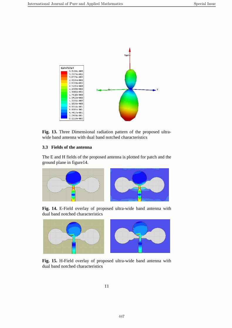
Fig. 13. Three Dimensional radiation pattern of the proposed ultra-
wide band antenna with dual band notched characteristics
3.3 Fields of the antenna
The E and H fields of the proposed antenna is plotted for patch and the
ground plane in figure14.
Fig. 14. E-Field overlay of proposed ultra-wide band antenna with
dual band notched characteristics
Fig. 15. H-Field overlay of proposed ultra-wide band antenna with
dual band notched characteristics
International Journal of Pure and Applied Mathematics Special Issue
447
12
4 Conclusion
A circular monopole ultra-wide band micro strip antenna with double
inverted balloon shaped patch on ground plane has been presented.
The antenna gives a good bandwidth of 3.1 to 11.8GHz. Which can be
used for ultra-wide band applications. A balloon shaped slot is etched
on the ground plane to get the good resonance between radiating patch
and ground plane. Also the notch is present due to the slot on the
ground plane. For another notch there is a small rectangular slot on the
patch. So this antenna achieves an ultra-wide band bandwidth and two
narrow band rejections. This antenna can be excellent for ultra-wide
band applications like satellite base stations, submarines and the high
data transfer applications in medical field.
References [1] Fedral Communication Commission, “First order and report:
Revision of part 15 of the Commision's rules regarding UWB
transmission systems,” April 22, 2002.
[2] N. Agrawall, G. Kumar, and K. Ray, “Wide-band planar
monopole antennas,”IEEE Trans. Antennas Propag., vol. 46, no. 2,
pp. 294–295, Feb. 1998.
[3] J. Clerk, J. Liang, C. C. Chiau, X. Chen, and C. G. Parini, “Study
of a printed circular disc monopole antenna for UWB systems,”
IEEE Trans. Antennas Propag., vol. 53, no. 11, pp. 3500–3504,
Nov. 2005.
[4] K. L. Wong, S. W. Su, and C. L. Tang, “Broadband
omnidirectional metal-plate monopole antenna,” IEEE Trans.
Antennas Propag., vol. 53, no. 1, pp. 581–583, Jan. 2005.
[5] M. J. Ammann and Z. N. Chen, “A wide-band shorted planar
monopole with bevel,” IEEE Trans. Antennas Propag., vol. 51, no.
4, pp. 901–903, Apr. 2003.
[6] Y. D. Dong,W. Hong, Z. Q. Kuai, and J. X. Chen, “Analysis of
planar ultra wide band antennas with on-ground slot band-notched
structures,” IEEE Trans. Antennas Propag., vol. 57, no. 7, pp.
1886–1893, Jul. 2009.
[7] W. X. Liu and Y.-Z. Yin, “Dual band-notched antenna with the
parasitic strip for UWB,” Prog. Electromagn. Res. Lett., vol. 25,
pp. 21–30, 2011.
International Journal of Pure and Applied Mathematics Special Issue
448
13
[8] M. Koohestani, N. Pires,A.K. Skrivervik, and A. A. Moreira,
“Band reject ultra-wideband monopole antenna using patch
loading,” Electron. Lett., vol. 48, no. 16, pp. 974–975, 2012.
[9] J.-Y. Kim, N. Kim, S. Lee, and B.-C. Oh, “Triple band-notched
UWB monopole antenna with two resonator structures,” Microw.
Opt. Technol. Lett., vol. 55, no. 1, pp. 4–6, 2013.
[10] D.-H. Lee, H.-Y. Yang, and Y.-K. Cho, “Tapered slot
antenna with band-notched function for ultra wide band radios,”
IEEE Antennas Wireless Propag. Lett., vol. 11, pp. 682–685,
2012.
[11] T. Li, H.-Q. Zhai, G.-H. Li, and C.-H. Liang, “Design of
compact UWB band-notched antenna by means of
electromagnetic-bandgap structures,” Electron. Lett., vol. 48, no.
11, pp. 608–609, 2012.
[12] S. Y. Suh, W. L. Stutzman, W. A. Davis, and A. E. Waltho,
“A UWB antenna with a stop-band notch in the 5-GHz WLAN
band,” in Proc. IEEE/ACES Int. Conf., 2005, pp. 203–207.
[13] M. Gopikrishna, D. D. Krishna, and C. K. Aanandan, “Band
notched semi-elliptic slot antenna for UWB systems,” in Proc.
Eur. Microw. Conf., 2008, pp. 889–892.
[14] Y. D. Dong, W. Hong, Z. Q. Kuai, C. Yu, Y. Zhang, J. Y.
Zhou, and J. X. Chen, “Development of ultrawideband antenna
with multiple band notched characteristics using half mode
substrate integrated waveguide cavity technology,” IEEE Trans.
Antennas Propag., vol. 56, no. 9, pp 2894–2902, Sep. 2008.5
[15] E. Pancera, D. Modotto, A. Locatelli, F. M. Pigozzo, and C.
D. Angelis, “Novel design of UWB antenna with band-notch
capability,” in Proc. Eur. Conf. Wireless Technol., 2007, pp. 48–
50.
[16] F. Yang and Y. Rahmat-Samii, “Microstrip antennas
integrated with electromagnetic band-gap (EBG) structures: A low
mutual coupling design for array applications,” IEEE Trans.
Antennas Propag., vol. 51, no. 10, pp. 2936–2946, Oct. 2003.
[17] L. Peng and C. L. Ruan, "UWB band-notched monopole
antenna design using electromagnetic-bandgap structure," IEEE
Trans. Microwave Theory and Technique, vol. 59, no. 4, pp. 1074-
1081, apr. 2011.
[18] M. Yazdi, N Komjani, "Design of a band-notched UWB
monopole antenna by means of an EBG structure," IEEE Trans.
Antennas Propag. letters, vol. 10, pp. 170–173, 2011.
[19] T. Li, H. Q. Zhai, G. H. Li, and C. H. Liang, " design of
compact UWB band-notched antenna by means of
electromagnetic-bandgap structures," Electronic Letters, vol. 48,
no. 11, may 2012.
International Journal of Pure and Applied Mathematics Special Issue
449

14
[20] F. Xu, Z. X. Wang, X. Chen, and X. A. Wang, '' Dual band-
notched UWB antenna based on spiral electromagnetic-bandgap
structure," PIER B, vol. 39, pp. 393-409, 2012.
[21] High Frequency structure Simulator (HFSS), Ansoft
[Online] available: http://www.ansoft.com.
International Journal of Pure and Applied Mathematics Special Issue
450

451

452