novel pwm method with low ripple current for position
TRANSCRIPT

726 Journal of Power Electronics, Vol. 11, No. 5, September 2011
JPE 11-5-13
Novel PWM Method with Low Ripple Current forPosition Control Applications of BLDC Motors
Hag-Wone Kim∗, Hee-Keun Shin∗, Hyung-Soo Mok∗∗, Yong-Kyun Lee∗∗, and Kwan-Yuhl Cho†
†∗ Dept. of Control and Instrumentation Eng., Chungju National University, Chungju, Korea∗∗ Dept. of Electrical Eng., Konkuk University, Seoul, Korea
Abstract
BLDC Motors are widely used in various speed control applications due to their ease of control and low cost. Generally, theunipolar PWM method is used for speed control applications. However, the unipolar PWM method has a current spike problemin the braking operation which can be a problem in speed reversal which generally happens in position control applications.However, the current spike problem can be solved by the conventional bipolar PWM method. Although the current spike problemcan be solved, the conventional bipolar PWM method has the problem of a large current ripple. In this paper, a novel bipolarPWM method is proposed to solve this problem. The current ripple and the current spike problems are analyzed in this paper forthe unipolar and bipolar PWM methods. At last, the merits of the proposed bipolar PWM method are proven by experiment.
Key Words: Bipolar PWM, Brushless DC motor (BLDC motor), PWM method, Unipolar PWM
I. INTRODUCTION
Recently, the brushless DC (BLDC) motor and the perma-nent magnet synchronous motor (PMSM) have been receivinga great deal of attention because of their inherent advantagesof high power density, high efficiency, a large torque to inertiaratio, high starting torque, free maintenance, and ease ofcontrol [1]. Generally, a BLDC motor has a trapezoidal electromotive force (EMF) waveform, so the current waveform ofa BLDC motor has a square waveform to reduce torqueripple [2]. Therefore, a BLDC motor controller requires alow resolution position sensor and only one current sensor.On the other hand, since a permanent magnet synchronousmotor (PMSM) has a sinusoidal EMF waveform, the currentwaveform of a PMSM must be sinusoidal. As a result, aPMSM requires an expensive high resolution position sensorsuch as an absolutely encoder and resolver. Therefore, a BLDCmotor is generally used for low-cost applications due to itsease of control, and its low cost position and current sensors[3].
On the other hand, a BLDC motor’s electrical attributeis similar to a DC motor, so a BLDC motor’s pulse widthmodulation (PWM) method is similar to the PWM methodof a DC Motor. The only difference is the commutation. Thecommutation of a BLDC motor is electrically achieved bya 3 phase inverter, while the commutation of a DC motor
Manuscript received Aug. 26, 2010; revised Jul. 26, 2011Recommended for publication by Associate Editor Kyeong-Hwa Kim.
† Corresponding Author: [email protected]: +82-43-841-5322, Fax: +82-43-841-5320, Chungju Nat’l Univ.∗Dept. of Control and Instrumentation Eng., Chungju National University,Korea∗∗Dept. of Electrical Eng., Konkuk University, Korea
is carried out by a mechanical brush and commutator. Therehave been several studies on PWM methods for BLDC motors[2], [4]–[7]. In the PWM control of a BLDC motor, generally,the unipolar PWM method is used as a DC motor uses theunipolar PWM method for the chopping control in which onlyone switch is On and Off controlled by PWM among theselected two switches, while the other switch is in the On-state continuously. In general, four unipolar PWM methodsare used for controlling a BLDC motor, and the unipolarPWM methods are distinguished by the selection of the PWMswitch among the 2 On-state switches [2], [4]–[7]. Most ofthe studies on PWM methods are related to commutationtorque ripple minimization under the freewheeling interval.On the other hand, there is an interesting report on a PWMmethod for electromechanical actuators [8]. In that paper, ithas been reported that there is a current spike problem inthe period of speed reversal of the unipolar PWM method.It has also been reported that this bipolar PWM method, inwhich the active selected two switches by commutation areon and off controlled by the PWM at the same time, cancontrol the motor current effectively during the period of speedreversal. However, an analysis of the current spike of theunipolar PWM method was not reported in that paper. Also,the reason why the bipolar PWM method does not have acurrent spike problem was not reported. However, although thecurrent spike problem has been solved by the bipolar PWM,the symptoms of a large current ripple can be made by thebipolar PWM. Therefore, the torque ripple and the acousticnoise are remarkably increased, and the motor efficiency isreduced by the increased motor core loss of the bipolar PWMmethod.

Novel PWM Method with Low Ripple Current for · · · 727
Fig. 1. Equivalent circuit of BLDC motor.
In this paper, the reason why the current spike problem ofunipolar PWM happens in the braking operation, in which thedirection of the motor speed command and the direction ofthe real speed are opposite, is analyzed. In addition, a novelbipolar PWM method is proposed so that the motor current canbe controlled in the braking operation and the current ripplein the motoring mode can be reduced as much as the currentof the unipolar PWM. To analyze the current spike problem,the unipolar PWM method is explained and a mathematicalmodel of the unipolar PWM is described in section 2. Insection 3, the proposed new bipolar PWM method is explained.In section 4, experimental results are shown for the unipolarPWM method, the conventional bipolar PWM method, andthe proposed bipolar PWM method. From the experimentalresults, the merits of small current ripples without the currentspike problem of the proposed bipolar PWM method areproven.
II. MATHEMATICAL MODEL OF PWM METHODS FORBLDC MOTOR
Generally, a BLDC Motor has 3 phase stator windings.These windings can be modeled as stator resistance, induc-tance, and electromotive force (EMF). An equivalent circuitof a BLDC motor is shown in Fig. 1 and the phase currentand EMF shapes for a BLDC motor are shown in Fig. 2. Asshown in Fig. 2, the EMF of a BLDC motor has a trapezoidalwaveform and the current has a rectangular waveform. In everymoment, 2 phases of the motor are active phases which meansthat the gate drive signals are applied to these phases, and theother phase is an inactive phase which means that the gatedrive signal is not applied to this phase. The freewheelingcurrent by electrical commutation appears for this inactivephase after the turn-off commutation.
A. Mathematical model of unipolar PWM
To control of the voltage of the active phases, a PWMsignal is applied to a BLDC motor. In general, unipolar PWMmethods are used for the motoring operation of a BLDC motor[5], [6]. Unipolar PWM means that one switch of the activephase is in the PWM mode, while the other switch of the otheractive phase is turned on continuously. Generally there are 4types of PWM modes as shown in Fig. 3 [6]. In general, thecurrent dynamics of a commutation period can be changed bythe selection of PWM methods [5], [6].
In Fig. 4, the switching states for sector 1 are shown for thePWM on and off periods, respectively. In this figure, sector 1
Fig. 2. EMF and Phase Current of BLDC motor of motoring.
(a) H PWM-L On. (b) H On-L PWM.
(c) PWM-On. (d) On-PWM.
Fig. 3. Unipolar PWM patterns for BLDC motor operation[5], [6].
(a) PWM on state. (b) PWM off state.
Fig. 4. Switching states of motoring operation for PWM On and off cases onsector 1.
Fig. 5. Implementation for Unipolar PWM using Carrier Comparison.
728 Journal of Power Electronics, Vol. 11, No. 5, September 2011
means that the A+ and B- switches are the active switches ofthe active phases, as can be shown in Fig. 2. In the case of Fig.4, it is assumed that the A+ switch is turned on continuouslyand that the B- switch is in the PWM mode. Therefore, theB- switch is in the off state during the PWM off period. Theimplementation of the unipolar PWM method using the carriercomparison method is shown in Fig. 5. In this method, thePWM command is compared with the PWM carrier signal, andthe switching function S1 of the A+ switch and the switchingfunction S6 of the B- switch are determined. Since the A+switch is in the on state continuously, the positive line to linevoltage, vab, can be applied to the motor for any value of thePWM command.
The current dynamics of unipolar PWM can be calculatedfrom the equivalent circuit of Fig. 1. In the operation shown inFig. 4, if it is assumed that the current of the inactive C phaseis zero after electrical commutation, then the voltage equationcan be written as:
[Vdc
(1−S6)Vdc
]=
[R 00 R
][iaib
]
+
[L 00 L
]ddt
[iaib
]+
[eaeb
]+
[vnvn
].
(1)
In this equation, S6 is the switching function for the B-switch. S6 = 1 means that the B- switch is in the on-stateand the B+ switch is in the off-state. S6 = 0 means that the B-switch is in the off-state and the B+ switch is in the on-state bythe freewheeling diode. In this equation, the saturation voltageof switch is assumed to be zero.
In sector 1 of the motoring mode of the BLDC motor, whichis shown in Fig. 2, the phase currents and the EMF can beexpressed as:
ia ≥ 0,ea ≥ 0, ib ≤ 0,eb ≤ 0. (2)
The phase currents in this sector can be written as:
ia + ib = 0, ic = 0. (3)
The current dynamics of the A phase can be calculated fromequation (1) by subtraction of the second row from the firstrow and ib =−ia. The current dynamics can be expressed as:
S6Vdc = 2Ria +2Ldiadt
+ ea − eb. (4)
In sector 1, the EMF is constant as can be seen in Fig. 2. Asa result, ea = E, eb =−E. Therefore, the current dynamics ofthe PWM On period and the PWM Off period can be writtenas follows:
Ldiadt
=Vdc
2−Ria −E (5)
Ldiadt
=−Ria −E. (6)
In the PWM On period, the a phase current is increasedbecause right side of equation (5) is positive. In the PWMoff period, the a phase current is decreased because rightside of equation (6) is negative. Therefore, the current canbe controlled by the unipolar PWM method in the motoringoperation.
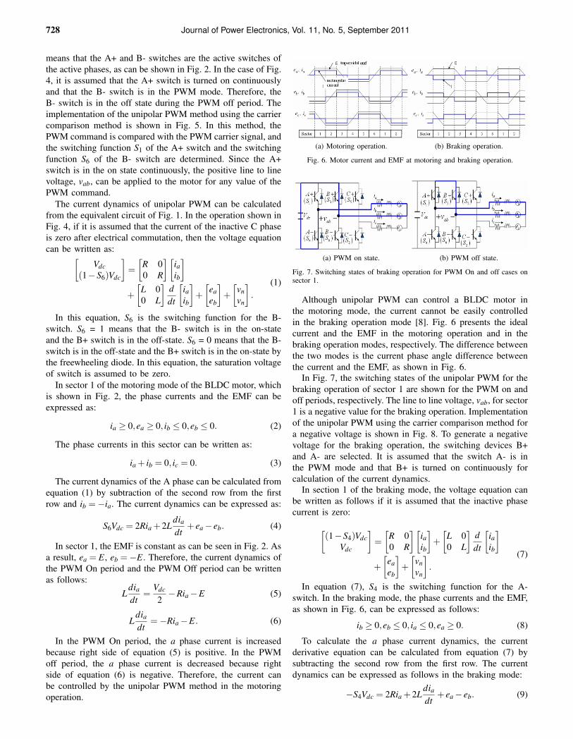
(a) Motoring operation. (b) Braking operation.
Fig. 6. Motor current and EMF at motoring and braking operation.
(a) PWM on state. (b) PWM off state.
Fig. 7. Switching states of braking operation for PWM On and off cases onsector 1.
Although unipolar PWM can control a BLDC motor inthe motoring mode, the current cannot be easily controlledin the braking operation mode [8]. Fig. 6 presents the idealcurrent and the EMF in the motoring operation and in thebraking operation modes, respectively. The difference betweenthe two modes is the current phase angle difference betweenthe current and the EMF, as shown in Fig. 6.
In Fig. 7, the switching states of the unipolar PWM for thebraking operation of sector 1 are shown for the PWM on andoff periods, respectively. The line to line voltage, vab, for sector1 is a negative value for the braking operation. Implementationof the unipolar PWM using the carrier comparison method fora negative voltage is shown in Fig. 8. To generate a negativevoltage for the braking operation, the switching devices B+and A- are selected. It is assumed that the switch A- is inthe PWM mode and that B+ is turned on continuously forcalculation of the current dynamics.
In section 1 of the braking mode, the voltage equation canbe written as follows if it is assumed that the inactive phasecurrent is zero:
[(1−S4)Vdc
Vdc
]=
[R 00 R
][iaib
]+
[L 00 L
]ddt
[iaib
]
+
[eaeb
]+
[vnvn
].
(7)
In equation (7), S4 is the switching function for the A-switch. In the braking mode, the phase currents and the EMF,as shown in Fig. 6, can be expressed as follows:
ib ≥ 0,eb ≤ 0, ia ≤ 0,ea ≥ 0. (8)
To calculate the a phase current dynamics, the currentderivative equation can be calculated from equation (7) bysubtracting the second row from the first row. The currentdynamics can be expressed as follows in the braking mode:
−S4Vdc = 2Ria +2Ldiadt
+ ea − eb. (9)

Novel PWM Method with Low Ripple Current for · · · 729
Fig. 8. Implementation for unipolar PWM for braking operation.
(a) –PWM. (b) +PWM.
Fig. 9. Switching states of braking operation. for bipolar PWM On sector 1.
Because ea = E, eb =−E in sector 1, the current dynamicsof the PWM on period and off period can be written as follows:
Ldiadt
=−Vdc
2−Ria −E (10)
Ldiadt
=−Ria −E, (11)
where S4 = 1 in the PWM on period and S4 = 0 in thePWM off period. Since right side of equation (10) is a largenegative value and the phase a current is also negative, theabsolute value of the phase a current is increased to a largenegative value rapidly in the PWM on period. Furthermore, inthe PWM Off period the absolute value of the phase absolutevalue of the a phase current is also increased to a negativevalue because the right side of equation (11) is negative.Therefore, the current cannot be controlled by the unipolarPWM method in the braking operation and can cause a currentspike. This current spike is not good for the system reliability[8]. To control the current, the PWM mode must be changedfrom the braking mode (in which the current dynamics areshown in equation (10) and (11)) to the motoring mode (inwhich the current dynamics are shown in equation (5) and(6)) in a very short period. However, this method complicatesthe implementation of the PWM method. To overcome thisproblem, the bipolar PWM method has been proposed [8].
B. Mathematical model of bipolar PWM
In bipolar PWM operation, the two active switches aresimultaneously on and off. In the braking operation of bipolarPWM, the switching states of sector 1 are represented in Fig.9 and the voltage equations are written as follows, if it isassumed that the inactive phase current is zero:
Fig. 10. Implementation for bipolar PWM using carrier comparison.
[(1−S4)Vdc
S3Vdc
]=
[R 00 R
][iaib
]+
[L 00 L
]ddt
[iaib
]
+
[eaeb
]+
[vnvn
].
(12)
In Fig. 10, the implementation of the bipolar PWM methodusing the carrier comparison method is shown. When thePWM command is less than the carrier wave, the PWM statebecomes the –PWM mode and the switching functions are S3 =S4 = 1. In this situation, the line to line voltage, vab, becomes−Vdc. When the PWM command is larger than the carrierwave, the PWM state becomes the +PWM mode and theswitching functions are S1 = S6 = 1. In this situation, the lineto line voltage, vab, becomes Vdc. When the PWM commandis larger than zero, the average line to line voltage in thePWM period, < vab >, is positive which means the motoringmode. If the PWM command is less than zero, the averageline to line voltage in the PWM period, <vab>, becomes anegative value which means the braking mode. Unlike unipolarPWM, the bipolar PWM method can easily produce a negativevoltage or a positive voltage without a change of the selectiveswitching device. Therefore, this PWM method is proposedfor the position control of a BLDC motor as an actuator inwhich the direction of the speed command can be changedfrom positive to negative or vice versa [8].
The current dynamics in the braking mode in sector 1 canbe expressed as:
(1−S3 −S4)Vdc = 2Ria +2Ldiadt
+ ea − eb. (13)
Because ea = E, eb =−E in sector 1, the current dynamicsof the PWM on period and the PWM off period can berepresented as follows:
Ldiadt
=−Vdc
2−Ria −E (14)
Ldiadt
=Vdc
2−Ria −E. (15)
The current dynamics of the -PWM period are same as thoseof the PWM On period of the braking control by the unipolarPWM in equation (10). However, the current dynamics ofthe +PWM period differ from equation (11), which is thePWM off period of the braking control. The right side ofequation (15) is positive and the A phase current is negative,so that the absolute value of the current during the + PWM
730 Journal of Power Electronics, Vol. 11, No. 5, September 2011
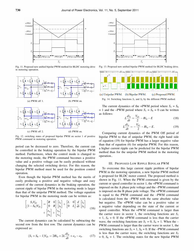
Fig. 11. Proposed new unified bipolar PWM method for BLDC motoring drivein motoring operation.
(a) PWM off 1. (b) PWM on.
(c) PWM off 2. (d) PWM on.
Fig. 12. switching states of proposed bipolar PWM on sector 1 of positivePWM command in motoring operation.
period can be decreased to zero. Therefore, the current canbe controlled in the braking operation by the bipolar PWMmethod. Furthermore, when the control mode is changed tothe motoring mode, the PWM command becomes a positivevalue and a positive voltage can be easily produced withoutchanging the selected switching device. For this reason, thebipolar PWM method must be used for the position controloperation.
Even though the bipolar PWM method has the merits ofeasily producing a positive and negative voltage and easycontrol of the current dynamics in the braking operation, thecurrent ripple of bipolar PWM in the motoring mode is largerthan that of the unipolar PWM method. The voltage equationfor bipolar PWM in the motoring mode can be written as:
[S1Vdc
(1−S6)Vdc
]=
[R 00 R
][iaib
]+
[L 00 L
]ddt
[iaib
]
+
[eaeb
]+
[vnvn
].
(16)
The current dynamics can be calculated by subtracting thesecond row from the first row. The current dynamics can beexpressed as:
(S1 +S6 −1)Vdc = 2Ria +2Ldiadt
+ ea − eb. (17)
Fig. 13. Proposed new unified bipolar PWM method for BLDC braking drive.
Fig. 14. Switching functions S1 and S4 by the different PWM method.
The current dynamics of the +PWM period where S1 = S6= 1 and the –PWM period where S1 = S6 = 0 can be writtenas follows:
Ldiadt
=Vdc
2−Ria −E (18)
Ldiadt
=−Vdc
2−Ria −E. (19)
Comparing current dynamics of the PWM Off period ofbipolar PWM to that of unipolar PWM, the right hand sideof equation (19) for bipolar PWM has a larger negative valuethan that of equation (6) for unipolar PWM. For this reason,a higher current ripple can be predicted for the bipolar PWMmethod than for the unipolar PWM method in the motoringoperation..
III. PROPOSED LOW RIPPLE BIPOLAR PWMTo overcome this large current ripple problem of bipolar
PWM in the motoring operation, a new bipolar PWM methodis proposed for BLDC motor control. The proposed method isshown in Fig. 11. When the PWM command is given by thecurrent or speed controller in sector 1, the +PWM command isimposed on the A phase pole voltage and the –PWM commandis imposed on the B phase pole voltage. The +PWM commandis equal to the PWM command and the –PWM commandis calculated from the –PWM with the same absolute valuebut negative. The +PWM value can be a positive value ora negative value depending on the state of the current orspeed controller. When the +PWM command is larger thanthe carrier wave in sector 1, the switching functions are S1= 1, S4 = 0. If the +PWM command is less than the carrierwave, the switching functions are S1 = 0, S4 = 1. When the –PWM command is larger than the carrier wave in sector 1, theswitching functions are S3 = 1, S6 = 0. If the –PWM commandis less than the carrier wave, the switching functions are S3= 0, S6 = 1. The switching states for the new bipolar PWM

Novel PWM Method with Low Ripple Current for · · · 731
Fig. 15. Enlarged switching functions S1 and S4 by the different PWM method.
(a) Unipolar PWM. (b) Bipolar PWM. (c) Proposed PWM.
Fig. 16. Current waveform comparison by PWM methods by simulation.
method when the PWM command is positive are shown inFig. 12.
The voltage equation for the proposed bipolar PWM can bewritten as:
[S1VdcS3Vdc
]=
[R 00 R
][iaib
]+
[L 00 L
]ddt
[iaib
]
+
[eaeb
]+
[vnvn
].
(20)
The current dynamics can be calculated by subtraction thesecond row from the first row. The current dynamics can beexpressed as:
(S1 −S3)Vdc = 2Ria +2Ldiadt
+ ea − eb. (21)
In the PWM on mode of sector 1 of Fig. 12, S1 = 1, S3 =0. Therefore, the current dynamics can be written as:
Ldiadt
=Vdc
2−Ria −E. (22)
During the PWM off 1 mode, S1 = 0, S3 = 0, and during thePWM off 2 mode, S1 = 1, S3 = 1. In both cases, the currentdynamics can be written as:
Ldiadt
=−Ria −E. (23)
Although, both switches carry out the PWM operation ofthe proposed PWM method, the current dynamics of equations(22) and (23) are equal to equations (10) and (11) which arethe current dynamics of the unipolar PWM method. The onlydifference with the unipolar PWM is that the PWM On eventand the PWM Off event happen twice in one PWM frequency,TS. Therefore, the effective switching period becomes doubledin the proposed method.
When the a phase PWM command is negative, the PWMoperation is as shown in Fig. 13. Since the a phase PWMcommand is a negative value, the BLDC motor operation modeis the braking mode. As can be seen in Fig. 13, the switchingfunction of the PWM On mode is S1 = 0, S3 = 1. Therefore,the current dynamics can be written from (21) as follows:
Ldiadt
=−Vdc
2−Ria −E (24)
TABLE ISPECIFICATIONS OF BLDC MOTOR
Parameters ValueNumber of Poles
Stator resistance @ 70CInductance
Back EMF constant
60.023Ω68µH
0.0109Vsec
During the PWM Off mode 1, S1 = 0, S3 = 0, and duringthe PWM Off mode 2, S1 = 1, S3 = 1. As a result, the currentdynamics can be written as:
Ldiadt
=−Ria −E. (25)
Therefore, the current cannot be controlled by the proposedbipolar PWM method in the braking operation mode only.However, the current can be controlled by the combined brak-ing and motoring operations, because a positive and negativevoltage can be easily produced by the proposed method. Whenthe current error between the current command and the realcurrent becomes a negative value, the current controller for theBLDC motor produces a positive voltage command. When thecurrent error becomes a positive value, the current controllerproduces a negative voltage command. In this application, aproportional controller must be used instead of a proportional-integral (PI) current controller.
IV. SIMULATION AND EXPERIMENTAL RESULTS
To verify the merits of the proposed bipolar PWM method,simulations and experiments for the three different PWMmethods are carried out. The PWM methods compared are theunipolar PWM, the bipolar PWM, and the proposed bipolarPWM. Fig. 14 shows the switching functions of the comparedPWM methods. Figure (a) in Fig. 14 shows the switchingfunction for S1 and S4 of the upper switch PWM in Fig.14. In this figure, the switching function S1 for A+ is in thePWM mode, but the switching function S4 is continuously onwhen the switch is selected by commutation logic. The figures(b) and (c) in Fig. 14 show the switching functions of thebipolar PWM and the proposed bipolar PWM, respectively.The switching functions S1 and S4 are both in the PWMmode, simultaneously. In Fig. 15, the switching function ofA+, S1, and the switching function of B+, S3, by the variousPWM methods are shown, respectively. As can be seen fromFig. 15, the switching function of S3 of the unipolar PWMis continuously in the off state regardless of the state of theswitching function of S1. The switching function of S3 ofthe conventional bipolar PWM is a logical inverting of S1including dead time because S4 is equal to S1. However, theswitching function S3 becomes either a high or low value bythe PWM command and the period of the high state is equalto the period of the low state of the switching function of S1,as can be seen in Fig. 11.
The current ripple is compared depending on the PWMmode by simulations and experiments. For these simulationsand experiments, the parameters of the BLDC motor used arelisted in Table I.
Fig. 16 shows the simulation current waveforms of theBLDC motor with the different PWM methods. As can beseen in this figure, the current ripple of the conventional PWM

732 Journal of Power Electronics, Vol. 11, No. 5, September 2011
(a) Unipolar PWM. (b) Bipolar PWM.
Fig. 17. Current ripple comparison between the unipolar and bipolar PWMin motoring operation.
(a) Bipolar PWM. (b) Proposed PWM.
Fig. 18. Current ripple comparison between the bipolar PWM in motoringoperation.
method is larger than that that of the unipolar PWM method.However, the proposed bipolar PWM method has low ripples,as much as compared with the conventional bipolar PWMmethod.
Fig. 17 shows the current of the BLDC motor for each ofthe different PWM methods. The left side figure shows thecurrent waveform of the unipolar PWM and the right sidefigure shows the current waveform of the conventional bipolarPWM in the motoring operation. As can be seen in this figure,the current ripple of the unipolar PWM method is smaller thanthat of the bipolar PWM method.
To compare the current ripples of the conventional bipolarand the propose bipolar PWM methods, Fig. 18 shows thecurrent ripple of the BLDC motor for the bipolar PWM andthe proposed bipolar PWM methods. The left side figure showsthe current waveform of the conventional bipolar PWM and theright side figure shows the current waveform of the proposedbipolar PWM. In this figure, it can be seen that the proposedmethod has a very small current ripple. Generally, acousticnoise is proportional to the current ripple. Therefore, acousticnoise can be reduced by the proposed PWM method. Also,the motor eddy current and hysteresis losses can be reducedby the proposed PWM method.
To compare the performance of the speed reversal, the speedreference and the current waveforms are shown in Fig. 19. Theunipolar PWM is used in Fig. 19(a), the conventional bipolarPWM is used in Fig. 19(b), and the proposed bipolar PWMis used in Fig. 19(c). All of the experimental waveforms aresaved in following steps. In the first step, the BLDC motor isoperated at 600rpm in the forward direction. At that time, thespeed reference is also 600rpm in the forward direction and themotor is operated in the motoring mode. In the next step, thespeed reference is changed to 600 rpm in the reverse direction.In this period, the direction of the motor speed reference and
(a) Unipolar PWM.
(b) Bipolar PWM.
(c) Proposed PWM.
Fig. 19. Current waveform comparison of the time of speed reversal.
the direction of the real speed are opposite. For this reason, themotor operation mode is the braking operation. After the motorspeed becomes zero, the directions of the speed referenceand the real speed are the same. Therefore, the operatingmode of the BLDC motor becomes the motoring mode. Inthis experiment, a current controller is used and the maximumcurrent is limited to 7A. A PI speed controller is used. Sincea PI speed controller is used, the current command is a smallvalue at the moment the speed reference is changed. However,the current command is increased by the integral action of thePI speed controller.
In the unipolar PWM method, the current is regulated bythe current controller in the motoring mode, as can be seen inFig. 19(a). However, the current ripple is very high and thecurrent can not be regulated in the braking mode, because thecurrent is larger than 7A in some instants. In the conventionalbipolar PWM method, the current seems to be controlled inthe braking mode, as can be seen in Fig. 19(b). However,the current is largely changed in every moment, because thevoltage applied to the inductance is largely changed by thePWM action as is known from equation (18) and (19). In theproposed PWM method, the current ripples of the motoring

Novel PWM Method with Low Ripple Current for · · · 733
mode and the braking mode are both small and the currentis also well controlled in the motoring mode and the brakingmode as can be seen in Fig. 19 (c).
V. CONCLUSIONS
Generally, BLDC motors are used for speed control applica-tions. In these applications the unipolar PWM method is used.However, in the application of the direction of a speed change,the unipolar PWM method cannot be applied. In this casethe bipolar PWM method must be applied. In this paper, thecurrent dynamics of the motoring mode and the braking modefor the unipolar and bipolar PWM methods are analyzed. Also,a new bipolar PWM method is proposed. The proposed PWMmethod can be applied to the motoring mode and the brakingmode. Furthermore, the proposed PWM method can reducethe current ripple more than the conventional PWM method.The experimental results are shown for the current waveformsof the steady state for the unipolar PWM, the conventionalbipolar PWM, and the proposed bipolar PWM. According tothese results, the proposed bipolar PWM method has a lowcurrent ripple, which is as much as the unipolar PWM. Theexperimental results are represented for the current waveformsof the transient state based on the PWM method. According tothese results, the proposed bipolar PWM method can controlthe current waveforms in both the motoring mode and thebraking mode. However, the current cannot be controlledby the unipolar PWM method in the braking mode. Theperformance of the proposed bipolar PWM method is verifiedby experimental results.
ACKNOWLEDGMENT
This work was supported by the Seojin automotive companyand all of the authors are grateful to the Seojin automotivecompany for its cooperation. This work was also supported bya Human Resources Development grant of the Korea Instituteof Energy Technology Evaluation and Planning (KETEP)funded by the Ministry of Knowledge Economy, Republic ofKorea (No. 2011H100100110). Furthermore, all of the authorsappreciate Mr. Young-Hoon Cho for his research cooperationrelated to this topic.
REFERENCES
[1] D. K. Kim, K. W. Lee, and B. I. Kwon, “Commutation torque ripplereduction in a position sensorless brushless DC motor drive,” IEEETrans. Power Electron., Vol. 21, No. 6, pp. 1762-1768, Nov. 2006.
[2] C. S. Berendsen, G. Champenois, and M. Bolopion, “Commutationstrategies for brushless DC motors: influence on instant torque,” IEEETrans. Power Electron., Vol. 8, No. 2, pp. 231-236, Apr. 1993.
[3] T. M. Jahns and W. L. Soong, “Pulsating torque minimization techniquesfor permanent magnet AC motor drives-a review,” IEEE Trans. Ind.Electron., Vol. 43, No. 2, pp. 321-330, Apr. 1996.
[4] G. Meng, H. Xiong, and H. Li, “Commutation torque ripple reductionin BLDC motor using PWM ON PWM mode,” Proceedings of ICEMS2009, pp. 1-6, 2009.
[5] Z. Xiangjun and C. Boshi, “Influences of PWM mode on the currentgenerated by BEMF of switch-off phase in control system of BLDCmotor,” Proceedings of ICEMS 2001, Vol. 1, pp. 579-582, 2001.
[6] H. S. Chuang, Y. L Ke, and Y. C. Chang, “Analysis of commutationtorque ripple using different PWM modes in BLDC motors,” Proceedingof Industrial & Commercial Power Systems Technical Conference, pp.1-6, 2009.
[7] W. Kun, R. Junjin, T. Fabghau, Zhonohao, “A novel PWM schemeto eliminate the diode freewheeling in the inactive phase in BLDCmotor,” Proceedings of 35th Annual IEEE Power Electronics SpecialistsConference, Vol. 3, pp. 2282-2286, 2004.
[8] Y. Xu, Y. Tang, J. Zhu, J. Zou, and C. Ma, “Control of a BLDC motorfor electromechanical actuator,” Proceedings of ICEMS 2008, pp. 3266-3269, 2008.
Hag-Wone Kim received his B.S. in Electrical Engi-neering from Korea University, Seoul, Korea, in 1989,and his M.S. and Ph.D. in Electrical and ElectronicEngineering from the Korea Institute of Science andTechnology (KAIST), Daejon, Korea, in 1991 and 2004,respectively. He worked for the LG Electronics, DigitalAppliance Research Lab., from 1991 to 2008. Since2008, he has been with the Department of Controland Instrumentation Engineering at Chungju National
University, Korea. His research interests include variable speed motor drivesand power converters. He is a member of the Korean Institute of PowerElectronics (KIPE) and the Institute of Electrical and Electronics Engineers(IEEE).
Hee-Keun Shin received his B.S. in Information andControl Engineering from Chungju National University,Chungju, Korea, in 2010. He is currently workingtoward his M.S. at Chungju National University. Hisresearch interests include variable speed motor drivesand power converters.
Hyung-Soo Mok received his B.S., M.S. and Ph.D. inElectrical Engineering from Seoul National University,Korea, in 1986, 1988, and 1992, respectively. He waswith the Department of Control and InstrumentationEngineering at Seoul National Polytechnic Universityfrom 1993 to 1997. Since 1997, he has been withthe Department of Electrical Engineering at KonkukUniversity, Seoul, Korea. His teaching and researchinterests include electric machines, electric machine
drive systems, and the power electronic control of industrial and powersystems.
Yong-Kyun Lee was born in Seoul, Korea in 1977.He received his B.S. and M.S. in Electrical Engineeringfrom Konkuk University, Seoul, Korea, in 2001 and2005, respectively. He is currently working toward hisPh.D. at Konkuk University. Since 2005, he has been aResearch Engineer with the Technical Research Instituteat Vctech. His current research interests include acmachine drives for electric vehicles.
Kwan-Yuhl Cho received his B.S. in Electrical Engi-neering from Seoul National University, Seoul, Korea,in 1986, and his M.S. and Ph.D. in Electrical and Elec-tronic Engineering from the Korea Institute of Scienceand Technology (KAIST), Daejon, Korea, in 1988 and1993, respectively. He worked for the LG Electronics,Digital Appliance Research Lab., from 1993 to 2004.Since 2004, he has been with the Department of Controland Instrumentation Engineering at Chungju National
University, Korea. His research interests include variable speed motor drivesand power converters. He is a member of the Korean Institute of Power Elec-tronics (KIPE) and a Publication Editor of the Journal of Power Electronics(JPE).