novel algorithm for effective position force control · 2020. 1. 12. · tarik uzunovic∗a)...
TRANSCRIPT

IEEJ Journal of Industry ApplicationsVol.8 No.6 pp.960–966 DOI: 10.1541/ieejjia.8.960
Paper
Novel Algorithm for Effective Position/Force Control
Tarik Uzunovic∗a)Non-member, Asif Sabanovic∗∗ Non-member
Minoru Yokoyama∗∗∗ Student Member, Tomoyuki Shimono∗∗∗∗ Senior Member
(Manuscript received March 26, 2019, revised June 6, 2019)
This paper presents a novel algorithm for simultaneous position and interaction force control. In the classical al-gorithms, position and force control are executed concurrently by switching between two separate controllers: theposition and force controller. Thus, one can consider the control system working in two modes, namely the positioncontrol and force control modes. Switching between these two modes often leads to oscillations in the controlledposition and force. Therefore, the safe interaction between a controlled mechanical system and its environment isjeopardized. The above issues are tackled in this study by introducing a new control strategy. The proposed algorithmcombines position and force control into a single controller, in which the transition between position and force controlis smooth, removing the oscillations of classical methods. Therefore, the safe interaction between a mechanical systemand its environment is enabled. In addition, using this method one can equip actuators with a control system capableof performing both position and force control. Thus, a step towards “smart actuators” is possible.
Keywords: position/force control, robust control, smart actuators, disturbance observer
1. Introduction
Motion control is the area of research dealing with posi-tion and force control of mechanical systems. Thus, thereare many effective control algorithms solving position con-trol problems (or trajectory tracking problems), and many ofthem recently proposed (1)–(4), and also numerous algorithmssuccessfully tackling force control problems, with recent pa-pers (5)–(7). Depending on a particular application and a desiredtask, position or force control is necessary (8). If a mechan-ical system (for example robot) is required to track a speci-fied trajectory, no matter what kind of interaction it has withits environment, fast and precise position control has to berealized (9). However, if the interaction with environment isestablished and the interaction force has to track a specifiedreference, then force control problem has to be solved (10).When position and force control are being simultaneouslycontrolled, we are then referring the control problem as posi-tion/force control.
With the expansion of robots being active in human
a) Correspondence to: Tarik Uzunovic. E-mail: [email protected]∗ Faculty of Electrical Engineering, University of Sarajevo
Sarajevo, Bosnia and Herzegovina∗∗ Faculty of Engineering and Natural Sciences, International
University of SarajevoSarajevo, Bosnia and Herzegovina and Academy of Sciencesand Arts of Bosnia and Herzegovina, Sarajevo, Bosnia andHerzegovina
∗∗∗ Department of Physics, Electrical and Computer Engineering,Graduate School of Engineering Yokohama National Univer-sityYokohama 240-8501, Japan
∗∗∗∗ Faculty of Engineering Division of Intelligent Systems Engi-neering, Yokohama National UniversityYokohama 240-8501, Japan
environment and intensive research in the area of human-robot collaboration, position/force control is a control is-sue of great importance. The classic methods were actuallycombining position and force controllers derived as separatealgorithms, in such a way that switching between positionand force control is present in the control system (11) (12). Theswitching is often causing oscillations in the controlled quan-tities, thus making the interaction between robot and its en-vironment dangerous. Since the environment can be humanbeings, the importance of solution for this problem is rising.Some approaches to synthesize position control and forcecontrol without switching are also presented (13). In this case,since it often needs some weighting factor and/or frequency-based decoupling, the design procedure to merge two con-trollers tends to be complicated and the compromise betweentwo controllers sometimes leads to the deterioration of totalcontrol performance.
The concurrent position and force control on a single-DOF manipulator is not feasible so the solution which hadbeen sought in the hybrid control schemes switching be-tween position and force control is applied on one or anotherway. The concept is introduced in (14). In the robotics frame-work the problem had been addressed in different frameworklike: artificial constraint task formulation (15), the operationalspace formulation with inclusion of the manipulator dynamicmodel (16), the constrained motion formulation (17). A parallelforce/position regulator was developed in (18). The paper (19)
presents a systematic method for modeling the interaction ofa robot with a dynamic environment. Another generalizationof the approach from (14) is presented in (17), with the major dif-ference that the manipulator dynamics has been taken intoaccount rigorously. Position and contact force control dur-ing constrained motion have been investigated in (20), by ap-plying design of controller parameters based on a linearized
c© 2019 The Institute of Electrical Engineers of Japan. 960
Novel Algorithm for Effective Position/Force Control(Tarik Uzunovic et al.)
dynamic model of the manipulator during constrained mo-tion. Duffy pointed out a problem of invariance in hybrid po-sition/force control which arises from wrong definition of or-thogonality applied to instantaneous rigid-body motions andequally to forces/couples in combinations, (21). This prob-lem of invariance is addressed in (22). The constrained mo-tion formulation was recently employed in (23), where an adap-tive control law is presented. In (24), position/force control isdiscussed for constrained mobile manipulators. The controlscheme combines model-based computed torque controllerwith model free neural-network-based controller. Hybrid po-sition/force control of robotic manipulators is presented in (25).The dynamic model of the robotic manipulator performingoperations on a surface was decomposed into force, position,and redundant joint subspaces, while the control strategy wasadaptive fuzzy sliding mode control.
The impact force limitation and unstable behavior duringimpact are recognized as problems; thus, many schemes aredeveloped under assumption that the contact with environ-ment is established. Therefore, there is still the need for anal-ysis of control schemes including the transition from non-contact to contact situations and vice versa. In this paper weare discussing a problem of a hybrid position/force controlin the unified framework of the acceleration control with anidea that the position and force are controlled by the samecontroller and the hybridization is achieved at the level of thecontrol error formulation.
This paper is organized as follows. The proposed controlstrategy is presented in Section II. Its validation in simula-tions was shown in Section III, while the experimental resultsare given in Section IV. The last section gives concluding re-marks and directions for the future work.
2. Control Strategy Description
If one thinks about applications in which position and forcecontrol have to be combined, let us discuss the following ap-plication. A robot is controlled to track a reference trajectoryin an environment with obstacles. Once the reference trajec-tory goes “inside” an obstacle, the robot cannot track it anymore. The tracking error is rising, control forces imposedto the robot’s joints are increasing. Thus, the robot is tryingto “push” the obstacle with maximum force. As the result,the robot or the obstacle might be physically damaged. Thequestion is how to prevent such a situation. Obviously, oncethe robot comes into the physical contact with the obstacle,the control algorithm should switch from the position con-trol mode to the force control mode, and interaction forcebetween the robot and obstacle is to be controlled. Smoothtransition between these two modes is of crucial importance.On the other hand, if service robots are considered, obstaclesfor them may be human beings, and interaction force con-trol, or limitation of the interaction force, is now even moreimportant.
The whole explanation will be given for an actuated me-chanical system with single degree of freedom that can bedescribed as (26)
a(q)q + b(q, q) + g(q) + τext = τ. · · · · · · · · · · · · · · · · · (1)
In (1), q is the system position; a (q) stands for the systeminertia; b (q, q) represents Coriolis forces, viscous friction
forces, and centripetal forces; g (q) stands for the gravityforce; τext is the external force acting on the system; and τdenotes the control force or input force.
It is possible to define the disturbance as τdis = b(q, q) +g(q) + τext + Δa(q)q = an(q)qdis, and then use a disturbanceobserver to estimate it. The system inertia is expressed asa(q) = an(q)+Δa(q), where an(q) is the known nominal value,while Δa(q) stands for the unknown variation of the inertia.The following control force is exerted to the robot
τ = an(q)qcmd · · · · · · · · · · · · · · · · · · · · · · · · · · · · · · · · · · · (2)
which makes possible to express (1) in terms of accelerationsas
q = qcmd − qdis. · · · · · · · · · · · · · · · · · · · · · · · · · · · · · · · · · ·(3)
Here, the classical disturbance observer (denoted as DOBq)can be applied (27)–(29) in order to obtain ˆqdis as follows
ˆqdis = (qcmd + gqq)Qq − gqq, Qq =gq
s+gq· · · · · · · · · (4)
where gq is the cut-off frequency of the first-order low-passfilter Qq.
Once qdis is estimated as ˆqdis, qcmd is obtained as qcmd =
qdes + ˆqdis, where qdes is the desired acceleration, sinceq = qdes enforces desired dynamics of the controlled sys-tem. Since the disturbance estimation error always exists, thedynamics becomes
q = qdes +(ˆqdis − qdis
). · · · · · · · · · · · · · · · · · · · · · · · · · · (5)
If a good disturbance compensation exists, estimation error issufficiently small. In that case, only desired acceleration qdes
has to be selected. Therefore, for the sake of easier deriva-tion, it will be assumed that q = qdes is valid.
Before we go into the mathematical definition of ourmethod, let us first explain reasoning behind the whole idea.For the sake of simplicity, the whole idea is presented for1-DOF systems. If a controlled mechanical system (let uscall it robot for shorter writing), with position q is in freemotion and has to follow a reference trajectory qref , then thecontrol algorithm has to enforce the robot to stay on the de-sired trajectory described by e = q − qref = 0, where e is thetracking error. Figure 1 illustrates the basic idea. One canalso define the position-based generalized error σ = e + cewith c being a positive constant. The homework of the con-trol system in trajectory tracking task can be to enforce that
σt→∞−−−→ 0. Thus, input force τ is produced to push the robot
towards the desired trajectory, and its value depends on thegeneralized error as a function τ = φ(σ). Now, if during itsfree motion the robot comes into the physical contact with itsenvironment (obstacle) with position qe, the interaction forcefe appears with a non-zero value. It happens when the obsta-cle intersects the desired trajectory. During the contact, onewould like to have the interaction force follow its prescribedreference f ref . In other words, it would be desired that in-put force τ now depends on the fe and reference interactionforce f ref . That implies that the definition of generalized er-ror should include the interaction force and its reference. Inthat way, the force pushing the robot back and forth duringthe contact would be dependent on fe and f ref , making the
961 IEEJ Journal IA, Vol.8, No.6, 2019

Novel Algorithm for Effective Position/Force Control(Tarik Uzunovic et al.)
Fig. 1. Representation of the basic idea for control algorithm
force control possible. In this sense, it is similar to the ideaof position reference modification once the contact betweenthe robot and its environment is established.
The interaction force could be modeled as follows
fe (q, qe) =
{0,
De (q − qe) + Ke (q − qe) ,no contactin contact
· · · · · · · · · · · · · · · · · · · · (6)
where De and Ke are damping coefficient and stiffness at theinteraction point between the robot and environment. Exactvalues of De and Ke are usually not known. One can writeDe = Den + ΔDe where Den is the known nominal value andΔDe is the unknown variation. In addition, it can be writtenKe = Ken + ΔKe, where Ken is the known nominal value ofthe stiffness and ΔKe is its unknown variation. Now (6), canbe rewritten as
fe (q, qe)=
{0,
(Den+ΔDe) (q−qe)+Ke (q−qe) ,no contactin contact
· · · · · · · · · · · · · · · · · · · · · · · · · (7)
It is important to note that (7) allows positive and negativeinteraction force during the contact. It is completely natural.Consider the situation illustrated in Fig. 2 where 1-DOF robotmoving along x-axis is placed between two obstacles. It canhit an obstacle on both sides, and interaction forces will beof opposite direction in these two cases. Thus, the signs ofthese two interaction forces are different. Due to this fact,one can define different references for these two forces, let uscall them positive reference f ref
+ > 0 and negative referencef ref− < 0. For example, positive reference can correspond
to the interaction force established when the robot is mov-ing in the positive x-direction, and negative reference maycorrespond to the interaction force created when the robot’sdisplacement is in the negative x-direction.
Let us now introduce σ∗f defined as
σ∗f =
⎧⎪⎪⎪⎪⎨⎪⎪⎪⎪⎩σ , if − ρ f ref
+ < σ < −ρ f ref−
−ρ f ref− , if σ ≥ −ρ f ref
−−ρ f ref
+ , if σ ≤ −ρ f ref+
· · · · · · · · · · (8)
where ρ is a positive constant. Thus, σ∗f is actually saturatedposition-based generalized error, with upper and down limitdependant on the reference interaction force f ref . Based onσ∗f , the total generalized error can be described is
Fig. 2. 1-DOF robot moving between two obstacles
σ fσ = σ∗f + ρ fe · · · · · · · · · · · · · · · · · · · · · · · · · · · · · · · · · (9)
If one succeeds to design a control strategy which will en-
force the control goal σ fσt→∞−−−→ 0, it would mean that for
σ fσ = 0, it becomes
fe =
⎧⎪⎪⎪⎪⎨⎪⎪⎪⎪⎩−σ/ρ, if − ρ f ref
+ < σ < −ρ f ref−
f ref− , if σ ≥ −ρ f ref
−f ref+ , if σ ≤ −ρ f ref
+
· · · · · · (10)
From (8)–(10), the following can be concluded. If the robotis in free motion (no contact with the environment), thenfe = 0, and σ fσ = σ
∗f . Therefore, when the control goal
is achieved, σ∗f = 0 ⇒ σ = 0 ⇒ e = 0, and desired tra-jectory is reached. In addition, (10) shows that fe = 0 iscompatible with achieved control goal. On the other hand,when the contact is established, desired trajectory cannot bereached, σ∗f reaches its upper or down limit, and interaction
force becomes equal to f ref− or f ref
+ , i.e., its reference. Changein sign is in accordance with already discussed positive andnegative sign of the interaction force.
Since it was shown that σ fσt→∞−−−→ 0 ensures that all con-
trol goals are satisfied, it is necessary to discuss how to designqdes which enforces that. Taking into account the robot’s dy-namics q = qdes, the first-order dynamics for σ fσ is givenby
σ fσ =
{qdes − qref + ce + ρ fe , if − ρ f
ref+ < σ < −ρ f
ref−
ρDen(qdes − qe
)+ ρΔDe
(qdes − qe
)+ ρKe (q − qe) − ρ f
ref− , if σ ≥ −ρ f
ref−
ρDe(qdes − qe
)+ ρΔDe
(qdes − qe
)+ ρKe (q − qe) − ρ f
ref+ , if σ ≤ −ρ f
ref+
· · · · · · · · · · · · · · · · · · · (11)
It has to be noted that the first equation in (11) is also validwhen no contact exists and fe = 0. In compact form, assum-ing ρ = D−1
en , (11) can be written as
σ fσ = qdes − σdisfσ (q, qe, fe, ρ) . · · · · · · · · · · · · · · · · · · (12)
If one assumes that σ fσ is available, it is possible to estimateσdis
fσ (q, qe, fe, ρ) and obtain σdisfσ (q, qe, fe, ρ) using the classi-
cal disturbance observer (denoted as DOBfσ) as follows
σdisfσ (q, qe, fe, ρ)= (qdes+g fσσ fσ)Q−g fσσ fσ, Qfσ=
g fσ
s+g fσ
· · · · · · · · · · · · · · · · · · · · · ·(13)
where g fσ is the cut-off frequency of the first-order low-passfilter Qfσ. When σdis
fσ is available, qdes can be selected as
qdes = σdisfσ + σ
desfσ · · · · · · · · · · · · · · · · · · · · · · · · · · · · · · (14)
where σdesfσ represents desired dynamics of σ fσ. The simplest
962 IEEJ Journal IA, Vol.8, No.6, 2019

Novel Algorithm for Effective Position/Force Control(Tarik Uzunovic et al.)
Fig. 3. Control structure
choice is having
σ fσ = −kσ fσ, k > 0. · · · · · · · · · · · · · · · · · · · · · · · · · · · (15)
The complete control structure can be represented as inFig. 3. Here, it is assumed that interaction force is estimatedusing reaction force observer (DOBf ) (30), as the practical im-plementations usually omit force sensor. Even though it isvery powerful, the proposed algorithm requires only a fewcontrol parameters: c, ρ, gq, g fσ, k. Thus, its tuning proce-dure is not very complex.
It is important to say that the same approach can be appliedfor the interaction force modeled as pure spring. The differ-ence would be that σ∗f would be saturated tracking error e,and second order dynamics of σ fσ is being controlled, whichwould be written in the same form as (12). One would thenuse control signal qdes = σdis
fσ + σdesfσ with σdes
fσ being desiredsecond order dynamics of σ fσ.
3. Simulation Results
In this section, the proposed control method is tested insimulations. The controlled system was having dynamics de-scribed in (1), with parameters and forces modeled as
a (q) = 0.1 (1 + 0.5 sin(q)) · · · · · · · · · · · · · · · · · · · · · (16)
an (q) = 0.1 · · · · · · · · · · · · · · · · · · · · · · · · · · · · · · · · · · · (17)
b (q, q) = 5q + 0.02q + 0.025q cos(q) · · · · · · · · · · · (18)
g (q) = 9.81q2 · · · · · · · · · · · · · · · · · · · · · · · · · · · · · · · · · (19)
τext = α(t) [1(t − 0.2) − 1(t − 0.8)] + fe · · · · · · · · · (20)
α(t) = 0.5 [1 + cos(12.56t) + sin(37.68t)] . · · · · · · (21)
In (20), 1(t) stands for Heaviside step function. Parametersused in the interaction force model were Ke = 250 ·103, De =
Den +ΔDe = 5, Den = 20, ΔDe = −15. Interaction force ref-erences were
f ref+ (t)=− f ref
− (t)= f ref (t)=10(1−0.75 sin(15.28t)).
· · · · · · · · · · · · · · · · · · · (22)
Position reference was
qref (t) = −0.01 + 0.0095 sin(6.28t). · · · · · · · · · · · · · (23)
Fig. 4. Position responses in simulation
Fig. 5. Force responses in simulation
Position of the environment (obstacle) was taken as
qe(t) = −0.01 + 0.0035 sin(12.56t) [1(t) − 1(t − 1.5)] .
· · · · · · · · · · · · · · · · · · · (24)
963 IEEJ Journal IA, Vol.8, No.6, 2019

Novel Algorithm for Effective Position/Force Control(Tarik Uzunovic et al.)
Fig. 6. Experimental platform
Control parameters were
c = 100, ρ = 1/Den = 0.05, gq = g fσ = 1200, k = 35.
· · · · · · · · · · · · · · · · · · · (25)
In order to have realistic simulation input force τ was limitedto ±25.
Simulation results are presented in Figs. 4 and 5. Shadedparts of the graphs correspond to time intervals in which thecontact between the controlled system and environment isestablished. In free motion, the trajectory tracking is suc-cessfully realized. This can be observed in the intervals last-ing between 0.49 s and 1.01 s, as well as between 1.49 s and2 s. When the system comes into contact with the environ-ment, and when the reference position cannot be tracked anymore, the controller switches to the force control mode. Inthe force control mode, the reference force is successfullytracked, which can be noticed in the intervals between 0.01 sand 0.49 s, as well as between 1.01 s and 1.49 s. The pre-sented results show that controller is able to work both in theposition control mode, as well as in the force control mode.It is important to mention here that exact value of De wasnot assumed to be known, since there was a huge differencebetween Den and De. However, the results still showed verygood performance of the control algorithm, which proves therobustness of the presented control method. Thus, the pro-posed control strategy is not very sensitive against the pa-rameter variation of De.
4. Experimental Results
4.1 Experimental Platform After simulations, anexperimental validation of the presented algorithm was done.Experimental platform is depicted in Fig. 6, with major partsmarked.
A one degree of freedom linear motor, S160Q fromGMC Hillstone Co. Ltd., was used as the controlled sys-tem. Nominal mass and thrust constant of the system are0.6 kg and 33 N/A, respectively. An optical encoder, Ren-ishaw’s RGH24Y, whose resolution is 0.1 μm detects the mo-tor position. The motor velocity was calculated by pseudodifferential of the position response. The control algorithm
was run by Linux using RTAI, and the sampling time wasset to 0.1 ms. A sponge was used as the environment for theforce control mode since it was preventing trajectory trackingdue to being fixed on one end.
Control parameters were
c=25, ρ=0.02, gq=300, g fσ=200, k=25. · · · · · · · (26)
Lower values of the gains and cut-off frequencies, when com-pared to simulations, are partly due to lack of velocity mea-surement, but mostly due to lack of force measurement. Theinteraction force was estimated using reaction force observerwhich requires precise model of the friction force, which wasin this case hard to obtain. However, that is not the focus ofthis paper. Thus, better force estimation would enable us touse higher control gains and cut-off frequencies, making theoverall control performance better. In addition, simulationsalways allow higher control gains since all necessary parame-ters are available. In experiments, the input force was limitedto 15 N. The value of Den was not estimated in order to ob-tain the value of parameter ρ. The value of ρ was selected tobe 0.02 which provided satisfactory performance. A controldesigner may experimentally determine a value of ρ whichyields satisfying closed-loop behavior. It has been alreadyshown that control system is pretty robust against variationsof De.4.2 Experiment 1 In the first experiment, the ref-
erence force was constant f ref+ = − f ref
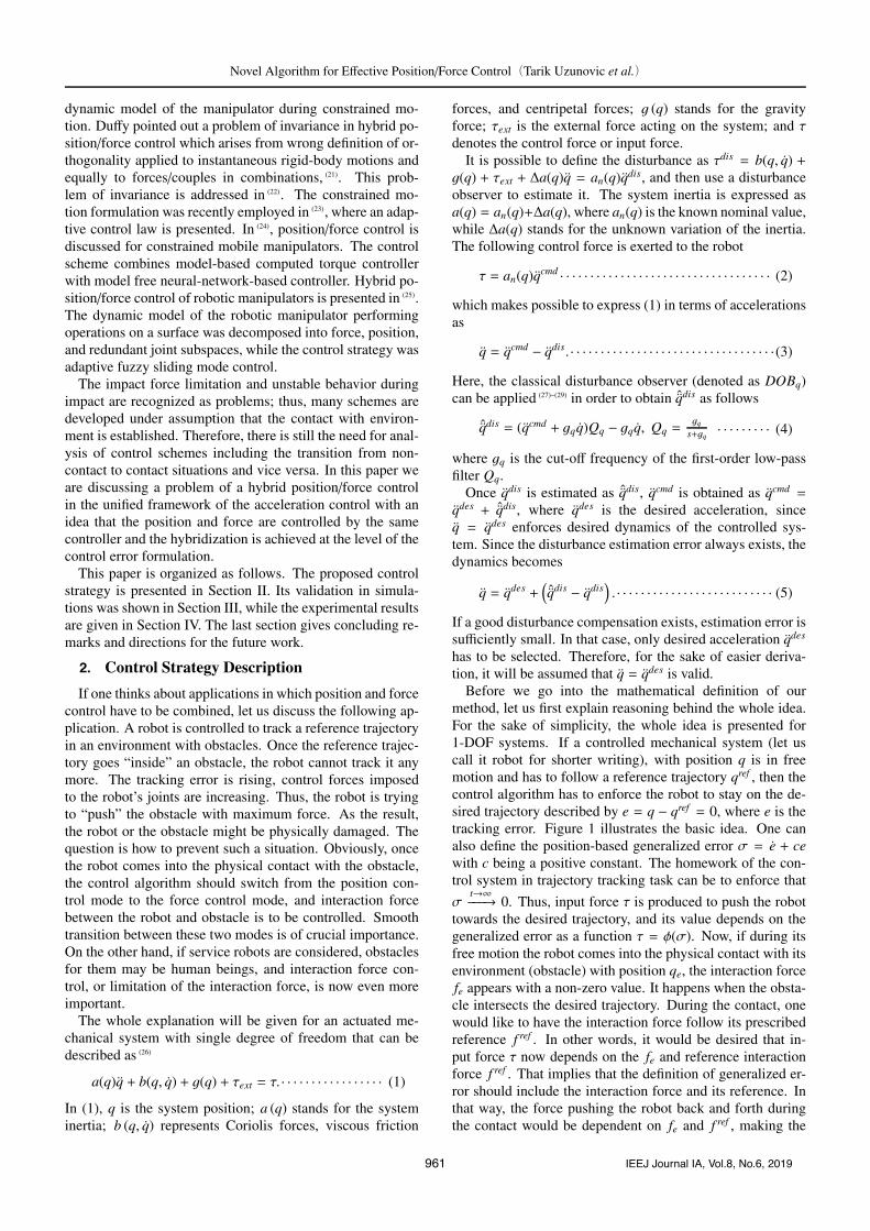
− = f ref = 3.5 N,while the reference position was given as qref = 0.003 +0.019 sin(2π f · t) m, f = 0.2 Hz. This experiment was createdto check whether the proposed method could be used in tra-jectory tracking tasks, but with present limit on the maximuminteraction force imposed to the environment. The recordedresults are depicted in Figs. 7 and 8.
The obtained responses show satisfactory performance ofthe controller. In free motion, reference trajectory is suc-cessfully tracked. After the contact with environment isestablished, the interaction force is controlled not to over-come 3.5 N. It is important to note that smooth transition be-tween position tracking and force control is achieved, and nooscillatory behavior is observed in the controlled quantities,
964 IEEJ Journal IA, Vol.8, No.6, 2019
Novel Algorithm for Effective Position/Force Control(Tarik Uzunovic et al.)
Fig. 7. Position responses in experiment 1
Fig. 8. Force responses in experiment 1
i.e., there is no so-called “woodpecker phenomenon”.The force response shows some issues that exist with in-
teraction force estimation. The estimation requires precisedynamical model of the controlled system, so that only un-known force is the external interaction force. In this sce-nario, the interaction force can be estimated using a distur-bance observer. However, since some small interaction forceis estimated even when no contact exists between the sys-tem and environment, this implies that some unmodeled dy-namics is still present. Nevertheless, it does not negate theconclusion about the effectiveness of the presented controlstrategy. Force estimation is not in the focus of this paper.If it was improved, the overall control performance would beimproved.4.3 Experiment 2 In the second experiment, the
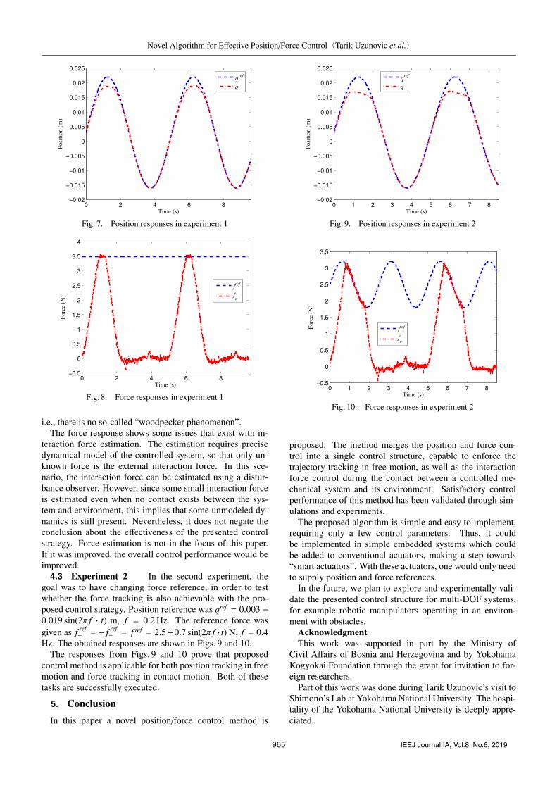
goal was to have changing force reference, in order to testwhether the force tracking is also achievable with the pro-posed control strategy. Position reference was qref = 0.003 +0.019 sin(2π f · t) m, f = 0.2 Hz. The reference force wasgiven as f ref
+ = − f ref− = f ref = 2.5+0.7 sin(2π f · t) N, f = 0.4
Hz. The obtained responses are shown in Figs. 9 and 10.The responses from Figs. 9 and 10 prove that proposed
control method is applicable for both position tracking in freemotion and force tracking in contact motion. Both of thesetasks are successfully executed.
5. Conclusion
In this paper a novel position/force control method is
Fig. 9. Position responses in experiment 2
Fig. 10. Force responses in experiment 2
proposed. The method merges the position and force con-trol into a single control structure, capable to enforce thetrajectory tracking in free motion, as well as the interactionforce control during the contact between a controlled me-chanical system and its environment. Satisfactory controlperformance of this method has been validated through sim-ulations and experiments.
The proposed algorithm is simple and easy to implement,requiring only a few control parameters. Thus, it couldbe implemented in simple embedded systems which couldbe added to conventional actuators, making a step towards“smart actuators”. With these actuators, one would only needto supply position and force references.
In the future, we plan to explore and experimentally vali-date the presented control structure for multi-DOF systems,for example robotic manipulators operating in an environ-ment with obstacles.
AcknowledgmentThis work was supported in part by the Ministry of
Civil Affairs of Bosnia and Herzegovina and by YokohamaKogyokai Foundation through the grant for invitation to for-eign researchers.
Part of this work was done during Tarik Uzunovic’s visit toShimono’s Lab at Yokohama National University. The hospi-tality of the Yokohama National University is deeply appre-ciated.
965 IEEJ Journal IA, Vol.8, No.6, 2019

Novel Algorithm for Effective Position/Force Control(Tarik Uzunovic et al.)
References
( 1 ) G. Zhong, Z. Shao, H. Deng, and J. Ren: “Precise position synchronous con-trol for multi-axis servo systems”, IEEE Trans. Ind. Electron., Vol.64, No.5,pp.3707–3717 (2017)
( 2 ) H. Du, X. Chen, G. Wen, X. Yu, and J. Lu: “Discrete-time fast terminalsliding mode control for permanent magnet linear motor”, IEEE Trans. Ind.Electron. (2018) DOI: 10.1109/TIE.2018.2815942
( 3 ) X. Zhang, T. Shi, Z. Wang, Q. Geng, and C. Xia: “Generalized predictivecontour control of biaxial motion system”, IEEE Trans. Ind. Electron. (2018)DOI: 10.1109/TIE.2018.2808899
( 4 ) W. Zhao, S. Jiao, Q. Chen, D. Xu, and J. Ji: “Sensorless control oflinearpermanent-magnet motor based on improved disturbance observer”,IEEE Trans. Ind. Electron. (2018) DOI: 10.1109/TIE.2018.2823660
( 5 ) K. Zhang, J. Xu, H. Chen, J. Zhao, and K. Chen: “Jamming analysis andforce control for flexible dual peg-in-hole assembly”, IEEE Trans. Ind. Elec-tron. (2018) DOI: 10.1109/TIE.2018.2838069
( 6 ) S. Chen, Z. Chen, B. Yao, X. Zhu, S. Zhu, Q. Wang, and Y. Song: “Adap-tive robust cascade force control of 1-dof hydraulic exoskeleton for humanperformance augmentation”, IEEE/ASME Trans. Mechatronics, Vol.22, No.2,pp.589–600 (2017)
( 7 ) R. Cortesao and M. Dominici: “Robot force control on a beating heart”,IEEE/ASME Trans. Mechatronics, Vol.22, No.4, pp.1736–1743 (2017)
( 8 ) A. Sabanovic: “Challenges in motion control systems”, IEEJ Journal of In-dustry Applications, Vol.6, No.2, pp.107–116 (2017)
( 9 ) T. Oomen: “Advanced motion control for precision mechatronics: Control,identification, and learning of complex systems”, IEEJ Journal of IndustryApplications, Vol.7, No.2, pp.127–140 (2018)
(10) T.T. Phuong, K. Ohishi, C. Mitsantisuk, Y. Yokokura, K. Ohnishi, R. Oboe,and A. Sabanovic: “Disturbance observer and kalman filter based motioncontrol realization”, IEEJ Journal of Industry Applications, Vol.7, No.1,pp.1–14 (2018)
(11) Q. Xu: “Design and smooth position/force switching control of a miniaturegripper for automated microhandling”, IEEE Trans. Ind. Informat., Vol.10,No.2, pp.1023–1032 (2014)
(12) G. Wang and Q. Xu: “Design and precision position/force control of a piezo-driven microinjection system”, IEEE/ASME Trans. Mechatronics, Vol.22,No.4, pp.1744–1754 (2017)
(13) B. Huard, M. Grossard, S. Moreau, and T. Poinot: “Sensorless force/positioncontrol of a single-acting actuator applied to compliant object interaction”,IEEE Trans. Ind. Electron., Vol.62, No.6, pp.3651–3661 (2015)
(14) M.H. Raibert and J.J. Craig: “Hybrid position/force control of manipulators”,J. Dynamic Syst. Meas. Control, Vol.103, No.2, pp.126–133 (1981)
(15) M.T. Mason: “Compliance and force control for computer controlled manip-ulators”, IEEE Trans. Syst., Man, Cybern., Vol.11, No.6, pp.418–432 (1981)
(16) O. Khatib: “A unified approach for motion and force control of robot manip-ulators: The operational space formulation”, IEEE Journal of Robotics andAutomation, Vol.3, No.1, pp.43–53 (1987)
(17) T. Yoshikawa: “Dynamic hybrid position/force control of robotmanipulators–description of hand constraints and calculation of joint drivingforce”, IEEE J. Robot. Autom., Vol.3, No.5, pp.386–392 (1987)
(18) S. Chiaverini, B. Siciliano, and L. Villani: “Force/position regulation ofcompliant robot manipulators”, IEEE Trans. Autom. Control, Vol.39, No.3,pp.647–652 (1994)
(19) A. De Luca and C. Manes: “Modeling of robots in contact with a dynamicenvironment”, IEEE Trans. Robot. Autom., Vol.10, No.4, pp.542–548 (1994)
(20) J. K. Mills and A.A. Goldenberg: “Force and position control of manipulatorsduring constrained motion tasks”, IEEE Trans. Robot. Autom., Vol.5, No.1,pp.30–46 (1989)
(21 ) J. Duffy: “The fallacy of modern hybrid control theory that is based on “or-thogonal complements” of twist and wrench spaces”, Journal of Robotic Sys-tems, Vol.7, No.2, pp.139–144 (1990)
(22) J. De Schutter, D. Torfs, H. Bruyninckx, and S. Dutre: “Invariant hybridforce/position control of a velocity controlled robot with compliant end ef-fector using modal decoupling”, The International Journal of Robotics Re-search, Vol.16, No.3, pp.340–356 (1997)
(23) P. Gierlak and M. Szuster: “Adaptive position/force control for robot ma-nipulator in contact with a flexible environment”, Robotics and AutonomousSystems, Vol.95, pp.80–101 (2017)
(24) M. Rani, N. Kumar, and H.P. Singh: “Efficient position/force control of con-strained mobile manipulators”, International Journal of Dynamics and Con-trol, pp.1–10 (2018)
(25) A.K. Ravandi, E. Khanmirza, and K. Daneshjou: “Hybrid force/positioncontrol of robotic arms manipulating in uncertain environment based onadaptive fuzzy sliding mode control”, Applied Soft Computing (2018)
https://doi.org/10.1016/j.asoc.2018.05.048.(26 ) A. Sabanovic and K. Ohnishi: Motion control systems, John Wiley & Sons,
Singapore (2011)(27) K. Ohishi, K. Ohnishi, and K. Miyachi: “Torque-speed regulation of DC mo-
tor based on load torque estimation”, in Proceedings of the IEEJ InternationalPower Electronics Conference, Vol.2, pp.1209–1216 (1983)
(28) T. Murakami and K. Ohnishi: “Observer-based motion control-application torobust control and parameter identification”, in Proc. Asia-Pacific Workshopon Advances in Motion Control, pp.1–6 (1993)
(29) K. Ohnishi, M. Shibata, and T. Murakami: “Motion control for advancedmechatronics”, IEEE/ASME Trans. Mechatronics, Vol.1, No.1, pp.56–67(1996)
(30) T. Murakami, F. Yu, and K. Ohnishi: “Torque sensorless control inmultidegree-of-freedom manipulator”, IEEE Trans. Ind. Electron., Vol.40,No.2, pp.259–265 (1993)
Tarik Uzunovic (Non-member) received the B.Eng. and M.Eng. de-grees in electrical engineering from the Universityof Sarajevo, Sarajevo, Bosnia and Herzegovina, andPh.D. degree in mechatronics from Sabanci Univer-sity, Istanbul, Turkey, in 2008, 2010, and 2015, re-spectively. He is an Assistant Professor with the De-partment of Automatic Control and Electronics, Fac-ulty of Electrical Engineering, University of Sarajevo,Sarajevo, Bosnia and Herzegovina. His research in-terests include motion control, robotics, and mecha-
tronics.
Asif Sabanovic (Non-member) received the B.S., M.S., and Dr.Sci.degrees in electrical engineering from the Universityof Sarajevo, Sarajevo, Bosnia and Herzegovina, in1970, 1975, and 1979, respectively. He is an Emeri-tus Professor at Sabanci University, Istanbul, Turkey.From 1970 until 1991, he was with Energoinvest -Institute for Control and Computer Sciences, Sara-jevo. In 1991, he was with the Department of Elec-trical Engineering, University of Sarajevo. He was aVisiting Researcher with the Institute of Control Sci-
ences, Moscow, Russia, Visiting Professor with the California Institute ofTechnology - CALTECH, Pasadena, Hitachi Chair Professor with Keio Uni-versity, Yokohama, Japan, Full Professor with Yamaguchi University, Ube,Japan, Head of CAD/CAM and Robotics Department at Tubitak - MarmaraResearch Centre, Istanbul. His research interests include control systems,motion control systems, robotics, mechatronics, and power electronics.
Minoru Yokoyama (Student Member) received the B.E. and M.E.degrees in electrical and computer engineering fromYokohama National University, Yokohama, Japan, in2015 and 2017, respectively. He is currently workingtoward the Ph.D. degree at Yokohama National Uni-versity. His research interests include mechatronics,motion control and haptics.
Tomoyuki Shimono (Senior Member) received the Ph.D. degree inintegrated design engineering from Keio University,Yokohama, Japan in 2007. From 2007 to 2008, hewas a Research Fellow of the Japan Society for thePromotion of Science. From 2007 to 2008, he wasalso a Postdoctoral Fellow at Keio University. From2008 to 2009, he was a Research Associate with theGlobal Centers of Excellence Program, Keio Univer-sity. Since 2009, he has been with the Department ofElectrical and Computer Engineering, Yokohama Na-
tional University, Yokohama, where he is currently an Associate Professor.His research interests include haptics, motion control, medical and rehabili-tation robots, and actuators.
966 IEEJ Journal IA, Vol.8, No.6, 2019