notice to dealers - vintage sno to dealers this manual is ... 1. driven torque converter 2. shims 4....
TRANSCRIPT
Notice to Dealers
This manual is provided to ensure that the snowmobile is assembled correctly and given proper presale preparation . Your customer expects and deserves a safe, reliable snowmobile, and performance of the steps listed here is essential to that, end.
The selling dealer assumes sole responsibility for any unauthorized modifications prior to sale . Refer to your Snow Products Binder for any Service Bulletins specifying Factory Directed Modifications (Special Claims) which must be performed before the snowmobile is ready for sale .
SAFETY AWARENESS
I WARNING I THIS WARNING SYMBOL IDENTIFIES SPECIAL INSTRUCTIONS OR PROCE DURES WHICH, IF NOT CORRECTLY FOLLOWED, COULD RESULT IN PERSONAL IN JURY, OR LOSS OF LIFE.
THIS CAUTION SYMBOL IDENTIFIES SPECIAL INSTRUCTIONS OR PROCEDURES WHICH, IF NOT STRICTLY OBSERVED, COULD RESULT IN DAMAGE TO, OR DESTRUCTION OF EQUI PMENT.
Whenever you see the symbols shown above, heed their instructions! Always follow safe operating and maintenance practices.
)
c Table of Contents Assembly .. .. ........ ...... ..................................... ........... .. .................................................................. 2
Uncrate .............. ................. ... .... ......... .. .... ............. ... ........... ....... ........................................... 2 Skis ..................................................................... ................................................................... 2 Suspension ......................... ... .. ...... .. .............................................................. ...... .. ................ 2 Windshield ............. ................ ........................... ...... ......... ........ ... ... .... .... .......... ..... ......... ....... 3 Handlebar ...... ..................... ......................... ... .................. ... ..... ...... ..... .... ........................... ... 3 Tool Kit / Owner Manual .... .... ...... .... .. .... ....... ......... ........ ....... ............................................... 4 Safety Labels .................. ..... .... ..... .... .... ......................... .. ......... ............ .. ......... ..................... 4
Preparation ..... .. .. ........ ......... .. ................ ......... .... .. ......... .. . .... .... ........... .... .................................... 4 Steering Alignment .... ............... ........ ......................... .................................................... ...... 4 Drive and Driven Converter Alignment ................................. .. ......................................... 5 Center to Center Distance ................ ............................ ........ .. .... .................. .......... ............ 5 Offset Distance ..................... .. .. .. ........................ .... ............. ................................................. 6 Parallelism ..... ...... .......... ..... .... .. ..................................................... ........................................ 6 Cha incase ......... ..................................................................................................................... 7 Brake ..... .... .... ...... .............. ........... ..... .. ............ ............................ ............. .............................. 8 Wiring Harness ....................................... .... ........... ....... ....................................................... 8 Cooling System .................................................................................................................... 8 Oil Pump Gearcase .. ... .. ....................... .... ........................................................................... 8 Oil Tank ........ .......... ................. .............................................................................................. 9 Fuel / Oil Mixture (Ratio) ......... ... ..... ............................................. ..... ............. ...................... 9 Fue l ................ ..... ....... .. ............................ ..... ......................................................................... 9 Enrichener Control... .......................... .. ................................. ....... ..... ....... .................. .......... 9 Throttle Cable ... ..... ........................... .. ....... ................... .............. .. ...................................... 10 Synchronization of Oil Pump and Carburetors .............................................................. 10 Spark PI ugs .......................... ............................................................................................... 10 Carburetor Adjustments ...................... ... .............. .............. ............................................... 11 Air Screw .................................... ................... .... .............. .... ......... ................. ...... ............... 11 Idle Screw .................... ....................... ................................................................................ 11 Ignition Timing Adjustment .................. .. ....................................... ........ ...... ...... .... .......... . 11 Headlight Adjustment .. ..... ...... .......................... ................................................................. 12 Tail / Brake Light ....................................................................................... ....... .... ..... ..... .... . 12 Track Adjustments .. .... ...... ...... ..... ....................................................................... ..... .......... 13 Track Tension ......... .................... .... .......................................... .......................................... 13 Track Alignment ....................................... ......... ....................................... .................. ........ 14
Test Ride (Operational Checks) ...... .... ........ .. ..................................... ........ ................ .... ........ . 14 Specifications ..... ...... ...... ..... ............ ........................................ ..... ....... .... ..... .............. ............... 15
Eng ine ...... ..... ................................. .. ....... ....................... ..... ......... ...... .................................. 15 Carburetor Setti ngs ......................... .. .. ......................... .. ... .... .. ......... ..... ............................. 15 Fuel ............ ................................................................. ................. .. ........................ ..... ......... 15 Drive System ...... .......... .. ...... .. ............ ............................ .... .. ........ ........ ... ..................... .. .... 15 Electrical System ............... ....... ................................ ..................... ..................................... 15 Torque Chart ......................................................................... ..... ....... ............... ... .............. .. 15
Wiring Diagram ....................... .. ............................................................................ .. ......... ......... 16
TABLE OF CONTENTS 1

Assembly Uncrate
Remove the top and side panels from the crate with a pry bar. Remove the plastic cover ing over the snowmobile by carefully cutting around t he base of the crate. Remove windshield from seat. Cut strapping and remove skis and packing. See Figure 1.
Unscrew the nuts securing the ski spindles to the skid. See Figure 2 .
1. Ski Spi ndle 2. Ski Attitude Bumper
IWARNINGI
To prevent personal injury, use lifting equipment with approved safety hooks when raising the snowmobile.
With assistance, or the use of a hoist, carefully lift the snowmobile from the skid. Thoroughly inspect the snowmobile for shipping damage and missing parts.
2 ASSEMBLY
Skis
With one si de of snowmobile raised, instal l ski attitude bu mper as shown, then inst all the skis with the bolts provided. Torque the nuts 28 to 32 foot pounds (3.9 to 4. 5 kg -m). Install both skis and return the snowmobile to its upr ight position. See Figure 3.
3
Suspension
The snowmobil e is shipped wi t h t he suspension spr ings at lowest preload. See Fi gure 4.

1. Position the snowmobile on its side on a pro -tective surface and tighten the front suspension spring adjusting nuts to 1 inch (25.4 mm) when measured from the washer face to the end of the adjusting bolt .
Always adjust the preload (tension) of the springs on each side of the suspension arm equal/y. Unequal tension can cause spring breakage or excessive wear to one side of the slider wear strips. See Figure 5.
1. Cam in Second Position 2. Suspension Spring Adjusting Nut
2. Adjust the rear shock / spring cam to the second position, using cam wrench which is included in tool kit .
1. Second Position 2. Spanner Wrench 3. Cam
The suspension spring preload settings given are for average driver weight. The operator may change the suspension adjustment, to satisfy rider comfort, by following the procedure outlined in the Owner Manual.
Windshield Remove the protective film and install the wind shield with the fasteners provided. See Figure 7.
Handlebar
Adjust the handlebar for a comfortable driving position and evenly torque the four Allen screws 7 to 9 foot pounds (1 .0 to 1.2 kg-m) . See Figure 8 .
[~!:~2~J Adjust the handlebar so it does not hit the windshield, when turning i n either direction.
Check the routi ng of the cables and wire harnesses for proper positioning. They should pass through the cutaway section in the console to provide adequate free movement of the handlebars. See Figure 8 .
1. Cutaway Section of Console
ASSEMBLY 3

Tool Kit/Owner M anual Check the storage box to be sure it conta ins t he Tool Kit and Owner M anual.
Safety Labels ""1 W- A-R- N- I-N-G-",
Insure that all safety decals are properly located and secure. See Figure 9 .
4 PR EPARATION
9
Preparation
Steering Alignment
Check the ski alignment and handlebar centering.
1. Place a long board (or suitable straight edge) against the righthand edge of the track and measure the clearance between the board and ski . Position the righthand ski so that the clear ance measured is the same at the front and rear of the ski. See Figure 10.
1. Straight Edge Against Track 2. Measure Clearance Here
NOTE: Be sure the ski remains parallel to the straight edge while turning the tie rod length adjusting stud.
2. Check the handlebar for centering . If centering is required, loosen the lock nuts and turn the tie rod length adjusting stud to center the handlebar. See Figure 11.
IWARNINGt
The dimension shown must not exceed 1 -1 / 4 inch (32 mm) to prevent possible steering linkage failure. See Figure 11.
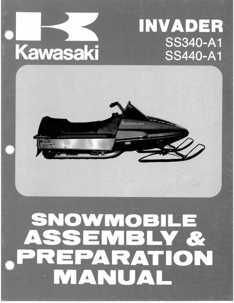
1. Tie Rod Length Adjusting Stud 2. Locknuts 3. 1- 114 Inch (32 mm) Maximum
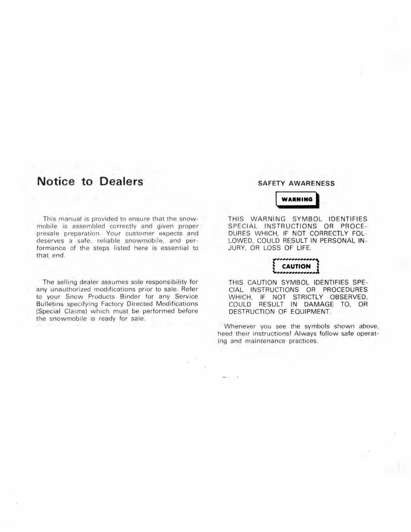
3. To align the other ski, move both ski tips toward the center of the snowmobile to remove the steering linkage play. Loosen the tie rod end locknuts and turn the tie rod to obtain equal distance from ski to ski when measured at the front and rear of the skis. See Figure 12.
4. Torque all the hardware (nuts, bolts, etc.) in the steeri ng system. Refer to the torque chart for the recommended values.
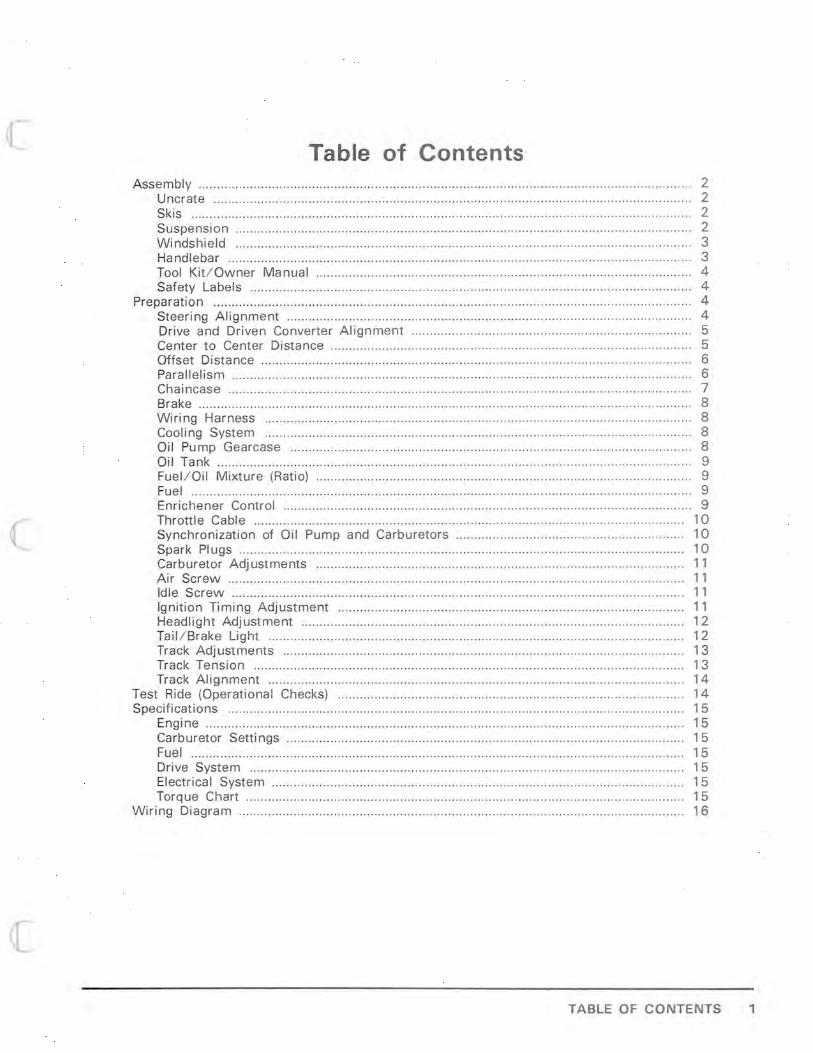
Drive and Driven Converter Alignment
Correct converter center -to-center distance of 12.0 inches (304.8 mm), and converter offset distance 0.588 inches (14.9 mm) is obtained when align ment gauge PI N 57001-3503 is correctly installed between drive and driven converter sheaves. Figure 13.
1. Alignment Gauge PI N 57001 -3503
Center-To-Center Distance
1. Remove belt guard and remove drive belt.
2. Rotate driven converter moveable sheave assembly clockwise, and insert alignment gauge between sheaves . Carefully release moveable sheave assembly allowing spring tension to retain gauge in position between stationary and moveable sheave assemblies.
3. Position opposite end of alignment gauge over drive converter shaft.
4 . If adjustment of the converter center distance is required, loosen the four mounting nuts on the chaincase and the jackshaft bearing support bolts. Push forward or rearward on the jacks haft until alignment gauge can be installed between the drive and driven converters. See Figure 13. Tighten the bearing support bolts and the chaincase mounting nuts. Position head of adjusting bolt against beari ng support and secure with lock nut. See Figures 14 and 15.
PREPARATION 5

1. Bearing Support Bolts 2. Adjusting Bolt Lock Nut 3. Adjusting Bolt 4. Bearing Support
1. Mounting Nuts
Offset Distance
1. Correct off set distance 0.588 inches (14.9 mm) is obtained when drive converter sta tionary sheave fits against recess of alignment gauge when gauge is positioned on shaft.
2. If adjustment is necessary, remove left side aluminum trim from lower pan by removing mounting hardware. See Figure 16. Lower pan is notched to allow driven converter removal.
6 REPA ATION
3. Remove the large bolt that retains the driven converter to the jackshaft and remove the driven converter. See Figures 16 and 17.
1. Aluminum Trim 2. Retaining Bolt
1. Driven Torque Converter 2. Shims
4. Add or remove shims from the bore of the driven converter to obtain the 0.588 inch (14.9 mm) offset. See Figures 17 and 18.
5. Reinstall the driven converter. Secure with retaining bolt torqued to 55 to 60 Ft . Lbs. (7.61 to 8.30 kg -mI.
SHIMS AVAILABLE
PI N THICKNESS
92025-3501 .032 INCHES (0.81 mm) 92025-3502 .063 INCHES (1.60 mm) 92025-3503 .100 INCHES (2. 54 mm)
18

Parallelism
1. When checking the center-to-center and offset distances, parallelism must be checked by measuring dimensions A and B as shown in Figure 19. Compare dimensions A and B against Notes I, II , and III.
1. Distance "A" 2. Distance "B" 3 . Alignment Gauge PI N 57001-3503
NOTE I: Dimension A must be more than dimen sion B.
NOTE II: Dimension A must never exceed dimension B by more than 1/ 16 inch (1.6 mm).
NOTE III: If dimension A is more than dimension B, correct offset as described in Offset Distance.
2. If dimension A is less than dimension B, parallelism between engine crankshaft and driven pulley is not correct. Parallelism must be adjusted as follows:
a. Loosen the large bolt in each of the two engine mounts on the right side of the engine.
b. Move the right side of the engine either toward the front or rear whichever is necessary.
c. Securely tighten the large bolts in the two engine mounts after parallelism is obtained.
Chaincase
NOTE: Use DEXRON " Automatic Transmission Fluid when fill i ng the chaincase.
Check the chaincase fluid level. Fluid level must be between the center and the top of the window. If additional fluid is required, remove the upper plug in the chaincase and pour DEXRON " automatic transmission fluid into the chaincase until correct level is attained. This provides the proper lubrication for the chain and bearings . See Figure 20.
1. Upper Fill Plug 2. Fluid Level Window
PREPARATION 7
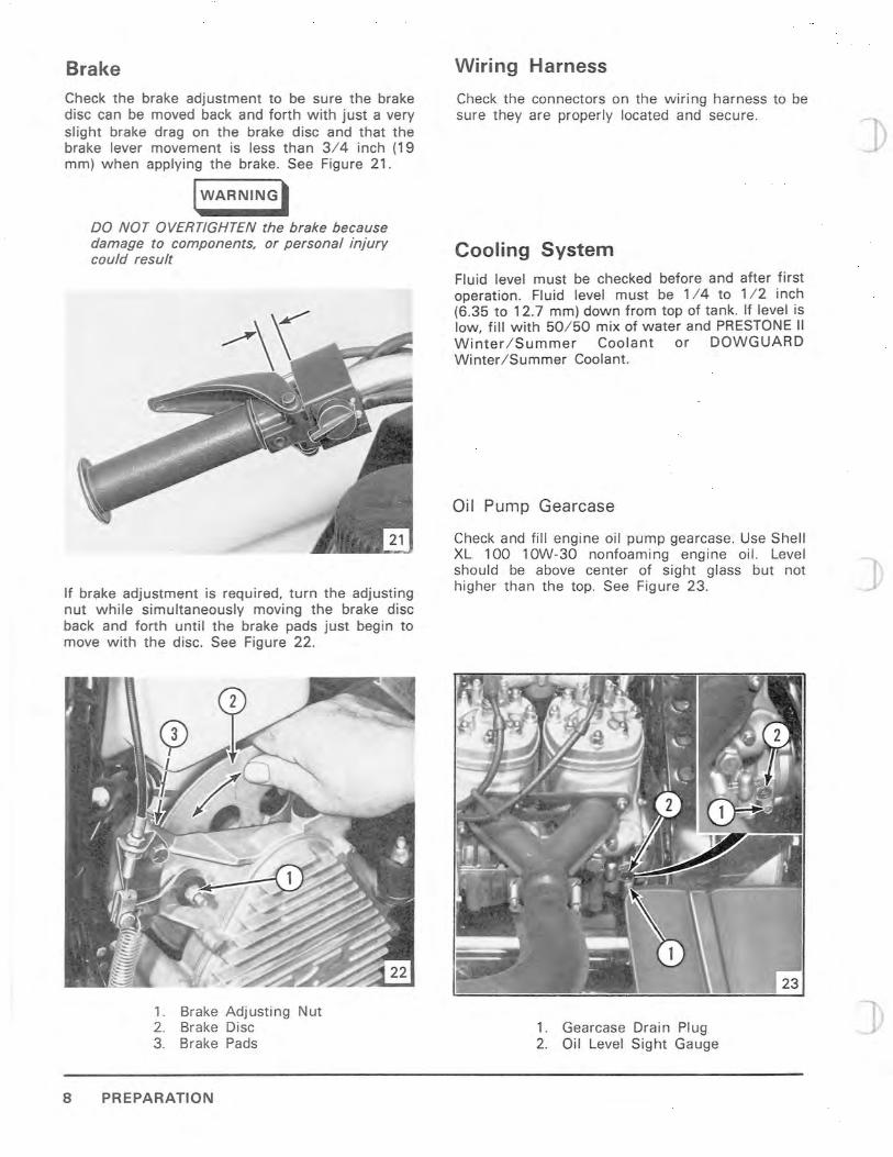
Brake Check the brake adjustment to be sure the brake disc can be moved back and forth with just a very slight brake drag on the brake disc and that the brake lever movement is less than 3/4 inch (19 mm) when applying the brake. See Figure 21.
IWARNING'
DO NOT OVERTIGHTEN the brake because damage to components, or personal injury could result
If brake adjustment is required, turn the adjusting nut while simultaneously moving the brake disc back and forth until the brake pads just begin to move with the disc. See Figure 22.
1. Brake Adjusting Nut 2. Brake Disc 3. Brake Pads
8 PREPARATION
Wiring Harness
Check the connectors on the wiri ng harness to be sure they are properly located and secure.
Cooling System Fluid level must be checked before and after first operat ion. Fluid level must be 114 to 112 inch (6.35 to 12.7 mm) down from top of tank. If level is low, fill with 50/50 mix of water and PRESTONE II Winter I Summer Coolant or DOWGUARD Winter ISummer Coolant.
Oil Pump Gearcase
Check and fill engine oil pump gearcase. Use Shell XL 100 10W-30 nonfoaming engine oil. Level should be above center of sight glass but not higher than the top. See Figure 23.
1. Gearcase Drain Plug 2. Oil Level Sight Gauge
(
Oil Tank
We recommend using Kawasaki Snowmobile oil. This oil is specially formulated to give minimum piston ring varnish and combustion chamber deposits along with excellent lubrication qualities. Oil tank capacity is 2-112 quarts (2.37 liters). THE OIL TANK HAS NO FILTER. DO NOT ALLOW DIRT TO ENTER WHILE FILLING.
The use of fuel additives such as "tune-up tonics" and "super oils" are NOT RECOMMENDED.
In an emergency situation when Kawasaki Snowmobile Oil is not available a B.I.A. certif ied TC-W oil may be substituted.
After filling the oil tank for the first time, disconnect the oil line at the pump and, allow the air to bleed out.
Failure to bleed the air out of the oil line can cause severe engine damage.
Fuel / Oil Mixture (Ratio)
The fuel-to-oil ratio required is automatica lly controlled at the engine oil pump.
The oil pump is a variable ratio pump, at idle th e fuel / oil ratio is approximately 110 to 1 increas ing with throttle posit ion to approximate ly 25 to 1 at maximum power.
Fuel
Use leaded gasoline with a minimum PUMP POST OCTANE NUMBER of 89.
I WARNING'
Gasoline fumes are heavier than air and can become explosive if exposed to a pilot light from a furnace, hot water heater, clothes dryer, etc. Fill the fuel tank only in an area that is well ventilated and free from pilot lights and sparks.
Before removing filler cap from the fuel tank, remove any ice, snow, or water from around the fuel tank opening to prevent contamination of fresh fuel mixture.
Fill the fuel tank slowly and pour the fuel into the tank using a funnel with a fine mesh screen.
Each time gas tank is filled - check for adequate oil level fill the oil tank with KA WASAKI SNOWMOBILE OIL. A full oil tank assures proper oil/ fuel ratio will be maintained to prevent serious engine damage.
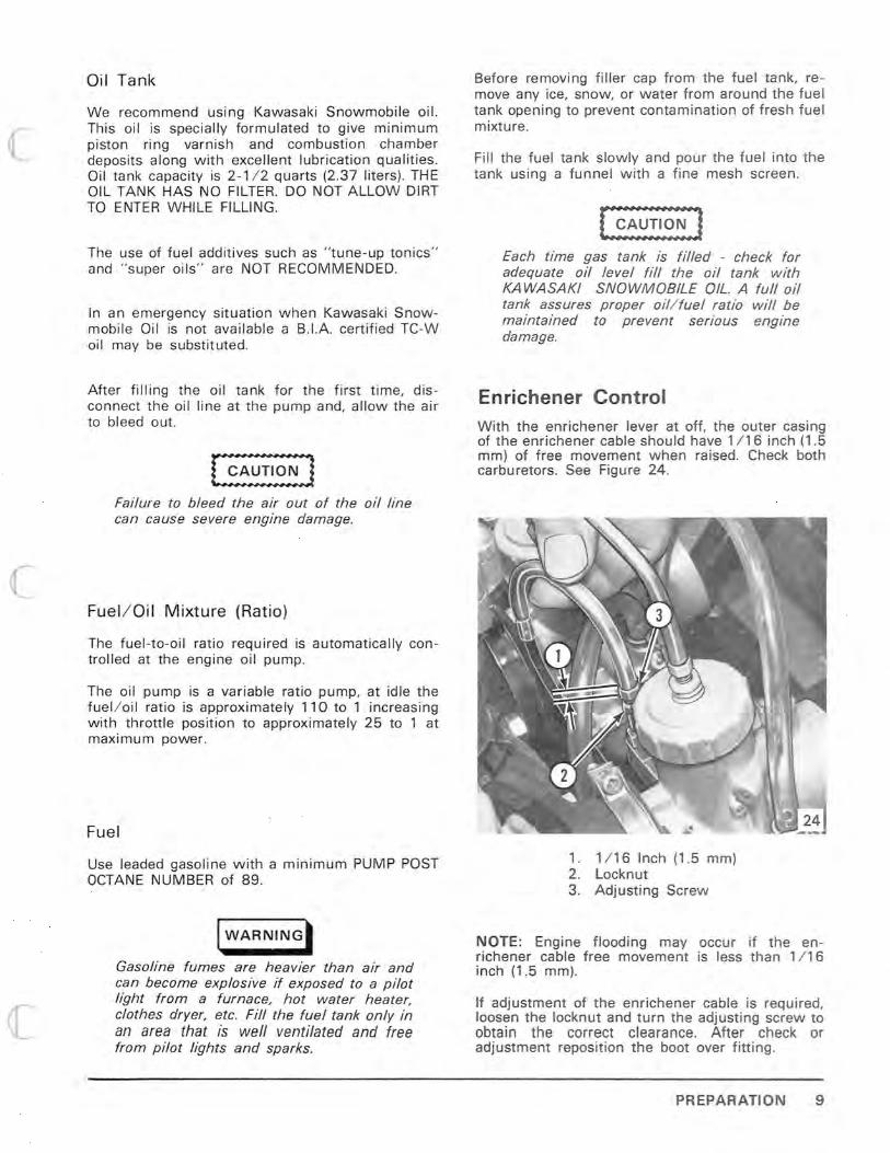
Enrichener Control With the enrichener lever at off, the outer casing of the enrichener cable shou ld have 1/16 inch (1.5 mm) of free movement when raised. Check both carburetors. See Figure 24.
1. 1/16 Inch (1.5 mm) 2. Locknut 3. Adjusting Screw
NOTE: Engine flooding may occur if the enri chener cable free movement is less than 1/16 inch (1.5 mm).
If adjustment of the enrichener cable is required, loosen the locknut and turn the adjusting screw to obtain the correct clearance. After check or adjustment reposition the boot over fitting .
PREPARATION 9

Throttle Cable
If a gap between the throttle lever and handlebar grip is present when the lever is at full throttle, excessive stress may be placed on the throttle cable ends which could cause cable failure.
With the air silencer removed from the carburetors, hold the throttle lever at the full throttle position and check that:
1. The throttle slides inside the carburetor bores open fully and are synchronized.
2. The throttle lever is tight against the handle-bar grip.
If adjustment of the throttle is required, loosen the locknut, and turn the adjusting screw on the throttle cable as required, and tighten the locknut. See Figure 25. Replace intake silencer.
When reinstalling intake silencer the intake hose must be directed rearward. Failure to do so will cause engine damage.
1. Locknut 2. Adj usti ng Screw 3. Air Screw 4. Idle Stop Screw
10 PREPARATION
25
Synchronization of Oil Pump and Carburetors To assure adequate oil to the engine, synchronize the carburetors and oil pump by the following procedure:
1. Remove intake silencer assembly by disconnecting four springs.
2. Loosen throttle idle stop screws so the slides are bottomed out.
3. Adjust carburetor control cables so they are equal and all slack is taken up. Do the same for the oil contro l lever cable. Tighten locking nuts.
4. Throttle slides and pump lever should start to move in unison, when throttle lever is moved.
5. Replace intake silencer and secure with four springs.
Spark Plugs
Adjust the spark plug gap to 0.024 inch (0.6 mm). See Figure 26.
Before installing the spark plugs, be sure the washer is installed and the seat on the cylinder head is clean. Install the spark plug and torque it 18 to 20 foot pounds (2.5 to 2.8 kg -mI.
26
1. Gap 2. Washer
)

Carburetor Adjustments
Air Screw
The carburetor air screw is properly adjusted when opened 1.5 to 2 turns off its seat. Refer to the specifications page and see Figure 25.
Idle Screw
The idle speed screw initial adjustment is 3 turns open from coil bound, (screw turned in tight), refer to the specifications page. Refer to the tachometer and adjust the engine idle speed to 3,000 R.P.M. See Figure 25.
Make sure the fuel pump pulse line, all the fuel lines and all oil lines are secure and free of kinks or sharp bends.
Ignition Timing Adjustment
1. Remove recoil starter. Remove the right hand side spark plug and install a dial indicator in the spark plug hole. See Figure 27.
1. Dial Indicator
2. Position the recoil side piston at 0.108 inch (2.75 mm) before top dead center.
3. Check that the "F" mark on the flywheel aligns with fixed mark on the magneto housing .
4. Remove the dial indicator and replace the spark plug and lead wire.
5. Connect a strobe type timing light to the right hand side spark plug lead, follow light manufacturer's instructions. See Figure 28. Use the snowmobile tachometer to measure R.P.M.
1. Timing Light
6. With torque converter belt removed and guard secured in place, start the engine with emergency start rope on drive converter, run at approximately 6,000 R.P.M., and direct the timing light at the fixed mark on the magneto housing. The ignition timing is correct when the "F" mark on the flywheel appears in alignment with the fixed mark on the magneto housing as the light flashes. Shut off engine.
I WARNING'
Do not touch the spark plug leads while engine is running as they will transmit a powerful electrical shock. Do not touch the hot exhaust system. A severe burn would result.
7. If the timing is incorrect, loosen the stator plate screws through holes in the flywheel, and reposition the stator plate as necessary. See Figure 29.
PREPARATION 11

When adjusting the stator plate, take care not to damage the coil windings.
8. Tighten the stator plate screws and recheck timing.
9. When the ignition timing is correct, remove the timing light and replace the recoil starter.
Headlight Adjustment 1. Position the snowmobi le on a leve l floor so the
headlight points at a wall 25 feet (7,620 mm) away. The headlight must be in the up and locked position.
2. Measure the distance from the floor to the center of the headlight and mark the wall at the dimension measured (reference mark). See Figure 30.
30
1. Wall 2. 25 Feet (7,620 mm) 3. Reference Mark (center of headlight to floor) 4 . 2 Inches (51 mm) Below Reference Mark
12 PREPARATION
IWARNINGI
If adjusting the headlight indoors, provide proper ventilation to prevent possible carbon monoxide poisoning.
NOTE: Be sure an operator is seated on the snowmobi le wh ile the engine is running to prevent the vehicle from creeping ahead, and to assure proper aiming.
3. Turn on the headlight high beam. The headlight is properly aimed when the high beam is centered and aimed 2 inches (51 mm) below the reference mark on the wall. See Figure 30.
4 . If headlight adjustment is required, turn the adjusting screws as required. See Figure 31.
1. Horizontal Adjusting Screws 2. Vertical Adjusting Screws
Check the operation of the headlight low beam.
Tail/Brake Light The taillight will operate only when the key switch is in the "Run/Lights" position.
The brake light is activated by a switch mounted in the brake lever housing on the handlebar. Brake light operation is independent of the other lights and the key switch.
r-I W-A-R-N-I N-G--',
Whenever the outer casing of the brake cable is repositioned readjustment of the brake is required. Failure to readjust the brake could result in component damage or personal injury.

If the brake lever does not return to the full off posit ion, the brake switch will remain on, causing the brake l ight to glow constantly. To allow full return of the brake lever, loosen the lock nuts on the brake cable outer cas ing and move the outer casing fu rther aw ay from the return spring. Recheck the brake lever fo r full return to off and t ighten the lock nuts on the outer casing. See Fig ure 32.
1. Locknuts 2. Return Spring
Track Adjustments
I WARNING'
While raising the snowmobile off the gr ound, place the skis against a stationary object, and be sure the vehicle is properly secured, to prevent personal injury.
Track Tension
IWARNINGt
To prevent personal injury, never adjust track tension with the engine running.
1. With the track off the ground for its entire length, brace the snowmobile so it cannot fall, then hang a 5 to 8 pound (2.2 to 3.6 kg) we ight from the mid point of the track.
2. The clearance from the bottom of the wear strip to the top of the track should be 3 / 4 inch (19 mm) when measured directly below the rear suspension pivot arm bolt. See Figure 33.
1. 3 / 4 Inch (19 mm)
1. Idler Wheel 2. Rear Axle Locking Bolts
3. If necessary, adjust by loosening the rear axle locking bolts turn the rear axle adjusting bolts as requi red to obtain the specified wear stripto-t rack clearance. See Figure 34 and 35.
4. When the proper tension is attained, be sure both adj usting bolts are the same length when measured from the bolt end to the rear axle bracket . See Figure 35. This is a good starting point for track alignment .
1. Rear Axle Adj usting Nuts
PREPARATION 13

Track Alignment
Ir"" W-A-R-N-I-N-G"'""l,
To prevent injury, never adjust or measure track alignment while the engine is running.
Remove the weight from the track, start the engine and push the throttle only enough to turn the track slowly a few revolutions, then stop the engine and allow track to coast to a stop, and check the alignment.
The track is aligned when the distance between the rear idler wheel and edge of the track is equal on both sides. See Figure 36.
If the track runs to one side, tighten the rear axle adjusting bolt on the same side, approximately 1/2 turn, then restart the engine and recheck the alignment.
When track alignment is correct. tighten the rear axle locking bolts.
1. Idler Wheel 2. Edge of Track 3. Dimension Equal On Both Sides 4. Rear Axle Locking Bolts
Test Ride (Operational Checks) Test ride the snowmobile and check for the following:
14 TEST RIDE (OPERATIONAL CHECKS)
• CONTROL CABLES
The throttle and brake controls must operate without binding and return freely in any steering position.
• STEERING
Steering should be smooth and free from lock to- lock with no excessive looseness in the steering linkage.
• ENGINE
Recoil starter works properly and the engine starts promptly. Test for good throttle re sponse and return.
• SUSPENSION
Adjusted for average driver weight and operates smoothly.
• EMERGENCY STOP SWITCH
Check operation in all switch positions .
• CONVERTERS
Test for smooth operation and correct engine R.P.M. (340) 7,800 (440) 8,000 at full throttle.
• BRAKES
When activated, the brakes should result in adequate smooth stopping of the track; when released, there should be no brake drag.
• INSTRUMENTS
Check for proper indications.
During the test ride, listen for any unusual noises (rattles, squeaks, etc.) that may warrant inspection and correction.
When the test ride is completed, open the hood and thoroughly inspect the engine compartment for fuel or oil leaks.
Check engine gearcase oil level. Level should be above center of sight glass but not above the top. Use Shell XL 100 10W-30 non -foaming oil.
Retorque torque converter bolt 50 to 60 foot pounds (7 .6 1 to 8.30 kg-mI. Bend tab of special lockwasher up against a flat on the bolthead to lock in place.

SPECIFICATIONS
ENGINE
Type ... ... .. ..... .. ...... .. .... ..... .. .... .. . ...... . .......... .. .. . ... ... .. ... ... .. . ....... .... ...... ....... .... ... .... .. . ...... .. (340) TC340A (440) TC440A
Displacement ... ... .... ...... .... .... ..... ... ......... .... .... .. ... ........ .. ...... ... ........ ...... .... (340) 20.7 C.1. (339.3 cc) (440) 26.6 C.1. (436 cc)
Bore X Stroke .... ..... ...... .. .... .. ...... .... ................... .. ...... (340) 2.362 x 2.362 inches (60 x 60 mm) (440) 2.677 x 2.362 inches (68 x 60 mm)
Number of Cylinders ..... ... ... ........ .. ............................................... ....................... ... .......... ... ............. 2 Ignition System ............ ...... .. .... .... .... ............ .. ... .. .. ...... .. ...... .. .... .. ........ ... Capacitor Discharge (C. D.) Ignition Timing .... .............................................................. .. ........... 0.108 inch B.T.D.C. (2.75 mm) Spark Plug ................. .. ...... .. ... ..... ......... .... ......... .... ....... .... .... ...... .... ....... .... ..... .......... ... NGK BR-9 EV Spark Plug Gap .... ...... .... ...... .. .... .. ...... .. ........... .... .. ... .. .. .. .. .. .. .. ........ .. .. ........ .... . 0 .024 inch (0.6 mm) Carburetor Make and Model .... ... .... ........ .. .. ....... .. .... ....... ................................ (340) Mikuni VM32
(440) Mikuni VM36 Engine R.P.M . at Full Throttle .. ................ .. ..................................................... (340) 7,800 R.P.M.
(440) 8,000 R.P.M.
CARBURETOR SETTINGS
Air Screw ........ ...... .. .......... .. ........ .. .............. .... .... .. .... ........ ...... .... .... .. .. .... ........ .... .. 1.5 turns off seat Idle Screw .. .. ..... ... ... .... .. .. .. .. ...... ..... .. . 3 turns open from coil bound initial (3,000 R.P.M. final)
FUEL
Gasol ine ...... .... .. ... .. ....................................... Leaded minimum pump posted octane number 89 Oil .... .... .... ...... ...... ...... .. ................ .. .......... Kawasaki Snowmobile Oil or B.I.A. certified TC"W oil Gasoline / Oil Ratio .. ..... ................ ...... .... ....... ... ..... .... ........... ..... .. ..... .... .......................... Oil Injection
DRIVE SYSTEM
Dr ive Be lt Width .. .... .. .. .... .. ...... .. .. ...... ... ..................... .... ... .... ... .. .. .. ........... 1-1/4 inches (31.7 mm) Drive Belt Outside Circumference ........ .. .. .. .. ........ .... .... .... .. .. .. ...... ..... 46-5/ 8 inches (1,184 mm) Converter Offset ............ .. .. .. .... .... .. .. ............ .... ... .. ....... ... ...... .. ............ .. .. ... 0.588 inches (14.9 mm) Converter Center Distance ' ...... .. .... ...... .. .. .... .. .. ... ....... .. ...... ... ... ........ .. .. ....... 12 inches (304.8 mm)
ELECTRICAL SYSTEM
Type .... .. ........ .. ...... .. ..................... .. .. .. .... .... ..... ...... .................. .. .... .... ............... 12 Volts - 120 Watts Headlight ..... .. ....... .. .. .... ...... .. .. .... .... .... ..... .... ................ .. .... .. ... .............. ........ ....... .... .. .. Stanley A5988 Tail/Brake Light ..... .. ... ....... ...... .. .. .. ........................ .. ........ .. .. .... ........ .. .. .. ........ ...... .... .. G.E. No. 1157 Instrument Lights .............. .. ....... .. ........... ........ ....... .. .. ... .. .... ... ... ............ ... .. ......... ..... ... .. .. G.E. No. 57
TORQUE CHART
TOOL SIZE BOLT DIAMETER RECOMMENDED TORQUE
10 mm 6 mm 5 TO 6 ft Ibs (0.7 TO 0.8 kg -m)
7 / 16 inch 1/ 4 7 TO 9 ft Ibs (1 .0 TO 1.2 kg-m)
112 inch 5/ 16 14 TO 18 ft Ibs (2.0 TO 2.5 kg -m)
9 / 16 inch 3/ 8 28 TO 32 ft Ibs (3 .9 TO 4.5 kg-m)
5/ 8 & 11 / 16 inch 7/ 16 47 TO 52 ft Ibs (6.5 TO 7.2 kg-m) --..--J
SPECIFICATIONS 15

... O'l
~ JJ
Z G')
o l> G') JJ l> S
HAN OLE BAR STOP SWITCH IGNITION COIL
A zJIIL: OFF ~ 6 OFF
BRAKE LIGH T SWITCH
UJ w ;;: WHIT E ----L-:::J :::J 0
ti ---t?J ...J ...J 0: BLACK to to en
CO l " u
(y <l: <l: ;;: ,,' ...J ...J W 0
'" en KEY SWITCH :::J ...J
~
(~ ...J ...J
l I en w BLACK "OFF" GM >-
BLUE "RUN / LIG HTS" BL
f BLUE "RUN" NONE w " z BROWN
~~)~ 0 f- U ;;: 0 I <l: 0 w ;;: ...J
~ lJXl w w BLUE
0: en 0: 0:
r--.. ~ ~ GRAY BLACK
0 0
h ...J ...J ...J ...J
BLACK " w w YELLOW/ REO >- >- r--.. TACHOMETER
w BROWN BROWN RED
r=10 STOP - TA I L LIGHT
f-~~7 0 I YELLOW
~ w
'" 0: ;;: ~
BROWN YELLOW YELLOW
I vr--~. / BROWN YELLOW BLACK
/ ENGINE ~ECTOR I (0/ r--
'/ LIGHTING COIL (-V A BLACK ( ~ !/ TEMP GAGE LIGHT SPEEDOMETER -' '" '/ 0 '--- ) , - - - - - - -, LIGHT
;: TACHOMETER LIGHT z 0 ;;: ;: 0 ...J
~ I I 0 0 W ...J BROWN ...J 0: z 0: w 7: '0' I '0'
;;: ~ >-...J en Z w '--- t-----< 0 0 ~ >- 0: ...J ;:
I "- I "- en ...J 0 BROWN (BRAKE LIGHT)
~ YELLOW w 0: "
ENGINE MAGNETO I w ~ I z >- en
"I I BROWN YELLOW (COMMON)
I i 0 I ;;: ::' I ;;: ~ I ~ I h. YELLOW (TAIL LIGHT)
en ;;:
V I I ;;: I -:-- ' Sf
0 0 ...J W
L ___ --1 ...J 0: -- W
~ >-- YELLOW· RED VOLTAGE REGULATOR Z 0 ...J ;;: ...J
BROWN /YELLOW 0 w 0: >-
YELLOW RED en BROWN (INPUT)
"-/ :J BEAM SWITCH
BROWN/ YELLOW GREEN (HI )
ORANGE (LO)
~ HEADLIGHT -
~ BROWN/ YE LLOW <f )--
GREEN (HI ) ./ GREEN "-
ORANGE (LO) l-'>. "- ORANGE
/