notice no. 9 - cdlive.lr.org · table 2.2.1 type notations 2.4 class notations (machinery) (part...
TRANSCRIPT
The status of this Rule set is amended as shown and is now to be read in conjunction with this and priorNotices. Any corrigenda included in the Notice are effective immediately.
Issue date: July 2014
Notice No. 9Rules and Regulations for theClassification of Ships, July 2013
Working togetherfor a safer world
Amendments to Effective date
Part 1, Chapter 2, Sections 2 & 3
Part 1, Chapter 3, Sections 1, 2, 5, 7, 8, 9 & 14
Part 3, Chapter 2, Sections 1 & 2Part 3, Chapter 6, Section 7Part 3, Chapter 9, Section 2
Part 3, Chapter 11, Section 2Part 3, Chapter 12, Section 5Part 3, Chapter 16, Section 2
Part 4, Chapter 2, Section 4Part 4, Chapter 5, Section 8Part 4, Chapter 8, Sections 1, 3, 14 & 15
Part 4, Chapter 9, Section 12Part 7, Chapter 3, Sections 3 & 4
Part 8, Chapter 2, Sections 1, 2, 6 & 12
1 July 2014
1 July 2014
1 July 2014
1 July 20141 July 20141 July 2014
1 July 20141 July 2014
1 July 20141 July 2014
1 July 20141 July 20141 July 2014
1 July 2014
Effective Date 1 July 2014
■ Section 2Character of classification andclass notations
2.1 Definitions
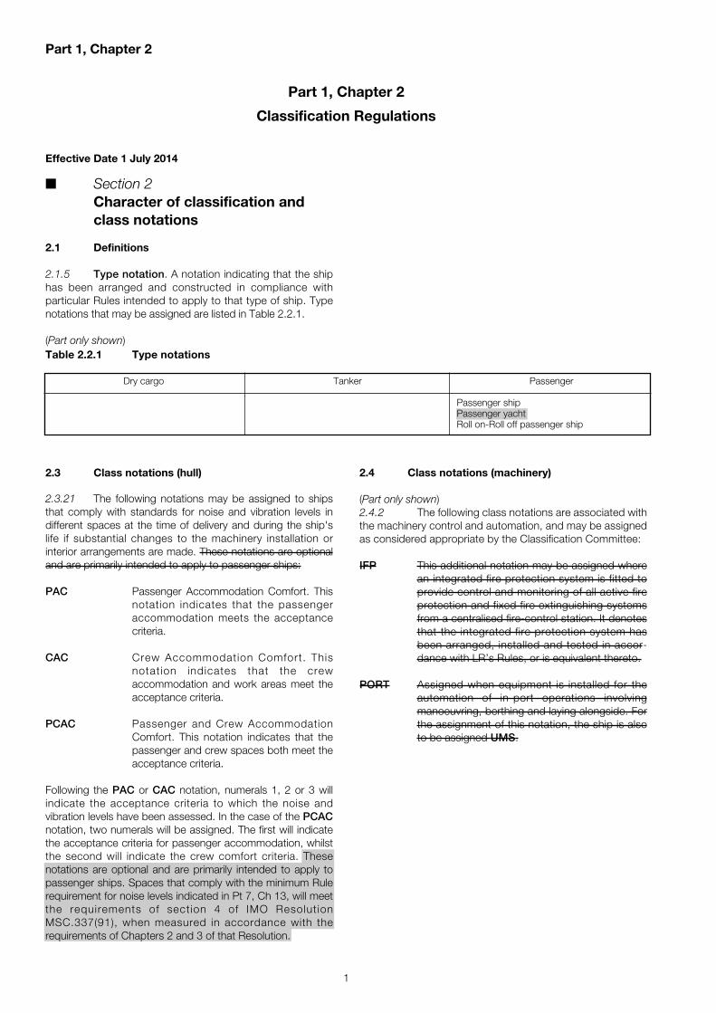
2.1.5 Type notation. A notation indicating that the shiphas been arranged and constructed in compliance with particular Rules intended to apply to that type of ship. Typenotations that may be assigned are listed in Table 2.2.1.
(Part only shown)
2.3 Class notations (hull)
2.3.21 The following notations may be assigned to shipsthat comply with standards for noise and vibration levels indifferent spaces at the time of delivery and during the ship'slife if substantial changes to the machinery installation orinterior arrangements are made. These notations are optionaland are primarily intended to apply to passenger ships:
PAC Passenger Accommodation Comfort. Thisnotation indicates that the passengeraccommodation meets the acceptancecriteria.
CAC Crew Accommodation Comfort. Thisnotation indicates that the crewaccommodation and work areas meet theacceptance criteria.
PCAC Passenger and Crew AccommodationComfort. This notation indicates that thepassenger and crew spaces both meet theacceptance criteria.
Following the PAC or CAC notation, numerals 1, 2 or 3 willindicate the acceptance criteria to which the noise andvibration levels have been assessed. In the case of the PCACnotation, two numerals will be assigned. The first will indicatethe acceptance criteria for passenger accommodation, whilstthe second will indicate the crew comfort criteria. Thesenotations are optional and are primarily intended to apply topassenger ships. Spaces that comply with the minimum Rulerequirement for noise levels indicated in Pt 7, Ch 13, will meetthe requirements of section 4 of IMO ResolutionMSC.337(91), when measured in accordance with therequirements of Chapters 2 and 3 of that Resolution.
Part 1, Chapter 2
1
Part 1, Chapter 2
Classification Regulations
Dry cargo Tanker Passenger
Passenger shipPassenger yachtRoll on-Roll off passenger ship
Table 2.2.1 Type notations
2.4 Class notations (machinery)
(Part only shown)2.4.2 The following class notations are associated withthe machinery control and automation, and may be assignedas considered appropriate by the Classification Committee:
IFP This additional notation may be assigned wherean integrated fire protection system is fitted toprovide control and monitoring of all active fireprotection and fixed fire extinguishing systemsfrom a centralised fire-control station. It denotesthat the integrated fire protection system hasbeen arranged, installed and tested in accor-dance with LR’s Rules, or is equivalent thereto.
PORT Assigned when equipment is installed for theautomation of in-port operations involvingmanoeuvring, berthing and laying alongside. Forthe assignment of this notation, the ship is alsoto be assigned UMS.

2
Part 1, Chapter 2
(Part only shown)
2.8 Descriptive notes
2.8.7 STV. Where a sailing vessel is used for theoffshore training of cadets or trainee seamen, a sailingtraining vessel STV descriptive note may be entered incolumn 6 of the Register Book.
■ Section 3Surveys – General
3.8 Withdrawal/Suspension of class
3.8.4 Class will be automatically suspended from theexpiry date of the Certificate of Class in the event that theSpecial Survey has not been completed by the due date andan extension has not been agreed (see 3.5.9), or is not underattendance by the Surveyors with a view to completion priorto resuming trading.Classification will be reinstated from suspension of class uponsatisfactory completion of the surveys due. The surveys to becarried out are to be based upon the survey requirements atthe original date due and not on the age of the ship when thesurvey is carried out. Such surveys are to be credited fromthe date originally due. However, the ship’s Class remainssuspended from the date of suspension until the date Class isreinstated.
3.8.14 For reclassification and reinstatement of class, see3.3.2 and 3.8.4.
Table 2.2.4 Machinery Class Notations
Machinery NotationsSee 2.4, 2.5, 2.6
IPIntegrated Propulsion
IFPIntegrated Fire Protection
PORTAutomation of in-port operation onlyassigned to addition to UMS
DP(CM)Dynamic Position(Centralised Remote Manual Controls)
PMRL*Propulsion System Redundancy in SeparateCompartments with Limited Capacity
SMRLSteering System Redundancy with LimitedCapacity
SMRL*Steering System Redundancy in SeparateCompartments with Limited Capacity
PSMRLPropulsion and Steering System Redundancywith Limited Capacity
(CA)Controlled Atmosphere
CA (%O2, %CO2)Controlled Atmosphere
RHRelative Humidity
Part 1, Chapter 3
3
■ Section 2Annual Surveys – Hull andmachinery requirements
2.2 Annual Surveys
2.2.10 The bilge pumping systems and bilge wells, includingoperation of extended spindles and level alarms, where fitted,are to be examined so far as practicable. Satisfactory operation of the bilge pumps is to be proven. The bilge pumpingsystems for each watertight compartment, including bilgewells, extended spindles, self-closing drain cocks, valves fittedwith rod gearing or other remote operation, pumps and levelalarms, where fitted, are to be examined and operated as faras practicable and all confirmed to be satisfactory. Any handpumps provided are to be included.
■ Section 5Special Survey – General – Hullrequirements
5.3 Examination and testing
5.3.5 Double bottom, deep, ballast, peak and othertanks, including cargo holds assigned also for the carriage ofsalt water ballast, are to be tested with a head of liquid to thetop of air pipes or to near the top of hatches for ballast/cargoholds. Boundaries of oil fuel, lubricating oil and fresh watertanks are to be tested with a head of liquid to the highest pointthat liquid will rise to under service conditions. Tank testing ofoil fuel, lubricating oil and fresh water tanks may be speciallyconsidered based upon a satisfactory external examination ofthe tank boundaries, and a confirmation from the Master stat-ing that the pressure testing has been carried out according tothe requirements with satisfactory results. Surveyors mayextend the testing as deemed necessary.For oil tankers (including ore/oil and ore/bulk/oil ships) andchemical tankers, the minimum requirements for cargo tanktesting are to be in accordance with Sections 7.5 and 8.5, asapplicable.
■ Section 7Special Survey – Oil tankers(including ore/oil ships andore/bulk/oil ships) – Hullrequirements
7.5 Testing
7.5.1 The minimum ballast tank testing requirements aregiven in Table 3.7.1 and, where required, the Surveyor mayextend the tank testing if deemed necessary. The remainingrequirements for tank testing, as applicable, are given in 5.3.5.
Effective Date 1 July 2014
■ Section 1General
1.5 Definitions
1.5.18 For the application of requirements outlined inSections 2, 3, 4 and 5, a general dry cargo ship is a self-propelled ship of 500 gross tonnes or above, constructedgenerally with a ‘tween deck and intended to carry solidcargoes, other than:• bulk carriers;• ships dedicated to the carriage of containers;• dedicated forest product carriers (but not timber or log
carriers);• roll on-roll off ships;• refrigerated cargo ships;• dedicated wood chip carriers;• dedicated cement carriers;• livestock carriers;• dock/deck cargo ships;• general dry cargo ships of double side-skin construction,
with double side-skin extending for the entire length ofthe cargo area, and for the entire height of the cargo holdto the upper deck.
1.6 Preparation for survey and means of access
1.6.5 For surveys, including close-up survey where applicable, in cargo spaces and ballast tanks, one or more ofthe following means of access, is to be provided:(a) Permanent staging and passages through structures.(b) Temporary staging and passages through structures.(c) Lifts Hydraulic arm vehicles such as conventional cherry
pickers, lifts and movable platforms.(d) Portable ladders, see Note.(e) Boats or rafts.(f) Other equivalent means.NOTE
Portable ladders may be used, at the discretion of the Surveyor,for survey of the hull structure of single skin bulk carriers,except for the close-up survey of cargo hold shell frames, see1.6.6 and 1.6.7.
1.6.11 Rescue and emergency response equipment: ifbreathing apparatus and/or other equipment is used as‘rescue and emergency response equipment’, i t isrecommended that the equipment be suitable for theconfiguration of the space being surveyed.
Existing paragraph 1.6.11 has been renumbered 1.6.12.
Part 1, Chapter 3
Periodical Survey Regulations
Part 1, Chapter 3
4
■ Section 9Ships for liquefied gases
9.7 Special Survey I (ships five years old) –General requirements
9.7.6 For membrane containment systems, a tightnesstest of the primary and secondary barrier shall be carried outin accordance with the system designer’s procedures andacceptance criteria as approved by LR. Low differential pressuretests may be used for monitoring the cargo containmentsystem performance, but are not considered an acceptabletest for the tightness of the secondary barrier. For membranecontainment systems with glued secondary barriers, thevalues obtained shall be compared with previous results orresults obtained at the new-building stage. If significant differences are observed for each tank or betweentanks, then an evaluation and additional testing, as requiredby the Surveyor, is to be carried out if the designer’s thresholdvalues are exceeded, an investigation is to be undertaken andadditional testing such as thermographic or acoustic emissionstesting should be carried out.
■ Section 14Electrical equipment
14.2 Complete Surveys
14.2.4 Air circuit-breakers for essential or emergencyservices and rated at 800 A and above are to be surveyed toensure that the manufacturer’s recommended number ofswitching options has not been exceeded. See Pt 6, Ch2,7.3.6. Where a breaker is not fitted with an automaticcounter, a written record is to be kept.
Existing paragraphs 14.2.4 and 14.2.5 have been renumbered14.2.5 and 14.2.6.
14.2.6 14.2.7 Where transformers associated withsupplies to essential services are liquid-immersed, the Owneris to arrange for samples of the liquid to be taken and testedfor dissolved gases, breakdown voltage, acidity and moistureby a competent testing authority, in accordance with theequipment manufacturer’s requirements, and a certificategiving the test results is to be furnished made available to theSurveyor on request.
Existing paragraphs 14.2.7 to 14.2.9 have been renumbered14.2.8 to 14.2.10.
14.2.10 14.2.11 Where the ship is electrically propelled, the propulsion motors, generators, propulsion transformers,propulsion conversion equipment, cables, harmonic filters,neutral earthing resistors, dynamic braking resistors and allancillary electrical gear equipment that forms part of thepropulsion drive and control system, exciters and ventilatingplant (including coolers) associated therewith are to be examinedsurveyed, and the insulation resistance to earth is to be tested.Special attention is to be given to windings, commutators and
7.5.2 The minimum cargo tank testing requirements aregiven in Table 3.7.1; boundaries of cargo tanks are to betested to the highest point that liquid will rise to under serviceconditions.Cargo tank testing carried out by the ship’s crew under thedirection of the Master may be accepted by the Surveyorprovided the following conditions are complied with:(a) A tank testing procedure has been submitted by the
Owner and reviewed by LR prior to the testing beingcarried out.
(b) There is no record of leakage, distortion or substantialcorrosion that would affect the structural integrity of thetank.
(c) The tank testing has been satisfactorily carried out withinthe special survey window not more than 3 months priorto the date of the survey on which the overall or close-upsurvey is completed.
(d) The satisfactory results of the testing are recorded in theship’s logbook.
(e) The internal and external condition of the tanks andassociated structure is found satisfactory by theSurveyor at the time of the overall and close-up survey.
■ Section 8Special Survey – Chemical tankers –Hull requirements
8.5 Testing
8.5.1 The minimum ballast tank testing requirements aregiven in Table 3.8.1 and, where required, the Surveyor mayextend the tank testing if deemed necessary. Other arrange-ments for cargo tank testing will be considered on application.The remaining requirements for tank testing, as applicable,are given in 5.3.5
8.5.2 The minimum cargo tank testing requirements aregiven in Table 3.8.1, boundaries of cargo tanks are to betested to the highest point that liquid will rise to under serviceconditions. Other arrangements for cargo tank testing will beconsidered on application.Cargo tank testing carried out by the ship’s crew under thedirection of the Master may be accepted by the Surveyorprovided the following conditions are complied with:(a) A tank testing procedure has been submitted by the
Owner and reviewed by LR prior to the testing beingcarried out.
(b) There is no record of leakage, distortion or substantialcorrosion that would affect the structural integrity of thetank.
(c) The tank testing has been satisfactorily carried out withinthe special survey window not more than 3 months priorto the date of the survey on which the overall or close-upsurvey is completed.
(d) The satisfactory results of the testing are recorded in theship’s logbook.
(e) The internal and external condition of the tanks andassociated structure is found satisfactory by theSurveyor at the time of the overall and close-up survey.
Part 1, Chapter 3 & Part 3, Chapter 2
5
■ Section 2Fracture control
2.1 Grades of steel
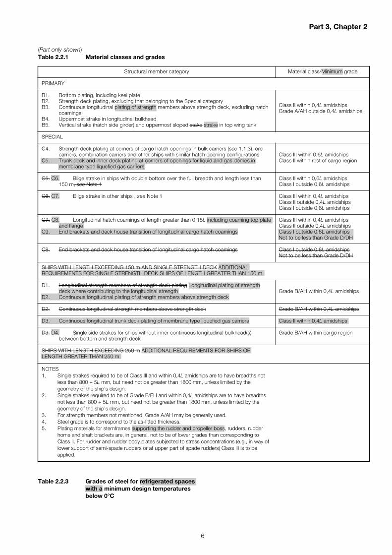
2.1.2 In order to distinguish between the material graderequirements for different hull members, material classes areassigned as given in Table 2.2.1. Steel grades are to be notlower than those corresponding to the material classes asgiven in Table 2.2.2.
2.1.2 In order to distinguish between the material graderequirements for different hull members at varying locationsalong the ship, material classes are assigned as shown inTable 2.2.1. For each class, depending on thickness, thematerial grade requirements are not to be lower than thosegiven in Table 2.2.2.
Effective Date 1 July 2014
■ Section 1Materials of construction
1.3 Aluminium
1.3.1 The use of aluminium alloy is permitted for specialpurpose craft, and for superstructures, deckhouses, hatchcovers, helicopter platforms, or other local components onboard ships.
1.3.1 The use of aluminium alloy is permitted for super-structures, deckhouses, hatch covers, helicopter platforms,or other local components on board ships.
Part 3, Chapter 2
Materials
slip-rings. Where practicable, the low voltage and high voltagewindings of cast resin propulsion transformers are to besubjected to boroscopic inspection, to assess the physicalcondition of their insulation and for signs of mechanical andthermal damage. The operation of protective gear and alarmdevices is to be checked, so far as practicable. Insulating oil,if used, is to be tested in accordance with 14.2.6 14.2.7.Interlocks intended to prevent unsafe operations or unauthorisedaccess are to be checked to verify that they are functioningcorrectly. Emergency overspeed governors are to be tested.
Existing paragraphs 14.2.11 and 14.2.12 have been renumbered 14.2.12 and 14.2.13.
Part 3, Chapter 2
6
(Part only shown)
Structural member category
PRIMARY
B1. Bottom plating, including keel plateB2. Strength deck plating, excluding that belonging to the Special categoryB3. Continuous longitudinal plating of strength members above strength deck, excluding hatch
coamingsB4. Uppermost strake in longitudinal bulkheadB5. Vertical strake (hatch side girder) and uppermost sloped stake strake in top wing tank
SPECIAL
C4. Strength deck plating at corners of cargo hatch openings in bulk carriers (see 1.1.3), orecarriers, combination carriers and other ships with similar hatch opening configurations
C5. Trunk deck and inner deck plating at corners of openings for liquid and gas domes inmembrane type liquefied gas carriers
C5. C6. Bilge strake in ships with double bottom over the full breadth and length less than 150 m, see Note 1
C6. C7. Bilge strake in other ships , see Note 1
C7. C8. Longitudinal hatch coamings of length greater than 0,15L including coaming top plateand flange
C9. End brackets and deck house transition of longitudinal cargo hatch coamings
C8. End brackets and deck house transition of longitudinal cargo hatch coamings
SHIPS WITH LENGTH EXCEEDING 150 m AND SINGLE STRENGTH DECK ADDITIONALREQUIREMENTS FOR SINGLE STRENGTH DECK SHIPS OF LENGTH GREATER THAN 150 m.
D1. Longitudinal strength members of strength deck plating Longitudinal plating of strengthdeck where contributing to the longitudinal strength
D2. Continuous longitudinal plating of strength members above strength deck
D2. Continuous longitudinal strength members above strength deck
D3. Continuous longitudinal trunk deck plating of membrane type liquefied gas carriers
D3. D4. Single side strakes for ships without inner continuous longitudinal bulkhead(s)between bottom and strength deck
SHIPS WITH LENGTH EXCEEDING 250 m ADDITIONAL REQUIREMENTS FOR SHIPS OFLENGTH GREATER THAN 250 m.
NOTES1. Single strakes required to be of Class III and within 0,4L amidships are to have breadths not
less than 800 + 5L mm, but need not be greater than 1800 mm, unless limited by thegeometry of the ship’s design.
2. Single strakes required to be of Grade E/EH and within 0,4L amidships are to have breadthsnot less than 800 + 5L mm, but need not be greater than 1800 mm, unless limited by thegeometry of the ship’s design.
3. For strength members not mentioned, Grade A/AH may be generally used.4. Steel grade is to correspond to the as-fitted thickness.5. Plating materials for sternframes supporting the rudder and propeller boss, rudders, rudder
horns and shaft brackets are, in general, not to be of lower grades than corresponding toClass II. For rudder and rudder body plates subjected to stress concentrations (e.g., in way oflower support of semi-spade rudders or at upper part of spade rudders) Class III is to beapplied.
Material class/Minimum grade
Class II within 0,4L amidshipsGrade A/AH outside 0,4L amidships
Class III within 0,6L amidshipsClass II within rest of cargo region
Class II within 0,6L amidshipsClass I outside 0,6L amidships
Class III within 0,4L amidshipsClass II outside 0,4L amidshipsClass I outside 0,6L amidships
Class III within 0,4L amidshipsClass II outside 0,4L amidshipsClass I outside 0,6L amidshipsNot to be less than Grade D/DH
Class I outside 0,6L amidshipsNot to be less than Grade D/DH
Grade B/AH within 0,4L amidships
Grade B/AH within 0,4L amidships
Class II within 0,4L amidships
Grade B/AH within cargo region
Table 2.2.1 Material classes and grades
Table 2.2.3 Grades of steel for refrigerated spaceswith a minimum design temperaturesbelow 0°C
Part 3, Chapter 6
7
7.5.1 7.5.2 Where the propeller shafting is exposed tothe sea for some distance clear of the main hull, it is generallyto be supported adjacent to the propeller by independentbrackets having two arms. In very small ships, the use ofsingle arm brackets will be specially considered.
Existing paragraphs 7.5.2 and 7.5.3 have been renumbered7.5.3 and 7.5.4.
7.5.4 The scantlings of shaft brackets will be speciallyconsidered and, in the case of certain high powered ships,direct calculations may be required.
Existing paragraph 7.5.5 has been renumbered 7.5.6.
7.5.5 In the case of certain high powered ships, directcalculations may be required and scantlings of shaft bracketswill be specially considered.
7.6 Double arm shaft brackets (‘A’ – brackets)
7.6.1 The angle between the arms for double arm shaftbrackets is generally to be not less than 50°. Proposals forthe angle between the arms to be less than 50° will bespecially considered with supporting calculations to besubmitted by the designers.
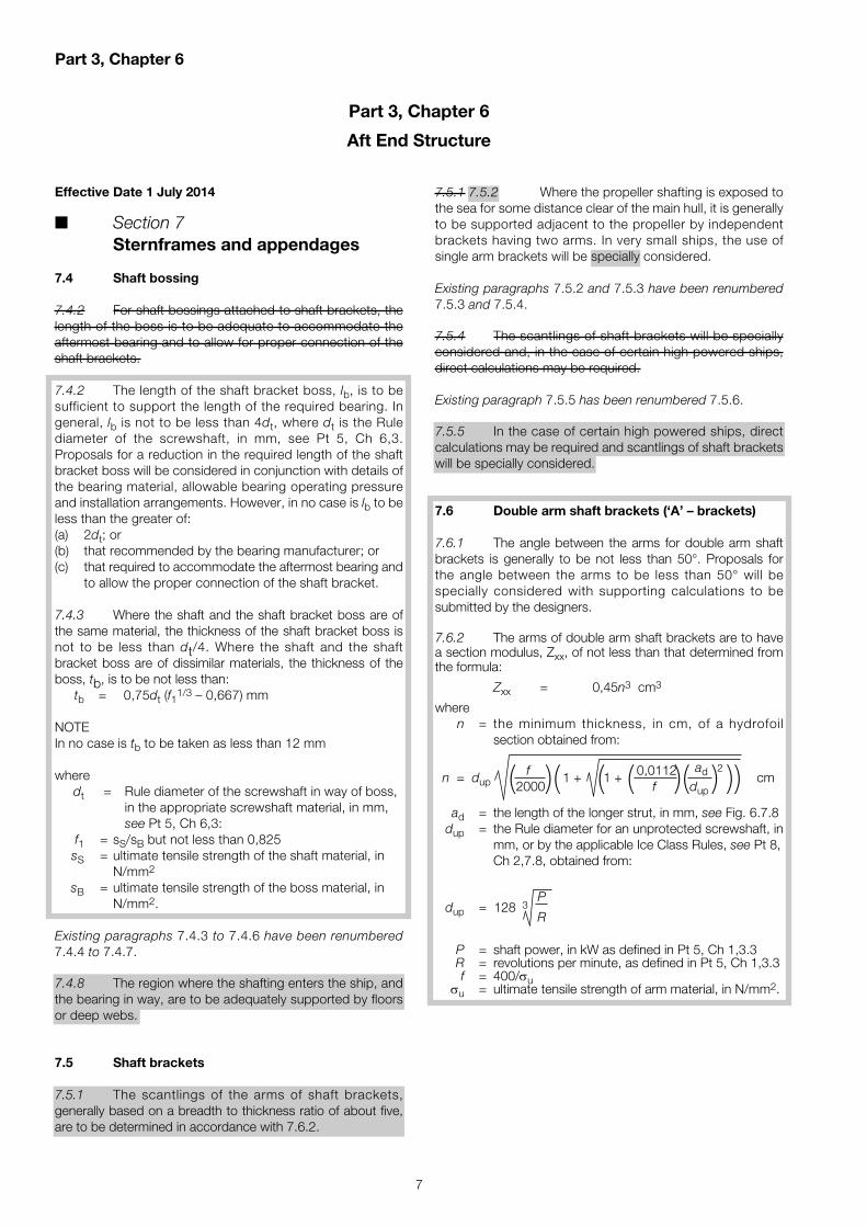
7.6.2 The arms of double arm shaft brackets are to havea section modulus, Zxx, of not less than that determined fromthe formula:
Zxx = 0,45n3 cm3
wheren = the minimum thickness, in cm, of a hydrofoil
section obtained from:
n = dup cm
ad = the length of the longer strut, in mm, see Fig. 6.7.8dup = the Rule diameter for an unprotected screwshaft, in
mm, or by the applicable Ice Class Rules, see Pt 8, Ch 2,7.8, obtained from:
dup = 128 3
P = shaft power, in kW as defined in Pt 5, Ch 1,3.3R = revolutions per minute, as defined in Pt 5, Ch 1,3.3f = 400/σu
σu = ultimate tensile strength of arm material, in N/mm2.
P
R
f 1 + 1 + 0,0112 ad 2(2000)( ( ( f )(dup ) ))
Effective Date 1 July 2014
■ Section 7Sternframes and appendages
7.4 Shaft bossing
7.4.2 For shaft bossings attached to shaft brackets, thelength of the boss is to be adequate to accommodate theaftermost bearing and to allow for proper connection of theshaft brackets.
7.4.2 The length of the shaft bracket boss, lb, is to besufficient to support the length of the required bearing. Ingeneral, lb is not to be less than 4dt, where dt is the Rulediameter of the screwshaft, in mm, see Pt 5, Ch 6,3.Proposals for a reduction in the required length of the shaftbracket boss will be considered in conjunction with details ofthe bearing material, allowable bearing operating pressureand installation arrangements. However, in no case is lb to beless than the greater of:(a) 2dt; or(b) that recommended by the bearing manufacturer; or(c) that required to accommodate the aftermost bearing and
to allow the proper connection of the shaft bracket.
7.4.3 Where the shaft and the shaft bracket boss are ofthe same material, the thickness of the shaft bracket boss isnot to be less than dt/4. Where the shaft and the shaftbracket boss are of dissimilar materials, the thickness of theboss, tb, is to be not less than:
tb = 0,75dt (f11/3 – 0,667) mm
NOTEIn no case is tb to be taken as less than 12 mm
wheredt = Rule diameter of the screwshaft in way of boss,
in the appropriate screwshaft material, in mm, see Pt 5, Ch 6,3:
f1 = sS/sB but not less than 0,825sS = ultimate tensile strength of the shaft material, in
N/mm2
sB = ultimate tensile strength of the boss material, inN/mm2.
Existing paragraphs 7.4.3 to 7.4.6 have been renumbered7.4.4 to 7.4.7.
7.4.8 The region where the shafting enters the ship, andthe bearing in way, are to be adequately supported by floorsor deep webs.
7.5 Shaft brackets
7.5.1 The scantlings of the arms of shaft brackets,generally based on a breadth to thickness ratio of about five,are to be determined in accordance with 7.6.2.
Part 3, Chapter 6
Aft End Structure

Part 3, Chapters 6 & 9
8
7.6 7.7 Propeller hull clearances
7.6.1 7.7.1 Recommended minimum clearancesbetween the propeller and the sternframe, rudder or hull aregiven in Table 6.7.5. These are the minimum distancesconsidered desirable in order to expect reasonable levels ofpropeller excited vibration. Attention is drawn to the importanceof the local hull form characteristics, shaft power, water flowcharacteristics into the propeller disc and cavitation whenconsidering the recommended clearances.
4390/192
a d
x x
Fig. 6.7.8Double arm shaft bracket
Effective Date 1 July 2014
■ Section 2Timber deck cargoes
2.1 Application
2.1.2 In other cases, proposals to carry timber deckcargoes which will impose on the weather deck a mean cargoloading in excess of 8,5 kN/m2 (0,865 tonne-f/m2) will beconsidered on the basis of these requirements. In particular,the requirements of 2.5 to 2.8 2.9 to 2.12 are to be compliedwith.
2.3 Statutory Requirements General
2.3.1 Attention is drawn to the requirements of theInternational Convention for the Safety of Life at Sea, 1974,Chapter VI, as amended, the International Load LineConvention, 1966, concerning timber deck cargoes, and its1988 Protocol, and also to National Regulations. Attention isalso drawn to IMO Resolution A.1048(27) Code of SafePractice for Ships Carrying Timber Deck Cargoes, 2011.
2.3.2 A timber deck cargo loading and lashing plan, showing the stowage and securing of the timber cargo andthe walkway/life-line arrangements, is to be submitted forapproval, and a copy placed on board the ship for the information of the Master.
Part 3, Chapter 9
Special Features
2.3.2 Timber deck cargoes are to be loaded, stowed andsecured throughout the voyage, in accordance with the CargoSecuring Manual approved by the Flag Administration asrequired by SOLAS Chapter VI.
2.3.3 Each cargo securing arrangement for timber deckcargoes detailed in the ship’s Cargo Securing Manual is to bedocumented by a lashing plan that shows the following:(a) maximum cargo weight for which the arrangement is
designed;(b) maximum stowage height;(c) required number and strength of blocking devices and
lashings, as applicable;(d) required pre-tension in lashings;(e) other cargo properties of importance for the securing
arrangement, such as friction, rigidity of timber pack-ages;
(f) illustrations of all securing items that might be used;(g) any restrictions regarding maximum accelerations,
weather criteria, restricted sea areas and for non-winterconditions only;
(h) the walkway/life-line arrangements; and(j) stowage arrangement, which is to be in accordance with
2.7.The Cargo Securing Manual is to be submitted for approval,and a copy placed on board the ship.
2.3.4 All timber deck cargoes must be compactlystowed, lashed and secured. Friction alone is not deemedsufficient and such methods are not endorsed by Lloyd'sRegister.
Part 3, Chapter 9
9
Existing paragraphs 2.3.3 to 2.3.5 have been renumbered2.3.5 to 2.3.7.
2.3.6 It is the Owner’s/Master’s responsibility to supplyloose gear (e.g., uprights, wire lashings and life-lines) in accordance with the approved timber deck cargo loading andlashing plan when the ship is carrying timber deck cargoes attimber freeboards. However, it is not a requirement that loosegear remains permanently on board a ship assigned timberfreeboards.
2.3.8 It is the Master’s responsibility to ensure loose gear(e.g., uprights, wire lashings and life-lines) are supplied andfitted onboard in accordance with the approved timber deckcargo loading and lashing plan when the ship is carryingtimber deck cargoes. However, it is not a requirement thatloose gear remains permanently on board a ship assignedtimber freeboards.
2.4 Arrangements
2.4.2 A forecastle of at least standard height of a superstructure, defined by Regulation 33 of the InternationalLoad Line Convention, as amended, and of length at least0,07L is to be fitted. In addition, in ships of less than 100 m inlength, a poop of at least standard height, or a raised quar-terdeck with a deckhouse or strong steel hood of at least thesame total height, is to be fitted.
2.5 Uprights
2.4.3 2.5.1 Uprights are to be of adequate strength butare not to exceed the strength of the bulwark. Where timberuprights are used, it is the responsibility of the Master to usetimber which is of a type and grade which has proved satis-factory for the purpose. Where a timber load line is notassigned and uprights are not connected to the bulwark,uprights are to be of adequate strength but need not relate tothat of the bulwark, see 2.1.2.
2.4.4 Where only packaged timber is to be carried,uprights may be omitted.
2.5.2 Uprights are to be used for all timber deck cargoeswith the exception that, where only packaged timber is to becarried, uprights may be omitted, depending on rackingstrength and not including uprights or stoppers (low uprights)situated either side of hatch covers.
2.4.5 2.5.3 The spacing of the uprights is to be suitablefor the length and character of the timber to be carried butshould not is not to exceed 3 m.
2.4.6 2.5.4 Each upright is to extend above the top ofthe cargo and be fitted with a strap or bracket support at thetop of the bulwark to hold it upright whilst loading.
2.4.7 2.5.5 Strong permanent bulwarks, or efficientrails of specially strong construction, are to be fitted. Steelbulwarks, along with guard rails and stanchions, are accept-able as supports for uprights, provided substantial socketsare built for each upright.
2.4.8 2.5.6 Deck sockets are to be of a size to suit the dimensions of the uprights and are to be not less than 100 mm in depth with drainage provided. They are to be efficiently connected to the hull structure. A locking pin orwedge is to be provided to prevent the upright lifting out ofthe socket.
2.6 Lashings
2.4.9 2.6.1 The timber deck cargo is to be securedalong its length by independent overall top over lashings.
2.4.10 2.6.2 The spacing of top over lashings is to bedetermined by the height of the cargo above the deck or bythe type of timber, see 2.6.3 and 2.6.4:(a) For a height not exceeding 4 m, the spacing should not
be more than 3 m.(b) For a height of 6 m and above, the spacing should not
be more than 1,5 m where the timber uprights are used.(c) At intermediate heights, the average spacing is to be
obtained by linear interpolation.(a) For heights not more than 2,5 m, the spacing is to be
not more than 3 m.(b) For heights above 2,5 m, the spacing is to be not more
than 1,5 m.
2.4.11 Lashings are to be provided 0,6 m and 1,5 m fromthe ends of timber deck cargoes where there is no end bulkhead.
2.4.12 2.6.3 Where only packaged timber is to becarried, and uprights are omitted, see 2.5.2, lashings are tobe spaced not more than 1,5 m apart.
2.4.13 Lashings are to be not less than 19 mm close linkchain, or flexible wire rope of equivalent strength, fitted withslip hooks and turnbuckles which are accessible at all times.Wire rope lashings are to have a short length of long link chainto permit the length of the lashings to be regulated.
2.6.4 Round wood timber deck cargo is to be securedthroughout its length by top over lashings spaced not morethan 1,5 m apart.
2.6.5 At the fore and aftermost ends of each continuoustimber deck stow, the spacing of the lashings determinedfrom 2.6.2, 2.6.3 or 2.6.4 is to be halved.
2.6.6 The spacing of lashings is to be such that lashingsare positioned as close as practicable to the ends of eachcontinuous timber deck stow.
2.6.7 Round wood timber deck cargo stowed over andabove hatches, in addition to 2.6.4, is to be further secured bya system of athwartship lashings connecting respective portand starboard uprights at three quarters of the height of thestow. If the height of the hatch cover over which the cargo isstowed is less than 2 m, a further athwartship lashing is to beinstalled 1 m above the hatch cover.
2.4.14 Lashings and fittings are to have a minimum SWLof 2700 kg and 2800 kg respectively. Each component is tobe proof loaded to twice the SWL, and should not show anysign of damage or deformation afterwards.
Part 3, Chapter 9
10
2.6.8 Lashings and fittings must not:(a) have a breaking strength of less than 133 kN;(b) elongate more than 5 per cent at 80 per cent of the
breaking strength;(c) show any permanent deformation at less than 40 per
cent of the breaking strength.
2.4.15 2.6.9 Where timber is in lengths of less than 3,6 m,the spacing of lashings is to be reduced, or other suitable provisions made to suit the length of the timber.
2.6.10 Open hooks, which may loosen if the lashingbecomes slack, are not to be used in securing arrangementsfor timber deck cargoes and web lashing is not to be used incombination with chain or wire lashing.
2.6.11 Slip hooks or other appropriate methods may beused for quick and safe adjustment of lashings. Pelicanhooks, when used, are to be moused.
2.6.12 Corner protectors are to be used to prevent lashingsfrom cutting into the cargo and to protect lashings fromdamage at sharp corners.
2.6.13 Every lashing is to be provided with a tighteningdevice or system, situated so that it can be safely and efficientlyoperated when required. The magnitude of the componentsof the resolved load produced by the tightening device orsystem is not to be less than:(a) 27 kN in the horizontal; and(b) 16 kN in the vertical.
2.6.14 Once the lashings are secured, the tighteningdevice or system is to have not less than half the tighteningcapacity available for further use.
2.6.15 If wire rope clips are used to make a joint in a wirelashing, the following conditions are to be observed to avoida significant reduction in strength:(a) the number and size of rope clips utilised are to be in
proportion to the diameter of the wire rope and no fewerthan three, each spaced at intervals of not less than 150 mm.
(b) the saddle portion of the clip is to be applied to the liveload segment; and
(c) rope clips are to be initially tightened so that they visiblycompress the wire rope and are subsequently to be re-tightened after the lashing has been stressed.
2.6.16 Bulldog grips are only suitable for a standard wirerope of right-hand lay having six strands. Such grips are not tobe used for wire rope of left-hand lay or different construction.
2.6.17 Rounded angle pieces of suitable material anddesign are to be used along the upper outboard edge of thestow to bear the stress and permit free reeving of the lashings.
2.4.16 2.6.18 Eye plates are to be of substantialconstruction, effectively connected to the hull structure, andplaced at intervals determined from 2.4.10, 2.4.11 or 2.4.122.6.2 to 2.6.5. The distance from a superstructure end bulkheadto the first eye plate and lashing is to be not more than 2 m.
2.7 Stowage
2.7.1 The stowage arrangements are to be detailedwithin the lashing plan, see 2.3.3.
2.7.2 Timber deck cargoes are to extend over at least theentire available length, which is the total length of the well orwells between superstructures. Where there is no limitingsuperstructure at the after end, the timber is to extend at leastto the after end of the aftermost hatchway.
2.7.3 The timber deck cargo is to extend athwartships asclose as possible to the ship’s side, due allowance beingmade for obstructions, provided any gap thus created at theside of the ship does not exceed a mean of four per cent ofthe breadth.
2.7.4 The timber is to be stowed as solidly as possible toat least the standard height of a superstructure other than araised quarter deck. It is not to interfere in any way with thesafe navigation and necessary work of the ship.
2.7.5 On a ship within a seasonal winter zone in winter,the height of the deck cargo above the deck exposed toweather must not exceed one third of the extreme breadth ofthe ship.
2.7.6 Cargo which overhangs hatch coamings or otherstructures in the longitudinal direction by more than a third oftheir individual or packed length is to be supported at theouter end by other cargo stowed on deck or by structure ofadequate strength.
2.8 Safety arrangements
2.4.17 A walkway is to be provided over the timber deckcargo. This walkway is either to be:(a) At, or near, the centreline of the ship, consisting of two
sets of guard wires, spaced 1 m apart, each with threecourses of wires, the lower spaced at 230 mm and theremainder at 380 mm. Stanchions are to be not morethan 3 m apart, and these are to be secured to thetimber cargo by spikes, or other equivalent means. Apolypropylene net, with a mesh not greater than 230 mm x 230 mm, in conjunction with stanchions andtop and bottom wires, may also be accepted, or
(b) where the timber uprights are taken up 1 m above thetop of the timber cargo, three courses of guard wiresspaced not more than 350 mm apart, secured to theuprights from forward to aft, port and starboard, with asingle wire life-line fitted at the centreline of the shipadequately supported by stanchions spaced not morethan 10 m apart.
2.8.1 If there is no convenient passage on or below thedeck of the ship, a walkway is to be provided over the timberdeck cargo. This walkway is either to be:(a) At, or near, the centreline of the ship, consisting of two
sets of guard wires, spaced 1 m apart, each with morethan three courses of wire. The opening below thelowest course is not to exceed 230 mm; the remainingcourses are to be spaced not more than 380 mm apartto a height of at least 1 m above the timber deck cargo.
Part 3, Chapters 9 & 11
11
The guard wires are to be secured to stanchions. Thestanchions are to be not more than 3 m apart, and theseare to be secured to the timber cargo by spikes, or otherequivalent means.
(b) Alternatively, where uprights are used, guard wires,spaced vertically not more than 330 mm apart, are to besecured to the uprights along the length of the timberdeck cargo on both port and starboard sides to a heightof not less than 1 m above the cargo. A wire life-line isalso to be fitted at the centreline of the ship, adequatelysupported by stanchions spaced not more than 10 mapart.
A safe walking surface, not less than 600 mm in width, is to befitted over the cargo and effectively secured to the top of it inline with the walkway or adjacent to the life-line. All lines are tobe taut using tightening devices.
2.4.18 2.8.2 Safe access is to be provided from to thetop of the timber deck cargo to poop and forecastle decks bymeans of properly constructed ladders, steps or ramps fittedwith guard lines or handrails.
Existing paragraphs 2.4.19 and 2.4.20 have been renumbered 2.8.3 and 2.8.4.
2.4.21 The timber deck cargo is to extend athwartships asclose as possible to the ship’s side, due allowance beingmade for obstructions provided any gap thus created at theside of the ship does not exceed a mean of four per cent ofthe breadth.
2.4.22 The timber is to be stowed as solidly as possible toat least the standard height of a superstructure other than araised quarter deck.
Subsequent sub-sections 2.5 to 2.8 have been renumbered2.9 to 2.12.
Effective Date 1 July 2014
■ Section 2Steel hatch covers
2.4 Allowable stress and deflection
2.4.2 The vertical deflection of primary supportingmembers due to the vertical weather design load accordingto 2.3.2, or cargo loads according to 2.3.4, 2.3.5 and Pt 4,Ch 8,11.2, is to be not more than 0,0056lg where lg is thegreatest span of primary supporting members.For 'tween deck hatch covers not exposed to the verticalweather design load according to 2.3.2, the vertical deflectionof primary supporting members due to the cargo loadsaccording to 2.3.4, 2.3.5 and Pt 4, Ch 8,11.2 is to be notmore than 0,007lg where lg is the greatest span of primarysupporting members.
Part 3, Chapter 11
Closing Arrangements for Shell, Deck and Bulkheads
Part 3, Chapters 12 & 16
12
Cd = shape coefficient (0,5 for pipes,1,3 for air pipe orventilator heads in general and 0,8 for an air pipe orventilator head of cylindrical form with its axis in thevertical direction)
Cs = slamming coefficient (3,2)Cp = protection coefficient (0,7 for pipes and ventilator
heads located immediately behind a breakwater orforecastle and 1,0 elsewhere and immediatelybehind a bulwark).
5.2.2 Forces acting in the horizontal direction on the pipeand its closing device may be are to be not less than thosecalculated from 5.2.1 using the largest projected area of eachcomponent.
Effective Date 1 July 2014
■ Section 5Air pipes, ventilator pipes andtheir securing devices located onthe exposed fore deck
5.2 Loading
5.2.1 The pressures, p, in kN/m2 acting on air pipes, ventilator pipes and their closing devices may be calculatedfrom: The design pressure acting on air pipes, ventilator pipesand their closing devices is to be taken as not less than:
p = 0,5ρ V2 Cd Cs Cp kN/m2
whereρ = density of sea-water (1,025 t/m3)V = velocity of water over the fore deck (13,5 m/sec)
= 13,5 m/sec for d ≤ 0,5d1
= 13,5 2 1– for d > 0,5d1( )d = distance from summer load waterline to exposed
deckd1 = 0,1L but need not be taken as greater than 22 m
dd1
Part 3, Chapter 12
Ventilators, Air Pipes and Discharges
Effective Date 1 July 2014
■ Section 2Structural design assessment
2.1 Structural Design Assessment notation – SDA
2.1.2 This procedure is mandatory, and additional tonormal Rule structural design approval, for:(a) bulk carriers and oil tankers without a CSR notation
(see 1.1.1) greater than 190 m in length;(b) container ships with a beam greater than 32 m; of
Panamax size or greater;(c) The primary structure of LNG ships;(d) The primary structure of Type A LPG ships:(e) Other ships of Type B and C where the type, size and
structural configuration demand;(f) passenger ships where it is considered that the super-
structure will be subjected to a significant load fromflexure of the hull girder; or, where it is required to utilisethe load carrying capability of the superstructure forlongitudinal strength; and
(g) other ships where type, size and structural configurationdemand, see also Pt 1, Ch 2,2.3 and Ch 2,2.7.
Part 3, Chapter 16
ShipRight Procedures for the Design, Construction and Lifetime Care of Ships
Part 4, Chapters 2 & 5
13
= 5 knots, for all other ship typesEffective Date 1 July 2014
■ Section 4Shell envelope plating
4.2 Bow flare and wave impact pressures
(Parts only shown)4.2.1 This Section is applicable to:(a) bow flare region;(b) sides and undersides of sponsons; and(c) other parts of the side shell plating close to and above
the design waterline that are expected to be subjected towave impact pressures.
V = speed, in knots
for ≥ 0,5
= is to be taken as the maximum service speed, inknots, as defined in Pt 3, Ch 1,6. For passengeryachts not required to maintain high speeds insevere weather, the value of V may be speciallyconsidered, but is not to be taken as less than thegreater
of or 5 knots. Where V has been specially
considered it is to be noted in the classificationrecords as a memorandum that should state: “Adesign speed of … knots has been used for theassessment of bow structure with regards to bowflare impacts. It should be noted that this speedmay not be appropriate for all conditions and it isthe responsibility of the Master to apply goodSeamanship to minimise bow flare slamming.”
for < 0,5
= 0 knots, for passenger ships
xL
V3
xL
Part 4, Chapter 2
Ferries, Roll on-Roll off Ships and Passenger Ships
Effective Date 1 July 2014
■ Section 8Void spaces
8.1 Void spaces on unmanned pontoonsnot fitted with auxiliary machinery
8.1.1 Drainage arrangements and air pipes are to beprovided in accordance with Pt 5, Ch 13,10 and Pt 5, Ch13,12.4.4 respectively.
Part 4, Chapter 5
Barges and Pontoons
8.1.2 Deck openings to allow drainage in accordancewith Pt 5, Ch 13,10.1.3 are to be as small as practicable andclosed by watertight gasketed covers of steel or equivalentmaterial.
3.2 Longitudinal strength
3.2.1 Longitudinal strength calculations are to be madein accordance with the requirements of Pt 3, Ch 4 and theadditional notes contained in this Section and Section 14.
3.2.2 The design vertical wave bending moments anddesign wave shear forces are to be determined in accordancewith Ch 2,2.4 and Ch 2,2.5 and are to be used in Pt 3, Ch 4.
3.2.3 The values of sagging ffS and hogging ffH correctionfactors due to non-linear effects of the hull shape are to bederived by non-linear ship motion analysis based on equivalentdesign sea state methods where the following conditionapplies:
L > 300 m and one or more of (i) |ffS|> 1,4 or(ii) RABF > 0,2 or(iii) RABFU > 0,2
whereffS and ffH are defined in Ch 2,2.4.1RABF is the bow flare area ratio for the lower region
just above the still waterline
= ( )RABFU is the bow flare area ratio for the upper region
near the deck
= ( )ABF, BWL are defined in Ch 2,2.4.1ABFU is the bow flare area in m2 for the region from a
waterline of TC,U to TC,2U, calculated in the sameway as ABF see Ch 2, 2.4.1
TC,2U = T + C1 m or the local deck edge height if thisis lower
C1 is defined in Table 4.5.1 in Pt 3, Ch 4The methodology to calculate the non-linear ship motion waveloads is given in LR’s ShipRight Procedure Guidance Noteson the Assessment of Global Design Loads of LargeContainer Ships and Other Ships Prone to Whipping andSpringing.
3.3 Combined longitudinal and torsional strength
3.3.1 The strength of the ship to resist a combination oflongitudinal and torsional loads is to be determined in accordancewith 15.1.
ABFU
0,1LBWL
ABF
0,1LBWL
Part 4, Chapter 8
14
Effective Date 1 July 2014
■ Section 1General
1.1 Application and definitions
1.1.2 The term ‘Panamax’ container ship is as defined inLloyd’s Register’s (hereinafter referred to as ‘LR’) ShipRightSDA Procedures Manual Primary Structure of ContainerShips.
Existing paragraphs 1.1.3 and 1.1.4 have been renumbered1.1.2 and 1.1.3.
1.1.5 1.1.4 For container ships with a beam ofPanamax size or greater than 32 m , or where the structuralarrangements are considered such as to necessitate it, theShipRight notations SDA and CM are mandatory, see 1.3 andSection 14.
Existing paragraphs 1.1.6 and 1.1.7 have been renumbered1.1.5 and 1.1.6.
1.3 Class notations
1.3.3 The notations SDA and CM are mandatory forcontainer ships with any of the following features:(a) beam of a Panamax size or greater than 32 m;(b) narrow side structures;(c) abnormal hull form; or(d) unusual structural configuration or complexity.
Existing Section 3 has been deleted in its entirety.
■ Section 3Longitudinal strength
3.1 General
3.1.1 Longitudinal strength calculations are to be carriedout in accordance with 3.2 and 3.3.
3.1.2 Alternatively the values and distributions of waveinduced loads may be derived by direct calculation in accordancewith LR’s ShipRight Procedure Guidance Notes on theAssessment of Global Design Loads of Large Container Shipsand Other Ships Prone to Whipping and Springing.
3.1.3 For ships of abnormal hull form, or for ships ofunusual structural configuration or complexity, the values anddistributions of wave induced loads are to be agreed with LR.
Part 4, Chapter 8
Container Ships
Part 4, Chapter 8
15
Existing Section 14 has been deleted in its entirety.
■ Section 14Direct calculation
14.1 Procedures for calculation of combinedlongitudinal and torsional strength
14.1.1 For container ships as defined in 1.3.3(b), (c) and(d) or with beam greater than 33 m, longitudinal strengthcalculations are to be made in accordance with Parts A and Bof LR’s ShipRight SDA Procedure for container ships, see alsoTable 8.14.1.
14.1.2 The global, primary and local structure scantlingsare to be assessed using the vertical and horizontal wavebending moments and shear forces and torsional wavemoments derived using non-linear ship motion analysis basedon equivalent design sea state methods where one or more ofthe following conditions applies:(a) B > 60 m(b) L > 350 m The methodology to calculate the non-linear ship motion waveloads is given in LR’s ShipRight Procedure Guidance Noteson the Assessment of Global Design Loads of LargeContainer Ships and Other Ships Prone to Whipping andSpringing.
14.2 Procedures for verification of primarystructure scantlings
14.2.1 For container ships as defined in 1.3.3, the strengthof the ship’s primary structure scantlings of double bottom,side and transverse bulkheads is to be assessed in accordancewith Part C of LR’s ShipRight SDA Procedure for containerships. The wave loads to be applied in this assessment are tobe calculated in accordance with 3.2.
14.2.2 For other container ships the method for analysis ofprimary structure of double bottom, side structure and transversebulkheads is to be agreed with LR.
14.3 Procedures for verification of structuralresponse due to whipping, springing andfatigue
14.3.1 The ultimate strength of the hull girder of containerships is to be assessed against the extreme wave bendingmoments including whipping and wave impact loads in accor-dance with LR’s ShipRight Procedure Guidance Notes on theAssessment of Global Design Loads of Large Container Shipsand Other Ships Prone to Whipping and Springing where oneor more of the following conditions applies:(a) L > 350 m(b) L > 300 m and one or more of
(i) |ffS|> 1,4 or(ii) RABF > 0,2 or(iii) RABFU > 0,2
(c) Use of HT47 or above for the deck or hatch side coaming(d) Use of HT36 or above for the bottom shell
whereffS is defined in Ch 2, 2.4.1RABF and RABFU are defined in 3.2.3See Table 8.14.1.
14.3.2 The fatigue assessment of container ships includinghull girder springing is to be assessed where one or more ofthe following conditions applies, see Table 8.14.1:(a) L > 350 m(b) L > 250 m and fc > fsp(c) Use of HT47 or above for the deck or hatch side coaming(d) Use of HT36 or above for the bottom shellwhere
fc is a wave encounter frequency at which it isexpected that springing will become important
= 1 + Hz( )fsp is the natural frequency of the 2 node hull girder
vertical bending mode in Hz. This can be veryapproximately calculated as:
= Hz( ) V = speed in knots as defined in Pt 3, Ch 1,6.1.10E = Young's modulus in N/mm2
= 206000 N/mm2 for steelI is the midship moment of inertia in m4, see Pt 3, Ch 4
Td is the design (normal standard operating) draught, inmetres
Cb, L, and B are given in Pt 3, Ch 1,6.The fatigue assessment is to be carried out in accordancewith LR’s ShipRight Procedure Guidance Notes on theAssessment of Global Design Loads of Large Container Shipsand Other Ships Prone to Whipping and Springing, which alsomakes reference to LR’s ShipRight FDA procedures.
EI105
1,8 B Td Cb
1,1πL2
1,4V2g
1,42π

Part 4, Chapter 8
16
Existing Section 15 has been deleted in its entirety.
■ Section 15Combined stress calculations
15.1 Application
15.1.1 The combined stresses due to vertical bendingmoment, horizontal bending moment and torque are to becalculated as described in this Section.
15.2 Symbols and definitions
15.2.1 The following symbols and definitions are applicableto this Section unless otherwise stated:
ZY = actual hull section modulus about the transverseneutral axis at the position considered, in m3
ZZ = actual hull section modulus about the verticalneutral axis at the position considered, in m3
ε = maximum shear centre distance below baseline ofthe ship in the midship region, in metres. ε is takenas positive where the shear centre is below thebaseline
Ms = design still water bending moment at the sectionunder consideration, in kN m (tonne-f-m)
σc = combined stress at the position considered.
15.3 Design loadings
15.3.1 The design vertical wave bending moment, MWC,at any position along the ship is defined as:MWC = 0,0505C1 L2 B (Cb + 0,7) C3 kN m
= (0,0052C1 L2 B (Cb + 0,7) C3 tonne-f m)C3 = vertical wave bending moment distribution coefficient
depending on the length Lpp as defined in Table 8.15.1
C1 is given in Table 4.5.1 in Pt 3, Ch 4.L, B, Cb are given in Pt 3, Ch 1,6.The sign convention is given in Fig. 8.15.1.
15.3.2 The design horizontal wave bending moments,MHC1 and MHC2, at any position along the ship are defined as:MHC1 = 0,2063C1 C41 L2 T (Cb + 0,7) kN m
= (0,0210C1 C41 L2 T (Cb + 0,7) tonne-f-m)MHC2 = 0,2063C1 C42 L2 T (Cb + 0,7) kN m
= (0,0210C1 C42 L2 T (Cb + 0,7) tonne-f-m)
Table 8.14.1 Summary of direct calculation analysis requirements for container ships
Application criteria. If any of the following criteria apply then the appropriate analysis is required
Rule requirement Rule ShipRight Length Any of fc > fsp Deck or Bottom steel BreadthSee Note 1 reference notation criteria |ffS| > 1,4 hatch side grade criteria
or coaming >= HT36RABF > 0,2 steel grade
or >= HT47RABFU > 0,2
Part C of LR’s ShipRight SDA Procedure for 1.1.5 SDA — — — — — B > 32container ships
Parts A and B of LR’s ShipRight SDA Procedure 14.1.1 SDA — — — — — B > 33for container ships
Non-linear ship motionanalysis to calculate 3.2.3 — — L > 300 — — — —hogging and sagging factors
Non-linear ship motion analysis to calculate combined vertical, 14.1.2 — L > 350 — — — — B > 60horizontal and torsionalloads
Fatigue assessment 14.3.2 FDA L > 350 — L > 250 Yes Yes —(see Note 3)
Whipping assessment 14.3.1 — L > 350 L > 300 — Yes Yes —
Springing assessment 14.3.2 — L > 350 — L > 250 Yes Yes —See Note 2
NOTES1 The stated rule requirements may be deemed applicable to ships that do not meet the application criteria but where the structural
configuration is such as to necessitate them.2 The results of the springing assessment may also need a fatigue assessment procedure to be undertaken.3 If ShipRight notation FDA is to be assigned, the requirements of LR’s ShipRight FDA procedure are to be complied with; this may require
calculations additional to those implied by 14.3.2.
Part 4, Chapter 8
17
C41, C42 = horizontal wave bending moment distribution coefficient depending on the length, Lpp, as defined in Table 8.15.2
C1 is given in Table 4.5.1 in Pt 3, Ch 4L, B, T, Cb are given in Pt 3, Ch 1,6.The sign convention is given in Fig. 8.15.1.
15.3.3 The design hydrodynamic torques, MWTC1 andMWTC2, at any position along the ship are defined as:MWTC1 = MWTCB1 + MWTCQ1MWTCB1 = 0,0764C1 C51 L B2 (Cb + 0,7) kN m
= (0,0078C1 C51 L B2 (Cb + 0,7) tonne-f-m)MWTCQ1 = –(0,65T + f3 ε) QHC1 kN m (tonne-f-m)MWTC2 = MWTCB2 + MWTCQ2MWTCB2 = 0,0764C1 C52 L B2 (Cb + 0,7) kN m
= (0,0078C1 C52 L B2 (Cb + 0,7) tonne-f-m)MWTCQ2 = –(0,65T + f3 ε) QHC2 kN m (tonne-f-m)C51, C52 = hydrodynamic torque distribution coefficientdepending on the length, Lpp, as defined in Table 8.15.2C1 is given in Table 4.5.1 in Pt 3, Ch 4
f3 = shear centre distribution factor, to be taken as:–1,0 at the aft end of Lpp1,0 between 0,15Lpp and 0,80Lpp from aft–1,0 at the forward end of Lpp
Intermediate values are to be determined by linear interpolation:QHC1 = 0,8683C1 K31 L T (Cb + 0,7) kN
= (0,0886C1 K31 L T (Cb + 0,7) tonne-f)QHC2 = 0,8683C1 K32 L T (Cb + 0,7) kN
= (0,0886C1 K32 L T (Cb + 0,7) tonne-f)K31, K32 = horizontal wave shear force distribution coefficient
depending on the length, Lpp, as defined in Table 8.15.2
L, B, T, Cb are given in Pt 3, Ch 1,6.ε is given in 15.2.1The sign convention is given in Fig. 8.15.1.
Positive vertical bending moment
Positive horizontal bending moment
Positive horizontal shear force
Positive torsional moment
(+)
(+)
X
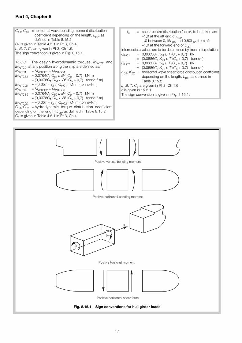
Fig. 8.15.1 Sign conventions for hull girder loads
Part 4, Chapter 8
18
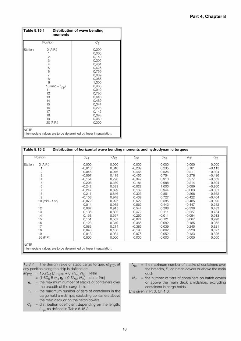
15.3.4 The design value of static cargo torque, MSTC, atany position along the ship is defined as:MSTC = 15,7C6 B (ηs ηt + 0,7Nsd Ntd) kNm
= (1,6C6 B (ηs ηt + 0,7Nsd Ntd) tonne-f/m)ηs = the maximum number of stacks of containers over
the breadth of the cargo holdηt = the maximum number of tiers of containers in the
cargo hold amidships, excluding containers abovethe main deck or on the hatch covers
C6 = distribution coefficient depending on the length,Lpp, as defined in Table 8.15.3
Nsd = the maximum number of stacks of containers overthe breadth, B, on hatch covers or above the maindeck
Ntd = the number of tiers of containers on hatch coversor above the main deck amidships, excludingcontainers in cargo holds
B is given in Pt 3, Ch 1,6.
Position C3
Station 0 (A.P.) 0,0001 0,0652 0,1593 0,3054 0,4645 0,6266 0,7697 0,8898 0,9669 1,000
10 (mid – Lpp) 0,98811 0,91912 0,79613 0,64814 0,48915 0,34416 0,22517 0,14218 0,09319 0,06020 (F.P.) 0,000
NOTEIntermediate values are to be determined by linear interpolation.
Table 8.15.1 Distribution of wave bending moments
Table 8.15.2 Distribution of horizontal wave bending moments and hydrodynamic torques
Position C41 C42 C51 C52 K31 K32
Station 0 (A.P.) 0,000 0,000 0,000 0,000 0,000 0,0001 –0,016 0,010 –0,289 0,235 0,101 –0,1132 –0,046 0,046 –0,456 0,525 0,211 –0,3043 –0,097 0,119 –0,455 0,754 0,276 –0,4864 –0,154 0,228 –0,342 0,910 0,277 –0,6595 –0,208 0,369 –0,184 0,988 0,214 –0,8046 –0,242 0,533 –0,022 1,000 0,089 –0,8607 –0,247 0,699 0,169 0,944 –0,083 –0,8018 –0,217 0,846 0,323 0,851 –0,268 –0,6629 –0,153 0,948 0,439 0,727 –0,422 –0,404
10 (mid – Lpp) –0,072 0,997 0,522 0,585 –0,485 –0,09011 0,014 0,985 0,562 0,443 –0,447 0,23212 0,087 0,915 0,544 0,288 –0,338 0,48313 0,136 0,802 0,472 0,111 –0,227 0,73414 0,158 0,657 0,260 –0,011 –0,094 0,91315 0,151 0,502 –0,074 –0,121 0,067 0,99816 0,123 0,349 –0,366 –0,082 0,185 0,95217 0,083 0,214 –0,385 0,039 0,245 0,82118 0,043 0,106 –0,198 0,062 0,220 0,62719 0,013 0,034 –0,075 0,052 0,133 0,32620 (F.P.) 0,000 0,000 0,000 0,000 0,000 0,000
NOTEIntermediate values are to be determined by linear interpolation.

Part 4, Chapter 8
19
15.4 Combined stresses
15.4.1 Combined stress calculations are to be carried outat least at the following positions along the length of the ship:(a) At the forward and aft ends of the engine room.(b) At the forward and aft ends of the deck-house for
multi-island designs.(c) At the forward and aft transverse bulkhead positions of
each cargo bay.(d) At the forward and aft transverse bulkhead of fuel oil
deep tanks.(e) At any other sections where there are significant
changes in cross-section properties.
15.4.2 The combined stress, σc, is to be taken as σchog,calculated as:
σchog = (σHC1 + σWTC1)2 + (σHC2 + σWTC2)2 + |ffH σWC| + |σSTC| + |σSC|
σSC = longitudinal stress due to hogging or sagging design still water bendingmoment Ms
σWC = longitudinal stress due to vertical wave bending moment
σHC1, σHC2 = longitudinal stress due to horizontal wave bending moment
σSTC = warping stress due to static cargo torqueσWTC1, σWTC2 = warping stress due to hydrodynamic torque
ffH = hogging vertical bending moment correc-tion factor calculated in accordance with Ch 2,2.4
other symbols are as defined in 15.3 and 15.4.
15.4.3 For ships with a beam greater than or equal to 33 m,longitudinal stresses are to be calculated using a finiteelement model of the entire hull in accordance with Part A ofthe LR’s ShipRight SDA procedure for container ships.
15.4.4 For ships with a beam less than 33 m, the longitudinal stresses may be obtained as follows:
σSC = x 10–3 N/mm2 (kgf/mm2)
σWC = x 10–3 N/mm2 (kgf/mm2)
σHC1 = C7 x 10–3 N/mm2 (kgf/mm2)
σHC2 = C7 x 10–3 N/mm2 (kgf/mm2)MHC2
ZZ
MHC1
ZZ
MWC
Zy
Ms
Zy
σWTC1, σWTC2 and σSTC are to be evaluated by approvedcalculation procedures.
C7 = coefficient for shear lag depending on vertical locationof the point under consideration
= 0,6 at inboard edge of strength deck= 1,0 at base line= intermediate positions by interpolation
Zy and Zz are given in 15.2.1.
15.4.5 At each section the stresses are to be calculatedon the port and starboard sides, at:(a) the inboard edge of the strength deck;(b) the point on the bilge where the combined stress is
greatest; and(c) the top of continuous hatch coaming (where fitted).
15.4.6 Where the ship’s length is greater than 350 m orthe ship’s beam is greater than 60 m, the vertical wavebending moments, horizontal wave bending moments andhydrodynamic torques are to be obtained from a directcalculation method. Alternatively, the hull stresses may beobtained using a probabilistic approach response-basedanalysis method considering the ship’s responses in waveenvironment. The analysis method is to be agreed with LR.
15.5 Permissible stress
15.5.1 The maximum tensile or compressive combinedstress σc at any position along the length is not to be morethan indicated in Table 8.15.4.
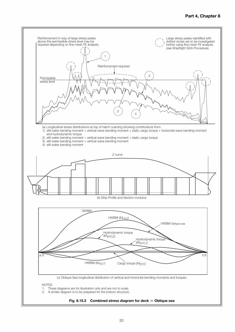
15.5.2 The assessment of combined stress mayconveniently be presented in the form of combined stressdiagrams as indicated in Fig. 8.15.2.
Position Factor C6
Station 0 (A.P.) 0,05 1,0
15 1,020 (F.P.) 0,0
NOTEIntermediate values are to be determined by linear interpolation.
Table 8.15.3 Static cargo torque distribution factor
Position Permissible combined stress,N/mm2 (kgf/mm2)
Shear strake, upper deck, top strake of longitudinal bulkheads, longitudinal hatch coaming sideand top
Elsewhere
Table 8.15.4 Permissible stress
σc = ( )190kL
19,37kL
σc = ( )17,84
kL
175kL
Part 4, Chapter 8
20
Permissiblestress level
Large stress peaks identified withdotted circles are to be investigatedfurther using fine mesh FE analysis(see ShipRight SDA Procedure).
Reinforcement required
Reinforcement in way of large stress peaksabove the permissible stress level may berequired depending on fine mesh FE analysis.
NOTES1. These diagrams are for illustration only and are not to scale.2. A similar diagram is to be prepared for the bottom structure.
Z curve
SWBM
HWBM (MHC2)
VWBM Oblique sea
Hydrodynamic torque(MWTC1)
Hydrodynamic torque(MWTC2)
HWBM (MHC1) Cargo torque (MSTC)
A.P. F.P.
1
2
34
(b) Ship Profile and Section modulus
(a) Longitudinal stress distributions at top of hatch coaming showing contributions from:1) still water bending moment + vertical wave bending moment + static cargo torque + horizontal wave bending moment and hydrodynamic torque2) still water bending moment + vertical wave bending moment + static cargo torque3) still water bending moment + vertical wave bending moment4) still water bending moment
(c) Oblique Sea longitudinal distribution of vertical and horizontal bending moments and torques
Fig. 8.15.2 Combined stress diagram for deck — Oblique sea
Part 4, Chapter 9 & Part 7, Chapter 3
21
■ Section 4Fire protection
4.2 Water spray systems
4.2.4 The system is to may be divided into sections, sothat it will be possible to close enable the closing down ofthose sections covering surfaces which are not exposed toradiant heat.
Effective Date 1 July 2014
■ Section 12Cargo temperatures
12.4 Low temperature cargoes
12.4.1 The hull structural and engineering systems permitcargoes to be loaded down to –10°C. For temperaturesbelow –10°C, hull structural assessment through temperaturedistribution and thermal stress calculations, as well asengineering systems analysis for the cargo lines/tanks andany precautions taken to minimise thermal shock or effectson associated systems (e.g., IG system), are to be provided.In addition, the cargo tank coating protection at lowtemperatures is to be confirmed, see 2.4. For lowtemperature operations, see also Part 8 and the ProvisionalRules for the Winterisation of Ships.
Part 4, Chapter 9
Double Hull Oil Tankers
Effective Date 1 July 2014
■ Section 3Fire-extinguishing
3.1 Water monitors
3.1.4 Means are to be provided for preventing the monitorjets from impinging on the ship’s structure and equipmentwhen in external fire-fighting mode. Combined systems forhigh pressure external fire fighting and deck foam fire fightingmay be permitted provided consideration is given to monitorposition and to the safety of operating pressures when used indeck foam mode and during changeover between modes.Changeover between modes is to be by a simple operatoraction. The combined system is to be capable of simple andrapid operation in either mode.
Part 7, Chapter 3
Fire-fighting Ships

Part 8, Chapter 2
22
12.1.2 The assignment of the notation Icebreaker(+) is inaddition to the requirements of Section 10 and Section 11 andis assigned in addition to the ice class notations given in Table2.1.1. See 1.5.
12.2 Operational profile
12.2.1 The operational profile(s) to be used for the basis ofassignment of the notation Icebreaker(+), as selected from12.4, is to be provided and indicated on the midship sectionsis to be derived from the icebreaker’s function, as selectedfrom 12.4.
12.2.2 Alternative operational profiles from the typicaloperational profiles, as given in 12.4, are to be determined inaccordance with 12.6 and submitted.
12.2.3 12.2.2 The operational profile is only used toselect a design basis. It is the responsibility of the Ownerand/or Builder to select determine the appropriate operationalprofile of the icebreaker.
12.3 Information to be submitted
12.3.1 For assignment of the notation Icebreaker(+), theoperational profile information is envelope criteria are to besubmitted, which may include the following information,where applicable:(a) the level icebreaking capability, in terms of speed and ice
thickness;(b) the turning capability in level ice, in terms of diameter and
ice thickness; and(c) the ramming capability, in terms of speed and ice
condition; and.(d) an ice pressure plan that indicates the design ice pressure
used for the determination of the hull structure.
12.3.2 In addition to the information submitted in 12.3.1, ascenario document, which is design specific, is required todocument the operational profile and is to include details ofthe scenarios selected for deriving and applying ice loads.
12.3.3 The scenario document is to address therequirements in Sections 10 and 11 and provide justificationfor deviation from those requirements.
12.3.4 The fol lowing is to be contained within thesubmitted scenario document:(a) icebreaker function;(b) details of ice conditions assumed;(c) operational scenarios for hull and propulsion machinery;(d) identification of critical hull and propulsion machinery
scenarios;(e) description of propulsion machinery and/or hull loading
areas with reasons for selection;(f) proposed strengthening standards for each load area;(g) arrangement of propulsion devices;
Effective Date 1 July 2014
■ Section 1Strengthening requirements fornavigation in ice – Application ofrequirements
1.1 Additional strengthening
1.1.4 The vertical extent of the ice strengthening is relatedto the ice light and ice load waterlines, which are defined in2.2. The maximum and minimum draughts at both the fore,amidships and aft ends (for the lowest ice class) will be statedon the Certificate of Class.
■ Section 2General hull requirements fornavigation in ice – All Ice Classes
2.1 General
2.1.10 To prevent unintended contact and permit closetow operations, provision of a bow ice knife (plate fittedbetween stem and bulbous bow) is not recommended forships intended to navigate with icebreaker escort.
■ Section 6Hull requirements for first-year iceconditions – Ice Classes 1AS FS,1A FS, 1B FS, 1C FS and 1D
6.4 Stem
6.4.1 The stem is to be made of rolled, cast or forgedsteel or of shaped steel plates. A sharp edged stem, asshown in Fig. 2.6.1, improves the manoeuvrability of the shipin ice. Where a sharp angle stem is fitted, the section modulusas given in 6.4.2 and 6.4.3 is to apply to the stem sectiononly, otherwise the section modulus may be applied includingside plates.
■ Section 12Requirements for Icebreaker(+)
12.1 Scope
12.1.1 Where the notation Icebreaker(+) is assigned, thearrangement, powering and dimensions of the hull structureand propulsion machinery are to be determined based on theoperational profile selected that corresponds to that whichthe icebreaker is envisaged to undertake.
Part 8, Chapter 2
Ice Operations – Ice Class

Part 8, Chapter 2
23
12.5 General arrangement
12.5.1 Consideration is to be given to the protection offuel tanks and other tanks with harmful substances, both interms of thermal insulation and ice impact protection. Adouble bottom and double side tanks are to be fitted asspecified in Pt 4, Ch 9,1.2.17. However, double side tanksmay not be required for small icebreakers (typically less than60 m), nor complete double bottom height in way of complexhullform arrangements in the fore and aft ends or heelingtanks.
12.5.2 Consideration is to be given to minimise transomsterns, as these hinder the icebreaker’s ability to back in ice,and in particular the navigation of ice ridges. A transom sternshould not normally extend below the Upper Ice Waterline.Where this cannot be avoided, the transom should be kept asnarrow as possible and the scantlings of plating and stiffenersare to be as required for the stern section.
12.5.3 The requirements are based on an effectiveicebreaker bow form. Icebreaking angles vary depending onthe icebreaking form; however, in general, the bow stemangle is not to be greater than 45°, and the bow waterlineangle not greater than 40°, see Fig. 2.12.1. Where flare of theside shell amidships is proposed, it is recommended that theslope of the side be at least 8°.
12.5.4 Ice arresters (ice skeg) are recommended for allicebreakers to prevent r iding up of the bow andsubmergence of the aftermost deck edge.
12.5.5 For icebreakers provided with a heel inducingsystem, it is recommended that the depth of the icebreakerbe such that immersion of the deck edge does not occurwhen the ship, whilst floating at the Upper Ice Waterline, isheeled to an angle of 5° greater than the nominal capacity ofthe system or 15°, whichever is the greater.
12.5.6 For icebreakers intended to navigate continuouslyin thick multi-year ice, i.e., PC1, PC2 and PC3, and in relationto the icebreaker function, consideration should be given tothe mass of the icebreaker to enable effective ice breaking.
12.5.7 For icebreakers installed with podded propulsion orazimuth thrusters, see the Provisional Rules for Stern First IceClass Ships.
Table 2.12.1 Primary icebreaker functions
No. Primary function General description Assumed criticality of operation
F1 Escort Engaged in icebreaker fleet operations in ice, May attempt to follow easiest course when patrol and search/rescue missions operating alone. Search and rescue operations
are undertaken within the bounds of safe Breaking channel for supporting other ships, operation to the icebreaker and escorted shipclose manoeuvring, freeing of beset vessels and, where appropriate, towing vessels
F2 Research Engaged in independent operations in ice, May re-route or re-schedule to avoid perceivedincluding deployment of scientists and difficult ice conditionsresearch equipment
Breaking of channels to reach scientific/research bases and escort of ships for re-supply purposes
F3 Support Engaged in independent or icebreaker fleet May actively break large/strong ice features tooperations in ice, supply/transit runs to defend the installationsupport offshore installations
Ice management activities which may include breaking of ice floes and engagement in ice defence of offshore operations/installations
12.4 Typical operational profiles
12.4.1 The typical Typical operational profiles may bedivided into three derived from the icebreaker function.primary Primary icebreaker functions and are described inTable 2.12.1 to allow the selection of the prescribed functiontype for hull and machinery strength requirements. Thesefunctions are to form the basis of operational scenarios asrequired in 12.3.4. Where an alternative function is selected adescription of the icebreaker’s operational functions is to beincluded in the scenario document.
(h) derived load data-based full scale measurement or otherpredictive means; and
(j) details of, and justification for, deviation from the Rules.
12.3.5 In addition to the information submitted in 12.3.4,an ice pressure plan that indicates the design ice pressuresused for the determination of the hull structure is to besubmitted.
12.3.2 12.3.6 The operational envelope criteria profileinformation and supporting documentation is to be placed onboard the ship.

12.7.4 The formulae given in 12.7.2 and 12.7.3 are basedon the broad fleet of icebreaker designs (60≤L≤140m and15≤B≤28) and level ice thicknesses (0,5≤h≤2m). Adjustmentsmay therefore be required to account for specific propulsionarrangements, alternative speed criteria, size-mass effects,other L/B ratios and ice conditions.
12.7.5 The propulsion power condit ion is to beconsidered, whereby 100 per cent of the rated ahead speedis available for a minimum of 30 minutes. A minimum asternpower condition is to be considered, whereby 70 per cent ofthe rated astern speed is available for a minimum of 30minutes.
12.7.6 Consideration should be given to machineryprotection against over-speeding, excess torque, overloadingand overheating.
12.6.2 12.7.7 Propulsion system redundancy is to beconsidered. Where a machinery redundancy (PMR, SMR orPSMR ) notation is to be assigned in addit ion to anIcebreaker(+) notation, the requirements of Pt 5, Ch 22 areto be complied with.
12.7.8 Icebreakers are prone to additional noise andvibration. Conditions when icebreaking are to be consideredwhen applying the rules, see Pt 5, Ch 1,4.3 and Pt 7, Ch 13.
12.7 Alternative operational profiles
12.7.1 As an alternative to the typical operation profiles in12.4.1, a scenario document, which is design specific, isrequired for applications where operational scenarios do notmatch the typical operational scenarios as given above and isto include details of the scenarios selected for deriving andapplying ice loads.
12.7.2 The scenario document is to address thephilosophies in the Rules and provide justification fordeviation from the requirements in 12.4 and 12.5.
12.7.3 Typical operational profiles considered outside thescope of 12.4.1 include the following:(a) pollution control icebreakers;(b) patrol icebreakers;(c) tug, harbour and fairway icebreakers; and(d) icebreakers designed for specific local ice conditions,
e.g., lakes, rivers, or shallow waters or seas.
Part 8, Chapter 2
24
12.5 12.6 Hull strength
12.5.1 12.6.1 An ice pressure plan is to be submitted forthe icebreaker functions to demonstrate the operationalenvelope criteria as specified in 12.3.1 as required in 12.3.5.The ice pressure is to consider the adjustment of area factorsfor additional ice interaction scenarios as well as the crushingfailure class factors due to the increased impact speed aswell as appl ication with due cognisance to of lowdisplacements.
12.6.2 The area factors associated with the ice pressureplan in 12.6.1 are, as a minimum, to comply with the hull areafactors given in Table 2.10.3 for the ice class assigned.
12.6 12.7 Propulsion power and machineryarrangements
12.6.1 12.7.1 Icebreakers are to be equipped withmeans of propulsion that meet the ice performanceoperational envelope criteria. Ice model tests are to be utilisedto demonstrate the operational envelope criteria as specifiedin 12.3.1, as appropriate. Demonstration of suitablepropulsion power for the operational envelope criteria asspecified in 12.3.1, as appropriate, may be from any of thefollowing or other appropriate methods:(a) theoretical formulation, as given in 12.7.2 and 12.7.3;(b) technical investigations based on engineering principles;(c) service experience at the operating ice conditions; and(d) ice model tests.Consideration should be given to the applicable speed inrelation to the ice thickness, as provided in 12.3.1, and theoperational profile.
12.7.2 The propulsion power, at 2 knots, for icebreakersmay be expressed as follows, where the ice thickness andicebreaker breadth form the dominant role:
P = 1000B0,7 h kWwhere
B = breadth of icebreaker, as defined in Pt 3, Ch 1,6.1,in metres
h = nominal level ice thickness, in metres.
12.7.3 The propulsion power, at 2 knots, for icebreakersmay be expressed as follows, where 12.7.2 is modified toaccount for the hullform:
P = 96 + B0,7 h kW( )where
L = length of icebreaker, as defined in Pt 3, Ch 1,6.1,in metres
B = breadth of icebreaker, as defined in Pt 3, Ch 1,6.1,in metres
h = nominal level ice thickness, in metresθstem = stem angle, see Fig. 2.12.1αwaterline = waterline angle, see Fig. 2.12.1.
1,4–( )2h
B
1,4–( )2h
Bθstem
arctan( )hB
αwaterline
arctan( )BL
αwaterline θstem
Fig. 2.12.1 Icebreaker stem angles
Part 8, Chapter 2
25
12.7.4 The following is to be contained within the submitteddocument:(a) details of ice conditions assumed;(b) operational scenarios for hull and propulsion unit;(c) criticality matrix for hull and propulsion unit scenarios;(d) supporting load and operational data for the criticality
matrix;(e) description of propulsion unit and/or hull loading areas
with reasons for selection;(f) proposed strengthening standards for each load area;(g) arrangement of propulsion devices;(h) derived load data based full scale measurement or other
predictive means; and(j) details of, and justification for, deviation from the Rule
philosophy.
12.8 Rudder and steering arrangements
12.8.1 Rudder posts, rudder horns, solepieces, rudderstocks and pintles are to be dimensioned in accordance withPart 3, Chapters 6 and 13 as appropriate. The speed used inthe calculations is to be the maximum service speed or thatgiven in Table 2.12.2, whichever is the greater.
12.8.2 In the case of twin rudders operated by a singlesteering gear, provision is to be made for each rudder to bereadily disconnected and secured.
12.8.3 Rudders should be located inboard, clear of the aftend, and as low as practicable to reduce the impact of ice.
12.9 Towing
12.9.1 For escort icebreakers, arrangements for towingare to be provided, including a notch shape in the stern andprovision of two chock pipes and two bitts. Considerationshould be given for stern plat ing and framing to bestrengthened to withstand impact loads for escorted shipcollisions, as well as the propulsion and steering gear layoutand protection from contact with bulbous bows. See Pt 4, Ch3, Section 7.
12.10 Winterisation
12.10.1 Where a winterisation notation is assigned incompliance with the Provisional Rules for the Winterisation ofShips, the fol lowing features are to be addit ional lyconsidered:(a) bridge wings are to be fully enclosed;(b) ice removal measures, through heating arrangements,
are to be provided to access routes to towing equipmentfor escort icebreakers;
(c) provisions for evacuation onto ice;(d) additional search lights for mooring, astern manoeuvring
and towing operations;(e) consideration of a red (flashing) navigation light to be
used to indicate when an escort icebreaker is stopped; (f) provisions to prevent water freezing in water and fluid
systems, including research laboratories and services; (g) consideration of ice accretion in damage condition; and(h) protection from ice accretion by enclosed aft walkways
for icebreakers with an exposed aft deck.
Ice thickness, m Ship speed, kn
1 251,5 272 293 31
Table 2.12.2 Minimum speeds
Cross-references
26
Section numbering in brackets reflects any Section renumbering necessitated by any of the Notices that updatethe current version of the Rules for Ships.
Part 1, Chapter 2
3.5.29 Reference to sub-Section Ch3,14.2.12now reads 14.2.13
Part 1, Chapter 3
6.3.2 Reference to sub-Section 1.6.11 now reads 1.6.12
7.3.2 Reference to sub-Section 1.6.11 now reads 1.6.12
8.3.2 Reference to sub-Section 1.6.11 now reads 1.6.12
14.3.1 Reference to sub-Section 14.2.11 now reads 14.2.12
Part 3, Chapter 11
1.1.11 Reference to sub-Section Ch9,2.7 now reads 2.11

Lloyd’s Register is a trading name of Lloyd’s Register Group Limited and its subsidiaries. For further details please see http://www.lr.org/entities
Lloyd's Register Group Limited, its affiliates and subsidiaries and their respective officers, employees or agents are, individually and collectively, referred to in this clause as‘Lloyd's Register’. Lloyd's Register assumes no responsibility and shall not be liable to any person for any loss, damage or expense caused by reliance on the information oradvice in this document or howsoever provided, unless that person has signed a contract with the relevant Lloyd's Register entity for the provision of this information oradvice and in that case any responsibility or liability is exclusively on the terms and conditions set out in that contract.
© Lloyd’s Register Group Limited 2014Published by Lloyd’s Register Group Limited
Registered office (Reg. no. 08126909)71 Fenchurch Street, London, EC3M 4BS
United Kingdom