notice concerning copyright restrictionspubs.geothermal-library.org/lib/grc/1022451.pdf · of low...
TRANSCRIPT

NOTICE CONCERNING COPYRIGHT RESTRICTIONS
This document may contain copyrighted materials. These materials have been made available for use in research, teaching, and private study, but may not be used for any commercial purpose. Users may not otherwise copy, reproduce, retransmit, distribute, publish, commercially exploit or otherwise transfer any material.
The copyright law of the United States (Title 17, United States Code) governs the making of photocopies or other reproductions of copyrighted material.
Under certain conditions specified in the law, libraries and archives are authorized to furnish a photocopy or other reproduction. One of these specific conditions is that the photocopy or reproduction is not to be "used for any purpose other than private study, scholarship, or research." If a user makes a request for, or later uses, a photocopy or reproduction for purposes in excess of "fair use," that user may be liable for copyright infringement.
This institution reserves the right to refuse to accept a copying order if, in its judgment, fulfillment of the order would involve violation of copyright law.
Geothermal Resources Council Transactions, Vol. 28, August 29 - September 1, 2004
65
KeywordsReliability of geothermal turbine, stress corrosion cracking, corrosion fatigue, erosion, scaling
ABSTRACT
Since the first geothermal turbine was installed at Lar-derello in Italy, so many technologies have been developed for higher reliability of geothermal turbine. Due to corrosive gas and impurities and high wetness in geothermal steam, geothermal turbines have suffered damages especially at high stress part of turbine rotor including moving blades. In this a hundred years, so many technologies on material selection, steam cleaning system, low stress design to prevent the damages have been developed. And now a day, reliability of geothermal turbine has been significantly improved and the availability has reached to the level of 90% which is very close to thermal units. In this paper, the latest technologies for higher reliability of geothermal turbine are introduced, focusing on several dam-age modes such as stress corrosion, corrosion fatigue, erosion and scaling.
IntroductionA major issure associated with the geothermal power
generation is the corrosive atmosphere created by geothermal gas and brine impurities. The high corrosiveness of brine is at-tributable to the presence in it of high salt contents, dissolved carbon dioxide and hydrogen sulphide.
Scale formation with the impurities in brine pipe line or turbine internal is an issue to be discussed. Scaling tendencies are governed by brine or steam conditions such as temperature and the concentration of the impurities. As the brine cools, it becomes supersaturated with such impurities, notably the salt content of the brine and minor components as silica, calcium carbonate sulphate and heavy metal ions. In the meantime, geothermal steam is usually under saturated condition. And therefore, wetness in turbine, especially at last stage blade, is
higher compared with thermal turbine unit and erosion is also an issue to be prevented.
In this paper, the technologies for reliable geothermal tur-bine are discussed focusing following topics.
• Stress Corrosion Cracking
• Corrosion Fatigue
• Scaling
• Erosion
Stress Corrosion Cracking (SCC)
SCC is a catastrophic failure mode promoted by a com-bination of tensile stress and the presence of chlorine ion or other harmful impurities in the steam. The presence of oxygen and higher temperature increase the possibility of damage due to SCC. Austenitic stainless steels are susceptible to SCC in hot chloride solutions and Ferritic stainless steels are gener-ally more resistant Stress corrosion cracking depends on the chloride and oxygen concentrations, pH, temperature, stress, and alloy composition.
Technology for Reliable Geothermal Turbines
Yoichiro Uryu
Mitsubishi Heavy Industries, Ltd., Nagasaki, Japan
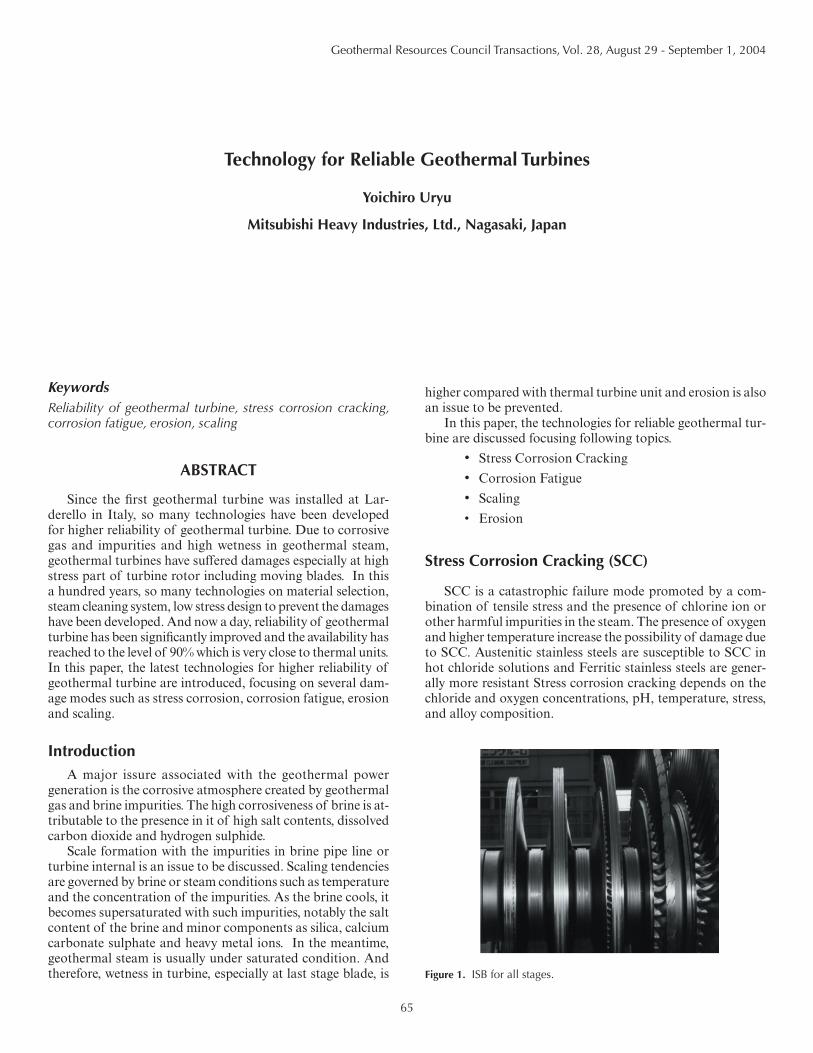
Figure 1. ISB for all stages.

66
Lower stress design is also important factor to prevent SCC. Generally, local peak stress due to centrifugal force should be minimized. For lower stress design, it is important that centrifugal force is decreased and stress concentration is minimized by means of smooth change of section area. Re-sidual stresses from cold working and welding can generate SCC and heat affected zone due to welding or heavy grinding ,where the microstructure was changed and usually the hard-ness comes high, is highly susceptible to SCC. And appropriate heat treatment for stress relief or lowering the hardness is also important measure to prevent SCC.
Based on the above discussions, actual measures against SCC are introduced in this section.
Rotor Material
Rotor is the most important part and special attention to be made to prevent SCC .Cr Mo V material is applied to HP rotor in thermal turbine unit. Low alloy steel such as Cr Mo V is not susceptible to SCC, however we have minimized the concentration of Sulfur and Phosphorous to minimize sus-ceptibility to SCC and improve toughness. The material code of low sulfur CrMoV rotor is 10325MGB and this material have been applied to our geothermal turbine as a standard rotor material.
The concentration of Sulfur and Phosphorous is 0.005%(Max.) and 0.015%(Max.) respectively.
For highly corrosive geothermal steam compared with usual geothermal steam, we have developed 12Cr rotor material. This is more expensive but it was verified in the test facility with actual geothermal that susceptibility to SCC was lower and corrosion rate was also lower as shown in Table 1. Our material code of this 12Cr rotor material is 10325GSR and was applied to Hatchobaru geothermal turbine in 2001.
Rotor Stress Design
Stress concentration occurs at the area where section area changes. In view of stress concentration, we need to specially care about the disc root and blade groove.
For disc root, large corner “R(Radius)” and “Taper shape” are applied to minimize stress concentration or SCC.
At the time we developed Integral Shroud Blade, we ap-plied the large blade root and groove design to reduce the static (centrifugal) stress at the blade root and groove.
Figure 2 shows the improvement in centrifugal stress level of large groove compared with conventional groove.
Corrosion FatigueCorrosion fatigue is fracture mode under the condition
that vibration stresses are imposed on a material in a corro-sive environment. Relatively high vibration occurs at moving blades and measures against corrosion fatigue should be considered in design or manufacturing process of moving blades.
Material Selection
The reduction of corrosion fatigue strength due to corro-siveness must be taken into consideration in the selection of blade materials for a geothermal turbine. Corrosion fatigue tests at several geothermal fields were conducted to deter-mine the reduction of fatigue strength due to corrosiveness of geothermal steam. The reduction should be reflected in the design.
17-4 PH (17Cr-4Nickel Precipitation Hardening stainless steel) has been adopted for the first stage moving blade, which is in the most corrosive zone close to saturated line and is susceptible to scale deposits, although 12 % Cr stainless steel is usually used for the blades. The 17-4 PH steel has higher corrosion fatigue strength than 12% Cr stainless steel as shown in Figure3.
For more corrosive geothermal steam than usual, Titanium alloy (Ti-6Al-4V) is applied for higher reliability in terms of corrosion fatigue as well as SCC.
Figure 3 shows corrosion fatigue strength comparison for three kind of materials.
Table 1. Comparison of Rotor Material.
*Corrosion rates are relative values, and the data is based on the actual geothermal steam circumstance.
Figure 2. Comparison of blade groove.
Uryu

67
Integral Shroud Blade (ISB)
ISB was developed for the following purposes.
- Lower vibration stress (Stronger against corrosion fa-tigue)
- No scale deposit around tenon or shroud band hole (Stronger against SCC at tenon or shroud hole)
- Low centrifugal stress at blade root or groove (Stron-ger against SCC and Corrosion fatigue at the root or groove)
- Higher efficiency
In ISB construction, adjacent blades come into contact with each other at the shrouds due to a twist-back movement generated by the centrifugal force on the blades during op-eration, as illustrated in Figure 5. The mechanical damping induced by this physical contact reduces the vibration stress
to less than 20 % of conventional grouped blades (Figure 6). At the rated rotor speed, all blades are connected together at the integrated shrouds to form an infinity blade group. This design reduces the number of vibration mode which require the tuning of blade frequencies in order to avoid the resonance. And therefore, reliability of the blade has improved because of easier frequency tuning.
With ISB construction, design loading of the blade, defined as maximum steam flow rate per unit annulus area (pounds/ft2/hr), is also increased by 1.5 times relative to the conventional grouped blade, which makes great contribution to higher ca-pacity and reliability.
ErosionSteam condition at turbine inlet is almost saturated and
wetness in turbine, especially at last stage blade, is higher than thermal turbine case.
So, measures against erosion at last stage blade leading edge should be applied.
Following measures were developed and have been ap-plied to our geothermal turbines. And the effectiveness of following measures have been verified in long period of actual operation.
- Drain catcher at outer ring of diaphragm for removing drain from blade path
Figure 3. Comparison of each blade material.
Figure 4. Integral Shroud Blade (ISB).
Figure 5. Shroud contact during operation.
Figure 6. Comparison of vibratory stress.
Uryu

68
- Drain groove dug at concave surface of last stage stationary blade for removing drain from blade path
- Hollow nozzle at last stage for removing drain from blade path
- Stellite strip on the leading edge of last stage blade to protect blade material from erosion
- Ample axial space between stationary blade and moving blade to decrease drain energy that cause erosion
Drain Catcher
The drain catchers provided at each stage are significantly important devices to avoid drain erosion and to decrease moisture loss. Water droplet is collected by the drain catcher. In this regard, the space between stages and the shape of the drain catcher, which affects the efficiency of drain catching, has been determined through an analysis of water droplet behavior in model testing. Drain erosion of the long blade is prevented by further decreasing the wetness in the steam flowing into the moving blade by grooves dug on the concave surface of the last stationary blade. Figure 7 shows the typical drain catcher.
Hollow Nozzle
The drain on the stationary blade is evacuated through the slit on the stationary blade surface and the drain hole on the inside of the blade profile (Figure 8). A hollow nozzle is
more effective at removing the moisture, thereby protecting the rotating blade from erosion, than the typical groove on the concave surface of the stationary blade. For example, the Darajat project turbine utilize hollow nozzles at last two stages (both L-0 and L-1 stage), considering the high moisture content due to high main steam pressure and low exhaust pressure.
ScalingIn this section, scaling at first stage nozzle in turbine is
discussed while there is other harmful scaling in re-injection pipe line. If scale deposit at first stage nozzle, then flow area of first stage nozzle reduces and main steam flow rate decreases in case main steam pressure is maintained. In this case, gen-erator output decreases. This is a problem caused by the scale deposited at first stage nozzle. In the meantime, if heavy scale deposit at first stage nozzle and at the axial space between moving blade and the nozzle, it is possible that heavy rubbing occur and rotor is over-heated by heavy rubbing. In case rotor is over-heated, then microstructure of rotor material is changed to martensite and SCC may occur at the over heated area. This is another problem.
In any case, heavy scaling at the first stage nozzle should be prevented in actual operation in view of economical and safe operation.
Scaling condition can be monitored by the following pa-rameter.
Blocking ratio(BR) = (Pressure after governing valve)/(main steam flow rate)
It is necessary to record BR0 that should be taken at the time no scaling deposit just after overhaul. Then BR should be taken continuously and periodically and compared with BR0 . If much increment in BR was found, some measures
should be taken to prevent above problems.
Water Cooled Nozzle
Water cooled nozzles were adopted for the first stage in Sumikawa geothermal power plant in Japan. All nozzles are provided with holes in profile for clean and cool water to pass through to reduce nozzle metal temperature and thereby prevent re-evaporation and concentration of drain fluid, which causes scaling on first stage nozzle.
First overhaul inspection after almost 1year operation show that scale deposited on the
first-stage nozzles was minimal, indicating that the water cooled nozzles were effective. It was concluded that cooling water effectively decreased nozzle metal temperature and prevented re-evaporation of drain.
Figure 7. Typical drain catcher.
Figure 8. Hollow nozzle.
Figure 9. Water Cooled Nozzle.
Uryu

69
Small amount of scale was collected and analyzed, and the chemical composition are listed in Table 2.
Water Washing
Water cooled nozzle is designed for no scale deposition and Water Washing is designed to wash or remove the deposited scale.
Small amount of water is injected to main steam before main stop valve and this water is extracted from the outlet of hotwell pump. The injected water dissolves and removes scale deposited on the first stage nozzles. Chemical analysis of the scale in Yamagawa geothermal power plant in Japan is shown in Table 3. The ratio of water soluble scale components
Table 2. Chemical analysis of scale (Sumikaa Geothermal Power Plant).
Table 3. Chemical analysis of scale (Yamagawa).
such as Na and Cℓ was relatively high, so water washing was considered effective. Water washing was carried out for 2 years after the initial commercial operation. If the injected water flow rate is too high, there is a possibility of erosion, so water at 1~2 wt% of main steam flow was injected. As a result, the nozzle blocking ratio decreased as shown in Figure 11, and water washing was effective to remove scales.
Reference
S. Saito, T. Suzuki, J. Ishiguro and T. Suzuki, 1998, “Development of Large Capacity Single-Cylinder Geothermal Turbine.” GRC Trans-actions, Vol.22.
Y. Nakagawa and S. Saito, “Geothermal Power Plants in Japan Adopting Recent Technologies.” World Geothermal Congress 2000.
Figure 10. System diagram of turbine water washing.
Figure 11. Effect of turbine water washing.
Uryu

70