notes on some simple strain gauge networks commonly...
TRANSCRIPT

C.P. No. 415 (20,554)
A.R.C. TechnIcal Report A.R.C. Technical Report
MINISTRY OF SUPPLY
AERONAUTICAL RESEARCH COUNCIL
CURRENT PAPERS
Notes on some Simple Strain Gauge Networks commonly used with
Wind Tunnel Balances
1. R. Anderson
LONDON. HER MAJESTY’S STATIONERY OFFICE
1959
PRICE 2s. 6d. NET


C.P. No. 415
U.D.C. No. 533.6.071.3 : [email protected]
Teohn~oal Note No. Aearo 2581
@z-t, 1958
ROYAL AIRCRAFT ESTABLISHMENT
N'Yl!ESONSOMESIMPIESTRAINGAUGENETWORKS CXMIONLY USED WlTH WIND TUNNEL BALAh'CFS
J. R. Anderson
Vheatstone bridge networks of four ancl of eight resistance strain gauges are considered from the point of view of the errors which may arise fromthe assumption of a linear relation between applied strain and brdge output. The effects d mismatch of initial resistance an3 gauge factor are also examined.

LIST OF CONTENTS &g
1 IiWRODUCTION 3
2 BMIC ASSUMPTIONS ANDD'KF'INITIONS 3
3 ANALYSIS OF THE i3jIfdB.E 2DUR GAUc;E BRIDGE 4
4 BRIDQS OFEIGB!C STRAIN GAUGES 7
4.1 Series arrangement lk.2 Parallel arrangement ii
5 THE EFFECT OF UNMA!l!CHED GAUGFi FACTORS IO
6 NON-CANCELu1TION OF .WjW@ERING STRAINS DUE TO UIWATCBED GAUGE FACTORS II
~STRATIONS - Figs.i-3
LIST OF ILLUSTRATIONS
Fo-gauge Wheatstone bridge
Eqht-gauge bridge (Series arrangement)
Eight-gauge briiige (Parallel arrangement)
Fp&.
1
2
3
-2-

1 INlPCJJJCTION
The object of this short Technical Note is to collect together and record a few simple results obtained from the analysis of sac Wheatstone bridge networks of resistance strain gauges in ccmmon use. The main emphasis is placed on the magnitude cf errors which mey arise from the assumption that the bridge output is linear with applied strain. The effects of mismatch in resistance and gauge factor between the strain gauges foxming a bridge are also examined.
2 BASIC ASSXJlPl!IONS AND DFECNITIONS
The strain gauge networks considered are of Wheatstone bridge type, although it is inmaterial if all the srms are active or not. Supply voltage and out-of-balance indicator are assumed to have no electrlcal interaction with the state of resistive unbalance result- from strains applied to the strain gauges, and the networks are considered purely resistive. This ensbles the voltage unbalance due to strain to be taken as linear with the applied voltage, and tc be obtained by the simple consideration of changes in resistance of the gauge elements.
The resistance parameters of interest are defined as,follcws.
R is the naninsl, unstrained resistance of the strain gauge
61 is the initial fractional deviation frcm naminal of strain gauge 1~0.1, so that its total unstrained resistance is R(l + 6,).
Al is the fractional reslstsnce change of strain gauge No.i due to mechanical or electricsl strain
so that
R1 = R(1+6,)(l+A,)
R2 = R(l +fj2)(1+A2), etc. (1)
We have further to define a gauge factor, k, (assumed negative) such that the change in resistance due to mechanical strain is equal to k times the change in strazn, or
A1 = k, e,
A2 = k2 e2 , etc., (2)
where e ,, e2, etc. are the zrechanical strains applied to strain gauges
Nos.l,Z, etc.
In normal practice, 6 will be limited to about ZO.005 ohms per ohm, i.e. about $ per cent, by considerations cf linearity in the indxating equiped, which will not be examined here. The value of the mechanical strain, e, u&ng steel balances, is normally limited to about +O.OOl inches per inch, so that A will not exceed about +O.C02 oinns per ohm, assuming k to have a ncxninsl value of 2, which is Fughly appropriate to the strain gauges most comnonly uscd. In later sections, the consideration of possible errors will be restricted to these maxdxn variations in the main parameters.
-3-

3 ANALYSIS OF THE SIMPLE FOUR GAUGE BRIDGE
The network considered is depicted in Flg.1 and consists of four resistances arranged ii-~ a conventional Wheatstone bridge: any or all of the resistances may represent strain gauges, although we shall assume here that all do, the most general ease. The results for particular cases can be obtained by the simple expedient of equating to aero in the general result the A's corresponding to fixed resistances.
A voltage, V, is applied across the corners AC, causing in general a small voltage, dV, to appear across the corners ED, as shown. The solution to the problem is taken to be the variation in the ratlo dV/v corresponding to the elmtricsl strains imposed on the strain gauges.
Now clearly, inmiting down the equations, we need consider initially only one pair of adjacent arms, such as R R
1 2' since those for the other
Pair, R3 S, , will follow by changing the subscrjptsappropriately. Such
pairs of gauges connected across the voltage supply are colloquially referred to as 'hdf-bridges'.
Assuming, then, that each resistance represents au active strain gauge, the value of the voltage at point B, say, referred to the point C is given by
Vat/v = R2/(R,+R2)
= R(~+S~)(I+A~)/~R(I+~,)(I+A,)+R(I +62)(~+~2)j
= ~~+~2)~~+~2)/~(1+~,)(1+A,)+(1+62)(1+A2)]
in the strained condition of the gauges. The value in the initial, unstrained condition is obtained by putting A, = A2 = 0. Thus the change
inV BC/V due to strain in the half-bridge is
dV& = (I+ S,)(l +A,)/I(l + 6,)(1 +A,) + (1 +S2)(1 +A,)]
- (i+62)/I(l+6,)+(l+62)j (3)
= $ .(A2-A,)(l+6,+62+6162)Ii+~ l (6,+62)j-iii+&. (6,+62)+~..,(1+6,)+~.4(~+62~-1. _
Use of the bincmi al theorem enables this expression to be expanded, snd simplified tn sufficiently high orders of 6 and A as
“.&.p = &. (A2-Al)[l~.(A,+Ad+~.(A,+A2)2-~.(6,-6~)2+$.(~2-~,)(6,-62)~
(4)
-4-
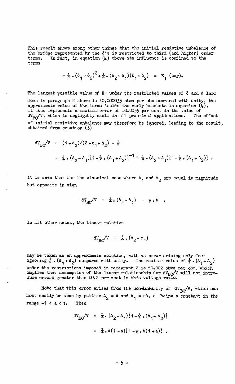
This result shows mong other the bridge represented by the terms. In fact, in equation terms
things that the initial resistive unbalance of 6's is restricted to third (and higher) order (4) above its influence is confined to the
- $.(S, -q2+s. (A2-A,)(6, -b2) = E, (say).
The largest possible value of E, under ths restricted values of 6 and A led
down in paragraph 2 above is +0.000035 ohms per ohm compared with unity approximate value of the terms inside the curly brackets in equation (4j.
the
It thus represents a maximum error of +O.c035 pzr cent in the value of
%d V, which is negligibly small in ell practical applications. The effect of mitisl resistive unbalance msy therefore be ignored, leading to the result, obtained from equatxon (3)
dVBc/V = (l+A2)/(2+A,+ A2) - ;
= -;. (A,-A,)ll+&.(A,+A,)]-'* $.(A~-A,)~I-+.(A,+AJ] .
It is seen that for the classical case where A, an? A2 are equal in magnitude
but opposite in sign
av,$ = $.(A2-A,) = &.A .
In all other oases, the linear relation
my be taken as an approximate solution, lgncring $.(A,+A2) campared with unity.
with en error arising only from The sxzdmum value of %.(A,+A,)
under the restrictions imposed in paragraph 2 is +0.002 ohms per ohm, which implies that assumption of the lmear relationship for dV ,$J will not intro- duce errors greater than 20.2 per cent in this voltege t ra 10.
Note that this error arises from the non-knearity of dV&, which can
most easily be seen by putting A2 = A and A, = eA, a being a constant in the rage -I< acl. Then
avBp = $. (A,-+I-$ .@,+A,)]
= &.A(1 -a)[l-&.A(l+a)] .
-5-

The error in the voltage ratio incurred by assuming the linear relation is greatest as a-+1 (end the voltage ratio-o), but ths error expressed as a percentage of total output is always less than 0.2 per cent for a finite output, and can be seen to be actuslly 1/1O.(1 +a) per cent.
The solution for the oxnplete bridge may be written down as
= $*(A,-A,)[l+&. (A,+A~)]-'-$.(A~-A~)[I+~.(A~+A~)]-~
+.(A,-A,-Aj+Ak)
where use of the linear approximation incurs errors of not more than about 20.2 per cent in.dV/V, provided the outputs of the individual half-bridges sre of opposite sign, so that their difference is greater than either. Such an arrangement is sanetimes called an 'additive' bridge. In the case of an additive bridge with each arm sustaining strains of the same Magi- tude, note that zero error is incurred.
The alternative arrangement, where the output of the bridge as a whole 1s less than one or other of its component half-bridges is sometimes called a 'difference' bridge, ad appreciable prcentage errors may be incurred by the assumption of linesrlty of outpd, having regard to the decreased output itself.
These errors arise under conditions where the separate outputs from the half-bridges tend to balance out, whereas the errors involved in the llnesr assumption tend to accumulate. This can be demonstrated easxly to be the case where two strain gauges in opposite alms of the bridge undergo strains which are smsll and cwrable in vtude, whereas the remaining two gauges suffer large strains, comparable in magnitude but opposite in sign. Such a case is represented by
Al = A
A2 = -sA
A3 = -bA
AL = -(i tc)A
where a, b and c represent small quantities compared with unity.
The linear output dV/v = -$ (A,-A2-Oj+$+)
= -$.A(a+b+c)
in the present case, and is small compared with -& .A.
-6-

The error in the linear assumption can easily be shown to be
- $(A,2-A22-Aj2+Aq2) ,
In GUI- special case this reduces to -2. A2(2 +2c-a2-b2+c2), which may be approximated as -$. A2.
It is now obvious that when (a+b +z) is comparable in magnitude with A, the error is of the same order as the output, and that if (a+b +o) further approaches zero, the linear output will correspondingly deorease further, whereas the error will remain virtuslly constant. The maximum value of this error is about -1 x 10⁻⁶ in our range ~8 interest, ati it follows therefore that the standard of ZO.2 per cent error which applies to more. usual strain gauge arrangements can be sssumd only when the output of this special type of difference bridge is 2500 x 104 or greater, i.e. a+b+cls of orderplus or minus uruty. Fortunately, in practice the arrangement likely to give the largest errors is seldom encountered, since the gauges of any half-bridge are normally strand more or less equally positive and negative.
In conclusion, then, the additive bridge may be used with confidence that the linear approxtition will not introduce errors a? more than about 20.2 per cent in bridge output, whereas the difference bridge must be placed in a different category, and some care exercised in assuming the validity of the linear relation.
4 BRIDGFS OF EIGHT STFAIN GAUQXS
These Wheatstone bridge arrangements are similar tothosefor four gauges, but e loy the strain gauges conneded either in series (Pig.2) or in parallel (Fig.3 in each of the four arms instead of a smgle gauge. "p The analysis Trcceeds in both cases in a similar manner to that employed in the preceding paragraph, namely by expansion of the relation for voltage ratio to sufficiently high orders of 6 and A, using the binamial theorem. The manipulation of terms, however, is considerably more tedious.
4.1 Series arrangement (Fig.2)
The result for the left-hand half-bridge is
av&v = -$.(A,-A~+A~ -A6)[l-$.(A,+A2+A5+A6)]
- 1/6. (A,- A5)(“,- S5) +%6(A,- A6)(S2- S6).
The higher order telms in this equation may be considered in two parts. Firstly, the last two terms
- &4,- A5)(“, - h5) +I’& .(A,- A& - 66)
(5)
(6)
which are the only ones involv' T
initisl resistance mismatching, may amount in magnitude to as muoh as 25 x IO- under oonditlans where the output would. be expected to be zero, nanely, when A,+A 5 =O =A2+A6. This figure is derived'
-7-

within the limitations on 6 ad A of paragraph 2 above, and cmpares vrith a maximum output from the half-bridge of +lC00 x 10e6. The error incurred by igncring these terms is thus signrficant, and may became very large in scme applications. The significance of the terms may be severely reduced, however, by matching the initial resistsnoes of the strmn gauges, that is, by ain@ (6, - 65) sax-d (s2 -b6) sufficiently near zero.
An alternative approach suggests itself, in that the last two terms of equation (5) maybe made very mall by mslcing Al-A5 :: 0 $ A2-A6
This tinplies that the pairs of strain gauges in the same arms of the bridge should tiergo almost equal electrical strain. This is a little difficult to arrange in practice due to variations between ths gauge factors of the individual gauges, and is impossible where the main use of the eight gauge network arises from the desire to eliminate interacting strains, whmh effectively ensure that this condition cannot be satisfied. (It should also be noted that in situaticns where the condrrtion csn be satisfied for all four arms of the brdge, there would appear to be advantages certainly no disadvantages, in using a simple four gauge network I
and . This
latter approach would appear, therefore, to have little practical appli- catlon, and the last two terms in equation (5) may be ignored only if attenticn is paid to matching the initial resistances of the strain gauges in the same arms of the bridge.
In the second place, the inherent non-linearity of the network with strain is contained in the factor
[I -4. (A, +A2 +A5 +A6)j .
I
Under the restrictions on A which we have assumed., this factor departs fran the value unity by up to 20.002. Thus errors of up to +0.2 per cent in N&V may be incurred frmthis quarter in assummg the linear relation
dvBc/v = -+,.(A,-A2+A5-A6).
We msy now write down the approxmate solutxon to the complete network as
= -&.(A,-A2+A5-A6-A3+A,+-A,+A&
to an accuracy of about 20.2 per cent in N/V, provided the strain gauge resistances in each arm are matched, i.e. 6 ,-65' 62-6 ) 6 -6 6 3 7' 6&3 am all approximately zero, (note that this is 8n extra restriction on initial resistive balance compared with the simple arrangermmt of four gauges), ard provided the half-bridges are connected as sn additive bridge, i.e. the bridge is arranged such that the total output is greater than either of the ind~vidud half-bridges. If this latter conditxon is not satisfied and a difference brdge arrangement IS used., the errors arising frm the assumpticn of linearity may be found to be greater than 20.2 per cent in output, the general arguement following the lines of that detailed for the fcur gauge bridge (Section 3).
4.2 Parallel arrsn~ment (Fig.3)
Once more, the result for the left-hand half-bridge is
-8-
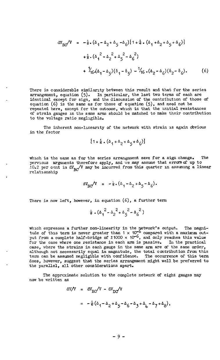
dVbG/v = -$;.(A,-A2+A5-A6)!1+&.(A,+A2+A5+A6)j
+&. (A,' -A22+A52-A62)
+ 164 y A,-A5)(6,-+ - ‘46 &2-“6)(62- h6). (6)
There is considerable similarity between this result and that for the series arrangement, equation (5). In particular, the last two terms of each are identical except for sign, end the discussion of the contribution of those of equation (6) is the same as for those of equation (5), and need not be repeated here, except for the outcome, which is that the initial resistances of strain gauges m the same - should be matched to make their contribution to the voltage ratio negligible.
The inherent non-lmeanty of the network with strain is again obvious in the factor
which is the saze as for the series arrangement save for a sigs change. The pervious arguments therefore apply, and Ire msy assume that errcaBaf up to LO.2 per cent in dV BP maybe incurred fromthis quarter in assuming a linear relationship
NBC/” = -$.(A,-A2+A5-A6).
There is now left, however, in equation (6), a further term
which expresses a further non-linearity in the etwork's output. The magni- tude of this term is never greater than 1 x l(r 2 put from a complete half-bridge of +I000 x 1~6,
compared with a maximum out- and only reachesthisvslue
for the case where one resistance in each arm is passive. In the practical case, where the strains in each gauge in the same arm are cf the seme order, although not necessarily equal in magnitude, the total contribution from this term can be assumed negligible with confidence. The occurrence of this term does, however, suggest that the series arrangement might well be preferred to the parallel, all other considerations apart.
The approximate solution to the complete network of eight gauges may now be written as
dV/v = dVBC/V - dVDch'
= -&(A,-A,+A -A -A +A -A +A), 563478
-9-
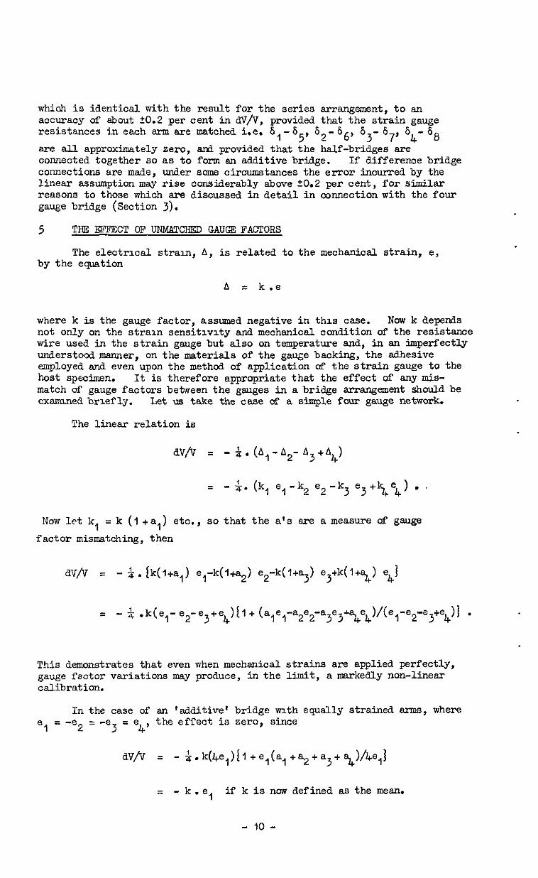
which is identical with the result for the series arrangement, to an accuracy of about to.2 per cent in N/V, provided that the strain gauge resistances in each arm are matched i.e. 6 ,-by h2- 66' 63- 67' s4- 68 are all approximately zero, a& provided that the half-bridges are connected together so as to form an additive bridge. If differenoe bridge connections are made, under some oiroumstanoes the error incurred by the linear assumption may rise considerably above 20.2 per cent, for similar reasons to those which are discussed in detail in connection with the four gauge bridge (Section 3).
5 THE KPFECT OF UNMATCHED GAUGE FACTORS
The eleotrloal stram, A, is related to the mechanical strain, e, by the equation
A = k.e
where k is the gauge factor, assumed negative in this case. Now k depends not only on the strain sensitlvlty and mechanical condition of the resistance wire used in the strain gauge but also on temperature and, in an imperfectly understood msnner, on the materials of the gauge backing, the adhesive employed and even upon the method of application of the strain gauge to the host spe4men. It is therefore appropriate that the effect of any mis- match of gauge factors between the gauges in a bridge arrangement should be ex-ed briefly. Let us take the csze of a simple four gauge network.
The linear relation is
dV/v = - $.(A,-A2-A3+A4)
= -Q$. * (k, e,-k2 e2-k3 s3+teq) l
Now let k, = k (l+a,) etc., so that the a's are a measure a? gauge
factor mismatching, then
dV/V = - i.lk(l+a,) e,-k(l+a2) e2-k(1+a3) e3+k(l+y) elt]
= - $.k e,-e2- 3 4 ( e +e )I1 + (ale,-a2e2-a3e3yb)/(e,-e2-e3+aq 11 -
This demonstrates that even when mechanical strains ars applied perfectly, gauge feotor variations may produce, in the limit, a markedly non-linear calibration.
In the case of an 'additive' bridge wrth equally strained srms, where
el = -e
2 = -e3 = e4' the effect is zero, since
&V/v = - $.k(4e,)Ll+e,(a,+a2*a3+a4)/4e,j
= -k.e, if k is now defined as the mean.
- 10 -

Non-lxxear effects may obviously be minmised by the approximate matching of gauge factors. This, however, is a process which would appear to have little practlcsl possibility. It 1s evident, then, that m designing a stram gauge balance, It is useless to aim for perfomance or mteractlcns of better than about +I per cent, which m the, tolerance on gauge factor usually quoted by the manufacturer of the resistance stram gauges.
6 NON-CANCELLATION OF INTERFERING STRAINS DUE TO UN%KTCHEE GAUX FACTORS
It is frequently found in the deszgn of strain gauge balances that strains due to the designed structural load. occur only in the presence of strains arismg frcm other loads which are not required to contribute to the output of the bridge. It is convenient to arrange the strain gauges on the balance structure and in the Wheatstcnc brdge in such a manner that the interfering strains are effectively cancelled, ad the required atrains effectively sumed, 50 far as the bridge output is concerned. Takmg the simple four gauge brdge as an example,
m/v = -+.(A,-A,-a3+aq)
= - $.(k, e,-k2 e2-k3 ej+kq e4)
where the symbols are as defined in paragraph 5.
Now suppose that the strams e,, etc., are compounded of a strain em
required to contrxbute to the measurement and an interfering stram ec reqUred to be cancelled. Then if
el = P, em+q, ec
e2 = P2 em+q2 ec
e3 = p3 emfq3 ec
"4 = p,em+q+eo
where the p's snd q's m-e constants which may have any values within the range +I , we have
m/v = - 4. Iem&, p,-k2P2-k3 P3+\ $1
+ ec(k, 9, - k2 %- k3 q3 +$ ‘++)I *
Puttug as before k, = k(l+a,) etc., where k is the mean gauge factor
( I.e. a,+a2+a3+aq = 0).
av/v = - ;'4 kje,(p, -~2- P3+Pq)+em(P, y-P2 a2-p3 a3+Pq y+)
+eo(9,-~-q3+qt)+ec(9, a,-$? a2-q3 a3+y+ "4 11
- 11 -

The condition that the interfering strains should cancel to the first order, is now seen to be
and the interaction then remaining csnbe expressed as a pzmentage of bridge output,
+ (P, a,- p2 a2 -p3 a3+p4 %)I.
ldaximm signal (U/V) and minimum interaction are obtained frcmnthe network if p, = -p2 : -p3 = p,+ = 1, thus definmg an 'adifitive' bridge with squally strained arms. The interaction my then be written
1% = 100 x (ec/em).$.(q, a,-% a2-qj s3+\ 84).
In the worst case, where gauge factors may differ by +I per cent, the interaction becomes
The factors q are required to satisfy two conditions; that shown above for first order cancellation of interference, and the restriction M value to ?I. In the majority of practical cases, these conditions ars satisfied by
9 = %= qJ = q&=1,
and then the interference may be expressed as
Good &ram gauge bslance designs aim at keeping the ratio efi, to a
max%mm of unity, but cases do arise in practice where this 1s difficult, snd the value may be as high as IO or 15. It must be borne in mind, then, that unfavourable cddnations of gauge factor variations may penalise the balance design with interactions of equivalent percentage.
- 12 -
.U.2078.C.P.Yl5.K3 - Prmteci cn Great Britarn

FIGI. FOUR-GAUGE WHEATSTONE BRIDGE.
A
6 V 0
FlG.2. EIGHT-GAUGE BRIDGE (SERIES ARRANGEMENT)

6 6
c c
FIG. 3. EIGHT - GAUGE BRIDGE (PARALLEL ARRANGEMENT)

C.P.N;;, 4 I5
A.R.C. Tech&al Report
0 Crown Copyright 1959
PublIshed by HER MAJESTY’S STATIONERY OFFICE
To be p&hued from York House, Kmgsway, London w.c 2
423 Oxford Street, London w I 13~ Castle Street, Edinburgh 2
109 St. Mary Street, CardlIT 39 Kmg Street, Manchester 2
Tower Lane, Bristol 1 2 Edmund Street, Bwmingham 3
80 ChIchester Street, Belfast or through any bookseller
S.O. Code No. 23-901 I-IS
C.P. No. 415