notes on micro controller and digital signal processing
TRANSCRIPT

8/6/2019 Notes on Micro Controller and Digital Signal Processing
http://slidepdf.com/reader/full/notes-on-micro-controller-and-digital-signal-processing 1/70
Introduction to the Fourier Transform
Virtually everything in the world can be described via a waveform - a function of time, space or some other variable. For instance, sound waves, electromagneticfields, the elevation of a hill versus location, the price of your favorite stock versus
time, etc. The Fourier Transform gives us a unique and powerful way of viewingthese waveforms.
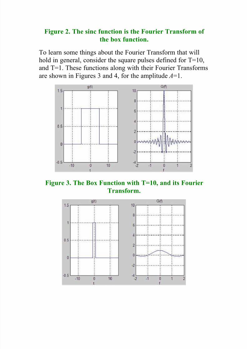
The Fourier Transform of the Box Function
Continuing the study of the Fourier Transform, we'll look atthe box function (also called a square pulse or square wave):
Figure 1. The box function.
In Figure 1, the function g(t) has amplitude of A, and extendsfrom t=-T/2 to t=T/2. For |t|>T/2, g(t)=0.
Using the definition of the Fourier Transform (Equation [1]above), the integral is evaluated:

8/6/2019 Notes on Micro Controller and Digital Signal Processing
http://slidepdf.com/reader/full/notes-on-micro-controller-and-digital-signal-processing 2/70
[Equatio
The solution, G(f), is often written as the sinc function, whichis defined as:
[Equatio
[While sinc(0) isn't immediately apparent, using L'Hopitals
rule or whatever special powers you have, you can show thatsinc(0) = 1]
The Fourier Transform of g(t) is G(f),and is plotted in Figure2 using the result of equation [2].
8/6/2019 Notes on Micro Controller and Digital Signal Processing
http://slidepdf.com/reader/full/notes-on-micro-controller-and-digital-signal-processing 3/70
8/6/2019 Notes on Micro Controller and Digital Signal Processing
http://slidepdf.com/reader/full/notes-on-micro-controller-and-digital-signal-processing 4/70
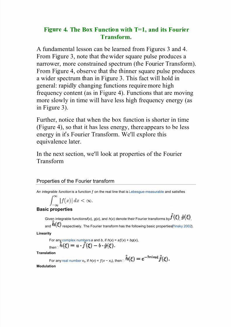
Fi 4 T B Functi n with T and its Fouri r
Transform.
A fundamental lesson can be learned from Fi ures 3 and 4.
From Fi ure 3, note t at t e wider square pulse produces anarrower, more constrained spectrum (t e Four ier Transform).
From Fi ure 4, observe t at t e t inner square pulse producesa wider spectrum t an in Fi ure 3. This fact will hold ingeneral: rapidl changing functions require more high
frequency content (as in Figure 4). Functions that are moving
more slowly in time will have less high frequency energy (as
in Figure 3).
Fur ther, notice that when the box function is shor ter in time
(Figure 4), so that it has less energy, there appears to be less
energy in it s Four ier Transform. We'll explore thisequivalence later.
In the next section, we'll look at proper ties of the Four ier
Transform
Properties of the Fourier transform
An integrable function is a function on the real line that is Lebesgue-measurable and satisfies
Basic properties
Given integrable functions f ( x ), g ( x ), and h( x ) denote their Fourier transforms by , ,
and respectively. The Fourier transform has the following basic properties (Pinsky 2002).
Linearity
For any complex numbers a and b, if h( x ) = a( x ) + bg ( x ),
then
Translation
For any real number x 0, if h( x ) = ( x í x 0), then
Modulation

8/6/2019 Notes on Micro Controller and Digital Signal Processing
http://slidepdf.com/reader/full/notes-on-micro-controller-and-digital-signal-processing 5/70
For any real number 0, if h( x ) = e2ix
0( x ), then .
Scaling
For a non-zero real number a, if h( x ) = (ax ), then . The
case a = í1 leads to the time-reversal property, which states: if h( x ) = (í x ),
then .
Conjugation
If , then
In particular , if is real, then one has the reality condition
And if is purely imaginary, then
Duality
If then
Convolution
If , then
Linear time-invariant system theory, commonly known as LTI system theory, comes from applied
mathematics and has direct applications inNMR spectroscopy, seismology, circuits, signal
processing, control theory, and other technical areas. It investigates the response of alinear and time-
invariant system to an arbitrary input signal. Trajectories of these systems are commonly measured
and tracked as they move through time (e.g., an acoustic waveform), but in applications likeimage
processing and field theory, the LTI systems also have trajectories in spatial dimensions. Thus these
systems are also called linear translation-invariant to give the theory the most general reach. In the
case of genericdiscrete-time (i.e., sampled) systems, linear shift-invariant is the corresponding term. A
good example of LTI system is electrical circuit that can be made up of resistors,capacitors andinductors.,
[1]
The defining properties of any LTI system are linearity and time invariance.
Linearity means that the relationship between the input and the outputof the system is a linear
map: If input produces response and input produces response
then the scaled and summed input produces the scaled and summed
response where a1 and a2 are real scalars. It follows that this can be
extended to an arbitrary number of terms, and so for real numbers ,
Input produces output
In particular ,
Input
produces out put
(E
q.
1)

8/6/2019 Notes on Micro Controller and Digital Signal Processing
http://slidepdf.com/reader/full/notes-on-micro-controller-and-digital-signal-processing 6/70
where c ¡
¢
x £
re ¤
¥ £
l£
rs £ ¦ §
i¦
̈ ©
ts that
ary
er a ¥ ¦
ti¦
© ©
i¦ §
exed
y .
hus if an
input f uncti n can
e represented
y a continuum of input f unctions, combined "linear ly", as
shown, then the corresponding output f unction can be represented by the corresponding continuum of output f unctions, scal
and summed in the same way.
T i me i
ar i ance means that whether we apply an input to the system now
or T seconds f rom now, the output will be identical except f or a time delay of
the T seconds.
hat is, if the output due to input x(t ) is y(t ), then the output
due to input x(t í T ) is y(t í T ). Hence, the system is time invar iant
because the output does not depend on the par ticular time the input is
applied.
he f undamental result in
!
I system theory is that any
!
I system can be character i
" ed entirely by a single f unction called the system's impulse response.
he output of the system is simply the convolution of the input to the system
with the system's impulse response. his method of analysis is often called
the ti me domai n point# of # view. he same result is true of discrete-time linear
shift-invar iant systems in which signals are discrete-time samples, and
convolution is defined on sequences.
Basic Definition of the Z-Transform
The z-transform of a sequence is defined as
X ( z)=�n=í�� x[n] zín
(1)
Sometimes this equation is referred to as the bilateral z-transform. At times the z -transform is defined as
X ( z)=�n=0� x[n] zín
(2)
which is known as the unilateral z-transform.
There is a close relationship between the z -transform and theFourier transform
of a discrete time signal,which is defined as
X (ei)=�n=í�� x[n]eí(in)
(3)
Notice that that when the zín is replaced with eí(in) the z-transform reduces to the Fourier Transform. When
the Fourier Transform exists, z=ei , which is to have the magnitude of z equal to unity.

8/6/2019 Notes on Micro Controller and Digital Signal Processing
http://slidepdf.com/reader/full/notes-on-micro-controller-and-digital-signal-processing 7/70
Elliptic filter
An elli$
%
i&
fil%
er (also ' nown as a Cauer fil
%
er , named after Wilhelm Cauer ) is a signal processing
filter with equali( ed r ipple (equir ipple) behavior in both the passband and the stopband.
) he amount
of r ipple in each band is independently ad justable, and no other filter of equal order can have a f aster
transition in gain between the passband and the stopband, f or the given values of r ipple (whether the
r ipple is equali(
ed or not). Alternatively, one may give up the ability to independently ad just the
passband and stopband r ipple, and instead design a filter which is maximally insensitive to
component var iations.
As the r ipple in the stopband approaches (
ero, the filter becomes a type I Chebyshev filter . As the
r ipple in the passband approaches ( ero, the filter becomes a type II Chebyshev filter and finally, as
both r ipple values approach (
ero, the filter becomes a Butterwor th filter .
) he gain of a lowpass elliptic filter as a f unction of angular f requency is given by:
where 0 n is the nth-order elliptic rational f unction (sometimes
1 nown as a Chebyshev rational
f unction) and
0 is the cutoff f requency
is the r ipple f actor
is the selectivity f actor
2 he value of the r ipple f actor specifies the passband r ipple, while the
combination of the r ipple f actor and the selectivity f actor specif y the stopband
r ipple.
Proper ties
In the passband, the elliptic rational f unction var ies between 3
ero and unity.4
he passband of the
gain theref ore will vary between 5
and .
In the stopband, the elliptic rational f unction var ies between infinity and the discr imination f actor Ln which is defined as:
6
he gain of the stopband theref ore will vary between 7
and .
In the limit of the elliptic rational f unction becomes a Chebyshev polynomial,
and theref ore the filter becomes a Chebyshev type I filter , with r ipple f actor

8/6/2019 Notes on Micro Controller and Digital Signal Processing
http://slidepdf.com/reader/full/notes-on-micro-controller-and-digital-signal-processing 8/70
Since the Butterworth filter is a limiting form of the8
hebyshev filter , it follows that in the
limit of , and such that the filter
becomes a Butterworth filter
In the limit of , and such that 9 0 = 1 and@ Ln = , the
filter becomes aA
hebyshev type II filter with gain
Addressing mode
Addressing modes are an aspect of the instruction set architecture in most central processing
unit (CPU) designs. The various addressing modes that are defined in a given instruction set
architecture define how machine languageinstructions in that architecture identify the operand (or
operands) of each instruction. An addressing mode specifies how to calculate the effective memory
address of an operand by using information held inregisters and/or constants contained within a
machine instruction or elsewhere.
In computer programming, addressing modes are primarily of interest tocompiler writers and to those
who write code directly in assembly language
address modes
The basic addressing modes are: register direct, moving date to or from a
specif ic register; register indirect, using a register as a pointer to
memory; program counter-based, using the program counter as a reference point in memory; absolute, in which the memory addressis contained in the instruction;
and immediate, in which the data is contained in the instruction. Some instructions
will have an inherent or implicit address (usually a specif ic register or the
memory contents pointed to by a specif ic register) that is implied by the instruction
without explicit declaration.
One approach to processors places an emphasis on f lexi bility of addressing
modes. Some engineers and programmers believe that the real power of a
processor lies in its addressing modes. Most addressing modes can be created by
combining two or more basic addressing modes, although building the combination
in sof tware will usually take more time than if the combination addressing mode
existed in hardware (although there is a trade-off that slows down all operations toallow for more complexity).
In a purely othogonal instruction set, every addressing mode would be availablefor every instruction. In practice, this isn¶t the case.
8/6/2019 Notes on Micro Controller and Digital Signal Processing
http://slidepdf.com/reader/full/notes-on-micro-controller-and-digital-signal-processing 9/70
Virtual memory, memory pages, and other hardware mapping methods may belayered on top of the addressing modes.
In mathematics, the diB
C
rete FD
ur ier transf D
r m (DFT) is a specific E
ind of discrete transf orm, used
in F our ier analysis. It transf orms one f unction into another , which is called the f requency
domai nrepresentation, or simply the DF T , of the or iginal f unction (which is often a f unction in the time
domain). But the DG H
requires an input f unction that is d i scret e and whose non-zero values have a
limited (fi nit e) duration. Such inputs are often created by sampling a continuous f unction, liI e a
person's voice.P
nliI
e the discrete-time G
our ier transf orm (DH G H
), it only evaluates enough f requency
components to reconstruct the finite segment that was analyzed.P
sing the DG H
implies that the finite
segment that is analyzed is one per iod of an infinitely extended per iodic signal; if this is not actually
true, a window f unction has to be used to reduce the ar tif acts in the spectrum.G or the same reason,
the inverse DG H
cannot reproduce the entire time domain, unless the input happens to be per iodic
(f orever).H heref ore it is often said that the D
G H is a transf orm f or
G our ier analysis of finite-domain
discrete-time f unctions. H he sinusoidal basis f unctions of the decomposition have the same
proper ties.
G ft & dft
H he input to the D
G H is a finite sequence of real or complex numbers (with more abstract
generalizations discussed below), making the DG H
ideal f or processing inf ormation stored
in computers. In par ticular , the DG H
is widely employed insignal processing and related fields to
analyze the f requencies contained in a sampled signal, to solve par tial diff erential equations, and to
per f orm other operations such as convolutions or multiplying large integers. A key enabling f actor f or
these applications is the f act that the DG H
can be computed efficiently in practice using a f astG
our ier transf orm (
G G H ) algor ithm.
G G H algor ithms are so commonly employed to compute D
G H s that the term "
G G H " is often used to
mean "DG H
" in colloquial settings.G ormally, there is a clear distinction: "D
G H " ref ers to a mathematical
transf ormation or f unction, regardless of how it is computed, whereas " G G H " ref ers to a specific f amily
of algor ithms f or computing DG H s.
H he terminology is f ur ther blurred by the (now rare) synonym finite
G our ier transf orm f or the D
G H , which apparently predates the term "f ast
G our ier transf orm" (Cooley et
al., Q
969) but has the same initialism.
Digital filter
In electronics, computer science and mathematics, a diR
ital filter is a system that per f orms
mathematical operations on a sampled, discrete-time signal to reduce or enhance cer tain aspects of
that signal.S
his is in contrast to the other ma jor type of electronic filter , the analog filter , which is
an electronic circuit operating on continuous-time analog signals. An analog signal may be processed
by a digital filter by first being digitized and represented as a sequence of numbers, then manipulated

8/6/2019 Notes on Micro Controller and Digital Signal Processing
http://slidepdf.com/reader/full/notes-on-micro-controller-and-digital-signal-processing 10/70
mathematically, and then reconstructed as a new analog signal (seedigital signal processing). In an
analog filter , the input signal isT
directlyT
manipulated by the circuit.
A digital filter system usually consists of an analog-to-digital converter to sample the input signal,
followed by a microprocessor and some peripheral components such as memory to store data and
filter coefficients etc. Finally a digital-to-analog converter to complete the output stage. Program
Instructions (software) running on the microprocessor implement the digital filter by performing the
necessary mathematical operations on the numbers received from the AU
C. In some high
performance applications, an FPG A or ASIC is used instead of a general purpose microprocessor , or
a specializedU
SP with specific paralleled architecture for expediting operations such as filtering.
U
igital filters may be more expensive than an equivalent analog filter due to their increased
complexity, but they make practical many designs that are impractical or impossible as analog filters.
Since digital filters use a sampling process and discrete-time processing, they experience latency (the
difference in time between the input and the response), which is almost irrelevant in analog filters.
U
igital filters are commonplace and an essential element of everyday electronics such
as radios, cellphones, and stereo receivers.
Finite impulse response FIR filter
A f inite impulse response (V
IR) filter is a type of a signal processingfilter whose impulse
response (or response to any finite length input) is of finite duration, because it settles to zero in finite
time. This is in contrast to infinite impulse response (IIR) filters, which have internal feedback and may
continue to respond indefinitely (usually decaying). Theimpulse response of an Nth-order discrete-
time FIR filter (i.e. with a Kronecker delta impulse input) lasts for N+1 samples, and then dies to zero.
FIR filters can be discrete-time or continuous-time, and digital or analog.
efinition
A discrete-time FIR filter of order N . The top part is an N -stage delay line with N +1 taps. Each unit delay is az -1
operator
in Z-transform notation.
The output y of a linear time invariant system is determined byconvolving its input signal x with
its impulse response b.

8/6/2019 Notes on Micro Controller and Digital Signal Processing
http://slidepdf.com/reader/full/notes-on-micro-controller-and-digital-signal-processing 11/70
For a discrete-time FIR filter , the output is a weighted sum of the current and a finite number of
previous values of the input. The operation is described by the following equation, which defines the
output sequence y[n] in terms of its input sequence x[n] :
where:
x [n] is the input signal,
y [n] is the output signal,
bi are the f ilter coeff icients, also known as tap weights, that make up the impulse
response,
N is the filter order; an Nth-order filter has (N + 1) terms on the right-hand side.
The x [n i ] in these terms are commonly referred to as taps, based on the structure of
a tapped delay line that in many implementations or block diagrams provides the
delayed inputs to the multiplication operations. One may speak of aW
5th order/X
-tap
filter W
, for instance.
[edit]Properties
An FIR filter has a number of useful properties which sometimes make it preferable to
an infinite impulse response (IIR) filter. FIR filters:
Are inherently stable. This is due to the fact that, because there is no feedback, all thepoles are located at the origin and thus are located within the unit circle.
Require no feedback. This means that any rounding errors are not compounded by
summed iterations. The same relative error occurs in each calculation. This also
makes implementation simpler.
They can easily be designed to be linear phase by making the coefficient sequence
symmetric; linear phase, or phase change proportional to frequency, corresponds to
equal delay at all frequencies. This property is sometimes desired for phase-sensitive
applications, for example data communications,crossover filters, and mastering.
The main disadvantage of FIR filters is that considerably more computation power in a
general purpose processor is required compared to an IIR filter with similar sharpness
or selectivity, especially when low frequency (relative to the sample rate) cutoffs are
needed.Y
owever many digital signal processors provide specialized hardware features to
make FIR filters approximately as efficient as IIR for many applications.
Filter design

8/6/2019 Notes on Micro Controller and Digital Signal Processing
http://slidepdf.com/reader/full/notes-on-micro-controller-and-digital-signal-processing 12/70

8/6/2019 Notes on Micro Controller and Digital Signal Processing
http://slidepdf.com/reader/full/notes-on-micro-controller-and-digital-signal-processing 13/70
LTI system theory
Linear time-invariant system theory, commonly known as LTI system theory, comes from applied
mathematics and has direct applications inNMR spectroscopy, seismology, circuits, signal
processing, control theory, and other technical areas. It investigates the response of alinear and time-
invariant system to an arbitrary input signal. Trajectories of these systems are commonly measured
and tracked as they move through time (e.g., an acoustic waveform), but in applications likeimage
processing and field theory, the LTI systems also have trajectories in spatial dimensions. Thus these
systems are also called linear translation-invariant to give the theory the most general reach. In the
case of genericdiscrete-time (i.e., sampled) systems, linear shift-invariant is the corresponding term. A
good example of LTI system is electrical circuit that can be made up of resistors, capacitors and
inductors.,[1]
The defining properties of any LTI system are linearity and time invariance.
Linearity means that the relationship between the input and the output of the system is alinear
map: If input produces response and input produces response
then the scaled and summed input produces the scaled and summed
response where a1 and a2 are real scalars. It follows that this can be
extended to an arbitrary number of terms, and so for real numbers ,
Input produces output
In particular ,
Input
produces out put
(E
q.
1)
where c and x are scalars and inputs that vary over a continuum indexed by . Thus if an
input function can be represented by a continuum of input functions, combined ̀linearly
̀, as
shown, then the corresponding output function can be represented by the corresponding
continuum of output functions, scaled and summed in the same way.
T ime invariance means that whether we apply an input to the system now
or T seconds from now, the output will be identical except for a time delay of
the T seconds. That is, if the output due to input x (t ) is y (t ), then the output
due to input x (t T ) is y (t T ).a
ence, the system is time invariant because
the output does not depend on the particular time the input is applied.

8/6/2019 Notes on Micro Controller and Digital Signal Processing
http://slidepdf.com/reader/full/notes-on-micro-controller-and-digital-signal-processing 14/70
Frequency Transformation
We need to apply a suitable frequency transformation, if we wish to design bandpass, bandstop and high-pass filters, using the low-pass approximating function analysis previously covered. The block diagram, shown in figure 5.25, illustrates the procedure, which produces, from the specification supplied, the required high-pass approximating function.
Microcontroller
A mib rocontroller (sometimes abbreviated µC, uC or MCU) is a small computer on a
single integrated circuit containing a processor core, memory, and
programmable input/output per ipherals. Program memory in the f orm of c
d e
flash or d
f
Pe
d
M is
also often included on chip, as well as a typically small amount of e
AM. Microcontrollers are designed
f or embedded applications, in contrast to the microprocessors used in personal computers or other
general purpose applications.
Microcontrollers are used in automatically controlled products and devices, such as automobile
engine control systems, implantable medical devices, remote controls, office machines, appliances,
power tools, and toys. By reducing the size and cost compared to a design that uses a separate
microprocessor , memory, and input/output devices, microcontrollers make it economical to digitally
control even more devices and processes. Mixed signal microcontrollers are common, integrating
analog components needed to control non-digital electronic systems.
Some microcontrollers may use f our-bit words and operate at clock rate f requencies as low as 4 kHz,
f or low power consumption (milliwatts or microwatts). f hey will generally have the ability to retain
f unctionality while waiting f or an event such as a button press or other interrupt; power consumption
while sleeping (CPg
clock and most per ipherals off ) may be just nanowatts, making many of them
well suited f or long lasting battery applications.d
ther microcontrollers may serve per f ormance-cr itical
roles, where they may need to act more like a digital signal processor (DSP), with higher clock speeds
and power consumption.

8/6/2019 Notes on Micro Controller and Digital Signal Processing
http://slidepdf.com/reader/full/notes-on-micro-controller-and-digital-signal-processing 15/70
difference between data and program memory
Data memory = where you place your variables. You can read and write values.
Program memory = where the application is stored. Some chips allows parts of the
program memory to be modified in blocks (segments), but you can't store variables in
the program memory. It is normally possible to store constants - i.e. initialized variables
that you do not change - in the program memory.
Your PC also has data memory and program memory. But the program memory is verysmall in the PC - it is just for storage of the BIOS - the boot messages you see when the
PC boots, and (often, but not always) the configiguration pages where you define if you
have a floppy installed, if the computer should support a USB keyboard etc.
Watchdog timer
A watchdog timer (or com uter operating proper l (COP) timer) is
a computer hardware or software timer that tr iggers a system reset or other corrective action if the main program, due to some f ault
condition, such as a hang, neglects to regular ly service the watchdog
(wr iting a "service pulse" to it, also ref erred to as "kicking the dog",
³petting the dog´, "f eeding the watchdog"[1]
or "waking the watchdog").
he intention is to br ing the system back f rom the unresponsive state
into normal operation.
Watchdog timers can be more complex, attempting to
save debug inf ormation onto a persistent medium; i.e. inf ormation
usef ul f or debugging the problem that caused the f ault. In this case a second, simpler , watchdog timer ensures that if the first watchdog
timer does not repor t completion of its inf ormation saving task within a
cer tain amount of time, the system will reset with or without the
inf ormation saved. he most common use of watchdog timers is
in embedded systems, where this specialized timer is often a built-in
unit of a microcontroller .
Even more complex watchdog timers may be used to
run untrusted code in a sandbox.[2]
Watchdog timers may also tr igger f ail-saf e control systems to move
into a saf ety state, such as turning off motors, high-voltage electr ical
outputs, and other potentially dangerous subsystems until the f ault is
cleared.
or those embedded systems that can't be constantly watched by a
human, watchdog timers may be the solution. or example, most
8/6/2019 Notes on Micro Controller and Digital Signal Processing
http://slidepdf.com/reader/full/notes-on-micro-controller-and-digital-signal-processing 16/70
embedded systems need to be self -reliant, and it's not usually
possible to wait f or someone to reboot them if the software hangs.
Some embedded designs, such as space probes, are simply not
accessible to human operators. If their software ever hangs, such
systems are permanently disabled. In cases similar to these, a watchdog timer can help in solving the problem.
he watchdog timer is a chip external to the processor . However , it
could also be included within the same chip as the CP ; this is done
in many microcontrollers. In either case, the watchdog timer is tied
directly to the processor's reset signal. Expansion card based
watchdog timers exist and can be fitted to computers without an
onboard watchdog.
[edit]
Mnemonic
Mnemonic, which comes from the Greek word mnemon, meaning³mindfulness,´ is a device to aid the memory. Sometimes called amnemonic device, a mnemonic captures information in a memorableway to help a person remember something that is important to him or her.
Mnemonics are used to help students quickly recall inf ormation that
is f requently used and needs to be at their f ingertips, but it is also
used to help jog the memory of less f requently used inf ormation, f or
example, to recall symptoms or procedures f or rarely encountered
situations. People may also use a mnemonic to remember on a single
occasion, such as a shopping list.
Assembly mnemonics
In assembly language a mnemonic is a code, usually f rom 1 to h
letters, that represents an opcode, a
number .
Programming in machine code, by supplying the computer with the numbers of the operations it must
per f orm, can be quite a burden, because f or every operation the corresponding number must be
looked up or remembered.i
ooking up all numbers takes a lot of time, and mis-remember ing a
number may introduce computer bugs.

8/6/2019 Notes on Micro Controller and Digital Signal Processing
http://slidepdf.com/reader/full/notes-on-micro-controller-and-digital-signal-processing 17/70
Theref ore a set of mnemonics was devised. Each number was represented by an alphabetic code. So
instead of enter ing the number corresponding to addition to add two numbers one can enter "add".
Although mnemonics diff er between diff erent CPp
designs some are common, f or instance: "sub"
(subtract), "div" (divide), "add" (add) and "mul" (multiply).
This type of mnemonic is diff erent f rom the ones listed above in that instead of a way to make
remember ing numbers easier , it is a way to make remember ing numbers unnecessary (e.g. by relying
on the computer's assembler program to do the lookup work.)
Digital signal processing
Digital signal processing (DSP) is concerned with the representation of signals by a sequence of
numbers or symbols and the processing of these signals. Digital signal processing and analog signal
processing are subfields of signal processing. DSP includes subfields like: audio and speech signal
processing, sonar and radar signal processing, sensor array processing, spectral estimation,
statistical signal processing, digital image processing, signal processing f or communications, control
of systems, biomedical signal processing, seismic data processing, etc.
The goal of DSP is usually to measure, filter and/or compress continuous real-wor ld analog signals.
The first step is usually to conver t the signal f rom an analog to a digital f orm, by sampli ng it using
an analog-to-digital conver ter (ADC), which turns the analog signal into a stream of numbers.
However , often, the required output signal is another analog output signal, which requires a digital-to-
analog conver ter (DAC). Even if this process is more complex than analog processing and has
a discrete value range, the application of computational power to digital signal processing allows f or
many advantages over analog processing in many applications, such as error detection and
correction in transmission as well as data compression.[1]
DSP algor ithms have long been run on standard computers, on specialized processors calleddigital
signal processors (DSPs), or on purpose-built hardware such as application-specific integrated
circuit (ASICs). Today there are additional technologies used f or digital signal processing including
more power f ul general purpose microprocessors, field-programmable gate arrays (q
PGAs), digital
signal controllers (mostly f or industr ial apps such as motor control), and stream processors, among
others.[2]
Applications
The main applications of DSP are audio signal processing, audio compression, digital image
processing, video compression, speech processing, speech recognition, digital
communications, r ADA
r , S
s t A
r , seismology and biomedicine. Specific examples are speech
compression and transmission in digitalmobile phones, room correction of sound in hi-fi and sound
reinf orcement applications, weather f orecasting, economic f orecasting, seismic data processing,
analysis and control of industr ial processes, medical imaging such as CATscans

8/6/2019 Notes on Micro Controller and Digital Signal Processing
http://slidepdf.com/reader/full/notes-on-micro-controller-and-digital-signal-processing 18/70
and MRI, MP3 compression, computer graphics, image manipulation, hi-
fi loudspeaker crossovers and equalization, and audio eff ects f or use with electr ic guitar amplifiers.
Differences between Frequency Domain and Time Domain
The time-domain representation gives the amplitudes of the signal at the instants of time during which it
was sampled. However, in many cases you need to know the frequency content of a signal rather than
the amplitudes of the individual samples.
Fourier's theorem states that any waveform in the time domain can be represented by the weighted sum
of sines and cosines. The same waveform then can be represented in the frequency domain as a pair of
amplitude and phase values at each component frequency.
You can generate any waveform by adding sine waves, each with a particular amplitude and phase. The
following figure shows the original waveform, labeled sum, and its component frequencies. The
fundamental frequency is shown at the frequency f 0, the second harmonic at frequency 2f 0, and the third
harmonic at frequency 3f 0.
In the frequency domain, you can separate conceptually the sine waves that add to form the complex
time-domain signal. The previous figure shows single frequency components, which spread out in thetime domain, as distinct impulses in the frequency domain. The amplitude of each frequency line is the
amplitude of the time waveform for that frequency component. The representation of a signal in terms
of its individual frequency components is the frequency-domain representation of the signal. The
frequency-domain representation might provide more insight about the signal and the system from
which it was generated.
The samples of a signal obtained from a DAQ device constitute the time-domain representation of the
signal. Some measurements, such as harmonic distortion, are difficult to quantify by inspecting the time
waveform on an oscilloscope. When the same signal is displayed in the frequency domain by an FF T
Analyzer, also known as a Dynamic Signal Analyzer, you easily can measure the harmonic frequencies
and amplitudes.
Parseval's Theorem
Parseval's Theorem states that the total energy computed in the time domain must equal the total
energy computed in the frequency domain. It is a statement of conservation of energy. The following
equation defines the continuous form of Parseval's theorem.
(A)
The following equation defines the discrete form of Parseval's theorem.
(B)

8/6/2019 Notes on Micro Controller and Digital Signal Processing
http://slidepdf.com/reader/full/notes-on-micro-controller-and-digital-signal-processing 19/70

8/6/2019 Notes on Micro Controller and Digital Signal Processing
http://slidepdf.com/reader/full/notes-on-micro-controller-and-digital-signal-processing 20/70
performance applications, anFPG A or ASIC is used instead of a general purpose microprocessor , or
a specializedv
SP with specific paralleled architecture for expediting operations such as filtering.
v igital filters may be more expensive than an equivalent analog filter due to their increased
complexity, but they make practical many designs that are impractical or impossible as analog filters.
Since digital filters use a sampling process and discrete-time processing, they experience latency (the
difference in time between the input and the response), which is almost irrelevant in analog fil ters.
v igital filters are commonplace and an essential element of everyday electronics such
as radios, cellphones, and stereo receivers.
Impulse response
The impulse response, often denoted h[k ] or hk , is a measurement of how a filter will respond to
the Kronecker delta function. For example, given a difference equation, one would set x0 = 1 and xk =
0 for and evaluate. The impulse response is a characterization of the filter's behaviour.w
igital
filters are typically considered in two categories:infinite impulse response (IIR) and finite impulseresponse (FIR). In the case of linear time-invariant FIR filters, the impulse response is exactly equal to
the sequence of filter coefficients:
IIR filters on the other hand are recursive, with the output depending on both current and previous
inputs as well as previous outputs. The general form of the an IIR filter is thus:
Plotting the impulse response will reveal how a filter will respond to a sudden, momentary
disturbance.
Types of Digital FiltersThere are two types of digital filters
1. R ecursive (Finite Impulse R esponse)

8/6/2019 Notes on Micro Controller and Digital Signal Processing
http://slidepdf.com/reader/full/notes-on-micro-controller-and-digital-signal-processing 21/70
2. nx
n-y
ecuy �
i� e (�
n�
inite�
m�
ul�
e Re� � x
n�
e)
1. Recursive (Finite Impulse Response):
A recursive f ilte�
i�
one w hich in addition to in�
ut value�
al�
o u�
e�
previous output value�
.
The�
e, like the pre v iou�
input value�
, are stored in the processor's memor y .
The word recursive literally means "runnin� back ", and ref ers to the fact that pre v iously-
calculated output values go back into the calculation of the latest output. The expression for a
recursi v e f ilter therefore contains not only terms in vol v ing the input values ( x n, x n-1, x n-2, ...)
but also terms in yn-1, yn-2, ...
From this explanation, it might seem as though recursi v e f ilters require more calculations to
be performed, since there are pre v ious output terms in the f ilter expression as w ell as input
terms. In fact, the re v erse is usually the case. To achie v e a gi v en frequency response
characteristic using a recursi v e f ilter generally requires a much low er order f ilter, and
therefore f e w er terms to be e valuated b y the processor, than the equi valent non-recursi v e
f ilter.
2. Non-Recursive: he current output (yn) is calculated solely from the current and
pre v ious input values ( x n, x n-1, x n-2, ...). This ty pe of f ilter is said to be non-recursive
Special Function Registers
The 8051 is a flexible microcontroller with a relatively large number of modes of operations.Your program may inspect and/or change the operating mode of the 8051 by manipulating
the values of the 8051's S pecial Function Registers (SFRs).
SFRs are accessed as if they were normal Internal RAM. The only difference is that InternalRAM is from address 00h through 7Fh whereas SFR registers exist in the address range of 80h through FFh.
Each SFR has an address (80h through FFh) and a name. The following chart provides agraphical presentation of the 8051's SFRs, their names, and their address.
As you can see, although the address range of 80h through FFh offer 128 possible addresses,there are only 21 SFRs in a standard 8051. All other addresses in the SFR range (80h throughFFh) are considered invalid. Writing to or reading from these registers may produceundefined values or behavior.
Programming Tip: It is recommended that you not read or write to SFR addresses that havenot been assigned to an SFR. Doing so may provoke undefined behavior and may cause your
program to be incompatible with other 8051-derivatives that use the given SFR for someother purpose.
SFR Types

8/6/2019 Notes on Micro Controller and Digital Signal Processing
http://slidepdf.com/reader/full/notes-on-micro-controller-and-digital-signal-processing 22/70
As mentioned in the chart itself, the SFRs that have a blue background are SFRs related to theI/O ports. The 8051 has four I/O ports of 8 bits, for a total of 32 I/O lines. Whether a givenI/O line is high or low and the value read from the line are controlled by the SFRs in green.
The SFRs with yellow backgrouns are SFRs which in some way control the operation or theconfiguration of some aspect of the 8051. For example, TCON controls the timers, SCON
controls the serial port.
The remaining SFRs, with green backgrounds, are "other SFRs." These SFRs can be thoughtof as auxillary SFRs in the sense that they don't directly configure the 8051 but obviously the8051 cannot operate without them. For example, once the serial port has been configuredusing SCON, the program may read or write to the serial port using the SBUF register.
Programming Tip: The SFRs whose names appear in red in the chart above are SFRs thatmay be accessed via bit operations (i.e., using the SETB and CLR instructions). The other SFRs cannot be accessed using bit operations. As you can see, all SFRs that whose addressesare divisible by 8 can be accessed with bit operations.
SFR Descriptions
This section will endeavor to quickly overview each of the standard SFRs found in the aboveSFR chart map. It is not the intention of this section to fully explain the functionality of eachSFR--this information will be covered in separate chapters of the tutorial. This section is to
just give you a general idea of what each SFR does.
P0 (Port 0, Address 80h, Bit-Addressable): This is input/output port 0. Each bit of this SFR corresponds to one of the pins on the microcontroller. For example, bit 0 of port 0 is pin P0.0,
bit 7 is pin P0.7. Writing a value of 1 to a bit of this SFR will send a high level on thecorresponding I/O pin whereas a value of 0 will bring it to a low level.
Programming Tip: While the 8051 has four I/O port (P0, P1, P2, and P3), if your hardwareuses external RAM or external code memory (i.e., your program is stored in an external ROM or EPROM chip or if you are using external RAM chips) you may not use P0 or P2. This is
because the 8051 uses ports P0 and P2 to address the external memory. Thus if you are usingexternal RAM or code memory you may only use ports P1 and P3 for your own use.
SP (Stack Pointer, Address 81h): This is the stack pointer of the microcontroller. This SFR indicates where the next value to be taken from the stack will be read from in Internal RAM.If you push a value onto the stack, the value will be written to the address of SP + 1. That isto say, if SP holds the value 07h, a PUSH instruction will push the value onto the stack ataddress 08h. This SFR is modified by all instructions which modify the stack, such as PUSH,POP, LCALL, RET, RETI, and whenever interrupts are provoked by the microcontroller.
Programming Tip: The SP SFR, on startup, is initialized to 07h. This means the stack willstart at 08h and start expanding upward in internal RAM. Since alternate register banks 1, 2,and 3 as well as the user bit variables occupy internal RAM from addresses 08h through 2Fh,it is necessary to initialize SP in your program to some other value if you will be using thealternate register banks and/or bit memory. It's not a bad idea to initialize SP to 2Fh as the

8/6/2019 Notes on Micro Controller and Digital Signal Processing
http://slidepdf.com/reader/full/notes-on-micro-controller-and-digital-signal-processing 23/70
first instruction of every one of your programs unless you are 100% sure you will not beusing the register banks and bit variables.
DPL/DPH (Data Pointer Low/High, Addresses 82h/83h): The SFRs DPL and DPH work together to represent a 16-bit value called the Dat a P oint er . The data pointer is used inoperations regarding external RAM and some instructions involving code memory. Since it is
an unsigned two-byte integer value, it can represent values from 0000h to FFFFh (0 through65,535 decimal).
Programming Tip: DPTR is really DPH and DPL taken together as a 16-bit value. In reality,you almost always have to deal with DPTR one byte at a time. For example, to push DPTR onto the stack you must first push DPL and then DPH. You can't simply plush DPTR onto thestack. Additionally, there is an instruction to "increment DPTR." When you execute thisinstruction, the two bytes are operated upon as a 16-bit value. However, there is noinstruction that decrements DPTR. If you wish to decrement the value of DPTR, you mustwrite your own code to do so.
PCON (Power Control, Addresses 87h): The Power Control SFR is used to control the
8051's power control modes. Certain operation modes of the 8051 allow the 8051 to go into atype of "sleep" mode which requires much less power. These modes of operation arecontrolled through PCON. Additionally, one of the bits in PCON is used to double theeffective baud rate of the 8051's serial port.
TCON (Timer Control, Addresses 88h, Bit-Addressable): The Timer Control SFR is usedto configure and modify the way in which the 8051's two timers operate. This SFR controlswhether each of the two timers is running or stopped and contains a flag to indicate that eachtimer has overflowed. Additionally, some non-timer related bits are located in the TCONSFR. These bits are used to configure the way in which the external interrupts are activatedand also contain the external interrupt flags which are set when an external interrupt hasoccured.
TMOD (Timer Mode, Addresses 89h): The Timer Mode SFR is used to configure the modeof operation of each of the two timers. Using this SFR your program may configure eachtimer to be a 16-bit timer, an 8-bit autoreload timer, a 13-bit timer, or two separate timers.Additionally, you may configure the timers to only count when an external pin is activated or to count "events" that are indicated on an external pin.
TL0/TH0 (Timer 0 Low/High, Addresses 8Ah/8Ch): These two SFRs, taken together,represent timer 0. Their exact behavior depends on how the timer is configured in the TMODSFR ; however, these timers always count up. What is configurable is how and when theyincrement in value.
TL1/TH1 (Timer 1 Low/High, Addresses 8Bh/8Dh): These two SFRs, taken together,represent timer 1. Their exact behavior depends on how the timer is configured in the TMODSFR ; however, these timers always count up. What is configurable is how and when theyincrement in value.
P1 (Port 1, Address 90h, Bit-Addressable): This is input/output port 1. Each bit of this SFR corresponds to one of the pins on the microcontroller. For example, bit 0 of port 1 is pin P1.0,

8/6/2019 Notes on Micro Controller and Digital Signal Processing
http://slidepdf.com/reader/full/notes-on-micro-controller-and-digital-signal-processing 24/70
bit 7 is pin P1.7. Writing a value of 1 to a bit of this SFR will send a high level on thecorresponding I/O pin whereas a value of 0 will bring it to a low level.
SCON (Serial Control, Addresses 98h, Bit-Addressable): The Serial Control SFR is usedto configure the behavior of the 8051's on-board serial port. This SFR controls the baud rateof the serial port, whether the serial port is activated to receive data, and also contains flags
that are set when a byte is successfully sent or received.
Programming Tip: To use the 8051's on-board serial port, it is generally necessary toinitialize the following SFRs: SCON, TCON, and TMOD. This is because SCON controls theserial port. However, in most cases the program will wish to use one of the timers to establishthe serial port's baud rate. In this case, it is necessary to configure timer 1 by initializingTCON and TMOD.
SBUF (Serial Control, Addresses 99h): The Serial Buffer SFR is used to send and receivedata via the on-board serial port. Any value written to SBUF will be sent out the serial port'sTXD pin. Likewise, any value which the 8051 receives via the serial port's RXD pin will bedelivered to the user program via SBUF. In other words, SBUF serves as the output port
when written to and as an input port when read from.
P2 (Port 2, Address A0h, Bit-Addressable): This is input/output port 2. Each bit of thisSFR corresponds to one of the pins on the microcontroller. For example, bit 0 of port 2 is pinP2.0, bit 7 is pin P2.7. Writing a value of 1 to a bit of this SFR will send a high level on thecorresponding I/O pin whereas a value of 0 will bring it to a low level.
Programming Tip: While the 8051 has four I/O port (P0, P1, P2, and P3), if your hardwareuses external RAM or external code memory (i.e., your program is stored in an external ROM or EPROM chip or if you are using external RAM chips) you may not use P0 or P2. This is
because the 8051 uses ports P0 and P2 to address the external memory. Thus if you are usingexternal RAM or code memory you may only use ports P1 and P3 for your own use.
IE (Interrupt Enable, Addresses A8h): The Interrupt Enable SFR is used to enable anddisable specific interrupts. The low 7 bits of the SFR are used to enable/disable the specificinterrupts, where as the highest bit is used to enable or disable ALL interrupts. Thus, if thehigh bit of IE is 0 all interrupts are disabled regardless of whether an individual interrupt isenabled by setting a lower bit.
P3 (Port 3, Address B0h, Bit-Addressable): This is input/output port 3. Each bit of thisSFR corresponds to one of the pins on the microcontroller. For example, bit 0 of port 3 is pinP3.0, bit 7 is pin P3.7. Writing a value of 1 to a bit of this SFR will send a high level on thecorresponding I/O pin whereas a value of 0 will bring it to a low level.
IP (Interrupt Priority, Addresses B8h, Bit-Addressable): The Interrupt Priority SFR isused to specify the relative priority of each interrupt. On the 8051, an interrupt may either beof low (0) priority or high (1) priority. An interrupt may only interrupt interrupts of lower
priority. For example, if we configure the 8051 so that all interrupts are of low priority exceptthe serial interrupt, the serial interrupt will always be able to interrupt the system, even if another interrupt is currently executing. However, if a serial interrupt is executing no other interrupt will be able to interrupt the serial interrupt routine since the serial interrupt routinehas the highest priority.
8/6/2019 Notes on Micro Controller and Digital Signal Processing
http://slidepdf.com/reader/full/notes-on-micro-controller-and-digital-signal-processing 25/70
PSW (Program Status Word, Addresses D0h, Bit-Addressable): The Program StatusWord is used to store a number of important bits that are set and cleared by 8051 instructions.The PSW SFR contains the carry flag, the auxiliary carry flag, the overflow flag, and the
parity flag. Additionally, the PSW register contains the register bank select flags which areused to select which of the "R" register banks are currently selected.
Programming Tip: If you write an interrupt handler routine, it is a very good idea to alwa ys save the PSW SFR on the stack and restore it when your interrupt is complete. Many 8051instructions modify the bits of PSW. If your interrupt routine does not guarantee that PSW isthe same upon exit as it was upon entry, your program is bound to behave rather erradicallyand unpredictably--and it will be tricky to debug since the behavior will tend not to make anysense.
ACC (Accumulator, Addresses E0h, Bit-Addressable): The Accumulator is one of themost-used SFRs on the 8051 since it is involved in so many instructions. The Accumulator resides as an SFR at E0h, which means the instruction MOV A,#20h is really the same asMOV E0h,#20h. However, it is a good idea to use the first method since it only requires two
bytes whereas the second option requires three bytes.
B (B Register, Addresses F0h, Bit-Addressable): The "B" register is used in twoinstructions: the multiply and divide operations. The B register is also commonly used by
programmers as an auxiliary register to temporarily store values.
Other SFRs
The chart above is a summary of all the SFRs that exist in a standard 8051. All derivativemicrocontrollers of the 8051 must support these basic SFRs in order to maintaincompatability with the underlying MSCS51 standard.
A common practice when semiconductor firms wish to develop a new 8051 derivative is toadd additional SFRs to support new functions that exist in the new chip.
For example, the Dallas Semiconductor DS80C320 is upwards compatible with the 8051.This means that any program that runs on a standard 8051 should run without modificationon the DS80C320. This means that all the SFRs defined above also apply to the Dallascomponent.
However, since the DS80C320 provides many new features that the standard 8051 does not,there must be some way to control and configure these new features. This is accomplished byadding additional SFRs to those listed here. For example, since the DS80C320 supports twoserial ports (as opposed to just one on the 8051), the SFRs SBUF2 and SCON2 have been
added. In addition to all the SFRs listed above, the DS80C320 also recognizes these two newSFRs as valid and uses their values to determine the mode of operation of the secondaryserial port. Obviously, these new SFRs have been assigned to SFR addresses that wereunused in the original 8051. In this manner, new 8051 derivative chips may be developedwhich will run existing 8051 programs.
Programming Tip: If you write a program that utilizes new SFRs that are specific to a givenderivative chip and not included in the above SFR list, your program will not run properly ona standard 8051 where that SFR does not exist. Thus, only use non-standard SFRs if you are

8/6/2019 Notes on Micro Controller and Digital Signal Processing
http://slidepdf.com/reader/full/notes-on-micro-controller-and-digital-signal-processing 26/70
sure that your program wil only have to run on that specif ic microcontroller. Likewise, if youwr ite code that uses non-standard SFR s and subsequently share it with a third-par ty, be sure
to let that par ty know that your code is using non-standard SFR s to save them the headache of reali ing that due to strange behavior at run-time.
Periodic Signals
Per iodic Signals are signals that repeat themselves af ter a cer tain amount of time. More
formally, a function f( t) is per iodic if f( t +� ) = f( t) for some
� and all t . The classic example
of a per iodic function is si� ( x ) since si � ( x + 2 ) = si� ( x ). However, we do not restr ict attention to sinusoidal functions.
An impor tant class of signals that we will encounter frequently throughout this book is the
class of per iodic signals.
[edit] Terminology
We will discuss here some of the common terminology that per tains to a per iodic function.
Let g ( t) be a per iodic function satisfying g ( t + � ) = g ( t) for all t .
[edit] Period
The period is the smallest value of T satisfying g ( t + T ) = g ( t) for all t . The per iod is def ined
so because if g ( t + T ) = g ( t) for all t , it can be ver if ied that g ( t + T' ) = g ( t) for all t where T' = 2T, 3T, 4T, ... In essence, it's the smallest amount of time it takes for the function to repeat itself. If the per iod of a function is f inite, the function is called " per iodic". Functions that never repeat themselves have an inf inite per iod, and are known as "aper iodic functions".
The per iod of a per iodic waveform will be denoted with a capital T . The per iod is measuredin seconds.
[edit] Frequency
The frequency of a per iodic function is the number of complete cycles that can occur per
second. Frequency is denoted with a lower-case f . It is def ined in terms of the per iod, as
follows:
Frequency has units of her tz or cycle per second.
[edit] Radial Frequency
The radial frequency is the frequency in terms of radians. it is def ined as follows:
= 2 f
8/6/2019 Notes on Micro Controller and Digital Signal Processing
http://slidepdf.com/reader/full/notes-on-micro-controller-and-digital-signal-processing 27/70
[edit] Amplitude
The amplitude of a given wave is the value of the wave at that point. Amplitude is also
known as the "Magnitude" of the wave at that par ticular point. There is no par ticular var iablethat is used with amplitude, although capital A, capital M and capital R are common.
The amplitude can be measured in different units, depending on the signal we are studying. Inan electr ic signal the amplitude will typically be measured in volts. In a building or other
such structure, the amplitude of a vi bration could be measured in meters.
[edit] Continuous Signal
A continuous signal is a "smooth" signal, where the signal is def ined over a cer tain range. For example, a sine function is a continuous sample, as is an exponential function or a constant function. A por tion of a sine signal over a range of time 0 to 6 seconds is also continuous.
Examples of functions that are not continuous would be any discrete signal, where the value
of the signal is only def ined at cer tain intervals.
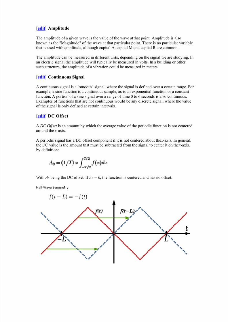
[edit] DC Offset
A DC O ff set is an amount by which the average value of the per iodic function is not centered
around the x-axis.
A per iodic signal has a DC offset component if it is not centered about the x-axis. In general,the DC value is the amount that must be subtracted from the signal to center it on the x-axis.
by def inition:
With A0 being the DC offset. If A0 = 0, the function is centered and has no offset.
Half -�
ave Symme�
ry

8/6/2019 Notes on Micro Controller and Digital Signal Processing
http://slidepdf.com/reader/full/notes-on-micro-controller-and-digital-signal-processing 28/70
Nonperiodic/Aperiodic Signals
The opposite of a periodic signal is an aperiodic signal. An aperiodic function never repeats,although technically an aperiodic function can be considered like a periodic function with aninfinite period. This chapter will formally introduce the fourier transform, will discuss some
of the properties of the transform, and then will talk about power spectral density functions.
[edit] Background
If we consider aperiodic signals, it turns out that we can generalize the Fourier Series suminto an integral named the Fourier Transform. The Fourier Transform is used similarly tothe Fourier Series, in that it converts a time-domain function into a frequency domainrepresentation. However, there are a number of differences:
1. Fourier Transf orm can work on Aperiodic Signals.
2. Fourier Transf orm is an inf inite sum of infinitesimal sinusoids.
3. Fourier Transf orm has an i nv erse transform, that allows f or conversion f rom the f requency
domain back to the time domain.
[edit] Fourier Transform
This operation can be perf ormed using this MATLAB command:
fft
The Fourier Transform is the following integral:
[edit] Inverse Fourier Transform
And the inverse transform is given by a similar integral:
Using these formulas, time-domain signals can be converted to and from the frequency
domain, as needed.
[edit] Partial Fraction Expansion
One of the most important tools when attempting to find the inverse fourier transform is theTheory of Partial Fractions. The theory of partial fractions allows a complicated fractionalvalue to be decomposed into a sum of small, simple fractions. This technique is highlyimportant when dealing with other transforms as well, such as the Laplace transform and theZ-Transform.

8/6/2019 Notes on Micro Controller and Digital Signal Processing
http://slidepdf.com/reader/full/notes-on-micro-controller-and-digital-signal-processing 29/70
ADVANTAGE & DISAD of FIR filter
The choice of an FIR design versus an IIR can spark much debate amoung designers. It is the
opinon of the author that new users of digital f ilters should star t out with FIR type f ilters.
This is recommended for the following reasons:
FIR filters can easily be designed f or constant phase delay and/or constant group delay (�
hich aff ects the
distortion of pass band signals with broadband characteristics)
Stability is inherent and limit cycling is not a problem as it is with IIR designs (This is provided the User
implements the filter with nonrecursive techniques)�
Round off errors can be controlled in a straightf orward fashion in order to�
eep their eff ects insignificant
The drawbacks of using anFIR are:
An FIR generally requires more stages than an IIR to obtain sharp filter bands.
Additional stages add to memory requirements and slow processing speed.
Designs that demand high performance usually justify an effor t to tradeoff FIR vs IIR f ilter
implementations. But for f irst time application it is recommended that aggressive f ilter design be avoided until one has the exper ience to avoid the var ious pitfalls that await you.
Finite impulse response
A f inite impulse response (FIR) f ilter is a type of a signal processing f ilter whose impulse
response (or response to any f inite length input) is of f i� it e duration, because it settles to zeroin f inite time. This is in contrast to inf inite impulse response (IIR ) f ilters, which have internal feedback and may continue to respond indef initely (usually decaying). Theimpulse response of an Nth-order discrete-time FIR f ilter (i.e. with a Kronecker delta impulse input) lasts for
N+1 samples, and then dies to zero.
Def inition

8/6/2019 Notes on Micro Controller and Digital Signal Processing
http://slidepdf.com/reader/full/notes-on-micro-controller-and-digital-signal-processing 30/70
A discrete-time FIR filter of order N. The top part is an N-stage delay line with N+1 taps. Each unit
delay is a z-1 operator in Z-transf orm notation.
The out put y of a linear time invar iant system is determined by convolving its input signal x with its impulse response b.
For a discrete-time FIR f ilter, the out put is a weighted sum of the current and a f inite number
of previous values of the input. The operation is descr i bed by the following equation, which
def ines the out put sequence y[n] in terms of its input sequence x[n]:
where:
y x [n] is the input signal,
y y [n] is the output signal,
y bi are the filt�
r co�
ffici�
nts, also� nown as t
p w
� ights, that make up the impulse response,
y N is the filter order; an Nth-order filter has (N + 1) terms on the right-hand side. The x [n i ]
in these terms are commonly ref erred to as t ps, based on the structure of a tapped delay
line that in many implementations or block diagrams provides the delayed inputs to the
multiplication operations. One may speak of a "5th order/6-tap filter", f or instance.
[edit] Properties
An FIR f ilter has a number of useful proper ties which sometimes make it preferable to an
inf inite impulse response (IIR ) f ilter. FIR f ilters:
y Require no f eedback. This means that any rounding errors are not compounded by summed
iterations. The same relative error occurs in each calculation. This also makes
implementation simpler.
y Are inherently stable. This is due to the fact that, because there is no required f eedback, all
the poles are located at the origin and thus are located within the unit circle.
y They can easily be designed to be linear phase by making the coefficient sequence
symmetric; linear phase, or phase change proportional to f requency, corresponds to equal
delay at all f requencies. This property is sometimes desired f or phase-sensitive applications,
f or example data communications, crossover filters, and mastering.
The main disadvantage of FIR f ilters is that considerably more computation power in a
general purpose processor is required compared to an IIR f ilter with similar sharpness or selectivity, especially when low frequency (relative to the sample rate) cutoffs are needed.
However many digital signal processors provide specialized hardware features to make FIR f ilters approximately as eff icient as IIR for many applications.
Inf inite impulse response
8/6/2019 Notes on Micro Controller and Digital Signal Processing
http://slidepdf.com/reader/full/notes-on-micro-controller-and-digital-signal-processing 31/70
Inf inite impulse response (IIR) is a proper ty of signal processing systems. Systems withthis proper ty are known as IIR s y st em s or, when dealing with f ilter systems, as IIR f il t er s. IIR systems have an impulse response function that is non-zero over an inf inite length of time.This is in contrast to f inite impulse response (FIR ) f ilters, which have f ixed-duration impulse
responses. The simplest analog IIR f ilter is anRC f ilter made up of a single resistor (R )feeding into a node shared with a singlecapacitor (C). This f ilter has an exponential impulse
response character ized by anRC time constant.
IIR f ilters may be implemented as either analog or digital f ilters. In digital IIR f ilters, theout put feedback is immediately apparent in the equations def ining the out put. Note that unlike FIR f ilters, in designing IIR f ilters it is necessary to carefully consider the "time zero" case[ itat ion needed ] in which the out puts of the f ilter have not yet been clear ly def ined.
Design of digital IIR f ilters is heavily dependent on that of their analog counterpar ts because
there are plenty of resources, works and straightforward design methods concerning analog
feedback f ilter design while there are hardly any for digital IIR f ilters. As a result, usually,
when a digital IIR f ilter is going to be implemented, an analog f ilter (e.g. Chebyshev f ilter ,
Butterwor th f ilter , Elli ptic f ilter ) is f irst designed and then is conver ted to a digital f ilter by
applying discretization techniques such as Bilinear transform or Impulse invar iance.
Example IIR f ilters include the Chebyshev f ilter , Butterwor th f ilter , and the Bessel f ilter .
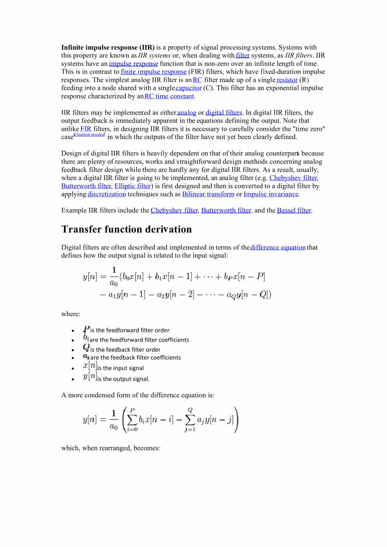
Transfer function deri ation
Digital f ilters are of ten descr i bed and implemented in terms of thedifference equation that def ines how the out put signal is related to the input signal:
where:
y is the f eedf orward filter order
y are the f eedf orward filter coefficients
y is the f eedback filter order
y are the f eedback filter coefficients
y is the input signal
y is the output signal.
A more condensed form of the difference equation is:
which, when rearranged, becomes:

8/6/2019 Notes on Micro Controller and Digital Signal Processing
http://slidepdf.com/reader/full/notes-on-micro-controller-and-digital-signal-processing 32/70
To f ind the transfer function of the f ilter, we f irst take the Z-transform of each side of the
above equation, where we use the time-shif t proper ty to obtain:
We def ine the transfer function to be:
Consider ing that in most IIR f ilter designs coeff icient is 1, the IIR f ilter transfer functiontakes the more traditional form:
[edit] Description of block diagram
Simple IIR filter block diagram
A typical block diagram of an IIR f ilter looks like the following. The z í 1
block is a unit delay. The coeff icients and number of feedback /feedforward paths are implementation-
dependent.

8/6/2019 Notes on Micro Controller and Digital Signal Processing
http://slidepdf.com/reader/full/notes-on-micro-controller-and-digital-signal-processing 33/70
[edit] Stability
The transfer function allows us to judge whether or not a system is bounded-input, bounded-out put (BIBO) stable. To be specif ic, the BIBO stability cr iter ia requires that the R OC of the
system includes the unit circle. For example, for a causal system, all poles of the transfer
function have to have an absolute value smaller than one. In other words, all poles must belocated within a unit circle in the z-plane.
The poles are def ined as the values of z which make the denominator of H ( z) equal to 0:
Clear ly, if then the poles are not located at the or igin of the z-plane. This is incontrast to the FIR f ilter where all poles are located at the or igin, and is therefore always
stable.
IIR f ilters are sometimes preferred over FIR f ilters because an IIR f ilter can achieve a muchsharper transition region roll-off than FIR f ilter of the same order.
[edit] Example
Let the transfer function of a f ilter H be
with ROC a < | z | and 0 < a < 1
which has a pole at a, is stable and causal. The time-domain impulse response is
h(n) = anu(n)
which is non-zero for n > = 0.
Discrete Four ier transform
In mathematics, the discrete Fourier transform (DFT) is a specif ic k ind of discretetransform, used in Four ier analysis. It transforms one function into another, which is called
the f requency d omain representation, or simply the DF T , of the or iginal function (which isof ten a function in the time domain). But the DFT requires an input function that is d i scret e and whose non-zero values have a limited ( f init e) duration. Such inputs are of ten created by
sampling a continuous function, like a person's voice. Unlike thediscrete-time Four ier
transform (DTFT), it only evaluates enough frequency components to reconstruct the f initesegment that was analyzed. Using the DFT implies that the f inite segment that is analyzed isone per iod of an inf initely extended per iodic signal; if this is not actually true, awindow
function has to be used to reduce the ar tifacts in the spectrum. For the same reason, the
inverse DFT cannot reproduce the entire time domain, unless the input happens to be per iodic
8/6/2019 Notes on Micro Controller and Digital Signal Processing
http://slidepdf.com/reader/full/notes-on-micro-controller-and-digital-signal-processing 34/70
(forever). Therefore it is of ten said that the DFT is a transform for Four ier analysis of f inite-domain discrete-time functions. The sinusoidal basis functions of the decomposition have the
same proper ties.
The input to the DFT is a f inite sequence of real or complex numbers (with more abstract generalizations discussed below), mak ing the DFT ideal for processing information stored in
computers. In par ticular, the DFT is widely employed in signal processing and related f ieldsto analyze the frequencies contained in a sampledsignal, to solve par tial differential equations, and to perform other operations such asconvolutions or multi plying large integers.A key enabling factor for these applications is the fact that the DFT can be computed
eff iciently in practice using a fast Four ier transform (FFT) algor ithm.
FFT algor ithms are so commonly employed to compute DFTs that the term "FFT" is of tenused to mean "DFT" in colloquial settings. Formally, there is a clear distinction: "DFT" refers
to a mathematical transformation or function, regardless of how it is computed, whereas
"FFT" refers to a specif ic family of algor ithms for computing DFTs. The terminology isfur ther blurred by the (now rare) synonymf inite Four ier transform for the DFT, which
apparently predates the term "fast Four ier transform" (Cooley et al., 1969) but has the same
initialism.
Properties
[edit] Completeness
The discrete Four ier transform is an inver ti ble, linear transformation
with C denoting the set of complex numbers. In other words, for any N > 0, an N -dimensional complex vector has a DFT and an IDFT which are in turn N -dimensional complex vectors.
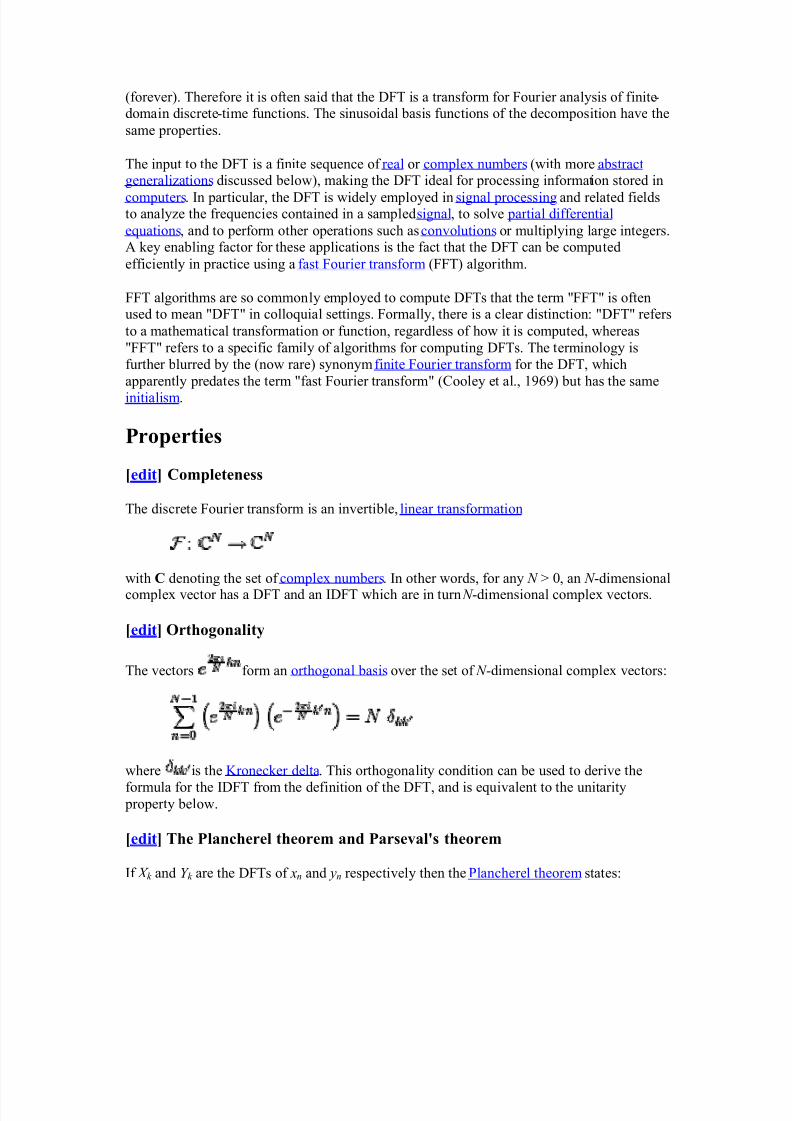
[edit] Orthogonality
The vectors form an or thogonal basis over the set of N -dimensional complex vectors:
where is the Kronecker delta. This or thogonality condition can be used to der ive the
formula for the IDFT from the def inition of the DFT, and is equivalent to the unitar ity proper ty below.
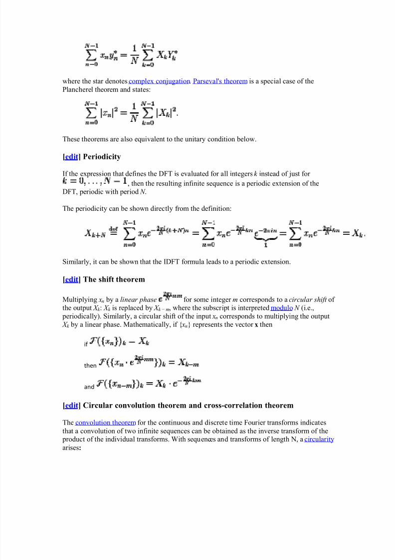
[edit] The Plancherel theorem and Parseval's theorem
If X k and Y k are the DFTs of xn and yn respectively then the Plancherel theorem states:
8/6/2019 Notes on Micro Controller and Digital Signal Processing
http://slidepdf.com/reader/full/notes-on-micro-controller-and-digital-signal-processing 35/70
8/6/2019 Notes on Micro Controller and Digital Signal Processing
http://slidepdf.com/reader/full/notes-on-micro-controller-and-digital-signal-processing 36/70
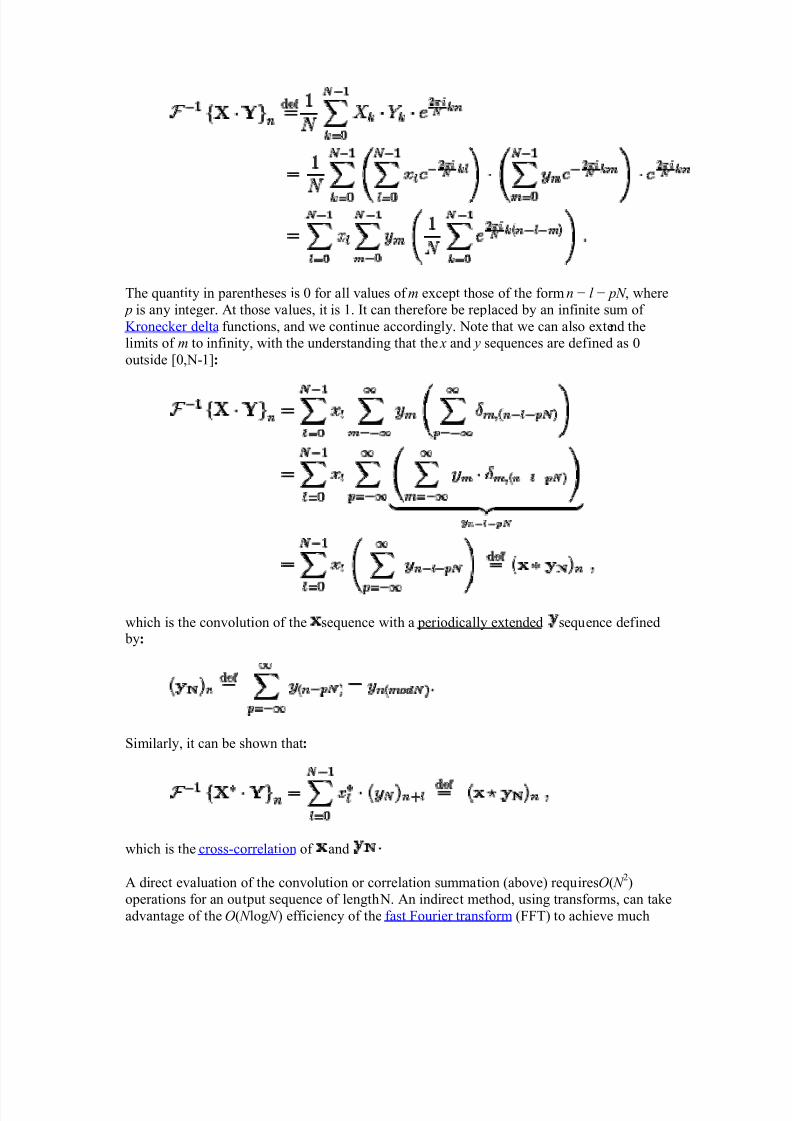
The quantity in parentheses is 0 for all values of m except those of the formn í l í p N , where
p is any integer. At those values, it is 1. It can therefore be replaced by an inf inite sum of
Kronecker delta functions, and we continue accordingly. Note that we can also extend the
limits of m to inf inity, with the understanding that the x and y sequences are def ined as 0
outside [0,N-1]:
which is the convolution of the sequence with a per iodically extended sequence def ined by:
Similar ly, it can be shown that:
which is the cross-correlation of and
A direct evaluation of the convolution or correlation summation (above) requiresO( N 2)
operations for an out put sequence of length N. An indirect method, using transforms, can take
advantage of the O( N log N ) eff iciency of the fast Four ier transform (FFT) to achieve much

8/6/2019 Notes on Micro Controller and Digital Signal Processing
http://slidepdf.com/reader/full/notes-on-micro-controller-and-digital-signal-processing 37/70
better performance. Fur thermore, convolutions can be used to eff iciently compute DFTs viaR ader's FFT algor ithm and Bluestein's FFT algor ithm.
Methods have also been developed to use circular convolution as par t of an eff icient process
that achieves normal (non-circular) convolution with an or sequence potentially muchlonger than the practical transform size (N). Two such methods are called over lap-save and
over lap-add.[1]
[edit] Convolution theorem duality
It can also be shown that:
which is the circular convolution of and .
[edit] Trigonometric interpolation polynomial
The tr igonometr ic interpolation polynomial
f or N even ,
f or N odd,
where the coeff icients X k are given by the DFT of xn above, satisf ies the interpolation
proper ty p(2n / N ) = xn for .
For even N , notice that the Nyquist component is handled specially.
This interpolation is not unique: aliasing implies that one could add N to any of the complex-sinusoid frequencies (e.g. changinge í it to ei( N í 1)t ) without changing the interpolation
proper ty, but giving d i ff erent values in between the xn points. The choice above, however, istypical because it has two useful proper ties. First, it consists of sinusoids whose frequencies
have the smallest possi ble magnitudes: the interpolation is bandlimited. Second, if the xn arereal numbers, then p(t ) is real as well.
In contrast, the most obvious tr igonometr ic interpolation polynomial is the one in which the
frequencies range from 0 to N í 1 (instead of roughly í N / 2 to + N / 2 as above), similar tothe inverse DFT formula. This interpolation doesnot minimize the slope, and is not generallyreal-valued for real xn; its use is a common mistake.

8/6/2019 Notes on Micro Controller and Digital Signal Processing
http://slidepdf.com/reader/full/notes-on-micro-controller-and-digital-signal-processing 38/70
[edit] The unitary DFT
Another way of look ing at the DFT is to note that in the above discussion, the DFT can be
expressed as a Vandermonde matr ix:
where
is a pr imitive Nth root of unity. The inverse transform is then given by the inverse of the
above matr ix:
With unitary normalization constants , the DFT becomes a unitary transformation,
def ined by a unitary matr ix:
where det ( ) is the determinant function. The determinant is the product of the eigenvalues,
which are always or as descr i bed below. In a real vector space, a unitary
transformation can be thought of as simply a r igid rotation of the coordinate system, and all of the proper ties of a r igid rotation can be found in the unitary DFT.
The or thogonality of the DFT is now expressed as anor thonormality condition (which ar isesin many areas of mathematics as descr i bed inroot of unity):
If is def ined as the unitary DFT of the vector then

8/6/2019 Notes on Micro Controller and Digital Signal Processing
http://slidepdf.com/reader/full/notes-on-micro-controller-and-digital-signal-processing 39/70
and the Plancherel theorem is expressed as:
If we view the DFT as just a coordinate transformation which simply specifies thecomponents of a vector in a new coordinate system, then the above is just the statement thatthe dot product of two vectors is preserved under a unitary DFT transformation. For thespecial case , this implies that the length of a vector is preserved as well²this is justParseval's theorem:
[edit] Expressing the inverse DFT in terms of the DFT
A useful property of the DFT is that the inverse DFT can be easily expressed in terms of the(forward) DFT, via several well-known "tricks". (For example, in computations, it is oftenconvenient to only implement a fast Fourier transform corresponding to one transformdirection and then to get the other transform direction from the first.)
First, we can compute the inverse DFT by reversing the inputs:
(As usual, the subscripts are interpreted modulo N ; thus, for n = 0, we have x N í 0 = x0.)
Second, one can also conjugate the inputs and outputs:
Third, a variant of this conjugation trick, which is sometimes preferable because it requiresno modification of the data values, involves swapping real and imaginary parts (which can bedone on a computer simply by modifying pointers). Define swap( xn) as xn with its real andimaginary parts swapped²that is, if xn = a + bi then swap( xn) is b + ai. Equivalently,
swap( xn) equals . Then
That is, the inverse transform is the same as the forward transform with the real andimaginary parts swapped for both input and output, up to a normalization (Duhamel et al.,1988).
The conjugation trick can also be used to define a new transform, closely related to the DFT,
that is involutary ²that is, which is its own inverse. In particular, is
clearly its own inverse: . A closely related involutary transformation (by a

8/6/2019 Notes on Micro Controller and Digital Signal Processing
http://slidepdf.com/reader/full/notes-on-micro-controller-and-digital-signal-processing 40/70
factor of (1+i) /¥2) is , since the (1 + i) factors in
cancel the 2. For real inputs , the real par t of is none other than the
discrete Har tley transform, which is also involutary.
[edit] Eigenvalues and eigenvectors
The eigenvalues of the DFT matr ix are simple and well-known, whereas the eigenvectors are
complicated, not unique, and are the sub ject of ongoing research.
Consider the unitary form def ined above for the DFT of length N , where
This matr ix satisf ies the matr ix polynomial equation:
This can be seen from the inverse proper ties above: operating twice gives the or iginal datain reverse order, so operating four times gives back the or iginal data and is thus the
identity matr ix. This means that the eigenvalues satisfy the equation:
4
= 1.
Therefore, the eigenvalues of are the four th roots of unity: is +1, í1, +i, or íi.
Since there are only four distinct eigenvalues for this matr ix, they have some
multi plicity. The multi plicity gives the number of linear ly independent eigenvectors
corresponding to each eigenvalue. (Note that there are N independent eigenvectors; a unitarymatr ix is never defective.)
Pr
p
r
i j
f Dij cr
F
uri
r Tr
k
l j f
rm
As a special case of general Four ier transform, the discrete time transform shares all proper ties (and their proofs) of the Four ier transform discussed above, except now some of
these proper ties may take different forms. In the following, we always assume
and .
y Linm n
rity

8/6/2019 Notes on Micro Controller and Digital Signal Processing
http://slidepdf.com/reader/full/notes-on-micro-controller-and-digital-signal-processing 41/70
y Ti o Shifting
Proof:
If we let , the above becomes
y Ti
R
v
rs
l
y Fr
qu
ncy Shifting
y Diff
r
ncing
Differencing is the discrete-time counterpar t of differentiation.

8/6/2019 Notes on Micro Controller and Digital Signal Processing
http://slidepdf.com/reader/full/notes-on-micro-controller-and-digital-signal-processing 42/70
Proof:
y Diff
r
nti tion in fr
qu
ncy
proof: Diff erentiating the definition of discrete Fourier transf orm with respect to , we get
y Convolution Th
or
s
The convolution theorem states that convolution in time domain corresponds tomulti plication in frequency domain and vice versa:

8/6/2019 Notes on Micro Controller and Digital Signal Processing
http://slidepdf.com/reader/full/notes-on-micro-controller-and-digital-signal-processing 43/70
Recall that the convolution of periodic signals and is
Here the convolution of periodic spectra and is similarly defined as
Proof of (a):
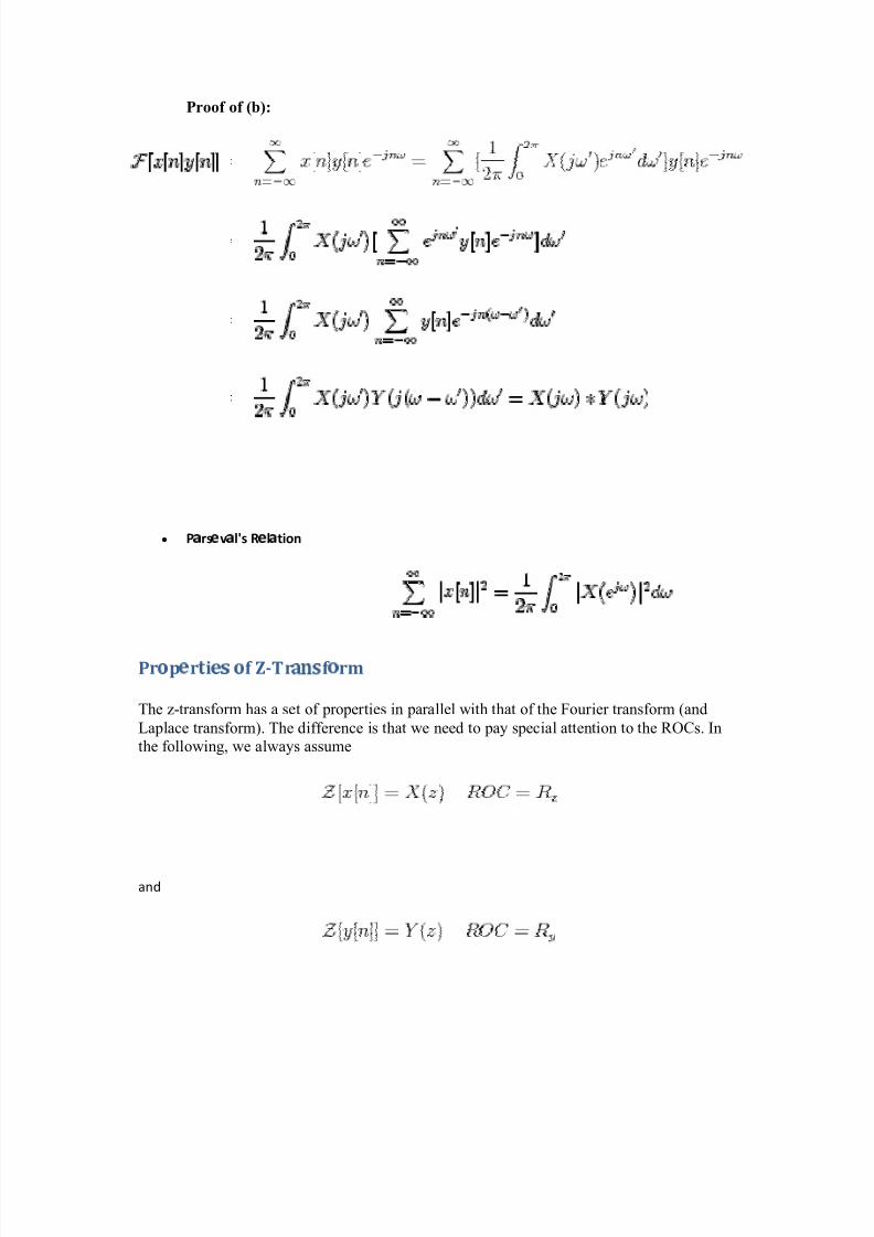
8/6/2019 Notes on Micro Controller and Digital Signal Processing
http://slidepdf.com/reader/full/notes-on-micro-controller-and-digital-signal-processing 44/70
Proof of (b):
y P z rs { v z l's R { l z tion
Pr|
p}
r~
i} |
f Z-Tr
f
| rm
The z-transform has a set of proper ties in parallel with that of the Four ier transform (and
Laplace transform). The difference is that we need to pay special attention to the R OCs. In
the following, we always assume
and

8/6/2019 Notes on Micro Controller and Digital Signal Processing
http://slidepdf.com/reader/full/notes-on-micro-controller-and-digital-signal-processing 45/70
y Lin
rity
While it is obvious that the ROC of the linear combination of and should be the
intersection of the their individual ROCs in which both and exist,
note that in some cases the ROC of the linear combination could be larger than .
For example, f or both and , the ROC is
, but the ROC of their diff erence is the
entire z-plane.
y Ti
Shifting
Proof:
D
efine , we have and

8/6/2019 Notes on Micro Controller and Digital Signal Processing
http://slidepdf.com/reader/full/notes-on-micro-controller-and-digital-signal-processing 46/70
The new ROC is the same as the old one except the possible addition/deletion of the origin
or infinity as the shift may change the duration of the signal.
y Ti
xp
nsion (Sc
ling)
The discrete signal cannot be continuously scaled in time as has to be an integer
(f or a non-integer is zero). Theref ore is defined as
Ex� �
pl�
: If is ramp
1 2 3 4 5 6
1 2 3 4 5 6
then the expanded version is
1 2 3 4 5 6
0.5 1 1.5 2 2.5 3
1 2 3
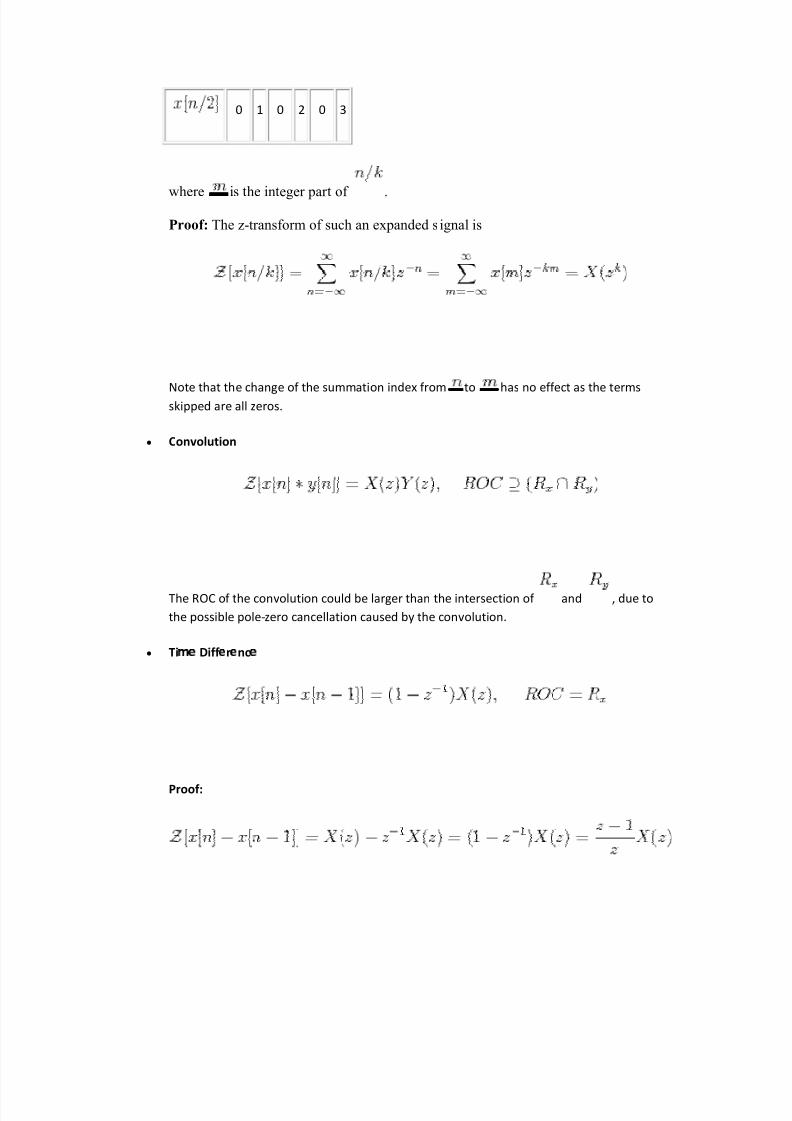
8/6/2019 Notes on Micro Controller and Digital Signal Processing
http://slidepdf.com/reader/full/notes-on-micro-controller-and-digital-signal-processing 47/70
0 1 0 2 0 3
where is the integer par t of .
Proof : The z-transform of such an expanded signal is
N
ote that the change of the summation index f rom to has no eff ect as the terms skipped are all zeros.
y Convolution
The ROC of the convolution could be larger than the intersection of and , due to
the possible pole-zero cancellation caused by the convolution.
y Ti� �
Diff �
r�
nc�
Proof:
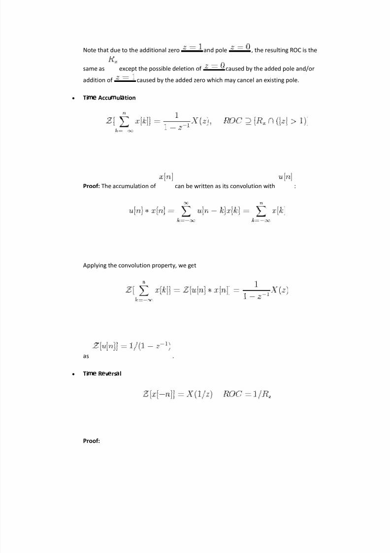
8/6/2019 Notes on Micro Controller and Digital Signal Processing
http://slidepdf.com/reader/full/notes-on-micro-controller-and-digital-signal-processing 48/70
Note that due to the additional zero and pole , the resulting ROC is the
same as except the possible deletion of caused by the added pole and/or
addition of caused by the added zero which may cancel an existing pole.
y Ti � Accu � ul tion
Proof: The accumulation of can be written as its convolution with :
Applying the convolution property, we get
as .
y Ti R v rs l
Proof:

8/6/2019 Notes on Micro Controller and Digital Signal Processing
http://slidepdf.com/reader/full/notes-on-micro-controller-and-digital-signal-processing 49/70
where .
y Sc ling in Z-do
in
Proof:
In particular, if , the above becomes
The multiplication by to corresponds to a rotation by angle in the z-plane, i.e.,
a f requency shift by . The rotation is either clockwise ( ) or counter clockwise (
) corresponding to, respectively, either a left-shift or a right shift in f requency
domain. The property is essentially the same as the f requency shifting property of discrete
Fourier transf orm.
y Conjug
tion
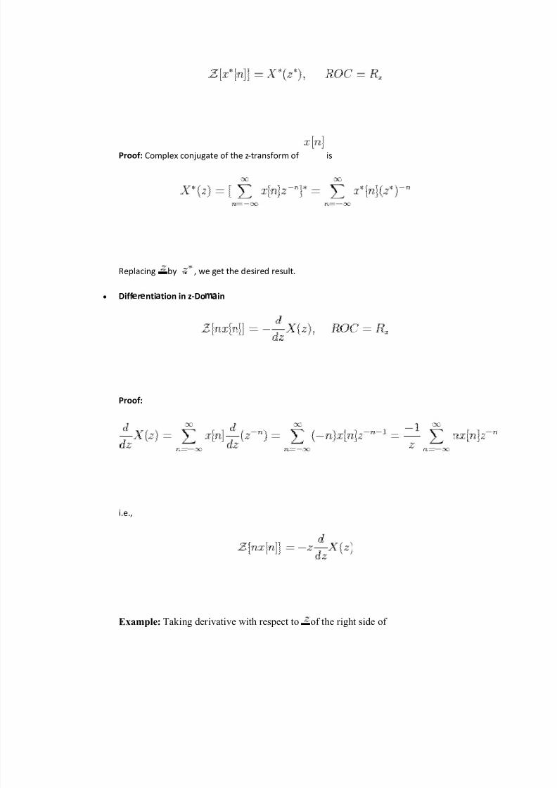
8/6/2019 Notes on Micro Controller and Digital Signal Processing
http://slidepdf.com/reader/full/notes-on-micro-controller-and-digital-signal-processing 50/70
Proof: Complex con jugate of the z-transf orm of is
Replacing by , we get the desired result.
y Diff
r
nti tion in z-Do
� in
Proof:
i.e.,
Example: Tak ing der ivative with respect to of the r ight side of

8/6/2019 Notes on Micro Controller and Digital Signal Processing
http://slidepdf.com/reader/full/notes-on-micro-controller-and-digital-signal-processing 51/70
we get
Due to the property of diff erentiation in z-domain, we have
Note that f or a diff erent ROC , we have
8051 Tutorial: Addressing Modes
An "addressing mode" refers to how you are addressing a given memory location. Insummary, the addressing modes are as follows, with an example of each:
Immediate Addressing MOV A,#20h
Direct Addressing MOV A,30h
Indirect Addressing MOV A,@R 0
External Direct MOVX A,@DPTR
Code Indirect MOVC A,@A+DPTR
Each of these addressing modes provides impor tant f lexi bility.
Immediate Addressing

8/6/2019 Notes on Micro Controller and Digital Signal Processing
http://slidepdf.com/reader/full/notes-on-micro-controller-and-digital-signal-processing 52/70
Immediate addressing is so-named because the value to be stored in memory immediatelyfollows the operation code in memory. That is to say, the instruction itself dictates what valuewill be stored in memory.
For example, the instruction:
MOV A,#20h
This instruction uses Immediate Addressing because the Accumulator will be loaded with thevalue that immediately follows; in this case 20 (hexidecimal).
Immediate addressing is very fast since the value to be loaded is included in the instruction.However, since the value to be loaded is fixed at compile-time it is not very flexible.
Direct Addressing
Direct addressing is so-named because the value to be stored in memory is obtained bydirectly retrieving it from another memory location. For example:
MOV A,30h
This instruction will read the data out of Internal RAM address 30 (hexidecimal) and store itin the Accumulator.
Direct addressing is generally fast since, although the value to be loaded isnt included in theinstruction, it is quickly accessable since it is stored in the 8051s Internal RAM. It is alsomuch more flexible than Immediate Addressing since the value to be loaded is whatever isfound at the given address--which may be variable.
Also, it is important to note that when using direct addressing any instruction which refers toan address between 00h and 7Fh is referring to Internal Memory. Any instruction whichrefers to an address between 80h and FFh is referring to the SFR control registers that controlthe 8051 microcontroller itself.
The obvious question that may arise is, "If direct addressing an address from 80h throughFFh refers to SFRs, how can I access the upper 128 bytes of Internal RAM that are availableon the 8052?" The answer is: You cant access them using direct addressing. As stated, if youdirectly refer to an address of 80h through FFh you will be referring to an SFR. However,you may access the 8052s upper 128 bytes of RAM by using the next addressing mode,"indirect addressing."
Indirect Addressing
Indirect addressing is a very powerful addressing mode which in many cases provides anexceptional level of flexibility. Indirect addressing is also the only way to access the extra128 bytes of Internal RAM found on an 8052.
Indirect addressing appears as follows:
MOV A,@R0
8/6/2019 Notes on Micro Controller and Digital Signal Processing
http://slidepdf.com/reader/full/notes-on-micro-controller-and-digital-signal-processing 53/70
This instruction causes the 8051 to analyze the value of the R0 register. The 8051 will thenload the accumulator with the value from Internal RAM which is found at the addressindicated by R0.
For example, lets say R0 holds the value 40h and Internal RAM address 40h holds the value67h. When the above instruction is executed the 8051 will check the value of R0. Since R0
holds 40h the 8051 will get the value out of Internal RAM address 40h (which holds 67h) andstore it in the Accumulator. Thus, the Accumulator ends up holding 67h.
Indirect addressing always refers to Internal RAM; it never refers to an SFR. Thus, in a prior example we mentioned that SFR 99h can be used to write a value to the serial port. Thus onemay think that the following would be a valid solution to write the value 1 to the serial port:
MOV R0,#99h ;Load the address of the serial portMOV @R0,#01h ;Send 01 to the serial port -- WRONG!!
This is not valid. Since indirect addressing always refers to Internal RAM these twoinstructions would write the value 01h to Internal RAM address 99h on an 8052. On an 8051these two instructions would produce an undefined result since the 8051 only has 128 bytesof Internal RAM.
External Direct
External Memory is accessed using a suite of instructions which use what I call "ExternalDirect" addressing. I call it this because it appears to be direct addressing, but it is used toaccess external memory rather than internal memory.
There are only two commands that use External Direct addressing mode:
MOVX A,@DPTR MOVX @DPTR,A
As you can see, both commands utilize DPTR. In these instructions, DPTR must first beloaded with the address of external memory that you wish to read or write. Once DPTR holdsthe correct external memory address, the first command will move the contents of thatexternal memory address into the Accumulator. The second command will do the opposite: itwill allow you to write the value of the Accumulator to the external memory address pointedto by DPTR.
External Indirect
External memory can also be accessed using a form of indirect addressing which I callExternal Indirect addressing. This form of addressing is usually only used in relatively small
projects that have a very small amount of external RAM. An example of this addressingmode is:
MOVX @R0,A
Once again, the value of R0 is first read and the value of the Accumulator is written to thataddress in External RAM. Since the value of @R0 can only be 00h through FFh the project
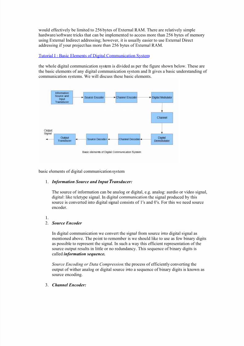
8/6/2019 Notes on Micro Controller and Digital Signal Processing
http://slidepdf.com/reader/full/notes-on-micro-controller-and-digital-signal-processing 54/70
would effectively be limited to 256 bytes of External R AM. There are relatively simplehardware/sof tware tr icks that can be implemented to access more than 256 bytes of memory
using External Indirect addressing; however, it is usually easier to use External Direct addressing if your pro ject has more than 256 bytes of External R AM.
Tutor ial I : Basic Elements of Digital Communication System
the whole digital communication system is divided as per the f igure shown below. These are
the basic elements of any digital communication system and It gives a basic understanding of communication systems. We will discuss these basic elements.
basic elements of digital communication system
1. Informati on S ource and Input � ransducer:
The source of information can be analog or digital, e.g. analog: aurdio or video signal,digital: like teletype signal. In digital communication the signal produced by thissource is conver ted into digital signal consists of 1s and 0s. For this we need source
encoder.
1. 2. S ource E ncoder
In digital communication we conver t the signal from source into digital signal as
mentioned above. The point to remember is we should like to use as few binary digitsas possi ble to represent the signal. In such a way this eff icient representation of thesource out put results in little or no redundancy. This sequence of binary digits iscalled i nformati on sequence.
S our ce E ncod in g or Data C om pre ssion: the process of eff iciently conver ting the
out put of wither analog or digital source into a sequence of binary digits is known as
source encoding.
3. Channel E ncoder:

8/6/2019 Notes on Micro Controller and Digital Signal Processing
http://slidepdf.com/reader/full/notes-on-micro-controller-and-digital-signal-processing 55/70
The information sequence is passed through the channel encoder. The purpose of thechannel encoder is to introduced, in controlled manner, some redundancy in the
binary information sequence that can be used at the receiver to overcome the effectsof noise and interference encountered in the transmission on the signal through thechannel.
e.g. take k bits of the information sequence and map that k bits to unique n bitsequence called code word. The amount of redundancy introduced is measured by theratio n/k and the reciprocal of this ratio (k/n) is known as r at e o f cod e or cod e r at e.
4. Digital M odul ator:
The binary sequence is passed to digital modulator which in turns convert thesequence into electric signals so that we can transmit them on channel (we will seechannel later). The digital modulator maps the binary sequences into signal waveforms , for example if we represent 1 by sin x and 0 by cos x then we will transmit sinx for 1 and cos x for 0. ( a case similar to BPSK )
5. C � annel :
The communication channel is the physical medium that is used for transmittingsignals from transmitter to receiver. In wireless system, this channel consists of atmosphere , for traditional telephony, this channel is wired , there are opticalchannels, under water acoustic cahnenls etc.
we further discriminate this channels on the basis of their property and characteristics,like AWGN channel etc.
6. Digital Demodul ator:
The digital demodulator processes the channel corrupted transmitted waveform andreduces the waveform to the sequence of numbers that represents estimates of thetransmitted data symbols.
7. C �
annel Decoder:
This sequence of numbers then passed through the channel decoder which attempts toreconstruct the original information sequence from the knowledge of the code used bythe channel encoder and the redundancy contained in the received data
The average �
robabi l ity of a bit error at the output of the decoder is a measure of
the performance of the demodul ator ± decoder combination. THI
�
I
�
THE MOS T I MPORTANT PO INT, W e wi ll discuss a l ot about this B E R (Bit Error Rate) stuff
in coming posts.
8. S ource Decoder
At the end, if an analog signal is desired then source decoder tries to decode thesequence from the knowledge of the encoding algorithm. And which results in theapproximate replica of the input at the transmitter end

8/6/2019 Notes on Micro Controller and Digital Signal Processing
http://slidepdf.com/reader/full/notes-on-micro-controller-and-digital-signal-processing 56/70
9. Output Transducer:
Finally we get the desired signal in desired format analog or digital.
The point worth noting are :
1. the source coding algorithm plays important role in higher code rate2. the channel encoder introduced redundancy in data3. the modulation scheme plays important role in deciding the data rate and immunity of
signal towards the errors introduced by the channel4. channel introduced many types of errors like multi path, errors due to thermal noise
etc.5. the demodulator and decoder should provide high BER.
Advantage of Digital over analog signal processing
1.A Digital programmable system allows flexibility in reconfiguring the digitalsignal processingoperation simply by changing the program. Reconfigurationof analog system usually impliesredesign of hardware followed by testing andverification to see that if operates properly.2.Digital system provide much better control of accuracy requirements.3.Digital system are easily stored on magnetic media without loss of signal«««« beyond thatintroduce in A/D conversion. As a consequence, thesignals become transportable and can beprocessed offline in a remotelaboratory.4.Digital signal processing method also allows for the implementation of moresophisticated.5.In some cases a digital implementation of signal processing system ischeaper than its analog counterpart

8/6/2019 Notes on Micro Controller and Digital Signal Processing
http://slidepdf.com/reader/full/notes-on-micro-controller-and-digital-signal-processing 57/70
Copyright (C) 2
5 Güner Arslan 351M Digital Signal Processing 12
Decimation-In-Frequency FF Algorithm
� he DF equation
� Split the DF equation into even and odd frequency indexes
� Substitute variables to get
� Similarly for odd-numbered frequencies
? A §
!
!
1N
n
nkNW]n[xkX
? A §§§
!
!
!
!!1N
2 /Nn
r2nN
12 /N
n
r2nN
1N
n
r2nN W]n[xW]n[xW]n[xr2X
? A
§§§
!
!
! !!
12 /N
n
nr
2 /N
12 /N
n
r22 /Nn
N
12 /N
n
r2n
N W]2 /Nn[x]n[xW]2 /Nn[xW]n[xr2X
? A §
!
!12 /N
n
1r2n2 /NW]2 /Nn[x]n[x1r2X

8/6/2019 Notes on Micro Controller and Digital Signal Processing
http://slidepdf.com/reader/full/notes-on-micro-controller-and-digital-signal-processing 58/70

8/6/2019 Notes on Micro Controller and Digital Signal Processing
http://slidepdf.com/reader/full/notes-on-micro-controller-and-digital-signal-processing 59/70
filter increases, and thus its component count, the effect of variable component errors isgreatly magnified. In digital filters, the coefficient values are stored in computer memory,making them far more stable and predictable.[8]
Because the coefficients of digital filters are definite, they can be used to achieve much morecomplex and selective designs ± specifically with digital filters, one can achieve a lower
passband ripple, faster transition, and higher stopband attenuation than is practical withanalog filters. Even if the design could be achieved using analog filters, the engineering costof designing an equivalent digital filter would likely be much lower. Furthermore, one canreadily modify the coefficients of a digital filter to make an adaptive filter or a user-controllable parametric filter. While these techniques are possible in an analog filter, they areagain considerably more difficult.
Digital filters can be used in the design of finite impulse response filters. Analog filters donot have the same capability, because finite impulse response filters require delay elements.
Digital filters rely less on analog circuitry, potentially allowing for a better signal-to-noiseratio. A digital filter will introduce noise to a signal during analog low pass filtering, analog
to digital conversion, digital to analog conversion and may introduce digital noise due toquantization. With analog filters, every component is a source of thermal noise (such asJohnson noise), so as the filter complexity grows, so does the noise.
However, digital filters do introduce a higher fundamental latency to the system. In an analogfilter, latency is often negligible; strictly speaking it is the time for an electrical signal to
propagate through the filter circuit. In digital filters, latency is a function of the number of delay elements in the system.
Digital filters also tend to be more limited in bandwidth than analog filters. High bandwidthdigital filters require expensive ADC/DACs and fast computer hardware for processing.
In very simple cases, it is more cost effective to use an analog filter. Introducing a digitalfilter requires considerable overhead circuitry, as previously discussed, including two low
pass analog filters.

8/6/2019 Notes on Micro Controller and Digital Signal Processing
http://slidepdf.com/reader/full/notes-on-micro-controller-and-digital-signal-processing 60/70
8051
A micro-controller can be compared to a small stand alone computer, it is a very
powerful device, which is capable of executing a series of pre-programmed tasks and
interacting with other hardware devices. Being packed in a tiny integrated circuit (IC)
whose size and weight is usually negligible, it is becoming the perfect controller for
robots or any machines requiring some kind of intelligent automation. A single
microcontroller can be sufficient to control a small mobile robot, an automatic washer
machine or a security system. Any microcontroller contains a memory to store the
program to be executed, and a number of input/output lines that can be used to interact
with other devices, like reading the state of a sensor or controlling a motor.
Nowadays, microcontrollers are so cheap and easily available that it is common to use
them instead of simple logic circuits like counters for the sole purpose of gaining some
design flexibility and saving some space. Some machines and robots will even rely on a
multitude of microcontrollers, each one dedicated to a certain task. Most recent
microcontrollers are 'In System Programmable', meaning that you can modify the
program being executed, without removing the microcontroller from its place.
Today, microcontrollers are an indispensable tool for the robotics hobbyist as well as for
the engineer. Starting in this field can be a little difficult, because you usually can't
understand how everything works inside that integrated circuit, so you have to study the
system gradually, a small part at a time, until you can figure out the whole image and
understand how the system works.
The 80 is the name of a big family of microcontrollers. This figures shows the main
features and components that the designer can interact with
a block diagram of the 8051 main components.

8/6/2019 Notes on Micro Controller and Digital Signal Processing
http://slidepdf.com/reader/full/notes-on-micro-controller-and-digital-signal-processing 61/70
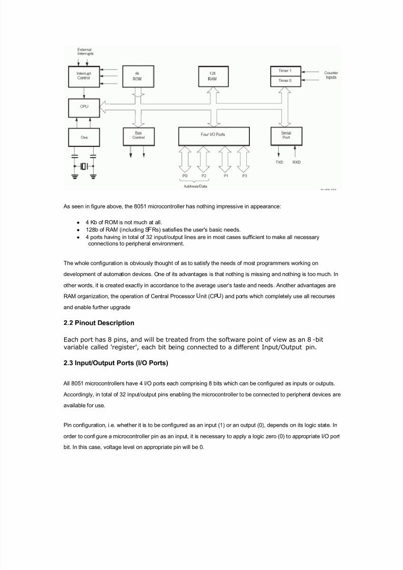
8/6/2019 Notes on Micro Controller and Digital Signal Processing
http://slidepdf.com/reader/full/notes-on-micro-controller-and-digital-signal-processing 62/70

8/6/2019 Notes on Micro Controller and Digital Signal Processing
http://slidepdf.com/reader/full/notes-on-micro-controller-and-digital-signal-processing 63/70
Similar ly, in order to configure a microcontroller pin as an input, it is necessary to apply a logic one (1) to
appropr iate por t. In this case, voltage level on appropr iate pin will be 5V (as is the case with any TTL input). This
may seem conf using but don't loose your patience. It all becomes clear after studying simple electronic circuits
connected to an I/O pin.
2.4 Memory Organization
The 8051 has two types of memory and these are Program Memory andData Memory. Program Memory (ROM)
is used to permanently save the program being executed, while Data Memory (R AM) is used f or temporar ily
stor ing data and intermediate results created and used dur ing the operation of the microcontroller . Depending on
the model in use (we are still talking about the 8051 microcontroller f amily in general) at most a f ewKb of ROM
and 128 or 256 bytes of R AM is used. However«
All 8051 microcontrollers have a 16-bit addressing bus and are capable of addressing 64 kb memory. It is neither
a mistake nor a big ambition of engineers who were working on basic core development. It is a matter of smar tmemory organization which makes these microcontrollers a real ³programmers¶ goody³.
Impulse response
In signal processing, the impulse response, or impulse response function (IRF), of adynamic system is its output when presented with a brief input signal, called an impulse.More generally, an impulse response refers to the reaction of any dynamic system in responseto some external change. In both cases, the impulse response describes the reaction of the
system as a function of time (or possibly as a function of some other independent variable that parameterizes the dynamic behavior of the system).
For example, the dynamic system might be a planetary system in orbit around a star ; theexternal influence in this case might be another massive object arriving from elsewhere in thegalaxy; the impulse response is the change in the motion of the planetary system caused byinteraction with the new object.
In all these cases, the 'dynamic system' and its 'impulse response' may refer to actual physicalobjects, or to a mathematical system of equations describing these objects
Practical applicationsIn practical systems, it is not possible to produce a perfect impulse to serve as input for testing; therefore, a brief pulse is sometimes used as an approximation of an impulse.Provided that the pulse is short enough compared to the impulse response, the result will beclose to the true, theoretical, impulse response. In many systems, however, driving with avery short strong pulse may drive the system into a nonlinear regime, so instead the system isdriven with a pseudo-random sequence, and the impulse response is computed from the inputand output signals.[1]

8/6/2019 Notes on Micro Controller and Digital Signal Processing
http://slidepdf.com/reader/full/notes-on-micro-controller-and-digital-signal-processing 64/70
[edit] Loudspeakers
An application that demonstrates this idea was the development of impulse responseloudspeaker testing in the 1970s. Loudspeakers suffer from phase inaccuracy, a defect unlikeother measured properties such as frequency response. Phase inaccuracy is caused by smalldelayed sounds that are the result of resonance, energy storage in the cone, the internal
volume, or the enclosure panels vibrating. Measuring the impulse response, which is a direct plot of this "time-smearing," provided a tool for use in reducing resonances by the use of improved materials for cones and enclosures, as well as changes to the speaker crossover.The need to limit input amplitude to maintain the linearity of the system led to the use of inputs such as pseudo-random maximum length sequences, and to the use of computer
processing to derive the impulse response. [2]
[edit] Digital filtering
Impulse response is a very important concept in the design of digital filters for audio processing, because digital filters can differ from 'real' filters in often having a pre-echo,which the ear is not accustomed to.
[edit] Electronic processing
Impulse response analysis is a major facet of radar , ultrasound imaging, and many areas of digital signal processing. An interesting example would be broadband internet connections.DSL/Broadband services use adaptive equalisation techniques to help compensate for signaldistortion and interference introduced by the copper phone lines used to deliver the service.
[edit] Control systems
In control theory the impulse response is the response of a system to a Dirac delta input. This
proves useful in the analysis of dynamic systems: the Laplace transform of the delta functionis 1, so the impulse response is equivalent to the inverse Laplace transform of the system'stransfer function.
[edit] Acoustic and audio applications
In acoustic and audio applications, impulse responses enable the acoustic characteristics of alocation, such as a concert hall, to be captured. Various commercial packages are availablecontaining impulse responses from specific locations, ranging from small rooms to largeconcert halls. These impulse responses can then be utilized in convolution reverb applicationsto enable the acoustic characteristics of a particular location to be applied to target audio.[3]
[edit] Economics
In economics, and especially in contemporary macroeconomic modeling, impulse responsefunctions describe how the economy reacts over time to exogenous impulses, whicheconomists usually call 'shocks', and are often modeled in the context of a vector autoregression. Impulses that are often treated as exogenous from a macroeconomic point of view include changes in government spending, tax rates, and other fiscal policy parameters; changes in the monetary base or other monetary policy parameters; changes in productivity or

8/6/2019 Notes on Micro Controller and Digital Signal Processing
http://slidepdf.com/reader/full/notes-on-micro-controller-and-digital-signal-processing 65/70
other technological parameters; and changes in preferences, such as the degree of impatience.Impulse response functions describe the reaction of endogenous macroeconomic variablessuch as output, consumption, investment, and employment at the time of the shock and over subsequent points in time.[4][5]
Status register
From Wikipedia, the f ree encyclopedia
Jump to: navigation, search
A status register or f lag register (also: cond it ion cod e regist er , pr o gr am st atu s wor d , PSW ,etc.) is a collection of flag bits for a processor . An example is the FLAGS register of the x86architecture.
The status register is a hardware register which contains information about program state.Individual bits are implicitly or explicitly read and/or written by the machine code instructions executing on the processor. The status register in a traditional processor designincludes at least three central flags: Zero, Carry, and Overflow, which are tested via thecondition codes that are part of many machine code instructions. A status register may oftenhave other fields as well, such as more specialized flags, interrupt enable bits, and similar types of information. During an interrupt, the status of the thread currently executing can be
preserved (and later recalled) by storing the current value of the status register along with the program counter and other active registers into the machine stack or a reserved area of memory.
[edit] The most common f lags
Fla
Name Des
iption
Zero flag
Indicates that the result of a arithmetic or logical operation (or,
sometimes, a load) was zero.
C Carry flag
Enables numbers larger than a single word to be
added/subtracted by carrying a binary digit f rom a less
signif icant word to the least signif icant bit of a more signif icant
word as needed. It is also used to extend bit shif ts and rotates
in a similar manner on many processors (sometimes done via a
dedicated X flag).
S / N Sign flag / Negative flag
Indicates that the result of a mathematical operation is
negative. In some processors,[1] the N and S flags are distinct
with diff erent meanings and usage: One indicates whether the
last result was negative whereas the other indicates whether a
subtraction or addition has taken place.

8/6/2019 Notes on Micro Controller and Digital Signal Processing
http://slidepdf.com/reader/full/notes-on-micro-controller-and-digital-signal-processing 66/70
V / O /W Overflow flag
Indicates that the signed result of an operation is too large to
fit in the register width using twos complement
representation.
P ª arity flag
Indicates whether the number of set bits of the last result is
odd or even.
Inf inite impulse response
Inf inite impulse response (IIR) is a proper ty of signal processing systems. Systems withthis proper ty are known as IIR s y st em s or, when dealing with f ilter systems, as IIR f il t er s. IIR systems have an impulse response function that is non-zero over an inf inite length of time.This is in contrast to f inite impulse response (FIR ) f ilters, which have f ixed-duration impulse
responses. The simplest analog IIR f ilter is anRC f ilter made up of a single resistor (R )feeding into a node shared with a singlecapacitor (C). This f ilter has an exponential impulse
response character ized by anRC time constant.
IIR f ilters may be implemented as either analog or digital f ilters. In digital IIR f ilters, the
out put feedback is immediately apparent in the equations def ining the out put. Note that unlike FIR f ilters, in designing IIR f ilters it is necessary to carefully consider the "time zero"
case[citat ion needed ]
in which the out puts of the f ilter have not yet been clear ly def ined.
Design of digital IIR f ilters is heavily dependent on that of their analog counterpar ts becausethere are plenty of resources, works and straightforward design methods concerning analog
feedback f ilter design while there are hardly any for digital IIR f ilters. As a result, usually,when a digital IIR f ilter is going to be implemented, an analog f ilter (e.g.Chebyshev f ilter ,
Butterwor th f ilter , Elli ptic f ilter ) is f irst designed and then is conver ted to a digital f ilter by
applying discretization techniques such as Bilinear transform or Impulse invar iance.
Example IIR f ilters include the Chebyshev f ilter , Butterwor th f ilter , and the Bessel f ilter .
Transfer function derivation
Digital f ilters are of ten descr i bed and implemented in terms of thedifference equation that def ines how the out put signal is related to the input signal:
where:
y is the f eedf orward filter order
y are the f eedf orward filter coefficients
y is the f eedback filter order
y are the f eedback filter coefficients
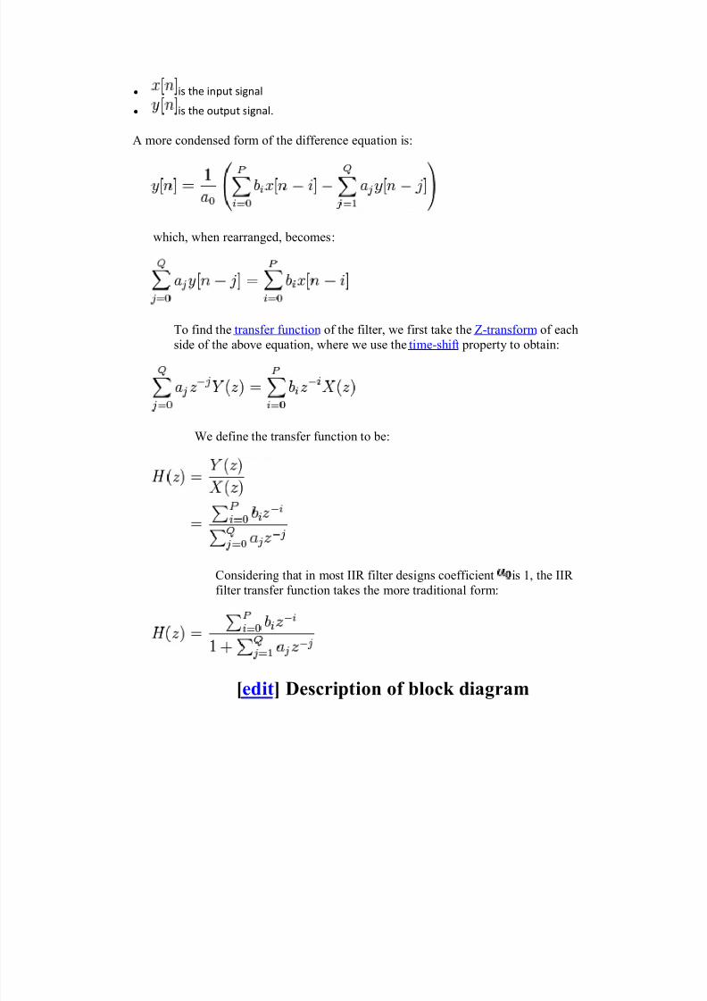
8/6/2019 Notes on Micro Controller and Digital Signal Processing
http://slidepdf.com/reader/full/notes-on-micro-controller-and-digital-signal-processing 67/70
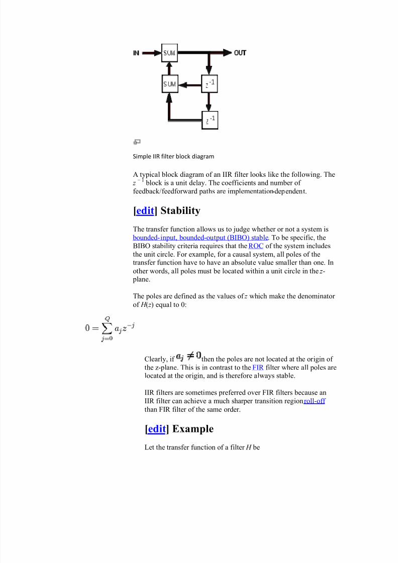
8/6/2019 Notes on Micro Controller and Digital Signal Processing
http://slidepdf.com/reader/full/notes-on-micro-controller-and-digital-signal-processing 68/70
Simple IIR filter block diagram
A typical block diagram of an IIR f ilter looks like the following. The
z í 1
block is a unit delay. The coeff icients and number of
feedback /feedforward paths are implementation-dependent.
[edit] Stability
The transfer function allows us to judge whether or not a system is bounded-input, bounded-out put (BIBO) stable. To be specif ic, the
BIBO stability cr iter ia requires that the R OC of the system includes
the unit circle. For example, for a causal system, all poles of thetransfer function have to have an absolute value smaller than one. In
other words, all poles must be located within a unit circle in the z- plane.
The poles are def ined as the values of z which make the denominator of H ( z) equal to 0:
Clear ly, if then the poles are not located at the or igin of
the z-plane. This is in contrast to the FIR f ilter where all poles arelocated at the or igin, and is therefore always stable.
IIR f ilters are sometimes preferred over FIR f ilters because anIIR f ilter can achieve a much sharper transition regionroll-off
than FIR f ilter of the same order.
[edit] Example
Let the transfer function of a f ilter H be

8/6/2019 Notes on Micro Controller and Digital Signal Processing
http://slidepdf.com/reader/full/notes-on-micro-controller-and-digital-signal-processing 69/70
with ROC a < | z | and 0 < a < 1
which has a pole at a, is stable and causal. The time-domainimpulse response is
h(n) = anu(n)
which is non-zero for n > = 0.
[edit] Applications
The main advantage of IIR f ilters against FIR f ilter is that it uses through recursion less amount of taps. Thereforein digital signal applications the IIR f ilters use less
hardware/sof tware resources than a FIR f ilter. On the
other side IIR f ilters can be instable at processing highfrequency components. Due to instability feature, IIR f ilters require more f ine-tuning than FIR f ilters to achieve
the result of a FIR f ilter.

8/6/2019 Notes on Micro Controller and Digital Signal Processing
http://slidepdf.com/reader/full/notes-on-micro-controller-and-digital-signal-processing 70/70