note to users - welcome to spectrum: concordia … · a simulation tool: omnet++ 117 a.0.1 ... 3.7...
TRANSCRIPT

NOTE TO USERS
This reproduction is the best copy available.
UMI

MULTICHANNEL OPTICAL ACCESS NETWORKS:
DESIGN AND RESOURCE MANAGEMENT
LEHAN MENG
A THESIS
IN
THE DEPARTMENT
OF
COMPUTER SCIENCE AND SOFTWARE ENGINEERING
PRESENTED IN PARTIAL FULFILLMENT OF THE REQUIREMENTS
FOR THE DEGREE OF MASTER OF COMPUTER SCIENCE
CONCORDIA UNIVERSITY
MONTREAL, QUEBEC, CANADA
APRIL 2009
© LEHAN MENG, 2009

1*1 Library and Archives Canada
Published Heritage Branch
395 Wellington Street Ottawa ON K1A0N4 Canada
Bibliotheque et Archives Canada
Direction du Patrimoine de I'edition
395, rue Wellington Ottawa ON K1A 0N4 Canada
Your file Votre r6f6rence ISBN: 978-0-494-63281-9 Our file Notre r&ference ISBN: 978-0-494-63281-9
NOTICE: AVIS:
The author has granted a nonexclusive license allowing Library and Archives Canada to reproduce, publish, archive, preserve, conserve, communicate to the public by telecommunication or on the Internet, loan, distribute and sell theses worldwide, for commercial or noncommercial purposes, in microform, paper, electronic and/or any other formats.
L'auteur a accorde une licence non exclusive permettant a la Bibliotheque et Archives Canada de reproduire, publier, archiver, sauvegarder, conserver, transmettre au public par telecommunication ou par I'lnternet, preter, distribuer et vendre des theses partout dans le monde, a des fins commerciales ou autres, sur support microforme, papier, electronique et/ou autres formats.
The author retains copyright ownership and moral rights in this thesis. Neither the thesis nor substantial extracts from it may be printed or otherwise reproduced without the author's permission.
L'auteur conserve la propriete du droit d'auteur et des droits moraux qui protege cette these. Ni la these ni des extraits substantiels de celle-ci ne doivent etre imprimes ou autrement reproduits sans son autorisation.
In compliance with the Canadian Privacy Act some supporting forms may have been removed from this thesis.
While these forms may be included in the document page count, their removal does not represent any loss of content from the thesis.
Conformement a la loi canadienne sur la protection de la vie privee, quelques formulaires secondaires ont ete enleves de cette these.
Bien que ces formulaires aient inclus dans la pagination, il n'y aura aucun contenu manquant.
1+1
Canada
Abstract
Multichannel Optical Access Networks: Design and Resource
Management
Lehan Meng
At present there is a strong worldwide push towards bringing fiber closer to individ
ual homes and businesses. The next evolutionary step is the cost-effective all-optical
integration of fiber-based access and metro networks. STARGATE [1] is an all-optical
access-metro architecture which does not rely on costly active devices, e.g., Optical Cross-
Connects (OXCs) or Fixed Wavelength Converters (FWCs), and allow low-cost PON tech
nologies to follow low-cost Ethernet technologies from EPON access into metro networks,
resulting in significantly reduced cost and complexity. It makes use of an overlay island
of transparency with optical bypassing capabilities. In this thesis we first propose Optical
Network Unit (ONU) architectures, and discuss several technical challenges, which allow
STARGATE EPONs (SG-EPONs) to evolve in a pay-as-you-grow manner while providing
backward compatibility with legacy infrastructure and protecting previous investment. Sec
ond, and considering all the hardware constraints, we present the corresponding dynamic
bandwidth allocation algorithm for effective resource management in these networks and
investigate their performances (delay, throughput) through simulation experiments.
We further investigate the problem of transmission grant scheduling in multichannel optical
access networks using a scheduling theoretic approach. We show that the problem can be
iii

modeled as an Open Shop and we formulate the joint scheduling and wavelength assign
ment problem as a Mixed Integer Linear Program (MILP) whose objective is to reduce the
length of a scheduling period. Since the problem is known to be NP-hard, we introduce
a Tabu Search based heuristic for solving the joint problem. Different other heuristics are
also considered and their performances are compared with those of Tabu and MILP. Results
indicate that by appropriately scheduling transmission grants and assigning wavelengths,
substantial and consistent improvements may be obtained in the network performance. For
example, Tabu shows a reduction of up to 29% in the schedule length with substantial re
duction in channel idle gaps yielding to both higher channel utilization and lower queuing
delays. Additionally, when the number of channels in the network is not small, the benefits
of performing appropriate wavelength assignment, together with transmission scheduling,
are observed and discussed. We further perform a packet-level simulation on the consid
ered network to study the benefits of efficient grant scheduling; significant improvements
are shown both in terms of system utilization and packet queuing delays.
IV

Acknowledgments
First and foremost I would like to dedicate my gratitude to my parents, without your love,
this dissertation could not have been completed. Thank you for your support during my
education in my early years. Thank you for your continuous encouragement.
I also wish to express my sincere thanks and gratitude to my thesis supervisor and ad
viser, Professor Chadi M. Assi for your expert guidance, help, support and encouragement
throughout my research work. Thank you for introducing me to the concept of research. It
is my proud to have the opportunity to study and work under your supervision.
I also want to express my thanks to my co-supervisor, Prof. Martin Maier, who helped
me greatly since the very beginning when I started to do research. I thank you for your
help, valuable comments and advice on this work.
Great thanks to my colleagues, for their friendship, help and discussions in and out of
this work.
v
Contents
Abstract iii
List of Figures x
List of Tables xii
Abbreviations i
1 Introduction 1
1.1 Traffic Growth 2
1.2 Access Network 4
1.2.1 PONs 4
1.2.2 Multi-channel upgraded PONs (WDM PONs) 8
1.3 Metro-Access Network 10
1.3.1 All Optical Integration 10
1.3.2 LRPONs 12
1.3.3 STARGATE 13
1.4 Thesis Motivation & Contributions 15
vi

1.5 Thesis Organization . 16
2 EPON Overview 18
2.1 EPON Architecture 19
2.2 Devices Options 20
2.3 EPON Operation 23
2.4 Multi-Point Control Protocol (MPCP) 25
2.5 Dynamic Bandwidth Allocation Algorithms (DBAs) 28
2.5.1 Interleaved Polling with Adaptive Cycle Time (IPACT) 28
2.5.2 Grant Sizing and Grant Scheduling 30
3 Multichannel SG-EPON: Architecture and Algorithms 32
3.1 Introduction 32
3.2 STARGATE Architecture 35
3.3 SG-EPON Architecture 40
3.3.1 ONU 41
3.3.2 OLT 45
3.3.3 RSOA & Rayleigh Effect 46
3.4 SG-EPON Operation 50
3.4.1 Provisioning Phase 51
3.4.2 On-Service Phase 51
3.5 DBA in SG-EPON 52
3.5.1 Preliminaries 53
3.5.2 Minimum Bandwidth Guaranteed 56
vii
Bibliography 107
A Simulation Tool: OMNet++ 117
A.0.1 WhyOMNet++ 117
A.0.2 Work with OMNet++ 118
A.0.3 Implementation in OMNet++ 120
IX

3.5.3 Bandwidth Allocation 58
3.5.4 Transmission Scheduling 60
3.6 Simulation Result 63
3.7 Summary 69
4 Transmission Scheduling 70
4.1 Introduction 70
4.2 Related Work 71
4.3 Motivation and Problem Statement 73
4.4 An Efficient Scheduling Policy 76
4.4.1 Preliminaries 76
4.4.2 The Open Shop Problem, OSP 77
4.4.3 Mathematical formulation 79
4.5 A Tabu Search Approach 86
4.5.1 Dispatching Rules 86
4.5.2 Tabu Search Heuristic 88
4.6 Performance Results 93
4.7 Simulation Results 98
4.8 Summary 102
5 Conclusion & Future Work 104
5.1 Conclusion 104
5.2 Future Work 105
viii
List of Figures
1.1 PON Topologies 5
2.2 Downstream Transmission in EPON 23
2.3 Upstream Transmission in EPON 24
2.4 The Scheduling Framework Continuum (N: Number of ONUs, M: Number
of Channels) 31
3.5 STARGATE network architecture 36
3.6 Wavelength routing of an 8 x 8 arrayed waveguide grating 38
3.7 SG-EPON single feeder-fiber network for smooth migration from legacy
TDM ONUs to WDM-enhanced ONUs and long-reach (LR) ONUs 40
3.8 Backreflection lights in a single feeder-fiber WDM/TDM PON using RSOA
based ONUs 46
3.9 Avoidance of impact of backreflections on the upstream transmission from
ONUtoOLT. 47
3.10 Transmission window scheduling: an illustrative example 61
3.11 TDM ONU Traffic Delay (W = 2,D = 1) 64
3.12 TDM ONU Traffic Delay (W = 4,D = 2) 64

3.13 TDM ONU Traffic Delay (W = 4, bidirectional) 65
3.14 WDM ONU Traffic Delay 66
3.15 LR ONU AWG Traffic Delay 67
3.16 non-AWG Traffic Throughput of SG-EPON 68
3.17 AWG Traffic Throughput over Stargate 68
4.18 Illustration of OSP using a Disjunctive Graph 74
4.19 Illustration of OSP using a Disjunctive Graph 75
4.20 Illustration of OSP using a Disjunctive Graph 89
4.21 Modified Disjunctive Graph 90
4.22 Average Utilization on WDM Upstream Channels 99
4.23 Average Utilization on WDM Downstream Channels 100
4.24 Average Utilization on AWG Channels 101
4.25 Average WDM Upstream Traffic Delay 101
4.26 Maximum WDM Upstream Traffic Delay 102
XI

List of Tables
2.1 Fields in a MPCPDU 26
2.2 Grant Scheduling Services 29
3.3 Parameters 63
4.4 Makespan (ms): Experiment Group 1-4 94
4.5 Wasted Bandwidth (%): Experiment Group 1-4 95
4.6 Experiment 98
XII

Abbreviations
ADSL - Asymmetric Digital Subscriber Line
APD - Avalanche Photodiode
APON - ATM Passive Optical Network
ASE - Amplified Spontaneous Emission
ATM - Asynchronous Transfer Mode
AWG - Arrayed Waveguide Grating
BPF - Bandpass Filter
BPON - Broadband Passive Optical Network
CDR - Clock and Data Recovery Circuit
CM - Cable Modem
CO - Central Office
CPM - Critical Path Method
CSMA/CD - Carrier-Sense Multiple Access with Collision Detection
CW - Continuous Wave
CWDM - Coarse Wavelength Division Multiplexing
DBA - Dynamic Bandwidth Allocation
DBR - Distributed Bragg Reflector
DFB - Distributed Feedback
DGM - Disjunctive Graph Model
DSL - Digital Subscriber Line
DWDM - Dense Wavelength Division Multiplexing
EDFA - Erbium-doped Fiber Amplifier
EPON - Ethernet Passive Optical Network
FEC - Forward Error Correction
FTTH/B - Fiber-To-The-Home/Business
FSR - Free Spectral Range
FWC - Fixed Wavelength Converters
1

GPON - Gigabit Passive Optical Network
HDTV - High-Definition Television
IFG - Inter-Frame Gap
IP - Internet Protocol
IPACT - Interleaved Polling with Adaptive Cycle Time
ITU - International Telecommunication Union
LAN - Local Area Network
LAPT - Longest Alternate Processing Time
LD - Laser Diode
LLID - Logical Link Identifier
LPT - Longest Processing Time
LR ONU - Long Reach ONU
LTRPOM - Longest Total Remaining Processing on Other Machine(s)
MAC - Media Access Control
MAN - Metropolitan Area Network
MFL - Multifrequency Laser
MILP - Mixed Integer Linear Program
MPCP - Multi-Point Control Protocol
NASC - Next Available Supported Channel
NP - Nondeterministic Polynomial-time
OBS-M - Optical Burst Switching Multiplexer
OEO - Optical-Electrical-Optical
OFS - Optical Flow Switching
OLT - Optical Line Terminal
ONU - Optical Network Unit
OSP - Open Shop Problem
OXC - Optical Cross-Connect
P2MP - Point-to-Multipoint
P2P - Peer-to-Peer
PIN - Positive-Intrinsic-Negative
PON - Passive Optical Network
PWC - Parametric Wavelength Conversion
QoS - Quality of Service
RF - Radio Frequency
11

RN - Remote Node
ROADM - Reconfigurable Optical Add-Drop Multiplexer
RPR - Resilient Packet Ring
RSOA - Reflective Semiconductor Optical Amplifier
RTT - Round Trip Time
SLA - Service Level Agreement
SP - Service Provider
SPT - Shortest Processing Time
TDM - Time Division Multiplexing
TDMA - Time-Division Multiple Access
TRPT - Total Remaining Processing Time
TW - Transmission Window
VCSEL - Vertical-Cavity Surface-Emitting Laser
VoD - Video on Demand
VOQ - Virtual Output Queue
WAN - Wide Area Network
WDM - Wavelength Division Multiplexing
m
Chapter 1
Introduction
At present, there is a strong worldwide push towards bringing fiber closer to individual
homes and businesses. Fiber-to-the-Home/Business (FTTH/B) or close to it (FTTX) net
works are poised to become the next major success story for optical fiber communica
tions [2]. In fact, FTTH connections are currently experiencing double-digit or even higher
growth rates, e.g., in the United States the annual growth rate was 112% between Septem
ber 2006 to September 2007, and their presence can add value of U.S. $4,000-15,000 to
the selling price of a home [3]. FTTH networks have to unleash their economic poten
tial and societal benefit by opening up the "first/last mile"1 bandwidth bottleneck, thereby
strengthening our information society while avoiding its digital divide. FTTH networks
hold great promise to enable the support of a wide range of new and emerging services and
applications, such as triple play, video on demand (VoD), videoconferencing, peer-to-peer
(P2P) audio/video file sharing, multichannel high-definition television (HDTV), multime
dia/multiparty online gaming, telemedicine, telecommuting, and surveillance [4].
1 First Mile(also called "last mile"): Mile or Km that connects the service provider central offices to businesses and residential subscribers.
1

1.1 Traffic Growth
Over the past decade, the telecommunications infrastructure has transitioned from a copper
based plant to a fiber based plant. This transition started with the Wide Area Network
(WAN) and then progressed to the Metropolitan Area Network (MAN), which provides
connectivity between cites (WAN) or between service providers within a metropolitan area
(MAN). Meanwhile, in Local Area Networks (LANs), which interconnect nodes within
an individual location, the bit rates have also experienced tremendous migration from 10
Mbps to lGbps.
Concurrently, accompanied by the huge improvement in network speed, data traffic is
increasing at an unprecedented rate as well. Sustainable data traffic growth rate of over
100% per year has been observed since 1990. There were periods when a combination
of economic and technological factors resulted in even greater growth rates, e.g., 1000%
increase per year in 1995 and 1996 [5]. As we can expect in the future, more users are
getting online and those who are already online are spending more time online, using more
bandwidth-intensive applications. Besides, more services and new applications will be
come available as bandwidth per user increases.
However, in the access network, which provides the link between the private and public
networks, little has been changed. It still relies on an aging copper infrastructure. The most
widely deployed "broadband" solutions today are Digital Subscriber Line (DSL) and cable
modem (CM) networks. Although, these techniques overwhelmed 56 Kbps dial-up lines,
they can not keep up with today's increasing bandwidth demand. Further, they are built
2

on top of existing communication infrastructure to carry voice and analog signals, respec
tively; hence their retrofitted versions to carry data are not optimal. Currently deployed
blends of asymmetric DSL (ADSL) technologies provide 1.5 Mbits/s of downstream band
width and 128 Kbits/s of upstream bandwidth at best. Moreover, the distance of any DSL
subscriber to a Central Office (CO) must be less than 18000 ft because of signal distortions.
Although variations of DSL such as very-high-bit-rate DSL (VDSL), which can support up
to 50 Mbits/s of downstream bandwidth, are gradually emerging, these technologies have
much more severe distance limitations. For example, the maximum distance over which
VDSL can be supported is limited to 1500 ft. CATV networks provide Internet services
by dedicating some radio frequency (RF) channels in a coaxial cable for data. However,
CATV networks are mainly built for delivering broadcast services, so they do not fit well
for the bidirectional communication model of a data network. At high load, the network
performance is usually frustrating to end users.
Therefore, the first mile, still remains a major bottleneck between high-capacity LANs
and the subscriber home network. The huge amount of bandwidth that the backbone carries,
has to reach the users premises through the access network. To alleviate these bandwidth
bottlenecks, optical fibers are penetrating deeper into the first mile with a great promise to
offer FTTH and FTTB. Consequently, most companies (e.g., NT&T, Verizon) are switching
to fiber technology [6]. This, as a result, raises the need for inexpensive, simple and scalable
technology, capable of delivering bundled "triple-play" to end-users (i.e., voice, data and
video).
3
1.2 Access Network
As mentioned, a fiber infrastructure is required in the access network to provide higher
bit rates as well as better scalability. Besides, from the perspective of service provider,
unlike in WANs and MANs where links carry the bit streams of many revenue generating
customers, links in access networks carry a single or just a few revenue generating bit
streams [7]. For this reason, the access network is very sensitive to cost as well.
1.2.1 PONs
A Passive Optical Network (PON) between a service provider and customer premises can
provide a low-cost environment that leads high bandwidth in WAN or MAN directly to the
end-users.
PON is an optical network in which a shared fiber medium is created using a passive op
tical splitter/combiner in the physical plant. It brings the following benefits: (1) allows long
distance connections between COs and customer premises, operating at distances over 20
km, (2) minimizes the amount of optical transceivers, CO terminations, and fiber deploy
ment, (3) is capable of supporting gigabit per second (Gbps) speeds, (4) keeps the cost as
low as DSL and cable networks by making use of shared fiber medium and passive compo
nents in the physical plant, which also ensures low maintaining complexity as well as low
(or without) power cost at remote facilities, (5) allows for video broadcasting as either IP
video or analog video using a separate wavelength overlay [8], (6) is optically scalable to
be upgraded to higher bit rates (i.e., GPON) or additional wavelengths (i.e., WDM PON).
Because of all the above features, PONs exhibit their potential advantages to open up the
4
0NU4 0NU5
(a) Tree topology
' 0NU1 / 0NU2
0NU5 0NU3
(b) Bus topology
0NU4
0NU5 (c) Ring topology
0NU4 0NU5
(d) Tree with redundant trunk
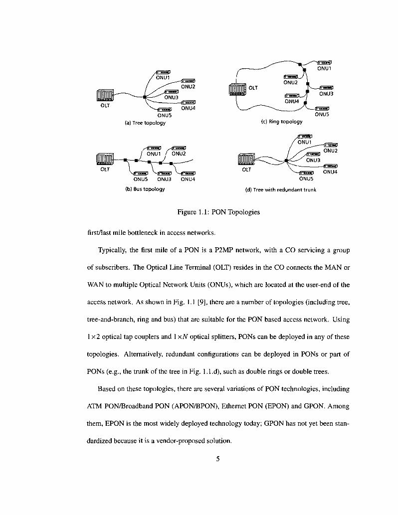
Figure 1.1: PON Topologies
first/last mile bottleneck in access networks.
Typically, the first mile of a PON is a P2MP network, with a CO servicing a group
of subscribers. The Optical Line Terminal (OUT) resides in the CO connects the MAN or
WAN to multiple Optical Network Units (ONUs), which are located at the user-end of the
access network. As shown in Fig. 1.1 [9], there are a number of topologies (including tree,
tree-and-branch, ring and bus) that are suitable for the PON based access network. Using
1x2 optical tap couplers and 1 xN optical splitters, PONs can be deployed in any of these
topologies. Alternatively, redundant configurations can be deployed in PONs or part of
PONs (e.g., the trunk of the tree in Fig. 1.1.d), such as double rings or double trees.
Based on these topologies, there are several variations of PON technologies, including
ATM PON/Broadband PON (APON/BPON), Ethernet PON (EPON) and GPON. Among
them, EPON is the most widely deployed technology today; GPON has not yet been stan
dardized because it is a vendor-proposed solution.
5
APON/BPON
The BPON standard [10] was introduced first; in 1999, it was accepted by the International
Telecommunication Union (ITU). The standard was endorsed by a number of network
providers and equipment vendors which cooperated together in the Full Service Network
Access (FSAN) group2. The FSAN group proposed that the ATM protocol should be used
to carry user data, hence sometimes this type of PONs are also referred to as APONs [11].
One advantage of APON is that queues in the OLTs and ONUs can implement various
Quality of Service (QoS) policies to guarantee better support for real-time traffic such as
voice and video. Besides, the small size of ATM cells and the use of virtual channels
and links allow the allocation of available bandwidth to end users with a fine granularity.
However, in APON, data sent between the switch and customer that has the form of Internet
Protocol (IP) packets needs to be converted to ATM cell format. This requires additional
complexity at the receiving and sending side. If a cell gets corrupted or invalidated, an
entire datagram will be invalidated and it will travel throughout the entire network, using
network resources unnecessarily. For any packet size distribution in the network, in order to
transmit the same amount of information as Ethernet, BPON requires about 10% more data
because of extra ATM overhead. Furthermore, considering the fact that ATM switches and
cards are more expensive than Ethernet components [12], and that the much simpler, data
only oriented Ethernet protocol found a widespread use in local area networks and started
to replace ATM in many metropolitan area and backbone networks, ATM based BPON did
not gain much popularity.
2http://www.fsanweb.org
6

EPON
In November 2000, a group of Ethernet vendors (e.g., PMC-Sierra Inc. and Dasan Net
works) kicked off their own standardization effort to develop Ethernet Optical Network
(EPON) under IEEE 802.3. Data packets in EPON are transmitted in variable-length of up
to 1,518 bytes according to the IEEE 802.3 protocol for Ethernet, instead of fixed-length
53-byte cells in APON, as specified by the ATM protocol. EPON vendors and network op
erators are focusing initially on developing a solution for delivering data, video, and voice
over a single platform. While EPON offers higher bandwidth together with broader service
capabilities than APON, it costs less, and the architecture is broadly similar and adheres to
many ITU-G.983 recommendations.
GPON
Since the bit rate of BPON and EPON does not exceed 622 Mbps and 1.2 Gbps, the FSAN
group specifies a PON system operating at bit rates more than 1.2 Gbps - GPON. The
proposed protocol for this speed of data is the Generic Framing Procedure which allows
a mix of variable-size frames and ATM cells [13]. GPON delivers twice the bandwidth
of EPON at its full speed of 2.5 Gbps. Meanwhile, GPON-capable transceivers provide an
adequate loss budget to enable higher split ratios up to 1:64 splits, which doubles the ratio of
up to 1:32 in BPON and EPON; they can provide the ability to achieve the necessary optical
loop length distances as well. Therefore, the attributes of GPON make it a logical choice
for all-FTTx deployments. Like EPON, GPON has Ethernet as the Layer 2 technology, but
it goes much further. However, the deployment of GPON requires an upgrade in all the
7

optical units of PON. For example, each ONU will be altered to enable transmission on a
higher rate channel. In that context, EPON is currently considered the most cost-effective
solution for the bottleneck access.
1.2.2 Multi-channel upgraded PONs (WDM PONs)
Although single channel PON provides higher bandwidth than traditional copper-based
access networks, there exists a need for further increasing the bandwidth of the PON by
employing wavelength-division multiplexing (WDM). The reason is that more and more
newly emerged bandwidth consuming applications and services are carried in the network,
such as high definition TV (HDTV), digital cinema, videoconferencing, peer-to-peer file
sharing, etc. As a result, multiple wavelengths may be supported in either or both upstream
and downstream directions in PON. Such a PON is known as a WDM-PON. Architectures
for WDM-PONs have been proposed as early as the mid-1990s [14]. In [14] the authors
proposed a WDM PON, called RITE-NET, that utilizes a wavelength router to route indi
vidual wavelengths to ONUs. More recent studies on WDM based multi-channel PONs
can also be found in many literature, such as Stanford University access (SUCCESS) ar
chitecture in [15], SUCCESS-DWA architecture in [16], and a hybrid WDM/TDM PON
architecture in [17].
The WDM technique has proved to be an excellent solution for the bandwidth thirsty
end-users, and for the expansion of the capacity of existing TDM PON networks without
the need to change the network infrastructure substantially. While upgrading from TDM
to WDM, two major wavelength spacing options are available. A wavelength spacing of
8
20 nm deployed between downstream and upstream transmission is called Coarse WDM
(CWDM). The ITU G.695 defines the laser grid for CWDM with a wavelength range from
1271 nm to 1611 nm. A shortcoming of CWDM is that the total number of channels is
limited to 18. As a result, the CWDM-PON lacks in scalability, especially when a normal
single-mode fiber with water-peak attenuation range is used [18]. Also, shorter wavelength
channels experience higher loss, thereby limiting the transmission distance or splitting ra
tio.
Dense WDM (DWDM) has wavelength spacing that is far lesser than that of CWDM,
which is less than 3.2 nm. This is because DWDM is designed to support more wave
lengths in a limited spectrum region where an erbium-doped fiber amplifier (EDFA) can
be used. Due to its capability of providing enough bandwidth to many subscribers, the
DWDM-PON is regarded as the ultimate PON system. ITU G.692 defines a laser grid for
point-to-point WDM systems based on 100 GHz wavelength spacing with a center wave
length of 193.1 THz(1553.52 nm) over the frequency region of 196.1 THz(1528.77 nm) to
191.7 THz(1563.86 nm). This 100 GHz spacing has been applied to many DWDM sys
tems. However, 50 GHz spaced laser diodes (LDs) and filters are commercially available
today, and they can be used to increase the number of channels. Wavelengths that reach up
to 1600 nm also have been used to further exploit the cyclic feature of the Arrayed Waveg
uide Grating (AWG). The AWG can be located at a remote node for demultiplexing and
multiplexing in either or both transmission directions, upstream and downstream. In such a
multichannel system, crosstalk between adjacent channels should be avoided, by carefully
selecting among optical sources with different configurations as well as the center wave
length of the WDM filter. Therefore, the DWDM PON costs more than the CWDM PON
9

due to, for example, the need of tunable devices and temperature control.
1.3 Metro-Access Network
1.3.1 All Optical Integration
After paving in FTTH/B networks all the way to the end user with optical fiber, the next
evolutionary step is the all-optical integration of fiber-based access and metro networks
with the objective to avoid costly Optical-Electrical-Optical (OEO) conversion at interme
diate nodes (e.g., OLT) and thereby achieve major cost savings [19]. Very recently, re
search on optically integrated access-metro network architectures and protocols has gained
momentum.
NGI ONRAMP
One of the first research projects on the all-optical integration of access and metro edge ring
networks was the so-called Next Generation Internet Optical Network for Regional Access
using Multiwavelength Protocols (NGI ONRAMP) testbed [20,21]. The ONRAMP net
work architecture consists of a bidirectional feeder WDM ring network which connects
multiple access nodes with one another and with the backbone network. The ONRAMP
testbed implements and demonstrates apart from optical flow switching (OFS) other fea
tures such as protection, medium access control (MAC) protocols, control, and manage
ment.
10
SUCCESS
Another interesting research project is the Stanford University access (SUCCESS) net
work [15]. Its design objective is to provide a smooth migration path from currently widely
deployed time division multiplexing (TDM) PONs to future WDM PONs and their all-
optical integration by means of an optical single-fiber collector feeder ring, while guar
anteeing backward compatibility with existing TDM PON customer premises equipment
(CPE) and providing increased capacity to users on new WDM PONs.
MARIN
The so-called Metro Access Ring Integrated Network (MARIN) optically integrates hybrid
TDM/WDM PONs into interconnected metro access ring networks by using optical recon-
figurable and parametric wavelength conversion (PWC) devices [22]. In MARIN, metro
access ring networks can dynamically share and leverage light sources that were originally
used to serve only the attached access network, resulting in a more efficient utilization of
network resources and improved network performance [23].
An OBS based WDM/TDM Hybrid PON
A new all-optical access-metro network based on optical burst switching (OBS) was re
cently proposed and investigated in [24]. The optical access network segment consists of
a hybrid WDM/TDM PON with reflective ONUs, a frequency-cyclic AWG at the remote
node used as wavelength (de)multiplexer, and a tunable laser and tunable photodetector
stack at the OLT. Multiple WDM/TDM PONs are transparently interconnected by using
a so-called optical burst switching multiplexer (OBS-M) which optically interfaces with a
11
distant metro router. The OBS-M deploys an optical cross-connect (OXC) that interfaces
with the attached WDM/TDM PONs and a number of fixed wavelength converters (FWCs).
The OBS-M deploys a stack of tunable laser diodes to send optical continuous wave (CW)
signals to the attached reflective ONUs, each equipped with a reflective semiconductor op
tical amplifier (RSOA), for remote modulation of upstream data. The basic architecture
of a single OBS-M and distant router can be extended to ail-optically interconnect mul
tiple OBS-Ms with a distant router through a reconfigurable optical add-drop multiplexer
(ROADM) based metro network with either a tree or a ring topology. According to [24],
the all-optical OBS based access-metro network is strictly nonblocking in the wavelength,
time, and space domains. At the downside, however, the OLT and OBS-M architectures
with the required tunable laser stacks, tunable photodetector stacks, wavelength converter
banks, and OXC significantly add to the cost, power consumption, footprint, and complex
ity of the all-optical access-metro network nodes.
1.3.2 LRPONs
A range of PONs, so-called SuperPON, further extends the coverage span of a TDM/WDM
PON from 20 km to 100 km or even larger, by making use of WDM technology together
with Optical Amplifiers [25-29]. These SuperPONs are also referred to as Long-Reach
Passive Optical Network (LR-PON) in [30]. The study of LR PONs is mainly motivated
by the facts that: 1) an increasing number of advanced components have been deployed
for the broadband access network, e.g., optical amplifiers which greatly extend the span
of the optical access networks; 2) the mature WDM technology enables more wavelengths
12

to be multiplexed on a fiber, with each wavelength operating (soon) at a transmission rate
of 40-100 Gbps [30]. By developing and deploying such LR PONs in access network, the
network will be simplified by means of less equipment interfaces, network elements, and
even nodes. The OLT of a traditional PON can be replaced at the local exchange by some
low-power physical-layer equipments, such as optical amplifiers. Higher-layer networking
functions can then be located further upstream in the "network cloud". As a result, fewer
COs may be required in the metro network, thereby reducing capital expenditure (CapEx)
as well as their maintenance cost, namely operational expenditure (OpEx). Due to the
larger cover range, e.g., 100 km, the optical access and metro network are combined into
an integrated system, where the architecture is converged and the overhead at the interface
between access and metro could be reduced significantly.
1.3.3 STARGATE
Authors of [1] proposed a novel metro-access network - STARGATE, which is an evo
lutionary upgrade of WDM EPONs and Resilient Packet Ring (RPR) in a cost-effective
manner. It also ail-optically integrates the access network with Ethernet-based MAN to
provide transparent connection at the wavelength and sub-wavelength granularity on de
mand between ONUs residing in different WDM EPONs. In STARGATE, the following
three tasks are addressed [6]:
1) Cost reduction: As mentioned, cost is key in access networks due to the small num
ber of cost-sharing subscribers compared to metro and wide area networks. Devices and
components that can be mass produced and widely applied to different types of equipment
13

and situations must be developed. It is important that installation costs, which largely con
tribute to overall costs, be reduced. A promising example for cutting installation costs is
NTT's envisioned do-it-yourself (DIY) installation deploying a user-friendly hole-assisted
fiber that exhibits negligible loss increase and sufficient reliability, even when it is bent at
right angles, clinched, or knotted, and can be produced economically.
2) Colorless ONU: The next target is to make the ONU, which connects one or more
subscribers to the PON, colorless (i.e., wavelength-independent). Colorless ONUs require
either no light source at all or only a broadband light source, resulting in decreased costs,
simplified maintenance, and reduced stock inventory issues.
3) WDM PONs: The third and final target is to increase the number of wavelength
channels by means of wavelength-division multiplexing (WDM). The use of WDM tech
nologies allows access network operators to respond to user requests for service upgrades
and network evolution. Deploying WDM adds a new dimension to TDM PONs. The ben
efits of the new wavelength dimension are manifold. Among others, it may be exploited:
• To increase network capacity
• To improve network scalability by accommodating more end users
• To separate services
• To separate service providers
More details about STARGATE, such as the architecture of STARGATE, the architec
ture of EPON that attached to STARGATE (SG-EPON), and the structure of ONU/OLT
will be introduced in Chapter 3.
14

1.4 Thesis Motivation & Contributions
In this thesis, we take a different approach to ail-optically integrate access and metro net
works. Instead of deploying costly active devices, e.g., OXC or FWCs, we rather rely on
low-cost passive yet powerful optical devices. The all-optical access-metro architecture un
der consideration, known as STARGATE, lets low-cost PON technologies follow low-cost
Ethernet technologies from EPON access networks into metro networks, resulting in sig
nificantly reduced costs and complexity. It makes use of an overlay island of transparency
with optical bypassing capability of OLTs.
In this thesis we first propose ONU architectures, and discuss several technical chal
lenges, which allow STARGATE EPONs (SG-EPONs) to evolve in a pay-as-you-grow
manner while providing backward compatibility with legacy infrastructure and protecting
previous investment. SG-EPON is hence a cost-effective multichannel access network ar
chitecture which will be used for our study throughout the thesis. Second, and considering
all the hardware constraints, we present the corresponding dynamic bandwidth allocation
algorithm for effective resource management in these networks and investigate their per
formances (delay, throughput) through simulation experiments.
We further investigate the problem of transmission grant scheduling in multichannel
optical access networks using a scheduling theoretic approach. We show that the problem
can be modeled as an Open Shop and we formulate the joint scheduling and wavelength as
signment problem as a Mixed Integer Linear Program (MILP) whose objective is to reduce
the length of a scheduling period. Since the problem is shown to be NP-hard, we introduce
a Tabu Search based heuristic for solving the joint problem. Different other heuristics are
15
also considered and their performances are compared with those of Tabu and MILP. Results
indicate that by appropriately scheduling transmission grants and assigning wavelengths,
substantial and consistent improvements may be obtained in the network performance. For
example, Tabu shows a reduction of up to 29% in the schedule length with substantial re
duction in channel idle gaps yielding to both higher channel utilization and lower queuing
delays. Additionally, when the number of channels in the network is not small, the benefits
of performing appropriate wavelength assignment, together with transmission scheduling,
are observed and discussed. We further perform a packet-level simulation on the consid
ered network to study the benefits of efficient grant scheduling; significant improvements
are shown both in terms of system utilization and packet queuing delays.
1.5 Thesis Organization
This thesis is organized as follows. In Chapter 2, we present an overview of the EPON
technology, as well as some related work. In Chapter 3, we first outline the state-of-the-
art STARGATE architecture, and elaborate on the various proposed ONU structures for
SG-EPONs. We also outline the operation of SG-EPONs and describe our proposed DBA
algorithm in great details. In Chapter 4, we investigate the problem of transmission grant
scheduling in multichannel optical access networks using a scheduling theoretic approach.
We show that this problem can be modeled using an Open Shop model and we formulate
the joint scheduling and wavelength assignment problem as a Mixed Integer Linear Pro
gram (MILP) whose objective is to reduce the length of a scheduling period. Significant
performance improvement is observed through our simulation results. Finally, we conclude
16

this thesis in Chapter 5.
17
Chapter 2
EPON Overview
Ethernet PON (EPON) is a PON-based network that carries data traffic encapsulated in
Ethernet frames as defined in the IEEE 802.3 standard [31]. 8B/10B line coding1 is used
and it operates at standard Ethernet speed. Ethernet PON gains much more popularity than
other technologies due to the following facts:
• Efficiency: 95% of LANs use Ethernet; EPONs and their WDM upgraded descen
dants are likely to become the standard due to their capability of natively carrying variable-
size IP packets in a simpler and more efficient way than their ATM-based counterparts
(APON) [1]. It becomes clear that ATM PON may not be the best choice to interconnect
two Ethernet networks. For example, if an ATM cell is corrupted or dropped, the entire IP
datagram is invalidated. However, the remaining cells carrying other portions of the same
IP datagram will propagate much further in the network, therefore the network resources
are consumed unnecessarily. In addition, some overhead (e.g., ATM adaptation layer 5
(AAL-5)) is required to be added to each IP datagram before it enters the ATM network.
18 user bits encoded as 10 line bits
18
It is shown that, with the tri-modal packet-size distribution reported in [32], there is ap
proximately 13% more bytes sent in APONs than in Ethernet networks to deliver the same
amount of data.
• Cost: From the perspective of cost-effectiveness, ATM is a more expensive technol
ogy than Ethernet, e.g., ATM switches and network cards cost significantly (roughly 8x)
more than Ethernet switches and network cards [33].
• Speed: High-speed Gigabit Ethernet deployment is widely accelerating and 10 Giga
bit Ethernet products are becoming available. Ethernet technology seems to be the logical
choice for an IP data-optimized access network. The quality-of-service techniques can also
be well adopted in EPON, supporting voice, data and video traffic.
To sum up, Ethernet, which is easy to scale and manage, is winning new grounds in
MAN and WAN.
2.1 EPON Architecture
In principle, EPONs may have any topology suitable for access networks. Typically,
EPONs have a physical tree topology with the central office (CO) located at the root and
the subscribers connected to the leaf nodes of the tree, as illustrated in Fig. 1.1 (a). Each
EPON can be viewed as a P2MP network, with passive components (such as optical split
ters and optical fibers) in the signal's path from source to its destination. According to
the standard IEEE 802.3ah, an EPON comprises one OLT and multiple ONUs. An OLT
resides in the CO and interconnects access network to MAN or WAN. It connects to mul
tiple ONUs through a 1:N passive optical splitter/combiner (coupler). One of the most
19

important responsibility of OLT is to allocate bandwidth to ONUs in EPON, according
to their individual demands. Traffic from OLT to an ONU is called "downstream" traf
fic (point-to-multipoint), and traffic in the opposite direction is called "upstream" traffic
(multipoint-to-point) [34].
The ONUs are deployed at subscribers' premises and provide bandwidth either to the
home in terms of FTTH, or alternatively to the business/curb, resulting in a FTTB/FTTC
structure. Each ONU connects several users to the OLT, buffering data received from these
attached users. To support differentiated services an ONU may use priority queues, one for
each traffic class.
2.2 Devices Options
The selection of optical components (e.g, transmitters, receivers, (de)multiplexers, etc.) at
OLT/ONU may differ significantly based on the choice of appropriate wavelengths and
their spacing [18].
Transmitter Options
Optical sources can be classified into several groups, on the basis of the wavelength genera
tion pattern. They are (1) a wavelength-specified source, (2) a multi-wavelength source, (3)
a wavelength-selection-free source, and (4) a shared source. Note that the multi-wavelength
source is applicable only to the OLT and the shared source is applicable only to ONU. For
the other two types, they can be applied to both [18].
Wavelength-Specified Source: This optical source emits a fixed wavelength from each
20
component. In order to tune the source to the required wavelength, a wavelength monitor
ing circuit and a controller for each component are normally needed. A common dis
tributed feedback (DFB)/distributed Bragg reflector (DBR) laser diode, a vertical-cavity
surface-emitting laser (VCSEL) diode, and a tunable-laser diode can be categorized into
this group. However, this type of transmitter may not be suitable to be deployed at OLTs,
because it requires an array of these optical sources, and each of them is set to its individual
wavelength.
Multi-wavelength Source: A component belonging to this category is capable of gen
erating multiple wavelengths at the same time, and thus is useful for the OLT. Several WDM
channels, integrated in a compact device, can be tuned simultaneously. Multifrequency
Laser (MFL), Gain-Coupled DFB LD Array and Chirped-Pulse WDM can be categorized
into this group.
Wavelength-Selection-Free Source: For this type of source, the wavelength is decided
externally by the factors such as a filter or injection signal. Due to the temperature change,
aging effect, or circuit malfunction, the source wavelength will sometimes drift from its
original phase. A wavelength-selection-free source can help such sources to operate free
from the wavelength-tuning problem, for the reason that the wavelengths are determined
less by the environmentally sensitive external factors such as optical filters or injected sig
nals [18].
Shared Source (or Loop-Back Source): Much research work has been done to elimi
nate optical sources at the ONU, because it is risky and costly to let each ONU manage its
transmission wavelength. Any ONU deviated from its assigned channel will degrade both
of its own and its adjacent channels. As a solution, optical sources can only be provided
21
at OLT. ONUs with sources in this group only modulate the unmodulated optical signal
from OLT and then send it back. In some scenario, the same wavelength can even be used
in both upstream and downstream directions, leading to the so-called shared-source solu
tion. The bidirectional transmission on the same wavelength is achieved by using only a
portion of the unmodulated signal for downstream data, leaving the remaining portion for
an ONU to modulate its upstream data. Two types of modulator - external modulator and
semiconductor optical amplifier (SOA) - have been used for this purpose.
Receiver Options
A receiver module consists of a photodetector (PD) and the accompanying electronics parts
for signal recovery. Positive-intrinsic-negative (PIN) and avalanche photodiode (APD) are
commonly used PDs, which find different applications according to the required sensitiv
ity. Electronic parts, usually composed of preamplifier, main amplifier, and clock and data
recovery circuits (CDRs), depend on the protocol used on each wavelength. Since each
wavelength can work separately in a WDM PON, each receiver can be configured individ
ually.
Remote Node Options
Normally, either a splitter or a passive wavelength router can be used at remote node (RN).
A splitter distributes all incoming signals evenly onto all output ports. This option requires
a wavelength filter at each ONU. The specifications of the splitter can be found in Telcordia
GR 1209 [35] or GR 1221 [36]. Actually, a splitter introduces more signal loss than a
wavelength router.
22

Figure 2.2: Downstream Transmission in EPON
The AWG has been a successful device in WDM industry. It is widely used in long
distance WDM systems as a multiplexer/demultiplexer and as an add-drop multiplexer
(ADM). More details about AWG will be introduced in Chapter 3.
2.3 EPON Operation
According to the IEEE 802.3 standard, an Ethernet network can be deployed with either
of the following configurations: over a shared medium using the Carrier-Sense Multiple
Access with Collision Detection (CSMA/CD) protocol, or using a switch with full-duplex
P2P links to each network node. However, properties of EPON shows that it does not
belong to any of the two options, or rather, it is a mixing of both.
The legacy TDM EPON operates on two wavelengths: typically 1310 nm for the up
stream transmission and 1550 nm for the downstream transmission. In the downstream
direction, as shown in Fig. 2.2 [37], OLT broadcasts data packets to each ONU through
23
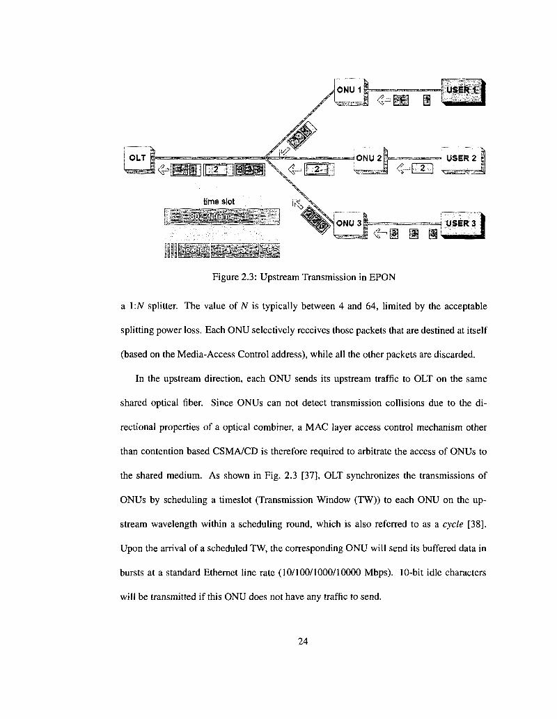
Figure 2.3: Upstream Transmission in EPON
a l:N splitter. The value of N is typically between 4 and 64, limited by the acceptable
splitting power loss. Each ONU selectively receives those packets that are destined at itself
(based on the Media-Access Control address), while all the other packets are discarded.
In the upstream direction, each ONU sends its upstream traffic to OCT on the same
shared optical fiber. Since ONUs can not detect transmission collisions due to the di
rectional properties of a optical combiner, a MAC layer access control mechanism other
than contention based CSMA/CD is therefore required to arbitrate the access of ONUs to
the shared medium. As shown in Fig. 2.3 [37], OLT synchronizes the transmissions of
ONUs by scheduling a timeslot (Transmission Window (TW)) to each ONU on the up
stream wavelength within a scheduling round, which is also referred to as a cycle [38].
Upon the arrival of a scheduled TW, the corresponding ONU will send its buffered data in
bursts at a standard Ethernet line rate (10/100/1000/10000 Mbps). 10-bit idle characters
will be transmitted if this ONU does not have any traffic to send.
24
As a result, the performance of an EPON depends on the efficiency of its timeslot
allocation scheme, which is also referred to as bandwidth allocation scheme. Typically,
bandwidth allocation can be performed either in a static manner (fixed time-division multi
ple access (TDMA)) or dynamically (Dynamic bandwidth allocation (DBA)) according to
the instantaneous variation of bandwidth demand of each ONU.
2.4 Multi-Point Control Protocol (MPCP)
At the MAC control layer, MPCP is the protocol used by an OLT to arbitrate transmis
sions of ONUs on the shared upstream wavelength(s). It is developed by the IEEE 802.3ah
Task Force [39]. Note that MPCP is not concerned with a particular bandwidth alloca
tion scheme; rather it is a framework which will facilitate the implementation of various
bandwidth allocation algorithms in EPON. Five MPCP frames {GATE, REPORT, REGIS
TER .REQUEST, REGISTER, REGISTERJiCK) are defined to exchange control informa
tion between OLT and ONUs. Commonly these five MPCP frames are also referred as
MPCP data units (MPCPDUs), which are all 64 bytes MAC control frames consisting of
the fields as shown in Table. 2.1.
In addition, two operation modes (namely, auto-discovery/registration and normal op
eration) are also defined in MPCP. Recall that MPCP does not allow an ONU to trans
mit any data unless it is granted by the OLT. Thus, after boot-up, an disconnected ONU
would silently wait for a grant from the OLT. Auto-discovery, which employs four MPCP
messages (GATE, REGISTER_REQ, REGISTER and REGISTER^CK) [37], is used to
detect such ONU and to learn its round-trip delays as well as its MAC address. Some other
25

Table 2.1: Fields in a MPCPDU Fields Destination address (DA)
Source address (SA)
Length/type
Opcode
Timestamp
Pocode-specific fields/pad
Frame check sequence (FCS)
Octets 6
6
2
2
4
40
4
Description 48bits address of the station(s) for which the frame is intended. 48bits individual address of the station sending the frame. With value 88-08, universally assigned to identify MAC control frames. This field identifies a specific MAC control frame by different values This field carries the value of MPCP clock corresponding to the transmission of the first byte of the DA. These fields carry information pertinent to specific MPCP functions. This field carries a CRC-32 value used by the MAC to verify integrity of received frames.
mechanisms is also required to ensure the success of MPCP framework, such as RTT mea
surement and collision avoid, however, the discover phase itself is not a very complicated
process. Therefore, our study in this thesis will only focus on the other mode - normal
operation.
In the normal (on-service) operation, the protocol relies on two Ethernet messages
(GATE and REPORT) to enable the request- grant mechanism between OLT and ONUs.
The GATE message is sent from the OLT to an ONU to inform its transmission starting
time (Tstart) and the length of the TW (Tiength). Since a MPCP message is stamped with the
local time (at the OLT and each ONU) while passing the MAC layer, at an ONU, this time
stamp from OLT can be used for two purposes. First, this ONU will synchronize its local
time in case of any potential clock drift, so that it keeps synchronized with the OLT. More
over, it will also program its local registers with Tstart and Tiength that are obtained from the
received GATE message. Once the upstream transmission timer is due, this ONU will start
26

transmitting. While transmitting, it needs to be guaranteed that no Ethernet frames is frag
mented. That is, if the next frame in the queue does not fit the remainder of the assigned
timeslot (or TW), it will be deferred to the next cycle (or scheduling round), leaving some
unused portion in the current TW.
On the other hand, a REPORT message is sent from an ONU to the OLT, to convey the
local conditions (such as buffer occupancy) of this ONU. The OLT will use this information
to make decisions of bandwidth allocation. REPORT messages are sent in the assigned
TWs of ONUs with their data frames. Typically, the REPORT message contains the desired
size of next TW according to the associated ONU's buffer occupancy. Note that while
requesting a timeslot, each individual ONU should also account for the additional overhead
other than the size of buffered data, for example, the 64-bit frame preamble and 96-bit inter-
frame gap (IFG) with each Ethernet packet.
When the OLT receives a timestamped REPORT, the next bandwidth allocation deci
sion is made according to the reported bandwidth requirement. In addition, the OLT will
also recalculate the RTT time to the reporting ONU. For a specific description of calcula
tion of RTT, the interested reader is referred to [37]. After the DBA process completes,
the OLT will write the schedule in GATE message(s) and then broadcasts these GATE(s)
on downstream wavelength to inform each reporting ONU of the Tstart and Tiength of its
next scheduled TW. Again, MPCP framework does not specify any particular DBA algo
rithm. Therefore, the schedule decision as well as the resulting network performance varies
greatly as different DBA algorithms are deployed in EPON. In Chapter 4, we present an
efficient transmission scheduling algorithm that greatly improves the performance of our
SG-EPON over some simple scheduling schemes.
27
2.5 Dynamic Bandwidth Allocation Algorithms (DBAs)
A dynamic bandwidth allocation scheme deployed at OLT is responsible for computing
the granted TW size for each ONU according to their individual reported requirement.
The granted size in a GATE message is not fixed but varies from a cycle to another as
the bandwidth demand (or queue occupancy) of the associated ONU changes. Therefore,
unlike a static allocation scheme, DBA enables the statistical multiplexing among ONUs
in an EPON. It reduces the assigned timeslot when there is less or no upstream data at an
ONU, thereby allowing the excess bandwidth to be used by other ONUs with high upstream
traffic load.
2.5.1 Interleaved Polling with Adaptive Cycle Time (IPACT)
One of the dynamic scheduling algorithms, so-called IPACT, is proposed in [38]. In this
algorithm, the same two messages, GATE and REPORT, are used to enable control-level
communication between OLT and ONUs. With IPACT, the OLT will poll each ONU in the
same cycle for their bandwidth demand. Upon receiving the REPORT(s), this OLT will
generates schedule decisions and then sends GATE message(s) to each reporting ONU to
gether with another polling message for the next cycle. Therefore, multiple polling requests
are overlapped in time. More details about IPACT can be found in [38].
It is worth mentioning that, in [38], a few approaches (services) are also presented to
specify how an OLT can make bandwidth allocation decisions according to the received
demands. It is shown in Table 2.22 [38]. 2A: The allocated window size to an ONU. R: The requested window size of an ONU
28
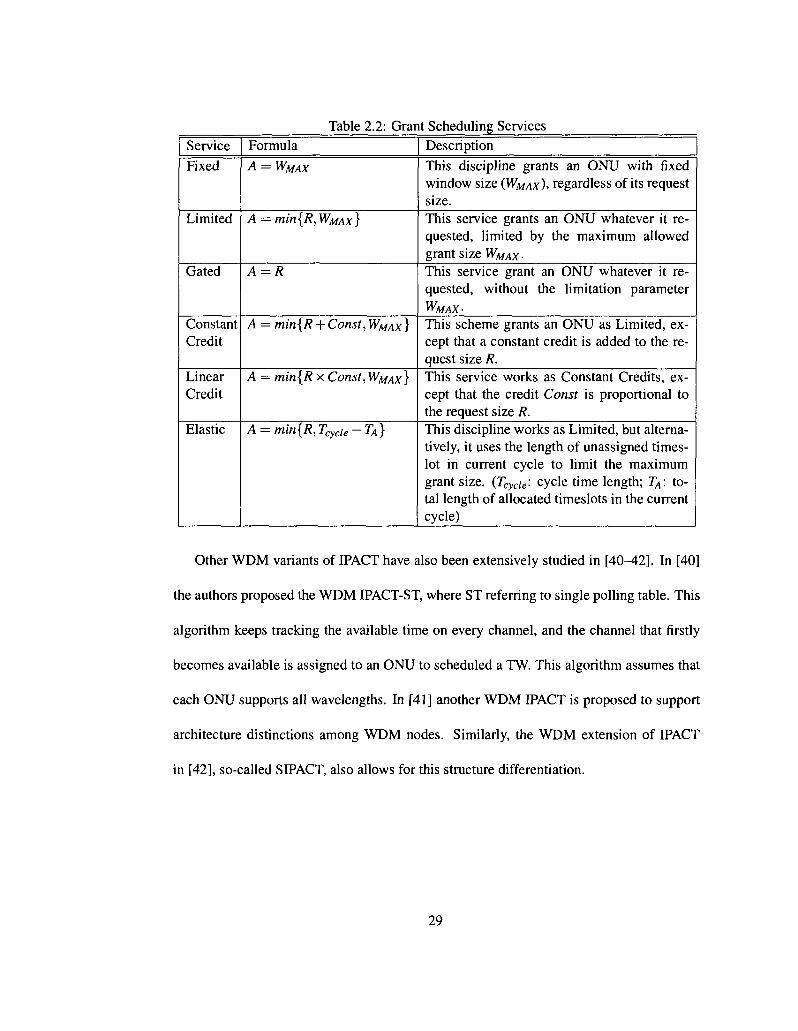
Table 2.2: Grant Scheduling Services Service Fixed
Limited
Gated
Constant Credit
Linear Credit
Elastic
Formula
A = WMAX
A = min{R,WMAx}
A = R
A = min{R + Const,WMAX }
A = min{R x Const, WMAX}
A = min{R, T^u -TA}
Description
This discipline grants an ONU with fixed window size (WMAX), regardless of its request size. This service grants an ONU whatever it requested, limited by the maximum allowed grant size WMAX-This service grant an ONU whatever it requested, without the limitation parameter WMAX-
This scheme grants an ONU as Limited, except that a constant credit is added to the request size R. This service works as Constant Credits, except that the credit Const is proportional to the request size R. This discipline works as Limited, but alternatively, it uses the length of unassigned times-lot in current cycle to limit the maximum grant size. (Tcycie: cycle time length; T^: total length of allocated timeslots in the current cycle)
Other WDM variants of IPACT have also been extensively studied in [40-42]. In [40]
the authors proposed the WDM IPACT-ST, where ST referring to single polling table. This
algorithm keeps tracking the available time on every channel, and the channel that firstly
becomes available is assigned to an ONU to scheduled a TW. This algorithm assumes that
each ONU supports all wavelengths. In [41] another WDM IPACT is proposed to support
architecture distinctions among WDM nodes. Similarly, the WDM extension of IPACT
in [42], so-called SIPACT, also allows for this structure differentiation.
29
2.5.2 Grant Sizing and Grant Scheduling
In most literature, the process of ONU-oriented bandwidth distribution in EPON is regarded
to as DBA. In [7] the author broke the DBA problem into two subproblems, namely Grant
Sizing and Grant Scheduling. The grant sizing determines how much bandwidth each ONU
can be allocated (bandwidth allocation) in a cycle. For example, services listed in Table 2.2
can be interpreted as five different grant sizing schemes.
Grant scheduling, however, it decides the start time of a TW3; in other words, it specifies
when an ONU should start its transmission in a cycle, and of course, on which wavelength.
In single channel EPONs, grant sizing and scheduling become overlapping problems since
the scheduling is greatly simplified by the grants simply being ordered in time. When
there are a number of available wavelengths, efficiently scheduling grants across multiple
wavelengths is thereby necessitated to fully utilize the network resources.
Moreover, the process of grant scheduling is further sub-categorized into scheduling
framework and scheduling policy. The scheduling framework is a logistical framework
that decides when the OUT makes scheduling decisions, whereas the scheduling policy
specifically defines how the OUT produces a schedule according to the given bandwidth
demand of a set of ONUs. Typically, both online scheduling and offline scheduling can
be regarded as different scheduling frameworks. In online scheduling, an OLT makes a
schedule decision as soon as REPORT from an ONU is received. On the other hand, in
offline scheduling, the OLT makes a decision only after all REPORTS from all ONUs are
received.
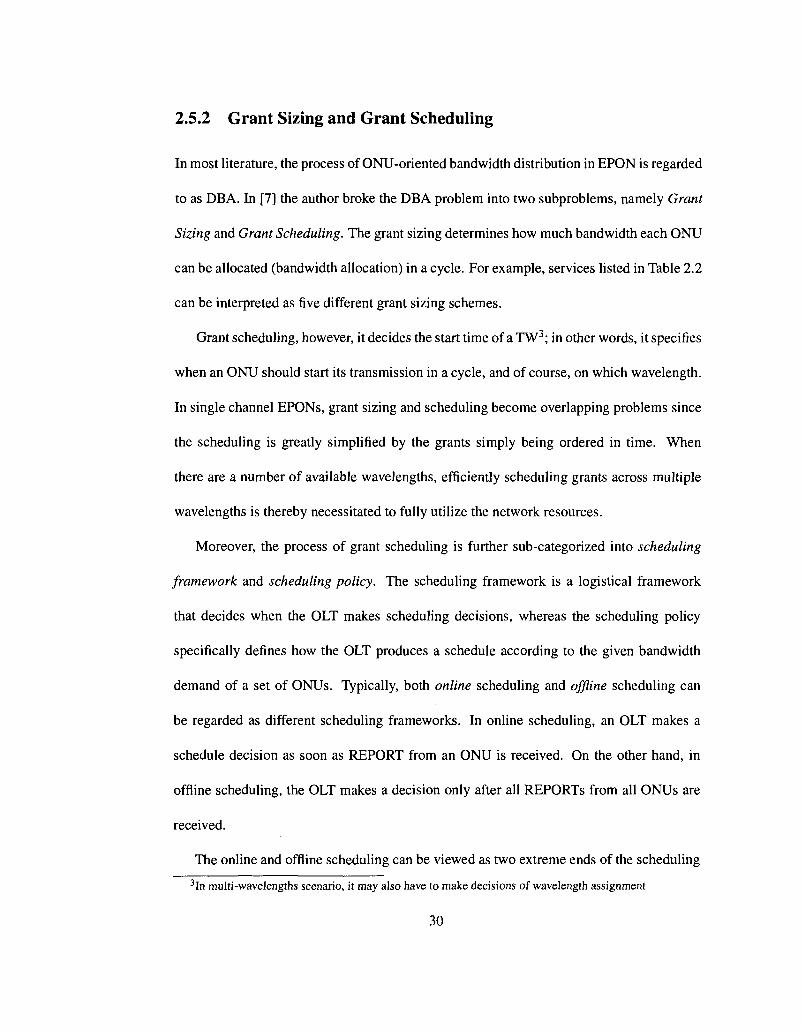
The online and offline scheduling can be viewed as two extreme ends of the scheduling 3 In multi-wavelengths scenario, it may also have to make decisions of wavelength assignment
30
control ~
Online Online JIT Offline
leasl control efficiency moderate control most control most efficient -* most efficient least efficient
1ONU 1 to (N-M) ONUs N ONUs
Figure 2.4: The Scheduling Framework Continuum (N : Number of ONUs, M: Number of Channels).
continuum as shown in Fig. 2.4 [43]. The author of [7] also proposed a novel scheduling
framework - Just-in-Time (JIT) scheduling, which is a hybrid between online and offline
scheduling. As indicated by its name, this scheme schedules ONU in a just in time fashion,
that is, the scheduling decisions are made just before any channel goes idle in the network;
by this time, all the ONUs whose REPORT are received is considered to be in the schedul
ing pool that should be assigned a TW and a wavelength, based on some given scheduling
policies.
The scheduling policies can be viewed as a set of specific rules that OLT can use to de
cide in which order ONUs should be scheduled on a set of available wavelengths. Note that,
these ONUs should firstly be determined to be schedulable by the scheduling framework.
More detail of issues on grant scheduling is referred to [43].
31

Chapter 3
Multichannel SG-EPON: Architecture
and Algorithms
3.1 Introduction
As mentioned, FTTH/B networks are built as passive optical networks (PONs) which pro
vide numerous advantages such as longevity, low attenuation, huge bandwidth, and cost
sharing of feeder fiber infrastructure and optical line terminal (OLT) equipment among
subscribers. PONs come in various flavors with Broadband PON (BPON), Gigabit PON
(GPON), and Ethernet PON (EPON) being currently installed worldwide by a number of
network operators. Significant progress has been made in terms of cost reduction, mul
tichannel upgrades of PONs by means of wavelength division multiplexing (WDM), and
design of so-called colorless optical network units (ONUs), each connecting one or more
subscribers to the PON [44]. Colorless ONUs are wavelength-independent and require ei
ther no light source at all or only a broadband light source, resulting in decreased costs,
32

simplified maintenance, and reduced stock inventory issues.
After paving in FTTH/B networks all the way to the end user with optical fiber, the
next evolutionary step is the all-optical integration of fiber-based access and metro net
works with the objective to avoid costly OEO conversion at intermediate nodes (e.g., OLT)
and thereby achieve major cost savings [19]. Very recently, research on optically integrated
access-metro network architectures and protocols has gained momentum. One of the first
research projects on the all-optical integration of access and metro edge ring networks was
the so-called Next Generation Internet Optical Network for Regional Access using Multi-
wavelength Protocols (NGI ONRAMP) testbed [20,21]. The ONRAMP network architec
ture consists of a bidirectional feeder WDM ring network which connects multiple access
nodes with one another and with the backbone network. The ONRAMP testbed implements
and demonstrates apart from optical flow switching (OFS) other features such as protection,
medium access control (MAC) protocols, control, and management. Another interesting
research project is the Stanford University access (SUCCESS) network [15]. Its design ob
jective is to provide a smooth migration path from currently widely deployed time division
multiplexing (TDM) PONs to future WDM PONs and their all-optical integration by means
of an optical single-fiber collector feeder ring, while guaranteeing backward compatibility
with existing TDM PON customer premises equipment (CPE) and providing increased
capacity to users on new WDM PONs. The so-called Metro Access Ring Integrated Net
work (MARIN) optically integrates hybrid TDM/WDM PONs into interconnected metro
access ring networks by using optical reconfigurable and parametric wavelength conversion
(PWC) devices [22]. In MARIN, metro access ring networks can dynamically share and
leverage light sources that were originally used to serve only the attached access network,
33

resulting in a more efficient utilization of network resources and improved network per
formance [23]. A new all-optical access-metro network based on optical burst switching
(OBS) was recently proposed and investigated in [24]. The optical access network segment
consists of a hybrid WDM/TDM PON with reflective ONUs, a frequency-cyclic AWG at
the remote node used as wavelength (de)multiplexer, and a tunable laser and tunable pho-
todetector stack at the OLT. Multiple WDM/TDM PONs are transparently interconnected
by using a so-called optical burst switching multiplexer (OBS-M) which optically inter
faces with a distant metro router. The OBS-M deploys an optical cross-connect (OXC) that
interfaces with the attached WDM/TDM PONs and a number of fixed wavelength convert
ers (FWCs). The OBS-M deploys a stack of tunable laser diodes to send optical continuous
wave (CW) signals to the attached reflective ONUs, each equipped with a reflective semi
conductor optical amplifier (RSOA), for remote modulation of upstream data. The basic
architecture of a single OBS-M and distant router can be extended to ail-optically inter
connect multiple OBS-Ms with a distant router through a reconfigurable optical add-drop
multiplexer (ROADM) based metro network with either a tree or a ring topology. Accord
ing to [24], the all-optical OBS based access-metro network is strictly nonblocking in the
wavelength, time, and space domains. At the downside, however, the OLT and OBS-M ar
chitectures with the required tunable laser stacks, tunable photodetector stacks, wavelength
converter banks, and OXC significantly add to the cost, power consumption, footprint, and
complexity of the all-optical access-metro network nodes.
In this chapter, we take a different approach to ail-optically integrate access and metro
networks. Instead of deploying costly active devices, e.g., OXC or FWCs, we rather rely
on low-cost passive yet powerful optical devices. The all-optical access-metro architecture
34

under consideration is referred to as STARGATE. STARGATE lets low-cost PON tech
nologies follow low-cost Ethernet technologies from EPON access networks into metro
networks, resulting in significantly reduced costs and complexity. It makes use of an over
lay island of transparency with optical bypassing capability of OLTs. The rationale behind
STARGATE and its basic operation was recently introduced in [1]. Note, however, that no
particular ONU architectures nor dynamic bandwidth allocation (DBA) algorithms were
specified in [1]. The contributions of this chapter are twofold. First, we propose three
different ONU architectures which allow STARGATE EPONs (SG-EPONs) to evolve in a
pay-as-you-grow manner while providing backward compatibility with legacy infrastruc
ture and protecting previous investment. Second, we design a DBA algorithm for SG-
EPONs and investigate its performance by means of analysis and simulation.
The remainder of this chapter is structured as follows. In Section 3.2, we provide a
brief overview of the STARGATE architecture and elaborate on the various proposed ONU
structures for SG-EPONs in Section 3.3. Section 3.4 outlines the operation of SG-EPONs
and Section 3.5 describes our proposed DBA algorithm for SG-EPONs in great details.
Results are presented in Section 3.6. Section 3.7 concludes this chapter.
3.2 STARGATE Architecture
In the following, we briefly review STARGATE. For a technically detailed description of
STARGATE the interested reader is referred to [1].
STARGATE ail-optically integrates multiple WDM/TDM EPON access networks with
a Resilient Packet Ring (RPR) metro edge ring network. RPR, specified in IEEE 802.17,
35

Figure 3.5: STARGATE network architecture.
aims at combining SONET/SDH's carrier-class functionality of high availability, reliabil
ity, and profitable TDM (voice) support with Ethernet's high bandwidth utilization, low
equipment cost, and simplicity (see [45] for further details on RPR). The rationale be
hind STARGATE is based on (i) evolutionary space division multiplexing (SDM) up
grades using additional point-to-point (P2P) or point-to-multipoint (P2MP) fiber links in
WDM/TDM EPONs, (ii) optical bypassing the OLT thus avoiding the need for OEO con
version and additional transceivers at the OLT, and (Hi) letting low-cost passive optical
networking technologies follow low-cost Ethernet technologies from access networks into
metro networks.
The network architecture of STARGATE is shown in Fig. 3.5. The RPR network com
prises P central offices (COs) that are interconnected via a single-hop WDM star subnet
work whose hub is based on a passive wavelength-broadcasting Px P passive star coupler
(PSC) in parallel with a passive athermal (i.e., temperature-insensitive) wavelength-routing
P x P AWG. Each CO is attached to a separate input/output port of the AWG and PSC by
36

means of two pairs of counterdirectional fiber links. Each fiber going to and coming from
the AWG carries AAWG = PR wavelength channels, where R denotes the number of used
free spectral ranges (FSRs) of the AWG. Each fiber going to and coming from the PSC car
ries Apse wavelength channels, consisting of one control channel ^c and a number of data
wavelength channels. All COs (except the CO bridging the RPR network to the Internet)
are collocated with a separate OLT of an attached WDM/TDM EPON. In each WDM/TDM
EPON, AOLT wavelength channels are used for communication between a given OLT and
its attached ONUs. Furthermore, each WDM/TDM EPON deploys an additional P2P or
P2MP downstream fiber link from the CO to a single ONU or multiple ONUs, respectively.
Each downstream fiber link carries AAWG wavelength channels coming from the AWG of
the star subnetwork. Note that the AAWG wavelength channels are carried on the separate
P2P/P2MP fiber link only in the downstream direction, while in the upstream direction
they are carried on the WDM/TDM EPON tree network (along with AOLT) and optically
bypass the CO and OLT and are guided directly onward to the AWG by using a WDM
coupler placed on the tree network in front of the OLT. Similarly, the AAWG wavelength
channels coming from the AWG optically bypass both CO and OLT and directly travel on
the P2P/P2MP link onward to the subset of attached ONUs. As a result, the ONU(s) at
tached to the P2P/P2MP links are able to communicate ail-optically with each other in a
single hop across the AWG of the star subnetwork, resulting in a long-reach optical island-
of-transparency overlay.
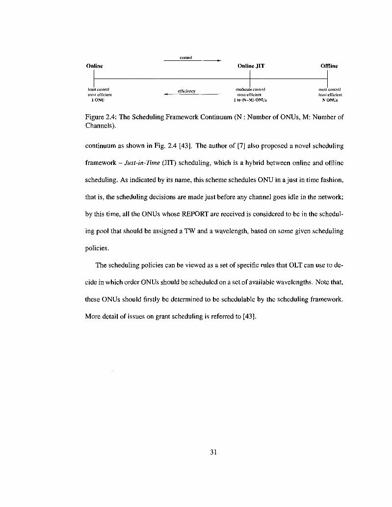
The use of wavelength-routing AWG in STARGATE provides spatial reuse of all AAWG
wavelength channels at each AWG port, which is illustrated as in Fig. 3.6 [1]. The figure
shows an 8 x 8 AWG (P = 8) and AAWG — P = 8 wavelengths. It can be easily observed
37
X8
X1...X4...X8
X1...X4...X8
Input
1 „
2 „
3 ,
4 ,
5 ,
6 „
7 f
8 ,
X1
\1
X4"
\ 8 \
1 „
2 „
3 „
4 p
5 „
6 „
7 „
8 ,
Output
Figure 3.6: Wavelength routing of an 8 x 8 arrayed waveguide grating.
that the same wavelength (e.g., X\) can be simultaneously used at two or more AWG input
ports, while the channel collisions can be avoided at the AWG output ports [1]. For exam
ple, wavelength A4 incident on input ports 1 and 2 is routed to different output ports 4 and
5, respectively. The benefits of wavelength-routing property of the AWG can be interpreted
as follows: i) due to the fact that routes of wavelengths injected into the same input port
of an AWG is independent from that of all other AWG input ports, therefore network-wide
scheduling is not required; the only necessary scheduling locates at each input port in or
der to avoid channel collisions on the AWG. ii) different wavelength channel(s) is used for
each input port to reach different output ports, this implies that AAWG wavelengths may
arrive at each AWG output port simultaneously. To avoid receiver collisions (destination
conflicts), each AWG output port must be equipped with a receiver operating on all AAWG
wavelengths. The receiver collision happens only when none of the destination node's
receivers is tuned to the wavelength on which data arrives.
In each WDM/TDM EPON, the OLT is equipped with an array of fixed-tuned trans
mitters and fixed-tuned receivers, as described in greater detail shortly. It is important to
38
note that STARGATE does not impose any particular WDM node structure on the ONU,
except for ONUs that receive data over the AWG. Those ONUs must be equipped with a
multiwavelength receiver operating on the AAWG wavelength channels in order to avoid re
ceiver collisions (destination conflicts). STARGATE does not specify any particular WDM
structure for all other ONUs, thus allowing these decisions to be dictated by economics,
current state-of-the-art transceiver manufacturing technology, traffic demands, and service
provider preferences. This approach allows for cautious pay-as-you-grow WDM upgrades
of individual ONUs and thus helps operators realize their survival strategy for highly cost-
sensitive access networks.
In each WDM/TDM EPON, IEEE 802.3ah MPCP REGISTER messages with appro
priate WDM extensions are deployed for the discovery and registration of ONUs [46].
After registration, the OLTs exchange via the PSC the MAC addresses of their attached
ONUs that are able to receive data over the AWG. As a result, all OLTs know which
MAC addresses can be reached via the AWG and to which AWG ports the correspond
ing ONUs are attached. Upstream transmission on the AOLT wavelength channels within
each WDM/TDM EPON as well as all-optical transmission on any of the AAWG wavelength
channels to an ONU located in a different EPON is arbitrated by using MPCP REPORT
and GATE messages with appropriate WDM extensions. Thus, STARGATE facilitates
dynamic bandwidth allocation (DBA) within each WDM/TDM EPON (on AOLT) as well
as among different WDM/TDM EPONs (on AAWG)- Note, however, that similar to IEEE
802.3ah EPON, STARGATE does not specify any particular DBA algorithm.
39

Figure 3.7: SG-EPON single feeder-fiber network for smooth migration from legacy TDM ONUs to WDM-enhanced ONUs and long-reach (LR) ONUs.
3.3 SG-EPON Architecture
Taking the above mentioned requirements and restrictions of STARGATE into considera
tion, we propose a cost-effective STARGATE EPON (SG-EPON) that is designed to cap
italize on the unique properties of STARGATE. SG-EPON is based on the standardized
IEEE 802.3ah EPON [34] that comprises one OLT connecting to multiple ONUs in a tree
topology manner. Nonetheless, in order to integrate SG-EPON with STARGATE, some
modifications to the OLT and ONUs need to be done. We have studied many possible so
lutions and architectures while putting an emphasis on the techno-economic factor which
most EPON architects are concerned about [47]. In addition, we have studied the hardware
cost and installation factor versus the complexity of software in EPONs and favored the
software complexity, since its cost is minimal in comparison to hardware.
Fig. 3.7 depicts the proposed SG-EPON architecture. The OLT is connected to the
ONUs using a single feeder fiber link and a passive coupler at the remote node that splits
40

and combines optical signals going to and coming from ONUs, respectively. Moreover, a
WDM coupler is placed on the shared feeder fiber link in order to guide AWG upstream
traffic sent on the AAWG wavelength channels directly onward to the AWG, possibly am
plified if needed. Recall from Section 3.2 that the purpose of this coupler is to install all-
optical communication channels between ONUs located on different WDM/TDM EPONs.
This is done by bypassing the OLT and connecting directly to the AWG of the metro net
work of STARGATE, resulting in an all-optical single-hop path between these ONUs and
thereby eliminating costly OEO conversions at the CO and OLT. The OLT as well as ONU
structures are described in greater detail in the following.
3.3.1 ONU
SG-EPON is designed to enable a smooth migration path where nodes (OLT and ONUs)
are upgraded in a pay-as-you-grow manner according to given traffic demands and/or cost
constraints, while at the same time protecting existent ONU infrastructure investment. As
outlined in greater detail shortly, current legacy TDM EPON ONUs typically deploy a
laser diode (e.g., Fabry-Perot) and photodetector operating on two different coarse WDM
(CWDM) wavelength channels. The objective of our proposed evolutionary upgrade ap
proach is to build on these widely installed ONU transceivers rather than replacing them.
As we will see shortly, this approach not only protects existent infrastructure investment
and extends its amortization period but also helps improve the network performance con
siderably.
For increased flexibility, we allow an SG-EPON to comprise different types of ONUs
41

with different specifications and capabilities. In the following, we introduce three different
types of ONUs which can be customized according to given network needs and cost con
straints. Note that any of the following ONUs can be smoothly upgraded from one type to
another, depending on given network requirements and preferences.
TDM ONU
A TDM ONU is identical to an ONU found in widely deployed legacy single-channel TDM
EPONs. As shown in Fig. 3.7, a TDM ONU is equipped with one fixed-tuned transmitter
TXJDM to send upstream data and control traffic to the OLT on upstream wavelength chan
nel ^-TDM' anc* o n e fixed-tuned receiver RXTDM to receive downstream data and control
traffic from the OLT on downstream wavelength channel ^J°DM- Each TDM ONU may
have multiple queues, each designated for a specific class of service (CoS). However, in
this work we do not consider quality-of-service (QoS) differentiation. Thus, we assume
that each TDM ONU is equipped with one queue to store incoming end user data packets.
WDM ONU
A WDM ONU has the same transmitting and receiving capabilities as the TDM ONU, i.e.,
one transmitter for y?jDM and one receiver for A,^^. In addition, a WDM ONU is designed
to operate on multiple wavelengths (designated for ONUs with high traffic demand and/or
higher number of users), in both the downstream and the upstream directions. This could
be achieved by installing an array of fixed-tuned transmitters, one for each upstream wave
length channel, and an array of fixed-tuned receivers, one for each downstream wavelength
channel. Clearly, this approach limits the smooth upgrade of the ONU, especially if more
42

wavelengths need to be added in the future to accommodate more users and increased band
width demands. Many alternatives have been studied with the design objective to achieve
a more scalable ONU structure, while meeting low-cost cost requirements [46, 48-53].
One of the most promising low-cost ONU design solutions is the one that uses a reflective
semiconductor optical amplifier (RSOA) for remote modulation of upstream data [53].
RSOAs are widely considered a strong candidate for realizing future low-cost ONUs in
FTTH networks. An RSOA is much cheaper than a tunable laser diode and is expected to
have similar cost to a fixed-tuned one. Moreover, it was shown that, considering expected
prices of optical components, a WDM PON using an AWG as wavelength demultiplexer at
the remote node and RSOA based ONUs has costs similar to a power splitter based TDM
PON [47]. WDM PONs using an 1 x N AWG as wavelength demultiplexer at the remote
node and RSOA based ONUs, such as that in [24], provides some advantages, e.g., each
of the N attached ONUs has a secure point-to-point wavelength channel. At the downside,
however, WDM PONs based on a 1 x iV AWG suffer from several shortcomings. Among
others, each wavelength channel is dedicated to a different ONU and thus can not be shared
by other ONUs, leading to (/) scalability issues since the number of required wavelength
channels has to be equal to the number of ONUs and (//) low wavelength utilization un
der bursty, unbalanced, and/or low traffic loads due to the lack of statistical multiplexing
gain. To improve the wavelength utilization, SG-EPON leaves the coupler found in most
of today's EPON tree networks untouched, thus allowing each wavelength channel to be
shared and dynamically assigned to all ONUs, whereby the number of wavelength chan
nels is independent of the number of ONUs. As shown in Fig. 3.7, WDM ONUs deploy
an additional RSOA with a tunable bandpass filter (BPF) placed in front of it to select any
43
of the W WDM wavelength channels X\,...,Xw- Note that the W wavelength channels are
used in addition to the two legacy TDM channels ^ m / ^ " f° r uP s t r e am and downstream
transmission of data traffic only. Control traffic between OUT and WDM ONUs is sent
on the legacy TDM channels for backward compatibility with IEEE 802.3ah MPCP [46].
Similar to TDM ONUs, we assume that each WDM ONU deploys one queue to store in
coming user data packets. Nonetheless, the selection of packets is synchronized between
the RSOA and the fixed-tuned transmitter TXTDM since both simultaneously operate on dif
ferent wavelengths. Finally note that moving the AWG from the remote node of each PON
towards the metro area and use it as a multiport wavelength router (rather than wavelength
demultiplexer) enables extensive spatial wavelength reuse, where each wavelength chan
nel can be simultaneously used at all AWG ports without resulting in channel collisions,
translating into a dramatically increased number of available communication channels and
network capacity.
LRONU
A long-reach (LR) ONU has the same transmitting and receiving capabilities as a WDM
ONU. In addition, an LR ONU has the capability of ail-optically communicating to another
LR ONU in a different or in the same WDM/TDM EPON (e.g., for bulk data transfer such
as database synchronization or file sharing). As shown in Fig. 3.7, a multiwavelengfh
receiver RXLR operating on all KAWG wavelength channels is used to enable receiving
downstream data traffic coming from the AWG. Furthermore, the BPF of the RSOA is now
tunable over the wavelength channels X\,..., h/v+t, where W denotes the above mentioned
WDM wavelength channels and L denotes the number of additional wavelength channels
44
used for optical upstream data transmission across the AWG (i.e., L = AAWG = P-R)-
On the intra-ONU level, in addition to the queue used to store TDM and WDM wave
length traffic, each LR ONU is equipped with a separate buffer for each destination SG-
EPON. In other words, each LR ONU deploys L additional virtual output queues (VOQs).
The deployment of L VOQs is done in order to classify packets according to the desti
nation SG-EPON (packet classification is described in greater details shortly). Similar to
WDM ONUs, the selection of packets is synchronized between the RSOA and the legacy
fixed-tuned transmitter TXTDM-
3.3.2 OLT
Similar to ONUs, the OLT will be exposed to evolutionary add-ons to accommodate the up
grades of the shared media (TDM, WDM, and AWG wavelength channels) and of ONUs
with respect to both hardware and software (i.e., wavelength and bandwidth assignment),
as shown in Fig. 3.7 [54], Besides using a circulator to separate upstream and downstream
wavelengths in conjunction with a wavelength multiplexer (MUX) and demultiplexer (DE-
MUX), the OLT is equipped with one fixed-tuned transmitter TXJDM dedicated for the
downstream transmission of data and control traffic on legacy wavelength 'Kj0^ and one
fixed-tuned receiver RXTDM for receiving upstream data and control traffic on legacy wave
length y^fDM. In addition, an array of W fixed-tuned WDM transmitters TXWDM plus L
fixed-tuned long-reach transmitters TXLR is deployed to send downstream data as well as
optical continuous wave (CW) signals (to be remotely modulated by the ONUs' RSOAs
for upstream data transmission, as discussed in greater detail shortly) on the wavelengths
45
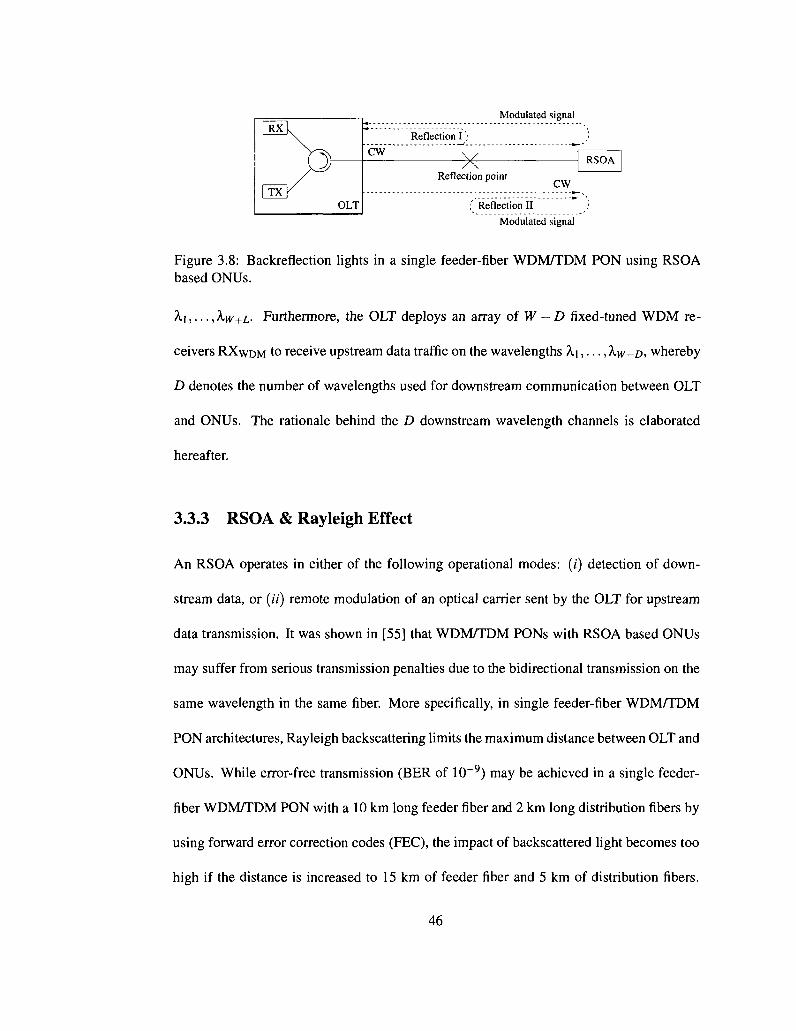
| R X l
| TX Y
(\
OLT
CW
Reflection I )
V Reflection
Modulated
point
.' Reflection II
signal
CW
_)
RSOA
Modulated signal
Figure 3.8: Backreflection lights in a single feeder-fiber WDM/TDM PON using RSOA based ONUs.
X\,..., XW+L- Furthermore, the OLT deploys an array of W — D fixed-tuned WDM re
ceivers RXWDM to receive upstream data traffic on the wavelengths X\,..., XW-D, whereby
D denotes the number of wavelengths used for downstream communication between OLT
and ONUs. The rationale behind the D downstream wavelength channels is elaborated
hereafter.
3.3.3 RSOA & Rayleigh Effect
An RSOA operates in either of the following operational modes: (/) detection of down
stream data, or (if) remote modulation of an optical carrier sent by the OLT for upstream
data transmission. It was shown in [55] that WDM/TDM PONs with RSOA based ONUs
may suffer from serious transmission penalties due to the bidirectional transmission on the
same wavelength in the same fiber. More specifically, in single feeder-fiber WDM/TDM
PON architectures, Rayleigh backscattering limits the maximum distance between OLT and
ONUs. While error-free transmission (BER of 10~9) may be achieved in a single feeder-
fiber WDM/TDM PON with a 10 km long feeder fiber and 2 km long distribution fibers by
using forward error correction codes (FEC), the impact of backscattered light becomes too
high if the distance is increased to 15 km of feeder fiber and 5 km of distribution fibers.
46
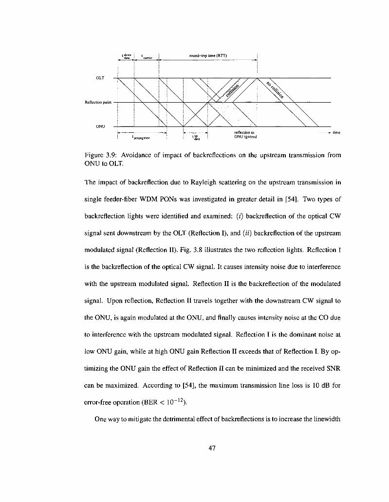
Reflection point
Figure 3.9: Avoidance of impact of backreflections on the upstream transmission from ONU to OLT.
The impact of backreflection due to Rayleigh scattering on the upstream transmission in
single feeder-fiber WDM PONs was investigated in greater detail in [54]. Two types of
backreflection lights were identified and examined: (f) backreflection of the optical CW
signal sent downstream by the OLT (Reflection I), and (if) backreflection of the upstream
modulated signal (Reflection II). Fig. 3.8 illustrates the two reflection lights. Reflection I
is the backreflection of the optical CW signal. It causes intensity noise due to interference
with the upstream modulated signal. Reflection II is the backreflection of the modulated
signal. Upon reflection, Reflection II travels together with the downstream CW signal to
the ONU, is again modulated at the ONU, and finally causes intensity noise at the CO due
to interference with the upstream modulated signal. Reflection I is the dominant noise at
low ONU gain, while at high ONU gain Reflection II exceeds that of Reflection I. By op
timizing the ONU gain the effect of Reflection II can be minimized and the received SNR
can be maximized. According to [54], the maximum transmission line loss is 10 dB for
error-free operation (BER < 10~12).
One way to mitigate the detrimental effect of backreflections is to increase the linewidth
47
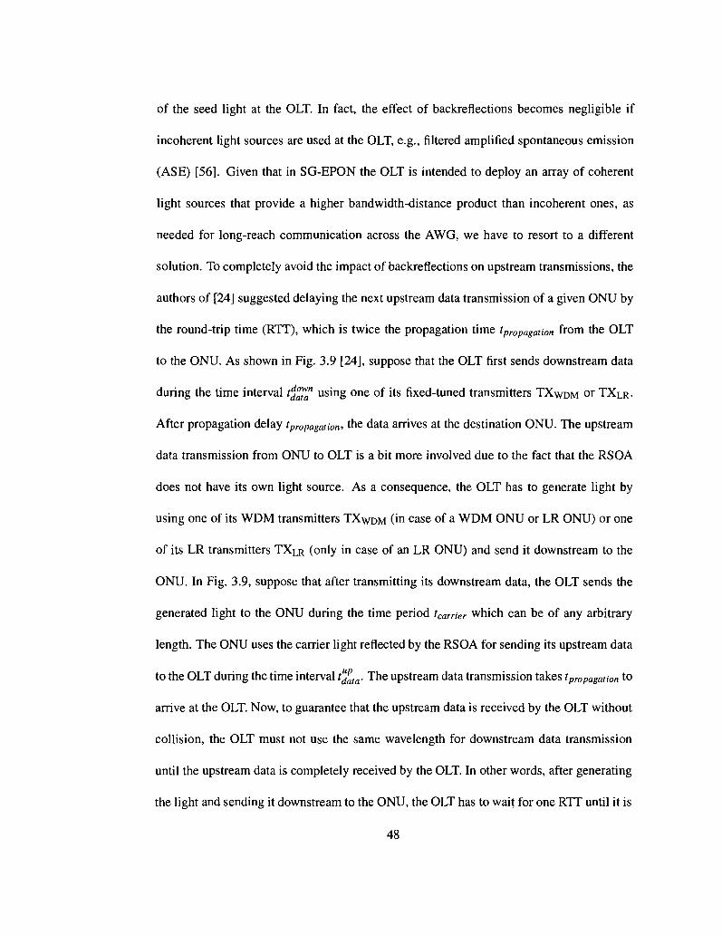
of the seed light at the OLT. In fact, the effect of backreflections becomes negligible if
incoherent light sources are used at the OLT, e.g., filtered amplified spontaneous emission
(ASE) [56]. Given that in SG-EPON the OLT is intended to deploy an array of coherent
light sources that provide a higher bandwidth-distance product than incoherent ones, as
needed for long-reach communication across the AWG, we have to resort to a different
solution. To completely avoid the impact of backreflections on upstream transmissions, the
authors of [24] suggested delaying the next upstream data transmission of a given ONU by
the round-trip time (RTT), which is twice the propagation time tpropa&atwn from the OLT
to the ONU. As shown in Fig. 3.9 [24], suppose that the OLT first sends downstream data
during the time interval t^™" using one of its fixed-tuned transmitters TXWDM or TXLR.
After propagation delay tpropagation, the data arrives at the destination ONU. The upstream
data transmission from ONU to OLT is a bit more involved due to the fact that the RSOA
does not have its own light source. As a consequence, the OLT has to generate light by
using one of its WDM transmitters TXWDM (in case of a WDM ONU or LR ONU) or one
of its LR transmitters TXLR (only in case of an LR ONU) and send it downstream to the
ONU. In Fig. 3.9, suppose that after transmitting its downstream data, the OLT sends the
generated light to the ONU during the time period tcarrier which can be of any arbitrary
length. The ONU uses the carrier light reflected by the RSOA for sending its upstream data
to the OLT during the time interval tufaia. The upstream data transmission takes tpropagation to
arrive at the OLT. Now, to guarantee that the upstream data is received by the OLT without
collision, the OLT must not use the same wavelength for downstream data transmission
until the upstream data is completely received by the OLT. In other words, after generating
the light and sending it downstream to the ONU, the OLT has to wait for one RTT until it is
48

allowed to use the same wavelength again for downstream transmission of data. To better
understand this constraint, Fig. 3.9 illustrates the case where the OLT does not wait for one
RTT and starts its next downstream data transmission before one RTT has elapsed. The
second downstream data transmission might be reflected at a reflection point (e.g., splice
or connector) somewhere between the OLT and ONU and interfere with the upstream data
transmission of the ONU, resulting in a collision. Clearly, by deferring its next downstream
data transmission by at least one RTT the OLT can avoid any collisions. However, note that
while waiting for the wavelength to become available, the OLT may use the downstream
wavelength channel Xfj^ to send data to any WDM, LR, and TDM ONU. Also note that
this restriction holds only for data but not for carrier sent in the downstream direction.
For instance, in Fig. 3.9 the OLT might generate a second carrier on the same wavelength
destined for a different ONU right after tcarrier, provided that the upstream data transmission
of the second ONU does not overlap with the first one due to different propagation delays
between OLT and the two ONUs.
This solution is straightforward and efficient as in [24] due to the fact that wavelengths
are dedicated to each WDM ONU. However, some performance penalty is observed due
to the RTT delay, especially in the case of shared wavelength resources among all WDM
and LR ONUs. Applying this solution in SG-EPON, the OLT has to wait for one RTT
between two consecutive CWs for two different ONUs ready to send on the same wave
length channel, leading to a waste of bandwidth. To overcome this problem, we propose a
simple solution that meets the hardware restrictions of SG-EPON. We dispose 0 < D < W
wavelengths (see Fig. 3.7) for the OLT to send downstream data (but no CW) to LR ONUs
and WDM ONUs, i.e., the D wavelength channels cannot be used by ONUs for upstream
49
data transmission by means of remote modulation. Not only will this solve the problem,
but also it will improve the bandwidth utilization. As a result, in its detection mode, the
RSOA of an LR ONU or a WDM ONU will detect unmodulated CWs sent by the OUT on
the remaining W — D + LorW — D wavelength channels and will then perform the remote
modulation and upstream data transmission on any of the W — D + L or W — D wavelength
channels, respectively.
Clearly, SG-EPONs must take these constraints into account in order to efficiently uti
lize the available network resources, as discussed next.
3.4 SG-EPON Operation
Similar to IEEE 802.3ah EPON, SG-EPON has two modes of operation: (/) auto-discovery
and registration, where the OLT learns about its connected ONUs and their hardware ca
pabilities (i.e., number of transmitters/receivers, their tuning range, etc.) [34]. This infor
mation is mapped into the reserved fields of the REGISTER_REQ MPCP protocol data
unit (PDU) which is WDM extended as recommended in [46]; and (ii) normal (on-service)
operation, where the OLT utilizes the MPCP REPORT and GATE PDUs to arbitrate the
transmission of ONUs in the upstream direction. These two operation modes are mainly
applied with TDM and WDM ONUs. For LR ONUs, however, we extend the registration
mode to include a provisioning phase where they have to acquire some information from
the OLT. Both provisioning and on-service phases are described in greater details in the
following.
50
3.4.1 Provisioning Phase
In the initialization phase, each OCT gathers information about ONUs local to its WDM/TDM
EPON and broadcasts this information on the PSC to all other OLTs [1]. More specifically,
each OLT shares with the other OLTs how many ONUs it is connected to, and which ones
are LR ONUs, including their MAC addresses and logical link identifiers (LLIDs). In
doing so, each OLT is provisioned with a routing table that contains information about
all WDM/TDM EPONs connected to the metro network. This table is used by the DBA
algorithm (to be defined shortly) when assigning transmission grants to ONUs. This infor
mation is in turn broadcast by the OLT to its local ONUs. TDM and WDM ONUs may
ignore it since it is mainly designated for LR ONUs that will use this information for their
traffic classifiers. Hence, unlike TDM and WDM ONUs, LR ONUs are provisioned with
routing information (MAC address, LLID, appropriate wavelength channel in AAWG) about
remote ONUs residing in different WDM/TDM EPONs.
3.4.2 On-Service Phase
Similar to IEEE 802.3ah EPON, SG-EPON uses MPCP to exchange control messages be
tween ONUs and OLT. MPCP defines a polling-based access mechanism to facilitate dy
namic bandwidth allocation for upstream data transmissions. MPCP makes use of two
messages: REPORT and GATE. The OLT broadcasts GATE messages to the ONUs spec
ifying the assigned transmission window (TW) start time and length. Each ONU strips
these grants based on its unique LLID and transmits traffic in the upstream direction ac
cordingly. It then reports its current traffic requirements (queue occupancies) using the
51

REPORT message at the end of its assigned window. For backward compatibility with
conventional TDM EPONs, we run MPCP on the legacy wavelength channels ^DM and
K°DM w h i c h a r e shared by all types of ONUs. More precisely, Xfgfi, is used by the OLT
to broadcast GATE messages as well as downstream data traffic. In addition to sending
upstream data traffic, ^jDM is used by any type of ONU to send REPORT messages. In
SG-EPON, MPCP is extended to support both the time and wavelength domains by us
ing the WDM extensions recommended in [46]. The OLT allocates TWs to each ONU
based on its hardware capability and compliance with available resources. It is impor
tant to note that instead of specifying a particular DBA algorithm, MPCP only provides
a control framework for developing a wide range of bandwidth allocation schemes. The
design of a specific DBA algorithm is left to manufacturers and equipment vendors. For
an overview of DBA algorithms proposed for WDM/TDM EPONs the interested reader is
referred to [48,57-59].
3.5 DBA in SG-EPON
Having presented the SG-EPON architecture and its operation, a DBA algorithm is required
to arbitrate the transmission of ONUs over the available shared wavelength channels. The
OLT is responsible for assigning both bandwidth (to all ONUs) in addition to wavelengths
(to WDM ONUs and LR ONUs) for upstream transmission.
Due to the hardware constraints imposed by SG-EPON, a DBA algorithm has to resolve
many challenges. In the following, we outline the main factors that any DBA algorithm in
SG-EPON needs to consider in order to provide efficient and fair scheduling of upstream
52
transmissions:
1. The fact that there exists various shared resources makes the OLT the best candidate
responsible for keeping track of all these resources in terms of bandwidth availability,
fair sharing and congestion control as well as wavelength selection and availability.
2. The existence of various types of ONUs sharing various resources makes the OLT
responsible for assigning different TWs on different wavelength channels. For in
stance, TDM ONUs are scheduled on the TDM wavelength channel only while
WDM ONUs are scheduled on the TDM and WDM wavelength channels and LR
ONUs are scheduled on the TDM, WDM and AWG wavelength channels.
3. The deployment of one RSOA per WDM ONU or LR ONU, makes the arbitration of
these ONUs over the AWG and WDM wavelength channels to be hardware depen
dent. For instance, the OLT has to take into account that it is impossible to assign
two simultaneous TWs for a given WDM ONU or LR ONU. Furthermore, the DBA
algorithm has to compensate for the consequence of such a restriction, which can
result in waste of bandwidth, and should mitigate this fact by allowing, for instance,
excess bandwidth allocation [48,57] and/or deciding to move traffic from one over
loaded wavelength to another lightly loaded one, while keeping track of all TWs on
all wavelength channels.
3.5.1 Preliminaries
Let us first define the various parameters used by our proposed DBA algorithm for band
width and wavelength allocation:
53
• N: Total number of ONUs in SG-EPON.
• NTDM- Total number of TDM ONUs, where 0 < NTDM < N.
• NWDM'- Total number of WDM ONUs, where 0 < NWDM < N.
• NLR: Total number of LR ONUs, where 0<NLR< N.
• L: Total number of available AWG wavelength channels in AAWG', hence, total num
ber of AWG queues at each LR ONU equals L.
• W: Total number of WDM wavelength channels in AOLT-
• D: Total number of downstream WDM wavelength channels.
Similar to other DBA algorithms presented for EPON in the literature, and in particular
IPACT [60], time is divided into cycles (of maximum length TMAX) and ONUs in each
SG-EPON are allocated transmission opportunities in each cycle according to their band
width requirements (buffer occupancies). Specifically, each TDM and WDM ONJJi reports
B\eq{n — 1), since they have one buffer for traffic that is sent to the OLT, where n is the cycle
number. In addition to B'req(n— 1), each LR ONUt reports Breq(n— 1) (/ = 1,...,L), where
AWG traffic, i.e., traffic sent across the AWG, is classified based on the MAC address in
the packet header and is subsequently buffered in the corresponding AWG queue. As we
mentioned earlier, all the REPORTs and GATEs are sent on the legacy TDM wavelengths.
Upon receiving the REPORTs from all ONUs, the OLT runs the DBA algorithm to
schedule transmissions in cycle n for these ONUs. If ONUt is a TDM ONU, it will be
assigned a window with start time tstart '' and length th t£ on the TDM channel. If it is
54
a WDM ONU, in addition to t™%'' and t]™g, the OLT has the choice of allocating one
or more windows on one or more of the W — D WDM wavelengths. Indeed, assigning
more than one channel per cycle to a WDM ONU is feasible but introduces some overhead
resulting from tuning the BPF when switching between wavelengths. Accordingly, our
DBA assigns only one WDM wavelength Xj, and hence a transmission window tj^n and
tlength P e r e a c n WDM or LR ONUt in one cycle. As a result, each upstream WDM channel
is shared on average by no more than NL^-D)M ONUs. Finally, if ONUj is an LR ONU
then in addition to tjtart '', t{ t£, tj^rt ana" t^ th, *l w ^ ' be aH°ca t ed a window of tJart a nd
tlength f° r e a c n ° tne corresponding AWG wavelength X[(l = 1, ...,L), which ail-optically
interconnects source and destination LR ONUs.
As mentioned above, the OLT is responsible for assigning wavelength channels to
WDM and LR ONUs in addition to TWs. Note that the WDM wavelength selection differs
from that of the AWG. For the WDM wavelength selection, the OLT maintains a variable
for every channel, which is the channel free time 7V g [48] of wavelength \j where the next
transmission is possible on this particular channel. For every REPORT message received
from any WDM ONU, the OLT allocates a channel with the smallest T^ee to this ONU
and also determines the length (e.g., in bytes) of the transmission window allocated to this
ONU on the assigned wavelength channel. On the other hand, the wavelength selection for
LR ONUs on the AWG wavelengths is destination-dependent. Thus, each LR ONU will be
assigned a window together with a wavelength A,/ that interconnects the source LR ONU
with the corresponding AWG port to which the destination LR ONU is attached to.
55
3.5.2 Minimum Bandwidth Guaranteed
Indeed, our main objective is to design an efficient, and yet simple, DBA algorithm where
the three factors mentioned previously are taken into account. For this purpose, we choose
the grant length allocation to be based on the limited service, as proposed in [34]. In our
DBA algorithm, each ONU is either granted what requested, or a minimum guaranteed
bandwidth Bm,„ as in [57]. Bmin is dependent on the weight assigned to each ONU based
on the Service Level Agreement (SLA) between the service provider (SP) and users. For
simplicity, we consider equal weights for all ONUs.
Each type of wavelength (TDM, WDM, or AWG) is shared by a different number of
ONUs. The TDM channel is shared among NTDM + NWDM + NLR ONUs. Hence,
( = (Tcycie - (NTDM+NWDM+NLR) X Tg) X RN
min~ Sx(NTDM+NWDM + NLR) ' U
where RN (given in Mb/s) denotes the data rate, Tcycie denotes the cycle time, and Tg is
the guard time that separates the TWs of two consecutive ONUs. Now, the minimum
guaranteed bandwidth on an AWG wavelength A,/, assuming A,/ is shared by all LR ONUs
in the same EPON, is:
('cycle
NLR x Tg) x RN
8 x Nut
no _ K'cycle "LK ~ *gj ~ 'W ._. amin- TT—Tr • U )
Clearly, an LR ONU may be allocated with as much as L x Bamin in a cycle on all AWG
wavelengths. Notice that if L x Bamin is close to 7 ^ ^ , then the RSOA at that ONU is always
busy transmitting AWG traffic. Since there is only one RSOA at each LR ONU, then the
remaining WDM wavelengths cannot be used by this ONU in the same cycle. Therefore,
56

we modify the computation of Bamin to consider the number of WDM wavelengths an ONU
may use during one cycle:
a _(Tcycie-NL/ixTg)xRN
where Wk can be the number of either one or more WDM wavelengths selected for upstream
and downstream transmission (as described before). Since each LR ONU is not allowed
to be allocated more than Bamin, then the minimum bandwidth guaranteed for LR ONUs on
AWG and WDM channels is the same.
Similarly, each upstream WDM wavelength channel "kj can either be shared by NIR +
NLR+NWDM (W-D) NWDM ONUs or by no more than
guaranteed on Xj is computed as follows
ONUs. Therefore, the minimum bandwidth
Rw,up _ (Tcycle ~ (NLR+NWDM) X Tg) X RN
Since we are assigning D WDM wavelengths for downstream data, the OUT is also re
sponsible for providing a bandwidth allocation scheme on these D wavelengths. As a result,
the size of downstream TWs will be also bounded by a minimum bandwidth guaranteed
B%?n\ such that,
Rw,ds _ (Tcycle ~ {NLR+NWDM) X Tg) X RN
min~ *x(NLK + NWDM) • C )
57

3.5.3 Bandwidth Allocation
Upon receiving a REPORT message from any ONUi, the OLT checks the type of this ONU.
If ONUi is a TDM ONU, then the allocated bandwidth A\ on the TDM channel is computed
as follows
AJ = min(4ei?,B'm,.J, (6)
If ONUi is a WDM ONU, the allocation is achieved differently. For the assignment of "non-
AWG" traffic (i.e., traffic that is not sent across the AWG), due to the fact that the WDM
channels are shared by less ONUs than the TDM channel and because they possess more
bandwidth, the DBA algorithm tries to satisfy each ONU on the WDM channels first, then
on the TDM channel. This will allow for an inter-channel statistical multiplexing, which
will increase the bandwidth efficiency of our proposed DBA algorithm. More specifically,
upon receiving a REPORT message from any WDM ONUi, the OLT assigns bandwidth for
cycle n based on the following conditions:
i. ureq s amin
l- bmin < areq S «m ,„ + Omin
1 R' ~> RW'UP 4- R' J- "req ^ °min ' min
Consequently, the assigned bandwidth for the WDM ONUi on a WDM channel is computed as
follows:
Breq ifD (7)
BZf if 2) or 3).
58
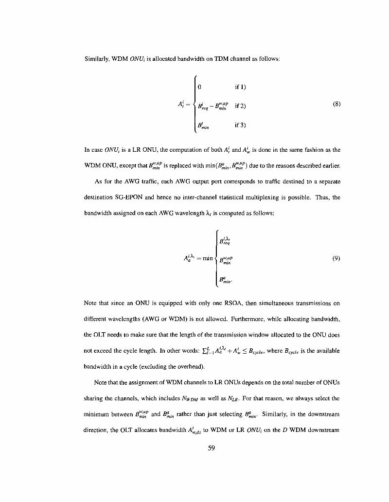
Similarly, WDM ONUj is allocated bandwidth on TDM channel as follows:
A\={
if l)
#„q-BZP if 2) (8)
BL if 3)
In case ONUj is a LR ONU, the computation of both A\ and A'w is done in the same fashion as the
WDM ONU, except that B^"np is replaced with Tcun(B^lin,B^^>) due to the reasons described earlier.
As for the AWG traffic, each AWG output port corresponds to traffic destined to a separate
destination SG-EPON and hence no inter-channel statistical multiplexing is possible. Thus, the
bandwidth assigned on each AWG wavelength Xi is computed as follows:
, i,Xi •• m i n <
B req
nW,up min
Bl
(9)
Note that since an ONU is equipped with only one RSOA, then simultaneous transmissions on
different wavelengths (AWG or WDM) is not allowed. Furthermore, while allocating bandwidth,
the OLT needs to make sure that the length of the transmission window allocated to the ONU does
not exceed the cycle length. In other words: £f=1 Aj,' ' +A'W < Bcycie, where BcyCie is the available
bandwidth in a cycle (excluding the overhead).
Note that the assignment of WDM channels to LR ONUs depends on the total number of ONUs
sharing the channels, which includes NWDM as well as A^ . For that reason, we always select the
minimum between B^"f and fi^(n rather than just selecting B^jn. Similarly, in the downstream
direction, the OLT allocates bandwidth Alwds to WDM or LR ONUt on the D WDM downstream
59
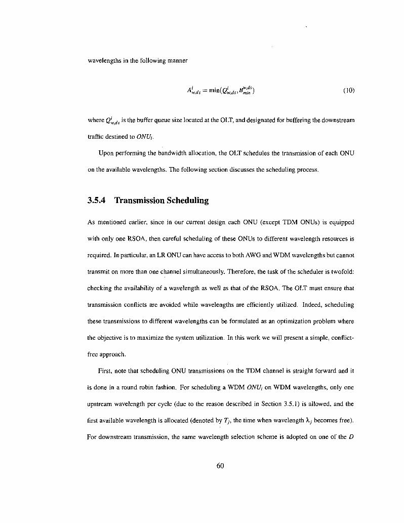
wavelengths in the following manner
A ^ = min(2'Mi.Cf) (10)
where Q'wds is the buffer queue size located at the OLT, and designated for buffering the downstream
traffic destined to ONUj.
Upon performing the bandwidth allocation, the OLT schedules the transmission of each ONU
on the available wavelengths. The following section discusses the scheduling process.
3.5.4 Transmission Scheduling
As mentioned earlier, since in our current design each ONU (except TDM ONUs) is equipped
with only one RSOA, then careful scheduling of these ONUs to different wavelength resources is
required. In particular, an LR ONU can have access to both AWG and WDM wavelengths but cannot
transmit on more than one channel simultaneously. Therefore, the task of the scheduler is twofold:
checking the availability of a wavelength as well as that of the RSOA. The OLT must ensure that
transmission conflicts are avoided while wavelengths are efficiently utilized. Indeed, scheduling
these transmissions to different wavelengths can be formulated as an optimization problem where
the objective is to maximize the system utilization. In this work we will present a simple, conflict-
free approach.
First, note that scheduling ONU transmissions on the TDM channel is straight forward and it
is done in a round robin fashion. For scheduling a WDM ONUj on WDM wavelengths, only one
upstream wavelength per cycle (due to the reason described in Section 3.5.1) is allowed, and the
first available wavelength is allocated (denoted by 7), the time when wavelength Xj becomes free).
For downstream transmission, the same wavelength selection scheme is adopted on one of the D
60
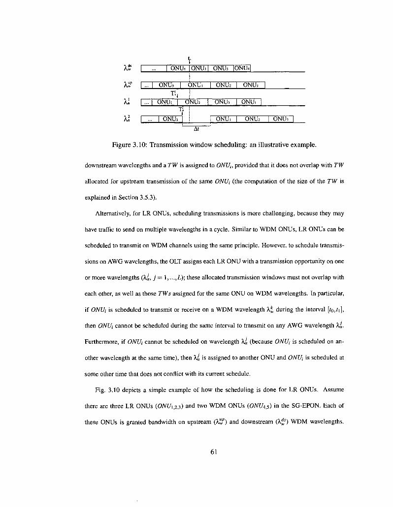
Aw I ... | ONUs | ONU.
•P.,
I ... | ONU. | ONU2 | Tl
\ ... | ONU3 |
ONU2
ONLb
ONUi
( ONUs |
ONUi |
ONU2 | ONU? 1
At
Figure 3.10: Transmission window scheduling: an illustrative example.
downstream wavelengths and a TW is assigned to ONUi, provided that it does not overlap with TW
allocated for upstream transmission of the same ONUi (the computation of the size of the TW is
explained in Section 3.5.3).
Alternatively, for LR ONUs, scheduling transmissions is more challenging, because they may
have traffic to send on multiple wavelengths in a cycle. Similar to WDM ONUs, LR ONUs can be
scheduled to transmit on WDM channels using the same principle. However, to schedule transmis
sions on AWG wavelengths, the OUT assigns each LR ONU with a transmission opportunity on one
or more wavelengths (X«, j = 1, ...,L); these allocated transmission windows must not overlap with
each other, as well as those TWs assigned for the same ONU on WDM wavelengths. In particular,
if ONUi is scheduled to transmit or receive on a WDM wavelength X* during the interval [to,t\],
then ONUi cannot be scheduled during the same interval to transmit on any AWG wavelength ~kJa.
Furthermore, if ONUi cannot be scheduled on wavelength XJa (because ONUi is scheduled on an
other wavelength at the same time), then Xi is assigned to another ONU and ONUi is scheduled at
some other time that does not conflict with its current schedule.
Fig. 3.10 depicts a simple example of how the scheduling is done for LR ONUs. Assume
there are three LR ONUs (ONUw) and two WDM ONUs (CWl/4,5) in the SG-EPON. Each of
these ONUs is granted bandwidth on upstream (kwP) and downstream (k^s) WDM wavelengths.
61
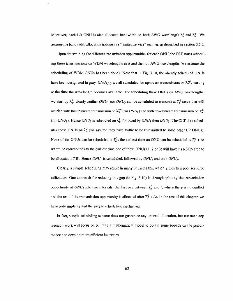
Moreover, each LR ONU is also allocated bandwidth on both AWG wavelength A,] and A2,. We
assume the bandwidth allocation is done in a "limited service" manner, as described in Section 3.5.2.
Upon determining the different transmission opportunities for each ONU, the OUT starts schedul
ing these transmissions on WDM wavelengths first and then on AWG wavelengths (we assume the
scheduling of WDM ONUs has been done). Note that in Fig. 3.10, the already scheduled ONUs
have been designated in gray. ONUX^T, are all scheduled for upstream transmission on Kf, starting
at the time the wavelength becomes available. For scheduling these ONUs on AWG wavelengths,
we start by X, ; clearly neither ONU\ nor ONU3 can be scheduled to transmit at T* since that will
overlap with the upstream transmission on A.if (for ONU\) and with downstream transmission on X^f
(for ONU3). Hence ONU2 is scheduled on X\, followed by ONU3 then ONU\. The OLT then sched
ules these ONUs on X\ (we assume they have traffic to be transmitted to some other LR ONUs).
None of the ONUs can be scheduled at T}\ the earliest time an ONU can be scheduled is T^ + At
where A? corresponds to the earliest time one of these ONUs (1, 2 or 3) will have its RSOA free to
be allocated a TW. Hence ONU\ is scheduled, followed by ONU2 and then ONU3.
Clearly, a simple scheduling may result in many unused gaps, which yields to a poor resource
utilization. One approach for reducing this gap (in Fig. 3.10) is through splitting the transmission
opportunity of ONUT, into two intervals; the first one between Ta2 and tx where there is no conflict
and the rest of the transmission opportunity is allocated after T^ + At. In the rest of this chapter, we
have only implemented the simple scheduling mechanism.
In fact, simple scheduling scheme does not guarantee any optimal allocation, but our next step
research work will focus on building a mathematical model to obtain some bounds on the perfor
mance and develop more efficient heuristics.
62
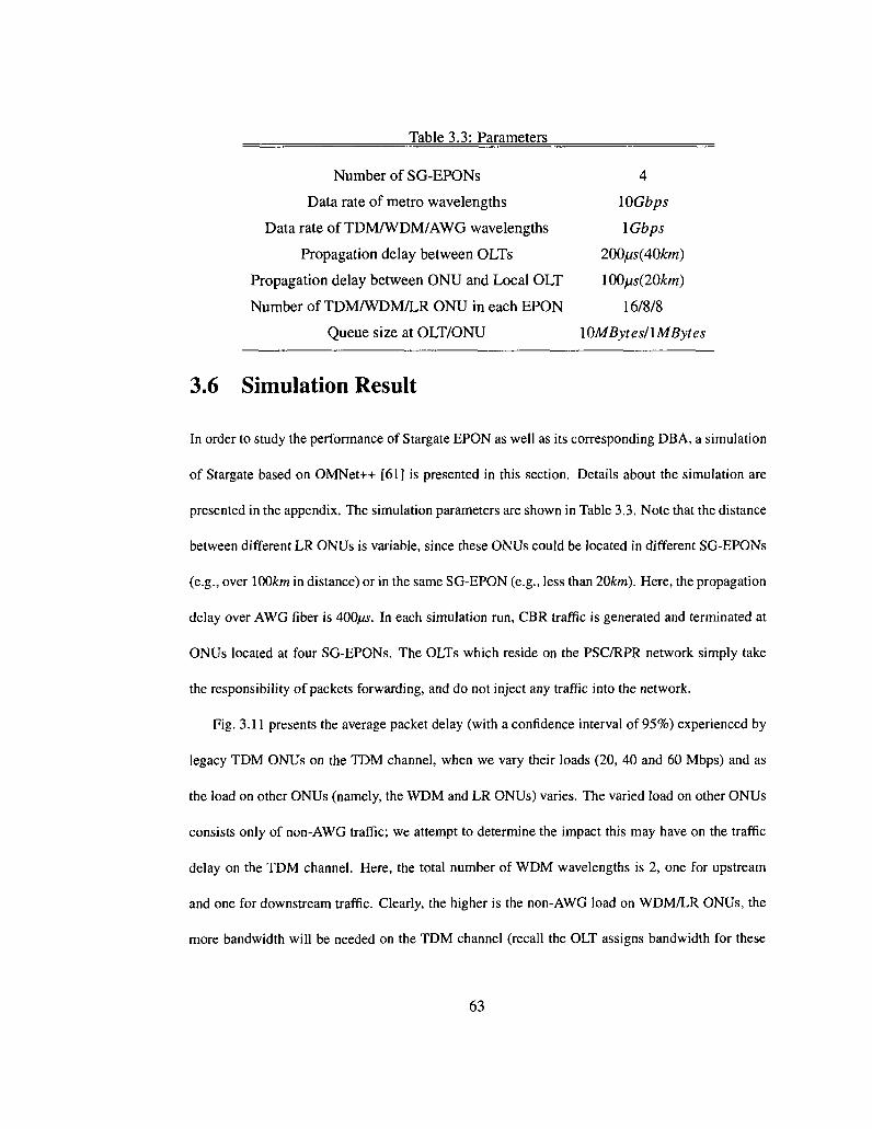
Table 3.3: Parameters
Number of SG-EPONs 4
Data rate of metro wavelengths 10Gbps
Data rate of TDM/WDM/AWG wavelengths 1 Gbps
Propagation delay between OLTs 200ps(40km)
Propagation delay between ONU and Local OLT 100/js(20km)
Number of TDM/WDM/LR ONU in each EPON 16/8/8
Queue size at OLT/ONU lOMBytesllMBytes
3.6 Simulation Result
In order to study the performance of Stargate EPON as well as its corresponding DBA, a simulation
of Stargate based on OMNet++ [61] is presented in this section. Details about the simulation are
presented in the appendix. The simulation parameters are shown in Table 3.3. Note that the distance
between different LR ONUs is variable, since these ONUs could be located in different SG-EPONs
(e.g., over 100km in distance) or in the same SG-EPON (e.g., less than 20km). Here, the propagation
delay over AWG fiber is 400/w. In each simulation run, CBR traffic is generated and terminated at
ONUs located at four SG-EPONs. The OLTs which reside on the PSC/RPR network simply take
the responsibility of packets forwarding, and do not inject any traffic into the network.
Fig. 3.11 presents the average packet delay (with a confidence interval of 95%) experienced by
legacy TDM ONUs on the TDM channel, when we vary their loads (20, 40 and 60 Mbps) and as
the load on other ONUs (namely, the WDM and LR ONUs) varies. The varied load on other ONUs
consists only of non-AWG traffic; we attempt to determine the impact this may have on the traffic
delay on the TDM channel. Here, the total number of WDM wavelengths is 2, one for upstream
and one for downstream traffic. Clearly, the higher is the non-AWG load on WDM/LR ONUs, the
more bandwidth will be needed on the TDM channel (recall the OLT assigns bandwidth for these
63

1000 r
100 r
Q o
-+-Load = 20Mbps — I — Load = 40Mbps X Load = 60Mbps —&~
0 1 2 3 4 5
non-AWG Traffic Load at WDM/LR ONUs (in Gbps)
Figure 3.11: TDM ONU Traffic Delay (W = 2, D = 1) 1000
Q o
E -
Load = 40Mbps X Load = 60Mbps — 0 —
0 1 2 3 4 5
non-AWG Traffic Load at WDM/LR ONUs (in Gbps)
Figure 3.12: TDM ONU Traffic Delay (W = 4,D = 2)
ONUs on the TDM channel as well) and that will affect the delay experienced by TDM ONUs.
First, we observe from the figure that as the load on TDM ONUs increases (e.g., from 20 Mbps to
60Mbps), the delay increases substantially. This is due to the fact that at lower loads, the assigned
transmission window is sufficient to carry the incoming traffic and the cycle duration is shorter (than
2ms), hence the TDM channel delay is low. As the load increases, the length of the scheduling cycle
increases and the size of the assigned window may not be sufficient to transmit all packets in the
buffer. Those packets that cannot be transmitted in this current cycle will be buffered until the next
cycle (or more) and hence the delay will increase.
64
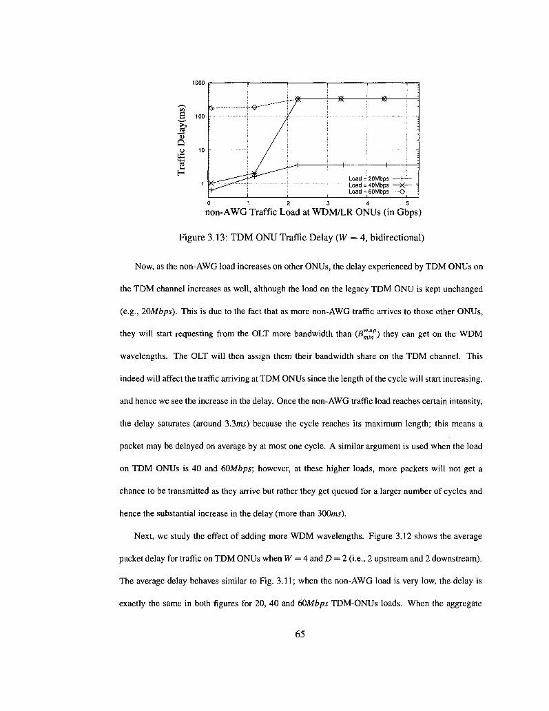
1000
v§, 10°
13 Q o 10
2 H
1
0 1 2 3 4 5
non-AWG Traffic Load at WDM/LR ONUs (in Gbps)
Figure 3.13: TDM ONU Traffic Delay (W = 4, bidirectional)
Now, as the non-AWG load increases on other ONUs, the delay experienced by TDM ONUs on
the TDM channel increases as well, although the load on the legacy TDM ONU is kept unchanged
(e.g., 20Mbps). This is due to the fact that as more non-AWG traffic arrives to those other ONUs,
they will start requesting from the OLT more bandwidth than (B^"np) they can get on the WDM
wavelengths. The OLT will then assign them their bandwidth share on the TDM channel. This
indeed will affect the traffic arriving at TDM ONUs since the length of the cycle will start increasing,
and hence we see the increase in the delay. Once the non-AWG traffic load reaches certain intensity,
the delay saturates (around 3.3ms) because the cycle reaches its maximum length; this means a
packet may be delayed on average by at most one cycle. A similar argument is used when the load
on TDM ONUs is 40 and 60Mbps; however, at these higher loads, more packets will not get a
chance to be transmitted as they arrive but rather they get queued for a larger number of cycles and
hence the substantial increase in the delay (more than 300ms).
Next, we study the effect of adding more WDM wavelengths. Figure 3.12 shows the average
packet delay for traffic on TDM ONUs when W = 4 and D = 2 (i.e., 2 upstream and 2 downstream).
The average delay behaves similar to Fig. 3.11; when the non-AWG load is very low, the delay is
exactly the same in both figures for 20, 40 and 60Mbps TDM-ONUs loads. When the aggregate
65
Load = 20Mbps — I — Load = 40Mbps X Load = 60Mbps —O—

g 100
~>^ J3 "u Q
£ 2 H
1
0 1 2 3 4 5
non-AWG Traffic Load at WDM/LR ONUs (in Gbps)
Figure 3.14: WDM ONU Traffic Delay
non-AWG load increases (e.g., l.lGbps), the delay starts to show some differences. For example,
when the TDM-ONU load is 40Mbps, the delay is close to 1.4ms, as opposed to 280ms for the
same load in Fig. 3.11. This is because adding more WDM wavelengths will increase the minimum
bandwidth guaranteed (B^^f) non TDM ONUs can receive on these WDM channels. Hence, less
non-AWG traffic will overflow to the TDM channel and that will also result in shorter cycle lengths
(as opposed to Fig. 3.11) and hence lower delays. As the non-AWG load continues to increase
(> 2Gbps), the cycle length reaches its maximum and the average delay saturates (both WDM
channels and the TDM channel are all saturated) to the same values observed in Fig. 3.11.
Finally, Fig. 3.13 shows the average delay when bidirectional transmission is used on all wave
lengths (W = 4). Here, the round trip time (RTT) delay (close to 0.2ms) between each upstream and
downstream transmission window degrades the performance of WDM/LR ONU on WDM chan
nels; as we explained earlier, the ONU (in receiving mode) has to wait for this RTT after it sends
its upstream data (recall one RSOA per ONU). Since these ONUs are allocated less resources on
the WDM channels, they will request additional bandwidth on the TDM channel which will clearly
increase the cycle length and affect the TDM-ONU traffic delay (packets at TDM ONUs will be
buffered for longer time before being transmitted).
66
W=2, D=1 1 W=4, D=2 X
W=4, bidirectional -<>—

1000
v§, 100
Q
0 1 2 3 4 5 6 7 8 9
AWG Traffic Load at LR ONUs (in Gbps)
Figure 3.15: LR ONU AWG Traffic Delay
Fig. 3.14 shows the non-AWG traffic delay of WDM ONUs as the non-AWG traffic load varies.
The traffic load of each TDM ONU is fixed to 40Mbps. As expected, the delay increases as the
load increases with smaller delays obtained when the number of used wavelengths increases. For
example, when the load is close to 2.2Gbps, the delay reduces from \04ms (W = 2,D = 1) to 55ms
(W = 4,D = 2). Notice that the network saturates at higher traffic loads (close to 3Gbps) in the
experiment corresponding to W — 4 and D = 2, which is almost 1.5 times that of W = 2 and D = 1
(between \.2Gbps and 2Gbps).
The AWG traffic delay is depicted in Fig. 3.15 as we vary the AWG load intensity (4 AWG
wavelengths in total). Since the number of AWG wavelengths is fixed (FSR=1), we choose to
change the number of LR ONUs (8, 12 and 20) in the SG-EPON in order to observe the variation
of AWG traffic delay. Clearly, higher traffic delays occur at larger number of LR ONUs since more
ONUs are sharing the same amount of bandwidth resources. We also observe that the throughput
achieved per each LR-ONU is close to 3&0Mbps {260Mbps and 150Mbps) when there are 8 LR
ONUs (12 and 20) in the network. In comparison with WDM ONUs (e.g., when W=4, D=2, the
throughput per ONU is close to \50Mbps), we notice the benefit we achieve from upgrading to LR
ONUs wherein much higher throughput (e.g., 380Mbps) can be obtained with similar traffic delays.
67
8 LR ONUS 12 LR ONUs 20 LR ONUS — O —
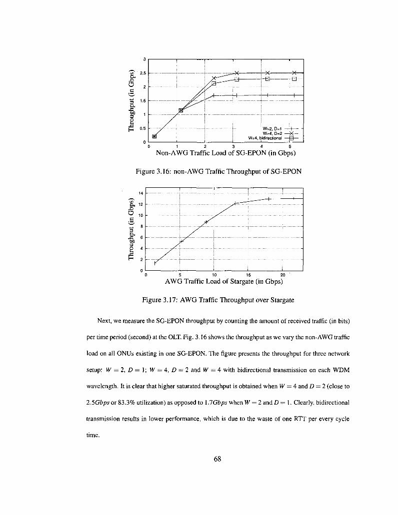
a, X>
O
3
s H
1.5 -
0.5 W=2, D=1 1— W=4, D=2 —-X-
W=4, bidirectional — B -
0 1 2 3 4 5
Non-AWG Traffic Load of SG-EPON (in Gbps)
Figure 3.16: non-AWG Traffic Throughput of SG-EPON
5 10 15 20
AWG Traffic Load of Stargate (in Gbps)
Figure 3.17: AWG Traffic Throughput over Stargate
Next, we measure the SG-EPON throughput by counting the amount of received traffic (in bits)
per time period (second) at the OLT. Fig. 3.16 shows the throughput as we vary the non-AWG traffic
load on all ONUs existing in one SG-EPON. The figure presents the throughput for three network
setup: W = 2, D = I; W = 4, D — 2 and W = 4 with bidirectional transmission on each WDM
wavelength. It is clear that higher saturated throughput is obtained when W = 4 and D = 2 (close to
2.5Gbps or 83.3% utilization) as opposed to X.lGbps when W = 2 and D = 1. Clearly, bidirectional
transmission results in lower performance, which is due to the waste of one RTT per every cycle
time.
68
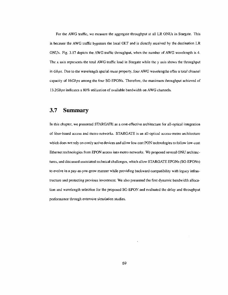
For the AWG traffic, we measure the aggregate throughput at all LR ONUs in Stargate. This
is because the AWG traffic bypasses the local OLT and is directly received by the destination LR
ONUs. Fig. 3.17 depicts the AWG traffic throughput, when the number of AWG wavelength is 4.
The x axis represents the total AWG traffic load in Stargate while the y axis shows the throughput
in Gbps. Due to the wavelength spatial reuse property, four AWG wavelengths offer a total channel
capacity of 16Gbps among the four SG-EPONs. Therefore, the maximum throughput achieved of
\3.2Gbps indicates a 80% utilization of available bandwidth on AWG channels.
3.7 Summary
In this chapter, we presented STARGATE as a cost-effective architecture for all-optical integration
of fiber-based access and metro networks. STARGATE is an all-optical access-metro architecture
which does not rely on costly active devices and allow low cost PON technologies to follow low-cost
Ethernet technologies from EPON access into metro networks. We proposed several ONU architec
tures, and discussed associated technical challenges, which allow STARGATE EPONs (SG-EPONs)
to evolve in a pay-as-you-grow manner while providing backward compatibility with legacy infras
tructure and protecting previous investment. We also presented the first dynamic bandwidth alloca
tion and wavelength selection for the proposed SG-EPON and evaluated the delay and throughput
performance through extensive simulation studies.
69

Chapter 4
Transmission Scheduling
4.1 Introduction
In this chapter we show that a straightforward transmission scheduling yields periods of idle gaps
on the transmission channels and hence could result in poor resource utilization. We suppose that
grant sizing is already predetermined using some existing method and hence we focus on grant
scheduling for multichannel SG-EPON networks. We assume a scheduling theoretic approach for
solving the grant scheduling problem; we also consider an offline scheduling method wherein the
OLT has complete information about the bandwidth requirements of the ONUs, through the Multi-
Point Control Protocol (MPCP) [39]. We show that the transmission scheduling can be effectively
formulated as an Open Shop (OS) scheduling problem and we model the joint problem of scheduling
and wavelength allocation as a Mixed Integer Linear Programming (MILP) problem. Since the
problem is shown to be NP-hard, when the number of transmission channels is more than two, an
approximate method based on Tabu Search meta-heuristic is presented for efficiently solving the
scheduling problem.
70

This chapter is organized as follows: the related work is presented in Section 4.2. Section
4.3 motivates the work through an illustrative example and we detail out the mathematical model
in Section 4.4. The approximate technique based on Tabu search is presented in Section 4.5 and
we present the numerical results for performance evaluation in Section 4.6. Finally, we present
simulation results in Section 4.7 and we conclude in Section 4.8.
4.2 Related Work
The problem of Dynamic Wavelength and Bandwidth Allocation in multichannel EPON networks
consists of two subproblems, namely, grant sizing and grant scheduling [43]. Determining how
much bandwidth each ONU can be allocated is referred to as the grant sizing (or bandwidth alloca
tion) problem and various efficient dynamic bandwidth allocation (DBA) algorithms have been pro
posed over the past few years. Of particular interest, a polling scheme IPACT (Interleaved Polling
with Adaptive Cycle Time) where multiple polling requests are overlapped in time is presented
in [60] for single channel EPON. The authors suggested to limit the maximum transmission size
allocated per ONU to prevent some ONUs from monopolizing the channel; they defined a max
imum transmission window size and presented several schemes for limited bandwidth allocation.
IPACT has been extended for multichannel networks; the authors of [40] presented WDM IPACT-
ST, where ST refers to single polling table. Each ONU is assigned bandwidth or a transmission
window on the first available wavelength and the authors have assumed that all ONUs support
all upstream wavelengths. Another WDM extension for IPACT is presented in [46] where differ
ing ONU architectures are presented and where an ONU's transmission is scheduled on the next
supported wavelength. The authors of [48] presented several dynamic wavelength and bandwidth
71
allocation (DWBA) algorithms in a WDM-PON network consisting of ONUs with fixed and tun
able wavelength transmission capabilities. In one approach, grant sizing is done using a DBA
algorithm when ALL ONUs have REPORTed their bandwidth requirements to the OLT and wave
length allocation (or grant scheduling) occurs on the first available wavelength. Another approach
is also proposed and consists of scheduling immediately those under loaded ONUs (always using
first available wavelength) while those highly loaded ONUs are deferred until all REPORT mes
sages have arrived. This enables the OLT to distribute the excessive bandwidth fairly among those
ONUs. More recently the authors of [62] presented a control plane for next generation multichan
nel access networks and provided a flexible upstream wavelength allocation which is based on a
hybrid TDM A-WDM A access protocol. The authors introduced the concept of macroscopic and
microscopic timescale traffic assignment and presented a mathematical model based on ILP and an
approximate technique based on Tabu search.
The only work which we are aware of that considers the problem of efficient grant scheduling in a
multichannel EPON networks is presented in [43] in a Just-in-Time (JIT) Scheduling framework.
The authors noted that the choice of scheduling framework has typically the largest impact on av
erage queuing delays and achievable channel utilization. They assumed that grant sizing is done
using some existing technique [38] [57] and focused on scheduling these grants for efficient up
stream transmission. To achieve their objective, a layered scheduling approach is introduced which
consists of a scheduling framework and a scheduling policy. The scheduling framework is a logisti
cal one that determines when the OLT makes scheduling decisions. An online scheduling refers to
when the OLT produces a schedule as soon as any ONU REPORT is received without waiting for
REPORT messages from other ONUs; in the offline scheduling, the OLT waits for all REPORT mes
sages to arrive before making schedule decisions. The former approach avoids wasted bandwidth
on the channel by not keeping any channel idle while there is an ONU waiting to be scheduled. The
72
latter enables the OLT to make better grant sizing and scheduling decisions since it has complete
information about ONUs bandwidth requirements. This scheduling framework can be viewed as a
continuum between the extremes of online and offline scheduling. The online JIT proposed in [43]
defines a scheduling pool where ONUs are added to this pool and those in the pool are scheduled
as soon as a wavelength becomes available. A scheduling policy, on the other hand, is a method
for the OLT to produce a schedule. The authors of [43] observed that each ONU can be viewed
as a job, its grant size defines the processing time, and the channels used for transmission on the
EPON represent machines. Therefore, the problem reduces to scheduling a set of jobs, with specific
processing times, to be executed on a set of machines with respect to some optimization criterion.
Various underlying scheduling policies or their combinations are examined, such as the parallel ma-
chine(PM) model [63], Next Available Supported Channel(NASC), Least Flexible Job First(LFJ),
Shortest Processing Time First(SPT) and Weighted Bipartite Matching(WBM) formulation. In the
PM model, the multichannel EPON grant scheduling problem is formulated as P|M,-|£,-C,-, where
P denotes the identical parallel channels; M, is the set of channels that ONUj can transmit on; C,
denotes the time at which the transmission for ONUi is complete. The optimization objective is to
minimize the queuing delay experienced by frames in transit across the EPON and to increase the
achievable resources utilization.
4.3 Motivation and Problem Statement
Our objective in designing an efficient grant scheduler at the OLT is to increase the achievable
resource utilization and hence lower queuing delays experienced by frames in transit across the
access network. As mentioned in section 3.3, a cost effective design approach has been adopted for
SG-EPON; instead of equipping each ONU (being WDM or LR) with an array of fixed-tuned or
73

t2
© . © , , a , ©_
X
to
1 t, !
1
Xa,i
ONU4
© ONU5 |
© ONU1
t3
©
I • * -
ONU1
© ONU2
A,
ONU3
I
1 _ ONUS
~1 l~~ © *' ONU3 |
© | ONU1
©
I
ONU3
A,
|
I
ONU5 |
|
© ONU2 I ,
• •* •
A
Figure 4.18: Illustration of OSP using a Disjunctive Graph
tunable transceivers, a reflective semiconductor optical amplifier is used for remote modulation of
upstream data. In other words, the ONU uses one RSOA to either transmit or receive data on either
WDM (for WDM- and LR-ONUs) or AWG (for LR ONUs) wavelengths. Further, an ONU could
either be in a receiving mode or a transmitting mode (the half duplex transmission property). Though
it is cost effective, the use of one RSOA per ONU to modulate the upstream transmission (or receive
the downstream data on a WDM channel), together with the fact that an ONU may transmit/receive
on multiple channels during a scheduling period, may lead to an efficiency problem if the OUT does
not produce an efficient schedule for upstream/downstream transmissions.
For illustration, we consider the scheduling problem illustrated in Figure 4.18 where an offline
scheduling framework is used along with Next Available Supported Channel (NASC) scheduling
policy. Three long reach ONUs (CW£/i,2,3) and two WDM ONUs {ONU^5) are considered for
scheduling in a network with one upstream and one downstream WDM wavelength (kw,u, Aw,A two
long reach wavelengths (A,a,i» Xaj). We assume grant sizing has been done through some existing
scheme [60] following the bandwidth requests from the ONUs. As shown in Figure 4.18, to, t\, H,
and t-i designate the times wavelengths 'KWM, Xa>i, A^d, and Xa,2 become available respectively. The
numbers in the circles, shown in the figure, designate the order considered by the OLT to schedule
the ONUs on the corresponding channels. Using the NASC scheduling policy, it can be easily
74
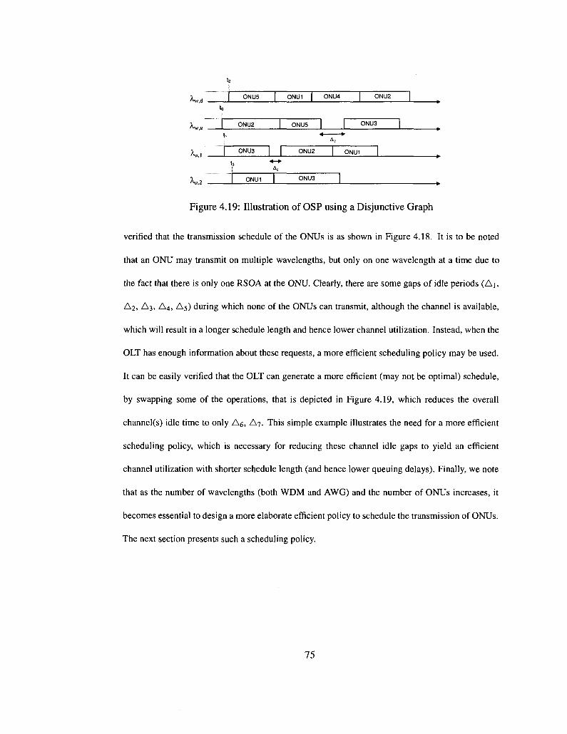
to
K „ 1,
|
ONU5
ONU2
ONU3
*»
^•a.2 ... ONU1
I
I | •*-*•
I
ONU1 |
ONU5
ONU2
ONU3
ONU4
i r~ A,
1 ONU1
I
ONU2 |
ONU3 |
~1 *
Figure 4.19: Illustration of OSP using a Disjunctive Graph
verified that the transmission schedule of the ONUs is as shown in Figure 4.18. It is to be noted
that an ONU may transmit on multiple wavelengths, but only on one wavelength at a time due to
the fact that there is only one RSOA at the ONU. Clearly, there are some gaps of idle periods (Ai,
A2, A3, A4, A5) during which none of the ONUs can transmit, although the channel is available,
which will result in a longer schedule length and hence lower channel utilization. Instead, when the
OLT has enough information about these requests, a more efficient scheduling policy may be used.
It can be easily verified that the OLT can generate a more efficient (may not be optimal) schedule,
by swapping some of the operations, that is depicted in Figure 4.19, which reduces the overall
channel(s) idle time to only A6, A7. This simple example illustrates the need for a more efficient
scheduling policy, which is necessary for reducing these channel idle gaps to yield an efficient
channel utilization with shorter schedule length (and hence lower queuing delays). Finally, we note
that as the number of wavelengths (both WDM and AWG) and the number of ONUs increases, it
becomes essential to design a more elaborate efficient policy to schedule the transmission of ONUs.
The next section presents such a scheduling policy.
75

4.4 An Efficient Scheduling Policy
4.4.1 Preliminaries
The previous section has demonstrated that, under the considered network architecture, the selection
of the scheduling policy is indispensable for achieving the desired objectives of superior system uti
lization and lower queuing delays. Similar to the JIT scheduling policy [43], our scheduling problem
can be formulated using scheduling theory [63]. Scheduling theory is concerned with scheduling
a set of jobs with specific processing times to be executed on a set of machines as efficiently as
possible with respect to an optimization criterion. In [43], the authors viewed each ONU as repre
senting a job, its allocated grant size defines the processing time of the job, and the channels used
for transmission on the multichannel EPON represent the machines. In scheduling terminology,
the triple oc|P|y denotes a scheduling problem where a describes the machine environment (e.g.,
single machine, parallel machines, flow shop, etc.), (3 provides details of processing characteristics
and constraints, and y describes the objective to be minimized. Since in [43] all the channels are
identical with the same speed/bandwidth, the scheduling problem has been modeled as identical
machines in parallel. In particular, denote by P the number of channels in the network, A/; the
machine (channel) eligibility constraint which refers to the set of channels a job (or ONU) i can be
executed (transmit) on1, and C, which refers to the time a job (ONU's transmission);' is complete;
accordingly, the scheduling problem is defined as P\Mi\Y.iQ where the objective is to minimize
the un-weighted sum of the completion times [43], Note that in the multichannel EPON system
of [43], each ONU may transmit on only one channel per scheduling period, and may support a
subset of (or all) wavelengths. In SG-EPON, however, there are different requirements that make
the parallel machine model unsuitable. As mentioned in section 3.3, there are two types of ONUs
'This processing constraint is needed if each ONU has its own subset of channels it can transmit on.
76

(LR- and WDM-ONUs) some of them (e.g., WDM ONUs) may be scheduled only on one, but any,
wavelength in AWDM and others (e.g., LR ONUs) on any wavelength in AWDM^^-AWG- Further, a
LR ONU may be scheduled on more than one wavelength during the same scheduling period for
reaching different (LR) destinations. Additionally, any ONU may be receiving downstream and
sending upstream traffic in the same scheduling period. This accordingly requires a different, more
appropriate, scheduling discipline.
4.4.2 The Open Shop Problem, OSP
The open shop refers to a problem where there are n jobs and m machines, each job has to be
processed on each one of the m machines. The OSP, with the objective of optimizing the maxi
mum completion time, is denoted as Om\\Cmax [63] and can be described as follows. Given n jobs
{//|1 < j < n} and m machines {Af,-|l <i<m} where each job Jj is subdivided into m operations
{Oij\l < i < m}, then operation Ojj must be performed on machine M, and requires a processing
time ptj. Note that some of the processing times may be zero; further, there are no restrictions
with regard to the routing of each job through the machine environment. Here, a route for a job
determines the sequence of machines the job is executed/processed on. In the open shop, the sched
uler is allowed to determine a route for each job, and different jobs may have different routes. The
Om | \Cmax refers to an open shop where preemption is not allowed; preemption implies that it is not
necessary to keep a job on a machine, once started, until its completion. The scheduler is allowed to
interrupt the processing of a job (preempt) at any time and put a different job on the same machine
instead. When this preempted job is put back on this machine, it only needs the machine for its
remaining processing time. The objective of Om\\Cmax is to minimize the makespan, i.e., the total
time needed to complete all the jobs. Note that, in OSP each job Jj can be processed on only one
machine at the same time and each machine M,- can process only one job at a time.
77
In SG-EPON, each ONUj is viewed as a job Jj which needs to be executed; a transmission win
dow (or grant) Wy assigned for ONUj for transmission on wavelength X, can be interpreted as
an operation 0, ; for job Jj on machine M, and each ONU may have a list of transmission grants
{Wij\\ < i < m). The length of a transmission window f,-y- can be viewed as the processing time
(pij) of each operation (the terms operation, transmission grant or transmission window will be
used interchangeably). If an ONU either cannot transmit or is not scheduled on a wavelength, then
tij = pij = 0. Each wavelength A.,- is considered as a machine M; and all machines have the same
speed. Consequently, scheduling transmission grants in a multichannel SG-EPON can be formu
lated using the open shop (without preemptions) model, where the objective is to minimize the
length of the scheduling period (or the maximum completion time, Cmax).
A rule referred to as Longest Alternate Processing Time first (JAPT) yields an optimal schedule for
<?2||Cmai: when there are only 2 channels (machines) and n ONUs (jobs). The LAPT rule can be ex
plained as follows: whenever a channel is available, start processing among the ONUs that have not
yet received processing on either channel, the one with the longest processing time (or transmission
window) on the other channel. According to this rule, whenever a channel becomes available, those
ONUs that have completed their transmission on the other channel have the lowest priority on the
channel just freed. It can be shown that LAPT results in an optimal schedule for O2I |Cm(U with [63]:
n n
Cmax = max( max {t\j,t2j), Y hj, Y t2j) (11) jei...,» j=i _,fi
Indeed, the LAPT rule may be regarded as a special case of a more general rule that can be
applied to open shops with more than two machines; this rule is referred to as the Longest Total
Remaining Processing on Other Machines first rule. Unlike LAPT, which can be solved in linear
time, the more general rule does not always result in an optimal schedule.
78
Theorem 4.4.1. The problem Om\\Cmax is NP-hard when m>3.
Proof. The proof, when m = 3, can be found in [63] and [64]. •
Theorem 4.4.2. There exists an immediate lower bound, LB, for Om\\Cmax [64]. This lower bound
is defined as:
n m LB = max{ max { £ / ? , , } , max {£/?, ,}} (12)
l<i<m Tj7| \<]<n JT,
Proof The proof is straight forward. Since a channel cannot process two transmission grants si
multaneously, at least Y!)=\Pij t i m e is needed by each channel A,, to perform all its operations.
Analogously, since two transmission grants of the same ONU cannot be processed at the same time
(the single RSOA constraint), at least Y!jL\ Pij time is needed to complete all operations (grants) of
the same ONU. The maximum of these quantities is clearly a lower bound on the optimal solution
OfOnWCmax. U
4.4.3 Mathematical formulation
We consider a multichannel SG-EPON network (we refer to it as the home network2) with N ONUs;
two types of ONUs are considered, LR-ONUs and WDM ONUs. The instantaneous data rate for a
WDM ONU j (in the home network) is R"j{bps) for upstream and RdAbps) for downstream demands.
A WDM ONU can transmit on any wavelength Xi € A|J, (U is the total number of upstream WDM
channels) and receive on any wavelength A,,- £ A , (D is the total number of downstream WDM
channels) where AJJ, and A , are the set of upstream and downstream WDM channels. Note that a
WDM ONU can either transmit or receive at the same time, since the ONU is equipped with one
RSOA. Further, due to that same constraint, a WDM ONU can transmit on only one channel at a
time and two ONUs cannot transmit/receive on the same channel concurrently (wavelength conflict
2The home network refers to the network where we perform the scheduling.
79

constraints). In addition, we assume all (up/down) traffic of a WDM ONU is transmitted on only
one (up/down) WDM channel (i.e., a flow should not be bifurcated on multiple channels) and the
load per such ONU does not exceed the capacity of one wavelength.
Similar to WDM ONUs, a LR-ONU has the same bandwidth requirement and transmission/reception
capabilities; further, a LR ONU may transmit/receive to other LR ONUs, located either on the same
(i.e., the home SG-EPON) or on distant long reach SG-EPONs through the AWG network, as shown
in Figure3.7. Let M denote the number of SG-EPONs connected through Stargate and let / denote
the free spectral range (FSR) of the AWG router used to interconnect these LR-EPONs [1], Hence,
a subset of Long Reach AWG channels (A™, | A™ | = / ) can be used to interconnect LR ONUs in the
home network to other LR ONUs on another distant SG-EPON m, m = 1, ..,M; Aa (A0 = Um A«)
is then the set of all AWG wavelengths. Denote by I^'m(bps) the upstream instantaneous data rate
of a LR ONU j (in the home network) to another LR ONU in SG-EPON m. Since a LR ONU
receives all downstream AWG channels (Figure3.7), it either receives all the frames if it is the desti
nation or ignore them, otherwise. Note that, as explained earlier, a LR ONU does not use the RSOA
for receiving the downstream traffic (coming from distant SG-EPONs through the AWG network),
making the scheduling problem less complicated. Similar to a WDM ONU, a LR ONU can trans
mit on only one wavelength A,,- € AJJ, or A.,- € Aa or receive on A,,- G AjJ, at a time. Additionally, two
different LR ONUs (in the same home network) cannot transmit on the same channel concurrently
(the wavelength conflict constraints).
We assume the OLT, through the MPCP protocol [39], knows the bandwidth requirements (we as
sume, without loss of generality, that ONUs have some demands which may exist for sometime;
e.g., storage and grid applications, TV broadcast, video on demand, etc.) of all ONUs in its home
network. We also assume that, given the bandwidth requests from the ONUs, grant sizing is done
through some existing algorithm, e.g., [60] [57] [65]. Denote by w" (wj) the bandwidth allocated
80
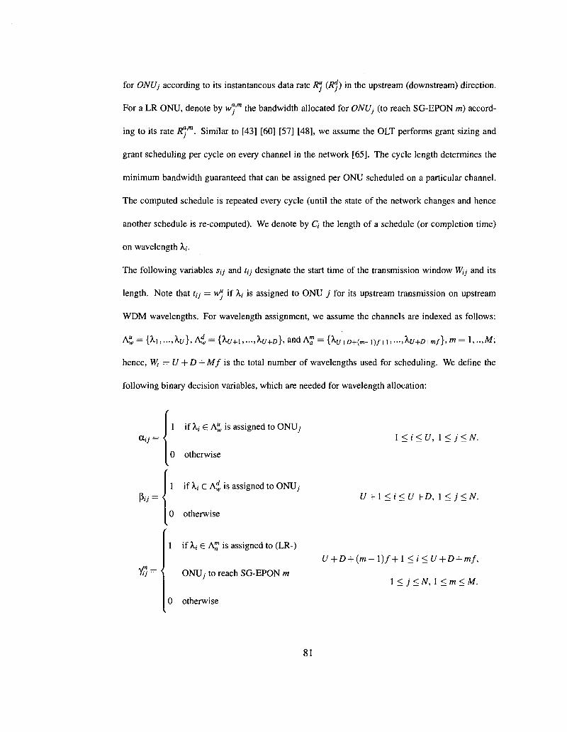
for ONUj according to its instantaneous data rate R": (RJ) in the upstream (downstream) direction.
For a LR ONU, denote by w"'"1 the bandwidth allocated for ONUj (to reach SG-EPON m) accord
ing to its rate R^'1". Similar to [43] [60] [57] [48], we assume the OLT performs grant sizing and
grant scheduling per cycle on every channel in the network [65]. The cycle length determines the
minimum bandwidth guaranteed that can be assigned per ONU scheduled on a particular channel.
The computed schedule is repeated every cycle (until the state of the network changes and hence
another schedule is re-computed). We denote by C, the length of a schedule (or completion time)
on wavelength A,,-.
The following variables sy and f,y designate the start time of the transmission window W,;- and its
length. Note that ?,y = w": if Xj is assigned to ONU j for its upstream transmission on upstream
WDM wavelengths. For wavelength assignment, we assume the channels are indexed as follows:
K = {h,—,hj}, K> = {A*/+I,...,A*/+D}> and A™ = {Xu+D+(m_^f+u...,Xu+D+mf}, m = l,..,Af;
hence, Wt = U + D + Mf is the total number of wavelengths used for scheduling. We define the
following binary decision variables, which are needed for wavelength allocation:
a,; = <
Py = {
tj={
1 if Xi £ AJJ, is assigned to ONU;
0 otherwise
1 if Xi £ hi is assigned to ONU,-
0 otherwise
1 if Xi e A^ is assigned to (LR-)
ONU; to reach SG-EPON m
0 otherwise
1 < i < U, \<j<N.
U+\<i<U + D, \<j<N.
U + D+{m-l)f+\ <i<U + D + mf,
\<j<N,\<m<M.
81
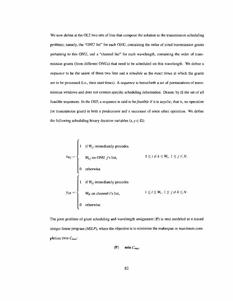
We now define at the OUT two sets of lists that compose the solution to the transmission scheduling
problem; namely, the "ONU list" for each ONU, containing the order of sized transmission grants
pertaining to this ONU, and a "channel list" for each wavelength, containing the order of trans
mission grants (from different ONUs) that need to be scheduled on this wavelength. We define a
sequence to be the union of these two lists and a schedule as the exact times at which the grants
are to be processed (i.e., their start times). A sequence is henceforth a set of permutations of trans
mission windows and does not contain specific scheduling information. Denote by Q. the set of all
feasible sequences. In the OSP, a sequence is said to be feasible if it is acyclic; that is, no operation
(or transmission grant) is both a predecessor and a successor of some other operation. We define
the following scheduling binary decision variables (x,y £ Q.):
Xikj = <
ytjh = <
1 if W{j immediately precedes
Wkj on ONU y"s list,
0 otherwise
1 if Wtj immediately precedes
Wih on channel I'S list,
0 otherwise
\<i^k<W„ l<j<N.
1 <i<W,, \<j^h<N.
The joint problem of grant scheduling and wavelength assignment (P) is next modeled as a mixed
integer linear program (MILP), where the objective is to minimize the makespan or maximum com
pletion time Cmax'-
(P) min Cmax
82
Where
Cmax — mox\<i<w, {Q}> a nd Q is the length of a schedule on wavelength Xj. Expression (13)
forces the maximum completion time to be no less than the transmission finishing time of any ONU
on any wavelength. Cmax - su > tij, \<i<W„l<j<N, (13)
Constraints (14) indicate that if Wkj is scheduled immediately after Wij on ONU j's list, then Wkj
can only start at time Skj when Wij finishes. In other words, the scheduled grants on ONU j's list
can not overlap with each other.
Skj-Sij>tij-T(\-Xikj), l<i^k<W„]<j<N, (14)
Sih-Sij > tij ~ T(l -yiJh), \<i<Wt,\<j^h<N, (15)
where T is a very large positive integer. For example, when W^ immediately precedes W^ on
ONUj's list, then x&j — 1, and as a result (14) guarantees that s^j > sy + Uj. Constraints (15)
indicate that if W^ is scheduled immediately after Wij on channel X,'s list, then W,/, can only start at
time tu, when Wtj finishes. In other words, the scheduled grants on X,-'s list can not overlap with each
other. Constraints (16) and (17) imply that, in the set AJJ, (or A^), at most one wavelength can be
assigned to ONU j in each scheduling round. Constraints (18) set an upper bound on the number
of AWG wavelengths for each LR ONU j such that at most one wavelength in each set A™ can be
assigned to it. u
£(Xy=fl ; , l<j<N, (16) i=\
where aj = 1 if w" ^ 0 and a7- = 0 otherwise.
U+D £ fiij = bj, \<j<N, (17)
i=U+\
83
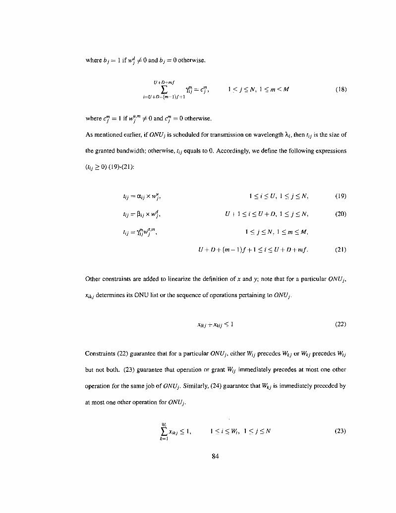
where bj = 1 if wj =/= 0 and bj = 0 otherwise.
U+D+mf
L tj = c"j, \<j<N,\<m<M (18) i=U+D+(m-l)f+\
where cj = 1 if w°'m / 0 and c 1 = 0 otherwise.
As mentioned earlier, if ONUj is scheduled for transmission on wavelength Xt, then r,y- is the size of
the granted bandwidth; otherwise, tjj equals to 0. Accordingly, we define the following expressions
(tu > 0) (19)-(21):
1 <i<U, \<j<N, (19)
U+\ <i<U + D, 1 <j<N, (20)
l<j<N, \<m<M,
U + D+{m-\)f+\<i<U + D + mf. (21)
Other constraints are added to linearize the definition of x and y\ note that for a particular ONUj,
Xfcj determines its ONU list or the sequence of operations pertaining to ONUj.
Xikj+xkij<\ (22)
Constraints (22) guarantee that for a particular ONUj, either Wjj precedes W^j or Wkj precedes Wjj
but not both. (23) guarantee that operation or grant W(j immediately precedes at most one other
operation for the same job of ONUj. Similarly, (24) guarantee that W^j is immediately preceded by
at most one other operation for ONUj.
w, £*,*;<!, 1<«<W„ \<j<N (23)
84
tu = au x wuj,
tU = Py X Wdj,

w, £*a;<l, \<k<W„ \<j<N (24) 1=1
(25) guarantees that on ONU/s list, there are exactly W, operations/grants (Wij,i = 1,..,W,), each
of these operations/grants is immediately preceded by exactly one other grant, except the first one,
which is not preceded by any. It is to be noted that the size (or processing time) of a grant (operation)
assigned to ONUj on some wavelength could be 0 if the ONU is not scheduled for transmission on
that wavelength; however, the operation must still be included in ONU/s list.
w, w, L X > * , = W ( - 1 , l<j<N (25) i= l k=\
Finally, it can be easily seen that x„j = 0, 1 < i < Wt, 1 < j < N. In a similar manner, we
can rewrite the constraints for linearizing the definition of y; for a particular wavelength V ytjh
determines the list of operations pertaining to V s ns t- Constraints (26) guarantee on V s list, either
Wij precedes Wo, or Wo, precedes Wjj but not both. Constraints (27) ensure that if W,; immediately
precedes W,/,, then Wij cannot immediately precede any other transmission window on V s list'
Constraints (28) ensures that if Wij immediately precedes Wih, no other transmission window can
immediately precede Wih- (29) guarantee that on V s list, there are exactly N transmission windows
(Wij» j — 1,-,A0> each of these grants is immediately preceded by exactly one other grant, except
the first one, which is not preceded by any. As before, note that the size of a transmission window
assigned to some ONUj on Xi may be 0 if the ONU is not scheduled for transmission on that
wavelength; nonetheless, the operation must still be included in V s list despite the fact that its
processing time is 0.
yijh+yuij<i (26)
N
J>;*<1, l<i<W„l<j<N (27)
85

N
!>•;*< 1, l<i<W„ \<h<N (28) 7 = 1
N N
IL},i»=iV-l, l<i<W, (29) j=\h=\
It can also be easily seen that y,j;- = 0, 1 < i < Wt, 1 < j < N.
4.5 A Tabu Search Approach
In the previous section we presented a mathematical formulation for the joint grant scheduling
and wavelength assignment problem. It was also shown that OmWCmax is NP-hard for n > 3 (as
mentioned in Section 4.4.2); indeed, enumerating all the possible feasible sequences in SI makes
the problem difficult to solve for optimality in reasonable amount of time. Instead of looking for
the costly optimal solution, we now develop a heuristic method for solving the problem using a tabu
search.
4.5.1 Dispatching Rules
In this section we present some heuristic algorithms that can be used to build feasible solutions to
the OSP adapted to SG-EPON (i.e., feasible schedules for the transmission scheduling and channel
allocation problem), which are also referred to as dispatching rules [66]. These heuristics are char
acterized by different criteria used to generate a sequence, or a complete schedule. At each iteration,
they try to schedule an ONU on a wavelength "as soon as possible", i.e., beginning at the earliest
time so that it does not overlap with other already scheduled transmissions of the same ONU. Note
that, generally these rules do not yield optimal solutions except in some particular scenarios (e.g.,
LAPTfor02 | |
86
NASC
This is a simple scheduling policy that concerns scheduling ONUs on supported wavelengths (i.e.,
wavelength selection); the feasible solution is obtained by scheduling ONUs (one at a time) on each
wavelength according to the NASC (Next Available Supported Channel [43]) rule. Here, each ONU
is scheduled on its supported channel that first becomes available.
LPT
The feasible solution is obtained by scheduling ONUs on each wavelength according to the LPT
(Longest Processing Time [67]) rule; here, on each wavelength ONUs are considered in decreasing
order of assigned transmission window size.
SPT
The feasible solution is obtained by scheduling ONUs on each wavelength according to the SPT
(Shortest Processing Time [67]) rule; here, on each wavelength ONUs are considered in increasing
order of assigned transmission window size.
LRPT
The feasible solution is obtained by scheduling ONUs on each wavelength according to the LRPT
rule (Total Remaining Processing Time [63]); here, ONUs with the highest total size of unscheduled
transmission window(s) are considered first.
LTKPOM(Longest Total Remaining Processing on Other Machines first [63])
This is the more general counterpart of LAPT. Every time a wavelength is available, the ONU with
the largest total size of unscheduled transmission window on other wavelengths, among all ONUs,
87

is selected for scheduling.
Note that, the above rules (LPT, SPT, LRPT, and LTRPON) are concerned with scheduling
ONUs on a predetermined wavelength; the wavelength on which ONUs are scheduled is always
determined according to the NASC rule. A number of other dispatching rules as well as their
combinations can be found in [66].
4.5.2 Tabu Search Heuristic
The tabu search is an iterative heuristic optimization method based on local search techniques,
which starts from a feasible solution and at each iteration moves to another, possibly better, solution
trying to search unexplored regions of the solutions space and to avoid cycling. The new solution s'
selected at each iteration of the procedure is the best one belonging to a given neighborhood N(s),
of the current solution s. The neighborhood generally contains all the solutions that can be obtained
from s by means of simple modifications, or moves. A Disjunctive Graph Model is used to describe
the open shop scheduling problem while stepping throughout the neighborhood and searching for
s' [67]. The tabu search algorithm also uses a short term memory mechanism called tabu list which
stores the attributes of the most recently examined solutions, thus reducing the possibility of cycling
while searching in the solution space. In the exploration of the neighborhood of the current solution,
all the solutions whose attributes are in the tabu list (or that can be obtained from the current one
with tabu moves) are not considered. Although many other features may be added to this basic
framework in order to improve its performance, we will only elaborate on the major ones in the
following discussion; for more details the interested reader is referred to [67,68].
88
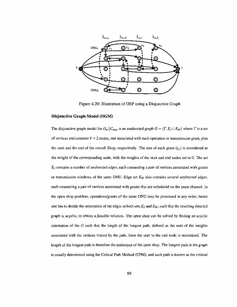
Figure 4.20: Illustration of OSP using a Disjunctive Graph
Disjunctive Graph Model (DGM)
The disjunctive graph model for Om| \Cmax is an undirected graph G = (T, EJUEM) where T is a set
of vertices and contains V + 2 nodes, one associated with each operation or transmission grant, plus
the start and the end of the overall Shop, respectively. The size of each grant (/,;) is considered as
the weight of the corresponding node, with the weights of the start and end nodes set to 0. The set
Ej contains a number of undirected edges, each connecting a pair of vertices associated with grants
or transmission windows of the same ONU. Edge set EM also contains several undirected edges,
each connecting a pair of vertices associated with grants that are scheduled on the same channel. In
the open shop problem, operations/grants of the same ONU may be processed in any order, hence
one has to decide the orientation of the edges in both sets Ej and EM, such that the resulting directed
graph is acyclic, to obtain a feasible solution. The open shop can be solved by finding an acyclic
orientation of the G such that the length of the longest path, denned as the sum of the weights
associated with the vertices visited by the path, form the start to the end node is minimized. The
length of the longest path is therefore the makespan of the open shop. The longest path in the graph
is usually determined using the Critical Path Method (CPM), and such path is known as the critical
89

•w,d *^w,u "*a,\ n*a,2
Figure 4.21: Modified Disjunctive Graph
path.
Figure 4.20 shows the representation of the feasible solution (shown in Fig.4.18), of the schedul
ing problem presented in section 4.3, using the disjunctive graph. The vertices correspond to the
different grants (of ONUs 1—>5) to be scheduled on both WDM and AWG channels and the weight
of each vertex corresponds to the length of its corresponding grant. For instance, vi in Figure 4.20
corresponds to the transmission grant of ONU1 on "Ku,w- Horizontal directed edges represent the
sequence of operations of the same ONU on different channels and vertical directed edges represent
the sequence of operations of different ONUs on the same channel. For example, a directed edge
from the start node s to V3 indicates that V3 is the first scheduled operation of ONU\ and the sequence
(route) of ONU1 's operations is < s — V3 — vi — V4 — / >. It can be easily verified that the resulting
graph is acyclic. It is to be noted that in the open shop problem, all machines are assumed to be idle
before any operation of any job is processed; in other words, all machine are idle before entering the
shop. This, however, may not necessarily be the case for scheduling transmissions in SG-EPONs.
As we can see in Figure 4.18 (and Figure 4.19), all channels have different starting times, and their
90
finish times are also different. Therefore we now modify the definition of the disjunctive graph as
follows. Let ts be the time when the OLT starts its computation for the next schedule (e.g., the time
when the OLT receives all REPORT messages from the ONUs) and r,- (f,- > ts) be the time channel
Xi is free for scheduling. We add to the disjunctive graph then dummy vertices, as many as the
number of machines or channels (i.e., W), each represent a dummy operation on the corresponding
machine. The weight of a dummy vertex (*/,•) representing an operation on A., is set to /, —ts. The
disjunctive graph is then redefined as G= (r,£yU£/w), where T contains V + 2 + W nodes; Ej has
the same definition as before, and also contains new directed edges emanating from the start node
and incident on the dummy nodes. EM maintains the same definition as before, in addition to new
directed edges emanating from each dummy node to all operations on the same channel as well as
to the terminating node. Figure 4.21 represents the modified disjunctive graph representation of the
feasible solution presented in Figure 4.18 of the scheduling problem presented in section 4.3; as can
be seen, the new graph is acyclic and using the CPM, the critical path (as well as the makespan) can
easily be determined.
Neighborhood Structures and Tabu Search
The choice of the neighborhood is one of the most critical components of the tabu search algorithm.
In our scheduling problem, the first type of move we considered is as follows: the neighborhood s' of
a current solution s is obtained by reverting the transmitting order of two or three consecutive critical
operations or grants of the same ONU, or, alternatively, by reverting the transmitting order of two
or three consecutive critical grants of different ONUs on the same wavelength. The term "critical"
here refers to these grants that are on the critical path in the disjunctive graph which corresponds to
s.
91
The second type of move considers shifting operations of the same ONU on different wave
lengths; for example, one ONU with upstream traffic may be assigned to any upstream wavelength
in A ,. Hence, operations on upstream wavelengths may be swapped from one channel to another
in the same set. Similarly, for downstream and LR traffic, one operation may be moved from one
channel to another in its corresponding eligible set (A^, A™). These type of moves will yield to a
feasible channel assignment along with a feasible sequence of operations. We note that such type of
move does not exist for the original OSP since this latter does not involve any machine assignment
and is only concerned with swapping operations on the same machine or swapping operations of
the same job.
Our tabu search algorithm consists then of performing a local search, using these above moves,
to explore new feasible solutions; it also makes use of a short term memory (tabu list) that stores
information associated with recently explored solutions in order to avoid cycling. For example, the
tabu list contains the positions of the swapped operations, and any move that schedules an operation
back to its old position is considered tabu (forbidden) [67]. Further, and similar to [67], an aspiration
criterion which allows to override the tabu status of a move is used, so that any move that yields
better improvement is considered regardless of the status of the move. Search diversification is
obtained by allowing the algorithm to make restart and random perturbations. The algorithm restarts
after executing X iterations without any improvement on the current best solution. Periodic random
perturbations are also used to enhance the diversification of the search. A perturbation is executed
every y iterations and consists of randomly selecting and executing a move from the neighborhood
regardless of its quality and status.
92
4.6 Performance Results
We implemented using C++ the tabu search procedure described above and the dispatching rules
NASC, LRPT-LPT and LTRPOM-LPT. Note that, as in [66], we implemented the LPT as a sec
ondary rule with LRTP and LTRPOM to break the tie. For LRPT-LPT and LTRPOM-LPT, we as
sume always next available supported channel for wavelength selection, and for NASC we assume
ONUs are scheduled one by one according to a predetermined order.
In our tabu search, we have used X = {50N, 100N, 15(W} and y = 50N (N is the number of
ONUs), which are the algorithm restart and perturbation parameters (see [67]). Using these param
eters, the execution of our Tabu search procedure did not exceed 6-10 minutes. Although shorter
running time is feasible, it will slightly decrease the optimality of the solution found by Tabu. We
also solved the MILP model using CPLEX 9.1.3 [69], for only small instances of the problem.
We tested our tabu algorithm for different groups of experiments, by varying the number of
ONUs as well as the number of wavelengths in each group. In the same group, we ran 5 experi
ments, randomly selecting each ONU's bandwidth requirement from 10% to 100% of its minimum
guaranteed bandwidth Bmin [65] 3 on WDM upstream/downstream and AWG wavelengths; we as
sumed a CBR traffic in all experiments. The configuration of these 5 experiments in each group is
described as follows: for experiments 1 to 4 (E\ — £4), the bandwidth requirement is set to 10%-
30%, 30%-50%, 50%-70% and 70%-100% of Bmin for each ONU on both WDM upstream and
AWG wavelengths; for the bandwidth demand on WDM downstream wavelengths, it was set to
5%-25% for each ONU in all of these four experiments, simulating a low WDM downstream traf
fic scenario. In £5, however, these values are set to 70%-100% (demand on WDM upstream and
AWG wavelengths) and 75%-95% (demand on WDM downstream wavelengths) for each ONU,
3Note that this flmln is calculated based on limited service [60]; for those ONUs requesting bandwidth larger than Bm,„, they are only granted a transmission window size equivalent to Bm,„.
93
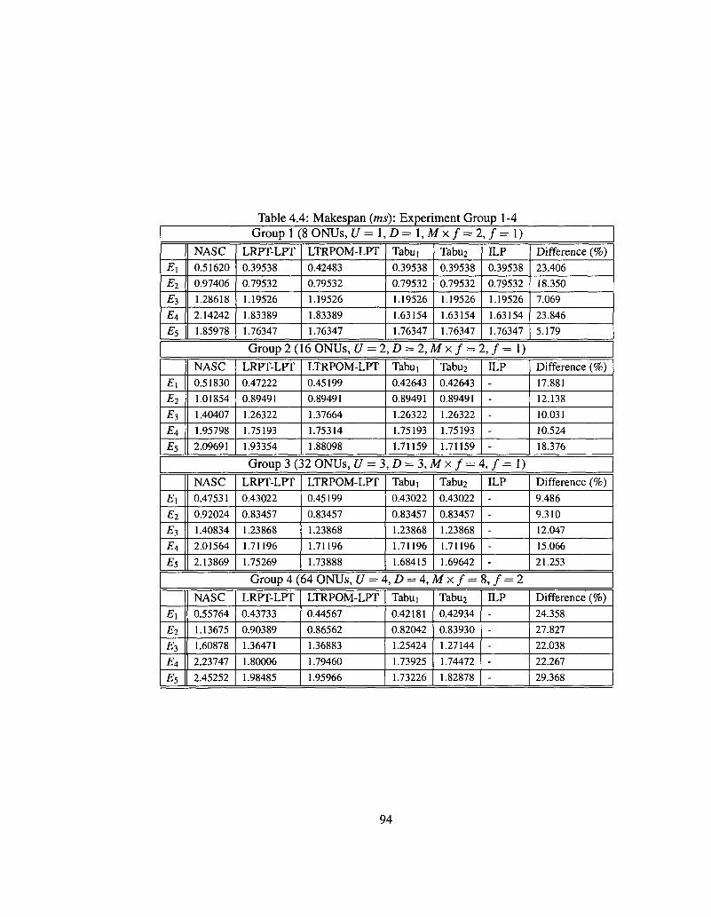
Table 4.4: Makespan (ms): Experiment Group 1-4 Group 1 (8 ONUs, U =l,D=l,Mxf = 2,f=l)
£i E2
E3
£ 4
£5
NASC
0.51620
0.97406
1.28618
2.14242
1.85978
LRPT-LPT
0.39538
0.79532
1.19526
1.83389
1.76347
LTRPOM-LPT
0.42483
0.79532
1.19526
1.83389
1.76347
Tabui
0.39538
0.79532
1.19526
1.63154
1.76347
Tabu2
0.39538
0.79532
1.19526
1.63154
1.76347
ILP
0.39538
0.79532
1.19526
1.63154
1.76347
Difference (%)
23.406
18.350
7.069
23.846
5.179
Group 2 (16 ONUs, U = 2, D = 2, M x / = 2, / = 1)
£1
E2
£3
£4
£5
NASC
0.51830
1.01854
1.40407
1.95798
2.09691
LRPT-LPT
0.47222
0.89491
1.26322
1.75193
1.93354
LTRPOM-LPT
0.45199
0.89491
1.37664
1.75314
1.88098
Tabui
0.42643
0.89491
1.26322
1.75193
1.71159
Tabu2
0.42643
0.89491
1.26322
1.75193
1.71159
ILP
-
-
-
-
-
Difference (%)
17.881
12.138
10.031
10.524
18.376
Group 3 (32 ONUs, £/ = 3, D = 3, M x / = 4, / = 1)
£1
£2
£3
£4
£5
NASC
0.47531
0.92024
1.40834
2.01564
2.13869
LRPT-LPT
0.43022
0.83457
1.23868
1.71196
1.75269
LTRPOM-LPT
0.45199
0.83457
1.23868
1.71196
1.73888
Tabui
0.43022
0.83457
1.23868
1.71196
1.68415
Tabu2
0.43022
0.83457
1.23868
1.71196
1.69642
ILP
-
-
-
-
-
Difference (%)
9.486
9.310
12.047
15.066
21.253
Group 4 (64 ONUs, [/ = 4,/) = 4 , M x / = 8 , / = 2
£1
£2
£3
£4
£5
NASC
0.55764
1.13675
1.60878
2.23747
2.45252
LRPT-LPT
0.43733
0.90389
1.36471
1.80006
1.98485
LTRPOM-LPT
0.44567
0.86562
1.36883
1.79460
1.95966
Tabui
0.42181
0.82042
1.25424
1.73925
1.73226
Tabu2
0.42934
0.83930
1.27144
1.74472
1.82878
ILP
-
-
-
-
-
Difference (%)
24.358
27.827
22.038
22.267
29.368
94
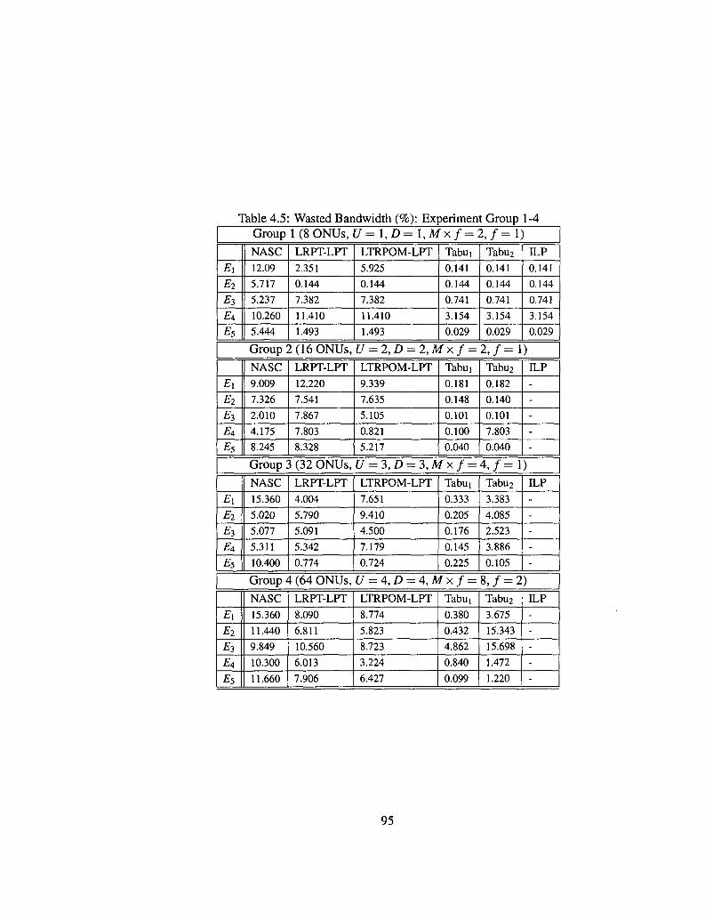
Table 4.5: Wasted Bandwidth (%): Experiment Group 1-4 Group 1 (8 ONUs , U = l,D=l,Mxf = 2,f=\)
Ei
E2
£3 EA
E5
NASC
12.09
5.717
5.237
10.260
5.444
LRPT-LPT
2.351
0.144
7.382
11.410
1.493
LTRPOM-LPT
5.925
0.144
7.382
11.410
1.493
Tabui
0.141
0.144
0.741
3.154
0.029
Tabu2
0.141
0.144
0.741
3.154
0.029
ILP
0.141
0.144
0.741
3.154
0.029
Group 2 (16 ONUs , U = 2, D = 2, M x / = 2, / = 1)
Ex
E2
£3
£4
E5
NASC
9.009
7.326
2.010
4.175
8.245
LRPT-LPT
12.220
7.541
7.867
7.803
8.328
LTRPOM-LPT
9.339
7.635
5.105
0.821
5.217
Tabui
0.181
0.148
0.101
0.100
0.040
Tabu2
0.182
0.140
0.101
7.803
0.040
ILP
-
-
-
-
-
Group 3 (32 ONUs , U = 3, D = 3, M x / = 4, / = 1)
£1
E2
£3
£4
£5
NASC
15.360
5.020
5.077
5.311
10.400
LRPT-LPT
4.004
5.790
5.091
5.342
0.774
LTRPOM-LPT
7.651
9.410
4.500
7.179
0.724
Tabui
0.333
0.205
0.176
0.145
0.225
Tabu2
3.383
4.085
2.523
3.886
0.105
ILP
-
-
-
-
-
Group 4 (64 ONUs , [/ = 4, D = 4, M x / = 8, / = 2)
E\
E2
£3
£ 4
£5
NASC
15.360
11.440
9.849
10.300
11.660
LRPT-LPT
8.090
6.811
10.560
6.013
7.906
LTRPOM-LPT
8.774
5.823
8.723
3.224
6.427
Tabui
0.380
0.432
4.862
0.840
0.099
Tabu2
3.675
15.343
15.698
1.472
1.220
ILP
-
-
-
-
-
95

respectively, to simulate a high WDM downstream traffic scenario.
For each experiment, we ran tabu search for three times, each time the tabu procedure was
initialized by feasible solution obtained from each dispatching rule as mentioned above. The best
solution found among the three is used as the result of this experiment. Two versions of Tabu are
considered, where in one (Tabuj) all types of moves (mentioned earlier) are considered; in another
version (Tabu2), we assume a predetermined wavelength selection (e.g., according to the NASC),
and we consider only neighborhoods that are obtained (from a possible feasible solution) by revert
ing the transmitting order of two or three consecutive critical operations or grants of the same ONU,
or, by reverting the transmitting order of two or three consecutive critical grants of different ONUs
on the same wavelength. The results of our experiments are listed in Table 4.4 and Table 4.5.
Our objective is to search for schedules with shorter/minimum makespan. In each group, as ex
pected, a simple rule such as NASC results in a solution with longer makespan, as shown in Table
4.4. As indicated by the "Difference" column, the performance gain of Tabu over the worst solution
(i.e., NASC) varies from as low as 5.179% to as high as 29.368%, indicating remarkable improve
ment that can be achieved by appropriate grant scheduling. The LRPT-LPT and LTRPOM-LPT
normally yields better performance than NASC, due to the fact that they tend to first schedule those
ONUs with higher total traffic demands and larger transmission windows, and these rules generally
tend to better utilize the medium and leave fewer gaps on each transmission channel. As we we
also see from Table 4.4, in some instances they give as good a solution as Tabu when the number
of ONUs and wavelengths in the network is small (e.g., group 1) and the performance degrades in
other scenarios.
We note that Tabu only yields a local optimal solution; we also obtained the global optimal after
solving the MILP for small instances (e.g., 8 ONUs and 4 to 5 channels; the CPLEX run time for
5 channels exceeded 10 hours for one experiment with optimality gap around 10%). Clearly, Tabu
96
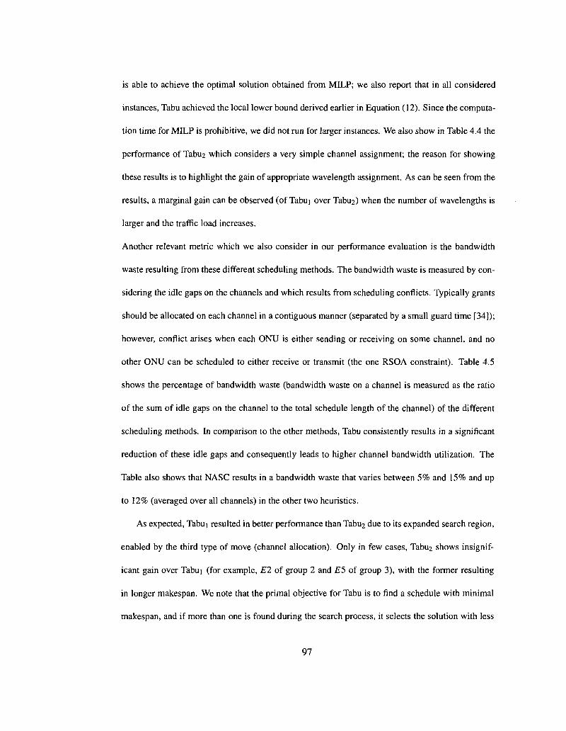
is able to achieve the optimal solution obtained from MILP; we also report that in all considered
instances, Tabu achieved the local lower bound derived earlier in Equation (12). Since the computa
tion time for MILP is prohibitive, we did not run for larger instances. We also show in Table 4.4 the
performance of Tabu2 which considers a very simple channel assignment; the reason for showing
these results is to highlight the gain of appropriate wavelength assignment. As can be seen from the
results, a marginal gain can be observed (of Tabui over Tabu2> when the number of wavelengths is
larger and the traffic load increases.
Another relevant metric which we also consider in our performance evaluation is the bandwidth
waste resulting from these different scheduling methods. The bandwidth waste is measured by con
sidering the idle gaps on the channels and which results from scheduling conflicts. Typically grants
should be allocated on each channel in a contiguous manner (separated by a small guard time [34]);
however, conflict arises when each ONU is either sending or receiving on some channel, and no
other ONU can be scheduled to either receive or transmit (the one RSOA constraint). Table 4.5
shows the percentage of bandwidth waste (bandwidth waste on a channel is measured as the ratio
of the sum of idle gaps on the channel to the total schedule length of the channel) of the different
scheduling methods. In comparison to the other methods, Tabu consistently results in a significant
reduction of these idle gaps and consequently leads to higher channel bandwidth utilization. The
Table also shows that NASC results in a bandwidth waste that varies between 5% and 15% and up
to 12% (averaged over all channels) in the other two heuristics.
As expected, Tabui resulted in better performance than Tabu2 due to its expanded search region,
enabled by the third type of move (channel allocation). Only in few cases, Tabu2 shows insignif
icant gain over Tabui (for example, E2 of group 2 and E5 of group 3), with the former resulting
in longer makespan. We note that the primal objective for Tabu is to find a schedule with minimal
makespan, and if more than one is found during the search process, it selects the solution with less
97

Table 4.6: Experiment
Number of SG-EPONs 4
Data rate of WDM/AWG wavelengths 1 Gbps
Delay between OLTs 200^(40A:m)
Delay between ONU and Local OLT 100ps(20km)
Number of WDM/LR ONU in each EPON 16/16
Queue size at OLT/ONU 10/lMBytes
idle gaps. It is clear from Table 4.5 that a minimum schedule length does reduce these idle gaps.
Now as mentioned before, as the number of wavelengths increases, the benefits of wavelength allo
cation becomes more apparent. One interesting observation is the large bandwidth waste resulting
from Tabu2 in Group 4, for experiments Ei and £3. We observed that this large waste occurs on
the downstream channels, that have light loads (as per the experiment setup); here, although reshuf
fling the grants on their corresponding channels has resulted in shorter makespan (Table 4.4), the
selected schedule has forced the downstream grants to be relocated, apart from each other (to avoid
conflicts with concurrent transmissions on other channels), leaving more idle gaps. We note that
other solutions using Tabu2 have been found with lower bandwidth waste but longer makespan and
hence were ignored; for example, in E%, Tabu2 initialized with LRPT yielded a waste of 2.807% and
a makespan of 0.85628m,s.
4.7 Simulation Results
We carry out packet-level simulation to study the performance of the proposed scheduling methods;
we simulated the operation of Stargate and SG-EPON using OMNet++, a discrete event simulator
[61]. The simulation parameters are shown in Table 4.6. We considered the five experiments in
Group 3 (traffic profile is explained in the previous section) to obtain the numerical results. In each
98
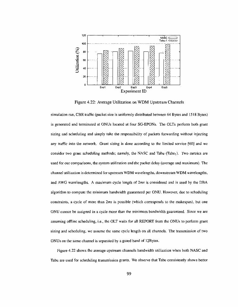
c o
N
120
100
80
60
40
20
NASC Tabu-1
I I
I I" I-8
I t I I.. I ^
Exp1 Exp2 Exp3 Exp4
Experiment ID Exp5
Figure 4.22: Average Utilization on WDM Upstream Channels
simulation run, CBR traffic (packet size is uniformly distributed between 64 Bytes and 1518 Bytes)
is generated and terminated at ONUs located at four SG-EPONs. The OLTs perform both grant
sizing and scheduling and simply take the responsibility of packets forwarding without injecting
any traffic into the network. Grant sizing is done according to the limited service [60] and we
consider two grant scheduling methods; namely, the NASC and Tabu (Tabui). Two metrics are
used for our comparisons, the system utilization and the packet delay (average and maximum). The
channel utilization is determined for upstream WDM wavelengths, downstream WDM wavelengths,
and AWG wavelengths. A maximum cycle length of 2ms is considered and is used by the DBA
algorithm to compute the minimum bandwidth guaranteed per ONU. However, due to scheduling
constraints, a cycle of more than 2ms is possible (which corresponds to the makespan), but one
ONU cannot be assigned in a cycle more than the minimum bandwidth guaranteed. Since we are
assuming offline scheduling, i.e., the OLT waits for all REPORT from the ONUs to perform grant
sizing and scheduling, we assume the same cycle length on all channels. The transmission of two
ONUs on the same channel is separated by a guard band of 12Bytes.
Figure 4.22 shows the average upstream channels bandwidth utilization when both NASC and
Tabu are used for scheduling transmission grants. We observe that Tabu consistently shows better
99

-
a o <x> N
D
120
100
80
60
40
20
0 Exp1 Exp2 Exp3 Exp4 Exp5
Experiment ID
Figure 4.23: Average Utilization on WDM Downstream Channels
utilization than NASC. At low loads (e.g., Expl), the bandwidth utilization is low (close to 80%)
for both methods; this is due to the fact that the scheduling or cycle length is very small (please
see Table 4.4) and hence the overhead from the guard bands become more significant. Bandwidth
may also be wasted due to conflict in scheduling: as we showed in Table 4.5, NASC results in much
larger idle gaps (than Tabu), and obviously that results in lower utilization. One last reason, which
we also observed, is that the schedule finish time for all wavelengths is not the same (though the
transmission cycle is the same); this leaves some idle gaps on some channels until the next cycle
starts. When the load increases, the channel utilization (under Tabu) increases, since the makespan
becomes longer and the Guard band overhead becomes negligible, and the bandwidth waste is also
negligible (Table 4.5); NASC on the other hand suffers from lower utilization mainly due to the
bandwidth waste on the channels. Figure 4.23 shows the average downstream channel utilization.
For the first 4 experiments, the channel utilization decreases which immediately follows from the
fact that for these experiments, while the upstream load increases, we kept the downstream load low
and constant (5%-25% from the minimum bandwidth guaranteed); as the upstream load increases,
the makespan increases, and the idle gaps on the downstream channels become larger. However, in
Exp5, the downstream traffic profile changes (75%-95%) and the channel utilization improves. We
100
NASC I I Tabu-1 E X X H J

§ 03 N
120
100
80
60
40
20
NASC Tabu-1
s
• 5 : ST •» 1 • i I g
Exp1 Exp2 Exp3 Exp4
Experiment ID Exp5
Figure 4.24: Average Utilization on AWG Channels
100 -
S 10 r
Exp1 Exp2 Exp3 Exp4
Experiment ID Exp5
Figure 4.25: Average WDM Upstream Traffic Delay
note however that Tabu has consistently shows better performance than NASC. Finally, the average
AWG channel utilization is shown in Figure 4.24, where similar observations can be made as before
with respect to the performance of Tabu over NASC.
Figures 4.25 and 4.26 show the average and maximum packet delay observed on upstream
channels (at the OLT) for the two scheduling methods and for various experiments. Clearly, as the
load increases (going from E\ to £5), the delay increases, with little difference at low loads between
NASC and Tabu. This is attributed to the fact that at these low loads, the cycle length is too small,
and all ONUs are assigned bandwidth as much as they request, leaving almost no packets in the
101

*~===^r- " ^ K
NASC 1 '
Tabu-1 X j i i
Exp1 Exp2 Exp3 Exp4 Exp5
Experiment ID
Figure 4.26: Maximum WDM Upstream Traffic Delay
ONUs' buffers and hence a very small or negligible queuing delays. However, as the load increases,
the makespan and hence the cycle length increases; under NASC, the makespan is more than 2ms
while the minimum bandwidth guaranteed (assigned to the ONU) maintains the same value (the one
computed based on 2ms cycle length). Therefore, the ONU cannot transmit all its buffered packets
in the same cycle, and some packets will inevitably be queued. As the simulation time elapses, these
buffers build up and the queuing delays become excessively high, as shown in the Figure. Under
Tabu scheduling, the cycle length is always less than 2ms and the bandwidth allocated per ONU is
sufficient to transmit all frames in the buffer.
4.8 Summary
We studied the problem of joint grant scheduling and wavelength assignment in a novel multichan
nel optical access network and we formulated it as an Open Shop. A MILP formulation is presented
for the joint problem; since the problem is shown to be NP-hard, only small instances can be solved
to optimality. A Tabu Search is accordingly presented and its performance is shown to be as good
100
Q
102

as that of MILP for small instances. Tabu also shows a performance improvement (over other con
sidered heuristics) by achieving a smaller scheduling length (a difference of 29%) with substantial
reduction in channel idle gaps (a difference of 15%) yielding to much higher channel utilization and
lower queuing delays. We also observed the benefits of wavelength allocation in solving the joint
problem when the number of channels in the network is not small. A packet-level simulation on
the considered network is also presented and significant improvements are shown both in terms of
system utilization and packet queuing delays.
This work can be extended by revising the scheduling policy and considering a mixture of offline
and online scheduling in the model. Also, since solving the Open Shop to optimality is very difficult,
decomposing the problem would be an interesting future direction, where instead of enumerating
all elements in Q., only those that yield an improvement may be considered.
103

Chapter 5
Conclusion & Future Work
5.1 Conclusion
Ethernet Passive Optical Networks (EPONs) have emerged as the best solution to solve the last mile
bottleneck problem. In this thesis, we proposed the STARGATE/SG-EPON metro-access network
the provides an all optical solution to integrate the fiber-based access and metro network in a pay-
as-you-grow manner. It offers a high speed, reliability, scalability, but low-cost, WDM upgraded
network environment to provide support for new bandwidth consuming applications.
In the first two chapters, we introduced today's PON technologies as well as some related re
search work. We discussed technical details of EPON and its advantages compared to other PON
technologies. We also provided a brief description of the DBA algorithm.
In Chapter 3, we presented the state-of-the-art STARGATE/SG-EPON architecture, and three
types of ONU designed with backward compatibility to protect previous investment. Considering all
hardware constraints imposed by SG-EPON, we developed a limited service based DBA algorithm
for effective resource management. Our simulation results showed that, with each upgrade (TDM
104

ONU to WDM ONU, WDM ONU to LR ONU), the performance of network is improved greatly,
in terms of both traffic delay and throughput. However, we also observed that, due to the RSOA
constraint, a simple grant scheduling scheme does not guarantee any optimal (or near optimal)
allocation, which is the motivation of our second contribution in the next chapter.
Due to the fact that, a more elaborate scheduling policy is required to produce better sched
ule with less idle gaps. Hence, we investigated grant scheduling problem based on the schedule
theory as presented in Chapter 4. Our objective is to reduce the schedule length, which will of
course increase the channel utilization as well as reduce the queuing delay experienced by upstream
data packets at ONUs. We introduced an efficient scheduling policy and formulated it using Mixed
Integer Linear Programming (MILP) technique. Significantly improvement is observed from our
performance and simulation results, that our heuristic scheduling policies produce better sched
ule achieving smaller schedule length(5.2% — 29% difference from simple schedule schemes) with
substantial reduction in channel idle gaps.
5.2 Future Work
Our research work still leaves some potential interesting issues that can be further studied. We state
these issues as follows:
• Some extensions to our work in Chapter 3, especially to our proposed DBA algorithm. In
SG-EPON, this algorithm can be further extended to support QoS, which provides end user
applications with an agreed upon degree of performance [70,71].
• Another potential avenue for research is to include QoS to our heuristic grant scheduling
policies, to supply the on-time delivery capabilities to various types of user applications.
• Yet another alternative issue is to extend and examine our DBA algorithm with some different
105

traffic patterns, such as short range dependent traffic (can be modeled using Markov processes
and regression models), or long range dependent traffic (can be modeled using fractional
autoregressive integrated moving average (F-ARIMA) and fractional Brownian motion [72]).
• In Chapter 4, the MILP for our OSP problem is not scalable and hence we did not run MILP
for larger number of ONUs. Instead, some decomposition methods can be applied, for ex
ample, Column Generation or Benders' Decomposition as in [73], to solve this NP-hard
problem.
106

Bibliography
[1] Martin Maier, Martin Herzog, and Martin Reisslein. STARGATE: The Next Evolutionary
Step toward Unleashing the Potential of WDM EPONs. IEEE Communications Magazine,
45(5):50-56, May 2007.
[2] R. Ramaswami. Optical Networking Technologies: What Worked and What Didn't. IEEE
Communications Magazine, 44(9): 132-139, September 2006.
[3] P. W. Shumate. Fiber-to-the-Home: 1997-2007. IEEE/OSA Journal of Lightwave Technology,
26(9): 1093-1103, May 2008.
[4] P. E. Green. Fiber To The Home-The New Empowerment. Wiley, 2006.
[5] K. G. Coffman and A. M. Odlyzko. Internet growth: Is there a "Moore's Law" for data
traffic? J.Abello, P.M. Pardalos, and M. G. C. Resende, eds., Kluwer, 2001.
[6] H. Shinohara. Broadband Access in Japan: Rapidly Growing FTTH Market. IEEE Communi
cations Magazine, pages 72-78, September 2005.
[7] Michael P. Mcgarry. Multi-channel Ethernet Passive Optical Networks. PhD thesis, Arizona
State University, 2007.
[8] Ahmad R. Dhaini. Design and Analysis of Next Generation Ethernet-Based Passive Optical
Access Networks. Master's thesis, Concordia University, 2006.
107
[9] G. Kramer, B. Mukherjee, and G. Pesavento. Ethernet Passive Optical Network (EPON):
Building a Next-Generation Optical Access Network. IEEE Communications Magazine, pages
66-73, February 2002.
[10] ITU-T. G.983.1 - Broadband Passive Optical Networks (BPON): General characteristics, June
1999.
[11] Ingrid Van de Voorde and Gert Van der Plas. Full Service Optical Access Networks: ATM
Transpot on Passive Optical Networks. IEEE Communications Magazine, 35(4):7075, 1997.
[12] Kyeong Soo Kim. On the Evolution of PON Based FTTH Solutions. Stanford Networking
Research Center, 2002.
[13] M. Hajduczenia, H. J. A. da Silva, and P. P. Monteiro. EPON versus APON and GPON: a
detailed performance comparison. Journal of Optical Networking, 5(4):298-319, April 2006.
[14] N. Frigo, P. Iannone, P. Magill, T. Darcie, M. Downs, B. Desai, U. Koren, T. Koch, C. Dragone,
H. Presby, and G. Bodeep. A wavelength-division multiplexed passive optical network with
cost-shared components. IEEE Photonic Technology Letters, 6(11): 1365-1367, November
1994.
[15] F. T. An, K. S. Kim, D. Gutierrez, S. Yam, S. T. Hu, K. Shrikhande, and L. G. Kazovsky.
SUCCESS: A Next-Generation Hybrid WDM/TDM Optical Access Network Architecture.
IEEE/OSA Journal of Lightwave Technology, 22(11):2557-2569, November 2004.
[16] Y. L. Hsueh, M. S. Rogge, S. Yamamoto, and L. Kazovsky. A highly flexible and efficient
passive optical network employing dynamic wavelength allocation. IEEE/OSA Journal of
Lightwave Technology, 23(l):277-286, January 2005.
108
[17] C. Bock, J. Prat, and S. D. Walker. Hybrid WDM/TDM PON using the AWG FSR and featur
ing Centralized Light Generation and Dynamic Bandwidth Allocation. IEEE/OSA Journal of
Lightwave Technology, 23(12):3981-3988, December 2005.
[18] Amitabha Banerjee, Youngil Park, Frederick Clarke, Huan Song, Sunhee Yang, Glen Kramer,
Kwangjoon Kim, and Biswanath Mukherjee. Wavelength-division-multiplexing passive opti
cal network (WDM-PON) technologies for broadband access: a review [Invited]. Journal of
Optical Networking, 4(11):737-758, November 2005.
[19] L. Noirie. The Road Towards All-Optical Networks. In Proc, Optical Fiber Communication
Conference (OFC), volume 2, pages 615-616, March 2003.
[20] M. Kuznetsov, N. M. Froberg, S. R. Henion, H. G. Rao, J. Korn, K. A. Rauschenbach, E. H.
Modiano, and V. W. S. Chan. A Next-Generation Optical Regional Access Network. IEEE
Communications Magazine, 38(l):66-72, January 2000.
[21] N. M. Froberg, S. R. Henion, H. G. Rao, B. K. Hazzard, S. Parikh, B. R. Romkey,
and M. Kuznetsov. The NGI ONRAMP Test Bed: Recongurable WDM Technology for
Next Generation Regional Access Networks. IEEE/OSA Journal of Lightwave Technology,
18(12):1697-1708, December 2000.
[22] W. T. Shaw, G. Kalogerakis, S. W. Wong, Y. L. Hsueh, N. Cheng, S. H. Yen, M. E. Marhic, and
L. G. Kazovsky. MARIN: Metro-Access Ring Integrated Network. In Proc, IEEE GLOBE-
COM, San Francisco, CA, Nov./Dec. 2006.
[23] S. W. Wong, W. T. Shaw, K. Balasubramaniam, N. Cheng, and L. G. Kazovsky. MARIN:
Demonstration of a Flexible and Dynamic Metro-Access Integrated Architecture. In Proc,
IEEE GLOBECOM, Washington, DC, November 2007.
109

[24] J. Segarra, V. Sales, and J. Prat. An All-Optical Access-Metro Interface for Hybrid
WDM/TDM PON Based on OBS. IEEE/OSA Journal of Lightwave Technology, 25(4):1002-
1016, April 2007.
[25] I. Van de Voorde, C. M. Martin, J. Vandeweg, and X. Z. Qiu. The SuperPON Demonstrator:
An exploration of possible evolution paths for optical access networks. IEEE Communications
Magazine, 38(2):74-82, February 2000.
[26] D. G. Mestdagh and C. M. Martin. The Super-PON concept and its technical challenges.
Broadband Commun., April 1996.
[27] C. Martin, H. Slabbinck, P. Vetter, X.-Z. Qiu, J. Vandewege, P. Solina, D. Haux, G. van den
Hoven, and A. Boot. Realization of a SuperPON demonstrator. In Proc, NOC'97, page
18893, June 1997.
[28] M. Oskar van Deventer, Y. M. van Dam, P. J. M. Peters, F. Vermaerke, and A. J. Phillips.
Evolution phases to an ultra-broadband access network: Results from ACTS-PLANET. IEEE
Communications Magazine, 35(12):72-77, December 1997.
[29] I. Van de Voorde, M. Oskar van Deventer, P. J. M. Peters, P. Crahay, E. Jaunart, A. J. Phillips,
J. M. Senior, X. Z. Qiu, J. Vandewege, J. J. M. Binsma, and P. J. Vetter. Network topologies for
SuperPON. Optical Fiber Communication. OFC 97., Conference on, 16(21):57-58, February
1997.
[30] Huan Song, Byoung-Whi Kim, and Biswanath Mukherjee. Multi-thread polling: a dynamic
bandwidth distribution scheme in long-reach PON. IEEE Journal on Selected Areas in Com
munications, '21'(2): 134-142, February 2009.
110
[31] IEEE Standard for Information technology - Telecommunications and information exchange
between systems - Local and metropolitan area networks - Specific Requirements. Part
3: Carrier sense multiple access with collision detection (CSMA/CD) access method and
physical layer specification, ansi/ieee std 802.3-2002, 2002 edition. Available at h t t p :
/ / s t a n d a r d s . i e e e . o r g / g e t i e e e 8 0 2 / d o w n l o a d / 8 0 2 . 3 - 2 0 0 2 . p d f .
[32] K. Claffy, G. Miller, and K. Thompson. The nature of the beast: Recent traffic
measurements from an internet backbone. In Proc, INET'98, (Geneva, Switzerland),
July 1998. Available at h t t p : / / w w w . i s o c . o r g / i n e t 9 8 / p r o c e e d i n g s / 6 g / 6 g \
t e x t u n d e r s c o r e 3 . h t m .
[33] S. Clavenna. Metro Optical Ethernet. Lightreading (www.lightreading.com), November 2000.
[34] G. Kramer, B. Mukherjee, and G. Pesavento. Ethernet PON (ePON): Design and Analysis of
an Optical Access Network. Photonic Network Communications, 3:307-319, 2001.
[35] GR-1209-CORE for passive fiber optic components.
[36] GR-1221-CORE for passive fiber optic component reliability.
[37] G. Kramer, B. Mukherjee, and A. Maislos. Ethernet Passive Optical Networks. John Wiley
& Sons, Inc., March 2003. In S. Dixit, editor, Multiprotocol over DWDM: Building the Next
Generation Optical Internet.
[38] G. Kramer, B. Mukherjee, and G. Pesavento. Interleaved Polling with Adaptive Cycle Time
(IPACT): A Dynamic Bandwidth Distribution Scheme in an Optical Access Network. Pho
tonic Network Communications, 4(1):89-107, January 2002.
[39] IEEE 802.3ah, Ethernet in the first Mile Task Force, available at h t t p : / /www. i e e e 8 02 .
o r g / 3 / e f m / i n d e x . h t m l .
I l l

[40] K. H. Kwong, D. Harle, and I. Andonovic. Dynamic Bandwidth Allocation Algorithm for
Differentiated Services over WDM EPONs. In Proc, The Ninth International Conference on
Communications Systems, pages 116-120, September 2004.
[41] Michael McGarry. An evolutionary wavelength division multiplexing upgrade for ethernet
passive optical networks. Master's thesis, Arizona State University, 2004.
[42] F. Clarke, S. Sarkar, and B. Mukherjee. Simultaneous and interleaved polling: an upstream
protocol for wdm-pon. In Proc, Optical Fiber Communication Conference (OFC), page 3,
March 2006.
[43] M.P. Michael, M. Reisslein, C.J. Colbourn, M. Maier, F. Aurzada, and M. Scheutzow. Just-in-
Time Scheduling for Multichannel EPONs. Lightwave Technology, Journal of 26(10):1204-
1216, May 2008.
[44] T. Koonen. Fiber to the Home/Fiber to the Premises: What, Where, and When. In Proc,
IEEE, volume 94, pages 911-934, May 2006.
[45] F. Davik, M. Yilmaz, S. Gjessing, and N. Uzun. IEEE 802.17 Resilient Packet Ring Tutorial.
IEEE Communications Magazine, 42(3): 112-118, March 2004.
[46] M. P. McGarry, M. Maier, and M. Reisslein. WDM Ethernet Passive Optical Networks. IEEE
Communications Magazine, 44(2):S18-S25, February 2006.
[47] R. Sananes, C. Bock, and J. Prat. A Techno-economic Comparison of Optical Access Net
works. Proc, International Conference on Transparent Optical Networks, Barcelona, Spain,
2:201-204, July 2005.
112

[48] A. R. Dhaini, C. M. Assi, M. Maier, and A. Shami. Dynamic Wavelength and Bandwidth
Allocation in Hybrid TDM/WDM Ethernet Passive Optical Networks (EPONs). Lightwave
Technology, Journal of, 25(l):277-286, January 2007.
[49] W. Hung, C. K. Chan, L. K. Chan, and F. Tong. An Optical Network Unit for WDM Access
Networks with Downstream DPSK and Upstream Remodulated OOK Data Using Injection-
locked FP Laser. IEEE Photonic Technology Letters, 15(10): 1476-1478, October 2003.
[50] H. D. Kim, S. G. Kang, and C. H. Lee. A Low-cost WDM Source with an ASE Injected Fabry-
Perot Semiconductor Laser. IEEE Photonic Technology Letters, 12(8):1067-1069, August
2000.
[51] E. Wong, K. L. Lee, and T. B. Anderson. Directly Modulated Self-Seeding Reflective Semi
conductor Optical Amplifiers as Colorless Transmitters in Wavelength Division Multiplexed
Passive Optical Networks. IEEE/OSA Journal of Lightwave Technology, 25(l):67-74, January
2007.
[52] J. Prat et al. Optical Network Unit based on a Bidirectional Reflective Semiconductor Optical
Amplifier for Fiber-to-the-Home Networks. IEEE Photonic Technology Letters, 17(1):250-
252, January 2005.
[53] M. D. Feuer et al. Single-port Laser-amplifier Modulators for Local Access. IEEE Photonic
Technology Utters, 8(9):1175-1177, September 1996.
[54] M. Fujiwara, J. Kani, H. Suzuki, and K. Iwatsuki. Impact of Backreflection on Upstream
Transmission in WDM Single-Fiber Loopback Access Networks. IEEE/OSA Journal of Light
wave Technology, 24(2):740-746, February 2006.
113
[55] F. Payoux, P. Chanclou, T. Soret, and N. Genay. Demonstration of a RSOA-based Wave
length Remodulation Scheme in 1.25 Gbit/s Bidirectional Hybrid WDM-TDM PON. In
Proc, Optical Fiber Communication Conference/National Fiber Optic Engineers Conference
(OFC/NFOEC), March 2006.
[56] J.-H. Moon, K.-M. Choi, S.-G. Mun, and C.-H. Lee. Effects of Black-Reflection in WDM-
PONs Based on Seed Light Injection. IEEE Photonic Technology Letters, 19(24):2045-2047,
December 2007.
[57] C. M. Assi, Y. Ye, and S. Dixitand M. A. Ali. Dynamic Bandwidth Allocation for Quality-
of-Service over Ethernet PONs. IEEE Journal on Selected Areas in Communications,
21(9):1467-1477, November 2003.
[58] M. P. McGarry, M. Reisslein, M. Maier, and A. Keha. Bandwidth Management for WDM
EPONs. OSA Journal of Optical Networking, 5(9):637-654, September 2006.
[59] M. P. McGarry, M. Reisslein, and M. Maier. Ethernet Passive Optical Network Architectures
and Dynamic Bandwidth Allocation Algorithms. IEEE Communications Surveys and Tutori
als, 10(3):46-60, Third Quarter 2008.
[60] G. Kramer, B. Mukherjee, and G. Pesavento. IPACT: A Dynamic Protocol for an Ethernet
PON (EPON). IEEE Communications Magazine, 40(2):74-80, February 2002.
[61] OMNet website: h t t p : //www. omnetpp . o r g / , last accessed in March 2009.
[62] M. Gagnaire and M. Koubaa. A new control plane for next-generation WDM-PON access
systems. IEEE-ICST AccessNets '07, August 2007. Ottawa, Canada.
[63] Michael Pinedo. Theory, Algorithms, and Systems. Springer, third edition, 2008.
114

[64] Teofilo F. Gonzalez and Sartaj Sahni. Open Shop Scheduling to Minimize Finish Time. J.
ACM, 23(4):665-679, 1976.
[65] L. Meng, C. Assi, M. Maier, and A. Dhaini. Resource Management in Stargate-based Ethernet
Passive Optical Networks (SG-EPONs). To appear in Proc. oj"ICC '09, IEEE, June 2009.
[66] Selcuk Colak and Anurag Agarwal. Non-Greedy Heuristics and Augmented Neural Networks
for the Open-Shop Scheduling Problem. Published online 25 July 2005 in Wiley InterScience.
[67] D. Alcaide, J. Sicilia, and D. Vigo. A Tabu Search Algorithm for the Open Shop Problem.
Sociedadde Estadistica e Investigacion Operativa, 5(2):283-296, Top(1997).
[68] Mauro Dell'Amico and Marco Trubian. Applying tabu search to the job-shop scheduling
problem. Annals of Operation Research, 41:231-252, 1993.
[69] CPLEX. Using the CPLEX Callable Library (Version 9.1.3). CPLEX Optimization Inc., 2005.
[70] Yishay Mansour and Boaz Pat-Shamir. Jitter Control in QOS Networks. IEEE/ACM Transac
tions on Networking, 9(4):492-502, August 2001.
[71] Ahmad R. Dhaini, Chadi M. Assi, Martin Maier, and Abdallah Shami. Per-Stream QoS and
Admission Control in Ethernet Passive Optical Networks (EPONs). Lightwave Technology,
Journal of, 25(7): 1659-1669, July 2007.
[72] A. Adas and Amarnath Mukherjee. On Resource Management and QOS Guarantees For Long
Range Dependent Traffic. In Proc, IEEEINFOCOM'95, pages 779-787, 1995.
[73] Ching-Fang Liaw. An iterative improvement approach for the nonpreemptive open shop
scheduling problem. Europeaan Journal of Operational Research 111 (1998), pages 509-
517.
115

[74] Kyeong Soo Kim, David Gutierrez, Fu-Tai An, and Leonid G. Kazovsky. Design and Perfor
mance Analysis of Scheduling Algorithms for WDM-PON under SUCCESS-HPON Archi
tecture. IEEE/OSA Journal of Lightwave Technology, 23(11):3716-3731, November 2005.
[75] Andras Varga. Using the OMNet++ Discrete Event Simulation System in Education. IEEE
Transaction on Education, 42(4), November 1999.
[76] S. Wang, K. Z. Liu, and F. P. Hu. Simulation of Wireless Sensor Networks Localization with
OMNet++. Department of Electronics and Information Huazhong University of Science and
Technology, Wuhan City, P. R. China, 2007.
[77] Ertan Onur, Cem Ersoy, Hakan Deli?, and Lale Akarun. Surveillance Wireless Sensor Net
works: Deployment Quality Analysis using OMNet++. Bog"azici University, Turkey, 2005.
[78] Vishal Jain and Monika Jain. Queuing Network Model for Link and Path Availability of
Ad hoc Networks. Wireless and Optical Communications Networks, Proceedings 2006IFIP
International Conference on Wireless and Optical Networking.
[79] Jing Xu and Zhang Jing. Hotspot Clustering for Ad hoc Network. Wireless Communica
tions, Networking and Mobile Computing 2005, Proceedings 2005 International Conference
on Networking and Mobile Computing, 2, 23-26:751-755, September 2005.
[80] Website: h t t p : / /www. omnes t . com/.
116

Appendix A
Simulation Tool: OMNet++
Here, we will briefly introduce OMNet++, the software that we used to simulate our SG-EPON and
STARGATE metro-access networks.
A.0.1 Why OMNet++
OMNet++ [61] is an open source, discrete-event driven simulation platform used in communication
networks, protocol modeling, modeling queuing networks, validating hardware architecture, and
evaluating performance aspects of complex communications systems. Particularly, it can be used
to model a wide range of networks, e.g., Direct Access Networks and LANs. In many literature,
OMNet++ was used as simulation tool to model networks such as WDM-PON, Wireless Sensor
network, TD-SCDMA for cellular networks, HPONs, etc. [7,74-79]. Some advanced features of
OMNet++ can be described as follows [80]:
1. Hierarchical, component-based modeling: Models are built from self-contained compo
nents using a high-level declarative language (NED), with arbitrary levels of nesting.
2. C++-based, high performance simulation kernel: Atomic components are written in C++,
117
using a well-defined API to the simulation library. It provides high event/sec throughput.
3. Wide range of applicability: It is designed for multi-purposes such as queuing networks,
business process and high-level architectures. In addition, it is widely used in academia for
wired and wireless communication network simulation.
4. Models are self-documenting: Variety of high-quality documentation can be generated from
commented model source code, e.g., diagrams, tables and cross-references.
5. Open interfaces: Input and output can be either plain text and/or XML. It is easy to process
the collected results with 3rd party tools, for example, Matlab or MS Excel.
6. Wide range of open-source simulation models: TCP/IP, IPv6, MPLS, and other models are
available from [61].
The use of OMNet++ in our work is also due to its intrinsic applicability to our optical net
working problem, as well as the easiness of extending the standard OMNet++ platform to fit our
analysis and investigative needs. Its highly modular and well structured architecture is an advantage
to implement protocols, which is MPCP in our case. Moreover, it helps us to concentrate on the
details most significant to our research without having to be concerned with the programming and
debugging of the underlying discrete-event simulation engine.
A.0.2 Work with OMNet++
In OMNet++, the procedure from defining a model (e.g., a network) to running the simulation and
collecting results can be illustrated as following:
1. Models in OMNet++, from networks as large as a WAN to a particular device such as LAN
hub, are all built from simple components, called modules (or simple modules), which are
118

capable of communicating with each other by exchanging messages. These modules can also
be nested, that is, several modules can be grouped together to form a compound module. To
implement a network model, one should first map the network system into a hierarchy of
communicating modules, that is, a number of elements that constitute this network.
2. Once the hierarchy of the simulated network has been fixed, the next step is to define each
module in NED language, which is actually a declaration of characteristics of each module,
such as its submodules or the number of input/output ports, etc. This can be done in any
available text editor or in GNED, the graphical editor provided by OMNet++.
3. The most fundamental module - simple module, that does not include any other modules,
must be programmed in C++, using the simulation kernel and class library. The OMNet++
library defines a c S i m u l a t i o n class, which drives the simulation from start to finish, and
runs the simulator timing. It also invokes the callback interface of ready-to-run module.
The user-define elements is programmed by composing classes that are derived from one
of the standard OMNet++ library modules. One can start from either the cSimpleModule
or cCompoundModule. The former is a base-level element composed of basic components
(e.g., input/output gates, etc.). On the other hand, the latter is composed of cSimpleModule
and/or cCompoundModule entities.
4. Simulation configuration and parameters can be stored in omnetpp . i n i file. Before run
ning the simulation, OMNet++ will first read these parameters from this file. If any necessary
parameter is missing in the config file, the application will prompt to input while the simula
tion is initialized. A config file can describe several simulation runs with different parameters.
5. In order to run the simulation, it should firstly be compiled. The code will be linked with
OMNet++ simulation kernel and one of the interfaces OMNet++ provides (e.g., command
119
line environment or graphical environment).
6. OMNet++ also provides simulation results collection tool. Either vector data or scalar data
can be properly recorded by calling corresponding functions. These results can be visualized
using Plove and Scalars. For more thorough statistical analysis, one can use standalone pack
ages such as R, Octave or Matlab, or even spreadsheets like OpenOffice Calc or Gnumeric.
A.0.3 Implementation in OMNet++
In this section, we use our work on STARGATE and SG-EPON to give a thorough illustration of
how to use OMNet++.
Our work starts from the .NED file. It is used to define the simulated network modules. In
STARGATE, a number of simple modules are defined, including traffic generator, buffer queue,
optical splitter/circulator/coupler, AWG/PSC, as well as the DBA module at OLTs in STARGATE.
For example, the simple module AWG can be coded in NED language as follows:
s i m p l e AWG
parameters:
ID: numeric const,
num_of_fsr: numeric const,
num_of_wave: numeric const;
gates:
in: from_epon[];
out: to_epon[];
endsimple
In the "parameters" section, some key features of AWG, such as the device ID, number of supported
120
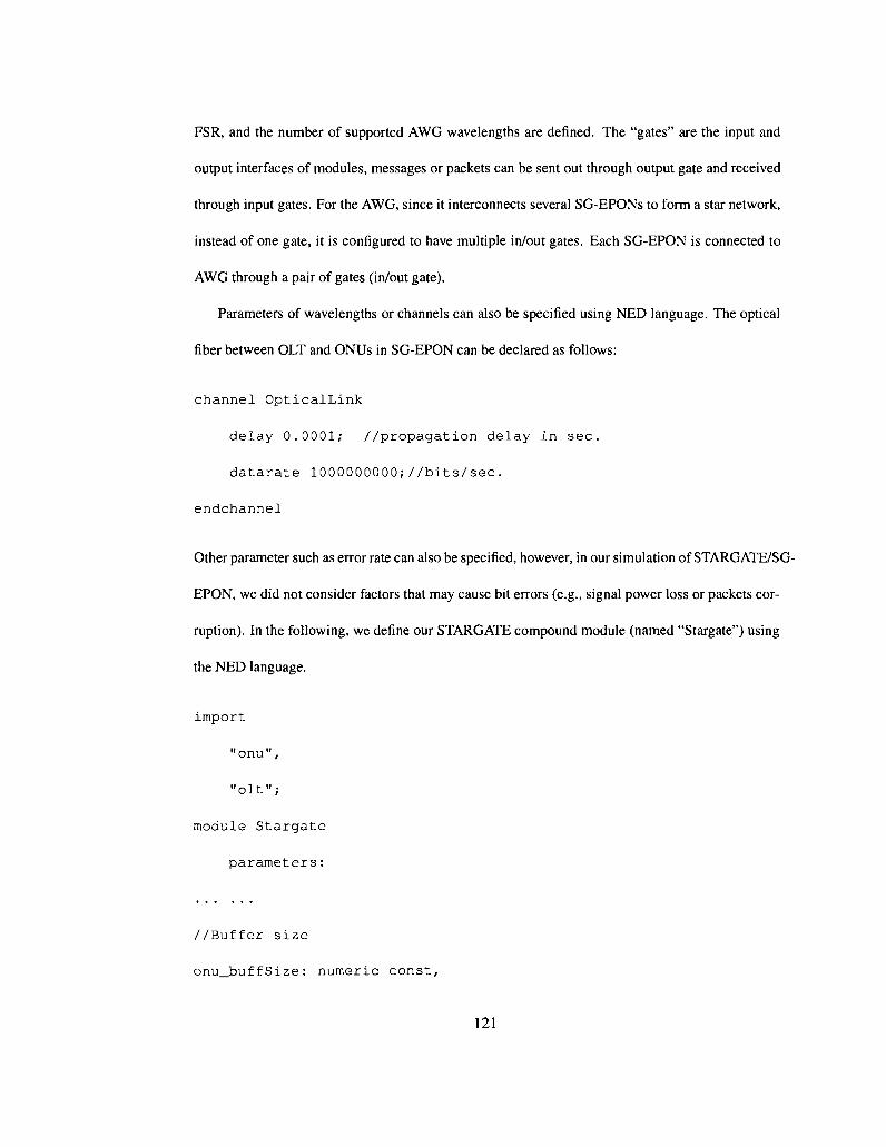
FSR, and the number of supported AWG wavelengths are defined. The "gates" are the input and
output interfaces of modules, messages or packets can be sent out through output gate and received
through input gates. For the AWG, since it interconnects several SG-EPONs to form a star network,
instead of one gate, it is configured to have multiple in/out gates. Each SG-EPON is connected to
AWG through a pair of gates (in/out gate).
Parameters of wavelengths or channels can also be specified using NED language. The optical
fiber between OLT and ONUs in SG-EPON can be declared as follows:
channel OpticalLink
delay 0.0001; //propagation delay in sec.
datarate 1000000000;//bits/sec.
endchannel
Other parameter such as error rate can also be specified, however, in our simulation of STARGATE/SG-
EPON, we did not consider factors that may cause bit errors (e.g., signal power loss or packets cor
ruption). In the following, we define our STARGATE compound module (named "Stargate") using
the NED language.
impor t
"onu" ,
"olt";
module Stargate
parameters:
//Buffer size
onu_buffSize: numeric const,
121

olt_buffSize: numeric const,
//Number of Ring-Star node
num_of_RSnode: numeric const,
//Number of Wavelength (WDM upstream/downstream, AWG)
num_of_Uwave: numeric const,
num_of_Dwave: numeric const,
num_of_Awave: numeric const,
//Data rate on different wavelengths (in bps)
dataRate_tdm: numeric const,
dataRate_wdm: numeric const,
dataRate_awg: numeric const,
dataRate_PSC: numeric const,
dataRate_RPR: numeric const,
The "import" section is pretty simple, it reads the .NED file in which OUT and ONU module have
been defined so that they can be nested in our STARGATE. Other parameters of STARGATE is
given in the "parameters" section. Here, only the data type of each parameter is declared, their
values can either be specified in the omnetpp.ini config file, or be typed in when the simulation is
initialized.
submodu les :
122
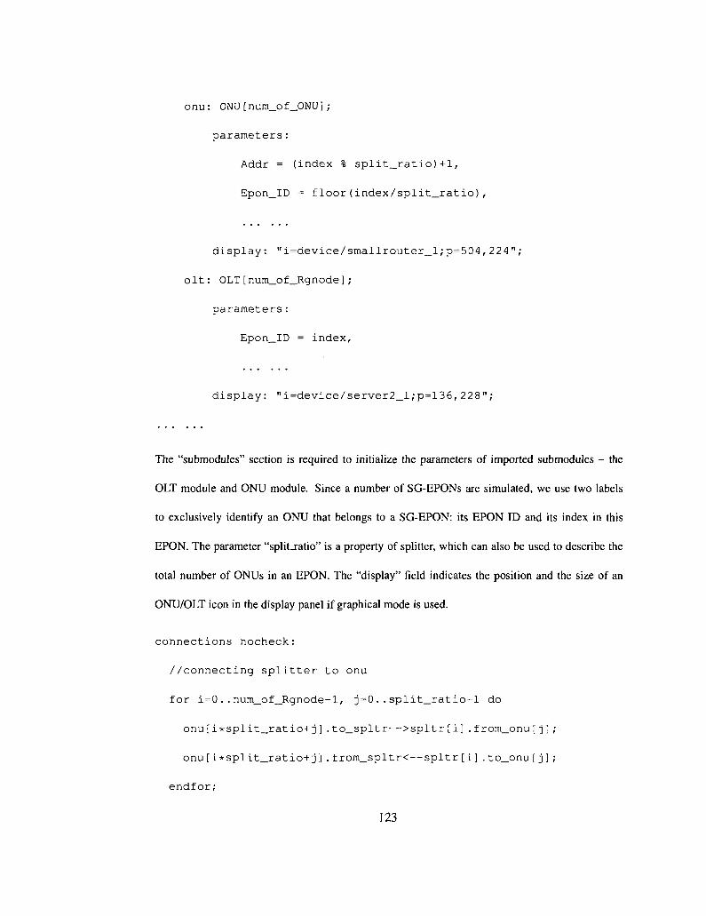
onu: ONU[num_of_ONU];
parameters:
Addr = (index % split_ratio)+1,
Epon_ID = floor(index/split_ratio),
display: "i=device/smallrouter_l;p=504,224";
olt: OLT[num_of_Rgnode];
parameters:
Epon_ID = index,
display: "i=device/server2_l;p=136,228";
The "submodules" section is required to initialize the parameters of imported submodules - the
OLT module and ONU module. Since a number of SG-EPONs are simulated, we use two labels
to exclusively identify an ONU that belongs to a SG-EPON: its EPON ID and its index in this
EPON. The parameter "split_ratio" is a property of splitter, which can also be used to describe the
total number of ONUs in an EPON. The "display" field indicates the position and the size of an
ONU/OLT icon in the display panel if graphical mode is used.
connections nocheck:
//connecting splitter to onu
for i=0..num_of_Rgnode-l, j=0..split_ratio-l do
onu[i*split_ratio+j].to_spltr—>spltr[i].from_onu[ j ] ;
onu[i*split_ratio+j].from_spltr<—spltr[i].to_onu[j];
endfor;
123
The above code describes the definition of connections between ONUs and the optical splitter in an
EPON. By default, NED requires that all gates be connected. Since this check can be inconvenient
at times, it can be turned off using the "nocheck" keyword.
After completing the structural construction of Stargate, the specific network elements defined
in NED file must be coded in C++. Most of what is in the NED file is part of the OMNet++
supporting library, and does not require any modification from the user. The gates, channels, channel
characteristics, connections, even the compound module Stargate, are taken care of by the OMNet++
library. Only the simple module should be implemented.
In fact, each simple module is nothing more than a C++ class which has to be subclassed from
cSimpleModule, with one or more virtual member functions redefined to define its behavior.
Note that the class has to be registered with OMNet++ via the Def ine_Module () macro.
Fundamentally, cSimpleModules exchange messages via their out/in gates. These messages
are of class type cMessage, which is already defined in OMNet++ library. It can be used to model
a number of things: events, messages, packets, frames, or signals traveling in a network. Some
already defined attributes of a message include: name, kind, length, bit error flag, and time stamp,
etc. If required, cMessage can be further redefined to support more properties.
Messages are sent from one module to another by calling send () family of functions. Another
variation of this function, s c h e d u l e A t ( ) , is used to send self-messages to a module itself. This
is due to some special needs, e.g., delaying certain action for some timeout period. Upon the arrival
of a message at a module (either normal messages or self-messages), the simulation engine calls the
hand l eMessage () function of this particular module. This is one of the two methods that users
are required to write their own code for different purposes. The other method i s i n i t i a l i z e ( ) , i t
performs all initialization tasks, such as read module parameters from omnetpp . i n i file, initialize
class variables, allocate dynamic data structures with new operator, or initialize and schedule events
124

with self-messages (timers). To sum up, four things should be done in C++1:
• cSimpleModule derived class definition.
• declare module in Def ine_Module () macro
• Implementation of the : : i n i t i a l i z e ( ) method.
• Implementation of the : : hand leMessage () method.
As an example, we present the our code for the buffer queue model, which is deployed at each
ONU to store generated packets.
// BufferQue.h //
•include <string.h>
•include <cstring>
•include "packet_m.h" //defines data packet
•include "report_m.h" //defines REPORT message
•include "selfmsg_m.h" //defines self-message
class BufferQue : public cSimpleModule
{
private:
int bufferSize;
cQueue* onu_Que; //For TDM/WDM upstream traffic
cQueue** onu_AWGQue; //For AWG upstream traffic
1 Although another function, finish() is provided to record results and statistics, its usage is optional.
125

//Vectors that record the results of simulation:
cOutVector onu_QueOccupancy;
cOutVector* onu_AwgQueOccupancy;
cOutVector onu_Que_DropRate;
cOutVector* onu_AwgQue_DropRate;
//this function records the simulation results
void updateVector(GenSelfMsg * msg) ;
protected:
virtual void initialize ();
virtual void handleMessage(cMessage *msg);
virtual void finish();
public:
BufferQue ();
virtual "BufferQue();
};
// End of BufferQue.h //
User defined member functions in BufferQue.h are implemented as shown in the following:
// BufferQue . cc //
tinclude <vector>
•include <omnetpp.h>
tinclude "bufferQue.h"
Define_Module(BufferQue);
using namespace std;
126

void BufferQue::initialize ()
{
//Reading buffer size from config file
bufferSize = par("bufferSize");
if ((strcmp(onuType, "TDM") == 0)
II (strcmp(onuType, "WDM"))
{
//this is a TDM/WDM ONU
onu_Que = new cQueue ();
onu_Que->setName("TDM/WDM Traffic Queue");
}
else if (strcmp(onuType, "LR") == 0)
{
//this is a LR ONU
onu_Que = new cQueue();
onu_Que->setName("TDM/WDM Traffic Queue");
onu_AWGQue = new cQueue* [num_of_AWGwave];
for (int id=0; id< num_of_AWGwave; id++)
onu_AWGQue[id]->setName("AWG Queue");
127

//Buffer Occupancy Vectors:
onu_QueOccupancy.setName("Queue Occupancy");
onu_Que_DropRate.setName("Drop Rate (Bytes)");
vectorTimer = new GenSelfMsg("Vector Timer",
VECTOR_TIMER_SELF);
scheduleAt(plot_interval, vectorTimer);
}
void BufferQue::handleMessage(cMessage *msg)
{
if (msg->kind() == AWG_DATA_PACKET)
{
//this queue is not full, insert the packet
if (bufUsed[queID]+msg->length()/8<bufferSize)
{
onu_AWGQue[quelD]->insert(msg);
bufUsed += msg->length()/8; //in bytes
return;
}
else
{
128

ev <<"AWG Queue Overflow!<<fullPath() << endl;
dropped_bytes[quelD] += (msg->length() / 8);
delete msg;
return;
}
}
else if (msg->kind() == TDM_DATA_PACKET)
{
}
else if (msg->kind() == WDM_DATA_PACKET)
{
}
else if (msg->kind() == VECTOR_TIMER_SELF)
{
updateVector(check_and_cast<GenSelfMsg*> (msg));
return;
}
}
// E n d o f BufferQue.cc //
In the simulation, self-messages are periodically sent by s c h e d u l e A t () function, therefore, the
statistic results are recorded based on the same time interval.
129