norme europÉenne europÄische norm … · 2018-03-07 · european standard norme europÉenne...
TRANSCRIPT

EUROPEAN STANDARD
NORME EUROPÉENNE
EUROPÄISCHE NORM
EN 12201-2
September 2011
ICS 23.040.20 Supersedes EN 12201-2:2003, EN 13244-2:2002
English Version
Plastics piping systems for water supply, and for drainage and sewerage under pressure - Polyethylene (PE) - Part 2: Pipes
Systèmes de canalisations en plastique pour l'alimentation en eau et pour les branchements et les collecteurs
d'assainissement avec pression - Polyéthylène (PE) - Partie 2: Tubes
Kunststoff-Rohrleitungssysteme für die Wasserversorgung und für Entwässerungs- und Abwasserdruckleitungen -
Polyethylen (PE) - Teil 2: Rohre
This European Standard was approved by CEN on 8 July 2011. CEN members are bound to comply with the CEN/CENELEC Internal Regulations which stipulate the conditions for giving this European Standard the status of a national standard without any alteration. Up-to-date lists and bibliographical references concerning such national standards may be obtained on application to the CEN-CENELEC Management Centre or to any CEN member. This European Standard exists in three official versions (English, French, German). A version in any other language made by translation under the responsibility of a CEN member into its own language and notified to the CEN-CENELEC Management Centre has the same status as the official versions. CEN members are the national standards bodies of Austria, Belgium, Bulgaria, Croatia, Cyprus, Czech Republic, Denmark, Estonia, Finland, France, Germany, Greece, Hungary, Iceland, Ireland, Italy, Latvia, Lithuania, Luxembourg, Malta, Netherlands, Norway, Poland, Portugal, Romania, Slovakia, Slovenia, Spain, Sweden, Switzerland and United Kingdom.
EUROPEAN COMMITTEE FOR STANDARDIZATION
C O M I T É E U R O P É E N D E N O R M A LI S A T I O N
EUR OP ÄIS C HES KOM ITEE FÜR NOR M UNG
Management Centre: Avenue Marnix 17, B-1000 Brussels
© 2011 CEN All rights of exploitation in any form and by any means reserved worldwide for CEN national Members.
Ref. No. EN 12201-2:2011: ELice
nsed
Cop
y: Q
ueen
s U
nive
rsity
Ath
ens,
The
Que
en's
Uni
vers
ity o
f Bel
fast
, 04/
02/2
012
19:2
9, U
ncon
trol
led
Cop
y, (
c) T
he B
ritis
h S
tand
ards
Inst
itutio
n 20
12

2
Contents
Foreword ................................................................................................................................................ 3!
Introduction ........................................................................................................................................... 5!
1! Scope .............................................................................................................................................. 6!
2! Normative references ................................................................................................................... 7!
3! Terms and definitions, symbols and abbreviations .................................................................. 7!
4! Material ........................................................................................................................................... 8!
4.1! Compound .................................................................................................................................. 8!
4.2! Compound for identification stripes ........................................................................................ 8!
5! General characteristics ................................................................................................................ 8!
5.1! Appearance ................................................................................................................................. 8!
5.2! Colour .......................................................................................................................................... 8!
5.3! Effect on water quality ............................................................................................................... 9!
6! Geometrical characteristics ......................................................................................................... 9!
6.1! Measurements ............................................................................................................................ 9!
6.2! Mean outside diameter, out-of-roundness (ovality) and tolerances ..................................... 9!
6.3! Wall thicknesses and their tolerances ................................................................................... 11!
6.4! Coiled pipe ................................................................................................................................ 14!
6.5! Pipe lengths .............................................................................................................................. 14!
7! Mechanical characteristics ........................................................................................................ 14!
7.1! Conditioning ............................................................................................................................. 14!
7.2! Requirements ........................................................................................................................... 14!
7.3! Retest in case of failure at 80 °C ............................................................................................ 16!
7.4! Pipe stiffness for vacuum sewer systems ............................................................................ 16!
8! Physical characteristics ............................................................................................................. 16!
8.1! Conditioning ............................................................................................................................. 16!
8.2! Requirements ........................................................................................................................... 16!
9! Chemical characteristics of pipes in contact with chemicals ................................................ 17!
10! Performance requirements ........................................................................................................ 17!
11! Marking......................................................................................................................................... 18!
11.1! General ...................................................................................................................................... 18!
11.2! Minimum required marking of pipes ...................................................................................... 18!
Annex A! (informative) Relationship between PN, MRS, S and SDR ........................................ 19!
Annex B! (normative) Pipes with co-extruded layers ................................................................. 20!
Annex C! (normative) Pipes with peelable layer ......................................................................... 22!
Annex D! (normative) Pipe stiffness for vacuum sewer systems ............................................. 24!
Bibliography ........................................................................................................................................ 26!
BS EN 12201-2:2011 EN 12201-2:2011 (E)
Lice
nsed
Cop
y: Q
ueen
s U
nive
rsity
Ath
ens,
The
Que
en's
Uni
vers
ity o
f Bel
fast
, 04/
02/2
012
19:2
9, U
ncon
trol
led
Cop
y, (
c) T
he B
ritis
h S
tand
ards
Inst
itutio
n 20
12
3
Foreword
This document (EN 12201-2:2011) has been prepared by Technical Committee CEN/TC 155 “Plastics piping systems and ducting systems”, the secretariat of which is held by NEN.
This European Standard shall be given the status of a national standard, either by publication of an identical text or by endorsement, at the latest by March 2012, and conflicting national standards shall be withdrawn at the latest by March 2012.
Attention is drawn to the possibility that some of the elements of this document may be the subject of patent rights. CEN [and/or CENELEC] shall not be held responsible for identifying any or all such patent rights.
This document supersedes EN 12201-2:2003, EN 13244-2:2002.
System Standards are based on the results of the work being undertaken in ISO/TC 138, "Plastics pipes, fittings and valves for the transport of fluids", which is a Technical Committee of the International Organization for Standardization (ISO).
They are supported by separate standards on test methods to which references are made throughout the System Standard.
The System Standards are consistent with general standards on functional requirements and on recommended practice for installation.
EN 12201 consists of the following parts:
EN 12201-1:, Plastics piping systems for water supply, and for drainage and sewerage under pressure — Polyethylene (PE) — Part 1: General;
EN 12201-2:, Plastics piping systems for water supply, and for drainage and sewerage under pressure — Polyethylene (PE) — Part 2: Pipes (this standard);
EN 12201-3:, Plastics piping systems for water supply, and for drainage and sewerage under pressure — Polyethylene (PE) — Part 3: Fittings;
EN 12201-4 , Plastics piping systems for water supply, and for drainage and sewerage under pressure — Polyethylene (PE) — Part 4: Valves for water supply systems;
EN 12201-5, Plastics piping systems for water supply, and for drainage and sewerage under pressure — Polyethylene (PE) — Part 5: Fitness for purpose of the system;
CEN/TS 12201-7, Plastics piping systems for water supply — Polyethylene (PE) — Part 7: Guidance for the assessment of conformity.
In this revision, the scope of this standard includes two additional types of pipe;-
PE pipes with co-extruded layers on either or both the outside and/or inside of the pipe as specified in Annex B, where all layers have the same MRS rating;
PE pipes with a peelable, contiguous thermoplastics additional layer on the outside of the pipe (‘coated pipe’) as specified in Annex C.
In this revision, pipe diameters specified have been increased to 2500 mm. Test methods have been updated as appropriate and in accordance with other parts of this standard.
BS EN 12201-2:2011 EN 12201-2:2011 (E)
Lice
nsed
Cop
y: Q
ueen
s U
nive
rsity
Ath
ens,
The
Que
en's
Uni
vers
ity o
f Bel
fast
, 04/
02/2
012
19:2
9, U
ncon
trol
led
Cop
y, (
c) T
he B
ritis
h S
tand
ards
Inst
itutio
n 20
12

4
According to the CEN/CENELEC Internal Regulations, the national standards organizations of the following countries are bound to implement this European Standard: Austria, Belgium, Bulgaria, Croatia, Cyprus, Czech Republic, Denmark, Estonia, Finland, France, Germany, Greece, Hungary, Iceland, Ireland, Italy, Latvia, Lithuania, Luxembourg, Malta, Netherlands, Norway, Poland, Portugal, Romania, Slovakia, Slovenia, Spain, Sweden, Switzerland and the United Kingdom.
BS EN 12201-2:2011 EN 12201-2:2011 (E)
Lice
nsed
Cop
y: Q
ueen
s U
nive
rsity
Ath
ens,
The
Que
en's
Uni
vers
ity o
f Bel
fast
, 04/
02/2
012
19:2
9, U
ncon
trol
led
Cop
y, (
c) T
he B
ritis
h S
tand
ards
Inst
itutio
n 20
12

5
Introduction
The System Standard, of which this is Part 2, specifies the requirements for a piping system and its components when made from polyethylene (PE). The piping system is intended to be used for water supply intended for human consumption, including the conveyance of raw water prior to treatment, drainage and sewerage under pressure, vacuum sewer systems, and water for other purposes.
In respect of potential adverse effects on the quality of water intended for human consumption, caused by the product covered by EN 12201 (all parts):
a) this standard provides no information as to whether the product may be used without restriction in any of the Member States of the EU or EFTA;
b) products intended for use in water supply systems must comply, when existing, with national regulations and testing arrangements that ensure fitness for contact with drinking water.
NOTE On April 2006, EC Commission set up a revised mandate (M/136) asking CEN to propose harmonised product standards and support standards for test methods which could be used for assessing the fitness for contact with drinking water. In parallel, EC Commission has launched processes for a regulation of construction products (CPR) to be substituted to CP directive (89/106/EEC) and for the revision of drinking water directive (98/83/EC). If relevant, when the outputs of these processes will be known, European Product Standards will be amended by the addition of an Annex Z under Mandate M136, which will contain formal references to the applicable requirements. Until such amendments, the current national regulations remain applicable.
Requirements and test methods for material and components, other than pipes, are specified in EN 12201-1:2011, EN 12201-3:2011 [1] and prEN 12201-4:2011 [2].
Characteristics for fitness of purpose are covered in EN 12201-5:2011 and CEN/TS 12201-7 [3] gives guidance for the assessment of conformity.
This Part of EN 12201 covers the characteristics of pipes.
BS EN 12201-2:2011 EN 12201-2:2011 (E)
Lice
nsed
Cop
y: Q
ueen
s U
nive
rsity
Ath
ens,
The
Que
en's
Uni
vers
ity o
f Bel
fast
, 04/
02/2
012
19:2
9, U
ncon
trol
led
Cop
y, (
c) T
he B
ritis
h S
tand
ards
Inst
itutio
n 20
12

6
1 Scope
This part of EN 12201 specifies the characteristics of pipes made from polyethylene (PE 100, PE 80 and PE 40) for buried and above ground applications, intended for the conveyance of water for human consumption, raw water prior to treatment, drainage and sewerage under pressure, vacuum sewer systems, and water for other purposes.
NOTE 1 For PE components intended for the conveyance of water for human consumption and raw water prior to treatment attention is drawn to 5.3 of this European Standard. Components manufactured for water for general purposes, drainage and sewerage may not be suitable for water supply for human consumption.
It also specifies the test parameters for the test methods referred to in this standard.
In conjunction with Part 1 and Parts 3 to 5 of EN 12201, it is applicable to PE pipes, their joints and to joints with components of PE and other materials intended to be used under the following conditions:
a) allowable operating pressure, PFA, up to 25 bar 1);
b) an operating temperature of 20 °C as a reference temperature;
c) buried in the ground;
d) sea outfalls;
e) laid in water;
f) above ground, including pipes suspended below bridges.
NOTE 2 For applications operating at constant temperatures greater than 20 °C and up to 40 °C, see Annex A of EN 12201-1:2011.
NOTE 3 Pipes constructions including barrier layers are not covered by this document.
EN 12201 covers a range of allowable operating pressures and gives requirements concerning colours and additives.
It covers three types of pipe:
PE pipes (outside diameter dn) including any identification stripes;
PE pipes with co-extruded layers on either or both the outside and/or inside of the pipe (total outside diameter
dn) as specified in Annex B, where all layers have the same MRS rating;
PE pipes (outside diameter dn) with a peelable, contiguous thermoplastics additional layer on the outside of the
pipe (‘coated pipe’) as specified in Annex C.
NOTE 4 It is the responsibility of the purchaser or specifier to make the appropriate selections from these aspects, taking into account their particular requirements and any relevant national guidance or regulations and installation practices or codes.
NOTE 5 Assessment of the resistance to slow crack growth of the PE pipe compound used for the manufacture of products to this document is required in accordance with Table 2 of EN 12201-1:2011.
1) 1 bar = 0,1 MPa = 105 Pa; 1 MPa = 1 N/mm2.
BS EN 12201-2:2011 EN 12201-2:2011 (E)
Lice
nsed
Cop
y: Q
ueen
s U
nive
rsity
Ath
ens,
The
Que
en's
Uni
vers
ity o
f Bel
fast
, 04/
02/2
012
19:2
9, U
ncon
trol
led
Cop
y, (
c) T
he B
ritis
h S
tand
ards
Inst
itutio
n 20
12

7
2 Normative references
The following referenced documents are indispensable for the application of this document. For dated references, only the edition cited applies. For undated references, the latest edition of the referenced document (including any amendments) applies.
EN 12201-1:2011, Plastics piping systems for water supply, and for drainage and sewerage under pressure — Polyethylene (PE) — Part 1: General
EN 12201-5, Plastics piping systems for water supply, and for drainage and sewerage under pressure — Polyethylene (PE) — Part 5: Fitness for purpose of the system
CEN/TR 15438, Plastics piping systems – Guidance for coding of products and their intended uses
EN ISO 1133, Plastics — Determination of the melt mass-flow rate (MFR) and the melt volume-flow rate (MVR) of thermoplastics (ISO 1133:2005)
EN ISO 1167-1, Thermoplastics pipes, fittings and assemblies for the conveyance of fluids — Determination of the resistance to internal pressure — Part 1: General method (ISO 1167-1:2006)
EN ISO 1167-2, Thermoplastics pipes, fittings and assemblies for the conveyance of fluids — Determination of the resistance to internal pressure — Part 2: Preparation of pipe test pieces (ISO 1167-2:2006)
EN ISO 2505, Thermoplastics pipes – Rongitudinal reversion – Test method and parameters (ISO 2505:2005)
EN ISO 3126, Plastics piping systems — Plastics components — Determination of dimensions (ISO 3126:2005)
EN ISO 6259-1, Thermoplastics pipes — Determination of tensile properties — Part 1: General test method (ISO 6259-1:1997)
EN ISO 9969, Thermoplastics pipes — Determination of ring stiffness (ISO 9969:2007)
EN ISO 13968, Plastics piping and ducting systems !—Thermoplastics pipes !— Determination of ring flexibility (ISO 13968:2008)
ISO 4433-1:1997, Thermoplastics pipes — Resistance to liquid chemicals — Classification — Part 1: Immersion test method
ISO 4433-2:1997, Thermoplastics pipes — Resistance to liquid chemicals — Classification — Part 2: Polyolefin pipes
ISO 6259-3:1997, Thermoplastics pipes — Determination of tensile properties — Part 3: Polyolefin pipes
ISO 11357-6, Plastics — Differential scanning calorimetry (DSC) — Part 6: Determination of oxidation induction time (isothermal OIT) and oxidation induction temperature (dynamic OIT)
3 Terms and definitions, symbols and abbreviations
For the purposes of this document, the terms and definitions, symbols and abbreviations given in EN 12201-1 apply.
BS EN 12201-2:2011 EN 12201-2:2011 (E)
Lice
nsed
Cop
y: Q
ueen
s U
nive
rsity
Ath
ens,
The
Que
en's
Uni
vers
ity o
f Bel
fast
, 04/
02/2
012
19:2
9, U
ncon
trol
led
Cop
y, (
c) T
he B
ritis
h S
tand
ards
Inst
itutio
n 20
12

8
4 Material
4.1 Compound
The pipes shall be made from virgin material or own reprocessable material from the same PE compound or a mixture of both materials. Reprocessable material from pipes reprocessed with the peelable layer attached shall not be used. Own reprocessed material from the base pipe of peelable layer pipes can be used. For information on reprocessed material from coextruded pipe see B.1.
The compound(s) from which the pipes are made shall conform to EN 12201-1.
4.2 Compound for identification stripes
For black pipe with identification stripes (see 5.2), the compound used for these identification stripes shall be made from the same base polymer (PE) as one of the pipe compounds for which fusion compatibility has been proven.
5 General characteristics
5.1 Appearance
When viewed without magnification the internal and external surfaces of pipes shall be smooth and clean and shall have no scoring, cavities, and other surface defects to an extent that would prevent conformity to this standard.
The ends of the pipe shall be cut cleanly and square to the axis of the pipe.
5.2 Colour
Pipes intended for the conveyance of water for human consumption shall be black or blue. In addition, black pipes may be identified by blue stripes, according to national preference.
Blue pipes or black pipes with blue stripes are intended for the conveyance of water for human consumption only.
Pipes intended for other purposes, drainage and sewerage shall be black or black with brown stripes or according to national preference.
The outer coextruded layer of coextruded pipes (see Annex B) or the outer peelable layer of peelable layer pipes (see Annex C) for pipe intended for the conveyance of water for human consumption shall be either black or blue. In addition identification stripes may be used according to national preference for the application.
The outer coextruded layer of coextruded pipes (see Annex B) or the outer peelable layer of peelable layer pipes (see Annex C) for pipe intended for other purposes shall be either black or black with brown stripes or brown or according to national preference. In addition identification stripes of a different colour may be used according to national preference for the application.
NOTE 1 In some countries, pipes made from non-pigmented compound in conjunction with an external peelable layer are permitted, providing the compound conforms to the requirements of this standard. If this is allowed in a country, this should be clearly stated in the national foreword.
NOTE 2 For above ground installations, all components other than black should be protected from direct UV light.
NOTE 3 The national preference for colour should be stated in the National Foreword.
BS EN 12201-2:2011 EN 12201-2:2011 (E)
Lice
nsed
Cop
y: Q
ueen
s U
nive
rsity
Ath
ens,
The
Que
en's
Uni
vers
ity o
f Bel
fast
, 04/
02/2
012
19:2
9, U
ncon
trol
led
Cop
y, (
c) T
he B
ritis
h S
tand
ards
Inst
itutio
n 20
12

9
5.3 Effect on water quality
For compounds intended to be used for components in contact with water for human consumption, attention is drawn to the requirements of national regulations.
6 Geometrical characteristics
6.1 Measurements
The dimensions of the pipe shall be measured in accordance with EN ISO 3126 and rounded to the next 0,1 mm. In the case of dispute the measurements of dimensions shall be made not less than 24 h after manufacture after
being conditioned for at least 4 h at (23 ± 2) °C.
NOTE 1 Indirect measurement during the stage of production is allowed at shorter time periods providing evidence is shown of correlation.
NOTE 2 The national preference for pipe size and PN rating may be given in the National Foreword.
6.2 Mean outside diameter, out-of-roundness (ovality) and tolerances
The mean outside diameters, dem, and the out-of-roundness (ovality) shall be in accordance with Table 1. For
coiled pipes, the maximum out-of roundness shall be specified by agreement between the manufacturer and the end-user.
Pipe extruded from PE 40 materials shall be limited to diameters up to and including 63 mm.
NOTE 1 In some countries pipe in PE 40 materials may be used in diameters up to and including 90 mm. If this is the case this should be stated in the National Foreword.
BS EN 12201-2:2011 EN 12201-2:2011 (E)
Lice
nsed
Cop
y: Q
ueen
s U
nive
rsity
Ath
ens,
The
Que
en's
Uni
vers
ity o
f Bel
fast
, 04/
02/2
012
19:2
9, U
ncon
trol
led
Cop
y, (
c) T
he B
ritis
h S
tand
ards
Inst
itutio
n 20
12

10
Table 1 — Mean outside diameters and out-of-roundness
Dimensions in millimetres
Nominal size
DN/OD
Nominal outside
diameter Mean outside diameter a Maximum out-of-
roundness (ovality) b,d dn dem,min dem,max
16
20
25
32
40
50
63
75
90
110
125
140
160
180
200
225
250
280
315
355
400
450
500
560
630
710
800
900
1 000
1 200
1 400
1 600
1 800
2 000
2 250
2 500
16
20
25
32
40
50
63
75
90
110
125
140
160
180
200
225
250
280
315
355
400
450
500
560
630
710
800
900
1 000
1 200
1 400
1 600
1 800
2 000
2 250
2 500
16,0
20,0
25,0
32,0
40,0
50,0
63,0
75,0
90,0
110,0
125,0
140,0
160,0
180,0
200,0
225,0
250,0
280,0
315,0
355,0
400,0
450,0
500,0
560,0
630,0
710,0
800,0
900,0
1 000,0
1 200,0
1 400,0
1 600,0
1 800,0
2 000,0
2 250,0
2 500,0
16,3
20,3
25,3
32,3
40,4
50,4
63,4
75,5
90,6
110,7
125,8
140,9
161,0
181,1
201,2
226,4
251,5
281,7
316,9
357,2
402,4
452,7
503,0
563,4
633,8
716,4
807,2
908,1
1 009,0
1 210,8 c
1 412,6 c
1 614,4 c
1 816,2 c
2 018,0 c
2270,3 c
2522,5 c
1,2
1,2
1,2
1,3
1,4
1,4
1,5
1,6
1,8
2,2
2,5
2,8
3,2
3,6
4,0
4,5
5,0
9,8
11,1
12,5
14,0
15,6
17,5
19,6
22,1
24,9
28,0
—
—
—
—
—
—
—
—
— a In accordance with ISO 11922-1:1997 [7] grade B for sizes ≤ 630 and grade A for sizes > 710 except for dn 40 and
50. b In accordance with ISO 11922-1:1997 [7] grade N for sizes ≤ 630 and is measured at the point of manufacture.
c Tolerance calculated as 0,009dn and does not conform to grade A in ISO 11922-1:1997 [7].
d For straight lengths of pipe with diameters ≥ 900 the maximum out-of-roundness shall be agreed between the
manufacturer and the purchaser.
NOTE 2 Tolerance bands in accordance with ISO 11922-1:1997 [7] are calculated using the following formulae, as applicable.
a) Grade A: 0,009dn rounded to the next greater 0,1 mm with a minimum value of 0,3 mm and a maximum value of 10,0 mm;
b) Grade B: 0,006dn rounded up to the next greater 0,1 mm with a minimum value of 0,3 mm and a maximum value of 4,0 mm;
c) Grade N:
BS EN 12201-2:2011 EN 12201-2:2011 (E)
Lice
nsed
Cop
y: Q
ueen
s U
nive
rsity
Ath
ens,
The
Que
en's
Uni
vers
ity o
f Bel
fast
, 04/
02/2
012
19:2
9, U
ncon
trol
led
Cop
y, (
c) T
he B
ritis
h S
tand
ards
Inst
itutio
n 20
12

11
for diameters ≤ 75 mm: (0,008dn + 1) mm;
for diameters ≥ 90 mm and ≤ 250 mm: (0,02dn) mm;
for diameters > 250 mm: (0,035dn) mm,
rounded to next greater 0,1 mm.
6.3 Wall thicknesses and their tolerances
The wall thickness shall be in accordance with Table 2.
NOTE 1 The relationship between PN, MRS, S and SDR is given in Table A.1.
BS EN 12201-2:2011 EN 12201-2:2011 (E)
Lice
nsed
Cop
y: Q
ueen
s U
nive
rsity
Ath
ens,
The
Que
en's
Uni
vers
ity o
f Bel
fast
, 04/
02/2
012
19:2
9, U
ncon
trol
led
Cop
y, (
c) T
he B
ritis
h S
tand
ards
Inst
itutio
n 20
12

12
Table 2 — Wall thicknesses
Dimensions in millimetres
Pipe series
SDR 6 SDR 7,4 SDR 9 SDR 11 SDR 13,6 SDR 17
S 2,5 S 3,2 S 4 S 5 S 6,3 S 8
Nominal pressure, PN a in bar
PE 40 — PN 10 — PN 6 — PN 4
PE 80 PN 25 PN 20 PN 16 PN 12,5 PN 10 PN 8
PE 100 — PN 25 PN 20 PN 16 PN 12,5 PN 10
Nom.
size
DN/OD
Wall thicknesses b
emin emax emin emax emin emax emin emax emin emax emin emax
16
20
25
32
40
50
63
75
90
110
125
140
160
180
200
225
250
280
315
355
400
450
500
560
630
710
800
900
1000
1200
1400
1600
1800
2000
3,0 c
3,4
4,2
5,4
6,7
8,3
10,5
12,5
15,0
18,3
20,8
23,3
26,6
29,9
33,2
37,4
41,5
46,5
52,3
59,0
-
-
-
-
-
-
-
-
-
-
-
-
-
-
3,4
3,9
4,8
6,1
7,5
9,3
11,7
13,9
16,7
20,3
23,0
25,8
29,4
33,0
36,7
41,3
45,8
51,3
57,7
65,0
-
-
-
-
-
-
-
-
-
-
-
-
-
-
2,3 c
3,0 c
3,5
4,4
5,5
6,9
8,6
10,3
12,3
15,1
17,1
19,2
21,9
24,6
27,4
30,8
34,2
38,3
43,1
48,5
54,7
61,5
-
-
-
-
-
-
-
-
-
-
-
-
2,7
3,4
4,0
5,0
6,2
7,7
9,6
11,5
13,7
16,8
19,0
21,3
24,2
27,2
30,3
34,0
37,8
42,3
47,6
53,5
60,3
67,8
-
-
-
-
-
-
-
-
-
-
-
-
2,0 c
2,3
3,0 c
3,6
4,5
5,6
7,1
8,4
10,1
12,3
14,0
15,7
17,9
20,1
22,4
25,2
27,9
31,3
35,2
39,7
44,7
50,3
55,8
62,5
70,3
79,3
89,3
-
-
-
-
-
-
-
2,3
2,7
3,4
4,1
5,1
6,3
8,0
9,4
11,3
13,7
15,6
17,4
19,8
22,3
24,8
27,9
30,8
34,6
38,9
43,8
49,3
55,5
61,5
68,9
77,5
87,4
98,4
-
-
-
-
-
-
-
-
2,0 c
2,3
3,0 c
3,7
4,6
5,8
6,8
8,2
10,0
11,4
12,7
14,6
16,4
18,2
20,5
22,7
25,4
28,6
32,2
36,3
40,9
45,4
50,8
57,2
64,5
72,6
81,7
90,8
-
-
-
-
-
-
2,3
2,7
3,4
4,2
5,2
6,5
7,6
9,2
11,1
12,7
14,1
16,2
18,2
20,2
22,7
25,1
28,1
31,6
35,6
40,1
45,1
50,1
56,0
63,1
71,1
80,0
90,0
100,0
-
-
-
-
-
-
-
2,0 c
2,4
3,0
3,7
4,7
5,6
6,7
8,1
9,2
10,3
11,8
13,3
14,7
16,6
18,4
20,6
23,2
26,1
29,4
33,1
36,8
41,2
46,3
52,2
58,8
66,1
73,4
88,2
102,9
117,5
-
-
-
-
2,3
2,8
3,5
4,2
5,3
6,3
7,5
9,1
10,3
11,5
13,1
14,8
16,3
18,4
20,4
22,8
25,7
28,9
32,5
36,6
40,6
45,5
51,1
57,6
64,8
72,9
80,9
97,2
113,3
129,4
-
-
-
-
-
2,0 c
2,4
3,0
3,8
4,5
5,4
6,6
7,4
8,3
9,5
10,7
11,9
13,4
14,8
16,6
18,7
21,1
23,7
26,7
29,7
33,2
37,4
42,1
47,4
53,3
59,3
71,1
83,0
94,84
106,6
118,4
-
-
-
2,3
2,8
3,4
4,3
5,1
6,1
7,4
8,3
9,3
10,6
11,9
13,2
14,9
16,4
18,4
20,7
23,4
26,2
29,5
32,8
36,7
41,3
46,5
52,3
58,8
65,4
78,4
91,5
104,4
117,4
130,4 a PN values are based on C = 1,25. b Tolerances in accordance with grade V of ISO 11922-1:1997 [7]. c The calculated value of emin. (ISO 4065:1996 [5]) is rounded up to the nearest value of either 2,0, 2,3 or 3,0. This is to satisfy
certain national requirements.
BS EN 12201-2:2011 EN 12201-2:2011 (E)
Lice
nsed
Cop
y: Q
ueen
s U
nive
rsity
Ath
ens,
The
Que
en's
Uni
vers
ity o
f Bel
fast
, 04/
02/2
012
19:2
9, U
ncon
trol
led
Cop
y, (
c) T
he B
ritis
h S
tand
ards
Inst
itutio
n 20
12

13
Table 2 — Wall thicknesses (continued)
Dimensions in millimetres
Pipe series
SDR 21 SDR26 SDR 33 SDR 41
S 10 S 12,5 S 16 S 20
Nominal pressure, PN a in bar
PE 40 — — — —
PE 80 PN 6 PN 5 PN 4 PN 3,2
PE 100 PN 8 PN 6 PN 5 PN 4
Nom.
size
DN/OD
Wall thicknesses b!
emin emax emin emax emin emax emin emax
16
20
25
32
40
50
63
75
90
110
125
140
160
180
200
225
250
280
315
355
400
450
500
560
630
710
800
900
1000
1200
1400
1600
1800
2000
2250
2500
-
-
-
-
2,0 c
2,4
3,0
3,6
4,3
5,3
6,0
6,7
7,7
8,6
9,6
10,8
11,9
13,4
15,0
16,9
19,1
21,5
23,9
26,7
30,0
33,9
38,1
42,9
47,7
57,2
66,7
76,2
85,8
95,3
107,2
119,1
-
-
-
-
2,3
2,8
3,4
4,1
4,9
6,0
6,7
7,5
8,6
9,6
10,7
12,0
13,2
14,9
16,6
18,7
21,2
23,8
26,4
29,5
33,1
37,4
42,1
47,3
52,6
63,1
73,5
84,0
94,5
105,0
118,1
131,2
-
-
-
-
-
2,0
2,5
2,9
3,5
4,2
4,8
5,4
6,2
6,9
7,7
8,6
9,6
10,7
12,1
13,6
15,3
17,2
19,1
21,4
24,1
27,2
30,6
34,4
38,2
45,9
53,5
61,2
68,8
76,4
86,0
95,6
-
-
-
-
-
2,3
2,9
3,3
4,0
4,8
5,4
6,1
7,0
7,7
8,6
9,6
10,7
11,9
13,5
15,1
17,0
19,1
21,2
23,7
26,7
30,1
33,8
38,3
42,2
50,6
59,0
67,5
75,8
84,2
94,8
105,2
-
-
-
-
-
-
-
-
-
-
-
-
-
-
-
-
-
-
9,7
10,9
12,3
13,8
15,3
17,2
19,3
21,8
24,5
27,6
30,6
36,7
42,9
49,0
55,1
61,2
70,0
77,7
-
-
-
-
-
-
-
-
-
-
-
-
-
-
-
-
-
-
10,8
12,1
13,7
15,3
17,0
19,1
21,4
24,1
27,1
30,5
33,5
40,5
47,3
54,0
60,8
67,5
77,2
85,6
-
-
-
-
-
-
-
-
-
-
-
-
-
-
-
-
-
-
7,7
8,7
9,8
11,0
12,3
13,7
15,4
17,4
19,6
22,0
24,5
29,4
34,3
39,2
44,0
48,9
55,0
61,2
-
-
-
-
-
-
-
-
-
-
-
-
-
-
-
-
-
-
8,6
9,7
10,9
12,2
13,7
15,2
17,1
19,3
21,7
24,3
27,1
32,5
37,9
43,3
48,6
53,9
60,7
67,5 a PN values are based on C = 1,25.
b Tolerances in accordance with grade V of ISO 11922-1:1997 [7].
c The calculated value of emin. (ISO 4065:1996 [5]) is rounded up to the nearest value of
either 2,0, 2,3 or 3,0. This is to satisfy certain national requirements.
NOTE 2 Grade V tolerances are in accordance with ISO 11922-1:1997 [7] and calculated from the following formula:
BS EN 12201-2:2011 EN 12201-2:2011 (E)
Lice
nsed
Cop
y: Q
ueen
s U
nive
rsity
Ath
ens,
The
Que
en's
Uni
vers
ity o
f Bel
fast
, 04/
02/2
012
19:2
9, U
ncon
trol
led
Cop
y, (
c) T
he B
ritis
h S
tand
ards
Inst
itutio
n 20
12

14
(0,1emin + 0,1) mm, rounded to the next 0,1 mm higher.
For certain applications en > 30 mm tolerance grade T in accordance with ISO 11922-1:1997 [7] can be used and
the tolerance calculated from the following formula: 0,15emin, rounded to next higher 0,1 mm.
6.4 Coiled pipe
During production the pipe shall be coiled such that localised deformation, e.g. buckling and kinking, is prevented.
The minimum internal diameter of the coil shall be not less than 18dn.
NOTE If smaller coil diameters are necessary, they shall be agreed between the manufacturer and the end user.
6.5 Pipe lengths
No requirements have been set concerning particular lengths of coiled or straight pipe or the tolerance thereon; hence it is necessary for lengths of pipe to be supplied by agreement between purchaser and manufacturer.
7 Mechanical characteristics
7.1 Conditioning
Unless otherwise specified by the applicable test method, the test pieces shall be conditioned at (23 ± 2) °C before testing in accordance with Table 3.
7.2 Requirements
When tested in accordance with the test method as specified in Table 3 using the indicated parameters, the pipe shall have mechanical characteristics conforming to the requirements given in Table 3.
BS EN 12201-2:2011 EN 12201-2:2011 (E)
Lice
nsed
Cop
y: Q
ueen
s U
nive
rsity
Ath
ens,
The
Que
en's
Uni
vers
ity o
f Bel
fast
, 04/
02/2
012
19:2
9, U
ncon
trol
led
Cop
y, (
c) T
he B
ritis
h S
tand
ards
Inst
itutio
n 20
12

15
Table 3 — Mechanical characteristics
Characteristics Requirements Test parameters
Test method Parameters Value
Hydrostatic
strength at 20 °C
No failure during
test period of any
test pieces
End caps
Conditioning period
Number of test pieces b
Type of test
Test temperature
Test period
Circumferential (hoop) stress
for:
PE 40
PE 80
PE 100
Type A a
Shall conform to
EN ISO 1167-1
3
Water-in-water
20 °C
100 h
7,0 MPa
10,0 MPa
12,0 MPa
EN ISO 1167-1 and
EN ISO 1167-2
Hydrostatic
strength at 80 °C
No failure during
test period of any
test pieces
End caps
Conditioning period
Number of test pieces b
Type of test
Test temperature
Test period
Circumferential (hoop) stress
for:
PE 40
PE 80
PE 100
Type A a
Shall conform to
EN ISO 1167-1
3
Water-in-water
80 °C
165 h c
2,5 MPa
4,5 MPa
5,4 MPa
EN ISO 1167-1 and
EN ISO 1167-2
Hydrostatic
strength at 80 °C
No failure during
test period of any
test pieces
End caps
Conditioning period
Number of test pieces b
Type of test
Test temperature
Test period
Circumferential (hoop) stress
for:
PE 40
PE 80
PE 100
Type A a
Shall conform to
EN ISO 1167-1
3
Water-in-water
80 °C
1000 h
2,0 MPa
4,0 MPa
5,0 MPa
EN ISO 1167-1 and
EN ISO 1167-2
Elongation at
break for
en ≤ 5 mm
≥ 350 % Test piece shape
Speed of test
Number of test pieces b
Type 2
100 mm/min
Shall conform to
EN ISO 6259-1
EN ISO 6259-1 and
ISO 6259-3:1997
Elongation at
break for
5 mm < en ≤ 12
mm
≥ 350 % Test piece shape
Speed of test
Number of test pieces b
Type 1 d
50 mm/min
Shall conform to
EN ISO 6259-1
EN ISO 6259-1 and
ISO 6259-3:1997
Elongation at
break for
en > 12 mm
≥ 350 % Test piece shape
Speed of test
Number of test pieces b
Type 1 d
25 mm/min
Shall conform to
EN ISO 6259-1:
EN ISO 6259-1 and
ISO 6259-3:1997
OR
Test piece shape
Speed of test
Number of test pieces b
Type 3 d
10 mm/min
Shall conform to
EN ISO 6259-1
BS EN 12201-2:2011 EN 12201-2:2011 (E)
Lice
nsed
Cop
y: Q
ueen
s U
nive
rsity
Ath
ens,
The
Que
en's
Uni
vers
ity o
f Bel
fast
, 04/
02/2
012
19:2
9, U
ncon
trol
led
Cop
y, (
c) T
he B
ritis
h S
tand
ards
Inst
itutio
n 20
12

16
a Type B end caps may be used for batch release tests for diameters ≥ 500 mm.
b The number of test pieces given indicate the quantity required to establish a value for the characteristic described in the table. The
number of test pieces required for factory production control and process control should be listed in the manufacturer’s quality plan (for
guidance see CEN/TS 12201-7 [3]). c Premature ductile failures are not taken into account. For retest procedure see 7.3.
d Machined type 2 test pieces may be used for pipe wall thicknesses ≤ 25 mm. The test may be terminated when the requirement is met,
without continuing until the rupture of the test piece.
7.3 Retest in case of failure at 80 °C
A fracture in a brittle mode in less than 165 h shall constitute a failure; however if a sample in the 165 h test fails in a ductile mode in less than 165 h, a retest shall be performed at a selected lower stress in order to achieve the minimum required time for the selected stress obtained from the line through the stress/time points given in Table 4.
Table 4 — Test parameters for the retest of the hydrostatic strength at 80 °C
PE 40 PE 80 PE 100
Stress Test period Stress Test period Stress Test period
MPa h MPa h MPa h
2,5 165 4,5 165 5,4 165
2,4 230 4,4 233 5,3 256
2,3 323 4,3 331 5,2 399
2,2 463 4,2 474 5,1 629
2,1 675 4,1 685 5,0 1 000
2,0 1 000 4,0 1 000
7.4 Pipe stiffness for vacuum sewer systems
Pipes for use in vacuum sewer systems shall have an initial ring stiffness Scalc ≥ 4. See Annex D.
8 Physical characteristics
8.1 Conditioning
Unless otherwise specified by the applicable test method, the test pieces shall be conditioned at (23 ± 2) °C before testing in accordance with Table 5.
8.2 Requirements
When tested in accordance with the test methods as specified in Table 5 using the indicated parameters, the pipe shall have physical characteristics conforming to the requirements given in Table 5.
BS EN 12201-2:2011 EN 12201-2:2011 (E)
Lice
nsed
Cop
y: Q
ueen
s U
nive
rsity
Ath
ens,
The
Que
en's
Uni
vers
ity o
f Bel
fast
, 04/
02/2
012
19:2
9, U
ncon
trol
led
Cop
y, (
c) T
he B
ritis
h S
tand
ards
Inst
itutio
n 20
12
17
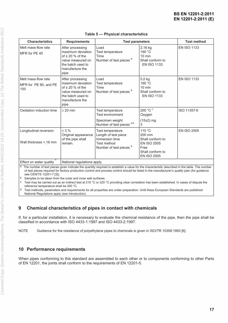
Table 5 — Physical characteristics
Characteristics Requirements Test parameters Test method
Melt mass-flow rate
MFR for PE 40
After processing
maximum deviation
of ± 20 % of the
value measured on
the batch used to
manufacture the
pipe
Load
Test temperature
Time
Number of test pieces a
2,16 kg
190 °C
10 min
Shall conform to
EN ISO 1133
EN ISO 1133
Melt mass-flow rate
MFR for PE 80, and PE
100
After processing
maximum deviation
of ± 20 % of the
value measured on
the batch used to
manufacture the
pipe
Load
Test temperature
Time
Number of test pieces a
5,0 kg
190 °C
10 min
Shall conform to
EN ISO 1133
EN ISO 1133
Oxidation induction time ≥ 20 min Test temperature
Test environment
Specimen weight
Number of test pieces a,b
200 °C c
Oxygen
(15±2) mg
3
ISO 11357-6
Longitudinal reversion
Wall thickness < 16 mm
≤ 3 %
Original appearance
of the pipe shall
remain.
Test temperature
Length of test piece
Immersion time
Test method
Number of test pieces a
110 °C
200 mm
Shall conform to
EN ISO 2505
Free
Shall conform to
EN ISO 2505
EN ISO 2505
Effect on water quality d
National regulations apply. a
The number of test pieces given indicate the quantity required to establish a value for the characteristic described in the table. The number
of test pieces required for factory production control and process control should be listed in the manufacturer’s quality plan (for guidance
see CEN/TS 12201-7 [3]). b Samples to be taken from the outer and inner wall surfaces. c Test may be carried out as an indirect test at 210 °C or 220 °C providing clear correlation has been established. In cases of dispute the
reference temperature shall be 200 °C. d Test methods, parameters and requirements for all properties are under preparation. Until these European Standards are published
National Regulations apply (see Introduction).
9 Chemical characteristics of pipes in contact with chemicals
If, for a particular installation, it is necessary to evaluate the chemical resistance of the pipe, then the pipe shall be classified in accordance with ISO 4433-1:1997 and ISO 4433-2:1997.
NOTE Guidance for the resistance of polyethylene pipes to chemicals is given in ISO/TR 10358:1993 [6].
10 Performance requirements
When pipes conforming to this standard are assembled to each other or to components conforming to other Parts of EN 12201, the joints shall conform to the requirements of EN 12201-5.
BS EN 12201-2:2011 EN 12201-2:2011 (E)
Lice
nsed
Cop
y: Q
ueen
s U
nive
rsity
Ath
ens,
The
Que
en's
Uni
vers
ity o
f Bel
fast
, 04/
02/2
012
19:2
9, U
ncon
trol
led
Cop
y, (
c) T
he B
ritis
h S
tand
ards
Inst
itutio
n 20
12

18
11 Marking
11.1 General
11.1.1 All pipes shall be permanently and legibly marked in such a way that the marking does not initiate cracks or other types of failure and that normal storage, weathering, handling, installation and use shall not affect the legibility of the marking.
NOTE The manufacturer is not responsible for marking becoming illegible due to actions caused during installation and use such as painting, scratching, covering of the components or by use of detergents, etc. on the components unless agreed or specified by the manufacturer.
11.1.2 If printing is used, the colour of the printed information shall differ from the basic colour of the product.
11.1.3 The marking shall be such that it is legible without magnification.
11.2 Minimum required marking of pipes
The minimum required marking shall conform to Table 6, with the frequency of marking being not less than once per metre.
The pipes shall be marked for the intended use by using the appropriate codes in accordance with CEN/TR 15438. For example:
W for pipes intended for the conveyance of water for human consumption;
P for pipes intended for the sewer and drainage under pressure;
W/P for both of the above.
Table 6 — Minimum required marking
Aspects Marking or symbol
Standard Number EN 12201
Manufacturer's name or trademark Name or symbol
Dimensions (dn × en) e.g. 110 × 10
SDR series e.g. SDR 11
Intended use e.g. W, P, or W/P
Material and designation e.g. PE 100
Pressure rating in bars e.g. PN 16
Manufacturer's information e.g. 1009 a
Type of pipe if applicable eg Co-extruded or Peelable Layer a In clear figures or in code providing traceability to production period within year and
month and if the manufacturer is producing at different sites, the production site.
The length of coiled pipes is permitted to be indicated on the coil; the remaining length of pipe on drums or coils is permitted to be indicated on the pipe.
Coextruded and peelable pipe shall be marked accordingly, clearly identifying this type of pipe, including any specific instructions related to these types of pipe.
BS EN 12201-2:2011 EN 12201-2:2011 (E)
Lice
nsed
Cop
y: Q
ueen
s U
nive
rsity
Ath
ens,
The
Que
en's
Uni
vers
ity o
f Bel
fast
, 04/
02/2
012
19:2
9, U
ncon
trol
led
Cop
y, (
c) T
he B
ritis
h S
tand
ards
Inst
itutio
n 20
12

19
Annex A (informative)
Relationship between PN, MRS, S and SDR
The relationship between nominal pressure PN, design stress, σs, and the series S or SDR is given by the following
equations:
S
10PN
Sσ
= or 1SDR
20PN
S
−=
σ
Examples of the relationship between PN, MRS, S, and SDR based on:
C
MRS
s=σ
are given in Table A.1, where C = 1,25.
Table A.1 — Examples of relationship between PN, MRS, S
and SDR at 20 °C with the value of C = 1,25
SDR S Nominal pressure in bars for material class
PE 40 PE 80 PE 100
41 20 - 3,2 4
33 16 - 4 5
26 12,5 - 5 6 a
21 10 - 6 a 8
17,6 8,3 - - -
17 8 4 8 10
13,6 6,3 - 10 12,5
11 5 6 12,5 16
9 4 - 16 20
7,4 3,2 10 20 25
6 2,5 - 25 -
a Actual calculated values are 6,4 bar for PE 100 and 6,3 bar for PE 80.
NOTE The nominal pressures “PN” in the table are based on using a design
coefficient C =1,25. If a higher value for “C” is required the “PN” values will have to
be recalculated using the above equations, based on the calculated design “σs” for
each material class. A higher value for “C” can also be obtained by choosing a
higher PN class.
BS EN 12201-2:2011 EN 12201-2:2011 (E)
Lice
nsed
Cop
y: Q
ueen
s U
nive
rsity
Ath
ens,
The
Que
en's
Uni
vers
ity o
f Bel
fast
, 04/
02/2
012
19:2
9, U
ncon
trol
led
Cop
y, (
c) T
he B
ritis
h S
tand
ards
Inst
itutio
n 20
12

20
Annex B (normative)
Pipes with co-extruded layers
B.1 General
This annex specifies the additional geometrical, mechanical and physical properties of polyethylene (PE) pipes with
co-extruded layer(s), intended to be used for water supply, and drainage and sewerage under pressure. Additional
marking requirements are given. The outside diameter, de, is defined as the total outside diameter, including the
coextruded layer(s) at the outside of the pipe (see 5.2), and the wall thickness (en) is defined as the total wall
thickness including all layers, on either or both the outside and/or inside of the pipe. The PE compounds used for
the layer(s) of the pipe shall be in accordance with EN 12201-1 and of the same MRS rating.
Own reprocessed material from coextruded pipes may be used for coextruded pipes not intended for water for human consumption, provided all the requirements of EN 12201-2 are fulfilled.
NOTE Other types of layered pipes are covered by other standards, e.g. ISO 21004:2006 [8].
B.2 Geometrical characteristics
The geometrical characteristics of the pipe, inclusive of the co-extruded layer(s), shall be in accordance with Clause 6. The manufacturer shall declare the thickness of each layer and tolerance in the technical file.
B.3 Mechanical characteristics
The mechanical characteristics of the pipe, inclusive of the co-extruded layer(s), shall be in accordance with Clause 7.
In addition the requirements for RCP and Slow Crack Growth in accordance with 4.4. of EN 12201-1:2011 shall be fulfilled by the manufactured pipe.
B.4 Physical characteristics
The physical characteristics shall be in accordance with Clause 8. The requirements for thermal stability and for melt flow rate shall apply to the individual layers respectively. Longitudinal reversion shall be applicable to the pipe, inclusive of the co-extruded layer(s).
B.5 Marking
The marking of pipes with co-extruded layer(s) shall be in accordance with Clause 11.
B.6 Delamination
No delamination shall occur during all tests of the co-extruded pipe.
BS EN 12201-2:2011 EN 12201-2:2011 (E)
Lice
nsed
Cop
y: Q
ueen
s U
nive
rsity
Ath
ens,
The
Que
en's
Uni
vers
ity o
f Bel
fast
, 04/
02/2
012
19:2
9, U
ncon
trol
led
Cop
y, (
c) T
he B
ritis
h S
tand
ards
Inst
itutio
n 20
12

21
B.7 Integrity of the structure
When tested in accordance with the test methods as specified in Table B.1, using the indicated parameters, the pipe shall have the structural performance conforming to the requirements given in Table B.1.
Table B.1 Requirements for integrity of the structure
Characteristic Requirement Test parameters Test method
Integrity of the
structure after
deflection
> 80% of the initial
stiffness value
Deflection
Position of test piece
30% of dem
When applicable, at 0,
45 and 90 from the
upper plate.
EN ISO 13968
For the determination of the integrity of the structure after deflection of coextruded pipes, the following procedure shall be applied:
a) determine the initial ring stiffness of the pipe according to EN ISO 9969;
b) carry out the ring flexibility test according to EN ISO 13968;
c) after a 1 h period for recovery, determine again the ring stiffness according to EN ISO 9969.
The ring stiffness of the coextruded pipe shall be at least 80% of the initial ring stiffness.
BS EN 12201-2:2011 EN 12201-2:2011 (E)
Lice
nsed
Cop
y: Q
ueen
s U
nive
rsity
Ath
ens,
The
Que
en's
Uni
vers
ity o
f Bel
fast
, 04/
02/2
012
19:2
9, U
ncon
trol
led
Cop
y, (
c) T
he B
ritis
h S
tand
ards
Inst
itutio
n 20
12
22
Annex C (normative)
Pipes with peelable layer
C.1 General
This annex specifies the geometrical, mechanical and physical properties of those polyethylene (PE) pipes (outside
diameter dn) having a peelable, contiguous, thermoplastics layer on the outside of the pipe (“coated pipe”),
intended to be used for water supply, and drainage and sewerage under pressure. Marking requirements are also given.
The PE-material used for the production of the base pipe shall be in accordance with EN 12201-1 and the base pipe shall fulfil all the requirements of EN 12201-2, after removal of the peelable layer.
The external coating shall be manufactured from a thermoplastic material. When attached, the coating shall not affect the ability of the PE pipe to meet the performance requirements of this European standard.
If additional adhesive layers are used, they shall be easily removed, and without affecting the jointing process. The preparation for the joining process shall follow normal procedures.
NOTE Other types of layered pipes are covered by other standards e.g. ISO 21004:2006 [8].
C.2 Geometrical characteristics
The geometrical characteristics of the pipe, with the coating removed, shall be in accordance with Clause 6.
C.3 Mechanical characteristics
The coating shall not have a detrimental effect on the pipe or vice versa. The mechanical characteristics of the pipe, with the coating removed shall be in accordance with Clause 7, and the attachment of the coating shall not affect the ability of the pipe to conform to those requirements. Requirements for colour are given in 5.2.
When the pipe is tested with the coating attached, conformity with Clause 7 before and after weathering according to Table 2 of EN 12201-1:2011 shall be assessed with the exception of black pipe. The conditions selected shall ensure that pipe is subjected to the specified test stresses.
C.4 Physical characteristics
The physical characteristics of the pipe, with the coating removed, shall be in accordance with Clause 8. The coating shall not have a detrimental effect on the pipe or vice versa.
C.5 Coating adhesion
The coating on the pipe shall be resistant to detachment during storage and installation.
The coating shall be manually removable prior to jointing using simple tools.
BS EN 12201-2:2011 EN 12201-2:2011 (E)
Lice
nsed
Cop
y: Q
ueen
s U
nive
rsity
Ath
ens,
The
Que
en's
Uni
vers
ity o
f Bel
fast
, 04/
02/2
012
19:2
9, U
ncon
trol
led
Cop
y, (
c) T
he B
ritis
h S
tand
ards
Inst
itutio
n 20
12