nora technician certification silver review - … technician certification silver review ... •...
TRANSCRIPT
NORA Technician Certification Silver Review
Bob Hedden
NORA Education Director
1
NORA Certification • Bronze- 80 hours of formal training
• Silver- 3 years experience & 100 hours of training
• Gold- 5 years experience & 4 of the new 6 hour Gold Certification courses
• National Program, technician is certified not the company, state program for VT & NH
• Test: 100 multiple choice questions, closed book, 78 is passing
• Good for 5 years, to renew need 24 CEUs, go for Gold, or retake test
NORA Silver 2
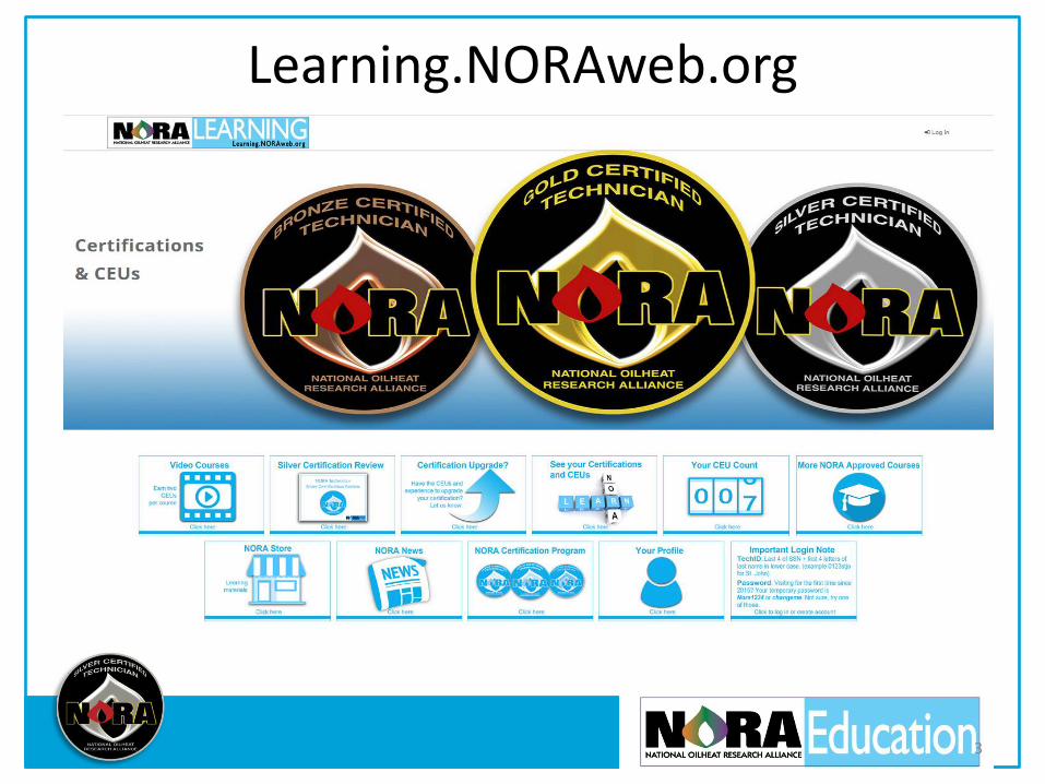
Learning.NORAweb.org
3
Chapter 1: Oil Burners
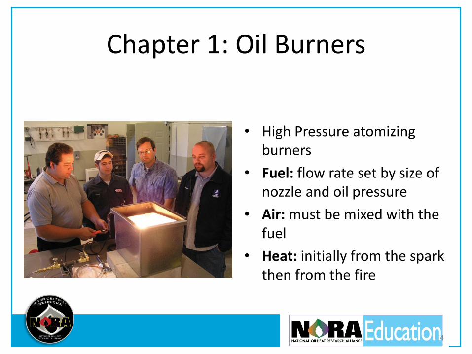
• High Pressure atomizing burners
• Fuel: flow rate set by size of nozzle and oil pressure
• Air: must be mixed with the fuel
• Heat: initially from the spark then from the fire
4
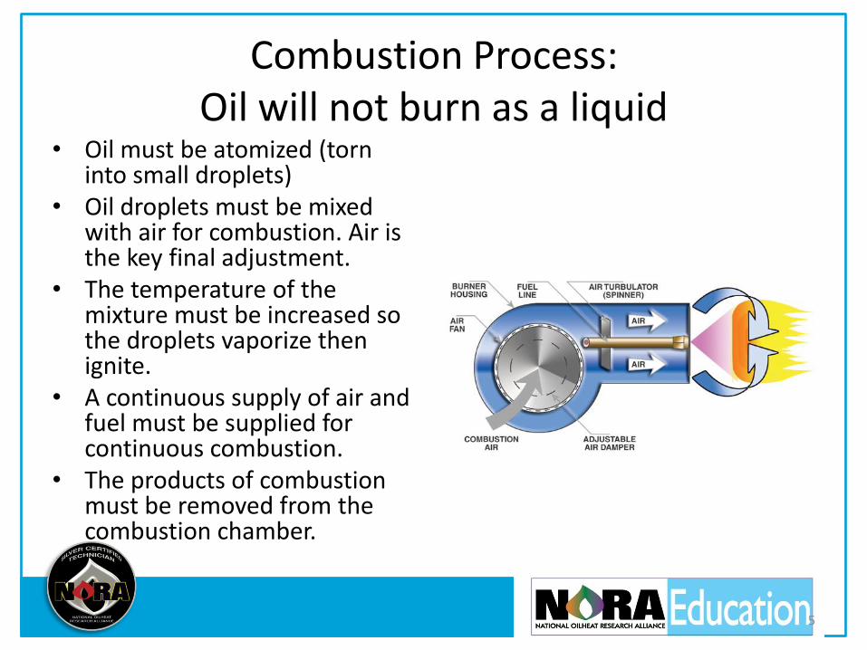
Combustion Process: Oil will not burn as a liquid
• Oil must be atomized (torn into small droplets)
• Oil droplets must be mixed with air for combustion. Air is the key final adjustment.
• The temperature of the mixture must be increased so the droplets vaporize then ignite.
• A continuous supply of air and fuel must be supplied for continuous combustion.
• The products of combustion must be removed from the combustion chamber.
5

Flame Retention Burners
• Better air-oil mixing: Clean Burning and hotter flames with less excess air
• High Static Pressure: more stable flames, able to push through more restrictive heat exchangers
6
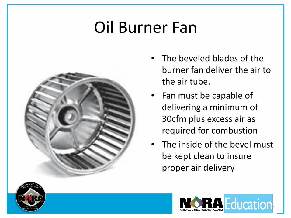
Oil Burner Fan
• The beveled blades of the burner fan deliver the air to the air tube.
• Fan must be capable of delivering a minimum of 30cfm plus excess air as required for combustion
• The inside of the bevel must be kept clean to insure proper air delivery
7
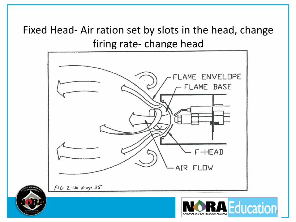
Fixed Head- Air ration set by slots in the head, change firing rate- change head
8

Adjustable Head- Move the head relative to throttle ring to change the air ratio
9

Chapter 2: Heating Oil
• Heating oil is a hydrocarbon fossil fuel manufactured from crude oil in a refinery. It is made up primarily of Hydrogen and Carbon atoms
• #2 oil contains approximately 140,000 BTU’s per gallon
10

Properties of Heating Oil
• Flash Point: the lowest temp. that the fuel will flash but not continue to burn- over 100
• Ignition Point: the lowest temp. when rapid combustion of the fuel takes place in air- over 500
• Pour Point: lowest temp. at which it will flow. Can be lowered by blending with kerosene or additives.
11

12

Sulfuric Acid
• Some of the sulfur in the oil burns, mixes with the water and creates sulfuric acid.
• If the acid condenses in the heat exchanger it creates scale. It also damages the flue liner and eats holes in the flue pipe.
13

NORA Silver 14

Renewable*, Positive Energy Balance, 5.54-1 Biodegradable, Sulfur Free
15
• Bioheat® fuel- minimum of 2% and maximum of 5% ASTM D 6751 biodiesel blended with ASTM D 396 heating oil.
• Requires: No retrofit or equipment modifications, No change in service protocols, Delivery, Installation, Service Infrastructure already exist
The biodiesel portion of Bioheat® is a renewable advanced biofuel as defined by the U.S. EPA Renewable Fuel Standard
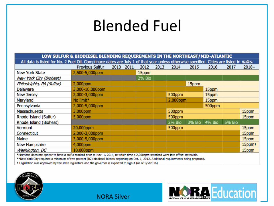
Blended Fuel
NORA Silver 16
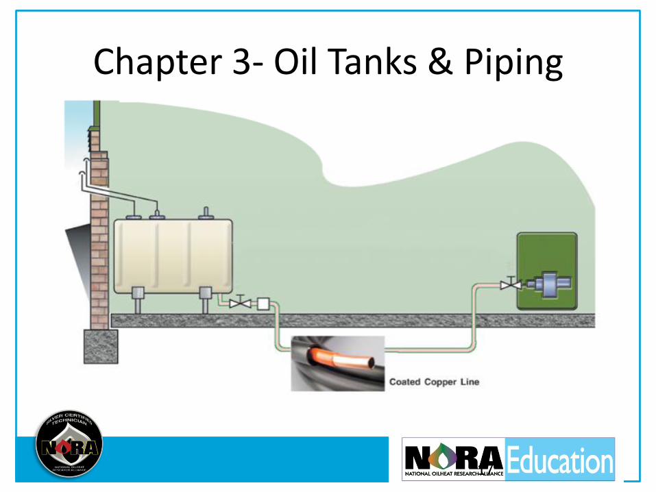
Chapter 3- Oil Tanks & Piping
17
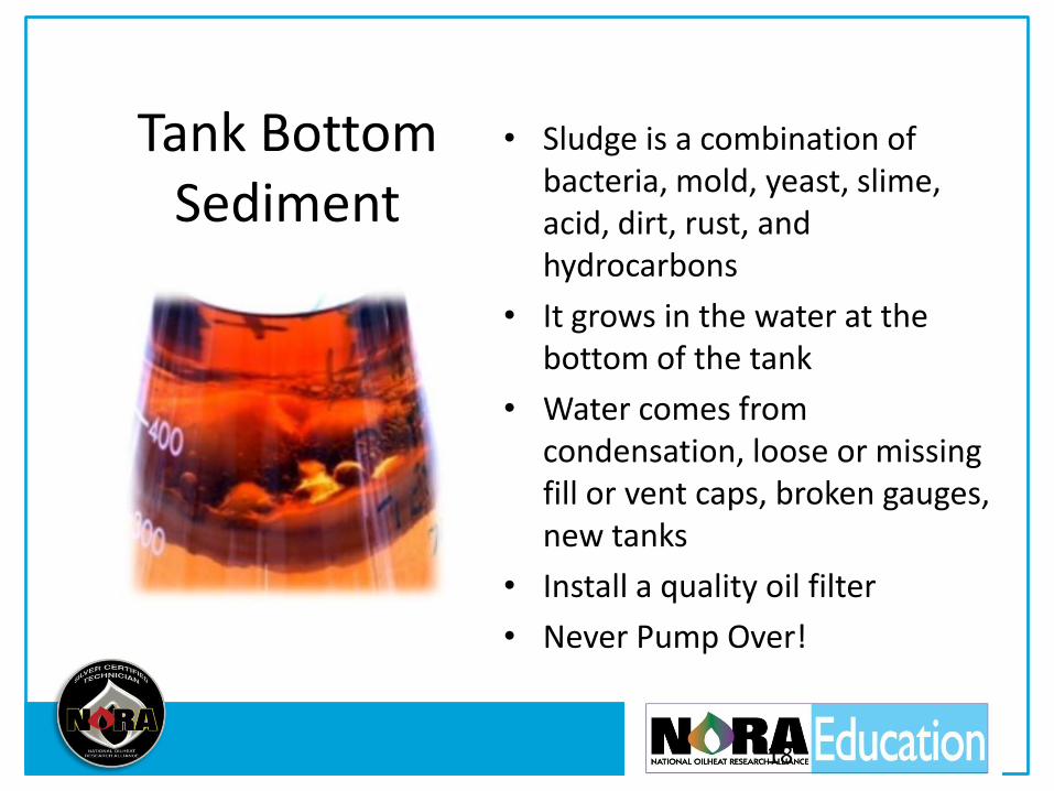
Tank Bottom Sediment
• Sludge is a combination of bacteria, mold, yeast, slime, acid, dirt, rust, and hydrocarbons
• It grows in the water at the bottom of the tank
• Water comes from condensation, loose or missing fill or vent caps, broken gauges, new tanks
• Install a quality oil filter
• Never Pump Over!
18

Proper Tank Installation
• Locate indoors if possible, on solid base, fill & vent piped outdoors
• Pitch fill and vent toward tank, swing joints, steel pipe, malleable fittings, 1 ¼” fill and vent.
• Vent alarm (no whistle- no fill!) gauge, filter, 5 feet from burner
• Draw from bottom of tank, pitch 1/4” for every 1’
• Sleeve and protect oil lines, no compression fittings, fusible valves, no Teflon, no fittings below floor
• Regularly inspect tanks and fix problems
19
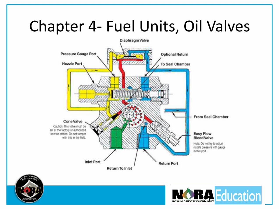
Chapter 4- Fuel Units, Oil Valves
20

Fuel Units
Function:
• lift the oil from the tank
• protect the nozzle
• deliver oil at a constant and regulated pressure to the nozzle
• provides clean cut-off that Stops gravity flow of fuel to nozzle
21
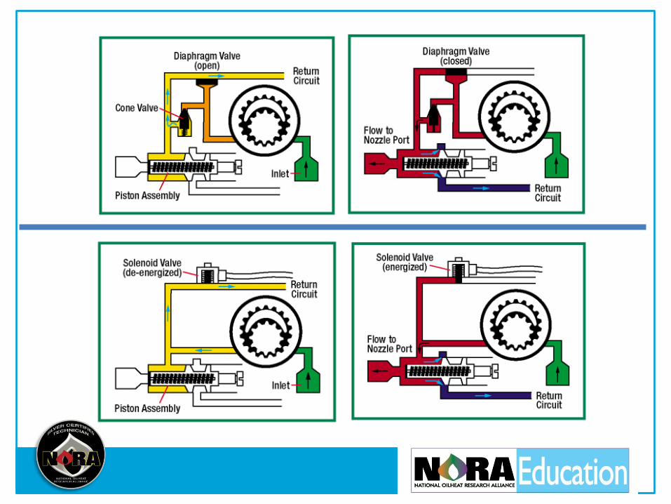

Pressure • Pump pressure is factory set at
100 psi. To adjust pressure and check cut-off install pressure gauge in nozzle port.
• On shut down pressure should drop and hold.
• Pulsating pressure caused by: air leaks, dirty strainer, worn gear set
• Pump noise caused by: high vacuum, air leaks, worn gear set
23
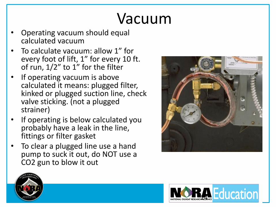
Vacuum • Operating vacuum should equal
calculated vacuum • To calculate vacuum: allow 1” for
every foot of lift, 1” for every 10 ft. of run, 1/2” to 1” for the filter
• If operating vacuum is above calculated it means: plugged filter, kinked or plugged suction line, check valve sticking. (not a plugged strainer)
• If operating is below calculated you probably have a leak in the line, fittings or filter gasket
• To clear a plugged line use a hand pump to suck it out, do NOT use a CO2 gun to blow it out
24
One Pipe Versus Two • 2 pipe is self bleeding
• Problems:
– Pumps deliver over 15 gph, cleaning the tank thru the filter
– Return lines are at 2 psi, leaking return does not effect burner performance
– Copper is a catalyst that destabilizes oil
• Remember: One pipe: by-pass plug out,
Two pipe: by-pass plug in!
25
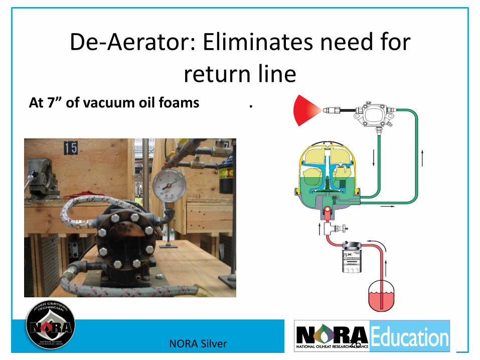
De-Aerator: Eliminates need for
return line At 7” of vacuum oil foams .
NORA Silver 26
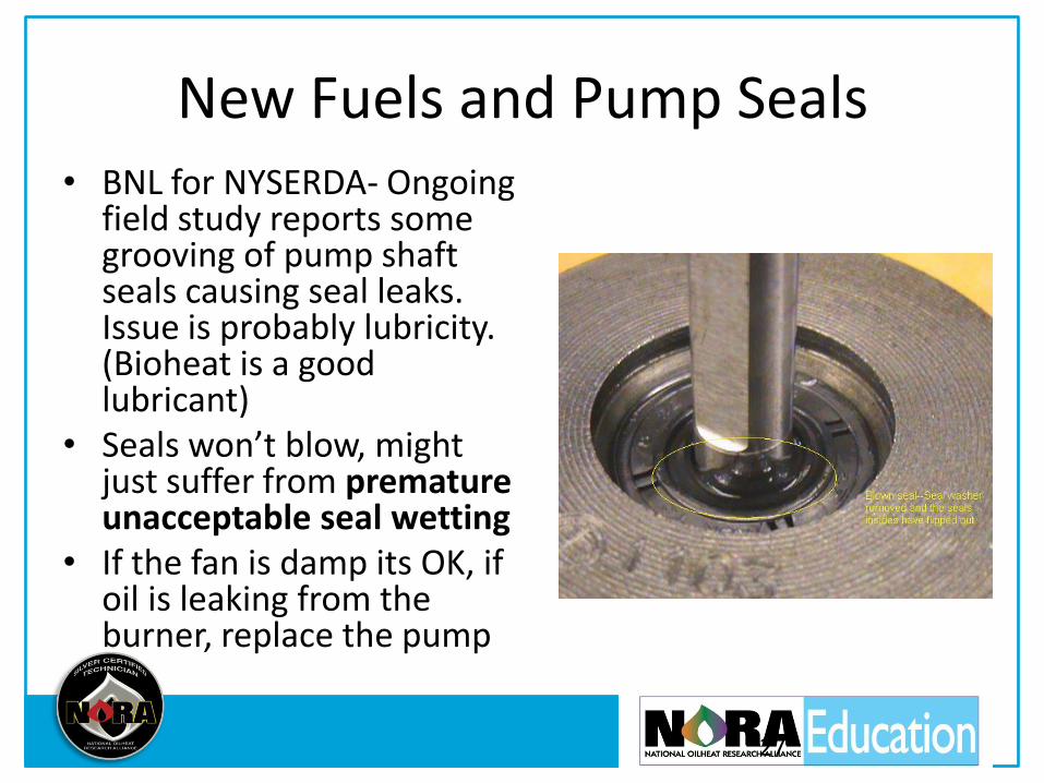
New Fuels and Pump Seals • BNL for NYSERDA- Ongoing
field study reports some grooving of pump shaft seals causing seal leaks. Issue is probably lubricity. (Bioheat is a good lubricant)
• Seals won’t blow, might just suffer from premature unacceptable seal wetting
• If the fan is damp its OK, if oil is leaking from the burner, replace the pump
27
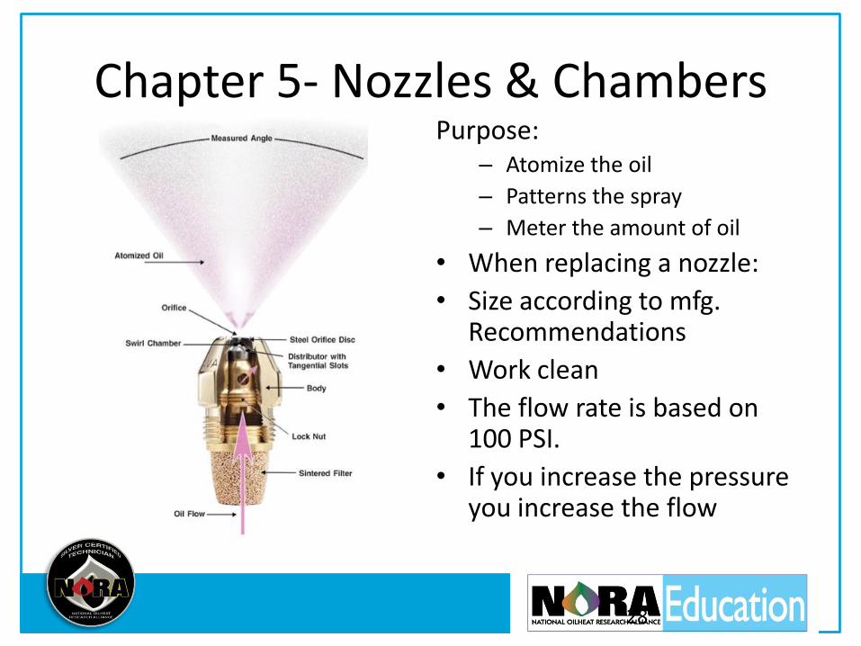
Chapter 5- Nozzles & Chambers Purpose:
– Atomize the oil
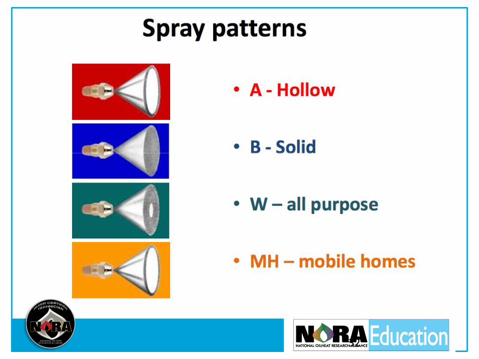
– Patterns the spray
– Meter the amount of oil
• When replacing a nozzle:
• Size according to mfg. Recommendations
• Work clean
• The flow rate is based on 100 PSI.
• If you increase the pressure you increase the flow
28

29
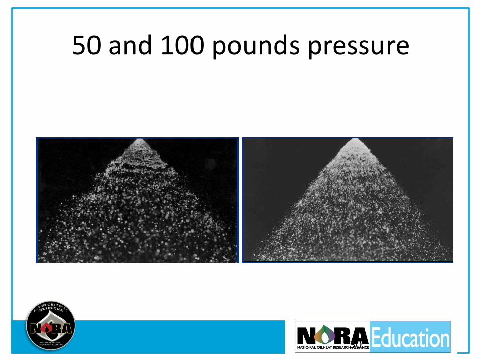
50 and 100 pounds pressure
30
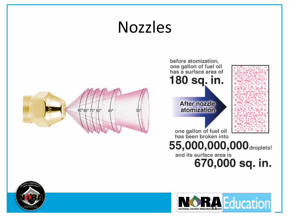
Nozzles
31
32

Cold Oil Increases Viscosity
To minimize effects:
Increase the pump pressure
Install a nozzle line pre-heater
Use additives or kerosene to reduce viscosity
33

After Drip
Causes: defective pressure regulating valve, air in the nozzle line, oil expansion due to heat
Solutions: pump pressure cut-off test, check for air leaks, de-aerator, anti-drip nozzles, motor delay-off (post purge)
34
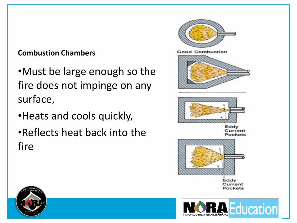
Combustion Chambers
•Must be large enough so the fire does not impinge on any surface,
•Heats and cools quickly,
•Reflects heat back into the fire
35
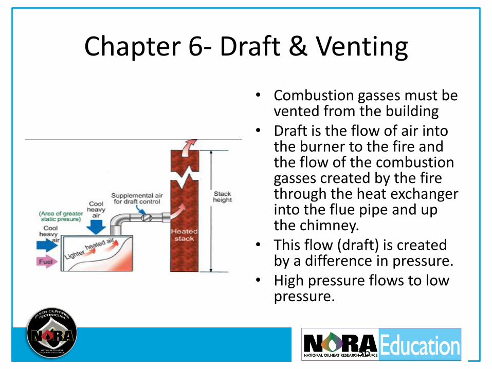
Chapter 6- Draft & Venting
• Combustion gasses must be vented from the building
• Draft is the flow of air into the burner to the fire and the flow of the combustion gasses created by the fire through the heat exchanger into the flue pipe and up the chimney.
• This flow (draft) is created by a difference in pressure.
• High pressure flows to low pressure.
36
Draft Facts • Natural draft in a chimney is created by heat (thermal draft) and
wind (currential draft). Draft is measured in inches of water column, -.02”wc.
• Key measurement is draft over the fire (-.01 to-.02”wc). We also measure draft at the breech. The difference between the two is draft drop. A large draft drop indicates soot and scale buildup
• Draft is effected by the temperature difference between outside air and flue gasses, the barometric pressure, the wind blowing over the chimney, and the humidity levels
• Draft regulators decrease overfire draft to steady low draft
37

Water Heater and Furnace
38

Chimney Troubles
•New appliances have dramatically increased efficiency and reduced stack temperatures
•On cold starts and low temperatures the water vapor in the combustion gasses condense
•Net stack temperature should be above about 350 degrees Fo
39
Chimney Lining
40

Alternative Venting
Draft Inducers: helps the chimney
Power Venters: pull the combustion gasses through the heat exchanger and out of the building
Direct Vent: uses the static pressure of the burner to push the gasses
41
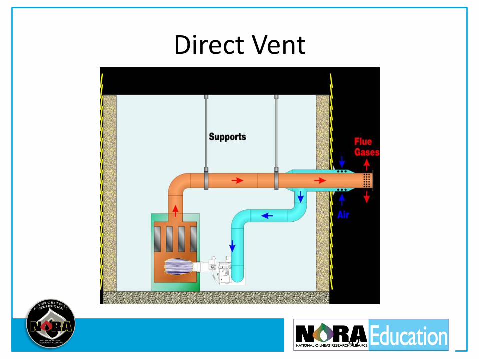
Direct Vent
42
Chapter 7- Combustion
43

44
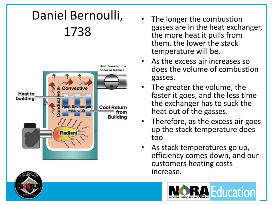
Daniel Bernoulli, 1738
• The longer the combustion gasses are in the heat exchanger, the more heat it pulls from them, the lower the stack temperature will be.
• As the excess air increases so does the volume of combustion gasses.
• The greater the volume, the faster it goes, and the less time the exchanger has to suck the heat out of the gasses.
• Therefore, as the excess air goes up the stack temperature does too
• As stack temperatures go up, efficiency comes down, and our customers heating costs increase.
45
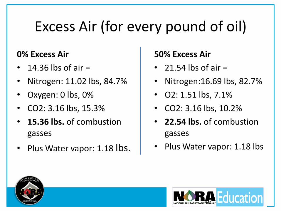
Excess Air (for every pound of oil)
0% Excess Air
• 14.36 lbs of air =
• Nitrogen: 11.02 lbs, 84.7%
• Oxygen: 0 lbs, 0%
• CO2: 3.16 lbs, 15.3%
• 15.36 lbs. of combustion gasses
• Plus Water vapor: 1.18 lbs.
50% Excess Air
• 21.54 lbs of air =
• Nitrogen:16.69 lbs, 82.7%
• O2: 1.51 lbs, 7.1%
• CO2: 3.16 lbs, 10.2%
• 22.54 lbs. of combustion gasses
• Plus Water vapor: 1.18 lbs
46

Wet Kit versus Digital
47
Lack of air in the combustion air zone
• Insulation, tight windows and doors, and tight construction can prevent outside air from entering the building.
• Oilburner combustion requires a great deal of air to operate properly.
• It competes with the fireplace, the exhaust fans, and the clothes dryer for air.
• All of these fans drawing on the air in a tight house makes it difficult for the oil burner to draw in enough combustion air.
• With the building so tight, the indoor air pressure drops below the outdoor air pressure.
• The burner becomes back-vented, resulting in odors, soot and smoke, and Carbon monoxide.
• To insure CO does not enter the building adjust burners properly and be sure the venting system is working
• ‘Isolated combustion’ (ducting outside air directly to the burner) is the best solution. There are many effective isolated combustion air options available.
48

49
Combustion Testing
• Combustion tests: measure temperature of the flue gasses, draft over the fire, smoke in the flue gasses, and amount of excess air
• Steady state efficiency is the net stack temperature and the amount of excess air (CO2 or O2)
• The 1/4” holes for testing must be between the breech and the draft regulator, not in an elbow
• Before using a draft gauge zero out the scale to adjust for barometric pressure
50
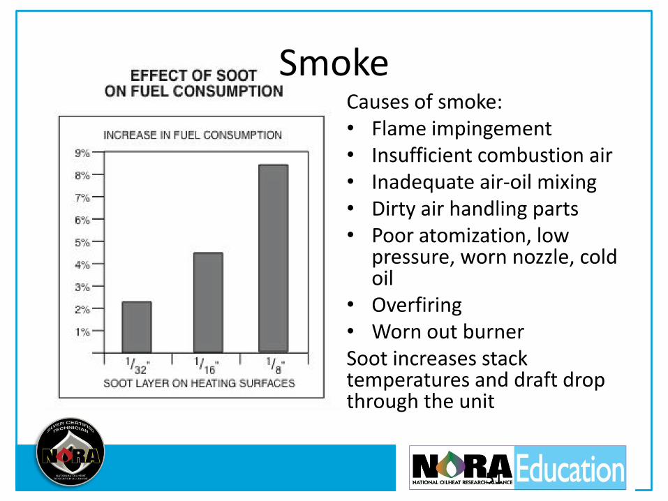
Causes of smoke: • Flame impingement • Insufficient combustion air • Inadequate air-oil mixing • Dirty air handling parts • Poor atomization, low
pressure, worn nozzle, cold oil
• Overfiring • Worn out burner Soot increases stack temperatures and draft drop through the unit
51
Smoke

Smoke Tester
• Smoke becomes soot that insulates the heat exchanger surfaces and lowers efficiency
• 10 full strokes are needed to draw the proper amount of flue gas through the paper
• Adjust to zero, trace first then add a bit more air
52
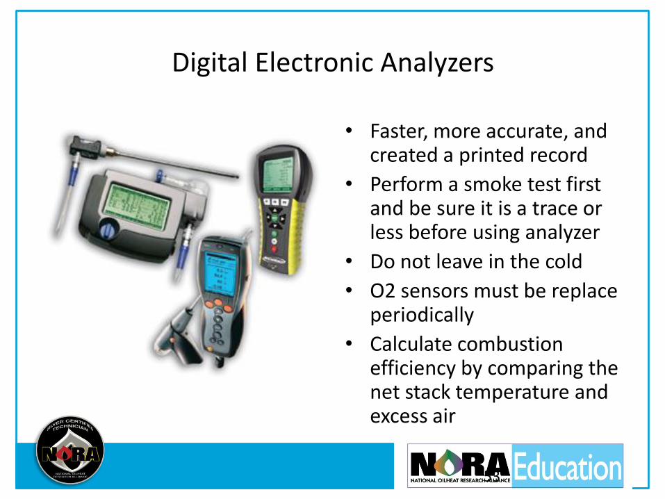
Digital Electronic Analyzers
• Faster, more accurate, and created a printed record
• Perform a smoke test first and be sure it is a trace or less before using analyzer
• Do not leave in the cold
• O2 sensors must be replace periodically
• Calculate combustion efficiency by comparing the net stack temperature and excess air
53
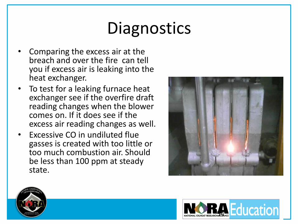
Diagnostics • Comparing the excess air at the
breach and over the fire can tell you if excess air is leaking into the heat exchanger.
• To test for a leaking furnace heat exchanger see if the overfire draft reading changes when the blower comes on. If it does see if the excess air reading changes as well.
• Excessive CO in undiluted flue gasses is created with too little or too much combustion air. Should be less than 100 ppm at steady state.
54
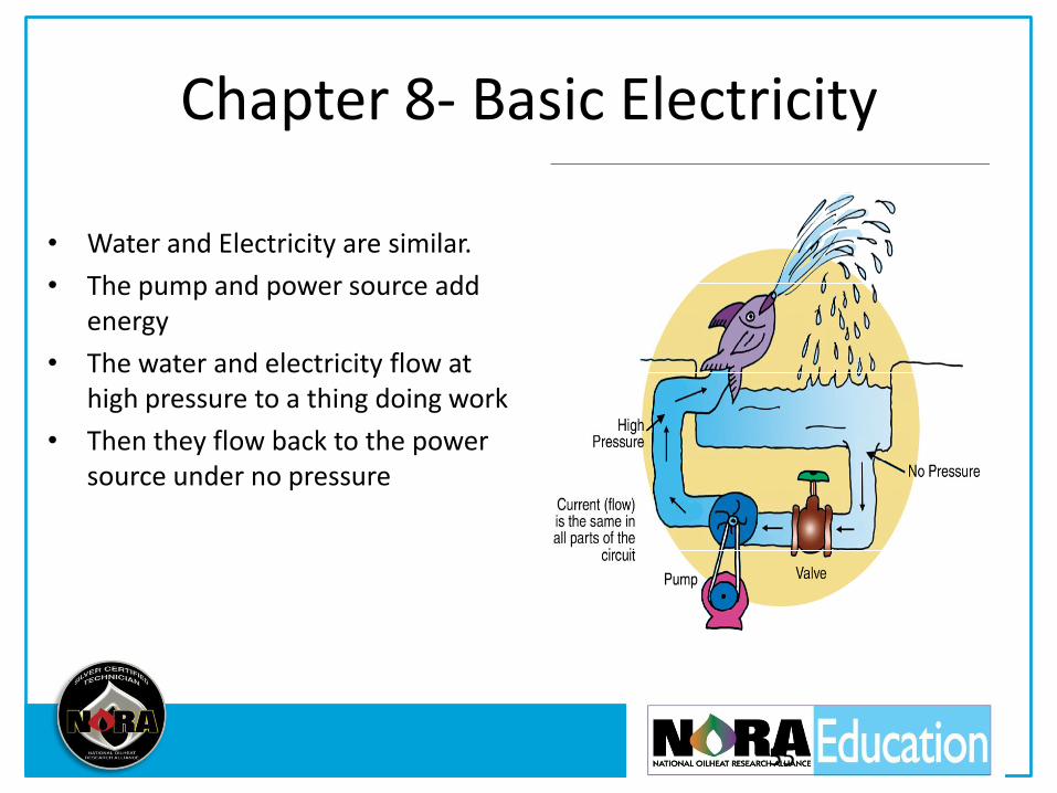
Chapter 8- Basic Electricity
• Water and Electricity are similar.
• The pump and power source add energy
• The water and electricity flow at high pressure to a thing doing work
• Then they flow back to the power source under no pressure
55
Electrical Terms
• Volts- Electric potential, like water pressure
• Amps- the amount of electric current flowing in the wire.
• Ohms- the resistance to flow, heat is created by resistance
• Ohm’s Law- Volts = Amps times Ohms
• Watts- Amount of work being done, Watts = Volts times Amps
56
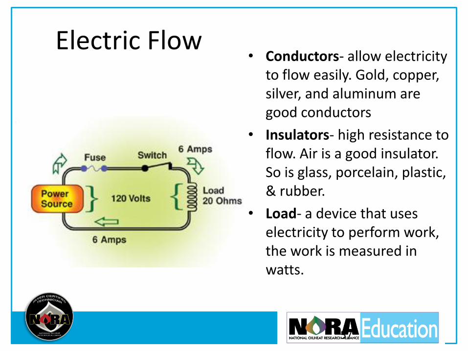
Electric Flow • Conductors- allow electricity
to flow easily. Gold, copper, silver, and aluminum are good conductors
• Insulators- high resistance to flow. Air is a good insulator. So is glass, porcelain, plastic, & rubber.
• Load- a device that uses electricity to perform work, the work is measured in watts.
57
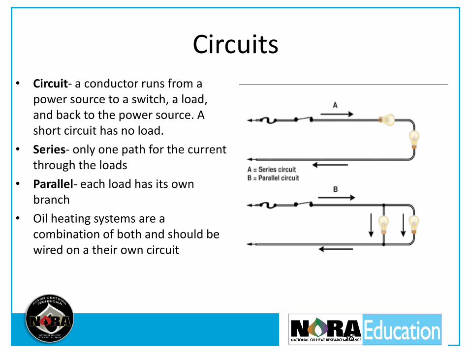
Circuits • Circuit- a conductor runs from a
power source to a switch, a load, and back to the power source. A short circuit has no load.
• Series- only one path for the current through the loads
• Parallel- each load has its own branch
• Oil heating systems are a combination of both and should be wired on a their own circuit
58
Alternating and Direct Current- AC/DC
• Direct current comes from a battery. Only flows in one direction
• Alternating current changes direction, flowing back and forth in the wire. Each back and forth change is a cycle. In North America, the electricity cycles 60 times a second, 120 changes of direction.
• The current delivers power to the load no matter which way it is flowing. The power goes from zero to the required number of watts and back to zero 120 times a second.
59
60
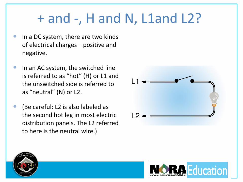
+ and -, H and N, L1and L2? In a DC system, there are two kinds
of electrical charges—positive and negative.
In an AC system, the switched line is referred to as “hot” (H) or L1 and the unswitched side is referred to as “neutral” (N) or L2.
(Be careful: L2 is also labeled as the second hot leg in most electric distribution panels. The L2 referred to here is the neutral wire.)
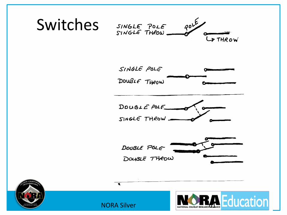
Switches
NORA Silver 61

Bimetal Switch
62

Electromagnet, Solenoids
63
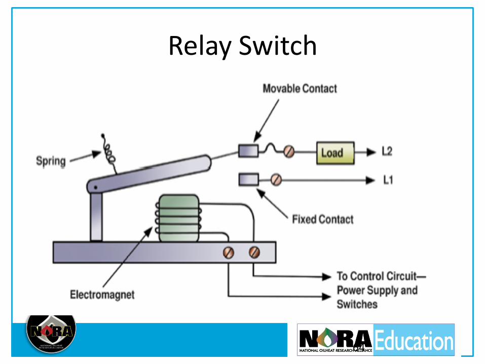
Relay Switch
64
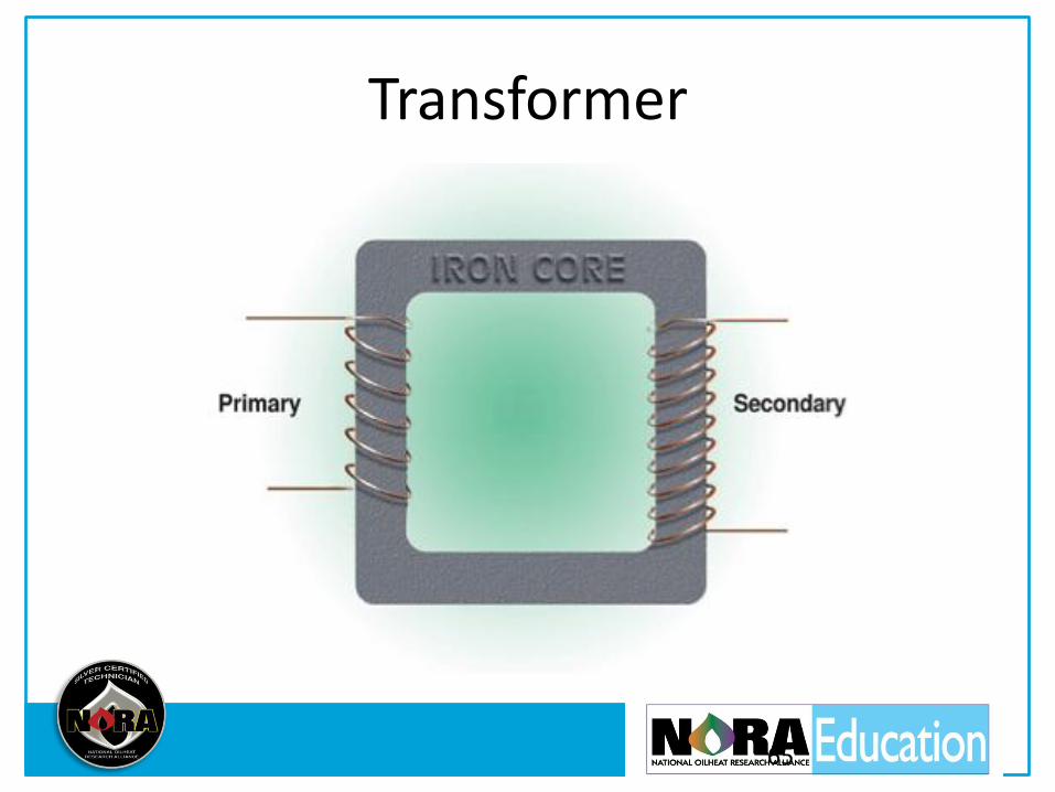
Transformer
65

Motor
66

Voltmeter
• Measures the difference in electric pressure between two points in the circuit
• Volts applied are volts used
• Parallel to the load being measured
• Allows very little electricity to flow through them
67
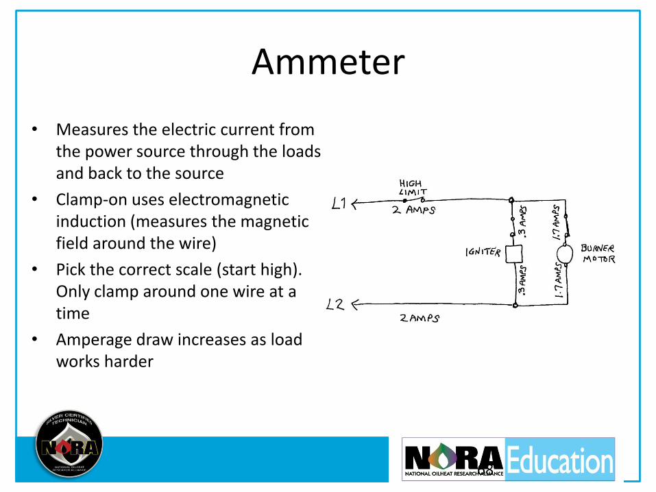
Ammeter
• Measures the electric current from the power source through the loads and back to the source
• Clamp-on uses electromagnetic induction (measures the magnetic field around the wire)
• Pick the correct scale (start high). Only clamp around one wire at a time
• Amperage draw increases as load works harder
68
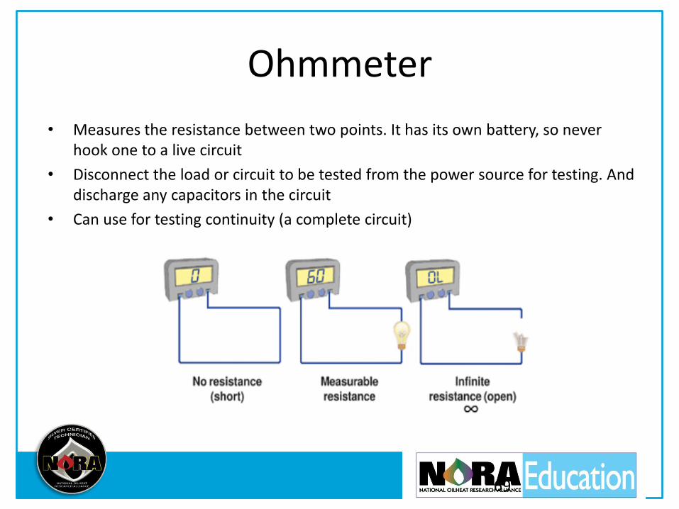
Ohmmeter
• Measures the resistance between two points. It has its own battery, so never hook one to a live circuit
• Disconnect the load or circuit to be tested from the power source for testing. And discharge any capacitors in the circuit
• Can use for testing continuity (a complete circuit)
69

Chapter 9- Ignition Systems
• The ignition transformer is a step-up transformer: primary voltage is 120 volts, secondary is 10,000 to 14,000 volts
• Intermittent ignition- ignition is on the whole time the burner runs
• Interrupted ignition- ignition shuts off after flame is established, uses less electricity & longer component life
• The advantages of solid state igniters are: less effected by voltage drops, higher peak output voltage, use less electricity
• Test igniters by setting the gap between the springs to 1/2” and energize, spark will jump the gap if OK
NORA Silver 70
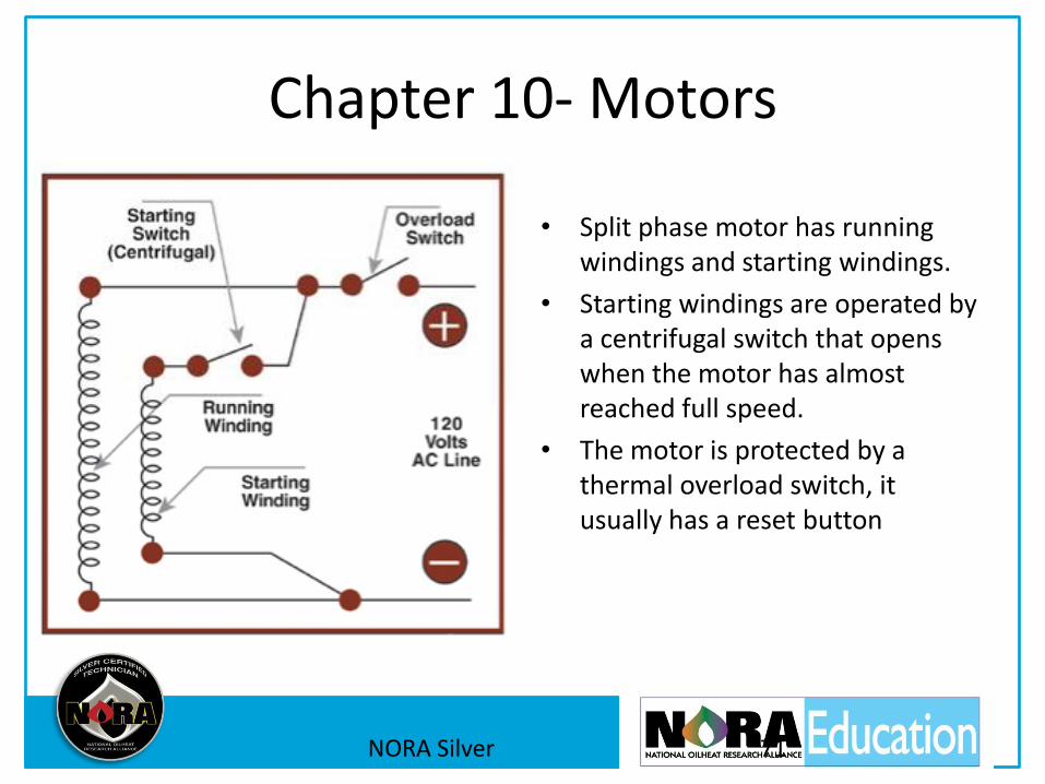
Chapter 10- Motors
• Split phase motor has running windings and starting windings.
• Starting windings are operated by a centrifugal switch that opens when the motor has almost reached full speed.
• The motor is protected by a thermal overload switch, it usually has a reset button
NORA Silver 71

Capacitor Start Motors
• Circulator motors and larger burner motors
• Capacitors build an electric charge an store it until needed
• Creates much greater phase shift that gives it more starting torque
• Remember to discharge the capacitor before testing with an Ohmmeter
NORA Silver 72
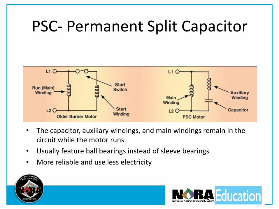
PSC- Permanent Split Capacitor
73
• The capacitor, auxiliary windings, and main windings remain in the circuit while the motor runs
• Usually feature ball bearings instead of sleeve bearings
• More reliable and use less electricity
74

ECM
• Electrically Commutated Magnetic Motor
• Used for blower motors on warm air systems and circulators on hot water
• Variable motor speed, low power consumption, means superior efficiency and reduced noise
75
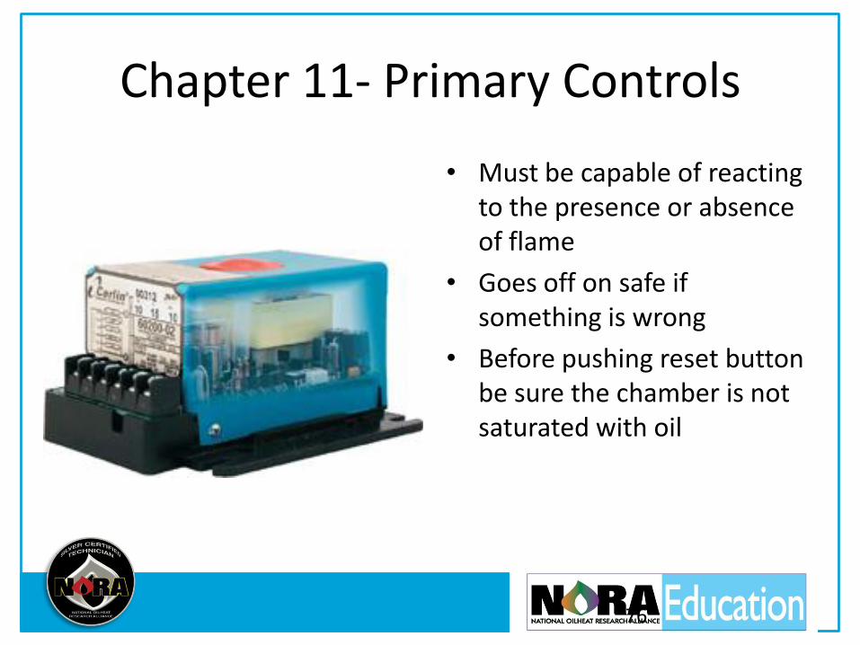
Chapter 11- Primary Controls
• Must be capable of reacting to the presence or absence of flame
• Goes off on safe if something is wrong
• Before pushing reset button be sure the chamber is not saturated with oil
76
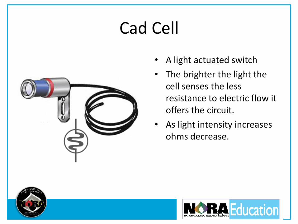
Cad Cell
• A light actuated switch
• The brighter the light the cell senses the less resistance to electric flow it offers the circuit.
• As light intensity increases ohms decrease.
77
78
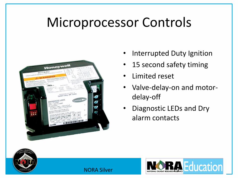
Microprocessor Controls
• Interrupted Duty Ignition
• 15 second safety timing
• Limited reset
• Valve-delay-on and motor-delay-off
• Diagnostic LEDs and Dry alarm contacts
NORA Silver 79
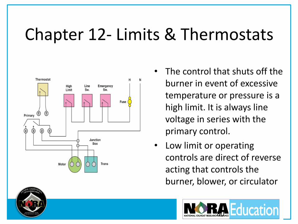
Chapter 12- Limits & Thermostats
• The control that shuts off the burner in event of excessive temperature or pressure is a high limit. It is always line voltage in series with the primary control.
• Low limit or operating controls are direct of reverse acting that controls the burner, blower, or circulator
80
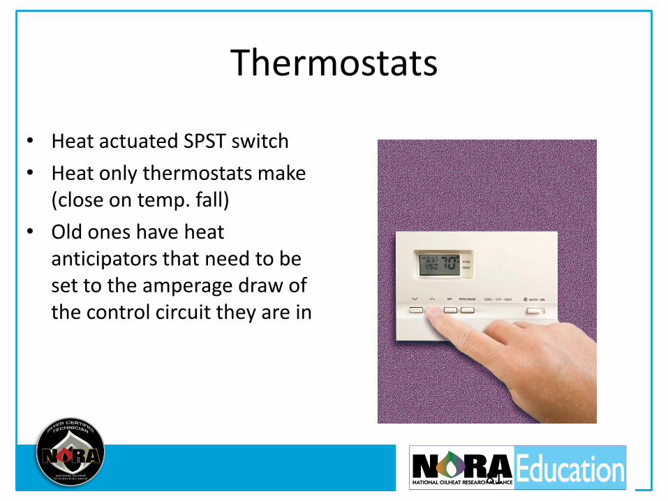
Thermostats
• Heat actuated SPST switch
• Heat only thermostats make (close on temp. fall)
• Old ones have heat anticipators that need to be set to the amperage draw of the control circuit they are in
81
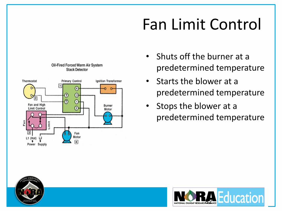
Fan Limit Control
• Shuts off the burner at a predetermined temperature
• Starts the blower at a predetermined temperature
• Stops the blower at a predetermined temperature
82

Hot Water Heating System
83
• Switching relay- controls the circulator (line voltage) with low voltage thermostat
• Reverse acting aquastat- stops the circulator when the boiler water falls below the set point
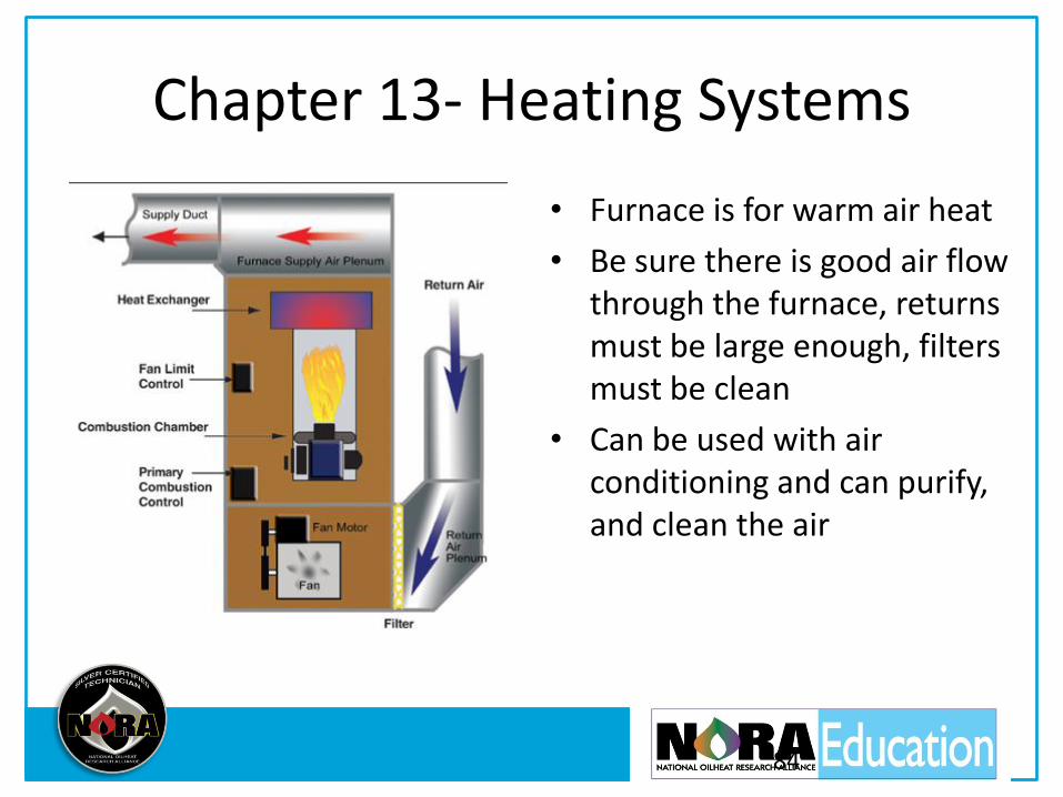
Chapter 13- Heating Systems
• Furnace is for warm air heat
• Be sure there is good air flow through the furnace, returns must be large enough, filters must be clean
• Can be used with air conditioning and can purify, and clean the air
84
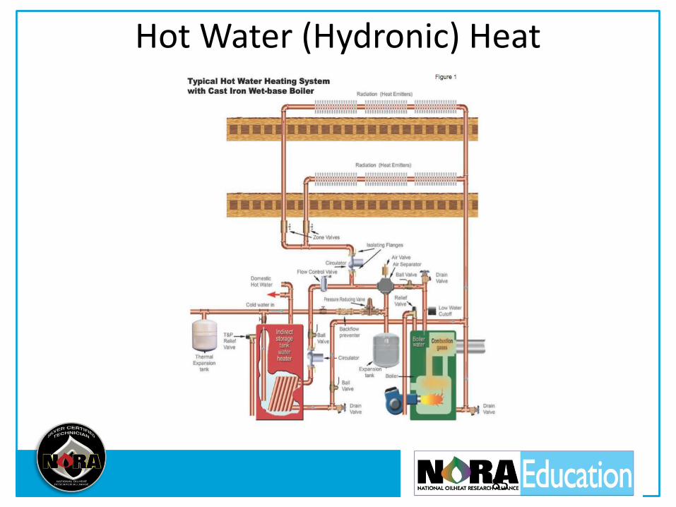
Hot Water (Hydronic) Heat
85

Hydronic Requirements
• Proper air elimination
• Proper pipe sizing
• System water expansion
• 12 PSI pushes water 28’ up a pipe
NORA Silver 86

Steam, 2 PSI
NORA Silver 87
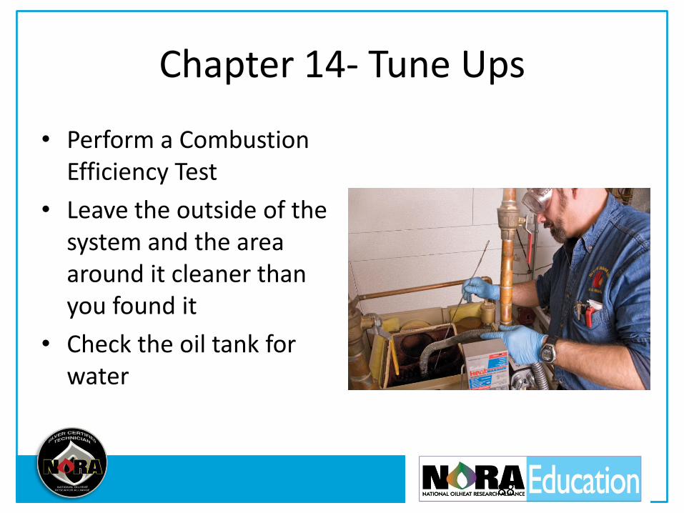
Chapter 14- Tune Ups
• Perform a Combustion Efficiency Test
• Leave the outside of the system and the area around it cleaner than you found it
• Check the oil tank for water
88
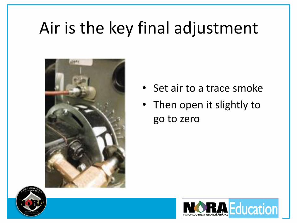
Air is the key final adjustment
• Set air to a trace smoke
• Then open it slightly to go to zero
89

Ch. 15 Service Procedures • You must figure out what
happened, why it happened, how to fix it, and how to keep it from happening again.
• Look beyond the symptoms to find the cause of the problem. Pushing the reset button does not fix the problem, it just makes the burner try to start again.
90
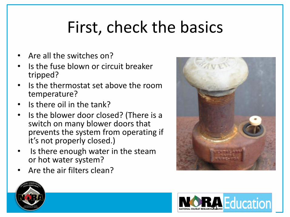
First, check the basics
• Are all the switches on? • Is the fuse blown or circuit breaker
tripped? • Is the thermostat set above the room
temperature? • Is there oil in the tank? • Is the blower door closed? (There is a
switch on many blower doors that prevents the system from operating if it’s not properly closed.)
• Is there enough water in the steam or hot water system?
• Are the air filters clean?
91
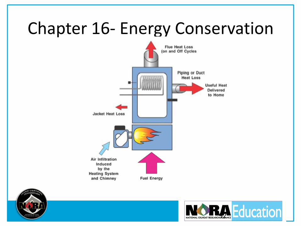
Chapter 16- Energy Conservation
92

On-Cycle Loss
• Adjust burner properly (Excess air increases stack temperatures and decreases efficiency)
• Keep heat exchanger surfaces clean
• Replace inefficient burners and boilers or furnaces
93

Off-Cycle Loss
• Much greater for old units with wide open flue passages
• Increased by air leaks into the heat exchanger
• Greater for units whose air bands are open wider
• Greater for units that are oversized
94
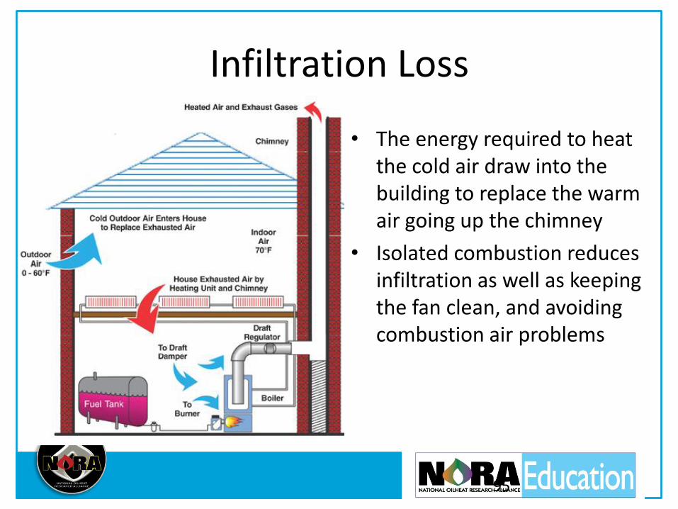
Infiltration Loss
• The energy required to heat the cold air draw into the building to replace the warm air going up the chimney
• Isolated combustion reduces infiltration as well as keeping the fan clean, and avoiding combustion air problems
95
REPLACING THE BOILER OR FURNACE REDUCES ON-CYCLE, OFF-CYCLE, AND INFILTRATION
LOSSES.
It is the best investment your customer can make!
96
Test Taking Tips
• Take your time
• Read all the answers before marking the sheet
• If not sure skip it and come back, just be sure to skip a space on the answer sheet!
• If unsure pick the one that seems most right. There is no penalty for guessing
• NORA must have your email address on the back of the answer sheet
• @ means “at” as in [email protected]
97