nonlinear finite element analysis of steel-concrete...
TRANSCRIPT

NONLINEAR FINITE ELEMENT ANALYSIS OF STEEL-CONCRETE
COMPOSITE SLABS USING EXPLICIT DYNAMICS PROCEDURE
MOHAMMAD JOSHANI
A project report submitted in partial fulfillment of the
requirements for the award of the degree of
Master of Engineering (Civil-Structure)
Faculty of Civil Engineering
Universiti Teknologi Malaysia
APRIL 2010

v
ABSTRACT
Composite slab construction using permanent cold-formed steel decking has
become one of the most economical and industrialized forms of flooring systems in
modern building structures. Structural performance of the composite slab is affected
directly by the horizontal shear bond phenomenon at steel-concrete interface layer.
This study utilizes 3D nonlinear finite element quasi-static analysis technique
through explicit dynamics procedure to analyze the shear bond damage and fracture
mechanics of the composite slabs. Cracking of the plain concrete over the
corrugated steel deck has been modeled considering the mixed modes fracture
mechanisms by means of concrete damaged plasticity model available in ABAQUS
software version 6.9. The interface layer damage was simulated with cohesive
elements presented in ABAQUS software considering three modes of fracture.
Cohesive fractures properties such as fracture energy and initiation stress have been
derived from horizontal shear stress versus end slip curves which were extracted
from bending test of a series of small scale specimens. The proposed model is
verified through comparison with experimental data which demonstrated that the
results of the numerical analyses match with valid experimental results. Therefore
these calibrated and validated models can predict the structural response of steel-
concrete composite slabs. This will reduce the cost of empirical works which in
accordance with present design specifications are mandatory in order to investigate
the behavior and load bearing capacity of such structural systems.

vi
ABSTRAK
Pembinaan papak rencam dengan menggunakan deck keluli terbentuk sejuk yang
kekal merupakan salah satu jenis sistem papak yang paling ekonomi bagi struktur
bangunan moden. Prestasi struktur bagi papak rencam dipengaruhi secara langsung
oleh fenomena ikatan ricih mengufuk di antara muka keluli dan konkrit. Dalam
kajian ini, analisis ‘quasi-static’ unsur terhingga 3D yang menggunakan prosedur
‘explicit dynamics’ telah dijalankan bagi menilai kerosakan ikatan ricih mengufuk
dan mekanik retakan pada papak rencam. Retakan pada konkrit di atas dek keluli
beralun telah dimodelkan dengan mengambil kira mekanik retakan dengan mod
tergabung. Model kemusnahan plastic yang terdapat dalam perisian ABAQUS telah
diguna dengan mengambil kira tiga mode retakan. Kemusnahan pada antara muka
keluli dan konkrit telah dimodel dengan unsur ‘cohesive’. Sifat retakan ‘cohesive’
seperti tenaga retakan dan tegasan pemula telah diterbitkan daripada geraf tegasan
ricih mengufuk lawan gelangsaran hujung yang diambil daripada ujian lenturan
bersaiz kecil. Model analisis yang dicadangkan dalam kajian ini disahkan
kejituannya dengan mebuat perbandingan antara hasil analisis dengan data ujikaji.
Hasilnya, model analisis ini boleh diguna untuk menilai gerak balas struktur papak
rencam. Hal ini boleh mengurangkan kerja ujikaji yang dahulunya mesti dilakukan
untuk menentukan kelakuan sebenar dan kebolehtanggungan beban system papak
rencam.

vii
TABLE OF CONTENTS
CHAPTER TITLE PAGE
DECLARATION ii
DEDICATION iii
ACKNOWLEDGEMENT iv
ABSTRACT v
ABSTRAK vi
TABLE OF CONTENTS vii
LIST OF TABLES x
LIST OF FIGURES xi
LIST OF APPENDICES xx
NOMENCLATURES xxi
I INTRODUCTION 1
1.1 Introduction to Steel-Concrete Composite Slabs 1
1.2 Problem Statement 8
1.3 Aim of Study 10
1.4 Objectives of Study 10
1.5 Scopes of Study 11
1.6 Organization and Outline of Thesis 12
II LITERATURE REVIEW 13
2.1 Introduction 13
2.2 Fracture Mechanics and NFEA 14

viii
2.2.1 Fracture Modes 16
2.2.2 Composite Slab Behavior with Respect
to Fracture Mechanics
17
2.3 Simulation of Composite Slabs 19
2.4 Explicit Dynamics Procedure 21
2.5 Introduction to Cohesive Fracture Theory 22
2.5.1 Concept of Cohesive Zone Model 24
2.5.2 Inter-layer Damage Modeling using
Cohesive Element
26
2.5.3 Cohesive Elements and Insertion
Algorithms
26
2.5.4 Cohesive Element Formulation
2.5.5 Traction Separation Law, TSL
28
30
2.5.6 Interfacial Material Properties 31
2.5.7 Interface Debonding Initiation and
Propagation
32
2.5.7.1 Constitutive Equations for
Interface Damage
32
2.5.7.2 Mixed-mode Debonding
Criterion
34
2.5.7.3 Damage Evolution Law
Implementation
36
2.6 Damaged Plasticity Model for Concrete 42
2.6.1 Post-failure Stress-Strain Relation 46
2.6.2 Fracture Energy Cracking Criterion 47
2.6.3 Defining Compressive Behavior
48
III METHODOLOGY 50
3.1 Introduction 50
3.2 Development of the FE model 51
ix
3.2.1 Models geometry and characterization 51
3.2.2 Finite Element Mesh Generation 57
3.2.3 Concrete Properties Definition 60
3.2.4 Steel Properties Definition 64
3.2.5 Interface Layer Properties Definition 65
3.2.6 Boundary Conditions 68
IV RESULTS AND DISCUSSION 70
4.1 Introduction 70
4.2 Case A (3VL16-4-7.5 composite Slab) 73
4.3 Case B (3VL16-8-7.5 composite Slab) 91
4.4 Case C (3VL16-10-7.5 composite Slab) 107
4.5 Case D (3VL16-12-5 composite Slab) 117
4.6 Case E (3VL16-14-5 composite Slab) 128
V CONCLUSIONS & RECOMMENDATIONS 141
5.1 Conclusions 141
5.2 Recommendations 144
REFERENCES 145
BIBLIOGRAPHY 150
Appendices A - B
159-
164

x
LIST OF TABLES
TABLE NO TITLE PAGE
3.1 Geometry of the various models 52
3.2 Concrete mechanical and brittle cracking properties
used in the FE model (Abdullah R., 2004)
62
3.3 Steel properties (Abdullah R., 2004) 65
3.4 Interfacial layer properties used in the finite element
model
66
4.1 Coefficients for conversion of applied load to
equivalent uniform load
73

xi
LIST OF FIGURES
FIGURE NO TITLE PAGE
1.1 Configuration of a typical steel-concrete composite
slab with trapezoidal decking.
2
1.2 Illustration of an open rib type of composite slab. 2
1.3 Typical Trapezoidal and Re-entrant deck profiles. 4
1.4 Examples of trapezoidal deck profiles: (Left side) Up
to 60 mm deep; (Right side) Greater than 60 mm
deep
5
1.5 Typical forms of interlock in composite slabs 7
2.1 Visualization of general modes of fracture 17
2.2 Steel-concrete composite slab collapse modes. 18
2.3 Application of cohesive zone elements along bulk
element boundaries
23
2.4 Cohesive stresses are related to the crack opening
width (w).
25
2.5 Variation of cohesive stress with respect to the crack
opening displacement in the process zone.
26
2.6 Stress distribution and cohesive crack growth in
mode-I opening for concrete.
29
2.7 Forms of the TSL: a) cubic, b) constant, c)
Exponential, d) Tri-linear
30
2.8 Debonding damage model 31
2.9 Constitutive strain softening equations 32

xii
2.10 (a) Visualization of the process zone at the crack tip,
and definition of displacement jump δ and cohesive
tractions t. (b) Example of mode I cohesive law:
Rose-Smith-Ferrante universal binding law.
34
2.11 Power law form of the shear retention model. 36
2.12 Mode mix measures based on traction 38
2.13 Linear damage evolution. 39
2.14 Illustration of mixed-mode response in cohesive
elements.
40
2.15 Fracture energy as a function of mode mix. 41
2.16 Tensile stress-elongation curves for quasi-brittle
material.
43
2.17 FPZ in Quasi-brittle (concrete). 43
2.18 Response of concrete to uniaxial load in tension (a)
and compression (b).
44
2.19 Illustration of the definition of the cracking strain
used for the definition of tension stiffening data.
46
2.20 Post-failure stress-displacement curve. 47
2.21 Fracture energy illustration. 48
2.22 Definition of the compressive inelastic (or crushing)
strain used for the definition of compression
hardening data.
49
3.1 Geometry of beam corresponding to 3VL16-4-7.5
composite slab.
53
3.2 a) Isometric view of test setup b) Details at supports 54
3.3 Small Scale specimens before concrete casting 55
3.4 Pour stop at the end section of small scale beams 55
3.5 Configuration of the small scale test setup 56
3.6 Picture of a full-scale composite slab specimen 56
3.7 Schematic view of composite slab with trapezoidal
decking (VULCRAFT)
57
3.8 Mesh pattern for 3VL16-4-7.5 composite deck slab 57
3.9 Mesh pattern for 3VL16-8-7.5 composite deck slab 58

xiii
3.10 Mesh pattern for 3VL16-10-7.5 composite deck slab 58
3.11 Mesh pattern for 3VL16-12-5 composite deck slab 59
3.12 Mesh pattern for 3VL16-14-5 composite deck slab 59
3.13 Typical stress-strain relationship for concrete 61
3.14 Concrete behavior: (a) Tensile; (b) Compressive. 63
3.15 Convergence problem in long span composite slabs. 64
3.16 Typical stress-strain relationship for steel (bi-linear
strain hardening)
65
3.17 Horizontal shear bond versus end slip curves for
various models
67
3.18 Boundary conditions for 3VL16-4-7.5 composite
deck slab
69
3.19 Demonstration of interaction surfaces between rigid
body, concrete and neoprene.
69
4.1 Converting the point load in the model to uniform
load (Udin, 2006)
71
4.2 Support reaction force or loading force versus time 74
4.3 Mid-span deflection versus time 74
4.4 Support reaction force versus mid-span deflection 75
4.5 Comparison between experimental force-
displacement curve and predicted structural response
with various smooth factors.
75
4.6 Equivalent uniform load vs. mid-span deflection
curve resulted from ABAQUS
76
4.7 Kinetic energy vs. time curves for concrete, interface
layer and the whole model.
77
4.8 Internal energy vs. time curves for concrete, interface
layer and the whole model
78
4.9 Comparison of kinetic energy and total energy for the
whole model
78
4.10 Damage dissipation energy vs. time curves for
constituent components and for the whole model.
79
4.11 Determination of critical instances in damage 80

xiv
evolution process of 3VL16-4-7.5 composite slab
4.12 Damage status in the concrete and in the cohesive
interface layer when the mid-span displacement is
equal to 2.3mm.
82
4.13 Exhibition of crack development paths in the right
side of the small scale beam tested at Virginia Tech
(Abdullah, 2004).
82
4.14 Damage status in the concrete and in the cohesive
interface layer when the mid-span displacement is
equal to 4.9 mm.
83
4.15 Damage status in the concrete and in the cohesive
interface layer when the mid-span displacement is
equal to 10 mm.
85
4.16 Exhibition of major crack due to slip failure in the
left side of the small scale beam tested at Virginia
Tech (Abdullah, 2004)
85
4.17 Illustration of Major crack due to slip failure at the
right side of the small scale specimen tested at
Virginia Tech (Abdullah, 2004)
86
4.18 Depiction of longitudinal end slip resulted from
analysis with ABAQUS
86
4.19 Von Mises stress contour in whole of the specimen
when time is equal to 0.03 second
87
4.20 (Second picture) Contour of longitudinal shear bond
stress along the length of the composite slab when the
damage status in the interface layer is exhibited with
the first upper picture.
88
4.21 Longitudinal Shear stress vs. time for six random
elements as shown in previous figure.
89
4.22 Variation of end slip according to time for 3VL16-4-
7.5 composite slab.
89
4.23 Longitudinal Shear bond stress vs. end slip 90
4.24 Contour of displacement in direction 2 for 3VL16-4- 90

xv
7.5 composite slab with scale factor allocated equal
by 3.
4.25 Picture of end slip for 3VL16-4-7.5 composite slab
(Abdullah, 2004)
91
4.26 Support reaction force or applied loading force versus
time curve.
92
4.27 Mid-span deflection versus time indicating loading
rate.
93
4.28 Support reaction force or applied loading force versus
mid-span deflection.
93
4.29 Comparison between experimental force-
displacement curve and predicted structural response
94
4.30 Kinetic energy vs. time curves for concrete, interface
layer and the whole model.
94
4.31 Internal energy vs. time curves for concrete, interface
layer and the whole model.
95
4.32 Comparison of kinetic energy and total energy for the whole model.
96
4.33 Damage dissipation energy vs. time curves for
constituent components and for the whole model.
96
4.34 Steps of Damage in Concrete and Interface according
to equivalent uniform load graph.
98
4.35 Damage status in the concrete and in the cohesive
interface when the mid-span displacement is equal to
8.5 mm.
99
4.36 Crack maps for specimen 3VL16-8-7.5 (Abdullah,
2004)
100
4.37 Exhibition of crack development paths in the left side
of the small scale beam tested at Virginia Tech
(Abdullah, 2004)
101
4.38 Damage status in the concrete and in the cohesive
interface when the mid-span displacement is equal to
24 mm.
102
4.39 Picture of longitudinal displacement of the model 103

xvi
which shows that the red color region near the bottom
flange has slipped and displaced to left
4.40 Von Mises stress contour in whole of the specimen at
a certain time.
104
4.41 (Second picture) Contour of longitudinal shear bond
stress along the length of the composite slab.
105
4.42 Longitudinal Shear stress vs. time for some random
elements as shown in previous figure.
105
4.43 Horizontal shear stress versus end slip 106
4.44 Picture of end slip of 3VL16-8-7.5 composite slab 106
4.45 Contour of displacement in direction 2 for steel
decking of 3VL16-8-7.5 composite slab with scale
factor
107
4.46 Buckling shape of steel decking at final stages of
loading tested at Virginia Tech (Abdullah, 2004).
107
4.47 Support reaction force versus time graph. 108
4.48 Mid-span deflection versus time indicating loading
rate.
109
4.49 Support reaction force versus mid-span deflection
graph.
109
4.50 Comparison between experimental force-
displacement curve and predicted structural response
110
4.51 Kinetic energy vs. time curves for concrete, interface
layer and the whole model.
110
4.52 Internal energy vs. time curves for concrete, interface
layer and the whole model.
111
4.53 Comparison of kinetic energy and total energy for the
whole model.
112
4.54 Damage dissipation energy vs. time curves for
concrete, interface layer and the whole model.
112
4.55 Steps of Damage in Concrete and Interface according
to applied uniform load vs. mid-span deflection
graph.
113

xvii
4.56 Damage status in the concrete and in the cohesive
interface when the mid-span displacement is equal to
12 mm.
114
4.57 Picture of longitudinal displacement of the model. 115
4.58 Von Mises stress contour in whole of the specimen at
a certain time step.
115
4.59 Longitudinal Shear stress vs. time for some random
elements at interface layer.
116
4.60 Longitudinal Shear bond stress vs. end slip curve. 116
4.61 Configuration of test set-up for 3VL16-12-5
Composite Slab
117
4.62 Mid-span deflection versus time indicating loading
rate.
117
4.63 Support reaction force versus mid-span deflection
graph.
118
4.64 Equivalent uniform load vs. mid-span deflection
curve resulted from ABAQUS in comparison with
experimental tests.
118
4.65 Kinetic energy vs. time curves for concrete, interface
layer and the whole model.
119
4.66 Internal energy vs. time curves for concrete, interface
layer and the whole model.
120
4.67 Comparison of kinetic energy and total energy for the
whole model.
121
4.68 Damage dissipation energy vs. time curves for
concrete, interface layer and the whole model.
121
4.69 Steps of Damage in Concrete and Interface according
to equivalent uniform load graph.
122
4.70 Damage status in the concrete and in the cohesive
interface when the mid-span displacement is equal to
33 mm.
123
4.71 Picture of crack development paths in the concrete
body
124

xviii
4.72 The cracking pattern matches with numerical analysis
results done by ABAQUS software
124
4.73 Picture of longitudinal displacement of the model 125
4.74 Von Mises stress contour in whole of the specimen at
a certain time step.
126
4.75 Depiction of some random selected elements for
extraction of horizontal shear bond stress vs. time
graphs
126
4.76 Longitudinal Shear stress vs. time for some random
elements at interface layer.
127
4.77 Horizontal shear bond stress vs. end slip curves 127
4.78 Configuration of test set-up for 3VL16-14-5
Composite Slab
128
4.79 Mid-span deflection versus time indicating loading
rate.
129
4.80 Support reaction force versus mid-span deflection
graph.
130
4.81 Comparison between experimental force-
displacement curve and predicted structural response
130
4.82 Equivalent uniform load vs. mid-span deflection
curve resulted from ABAQUS in comparison with
experimental tests.
131
4.83 Kinetic energy vs. time curves for concrete, interface
layer and the whole model.
131
4.84 Internal energy vs. time curves for concrete, interface
layer and the whole model.
132
4.85 Comparison of kinetic energy and total energy for the
whole model.
133
4.86 Damage dissipation energy vs. time curves for
concrete, interface layer and the whole model.
133
4.87 Steps of Damage in Concrete and Interface according
to equivalent uniform load graph.
134
4.88 Damage status in the concrete and in the cohesive 135

xix
interface when the mid-span displacement is equal to
40 mm.
4.89 Cracks developed in the laboratorial test of 3VL16-
14-5 Composite Slab
136
4.90 Crack maps for specimen 3VL16-14-5 composite slab
136
4.91 Picture of longitudinal displacement of the model. 137
4.92 Von Mises stress contour in whole of the specimen
when mid-span deflection is equal to 4cm.
138
4.93 Depiction of some random selected elements for
extraction of horizontal shear bond stress vs. time
graphs.
138
4.94 Longitudinal Shear stress vs. time for some random
elements at interface layer.
139
4.95 Longitudinal Shear bond stress vs. end slip curve. 139
4.96 Picture of end slip for 3VL16-14-5 composite slab
(Abdullah, 2004)
140
xx
LIST OF APPENDICES
APPENDIX TITLE PAGE
A Mixed mode fracture 159
B Comparison between experimental results and
numerical results with various smooth factors for
various composite slabs.
161

xxi
NOMENCLATURES
b Unit width of slab
d Midspan displacement
dd Depth of profiled steel deck
ds Steel deck depth
E Modulus of elasticity / Young’s modulus
E11 Modulus of elasticity in longitudinl direction
E22 Modulus of elasticity in transverse direction (2-axis)
E33 Modulus of elasticity in transverse direction(3-axis)
Ec Modulus of elasticity of concrete
Es Modulus of elasticity of steel deck
f′c Concrete compressive strength
Fy Minimum yield strength of steel sheeting
Fu Ultimate strength of steel sheeting
G12 Stiffness modulus in plane 1-2
G13 Stiffness modulus in plane 1-3
G23 Stiffness modulus in plane 2-3
hc Concrete cover depth above deck top flange
ht Total slab thickness
L Total slab span
Ls Shear span
M Bending moment
P Point load
t Steel sheeting thickness
tc Concrete thickness
xxii
U1 Movement in axis 1
U2 Movement in axis 2
U3 Movement in axis 3
UR1 Rotation movement in axis 1
UR2 Rotation movement in axis 2
UR3 Rotation movement in axis 3
w Uniform load
υ Poisson’s ratio
δ Vertical deflection
τ Shear bond stress

CHAPTER I
INTRODUCTION
1.1 Introduction to Steel-Concrete Composite Slabs
According to the definition made by ASCE (1992) “A composite slab system is
one comprising of normal weight or lightweight structural concrete placed
permanently over cold-formed steel deck in which the steel deck performs dual roles
of acting as a form for the concrete during construction and as positive
reinforcement for the slab during service”.
Composite flooring system is essentially consisted of one-way spanning
structural components. The slabs span between the secondary floor beams, whereas
these secondary beams span transversely between the primary beams.
Cold-formed steel deck composite slab enjoys the optimized interaction and
superposition principle of two major engineering materials in an efficient and
economic way. Thus this effective and interesting method of composite construction
in which the corrugated steel deck acts also as a shear connexion (shear key) has
become common nowadays in construction industry providing several pragmatic
and economic advantages over other traditional flooringg systems.

2
Figure 1.1: Configuration of a typical steel-concrete composite slab with
trapezoidal decking (G. Mohan Ganesh et al., 2006).
Figure 1.2: Illustration of an open rib type of composite slab (G. Mohan
Ganesh et al., 2005).
3
The structural features and privileges of composite slabs over conventional
systems of reinforced concrete slabs which makes them very attractive to structural
designers are as follows:
1) Speed and simplicity of construction is considerable in this form of
construction. This is achievable through separation of professional trades.
2) Lighter construction than a traditional concrete building is achievable.
3) Less on site construction is required.
4) Elimination of scaffolding process is usually possible.
5) Strict tolerances achieved by using steel members manufactured under
controlled factory conditions to established quality procedures.
6) The metal deck acts as positive reinforcement after the concrete sets.
7) The metal deck serves as a working platform for the workmen, their tools,
materials, and equipment prior to casting the concrete and as a form to
support support the wet concrete before hardening of concrete.
8) The shape of steel deck leads to a reduced amount of concrete resulting in
reduced column sizes and smaller foundation loads.
9) Saving in transportation, handling and erection processes because decking is
light and is delivered in pre-cut lengths that are tightly packed into bundles.
10) Savings in steel weight up to a considerable value in comparison with non-
composite construction is possible.
11) Structural stability specially in lateral direction improves.
12) Structural integrity enhances.
13) Shallower construction is attainable with composite slabs. This means,
greater stiffness with shallower depth of flooring system is achievable.
14) Ease of installation of services is favorable in this kind of construction.
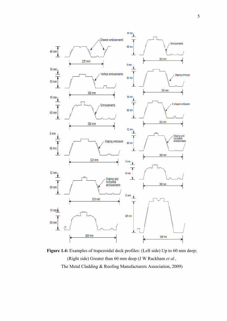
Three generic deck types are commonly available, re-entrant (dovetail),
trapezoidal and so-called deep decking as shown in Figures 1.3 and 1.4. Re-entrant
and trapezoidal are both ‘shallow’ decking – typically between 45 and 90mm deep
overall, and are used to span between 3 and 4.5m. Deep decking is suitable for spans
up to around 9m.

4
Dovetailed rib profiles
Open rib profiles
Figure 1.3: Typical Trapezoidal and Re-entrant deck profiles (First two rows:
Miquel Ferrer, 2006); (Third row: Thomas Mathew Traver, 2002)
.
5
Figure 1.4: Examples of trapezoidal deck profiles: (Left side) Up to 60 mm deep;
(Right side) Greater than 60 mm deep (J W Rackham et al.,
The Metal Cladding & Roofing Manufacturers Association, 2009)

6
A composite form deck has two major functionality which are supporting self
weight and the weight of the unhardened concrete, and construction activites
because this system is usually constructed without propping. After strength
development of concrete up to the designed amount, it will adhere to the steel
sheeting firmly and this will unite this two totally different material to cooperate
together in a composite form and to collaborate in load bearing in an efficient way.
It is an established fact that the efficiency of the composite slabs depends on the
composite action between the steel and the concrete. In order to achieve the required
composite action and to ensure that steel deck acts as tensile reinforcement,
longitudinal shear forces have to be transferred between the steel deck and concrete.
In other words, maintaining composite action requires transfer of load between
the concrete and steel. This load transfer is referred to as bond and is idealized as a
continuous stress field that develops in the vicinity of the steel-concrete interface.
Apart from horizontal shear forces, the imposed bending action can create
vertical separation between the steel and the concrete. Therefore, the profiled
sheeting must resist vertical separation as well as transferring of horizontal shear
forces at the steel-concrete interfaces.
According to experimental tests, it is known that the shear bond generally breaks
down when a ‘slip’ (relative displacement between the decking and the concrete) of
2 to 3 mm has occurred at the ends of the span of normal composite slab sections.
An initial slip, which is associated with the breakdown of the chemical bond, may
occur at a lower level of load. The interlock resistance is usually employed by
means of the performance of the embossments in the deck (which cause the concrete
to ‘ride-over’ the decking), and the presence of re-entrant parts in the deck profile
(which prevent the separation of the deck and the concrete).
Therefore the profiled sheeting should be able to transfer longitudinal shear to
concrete through the interface to ensure composite action of the composite slab. The
adhesion between the steel profile and concrete is generally not sufficient to create

7
composite action in the slab and thus an efficient connection is achieved with one or
several of the following methods (Figure 1.5) :
a) Appropriate profiled decking shape (re-entrant or open trough profile), which
can affect shear transfer by frictional interlock;
b) Mechanical anchorage provided by local deformations (indentations or
embossments) on the surface of decking;
c) Holes or incomplete perforation o the surface of steel sheeting;
d) End anchorage induced by means of welded studs or other forms of local
connection between the concrete and the steel decking;
e) End anchorage by deforming the ribs shape at the end of the steel decking.
Figure 1.5: Typical forms of interlock in composite slabs (Eurocode4, 2001;
Abera Dugassa, 2005)
It must be mentioned that the spacing of the supporting beams, and hence the
span of slab is dependent on the procedure of construction. If the beam spacing was
less than 3.5m, then no temporary shoring is vital during costruction period. This
means that the construction stage governs the design of the steel sheeting. Because
of the shortness of the slab span, the stresses that will develop in the composite slab
8
after hardening of overtopping concrete are not too much or critical. Therefore,
trapezoidal metal decking which have low horizontal shear resistance and ductility
and also have the smallest steel weight per square meter of floor area, are suitable
for short span slabs. For other flooring layouts which the beams are spaced at larger
distances, shoring is necessary to support the steel decking during concreting stage.
Because of the longer slab span, the final state stress that will develop in composite
slab is much more greater. This critical stress will govern the design of such long
composite slabs. In order to establish required high stress transference between steel
and concrete, the steel deckings with high amount of engagement will be employed.
Dovetailed profiles which induce frictional engagement of steel and concrete are
usually utilized in such cases although the give into hand higher steel weight per
square meter of floor area. But they can properly develop horizontal shear resistance
which is essential for long span composite slabs.
1.2 Problem Statement
The structural interaction of concrete slab and steel deck materials in an
optimized manner provides an extremely efficient and economical engineering
solution for flooring systems.
The rapidly increasing adoption of such flooring systems in practice has resulted
in an intensification of the supporting research effort for evaluation and
investigation of their structural performance.
As far as we are concerned about the study of structural and mechanical
behavior of such a system, the investigation of its major controlling modes of failure
is inevitable for more actual modeling of performance of composite slabs.
The strength of the composite diaphragms is majorly influenced by one of the
three limit states, diagonal tension failure of the concrete slab, edge connector
failure (shear stud damage) or shear transfer mechanism failure which result from

9
separation of interconnected layers and slippage of the these two neighboring layers
of concrete mass and steel decking.
The shear bond interaction at the interface of steel deck and concrete can be
separated into three distinctive components, namely, the chemical bonding,
mechanical interlocking, and friction between the two materials. The first
component is the type of bond that is developed through a chemical process as the
concrete cured or hardened. This component of interaction is brittle in nature, and
once it is broken it can not be restored. The mechanical interlocking attains its
strength from the interlocking action between the concrete and the steel decking due
to the presence of embossments or indentations. This action is directly controlled by
the embossment shape and steel deck thickness. Finally, the presence of the friction
between the concrete and the steel deck is due to the presence of internal pressure
between the two materials.
If the connection between the concrete and steel sheet is perfect, that is if
longitudinal deformations are equal in the steel sheet and in the adjacent concrete,
the connection provides complete interaction (perfect bobd or perfobond). If a
relative longitudinal displacement exists between the steel sheet and the adjacent
concrete, the slab has incomplete interaction. The difference between the steel and
adjacent concrete longitudinal displacement can be characterized by the relative
displacement called slip.
It is desirable to take into account the fracture mechanisms of the body of
concrete considering the first and second modes of failure(opening and shear modes)
and also the failure mode concerning to shear bond breakage mechanism(slip or
uplift in steel-concrete contact surface). Investigation of the effect of relative
displacement between the concrete and steel decking which can bring the composite
slab to nonlinear response is the major purpose of this study.
It is an established fact that the interaction between the composite interfaces is
very intricate because stresses and strains in the contact zone between the profiled
metal sheeting and the concrete are complex and depend on many factors.
10
The analysis and design procedures available nowadays must rely inevitably on
experimental data results to account for the concrete-steel interaction parameters
since the bondage between this two totally different layers arises through some
completely various range of processes which can be classified as mechanical,
frictional and chemical bond.
Modeling the actual behavior and performance of shear bond considering
various modes of failure of slab is a pivotal issue and plays a major role in numerical
study of composite action criterion.
Previous experimental investigations provide data for development, calibration
and verification of a model to represent load transfer between reinforcing steel and
concrete. The results of previous analytical investigations provide insight into model
development and implementation within the framework of the finite element
method.
1.3 Aim of Study
Motivations for conducting this research study are as follows:
a) To develop a numerical model that incorporates the precise discontinuous
material behavior and allows for the effects of debonding (horizontal slip and
vertical separation) between the concrete and steel decking.
b) To establish and demonstrate a reliable, and accurate methodology for
numerical analysis of steel-concrete composite slabs.
1.4 Objectives of Study
The objectives of the study can be summarized as follows:

11
a) To develop the nonlinear FE model with damage based mechanics for
composite slabs under flexural loading using cohesive element to simulate the
interaction between concrete and steel deck and to simulate the cracking of
plain concrete considering mixed modes of fracture by means of concrete
damaged plasticity available in ABAQUS software.
b) To perform the quasi-static analysis through explicit dynamics procedure for
the models for simulation and determination of the actual behavior of composite
slab.
c) To evaluate mechanisms of damage, step by step in VULCRAFT steel-concrete
composite slabs when damage initiates and to investigate its propagation
regime.
d) To validate the applicability of the proposed model by comparing the predicted
behaviors with those observed in experimental results obtained by research
work performed at Virginia Tech (Abdullah,2004).
1.5 Scopes of Study
The scopes of works for this research and the restrictions and assumptions are
categorized as follows:
a) The FE model has been developed in 3-D space.
b) This study assumes that steel sheeting is plane and smooth surface without
any indentation or embossment or dimples or welded wire meshing to deck
or any other mechanical interlocking bonds.
c) It has been assumed that not any stud shear connector or steel dowel is
employed in the region of supporting beam hence composite slab span is
totally simply supported.
d) Configuration of empirical data used in this study follows exactly the
experimental works setup carried out by Abdullah (2004).
e) The analyses are just performed for trapezoidal shape cold-formed steel
decks manufactured by Vulcraft of Nucor Research and Development, USA.

150
BIBLIOGRAPHY
Abdollahi A. Numerical strategies in the application of the FEM to RC structures-I.
Computers and Structures 1996;58(6):1171–82.
Abdullah, R. and Easterling, W.S. (2003) Structural evaluation of new VULCRAFT
composite deck profile: Phase II, Report No. CEE/VPI-ST03/01, Virginia
Polytechnic Institute and State University, Blacksburg, Virginia.
An, L. (1993). "Load Bearing Capacity and Behaviour of Composite Slabs with
Profiled Steel Sheet," Ph.D Dissertation, Chalmers University of Technology,
Sweden.
ANSYS Software Documentations; version 11, United States of America.
Bazant ZP, Kim S-S (1979). Plastic fracturing theory for concrete. Journal of
Engineering Mechanics Div (ASCE); 105(3):407–28.
Bode, H., and Sauerborn, I. (1992). “ Modern Design Concept for Composite Slabs
with Ductile Behaviour.” Proceedings of an Engineering Foundation Conference on
Composite Construction in Steel and Concrete 1992, American Society of Civil
Engineers, 125-141.
Bode H, Minas F (1997). Composite slabs with and without end anchorage under
static and dynamic loading. In: Proceedings of engineering conference composite
construction—conventional and innovative.

151
Bode H, Minas F, Sauerborn I (1996). Partial connection design of composite slabs.
Journal of Structural Engineering International; 6(1):53–6.
Calixto JM, Lavall AC, et al (1998). Behaviour and strength of composite slabs with
ribbed decking. Journal of Constructional Steel Research; 46(1–3):211–2.
Crisinel M, Ferrer M, Marimon F, Rossich Verdes M, (2006). Influence of sheet
surface conditions and concrete strength on the longitudinal shear resistance of
composite slabs. In: Prof. J.-M. Aribert retirement symposium proceedings, INSA,
Rennes, 3–5 July 2006.
Crisine, M., Daniels, B. and Ren, P. (1992). “Numerical Analysis of Composite Slab
Behavior,” Proceedings of an Engineering Foundation Conference on Composite
Construction in Steel and Concrete II, ASCE, June, pp. 798-808.
CSSBI. (1996) Standard for Composite Steel Deck, CSSBI 12M - 96, Canadian
Sheet Steel Building Institute.
Daniels, B. J., and Crisinel, M. (1993). “Composite Slab Behavior and Strength
Analysis. Part I: Calculation Procedure.” Journal of Structural Engineering, 119(1-
4), 16-35.
Daniels, B. J., and Crisinel, M. (1993b). “Composite Slab Behavior and Strength
Analysis. Part II: Comparison With Test Results And Parametric Analysis.” Journal
of Structural Engineering, 119(1-4), 36-49.
De Andrade SAL, da S Vellasco PCG, da Silva JGS, Takey TH. Standardized
composite slab systems for building constructions. Journal of Constructional Steel
Research 2004;60:493–524.
Easterling, W. S., and Young, C. S., (1992). "Strength of Composite Slabs." Journal
of Structural Engineering, 118(9), 2370-2389.

152
EN 1993-1-3, Eurocode 3-Part 1.3. Design of steel structures: supplementary rules
for cold-formed thin gauge members and sheeting. European Committee for
Standardisation, 1996.
Evans HR, Wright HD. Steel–concrete composite flooring deck structures. In:
Narayanan R, editor. Steel–concrete composite structures, stability and strength.
London: Elsevier Applied Science; 1988. p. 21–52.
Feenstra, P.H. and Borst, R.D., 1996. “A composite plasticity model for concrete”.
Int. J. of Solids and Struct., 33(5), 707-730.
Ferrer M, Marimon F, Roure F, Crisinel M. Optimised design of a new profiled steel
sheet for composite slabs using 3d non-linear finite elements. In: Proceedings of the
4th European Eurosteel conference on steel and composite structures, Maastricht, 8–
10 June 2005.
Ferrer M, Marimon F, Roure F. Design methodology of profiled steel sheets for
composite slabs by FEM. European Action COST C12: improving buildings’
structural quality by new technologies. In: Proceedings of the international
conference, Innsbruck, 20th–22 January 2005.
Ferrer M (2006), Numerical and experimental approach to the interaction between
steel sheet and concrete to improve shear resistance of composite slabs. Doctoral
thesis. Technical University of Catalonia (UPC). Barcelona.
F.H.Wittmann (1993), Numerical Models in Fracture Mechanics of Concrete, Swiss
Federal Institute of Technology, Zurich.
Goodman JR, Popov P. (1968) Layered beam systems with interlayer slip. Journal of
the Structural Division; 2535–47.
Hoffmeister, B. and Sedlacek, G. (1996). “Plastic Hinge Theory for Composite
Floors and Frames,” Proceedings of the Engineering Foundation Conference on
Composite Construction in Steel and Concrete III, ASCE, pp. 887-897.

153
Izzuddin B. A., Tao X. Y. and Elghazouli, A. Y. (2004). “Realistic Modeling of
Composite and Reinforced Concrete Floor Slabs under Extreme Loading I:
Analytical Method.” Journal of Structural Engineering, 130(12), 1972-1984.
J W Rackham et al (2009)., The Metal Cladding & Roofing Manufacturers
Association, Composite Slabs and Beams using Steel Decking: Best Practice for
Design and Construction (Revised Edition), MCRMA Technical Paper No. 13 SCI
Publication No. P300.
Jeong YJ (2005), Partial-interactive behaviors of steel–concrete composite bridge
deck. Ph.D. Thesis. Korea: Yonsei University.
Johnson, R. P. (1994). Composite Structures of Steel and Concrete, Vol. 1: Beams,
Slabs, Columns, and Frames for Buildings, Blackwell Scientific Publication,
Oxford.
Juozas Valivonis (2006), “Analysis of behaviour of contact between the profiled
steel sheeting and the concrete”, Journal of civil engineering and management.
Kitoh, H. and Sonoda, K. (1996). “Bond Characteristics of Embossed Steel
Elements,” Proceedings of the Engineering Foundation Conference on Composite
Construction in Steel and Concrete III, ASCE, pp. 909-918.
Luttrell, L. D. (1987). “Flexural Strength of Composite Slabs” Composite Steel
Structures-Advances, Design and Construction, Narayanan, R., Ed., Elsevier,
London, 106-115.
Makelainen P, Sun Y (1999). The longitudinal behaviour of a new steel sheeting
profile for composite floor slabs. Journal of Constructional Steel Research;49:117–
28.

154
Marˇciukaitis G, Valivonis J, Vaˇskeviˇcius A (2001). Analysis of behaviour of
composite elements with corrugated steel sheeting. Civil Engineering
(Statyba);7(6):425–32.
Marˇciukaitis G, Jonaitis B, Valivonis J (2006). Analysis of deflections of composite
slabs with profiled sheeting up to the ultimate moment. Journal of Constructional
Steel Research; 62:820–30.
Menrath H, Haufe A, Ramm E (1998). A model for composite steel-concrete
structures. In: de Borst R, Bicanic N, Mang H, Meschke G, editors. Proceedings to
the EURO-C. Rotterdam: Balkema; 1998. p. 33–42.
Nik Mat Bin Udin (2006). Modeling of Shear Bond in Composite Slab Using
Interface Element. B.Eng. Thesis. University of Technology Malaysia.
Ong, K.C. and Mansur, M.A. (1986). “Shear-Bond Capacity of Composite Slabs
Made with Profiled Sheeting,” The International Journal of Cement Composites and
Lightweight Concrete, Vol. 8, No. 4, pp. 231-237.
Patrick, M., and Bridge, R. Q. (1992). "Design of Composite Slabs for Vertical
Shear." Proceedings of an Engineering Foundation Conference on Composite
Construction in Steel and Concrete II, American Society of Civil Engineer, 304-
322.
Patrick, M. (1990). “Long-Spanning Composite Members with Steel Decking,”
Proceedings of the Tenth International Specialty Conference on Cold-Formed Steel
Structures, University of Missouri- Rolla, pp. 81-102.
Phuvoravan K. and Sotelino E. D. (2005). “Nonlinear Finite Element for Reinforced
Concrete Slabs.” Journal of Structural Engineering, 131(4), 643-649.
Pi YL, Bradford MA, Uy B (2006). Second order nonlinear inelastic analysis of
composite steel–concrete members. II: Applications. Journal of Structural
Engineering, ASCE;132(5):762–71.

155
Poh, K. W. and Attard, M. M. (1993). “Calculating the Load-Deflection Behaviour
of Simply- Supported Composite Slabs with Interface Slip,” Engineering Structures,
Vol. 15, No. 5, pp. 359-367.
Porter ML, Ekberg CE(1976); Design recommendations for steel deck floor slabs.
Journal of the Structural Division, ASCE;102(ST 11): 2121–35.
Porter ML, Ekberg CE, Greimann LF, Elleby HA (1976). Shear bond analysis of
steel deck reinforced slabs. Journal of the Structural Division, ASCE;102(ST
12):2255–68.
Porter ML, Ekberg Jr CE. (1971) Investigation of cold-formed steel-deck reinforced
concrete floor slabs. In: Yu W-W, editor. First specialty conference on cold-formed
steel structures. Rolla: University of Missouri-Rolla; p. 179–85.
Porter, M. L., and Ekberg, C. E. (1977). “Behavior of Steel-Deck-Reinforced Slabs.”
Journal of the Structural Division, Volume 103, No. 3, March 1977, 663-677.
Porter, M. L. and Greimann, L. F. (1984). “Shear-Bond Strength of Studded Steel
Deck Slabs,” Proceedings of the Seventh International Conference on Cold-Formed
Steel Structures, University of Missouri-Rolla, pp. 285-306.
Roeder, C. W. (1981). “Point Loads on Composite Deck-Reinforced Slabs,” ASCE
Journal of the Structural Division, Vol. 107, pp. 2421-2429.
Rondal J, Moutafidou A. (1997) Study of shear bond in steel composite slabs. In:
Proceedings of engineering conference—composite construction —conventional and
innovative.
Schuster RM. (1972). Composite steel-deck-reinforced concrete systems failing in
shear-bond. Preliminary Report ninth Congress IABSE Amsterdam. Zurich: IABSE.
156
Schuster, R. M. (1970). "Strength and Behavior of Cold-Rolled Steel-Deck-
Reinforced Concrete Floor Slabs," Phd Dissertation, Iowa State University, Ames,
Iowa.
Schuster, R. M. and Ling, W.C. (1980). “Mechanical Interlocking Capacity of
Composite Slabs,” Proceedings of the Fifth International Specialty Conference on
Cold-Fromed Steel Structures, University of Missouri-Rolla, pp. 387-407.
Schuurman RG (2001). The physical behaviour of shear connections in composite
slabs. Doctoral thesis. Technische Universiteit Delft.DUP Science, Delft.
Schuurman, R. G. and Stark, J.W.B. (1996). “Longitudinal Shear Resistance of
Composite Slabs – To a Better Understanding of the Physical Behaviour”
Proceedings of the Engineering Foundation Conference on Composite Construction
in Steel and Concrete III, ASCE, pp. 89-103.
Sebastian, W. M., and McConnel, R. E. (2000). “Nonlinear FE Analysis of Steel-
Concrete Composite Structures”. Journal of Structural Engineering. 126(6): 662-674.
Seleim, S. S., and Schuster, R. M. (1985). “Shear-Bond Resistance of Composite
Deck- Slabs.” Canadian Journal of Civil Engineering, 12(316-323).
Shanmugam, N. E. (2002), Finite element modeling of double skin composite slabs.
Department of Civil Engineering, National University of Singapore, Singapore.
Shanmugam, N.E., Kumar G. and Thevendran V. (2002). “Finite element modeling
of double skin composite slabs”. Finite elements in analysis and Design. 38, 579-
599.
Soh CK, Chiew SP, Dong YX (2002). Concrete–steel bond under repeated loading.
Magazine of Concrete Research; 54(1):35–46.
Soh CK, Chiew SP, Dong YX (1999). Damage model for concrete–steel interface.
Journal of Engineering Mechanics ASCE; 125(8):979–83.

157
Stark, J. (1978). “Design of Composite Floors with Profiled Steel Sheet,” Forth
International Specialty Conference on Cold-Formed Steel Structures, University of
Missouri-Rolla, pp. 893-922.
Tenhovuori A, Karkkainen K, Kanerva P. (1996) Parameters and definitions for
classifying the behaviour of composite slabs. In: Proceedings of on engineering
foundation conference—composite construction in steel and concrete..
Tenhovuori AI, Leskela MV. (1998) Longitudinal shear resistance of composite
slab. Journal of Constructional Steel Research; 46(1–3):228.
Terry, A.S. (1994). The Effects of Typical Construction Details on the Strength of
Composite Slabs, M.S. Thesis, Virginia Polytechnic Institute and State University,
Blacksburg, Virginia.
Veljkovic, M. (1994) Interaction between Concrete and Sheeting in Composite
Slabs. S-971 87 LULEA, Lulea University of Technology, Division of Steel
Structures, Lulea, Sweden.
Veljkovic, M. (2000). “Behavior and Design of Shallow Composite Slab,” Draft for
the Proceedings of an Engineering Foundation Conference on Composite
Construction in Steel and Concrete IV, ASCE
Veljkovic, M. (1995). "Longitudinal Shear Capacity of Composite Slabs." Nordic
Steel Construction Conference '95, Malmo, Sweden.
Veljkovic, M. (1996a). “Behaviour and Resistance of Composite Slabs,” Phd Thesis,
Lulea University of Technology, Lulea, Sweden.
Veljkovic, M. (1994). “3-D Nonlinear Analysis of Composite Slabs,” DIANA
Computational Mechanics ’94, Eds: G.M.A. Kusters, M. A. N. Hendricks, pp. 394-
404.

158
Widjaja, B.R. and Easterling,W. S. (1996). “Strength and Stiffness Calculation
Procedures for Composite Slabs,” 13th International Specialty Conference on Cold-
Formed Steel Structures, University of Missouri-Rolla, pp. 389-401.
Yam, Lloyd C. P. (1981). “Design of Composite Steel-Concrete Structures” Surrey
University Press, London.
Yazdani S, Schreyer HL. (1990) Combined plasticity and damage mechanics model
for plain concrete. J Engineering Mechanics (ASCE); 116(7):1435–50.
Young, C.S. (1990). Effects of End Restraint on Steel Deck Reinforced Concrete
Floor Systems, M.S. Thesis, Virginia Polytechnic Institute and State University,
Blacksburg, Virginia.