nonel'l - defense technical information center · d6,ensified biomass as an alternative ......
TRANSCRIPT
AO-A063 317 CONSTHJCTION ENSINIERINS RESEARCH LAO (ARSW) a.AA:ffi SL p#S jq_DENSIFIED RIOMAlS AS AN ALTERATIVE ARM HEATING AD POMP KUN-MiCulNM 0O S A HATHAWAY. .J S LINP D MAHION
U4CLASSIFICO cIML-TR-g-INI
EME
NONEl"'l
MI1RCO1 1.0 OLU *O IIIHARNA11A1 BUEA1O S IAN I] s
1.8
MICROCOPY RESOLUTION TEST CHART
NATIONAL BUREAU UT SIANDARDS 1U5l A
constructionUie ttsAmengineeringneerresearch March 1980
laboratory
DENSIFIED BIOMASS AS AN ALTERNATIVEARMY HEATING AND POWER PLANT FUEL
> byS. A. Hathaway
J. S. LinD. Mahon
T. MagrinoK. Duster
DTICAPRCL O F
A
8Opprovet 4pubic~22 distriajo~hnited
The contents of this report are not to be used for advertising, publication, orpromotional purposes. Citation of trade names does not constitute anofficial indorsement or approval of the use of such commercial productsThe findings of this report are not to be construed as an official Departmentof the Army position, unless so designated by other authorized documents.
DESTROY THIS REPORT WHEN ITIS NO LONGER NEEDEDDO NOT RETURN IT TO THE ORIGINA TOR
I1 _ _ _ _ _ _ _ _ __ _ _ _ _ _ _ _ _
Illll '--
* ~ ~ ~ ~ - w, fatr,. ,j , m a eI ^to c. (wnen Lisce -etcrwuJ
REPORT DOCUMENTATION PAGE READ INSTRUCTIONS
I BEFORE COMPLETING FORMCELR E5 12. GOVT ACCESSION NO 4T'S CATALOG NUMBER
D6,ENSIFIED BIOMASS AS AN ALTERNATIVE ARMY HEATING FIA
AN EOE PL N ANDL AD RS 10 R GR M E E EN P OECT S
U.W ARM AEA4WRKUN T NUMBER
CONSTRUCTION ENGINEERING RESEARC LABORATOR
P.O. Box 4005,n Champaign, IL35 6182 3_____________
11. CONTROLLING OFFICE NAME AND ADDRESS ft) R"ORg4~T'O
-13 NM13MER OF' PAGES
14. MONITORING AGENCY NAME & ADDRESSII different from Controlling Office) IS. SECURITY CLASS. (of this. report)
Unclassified
15a. DECLASSI FICATION/ DOWNGRADINGSCHEDULE
16. DISTRIBUTION STATEMENT (of thie Report)
Approved for public release; distribution unlimited.
17. DISTRIBUTION STATEMENT (of the abetract entered in Block 20, It different from Report)
It. SUPPLEMENTARY NOTES
Copies are obtainable from National Technical Information ServiceSpringfield, VA 22151
19. KEY WORDS (Continue on rev roe side It necessary end Identify by block number)
woodbiomass energy
2(k AWVCr sioravonw seye N neesmy mi identIfy by block number)
This investigation evaluated the technical and economic potential of using densifiedbionfass (principally wood pellets) as a coal substitute in Army heating and powerplants. The report reviews Department of Defense (DOD) experience with and tests of
L ~ wood pellets; production of wood pellets (excluding silvicultural aspects); handling,storing, and feeding; combustion; major environmental considerations; and economicsj of use.
DD, F0 1473 go-nIowo nOF 1es is "Pn UNCLASSI FIED/'e SEcumITY CLASSIFICATION OF THIS PAGE (Uhe' Dote Entered)
SECURITY CLASSIFICATION OF THIS PAGEI(Vhn Dlte Bote ed)
Block 20 continued.
It is concluded that wood pellets appear to be a viable alternative to coal instoker-fired Army heating and power plants, but that their use will entail some loss ofboiler fuel-to-product conversion efficiency and some sacrifice of boiler maximumcontinuous rating.
The report recommends using wood pellets wherever technically and economicallyfeasible, establishing standard technical specifications to aid in wood pellet procurement,and monitoring installation-scale wood pellet systems continuously both to validate thewood pellet concept over long-term use and to identify technological gaps andopportunities associated with wood pellet use.
The report contains an analysis of wood pellet,;' characteristics and ability to flow,and a design for a 250-ton (225-MT) bin and feeder system.
q
ji 7UNCLASSIFIEDSECURITY CLASSIFICATION OF THIS PAGE(When Date Entored)
7Tm.-.m
FOREWORD
This investigation was conducted by the I.S. Army Construction EngineeringResearch Laboratory ICERL) for the Office, Chief of Engineers IOCE) under FundingAuthorization Document MP-tERL-79-1 and Funding Allotment 7635, Change 3. Mr.R. D. Winn tDAEN-MPO-U) served as the OCE Technical Monitor. and the CERLPrincipal Investigator was Mr. S. A. Hathaway of the Energy and Habitability Division(CERL-EH).
Data provided in the Appendices were prepared by Jenike and Johanson, Inc., North3illerica, MA, under contract 79342.
Appreciation is extended both to the numerous heating and power plant operatingpersonnel whose expertise and exceptionally professional teamwork were instrumentalin successfully completing the tests reported here, and to the following personnel fortheir generous cooperation and invaluable assistance during this investigation: Dr. H.Balbach, CERL; Mr. E. Bocian, Fort Benjamin Harrison, IN; Mr. P. Dubenetzky, Stateof Indiana, Mr. D. Ekstrom, Rock Island Arsenal, IL; LTC J. Flora, Facilities Engineer,Fort McCoy, WI; Mr. J. Galyon, Tbnnessee Woodex, Inc.; Mr. G. Grazier, State ofIndiana; Mr. S. Helms, U.S. Army Facilities Engineering Support Agency; Mr. J.Herschy, Fort Benjamin Harrison, IN; Mr. P. Houze, Fort Benjamin Harrison, IN; Mr.J. Jones, Fort McCoy, WI; Mr. H. Lewin, Rock Island Arsenal, IL; Mr. S. Mason, HQ,U.S. Army Training and Doctrine Command; Mr. D. Mueller, Rock Island Arsenal, IL;Mr. H. Musselman, OCE; Mr. D. Neitzel, Fort McCoy, WI; CPT R. Oifenbuttel, lyndallAFB, FL; LTC G. Rutledge, Facilities Engineer, Fort Benjamin Harrison, IN; Mr. D.Schaub, Guaranty Performance Co., Independence, KS; Mr. C. Smith, OCE; Mr. V.Vaughn, Deputy Facilities Engineer, Fort Benjamin Harrison, IN; Mr. B. Wasserman,OCE; Mr. J. Weigl, HQ, U.S. Army Forces Command; Dr. H. Wilcox, U.S. Navy OceanSystems Center, San Diego. CA.
Administrative support was provided by Mr. R. G. Donaghy, Chief, CERL-EH. COLL. J. Circeo is Commander and Director of CERL, and Dr. L. R. Shaffer is TechnicalDirector.
Accession For
NTISDDC TILB
3,A
CONTENTS
DD FORM 1473 1FOREWORD 3LIST OF TABLES AND FIGURES 6
1 IN TRO D UCTIO N ......................................................... 9Background
ObjectiveApproach
2 DOD TESTS USING DENSIFIED BIOMASS ................................ 10GeneralKingsley AFB, ORFort McCoy, WIRock Island Arsenal, ILFort Benjamin Harrison, INSummary
3 DENSIFIED BIOMASS PRODUCTION ..................................... 22GeneralProduction ProcessEquipment and FunctionsEnergy AnalysisProduct CharacteristicsEconomics of ProductionSummary
4 HANDLING, STORING, AND FEEDING ................................ 30GeneralReceiving Raw Material for Wood Pellet ProductionWood Pallet Storage Vesel Design
Use of Wood Pellets in Existing Coal BunkersSummary
5 COMBUSTION ................................................... ... 39GeneralFuel Composition and CharacteristicsFeedingReactivityCombustion StoichiometryFlame Temperature
Surface EffectsAuxiliariesResponse and Turndown
ControlsRng Mixtures of Wood Pellets and Coal
Summafry
4
.........

6 ENVIRONMENTAL CONSIDERATIONS ............................. .. 48GeneralWoter
AirSummary
1 ECONOMICS OF DENSIFIED BIOMASS USE...........................5SOGeneralEconomnic Data and AssumptionsSubstituting Wood Pellets for Sulphur-Compliant Coal
Cost of Wood Pellets
S CONCLUSIONS................................................... 54
9 RECOMMENDATIONS ............................................. 55
REFERENCES 56APPENDIX A: Wood Pellet Bin and Feeder Design 58APPENDIX 8: Laboratory Analyses of Wood Pellets 62ANNEX 1: Test Data 74
DISTRIBUTION
5~-
TABLES
Number Pa"
I Coal Properties. Fort Benjamin Harrison, IN 18
2 Woodex Properties, Fort Benjamin Harrison. IN 18
3 Sieve Analysis of Woodex, Fort Benjamin Harrison. IN 18
4 Sieve Analysis of Wood Dust, Fort Benjamin Harrison, IN 19
5 Energy Analysis of 120 Tons/Day (108MT/Day) WoodPellet Operation 26
6 Chemical Analysis of Fuels 27
7 FY80 Economics of Wood Pellet Production(120 Tons/Day [ 108 MT/Day ] Input) 29
8 Annual Cost Analysis of 120 tons/day (108 MT/day)Wood Pellet Production 30
9 General Material Properties Affecting Handling 31
10 Basic Bulk Flow Properties of Solids 37
11 Combustion Performance Table for Solid Fuel Properties 40
12 Calculation of Stoker Speed for Coal 41
13 Comparative Combustion Calculations -Coal %. Wood Pellets 44
14 Composition of Coal and Wood Ash 49
15 Economic Data 50
16 Cost Comparison for Scenario 1 52
17 Cost Comparison for Scenario 2 53
BI Bin Dimensions (0.0 Hours Storage Time) 62
B2 Bin Dimensions (65.0 Hours Storage Time) 63
B3 Bulk Density 63
B4 Aged Carbon Steel (0.0 Hours Storage Time at Rest) 64
B5 30442B Stainless Steel (0.0 Hours Storage Time at Rest) 64
116 304-#2B Stainless Steel 165.0 Hours Storage Time at Rest) 65
~6
FIGURES
Number Page
I Conifer Burner" of Type being Implemented at Fort McCoy. WI 13
2 Boiler Tested at Fort Benjamin Harrison, IN 15
3 Bunker Cross Section, Fort Benjamin Harrison, IN 16
4 Relation of Fuel Bed Depth to Particulate Emissions
From Wood-Fired Boilers 20
5 Wood Pellet Production Process 23
6 Wood Chip Storage Concept 13S
7 Flow/No-Flow Conditions in Gravity Mass Flow Vessel 34
8 Wood Pellet Storage Bin 35
9 Wood Pellet Feeding Apparatus 35
Al Modular Bin Design 59
A2 Belt Feeder Design 60
A3 Belt Feeder Configuration 61
BI Delta and Phi Vs. Consolidating Pressure 65
B2 Strength Vs. Consolidating Pressure 66
B3 Shear Load Vs. Normal Load for 3.75-in. Cell
(0.00 to 12.00 Ib 67
B4 Shear Load Vs. Normal Load for 3.75-in. Cell
(0.00 to 30.00 Ib) 68
B5 Shear Load Vs. Normal Load for 2.50-in. Cell
(0.00 to 60.00 Ibi 69
B6 Log Vs. Log Consolidating Pressure 70
B7 Shear Stress Vs. Normal Stress-304 2B SS
(0.00 to 600.00 psI) 71
B8 Shear Stress Vs. Normal Stress-304 2B SS
(0.00 to 480.00 psf) 72
B9 Shear Stress Vs. Normal Stress -Aged Carbon Steel
(0.00 to 600.00 psf) 73
_7
A ,

FIGURES
Number Page
IBI Mass Flow Bins 75
IB2 Funnel Flow Bins 76
IB3 Expanded Flow Bins 77
I8
, llb " , m ,0- 'T
DENSIFIED BIOMASS AS AN Energy Plan. :' Coal is now Waining preftrk-nc as a priALTERNATIVE ARMY HEATING AND mary fuel in both new and convertld Army heating
POWER PLANT FUEL ant power plants. The Army coal conversion effortprobably will empLasize proven stoker-firing tech-
nologies, since nearly all installations have neither
the technical need for, nor the economy of scale to
1 INTRODUCTION support, large pulverized coal-firing systems.4 The
average Army central power plant has less than 200
MBtuh 159 MWt) capacity, consists of multiple boilers
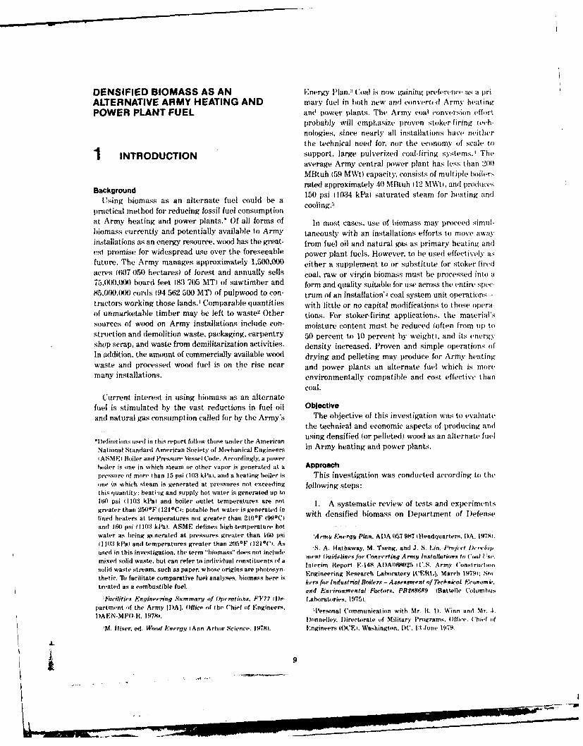
Background rated approximately 40 MBtuh (12 MWti, and producesUsigom s a150 psi (1034 kPal saturated steam for heating andUsing hiomass as an alternate fuel could be a
practical method for reducing fossil fuel consumption cooling.
at Army heating and power plants.* Of all forms of In most cases, use of biomass may proceed simul-biomass currently and potentially available to Army taneously with an installations efforts to move away
installations as an energy resource, wood has the great- from fuel oil and natural gas as primary heating andest promise for widespread use over the foreseeable power plant fuels. However, to be used effectively as
future. The Army manages approximately 1,500,000 either a supplement to or substitute for stoker-firedacres 1607 050 hectares) of forest and annually sells coal, raw or virgin biomass must be processed into a75,000,0() board feet 183 705 MT) of sawtimber and form and quality suitable for use across the entire spec-
85,000,00)0 cords (94 562 500 MT) of pulpwood to con- trum of an installation's coal system unit operations-
tractors working those lands.' Comparable quantities with little or no capital modifications to those opera-of unmarketable timber may be left to waste2 Other tions. For stoker-firing applications, the material's
sources of wood on Army installations include con- moisture content must he reduced (often from up tostruction and demolition waste, packaging, carpentry 50 percent to 10 percent by weight), and its energy
shop scrap, and waste from demilitarization activities, density increased. Proven and simple operations of
In addition. the amount of commercially available wood drying and pelleting may produce for Army heating
waste and processed wood fuel is on the rise near and power plants an alternate fuel which is more
many installations. environmentally compatible and cost effective than
coal.Current interest in using biomass as an alternate
fuel is stimulated by the vast reductions in fuel oil Objective
and natural gas consumption called for by the Army's The objective of this investigation was to evaluate
the technical and economic aspects of producing anti
*Definitions used in this report follow those under the American using densified (or pelleted wood as an alternate fuel
National Standard American Society of Mechanical Engineers in Army heating and power plants.
I ASME) Boiler and Pressure Vessel Code. Accordingly. a power
boiler is one in which steam or other vapor is generated at a Approachpressure of more than 15 psi (103 kPaI. and a heating boiler is This investigation was conducted according to theone in which steam is generated at pressures not exceeding following steps:this quantity; heati-ig and supply hot water is generated up to160 psi 11103 kPa} and boiler outlet temperatures are not 1. A systematic review of tests and experimentsgreater than 250'F 1t21C1: potable hot water is generated inlined heaters at temperatures not greater than 21(10F 990C with densified biomass on Department of Defense
anti 160 psi 1103 kPal. ASME defines high-temperature hot -
water as being gnerated at pressures greater than 160 psi 'Army erg.y Plan. ADA 057 987 1 Headquarters. I)A. 19781.i1103 kPat and temperatures greater than 2051F 12100i. As '. A. Hathaway, M. Tseng. and J. S. in. Project Defweop
used in this investigation, the term "hiotmass" does not includemixed solid waste, but can refer to individual constituents of a Inerieor E-14,ering Arm y onst( sc.solid waste stream, such as paper, whose origins are photosyn- Eneri Reer F.-148, AA 7M2 I. ary stonthetic. lTo facilitate comparative fuel analyses. hiomass here is Engineering Rtesearch Laboratory ICER[,I. March 1979i: Stb-
atd My facilit com ati e fue a kers for Industrial Boilers - Assessment of Tech nicat Ecotomir,treated as a combustible fuel. and Eni'ironmental Factors, PRWt8689 fBattelle Columbus
'Facilities Engineering Summary of Operations. FY77 le- I,ahoratories. 19751.partment of the Army ll)AI. Office of the Chief of Engineers., Personal Communication with Mr. It. t). Winn and Mr. ..)AEN.MPO.R. 19781,. Donnelley. Directorate of Military Programs. t)ffirt,. Chief -f
M. ffiser. ed. Wood Energy iAnn Arbor Science. 19781. Engineers (CE), Washington. DC. 1:1 ,June 1979.
ft 9
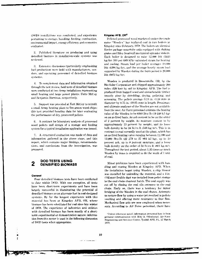
I )()) instalha ions was cmducted, and experience Kingsley AFB, OROpertaining to stirage, handling, feeding, combustion, leted Iprocesse d wood market ed under the t rade
environmental impact, energy efficiency, and economics name "Woodex" has replaced coal in two boilers at
evaluate(I. Kingsley since February. 1978 The boilers are idlentical
Keeler package watertube units equipped with shakinv2. Published literature on producing antd using grates and Riley frontwall mechanical spreader stokers.
densified biomass in installation-scale systems was Each boiler is designed to raise 12,000 Ibh 15443
reviewed. kg/hr I)( psi (689 kPal saturated steam for heatingemphasizing and cooling. Steam load per boiler averages 10 ,000)
:1. Extensive dliscuissions (particularly emhszi bIh {4:96 kg/hrt, and the average hourly steam load
luel )ro(uction) were held with manufacturers, ven-
dors, ant operating persmnnel of densified biomass supported by Woodes (uring the urn period is 20091
systersl. lIh 19072 kg/hri.systems),
Woodex is produced in Brownsville, OR, by the4. 'lb complement data and information obtained RoSlrCroainadsipdapoiaey2X
through the test review, field tests of densified biomass ils 2oknbraio nsed ar.mtel 2s
were conducted at two Army installations representing proluced from hogged woodl an unmarketaB timer
small heating andi large power plants: Forts McCoy (mostly pinel by shredding. (Irying. pelleting. and
and Benjamin hlarrison, respectively, screening. The pellets average 0.13 in. (3.18 mml in
5. Support was lrovidetd at Fort McCoy to retrofit diameter by 0.75 in. (19.05 mm) in length. Proximate
a small Army heating plant to fire green wood chips: and ultimate analyses of the Woodex are not available
this test provided baseline data for later evaluating from the user. Air Force personnel estimate the heating
the performance of dry, processed pellets, value of the Woodex to be 8:36) Btu/l) (19 440 k.Jkgl
on an as-fired basis, its ash content to be on the order
6. A contract for laboratory analysis of processed of 2 percent by weight, its moisture content to be
wood pellets and design of a storage and feeding approximately 13 percent by weight, and its loose
system for a typical installation application was issued. bulk density to be 34 lb/cu ft t544 kg/m:. This is incontrast to coal normally used at the plant, which has
7. A structured evaluation was made of data and an as-fired heating value ranging between 11,0(9) and
information gathered in the above steps, and this 12,000 Btu/lb (22 579 to 27 904 kJ/kg., up to 1)report, which contains major findings, recommenda- percent ash, up to 8 percent moisture, and a loosetions, and conclusions from the investigation, was bulk density on the order of 50 1b/cu ft 181) kg/ mI.prepared. Throughout the test period, about 1.35 times as much
Woodex by mass is required to do the work of I unitof coal.
DOD TESTS USING Minor problems have been experienced with han-
2 DENSIFIED BIOMASS dling and storing Woodex at Kingsley AFB. When
the installation began using Woodex. a chip blower
General was installed for unloading the material, and a 4-in.
Four densified biomass tests have been conducted (102-mm) flexible duct was installed from pellet storage
to (late within 1)01D. With one exception, all tests to the coal chute cleanout hatch. The coal suppl3 was
have been short-term experiments and have been cut off by closing the coal silo entrance to the coal
largely successful in illuminating the potential of chute. Early on. there was a tendency for minor
densified biomass as an alternate fuel in coal-designed bridging of the Woodex in the coal chuested impt
systems. By far the longest experience with this to restore flow by using a water jet resulted in pellets
material has been at Kingsley AFI3, OR, where swelling and offering more resistance to free flow.
Iiomass has been substituted for coal since late winter Mechanical flow aids are now employed when neces-
of 1978. The experience of industries anti utilities sary. According to Air Force personnel, there have
with densified biomass has been mostly of a short-term experimental or demonstration nature; informa- 'Unle'ss otherwise no(ed. information iesented hen, is fr.ni
peitshnal communication with MAJ It, ( Ilfian 1 te. Air For'ettion from this sector is used in the following discussion Engineerin anti Services Center, T.ndall AVtI,. VI,. 2, Marchof DO) tests when appropriate. 1979.
* 10
been no major problems with open storage of Woodex, A baghouse, originally installed for particulate removaleven when the material is exposed to rainfall over when coal was fired, is bypassed when Woodex isshort periods. Personnel have observed some break- used. Although never tested, particulate emissionsdown of Woodex due to handling, but have considered from Woodex are apparently compliant, as evidencedthis a trivial concern, by a clear smoke plume.
According to Air Force personnel, furnace and boiler Use of Woodex as a coal substitute at Kingsleyperformance has been satisfactory when firing Woodex AFB has been economically advantageous. The fuel is
as a complete substitute for coal during typical steam purchased at a delivered cost of $36.50/ton $40.24/iMT,loads of 83 percent. Each of the two boilers firing which includes $12.50/ton I$13.78/MT) shipping. TheWoodex consumes about 12 tons/day 110.8 MT/day) delivered cost of coal is $48.00/ton ($53.92/MTi. Onfuel, and, although 35 to 40 percent more Woodex an energy-unit basis, the delivered cost of Woodex isthan coal on a mass basis must be fired for equal $2.17/MBtu )$2.07/kJ), while that of coal is $2.18/MBtufurnace heat release, there has been no difficulty in ($2.06/kJt. Cost of Woodex f.o.h, from the site ofincreasing the feed rate to achieve this. The major production is $1.4"3/MBtu l$1.36/kJi. Although theoperational changes made to accommodate Woodex delivered costs of Woodex and coal are essentially thefiring were to reduce combustion air by one-third, same on an energy-unit basis, Woodex has, at Kingsleyreduce induced draft by two-thirds, increase the stoker AFB, the additional economic advantages of reducedspeed and discharge feed angle, and increase the fuel boiler maintenance and repair, reduced fly ash ban-feed rate. Throughout the burn period, an ash bed dling, reduced ash removal, and the avoided cost ofdepth of 1 in. (25.4 mm) is maintained over the shaking air pollut:-n control system operation. According togrates to protect grate material from thermal stress Air Force personnel, boiler cleaning is easier and itsdue to radiant heat. Minor problems have been frequency reduced ninefold 1from three times perexperienced with underfire air velocities occasionally shift to once daily). When firing coal, the ash silo hadbeing too high, resulting in partial fluidization of the to be discharged once weekly, but when using Woodex.fuel bed and entrainment of fines into the combustion this task is performed once every 4 to 6 weeks becausegases, and with fines in the fuel-fines which readily of reduced fuel ash content. In addition, plant personnelentrain when mechanically fed to the furnace, estimate a savings of at least 800 man-hours per year
in baghouse maintenance and of an undetermined but
When a blend of Woodex and coal is fired, however, large amount of costly electrical power in baghousesignificant slagging occurs, along with sometimes operation. Although these savings have not beensevere clinker formation, because of the difference in quantified, it is clear that Woodex can have a distinctthe burning temperatures between Woodex and coal. economic advantage over coal. This advantage couldAccordingly, personnel recommend against firing a grow significantly if the avoided costs of installing,fuel mixture. operating and maintaining a flue gas desulphurization
system are considered.Although fugitive dust is a problem when using
Woodex, Air Force personnel ar, optimistic that theenvironmental impact of using Woodex will be less Fort McCoy, Wlthan that of coal. Noticeable dust emissions occur as Woodex replaced coal in several small heating plant,;Woodex is delivered to a receiving pit before being at Fort McCoy, WI, during tests conducted in Marchmoved to the silo. Delivery of the fuel from the silo to 1978, and excess test pellets were used in one heatingthe boiler is essentially an enclosed operation and plant as a coal substitute for several months thereafter.does not produce a dust problem. Plant personnel The boilers tested were small in contrast to the largefeel that use of Woodex has resulted in an improved central installation power systems at which otherworking environment because wood fines are less tests and demonstrations were conducted. The heatingtoxic and generally cleaner than coal dust. plants were rated from 0.25 to about 2.0 MBtuh 10.07
to 0.59 MWtJ, individually supplying heating steamKingsley AFB implemented Woodex largely to to barracks, maintenance facilities, shops, and admin-
comply with U.S. Environmental Protection Agency istrative activities. The units tested were firetube(USEPA) emission requiremenL. Since Woodex con- boilers equipped with an auger-feed. underfeed retorttains only a negligible amount of sulphur, its use stoker in a rectangular, refractory-faced combustionresults in essentially no emission of sulphur oxides. chamber.
__ _1
j "

The Woodex tested was produced by Tennessee countered when firing Woodex during normal boilerWoodex, Inc.. Knoxville, TN, and shipped in covered operation, no instrumentation and monitoring equip-
dump, trucks to Fort McCoy. The fuel was manufactured ment was used other than what was in-place in the
largely from hogged pine and pine bark by shredding, plants. When Woodex was substituted for coal, the
drying, and pelleting. A final screening stage to remove heating plants were able to sustain full load operation
fines from the Woodex product was not in operation and adequate response to fluctuations in steam demand
at the time of manufacture. Proximate and ultimate over the short term. Stack gas content of CO ranged
analyses of the Woodex were not available, but Army from 4 percent to 8 percent, that of C02 ranged from
personnel estimated the heating value of the Woodex 11 percent to 16 percent, and temperatures ranged be-
to be 8250 Btu/lb 1.1 185 kJ/kg on an as-fired basis, r' tween 600OF 3160C and 650F t:W30C (approximately
its ash content to be on the order of 2 percent by 150*F (660C] higher than when firing coal. Relatively
weight, its moisture content to be approximately 12 large flame travel was observed when firing Woodex.
percent by weight, and its loose bulk density to be 39 but there was no apparent problem of impingement
Ib/cu ft I(08 kg/m:4. Coal normally used at Fort McCoy or carryover to the firetube section, It was felt that
has an as-fired heating value of about 11,000 Btu/lb combustion could be improved by elevating the back-
(22 579 kI/kg . tip to 12 percent ash, up to 7 percent wall overfire air nozzles and by providing finer controlmoisture, and a loose bulk density on the order of 50 over overfire and underfire air. When blends of Woodex
lb/cu ft (801 kg/m:). During the tests, it was observed and coal were fired, combustion and boiler performance
that from 35 to 40 percent more Woodex than coal (by again was satisfactory over the short term; however,mass) was required to do a similar amount of work. the fuel bed displayed a strong tendency to clinker.
and generation of smoke increased. As discussed later.
Virtually no problems were encountered in handling this was attributed to the technical inability to optimizeand storing the Woodex at Fort McCoy. Forty tons of combustion air.
fuel was delivered by truck to a vacant hangar buildingwhere it was stored on a dry, well-drained concrete Portable smoke detectors inserted into the ductworkfloor in piles no greater than 5 ft (1.52 m) high. Minor between the boiler and stack indicated a Ringelmanndusting was observed during dumping. The fuel was value averaging about 2 when Woodex was fired andi
loaded by front-end loader into conveyor-equipped a value of about 3 when blends of Woodex and coal
coal trucks which delivered it to enclosed, dry bins were fired. Reduced particulate emissions coupled
adjacent to the heating plants in which it was tested. with relaxation of state emission regulations from
As the fuel was conveyed from the trucks into the 0.15 lb/MBtu (64 ng/J) to 0.6 lb/MBtu (258 ng/.J1bins, there was some spillage and (lusting from the could mean that Fort McCoy's heating plants can
conveyors. Both (tifficulties, however, were relatively operate in compliance with emissions standards when
minor and presented no more of a housekeeping firing Woodex as a substitute fuel.7 But this must beproblem than coal. Once in the bins, the Woodex was verified by thorough stack testing during the heating
moved by bucket or shovel to the floor-level boiler season when the plants generally operate at or nearfeed hoppers, which held about 1.5 cu yd (1.15 m3) of full load.material. Plant personnel favored Woodex over coal
(luring in-plant handling because of the pellets' relative Use of Woodex as a coal substitute at Fort McCoycleanliness. No bridging problems occurred as the clearly has potential economic advantages if a nearby
Woodex flowed (town the feed hopper to the enclosed supply of the fuel can be found. The fuel tested wasconstant flight and pitch auger which fed the stoker, purchased from Tennessee Woodex, Inc., at a truck-
nor were there any observable problems with auger delivered cost of $90.00/ton ($9.90/MT), which included
performance when moving the fuel to the stoker. $62.00/ton ($68.13/MTI shipping. The delivered cost
of coal to Fort McCoy is now $40.00/ton 1$43.96/MT1Combustion of Woodex in the heating plants evalu- and is expected by installation personnel to rise to
ated was generally satisfactory. Each boiler was $48.00/ton ($52.75/MT(. On an energy-unit basis, the
examined for its capability to fire Woodex as a coal delivered cost of 8400 Btu/lb 119.5 mJ/kgl Woodexsubstitute at full load and at normal turndown ratios. was $5.36/MBtu ($5.08/kJ), while the anticipated
In addition, a small numher of tests were conductedduring which blends of Woodex and coal were fired. 'ersonat communication with Mr. R. todds. Air ManageSince all tests were conducted to determine whether ment Section. Wisconsin Department of Natural Resources
any immediately observable problems would be en- fMadisotO and Mr. S. Hathaway (ERI.1. 9 August 1479.
12
-- -
T0 Portcldit CotllectO,
.1i- , ock
uesoe
Fa
r 'yj
Fuel Feed
',,r.*y'r
Over-File Air oon
Under-Steped Grate
Air Damper Floor Grate
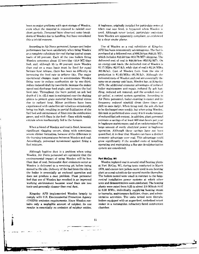
Figure I. Conifer Burner' of type being implemented at Fort McCoy. WI.
c. st of 11.50) Btu/lb (26.7 mJ/kg) coal is $2.09/MBtu equipped with Hoffman mechanical spreader stokers4$1.99/kJl. or less than half the cost of Woodex. and a traveling grate. The unit was rated at 75.000IHowever, the as-manufactured cost of Woodex was lb/hr 134 019 kg/hr), 150 psig (1034 kPal stearn$1.43/MBtu ($1.36/kJ), or about 27 percent of its generating capacity, and was equipped with .'y
delivered cost and 68 percent of the projected cost of mechanical collectors and Hays boiler controls. Thicoal. A reliable supply of Woodex nearer the instal- Woodex tested was produced from bark and ,othcrlation could easily reduce transportation costs and wood products by the process described earlier in t hethereby make Woodex a clear economic competitor discussion of the Kingsley AFB test lp. 101. Wood 'xwith coal for long-term use. pellets measured 0.25 in. (6.4 mini diameter biy 1.50
As an adjunct to the Woodex tests, Fort McCoy is in. 112.7 mm) length, and had an as-fired heating
in the process of modifying a heating plant to fire value of 8100 Btu/Ih 18 836 kJ/kg and a bulk density
locally available green wood chips as a substitute for of 34 lb/cu ft f544 kg/m3).
coal. A Conifer Burner' was recently received and is Experience with passing Woodex through the coalbeing retrofitted to a small boiler serving an auto- handling and storage system was generally satisfactorymotive maintenance facility (Figure 1). When this and no modifications were made to in-place coalunit begins operating, it will provide techno-economic equipment for the test. The fuel was delivered directlydata which the Army will use to determine the relative to the boiler plant in enclosed, bottom-dumping railmerits of using either pelleted wood fuel or chips as a cars and discharged to a receiving pit. From there itheating and power plant fuel substitute for coal. The was taken by vibrating conveyor to the bucket elevator,retrofit is being made at a cost of $3500, and 5000 which carried it to the bunker where it was distributedBtu/lb (11.6 mJ/kg) wood chips are available for by belt conveyor. It was removed from the bunker byapproximately $7.00/ton ($7.69/MT) or $1.43/MBtu a weigh larry and loaded into the boiler frontwalll$1.36/kJ), equivalent to the price the installation feed hopper. A considerable amount of dust wasexpects to pay for coal in the near future. generated during all fuel handling operations, par-
ticularly where there were long drops-in the elevatorRock Island Arsenall, IL pit and bunker area, for example. Representative
Approximately 148 tons (134 MT) of Woodex manu- dust concentrations were measured and analyzed byfactured by Bio-Solar of Brownsville, OR, was tested Arsenal Safety and Industrial Hygiene personnel.as a coal supplement and substitute on 9 and 10 April who determined that concentrations were below those1979.e The tests were run in a Wicks watertube boiler necessary for an explosive atmosphere, but nonetheless
"Personal communication with Mr. 1). Mueller. Facilities En- could present a health hazard. A light water mist
gine.ring Office, Rock Island Arsenal, IL. 26 April 1979. applied to the fuel during handling operations lowered
rn.-- ------------ ---
dust levels without noticeable degradation of the fuel. 118.8 m,J'kgl was purchased at a delivered cost ofFor continued use of Woodex or similar fuels, arsenal $90.(K/ton i$1(K).00/MTI or $5.56i/MBtu $5.28/kJi. Itspersonnel recommend that measures be taken to cost f.o.b. Brownsville, OR. was $28.(0)/ton 1$:31.1 l/MT1reduce dusting from fuel handling equipment, breath- or $1.73/MBtu 1$1.65/k.J. Accordingly Woodex can-ing and eye protection devices be used, and substantial not immediately compete with coal at the Arsenal aaccumulations of (lust not be allowed on floors and locally available supply might be competitive, however.equipment. if the delivered price of coal were to rise to about
$36.40/ton i$40.44/MT1. Of course, this cost comparisonThe Woodex tests at Rock Island Arsenal indicated considers only the fuel and transportation costs and
that the boiler generally performe(d well when firing assumes that the conditions of using Woodex and co4)althe material. The boiler was cold-started and manually are equal. As illustrated in the chapter on economics,brought up to partial capacity on Woodex. Minor this is in fact not the case. Since the future costs ofadjustments were made to change fuel feed trajectory flue gas desulphurization are avoided by using liletedand feed rate. Ulnderfire air was reduced considerably wood in favor of coal, the alternate fuel can befrom that normally used for coal, and overfire air was economically preferable over the long term.maintained to ensure complete combustion. Gratespeed was reduced in order to maintain a sufficientash bed to protect grate materials from furnace radiant Fort Benlamin Harrison, INheat. Throughout the tests, boiler operation was Two tests using Woodex from Tennessee Woodex,maintained on manual control because the automatic Inc., Knoxville, were conducted at Fort Benjamincontrols could not accommodate the low air flows Harrison in March and April 1979. The Woodex usedrequired by Woodex. The tests indicated that over was similar to that tested at Fort McCoy. Approxi-the short term the boiler could be fired with Woodex mately 40 tons 136 MT) were fired during each testat 0.7 to 0.8 capacity, without serious problems, on period. These tests-the most comprehensively in-manual operation, and with achievable operational strumented to date-confirmed experiences elsewhereand control changes. in DOD with pelleted wood fuel, and determined
more precisely than other tests the limitations of theThree USEPA Method 5 particulate emissions tests alternate fuel both as a substitute for and a supplement
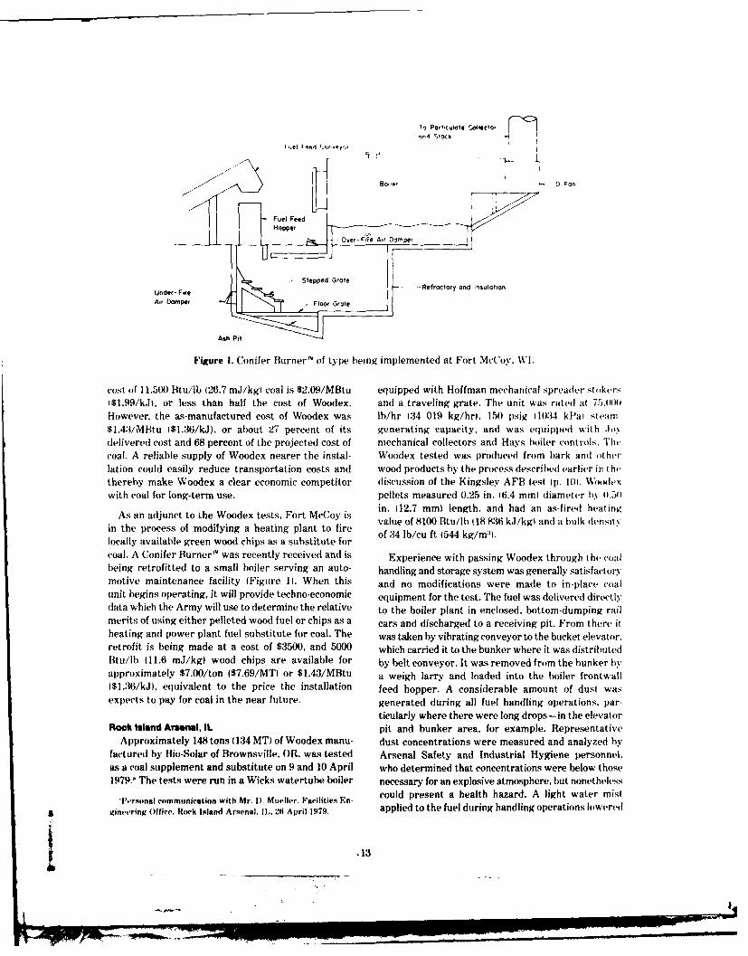
conducted during the Woodex experiment indicated to coal. The first test was conducted as a pretest tothat emissions when firing Woodex were below those determine if any severe problems would occur whenwhen firing Illinois bituminous coal, but still did not using Woodex in a central power system designed forcomply with State of Illinois particulate emissions coal. The success of the pretest paved the way for thelimitations. Allowable particulate emissions for the more intensive second experiment.level of boiler operation at which Woodex was testedare approximately 18 lb/hr (8.2 kg/hr). The three The boiler tested was one of four nearly identicalparticulate emissions tests showed Woodex emissions units in Central Heating Plant No. 1 and is shown into be approximately 44, 31, and 26 lb/hr (20, 14, and Figure 2. It is a 1952 Wickes two-drum, watertube12 kg/hr, respectively), as boiler controls were pro- boiler designed to fire 12,700-Btu (13 396-J), 1.9-percentgressively adjusted to optimize Woodex performance, sulphur, 12-percent ash bituminous coal screened toArsenal personnel observed only very light smoke 15 percent minus 0.25 in. (6.4 mm) from the Centralfrom the stack during the first test, and a clear plume Utility Strip Mine in Montgomery, IN. The design'sfor the ensuing two. Particulate emissions when firing maximum steam-generating capacity is 32,000 lb/hrcoal have been as high as 65 lb/hr (29.5 kg/hr) at (14 515 kg/hr). The waterwall heating surface is 485comparable boiler loads. sq ft (45.1 M 2
) with 3-in. (76.2-mm) side tubes spacedon 7.5-in. (152.4-mm) centers. Boiler heating surface
The Woodex experiments at Rock Island Arsenal is 4713 sq ft (438 m 2) with 2-in. (51-mm) side tubesindicated that pelleted wood fuel may not compete spaced on 5-in. (127-mm) centers. Overall depth is 17economically with coal even if a local supply of the ft (5.2 m) with 11 ft, 8 in. (3.6 m) from front to mudalternate fuel were available. Illinois bituminous coal drum center. Tile-to-tile width is 11 ft (3.4 mi, andwith an as-fired heating value of 10,500 Btu/lb (22 height from floor to steam outlet is 19 ft, 8 in. 16 mi.413 k.J/kg) iN used at the Arsenal with a delivered The upper drum is of the suspended type and measurescost of $29.00/ton ($32.22/MT), or $1.38/MBtu 54 in. (1.4 m) inside diameter (i.d.) by 12 ft., 3.5 in.($1.31/kJ). Woodex with a heating value of 8100 Btu/Ib (3.8 ml long. The mud drum measures 37 in. (0.9 mi
14
14

I_ 17"10'
5'-41/4" 8-958V-
19a FEEDERCONECAO
ARE IT 31/4SW TUBES
Figure 2. Boiler tested at Fort Benjamin Harrison. IN.
id. by about 10 ft (3 m( long. Normal operating system. Combustion air is supplied by a four-ditpressure is 100 psig (690 kPa(, with a maximum of system with 8.625-in. (219-mam) outside diameter !o.dt.lapproximately 160 psig (1103 kPa). Under normal main duct and 6.625-in. (168-mm) duct to undergrate.operating conditions, feedwater temperature is 2250 F The air system includes eighteen 2.50l-in. 164-mml0 070 ( and steam temperature about 35t 0 F (177 0 C1, lines with 1-in. (25.4-mm) overfire nozzles in theThe boiler is equipped with Westinghouse starters, haekwall.Hays-Republic pneumatic controls, dual steam pulse Acieoastrgischvdinni-pntte.
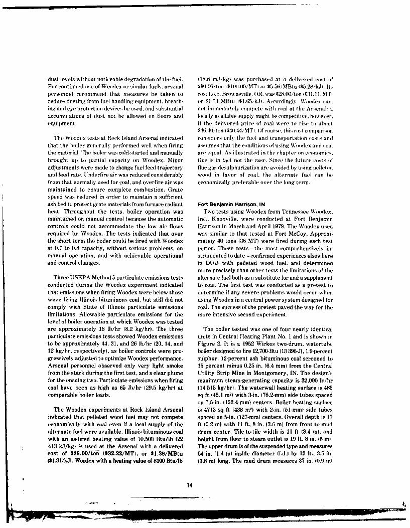
sootlowrs.andbothundrgrte nd oerfre ir. 700-ton (630-MT( capacity, nonpartitioned. parabolicThe unit can be operated either manually or auto- celnbukrsonignracos-ctninF-matically. There is no heat recovery equipment on ceinbukrsonngnra os-etninF-
the luegasend.Fue isfire thoug dua, pralel, ure 3. The bunker is 96 ft (29.3 m) long, 16 ft, 11 in.tfluetas e-n. Fuel- isied thoudal, atralolel, (5.2 ml wide at the top, and 19 ft (5.8 m) deep. It has
fronwal 26in.(0.6-r) Riey ode B ate-coled 16 outlets measuring 2,50 ft by 2.50 ft (0.8 m by 0.8 m)mechanical spreader stoker feeders. The boiler is adsae nieo -t(.-n etr einn
equipe~ wit analloed scilatig grte toke me -: ft (0.9 rn) from each end. Coal typically is not storedsuring 10 ft long by 9 ft wide (3.1 m by 2.7 in) for intebkrmoeha3dysndvrgsaouan effective grate area of 90 sq ft (8.4 in
2). The stokerconsists of two independent, self-cleaning, automatic! 1 day.
manual, heat-resisting alloy grate surfaces supported Fuel is delivered to the plant by truck or front-on reinforced cross-tee grid assemblies. Each is end loader from an outside storage yard nearby, andoperated by separate drive and has front ash discharge dumped through a grade-level grate into a receivingto a plenum served by a manual/pneumatic removal hopper approximately 8 ft (2.4 in) deep. The hopper
..... _ _ _ _ _15
.- ON.- 712 -- ER
TILE AFFI
. 8*- 5 /2" '-5I2
29 26"4 Spaces of 3"0"12;-d' 2#-6"
14!-6"
3'-0
Figure 3. Bunker cross section, Fort Benjamin Harrison, IN.
discharges by gravity through a square outlet mea- equipped with steam ejector serves all four boilers insuring about 1.5 ft by 1.5 ft (0.46 m by 0.46 m) the plant. Temperature, oxygen content, and opacitydirectly to a hinged steel transfer conveyor which of the flue gases are continuously measured down-moves the fuel approximately 20 ft (6.1 m) to the stream from the induced draft fan.bucket elevator which carries it about 50 ft (15.2 mlto the bunker. The fuel is distributed over the length Boiler preparations for the tests were minimal.of the bunker by a manually operated, rail-mounted, Major air leaks were identified and many sealed withdual-discharge distribution system working on an 18-in. duct tape and glazing compound. K-type, chrome-10.5-m) wide rubber belt conveyor with approximately alumel thermocouples were installed in the front andI in. (25.4 mim) unloaded working depth. Fuel is re- rear of each furnace sidewall and in one sidewall nearmoved from the hunker by either of two rail-mounted the screen tube inlet. A USEPA Method 5 air pollutantweigh larries operated manually from the operating emissions test and a plume observation were per-floor of the plant approximately 25 ft (7.6 m) below formed by personnel from the State of Indiana Airthe outlets. From the weigh larries, the fuel is gravity Pollution Control Board.discharged to the boiler frontwall feed hopper, fromwhich it flows by gravity to the mechanical spreaders Table I shows the proximate and ultimate analyseswhich feed it to the furnace. An outdoor ash silo of coal produced at the Central Utility Strip Mine in
16
Montgomery, IN. The coal fired before and after the mined to be between 0.50 and 0.67 of that of the coalWoodex tests was not analyzed. but was assumed to regularly used at the plant. Testing commenced aboutcorrespond reasonably well to the tabulated properties. 5 hours after fuel delivery, and no Woodex remainedHowever, the coal appeared to be higher in fines than in the bunker longer than 36 hours. Some particlespecified and to have accumulated a substantial segregation by size was observed as the pellet/finesquantity of free moisture from melting snow during mixture was distributed into the designated area ofoutside storage. the bunker, and there was a pronounced tendency of
fines to adhere to the hopper walls and not flow freelyTable 2 shows the proximate and ultimate analyses to the outlet. At one point during the test, ratholing
of Woodex typically produced in Knoxville, TN. The threatened continuous Woodex feeding and roddersWoodex appeared to contain substantially less free were needed to restore gravity mass flow. No majormoisture than the coal. Table 3 gives a sieve analysis problems were encountered in running the materialof Woodex samples collected from the boiler frontwall through the weigh larry. Although some spillage offeed hopper. and these data are fairly representative pellets and fines to the operating floor was observed.of the material delivered to the bunker. A unique along with spillage of fines from the two mechanicalcharacteristic of the Woodex was the relatively high feeders on the boiler, these problems might better befraction of fines; however, a final screening stage to described as a housekeeping bother rather than anreduce the fines content of the pelleted Woodex product operating difficulty.was not in operation at the Knoxville Woodex plantwhen the test fuel was manufactured. Further, it Combustion performance of substitute Woodex wasappeared that many pellets broke up as they passed generally satisfactory throughout the short-term test.through the coal-handling system, both at the receiving During the pretest, the boiler was operated on Woodexhopper discharge to the transition conveyor Idue to up to 92 percent maximum capacity rating IM(IRishear stresses on the pelletsi and at the point where with no apparent operational problems. During thethey fell about 17 ft (5.2 m) into the storage bunker. second, more intensive test, the boiler was operated
between 59 percent and 84 percent MCR, with theThe primary problem with Woodex was the large exception of turndown tests where the unit was
amount of dust it produced during delivery and operated below 28 percent MCR. Plant steam demandhandling. Approximately 40 tons (36 MT1 of Woodex during the test was such that a second boiler had towas delivered by truck, discharged directly to the re- be kept on-line, preventing operation of the testedceiving hopper, and conveyed to the designated coal- boiler at greater than 84 percent MCR.free area of the bunker. Considerable dust was gener-ated where the fuel was unloaded from the trucks, Thermal data taken during the test suggested aand throughout the in-plant handling system as well. relative shift in duty between the radiant and convec-Plant personnel observed much dusting and pellet tive sections and a loss of overall fuel-to-product (steamIbreakage where the receiving hopper discharged to efficiency when firing Woodex. At 72 percent M'Rthe steel-hinged transition conveyor. Approximately (normal boiler operating level), furnace gas tempera-50 lb 123 kgl of material spilled from the transition tures when firing Woodex were on the order of 40OFand rubber belt conveyors above the bunker. It was (4*C) higher than when firing coal (1596*F 1869*Clobserved that spillage from the belt conveyor could versus 15550F [8460 C4. Screen tube inlet temperaturebe lessened by resetting the rollers to provide greater averaged 1297*F (703*Cl, or 3.8 percent higher thanworking depth to the belt. High dust density was also with coal. Stack gas temperatures averaged CI9gFobserved in the bunker area during delivery; Table 4 (326*C), or 6 percent greater than with coal, and thegives a sieve analysis of dust collected from surfaces temperature drop across the convective section wasin the bunker area of the plant. approximately 2 percent greater than with coal. The
oxygen content of flue gas varied between 10 and 11Few problems other than minor dusting and spilling percent, and relative air varied between 5.8 and 6.0,
of fines were noticed as the Woodex passed through in contrast to values of 12.7 percent and 5.9 to 6.2.the handling and feeding system at the Fort Benjamin respectively, when firing coal. It was observed thatHarrison plant. The fuel was stored in one end of the flue gas oxygen content could have been reduced hadbunker in a pile measuring approximately 20 ft long the system been equipped with finer controls forby 11 ft wide by 10 ft high (61 m by 3.4 m by 3.1 m) underfire and overfire air. Since a boiler efficiencyand covering three outlets. Fuel density was deter- test was not conducted, no data are available on the
L ,,_in 17
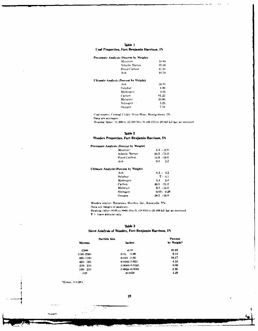
TBble ICoal Properties, Fort Benjamin Harrison, IN
Proximate Analysis (Percent hil Weighto
Moisture IO.)
Volatile Matter 37.30iFixed ('arbon 41.20Ash 10.70
Ultimate Analysis (Percent by Weight)Ash 10.70Sulphur 4.90Hydrogen 4.35('arbon 61.52Moist ure 10.80Nitrogen 1.25Oxygen 7.18
Coal source: 'entral U tility Strip Mine. Montgomery. IN.lata are averages.
Heating Value: 1.:1(I to 12.500) Htiu 1) 126 27:1 to 29 416:1 kJ/kgi as received.
Tsble 2Woodex Properties, Fort Benjamin Harrison, IN
Proximate Analysis (Percent by Weight)Moisture 4.3 -12.0Volatile Matter 50.0 -71.0
Fixed Carbon 14.0 -19.0Ash 0.3 - 3.2
Ultimate Analysis (Percent by Weight)Ash 0.3 - :3.2Sulphur T- 0.1
Hydrogen 5.4 - 5.8Carbon 46.5 -51.2Moisture 9.3 - 16.0
Nitrogen 0.03- 0.26Oxygen 38.5 - :19.8
Woodex source: Tennessee Woodex, Inc.. Knoxville. TN.
Data are ranges of analyses.Heating value: SlN) to S8)5) lit u/il) 1 IS833 to 20 4M) kJ,'kgl as-received.T = trace amount only.
Table 3
Sieve Analysis of Woodex, Fort Benjamin Harrison, IN
Particle Size PercentMicrons Inches by Welght*
,23l10 09 60.931190-23810 0.5 -0.(4 9.13595-I f9) 0.023 -0-0t5 10.17
420- 595 0.)165-0.023 4.56
21)0- 210) O.1E8:-0).O165 8.09
149- 210 ().0059-).0):l 2.35,149 olIw59 4.29
S*Ern r: + 1).484
18
-. .: ... .
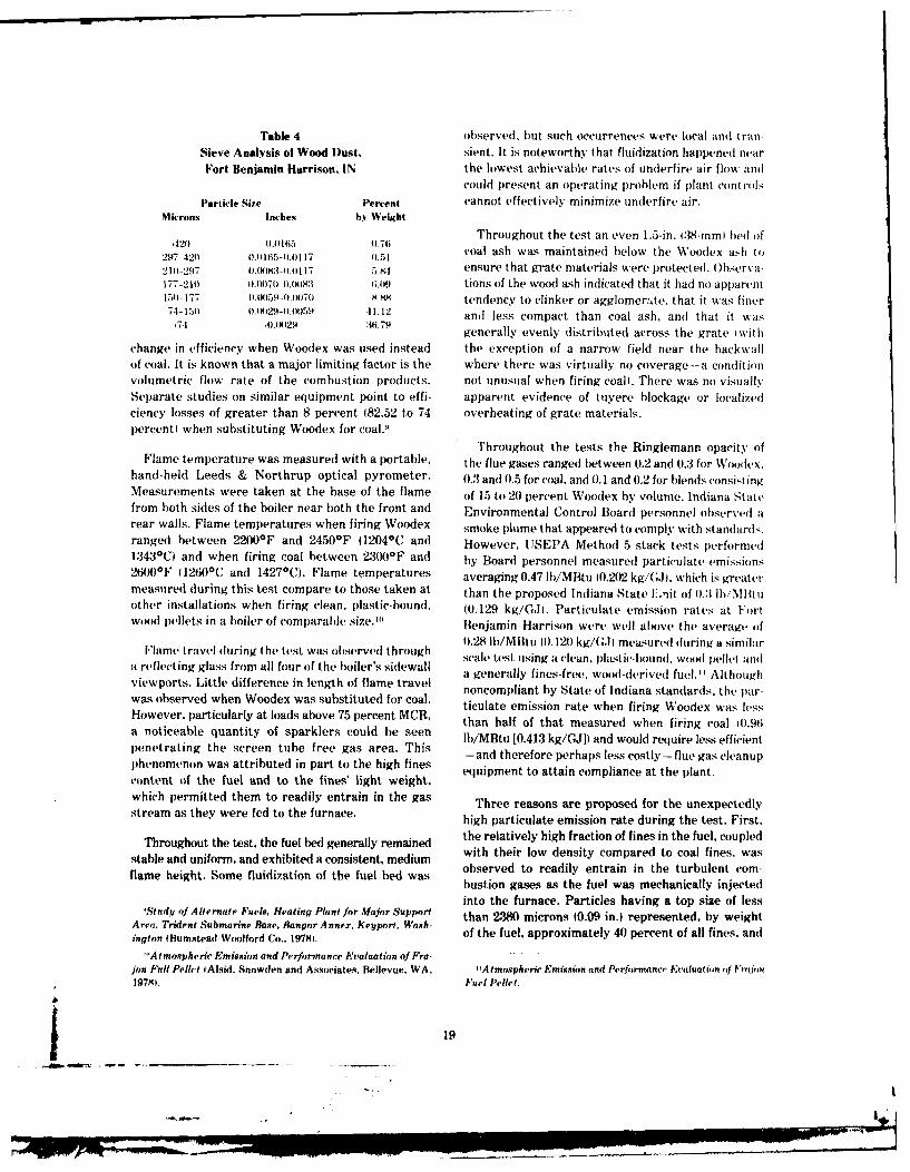
Table 4 observed, but such occurrences were local and tranSieve Analysis of Wood )ust. sient. It is noteworthy that fluidization happened nearFort Benjamin Harrison, IN the lowest achievable rates of underfire air flow and
could present an operating problem if plant controlsParticle Size Percent cannot effectively minimize underfire air.
Microns Inches by Weight
Throughout the test an even 1.5-in. i38-mm bed of*29-420 Of)I.01 17 0.51coal ash was maintained below the Woodex ash to
2,") -42 I)I)16 -0.0 IT0.51
210-297 ,.IX:;-O.O 117 5.84 ensure that grate materials were protected. ()bserva-177-210 ).(N)70-0.01H)83 (;.9 tions of the wood ash indicated that it had no apparent151-177 0.0059-0.007o 8.8 tendency to clinker or agglomerate, that it was finer74-151 ).)29-).)5.1 11.12 and less compact than coal ash, and that it was
71)29 :16.79generally evenly distributed across the grate with
change in efficiency when Woodex was used instead the exception of a narrow field near the backwallof coal. It is known that a major limiting factor is the where there was virtually no coverage-a conditionvolumetric flow rate of the combustion products. not unusual when firing coal). There was no visuallySeparate studies on similar equipment point to effi- apparent evidence of tuyere blockage or localizedciency losses of greater than 8 percent (82.52 to 74 overheating of grate materials.percent) when substituting Woodex for coalY
Throughout the tests the Ringlemann opacity ofFlame temperature was measured with a portable, the flue gases ranged between 0.2 and 0.3 for Wsex.
hand-held Leeds & Northrup optical pyrometer. 0.3 and 0.5 for coal. and 0.1 and 0.2 for blends consistingMeasurements were taken at the base of the flame of 15 to 20 percent Woodex by volume. Indiana Statfrom both sides of the boiler near both the front and Environmental Control Board personnel observed arear walls. Flame temperatures when firing Woodex smoke plume that appeared to comply with standards.ranged between 2'200*F and 2450*F (12040C and However, USEPA Method 5 stack tests performed1343C) and when firing coal between 2300OF and by Board personnel measured particulate emissions26(H)*F (1260 0 C and 1427aC). Flame temperatures averaging 0.47 Ib/MBtu (0.202 kg/G.t, which is greatermeasured (luring this test compare to those taken at than the proposed Indiana State liit of 0.3 lb'Mlituother installations when firing clean, plastic-bound, (0.129 kg/G.Jl. Particulate emission rates at Fortwood pellets in a boiler of comparable size.'" Benjamin Harrison were well above the average of
0.28 Ib/MBtu (0.120 kg/G.li measured during a similarIFlam, i ravelI ,luring t he tI st was ,)l lstrvt1d through scale, te st using a ('lean. iilastit'- 11,)unnd, woo~d pelletl and
a reflecting glass from all four of the boiler's sidew all a e st. in es-frea , wo o - d ood pel lthand
viewports. Little difference in length of flame travel nonomliy tae o Indina standA thughwas bsevedwhe Wooex as ubsitutd fr cal. noncompliant by State of Indiana standards. the par-was observed when Woodex was substituted for coal. ticulate emission rate when firing Woodex was less
However, particularly at loads above 75 percent MCR, than half of that measured when firing coal 10.96
a noticeable quantity of sparklers could be seen tb/MBtu [0.413 kg/G]) and would require less efficient
penetrating the screen tube free gas area. This [-and therefore perhaps less costly-flue gas cleanup
phenomenon was attributed in part to the high fines -a n t o att a ps l e t the p lant.
content of the fuel and to the fines' light weight, equipment to attain compliance at the plant.
which permitted them to readily entrain in the gas Three reasons are proposed for the unexpectedlystream as they were fed to the furnace, high particulate emission rate during the test. First,
the relatively high fraction of fines in the fuel, coupledThroughout the test, the fuel bed generally remained wt hi o est oprdt olfns a
stable and uniform, and exhibited a consistent, medium with their low density compared to coal fines, was
flame height. Some fluidization of the fuel bed was bstio ea the fe was mehncly cte-bustion gases as the fuel was mechanically injected
into the furnace. Particles having a top size of less'Study of Alternate Fuels. Heating Plant for Major Support than 2380 microns (0.09 in.) represented, by weight
Area. Trident Submarine Base, Bangor Annex, Keyport, Wash- of the fuel, approximately 40 percent of all fines, andington (Bumstead-Woolford Co.. 1978).
"Atmospheric Emission and Performance Evaluation of Fro- . ..jon Full Pellet IAlsid. Snowden and Associates. Bellevue. WA, 'Atmospheric Emission and Performance Evaluation, (q Vjj1979), Fuel Pellet.
__ __ I_ _1

1.0
0.9
PI: 2 -IN BED DEPTHCO 0.8-
IN Pi=0.12- 1.6H +470H2
C5 0.7- R2 0.940.7
w 0.6- I-I
0.5-ww!a 0.4-
4 tP 2 4-IN BED DEPTH"j 0.' P? = 0.508 + 2.28H - 1.54 H2
0.1R2=0.92
. 0 ,
0.30 0.35 0.40 0.45 0.50 0.55 0.60
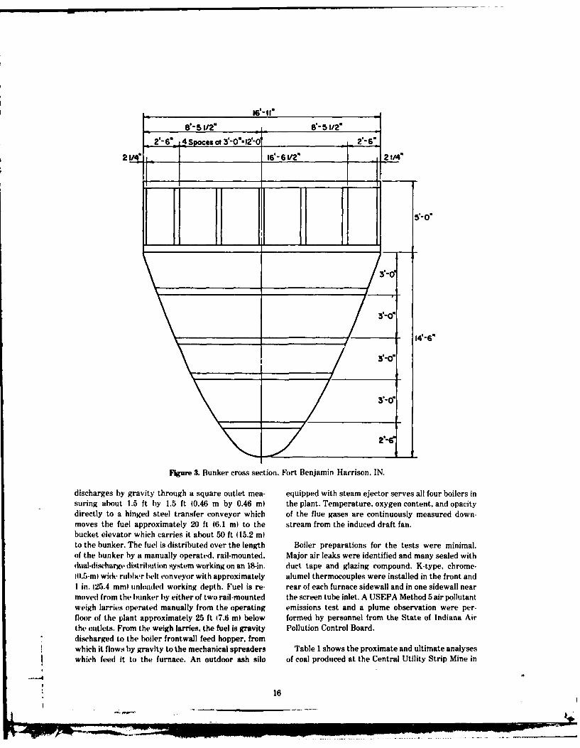
H, HEAT RELEASE RATE (MBtu/hr- ft 2 GRATE AREA)Figure 4. Relation of fuel bed depth to particulate emissions from wood-fired boilers.
a significant portion of these particles remained in when relatively light ash, such as generated from thesuspension andl were carried by the gas stream to the combustion of Woodex, passes into them. Third, whenscreen tubes. In the typical operation of a spreader- wood is fired, fuel bed thickness (depth) has beenstoker firing a fuel for which it is designed, between shown to control particulate carryover (Figure 4).'M0 and 50 percent of the combustion takes place in Increasing the depth of the fuel bed can reduce thesuspension and the remainder on the fuel bed.' 2 As- rate of fly-ash carryover, and there is even more re-suming :i0 percent of the balance of the Woodex burned duction as the fuel-feed rate is increased. As Figure 4in suspension, the total mass fraction of fuel combusted shows, for a normal operating range of 0.45 to 0.55above the fuel bed can be conservatively estimated at MBtu/hr-sq ft (5.11 to 6.25 GJ/hr-m2( grate heat58 percent. Hence, there was a distinct shift in the release rate, a fuel bed 4 in. (102 min deep couldrelative roles of bed and suspension burning; the have resulted in emission rates compliant with thelatter increased and probably resulted in greater fly-ash prsed in State omliant (0.129carryover. Second, little fly ash from the Woodex was proposed Indiana State level of 0.3 Ib/MBtu )0.129removed from the flue gases by the mechanical col- kg/GJ). During the Woodex test, however, feeder-lectors, which were designed for coal ash. Such collec- turnup rate was the limiting factor because it was nottors work on the principle of inertial separation of possible to increase the fuel-mass flow rate to theparticulate from the carrier gas, and their efficiency furnace beyond the point where a fuel bed aboutis directly related to particle density; the heavier the 1.5 in. (38.1 mm) deep would accumulate. It wasparticles, the greater the efficiency. Hence, the col- observed that larger capacity feeders operating on alectors' mass fractional removal efficiency will be less fuel significantly lower in fines could have achieved
'-Stokers for Industrial Boilers-Assessment of Technical, I 1K. luttle and D. Junge. "Combustion Mechanisms in W(dEconomic, and Environmental Factors, PB288689 (Battelle- Mired Boilers," Journal of the Air Pollution ControlAsseciation.Columbus Laboratories, 1975). Vol 28. No. 7 July 1978).
20
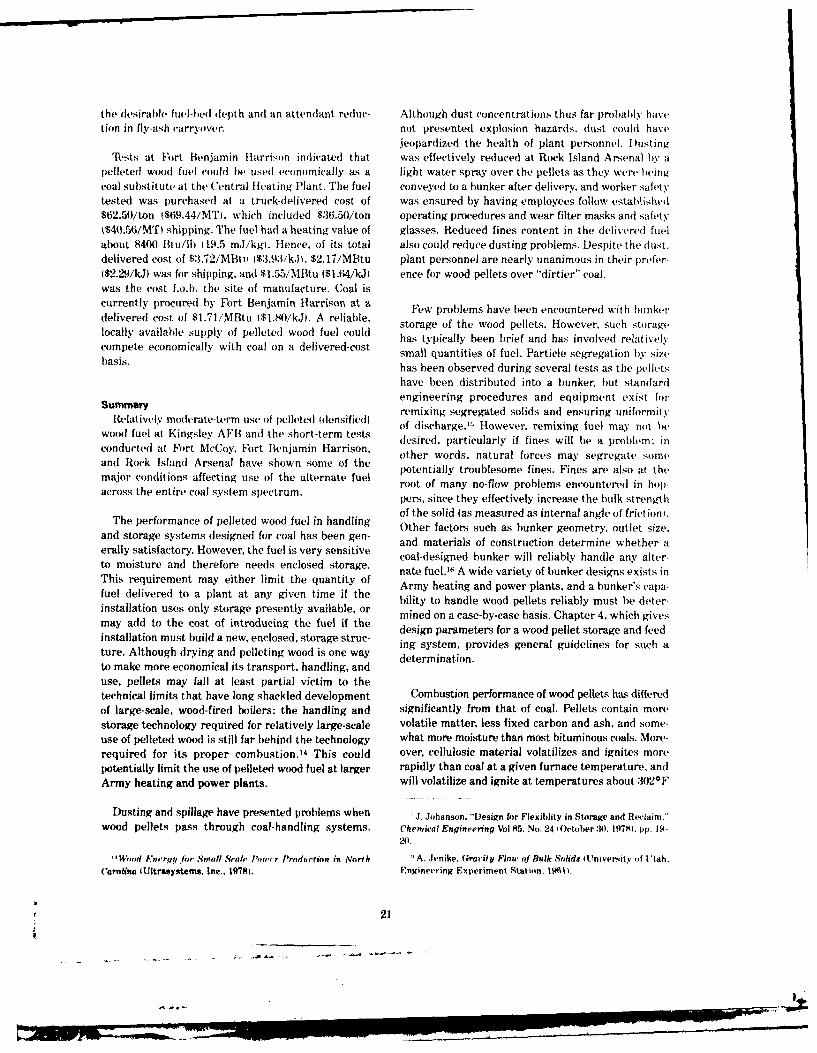
the desirable fuel-bed depth and an attendant reduc- Although dust concentrations thus far probably havetion in fly-ash carryover, not presented explosion hazards, dust could have
jeopardized the health of plant personnel. IDustingTt'sts at Fort Benjamin Harrison indicated that was effectively reduced at Rock Island Arsenal b y a
pelleted wood fuel could be used economically as a light water spray over the pellets as they were beingcoal substitute at the Central Heating Plant. The fuel conveyed to a bunker after delivery, and worker safetytested was purchased at a truck-delivered cost of was ensured by having employees follow established$62.50/ton ($t9.44/MT), which included $36.50/ton operating procedures and wear filter masks and safetyI$40.56/MT) shipping. The fuel had a heating value of glasses. Reduced fines content in the delivered fuelabout 8400 Btu/lb 119.5 m.J/kg). Hence, of its total also could reduce dusting problems. Despite the dust.delivered cost of $3.72/Mti 1$3.93/k.), $2.17/MBtu plant personnel are nearly unanimous in their prefer-($2.29/kJ) was for shipping, and $1.55/MBtu l$1.64/kJ) ence for wood pellets over "dirtier" coal.was the cost f.o.b. the site of manufacture. Coal iscurrently procured by Fort Benjamin Harrison at a Few problems have been encountered with bunkerdelivered cost of $1.71/MBtu 1$1.80/kJ. A reliable, storage of the wood pellets. However, such storagelocally available supply of pelleted wood fuel could has typically been brief and has involved relativelycompete economically with coal on a delivered-cost small quantities of fuel. Particle segregation by sizebasis. has been observed during several tests as the pellets
have been distributed into a bunker, but standard
Summary engineering procedures and equipment exist forremixing segregated solids and ensuring uniformity
Relatiely moderate-tArm use of pelleted tdensified of discharge.': However. remixing fuel may not bewood fuel at Kingsley AFBI andi the short-term tests desired, particularly if fines will be a problem: in
conducted at Fort McCoy, Fort Benjamin Harrison, other words, natural forces may segregate some
and Rock Island Arsenal have shown some of the potentially troublesome fines. Fines are also at the
major conditions affecting use of the alternate fuel roteofiay o- ble s enere in hacros te enirecoalsysem sectum.root of many no-flow problems encountered in hop-
across the entire coal system spectrum. pers, since they effectively increase the bulk strengthof the solid (as measured as internal angle of friction).
The performance of pelleted wood fuel in handling Other factors such as bunker geometry, outlet size,and storage systems hesigned for coal has been gen and materials of construction determine whether aeraly satisfactory. However, the fuel is very sensitive coal-designed bunker will reliably handle any alter-to moisture and therefore needs enclosed storage. nate fuel."6 A wide variety of bunker designs exists inThis requirement may either limit the quantity of Army heating and power plants, and a bunker's capa-fuel delivered to a plant at any given time if the bility to handle wood pellets reliably must be deter-installation uses only storage presently available, or mined on a case-by-case basis. Chapter 4. which gives
may add to the cost of introducing the fuel if the dn aaeers a od per an fe
installation must build a new, enclosed, storage struc- ing system, provides general guidelines for such a
ture. Although drying and pelleting wood is one way determination.
to make more economical its transport, handling, and
use, pellets may fall at least partial victim to thetechnical limits that have long shackled development Combustion performance of wood pellets has differedof large-scale, wood-fired boilers: the handling and significantly from that of coal. Pellets contain morestorage technology required for relatively large-scale volatile matter, less fixed carbon and ash, and some-use of pelleted wood is still far behind the technology what more moisture than most bituminous coals. More-required for its proper combustion.14 This could over, cellulosic material volatilizes and ignites morepotentially limit the use of pelleted wood fuel at larger rapidly than coal at a given furnace temperature, andArmy heating and power plants. will volatilize and ignite at temperatures about 302*F
Dusting and spillage have presented problems when ' ,J..Jhhanson. "Design for Flexiblity in Storage and Rclaim"wood pellets pass through coal-handling systems. Chemical Engineering Vol N5. No. 24 1October 30, 19781. pp. 19-
20.
Wod Energy for Small Scale Pou-cr I'roduction in North " A. Jenike, Grarity Flow of Bulk Solids University of t 'tah.Carolina Uitrasystems. Inc., 19781. Engineering Experiment Station. 1.11.
21
-1
W
1150*0 less than Midwest Bituminous Coal.I- Accord- encountered when firing coal. Hence, if control tml,ingly, when wood pellet-coal blends are fired, the ment must be added when firing wood pellets. it ma*.pellets can tend to quench coal combustion, resulting be a less efficient and lower cost device than highin clinkering and excessive smoke. Operating adjust- efficiency, high-cost systems such as baghouse .ments to accommodate firing substitute pellets haveincluded increasing the fuel feed rate and modulatingoverfire and underfire air, In many cases, the desira- Econoical ot apearsetha wood pelltspcanicodble low level of underfire air flow has not been achiev- pete with coal on a delivered cost basis providedable because the boilers tested lacked the fine controls there is a supply of pellets nearby. Coal costs rang(for such modulation. In other cases, it has not been from $1.3/MBtu to $2.18iMBtu /kJ to $2.Ae i kwbpossible to achieve adequate overfire velocity and at the test locations mentioned above. Pelleted wcta ldistribution to provide sufficient turbulence, and hence fuel has been purchased at a delivered cost rangingresienc tie, or te wod uel(paricuarl fies) from $2.17/MBtu to $5.56/MBtu 152.07/ki to $5.28 ,k.h'residence time, for the wood fuel particularlylocations. However the cost of wood pelletto combust completely in the radiant furnace cham- f.o.b. site of manufacture has had a relatively smallher. Nevertheless, wood pellets have been used rang, bte f manufatu and a re at rely smalsucessull asa cal ubsitte t bile lods angng range, between $1.43iMBtu and $1.73/M~tu t$l.:*irklsuccessfully as a coal substitute at boiler loads ranging and $1.65/kJ). While delivered costs of wood pelletsfrom 0.28 to 0.85. A major limiting factor has beentheare essentially above the range of coal costs, their
larger for wood pellets than for coal. Moreover, pellet as-produced costs lie well within those of coal. Hence.
firing in a boiler designed for coal is accompanied by under current regulations governing transport of
a shift in relative duty between the radiant and con- pelleted wood fuel, transportation distance is a major
vective heat exchange sections and a probable drop factor in limiting its price competitiveness with coal.
in boiler fuel-to-product conversion efficiency.
Since firing wood pellets appears to generate both DENSIFIED BIOMASSless ash and finer ash than coal, the depth of ash bed 3 PRODUCTIONneeded to protect grate materials from iradiantsthermal stress is of some concern. Special alloys mayneed to be used as grate material when switchingfrom coal to pellets. Plant personnel where wood Geeralpellets have been tested believe wood ash is more Sevea rent nsera bio m rou toneasiy hndld b pnumaic sstes tan oalash processes are now in operation throughout the world.easily handled by pneumatic systems than coal ash Their common features include the capacity to removeand leads to reduced wear both of pneumatic lines moisture from virgin or as-harvested raw matrialand of internal boiler surfaces. Since the ash is acre- and to create an appropriate form of fuel that can bedynamically light, though, it readily entrains in com- handled, stored, and burned in a system designee -bustion gases and is difficult to remove with control another fuel. In the case of wood, the as-harvesteddevices working on the principle of inertial separation moisture content can be as high as 50 percent byfrom carrier gas. weight; reducing this will not only improve its effec-
tiveness as a fuel, but also will make its transportWhether wood pellets will meet air pollutant emis- more economical since the weight of "unproductive"
sions limitations everywhere is presently speculative, masses of water will not be moved with the fuel. FuelEmissions of sulphur oxides and nitrogen oxides should form is dictated by the needs of the system in whichnot be a problem since the fuel contains negligible the material is a possible substitute or supplementalsulphur, and flame temperatures are relatively low, fuel. In some applications, dry pulverized biomassParticulate emissions across all tests have ranged can be used effectively in its loose or unconsolidat,dfrom compliant to noncompliant, but unanimously form using state-of-art burner technology retrofittedhave been on the order of half of what usually is to a boiler.", For use in most installation-scale central
heating and power plants equipped with mechanical"Reactivity and Gasification Characteristics of Lou, Ranking stokers to fire coal, the fuel must be pelleted to
('oats and Potentially Reducing Waste Materials (Pittsburgh resemble coal in general form.Energy Research Center, 1976): S. A. Hathaway and J. Lin,Th'rmogratvimtric Analysis of Solid Refuse-Derived Fuels and -
Coal. Technical Report E-149/ADA067829 ICERL, March 1979). ISolid Furl Burners (Peabody Gordon-Platt. Inc.. 1979).
22- 5

DELIVERED HOGGED WOODFED BY FRONT ENDDUMP STACK LOADER
TO ATMOSPHEREAUXILIARYFEED HOPPER
FUET SCREW CONVEYOR
DE TO ATMOSPHERE600°F I--- = URCEIPUMP OUTLET GAS 0; BOE
8OO° | CYCLONE SEPARATOR
MLHAMMER- TO ATMOSPHERE
SOME FEEDSTOCK SEPARATOR FABRIC FILTERTO FUEL FURNACE
FOR DRYER -- DUST REINJECTION
o I LIVE BOTTOM SURGE BIN
FINES PELLETIZERCTIO- CONTROLS
SCREEN
DBDF TO SCALE ANDSTORAGE OR USER
Figure 5. Wood pellet production process
23
Production Process The feedstock is conveyed pneumatically from theA typical wood pellet production process is illus- dryer through a cyclone separator to the shredder. A
trated in Figure 5.1' Important unit operations are typical shredder is a horizontal shaft hammermilldrying, shredding, pelleting, and screening. While with between 250 and 350 connected horsepower 1186
pelleting and screening are always the final unit oper- and 26I kWel. Additional moisture is lost in theations, some piants shred first then dry, while others shredding operation, along with small amounts ofdry then shre(,. The sequence depends on the nature dust, From the shredder, feedstock is conveyed to aof the delivered material, which normally is hogged live-bottom surge bin where it is held on a first-in.or chipped wood from a mobile operation working first-out basis. A pneumatic conveying system ('an heforested land. If the material has a high moisture used, in which case a cyclone separator must becontent, initial drying prevents useless mass from installed, along with a fabric filter to remove fineentering the shredder. Conversely, dryer efficiency dust from cyclone outlet air before it is released tois partly related to material particle size and is apt the atmosphere. Traditional belt conveyors can alsoto be somewhat improved when the equipment is be used, but caution must be exercised in their designoperating on shredded material rather than coarse or selection to prevent excessive dusting and spillinggrade input, of the feedstock.
Pellets with an as-fired heating value ranging be- The surge bin functions as a load leveler for down-
tween 80(X) and 9000 Btu/Ib (18 603 to 20 929 mJ/kg) stream equipment and as temporary storage of par-
and having a moisture content on the order of 12 tially processed feedstock. A typical surge bin is the
percent by weight are produced from such a process. live bottom drag conveyor type, which feeds material
An average Army boiler producing 40,000 lb/hr to a plenum along its front wall. A constant pitch and
18 144 kg/hri steam would thus require between 80 flight screw conveyor in the plenum feeds the mate-
and 90 tons/day 172 and 81 MT/day) wood pellets as rial to the pelletizer inlet hopper. A fraction of the
fuel. For a typical 3-day active fuel storage time, feedstock is taken (usually pneumatically) from the
approximately 250 tons (225 MT) must be stockpiled. surge bin and used to supply the furnace for the
The requirement for larger plants will increase pro- dryer. Fines collected from a downstream pellet
portionately. Few Army heating or power plants screening operation and dust collected in the fabric
exceed 200 MBtuh (59 MWt) total input capacity, filter can be reclaimed and cycled to the surge bin to
equivalent to a daily wood pellet requirement of join the feedstock.
about 300 tons (270 MT?. Several types of pelletizers are commercially avail-
able; these include mechanical extrusion mills, cubet-
Equipment and Functions ters, roller-compressors, and screw extruder. Many
A typical wood pellet production plant includes companies opt for mechanical extrusion devices withreplaceable dies. Capacities ranging from I to 5
conveors, feeders, a dryer, a furnace to provide heat tons/hour (0.9 to 4.5 MT/hr) are available. The millfor the dryer, a shredder, a surge bin, a pelleter, a typically requires from 250 to 350 connected horse-
screen, cyclone separators, and a fabric filter. Equip- pwer f186 to 261 konnd actualment can be housed in a pre-engineered building onkWe). Experimentation and actualpoed cncrte sl in ms le-enimae. Seilg fon operation have indicated that pelletizers operate bestpoured concrete slab in most climates. Special foun- on a feedstock containing between 10 percent anddations are usually required for heavier process equip- 18 percent moisture by weight and at temperaturesment. ranging from 210OF to 260*F i99*C to 127 0 C. Water
A typical plant contains a receiving area to accept in the feedstock acts as a heat sink to prevent the
deliveries of raw material (hogged or chipped wood), pellets from being scorched in the densification process.
which is moved by a front-end loader or conveyer (if a A small steam vent is necessary. and sometimes dust
live bottom receiving hopper is selected) to the dryer collection equipment is required.
(or shredder if this is placed first). Heat for the dryer Binders such as pitch and, more recently, environ-is supplied by a furnace firing a fraction of the fuel mentally clean scrap plastic have been used to improvetaken from either a downstream separator or the the handling characteristics of wood pellets.21 Binderssurge bin.
-"'Atmospheric Emission and P'erfarvnanc.- Evaluati,,n ,t*( Fa'Personal communication with Mr. Duane Schaub, Guaranty jon Fuel PIllet (Alid, Snowden and Associat.s. Rc.lhv.ue. WA.
Performance Co., Independence. KS. 22 March 1979. 1978L
24
are addted to the wood pellet feedstock through a The .ntrg. anl., ,s if in 1(t iiti pro(Iito ionti I
metering fhedltr tin the densificatin mill. ('ombusti ,atd an otvrall ,.ffi,.,,.,V. ,f K.5..i in i,. a I..h ,
bith hinders may enhance the com bu tstion perform somewhat h , than .t ,,i . n, ri hc he ' the .m I
ance of the pellet hut could also place limitations on Energ' tesearch In-titlvt. iSEl{, in a ,imilar analvsistorage equipment and residence time, particularly of a :;l ton daN 17i MT dayi hark pellet plant.2 l
because of the possibility of "leakage" and migration SERI reported a proess energy efficiency of 92.8of the binding agent. percent for a hypothetical plant consisting of six
hammermills. two pelletizers, and a dryer coupledAfter the pelletizer, the wood pellets are mechan- with a wood gasifier, to produce pellets having a
ically conveyed to a screen to remove fines, which are moisture content of I0 percent by weight and a heat-returned to the surge bin. Numerous screening devices ing value of 8(tX(I Htu; lh 18 6(13 m.J/kg. Neither theare commercially available, ranging from simple SERI analysis nor this investigation considered theshakers to more complex air scalpers. Care must be energy cost of harvesting, transporting and chippingexercised in screen selection, since the hot pellets the raw material delivered to the pellet productioncoming from the pelletizer remain rather fragile until plant. Such a determination was outside the scopes ofthey cool. This is partly because lignins in the feedstock both studies.are liberated under heat and must cool before theycan function effectively as a natural pellet binder. The efficiency f the wood pellet production processPellets normally are weighed before being sent either is somewhat nn.;eading, since "efficiency" is not used
to storage or to the user. here in a conventional sense. The efficiencies of 85.3
A typical wood pellet production line includes (on- percent determined in this investigation and 92.s
troils which can le operated both in automatic and percent determined by SERI are merely a second
manual modes. Normally, all operations are visible way of presenting the fact that the energy added to
from the central control console. Safety interlock the delivered material (listed as Energy Input inTable 51 is partially recovered in the product pellet.
systems are recommended, along with lockable master po exmlteeegeurdfrdyn pperswitches near all major equipment. Fire extinguishers. For example, the energy required for drying appearsswithesnea al majr euipent F~r exingishrs. as an input. The larger fraction of this input is the
a master sprinkler system, and remote alarms are en input. eaporate watr. Appoximaterecommended. energy required to evaporate water. Apprximately
66 percent of the enegy using for drying is recapturedin the pellets' increased heat of combustion. It is
Energy Analysis important to note also that although drying is a major
Energy analyses of wood pelleting operations indi- energy user, it greatly increases combustion equip-
cate that pelleted wood fuel can be produced for ment capacity, improves heat transfer in a boiler, and
about 181 kWh/ton 1716 mJ/MT) input material or reduces emissions of air pollutants.22
:28 kWh/ton 11298 mJ/MT) output. Table 5 givesaverage energy balance data for a wood pellet pro-duction operation. The data are based on a 3-shift/day Product Characteristicsoperation receiving 120 tons/day (108 MT/day) of The production and use of wood pellets can behogged hark and wood having a moisture content of viewed in the context of a classical fuel substitution50 percent by weight. The operation is assumed to problem. At an installation where wood is availableproduce 66 tons/day (59 MT/day) wood pellets having as an energy resource, the military manager must
a moisture content of 10 percent by weight and a choose the most effective way to use it. The alterna-heating value of 8350 Btu/Ib (19 417 kJ/kg). The data tives typically confronting him are: (I) constructingshown are averages indicative of general operation new equipment (usually a plant) to store, handle andand the relative magnitude of energy consumption by fire relatively unprocessed material (chips or hogged
major individual unit operations. wood), or (2) investing in wood processing equipmentto produce a fuel usable in an existing plant. In a
Primary energy consumers are the hammermill.
pelletizer, and dryer. Ibtal connected power can range '. Reed and B. Bryant. Lkiisifted Riomass: A Ncv form fbetween 1000 and 1400 HP (743 and 1044 kMe). At Solid Fuel. SERI-35 iSolar Energy Research Institute. 19781.approximately ,300 HP (224 kWet each, the hammermill :-R. Arola, Wood F'itcts-Hom Do Thcy Stms-k 'p? *Energyand pelletizer together account for about 50 percent and the Wood Products industry. Forest Products Researchof the connected power requirement. Society. Madison, WI. 19761.
_25

Table 5Energy Analysis of 120 Thns/Day (108 MT/DayI
Wood Pellet Operation
TotalConnected EnergyElectrical Consumed
(kW) MBtu/dav IGJ/day)Energy Input
Front '.nd Loader N.A. 9.04 9.5,Dryer
Feedstowk as Fuel N.A. 75.4 179.)Auxiliary Fuel N.A. 4.5 4,71Drives 97.7 MM0 8.41
flammermill 224.1 191.4 119.41I'elletizer 224.6 18.4 19.41Motors
i nc'. h,,wters. Pneurmatcl 2:8.1 19.5 120.61General
ilnel. Lighting (ontr,ls.Safety System 119.6 9.8 11.3 1
Tot a] 904.6 162.6 t 171.6)
Energy Output
Wood Pellets166 tons. 8:150 Btu 1t). ]t' !I 01 NA. 1102.2, 1162.9)159.86( MT. 19.05 +,I kg, I f,III),
EfficiencyIH,× 11102.2 W1.2
/ . 2 ; ) M)5.: s
*Not applicable.
growing number (if cases, %%ood pellets are becoming which will perform properly in systems designed foravailable to installations, and this presents yet a third coal. Moisture content and form are important fuelalternative. The decision to produce or procure wood variables which directly influence fuel performancepellets is based on economics, which, in turn, depends in boilers.upon what costs are associated with ensuring thepellets' reliable, proper performance in a heating or The moisture content of raw wood is variable andpower system designed for another fuel, such as coal. significant in terms of the material's fuel potential.23The classical fuel substitution approach requires that It usually varies between 20 and 55 percent by weight,the extent t, which a virgin energy resource must be and can be as high as 67 percent on an as-receivedprocessed for effective use he determined by the basis. Moisture content also varies with species. treecharacteristics of the particular heating or power age, and tree material. Hardwoods contain an averagtsystem chosen for conversion. Such an approach is of 30.2 percent by weight moisture, while softwoodsnearly always taken when converting gas- or oil-fired contain an average of 46.1 percent. Young trees containplants to coal, but ;uch has not been entirely the case more moisture than those which have passed theirwith wood pellets, where experience to date has growth rate peak. Foliage (leaves, needles, andfocused on ihort-term testing of a product which branches) contains more moisture than the bole. and.recently entered the market as a widely advertised within the bole, sapwood contains more water thancoal substitute. the heartwood. Conversely, nearly all coals contain
The objectives of the wood pellet production pro-cesses now in operation are to reduce the moisture :'D. Tiliman, Wood as an Enerqy Resourre (Academic Press.content of virgin wood and to convert it into a form 197S),
26
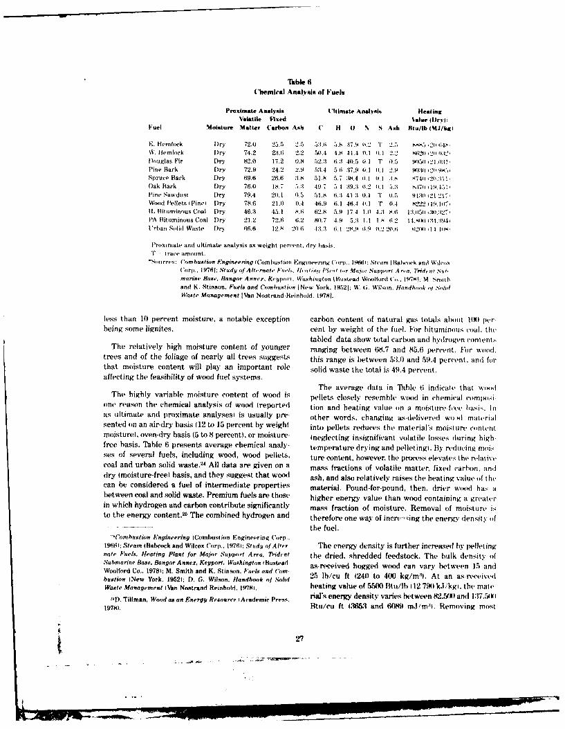
Tble 6('hemical Analysis of Fuels
Proximate Analysis .'litlmate Analysis HeatingVolatile Fixed %alue h )r* :
Fuel Moisture Matter Carbon Ash C H o N S Ash Btu/Ib (MJ/kgi
E. Hemlock Dry 72.0 25.5 2.5 5:.6 3 .8 :,7.4 W4.2 T 2.7, sM5,2H 64?,W. Hemlock Dry 74.2 23.6 2.2 51.4 4.8 41-4 1). 11.1 2.2 86211 r203:4,Douglas Fir Dry 82.0 17.2 0.8 52.3 6.3 40.5 0.1 T 41.5 L150 '21 0:1,Pine Bark Dry 72.9 24.2 2.9 53.4 5.6 :37.9 4.1 0.1 2.9 90:012119K iSpruce Bark Dry 69.6 26.6 3.8 51.8 5.7 :3,4.4 0.1 0.1 :1.s K740 t 20. 1 ,Oak Bark Dry 76.0 18.7 5.3 49.7 7.1 3 49.3 4.2 44.1 5.: .7,) .I 4. I"I
,
Pine Sawdust Dry 79.4 20.1 0.5 51.8, 6.3 41.1 O. T 0.5 91:V 124 21-7,Wood Pellets (Pinel Dry 78.6 21.4 0.4 46.9 6.1 46.1 0. 1 T 4.4 8=22119.117,I1 Bituminous Coal Dry 46.3 45.1 8.6 62.8 5.9 17.4 1.0 4.A 8.6 1:3,115n,:44:427PA Bituminous Coal 1)ry 21.2 72.6 6.2 80.7 4.9 5.3 4.1 1.8 6.2 14.45 :1,:194,Urban Solid Waste Dry 46.6 12.8 244 #; 13.3 6.1 28.9 14.9 44.2 204.6 W204,11 lo44
Proximate and ultimate analysis as weight percent. dry basis.T - (race, amount.
"S,urcts; 'ornhustion Engineering (Combustion EngineerinK Corp.. 4fil: Stci'm I Ba cowk and WilctxCorp.. 19761; Study of A,rnate o, F,/1. I i 04 I'lt ' r Majoi .'upport .4 ri.a. 71idcnt Submarine Base. Bangor Annex. Keport. Wishinylon I Bustead Willord Coi.. 1.47M1; M Smithand K. Stinson, Fuels and Combustion I New York, 19521: W. ;. Wilson. ltandh, k , 0hdWaste Management [Van Nostrand-Reinhold, 19781.
less than 10 percent moisture, a notable exception carbon content of natural gas totals about 1(A) perbeing some lignites. cent by weight of the fuel. For bituminous coal, the
tabled data show total carbon and hydrogen contentsThe relatively high moisture content of younger ranging between 68.7 and 85.6 percent. For wood,
trees and of the foliage of nearly all trees suggest, this range is between 53.0 and 59.4 percent. and forthat moisture content will play an important role solid waste the total is 49.4 percent.affecting the feasibility of wood fuel systems.
The average data in Table 6 indicate that woodThe highly variable moisture content of wood is pellets closely resemble wool in chemical c'(mitesi
one reason the chemical analysis of wood (reported tion and heating value (in a moisture-free hasi. Inas ultimate and proximate analyses is usually pre- other words, changing as-delivered wo I materialsented on an air-dry basis (12 to 15 percent by weight into pellets reduces the material's moist tire c(ontentmoisture), oven-dry basis (5 to 8 percent), or moisture- Ineglecting insignificant volatile losses during high-free basis. Table 6 presents average chemical analy- temperature drying and pelletingi. By reducing moises of several fuels, including wood, wood pellets. ture content, however, the process elevates the relativecoal and urban solid waste.2' All data are given on a mass fractions of volatile matter, fixed tarbon. an(]dry (moisture-free) basis, and they suggest that wood ash, and also relatively raises the heating value of thecan be considered a fuel of intermediate properties material. Pound-for-pound, then, drier wood has abetween coal and solid waste. Premium fuels are those higher energy value than wood containing a greaterin which hydrogen and carbon contribute significantly mass fraction of moisture. Removal of moisture isto the energy content.25 The combined hydrogen and therefore one way of incre ing the energy density of
the fuel."Combustion Engineering (Combustion Engineering Corp..
1966); Steam (Babcock and Wilcox Corp., 19761: Study of Alter The energy density is further increaseed by pelletingnate Fuels. Heating Plant for Major Support Area, Trident the dried, shredded feedstock. The bulk density ofSubmarine Base, Bangor Annex, Keyport, Washington (Bustead as-received hogged wood can vary between 15 andWoolford Co.. 1978); M. Smith and K. Stinson. Fuels and ('om-bus io Ne Yrk.195);D. . Wlsn. andoo (I Soid 25 lb/cu ft (240 to 400 kg/n 1). At an as-receivedbastion I New York, 1952); D. G. Wilson. Handbook of .4olidWaste Management (Van Nostrand-Reinhold, 19781. heating value of 5500 Btu/ib 112 790 kl/kg. the matt'
D. Tillman, Wood as an Energy Resource tAcademic Press. rial's energy density varies between 82,50) and 17,,UkI1978). Btu/cu ft (3653 and 61189 m.Imli. Removing most
27
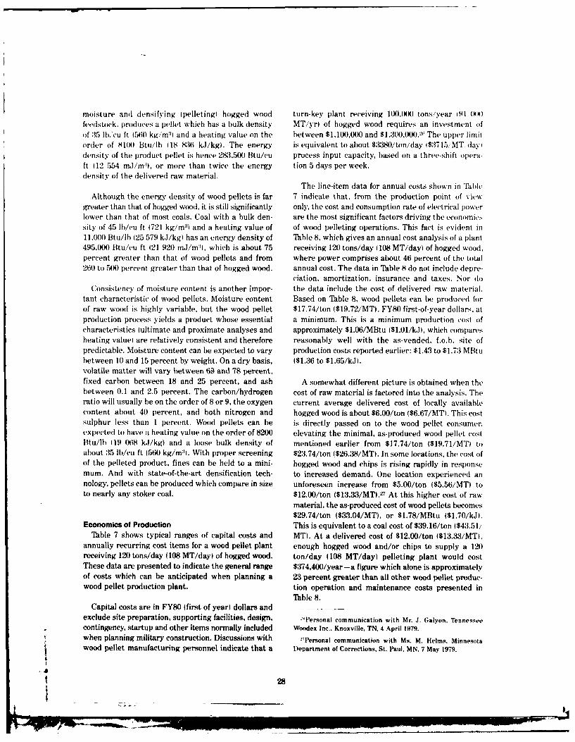
moisture and densifying 1pelleting) hogged wood turn-key plant receiving 1(X))0 tons/year 191 (WK)feedstock. produces a pellet which has a bulk density MT/yr) of hogged wood requires an investment oifof :15 lb,'cu ft 1560 kg/m: and a heating value on the between $1,100,000 and $1.30,(X)0.2i The upper limitorder of 8100 Btu/lb (18 8:36 k.J/kg). The energy is equivalent to about $380/ton/day 1$3715,MT day,density of the product pellet is hence 283,500 Btu/cu process input capacity, based on a three-shift opera-It 12 554 mJ/m'), or more than twice the energy tion 5 days per week.density of the delivered raw material.
The line-item data for annual costs shown in PaleAlthough the energy density of wood pellets is far 7 indicate that, from the production point of view
greater than that of hogged wood, it is still significantly only, the cost and consumption rate of electrical poiwerlower than that of most coals. Coal with a bulk den- are the most significant factors driving the economicssity of 45 lb/cu ft 1721 kg/m :') and a heating value of of wood pelleting operations. This fact is evident in11,000 Btu/Ib (25 579 kJ/kg) has an energy density of Table 8, which gives an annual cost analysis of a plant495,000 Btu/cu ft 121 920 mJ/m"), which is about 75 receiving 120 tons/day d108 MT/day) of hogged wood.percent greater than that of wood pellets and from where power comprises about 46 percent of the total260 to 500 percent greater than that of hogged wood. annual cost. The data in Table 8 do not include depre-
ciation, amortization, insurance and taxes. Nor doConsistency of moisture content is another impor- the data include the cost of delivered raw material.
tant characteristic of wood pellets. Moisture content Based on Table 8, wood pellets can be produced forof raw wood is highly variable, but the wood pellet $17.74/ton ($19.72/MT, FY80 first-of-year dollars. atproduction process yields a product whose essential a minimum. This is a minimum production cost ofcharacteristics lultimate and proximate analyses and approximately $1.06/MBtu ($1.01/kJ), which comparesheating value) are relatively consistent and therefore reasonably well with the as-vended, f.o.b. site ofpredictable. Moisture content can be expected to vary production costs reported earlier: $1.43 to $1.73 MBtubetween 10 and 15 percent by weight. On a dry basis, ($1.36 to $1.65/kJ).volatile matter will vary between 64 and 78 percent,fixed carbon between 18 and 25 percent, and ash A somewhat different picture is obtained when thebetween 0.1 and 2.5 percent. The carbon/hydrogen cost of raw material is factored into the analysis. Theratio will usually be on the order of 8 or 9, the oxygen current average delivered cost of locally availablecontent about 40 percent, and both nitrogen and hogged wood is about $6.00/ton ($6.67/MT). This costsulphur less than 1 percent. Wood pellets can be is directly passed on to the wood pellet consumer,expected to have a heating value on the order of 8200 elevating the minimal, as-produced wood pellet costBtu/lb 119 068 k.J/kg) and a loose bulk density of mentioned earlier from $17.74/ton 1$19.71/MT) toabout :15 Ib/cu ft (560 kg/m:) With proper screening $23.74/ton ($26.38/MT). In some locations, the cost ofof the pelleted product, fines can be held to a mini- hogged wood and chips is rising rapidly in responsemum. And with state-of-the-art densification tech- to increased demand. One location experienced annology, pellets can be produced which compare in size unforeseen increase from $5.00/ton ($5.56/MT) toto nearly any stoker coal. $12.00/ton ($13.33/MT).2 7 At this higher cost of raw
material, the as-produced cost of wood pellets becomes$29.74/ton ($33.04/MT), or $1.78/MBtu ($1.70/kJ).
Economics of Production This is equivalent to a coal cost of $39.16/ton ($43.51/Table 7 shows typical ranges of capital costs and MT). At a delivered cost of $12.00/ton ($13.33/MT),
annually recurring cost items for a wood pellet plant enough hogged wood and/or chips to supply a 120receiving 120 tons/day (108 MT/day) of hogged wood. ton/day (108 MT/day) pelleting plant would costThese data are presented to indicate the general range $374,400/year-a figure which alone is approximatelyof costs which can be anticipated when planning a 23 percent greater than all other wood pellet produc-wood pellet production plant. tion operation and maintenance costs presented in
Table 8.Capital costs are in FY80 (first of year) dollars and
exclude site preparation, supporting facilities, design, -"Personal communication with Mr. J. Galyon, Tennesseecontingency, startup and other items normally included Woodex Inc.. Knoxville, TN. 4 April 1979.when planning military construction. Discussions with -Personal communication with Ms. M. Helms, Minnesotawood pellet manufacturing personnel indicate that a Department of Corrections, St. Paul, MN, 7 May 1979.
28
p
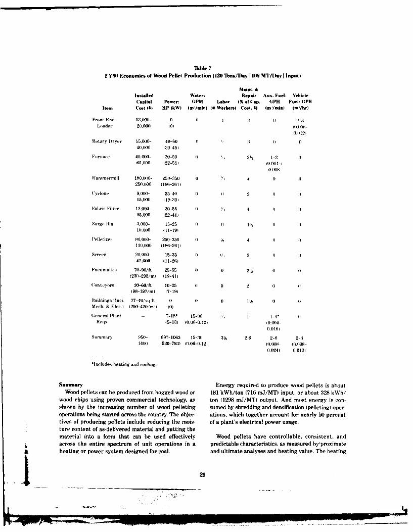
Table 7FY8) Economics of Wood Pellet Production (120 Tons/Day 1108 MT/Day I Input)
Maint. &Installed Water: Repair Aux. Fuel: NehicleCapital Power: GPM Labor (% of Cap. GPH Fuel: GPH
Item Cost 1I HP lkW) (m/mini (# Workers) Cost. $I (m'/mini (m/hr)
Front End 13,000- 0 0 1 3 0 2-3Loader 20.000 0) 10.(X)-
0.0121
Rotary Dryer 15.0O- 40-6) ) :4 : 1 040,000 (30-45
Furnace 40.H)0- :30-50 0 2' 1-2 06500 22-D 0.004-1
0.(X)8
Hfammermill 180,04)0- 250-350 0 '/ 4 0 0250,000 186-2611
(yclne 9,000- 25-40 0 0 2 015,000 (19-:301
Fabric Filter 12.000- :30-55 1) V, 4 )95.00() (22-41)
Surge Bin 3,000- 15-25 (0 0 11 () 0
10,(X) t11-191
Pelletizer 80.0))- 250-350 0 b 4 0 0I 10.() (186-261)
Screen 20.(0)- 15-35 ) 3 0 042.0(K) 111-261
Pneumatics 70-90/ft 25-55 0 o 2'/2 ()(230-295/m (19-411
unveyors 30-60/ft 10-25 0) 0 2 0 (198-197/m) (7-19)
Buildings I nci. 27-4)/sq ft 0 0 0 1 0 0Mech. & Elec.) (290-420/m-'1 (0)
General Plant - 7-18" 15-30 /, 1 1-4" 0Reqs (5-13 (0.06-(1.12) 10014-
0.0161
Summary 95)- 697-1063 15-30 31 z 2.6 2-6 2-314() (520-793) t).06-0.121 (0.)8- (.0(8-
0.024) 0.0121
•Includes heating and cooling.
Summary Energy required to produce wood pellets is aboutWood pellets can be produced from hogged wood or 181 kWh/ton (716 mJ/MT) input, or about 328 kWh/
wood chips using proven commercial technology, as ton (1298 mJ/MTi output. And most energy is con-shown by the increasing number of wood pelleting sumed by shredding and densification (pelletingi oper-operations being started across the country. The objec- ations, which together account for nearly 50 percenttives of producing pellets include reducing the mois- of a plant's electrical power usage.ture content of as-delivered material and putting thematerial into a form that can be used effectively Wood pellets have controllable, consistent, andacross the entire spectrum of unit operations in a predictable characteristics, as measured by 'proximateheating or power system designed for coal. and ultimate analyses and heating value, The heating
_29
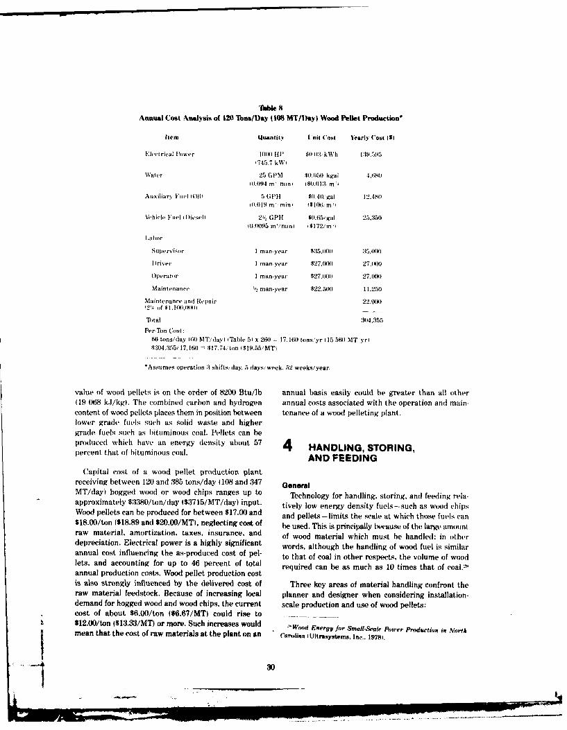
"lhble 8
Annual Cost Analysis of 120 Tons/Day J 108 MT/Day) Wood Pellet Production'
Item Quantity tnit Cost Yearly Cost gid
Elect rhal fl'ower I)M1) 111 $0.13 kWh 139,595(745.7 kW i
Water 25 (PM $0.050 kgal .1,6511
10.094 mI minp 1$0.0),'3 m I
Auxiliary Fuel 1(ili 5 GPI $0.40/gal 12.4800.019 m' mini 1$106/ mI
Vehicle Fuel i iDiesel i 21/ GPH $0.65/gal 25.350
0.01)95 m/min) i$172/mi
labor
Supervisor I man-year $:35,001) 35,)0
Driver I man-year $27.00 27.000
Operator I man-year $27.000 27,11)41
Maintenance 'A, man-year $22.514) 11,250
Maintenance and Repair 22.00012'/, of $1.100M)XI
TM)tal 304,355
Per-Ton Cost:66 tons/day 160 MT/dayl M Table 5I x 260 = 17,160 tons/yr 115 560 MT yri
$304.355/17.160 = $17.74/ton t$19.55/MTi
'Assumes operation :3 shifts/ day. 5 days/week, 52 weeks/year.
value of wood pellets is on the order of 8200 Btu/lb annual basis easily could be greater than all other(19 068 kJ/kg). The combined carbon and hydrogen annual costs associated with the operation and main-content of wood pellets places them in position between tenance of a wood pelleting plant.lower grade fuels such as solid waste and highergrade fuels such as bituminous coal. Pellets can beproduced which have an energy density about 57 4 HANDLING, STORING,percent that of bituminous coal. AND FEEDING
Capital cost of a wood pellet production plantreceiving between 120 and 385 tons/day (108 and 347 GeneralMT/day) hogged wood or wood chips ranges up to Technology for handling, storing, and feeding rela-approximately $3380/ton/day ($3715/MT/day) input. tively low energy density fuels-such as wood chipsWood pellets can be produced for between $17.00 and and pellets-limits the scale at which those fuels can$18.00/ton ($18.89 and $20.00/MT), neglecting cost of be used. This is principally because of the large amountraw material, amortization, taxes, insurance, and of wood material which must be handled; in otherdepreciation. Electrical power is a highly significant words, although the handling of wood fuel is similarannual cost influencing the as-produced cost of pel- to that of coal in other respects, the volume of woodlets, and accounting for up to 46 percent of total required can be as much as 10 times that of coal.L8annual production costs,. Wood pellet production costis also strongly influenced by the delivered cost of Three key areas of material handling confront theraw material feedstock. Because of increasing local planner and designer when considering installation-demand for hogged wood and wood chips, the current scale production and use of wood pellets:cost of about $6.00/ton ($6.67/MT) could rise to$12.00/ton ($13.33/MT) or more. Such increases would Wood Energy for Small-Scaie Power Production in North
mean that the cost of raw materials at the plant on an Carolina 1 UItrasystems. Inc-, 19781.
!_ _
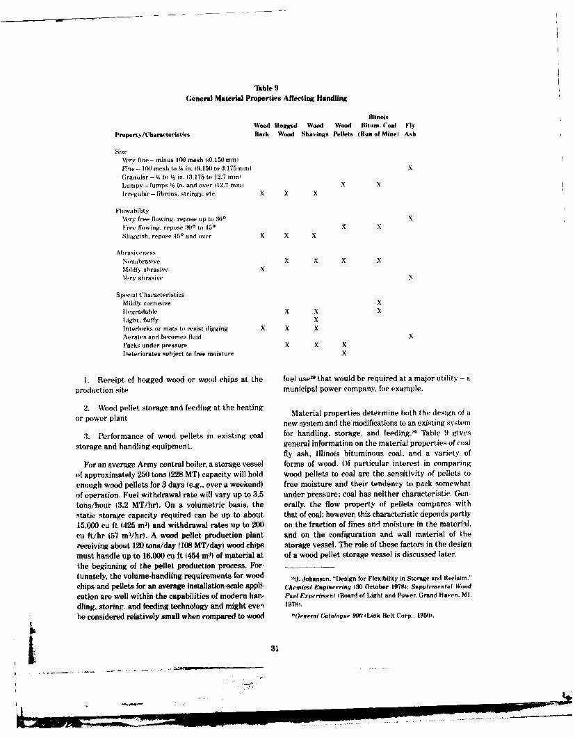
Iable 9General Material Properties Affecting Handling
IllinoisWood Hogged Wood Wood Bitun. Coal FI3
Property/Characteristics Bark Wood Shavings Pellets (Run of Mine) Ash
Size
Very fine-minus 100 mesh (0.150mmIFlne- 100 mesh to V@ in. (0.150 to 3.175 mini XGranular-1/ to in. 13.175 to 12.7 miniLumpy -- lumps 16 in. and over 12.7 minI X X
Irregular-fibrous, stringy. etc. X X X
FlowabilityVery free flowing, repose up to :100 XFree flowing, repose 300 to 450 X XSluggish. repose 450 and over X X X
AbrasivenessNonabrasive X X X XMildly abrasive XVery abrasive
Special CharacteristicsMildly corrosive XDegradable X X XLight, fluffy X
Interlocks or mats to resist digging X X XAerales and becomes fluidPacks under pressure X X X
Deteriorates subject to free moisture X
1. Receipt of hogged wood or wood chips at the fuel use24 that would be required at a major utility - a
production site municipal power company, for example.
2. Wood pellet storage and feeding at the heating Material properties determine both the design of aor power plant new system and the modifications to an existing system
3. Performance of wood pellets in existing coal for handling, storage, and feeding. :"' Table 9 gives
storage and handling equipment. general information on the material properties of coalfly ash, Illinois bituminous coal, and a variety of
For an average Army central boiler, a storage vessel forms of wood. Of particular interest in comparingof approximately 250 tons (228 MT) capacity will hold wood pellets to coal are the sensitivity of pellets to
enough wood pellets for 3 days (e.g., over a weekend) free moisture and their tendency to pack somewhatof operation. Fuel withdrawal rate will vary up to 3.5 under pressure; coal has neither characteristic. Gen-tons/hour (3.2 MT/hr). On a volumetric basis, the erally, the flow property of pellets compares with
static storage capacity required can be up to about that of coal; however, this characteristic depends partly15,000 cu ft (425 M3) and withdrawal rates up to 200 on the fraction of fines and moisture in the material,cu ft/hr (57 m3/hr). A wood pellet production plant and on the configuration and wall material of the
receiving about 120 tons/day (108 MT/day) wood chips storage vessel. The role of these factors in the designmust handle up to 16,000 cu ft 1454 m) of material at of a wood pellet storage vessel is discussed later.the beginning of the pellet production process. For-tunately, the volume-handling requirements for wood ,J. Johanson. "Design for Flexibility in Storage and Reclaim."
chips and pellets for an average installation-scale appli- Chemical Engineering (30 October 19781; Supplemental Wood
cation are well within the capabilities of modern han- Fuel Fxperiment lBoard of Light and Power. Grand Haven. MI.
dling, storing, and feeding technology and might even 19781.
be considered relatively small when compared to wood "'General Catalogue 900 1 Link Belt Corp.. 1950i.
ow31
-...
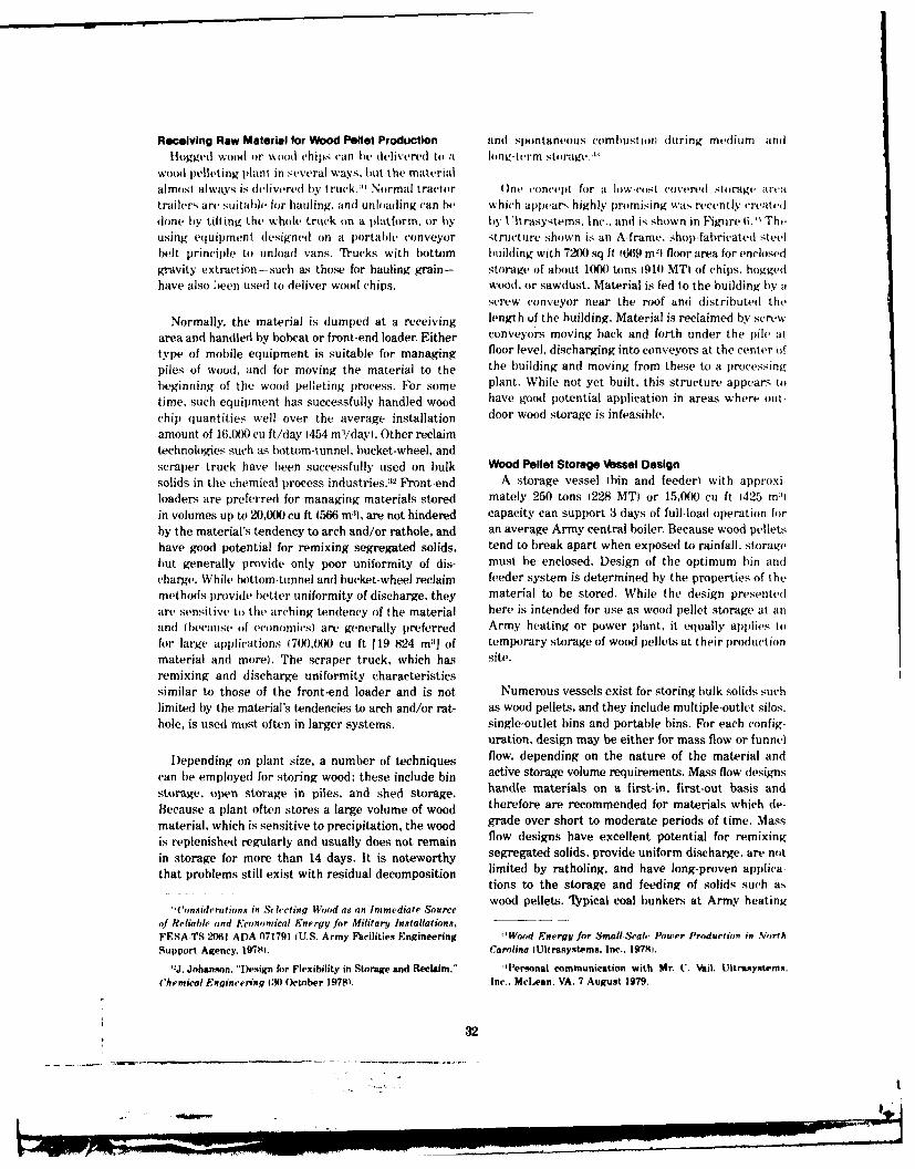
Receiving Raw Material for Wood Pellet Production and spontaneous combustion during medium andHiogged wood or wood chips can be delivered to a honv-trm storage.
Wood i)elleting plant in several ways, but the materialalmost always is delivered by truck.1 Normal tractor ()ne co ncept for a low-cost covered storage art atrailers are suitable for hauling, and unloading can be which appears highly promising was recently createddone by tilting the whole truck on a platform, or by by Vitrasystems. Inc.. and is shown in Figure 6. ' Theusing equipment designed on a portable conveyor structure shown is an A-frame, shop-fabricatedi steelbelt principle to unload vans. Trucks with bottom building with 7200 sq ft 1669 m
21 floor area for enclosed
gravity extraction-such as those for hauling grain- storage of about I(N) tons 1910 MTI of chips, hoggedhave also bieen used to deliver wood chips. wood. or sawdust. Material is fed to the building by a
screw conveyor near the roof and distributed the
Normally, the material is (jumped at a receiving length of the building. Material is reclaimed by screw
area and handled by bobcat or front-end loader. Either conveyors moving back and forth under the pile at
type of mobile equipment is suitable for managing floor level, discharging into conveyors at the center of
piles of wood, and for moving the material to the the building and moving from these to a processing
beginning of the wood pelleting process. For some plant. While not yet built, this structure appears to
time, such equipment has successfully handled wood have good potential application in areas where out-
chip quantities well over the average installation door wood storage is infeasible.
amount of 16,000 cu ft/day (454 m:/dayl. Other reclaimtechnologies such as bottom-tunnel, bucket-wheel, andscraper truck have been successfully used on bulk Wood Pellet Storage Vessel Designsolids in the chemical process industries.:2 Front-end A storage vessel tbin and feeder) with approxi-loaders are preferred for managing materials stored mately 250 tons (228 MT) or 15,0)0 cu ft 1425 milin volumes up to 20,000 cu ft (566 M3), are not hindered capacity can support 3 days of full-load operation forby the material's tendency to arch and/or rathole, and an average Army central boiler. Because wood pelletshave good potential for remixing segregated solids, tend to break apart when exposed to rainfall, storagebut generally provide only poor uniformity of dis- must be enclosed. Design of the optimum bin andcharge. While bottom-tunnel and bucket-wheel reclaim feeder system is determined by the properties of themethods provide better uniformity of discharge, they material to be stored. While the design presentedare sensitive to the arching tendency of the material here is intended for use as wood pellet storage at anand ibecause of economics) are generally preferred Army heating or power plant, it equally applies tofor large applications (7(X),)00 cu ft 119 824 m:1 of temporary storage of wood pellets at their productionmaterial and more). The scraper truck, which has site.
remixing and discharge uniformity characteristicssimilar to those of the front-end loader and is not Numerous vessels exist for storing hulk solids suchlimited by the material's tendencies to arch and/or rat- as wood pellets, and they include multiple-outlet silos.hole, is used most often in larger systems. single-outlet bins and portable bins. For each config-
uration, design may be either for mass flow or funnel
Depending on plant size, a number of techniques flow, depending on the nature of the material and
can be employed for storing wood; these include bin active storage volume requirements. Mass flow designs
storage, open storage in piles, and shed storage. handle materials on a first-in, first-out basis and
Because a plant often stores a large volume of wood therefore are recommended for materials which de-
material, which is sensitive to precipitation, the wood grade over short to moderate periods of time. Mass
is replenished regularly and usually does not remain flow designs have excellent potential for remixing
in storage for more than 14 days. It is noteworthy segregated solids, provide uniform discharge, are not
that problems still exist with residual decomposition limited by ratholing, and have long-proven applications to the storage and feeding of solids such aswood pellets. t ypical coal bunkers at Army heating
'('onsiderations in Selecting Wood as an Immediate Source
of Reliable and Economical Energy for Military Installations,FESA-TS-2061 ADA 071791 (U.S. Army Facilities Engineering Wood Energy for Small-Seal, Power Production in Ntrth
Support Agency. 197$. Carolina lUltrasystems. Inc.. 19781.
J. Johanson. "Design for Flexibility in Storage and Reclaim," Personal communication with Mr. 1U. Vail, Uitrasystems.Chemical Engineering 130 October 1978t. Inc., McLean. VA. 7 August 1979.
32
,°a
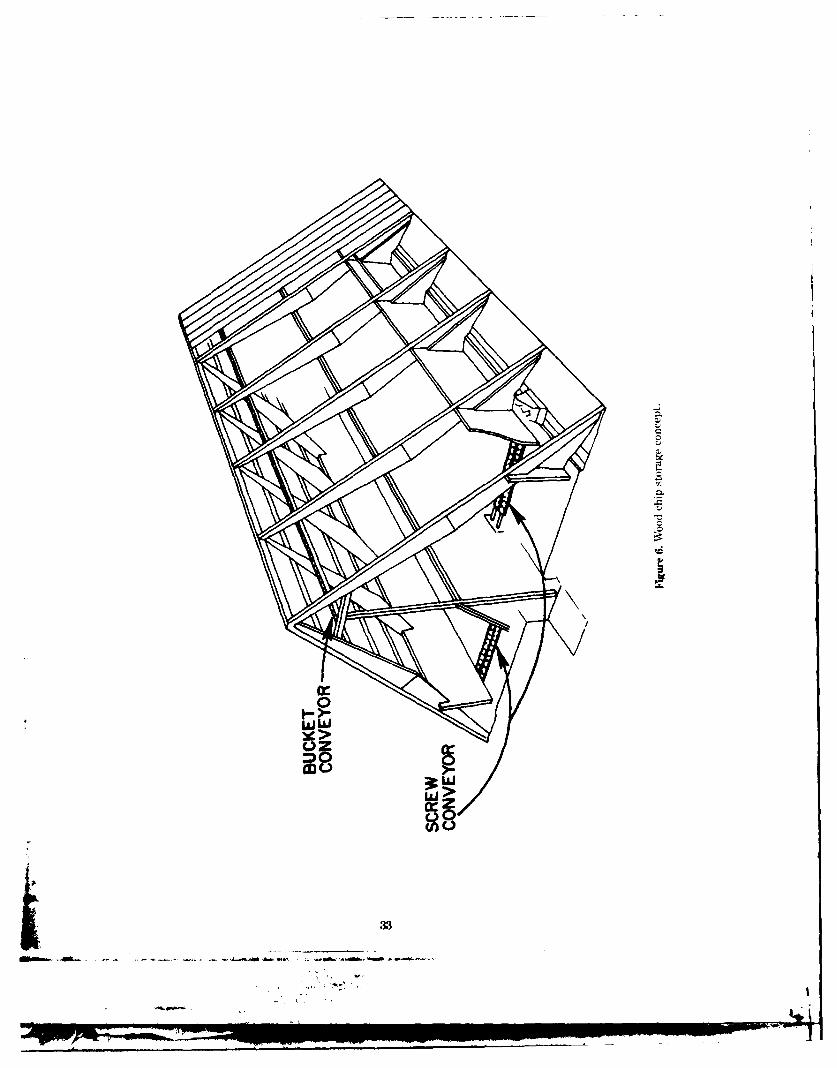
060
UJW>
1 _ 33
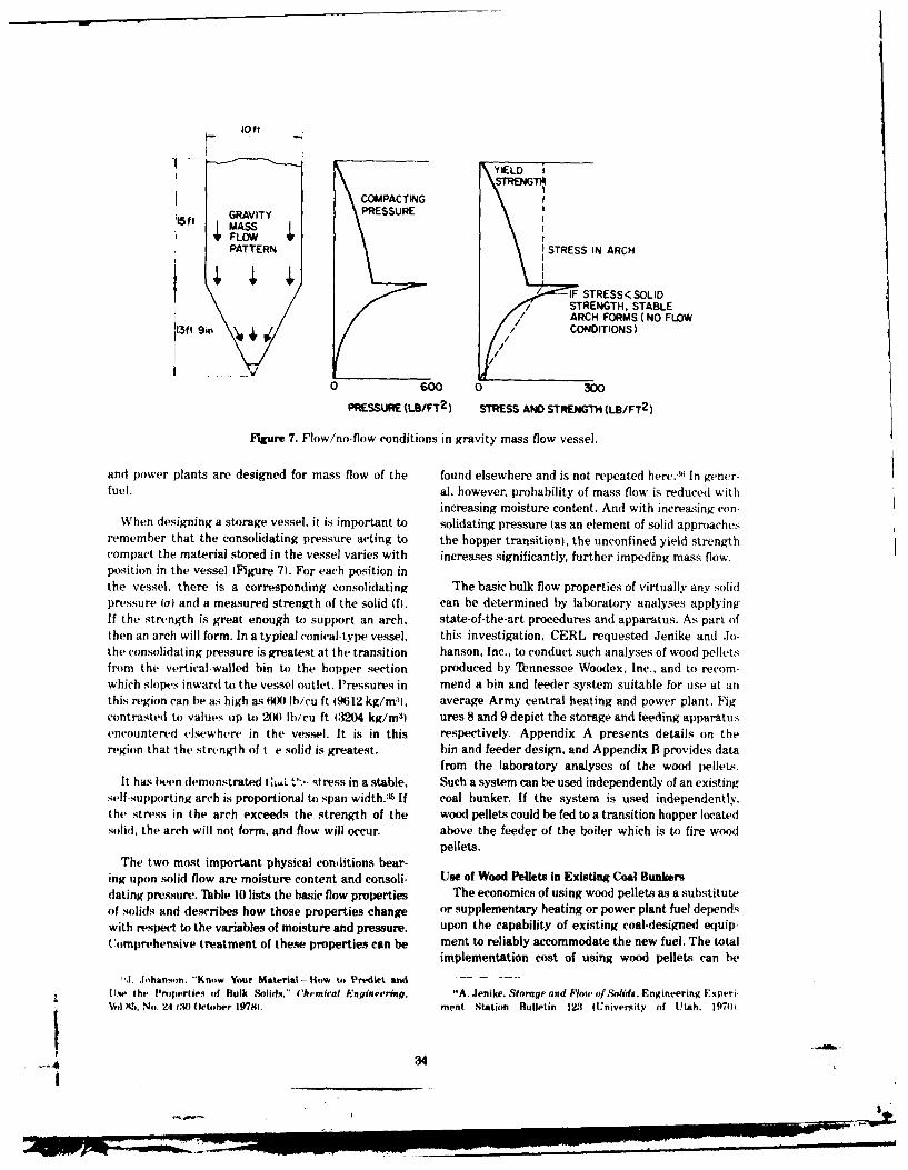
loft
IYIELD ISTRENG
COMPACTINGI,, GRAVITY PRESSURE15t ASS
FLOWI
PATTERN STRESS IN ARCH
-IF STRESS<SOLIDSTRENGTH, STABLEARCH FORMS ( NO FLOW
3f 90/ CONDITIONS)
I//
0 600 0 300
PRESSURE (LS/FT 2 ) STRESS AND STRENGTH (LB/FT 2 )
FIgure 7. Flow/no-flow conditions in gravity mass flow vessel.
and power plants are designed for mass flow of the found elsewhere and is not repeated here. :*i In gener-
fuel. al, however, probability of mass flow is reduced withincreasing moisture content. And with increasing con-
When designing a storage vessel, it is important to solidating pressure tas an element of solid approachesremember that the consolidating pressure acting to the hopper transition), the unconfined yield strengthcompact the material stored in the vessel varies with increases significantly, further impeding mass flow.position in the vessel IFigure 7). For each position inthe vessel, there is a corresponding consolidating The basic bulk flow properties of virtually any solidpressure (a) and a measured strength of the solid f. can he determined by laboratory analyses applyingIf the strength is great enough to support an arch, state-of-the-art procedures and apparatus. As part ofthen an arch will form. In a typical conical-type vessel, this investigation, CERL requested Jenike and Jo-the consolidating pressure is greatest at the transition hanson, Inc., to conduct such analyses of wood pelletsfrom the vertical-walled bin to the hopper section produced by Tennessee Woodex, Inc., and to recom-which slopes inward to the vessel outlet. Pressures in mend a bin and feeder system suitable for use at anthis region can he as high as 6I( lb/cu It 19612 kg/m:', average Army central heating and power plant. Fig-contrasted to values up to 20(0 Ibicu ft 13204 kg/m 3 ) ures 8 and 9 depict the storage and feeding apparatusencountered elsewhere in the vessel. It is in this respectively. Appendix A presents details on theregion that the strength of t e solid is greatest. bin and feeder design, and Appendix B provides data
from the laboratory analyses of the wood pellets.It has been demonstrated -A, t-', tress in a stable, Such a system can be used independently of an existing
self-supporting arch is proportional to span width. :L If coal bunker. If the system is used independently.the stress in the arch exceeds the strength of the wood pellets could be fed to a transition hopper locatedsolid, the arch will not form, and flow will occur. above the feeder of the boiler which is to fire wood
pellets.The two most important physical conditions bear-
ing upon solid flow are moisture content and consoli- Use of Wood Pellets in Existing Coal Bunkersdating pressure. Table 10 lists the basic flow properties The economics of using wood pellets as a substituteof solids and describes how those properties change or supplementary heating or power plant fuel dependswith respect to the variables of moisture and pressure. upon the capability of existing coal-designed equip-Comprehensive treatment of these properties can be ment to reliably accommodate the new fuel. The total
implementation cost of using wood pellets can be
' .l.ohanson. "Know Your Material-liow to Predict and . .Usw the Properties of Bulk Solids." ('hemical Engineering, "A. Jenike. Storage and Flou of Solids, Engineering ExperiVol. M.5, No. 24 :N) October 197MI. ment Station Bulletin 123 lUniversity of Utah, 19701.
I

total vokwo 18,000 cu.ft
h 20"-0"l 200" 0-0
15-0" - corbon steel
-- 304 stomilesssteel with a28 finish
281-7"
190
15-0" Is5s-a",o.-o., ,--.s. oFigure 8. Wood pellet storage bin.
hopper
equal length troughingidler belt feeder
collecting comter belt
Fiw 9. Wood pellet feeding apparatus.
3i
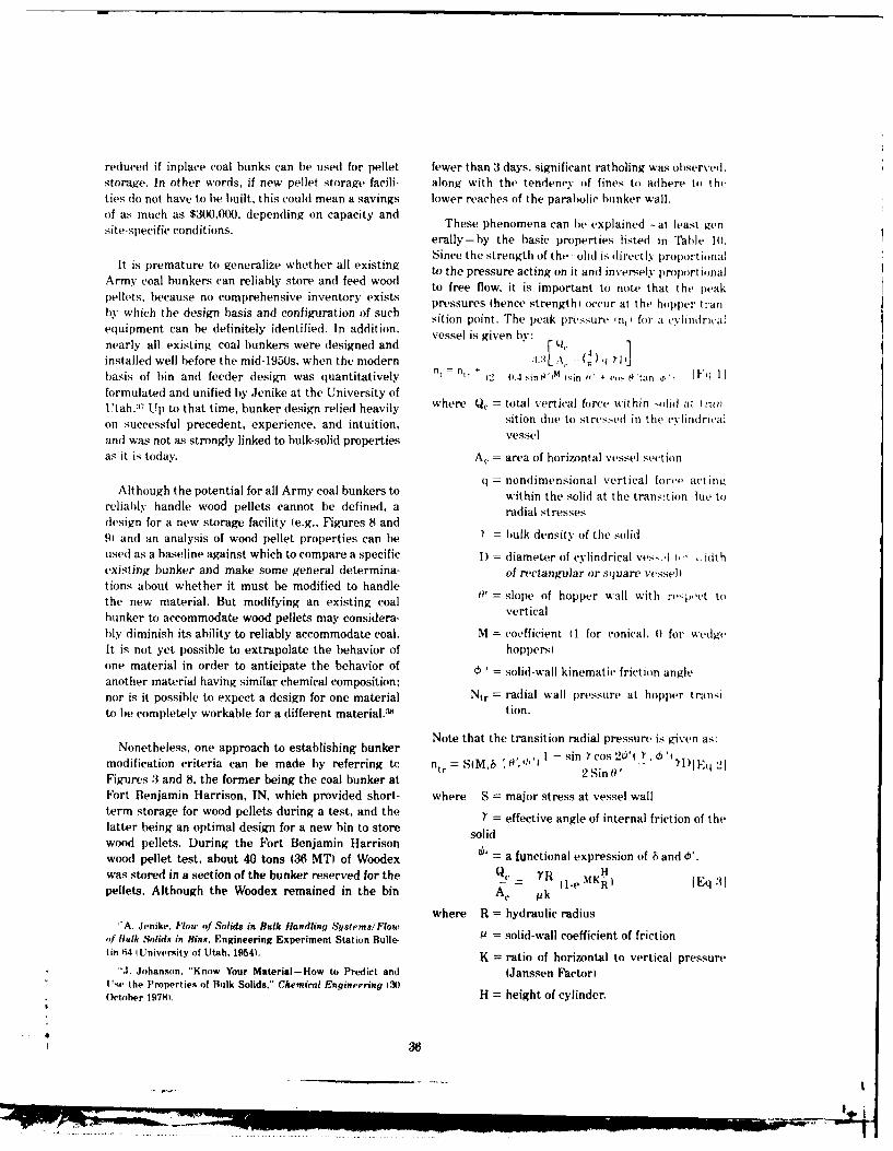
reduced if inplace coal bunks can be used for pellet fewer than 3 days, significant ratholing was observed.storage. In other words, if new pellet storage facili- along with the tendency of fines to adhere to theties (1o not have to be built, this could mean a savings lower reaches of the parabolic bunker wall.of as much as $3(X),(XX), depending on capacity andsitespeifi conitins.These phenomena can be explained -~ at least gensite-specific conditions. erally-by the basic properties listed in Table 1().
Since the strength of the 'olid is directly prop~ortionalIt is premature to generalize whether all existing to the pressure acting on it and inversely prolrtional
Army coal bunkers can reliably store and feed wood to f ure i itan tnoe thatpak
pellets, because no comprehensive inventory exists pree fhenc s t nt tc at the peakpressures (hence strngthi oc'cur at the hopper tran
by which the design basis and configuration of such sition point. The peak pressure in, for a c.vlinldricaiequipment can be definitely identified. In addition. vessel is given by:nearly all existing coal bunkers were designed and 1installed well before the mid-1950s, when the modern :1.:[A ( ) flIJ
basis of bin and feeder design was quantitatively n, = n, 2 - 11.4 sin W'M sin w v- P'tan 0', 1 Fq I
formulated and unified by Jenike at the University ofUtah. :17 Up to that time, bunker design relied heavily where Q, = total vertical force within olid at Ir.,n
on successful precedent, experience, and intuition, sition due to stressed in the cvlindrical
and was not as strongly linked to bulk-solid properties vessel
as it is today. Ac = area of horizontal vessel section
q = nondimensional vertical force actingAlthough the potential for all Army coal bunkers to within the solid at the transition lue to
reliably handle wood pellets cannot be defined, a radial stressesdesign for a new storage facility (e.g., Figures 8 and91 and an analysis of wood pellet properties can be = bulk density of the solid
used] as a baseline against which to compare a specific I) = diameter of cylindrical ves, 1 t,,' v. fithexisting bunker and make some general determina- of rectangular or sq uare vesselItions about whether it must be modified to handlethe new material. But modifying an existing coal verislbunker to accommodate wood pellets may considera- verticalbly diminish its ability to reliably accommodate coal. M = coefficient I 1 for conical. 0 for wedgeIt is not yet possible to extrapolate the behavior of hoppersione material in order to anticipate the behavior of ' solid-wall kinematic friction angleanother material having similar chemical composition;nor is it possible to expect a design for one material Ntr = radial wall pressure at hopper transi
to be completely workable for a different material.38 tion.
Note that the transition radial pressure is given as:
Nonetheless, one approach to establishing bunker N
modification criteria can be made by referring tc ntr = S(M.6 "0',',b 1 - sin Ycos 20" ')1l.Eq 2lFigures 3 and 8, the former being the coal bunker at 2 Sin 0'
Fort Benjamin Harrison, IN, which provided short- where S = major stress at vessel wallterm storage for wood pellets during a test, and the Y = effective angle of internal friction of thelatter being an optimal design for a new bin to store solidwood pellets. During the Fort Benjamin Harrisonwood pellet test, about 40 tons (36 MT) of Woodex L' = a functional expression of 8 and 6'.was stored in a section of the bunker reserved for the Qc = YR H
pellets. Although the Woodex remained in the bin A, pk
where R = hydraulic radius'-A. Jenike, Flow of Solids in Bulk Handling Systems/Flow w = sld-all cofict
of Bulk Solids in Bins. Engineering Experiment Station Bulle- 9 = solid-wall coefficient of frictiontin 64 1University of Utah, 1954). K = ratio of horizontal to vertical pressure
'"J. Johanson, "Know Your Material-How to Predict anti (Janssen Factor)I'se the Properties of Bulk Solids." Chemical Engineering 1,30O October 197M). H = height of cylinder.
-- 3~36
.... |
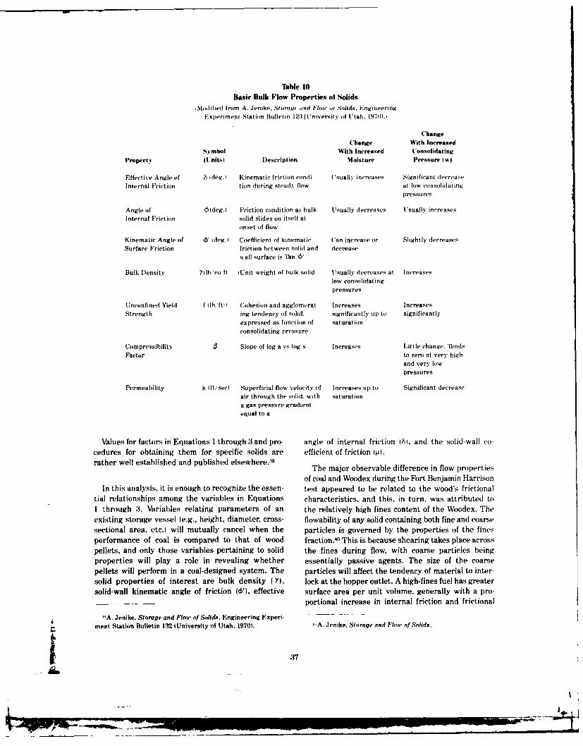
TIble 10Basic Bulk Flow Properties of Solids
,Moditied from A. Jenike. Stoiovrc aind low ot Solids, EngineeringExperiment Station Bulletin 123 tUniversity of Utah. 197(11.t
Change
Change With IncreasedSymbol With Increased Consolidating
Property lt'nitsI Description Moisture Pressure fIr
Effective Angle of 6 1deg.) Kinematic friction condi- Usually increases Significant decreaseInternal Friction tion (luring steady flow at low consolidating
pressures
Angle of Oldeg.I Friction condition as bulk Usually decreases Usually increasesInternal Friction solid slides on itself at
onset of flow
Kinematic Angle of & i deg.I Coefficient of kinematic Can increase or Slightly decreasesSurface Friction friction between solid and decrease
wall surface is Tan &
Bulk Density Yllb'cu ft iUnit weight of bulk solid Usually decreases at Increaseslow consolidatingpressures
Unconfined Yield f lbift Cohesion and agglomerat- Increases IncreasesStrength ing tendency of solid, significantly up to significantly
expressed as function of saturationconsolidating pressure
Compressibility Slope of log a vs log s Increases Little change. TendsFactor to zero at very high
and very lowpressures
Permeability k Ift/sec Superficial flow velocity of Increases tip to Significant decreaseair through the solid, with saturationa gas pressure gradientequal to a
Values for factors in Equations 1 through 3 and pro- angle of internal friction 461, and the solid-wall co-
cedures for obtaining them for specific solids are efficient of friction (p).rather well established and published elsewhere. The major observable difference in flow properties
of coal and Woodex during the Fort Benjamin Harrison
In this analysis, it is enough to recognize the essen- test appeared to be related to the wood's frictionaltial relationships among the variables in Equations characteristics, and this, in turn, was attributed to
I through 3. Variables relating parameters of an the relatively high fines content of the Woodex. The
existing storage vessel (e.g., height, diameter, cross- flowability of any solid containing both fine and coarse
sectional area, etc.) will mutually cancel when the particles is governed by the properties of the fines
performance of coal is compared to that of wood fraction. 4 This is because shearing takes place across
pellets, and only those variables pertaining to solid the fines during flow, with coarse particles being
properties will play a role in revealing whether essentially passive agents. The size of the coarse
pellets will perform in a coal-designed system. The particles will affect the tendency of material to inter-
solid properties of interest are bulk density (Y), lock at the hopper outlet. A high-fines fuel has greater
solid-wall kinematic angle of friction (0'), effective surface area per unit volume, generally with a pro-portional increase in internal friction and frictional
"A. Jenike. Storage and Flow of Solids, Engineering Experi-
ment Station Bulletin 132 1University of Utah, 1970). ,,A. Jenike, Stnrage and Flo, of Solids.
37[ :,I
resistance at the wall. The friction is further increased surface friction angle. Specific hopper angles andby the relatively fibrous nature of Woodex fines com- friction angles must be determined with respectpared to coal fines; fibrous particles tend to interlock, to the effective angle of the solid's internal friction:further increasing the internal friction angle of the that friction itself can be identified for virtuallysolid, and thereby its strength and the probability of any hulk solid using state-of-the-art laboratoryflow problems. techniques.
During the Fort Benjamin Harrison Woodex test. Such techniques must also be applied to ascertainratholes formed in the wood pellets above the hopper time-related changes of solid properties-change,outlet essentially because the hopper walls were not such as moisture migration and temperature in-steep enough to cause the material to flow down crease. Ilt is expected that changes due to chemicalthem. A rathole will be stable when the stress in its reaction and deaeration will be virtually nonexi-walls is less than the strength of the solid, and when tent with wood pellets.) Changes in moisture con-the stress exceeds the solid's strength. the rathole tent can be caused by factors such as contaminationwill fail and flow will x'cur. At Fort Benjamin Harrison, of the fuel by rainfall, the hydroscopicity of thethe rathole occurred in a region extending upward fuel, and the corresponding rate at which it picksabout 10 ft (3.1 m) from the 2.5 ft by 2.5 ft (0.8 by 0.8 up water from ambient atmosphere. Even subtleml hopper outlet. Were the outlet larger, the flow changes in moisture content can significantly affectchannel would have been proportionally greater, the the frictional properties of the solid. R'mperaturestress in the rathole would have been larger, and the effects can include freezing of moisture in the mate-position at which the rathole was unstable would rial (resulting in ice bondingi and overheating. Therehave been lower. Since the stress in the solid is s will give off heatproportional to the diameter of the rathole, enlarging during moderate-term storage, as does refuse-derived
the hopper outlet to a point where stress exceeds the fuel (in large part due to biodegradationi. With the
solid strength would have allowed good flow. More- epin fre p osbili ties te i n hi
over, rathole obstructions to gravity mass flow will not ecett tmereeill sigiitly affe se(Iformwhe hoper lops ae step nd moot enugh dence that temperature will significant ly affect use ofform when hopper slopes are steep and smooth enough wood pellets. Normally, time-related effects on the
to cause flow along them. Mass flow design is hence a flowability of a solid re simulated in the laboratory
function of the solid-wall friction angle ( o')4 There- and directly influence the design and/or modificaton
fore, a second modification for wood pellet storage of storage equipment.
at Fort Benjamin Harrison would involve increasing
the slope and eliminating the curvature of the para-bolic bunker, either by reconstruction or by placing A significant factor affecti|ig solid flow properties
inserts in it. is overpressure. In normal handling, wood pellets aresubjected to vibration, impact, and external loading.
A limiting relationship thus exists between the These actions add to the total compacting pressure tofriction angle (W) and the conical half angle of the which the material is subjected. Traditional flowabilityhopper, as measured from the vertical. Since the fric- analyses consider only gravitational forces from thetion angle varies with normal pressure on the solid, weight of the material. If overpressure does not com-that angle's position changes within the hopper. The pound the effect of gravity, there is no change inlimiting relationship between the friction angle and critical storage vessel dimensions. Increased compac-the half angle of the hopper is functionally related to tion, however, can significantly increase the tendencythe effective internal friction angle (a) of the solid, of some solids to arch in a hopper. In DOD woodFor solids such as the Woodex tested at Fort Benjamin pellet tests, the pellets were subjected to a varietyHarrison (multiple sieve sizes, high in fines) where of overpressure forces between the time they werethe internal friction angle can be relatively great produced and the time they were fired. At Fortcompared to coal, the critical hopper angle will decrease Benjamin Harrison, it was observed that a significantIto approach W, or vertical) linearly with increasing fraction of the delivered pellets lost their structural
integrity because of high shear forces at the point
1.J. Johanson, "Know Your Material-ilow to Predict and where the fuel-receiving hopper discharged by grav-Use the Properties of Bulk Solids," Chemical Engineering (,30 ity to an elevating transition conveyor. The net resultOctoher 197M) was an increased fraction of fines in the material
38
imlmmmlm l lmlll mm m m ( an lm~ mm u lmm mm mmm m mlmlm

which was delivered to the hunker. With wood pel- 5 COMBUSTIONlet,; these conditions cumulatively led to increasedsolid strength and doubtlessly contributed to thetendency of the material to rathole in the bunker; Generalcoal, however, is affected insignificantly luring normal As in the case of handling, storage, and feeding
operation at Fort Benjamin Harrison. equipment, the capability of an existing boiler to firesubstitute or supplemental wood pellets partially
Hence. at any location considered for wood pellet determines the cost-effectiveness of their use. In the
use, it is not enough to know only the material ideal case, wood pellets could completely substitute
properties of pellets on an as-produced basis in order for coal with no modifications to or changes in per-
to project how well they can be stored and handled in formance of the combustion hardware. Such has not
an existing bunker. Rather, the design and/or modifi- been entirely the case in experience with wood pel-
cation of a storage facility must consider the changes lets to date, but their performance has been lar from
in the properties of the bulk pellets as they pass from unsatisfactory as a substitute in boilers designed for
their site of production to the point they enter the coal. In this chapter, some of the major factors limiting
boiler. Because of the site-specific nature of fuel wood pellet use in existing boilers are discussed.
systems Army-wide, only general guidelines can be
offered for the reliable handling and storage of woodpellets; and their use-whether as a substitute fuel Fuel Composition and Characteristicsor mixed in some proportion with coal-must be As indicated earlier in Table 6, wood and wooddetermined on a case-by-case basis. products are highly oxygenated fuels with about two-
thirds the energy content of coal; softwoods gener-
Summary ally contain more energy than hardwoods dry weight
Although handling and storage technology limits basis) because of higher lignin (therefore carbon ('on-
the scale at which wood can be used as a fuel, it is tent and the presence of more resins in the extrav
evident that potential installation-scale wood pellet tions. Wood is a composite of three basic polymers:
systems are small enough to be free of such restric- cellulose (CH5(),l, lignin iCQHi0(.i IOCH: ,, 1
tions. Conventional, long-proven technology exists for and hemicelluloses such as xylan (C:.,Hm( 41. There arc
handling and storing hogged wood and wood chips at usually only minor quantities of extractives and min-
the scale at which an average installation will use erals (ash). Most hydrocarbon fuels, including coal.
them. Where required, advanced concepts for enclosed are parafinic and can be represented by the general
storage of such materials appear to be technically formula )CH.)n; an appropriate similar representation
feasible but will add to the cost of producing and/or for wood is CHn(H0)nm. In general, hardwoods contain
using wood pellets, by weight about 43 percent cellulose, 22 percent ligninand :35 percent hemicelluloses (extractive-free basis),while softwoods contain equal cellulose, 29 percent
The design of a bin and feeder system to reliably lignin and 28 percent hemicellulose. In general, theaccommodate wood pellets in quantities appropriate heating value of the fuel increases in direct proportion
for installation-scale use is achievable using state-of- toatsngigainecontet.rt
the-art techniques and procedures to determine and
apply critical properties of bulk materials. Suchtechniques and procedures should also be applied to The relation of solid fuel properties to their corn-determine on a case-by-case basis whether existing bustion performance for several firing methods iscoal storage equipment can be used either unchanged, shown in Thble 11.43 Such information must be con-
or with modification, to accommodate pellets. The sidered when evaluating an alternate fuel for an
essential, design-related properties of wood pellets existing heating or power plant. For traveling-gratecan be determined and appear to be different from (overfeed) and spreader-stoker applications, the rela-
those of most coals. Nevertheless, there is everyreason to believe that through application of modern -I). "illman. Wmed as an Energy Resource I Academic Press.
engineering principles and practices a reliable wood 1978 .pellet handling, storage, and feeding system (either a 'IS. A. Hathaway and R. J. I)ealy, Technoloay Ev'aluati,n ,,.1new vessel or a modified existing bunkerl can be Army-Scale Waste-to-Eneroy Systems. Interim Report E-IIdesigned and constructed for installation-scale use. AI)A042578 I(CRL. July 1977).
t
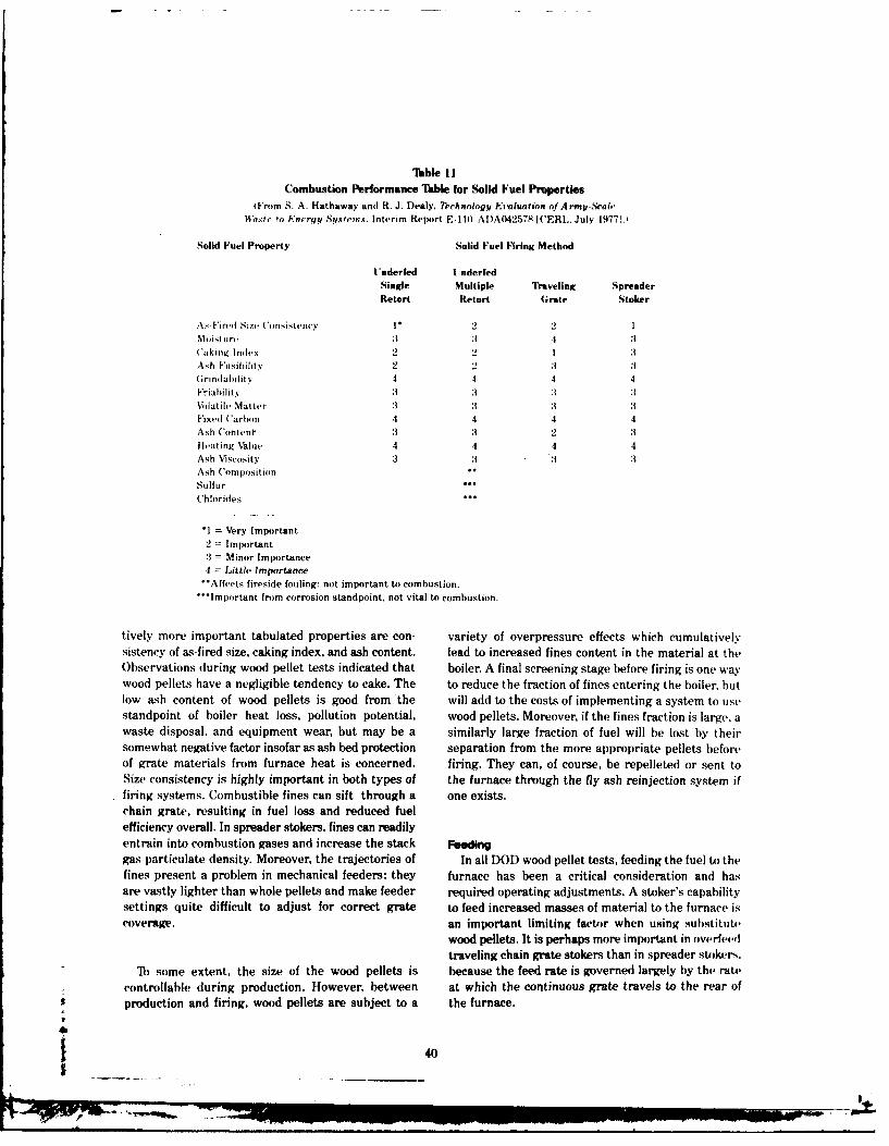
Table I ICombustion Performance Table for Solid Fuel Properties
From S. A. Hathaway and R. J. I)ealy. TDchnolog. Evaluation of A rmy-ScacWa.st-to-Knergy Systcms. Interim Report E 111t A DA042578 WCERL. July 1977 1.,
Solid Fuel Property Solid Fuel Firing Method
Underfed UnderfedSingle Multiple Traveling SpreaderRetort Retort (;rate Stoker
A.- IFi redI Size ton sistency .V2 2 1Nloistlrv :1 3 4 :3Caking Index 2 2 I :1Ash Fusibility 2 -2 :1 :1(rindabilit v 4 4 4 4Friability 3 3 :1 3Volatile Matter 3 :3 3 :3Fixed (arbon 4 4 4 4Ash Content :3 3 2 :3Heating Value 4 4 4 4Ash Viscosity 3 :3 3 3Ash ('omposition
fur fur
Chlorides ...
*1 = Very Important2 = Important.3 = Minor Importance4 = Little Importance-Affects fireside fouling: not important to combustion.
'Important from corrosion standpoint, not vital to combustion.
tively more important tabulated properties are con- variety of overpressure effects which cumulativelysistency of as-fired size, caking index, and ash content. lead to increased fines content in the material at theObservations during wood pellet tests indicated that boiler. A final screening stage before firing is one waywood pellets have a negligible tendency to cake. The to reduce the fraction of fines entering the boiler, butlow ash content of wood pellets is good from the will add to the costs of implementing a system to usestandpoint of boiler heat loss, pollution potential, wood pellets. Moreover, if the fines fraction is large, awaste disposal, and equipment wear, but may be a similarly large fraction of fuel will be lost by theirsomewhat negative factor insofar as ash bed protection separation from the more appropriate pellets beforeof grate materials from furnace heat is concerned, firing. They can, of course, be repelleted or sent toSize consistency is highly important in both types of the furnace through the fly ash reinjection system iffiring systems. Combustible fines can sift through a one exists.chain grate, resulting in fuel loss and reduced fuelefficiency overall. In spreader stokers, fines can readilyentrain into combustion gases and increase the stack Feedinggas particulate density. Moreover, the trajectories of In all DOD wood pellet tests, feeding the fuel to thefines present a problem in mechanical feeders; they furnace has been a critical consideration and hasare vastly lighter than whole pellets and make feeder required operating adjustments. A stoker's capabilitysettings quite difficult to adjust for correct grate to feed increased masses of material to the furnace iscoverage, an important limiting factor when using substitut,
wood pellets. It is perhaps more important in ov.rf,.4dtraveling chain grate stokers than in spreader stokers.
1) some extent, the size of the wood pellets is because the feed rate is governed largely by the ratecontrollable during production. However, between at which the continuous grate travels to the rear ofproduction and firing, wood pellets are subject to a the furnace.
___40
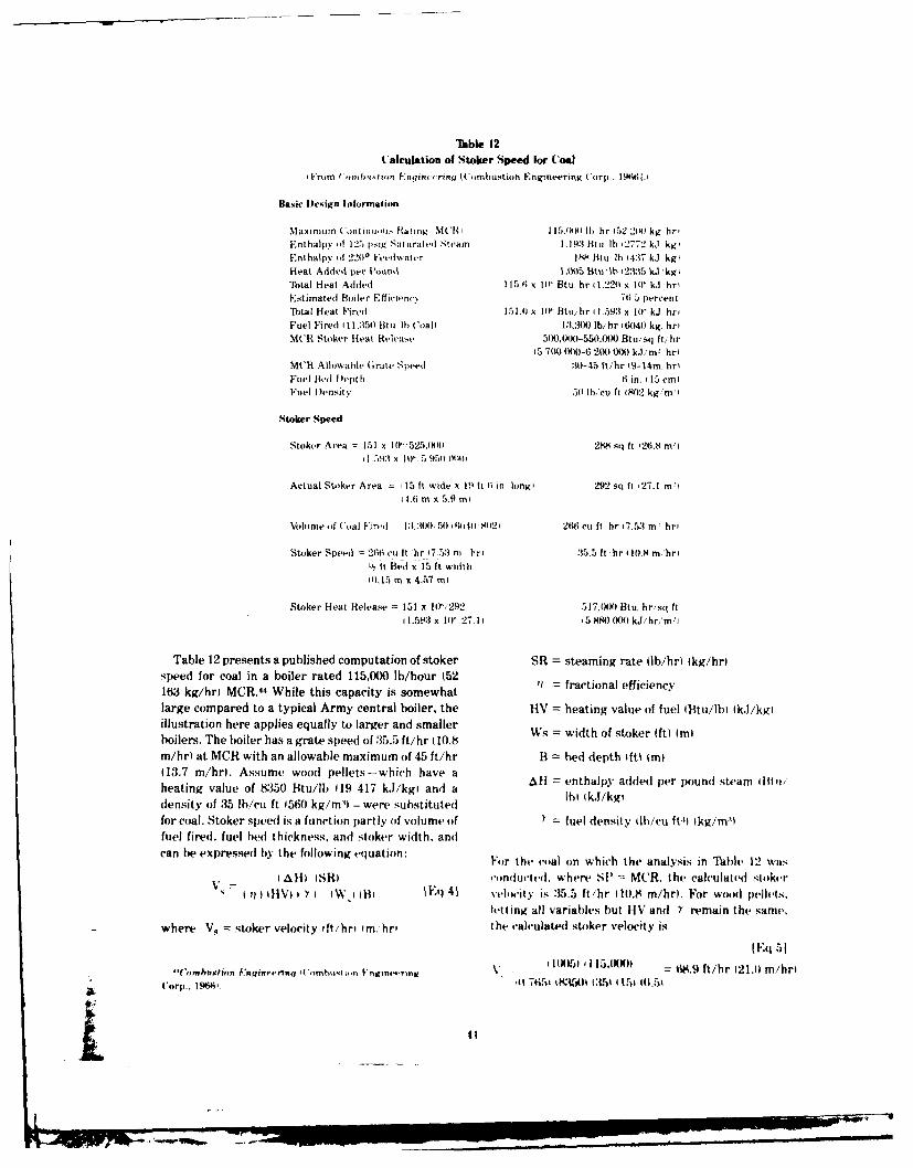
Table 12Calculation of Stoker Speed Ior Coal
Vrom (',onhwlusn Fnqu no,'rag I mustoo Engineering 'or p.. 14611
Basic Design Iilormaition
Maximum (ontinui Rating Mt(IR 1 15.00) lb hr 2 2100 kg hr,Enthalpy oi 125 iig Saturated Steam 1.193 Btu lh i2772 kJ kg'Fnthalpy of 220 Feedwater I M fiu lb 4:37 kJ kg'Heat Added per Pound ,t)5 Btu 'b 312*3,5 k kg'Total Heat Added 115.6 x t' Btu, hr ;1.220 % I)' k'hrlEstimated Boiler Effijieney 761.5 percentTotal Heat Fired 151.0 x I0' Btu/ hr 11.5913 x 10 kJ hriFuel Fired I 11,350 Btu Ib ('oal 13,300 lb/hr 16040 kg. hriM('R Stoker Heat Release 5X),000-550,0(00 Btu/sq Ift/hr
t5 700 (00-6 200 (0) kJ/m' hrIM('R Allowable (rate Speed 30-45 It/hr l9-14m hriFuel Bed Depth 6 in. 15 cmIFuel Density 50 lbicu ft 1802 kg/m'i
Stoker Speed
Stoker Area - 151 x 10'52'5.0(0 288 sq ft 26.8 mi
1.57,93 x 101 5 951) (1lilt
Actual Stoker Area : 15 it wide x 11) it i in. longi 292 sq ft 127.1 m'4.416 m X 5.9 mI
Volume of toal Firtei 13.:300, 50 'liot ) 8021 2W6 cu ft, hr 17.53 m hri
Stoker Speed = 266 cu It 'hr 17.53 m hri 35.5 It hr 110.8 m'hrtL', it Bed x 15 1t wdtht, o m x 4.57 m I
Stoker Heat Release = 151 x 1("/292 517.(X)0 Btu hr/sq ft11.593 x 10 27.11 '5 S0 00) kJi'hr,'nim'
Table 12 presents a published computation of stoker SR = steaming rate llb/hr) tkg/hr)speed for coal in a boiler rated 115,000 lb/hour (521433 kg/hrl MCR.44 While this capacity is somewhatlarge compared to a typical Army central boiler, the HV = heating value of fuel lBtu/b) ki/kgillustration here applies equally to larger and smallerboilers. The boiler has a grate speed of :35.5 ft/hr 10.8m/hr at MCR with an allowable maximum of 45 ft/hr B = bed depth ft 1m)13.7 m/hrL Assume wood pellets-which have a enthalpy added per pound steam Otto/
heating value of 83510 Btu/lb 19 417 k.J/kgl and a N k.Iikgdensity of 35 lb/cu ft 1560 kg/m:u- were substitutedfor coal. Stoker speed is a function partly of volume of = fuel density (lh/cu ft:1 Ikg/m:Pfuel fired, fuel bed thickness, and stoker width, andcan be expressed by the following equation: Fr the coal on which the analysis in Th., 12 was
l alfi (SR) conducted. where SP = MUR. the calculated stokerI ) ( I11VI I I B 141 Ell 41 vtlOwity is :15.5 ft/hr I)10.8 m/hr). For wood pellu'ls.
letting all variables but HV and Y remain the same.
where V, ;toker velocity ffti!hr tim, hr the calculated stoker velocity is
(Eq 51"('omhustin b.'I nuu6n1'1 I'uunuoq Iii Fngune.ring . l(1 €115.INW) 1*.9 ft/hr 21.0 m/hri
Corp.. 194h 651t 1 M35ro1 CL51 1i1s (0.. 1
m
4t I
This is approximately 53 percent greater than the pellets is inescapably linked to the production tech-
allowable maximum travel rate under the design con- nology used to dry and compact wood into a substitute
ditions stated for coal. Since the grate travel speed in fuel.traveling grate stokers essentially represents the fuel
feed rate, it is clear that it is a limiting factor governing
the maximum load at which a boiler can operate Reactivity
continuously when using substitute wood pellets. When a solid fuel such as coal or wood is fed to afurnace, a process involving several steps begins.
The extent of derating can be estimated by rear- First, the material dries (evaporation of moisture,
ranging Equation 4 to solve for SR with V, n 35.5 which represents a heat loss in the system). This isiable 12, and letting the fuel energy density EDI = followed by volatilization, ignition of volatiles, free
HV V) Y. Then combustion, and char burnout. For a given piece offuel, the steps sometimes can be considered as separate
IS )) WE ) 61 (VI stages; but in any given area of the furnace containingSR [Eq 6]
Ali a significant mass of fuel, all steps may be takingplace simultaneously.
For wood pellets, SR =59 230 lb/hr (26 866 kg/hr). The rate at which wood pellets might be expected
representing a derating of about 48.5 percent. to burn is very generally indicated by the fuel chem-
One way of reducing the derating is to increase the istry data shown in Table 6. Wood pellets are sub-
fuel bed depth (B) and increase the rate of fuel feed stantially higher in volatile matter than coal, and(as represented here by grate travel rate [Vs]) to its contain far less fixed carbon per unit weight. One
maximum. Letting V, = 45 ft/hr (13.7 m/hrl and would expect, therefore, that overall combustion of
B = 0.67 ft (203 mm), about the maximum bed depth the pellets would emphasize gas-phase combustion of
allowable in most systems, Equation 6 reveals an volatiles, while that of coal would place less emphasis
MCR of 100,607 lb/hr (45 635 kg/hr), representing a on volatiles and somewhat more on fixed carbon com-
derating of about 12.5 percent. This analysis presumes bustion and burnout stages. In wood, the content of
that there will be no loss in efficiency IrYp when using cellulose and hemicellulose principally promotes the
substitute wood pellets, while test experience to date release of volatiles, while lignin, which also releases
indicates efficiency drops of up to 10 percent at least. volatiles, primarily promotes char formation. Lignin
Letting r = 0.665 and solving Equation 6 for SR = content ranges between 18 and 33 percent by weight.
MCR, a value of 87,456 lb/hr (39 669 kg/hr) is com- while cellulosic materials account for 65 to 70 percent
puted, representing a derating of about 24 percent. of the total mass.45
Similar analyses can be performed to determine Several studies have reported that the combustion
feeder turnup rates for spreader stokers, and similar properties of wood and wood pellets are significantly
conclusions can be reached. It is important to note different from those of most coals. Kochler reported
that the extent of derating depends on factors such as in 1924 that air-dried wood (with 12 to 15 percent
changes in boiler radiative and convective heat transfer moisture, similar to wood-pellet material) required
rates, as well as on feed-related phenomena. In this less than 1-minute residence time before ignition in
analysis, it is clear that the extent of derating is thermal environments not unlike those prevailing in
dependent on how far the boiler is pushed with respect boilers (707 0 F [3750 C] and greater).4 More recently,
to its maximum operating conditions. The closer to Shafizadeh and DeGroot showed that the energy
these conditions it is continuously operated, the less required to obtain ignition of dry cellulose at 575*F
flexibility it has to adjust to problems such as fluc- (302*C is about 225 Btu/lb (523 kJ/kgI, and the net
tuations in fuel quality, heat release is about 5070 Btu/lb (11 970 kJ/kg). Forcellulose containing 50 percent by weight moisture at
In aiddition, the extent of derating is directly 600*F (316 0C) the respective values are about 1450
proportional to the type of fuel. As noted previously,
the energy density of wood pellets is higher than 44). 1Tllman. Wood as an Energy Resource I Academic Press,
that of wood chips and hogged wood, but still only 19781.
about 57 percent that of coal. Hence, the effectiveness 'A. Koehler, The Properties and Uses of Wood NicGra%by which existing coal-designed boilers can use wood Hill, 19241.
42
L4

lltu/b :1372 k.J/kg) energy input for ignition and evaluated with respect to their potential performabout 37110 Btu/Ili 171:3! k.1/kg) nct heat release. 7 ante when firing wood pellets, since their configlraStudies by the Army and the Pittsburgh Energy Re- tions may not be conducive to affordable wood pelletsearch Center clearly indicated that highly cellulosic use.fuel materials-such as wood, paper and refuse-derived fuel-volatilized and ignited in typical fur- Combustion Stoichiomotrynace thermal environments up to 12 times more rapidly The highly oxygenated character of wood pelletsthan bituminous coal, and that the temperature compared to coal is illustrated in the ultimate analy-required for coal ignition at a given furnace residence sis presented in Table 13. While the pellets havetime was about 302*F (1500(1 greater than that about :38 percent oxygen by weight, the example coalrequired for ignition of the cellulosic fuels. has only 6.2 percent, or approximately 17 percent as
Based on these studies, it appears that the rate of much.'"
wood pellet volatilization and ignition can be a signifi- The high oxygen content of this fuel, combinedcant limiting factor governing the feasibility of pelletuse as a substitute boiler fuel, particularly where feed- with he ler ms fr sulpur wd pltoing is concerned. It was demonstrated earlier in this gen. has led to optimisim for substitute wood pellets.repot trouh rlatvel coase nalsistha, bsed When substituting low-grade fuels in existing boilers.report through relatively coarse analysis that, basedflow rate of theon overall stoker heat release requirements, some acomnpoemitevlu trcfwrtefth
on oeral soke het rleas reuirmens, ome combustion products and the attendant effect increasedboiler derating will occur when using substitute wood c outi s an heatteanfe c ncasedpellets because of the large mass flow rate of fuel gas velocities have on heat transfer and fan capabili-
ties.51 The data in Table 13 indicate that the combus-required Ip. 421. Because the wood pellet's rate of con- tion products from burning wood pellets are moresumption may be far more rapid than that of cot,', the than 40 percent less than from burning an equal massrequired fuel mass flow rate may be even greater, of coal. Because wood pellets themselves contain awith proportional sacrifice of boiler load. Further- large fraction of the oxygen required for combustion.more, since cellulosic materials require lower overall there is-compared to coal - correspondingly less com-ignition and combustion temperatures than coal, there bustion air which must be externally supplied. Thewill be an attendant change in mean furnace tm- low sulphur content of wood pellets allows more effi-peratures with possible shifts; in relative duty be- cient use of oxygen in combustion because much moretween radiant anI convective heat transfer sections.Such a shift was recorded during the Woodex test at oxygen cd the man fueloon-Fort Benjamin Ilarrison as reported earlier in thisreport, with suspected corresponding loss in overall However, because of the relatively lower heatingefficiency. value of wood pellets, a greater mass of pellets than
It is important to understand that any boiler per- coal must be fed to the furnace to maintain a givenformance changes to he expected with wood pellets heat release rate. For example, the data in Table 1:3depend on the design of the boiler. Some boilers may indicate that the coal mass flow rate to the boiler is
have been designed for a highly volatile, highly reactive 13,300 lb/hr (6033 kg/hr). Tb maintain an equivalent
coal, in which case rating sacrifices when using fuel heat release rate with pellets having a heating
substitute wooI pellets may not be large. Units value of 8350 Btu/Ib (19 417 kJ/kg) would require a
designed for a less reactive fuel must be carefully pellet mass flow rate of 18,084 lb/hr (8203 kg/hrl,which is approximately 1.36 times the coal mass flowrate. Using data from Table 13 as a general illustra--'F. Shafizadeh and W. DeGroot, "Thermal Analysis of Forest tion, one finds that the mass flow rate of combustion
Fuels.' Fuels and Energy from Renewable Resources lAca-
demic Press. 19771. product when firing coal at this rate would be 178,220
"Reactivity and Gasification Characteristics of Lou' Ranking lb/hr (80 839 kg/hr) compared to 141,055 lb/hr 63Coals and Potentially Reducing Waste Materials. PERC/RI-76/2 981 kg/hr) when firing wood pellets, using 25 percent(Pittsburgh Energy Research Center Report, 19761; S. A. Hatha- excess air under both conditions. Theoretically, then.way and J. S. Lin. "Combustion Rates of RDF," Proceedings ofThird International Conference on Environmental Problems inthe Extractive Industries (Wright Corp., Dayton, OH. 19771;S. A. Hathaway and J. S. Lin, Thermogravimetric Analysis of "Assessment of the Capability of Piring Clean Low B7"1VSolid Refuse-Derived Fuels and Coal, Technical Report E-149/ Gases in Existing Coal, Oil and Gas-Fired Steam Genrators.ADA067829 (CERL. March 1979). PB 248328 (Combustion Engineering Corp.. 19751.
43
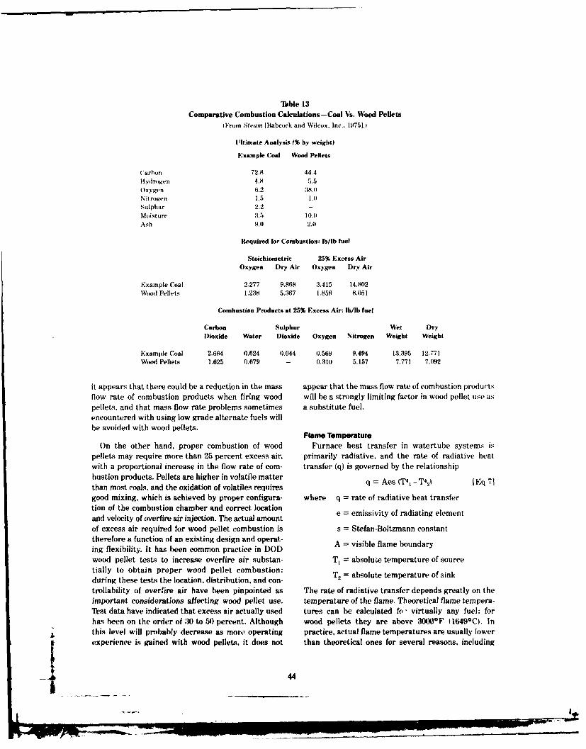
Table 13Comparative Combustion Calculations-Coal Vs. Wood Pellets
iFrom Steam lBabcock and Wilcox. Inc.. 19751.1
Ultimate Analysis 1% by weight)
Example Coal Wood Pellets
('arhon 72.8 44.4Hydrogen 4.8 5.5Oxygen 6.2 3M.0Nitrogen 1.5 1.0Sulphur 2.2 -Moisture 3.5 10.0Ash 9.0 2.0
Required for Combustion: lb/lb fuel
Stoichiometric 25% Excess AirOxygen Dry Air Oxygen Dry Air
Example Coal 2.277 9.868 3.415 14.802Wood Pellets 1.238 5.367 1.858 8.051
Combustion Products at 25% Excess Air: lb/lb fuel
Carbon Sulphur Wet DryDioxide Water Dioxide Oxygen Nitrogen Weight Weight
Example Coal 2.664 0.624 0.044 0.569 9.494 13.395 12.771Wood Pellets 1.625 0.679 - 0.310 5.157 7.771 7.092
it appears that there could be a reduction in the mass appear that the mass flow rate of combustion productsflow rate of combustion products when firing wood will be a strongly limiting factor in wood pellet use aspellets, and that mass flow rate problems sometimes a substitute fuel.encountered with using low grade alternate fuels willbe avoided with wood pellets.
Flame Temperature
On the other hand, proper combustion of wood Furnace heat transfer in watertube systems ispellets may require more than 25 percent excess air, primarily radiative, and the rate of radiative heatwith a proportional increase in the flow rate of com- transfer (q) is governed by the relationshipbustion products. Pellets are higher in volatile matter q Aes (T4
1 - T42( lEq 71than most coals, and the oxidation of volatiles requiresgood mixing, which is achieved by proper configura- where q = rate of radiative heat transfertion of the combustion chamber and correct locationand velocity of overfire air injection. The actual amount e emissivity of radiating elementof excess air required for wood pellet combustion is s = Stefan-Boltzmann constanttherefore a function of an existing design and operat- A = visible flame boundarying flexibility. It has been common practice in DODwood pellet tests to increase overfire air substan- T, = absolute temperature of sourcetially to obtain proper wood pellet combustion: T, = absolute temperature of sinkduring these tests the location, distribution, and con-trollability of overfire air have been pinpointed as The rate of radiative transfer depends greatly on theimportant considerations affecting wood pellet use. temperature of the flame. Theoretical flame tempera-Test data have indicated that excess air actually used tures can be calculated fo- virtually any fuel: forhas been on the order of 30 to 50 percent. Although wood pellets they are above 3000*F (1649*C). Inthis level will probably decrease as more' operating practice, actual flame temperatures are usually lowerexperience is gained with wood pellets, it does not than theoretical ones for several reasons, including
44
heat losses, quenching, and the viscosity-temperature surface effects attributable to pellet firing. In gener-relationship of ash. ai. experience has been highly positive, with person-
nel at Kingsley AFB and Fort McCoy reporting overall
In DOD wood pellet tests, flame temperatures decreased wear on surfaces and auxiliaries, such asranged between 2200F and 2450*F (12(4*C and fans, and corresponding levels of maintenance well13430C1 for wood pellets and between 2300*F and below those normal with coal. Moreover, since wood2600 0 F 1126()0 C and 1427 0 ) for bituminous coal. As pellets are lower in chlorides and sulphur, it is expectedindicated by Equation 7, even a small change in flame that less corrosion damage will occur.temperature can strongly affect the radiative heattransfer rate, since the absolute temperature of the Unfortunately, with respect to the thermochemicalflame is raised to the fourth power. Because of this, a and thermophysical properties of wood pellet ash,decrease in flame temperature can be expected to there seems to be no data by which to project theeffect a more than proportional decrease in radiative effects pellet firing will have on surfaces over theheat transfer rate. all other variables assumed to be moderate and long term.constant. Therefore, the role of radiative transfer canbe expected to diminish somewhat when firing woodpellets as a coal substitute. Auxiliaries
To date, the effects that wood pellets have had onThe degree to which a decrea.c of any magnitude heating and power system auxiliaries have been
in the radiative heat transfer rate will affect overall entirely positive, and this has been attributed to thesystem heat transfer is a function of existing design. low ash content of the fuel. In fact, sootblowers and
Reduction in radiative transfer might be fully com- fans have benefited most from the use of wood pel-pensated for by an increase in the rate of heat transfer lets.in the convective section. Such a relative shift of dutywas observed during Woodex tests at Fort Benjamin The number and location of sootblowers are deter-Harrison, but the increase in the convective heat Tenme n oaino otlwr r ltrtrronsfertrte din aper t copeatie ully f mined by the fuel's ash content and the ash's fusiontransfer rate did not appear to compensate fully for temperature. In DOD experience with wood pelletslost radiative transfer. Continually high flue gas so far, there has been a dramatic decrease in thetemperatures during the Fort Benjamin Harrison test frequency of sootblowing, principally because of thesuggested that an enlarged convective heat transfer fuel's low ash content and the tendency of that ash tosurface area would lead to more efficient fuel use andminimize any possible boiler derating due to changedheat transfer patterns. Another modification at FortBenjamin Harrison would involve retubing the fur- Forced draft (FD1 fan size is determined partly by
nace with tubes sized and spaced appropriately to fuel and air moisture content and downstream temper-
achieve the design basis radiative rate and convec- ing air requirements. With higher moisture content.
tive inlet temperatures. Such a modification would be less tempering air is admitted downstream and more
tantamount to increasing the radiative heat absorb- air must be directly forced into the furnace through
ing surface area- fortunately, the wood's lower ash the FD fan. While the moisture content of wood
content and its tendency to foul noticeably less would pellets is higher than that of coal, all FD fans at D))
permit furnace tubes to be more closely spaced than wood pellet test sites have clearly demonstrated their
appropriate with many coals. capability to perform adequately when pellets havebeen used.
Surtme Effects Ash loading and composition directly influenceFor a central heating or power boiler to function induced draft (ID) fan selection and performance. In
satisfactorily, internal surfaces must be kept clean general, the low ash content of the wood pellets
and intact. Slagging, fouling, and corrosion are dele- has meant reduced ID fan power consumption and
terious and result in poor system performance and attendant decreases in boiler plant electrical power
decreased fuel economy. consumption. No significant problems have beenencountered in any wood pellet test with respect to
1)0)) tests with wood pellets have been too brief to ID fan capability to provide adequate draft even at
identify any but the most immediately observable comparatively high levels of turndown.
1 _ 45| °.
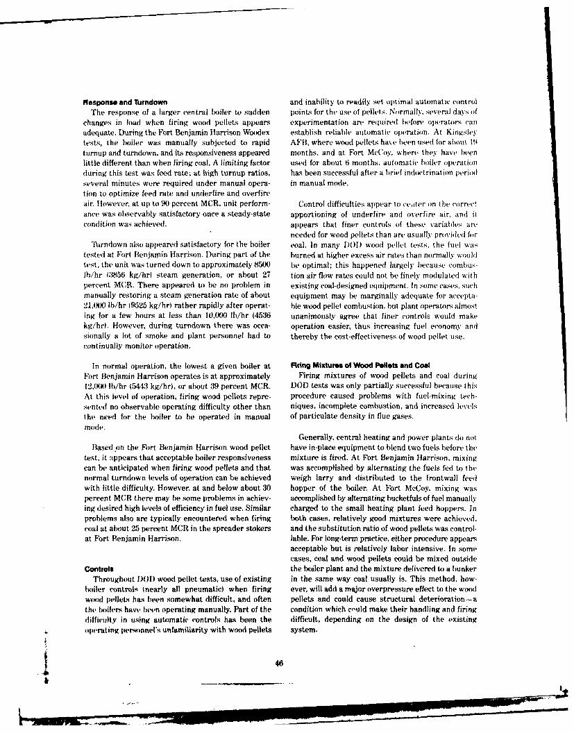
Response and Turndown and inability to readily set optimal automatic control
The response of a larger central boiler to sudden point-s for the use of pellets. Normally. several days ofchanges in load when firing wood pellets appears experimentation are required before operators caIn
adequate. During the Fort Benjamin Harrison Woodex establish reliable automatic operation. At Kingsley
tests, the boiler was manually subjected to rapid AFB, where wood pellets have been used for a0out 19turnup and turndown, and its responsiveness appeared months, and at Fort McCoy, where they have beenlittle different than when firing coal. A limiting factor used for about 6 months, automatic boiler operation
during this test was feed rate; at high turnup ratios, has been successful after a brief indoctrination period
several minutes were required under manual opera- in manual mode.
tion to optimize feed rate and underfire and overfireair. However, at up to 90 percent MCR, unit perform- Control difficulties appear to ce.iter on the correct
ance was observably satisfactory once a steady-state apportioning of underfire and overfire air, and itcondition was achieved, appears that finer controls of these variables are
needed for wood pellets than are usually provided for'hirndown also appeared satisfactory for the boiler coal. In many )O)D woo(d pellet tests, the fuel was
tested at Fort Benjamin Harrison. During part of the burned at higher excess air rates than normally wouldtest, the unit was turned down to approximately 8500 be optimal; this happened largely because combus-lb/hr (3856 kg/hrl steam generation, or about 27 tion air flow rates could not be finely modulated withpercent MCR. There appeared to be no problem in existing coal-designed equipment. In some cases, such
manually restoring a steam generation rate of about equipment may be marginally adequate for accepta-21,040 lb/hr (9525 kg/hrl rather rapidly after operat- ble wood pellet combustion, but plant operators almosting for a few hours at less than 10,000 lb/hr (4536 unanimously agree that finer controls would makekg/hr(. However, during turndown there was occa- operation easier, thus increasing fuel economy andsionally a lot of smoke and plant personnel had to thereby the cost-effectiveness of wood pellet use.continually monitor operation.
In normal operation, the lowest a given boiler at Firig Mixtures of Wood Pellets and CoalFort Benjamin Harrison operates is at approximately Firing mixtures of wood pellets and coal during12.00 lb/hr (5443 kg/hr), or about 39 percent MCR. DOD tests was only partially successful because thisAt this level of operation, firing wood pellets repre- procedure caused problems with fuel-mixing tech-sented no observable operating difficulty other than niques, incomplete combustion, and increased levelsthe need for the boiler to be operated in manual of particulate density in flue gases.
mode.Generally, central heating and power plants do not
Based .on the Fort Benjamin Harrison wood pellet have in-place equipment to blend two fuels before thetest, it appears that acceptable boiler responsiveness mixture is fired. At Fort Benjamin Harrison, mixingcan be anticipated when firing wood pellets and that was accomplished by alternating the fuels fed to the
normal turndown levels of operation can be achieved weigh larry and distributed to the frontwal feedwith little difficulty. However. at and below about 30 hopper of the boiler. At Fort McCoy, mixing was
percent MCR there may be some problems in achiev- accomplished by alternating bucketfuls of fuel manuallying desired high levels of efficiency in fuel use. Similar charged to the small heating plant feed hoppers. Inproblems also are typically encountered when firing both cases, relatively good mixtures were achieved.coal at about 25 percent MCR in the spreader stokers and the substitution ratio of wood pellets was control-
at Fort Benjamin Harrison. lable. For long-term practice, either procedure appearsacceptable but is relatively labor intensive. In somecases, coal and wood pellets could be mixed outside
Controls the boiler plant and the mixture delivered to a bunkerThroughout DO) wood pellet tests, use of existing in the same way coal usually is. This method, how-
boiler controls Inearly all pneumatic) when firing ever, will add a major overpressure effect to the woodwood pellets has been somewhat difficult, and often pellets and could cause structural deterioration -athe boilers have been operating manually. Part of the condition which could make their handling and firingdifficulty in using automatic controls has been the difficult, depending on the design of the existingoperating personnel's unfamiliarity with wood pellets system.
46
During the Fort Benjamin Harrison and Fort McCoy These differences-coupled with size consistencywood pellet tests, the simultaneous combustion of Ifinesi, caking tendency ipellet-coal mixturesi, andpellets and coal proluced clinkering problems which low ash content-are important factors limiting thewere not observed when either fuel was fired alone, use of wood pellets as substitute for and supplementIt was hypothesized that the wood pellets, which to coal in existing Army-scale coal-designed lilers.
volatilize and ignite at significantly lower temperaturesthan coal, tended to quench coal combustion. Clinkering Use of wood pellets as a coal substitute appears toappeared to be most severe in the underfeed retort be limited by the capability of coal-designed equip-stokers at the small Fort McCoy heating plants, par- ment to accommtdate the high feed rates required toticularly when volumetric pellet-coal blends were 1:1 maintain furnace heat. Depending on the design ofand higher, representing a wood pellet substitution the feeder and boiler system, feeding considerations
rate of about :35 percent by as-fired heating value, alone can mean derating of up to 48 percent whenNoting the combustion performance data in Table 12, using pellets, with 10 to 20 percent probably typicalthe tendency of fuel to cake is particularly important over long-term use. Because of the low ash content if
in traveling grate stokers, relatively less important in the fuel and its low fraction of sulphur and nitrogenspreader stokers, and moderately important in under- as compared to coal, wood pellet use will probablyfeed stokers. While clinkering appeared to be less a reduce surface corrosion of boiler internals and placeproblem at Fort Benjamin Harrison (spreader stoker) less demand on the boiler draft system, with attendantthan at Fort McCoy, it nevertheless did occur when savings in maintenance and electrical power. Because
fuel mixtures were fired, and was accompanied by wood has flame temperatures somewhat lower thanlocally transient blowholes and comparatively high coal, using pellets may cause a shift of relative dutylevels of smoke, between radiant and convective heat transfer sections.
and, depending on the system, may mean some lossThe relative incompatibility of pellets and coal of fuel-to-product efficiency.
during combustion presents some difficulty.in firinga mixture of the two fuels. As was earlier demon- It is questionable whether automatic controls forstrated, use of substitute wood pellets requires that boilers designed to fire coal can provide optimal woodgrate travel speed be increased substantially. This is pellet combustion. Both underfire and overfire airdue both to greater fuel feed rate required to main- must be carefully modulated, and controls in sometain furnace heat and to the relatively rapid combus- plants cannot be adjusted precisely enough to opti-tion rate of wood pellets compared to most coals. At mize combustion air. In manual modes of operation,higher pellet substitution rates particularly, grate optimization has been approached more closely, par-travel speed could be faster than required for proper ticularly in controlling boiler turndown and turnup incoal combustion and burnout, especially since the response to sudden changes in demand. Based onrate of coal combustion may be somewhat reduced by short-term tests, boiler responsiveness appears to bethe quenching effect of more "coolly" burning wood relatively good when firing wood pellets. but thepellets. Such a condition easily could result in incom- achievable turndown is about 30 percent of MCR. andplete coal combustion (measured as combustibles hence not quite as good as with coal. Nevertheless,remaining in bottom ash) and decreased effectiveness for typical boiler operation, where turndown rarely isof coal use. lower than about 39 percent, there should be ni
serious problems with pellets.Whether such co-combustion problems will occur is
a function of the existing boiler design being consid- DOD wood pellet tests demonstrated that whenered for alternate fuel use. Based on the wood pellet firing pellets mixed with coal at 35 percent by heatingtests conducted, however, it appears that substitute, value and higher, there was a tendency for coal torather than supplemental, wood pellet firing will offer clinker, sometimes severely. This was attributed tothe best results, the "cooler" combustion temperatures and generally
more rapid combustion rate of pellets compared tothose characteristics of the coal tested. The result
Summary was a tendency of pellets to inhibit optimal coal com-Wood pellets are a highly oxygenated fuel with a bustion. This characteristic was observed to be less
significantly greater volatile matter content and about severe in spreader stokers than in underfired stokers,two-thirds the heating value of most bituminous coals. and it is expected that it will be a problem in traveling
1 47
......- - - - - - *W,
.7,-
grate stokers. Because of this, wood pellets were ide within prevailing limits. Wet scrubbers are theviewed more usable as a coal substitute than as a coal best available technology for this, even though theirsupplement. reliability is still highly questionable.-2 Wastewater
quantities ranging up to 500.000 kgal/year 1 1 875 ()M)m3/yr) will require treatment for removal of contam-
ENVIRONMENTAL inants5 :Y A detailed study at a large Arm' ammuni-CONSIDERATIONS tion plant indicated that limestone/lime scrubbing of
flue gases when firing coal at a major boiler housewould result in 350,00 gal/day (1268 m:'/dayl slurry
General containing 10 percent by weight solids.5 1 Wood pelletAny installation that plans to become involved in firing will require no such air pollution control system
forest management, harvestation, and wood pellet because of the negligible sulphur content of the fuel.production must consider the associated environmen- and hence will avoid potential environmental problemstal consequences. Except for pellet production, these and costs associated with flue gas desulphurization.impacts are almost exclusively site specific andtherefore difficult to generalize; nonetheless, some Wet ash treatment systems leither direct quenchliterature on this subject is available and should be or steam ejection of dry ashl will result in some
consulted.5' Costs for an environmental impact assess- wastewater contamination. "uble 14 presents the com-ment can vary between $10,000 and $40,000, while position of coal and wood ash. Values for coal are
those of a complete statement are higher and can be stated as ranges, while those given for wood are
as great as $250,000. single averages. Note that wood ash contains a widervariety of elements and compounds than coal ash,
This chapter is concerned only with the major envi- which contains higher concentrations of SiOL, AI_):;.
ronmental considerations involved in the use of wood Fe)O:I. Ti., and SO:,. Wood ash, on the other hand,
pellets, however, since relatively few installations are has higher concentrations of Ca(), MgO, MnO, P25,.expected to consider manufacturing them from local and M2 0, with calcium oxide clearly dominating. Thus.
biomass resources in the near future. The number of from the standpoint of wastewater used in ash systems,
commercial wood pellet vendors is increasing, and wood pellets may require a somewhat greater treat-
many installations will soon be able to procure and ment than coal.
use the alternate fuel. Of chief interest are not onlythe environmental impacts of wood pellet use, but Land
also how these impacts compare to those associated Disposal of ash is a majnr land impact to be dealt
with coal use. with when either coal or wood pellets are used. Fromthe data presented in Thble 14, it appears that the
Analyses of wood pellet. use and several tests of physical constraints placed on land disposal of coal
wood pellets ir. coal systems indicate that use of wood ash migh, equally apply to that of wood pellet ash.
pellets-as opposed to coal-is almost entirely bene- although quantitatively less ash is generated from
ficial because the pellets have less impact on water, pellet combustion. Because of its mineral content,
land, and air. wood ash has been widely considered as a fertilizingagent both alone and when blended with other chem-icals. Its applicability at a given location depends on
Wfter soil conditions and type of vegetation, but it gener-
Any installation burning coal with an appreciable ally has widespread promise.
sulphur content faces the prospect of flue gas desul-phurization to keep emissions of gaseous sulphur diox- ,2W. Megonnell, "Efficiency and Reliability of Sulfur Dioxide
Scrubbers," Journal of the Air Pollution Control Association,
Vol 28, No. 7 (July 19781. p. 7."Stephen H. Spurr. "Silviculture," Scientific American,
Vol 240. No. 2 419791, pp. 76-91; A. B. Curtis, Jr., "Wood forEnergy: An Overview." Forest Products Utilization Bulletin ment Guidelines for Converting Army Installations to Coa
(U.S. Forest Service, September 1978); A. Meyer, Return to Use, Interim Report E-148/ADA(W)8025 ICERL. March 19791.
Wood as a Major Fuel Source (Chase Manhattan Bank, 1978): '1B. A. Donahue, S. A. Hathaway, G. Schanche. and S. It.Preliminary Environmental Assessment of Biomass Contvr- Struss, Evaluation of Altcrnatives for Restoring the South
7sion to Synthetic Fuels, PB289775 (Battelle-Columbus Labora- Boiler House at Joliet AAP to High-Sulfur-Coal Burning Capatories, 19781. bility. 'Ichnical Report N-66/ADA069374 ICERL, May 19791.
....4 48
I
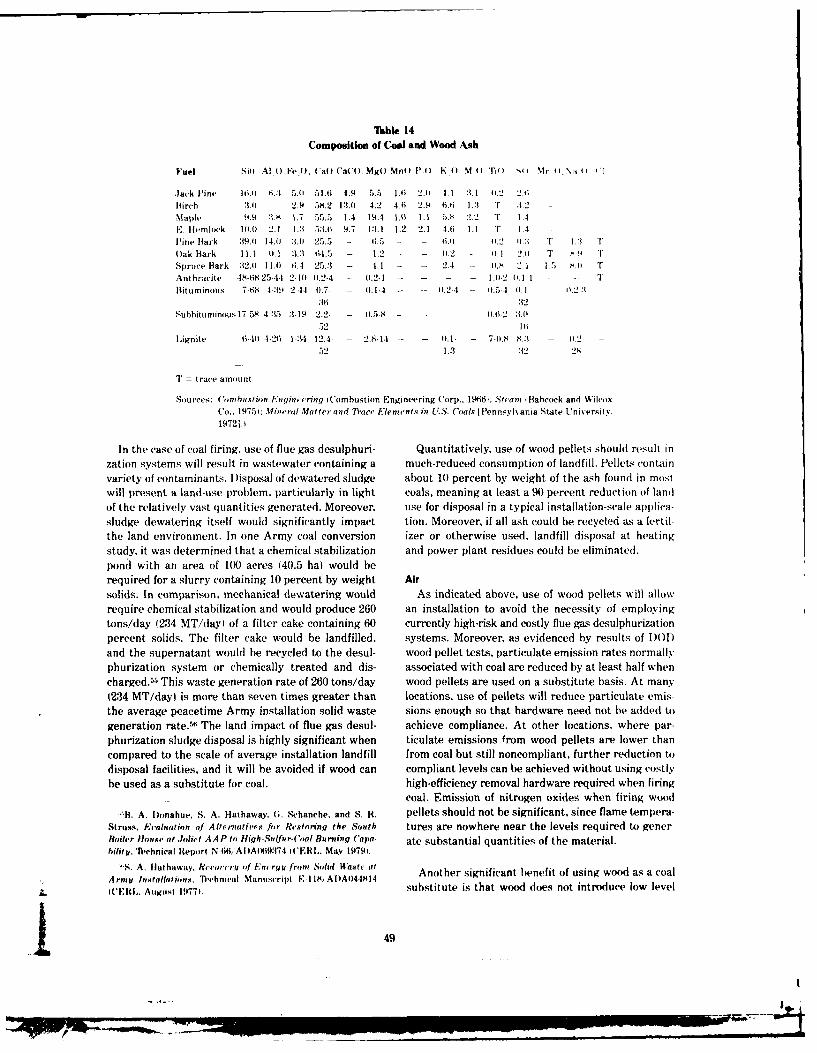
Iable 14Composition of Coal and Wood Ash
Fuel Si4 Al 0 FeU I'a) CaC(, MgO Mn) P 4) K 0 M) Ti , Mn .\A 0
Jack Pine fi.tl 6.3 5.0 51. 6 4.9 5.5 1.6i 2.0 4A 1. 1 4.2 2.6
Birch 3.04 2.9 58.2 13.0 4.2 4.6 2.9 6.1 :1. T 3.2 -
Maple 44.9 t,.K 1.7 5 ..5 1.4 19.4 I.M 1.1 5. 2.2 T 1.1E. temlock 10.0 2.1 L3 5.i 9.7 1:1.1 1.2 2.1 4.6 1.1 T 1.4Pine Bark 39. 14.0 3.0 25.5 - 6.5 -- - 6.0 - 0.2 1 T 1.3 T
Oak Bark 11.1 1).1 3., 64.5 - 1.2 - .2 1 .1 2' T .9 ' TSpruce Bark 32.0 11.0 6.4 25.3 - 1.1 - - 2.4 - ).- 2.1 1.5 S."' TAnthracite 48-68, 25-44 2-10 0.2-4 - 0.2-1 - - I.0.2 0.1 1 - , T
Bituminous 7-68 4-:14 244 0.7- - (.1-4 - - 0.2-4 1.5-4 0.1 0,2:1:16 :32
Subbituminous 17-58 4-:5 3-19 2.2- - .5-S - - -. 2 :i -
52 ;(Lignite 6-404 N-2 1-:4 12.4- - 2.8-14 - - 40.1- - 7-0.S N.3 0.2
52 1.3 :32 28
T = trace amount
Sources: Comhustion Enginp cring ('ombustion Engineering Corp., 19161: Stearn iBabcock and WilcoxCo.. 19751: Milrncral Mattcrand Traci, Elements in U.S. Coals [Pennsylvania State UTniversitY.19721.
In the case of coal firing, use of flue gas desulphuri- Quantitatively, use of wood pellets should result in
zation systems will result in wastewater containing a much-reduced consumption of landfill. Pellet, containvariety of contaminants. Disposal of dewatered sludge about 10 percent by weight of the ash found in most
will present a land-use problem, particularly in light coals, meaning at least a 90 percent reduction of landof the relatively vast quantities generated. Moreover, use for disposal in a typical installation-scale applica-sludge dewatering itself would significantly impact tion. Moreover, if all ash could be recycled as a fertil-
the land environment. In one Army coal conversion izer or otherwise used, landfill disposal at heating
study, it was determined that a chemical stabilization and power plant residues could be eliminated.pond with an area of 100 acres (40.5 ha) would be
required for a slurry containing 10 percent by weight Airsolids. In comparison, mechanical dewatering would As indicated above, use of wood pellets will allow
require chemical stabilization and would produce 260 an installation to avoid the necessity of employingtons/day (234 MT/dayl of a filter cake containing 60 currently high-risk and costly flue gas desulphurization
percent solids. The filter cake would be landfilled, systems. Moreover, as evidenced by results of )ODand the supernatant would be recycled to the desul- wood pellet tests, particulate emission rates normally
phurization system or chemically treated and dis- associated with coal are reduced by at least half when
charged.5. This waste generation rate of 260 tons/day wood pellets are used on a substitute basis. At many(234 MT/day) is more than seven times greater than locations, use of pellets will reduce particulate emis-
the average peacetime Army installation solid waste sions enough so that hardware need not be added to
generation rate. 56 The land impact of flue gas desul- achieve compliance. At other locations, where par-phurization sludge disposal is highly significant when ticulate emissions from wood pellets are lower thancompared to the scale of average installation landfill from coal but still noncompliant, further reduction todisposal facilities, and it will be avoided if wood can compliant levels can be achieved without using costlybe used as a substitute for coal. high-efficiency removal hardware required when firing
coal. Emission of nitrogen oxides when firing wood
B. A. Ionahue, S. A. Hathaway. G. Schanche. and S. R. pellets should not be significant, since flame tempera-Struss. Evaluation of Alternatives fir Restoring the South tures are nowhere near the levels required to gener-Boiler louse at Joliet AAP to Htigh-Sulfur-C(oal Burning Capa- ate substantial quantities of the material.bilitt. Te1chnical Report N.166/AI)AI419374 (ERL. May 19791.
-S. A. Hathaway. Revorcri of lEncrqunt Sod Waste (it"t-"n,. Al Italaway. Rflcchat', ., anucript ,m olid asat Another significant benefit of using wood as a coalA rmyt Installat ions. "l1,ehnical Manuscript E I IS, AD)A044814
L IIIL. August 19771. substitute is that wood does not introduce low level
49
I -
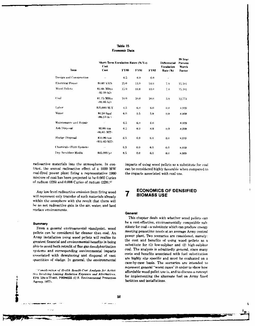
Tble 15Economic Data
20-'earShort-Term Fscalation Rates |%/Yr) l)iferential Present
Unit Escalation WorthItem Cost FY8O FY81 FY82 Rate f%) Factor
l)esign and Construction - 6.5 6.0 6.0 -
Electrical Power $0.03 kWh 15.o 14.0 14.1 7.)) 15,1)1
Wood Pellets $2.60,, M Btu 15.) 14.0 14.0 7.) 15. l) l1$2.46/kJ
Coal $1.75/MBtu 10.0 1).0 10.0 ,.1) 12.774i$1.66/kJ)
Labor $25,00/M-Y ti.5 6.) 6.) 0.0 8.939
Water $0.50/kgal 6.0 5.5 5.0) ).0) 8.939
1$0.13/m )
Maintenance and Repair - 6.5 6.) 6.) 8.939
Ash lislsal $6.0), ton 6.5 6.0 6.0 0.) 8.939($6.61, MT)
Sludge Disposal $10.00/ton 6.5 6.0 6.0 0.)) 8.939$11.02/MT)
Chemicals FGI) System) - 6.5 6.0 6.0 (.0 8.939
Dry Scrubber Media $15.0(X)/yr 6.5 6.) 6.0 0.0 8.939
radioactive materials into the atmosphere. In con- impacts of using wood pellets as a substitute for coaltrast, the annual radioactive effect of a 1000 MW can be considered highly favorable when compared tocoal-fired power plant firing a representative 1980 the impacts associated with coal use.mixture of coal has been projected to be 0.002 Curiesof radium (226) and 0.006 Curies of radium (228).57
ECONOMICS OF DENSIFIEDAny low-level radioactive emission from firing wood 7 COOM IS SE
will represent only transfer of such materials already 7within the ecosphere with the result that there willbe no net radioactive gain in the air, water, and landsurface environments.
GeneralThis chapter deals with whether wood pellets can
Summary be a cost-effective, environmentally compatible sub-From a general environmental standpoint, wood stitute for coal-a substitute which can produce energy
pellets can he considered far cleaner than coal. An meeting peacetime needs at an average Army centralArmy installation using wood pellets will realize its power plant. Two scenarios are considered, namely:greatest financial and environmental benefits in being the cost and benefits of using wood pellets as aable to avoid b ath retrofit of flue gas desulphurization substitute for (1) low-sulphur and (2) high-sulphursystems and corresponding environmental impacts coal. The analysis is admittedly general, since many
costs and benefits associated with fuel substitutionassociated with dewatering and disposal of vasthquantitie~s of sludge. In general, the environmental are highly site specific and must be evaluated on a
case-by-case basis. The scenarios are intended torepresent general "worst cases" in order to show how
('onsid,'roion of Ifealth Benefif-Cosf Analysis for Activi- affordable wood pellet use is, and to discuss a concepttirs In'oving Ionizing Radiation Exposur- and Alternatives.EPA 520/4-77403. PB286555 (U.S. Environmental Protection for implementing the alternate fuel on Army fixedAgency. 19771. facilities and installations.
50
Economic Data and Assumptions Assumptions commonly underlying the folloing
Tble 15 provides economic data used in evaluating analyses in'lude a system startup of the first day ofeach of the two fuel-substitution scenarios. Unit costs FY83 and a 20-year system life. Operation of allshown are average costs for each line item at the end systems was assumed to be an P..I, annual meanof FY79. Short-term and hog-term differential escala- peacetime load with an availallity of 0.85. includingtion rates are the same as applied elsewhere in similar scheduled and unforeseen outage. It was also assumedfuel-substitution analvse . , The 20-year. present- that within the 20-year life there would be no majorworth factor was computed using the following equation: cyclic repair or replacement of equipment. Finally in
[Eq 8] the case of using wood pellets as a substitute primary211 fuel in each of the two scenarios, application of the
PWF z [ 1 + I - i n I I + I -- dry granular media scrubber I)GMSI was assumed1 : +I +to be sufficient to reduce particulate emissions to
where PWF = 20-year present worth factor within compliant levels. Currently, 12 D(;MS systemsare in operation throughout the country and a reent
I = discount rate (=0.10) study of SCS Engineers for the Army pointed to its
i = long-term fractional differential applicability for reducing particulate emissions from
escalation rate installation-scale wood-fired boilers.,;" While theDGMS might not have enough particulate removal
n = integer year of economic life. efficiency to be effective when used on extremely
Several assumptions underlie the data in Table 15. noncompliant systems, it appears to achieve compli-
First, the cost of wood pellets is somewhat low but ance successfully when unabated particulate emis-
within the range of prices paid for such material to sions are close to compliant levels, as is the case with
support DOD tests. This cost reflects an assumed wood pellet firing.
local supply, so that transportation distances are min-imal. To reflect a "worst case" analysis, the escalationrates assigned to wood pellets are the same as those Substituting Wood Pellets for Sulphur-Compliant Coalgiven to electrical power. This assumption was also In this scenario, a 40 MBtu/hr (12 MWti powerbased on the fact that power is a major cost associated boiler is firing low-sulphur coal. The plant complieswith pellet production. Second, labor costs are assumed with emission guidelines for sulphur and nitrogento be $25,000/man-year, including benefits, and are to oxides but none with particulate emission guidelines.he taken as the total cost of an employee to his/her Th reduce emission of particulate matter, the installa-employer. While a supervisor will cost more than a tion considers the following two alternatives: I Ilaborer in an average work crew, a single cost was retrofit Teflon-media baghouse to the plant, or 121 fireassumed here to represent a rough average cost. substitute wood pellets and retrofit a )(GMS forThird. ash disposal costs are for bottom ash and fly particulate pollution abatement. It is assumed thatash in a dry state taken to an installation landfill for whichever alternative is selected, startup will le ondisposal. Costs of sludge disposal are higher and reflect the first day of FY83.the average cost of dewatering and solids disposal.
Finally, chemicals are given as an annual cost andwere estimated for a limestone scrubbing system For the first alternative (baghouse) the total turnkeyrequiring 6000 tons/yr (10,800 MT/yrI of materials first cost is $2,900,000 in FY83 dollars. The present-for a boiler rated 40 MBtu/hr (12 MWt. Estimated worth, annual-cost analysis in Table 16 indicates thatmaterial cost was on the order of $20,000/ton ($21.98/ the first cost is about 32 percent of the total, present-MTL. ', worth, annual cost of $9,138,400 (FY83 dollars',
Excluding fuel, the analysis shows that the majorannual costs are power, labor, and bag replacement.
'S. A. Hathaway. A. N. (ollishaw, and l. S. Lin, Reetwery '~ Baghouse costs shown in Tofle 16 were estimatedWnst, Ennrqy at Na-at Submarine linw, New London, Con-mn'eti'et. "'ehnieal Report E1 1:8 1 NaVdI Facilities EngineeringCommand [NAVFA('l. November 19781; Rerised Energy Con-scat ion Investment P'rogram Gu~idance iA. April 19771. 1"'B. West and J. Woodyard. Assessment of Dry (ranulor
'S. A. Hathaway. M. Tseng, and .). S. Lin. Project )eve op- Media Scruhbers for Ahatcment of Particulate "missions roinmeit (;uidulinas for (onvertinq Army Installations to ('oaf Stationary Point Combustion Soures on Army Fixed Paeihtis
('s,. Interim Report E 14$ ADA068025 ('ERL. March 1979). and Installations ISCS Engineers. Long Reach. ('A, 1979.
51
I'.,
p --. t,
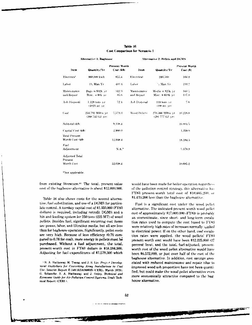
Tlible 16Cost Comparison for Scenario I
Alternativ- I: uaghouse Alternative 2: Pellets and )(,M,
Present Worth P'resent WorthItem Quantit /Yr (ost (k$i Item Quantit.y/Yr Cost ((
Elect rica' 468,(X kwh 655.4 Elect riea) 246,56,0 166.9
Labor I I., Man Yr 4(18 4 Labor - Man Yr 1:3.7
Mainutnance flags u $32k yr :342.3 Maintenanc' Media a $15k yr 161.5andt Repair Misc. (a $8k yr 85.f; and IG-pair Misc. a $10k yr II7(I
Ash Disposal 1.128 tons ,r 72.4 Ah )ispoal 119 tons yr .11023 mt yr I 108 Mt .. r
(al 254.732 Mlitu yr 7.5 %:", )\,d Pellt.- 27,,.)66 IIt yr 1.r22s. Si2t,8 742 ( yri (291 777 (;J %r,
Subtotal tk$i 9l,: .4 1V..5
Capital Cost 11S) 2 .o . :150.0
Total PresentWorth Cost lkS) 12.038.4 IN.184.5
FuelAdjustment N.A." -7.579.
Adjusted TtalPresentWorth Cost 12,038.4 10.605.2
*Not applicable.
from existing literature."' The total, preent-value would have been made for boiler operation rc'ardhe-s,cost of the baghoust, alternative is about $12,I)0,(X). of the pollution control strategy. this alternati't ha,
FY83 present-worth total cost of $10.605,200. or
Table 16 also shows costs for the second alterna- $1,433,2M() less than the baghouse alternative.
tive, fuel substitution, and use of a l)GMS for particu- Fuel is a significant cost under the wood pvlltlate control. A turnkey capital cost of $1,350,000 (FY83 alternative. The indicated present-worth wood pelletdollars) is required, including retrofit DGMS and a cost of approximately $17,(XX).J00 FY831 is probably'bin and feeding system for 250 tons 1225 MT) of wood an overestimate, since short- and long-term escalapellets. Besides fuel, significant recurring cost items tion rates used to compute the cost based to FY83are power, labor, and filtration media, but all are less were relatively high rates of increases normally .ppliedthan for baghouse operation. Significantly, pellet costs to electrical power. If on the other hand. coal escala-are very high. Because of less efficiency (0.70 com- tion rates were applied, the wood pellets' FY83pared to 0.76 for coal), more energy in pellets must be present-worth cost would have been $12,225,800 127purchased. Without a fuel adjustment, the total, percent lessl, and the total, fuel-adjusted, present-present-worth cost in FY83 dollars is $18,184,500. worth cost of the wood pellet alternative would haveAdjusting for fuel expenditures of $7,579,300 which been $6,572,000, or just over half of the cost of thk-
baghouse alternative. In addition, cost savings asso-S. A. Hathaway. M. Tseng. and J. S. ,in. Projc,.- Develop- ciated with reduced maintenance and repair tdue to
merit Guidelines for Converting Army Installations to Coal improved wood ash properties) have not been quanti-Use, Interim Report E-148/ADA068O25 WCERL. March 1979): fied, but could make the wood pellet alternative even(;. Schanche. S. A. Hathaway. and J. Oxley, Technical andEconomic Guide for Air Pollution Control Systems. Draft Tech- more economically attractive compared to the bag-nical Repxort (WERI 1. house alternative.
52
a' "
R . . ..-. _. ,.,.

Takble 17Cost Comparison for Scenario 2
Alternatike I: Fl() Alternative 2: Pellets and DGMS
present Worth Present WorthItem Quantiti/Yr Cost Ik$I Item Quantit'./1r Cost (k1S
Electrical 3,770.00)4 2,552.6 Elect rical 246,560 166 9
ILabor V- %Ian Ye'ars 1.2034 Labor I.. Man Year 137
Maintenance 4'<. of Capital Maintenance Media (a $15k Y r I 1)).5andt Repair Cost of $3.5(00k 1.497.5 and Repair Misc. (a $10k yr 1 7.4
Sludge 1)isposal 8,00)O tons 855.7 Ash I)isisal 119 tons yr 7.1;17256 MT) 1108 MT yr
Water 20.00 kgal yr 117.01 Wood Pellets 276.56t Mt: vr 16.228x175 700 myrl 291 777 (;J Yr
Limestini. 6,000 tons 1,283.615442 MT)
Chemicals 10 Tons 3.7
19.1 NMT
(oal 280.205 MM; a 8.337.2
1295 G17 T;JF
Subtotal ik$ 15,840).7 16,804.5
Capital (Cost (k$) 3.5M54.0 1,350.0
flital PresentWorth (ost 1k$1 19.340.7 1. 184.5
Fuel Adjustment - - 7.579.:
Adjusted TtalPresent WorthCost 1SkI 19.340.7 10.611.5.2
Substituting Wood Pellets cost analysis in Table 17 indicates that the first cost isfor Sulphur-Noncompliant Coal about 22 percent of the present-worth annual cost of
In this scenario, a 40 MBtu/hr (40 MWtO power $15,840,700. Excluding fuel, the analysis shows thatboiler is firing coal having a sulphur content on the the major annual costs are power and maintenanceorder of 4 percent by weight. The plant complies with and repair, with those of limestone (scrubber sorbent)emission guidelines for nitrogen oxides but not with and labor being significant. Scrubber costs were esti-locally prevailing guidelines for sulphur oxides and mated according to the same procedure by which bag-particulate matter. The installation considers two alter- house costs were obtained in the above discussion.natives to bring air pollutant emissions within com- The total present-worth cost of the FGD alternativepliante: (I) retrofitting a flue gas desulphurization is approximately $19,300,000.(FGI) system which will simultaneously reduceparticulate emissions; and 121 firing substitute woodpellets and retrofitting a I)(;MS for particulate pollu- Table 17 also shows cost data for the wood pellet-
tion abatement. Startup of the chosen system will be I)GMS alternative, which are the same as tabulated
on the first day of FY8. earlier for the first scenario. In computing the present-worth costs for this alternative, a fuel cost adjustment
For the FGD system, the total turnkey first cost is of $7,579,300 was made. However, under the FGL)$3,500,00() in FY83 dollars. The present-worth, annual alternative, a present-worth expenditure of $8,337,2(X)
1 53
I
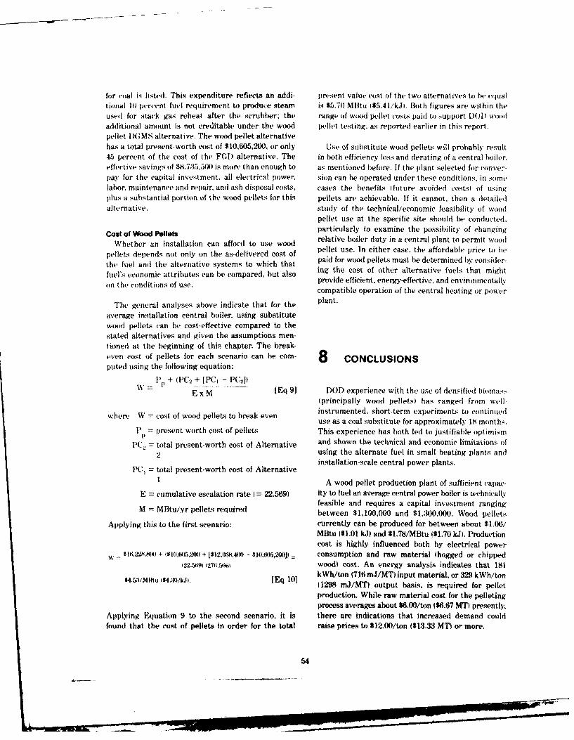
for coal is listed. This expenditure reflects an addi- present value cost of the two alternatives to be equaltional 1) percent fuel requirement to produce steam is $5.70 MBtu ($5,41/kJi. Both figures are within theused for stack gas reheat after the scrubber; the range of wood pellet costs paid to support [)O)D woodadditional amount is not creditable under the wood pellet testing, as reported earlier in this report.pellet-)GMS alternative. The wood pellet alternativehas a total present-worth cost of $10,605,200, or only Use of substitute wood pellets will probably result45 percent of the cost of the FGD alternative, The in both efficiency loss and derating of a central boiler.effective savings of $8,735,500 is more than enough to as mentioned before. If the plant selected for ronver-pay for the capital investment, all electrical power, sion can be operated under these conditions, in somelabor, maintenance and repair, and ash disposal costs, cases the benefits Ifuture avoided costsl of usingplus a substantial portion of the wood pellets for this pellets are achievable. If it cannot, then a detailedalternative, study of the technical/economic feasibility of wood
pellet use at the specific site should be conducted.
Cost of Wood Pellets particularly to examine the possibility of changing
Whether an installation can afford to use wood relative boiler duty in a central plant to permit wood
pellet. depends not only on the as-delivered cost of pellet use. In either case, the affordable price to hethe fuel and the alternative systems to which that paid for wood pellets must be determined by consider-fuel's economic attributes can be compared, hut also ing the cost of other alternative fuels that mightfuels teconoitriues cprovide efficient, energy-effective, and environmentally
compatible operation of the central heating or power
The general analyses above indicate that for the plant.
average installation central boiler, using substitutewood pellets can be cost-effective compared to thestated alternatives and given the assumptions men-tioned at the beginning of this chapter. The break-even cost of pellets for each scenario can be com- 8 CONCLUSIONSputed using the following equation:
W P + (PC2 + [PC1 - PC2 )E x M [Eq 9] DOD experience with the use of densified biomas,.
(principally wood pellets) has ranged from well-instrumented, short-term experimenL to continuedwhere W =cost of wood pellets to break evenuse as a coal substitute for approximately 18 months.
P = present worth cost of pellets This experience has both led to justifiable optimism
PC., = total present-worth cost of Alternative and shown the technical and economic limitations of
2 using the alternate fuel in small heating plants andinstallation-scale central power plants.
PC, = total present-worth cost of Alternative
1 A wood pellet production plant of sufficient capac-
E = cumulative escalation rate (= 22.569) ity to fuel an average central power boiler is technicallyfeasible and requires a capital investment ranging
M = MBtu/yr pellets required between $1,100,000 and $1.300,000. Wood pellets
Applying this to the first scenario: currently can be produced for between about $1.06/MBtu 1$1.01 kJ) and $1.78/MBtu ($1.70 kJ. Productioncost is highly influenced both by electrical power
w - $16,2m,8() + (81i,605,2M5) + [$12,(X,4(X) - $10M05,2001 consumption and raw material (hogged or chipped122.59 1271.r640 wood) cost. An energy analysis indicates that 181
$4.53/M~tu 4S4.30A/.,1. [Eq 101 kWh/ton (716 mJ/MT) input material, or 329 kWh/ton11298 mJ/MT) output basis, is required for pellet
production. While raw material cost for the pelletingprocess averages about $6.00/ton ($6.67 MT) presently,
Applying Equation 9 to the second scenario, it is there are indications that increased demand couldfound that the cost of pellets in order for the total raise prices to $12.00/ton ($13.33 MT) or more.
54
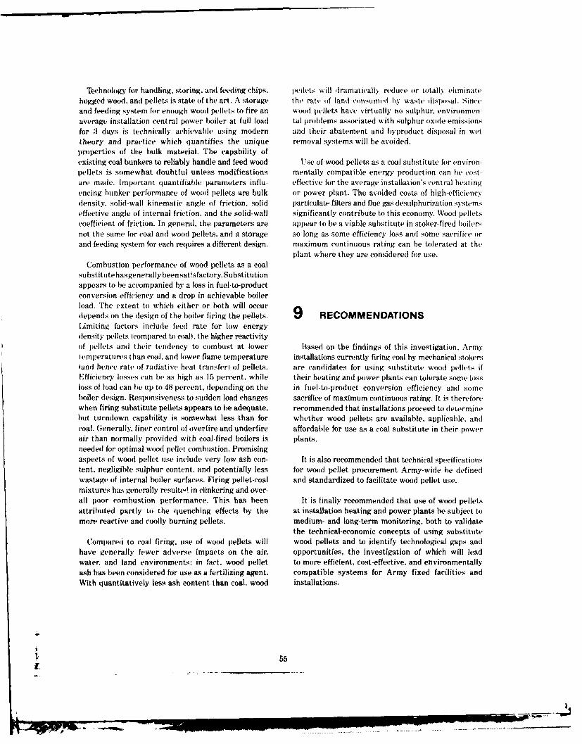
T'khnology for handling, storing, and feeding chips, pellet. will dramatically reduce or totally eliminatehogged wood, and pellets is state of the art. A storage the rate of land cvonsumed b'y waste disposal. Sinveand feeding system for enough wood pellets to fire an wood pellets have virtually no sulphur, environmen-average installation central power boiler at full load tal problems associated with sulphur oxide emissionsfor 3 days is technically achievable using modern and their abatement and byproduct disposal in wettheory and practice which quantifies the unique removal systems will be avoided.properties of the bulk material. The capability ofexisting coal bunkers to reliably handle and feed wood Use of wood pellets as a coal substitute for environ-pellets is somewhat doubtful unless modifications mentally compatible energy production can be cost-are made. Important quantifiable parameters influ- effective for the average installation's central heatingencing bunker performance of wood pellets are bulk or power plant. The avoided costs of high-efficiency(tensity, solid-wall kinematic angle of friction, solid particulate filters and flue gas desulphurization systemseffective angle of internal friction, and the solid-wall significantly contribute to this economy. Wood pelletscoefficient of friction. In general, the parameters are appear to be a viable substitute in stoker-fired boilersnot the same for coal and wood pellets, and a storage so long as some efficiency loss and some sacrifice orand feeding system for each requires a different design. maximum continuous rating can be tolerated at the
plant where they are considered for use.
Combustion performance of wood pellets as a coalsubstitute hasgenerally been satisfactory. Substitutionappears to be accompanied by a loss in fuel-to-productconversion efficiency and a drop in achievable boilerload. The extent to which either or both will occurdepends on the design of the boiler firing the pellets. 9 RECOMMENDATIONSLimiting factors include feed rate for low energy(tensity pellets (compared to coal), the higher reactivityof pellets and their tendency to combust at lower Based on the findings of this investigation. Armytemperatures than coal. and lower flame temperature installations currently firing coal by mechanical stokersIand hence rate of radiative heat transferi of pellets. are candidates for using substitute wood pellets ifEfficiency losses can be as high as 15 percent, while their heating and power plants can tolerate some lossloss of load can be up to 48 percent, depending on the in fuel-to-product conversion efficiency and someboiler design. Responsiveness to sudden load changes sacrifice of maximum continuous rating. It is thereforewhen firing substitute pellets appears to be adequate, recommended that installations proceed to determinebut turndown capability is somewhat less than for whether wood pellets are available, applicable, andcoal. Generally, finer control of overfire and underfire affordable for use as a coal substitute in their powerair than normally provided with coal-fired boilers is plants.needed for optimal wood pellet combustion. Promisingaspects of wood pellet use include very low ash con- It is also recommended that technical specificationstent, negligible sulphur content, and potentially less for wood pellet procurement Army-wide be definedwastage of internal boiler surfaces. Firing pellet-coal and standardized to facilitate wood pellet use.
mixtures has generally resulted in clinkering and over-all poor combustion performance. This has been It is finally recommended that use of wood pelletsattributed partly to the quenching effects by the at installation heating and power plants be subject tomore reactive and coolly burning pellets, medium- and long-term monitoring, both to validate
the technical-economic concepts of using substitute
Compared to coal firing. use of wood pellets will wood pellets and to identify technological gaps andhave generally fewer adverse impacts on the air, opportunities, the investigation of which will leadwater, and land environments; in fact. wood pellet to more efficient, cost-effective, and environmentallyash has been considered for use as a fertilizing agent. compatible systems for Army fixed facilities andWith quantitatively less ash content than coal, wood installations.
555
1.
- - - -
REFERENCES Hathaway. S. A. and .J. S. Lin, "Combustion Rates ofR)F," Proceedings of Third International C'onjfr.11110r on ,nc'ironrn/iitl Irobhis in th, Ertracti,,
Army Knerg? 'lan, At)A057987 Illeadquarters, Industrics W\Vright Corp.. )ayton, ()H. 19771.
)epartment of the Army i)AI. 1978.Hlathaway S. A. and .l. Lin. "'rnqroiim+.tri ..l ol
Arola, It., Wood Fu'ls-lb Io "'h Stuck p. !sis0 Soll % id ')us-lk'iiici F'uls and 'oal,
SFnergy and the Wood I'rducts Industry. Forest Technical Report E-149/AI)A067829 it .S. Army
Products Research Society, Madison, WI, 19741. (onstruction Engineering Research LaboratorvICERI.] March 1979).
Assessnment of the ('apability of Firing ('han Lou-IITU Gases in E'xisting Coal, Oil and Gas-FYred Hathaway. S. A.. M. Tseng, and J. S. Lin, l'ro/, et
Stearn (nerators, P13 248:328 (Combustion Engi- )' rctopmcnt (hidelincs Jor (onrerting A 1m!, In
neering Corp., 19751. stallations to Coal ('sc, Interim Report E-148AL)ADA8()25 (CERL. March 19791.
Atmospheric Emission and Performance Evaluationof Frajon Fuel Pellet (Alsid, Snowden and Associ- Hathaway, S. A. and R. J. Dealy, Technologyo lraua-
ates, Bellevue, WA, 1978). tion of Army-Scale Waste-to-Energy S.ystems, In-terim Report E-110/ADA042578 ICERL, July 19771.
Combustion Engineering (Combustion Engineering Hathaway, S. A., Recovery of Energy from olidCorp.. 19664. Waste at Army Installations, Technical Manuscript
Considerations in Selecting Wood as an Immediate E-118/ADA044814 (CERL, August 19771.
Source of Reliable and Economical Energy for Mili-tary Installations, FESA-TS-2061/ADA071791 Hiser, M., ed., Wood Energy (Ann Arbor Science,( U.S. Army Facilities Engineering Support Agency 19784.[FESA], 1978). Jenike, A., Flow of Solids in Bulk Handling Systcms!
Consideration of Health Benefit-Cost Analysis for Flow of Bulk Solids in Bins. Engineering Experi-
Activities Involving Ionizing Radiation Exposure ment Station Bulletin 64 (University of Utah, 19541.
and Alternatives, EPA 520/4-77-003, PB 286555 Jenike. A., Gravity Flow of Bulk Solids lUniversity of(U.S. Environmental Protection Agency, 1977). Utah, Engineering Experiment Station. 19614.
Curtis, A. B., Jr., "Wood for Energy: An Overview," Jenike. A., Storage and Flow of Solids, EngineeringF rest Products Utilization Bulletin (U.S. Forest Experiment Station Bulletin 123 (University ofService, Div of State and Private Forestry Areas, Utah, 1970).Southeast, September 1978).
Johanson, J., "Design for Flexibility in Storage andDonahue, B. A., S. A. Hathaway, G. Schanche, and Reclaim," Chemical Engineering, Vol 85, No. 24
S. R. Struss, Evaluation of Alternatives for Restor- (30 October 1978).ing the South Boiler House at Joliet AAP to High-Sulfur-Coal Burning Capability, Technical Report Johanson, J., "Know Your Material-How to PredictN-66/ADA069374 (CERL, May 1979). and Use the Properties of Bulk Solids," Chemical
Engineering, Vol 85, No. 24 (30 October 19781.Facilities Engineering Summary of Operations, FY77
(DA, Office of the Chief of Engineers, 1978). Koehler, A. The Properties and Uses of Wood iMcGraw-
Hill, 1924).General Catalogue 900 (Link Belt Corp, 1950).
Megonnell, W.. "Efficiency and Reliability of SulfurHathaway, S. A., A. N. Coilishaw, and J. S. Lin, Dioxide Scrubbers," Journal of the Air Pollution
Recovery of Waste Energy at Naval Submarine Control Association, Vol 28. No. 7 (July 1978).Base, New London, Connecticut, Technical ReportE-138 (Naval Facilities Engineering Command Meyer, A., Return to Wood as a Major Fuel Source[NAVFAC], November 1978). (Chase Manhattan Bank, 1978).
.[ 56
PIP -7

Preliminary Environmcntal Assussmcnt of Bionass Steam lBabcock and Wilcox, Inc.. 19751.Conversion to Syntheti FiIs, PB 289775 lBattelle-Columbus Laboratories, 1978. Stokvrs tor Industrial Boil'rs - Asscssincrnt T 7ichni-
cal, Economic. and En 'ironin'nt tors. IQl5?t6x.
Reactivity and Gasification ('haractcristics of Low IlBattelle-Columbus Laboratories. 19751.
Ranking Coals and Potentially Reducing WasteMaterials, PERC/RI-76/2 (Pittsburgh Energy Re- Study of Alternate Fuels, tHeating Plant t,r Ma.jolr
search Center. 1976). Support Afrva, THdent Submarin, Bas, BangorAnnex. Kcyport, Washington 11Bumstead-Woolford.
Reed, T. and B. Bryant, Densified Biomass: A New Co., 1978).
Ib'rm of Solid Fuel, SERI-35 Solar Energy Re-search Institute, 1978). Supplemental Wood Fuel Experi~ment I Hoard of i~uzhtand Power, Grand Haven, MI. 19781.
Revised Energy Conservation Investment Program Tillman, D. Wood as an Energy Rcsource iAcademicGuidance IDA, April 19771. Press, 19781.
Schanche, G., S. A. Hathaway, and J. Oxley, Technical Tuttle, K. and D. ,Junge, "'Combustion Mechanisms inand Economic Guide frAir Pollution Control Sys- Wood Fired Boilers," Journal of the Air Pollutiontems. Draft Thchnical Report (CERLI. Control Association, Vol 28, No. 7 (July 19781.
Shafizadeh, F. and W. DeGroot, "Thermal Analysis of West, B. and J. Woodyard, Assessment ofl)r!q (;ranuForest Fuels," Fuels and Energy from Renewable lar Media Scrubbers for Abatement of ParticulattResources (Academic Press, 19771. Emissions From Stationary Point Combustion
Sources on A rmy Fixed Facilities and InstallatinsSmith, M. and K. Stinson, Fuels and Combustion ISCS Engineers. Long Beach, CA, 19791.
(New York, 1952)Wilson, D. G., Handbook of Solid Waste Management
Solid Fu l Burners IPeabody Gordon-Piatt, Inc., 1979). IVan Nostrand-Reinhold, 1978).
Spurr, Stephen H., "Silviculture," Scientific AmeN- Wood Energy for Small Scale Power Production incan. Vol 240, No. 2 11979). North Carolina (Ultrasystems, Inc., 1978).
57
I)
- °'
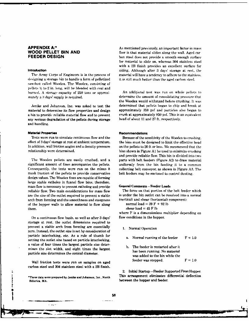
APPENDIX A:* As mentioned previously, an important factor in massWOOD PELLET BIN AND flow is that material slides along the wall. Aged car-FEEDER DESIGN bon steel does not provide a smooth enough surface
for material to slide on, whereas 304 stainless steelwith a 2B finish provides an excellent surface for
Introduction siding. Although after 3 days' storage at rest, theThe Army Corps of Engineers is in the process of material will have a tendency to adhere to the stainless,
designing a storage bin to handle a form of pelletized it is still much better than the aged carbon stel.sawdust called Woodex. The Woodex, consisting ofpellets 1/2 to 2 in. long, will be blended with coal andburned. A storage capacity of 250 tons or approxi- An additional test was run on whole pellets tomately a 3 days' supply is required, determine the amount of consolidating pressure that
the Woodex would withstand before crushing. It wasJenike and Johanson, Inc. was asked to test the determined that pellets began to chip and break at
material to determine its flow properties and design approximately 350 psf and particles also began toa bin to provide reliable material flow and to prevent crush at approximately 854) psf. This is an equivalentany serious degradation of the pellets during storage head of about 11 and 27 ft, respectively.and handling.
Material Properties RecommendationsTests were run to simulate continuous flow and the Because of the sensitivity of the Woodex to crushing,
effect of 3 days' storage at rest at ambient temperature. the bins must be designed to limit the effective headIn addition, wall friction angles and a density-pressure on the pellets to 20 ft or less. We recommend that therelationship were determined, bins shown in Figure Al be used to minimize crushing
and provide reliable flow. This bin is divided into twoThe Woodex pellets are easily crushed, and a parts with belt feeders (Figure A2) to draw material
significant amount of fines accompanies the pellets, uniformly from the bin feeding it to a commonConsequently, the tests were run on the minus 8 collecting belt conveyor, as shown in Figure A3. Themesh fraction of the pellets to provide conservative belt feeders may be enclosed to control dusting.design values. The Woodex fines are capable of forminglarge stable ratholes in funnel flow bins; therefore,mass flow is necessary to prevent ratholing and provide General Comments-Feeder Loadsreliable flow. Two main considerations for mass flow The force on that portion of the belt feeder whichare the size of the outlet required to prevent a stable is under the bin outlet can be resolved into a normalarch from forming and the smoothness and steepness (vertical) and shear (horizontal) component:of the hopper walls to allow material to flow along normal load = 39 F + 92 lbthem. shear load = 45 F lb
where F is a dimensionless multiplier depending onOn a continuous flow basis, as well as after 3 days' flow conditions in the hopper.
storage at rest, the outlet dimensions required toprevent a stable arch from forming are essentially 1. Normal Operationzero. Instead, the outlet size is set by consideration ofparticle interlocking, etc. As a rule of thumb forsetting the outlet size based on particle interlocking,a value of four times the largest particle size deter-mines the slot width, and eight times the largest he feederui r t ateritparticle size determines the conical diameter. has bee runnin Noimatewas added to the bin while the
Wall friction tests were run on samples on aged feeder was stopped. F 1.0
carbon steel and 304 stainless steel with a 2B finish.2. Initial Startup- Feeder Supported From Hopper.
*These data were prepared by Jenike and Johanson, Inc., North This arrangement eliminates differential deflectionBillerica, MA. between the hopper and feeder.
58
now-e
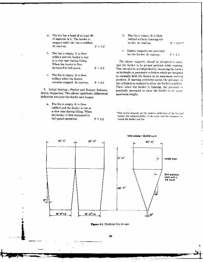
a. The bin has a head of at least 20 b. The bin is empty. It is thenof material in it. The feeder is refilled without running thestopped while the bin is refilled. feeder. At startup. 1" -- +At startup, F = 1.2
c. Elastic supports are providedh. The bin is empty. It is then for the feeder. At startup. F = I.5
refilled anti the feeder is runat a slow rate during filling. The elastic supports should be designed to mainWhen the feeder is first tain the feeder in its proper position while runningincreased to full-speed. F = 1.2 This can also be accomplished by mounting the feeder
on hydraulic or pneumatic cvlinders which art designe ic. The bin is empty. It is then to normally hold the feeder in its maximum verticalrefilled while the feeder position. If starting problems occur, the pressure inremains stopped. At startup. F = 2.5 the cylinders is reduced to allow the feeder to deflecl.
Then, when the feeder is running, the pressure i3. Initial Startup-Feeder and Hopper Indepen- gradually increased to raise the feeder to its ustildently Supported. This allows significant differential maximum height.deflection between the feeder and hopper.
a. The bin is empty. It is thenrefilled and the feeder is run ata slow rate during filling. When *This factor depends on the relative deflection of thc hin andthe feeder is first increased to feeder, the compressibility of the solid. and the clearan., I,,full speed operation, F = 1.2 tween the feeder and bin.
total volume" 18,000 cu. ft
W. 200 201-0. 20.- 0"
15'- O-" carbon steel
s i304 stainlesssteel with a
2B finish
19.
5.U __8' - V_
l5-O" I S. 0 *1 S
igure Al. Modular bin design.
...5 9
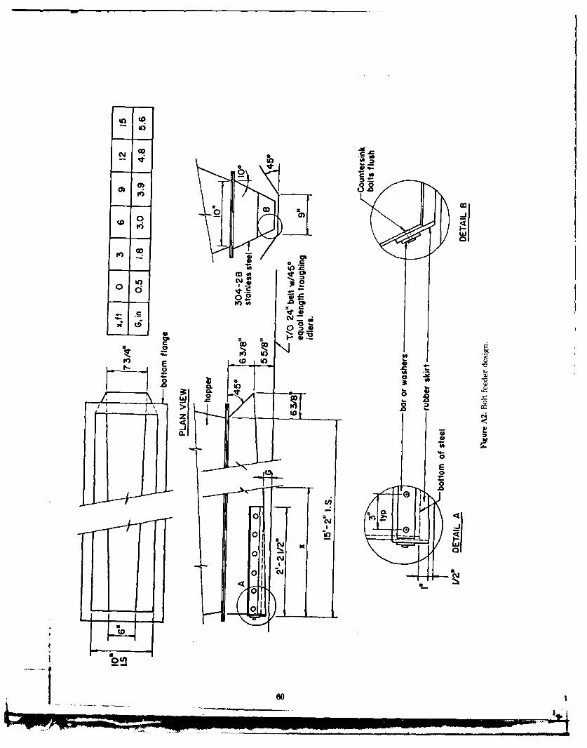
inIn
0c
co
0 0
%, 0
SAn
.93-
CL
060
z t
.
0.0E
Z
010
0 11CONN
60
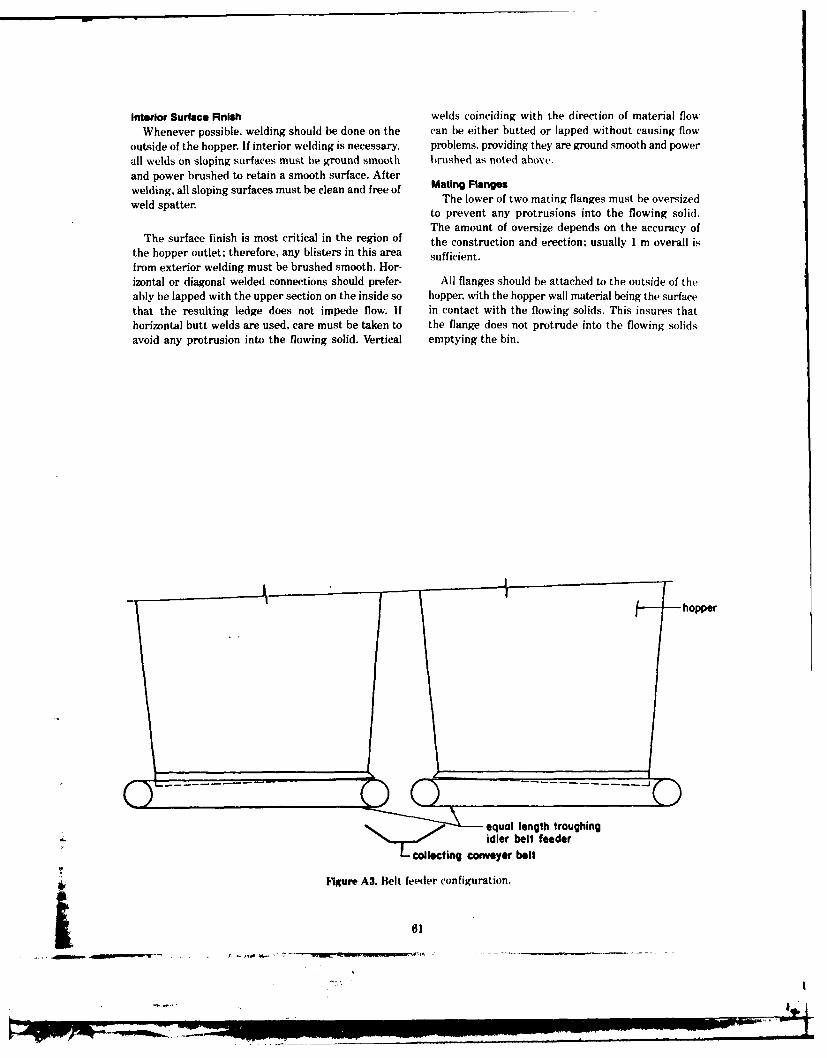
Interior Surface Finish welds coinciding with the direction of material flowWhenever possible, welding should be done on the can be either butted or lapped without causing flow
outside of the hopper. If interior welding is necessary, problems, providing they are ground smooth and powerall welds on sloping surfaces must be ground smooth brushed as noted above.and power brushed to retain a smooth surface. Afterwelding, all sloping surfaces must be clean and free of Mating Flangesweld spatter. The lower of two mating flanges must be oversized
to prevent any protrusions into the flowing solid.The amount of oversize depends on the accuracy of
The surface finish is most critical in the region of the construction and erection; usually 1 m overall isthe hopper outlet; therefore, any blisters in this area sufficient.from exterior welding must be brushed smooth. Hor-izontal or diagonal welded connections should prefer- All flanges should be attached to the outside of theably be lapped with the upper section on the inside so hopper, with the hopper wall material being the surfacethat the resulting ledge does not impede flow. If in contact with the flowing solids. This insures thathorizontal butt welds are used, care must be taken to the flange does not protrude into the flowing solidsavoid any protrusion into the flowing solid. Vertical emptying the bin.
hopper
equal length troughing'F~~ting idler belt feeder
"' oll~tlngconveyer belt
Figure A3. Belt feeder configuration.
61
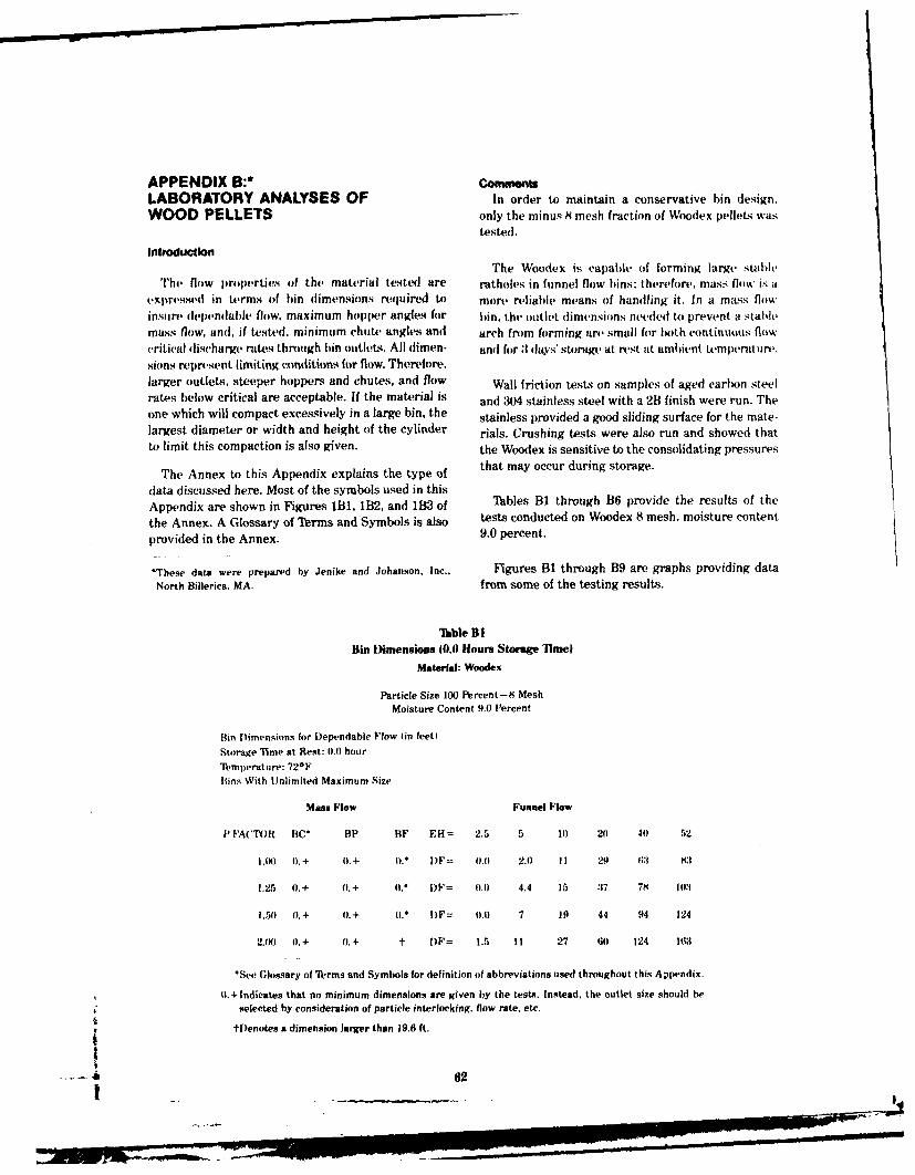
APPENDIX B:* con'mrsLABORATORY ANALYSES OF In order to maintain a conservative bin design,WOOD PELLETS only the minus 8 mesh fraction of Woodex pellets was
tested.
IntroduclonThe Woodex is capable of forming large stahh,
The flow pro)erties of the material tested are ratholes in funnel flow bins: therefore, mass flow is a
expressed in terms of bin dimensions required to more reliable means of handling it. In a mass flowinsure dependabh, flow, maximum hopper angles for bin, the outlet dimensions needed to prevent a stahlemass flow, ani, if tested, minimum chute angles and arch from forming are small for both continuous flow(ritical discharge rates through bin outlets. All dimen- and for :1 days' storage at rest at ambient temperature.sions reprsent limiting (oflditiflns for flow. Therefore.larger outlets, steeper hoppers and chutes, and flow Wall friction tests on samples of aged carbon steelrates below critical are acceptable. If the material is and 304 stainless steel with a 21 finish were run. Theone which will compact excessively in a large bin, the stainless provided a good sliding surface for the mate-largest diameter or width and height of the cylinder rials. Crushing tests were also run and showed that
to limit this compaction is also given, the Woodex is sensitive to the consolidating pressures
The Annex to this Appendix explains the type of that may occur during storage.
data discussed here. Most of the symbols used in thisAppendix are shown in Figures 1B1, 1B2, and 1133 of Thbles B1 through B6 provide the results of the
the Annex. A Glossary of Terms and Symbols is also tests conducted on Woodex 8 mesh, moisture content
provided in the Annex. 9.0 percent.
'These data were prepared by Jenike and Johanson. Inc., Figures BI through B9 are graphs providing data
North Billerica. MA. from some of the testing results.
Table B IBin l)imensions 10.O Hours Storage limel
Material: Woodex
Particle Size 100 Percent-8 MeshMoisture Content 9.0 Percent
Bin Dimensions for Dependable Flow (in feet IStorage Time at Rest: 0.0 hourTemperature: 720FBins With Unlimited Maximum Size
Mass Flow Funnel Flow
1'-FACTOR RC* BP BF EH= 2.5 5 10 20 40 52
1.0) 0. + 0.+ 0. I)F= 0.0 2.0 I1 29 6:1 M:3
1.25 0.+ 0.+ 0. )F= 0.0 4.4 15 :17 7N 103
1.50 0.+ 0.+ 0." D)F= 0.0 7 19 44 94 124
2.00 0.+ 0.+ 1" DF= 1.5 11 27 610 124 163
*See Glossary of Terms and Symbols for definition of abbreviations used throughout this Appendix.
4 0.+ Indicates that no minimum dimensions are given by the testa. Instead, the outlet size should beselected by consideration of particle interlocking, flow rate, etc.
tDenotes a dimension larger than 19.6 ft.
-4k 62
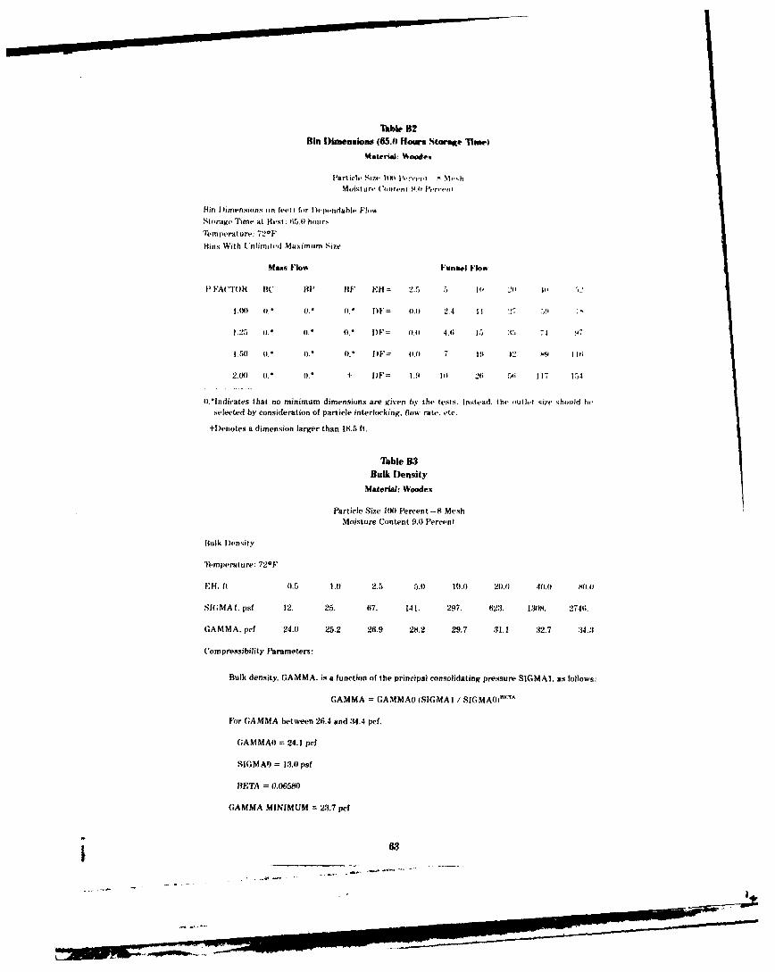
Tbk. B2Bin )imenaions (653.1 Hours Star"E hind)
Material: Woode,
MoIst tre (Contetn 0 9 0 r,F
Hin Dimensions tin feet i for Dlevendable Fl'i..Storage Time at Rest: 6.5.) hour.
'l-tmperature: 729F
Bins With Unlimited Maximum Size
MasS Flow Funnel Flow
PFA('Tt)R BC BP RF EH= 2.5 5 ' 2I _41
Io) 1). 0. 1 0. D F= 0. 0 2.4 1 27 7.9 T
1.25 0. t.* (. [)F= 1A 4.0 5 ;C" 74 97
I.5(1 .5 0. t.* lF 0.0 7 19 42 89 11l
20(8 0. o. 1- I)F= 1.9 10 26 .i 1 17 i7)
.*Indicates that no minimum dimensions are given by the tests. Instead. the outlet size should heselected by consideration of particle interlocking, flow rate. etc.
+I)enotes a dimension larger than 18.5 ft.
Tble B3Bulk Density
MaterIa: Woodex
Particle Size JIM Percent-8 MeshMoisture Content 9.0 Percent
Bulk Density
"l1-mperature: 720F
EU. ft 0.5 1.A) 2.5 5.0 10.0 20.0 40.0 M01
S (;MA 1. psf 12. 25. 67. 141. 297. 623. 1308. 2746.
GAMMA, pef 24.0 25.2 26.9 28.2 29.7 31.1 32.7 34.3
Compressibility Parameters:
Bulk density, GAMMA, is a function of the principal consolidating pressure SIGMAI, as follows:
GAMMA = GAMMAO (SIGMA / SIGMA0H sTA
For GAMMA between 26.4 and .34.4 pcf.
GAMMAO = 24.1 pet
SIGMAD) = 13.0 pat
BETA = 0.06580
GAMMA MINIMUM = 23.7 pef
263
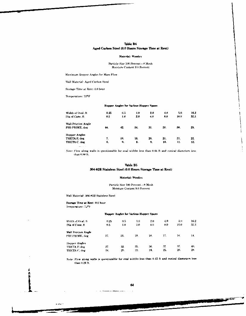
Table B4Aged Carbon Steel 10.0 Hours Storage Tlime at Rest)
Material: Woodex
Particle Size 100) Percent-8 MeshMoisture Content 9.o? Percent
Maximum floppter Angles for Mass Flow
Wall Material: Aged Carbon Steel
Storage Time at Rest: 0).0 hour
Temperature: 72*F
Hopper Angles for Various Hopper Spans
Width of Oval. ft 0.25 11.5 1.0 2.0 4.0 5.41 16.2Dia of Cone. ft 0.5 1.0) 2.0 4.41 8.0 101.0 32.3
Wall Friction AnglePHI-PRIME. deg 44. 42. 341. 31. 30). 30. 29.
Hopper AnglesTHETA-P. deg 7. 10. l8. 20. 21. 21. 22.
THETA-C. deg 0. 0. 6. 9. 10. II. 12.
Note: Flow along walls is questionable for oval widths less than 0.44 ft and conical diameters lessthan ((.8 It.
'Table B53044#2B Stainless Steel 10.0 Hours Storage Time at Rest)
Material: Woodex
Particle Size INK) Percent -8 MeshMoisture Content 9.0 Percent
Wall Material: :144-02H Stainless Steel
Storage 71me at Rest: 0.0 hourTemperature: 720I-
Hopper Angles for Various Hopper Spans
Width oft Oval. ft (1.125 0.5 1.0 2.0 4.0 5.0? 16.2lDia of C'one. ft 0.5 I.0 2.0 4.0 8.0 I0.0 32.3?
Wall Friction Anglel111 I 1N M E. deg 27. 21. 19. is. 17. 116. 14.
llopiter AnglesTit ETA' R deg 270. 312. :15. K6 :37. :17. 411.
TIIETA C. (if-i 14. 20. 22. 24. 25. 26. 2K.
Notw Flow along walls is questionable for oval widths less than (0.12 ft and conical diamete,, less
than ((.24 ft.-
134
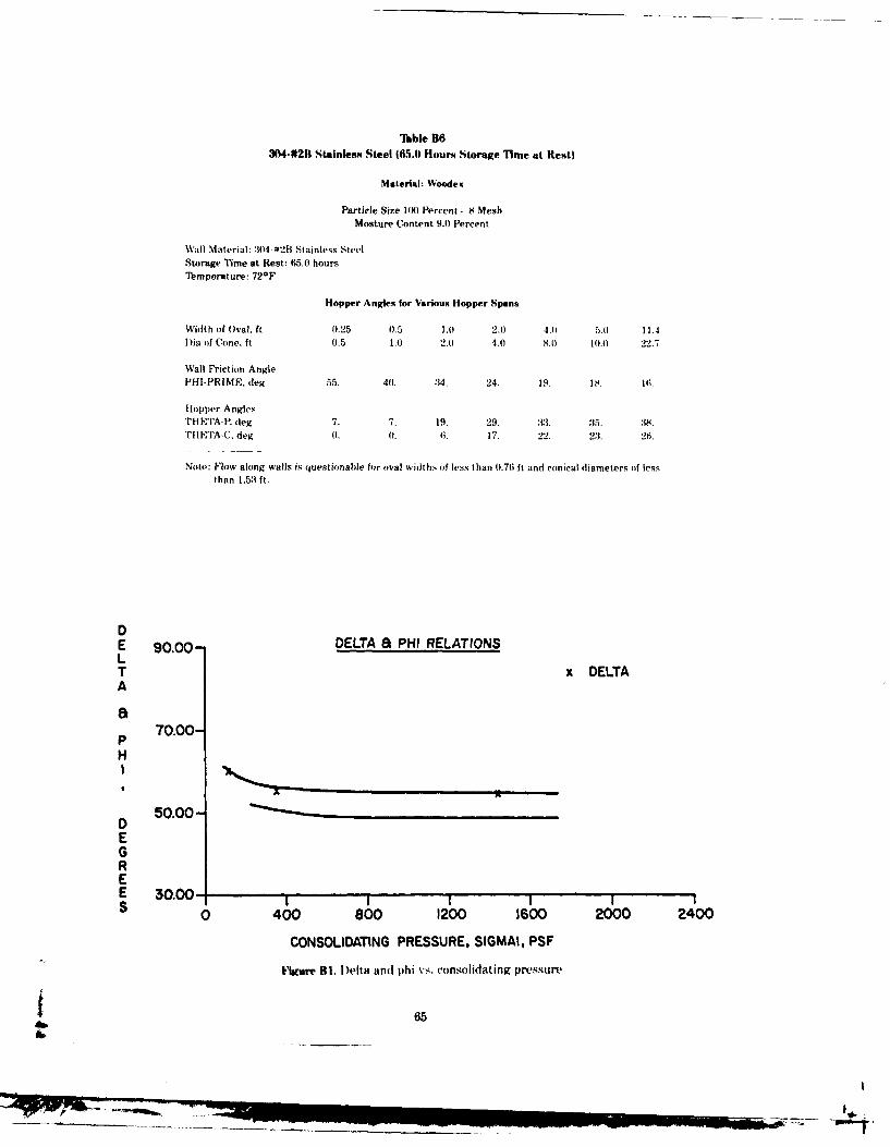
UIble B63044#2B Stainless Steel (65.0 Hours Storage Time at Rest)
Material: Woodex
Particle Size 100 Percent -8 MeshMosture Content 9.0 Percent
Wall Material: :104 #2B Stainless SteelStorage T1ime at Rest: 65.0 hoursMmperature: 72 0 F
Hopper Angles for Various Hopper Spans
Width of Oval, ft 0.25 0.5 1.0 2.0 4.0 5.0) 11.4D ia of Cone. ft 0.5 1.0 2.10 4.0) 8.0 10.0A 22.7
Wall Friction Anglef'HI.PRIME. deg 55. 40. 314. 24. 1s. is. 16.
Hopper AnglesTHETA-P. (leg 7. 7. 19. 29. 33. 35. :18.THETA-C. deg 0. 0. 6. 17. 22. 2:3. 26.
Note: Flow along walls is questionable for oval widths of less than 0.76 ft and conical diameters of lessthan 1.53 ft.
DE 90.00- DELTA a PHI RELATIONSLT x DELTAA
aP 70.00-H
IA
D 50.00-EGREE 30.00-S 0 400 800 1200 1600 2000 2400
CONSOLIDATING PRESSURE, SIGMAI, PSF
iure BI. Delta and phi vs. consolidating pressure~
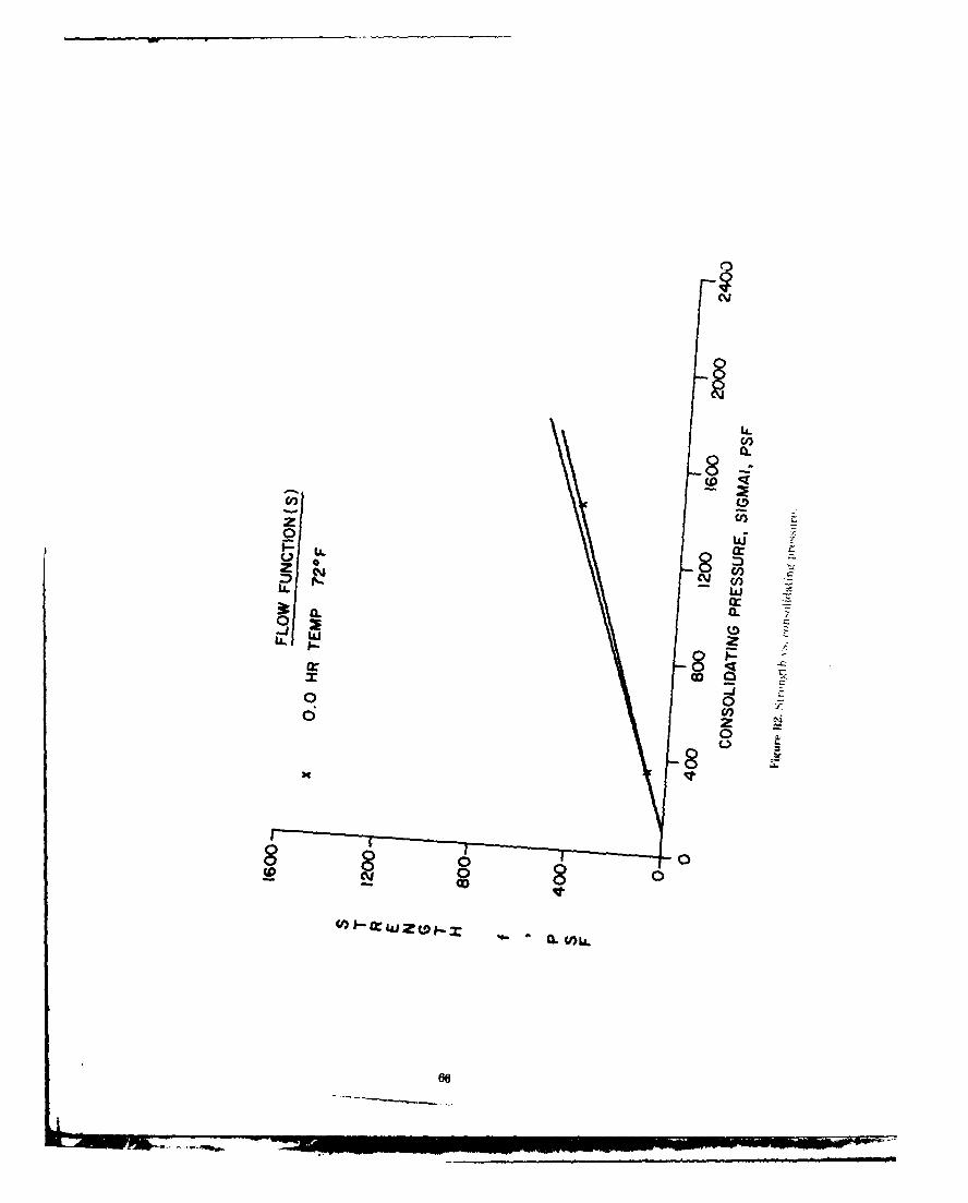
C,,
LL
LLLL;
0r0W
UJ 0
iL)
- 0
6
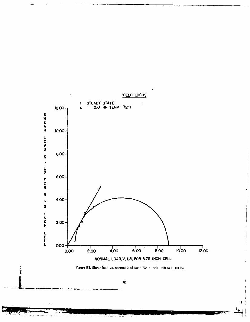
YIELD LOCUS
t STEADY STATE12.00- 0.0 HR TEMP 72OF
SHEAR 10.00-
L0AD
8.00-
L
F 6.00-0R
4.00-75
NC 2.00-H
CEL
0.00 2.00 4.00 6.00 8.00 10.00 12.00
NORMAL LOAD, V, LB, FOR 3.75 INCH CELL
Figure B13. Shear load vs. normal load for 3.75- in, cell (00N) to 12(M Ito.
67

YIELD LOCUS
t STEADY STATE30.00- x 0.0 HR TEMP 72*F
+ 65.0 HR TEMP 720 FSHEAR 25.00-
L0AD
S 20.00-
LB
F 15.00-0R
3* 10.00-
75
NC 5.00-H
CELL 0.00 1
0.00 5.00 10.00 15.00 20.00 25.00 30.00
NORMAL LOAD V, LB, FOR 3.75 INCH CELLFigure B4. Shear load vs. normal load for 3.75-in, cell 10ANI ta o.I00 Ihi.
p *1 -
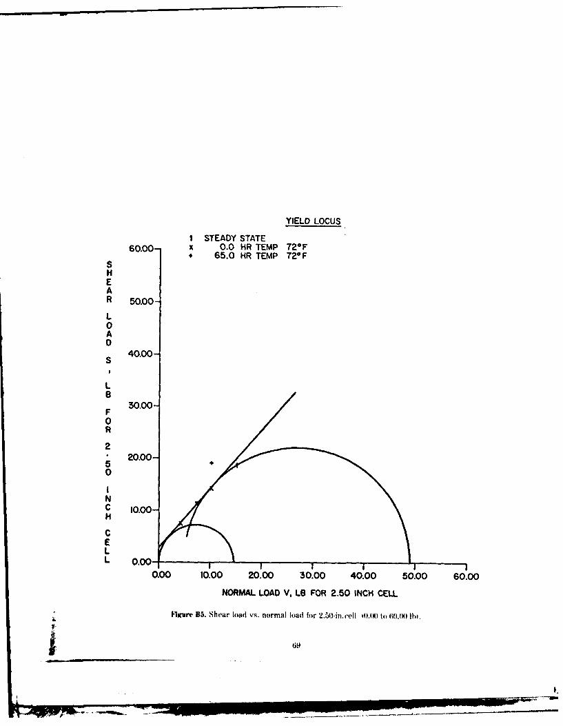
YIELD LOCUS
I STEADY STATE60.00- x 0.0 HR TEMP 72*F
. 65.0 HR TEMP 72*FSHEAR 50.00-
L0AD
S 40.00-
L
F 30.00-
0R
25 20.00-50
INC 10.00-H
CELL 0.00-
0.00 10.00 20.00 30.00 40.00 50.00 60.00
NORMAL LOAD V, LB FOR 2.50 INCH CELL
Figure B5. Shear load vs. normal load for 2.50-in.xell O.X) to tio.) IN.
p_ _9
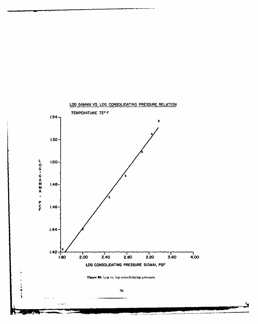
LOG GAMMA VS. LOG CONSOLIDATING PRESSURE RELATION
TEMPERATURE 720 F1.54-
1.52-
L 1.50-0G6
AM 1.48-MA
I xPC 1.46-F
1.44-
1.42- x
1.60 2.00 2.40 2.80 3.20 3.60 4.00
LOG CONSOLIDATING PRESSURE SIGMAI, PSF
V ure B6. Log vs. log consolidating pressure.
70
F1__..._._...._......_..
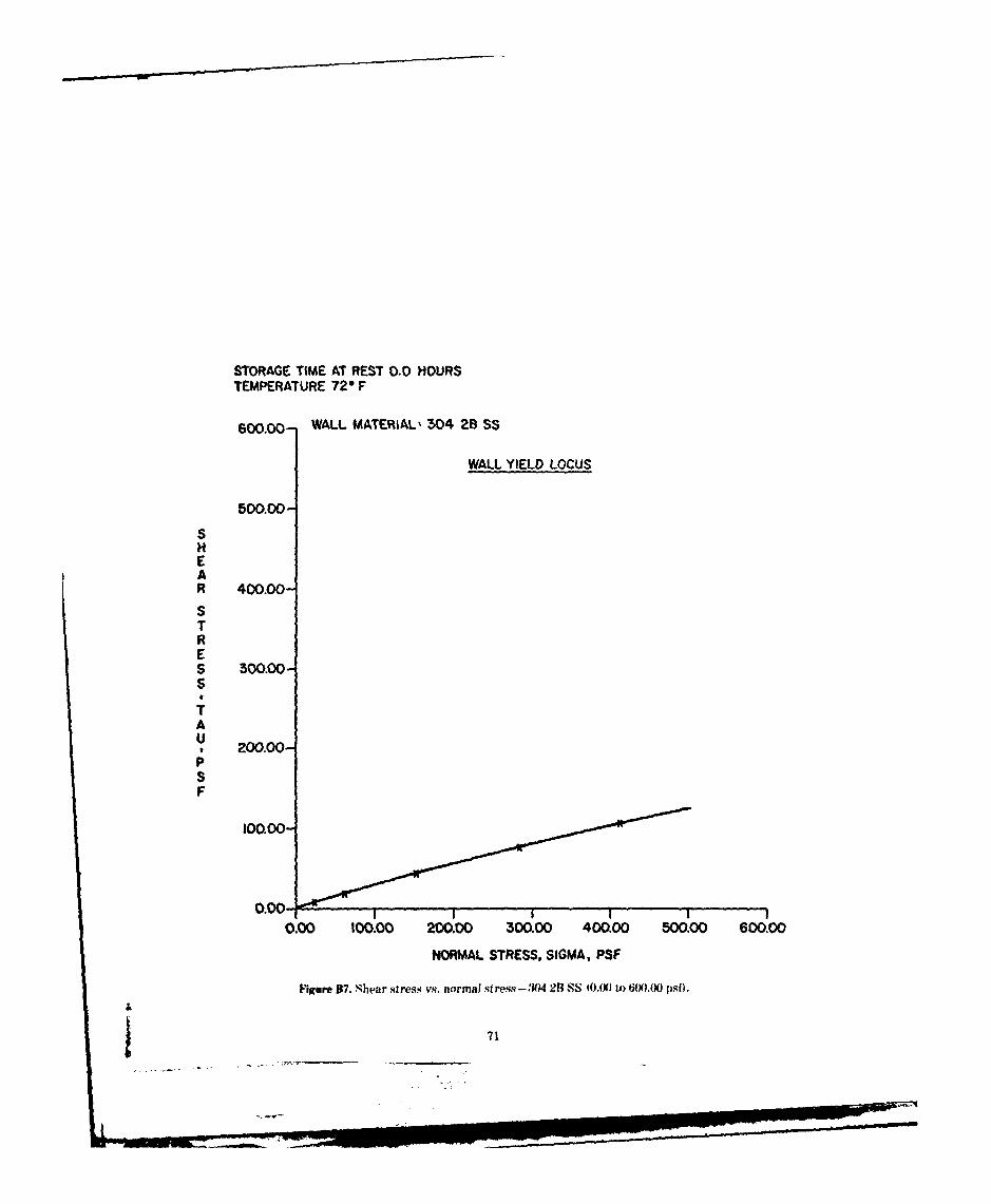
STORAGE TIME AT REST 0.0 HOURSTEMPERATURE 72 F
600.00- WALL MATERIAL' 504 2B SS
WALL YIELD LOCUS
500.00-
SHEAR 400.00-STRES 300.00-S
A
, 200.O0-PSF
100.00-
0.00 I
0.00 100.00 200.00 300.00 400.00 500.00 600.00
NORMAL STRESS, SIGMA, PSF
Ig'ure BT. Shear stress vs. normal stress-304 2B SS (O,(XJA i 6i .00 psfi.
71
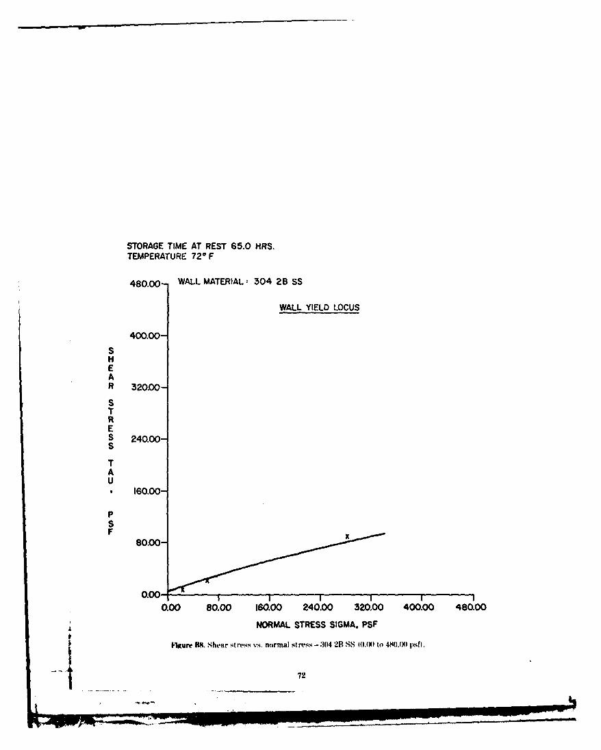
STORAGE TIME AT REST 65.0 HRS.TEMPERATURE 720 F
480.00- WALL MATERIAL: 304 2B SS
WALL YIELD LOCUS
400.00
SHEAR 320.00-
STRES 240.00-S
TAU
160.00-
PSF
80.00-
0.00 80.00 160.00 240.00 320.00 400.00 480.00
NORMAL STRESS SIGMA, PSF
I'gure M. Shear stress vs. normal stress-304 2B SS I.10 to 40.0) psfh.
72
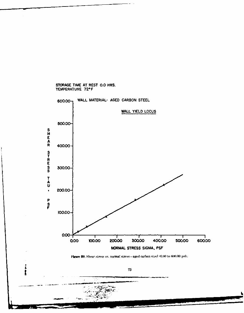
STORAGE TIME AT REST 0.0 HRS.
TEMPERATURE 720F
600O.00) WALL MATERIAL: AGED CARBON STEEL
WALL YIELD LOCUS
500.00-SHEAR 400.00-
STRES 300.00-S
TAU
200.00-
PSF
100.00-
0.00 100.00 200.00 300.00 400.00 500.00 600.00
NORMAL STRESS SIGMA, PSF
Igur W9. Shear stress vs. normal stress- aged carbon steel 10.(K) to 6OO.O) psf I.
73
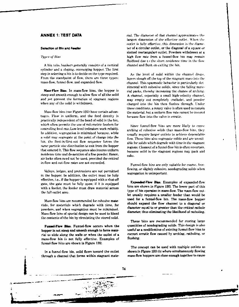
ANNEX 1: TEST DATA rial. The diameter of that channel ap)roximates thelargest dimension of the effective outlet. When theoutlet is fully effective, this dimension is the diame-
Selection of Bin and Feeder ter of a circular outlet, or the diagonal of a square orslotted lrectangular) outlet. Powders withdrawn at a
Thpes of Bin$ high flow rate from a funnel-flow bin may remainfluidized due t the short residence time in the flow
A bin (silo, bunker) generally consists of a vertical channel and flush on exiting the bin.cylinder and a sloping, converging hopper. The firststep in selecting a bin is to decide on the type required. As the level of solid within the channel drops.From the standpoint of flow, there are three types: layers slough off the top of the stagnant mass into themass-flow, funnel-flow, and expanded-flow, channel. This spasmodic behavior is particularly det-
rimental with cohesive solids, since the failing mate-Mass-Flow gins. In mass-flow bins, the hopper is rial packs, thereby increasing the chance of arching.
steep and smooth enough to allow flow of all the solid A channel, especially a small high-velocity channel.and yet prevent the formation of stagnant regions may empty out completely (rathole), and powderwhen any of the solid is withdrawn. charged into the bin then flushes through. Under
these conditions, a rotary valve is often used to containMass-flow bins Isee Figure 1131) have certain advan- the material, but a uniform flow rate cannot be insured
tages. Flow is uniform, and the feed density is because flow into the valve is erratic.practically independent of the head of solid in the bin,which often permits the use of volumetric feeders for Since funnel-flow bins are more likely to causecontrolling feed rate.Low-level indicators work reliablW. arching of cohesive solids than mass-flow bins, theyIn addition, segregation is minimized because, while usually require larger outleLs to achieve dependablea solid may segregate at the point of charge into the flow. These bins also segregate solids and are unsuit-bin. the first-in/first-out flow sequence forces the able for solids which degrade with time in the stagnantsame particle size distribution to exit from the hopper regions. Cleanout of a funnel-flow bin is often uncertain,that entered it. This flow sequence also insures uniform because solid in the stagnant regions may pack andresidence time and de-aeration of a fine powder. Hence, cake.air locks often need not be used, provided the criticalin-flow and out-flow rates are not exceeded. Funnel-flow bins are only suitable for coarse, free-
Valleys, ledges, and protrusions are not permitted flowing, or slightly cohesive, nondegrading solids when
in the hopper. In addition, the outlet must be fully segregation is unimportant.
effective, i.e., if the hopper is equipped with a shut-offgate, the gate must be fully open; if it is equipped Exanded-Flow Bins. Examples of expanded-flowwith a feeder, the feeder must draw material across bins are shown in Figure 1B3. The lower part of thisthe ulloutlt aea.type of bin operates in mass-flow. The mass-flow out-
let usually requires a smaller feeder than would be
Mass-flow bins, are recommended for cohesive mate- used for a funnel-flow bin. The mass-flow hopper
rials, for materials which degrade with time, for should expand the flow channel to a diagonal or
powders, and when segregation must be minimized, diameter equal to or greater than the critical rathole
Mass-flow bins of special design can be used to blend diameter, thus eliminating the likelihood of ratholing.
the contents of the bin by circulating the stored solid.These bins are recommended for storing large
Funnel-Flow Bins. Funnel-flow occurm when the quantities of nondegrading solids. This design is also
hopper is not steep and smooth enough to force mate- useful as a modification of existing funnel-flow bins torial to slide along the walls or when the outlet of a correct erratic flow caused by arching, ratholing, or
mass-flow bin is not fully effective. Examples of flushing.funnel-flow bins are shown in Figure 1B2.
The concept can be used with multiple outlets asIn a funnel-flow bin, solid flows toward the outlet shown in Figure 1B3 (b) where simultaneously flowing
through a channel that forms within stagnant mate- mass-flow hoppers are close enough together to cause
74
. ' .. , -.. ... .. -- - , . ,, " r ' -,-.
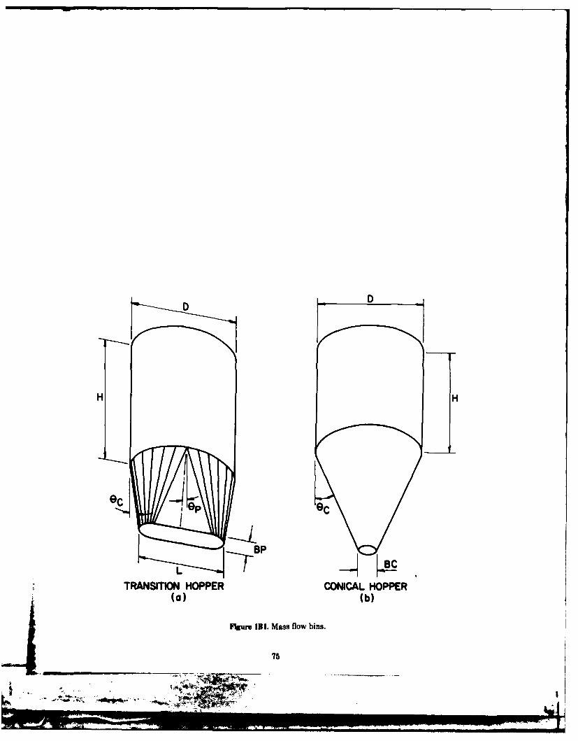
DD
eep
ep
TRANSI~ION HOPPER CONICAL HOPPER
(a) (b)
Figure 131. Mass flow bins.
75

0w -
r] H
B~F
NOT STEEP ENOUGH
Hum, 1112. Funnel flow bins.
76
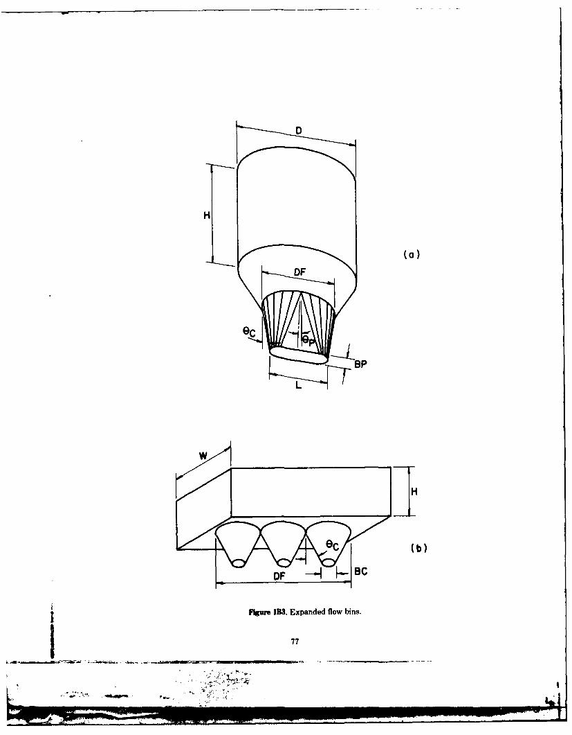
HD
HH
OC (b)
Figure 113. Expanded flow bins.
77
a combined flow channel that exceeds the critical Ifisc'ssion ofTcst Rc'port Iatr,
rathole diameter.In the following discussion, each Section of thi, ti st
Frcdcrs report is explained in general terms. Refer to FigurvsIB1, 1132, and 1133, where many of the symbill are
The specified outlet must be fully effective. If flow shown. The symbols and other terms used in the textfrom the bin is controlled by a feeder, the feeder must are defined in the Glossery of Terms and Symbols.be designed to draw uniformly through the entirecross-section of the outlet. a condition which fewcommercially available feeders satisfy. Sction I- B )ininwsions I'ir Dipindohbih 1"7t
This is especially important when feeding fine This section specifies the bin dimensions nicessarpowders from long slotted outlets fL> 3H. Thipical com- for dependable flow in both mass-flow and funrl-fhJkvmercial designs tend to draw material either from the for deedenon hass-flow and nebins. These dimensions have been calculated on the'front or the back of the slot, resulting in a high- basis of the solid's frictional and cohesive properties.velocity ('hannel having a (diameter of one to two In all cases, it is assumed that flow occurs only undertimes the width of the outlet. The powder may remain the action of gravity, i.e., without internal or externalfluidized within this channel and flush on exiting the assistance.bin.
Th limit high initial loads and starting torque, it is Generally, these dimensions are a function of the
essential that the feeder either he suspended from time the solid remains in storage at rest, moisture
the bin itself or supported on a flexible frame so as to content, temperature, size consist. and the over-
readily deflect with the bin as solid is added to it. pressure, if any, applied to it during storage. The
When the feeder is properly designed for uniform P-FACTORs are the ratios of applied compaction
flow, and when convergence of the hopper extends to pressure to the pressure resulting only from gravity
the feeder, the effective head EH) of solid on the flow. If there are no overpressures, the critical dimen-
feeder during flow in a mass flow bin will then be sions for P-FACTOR = 1.0 should be used. If thu
approximately P-FACTOR is greater than one, it is assumed thatoverpressures have been exerted on the solid during
Eli = BP for a transition hopper storage but are removed when the solid must flow.
EH = BC/2 for a conical hopper fEq 1131 Mass-flow bins have hopper walls which are smoothand steep enough to allow flow; hence, stable chan-nels within the material (ratholes) do not develop.Only two dimensions, both of which are shown inFigure 1B1, are specified: BC, the minimum outlet
Vibrating Equipment diameter for a conical hopper, and RP, the minimumwidth for a slotted or oval outlet. The length of the
Vibration has two effects: (1) it tends to break slot or oval should be at least three times its width.arches that obstruct flow, and (2) it packs the solid in. tagnant regions, thereby giving it greater strength. A funnel-flow bin is created whenever the hopper'lb allow for this packing, the recommended outlet walls are not steep and smooth enough to allow flow.dimensions at zero time at rest for a P-FACTOR Slotted outlets are recommended for these bins unless(described belowl of 1.5 may generally be used. the material flows freely. T prevent stable arches
from flowing, the width of the slot must be at leastVibrators are suitable for materials which are free- equal to BF. In a funnel-flow bin, the solid is held up
flowing uniler conditions of continuous flow but which at the walls and flows only within a circular channelcake and gain strength when stored at rest for hours whose diameter is approximately equal to the diameteror (lays. Hoppers for these materials should he or length of the effective outlet. If this flow channel
equipped with pads for mounting external vibrators. diameter is less than the critical rathole diameter I)F
Vibrating equipment is generally not recommended a stable rat hole is likely to form, and the live capacity
for fine powders and wet materials since they tend to of the bin will be essentially only that material which
pIack severely when vibrated, is in the flow channel above the outlet. Tb prevent
78
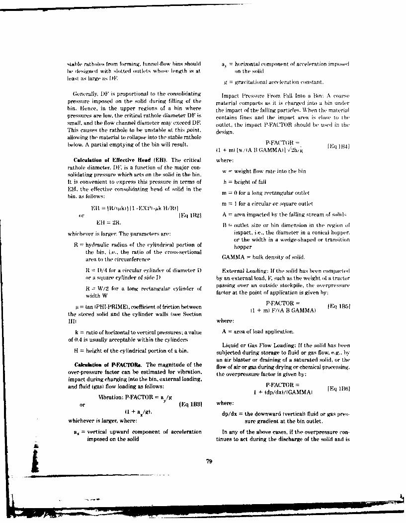
stable ratholes from forming, funnel-flow bins should a= horizontal component of acceleration imposedhe dlsigned with slotted outlets whose length is at on the solidleast as large as 1)F. g gravitational acceleration constant,
Generally, DF is proportional to the consolidating Impact Pressure From Fall Into a Bin: A coarsepressure imposed on the solid during filling of the material compacts as it is charged into a bin underbin. Hence, in the upper regions of a bin where the impact of the falling particles. When the materialpressures are low, the critical rathole diameter DF is contains fines and the impact area is close to thesmall, and the flow channel diameter may exceed DF. outlet, the impact P-FACTOR should be used in theThis causes the rathole to be unstable at this point, design.allowing the material to collapse into the stable ratholebelow. A partial emptying of the bin will result. P-FA'TOR I
1 + ml (w/A B GAMMAiI 1!2h/g [Eq 1B4]
Calculation of Effective Head (EH). The critical where:rathole diameter, DF, is a function of the major con-solidating pressure which acts on the solid in the bin. ight flow rate into the binIt is convenient to express this pressure in terms of h = height of fallEH, the effective consolidating head of solid in thebin, as follows: m 0 for a long rectangular outlet
I R ) II XP1k I/R)) m = 1 for a circular or square outlet
or [Eq 1B21 A = area impacted by the falling stream of solidsEll = 2R, B = outlet size or bin dimension in the region of
whichever is larger. The parameters are: impact, i.e., the diameter in a conical hopper.or the width in a wedge-shaped or transition
R = hydraulic radius of the cylindrical portion of hopperthe bin. i.e.. the ratio of the cross-sectionalarea to the circumference GAMMA = bulk density of solid.
R 1)/4 for a circular cylinder of diameter 1) External Loading: If the solid has been compactedor a square cylinder of side I) by an external load, F, such as the weight of a tractorR = W/2 for a long rectangular cylinder of passing over an outside stockpile, the overpressurewidth W factor at the point of application is given by:
= tan (PHI-PRIME), coefficient of friction between P-FACTOR = [Eq IB51the stored solid and the cylinder walls (see Section Q + m) F/IA B GAMMA)
III) where:
k = ratio of horizontal to vertical pressures; a value A = area of load application.of 0.4 is usually acceptable within the cylinders
Liquid or Gas Flow Loading: If the solid has beenH = height of the cylindrical portion of a bin. subjected during storage to fluid or gas flow. e.g.. by
an air blaster or draining of a saturated solid, or theCalculation of P-FACTORs. The magnitude of the flow of air or gas during drying or chemical processing,
over-pressure factor can be estimated for vibration, the overpressure factor is given by:impact during charging into the bin, external loading,and fluid (gas) flow loading as follows: P-FACTOR =E 1136)1 + Idp/dx)/(GAMMA) E Bl
Vibration: P-FACTOR = a /g
or [Eq IB31 where:01 + a/g), dp/dx = the downward verticalh fluid or gas pres-
whichever is larger, where: sure gradient at the bin outlet.
ax = vertical upward component of acceleration In any of the above cases, if the overpressure con-imposed on the solid tinues to act during the discharge of the solid and is
-. 79

pasitir'i downword, the overpressure factor need not between bulk density and consolidatme pressurt,be applied. If the downward pressure acts only during applies to densities greater than (,AMMA MINI.IV"M.
discharge, the dimensions given in Section I forP-FACT )R = I.0 may be reduced by dividing them Section III- Mim on oppi'r A nqh S .1hiss hbwlby the appropriate P-FACTOR.
When considering the effect of overpressure which A solid sliding on a bin wall encounters frictionalresistance proportional to the wall friction angle
acts on a solid during time of storage at rest. it is notPI-PRIME. This angle generally depends not only
necessary that the overpressure act during the entireon the roughness of the wall but also on the pressure
time at rest. Soon after overpressure has been applied, wi the ses o n the wall , or hardswale
a solid reaches the maximum densification associated wuice the frt an the olsurfaces. the friction angle decreases as the solids
with that overpressure. Hence, the critical outletcontact pressure increases. This pressure, which varies
dimensions will be essentially the same, whether the with position in the bin, is usually smallest at theoverpressure acts for a short time or continuously outlet.during the entire time at rest.
Limits on Bin Sizes. The bin dimensions in Tables THETA-Cand THETA-P are the recommended max-
BI and B2 apply to bins of unlimited maximum size. imum hopper slope angles. measured from the vertical.for conical and transition mass-flow hoppers. respec-
Some materials will compact in large bins, causing tively (see Figure 1B1. These values have been cal-large stable arches in the upper part of the hopper, culated from the friction tests twall yield locii and arewhile the lower portion may discharge without aprolem hich cale to mavy dhangerou a- tabulated for a series of widths of oval hoppers andproblem, which can lead to a very dangerous condi- diameters of conical hoppers. To minimize headroom.tion. When a large arch is broken high in the hopper, consider changing the slope of the hopper wall as ,.athe impulse of the falling material may cause structural function of position. For example, if a conical hopperdamage to the bin and possibly tear the hopper from is to be designed with an outlet diameter of I ft a dthe vertical bin section. the recommended THETA-C is 140 at a 1-ft diameter
anti 23 ° at 2-ft and larger diameters, use two coneOften, the upper limits on bin size occur only for g
sections. In the lower section, where the diametercompaction with time or for significant overpressure varies from 1 ft to 2 ft. use a hopper angle of 140.
conditions. If this is the case, the bin can be designed arie the I-t toa2ete, use a hopper angle of 14'.
for an unlimited size, provided the critical time and Above the 2-ft diameter, use a hopper angle of 2 .
overpressure effects are not exceeded during the bin Often, both continuous flow and time friction testsoperation.i uo sfl w an im ,frc io e toperation. are run on a material. If the solid adheres to the wall
with time, the time test results will indicate an increaseSection ll-Bulk Density in friction angles. To overcome this time effect, the
hopper walls should be made steeper, or other means.
The bulk density, GAMMA, of a material is used in such as vibration of the bin walls, should be provided
bin load and capacity calculations. Values of bulk to start flow.
density of the sample tested are given in this sectionas a function of the effective head of solid EH and themajor principal consolidating pressure SIGMAL. The Section IV-Critical Solids Flow Rat,
relationship is:The maximum rate. Q, at which a coarse solid (say.
SIGMAI = EH x GAMMA 1Eq 1B71 95 percent plus 14 in.1 flows out of a mass flow hopper
Within the cylindrical part of a bin, the effective is practically independent of the head of solid and is
consolidating head is given by Eq 1B2. At the outlet given approximately by
of a mass-flow bin, the head is given by Eq IBI.IEq I$lI
Bulk density values have been computed from meas-tired compressibility parameters of the material. Gen- Q = (A GAMMAI AN g/[ 21 I + mitan ITHETAII
enally, all materials have a minimum density, GAMMA
MINIMUM, without fluidization. The relationship where:
go

A = area of the outlet The rate is tabulated as a function of effective headof solid in the bin. It is computed on the assumptionthat there is no air in-flow or out-flow along the
THETA = THETA-P for rectangular or oval outlets, height of the bin, that air pressure at the outlet of theor bin is the same as at the top of the bin, and that the,THETA-C for circular outlets. feeder outlet is not sealed against air in-flow. Should
the operating conditions deviate from these assump-Predicting the flew rate of fine solids is more corn- tions, a controlled rate different from the critioal may
plicated because their outflow rate is critically affected be obtained. If the tabulated flow rates art* smaller
by the amount of air entrained in the solid. If that than desired, the possibility of using an air perma-
amount is large, the solid may flush out and flow tion system can be considered.
uncontrollably, If the solid is deaerated, the flow rate If the specified flow rate from a bin is close to theis much smaller. The amount of air entrained with the critical values, it is particularly important that thesolid depends on the rate of charge per unit area, i.e.,on the linear velocity of deposition of the solid. The this is not done, localized limiting rate effectl mayhigher the velocity, the more air is entrained. A stream this s nth one, ocalliit te efs aoof solids distributed over the top area of a bin entrainsslotteofesolds iributedacoetrate treaof ai bi tas a outlet. This may result in pulsating flow from the bin.less air than a concentrated stream, which impacts a thdelomnofas-owgclu sndn
small area and often buries itself and the entrained the development of fast-flowing columns, and an
air within the mass. uncontrolled rate of withdrawal with flushing.
All the above comments also apply when a gasAs the mass of solid flows down the cylinder while other than air is used in the bin. The critical property
additional solid is charged into the bin, the head of is the viscosity of the gas. The permeability testssolid causes an increase in solid pressure. This densifies discussed here were done with air at room tempera-the solid, decreases the pore size, and increases the ture. When the gas or temperature are different, theair pressure. During periods of storage without charge coefficient or permeability must be modified, asor with low charge rates, air escapes from the bin, discussed below.and air pressure drops. A prolonged period withoutcharge produces equalization of air pressure and Section V-Air Permeability Test Resuttsdeaeration of the solid.
Values of air permeability are expressed as a functionAs solid flows in the hopper toward the bin outlet, of the bulk density of the solid. These values are used
solid pressure decreases, the solid expands, and air to calculate the critical flow rates, Isee Section IVIpore pressure drops. If sufficient air escapes from the and to design air permeation systems.bin, the pressure drops below ambient, causing air The test method is based on the assumption ofcounterflow at the outlet, which hinders the outflow laminar flow of gas. This assumption is generally validof the solid. for all powders and for most materials which have
a significant portion of particles less than 20 meshIn the usual operation, the function of a bin is to in size.
provide surge capacity. The charge rate fluctuatesbetween zero and a maximum value. The discharge The permeability factor, K, has the dimension ofrate- may fluctuate similarly. The design should provide velocity and is inversely proportional to the viscosityfor the full range of the specified conditions. The of the gas. The results can be adjusted to elevatedcritical flow rate Idiscussed previously) is the maxi- temperatures and to other gases by multiplying themum flow rate at which reliable flow of the solid can constant, KO, by the ratio of the viscosity of air atbe expected under the worst condition, specifically, room temperature to the gas for the temperature inafter prolonged storage at rest. question.
81

GLOSSARY OF TERMS AND SYMBOLS BC minimum diameter of a circular out-let in a mass-flow bin, ft
Arching a no-flow condition in which materialforms a stable arch (dome, bridge) BP minimum width of a rectangularacross the bin outlet in a funnel-flow bin, ft
Bin container for bulk solids with one or BP minimum width of an oval outlet inmore outlets for withdrawal of solids a mass-flow bin to prevent arching, fteither by gravity alone or by gravityassisted by flow-promoting devices D diameter of cylindrical portion of a
bin, ft
Cylinder vertical part of a binDF critical piping (ratholing) dimension.
Expanded flow flow pattern which is a combination ft
of mass flow and funnel flowEH effective consolidating head, ft
Feeder device for controlling the rate of F force from an external load on ma-withdrawal of bulk solid from a bin terial, lb
Flow channel space in a bin through which a bulk f, unconfined compressive streng'h ofsolid is actually flowing during with- a solid, psfdrawal
g gravitational constant = 32.2 ft/sec2
Funnel flow flow pattern in which solid flows ina channel formed within stagnant H height of cylinder, ftmaterial
h height of fall of material, ftHopper converging part of a bin
K permeability factor, ft/secMass flow flow pattern in which all solid in a
bin is in motion whenever any of it k ratio of horizontal to vertical pres-is withdrawn sure
Piping a no-flow condition in which material KO permeability constant, ft/secforms a stable vertical hole withinthe bin L length of hopper outlet, ft
PI-FACTOR the ratio of the applied solids com- m parameter equals 0 for rectangular
loicting pressure to the solids pres- outlet and I for circular or squaresure during steady gravity flow. outlet
Ratholing same as piping p liquid or gas pressure, psf
Q maximum discharge rate of a coarseA area of impact of falling stream of solid, lb/sec
solids, sq ft
R hydraulic radius, ftax. ay vertical and horizontal accelerations,
respectively, ft/sec2 S shearing force applied to a shearcell, lb
IH span across a bin at any elevation ofthe bin. ft V normal force applied to a shear cell, lb
82
W width of rectangular bin cylinder, ft j) TtETA-1' maximum recommended angle ifrmvertical of side walls of transition
w weight flow rate into the bin, lb/sec hoppers for mass flow, degrees
x vertical coordinate. ft P, N1' tan WPltI-RIMEI
y horizontal coordinate, ft 0 SIGMA normal stress applied to a shear cell.psf
GA,(AMMA bulk density, pcf0 , SIGMAI major consolidating pressure, psi
6, DEILTA effective angle of internal friction ofa solid during flow, degrees T TAU shearing stressing applied to a shear
cell. psf
.THETA-C maximum recommended angle Ifrom
vertical) of conical hoppers and end d)'. PHI-PRIME kinematic angle of friction betweenwalls of transition hoppers for mass a solid and a wall, degrees
flow. degrees
O t, PHI angle of internal friction of a solidin incipient flow. degrees
8.
CERL DISTRIBUTIONIi '4 C"' n''ee, f ITI t" cs Cit'p,
AT' iFII, Dr 'Ic
ny ]] 5 I ~ t ha''
AT'r I i F er aI ''P'
1 l nj rie ( s 1A effr fet di!h' I'YfAr' miim h .P".
( rorr i" '"ny Do-myNI'1
Pte orrh 'r.,, itea.-
Pan] Mo ry io An et r'r Ay !-yDpii
'ueblo Ary Dopoti h Red PS i rr Arm y l~ot "11
Sedne A, son 'IPock yhia n Aront' '5
I nrc Toonli' Army 'Dpt -f M-
Shile SarT, Dopeil 'NHr. ...
whS h itI S, "ar FsSQ Coier IS: IFSF ''A (OOi' P'ng f- '
Nitw York ATTN: Faci] itiel Frigine's f tic. Div.
%o)fol Fort BUChriao 'FfL IM T':nRT -LFi-FliaiiFha Fort Bragg TSAR.CI'0 r 0505 SA-FPhiladelpihia Fort Caimpbell NAPAD (IMH ATTN:D CAAi- r
n Irsburgh Fort Carson AMMHC, Ar] 'T';: nHPUFPortland Fort Devensplyadh Fort Drum HQ1, HVll Airtiorrse Corps ari'
Poick Ilan~d Fort Hood FQ. Lragg'it rnmnto Fort Indivo"towo Gavp ATTN: AFZA-FE-FF%in Francisco Fort Sam Houston
a vafloih Fort Lewis HIT, 71h Army Training runmm,!nr.rent Fort McCoy AT': 1FlTTCDH (5)
'. t. I s Fort McPhersonPauIFort George G. Moeadr IQ ISARFtP and 0Th Armv-aFort Ord ISSFqre
LiSbulrg Fort Polk Al"t'S. AAFPE-F! 141
-11 1a Wi 1 a Fort Richardson'J )nFort R il A fory
Presidio of San Francisco ATTN: AFTATCEH i51
jArmny Lng'oer Divisions Fort Shafter-Or']: L C Aralry Fort Sheridan Alt Corps
iFort Stewart ArTS.N AFT5DEH 15l'noail,-Fort Wainwright
lowcr Mississippi Aalley Vancouver Rko. ?Ist Saympor' Commnandnidll !'Ist ATTN. AEHEH (5iMiglle Last (Hear) TRADAClMisouri River HQ. TRADOC. ATTN. ATFN-FF US Army Forlin
'low Frigland ATTN. Facilities tnqineer SOON. JiFRA-N-S1
Nlirt h Atlant ic Fort Belvoi%orth tontra) Fort Beno ing US Army Sout hern meI nu an nm
'Jsrth PaciFic F ort Bl iss AffS.: AFSE-ENG 1himmh~ Piaer Carlisle BarracksPatific octean Fort C hafferp US Army ]nstil lat ion Support ActTorch At] antic Fort D Ix EuiropeTouth Pac Ific Fort Eust is AO'l- F'".4,-qPTmsthwostprni Fort Gordon
Fort HamilIton 8th USA, KoreaWaterways Exoperimient Station Fort Benjamin Harrison ATTN. FAft
ATTN:. litirary Fort Jackson Cdr, Fat fngr ActFort Kox AFt, Yongoan Area
ftold Regions Rteearch togineering Lab Fort Leavenworth AFt, 20nH Po ivAtIN.: Sihrary Fort Lee AFT, Area 11 Ap! Tiet
Fort McClellan RFt. tp Ham4phineyslIT Government Printing Office Fort Monroe AFt, Rusindeceiving SoctiOn/Depository copies () Fort Rucker 15FF. Caego
Fort SillCieriSse Technical Informnat ion tester Fort Leonard Wood 01-A ATTN. DLA-W!ATTN. DDA (l?)
II(SCOM - Chi Inst). Div. USA Japan (tlNARdPtn'1inerng oite Library ATTN. Facilities Engineer Ch, FT Div, AJEN-FF
NP okN int Hill Farms Station Fat Engr (Honshis)Arlington Hall Station Fac Enqr (lnkinawa)
CERL DISTRIBUTIONChief of Engineers HQ USAF/PREMATTh: DAEN-MP0-U (15) Washington, DC 20330ATTNt DAEN-MPE-TATTN: DAEN-MPR (2) HQ USAF/PREEATTN: DAEN-MPZ-E (2) Washington, DC 20330ATTN: DAEN-RDL (2)
NQ USAF/PREVPFort Belvoir, VA 22060 Washington, Dc 20330ATTH: Technology Support Div. (3)ATTN: MAJ Shurb (4) CINCAD/DEV
Ent AFB, CO 80912Fort Leavenworth, KS 66027ATTN: ATZLCA-SA/F. Wolcott AFSC/DEEE
Richards-Gebaur AFB, MO 64030TRADOCATTN: Facilities Engineer AFLC/DEPVAnniston AD, AL Wright-Patterson AFT, ON 45433
OARCOM 2750 AEW/DEEXATTN: Facilities Engineer Wright-Patterson Alt, OA 45433
Pine Bluff Arsenal, ARRocky Mountain Arsenal, CO AFLC/DEMUSacramento AD, CA Wright-Patterson, AO, ON 45433Detroit Arsenal, Mr
AFSC/DEEMcClellan AFB, CA 9652 Andrews AFB, DC 20334ATTN: LT 0. C. Hall
ATC/DEPV
Patrick AFB, FL 32925 Randolph AFB, TX 7B148ATTN: XRQ/J. Burns
300 ABW/DEEWashington, DC Maxwell AFR, AL 36112Building Research Advisory BoardLibrary of Congress (2) CINCSAC/DEV
Offutt AFB, NB 68113SOUTHINAVFACCNGCOM
ATTN: Code 114A (2) ATC/DEMUATTN: Code 403 Randolph AFB, TX 78149
LANTNAVFACENGCOM AAC/DEV
ATTN: Code 114 APO Seattle, WA 98742
NORTHNAVFACENGCOM &F/RTATTN: Code 114 Washington, DC 20330
CHESNAVFACENGCOM MACIDE
ATTN- de 104 Scott AFB, IL 62225
"QAVFACENGCOK CINCPACAF/DEVATTN: Code 044 APO San Francisco, CA 96274ATTN: Code 0320 (2)
TAC/DEEVCEL Langley AS, VA 23665ATTN: Code L54 (2)ATTN: Code L63 (2) USAFSS/DEMUATTN: Library San Antonio, TX 78241
NESO CINCUSAFE/DEPVATTN: Code 2512 APO New York, NY 09012
WESTA FACEGCOm AFRES/0EMMATTN: J. Shanling Robins APB, GA 31099
MAJ R. Olfenbuttel USAFAJbEVAPO San Francisco, CA 96432 USAF Academy, CO 80840
OASD/MRA&L (ES) (2) AFESC/RDVW (4)Washington, BC 20301 Tyndall AFB, FL 32043
OASD (U&H) Library of CongressATTN: Mr. Casberg (2) ATTN: Mr. M. Reisch
Florida Dept. of Argicultare Naval Ocean Systems Center& Consumer Services ATTN: Code 5304 (Wilcox) (10)
ATT*M E. R. Howard
AV7-I*
Hathaway, Stephen ADensified biomass as an alternative Army heating and power plant fuel / by
S. A. Hathaway, J. S. Lin, D. Mahon. -- Champaign, IL : Construction EngineeringResearch Laboratory ; Springfield, VA available from NTIS, 1980.83 p. ; 27 cm. (Technical report E-158)
1. Biomass energy. 2. Wood as fuel. I. Lin, Jeng Shyan. II. Mahon,Daniel L. III. Title. IV. Series: U.S. Army Construction EngineeringResearch Laboratory. Technical report E-1S8.