non typical fault detection in power transformers using sfra · their in-field detection. this will...
TRANSCRIPT

Abstract The detection of incipient faults in power transformers allows its timely repairing, thereby preventing their evolution into declared faults, which permanently damage the transformer. The sweep frequency response test has effectively allowed detecting a significant number of such faults for several years. This paper focuses on the analysis of fault identification involving problems in the transformer internal connections, the grounding of both the tank and the core as well as problems of bad cable connections involving the SFRA test equipment itself. Behavioral responses typical of this type of faults, obtained through field tests of power transformers are shown as well.
Index Terms - Frequency Sweep, Incipient Faults, Grounding.
I. INTRODUCTION
The typical failures that occur in power transformers such as short circuits, winding deformation, loss of insulation, tap changers problems, etc. are easily identified by conventional tests, such as TTR applied in low and high voltage, excitation current, etc. However, incipient faults as gradual loss of tank grounding or transformer core are not easily excitable by those tests. For this and other incipient faults, the sweep frequency response analysis (SFRA) test has been successful in identifying such failures. This work shows different types of faults involved with factors such as loss of tank grounding and/or transformer core, errors caused by faulty connections caused by the presence of contaminants in the test points or dirt in the nozzles themselves and/or flanges thereof, which in the best case the test itself can warn of their presence , or the developer experience test can be able to identify the problem. Internal factors connections in transformers can involve which goes from weakening in the core holding, which causes loss of grounding and so on. Also factors such as fracture welding braids in the connection changer tap and even disconnection drivers Tap changer show obvious changes when SFRA is applied which, therefore, identifies such connection problems. Timely identification of such failures and/or errors in field allow for correction, where this is feasible, to repeat the test in proper conditions and have responses appropriate tests. The important thing here is that tests in the field are sufficiently reliable for the correct interpretation and decision making when so required. It is even possible to make on-field decisions about the possibility to not re-energize the equipment for internal review when the response testing requires it.
Manuscript received July 20, 2017; revised August 3, 2017. This work was supported by the Universidad Michoacana de San Nicolás de Hidalgo. Jaime Cerda is with the Universidad Michoacana de San Nicolás de Hidalgo, Morelia, MX (Phone: +52 443 1826246; e-mail: [email protected]). José Alberto Ávalos is with the Universidad Michoacana de San Nicolás de Hidalgo, Morelia,. MX Servando Sánchez is with the Comisión Federal de Electricidad, División Centro Occidente, Morelia,. MX
This paper specifically analyzes the Frequency Sweep Response Analysis (SFRA) test for the identification of faulty or incipient faults in power transformers [2], focusing mainly on the identification of factors which alter the test and that there is no answer to get correct frequency responses of the same for interpretation. The basics of this test is firstly the injection of a small voltage at various frequencies, in a range of 20 Hz to 2 MHz, to excite the resonance frequencies or modes of operation of the transformer, which are directly related to the geometry of its windings and core. This allows the identification of any changes in its geometry originated by the electromagnetic stresses to which the windings are subjected to the presence of external faults to the transformer, reflecting in a displacement of the resonance points or in the tray of the response obtained in the SFRA test at the frequency, allowing to detect internal faults in the transformer.
This method is applied basically under two settings or purposes. The first one is to have the factory test of the transformer [3], known as its fingerprint, which allows to follow the internal condition of the windings and core of the transformer through Its comparison with subsequent tests, carried out periodically or after the transformer is subject to great electrical stresses due to severe faults or to transformer displacements due to a possible relocation of the transformer or to seismic movements of great relevance. The above will allow to detect variations in the sweep response in the frequency so as to determine the possible existence of internal faults in the transformer. The second form consists of not having a previous test of the transformer response, leading this to compare the results either with twin units or between the response obtained in the different phases of the transformer tested, starting from the base of the lateral phases must behave almost identically to each other because the magnetic paths are symmetrical and the prior knowledge of the typical responses expected for the different connections of a transformer.
II. SFRA
The SFRA test in conjunction with other electrical tests makes it possible to detect those units that must be removed from operation as well as those that can continue to operate with an adequate safety margin. In some countries, and particularly in the CFE-Occidente Centro Occidente, Mexico (DCO), it has been opted for those transformers with several years of operation, identified with an acceptable level of safety, to operate them with relatively low load levels that allow them to increase their life, thus reducing the investment costs of the utility in the short term. Typical responses expected from the basic tests established by the SFRA tests performed on power transformers are shown below, depending on the connection of the windings and the
Non Typical Fault Detection in Power Transformers using SFRA
A. Avalos, J. Cerda, S. Sanchez
Proceedings of the World Congress on Engineering and Computer Science 2017 Vol I WCECS 2017, October 25-27, 2017, San Francisco, USA
ISBN: 978-988-14047-5-6 ISSN: 2078-0958 (Print); ISSN: 2078-0966 (Online)
WCECS 2017
type of test applied i.e. open circuit or short circuit tes. in turn identifying the ranges of frequency of affectation for the main faults that appear in a transformer.
III. A YΔ − TRANSFORMER TYPICAL RESPONSE
The main tests performed on the transformer with this method are: high and low voltage open circuit tests and short circuit tests in which the high voltage side is fed while the low voltage side is in short circuit. The typical response of these tests in a YΔ − are shown in Figure 1.
Fig. 1 SFRA test typical response for a YΔ − transformer
Figure 1 shows the typical response for the open circuit
tests for both a delta connection and a star connection, as well as the response of the short-circuit test. It can be seen that the response in the open circuit test of the lateral phases for both the delta connection and the star connection are practically identical, whereas the central phase in both cases reflects a higher impedance due to the difference in the paths of the magnetic flux that which travels within the core structure of the transformer, as well as distinct resonance points. On the other hand, the short-circuit test has an identical behavior in the three phases below the 4 KHz and later it is satisfied that the lateral phases present a practically identical behavior while the central phase reflects in its response an increase in its impedance and changes at different resonance points. However, for separate core transformers inserted in the same tank the responses should be practically identical for the three phases in all three tests.
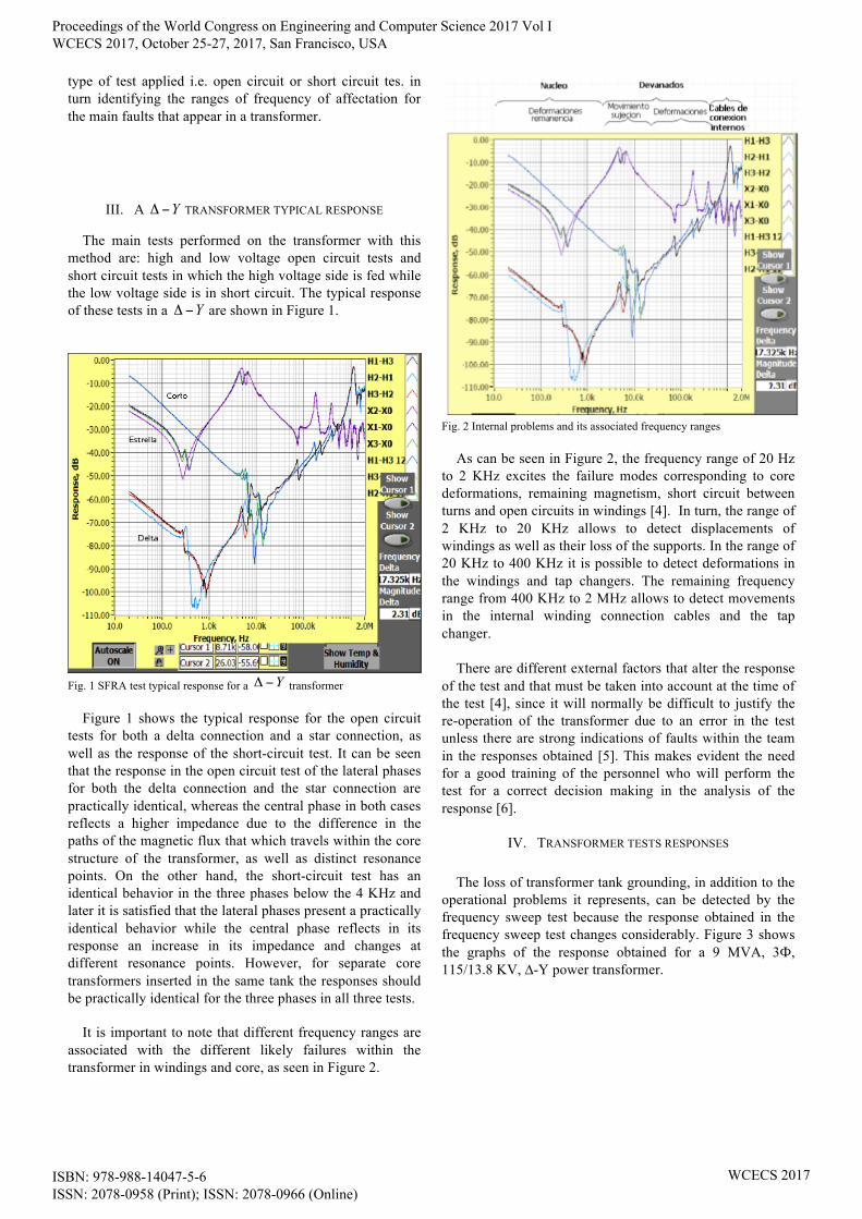
It is important to note that different frequency ranges are associated with the different likely failures within the transformer in windings and core, as seen in Figure 2.
Fig. 2 Internal problems and its associated frequency ranges
As can be seen in Figure 2, the frequency range of 20 Hz to 2 KHz excites the failure modes corresponding to core deformations, remaining magnetism, short circuit between turns and open circuits in windings [4]. In turn, the range of 2 KHz to 20 KHz allows to detect displacements of windings as well as their loss of the supports. In the range of 20 KHz to 400 KHz it is possible to detect deformations in the windings and tap changers. The remaining frequency range from 400 KHz to 2 MHz allows to detect movements in the internal winding connection cables and the tap changer.
There are different external factors that alter the response
of the test and that must be taken into account at the time of the test [4], since it will normally be difficult to justify the re-operation of the transformer due to an error in the test unless there are strong indications of faults within the team in the responses obtained [5]. This makes evident the need for a good training of the personnel who will perform the test for a correct decision making in the analysis of the response [6].
IV. TRANSFORMER TESTS RESPONSES
The loss of transformer tank grounding, in addition to the operational problems it represents, can be detected by the frequency sweep test because the response obtained in the frequency sweep test changes considerably. Figure 3 shows the graphs of the response obtained for a 9 MVA, 3Ф, 115/13.8 KV, ∆-Υ power transformer.
Proceedings of the World Congress on Engineering and Computer Science 2017 Vol I WCECS 2017, October 25-27, 2017, San Francisco, USA
ISBN: 978-988-14047-5-6 ISSN: 2078-0958 (Print); ISSN: 2078-0966 (Online)
WCECS 2017

Fig. 3 Defective core grounding
As it can be seen in Figure 3, mainly in the range of 200
Hz to 7 KHz the response without grounding of the core presents a significant change in the slope of the obtained response, being easily identifiable. However, it is necessary to have the factory sfra fingerprint test of the transformer for accurate interpretation of the problem.
With respect to the presence of contaminants in nozzles as well as in the screws of the flanges thereof i.e. the open circuit tests, Figures 4 and 5 show different behaviors in the presence of these contaminants, so that the comparison of typical responses may be sufficient to identify some of these faults. For other types of faults it will be necessary to have the factory tests of the transformer under analysis.
Fig. 4 Bushings contaminants presence part 2
Fig. 5 Bushings contaminants presence part 2
The short circuit test is also subject to faults due to connection errors. These are mainly due to a non-effective short-circuit in the secondary transformer nozzles, as it can be seen in Figure 6, where the variation of the three-phase responses at low and medium frequencies can be observed.
Fig. 6 Short circuit tips faults
Faults in the tap changer connections present a peculiar
response on the low voltage side, even though the changer is on the high voltage side, as seen in the central phase response of the transformer shown in Figure 7.
Fig. 7 Tap changer fault
As can be seen in the different failures in the performance of the tests presented in this work shows the importance of
Proceedings of the World Congress on Engineering and Computer Science 2017 Vol I WCECS 2017, October 25-27, 2017, San Francisco, USA
ISBN: 978-988-14047-5-6 ISSN: 2078-0958 (Print); ISSN: 2078-0966 (Online)
WCECS 2017

their in-field detection. This will allow to have effective responses for their analysis and timely detection of faults inside the windings or core that allow the right decisionmaking.
V. CONCLUSIONS
External factors to the transformer can alter the response obtained in the SFRA test. The in-field timely detection of this type of errors in the tests will avoid the need to repeat them with its implications of pulling out the transformer again. It is important to be sure that the tests were performed correctly to avoid misinterpretations of test results. In this work we have shown several examples of the some common cases made when performing the SFRA test. The experience of the personnel conducting these tests, with adequate training, will minimize the risk of committing these types of errors.
REFERENCES [1] Luwendran Moodley, eTheKwini Municipality and Brian de Klerk,
Sweep frequency response analysis as a diagnostic tool to detect transformer mechanical integrity, Congress The Association of Municipal Electricity Undertakings Southern Africa 2006.
[2] Larry Coffeen, Charles Sweetser, Different Aspects of Frequency Response Analysis (FRA), IEEE/PES Transformers Committee Spring 2002 Meeting Vancober, B.C., Canada April 14-18, 2002.
[3] Sandra C. Flores V., “Análisis de la Respuesta a la Frecuencia en Pruebas de Campo a Transformadores de Potencia”, tesis de licenciatura, Nov. 2010.
[4] Sánchez Servando, Avalos Alberto, Pérez Carlos. “FIELD AND LABORATORY EXPERENCES IN SWEEP FREQUENCY IN TRANSFORMERS”, Doble Engineering Company- 75th Annual International Doble Client Conference, 2008.
[5] J. Kim, B. Park, S. Jeong, S. Kim, and P. Park, "Fault diagnosis of a power transformer using an improved frequency-response analysis," IEEE Transactions on Power Delivery, vol. 20, p. 169, 2005.
[6] K. Abeywickrama, Y. Serdyuk, and S. Gubanski, "Exploring possibilities for characterization of power transformer insulation by frequency response analysis (FRA)," IEEE Transactions on Power Delivery, vol. 21, p. 1375, 2006.
[7] J. Pleite, C. Gonzalez, J. Vazquez, and A. Lazaro, "Power transformer core fault diagnosis using frequency response analysis," in MELECON 2006, Benalmadena (Malaga), Spain, 2006, pp. 1126- 1129.
Proceedings of the World Congress on Engineering and Computer Science 2017 Vol I WCECS 2017, October 25-27, 2017, San Francisco, USA
ISBN: 978-988-14047-5-6 ISSN: 2078-0958 (Print); ISSN: 2078-0966 (Online)
WCECS 2017