non-linear optimization of cylindrical electrostatic …
TRANSCRIPT
International Journal of Mass Spectrometv and Zon Processes, 84 (1988) 255-269 Elsevier Science Publishers B.V., Amsterdam - Printed in The Netherlands
255
NON-LINEAR OPTIMIZATION ELECTROSTATIC LENSES
A. VERTES *, P. JUHASZ, L. BALAZS
OF CYLINDRICAL
Central Research Institute for Physics, Hungarian Academy of Sciences, P.O. Box 49, H-1.525 Budapest 114 (Hungaryl
M. DE WOLF and R. GIJBELS
University of Antwerp (U.I.A.), Department of Chemistry, B-2610 Wilrijk (Belgium)
(First received 3 November 1987; in final form 28 January 1988)
ABSTRACT
A method and computer code to design high-transmission cylindrical electrostratic lenses has been developed. Optimized geometries and voltages are determined using the CYLENS program enhanced with the simplex method of non-linear optimization.
The possibility of improvements over unipotential lenses used in commercial instruments is predicted. The design of high-transmission unipotential lenses is described for such special purposes as time-of-flight mass spectrometry of organic ions or reflection geometry laser ionization mass spectrometry. Low accelerating voltage, in the first case and large working distance, in the second case have been realized, keeping the objective of high transmission.
Asymmetric potential lenses were also investigated and, in the deceleration regime, they turned out to be superior to low accelerating voltage unipotential lenses.
Misalignment and stability studies show that lens optimization provides less vulnerability towards anomalies in manufacturing or in operating conditions.
INTRODUCTION
The design of ion optical devices always includes a critical step where a compromise has to be found between the objectives of the experimenter and the technological possibilities. This step is called optimization or, in the language of mathemathics, solving an extremum problem with constraints.
This extremum problem naturally depends on the goal of the ion optical element itself. For instance, in the case of imaging optics, e.g. electron or ion
* To whom correspondence should be addressed. Present address: University of Antwerp (U.I.A.), Department of Chemistry, Universiteitsplein 1, B-2610 Wilrijk (Belgium). Electronic mail: [email protected]
0168-1176/88/$03.50 0 1988 Elsevier Science Publishers B.V.
256
microscopes, minimum distortion is required, while in the case of mass analyzer ion optics, maximum transmission is usually wanted. In the case of complete mass spectrometers, the aim to achieve maximum mass resolution is quite often combined with other demands such as, for example, small aberrations of the ion optics or high overall transmission.
The technological constraints one faces are related to geometrical and power requirements and to the present state of the art of electronics and structural materials used in the realization of the equipment. These cate- gories comprise, for instance, the quality of insulators, stability of power supplies, time resolution of recording devices or, among others, most simply the geometrical space which is available to accommodate the set-up.
We can generally formulate the mathematical problem of design as the minimization of non-linear function, Y(R,V, I), of many parameters R,V,I. These parameters are divided into three groups according to their nature. R stands for all the geometrical data of the ion-optical element, while V and I denote all the necessary voltages and currents, respectively.
Usually, there are upper and lower boundaries on all the independent variables leading to a finite volume in the parameter space, where the extremum has to be found
R,<R<R, (la) v, I v I V” (lb) I, I I I I” (14 In obeying these conditions, we are looking for the parameter values R* ,V * ,I * which satisfy the equation
min Y(R,V,I) = Y(R*,V*,I*) (2) n,v,r In the case of simple Y(R,V,I) functions, this problem is usually solved
analytically. In the case of ion optical problems, however, it is necessary to solve the appropriate equations of electrodynamics and mechanics in order to obtain the form of Y(R,V,I) and a direct analytical solution is usually not possible.
As an example, we can consider the treatment of cylindrical electrostatic lenses. The traditional approach to lens design has been either to confine the problem to situations where the approximate solutions of the paraxial ray equations could be used, or to find a good handbook where numerical results for multitudes of practically important cases were tabulated [l]. In both cases, the lengthy procedure of finding the particular configuration most suited to the problem remained the work of the designer. It is also obvious that, because of practical (mainly computational) limitations, the search for the optimum always remained incomplete. Possibilities for experi-
257
mental optimization are even more limited since every separate trial geome- try requires the manufacture of the given lens.
For minimization of complicated non-linear functions, the application of simplex methods proved to be very effective [2,3]. Our idea was to combine this powerful tool with the Fourier transform method and the CYLENS computer code previously described by us [4]. We intended to develop a method for designing high-transmission electrostatic lenses to be used in mass spectrometry. Although large computer-aided ion optical design pro- grams like TRIO [5] and GIOS [6] offer optimization options, their demand for memory and computation time are not always compatible with the possibilities of most of the laboratories. Nevertheless, one has to expect an enormous increase in the computation time if paraxial conditions for the rays are not fulfilled. Handling non-paraxial rays is standard in our method [4]. At the same time, even some well-developed and user friendly lens design programs do not have the possibility of automatic optimization [7], restricting the user to the ineffective and laborious trial-and-error method.
Experimental optimization of a complete thermal ion source has been reported before with the simplex method [8] and proved to be effective and reliable in adjusting all the electrical parameters of the source. The objective of this previous work was, however, quite different from ours since it aimed at the experimental determination of optimum conditions for operating an existing ion source, while our goal was to design one for a given purpose. For this, we need a mathematical model of the source, which will be outlined in the next section.
A currently important, but somewhat difficult, application of electrostatic lenses is the directional focusing of high-energy ions generated by laser plasma ionization. Unlike the case of electron-impact ionization, where ion energies are typically thermal, in laser plasma ionization, ion energies up to several hundred eV are common. At these energies, the usual conditions for Gaussian and paraxial beams are not met and so the description of the problem is only possible by numerical methods and computers.
METHODS OF CALCULATION
In the search for high-transmission electrostatic lenses, we confine our- selves to cylindrically symmetric cases and we exclude the effect of space and surface charge. The only reason for imposing these restrictions is to keep the mathematical model simple enough so as not to consume an excessive amount of computer time.
Calculations that optimize the transmission of an ion lens with as many as four or five free parameters require the determination of many potential distributions and ion trajectories for the different lenses considered. In our

258
earlier paper [4], a fast and accurate method was outlined to calculate a potential field and to trace ion trajectories inside such a field. Here, the essence will be briefly recapitulated.
If the geometry of the lens is axisymmetric, it is advantageous to use the Fourier transform method to solve the Laplace equation. The lens is placed in a cylindrical coordinate system so that its axis coincides with the z axis of the coordinate system and p is used for the radial coordinate. Clearly, the electrostatic potential inside the lens depends on z and p only: + = +( p, z). f(z) denotes the function that takes the boundary conditions into account, i.e. $(r,z) = f(z). Here, r is the radius of the lens, which is kept constant throughout the calculations. The electrostatic potential inside the lens can be written as
$(p,z) = 1-y eiWZF, [ f] # dw (3)
where F,[ f] stands for the (complex) Fourier transform of f(z), with respect to the z coordinate, and I, is the modified Bessel function of zeroth order. The solution, Eq. (3) allows us to evaluate rapidly the electrostatic potential at a very large number of points. For 512 X 80 = 40 960 points, this calcula- tion takes only a few minutes on a personal computer. In the case of grids, one has to make special considerations since the method in this simple form can handle lenses with prescribed potential on a cylindrical surface.
Ion trajectories are derived as numerical solutions of the Newtonian equations of motion in cylindrical coordinates. For differential equations of the type y” = f(x,y), the Cowell-Numerov approximation was used. It turned out to be especially effective [9] in providing the neceassary accuracy. As long as cylindrical symmetry of the field is maintained, our description remains valid. In addition, trajectories starting off-axis can also be de- scribed. This feature is important if the source of charged particles has extension comparable with the diameter of the lens.
The transmission, T, was calculated by following a large number of trajectories. Individual ion paths differed in the initial values of ion kinetic energy, E,, and departing angle, a,,. These values are defined by the ion formation process, e.g. by pulsed laser beam interaction with a solid sample. They also depend on the geometry of the ion source, e.g. “reflection” or “ transmission” geometry [lo]. In the case of reflection geometry, experimen- tal data are available [ll], but for transmission geometry, no reliable information exists at the present time. Even when performing transmission calculations with acceptable ion kinetic and angular distributions for the transmission geometry, it is not straightforward to achieve satisfactory agreement with experimental data, as we have argued elsewhere [12].
Therefore, we have assumed, somewhat arbitrarily, uniform distributions in the regions 0 eV I E, I 200 eV and - 90 o I (Y,, I 90 O. We sorted the ion paths as passed or unpassed depending on their exit angle at the point where they leave the lens. The decision was made on the basis of a limiting angle: ions that have a larger exit angle than the applied limiting angle cannot reach the window of the detector. By determining the transmitted fraction of 15 X 15 = 225 or 31 X 31= 961 trajectories, the functional dependence of transmission from lens configurations, T(R,V), could be established.
For non-linear optimization problems, the simplex methods are rather convenient and readily programmable [2,3]. We have made use of the variant described by Nelder and Mead [3] for our calculations.
We realized the algorithm by a FORTRAN source code as an extension of the existing CYLENS lens design program. Program development and trial runs could be done on an IBM PC/XT personal computer, while the main body of the calculations was carried out on a VAX 11/780 machine. Time consumption for a four-dimensional lens optimization cycle was about 90 min CPU time.
RESULTS AND DISCUSSION
We can formulate our task as a special case of the extremum problem described by Eq. (2)
Fin T(R,V) = T(R* ,V * )
where T(R,V) denotes the transmission of the lens as a function of its geometrical, R, and voltage parameters, V. Although, in principle, it is possible to optimize the ion optical element under consideration with respect to minimal aberrations as well, we looked only for the largest possible transmission since our application did not require anything else.
With the simplex method, it generally took us less then 100 steps to find the optimum in a four-dimensional parameter space. Comparing this result with the effectiveness of the conventional straightforward searching method, one can conclude that not more then three levels of each parameter could be independently tried at the same expense: “Jloo = 3.16. This would give us a much lower accuracy than that achieved by simplex optimization.
Here, we present an overview of the general tendencies observed while optimizing cylindrical lenses. We consider this type of discussion to be more beneficial than presenting lots of geometrical and voltage data of optimized lenses. Recognized tendencies can serve as a first guide to the designing process and finer details may be exploited according to the specific needs. In addition, we present a brief discussion of sensitivity investigations which
260
constitute the basis of the so-called misalignment and stability problems and are therefore of great importance in practice. The types of lenses that have been investigated are (a) three-tube unipotential lenses, (b) large working distance unipotential lenses, (c) low accelerating voltage lenses, and (d) asymmetric voltage lenses.
A sketch of the initial geometry and description of the rays (even their time development) was given in ref. 4. Parameters which describe a three-tube lens are the length of the first two electrodes H/D, L2/D, the size of the accelerating and interelectrode gaps SO/D, Sl/D all expressed in units of the tube diameter, D, and the voltages of the second and third tube U2/Ul, U3/Ul, expressed in units of the accelerating voltage, Ul. The length of the third tube is not important since, at its exit, the rays have to be colinear with the axis. We fixed the Ul and SO/D values since, by increasing Ul or by decreasing SO/D, only trivial improvements would have been encountered. In this way, the five parameters to be optimized were R = (Ll/D, L2/D, Sl/D) and V = (U2/Ul, U3/Ul). Unipotential lenses are characterized by the U3/Ul = 1 condition, and therefore the number of free parameters decreases to four. We have investigated lenses at different but fixed SO/D and Ul values. Large working distance lenses, for which SO/D L 1, and low accelerating voltage lenses, for which Ul I 2500 V, are discussed separately. The reason for this separation is explained in the appropriate sub-sections.
Three-tube unipotential lenses
Two kinds of optimization have been made depending on the presence of an entrance aperture at the front side of the lens. The diameter of this aperture was 0.40. Extensive calculations showed that there is no effect of this aperture on the transmission of the lens up to the 200 eV limiting energies we investigated. So, for the rest of our calculations, we included the aperture since higher energy ions are better eliminated as early as possible to avoid unnecessary space-charge effects. Optimization results are shown in Table 1. The length of the accelerating region was fixed at SO/D = 0.575 and optimizations were made at three different values of the accelerating voltage. It is encouraging that the decline of the transmission with decreas- ing accelerating voltage is not dramatic. From Table 1, one can see that the optimized geometries are quite similar. For comparison, data are also given for the ion lens used in the commercial LAMMAB500 laser microprobe mass analyzer [ 131.
The most characteristic parameter of the unipotential lenses is the lens voltage, U2/ Ul. The rule of thumb that the ratio of U2/ Ul should be around l/3 is well recognized over a wide range of accelerating voltage. The
261
TABLE 1
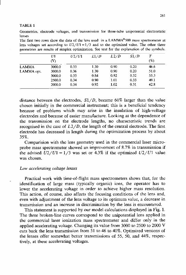
Geometries, electrode voltages, and transmission for three-tube unipotential electrostatic lenses The first two rows show the data of the lens used in a LAMMA@ mass spectrometer at lens voltages set according to U2/U1= l/3 and to the optimized value. The other three geometries are results of simplex optimization. See text for the explanation of the symbols.
u2/ u1 Ll/D L2/D Sl/D
LAMMA 3000.0 0.33 1.30 0.90 0.20 46.6 LAMMA opt. 3000.0 0.36 1.30 0.90 0.20 51.0
3000.0 0.33 0.84 0.92 0.32 55.3 2500.0 0.34 0.90 1.01 0.33 49.1 2000.0 0.34 0.92 1.02 0.31 42.8
distance between the electrodes, S/D, became 60% larger than the value chosen initially in the commercial instrument; this is a beneficial tendency because of problems which may arise in the insulation of high-voltage electrodes and because of easier manufacture. Looking at the dependence of the transmission on the electrode lengths, no characteristic trends are recognised in the case of L2/D, the length of the central electrode. The first electrode has decreased in length during the optimization process by about 35%.
Comparision with the lens geometry used in the commercial laser micro- probe mass spectrometer showed an improvement of 8.7% in transmission if the advised U2/Ul = l/3 was set or 4.3% if the optimized U2/Ul value was chosen.
Low accelerating voltage lenses
Practical work with time-of-flight mass spectrometers shows that, for the identification of large mass (typically organic) ions, the operator has to lower the accelerating voltage in order to achieve higher mass resolution. This action, of course, also affects the focusing conditions of the lens and, even with adjustment of the lens voltage to its optimum value, a decrease in transmission and an increase in discrimination by the lens is encountered.
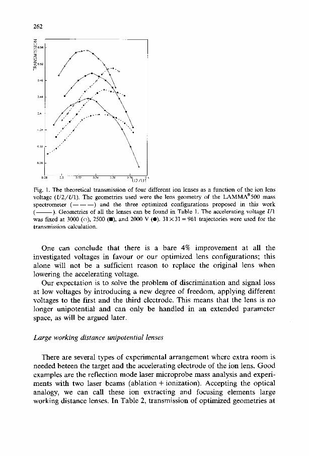
This statement is supported by our model calculations displayed in Fig. 1. The three broken-line curves correspond to the unipotential lens applied in the commercial laser ionization mass spectrometer and differ only in the applied accelerating voltage. Changing its value from 3000 to 2500 to 2000 V cuts back the lens transmission from 51 to 46 to 40%. Optimized versions of the lenses offer somewhat better transmissions of 55, 50, and 44%, respec- tively, at these accelerating voltages.
262
Fig. 1. The theoretical transmission of four different ion lenses as a function of the ion lens voltage (U2/Ul). The geometries used were the lens geometry of the LAMMA@ mass spectrometer (- - -) and the three optimized configurations proposed in this work (- ). Geometries of all the lenses can be found in Table 1. The accelerating voltage Ul was fixed at 3000 (o), 2500 (m), and 2000 V (0). 31 X 31= 961 trajectories were used for the transmission calculation.
One can conclude that there is a bare 4% improvement at all the investigated voltages in favour or our optimized lens configurations; this alone will not be a sufficient reason to replace the original lens when lowering the accelerating voltage.
Our expectation is to solve the problem of discrimination and signal loss at low voltages by introducing a new degree of freedom, applying different voltages to the first and the third electrode. This means that the lens is no longer unipotential and can only be handled in an extended parameter space, as will be argued later.
Large working distance unipotential lenses
There are several types of experimental arrangement where extra room is needed beteen the target and the accelerating electrode of the ion lens. Good examples are the reflection mode laser microprobe mass analysis and experi- ments with two laser beams (ablation + ionization). Accepting the optical analogy, we can call these ion extracting and focusing elements large working distance lenses. In Table 2, transmission of optimized geometries at

263
TABLE 2
Optimized parameters for large working distance unipotential lenses The accelerating voltage was kept constant at 3000 V.
SO/D L1/D L2/D Sl,‘D U2/Ul
0.3 1.30 0.96 0.26 0.33 55.1 0.5 1.16 1.03 0.29 0.36 50.7 1.0 1.23 0.89 0.25 0.43 41.3 1.5 1.29 = 0.83 0.28 0.5 = 32.0 2.0 1.27 = 0.89 = 0.25 0.5 a 20.9 2.5 1.23 = 0.88 = 0.24 = 0.5 = 16.4
a These data had less influence on the transmission.
different values of the accelerating gap size, SO/D, are shown. Since the accelerating voltage, Ul is fixed at 3000 V throughout the runs, one can also visualize the difference between these lenses as the difference in the field strength in the accelerating region.
From Table 2, we can conclude that as the lens is drawn back from the target, the transmission decreases almost linearly over the region up to SO/D = 2.0. Above this value, the decrease becomes less pronounced. To a certain extent, transmissions at high working distances are insensitive to the electrode length and to the lens voltage, indicating the degradation of focussing possibilities at elevated working distances.
The most characteristic feature of the SO/D dependence is the shift of optimal lens voltages toward higher values compared with the rule of thumb mentioned above. Instead of U2/Ul = 0.33, we can observe U2/Ul = 0.5. Using the optical analogy, this behaviour corresponds to that of zoom lenses.
Asymmetric voltage lenses
In order to combine strong directional focusing with low flight velocity and consequently high mass resolution in the case of time-of-flight mass spectrometry, it is a natural idea to electrically decouple the first and the third electrodes in a unipotential lens. Providing high field strength in the accelerating region and low potential on the third electrode we may achieve both of these objectives. The main question remains, which configuration and which voltage settings can realize similar transmission in an asymmetric voltage lens to that obtained in the case of unipotential lenses?
To find these data, we set up a simplex search in a five-dimensional parameter space. Instead of fixing the accelerating voltage, here we fixed U3
264
TABLE 3
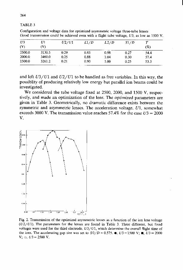
Configuration and voltage data for optimized asymmetric voltage three-tube lenses Good transmission could be achieved even with a flight tube voltage, U3, as low as 1500 V.
u2/ u1 Ll/D L2/D Sl/D
2500.0 3130.5 0.29 0.85 0.98 0.27 54.4 2000.0 3460.0 0.25 0.88 1.04 0.30 57.4 1500.0 3261.2 0.21 0.90 1.00 0.25 53.3
and left U3/Ul and U2/Ul to be handled as free variables. In this way, the possiblity of producing relatively low energy but parallel ion beams could be investigated.
We considered the tube voltage fixed at 2500, 2000, and 1500 V, respec- tively, and made an optimization of the lens. The optimized parameters are given in Table 3. Geometrically, no dramatic difference exists between the symmetric and asymmetric lenses. The acceleration voltage, Ul, somewhat exceeds 3000 V. The transmission value reaches 57.4% for the case U3 = 2000
Fig. 2. Transmission of the optimized asymmetric lenses as a function of the ion lens voltage (U2/Ul). The parameters for the lenses are found in Table 3. Three different, but fixed voltages were used for the third electrode, U3/Ul, which determine the overall flight time of the ions. The accelerating gap size was set to SO/D = 0.575. 0, U3 =1500 V; n , U3 = 2000 V; o, U3=2500 V.
265
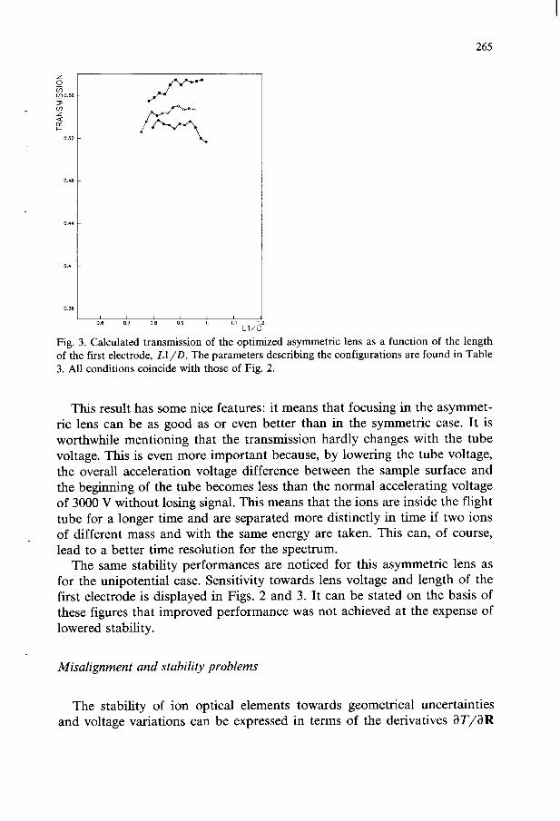
Fig. 3. Calculated transmission of the optimized asymmetric lens as a function of the length of the first electrode, Ll/D. The parameters describing the configurations are found in Table 3. All conditions coincide with those of Fig. 2.
This result has some nice features: it means that focusing in the asymmet- ric lens can be as good as or even better than in the symmetric case. It is worthwhile mentioning that the transmission hardly changes with the tube voltage. This is even more important because, by lowering the tube voltage, the overall acceleration voltage difference between the sample surface and the beginning of the tube becomes less than the normal accelerating voltage of 3000 V without losing signal. This means that the ions are inside the flight tube for a longer time and are separated more distinctly in time if two ions of different mass and with the same energy are taken. This can, of course, lead to a better time resolution for the spectrum.
The same stability performances are noticed for this asymmetric lens as for the unipotential case. Sensitivity towards lens voltage and length of the first electrode is displayed in Figs. 2 and 3. It can be stated on the basis of these figures that improved performance was not achieved at the expense of lowered stability.
Misalignment and stability problems
The stability of ion optical elements towards geometrical uncertainties and voltage variations can be expressed in terms of the derivatives aT/ClR
and aT/aV. If we are in the neighbourhood of the optimum, these deriva- tives are close to zero.
aT i-11 av z 0 v=v*
w In other words, this means that, after optimization, we also expect some improvement in stability. Since no analytic formulae are available for the transmission, we calculate its dependence from several variables.
On the basis of our experience with the simplex optimization, we picked out the two variables U2/Ul and Ll/D, which had the most significant influence on the transmission. In the case of U2/Ul, the effect of power supply instabilities can be traced, while in the case of Ll/D, the conse- quence of anomalies in manufacturing and of misalignment can be investi- gated.
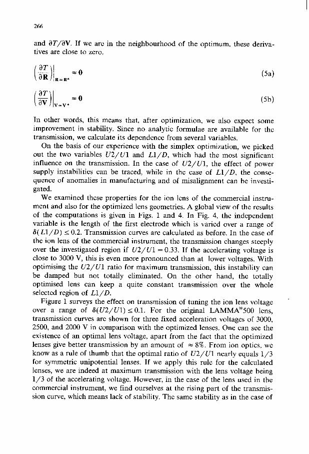
We examined these properties for the ion lens of the commercial instru- ment and also for the optimized lens geometries. A global view of the results of the computations is given in Figs. 1 and 4. In Fig. 4, the independent variable is the length of the first electrode which is varied over a range of S( Ll/D) < 0.2. Transmission curves are calculated as before. In the case of the ion lens of the commercial instrument, the transmission changes steeply over the investigated region if U2/Ul = 0.33. If the accelerating voltage is close to 3000 V, this is even more pronounced than at lower voltages. With optimising the U2/Ul ratio for maximum transmission, this instability can be damped but not totally eliminated. On the other hand, the totally optimised lens can keep a quite constant transmission over the whole selected region of Ll/D.
Figure 1 surveys the effect on transmission of tuning the ion lens voltage over a range of 6( U2/Ul) I 0.1. For the original LAMMA@ lens, transmission curves are shown for three fixed acceleration voltages of 3000, 2500, and 2000 V in comparison with the optimized lenses. One can see the existence of an optimal lens voltage, apart from the fact that the optimized lenses give better transmission by an amount of = 8%. From ion optics, we know as a rule of thumb that the optimal ratio of U2/Ul nearly equals l/3 for symmetric unipotential lenses. If we apply this rule for the calculated lenses, we are indeed at maximum transmission with the lens voltage being l/3 of the accelerating voltage. However, in the case of the lens used in the commercial instrument, we find ourselves at the rising part of the transmis- sion curve, which means lack of stability. The same stability as in the case of
267
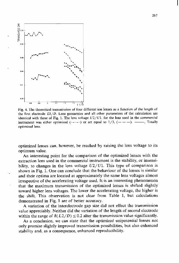
b Fig. 4. The theoretical transmission of four different ion lenses as a function of the length of the first electrode U/D. Lens geometries and all other parameters of the calculation are identical with those of Fig. 1. The lens voltage U2/Ul, for the lens used in the commercial instrument was either optimized (. - .- .) or set equal to l/3, (- - -). -, Totally optimized lens.
optimized lenses can, however, be reached by raising the lens voltage to its optimum value.
An interesting point for the comparison of the optimized lenses with the extraction lens used in the commercial instrument is the stability, or insensi- bility, to changes in the lens voltage U2/Ul. This type of comparison is shown in Fig. 1. One can conclude that the behaviour of the lenses is similar and their optima are located at approximately the same lens voltages almost irrespective of the accelerating voltage used. It is an interesting phenomenon that the maximum transmission of the optimized lenses is shifted slightly toward higher lens voltages. The lower the accelerating voltage, the higher is the shift. This observation is not clear from Table 1, but calculations demonstrated in Fig. 1 are of better accuracy.
A variation of the interelectrode gap size did not effect the transmission value appreciably. Neither did the variation of the length of second electrode within the range of 6( L2/D) I 0.2 alter the transmission value significantly.
As a conclusion, we can state that the optimized unipotential lenses not only promise slightly improved transmission possibilities, but also enhanced stability and, as a consequence, enhanced reproducibility.
268
SUMMARY
We have developed a numerical method to determine optimized geom and voltage conditions for cylindrical electrostatic lenses. In order to 1 the calculation feasible, an effective procedure was needed to pro accurate potential distributions and ion trajectories. For every geometry voltage setting, the potential distribution was calculated by the Fou transform method and hundreds of trajectories were traced by Cowell-Numerov algorithm to evaluate lens transmission.
Geometries and electrode voltages were generated by the Nelder-Mc version of the simplex algorithm which proved to be effective in finding optimized configuration. In a four-dimensional parameter space, optimi; parameter values were usually discovered in less than 100 steps.
As a practical example, the directional focusing of high-energy ions three tube lenses has been investigated.
In order to test the computional method, we checked the configuratio of three-tube unipotential lenses starting from the geometry used in commercial instrument, the LAMMA@ laser microprobe time-of-flig mass spectrometer. Although, according to our expectations, we could n achieve dramatic improvements in performance compared with that of tl built-in ion lens, small refinements were possible. The original transmissic of 47% could be increased to 55% by small modifications, mainly lo adjusting the lens voltage, by increasing the interelectrode gap size b = 60% and decreasing the length of the first electrode by = 35%.
We compared the performance of the commercial lens and of our opt] mized configurations at lower accelerating voltages. This regime is inter esting because lowering the accelerating voltage increases the mass resolu tion of a time-of-flight mass spectrometer. Changing the accelerating voltagl from 3000 to 2000 V cuts back transmission by about lo%, independent o optimization.
Large working distance lenses have been designed up to SO/D = 2.t working distance. It turned out that, on increasing the working distance, the most important parameter to adjust is the lens voltage. Its value increases from U2/Ul= 0.33 to 0.5. So “zoom-like” behaviour of these lenses was observed.
A promising solution of increasing mass resolution and keeping transmis- sion high at the same time is the introduction of asymmetric voltage lenses. Optimized parameters have been found at three different tube voltages for the asymmetric case. It was possible to regain more than 24% in transmis- sion at a tube voltage as low as 1500 V.
Investigation of lens stabilities confirmed our expectations that optimized lenses are less sensitive to anomalies in the parameter values. It was also

possibile to determine which parameters have the which parameters can be set with more tolerance. In the lens voltage and the length of the first electrode significant from this point of view.
269
largets influence and the case of our lenses, turned out to be most
REFERENCES
9
10 11 12
13
E. Harting and F.H. Read, Electrostatic Lenses, Elsevier, New York, 1976, pp. 43-281. R. Fletcher and M.J.D. Powell, Comput. J., 6 (1963) 163. J.A. Nelder and R. Mead, Comput. J., 7 (1965) 308. A. Vertes, P. Juhasz and L. Matus, Int. J. Mass Spectrom. Ion Processes, 73 (1986) 109. T. Matsuo, Jpn. J. Appl. Phys., 23 (1984) 1518. H. Wollnik, J. Brezina and M. Berz, Nucl. Instrum. Methods A, 258 (1987) 408. J.E. Delmore, Int. J. Mass Spectrom. Ion Processes, 67 (1985) 121. H.T. Shaw, S. Niemeyer and G.F. Hunt, Int. J. Mass Spectrom. Ion Processes, 68 (1986) 317. W. Ledermann (Ed.), Handbook of Applicable Mathematics, Vol. 3, Wiley, New York, 1981, pp. 350-352. F. Hillenkamp, E. Unsold, R. Kaufmann and R. Nitsche, Appl. Phys., 8 (1975) 341. R.J. Conzemius and J.M. Capellen, Int. J. Mass Spectrom. Ion Phys., 34 (1980) 197. M. De Wolf, T. Mauney, E. Michiels and R. Gijbels, Scanning Electron Microsc., 3 (1986) 799. Leybold-Heraeus, Cologne, F.R.G.