non-linear optical frequency conversion crystals for space...
TRANSCRIPT

Non-linear optical frequency conversion crystals for space applications
Alessandra Ciapponi1, Wolfgang Riede1, Georgios Tzeremes2, Helmut Schröder1, Peter Mahnke1
1German Aerospace Center (DLR e.V.), Institute of Technical Physics, Stuttgart, Germany
2European Space Agency (ESA / ESTEC), Noordwijk, The Netherlands
ABSTRACT
Reliable, long term operation of high-power laser systems in the Earth orbit is not a straightforward task as the space environment entails various risks for optical surfaces and bulk materials. The increased operational risk is, among others, due to the presence of high energy radiation penetrating the metallic shielding of satellites and inducing absorption centers in the bulk of optical components, and vacuum exposure which can deteriorate coating performance. Comprehensive testing for analyzing high-energy radiation effects and mitigation procedures were performed on a set of frequency conversion crystals and are discussed in this paper. In addition to a general resistance to space environmental effects, the frequency conversion crystals were subjected to a comparative analysis on optimum third harmonic efficiency, starting from pulsed 1064 nm laser radiation, with the goal of exceeding a value of 30 %. Concomitant modeling supported the selection of crystal parameters and the definition of crystal dimensions. Keywords: Frequency conversion, space qualification, laser damage, non-linear crystal, proton / gamma irradiation
1. INTRODUCTION Non-linear optical crystals which are used as frequency converters to access various spectral ranges like the visible or UV are key components of space-based LIDAR systems. There is an ongoing need for the development and the manufacturing of non-linear crystals with high efficiency, improved hardness against optical damage, and color-center free UV operation. The qualification has to take into account typical operational conditions encountered in a space environment, which are long term exposure to ultra-high vacuum and high energy radiation, thermal cycling, vibration, and long term operation under the presence of fundamental Nd:YAG laser radiation and its harmonics. The investigations at the optics qualification laboratory at DLR are intended to support upcoming ESA missions like ADM Aeolus and ATLID to guarantee the availability of top quality components [1]. Promising candidate crystals for frequency conversion are borates like LBO, BBO, BiBO, and gray-tracking resistant KTP (KTPgr). To investigate a possible radiative degradation under exposure to high energy radiation like cosmic rays, proton and gamma radiation tests were performed. The total dose used for the tests was equivalent to a 3 year orbital dose for protons and gamma rays. Depending on the orbit, it can reach a value of up to 100 krad of gamma irradiation and up to 1012 protons/cm2, potentially inducing displacement damage in the crystal structure [2]. The dose rates are several orders of magnitude higher than under operational conditions, in order to reduce the test duration. Degradation was monitored by measuring the optical transmission before and after each irradiation. Efficient and long term stable operation is of uttermost importance for operation of lasers in space. The frequency conversion stage is a laser subsystem where an optimization and hence an improvement of overall laser performance can be achieved. The current baseline for third harmonic generation for ESA space laser missions under vacuum conditions is a combination of LBO crystals (LBO type I as SHG and LBO type II as THG) [3]. The main goal is to achieve a high conversion efficiency for radiation at 355 nm. For this purpose promising new conversion crystals like BiBO are compared with standard converters under vacuum and atmospheric conditions.
E-Mail: [email protected] Phone: +49-711-6862-751 Internet: www.dlr.de/tp

2. FREQUENCY CONVERSION TESTS 2.1 INTRODUCTION The introduction of Q-switched Nd:YAG lasers operating at 1064 nm for space applications makes LBO, BBO, BiBO, and KTP excellent candidates for frequency converters. To check the availability of operative crystals from European providers, a set of crystals for frequency SHG and THG conversion was procured (c. f. Tab 1). The non-linear crystals have to be tested and optimized for space applications.
2.2 NON-LINEAR CRYSTAL SAMPLES The selection of crystal types was made according to certain requirements. First of all the achievable frequency conversion value had to be larger than 30 %. In addition, a high laser-induced damage threshold of the AR coatings with a target value of 15 J/cm2 at a wavelength of 355 nm for ns pulses was stipulated. Further selection properties of the crystals were a large acceptance angle and a small walk-off angle. The samples had to be non-hygroscopic and tolerant under gamma and proton irradiation. All crystals were cut for non-critical phase matching at 56.8°C. Overall, 25 operative long crystals with lengths of 6 – 20 mm were subjected to the tests. Furthermore, 24 thin slices with a thickness of 2 mm mainly used for LIDT testing and investigating bulk thickness effects were acquired. All samples were double-band or triple-band AR coated at the corresponding wavelengths with dense coatings based on ion-beam sputtering, ion-assisted deposition or magnetron sputtering, and had a cross-section of 10 mm x 10 mm. Table 1 summarizes the principal characteristics of the selected crystals. The most recent crystal on market is BiBO, which is grown since the 2000 and available on market without inclusions at reasonable size since 2007 [4].
Crystal
Phase matching
type
deff (pm/V)
θ (deg) Φ (deg) Walk-off angle (mrad)
ΔΦ/Δθ (deg)
l = 1cm
Temperature bandwidth (K)
l = 1cm
LBO (SHG)
I 0.836 90 10 6.03 0.27/2.63 5.8-6.7
BBO (SHG)
I 2.01 22.9 55.8 0.021 37-51
BiBO (SHG)
I 3.00 168 90 27.55 0.04 1.3
KTPgr (SHG)
II 3.56 90 24.3 4.28 0.58/1.82 20
LBO (THG)
II 0.52 44.4 90 9.5 0.79/0.16 6
BBO (THG)
I 2.01 31.4 72.24 0.011-0.015 16
BiBO (THG)
I 3.9 145.7 90 68.6 0.051/0.024 0.9
Table 1: Properties of SHG and THG crystals investigated in this work (LBO, BBO, BiBO and KTPgr). Typical impurity levels are < 10 ppm for LBO and ~ 100 ppm for KTP. 2.3 MODELING For second harmonic generation three coupled non-linear differential equations for the electric field amplitudes of the three interacting waves can be derived from the Maxwell equations. For high peak power and good beam quality, the conversion efficiency can reach more than 50 %. Therefore it is important to consider the depletion of the fundamental beam as well as the phase mismatch for an adequate description of the conversion process. Regarding the latter, Armstrong et al. [5] have solved the coupled equations for arbitrary k and intensities in the infinite plane wave approximation for second harmonic generation. In Eq.1 the solution is used in a format which was deduced by Eimerl et. al [6].

20
2 ,/ mmmsn (1) with
12(1212
0
2
0
2
m
Ilnc
dc
eff 2
30
200
22
0
8 2/ckl 2/
0
nk
In equation (1) above, defines the conversion efficiency, is the dephasing, I is the pump intensity, /n0 is the angular sensitivity, is the FWHM beam divergence of the fundamental beam, lc is the length of the nonlinear crystal and sn(n,k) is the jacobi elliptic function. Fig. 1 shows the SHG conversion efficiency for KTP, BBO and BiBO in dependence on the crystal length. The fact that the beam has a Gaussian like profile was taken into account, by calculating the conversion according to equation (1) for each intensity and integration over the beam profile. From these curves the optimum crystal lengths for SHG conversion were extracted to be 5.5 mm for KTP, 6.3 mm for BiBO and 7.8 mm for BBO for a beam divergence of 0.3 mrad and a peak fluence of 3 J/cm². The calculated crystal lengths were considered as a minimum length for defining the real crystal dimensions.
Figure 1: SHG conversion efficiency for KTP (upper curve), BiBO (middle) and BBO (lower curve) as function of crystal length (calculation is valid for a beam divergence of 0.3 mrad and a Gaussian peak fluence of 3 J/cm²).

2.4 EXPERIMENTAL SETUP The set-up used for the efficiency tests is depicted in Fig. 2 below. The laser source is a seeded Nd:YAG laser (Innolas Spitlight-Hybrid) operating at 1064 nm with a repetition rate of 100 Hz, a pulse duration of 10 ns (FWHM) and a beam quality factor M² = 1.8 . In order to control the pump pulse energy on the crystals an attenuator made up by a half-wave plate and a polarizer is adjusted manually. A telescope for divergence and beam diameter control is introduced in the beam path. Laser pulse energy and beam profiles are monitored with a power meter and a CCD camera, respectively. A collinear HeNe laser is used for alignment of the beam path. Dichroic mirrors allowed to separate the converted wavelengths from the fundamental wavelength. The doubling and tripling stages are located inside a UHV chamber (c.f. Fig. 3 below) providing a background pressure of 10-9 mbar. The chamber is assembled from commercial stainless steel fittings with a nominal diameter of 200 mm and copper sealing. Inconel Helicoflex ring sealings are used to tighten the chamber windows. Generally, the usage of any outgassing material is avoided, if possible, as even materials qualified for CVCM values below 0.1 % will induce contamination damage on crystal facets inside the chamber [7]. A 2-stage dry turbo pump system was used under dynamic pumping. The absence of laser-induced contamination inside the chamber was confirmed by monitoring any fluorescence emission from the exit chamber window induced by the UV light. All crystals were operated under non-critical phase-matching conditions and kept under vacuum for 12 h prior to the test itself to allow the crystals to accommodate to representative vacuum conditions.
Figure 2: Experimental setup for frequency conversion. The dual wave /2 plate between SHG and THG crystal is utilized in case of identical phase matching type for SHG and THG.
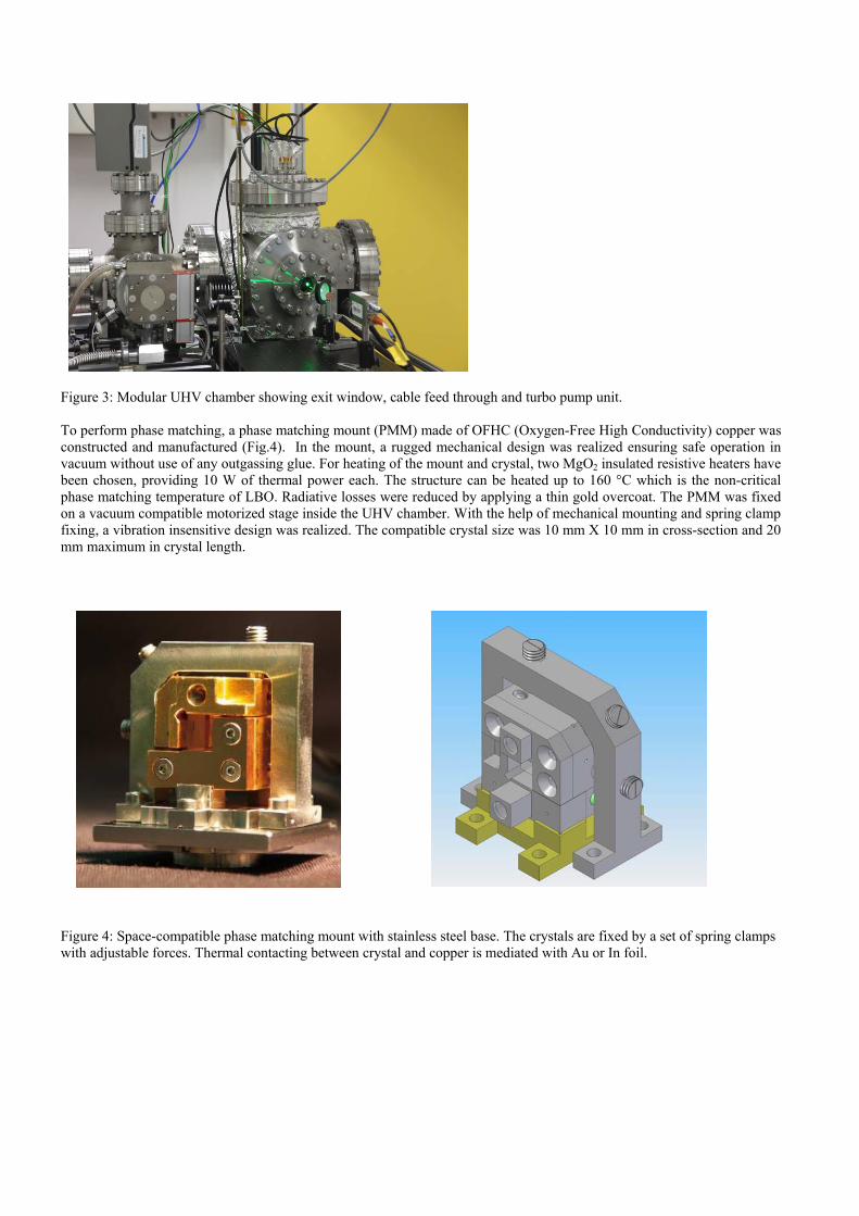
Figure 3: Modular UHV chamber showing exit window, cable feed through and turbo pump unit. To perform phase matching, a phase matching mount (PMM) made of OFHC (Oxygen-Free High Conductivity) copper was constructed and manufactured (Fig.4). In the mount, a rugged mechanical design was realized ensuring safe operation in vacuum without use of any outgassing glue. For heating of the mount and crystal, two MgO2 insulated resistive heaters have been chosen, providing 10 W of thermal power each. The structure can be heated up to 160 °C which is the non-critical phase matching temperature of LBO. Radiative losses were reduced by applying a thin gold overcoat. The PMM was fixed on a vacuum compatible motorized stage inside the UHV chamber. With the help of mechanical mounting and spring clamp fixing, a vibration insensitive design was realized. The compatible crystal size was 10 mm X 10 mm in cross-section and 20 mm maximum in crystal length.
Figure 4: Space-compatible phase matching mount with stainless steel base. The crystals are fixed by a set of spring clamps with adjustable forces. Thermal contacting between crystal and copper is mediated with Au or In foil.
2.5 RESULTS
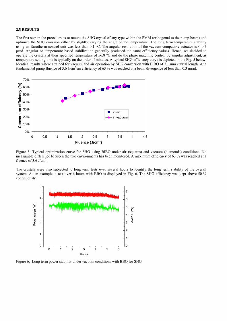
The first step in the procedure is to mount the SHG crystal of any type within the PMM (orthogonal to the pump beam) and optimize the SHG emission either by slightly varying the angle or the temperature. The long term temperature stability using an Eurotherm control unit was less than 0.1 °C. The angular resolution of the vacuum-compatible actuator is < 0.7 µrad. Angular or temperature based stabilization generally produced the same efficiency values. Hence, we decided to operate the crystals at their specified temperature of 56.8 °C and do the phase matching control by angular adjustment, as temperature setting time is typically on the order of minutes. A typical SHG efficiency curve is depicted in the Fig. 5 below. Identical results where attained for vacuum and air operation by SHG conversion with BiBO of 7.1 mm crystal length. At a fundamental pump fluence of 3.6 J/cm2 an efficiency of 63 % was reached at a beam divergence of less than 0.3 mrad. Figure 5: Typical optimization curve for SHG using BiBO under air (squares) and vacuum (diamonds) conditions. No measurable difference between the two environments has been monitored. A maximum efficiency of 63 % was reached at a fluence of 3.6 J/cm2. The crystals were also subjected to long term tests over several hours to identify the long term stability of the overall system. As an example, a test over 6 hours with BBO is displayed in Fig. 6. The SHG efficiency was kept above 50 % continuously. Figure 6: Long term power stability under vacuum conditions with BBO for SHG.
0%
10%
20%
30%
40%
50%
60%
70%
0 0,5 1 1,5 2 2,5 3 3,5 4 4,5
Fluence (J/cm²)
Co
nve
rsio
n e
ffic
ien
cy (
%)
in air
in vacuum

In the Tab. 2 below are summarized the optimum SHG efficiencies of the investigated crystals under air and vacuum operation. Identical efficiency values were reached for both operational conditions.
Crystal
SHG in air Efficiency / Diameter / Divergence
SHG in vacuum Efficiency / Diameter / Divergence
LBO 56 % / 2.7 mm / 0.6 mrad 52 % / 2.7 mm / 0.6 mrad
BBO 51 % / 1.6 mm / 0.6 mrad 51 % / 1.6 mm / 0.6 mrad
BiBO 61 % / 2.2 mm / 0.2 mrad
63 % / 2.0 mm / 0.3 mrad
KTPgr 63 % / 0.95 mm / 0.95 mrad 55 % / 0.95 mm / 0.95 mrad
Table 2: Summary of the results for the SHG crystals tested for air and vacuum operation. The beam parameters 1 / e2 beam diameter and full angle divergence are also stated. In case of KTP tests, the exit facet showed surface damage, which is the reason for the lower value in vacuum. After optimization of the SHG emission, the THG crystal is positioned in the vacuum chamber at a distance of 7 cm from the SHG unit. Both PMMs are identical. The THG crystals are also operated at a temperature of 56.8°C. Fig.8 shows a optimization curve for a combination of SHG BiBO (type I) and THG BiBO (type I). Figure 7: Optimization curve for THG using BiBO / BiBO under operation in air. A maximum efficiency of 41 % was reached at a fluence of 1.6 J/cm2. In the Tab. 3 below are summarized the optimum THG efficiencies of the investigated crystals under air and vacuum operation. Identical efficiency values were reached for both operational conditions.
0
5
10
15
20
25
30
35
40
45
0 0,5 1 1,5 2
Fluence (J/cm²)
Co
nve
rsio
n e
ffic
ien
cy (
%)

Crystal
THG in air Efficiency / Diameter / Divergence
THG in vacuum Efficiency / Diameter / Divergence
LBO/LBO 34 % / 2.7 mm / 0.6 mrad 34 % / 2.7 mm / 0.6 mrad
BBO/BBO 32 % / 1.6 mm / 0.6 mrad 32 % / 1.6 mm / 0.6 mrad
BiBO/BiBO 41 % / 1 mm / 0.84 mrad
-
BiBO/BBO 31 % / 1 mm / 0.6 mrad 31 % / 1 mm / 0.6 mrad
BiBO/LBO 35 % / 1 mm / 1.2 mrad 35 % / 1 mm / 1.2 mrad
Table 3: Summary of the results for the THG crystals tested under air and vacuum operation. The beam parameters 1 / e2 beam diameter and full angle divergence are also stated. During BiBO/BiBO tests, a damage at the exit facet of the THG crystal showed surface damage. All the combinations tested exceeded an efficiency value of 30. Some of these combinations reach higher conversion like LBO plus LBO, BiBO plus LBO and BiBO plus BiBO. Unfortunately for this last combination damage in THG crystal occurred during the initial test in air in a configuration that was not the standard one. A distance of 40 cm between the SHG and THG crystals was used. Further investigations are needed in order to provide results with the standard configuration used for the other crystals.
3. HIGH ENERGY RADIATION TESTS High energy radiation will generally affect the transmission of non-linear optical crystals [8]. The test philosophy of the high energy radiation tests was to apply under strongly accelerated test conditions a three year equivalent orbital dose of p+ or gamma radiation within several hours to the optical components which are assumed to be several 1011 p+/cm2, or up to 1012 p+/cm2, at proton test energies at three different energy levels of 10, 100, 250 MeV, in case of protons, and 100 krad overall dose in case of gamma irradiation. For investigation of radiation induced degradation effects the optical transmission of the crystals was measured before and after each irradiation step 3. 1 RADIATION TESTS
Fig. 8 shows a schematic of the experimental set-up used for the transmission measurements. The light source is a combination of a deuterium and halogen lamp. The main intensity is in the region of 200-500 nm for the deuterium and 400-2000 nm for the halogen lamp. The light is fiber coupled to a collimator lens L1. For polarization of the light a broadband Glan-laser polarizer (-BBO) is used. The spot size diameter on the sample is approximately 3 mm. The crystals are adjusted (by rotation) in such a way, that the light passes as ordinary beam through the crystals. Thereby any beam deviation is prevented. The transmitted light is focused by a lens L2 to a second fiber, which guides the light to a grating spectrometer (Ocean Optics HR 4000) with Si-Detector which is sensitive between 200 and 1100 nm. The resolution of the spectrometer is in the range of 0.4 nm, while the measurement uncertainty is in the order of 0.5%. For mobile operation at the irradiation sites the transmission set-up is mounted on an optical breadboard and protected by an aluminum cover.

Figure 8: Mobile Transmission Spectrometer. Lp: Deuterium/Halogen Lamp, Pol: Polarizer, P: Pinhole, S: sample, L1, L2: lenses, SP: grating spectrometer.
3.2 IRRADIATION FACILITIES AND PARAMETERS
The gamma irradiation tests were performed at the ESTEC radiation facility in Noordwijk, NL with a 60Co source which emits gamma quanta with 1.17 and 1.33 MeV energy. Fig. 9 shows the 60Co radiation facility and the holder with the samples under test. The sample holder was designed to hold up to 12 crystals of different length, arranged in a circle so that the dose rate is equal for each crystal. The entrance faces of the crystals were in the same plane. The irradiation direction was same as the light propagation during XHG operation. The dose rate was adjusted by the distance between sample holder and source. The irradiations were done in air at room temperature. The irradiation parameters are shown in Table 4. 100 krad is the equivalent total dose for a three year stay in orbit. The fourth irradiation was applied only to the Borates (LBO, BiBO, BBO).
Dose
[krad]
Dose rate
[krad/h]
Exposure time
[h]
1st irradiation 10 3.6 2.8
2nd irradiation 30 1.8 16.7
3rd irradiation 60 3.1 19.4
4th irradiation 100 44 2.3
Table 4: Gamma irradiation test parameters.

Figure 9: Gamma radiation facility at ESTEC.
The proton irradiation tests were performed at the Proton Irradiation Facility (PIF) and Proscan of the Paul-Scherrer-Institute (PSI, CH). The energy levels selected for testing are 10.8 MeV, 100 MeV and 230 MeV. The irradiations were performed in two runs: a low energy irradiation at 10.8 MeV with a total dose of 6.5 1011 p+/cm² and a high energy irradiation at 100 MeV and 230 MeV with a total dose of 7.2 1011 p+/cm². The detailed test parameters are shown in Table 5. The irradiations were performed at ambient air atmosphere and room temperature. The holder was the same as used for gamma irradiations.
Energy
[MeV]
Dose
[1011 p+/cm²]
Flux
[108 p+/cm²s]
Exposure time
[min]
1st irradiation 10.8 2.5 1.3 32
2nd irradiation
10.8 4.0 1.4 47
3rd irradiation
100 3.6 1.8 60
4th irradiation 230 3.6 0.7 90
Table 5: Protonirradiation test parameters.
3.3 RESULTS OF GAMMA RADIATION TESTS
The transmission spectra for the Borate crystals BiBO and LBO were totally unaffected by the applied gamma irradiations. Even after a total dose of 200 krad and a high dose rate irradiation, the transmission showed no degradation in the whole spectral range from 300-1000 nm. The BBO crystal was not affected by the first two irradiations with a total dose of 40 krad. After the third irradiation (100 krad total dose) a slight degradation (approximately 1.5% at 532 nm) was observed. This degradation increased to 2.5% after the additional applied 100 krad irradiation. The KTPgr crystal on the other side showed a strong reduction of transmission after the gamma irradiations (Fig. 10). The penetration depth for the 1.17 and 1.33 MeV gamma photons is much longer than the crystal length. Therefore an isotropic bulk effect is expected for the transmission degradation. For the KTPgr crystal the radiation induced absorption has a broad maximum between 350 and 550 nm. For 532 nm the transmission was reduced from 98% to 73 %. Above 700nm the transmission loss was less than 10% and for 1000 nm less than 5%.

Figure 10: Transmission spectra of (coated) KTPgr (lhs) and LBO (rhs) before and after gamma irradiation.
To investigate the influence of dose rate on the transmission, two identical RTP (Rubidium Titanyl Phosphate) crystals were irradiated with different dose rates but identical total dose (100 krad). The first sample was irradiated in one step (2.3 h) with 44 krad/h while the second was irradiated in three steps: 2.8 h at 3.6 krad/h, 16.7 h at 1.8 krad/h and 19.7 h at 3.1 krad/h. There was nearly the same transmission loss for both crystals. It appears that the degradation effect is determined by the total dose and independent on the dose rate. But it should be mentioned, that even the low dose rate in our tests is several orders of magnitude higher than realistic dose rates in orbit.
3.4 RESULTS OF PROTON RADIATION TESTS
For the borate crystals LBO, BBO and BiBO there was no degradation detectable with respect to the transmission in the whole spectral range between 300 and 1000 nm after low and high energy proton irradiations within the measurement uncertainty of 0.5 %. In contrast to the borates for the KTPgr crystal a clear transmission degradation was seen both for the low and high energy irradiations. Similar to the degradation effects observed after gamma irradiation the proton radiation induced an increasing absorption with decreasing wavelength (Fig. 11 and 12). A partial self annealing at room temperature of the transmission degradation was observed by measuring the transmission several days after the irradiation tests. The recovery was complete after a 2 hours annealing at 150°C in vacuum.
Figure 11: Transmission spectra for BBO and KTPgr crystals before and after low energy (10.8 MeV) proton irradiation.

Figure 12: Transmission spectra for BiBO and KTPgr crystals before and after high energy irradiations with 100 MeV and 230 MeV protons.
4. CONCLUSIONS
In this paper, a comprehensive survey of nonlinear optical crystal performance under space conditions is made with focus on achievable THG efficiency and resistance to high energy radiation. The results indicate that BiBO is an excellent candidate for SHG comparable in terms of efficiency with KTP. In the course of extended THG tests, several combinations have exceeded an efficiency of 31 %. Initial tests with BiBO / BiBO delivered promisingly high values > 40% which have to be confirmed in further test campaigns. Still, optimization potential is expected from variation of the length of selected crystals. Long term tests showed the stability of the system and comparison between vacuum and air operation revealed no measurable differences. Still, safe operation well below the LID threshold is an important issue. Irradiation tests with gamma and low and high energy protons, with a total dose equivalent to a 3 years stay in orbit showed no transmission degradation for LBO and BiBO crystals in the wavelength range between 300 and 1000 nm. BBO showed a small degradation (< 1.5%) after 100 krad gamma irradiation. For KTPgr a strong transmission reduction was observed after gamma and proton irradiations. A partial recovery at room temperature and a complete recovery after annealing (150°C, 2 h) was observed.
ACKNOWLEDGEMENTS The authors acknowledge the support of W. Hajdas from Paul-Scherrer Institute in Villigen, CH, and B. Nickson from the European Space Research and Technology Centre during the proton and gamma radiation test campaigns. Valuable technical assistance was given at the DLR labs by F. Hadinger and G. Taube. The support from European Space Agency for this activity is gratefully acknowledged.
REFERENCES
[1] Nett, H., Endemann, M., “Atmospheric Dynamics Mission: Aeolus”, Geoscience and Remote Sensing Symposium, 2004. IGARSS '04. Proceedings, (2004). [2] European Standard ECSS-E-ST-10-04C, “Space engineering: Space environment”, European Cooperation for Space Standardization, 2008 [3] Y. Durand, LIDAR technology developments in support of ESA Earth observation missions, International conference on space optics 2008. [4] Private communication, S. Vernay, Research institute for mineral and metallic materials (FEE, Idar-Oberstein, Germany)

[5] J.A. Armstrong, N. Bloembergen, J. Ducuing, P.S. Pershan; “Interactions between Light Waves in a Nonlinear Dielectric”; Phys. Rev. 127(6); 1918-1939 (1962) [6] D. Eimerl, S. Velsko, L. Davis and F. Wang; “Progress in Nonlinear Optical Materials for High Power Lasers”, Prog. Crystal Growth and Charact. (20), 59-113 (1990) [7] Lien, Y, Wernham, D., Riede, W., Allenspacher, P., „Risk mitigation in space borne lasers“, Photonics Europe, Strasbourg, France (2006). [8] U. Roth et al. “Proton and gamma radiation tests on nonlinear crystals”, Applied Optics Vol.41 (464-469), No. 3, 2002.