nomenclature and symbology conventionsbaydeltaoffice.water.ca.gov/modeling/hydrology/calsim3/... ·...
TRANSCRIPT

4-1 DRAFT – December 2017
Chapter 4 Network Schematic The foundation of the CalSim 3.0 development is a schematic representing the water system of the Sacramento River and San Joaquin River hydrologic regions and the Sacramento-San Joaquin Delta (Delta). The schematic is in the form of a node-arc network. Nodes represent specific locations, such as water control facilities, stream junctions, points of diversions, and return flows. Arcs represent flows between nodes. Mass balance must be observed at each node (i.e., flows in the incoming arcs equal flows in the outgoing arcs except at nodes representing reservoirs where a change in storage may occur). The CalSim 3.0 schematic is available both in a rectilinear “circuit board” form and georeferenced form.
This chapter discusses CalSim 3.0 conventions for representing the surface water conveyance system. Appendix C describes the physical water infrastructure of the Sacramento River Hydrologic Region and Delta, and how the water supply system and water users are represented in the CalSim schematic.
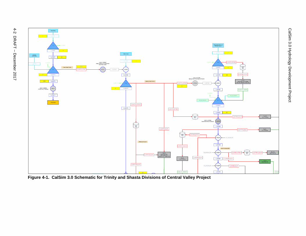
Nomenclature and Symbology Conventions The CalSim 3.0 schematic is too large to reproduce in its entirety in this report. However, examples of parts of the schematic are presented in Figure 4-1 and Figure 4-2. CalSim 3.0 has considerably greater spatial detail relative to CalSim II. For example, CalSim II considers seven water use regions in the Sacramento Valley, termed Depletion Study Areas (DSA). Water demands in each DSA are disaggregated into ‘project’ demands and ‘non-project’ demands. In contrast, CalSim 3.0 simulates water demands, deliveries, and return flows associated with 145 demand units. While this additional information allows for more detailed analyses, it also sets the stage for potential confusion. Therefore, a simple nomenclature has been developed to bring clarity to the CalSim 3.0 schematic.
The adopted nomenclature establishes generic standards for a subset of CalSim Water Resources Simulation Language (WRESL) code, known as “system files.” These standards are intended to provide transparency, reduce the time investment required to learn and understand CalSim 3.0, facilitate error detection, and accommodate future additions and development of the model. Conventions have been kept brief for clarity and practicality (shorter naming conventions keep names intelligible and memorable). Moreover, the Water Resources Integrated Modeling System (WRIMS) software limits decision-variable names to 16 characters.1
1 This limitation has since been removed in WRIMS release 1.3.4 and later.
CalSim
3.0 Hydrology D
evelopment Project
4-2 DR
AFT – Decem
ber 2017
Figure 4-1. CalSim 3.0 Schematic for Trinity and Shasta Divisions of Central Valley Project

Chapter 4: N
etwork Schem
atic
4-3 DR
AFT – Decem
ber 2017
Figure 4-2. CalSim 3.0 Schematic for Oroville-Thermalito Complex of State Water Project
CalSim 3.0 Hydrology Development Project
4-4 DRAFT – December 2017
Naming and Style Conventions A set of conventions have been established for both naming schematic objects (i.e., arc names and node names) and the way they are illustrated (e.g., color, line format). These conventions are explained in the following sections.
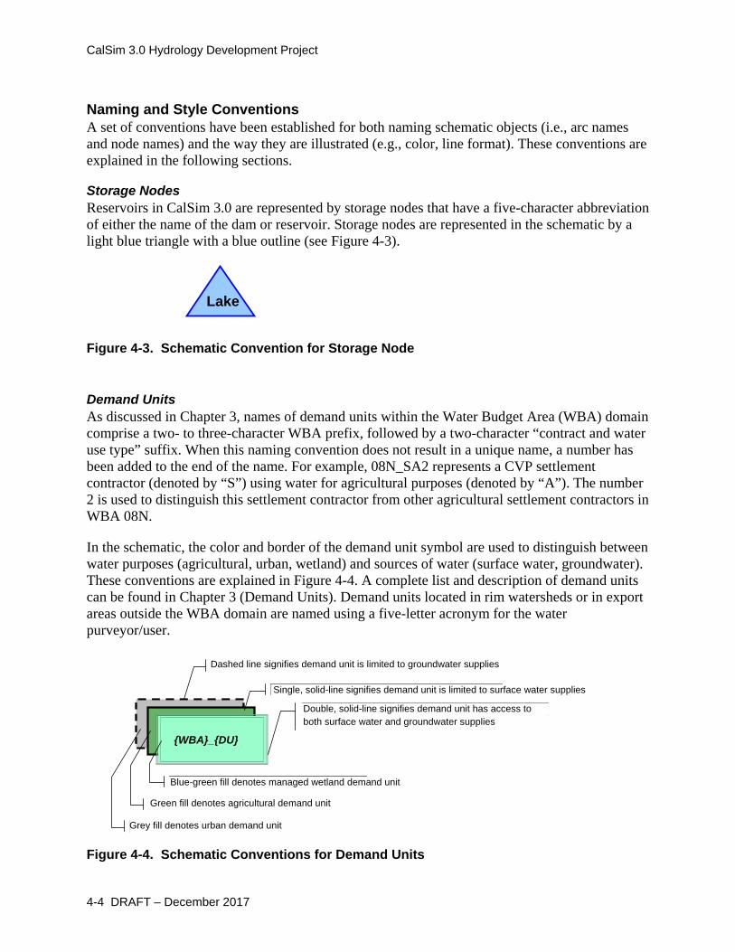
Storage Nodes Reservoirs in CalSim 3.0 are represented by storage nodes that have a five-character abbreviation of either the name of the dam or reservoir. Storage nodes are represented in the schematic by a light blue triangle with a blue outline (see Figure 4-3).
Figure 4-3. Schematic Convention for Storage Node
Demand Units As discussed in Chapter 3, names of demand units within the Water Budget Area (WBA) domain comprise a two- to three-character WBA prefix, followed by a two-character “contract and water use type” suffix. When this naming convention does not result in a unique name, a number has been added to the end of the name. For example, 08N_SA2 represents a CVP settlement contractor (denoted by “S”) using water for agricultural purposes (denoted by “A”). The number 2 is used to distinguish this settlement contractor from other agricultural settlement contractors in WBA 08N.
In the schematic, the color and border of the demand unit symbol are used to distinguish between water purposes (agricultural, urban, wetland) and sources of water (surface water, groundwater). These conventions are explained in Figure 4-4. A complete list and description of demand units can be found in Chapter 3 (Demand Units). Demand units located in rim watersheds or in export areas outside the WBA domain are named using a five-letter acronym for the water purveyor/user.
Figure 4-4. Schematic Conventions for Demand Units
Lake
77_PA 77_PA {WBA}_{DU}
Dashed line signifies demand unit is limited to groundwater supplies
Single, solid-line signifies demand unit is limited to surface water supplies
Double, solid-line signifies demand unit has access to both surface water and groundwater supplies
Grey fill denotes urban demand unit
Green fill denotes agricultural demand unit
Blue-green fill denotes managed wetland demand unit

Chapter 4: Network Schematic
4-5 DRAFT – December 2017
Conveyance Nodes The CalSim 3.0 schematic displays conveyance nodes as circles bearing a six-character “license plate” abbreviation of the conveyance name and river mile (RM) or channel milepost (MP).2 Line types and colors are used to represent a variety of node attributes. Gray outlines represent artificial or constructed conveyance channels, as opposed to blue outlines, which represent natural conveyance channels. A gray fill color indicates a gaging station or gauge location. A node with gray fill and dashed outline indicates that the gauge has been discontinued.3 Green nodes are only used to split return flows among various destinations (streams and river or reuse by other demand units). These nodes have no explicit physical location and are intended to represent diffuse drainage networks within a demand unit. These conventions are displayed in Figure 4-5.
Figure 4-5. Schematic Conventions for Conveyance Nodes
For example, Reclamation District (RD) 108 diverts water at Wilkins Slough. A streamflow gauge maintained by the U.S. Geological Survey (USGS) is located approximately 1,200 feet downstream at RM 120 (USGS 1390500, Sacramento River below Wilkins Slough near Grimes). The gauge measures flows in the Sacramento River above a conceptual point known as the Navigation Control Point (NCP). The Sacramento River is abbreviated as “SAC”; thus, the gauge node is referenced as “SAC120.” The Sacramento River is a natural channel; therefore, the node is outlined in blue. There is no stream-aquifer interaction modeled at this point; therefore the node has no associated groundwater inflow arcs. Since gauge information exists for this point, the node is given a gray fill color. Table 4-1 lists the abbreviations used to denote streams and rivers in the Sacramento River hydrologic region.
2 Names for diversion arcs incorporate both the upstream and downstream node names. For this reason, node names are 6
characters or less, which is required to keep arc names within the former 16-character limitation of WRIMS. 3 Discontinued gauge locations are included in the CalSim 3.0 schematic where the associated gauge data have been used to
develop inflow hydrology or used for model calibration.
RFS 16 Outline colors:
Blue - natural stream channel Gray - man-made canal, drain or bypass
YUB 014
Fill colors: Green - Return flow split node Approximates diffuse networks of drains Gray - streamflow gaging station
Node Name includes: 3-character abbreviation of the conveyance's name 3-digit river mile or milepost
SAC 118 TCC
000

CalSim 3.0 Hydrology Development Project
4-6 DRAFT – December 2017
Table 4-1 Naming Convention for Channel Arcs in Sacramento River Hydrologic Region Prefix Channel Name Prefix Channel Name ABN Auburn Ravine KRT Kelly Ridge Tunnel/Powerhouse ABT Auburn Tunnel KLR Knights Landing Ridge Cut AMR American River LBC Lower Boardman Canal ANT Antelope Creek LBR Little Bear River BCC Big Chico Creek LCC Little Chico Creek BCN Berar Creek (North) LDC Little Dry Creek BEC Bear River Canal LLC Little Last Chance Creek BGC Big Grizzly Creek LRT Lohman Ridge Tunnel BGD Biggs-West Gridley Drain LST Lost Creek BRC Bear Creek (tributary to Cache Creek) MFA Middle Fork American BRR Bear River LVC Lake Valley Canal BSL Butte Slough LVP Los Vaqueros Pipeline BTC Butte Creek MFF Middle Fork Feather BTL Battle Creek MFY Middle Fork Yuba BTN Belden Tunnel/Powerhouse MLC Mill Creek BUK Bucks Creek MNS Minor north-east streams BVT Butt Valley Tunnel MRM Mormon Ravine CBC Combie Ophir Canal MTC M&T and Llano Seco Canal CBD Colusa Basin Drain NBA North Bay Aqueduct CCC Contra Costa Canal NFA North Fork American CCH Cache Creek NFC North Fork Cache Creek CCK Coon Creek NFF North Fork Feather River CCT Clear Creek Tunnel NFY North Fork Yuba River CGT Colgate Tunnel NNA North Branch North Fork American River CLR Clear Creek OGN Oregon Creek CMT Camptonville Tunnel OMR Old and Middle River COW Cow Creek ORP Old River Pipeline CRB Caribou Penstock/Powerhouse OWC Oroville-Wyandotte Canal CRC Natomas Cross Canal PSC Putah South Canal CRK Cherokee Canal POE Poe Tunnel/Powerhouse CSL Cache Slough PTH Putah Creek CST Cresta Tunnel/Powerhouse PYN Paynes Creek CWD Cottonwood Creek RCT Rock Creek Tunnel/Powerhouse CYN Canyon Creek RFS Return Flow Split DCK Dry Creek (tributary to Natomas East Main Drain) RSL Rock Slough DER Deer Creek (tributary to Yuba River) RVC Richvale Canal DHC Dry and Hutchinson Creek SAC Sacramento River DRC Deer Creek SBP Sutter Bypass DRM Drum Canal SCR Secret Ravine ELD Elder Creek SCT Slate Creek Tunnel EMD Natomas East Main Drain Canal SCW South Fork Cottonwood Creek ENF East Branch of North Fork Feather River SFA South Fork American River ESL Edgar Slough SFF South Fork Feather River FDC French Dry Creek SFT South Fork Tunnel FPT Forbestown Tunnel/Powerhouse SFY South Fork Yuba River FSC Folsom South Canal SEC Sutter Extension Canal FTR Feather River SLT Slate Creek GCC Glenn-Colusa Canal SPT Spring Creek Tunnel GRZ Grizzly Creek SSL Sacramento Slough HKC Hendricks Canal STH South Canal HON Honcut Creek SYC South Yuba Canal ISF Isolated Facility STN Stony Creek JBC Joint Board Canal TAB Thermalito Afterbay release JCK Jack Slough TCC Tehama-Colusa Canal
Chapter 4: Network Schematic
4-7 DRAFT – December 2017
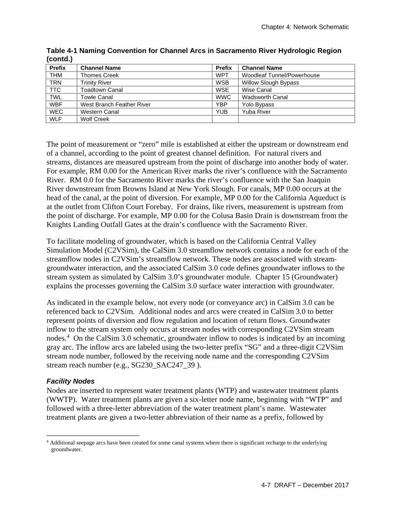
Table 4-1 Naming Convention for Channel Arcs in Sacramento River Hydrologic Region (contd.) Prefix Channel Name Prefix Channel Name THM Thomes Creek WPT Woodleaf Tunnel/Powerhouse TRN Trinity River WSB Willow Slough Bypass TTC Toadtown Canal WSE Wise Canal TWL Towle Canal WWC Wadsworth Canal WBF West Branch Feather River YBP Yolo Bypass WEC Western Canal YUB Yuba River WLF Wolf Creek
The point of measurement or “zero” mile is established at either the upstream or downstream end of a channel, according to the point of greatest channel definition. For natural rivers and streams, distances are measured upstream from the point of discharge into another body of water. For example, RM 0.00 for the American River marks the river’s confluence with the Sacramento River. RM 0.0 for the Sacramento River marks the river’s confluence with the San Joaquin River downstream from Browns Island at New York Slough. For canals, MP 0.00 occurs at the head of the canal, at the point of diversion. For example, MP 0.00 for the California Aqueduct is at the outlet from Clifton Court Forebay. For drains, like rivers, measurement is upstream from the point of discharge. For example, MP 0.00 for the Colusa Basin Drain is downstream from the Knights Landing Outfall Gates at the drain’s confluence with the Sacramento River.
To facilitate modeling of groundwater, which is based on the California Central Valley Simulation Model (C2VSim), the CalSim 3.0 streamflow network contains a node for each of the streamflow nodes in C2VSim’s streamflow network. These nodes are associated with stream-groundwater interaction, and the associated CalSim 3.0 code defines groundwater inflows to the stream system as simulated by CalSim 3.0’s groundwater module. Chapter 15 (Groundwater) explains the processes governing the CalSim 3.0 surface water interaction with groundwater.
As indicated in the example below, not every node (or conveyance arc) in CalSim 3.0 can be referenced back to C2VSim. Additional nodes and arcs were created in CalSim 3.0 to better represent points of diversion and flow regulation and location of return flows. Groundwater inflow to the stream system only occurs at stream nodes with corresponding C2VSim stream nodes.4 On the CalSim 3.0 schematic, groundwater inflow to nodes is indicated by an incoming gray arc. The inflow arcs are labeled using the two-letter prefix “SG” and a three-digit C2VSim stream node number, followed by the receiving node name and the corresponding C2VSim stream reach number (e.g., SG230_SAC247_39 ).
Facility Nodes Nodes are inserted to represent water treatment plants (WTP) and wastewater treatment plants (WWTP). Water treatment plants are given a six-letter node name, beginning with “WTP” and followed with a three-letter abbreviation of the water treatment plant’s name. Wastewater treatment plants are given a two-letter abbreviation of their name as a prefix, followed by
4 Additional seepage arcs have been created for some canal systems where there is significant recharge to the underlying
groundwater.

CalSim 3.0 Hydrology Development Project
4-8 DRAFT – December 2017
“WWTP”. Pump stations are given an abbreviation of six characters maximum length, ending in “PS”. When the naming convention does not result in a unique name, an additional number has been added to the end (e.g., DWRPS1). Figure 4-6 shows the conventions for representing these facilities.
Figure 4-6. Schematic Conventions for Conveyance and Water and Wastewater Treatment Facilities
Criteria were established for whether to include nodes for specific WTPs and WWTPs in the CalSim 3.0 schematic, based on the population served and facility capacity, as follows:
• WTPs – Capacity greater than 5 million gallons per day (mgd), or supply to a population exceeding 20,000
• WWTPs – Capacity greater than 5 mgd
In cases where facilities do not meet these criteria, diversion arcs directly connect the stream to the demand unit for water supply or connect the demand unit to the stream for wastewater return flow.
Arcs Arcs represent average monthly flows to, from, or between nodes. Arcs must connect to at least one node. Flow direction is indicated by an arrow head pointing in the direction of flow. In CalSim 3.0, arc names are generally composed of three parts: a prefix denoting the type of arc (e.g., inflow, channel, diversion); the arc’s node of origin; and the arc’s destination node. For channel arcs representing flows in a stream or constructed channel, the destination node is omitted from the arc name. For example, arc C_SAC120 represents flow downstream from RM 120 on the Sacramento River (at the location of USGS gauge 1390500). In the few cases when arcs are bidirectional (i.e., flow can occur in either direction), the schematic shows either two arcs, one arc for each direction or a single arc with arrow heads in each direction. Figure 4-7 presents arc schematic conventions. An arc composed of a series of dashes indicate that a channel does not exist at an existing level of development; either the arc represents a channel that has been discontinued or removed (e.g., the Upper Boardman Canal diversion from the Bear River), or the arc represents a planned facility that has not yet been constructed (e.g., the proposed Davis-Woodland diversion from the Sacramento River for municipal water supply).
Water Treatment Plant
Wastewater Treatment Plant
Pump Station
WTP SAC
RV_WWTP
DWR PS1

Chapter 4: Network Schematic
4-9 DRAFT – December 2017
Figure 4-7. Schematic Conventions for Arcs
To facilitate comparison with CalSim II, yellow highlighted boxes appear throughout the CalSim 3.0 schematic representing equivalent CalSim II storage nodes or CalSim II flow arcs. For example, the arc representing inflow to Shasta Lake is labeled “I_SHSTA.” A yellow box appears next to this arc label to indicate that the same arc is represented in CalSim II as “I4.”
CalSim User Interface The CalSim 3.0 schematic is stored in xml format for direct use within the WRIMS environment. The schematic may be viewed and edited within WRIMS 2. Model results may also be displayed on the schematic. The schematic can be readily exported to pdf format. The pdf format provides some level of user interaction, allowing the search of node and arc names. An example of the schematic loaded into the WRIMS environment is shown in Figure 4-8.
CalSim Georeferenced Schematic The CalSim 3.0 schematic has been georeferenced and is available as an ESRI geodatabase. The georeferenced schematic proved to be invaluable in constructing the connectivity and to ground-truth the representation of California’s water system in node-arc format. The georeferenced schematic is available in kmz file format for viewing with Google Earth. A set of pdf files have been produced that show the georeferenced schematic overlain on a USGS base map. A set of five maps cover the Sacramento Valley portion of the CalSim 3.0 schematic. An example of part of the georeferenced schematic is illustrated in Figure 4-9.
Line Type and Color WRESL Prefixes Description
C(hannel) - River or stream flows
C(hannel) - Canal or drain flows
SP(ill) - Spill or flood bypass flows
D(iversion) - Diversion – typically to demand unit
R(eturn flow) - Return flow – typically from demand unit
I(nflow) - Rim watershed inflows
SR (Surface Runoff) - Rainfall-runoff within the valley floor

CalSim
3.0 Hydrology D
evelopment Project
4-10 DR
AFT – Decem
ber 2017
Figure 4-8. WRIMS 2.0 User Interface

Chapter 4: N
etwork Schem
atic
4-11 DR
AFT – Decem
ber 2017
Figure 4-9. CalSim 3.0 Georeferenced Schematic for Southern End of Colusa Basin Drain and Sutter Bypass

CalSim 3.0 Hydrology Development Project
4-12 DRAFT – December 2017
This page left blank intentionally.

Chapter 4: Network Schematic
4-13 DRAFT – December 2017
Chapter 4 Network Schematic ............................................................................................ 4-1 Nomenclature and Symbology Conventions ............................................................................ 4-1
Naming and Style Conventions ....................................................................................... 4-4 CalSim User Interface ............................................................................................................... 4-9 CalSim Georeferenced Schematic ............................................................................................ 4-9
Table 4-1 Naming Convention for Channel Arcs in Sacramento River Hydrologic Region ...... 4-6 Table 4-1 Naming Convention for Channel Arcs in Sacramento River Hydrologic Region
(contd.) .................................................................................................................... 4-7 Figure 4-1. CalSim 3.0 Schematic for Trinity and Shasta Divisions of Central Valley Project . 4-2 Figure 4-2. CalSim 3.0 Schematic for Oroville-Thermalito Complex of State Water Project ... 4-3 Figure 4-3. Schematic Convention for Storage Node ................................................................. 4-4 Figure 4-4. Schematic Conventions for Demand Units .............................................................. 4-4 Figure 4-5. Schematic Conventions for Conveyance Nodes ...................................................... 4-5 Figure 4-6. Schematic Conventions for Conveyance and Water and Wastewater Treatment
Facilities .................................................................................................................. 4-8 Figure 4-7. Schematic Conventions for Arcs .............................................................................. 4-9 Figure 4-8. WRIMS 2.0 User Interface .................................................................................... 4-10 Figure 4-9. CalSim 3.0 Georeferenced Schematic for Southern End of Colusa Basin Drain and
Sutter Bypass ........................................................................................................ 4-11