no. np-t-3 · pressure vessel steels no. np-t-3.11 uides iaea nuclear energy series no. no....
TRANSCRIPT

Basic Principles
Objectives
IAEA Nuclear Energy Series
Technical Reports
Integrity of Reactor Pressure Vessels in Nuclear Power Plants: Assessment of Irradiation Embrittlement Effects in Reactor Pressure Vessel Steels
No. NP-T-3.11
Guides
IAEA Nuclear Energy Series No. No. NP-T-3.11Integrity of Reactor Pressure Vessels in Nuclear Pow
er Plants: Assessment of Irradiation Em
brittlement Effects in Reactor Pressure Vessel Steels
INTERNATIONAL ATOMIC ENERGY AGENCYVIENNA
ISBN 978–92–0–101709–3ISSN 1995–7807
156 pages, 9mm
P1382_covI-IV.indd 1 2009-05-05 11:14:48

INTEGRITY OF REACTOR PRESSURE VESSELS IN NUCLEAR POWER PLANTS:
ASSESSMENT OF IRRADIATION EMBRITTLEMENT EFFECTS
IN REACTOR PRESSURE VESSEL STEELS

The following States are Members of the International Atomic Energy Agency:
AFGHANISTANALBANIAALGERIAANGOLAARGENTINAARMENIAAUSTRALIAAUSTRIAAZERBAIJANBANGLADESHBELARUSBELGIUMBELIZEBENINBOLIVIABOSNIA AND HERZEGOVINABOTSWANABRAZILBULGARIABURKINA FASOCAMEROONCANADACENTRAL AFRICAN REPUBLICCHADCHILECHINACOLOMBIACOSTA RICACÔTE D’IVOIRECROATIACUBACYPRUSCZECH REPUBLICDEMOCRATIC REPUBLIC OF THE CONGODENMARKDOMINICAN REPUBLICECUADOREGYPTEL SALVADORERITREAESTONIAETHIOPIAFINLANDFRANCEGABONGEORGIAGERMANYGHANAGREECE
GUATEMALAHAITIHOLY SEEHONDURASHUNGARYICELANDINDIAINDONESIAIRAN, ISLAMIC REPUBLIC OF IRAQIRELANDISRAELITALYJAMAICAJAPANJORDANKAZAKHSTANKENYAKOREA, REPUBLIC OFKUWAITKYRGYZSTANLATVIALEBANONLIBERIALIBYAN ARAB JAMAHIRIYALIECHTENSTEINLITHUANIALUXEMBOURGMADAGASCARMALAWIMALAYSIAMALIMALTAMARSHALL ISLANDSMAURITANIAMAURITIUSMEXICOMONACOMONGOLIAMONTENEGROMOROCCOMOZAMBIQUEMYANMARNAMIBIANEPALNETHERLANDSNEW ZEALANDNICARAGUANIGERNIGERIANORWAY
OMANPAKISTANPALAUPANAMAPARAGUAYPERUPHILIPPINESPOLANDPORTUGALQATARREPUBLIC OF MOLDOVAROMANIARUSSIAN FEDERATIONSAUDI ARABIASENEGALSERBIASEYCHELLESSIERRA LEONESINGAPORESLOVAKIASLOVENIASOUTH AFRICASPAINSRI LANKASUDANSWEDENSWITZERLANDSYRIAN ARAB REPUBLICTAJIKISTANTHAILANDTHE FORMER YUGOSLAV REPUBLIC OF MACEDONIATUNISIATURKEYUGANDAUKRAINEUNITED ARAB EMIRATESUNITED KINGDOM OF GREAT BRITAIN AND NORTHERN IRELANDUNITED REPUBLIC OF TANZANIAUNITED STATES OF AMERICAURUGUAYUZBEKISTANVENEZUELAVIETNAMYEMENZAMBIAZIMBABWE
The Agency’s Statute was approved on 23 October 1956 by the Conference on the Statute of the IAEAheld at United Nations Headquarters, New York; it entered into force on 29 July 1957. The Headquarters of theAgency are situated in Vienna. Its principal objective is “to accelerate and enlarge the contribution of atomicenergy to peace, health and prosperity throughout the world’’.

INTEGRITY OFREACTOR PRESSURE VESSELS IN NUCLEAR POWER PLANTS:
ASSESSMENT OF IRRADIATION EMBRITTLEMENT EFFECTS
IN REACTOR PRESSURE VESSEL STEELS
IAEA NUCLEAR ENERGY SERIES No. NP-T-3.11
INTERNATIONAL ATOMIC ENERGY AGENCYVIENNA, 2009

COPYRIGHT NOTICE
All IAEA scientific and technical publications are protected by the terms of the Universal Copyright Convention as adopted in 1952 (Berne) and as revised in 1972 (Paris). The copyright has since been extended by the World Intellectual Property Organization (Geneva) to include electronic and virtual intellectual property. Permission to use whole or parts of texts contained in IAEA publications in printed or electronic form must be obtained and is usually subject to royalty agreements. Proposals for non-commercial reproductions and translations are welcomed and considered on a case-by-case basis. Enquiries should be addressed to the IAEA Publishing Section at:
Sales and Promotion, Publishing SectionInternational Atomic Energy AgencyWagramer Strasse 5P.O. Box 1001400 Vienna, Austriafax: +43 1 2600 29302tel.: +43 1 2600 22417email: [email protected] http://www.iaea.org/books
© IAEA, 2009
Printed by the IAEA in AustriaApril 2009
STI/PUB/1382
IAEA Library Cataloguing in Publication Data
Integrity of reactor pressure vessels in nuclear power plants : assessment of irradiation embrittlement effects in reactor pressure vessel steels. — Vienna : International Atomic Energy Agency, 2009.
p. ; 29 cm. — (IAEA nuclear energy series, ISSN 1995-7807 ; no. NP-T-3.11)
STI/PUB/1382ISBN 978-92-0-101709-3Includes bibliographical references.
1. Nuclear pressure vessels — Materials — Testing. 2. Light water reactors — Safety measures. 3. Steel — Effect of radiation on. 4. Steel — Embrittlement. I. International Atomic Energy Agency. II. Series.
IAEAL 09–00569

FOREWORD
IAEA Member States are giving high priority to continuing the operation of nuclear power plants beyond the timeframe originally anticipated (e.g. 30 or 40 years). As of January 2008, more than 70% of the 439 operating nuclear power plants have been in operation for more than 20 years.
Nuclear power plant operating equipment, generically called systems, structures and components (SSCs), is subjected to a variety of chemical, mechanical and physical conditions during operation. Such stressors lead to changes, over time, in the SSC materials, which are caused and driven, for example, by the effects of varying loads, flow conditions, corrosion, temperature and neutron irradiation. Time dependent changes in mechanical and physical properties of SSCs are referred to as ageing. The effects of ageing become evident with a reduction in design margins and/or an increase in forced outages and repairs of SSCs. Normally, SSC ageing effects in nuclear power plants have usually been allowed for in a conservative manner in design and manufacturing specifications.
During the operation of a nuclear power plant, the wall of the reactor pressure vessel (RPV) is exposed to neutron radiation, which results in localized embrittlement of the steel and welds in the area of the reactor core. Ageing effects of the RPV have the potential to be life-limiting conditions for a nuclear power plant as it is impossible or economically unviable to replace the RPV if its mechanical properties degrade significantly.
Research on irradiation embrittlement of RPV steels has been the subject of significant international research. Over the past three decades, developments in fracture mechanics have led to a number of consensus standards and codes for determining the needed fracture toughness parameters and associated uncertainties as derived from the embrittlement databases. This understanding has resulted in remarkable progress in developing a mechanistic understanding of irradiation embrittlement.
This report summarizes the assessment of irradiation embrittlement effects in RPV steels for Western RPVs and for WWER RPVs. The aim is to support and strengthen capabilities to optimize service life by improving the understanding of the effects of neutron irradiation on the steels and welds of LWR RPVs.
The IAEA wishes to thank the participants for their contributions, especially the meeting chairman, R. Nanstad, of the Oak Ridge National Laboratory USA. The IAEA officers responsible this publication were K. Kang and L. Kupca of the Division of Nuclear Power.

EDITORIAL NOTE
This report has been edited by the editorial staff of the IAEA to the extent considered necessary for the reader’s assistance. It does not address questions of responsibility, legal or otherwise, for acts or omissions on the part of any person.
Although great care has been taken to maintain the accuracy of information contained in this publication, neither the IAEA nor its Member States assume any responsibility for consequences which may arise from its use.
The use of particular designations of countries or territories does not imply any judgement by the publisher, the IAEA, as to the legal status of such countries or territories, of their authorities and institutions or of the delimitation of their boundaries.
The mention of names of specific companies or products (whether or not indicated as registered) does not imply any intention to infringe proprietary rights, nor should it be construed as an endorsement or recommendation on the part of the IAEA.

CONTENTS
1. INTRODUCTION . . . . . . . . . . . . . . . . . . . . . . . . . . . . . . . . . . . . . . . . . . . . . . . . . . . . . . . . . . . . . . . . . . . . . 1
1.1. Background . . . . . . . . . . . . . . . . . . . . . . . . . . . . . . . . . . . . . . . . . . . . . . . . . . . . . . . . . . . . . . . . . . . . . . 11.2. Scope . . . . . . . . . . . . . . . . . . . . . . . . . . . . . . . . . . . . . . . . . . . . . . . . . . . . . . . . . . . . . . . . . . . . . . . . . . . . 21.3. Users . . . . . . . . . . . . . . . . . . . . . . . . . . . . . . . . . . . . . . . . . . . . . . . . . . . . . . . . . . . . . . . . . . . . . . . . . . . . 31.4. Structure . . . . . . . . . . . . . . . . . . . . . . . . . . . . . . . . . . . . . . . . . . . . . . . . . . . . . . . . . . . . . . . . . . . . . . . . . 3
2. DESCRIPTION OF REACTOR PRESSURE VESSELS . . . . . . . . . . . . . . . . . . . . . . . . . . . . . . . . . . . . 3
2.1. RPV design features . . . . . . . . . . . . . . . . . . . . . . . . . . . . . . . . . . . . . . . . . . . . . . . . . . . . . . . . . . . . . . . 42.1.1. Western RPVs . . . . . . . . . . . . . . . . . . . . . . . . . . . . . . . . . . . . . . . . . . . . . . . . . . . . . . . . . . . . . . 42.1.2. WWER RPVs. . . . . . . . . . . . . . . . . . . . . . . . . . . . . . . . . . . . . . . . . . . . . . . . . . . . . . . . . . . . . . . 7
2.2. RPV materials and fabrication . . . . . . . . . . . . . . . . . . . . . . . . . . . . . . . . . . . . . . . . . . . . . . . . . . . . . . . 102.2.1. Western RPVs . . . . . . . . . . . . . . . . . . . . . . . . . . . . . . . . . . . . . . . . . . . . . . . . . . . . . . . . . . . . . . 102.2.2. WWER RPVs . . . . . . . . . . . . . . . . . . . . . . . . . . . . . . . . . . . . . . . . . . . . . . . . . . . . . . . . . . . . . . 16
2.3. Design basis: codes, regulations and guides . . . . . . . . . . . . . . . . . . . . . . . . . . . . . . . . . . . . . . . . . . . . 182.3.1. Western RPVs . . . . . . . . . . . . . . . . . . . . . . . . . . . . . . . . . . . . . . . . . . . . . . . . . . . . . . . . . . . . . . 182.3.2. WWER RPVs . . . . . . . . . . . . . . . . . . . . . . . . . . . . . . . . . . . . . . . . . . . . . . . . . . . . . . . . . . . . . . 19
2.4. NDE requirements . . . . . . . . . . . . . . . . . . . . . . . . . . . . . . . . . . . . . . . . . . . . . . . . . . . . . . . . . . . . . . . . 202.4.1. Western RPVs . . . . . . . . . . . . . . . . . . . . . . . . . . . . . . . . . . . . . . . . . . . . . . . . . . . . . . . . . . . . . . 202.4.2. WWER RPVs . . . . . . . . . . . . . . . . . . . . . . . . . . . . . . . . . . . . . . . . . . . . . . . . . . . . . . . . . . . . . . 21
3. EFFECTS OF IRRADIATION ON MECHANICAL PROPERTIES . . . . . . . . . . . . . . . . . . . . . . . . . 22
3.1. Introduction . . . . . . . . . . . . . . . . . . . . . . . . . . . . . . . . . . . . . . . . . . . . . . . . . . . . . . . . . . . . . . . . . . . . . . 223.2. Brief description of failure modes . . . . . . . . . . . . . . . . . . . . . . . . . . . . . . . . . . . . . . . . . . . . . . . . . . . . 243.3. Experimental procedures . . . . . . . . . . . . . . . . . . . . . . . . . . . . . . . . . . . . . . . . . . . . . . . . . . . . . . . . . . . 25
3.3.1. Testing techniques . . . . . . . . . . . . . . . . . . . . . . . . . . . . . . . . . . . . . . . . . . . . . . . . . . . . . . . . . . . 253.3.2. Irradiation experiments . . . . . . . . . . . . . . . . . . . . . . . . . . . . . . . . . . . . . . . . . . . . . . . . . . . . . . 403.3.3. Consensus codes and standards . . . . . . . . . . . . . . . . . . . . . . . . . . . . . . . . . . . . . . . . . . . . . . . . 41
3.4. Tensile properties and hardness . . . . . . . . . . . . . . . . . . . . . . . . . . . . . . . . . . . . . . . . . . . . . . . . . . . . . . 413.5. Notch impact toughness . . . . . . . . . . . . . . . . . . . . . . . . . . . . . . . . . . . . . . . . . . . . . . . . . . . . . . . . . . . . 413.6. Temperature, flux, fluence, spectrum . . . . . . . . . . . . . . . . . . . . . . . . . . . . . . . . . . . . . . . . . . . . . . . . . 453.7. Quasi-static fracture toughness . . . . . . . . . . . . . . . . . . . . . . . . . . . . . . . . . . . . . . . . . . . . . . . . . . . . . . 483.8. Dynamic fracture toughness and crack-arrest toughness . . . . . . . . . . . . . . . . . . . . . . . . . . . . . . . . . 493.9. Stainless steel cladding . . . . . . . . . . . . . . . . . . . . . . . . . . . . . . . . . . . . . . . . . . . . . . . . . . . . . . . . . . . . . 493.10. Correlations and normalization schemes . . . . . . . . . . . . . . . . . . . . . . . . . . . . . . . . . . . . . . . . . . . . . . 503.11. Thermal annealing and re-irradiation . . . . . . . . . . . . . . . . . . . . . . . . . . . . . . . . . . . . . . . . . . . . . . . . . 53
4. MECHANISMS GOVERNING THE IRRADIATION-INDUCED EMBRITTLEMENT OF LWR PRESSURE VESSEL STEELS . . . . . . . . . . . . . . . . . . . . . . . . . . . . . . . . . . . . . . . . . . . . . . . . . . 56
4.1. Materials and irradiation conditions . . . . . . . . . . . . . . . . . . . . . . . . . . . . . . . . . . . . . . . . . . . . . . . . . . 564.1.1. Description of materials . . . . . . . . . . . . . . . . . . . . . . . . . . . . . . . . . . . . . . . . . . . . . . . . . . . . . . 564.1.2. In-service conditions . . . . . . . . . . . . . . . . . . . . . . . . . . . . . . . . . . . . . . . . . . . . . . . . . . . . . . . . . 57
4.2. Irradiation effects in RPV steels . . . . . . . . . . . . . . . . . . . . . . . . . . . . . . . . . . . . . . . . . . . . . . . . . . . . . 584.2.1. Chemical composition . . . . . . . . . . . . . . . . . . . . . . . . . . . . . . . . . . . . . . . . . . . . . . . . . . . . . . . 594.2.2. Metallurgical structure . . . . . . . . . . . . . . . . . . . . . . . . . . . . . . . . . . . . . . . . . . . . . . . . . . . . . . . 614.2.3. Irradiation parameters . . . . . . . . . . . . . . . . . . . . . . . . . . . . . . . . . . . . . . . . . . . . . . . . . . . . . . . 614.2.4. Microstructural characterization . . . . . . . . . . . . . . . . . . . . . . . . . . . . . . . . . . . . . . . . . . . . . . . 62
4.3. Mechanisms controlling the formation of irradiation-induced defects . . . . . . . . . . . . . . . . . . . . . . 66

4.3.1. Primary damage . . . . . . . . . . . . . . . . . . . . . . . . . . . . . . . . . . . . . . . . . . . . . . . . . . . . . . . . . . . . 674.3.2. Formation and structure of hardening defects . . . . . . . . . . . . . . . . . . . . . . . . . . . . . . . . . . . 704.3.3. Phosphorus segregation . . . . . . . . . . . . . . . . . . . . . . . . . . . . . . . . . . . . . . . . . . . . . . . . . . . . . . 764.3.4. A simplified story . . . . . . . . . . . . . . . . . . . . . . . . . . . . . . . . . . . . . . . . . . . . . . . . . . . . . . . . . . . 76
4.4. Mechanisms controlling the evolution of mechanical properties . . . . . . . . . . . . . . . . . . . . . . . . . . 774.4.1. Hardening processes . . . . . . . . . . . . . . . . . . . . . . . . . . . . . . . . . . . . . . . . . . . . . . . . . . . . . . . . . 774.4.2. Embrittlement process . . . . . . . . . . . . . . . . . . . . . . . . . . . . . . . . . . . . . . . . . . . . . . . . . . . . . . . 80
4.5. Post-irradiation annealing . . . . . . . . . . . . . . . . . . . . . . . . . . . . . . . . . . . . . . . . . . . . . . . . . . . . . . . . . . 814.6. Multi-scale modelling . . . . . . . . . . . . . . . . . . . . . . . . . . . . . . . . . . . . . . . . . . . . . . . . . . . . . . . . . . . . . . 82
4.6.1. Context . . . . . . . . . . . . . . . . . . . . . . . . . . . . . . . . . . . . . . . . . . . . . . . . . . . . . . . . . . . . . . . . . . . . 824.6.2. Multi-scale simulation . . . . . . . . . . . . . . . . . . . . . . . . . . . . . . . . . . . . . . . . . . . . . . . . . . . . . . . 834.6.3. Current research programmes on virtual test reactors . . . . . . . . . . . . . . . . . . . . . . . . . . . . . 834.6.4. Brief description of RPV-1 . . . . . . . . . . . . . . . . . . . . . . . . . . . . . . . . . . . . . . . . . . . . . . . . . . . . 83
5. ASSESSMENT OF THE MECHANICAL PROPERTIES OF OPERATING RPVS . . . . . . . . . . . . 85
5.1. Introduction . . . . . . . . . . . . . . . . . . . . . . . . . . . . . . . . . . . . . . . . . . . . . . . . . . . . . . . . . . . . . . . . . . . . . . 855.2. Mechanical properties . . . . . . . . . . . . . . . . . . . . . . . . . . . . . . . . . . . . . . . . . . . . . . . . . . . . . . . . . . . . . . 855.3. RPV surveillance programmes . . . . . . . . . . . . . . . . . . . . . . . . . . . . . . . . . . . . . . . . . . . . . . . . . . . . . . 85
5.3.1. Surveillance programmes in accordance with US regulations . . . . . . . . . . . . . . . . . . . . . . . 855.3.2. Surveillance programmes in Germany . . . . . . . . . . . . . . . . . . . . . . . . . . . . . . . . . . . . . . . . . . 875.3.3. Surveillance programme in France . . . . . . . . . . . . . . . . . . . . . . . . . . . . . . . . . . . . . . . . . . . . . 885.3.4. Surveillance programme in Japan . . . . . . . . . . . . . . . . . . . . . . . . . . . . . . . . . . . . . . . . . . . . . . 895.3.5. Surveillance programme in WWER RPVs . . . . . . . . . . . . . . . . . . . . . . . . . . . . . . . . . . . . . . 89
5.4. Determination of neutron exposure . . . . . . . . . . . . . . . . . . . . . . . . . . . . . . . . . . . . . . . . . . . . . . . . . . 905.5. Irradiation temperature . . . . . . . . . . . . . . . . . . . . . . . . . . . . . . . . . . . . . . . . . . . . . . . . . . . . . . . . . . . . 915.6. Current approach for determination of RPV embrittlement . . . . . . . . . . . . . . . . . . . . . . . . . . . . . . 92
5.6.1. Initial reference temperature . . . . . . . . . . . . . . . . . . . . . . . . . . . . . . . . . . . . . . . . . . . . . . . . . . 935.6.2. Transition temperature shift . . . . . . . . . . . . . . . . . . . . . . . . . . . . . . . . . . . . . . . . . . . . . . . . . . 935.6.3. Upper shelf energy . . . . . . . . . . . . . . . . . . . . . . . . . . . . . . . . . . . . . . . . . . . . . . . . . . . . . . . . . . 945.6.4. New prediction models for DRTNDT . . . . . . . . . . . . . . . . . . . . . . . . . . . . . . . . . . . . . . . . . . 95
5.7. Vessel boat sampling . . . . . . . . . . . . . . . . . . . . . . . . . . . . . . . . . . . . . . . . . . . . . . . . . . . . . . . . . . . . . . . 985.8. Annealing and re-irradiation . . . . . . . . . . . . . . . . . . . . . . . . . . . . . . . . . . . . . . . . . . . . . . . . . . . . . . . . 99
5.8.1. Annealing . . . . . . . . . . . . . . . . . . . . . . . . . . . . . . . . . . . . . . . . . . . . . . . . . . . . . . . . . . . . . . . . . . 995.8.2. Re-irradiation . . . . . . . . . . . . . . . . . . . . . . . . . . . . . . . . . . . . . . . . . . . . . . . . . . . . . . . . . . . . . . 100
6. EFFECTS OF IRRADIATION ON RPV OPERATION . . . . . . . . . . . . . . . . . . . . . . . . . . . . . . . . . . . . 101
6.1. Introduction . . . . . . . . . . . . . . . . . . . . . . . . . . . . . . . . . . . . . . . . . . . . . . . . . . . . . . . . . . . . . . . . . . . . . . 1016.2. Parameters governing RPV integrity . . . . . . . . . . . . . . . . . . . . . . . . . . . . . . . . . . . . . . . . . . . . . . . . . 1036.3. Fracture toughness curves . . . . . . . . . . . . . . . . . . . . . . . . . . . . . . . . . . . . . . . . . . . . . . . . . . . . . . . . . . 104
6.3.1. Indexing of fracture toughness curves . . . . . . . . . . . . . . . . . . . . . . . . . . . . . . . . . . . . . . . . . . 1046.3.2. Predictive correlations for irradiation embrittlement . . . . . . . . . . . . . . . . . . . . . . . . . . . . . 1066.3.3. Master Curve application utilizing existing surveillance programmes . . . . . . . . . . . . . . . . 1076.3.4. Charpy V-notch upper shelf energy . . . . . . . . . . . . . . . . . . . . . . . . . . . . . . . . . . . . . . . . . . . . 107
6.4. Pressure–temperature operating limits . . . . . . . . . . . . . . . . . . . . . . . . . . . . . . . . . . . . . . . . . . . . . . . . 1076.4.1. Assumed reference flaw . . . . . . . . . . . . . . . . . . . . . . . . . . . . . . . . . . . . . . . . . . . . . . . . . . . . . . 1086.4.2. Safety factors on stresses . . . . . . . . . . . . . . . . . . . . . . . . . . . . . . . . . . . . . . . . . . . . . . . . . . . . . 1096.4.3. Reference fracture toughness curve and safety factors . . . . . . . . . . . . . . . . . . . . . . . . . . . . 1096.4.4. Attenuation of damage into the RPV wall . . . . . . . . . . . . . . . . . . . . . . . . . . . . . . . . . . . . . . 1096.4.5. Low temperature overpressure protection . . . . . . . . . . . . . . . . . . . . . . . . . . . . . . . . . . . . . . 1096.4.6. Unanticipated transients . . . . . . . . . . . . . . . . . . . . . . . . . . . . . . . . . . . . . . . . . . . . . . . . . . . . . 109
6.5. Pressurized thermal shock . . . . . . . . . . . . . . . . . . . . . . . . . . . . . . . . . . . . . . . . . . . . . . . . . . . . . . . . . . 1106.6. Mitigation methods . . . . . . . . . . . . . . . . . . . . . . . . . . . . . . . . . . . . . . . . . . . . . . . . . . . . . . . . . . . . . . . . 111

6.7. Licensing considerations . . . . . . . . . . . . . . . . . . . . . . . . . . . . . . . . . . . . . . . . . . . . . . . . . . . . . . . . . . . . 111
7. IAEA AND INTERNATIONAL ORGANIZATION PROGRAMMES . . . . . . . . . . . . . . . . . . . . . . 112
7.1. Introduction . . . . . . . . . . . . . . . . . . . . . . . . . . . . . . . . . . . . . . . . . . . . . . . . . . . . . . . . . . . . . . . . . . . . . . 1127.2. IAEA TWG-LMNPP . . . . . . . . . . . . . . . . . . . . . . . . . . . . . . . . . . . . . . . . . . . . . . . . . . . . . . . . . . . . . . 112
7.2.1. First project CRP-1 . . . . . . . . . . . . . . . . . . . . . . . . . . . . . . . . . . . . . . . . . . . . . . . . . . . . . . . . . . 1127.2.2. Second project CRP-2 . . . . . . . . . . . . . . . . . . . . . . . . . . . . . . . . . . . . . . . . . . . . . . . . . . . . . . . 1137.2.3. Third project CRP-3 . . . . . . . . . . . . . . . . . . . . . . . . . . . . . . . . . . . . . . . . . . . . . . . . . . . . . . . . . 1137.2.4. Fourth project CRP-4 . . . . . . . . . . . . . . . . . . . . . . . . . . . . . . . . . . . . . . . . . . . . . . . . . . . . . . . . 1147.2.5. Fifth project CRP-5 . . . . . . . . . . . . . . . . . . . . . . . . . . . . . . . . . . . . . . . . . . . . . . . . . . . . . . . . . . 1147.2.6. Sixth project CRP-6 . . . . . . . . . . . . . . . . . . . . . . . . . . . . . . . . . . . . . . . . . . . . . . . . . . . . . . . . . 1157.2.7. Seventh project CRP-7 . . . . . . . . . . . . . . . . . . . . . . . . . . . . . . . . . . . . . . . . . . . . . . . . . . . . . . . 1167.2.8. Eighth project CRP-8 . . . . . . . . . . . . . . . . . . . . . . . . . . . . . . . . . . . . . . . . . . . . . . . . . . . . . . . . 1167.2.9. Ninth project CRP-9 . . . . . . . . . . . . . . . . . . . . . . . . . . . . . . . . . . . . . . . . . . . . . . . . . . . . . . . . . 116
7.3. IAEA database on RPV materials . . . . . . . . . . . . . . . . . . . . . . . . . . . . . . . . . . . . . . . . . . . . . . . . . . . 1177.4. European Union International Programmes . . . . . . . . . . . . . . . . . . . . . . . . . . . . . . . . . . . . . . . . . . . 117
7.4.1. JRC programmes on PLiM; embrittlement as key issue . . . . . . . . . . . . . . . . . . . . . . . . . . . 1177.4.2. 4th and 5th Euratom Framework Programme projects . . . . . . . . . . . . . . . . . . . . . . . . . . . . 117
7.5. Research programmes in the USA . . . . . . . . . . . . . . . . . . . . . . . . . . . . . . . . . . . . . . . . . . . . . . . . . . . 1197.5.1. US Nuclear Regulatory Commission . . . . . . . . . . . . . . . . . . . . . . . . . . . . . . . . . . . . . . . . . . . 1197.5.2. Research programmes funded by the Electric Power Research Institute . . . . . . . . . . . . . 120
8. CURRENT STATUS AND MAJOR TECHNICAL ISSUES REGARDING IRRADIATION EMBRITTLEMENT . . . . . . . . . . . . . . . . . . . . . . . . . . . . . . . . . . . . . . . . . . . . . . . . . . . . 121
8.1. Introduction . . . . . . . . . . . . . . . . . . . . . . . . . . . . . . . . . . . . . . . . . . . . . . . . . . . . . . . . . . . . . . . . . . . . . . 1218.1.1. Radiation damage mechanisms . . . . . . . . . . . . . . . . . . . . . . . . . . . . . . . . . . . . . . . . . . . . . . . . 1218.1.2. Fracture toughness . . . . . . . . . . . . . . . . . . . . . . . . . . . . . . . . . . . . . . . . . . . . . . . . . . . . . . . . . . 122
8.2. Significant technical issues . . . . . . . . . . . . . . . . . . . . . . . . . . . . . . . . . . . . . . . . . . . . . . . . . . . . . . . . . . 1228.2.1. Material variability and surrogate materials . . . . . . . . . . . . . . . . . . . . . . . . . . . . . . . . . . . . . 1228.2.2. High fluence, long irradiation time and flux effects . . . . . . . . . . . . . . . . . . . . . . . . . . . . . . . 1238.2.3. Master Curve fracture toughness . . . . . . . . . . . . . . . . . . . . . . . . . . . . . . . . . . . . . . . . . . . . . . 1238.2.4. Attenuation . . . . . . . . . . . . . . . . . . . . . . . . . . . . . . . . . . . . . . . . . . . . . . . . . . . . . . . . . . . . . . . . 1248.2.5. High-nickel welds . . . . . . . . . . . . . . . . . . . . . . . . . . . . . . . . . . . . . . . . . . . . . . . . . . . . . . . . . . . 1258.2.6. Modelling and microstructural analysis . . . . . . . . . . . . . . . . . . . . . . . . . . . . . . . . . . . . . . . . . 1258.2.7. Pre-cracked Charpy and smaller specimens . . . . . . . . . . . . . . . . . . . . . . . . . . . . . . . . . . . . . 1268.2.8. Phosphorus segregation and potential intergranular fracture . . . . . . . . . . . . . . . . . . . . . . . 1268.2.9. Annealing and re-irradiation . . . . . . . . . . . . . . . . . . . . . . . . . . . . . . . . . . . . . . . . . . . . . . . . . . 1268.2.10. Database development . . . . . . . . . . . . . . . . . . . . . . . . . . . . . . . . . . . . . . . . . . . . . . . . . . . . . . . 1278.2.11. Product forms and effective copper content . . . . . . . . . . . . . . . . . . . . . . . . . . . . . . . . . . . . . 1278.2.12. Advanced materials . . . . . . . . . . . . . . . . . . . . . . . . . . . . . . . . . . . . . . . . . . . . . . . . . . . . . . . . . 1278.2.13. NDE characterization of irradiated steels . . . . . . . . . . . . . . . . . . . . . . . . . . . . . . . . . . . . . . . 127
8.3. Concluding Remarks . . . . . . . . . . . . . . . . . . . . . . . . . . . . . . . . . . . . . . . . . . . . . . . . . . . . . . . . . . . . . . . 128
9. CONCLUSIONS . . . . . . . . . . . . . . . . . . . . . . . . . . . . . . . . . . . . . . . . . . . . . . . . . . . . . . . . . . . . . . . . . . . . . . 128
REFERENCES . . . . . . . . . . . . . . . . . . . . . . . . . . . . . . . . . . . . . . . . . . . . . . . . . . . . . . . . . . . . . . . . . . . . . . . . . . . . 130ABBREVIATIONS . . . . . . . . . . . . . . . . . . . . . . . . . . . . . . . . . . . . . . . . . . . . . . . . . . . . . . . . . . . . . . . . . . . . . . . . . 139CONTRIBUTORS TO DRAFTING AND REVIEW . . . . . . . . . . . . . . . . . . . . . . . . . . . . . . . . . . . . . . . . . . . 143STRUCTURE OF THE IAEA NUCLEAR ENERGY SERIES . . . . . . . . . . . . . . . . . . . . . . . . . . . . . . . . . . . 144


1. INTRODUCTION
1.1. BACKGROUND
Since the demonstration of a sustained fission reactor in 1942, nuclear power has emerged as a proven technology and as a method for producing electricity in the world. Because of the world’s continuously improving living standards, increased population and concern over the increased concentration of ‘greenhouse gas’ emissions caused by burning fossil fuels, it is not surprising that there is likely to be an increasing demand for nuclear power.
In 2008, 439 nuclear power plants, with a capacity of about 350 GWe, supplied 16% of global electricity. Of these, about 327 nuclear power plants have been in operation for 20 years or more and these older units, with partially or fully amortized capital costs, have proven to be the most profitable. Moreover, there are no significant safety or economic reasons not to continue the operation of well managed nuclear power plants over a longer period and, consequently, the issues of plant life management and licence extension are receiving increasing emphasis in many countries.
Based on IAEA forecasts, nuclear power growth over the next two decades will range from 400 GWe in low projections to 640 GWe in high projections. This will require additional personnel and expansion of infra-structure in developing countries, particularly as much of the new demand growth is forecast to take place outside of the countries where most of the existing infrastructure is located.
Of the nuclear power plants in operation, the most common type is the PWR and the second most common is the BWR. In this publication, comments are made about WWERs. WWERs are PWRs and are generally located in Central and Eastern Europe. The number of each of these and other reactor types is given in Fig. 1. Although BWR pressure vessels are constructed of the same steels, they are larger in diameter than those for PWRs, with a resultant lower irradiation exposure due to the larger water gap between the vessel inner surface and the reactor core. Thus, this report primarily concentrates on the effects of embrittlement on pressure vessels of the PWR type.
This report addresses the effects of neutron irradiation on the steels and welds of the RPVs of light water cooled and moderated reactors (LWRs-PWR, BWRs and WWERs). The RPVs are the highest priority
FIG. 1. Age of nuclear power plants as of 7 January 2008.
1

key components in nuclear power plants, and are considered irreplaceable, which means that if their mechanical properties degrade sufficiently, they can be the life-limiting feature of nuclear power plant operation. The RPV houses the reactor core and because of its function it has direct safety significance. Should a leak develop in the RPV at or below the level of the core and the coolant flow through the leak path be greater than the maximum flow capable of being supplied by the emergency core cooling systems, then the reactor core could be uncovered and overheat. Secondly, a massive failure of the RPV could seriously damage the reactor core.
Thus, a single event could overcome sequential barriers which prevent the escape of fission products in other accident sequences. Clearly, it is necessary to demonstrate that disruptive failure of the RPV has a low probability of occurring. Failure of the RPV could occur because of an inherent weakness in its construction, or as a result of an internal or external event, which is outside the design basis of the nuclear power plant. Such events could be a molten fuel/coolant explosion inside the vessel or a gross failure of the RPV support system. Provided such events can be shown to have a low probability of occurrence, the main consideration must be the strength and fracture resistance of the RPV itself.
A specific ‘design basis life’, such as 40 years, was originally not based on technical studies of material degradation, but generally was based on fatigue usage calculations. As a result of technical and economic consid-erations, the ‘service’ or ‘operating life’ of a newly designed plant could be 50 or 60 years. The current target for most plants in many countries in Europe, Japan and the USA (with re-licensing) is life extension up to 60 years. Obviously, safety is of paramount importance in these areas.
Unexpected age related degradation of the mechanical properties of the RPV steel can lead to safety concerns related to the mechanisms involved in ageing, which include:
— Irradiation embrittlement;— Thermal ageing;— Temper embrittlement;— Fatigue;— Corrosion.
It is noted that the consideration of ageing degradation, in the context of this section, is a consideration of fast (brittle or non-ductile) fracture of critically sized flaws. One concern is that cracks could grow by corrosion or fatigue to a critical size. Additionally, the mechanical properties can be degraded by irradiation, temper embrittlement or fatigue, thereby increasing susceptibility to failure. RPVs are designed, manufactured and operated so that they should not fail in service. As a result, the fracture resistance or fracture toughness is the important material property in structural integrity assessment.
Structural integrity of RPVs should be assured throughout the entire operating life for all normal operating, upset, faulted and accident conditions, as well as for non-design transients such as pressurized thermal shock (PTS). Neutron irradiation degrades the mechanical properties of RPV steels, and the extent of the degradation is determined by the type and structure of the steel, and other factors such as neutron fluence, irradiation temperature, neutron flux and chemical composition. The most sensitive location in the RPV is the region adjacent to the reactor core (termed the beltline region). Welds and their heat affected zones (HAZs) in this region are particularly important since these regions have a higher probability of having flaws.
1.2. SCOPE
RPV integrity is one of the key issues of any nuclear power plant for long term operations. This report addresses various aspects of one of the most significant elements in RPV integrity, namely RPV irradiation embrittlement. Over the past 50 years, irradiation embrittlement issues have arisen from study, monitoring and evaluation of RPV materials degradation. The publication deals with RPV irradiation embrittlement experience in PWR and WWER reactors. As the most severe ageing degradation mechanism in RPV operation, irradiation embrittlement is not such a major issue in the case of BWR reactors, and it is, therefore, not discussed in this report.
2

1.3. USERS
This report provides scientists, utilities, operators and regulators with a comprehensive state of the science and a technology overview of the main issues concerning RPV integrity to assess the irradiation embrittlement effects of RPV steels for plant life management in nuclear power plants.
1.4. STRUCTURE
The various types of RPVs are described in Section 2. Their differences and similarities together with their operational conditions are compared. The history and development of the RPV materials, consumables and fabrication are described. The mechanical properties and product form (plates, forgings and welds) are also discussed, while non-destructive examination (NDE) and hydrotest requirements are described.
Section 3 describes the effects of irradiation conditions on the mechanical properties of the RPV steels. It contains a description of relevant mechanical and physical properties, describes the various modes of fracture and discusses the effects of irradiation on mechanical properties. The effects of various irradiation conditions such as temperature, flux, fluence, neutron energy spectrum, thermal annealing and re-irradiation are also discussed.
Section 4 follows with a description of the current view of the mechanisms of irradiation damage in RPV steels. The description ranges from primary damage production to the development of predictive models, while environmental and microstructural effects are also discussed. Section 5 provides an assessment of the mechanical properties of operating RPVs based on material test reactor (MTR) data, commercial power reactor surveillance data, various research programmes, testing of ‘boat’ samples and neutron dosimetry.
Section 6 describes the principal procedures for assuring RPV integrity, and methods for mitigating undue degradation are presented. Additionally, the regulatory rules and requirements for periodic safety review (PSR) and re-licensing are described. Various programmes sponsored by the IAEA, including Coordinated Research Projects (CRPs), and by other international organizations are described in Section 7.
Section 8 summarizes the current state of the art in irradiation embrittlement, with current technical issues described and further research needs identified. The use of potential new techniques and methodologies is noted. This summary section is followed by a brief set of conclusions in Section 9.
2. DESCRIPTION OF REACTOR PRESSURE VESSELS
This section provides a description of PWR pressure vessels and includes design features, applicable material specifications and differences among the various RPV components.
Western-type LWR pressure vessels were designed by Babcock & Wilcox (B&W) Company, Combustion Engineering, Inc., General Electric, Framatome, Mitsubishi Heavy Industries, Ltd, Siemens/KWU and Westing-house. The RPVs were fabricated by B&W Company, Chicago Bridge and Iron Company, Combustion Engineering, Inc., Creusot, Klöckner, Rotterdam Dry Dock Company, MAN-GHH, Mitsubishi Heavy Industries, Ltd and Udcomb.
WWER RPVs were designed by OKB Gidropress, the general designer for all nuclear power plants in the former Soviet Union and the Community for Mutual Economical Assistance (CMEA) countries. Some small modifications were made in the Czech designs by Škoda Co. The WWER plants were built in two sizes; the WWER-440s which are 440 MWe plants and the WWER-1000s which are 1000 MWe plants. There are two designs for each size; the WWER-440 Type V-230, the WWER-440 Type V-213, the WWER-1000 Type V-302 and the WWER-1000 Type V-320. The Type V-230s were built first and the V-320s were built last.
The WWER-440 RPVs are similar as are the WWER-1000 RPVs; the differences in the two designs for the two plant sizes are mainly in the safety systems. There are only two WWER-1000 Type V-302 pressure vessels, so only WWER-1000 Type V-320 information is presented in this report. WWER pressure vessels were
3

manufactured at three plants, the Izhora Plant near St. Petersburg (Russian Federation), the Atommash Plant on the Volga (Russian Federation) and the Škoda Nuclear Machinery Plant (Czech Republic).
2.1. RPV DESIGN FEATURES
2.1.1. Western RPVs
A Westinghouse designed RPV is shown in Fig. 2. This vessel is fairly typical of the reactor vessels used in all the so-called Western-designed RPVs. However, there are significant differences in size, nozzle designs, penetration designs and other details among the various suppliers. The RPV is cylindrical with a hemispherical bottom head and a flanged and gasketed upper head. The bottom head is welded to the cylindrical shell while the top head is bolted to the cylindrical shell via the flanges. The cylindrical shell course may or may not utilize longitudinal weld seams in addition to the girth (circumferential) weld seams dependent on the use of rolled plates or ring forgings. The body of the vessel is of low-alloy carbon steel. To minimize corrosion, the inside surfaces in contact with the coolant are clad with a minimum of about 3 to 10 mm of austenitic stainless steel. Design end of life (EOL) neutron fluences are summarized in Table 1 and typical design parameters are given in Table 2 [1].
FIG. 2. Typical Westinghouse RPV.
4

Numerous inlet and outlet nozzles, as well as control rod drive tubes and instrumentation and safety injection nozzles penetrate the cylindrical shell. The number of inlet and outlet nozzles is a function of the number of loops or steam generators. For the majority of operating nuclear power plants, the nozzles are set-in nozzles. However, there are a number of operating RPVs with set-on nozzles. A set-in nozzle has the flange set into the vessel wall, while a set-on nozzle has the flange placed on the vessel wall surface.
An ABB-CE (formerly Combustion Engineering) designed RPV is shown in Fig. 3. The ABB-CE design is somewhat different from other Western-designed RPVs and there are a relatively large number of penetrations, which are made from Alloy 600.
TABLE 1. DESIGN OPERATING LIFETIME FLUENCE FOR WWERs, PWRs AND THE BWR
Reactor typeFlux
(n · m–2 · s–1)(E > 1 MeV)
Lifetime* fluence(n/m2)
(E > 1 MeV)
WWER-440 core weld 1.2 1015 1.1 1024
WWER-440 maximum 1.5 1015 1.6 1024
WWER-1000 3–4 1014 3.7 1023
PWR (W) 4 1014 4 1023
PWR (B&W) 1.2 1014 1.2 1023
BWR 4 1013 4 1022
* Design lifetime for WWERs is ~30–40 calendar years. PWRs are designed to operate for 32 EFPY, but note that this does not include the effect of service or operational life extension.
TABLE 2. MAJOR CHARACTERISTICS OF WESTERN RPVs
Major parametersFrench 4-loopN4-type plants
German Konvoia
-type plantsWestinghouse4-loop plant
Thermal power (MWth) 4 270 3 765 3 411
Electric output (MWe) 1 475 >1 300 1 125
Number of loops 4 4 4
Type of fuel assembly 17 × 17 18 × 18 – 24 17 × 17
Active length (mm) 4 270 3 900 3 660
Core diameter (mm) 4 490 3 910 3 370
Water gap widthb (mm) 424 545 512
Linear heating rate (W/cm) 179 166.7 183
Number of control rods 73 61 53
Total flow rate (m3/h) 98 000 67 680 86 800
Vessel outlet temperature (C) 329.5 326.1 325.5
Outlet/inlet temperature difference (C) 37.5 34.8 33.0
Specified initial RTNDT –12C
?T41 at EOL (based on design values) — 23C —
a In 1969, Siemens and AEG founded Kraftwerk Union (KWU) by merging their respective nuclear activities. The domestic development of KWU nuclear power plants with PWRs started. On the basis of several years of operational experience, finally a standardized 1300 Me PWR (‘Konvoi’) was introduced, mainly to speed up the licensing process. The Konvoi units were ordered in 1982 and commissioned in 1988/1989, the last nuclear power plant projects in Germany. Since then, nuclear power has had a steady share of approximately one third of electricity production in Germany.
b Distance from the outer fuel element and the RPV inner surface.
5

A Siemens (KWU) designed RPV is shown in Fig. 4. The features of the Siemens RPV which significantly differ from other Western designs are as follows:
— Set-on inlet and outlet nozzles;— Reinforcement of the flange portion;— No nozzles or guide tubes within the lower part of the RPV (no risk of breaks and leaks below the loops);— One piece upper part section;— Special screwed design for the control rod drive and instrumentation nozzle penetrations made from co-
extruded pipe.
The French RPVs are designed by Framatome and manufactured by Creusot-Loire. Sketches of French 3-loop (900 MWe) and 4-loop (1450 MWe) RPVs are presented in Fig. 5. The French RPVs are constructed with ring forging sections and, therefore, there are no longitudinal (vertical) welds. Generally, the core beltline region consists of two parts, although the Sizewell B vessel (United Kingdom) only has one ring and some older vessels have three rings in the beltline region. Six or eight set-in nozzles are used along with stainless steel safe ends connected to the nozzles with dissimilar metal welds.
A comparison of PWR and BWR RPVs with the same output is shown in Fig. 6.
FIG. 3. A typical ABB-CE RPV.
6

2.1.2. WWER RPVs
The WWER pressure vessels consist of the vessel itself, a vessel head, a support ring, a thrust ring, a closure flange, a sealing joint and surveillance specimens (there are no surveillance specimens in reactor WWER-440 Type V-230). The RPVs belong to the ‘normal operation system’ seismic Class I and are designed for:
— Safe and reliable operation for over 40 years;— Non-destructive testing of the base and weld metal and decontamination of the internal surfaces;— Materials properties degradation due to radiation and thermal ageing monitoring (not in the case of
reactors WWER-440 Type V-230);— All operational, thermal and seismic loadings.
WWER RPVs have some significant features that are different from the Western designs. A sketch of typical WWER pressure vessels is shown in Fig. 7 and the main design parameters are listed in Table 3.
In addition:
— The WWER RPVs (as well as all other components) must be transportable by land, i.e. by train and/or by road. This requirement has some very important consequences on vessel design, such as a smaller pressure vessel diameter, which results in a smaller water gap thickness and, thus, a higher neutron flux on the reactor vessel wall surrounding the core. Therefore, this requires materials with high resistance against radiation embrittlement;
FIG. 4. A typical Siemens/KWU RPV for a 1300 MWe plant.
7
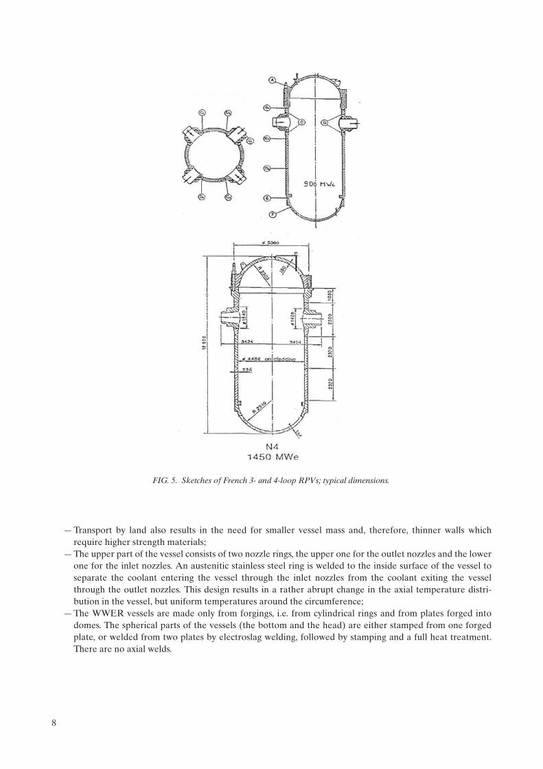
— Transport by land also results in the need for smaller vessel mass and, therefore, thinner walls which require higher strength materials;
— The upper part of the vessel consists of two nozzle rings, the upper one for the outlet nozzles and the lower one for the inlet nozzles. An austenitic stainless steel ring is welded to the inside surface of the vessel to separate the coolant entering the vessel through the inlet nozzles from the coolant exiting the vessel through the outlet nozzles. This design results in a rather abrupt change in the axial temperature distri-bution in the vessel, but uniform temperatures around the circumference;
— The WWER vessels are made only from forgings, i.e. from cylindrical rings and from plates forged into domes. The spherical parts of the vessels (the bottom and the head) are either stamped from one forged plate, or welded from two plates by electroslag welding, followed by stamping and a full heat treatment. There are no axial welds.
FIG. 5. Sketches of French 3- and 4-loop RPVs; typical dimensions.
8

FIG. 6. Comparison of PWR and BWR RPVs with the same output.
FIG. 7. WWER RPVs (split diagram).
9

The WWER inlet and outlet nozzles are not welded to the nozzle ring but they are either machined from a thicker forged ring, for the WWER-440 vessels, or forged in the hot stage from a thick forged ring for the WWER-1000 vessels.
2.2. RPV MATERIALS AND FABRICATION
2.2.1. Western RPVs
2.2.1.1. Materials
The Western LWR pressure vessels use different materials for the different components (shells, nozzles, flanges, studs, etc.). Moreover, the choices in the materials of construction changed as the PWR products evolved. For example, the Westinghouse designers specified American Society of Mechanical Engineers (ASME) SA 302 Grade B for the shell plates of earlier vessels and ASME SA 533 Grade B Class 1 for later vessels [2, 3]. Other vessel materials in common use include the ASME SA 508 Class 2 plate in the USA, 22NiMoCr37, and 20MnMoNi55 in Germany, and 16MnD5 in France. In addition to using plate products, all the NSSS vendors also use forgings in the construction of the shell courses. Table 4 lists the main ferritic materials used for LWR vessel construction over the years, and summarizes their chemical composition [4]. Table 5 lists the various materials used for the beltline region of LWR RPVs.
SA-302, Grade B is a manganese–molybdenum plate steel used for a number of vessels made through the mid-1960s. Its German designation is 20MnMo55. As commercial nuclear power evolved, the sizes of the vessels
TABLE 3. WWER PRESSURE VESSEL DESIGN PARAMETERS AND MATERIALS
ReactorWWER-440 WWER-1000
V-230 V-213 V-320
Mass (t) 215 320
Length (mm) 11 800 11 000
Outer diameter (mm)
— In cylindrical part 3 840 4 535
— In nozzle ring 3 980 4 660
Wall thickness (without cladding) (mm)
— In cylindrical part 140 193
— In nozzle ring 190 285
Number of nozzles 2 × 6a 2 × 6a + 2 × 3b 2 × 4a + 3b
Working pressure (MPa) 12.26 17.65
Design pressure (MPa) 3.7 19.7
Hydrotest pressure (MPa) 17.1 19.2c 24.6
Operating wall temperature (C) 265 288
Design wall temperature (C) 325 350
Vessel lifetime (a) 30 40 40
Cover mass (t) 50 90
Number of nozzles 37 + 18 61 + 30
a Primary nozzle.b Emergency core cooling system (ECCS) nozzle.c Test pressure was decreased later on to 17.2 MPa in Hungary and the Czech Republic, and 16.8 MPa in Slovakia.
10

TA
BL
E 4
. C
HE
MIC
AL
RE
QU
IRE
ME
NT
S (H
EA
T A
NA
LYSI
S) —
MA
IN F
ER
RIT
IC M
AT
ER
IAL
S F
OR
RE
AC
TO
R C
OM
PO
NE
NT
S IN
WE
STE
RN
C
OU
NT
RIE
S
Des
igna
tion
Ele
men
ts (
mas
s %
)
CSi
Mn
PS
Cr
Mo
Ni
VC
uA
lSn
NA
s
AST
M A
302
Bm
ax0.
250.
150.
301.
151.
50m
ax0.
035
max
0.04
00.
450.
60
AST
M A
336
, Cod
e C
ase
1236
0.19
0.25
0.15
0.35
1.10
1.30
max
0.03
5m
ax0.
035
max
0.35
0.50
0.60
0.40
0.50
ASM
E A
508
Cl 2
(19
71)
max
0.27
0.15
0.35
0.50
0.90
max
0.02
5m
ax0.
025
0.25
0.45
0.55
0.70
0.50
0.90
max
0.05
ASM
E A
533
GR
B (
1971
)m
ax0.
250.
150.
301.
151.
50m
ax0.
035
max
0.04
00.
450.
600.
400.
70
ASM
E A
508
Cl 2
(19
89)a
max
0.27
0.15
0.40
0.50
1.00
max
0..0
15m
ax0.
015
0.25
0.45
0.55
0.70
0.50
1.00
max
0.05
max
0.15
ASM
E A
508
Cl 3
(19
89)a
max
0.25
0.15
0.40
1.20
1.50
max
0.01
5m
ax0.
015
max
0.25
0.45
0.60
0.40
1.00
max
0.05
ASM
E A
533
Gr
B (
1989
)m
ax0.
250.
150.
401.
151.
50m
ax0.
035
max
0.04
00.
450.
600.
400.
70
16 M
nD5
RC
C-M
211
1bm
ax0.
220.
100.
301.
151.
60m
ax0.
02m
ax0.
012
max
0.25
0.43
0.57
0.50
0.80
max
0.
01m
ax
0.20
max
0.
040
18 M
nD5
RC
C-M
211
2 (1
988)
max
0.20
0.10
0.30
1.15
1.55
max
0.01
5m
ax0.
012
max
0.25
0.45
0.55
0.50
0.80
max
0.01
max
0.20
max
0.04
0
20 M
n M
o N
i 5 5
(19
83, 1
990)
c,d
0.17
0.23
0.15
0.30
1.20
1.50
max
0.01
2m
ax0.
008
max
0.20
0.40
0.55
0.50
0.80
max
0.02
max
0.12
e0.
010
0.04
0m
ax0.
011
max
0.01
3m
ax0.
036
22 N
i Mo
Cr
3 7
(199
1)f
0.17
0.23
0.15
0.35
0.50
1.00
max
0.01
2m
ax0.
008
0.25
0.50
max
0.60
0.60
1.20
gm
ax0.
02m
ax0.
12e
0.01
00.
050
max
0.01
1m
ax0.
013
max
0.03
6
aSu
pple
men
tary
Req
uire
men
t S 9
.1(2
) an
d S
9.2
for
A 5
08 C
l 2 a
nd A
508
Cl 3
.b
For
ging
s fo
r re
acto
r sh
ells
out
side
cor
e re
gion
. Res
tric
tion
s fo
r co
re r
egio
n
(RC
C-M
211
1): S
0
.008
, P
0.0
08, C
u
0.08
.c
VdT
ÜV
Mat
eria
l Spe
cifi
cati
on 4
01, I
ssue
198
3.
dK
TA
320
1.1
App
endi
x A
, Iss
ue 6
/90.
eC
u-C
onte
nt fo
r R
PV
(co
re r
egio
n) s
hall
be
0.10
%.
fA
ccor
ding
to S
iem
ens/
KW
U u
nder
con
side
rati
on o
f SR
10
(MP
A S
tutt
gart
).g
For
flan
ges
and
tube
she
ets
the
Ni c
onte
nt s
hall
be
1.40
%.
11

increased. For the greater wall thicknesses required, a material with greater ‘hardenability’ was necessary. The addition of nickel to SA-302, Grade B in amounts between 0.4 and 0.7 weight percent provided the necessary increased ‘hardenability’ to achieve the desired yield strength and high fracture toughness across the entire wall thickness. This steel was initially known as SA-302, Grade B (Ni modified).
Forging steels have also evolved since the mid-1950s. The SA-182 F1 modified material is a manganese–molybdenum–nickel steel used mostly for flanges and nozzles in the 1950s and 1960s. Another forging material used then was carbon–manganese–molybdenum steel, SA-336 F1. Large forgings of these materials had to undergo a cumbersome, expensive heat treatment to reduce hydrogen blistering. Eventually, these steels were replaced with a newer alloy that did not require this heat treatment. This newer alloy was first described as ASTM A366 Code Case 1236 but is now known as SA-508 Class 2 [5]. This steel has been widely used in ring forgings, flanges and nozzles.
It was introduced into Germany with the designation 22NiMoCr36 or 22NiMoCr37. With slight modifica-tions, this steel became the most important material for German reactors for a long time. Additionally, SA-508 Class 3 (20MnMoNi55 in Germany, and 16 MnD5 and 18MnD5 in France) is used in the fabrication of Western RPVs.
Although many materials are acceptable for reactor vessels according to Section II of the ASME code, the special considerations pertaining to fracture toughness and radiation effects effectively limit the basic materials currently acceptable in the USA for most parts of vessels to SA-533 Grade B Class 1, SA-508 Class 2 and SA-508 Class 3 [6].
The part of the vessel of primary concern with regard to age-related degradation is the core beltline — the region of shell material directly surrounding the effective height of the fuel element assemblies, plus an additional volume of shell material both below and above the active core, with an EOL fluence of more than 1021 m–2 (E > 1 MeV). This region is typically located in the intermediate and lower shells. The low alloy steels making up the beltline are subject to irradiation embrittlement that can lead to loss of fracture toughness. When early vessels were designed and constructed, only limited data existed about changes in material properties caused by radiation damage. Now it is known that the susceptibility of RPV steels is strongly affected by the presence of copper, nickel and phosphorus. Because operating vessels fabricated before 1972 contain relatively high levels of copper and phosphorus, irradiation damage becomes a major consideration for their continued operation.
The French have recently introduced the use of hollow ingots to make the beltline ring sections. The beltline material used in France is 16 MnD5. The chemical requirements for this material are listed in Table 4 along with the other Western materials. As a general rule, material with a tensile strength at room temperature above 700 MPa cannot be used for pressure boundaries. The other Western RPVs are designed with a minimum tensile strength of 350 MPa, as given in Table 6.
TABLE 5. MATERIALS USED FOR BELTLINE REGION OF LWR RPVs
Country Shells Austenitic cladding
USA SA302 GR BSA533 GR B, Class 1SA 508 Class 2SA 508 Class 3
TYPE 308L, 309LTYPE 304
France 16MnD5
Germany 20MnMoNi5522NiMoCr3 7
WWER-440 15Kh2MFA(A) Sv 07Kh25N13 — 1st layerSv 08Kh19N10G2B — 2nd layer
WWER-1000 15Kh2NMFA(A)
12
TA
BL
E 6
. G
UA
RA
NT
EE
D M
EC
HA
NIC
AL
PR
OP
ER
TIE
S O
F L
WR
RP
V M
AT
ER
IAL
S*
Mat
eria
l
20°C
350°
CT
k0
RT
ND
T
(°
C)
Rp0
.2
(MP
a)R
m
(MP
a) A
5
(%
)Z (%
)R
p0.2
(MP
a)R
m
(MP
a) A
5
(%)
Z (%)
15K
h2M
FA —
bas
e m
etal
431
519
14
5039
249
0 1
450
0
— A
/S w
eld
met
al39
253
9 1
450
373
490
12
4520
15K
h2N
MFA
— b
ase
met
al49
060
8 1
555
441
539
14
50–1
0
15K
h2N
MFA
A —
bas
e m
etal
490
608
15
5544
153
9 1
450
–25
— A
/S w
eld
met
al42
253
9 1
555
392
510
14
500
A 5
33-B
, Cl.1
345
551
18
—28
5—
——
–12
A 5
08, C
l.334
555
1 1
838
285
——
—–1
2
*R
p0.2 is
the
0.2%
off
set y
ield
str
engt
h, R
m is
the
ulti
mat
e te
nsile
str
engt
h, A
5 is
the
perc
ent t
otal
elo
ngat
ion,
Z is
the
perc
ent r
educ
tion
in a
rea
at fa
ilure
, Tk0
is th
e in
itia
l duc
tile
–br
ittl
e tr
ansi
tion
tem
pera
ture
and
RT
ND
T is
the
refe
renc
e te
mpe
ratu
re in
acc
orda
nce
wit
h Se
ctio
n II
I of
the
ASM
E b
oile
r an
d pr
essu
re v
esse
l cod
e.
13

2.2.1.2. Fabrication practices
Fabrication of RPVs has also been an evolving technology, and later vessels were fabricated using knowledge gained from surveillance programmes and more modern methods such as the use of large ring forgings to reduce the number of welds in the beltline [5, 7].
Large vessels are fabricated by two methods. In the first method, rolled and welded plates are used to form separate steel courses. Such a vessel has both longitudinal and circumferential weld seams (Fig. 8). In some older vessels designed before 1972, the longitudinal welds are of particular concern with regard to vessel integrity because they contain high levels of copper and phosphorous. In the second method, large ring forgings are used, as shown in Fig. 9. This method improves component reliability because of the lack of longitudinal welds. Weld seams are located to avoid intersection with nozzle penetration weldments.
Weldments within the beltline region were minimized once research showed that weld metal could be more sensitive to neutron radiation than base material and can have higher flaw density than base metals. In general, parts of the longitudinal shell course welds are within the beltline region when the RPV is fabricated using plate material. At least one circumferential weld is near, or marginally within, the beltline region when the RPVs are fabricated from either plates or ring forgings. Recently, nuclear steam supply system (NSSS) vendors are designing the RPV such that the beltline region does not contain any weldments. This is accomplished by utilizing very large ring forgings to fabricate the shell course.
FIG. 8. Expanded view of a PWR vessel showing individual pieces before welding. The cylindrical shell, circled region, is in the fuel zone and receives the highest neutron exposure.
14

FIG
. 9.
Dev
elop
men
t in
mat
eria
l lay
out o
f a
PW
RP
V/1
73-1
82.
15

The interior surfaces of the steel vessel, closure head and flange area are typically clad with stainless steel, usually Type 308 or 309. Cladding is used to prevent general corrosion by borated coolant and to minimize the build-up of corrosion products in the reactor coolant system. The cladding is variously applied in one or two layers by multiple-wire, single-wire or strip-cladding techniques; all are resistance welding processes. Some vessels have areas of Alloy 82 or 182 weld cladding where Alloy 600 components are welded to the vessel.
2.2.1.3. Welding
The welding processes used are mostly submerged arc and shielded metal arc. Before the early 1970s, copper-coated weld wire was used to improve the electrical contact in the welding process and to reduce corrosion during storage of the weld wire, hence the potential generation of hydrogen. When it was discovered that copper and phosphorus increased sensitivity to radiation embrittlement, RPV fabricators imposed strict limits on the percentage of copper and phosphorus in the welds as well as in plates [5, 8]. The use of copper-coated weld wire was subsequently eliminated due to the strict limits on the percentage of copper in the weld. The weld wire or stick electrodes were kept in storage in plastic bags and/or low temperature furnaces to eliminate the formation of moisture on the weld wire and electrodes.
For the circumferential welds, many weld passes and, consequently, a large volume of weld wire is needed. This becomes important when determining the properties of each individual weld in the beltline for sensitivity to neutron irradiation. For example, the chemistry of the weld (copper and nickel content) may vary through the thickness and around the circumference because of variations in the weld wire used in fabrication. Each weld in the vessel can be traced by the unique weld wire and flux lot combination used [7].
The sensitivity of welds to radiation can be inferred from the chemical composition. The degree of embrit-tlement (shift in transition temperature or decrease in upper shelf energy (USE)) is determined as a function of the chemical composition and the level of neutron exposure. Copper, nickel and phosphorus content in the weld are the most important elements from the standpoint of radiation damage. The embrittlement of high copper and high nickel welds plays a key role in the assessment of the significance of PTS [7].
2.2.2. WWER RPVs
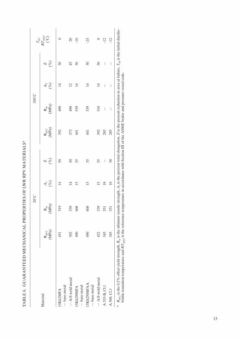
The WWER pressure vessel materials are listed in Table 5 and the major design parameters in Table 3. The guaranteed mechanical properties are listed in Table 6, the chemical compositions of the various WWER materials are listed in Table 7 and the allowable impurities in the beltline region are listed in Table 8. As indicated by the information in these tables, the WWER pressure vessel materials are basically different than the Western RPV materials. The Type 15Kh2MFA(A) material used for the WWER-440 pressure vessels contains 0.25 to 0.35 mass percent vanadium and very little nickel (maximum of 0.40 mass percent).
The Type 15Kh2NMFA(A) material used for the WWER-1000 pressure vessels contains 1.0 to 1.5 mass percent nickel (in welds up to 1.9 mass percent) and almost no vanadium. Material with vanadium alloying was first used in the former Soviet Union naval RPVs because the vanadium carbides make the material relatively resistant to thermal ageing, fine grained (tempered bainite) and strong. However, the Type 15Kh2MFA(A) material is more difficult to weld than nickel alloyed steels and requires very high preheating to avoid hot cracking. This became more of a problem for the large WWER-1000 pressure vessels and a material with nickel rather than vanadium alloying was chosen. The influence of vanadium on the susceptibility of those materials to radiation embrittlement was shown to be negligible.
Not all the WWER pressure vessels were covered by austenitic stainless steel cladding on their whole inner surface: only approximately half of the WWER-440/V-230 pressure vessels were clad. However, all of the WWER-440/V-213 and WWER-1000 pressure vessels were covered on the whole inner surface. The cladding was made by automatic strip welding under flux with two layers; the first layer is made of a Type 25 chromium/13 nickel non-stabilized austenitic material (Sv 07Kh25N13) and the second layer consists of at least three passes made of Type 18 chromium/10 nickel stabilized austenitic stainless steel (Sv 08Kh18N10G2B) to achieve a required total thickness of cladding equal to 8 ± 1 mm. Therefore, all the austenitic steels which are in contact with water coolant are stabilized.
The stabilized austenitic stainless steels for cladding contain an alloying element (niobium), which forms stable grain boundary carbides. This prevents chromium depletion along the grain boundaries and makes the
16

TA
BL
E 7
. C
HE
MIC
AL
CO
MP
OSI
TIO
N O
F W
WE
R F
OR
GIN
G A
ND
WE
LD
MA
TE
RIA
LS
(MA
SS %
)
Mat
eria
l C
Mn
Si
P S
Cr
Ni
Mo
V
WW
ER
-440
15K
h2M
FA0.
130.
180.
300.
600.
170.
37M
ax.
0.02
5M
ax.
0.02
52.
503.
00M
ax.
0.40
0.60
0.80
0.25
0.35
Subm
erge
d ar
c w
eld
Sv-1
0KhM
FT
+ A
N-4
20.
040.
120.
601.
300.
200.
60M
ax.
0.04
2M
ax.
0.03
51.
201.
80M
ax.
0.30
0.35
0.70
0.10
0.35
Subm
erge
d ar
c w
eld
Sv-1
0KhM
FT
+ A
N-4
2M0.
040.
120.
601.
300.
200.
60M
ax.
0.01
2M
ax.
0.01
51.
201.
80M
ax.
0.30
0.35
0.70
0.10
0.35
Ele
ctro
slag
wel
dSv
-13K
h2M
FT
+ O
F-6
0.11
0.16
0.40
0.70
0.17
0.35
Max
. 0.
030
Max
. 0.
030
1.40
2.50
—0.
400.
800.
170.
37
WW
ER
-100
015
Kh2
NM
FA0.
130.
180.
300.
600.
170.
37M
ax.
0.02
0M
ax.
0.02
01.
802.
301.
001.
500.
500.
70M
ax.
0.10
Subm
erge
d ar
c w
eld
Sv-1
2Kh2
N2M
A +
FC
-16
0.05
0.12
0.50
1.00
0.15
0.45
Max
. 0.
025
Max
. 0.
020
1.40
2.10
1.20
1.
900.
450.
75—
Subm
erge
d ar
c w
eld
Sv-1
2Kh2
N2M
A +
FC
-16A
0.05
0.12
0.50
1.00
0.15
0.45
Max
. 0.
012
Max
. 0.
015
1.40
2.10
1.20
1.
900.
450.
75—
TA
BL
E 8
. A
LL
OW
AB
LE
IM
PU
RIT
Y C
ON
TE
NT
IN
TH
E W
WE
R B
EL
TL
INE
MA
TE
RIA
LS
(MA
X. M
ASS
%)
Mat
eria
lP
S
Cu
As
SbSn
P +
Sb
+ S
nC
o
15K
h2M
FAA
0.01
20.
015
0.08
0.01
00.
005
0.00
50.
015
0.02
15K
h2N
MFA
A0.
010
0.01
20.
080.
010
0.00
50.
005
0.01
50.
02
A 5
33-B
, Cla
ss 1
0.01
20.
015
0.10
——
——
—
17

material immune to stress corrosion cracking. Unstabilized material was used for the first layer because the thermal expansion coefficient of that material is closer to the thermal expansion coefficient of the low alloy pressure vessel material.
The WWER vessel head contains penetrations with nozzles. The nozzles are welded to the vessel head from inside (buttering) and are protected by stainless steel sleeving (0Kh18N10T). A list of abbreviations used for nomenclature of WWER materials based on their chemical composition is given in Table 9.
2.3. DESIGN BASIS: CODES, REGULATIONS AND GUIDES
2.3.1. Western RPVs
The load restrictions on as-fabricated RPVs in various national standards and codes are generally based on Section III of the ASME Boiler and Pressure Vessel Code [9, 10]. The objective of designing and performing a stress analysis under the rules of Section III to the ASME Boiler and Pressure Vessel Code is to afford protection of life and property against ductile and brittle RPV failure. Some important differences exist in the RPV design requirements of certain other countries (e.g. Germany, France).
2.3.1.1. ASME Section III Design Basis
The USA reactor vessel has been designated as Safety Class 1, which requires more detailed analyses than Class 2 or 3 components. The rules for Class 1 vessel design are contained in Article NB-3000, which is divided into three sub-articles:
— NB-3100, General Design Rules;— NB-3200, Design by Analysis;— NB-3300, Vessel Design.
Sub-article NB-3100 deals with loading conditions specified by the owner (or his agent) in the form of an equipment specification. The specification identifies the design conditions and operating conditions (normal conditions, upset conditions, emergency conditions, faulted conditions and testing conditions).
Sub-article NB-3200 deals with the stresses and stress limits which must be considered for the analysis of the component. The methods of analysis and stress limits depend upon the category of loading conditions, i.e. the requirement for normal conditions are considerably more stringent than those for faulted conditions.
Sub-article NB-3300 gives special requirements that have to be met by Class 1 vessels. This article gives tentative thickness requirements for shells, reinforcement requirements for nozzles and recommendations for welding nozzles, for example.
Part 50 of the US Code of Federal Regulations, Title 10 (10 CFR 50) regulates the construction of nuclear power plants [11]. Section 10 CFR 50.55(a) defines the reactor vessel to be part of the reactor coolant boundary and requires that the vessel meet the requirements contained in the ASME Boiler and Pressure Vessel Code Section III for Class 1 vessels.
The German reactor vessel designs follow the German KTA standards for LWRs, published by the NUSS Commission. The KTA requirements are very similar to those in the ASME code regarding the definition of stress intensities and allowable stresses. However, considerable differences exist in the design requirements for USE and mid-thickness tensile and Charpy values, as well as for in-service inspections. The new German KTA also has a limit on the allowable fluence whereas the ASME code and the codes in a number of other countries do not.
The oldest French 3-loop plants were designed under ASME Section III, Appendix G [12]. The newer 4-loop plants are being designed under RCC-M B 3200, Appendix ZG [13]. The RCC-M B 3200 rules are similar to the rules in ASME Section III (however, the fabrication, welding, examination and QA rules are different) [14, 15].
18

2.3.2. WWER RPVs
The RPVs and primary system piping for all WWERs are safety related components and must be evaluated according to the former Soviet Codes and Rules [16–19]. With respect to the WWER RPVs, special analysis requirements are also provided for radiation embrittlement.
The Codes 18, 19 are divided into five parts:
— General Statements deals with the area of Code application and basic principles used in the Code;— Definitions give a full description of the most important operational parameters as well as parameters of
calculations;— Allowable stresses, strength and stability conditions;— Calculation of basic dimensions deals with the procedure for choosing the component wall thickness,
provides strength decrease coefficients and hole reinforcement values. Further, formulas for analysis of flange and bolting joints are also given;
— Validating calculations are the most important part of the Code. These detailed calculations contain rules for the classification of stresses as well as steps for stress determination.
Further, detailed calculations for different possible failure mechanisms are required and their procedures and criteria are given:
— Calculation of static strength;— Calculation of stability;— Calculation of cyclic strength (fatigue);— Calculation of resistance against brittle fracture;— Calculation of seismic effects;— Calculation of vibration strength (ultra-high-frequency fatigue).
A mandatory part of this Code contained in appendices is also a list of the materials (and their guaranteed properties) to be used for manufacturing the components of the NSSS, including the RPVs. These appendices also contain methods for the determination of the mechanical properties of these materials and some formulas for designing certain structural features (e.g. nozzles, closure, etc.) of the vessel, as well as typical equipment unit strength calculations.
TABLE 9. LIST OF ABBREVIATIONS USED IN WWER MATERIALS
Chemical elements
A High quality AA Very high quality/purity
U Improved
B Niobium F Vanadium
G Manganese Kh Chromium
M Molybdenum N Nickel
Sv Welding wire T Titanium
Beginning of the designation:
0 Lower than 0.1 mass% C 08 Mean value 0.08% C
15 Mean value 0.15% C
Centre of the designation:
Kh2 Mean value 2% Cr M Lower than 1% Mo
19

2.4. NDE REQUIREMENTS
2.4.1. Western RPVs
2.4.1.1. US requirements
RPVs in the USA are inspected in accordance with Section XI of the ASME Code [20]. There are three types of examinations used during in-service inspection: visual, surface and volumetric. The three types of in-service inspections are a carry-over from the pre-service inspection (PSI) that is required for the RPVs. Inspection plans are prepared for the PSI (if required), the first in-service inspection interval and subsequent in-service inspection intervals.
Each nuclear power plant follows a pre-service and in-service inspection programme based on selected intervals throughout the design life of the plant. The RPV inspection category is described in Table IWB 2500-1 of Section XI of the ASME Code, which details the inspection requirements. The in-service inspection intervals are determined in accordance with the schedule of Inspection Programme A of IWA-2410 or, optionally, Inspection Programme B of IWA-2420. Programme A is modelled on the traditional bi-modal distribution which is based on the expectation that most problems will be encountered either in the first few years of operation or late in plant service life. Programme B is modelled on the expectation that plant problems will be uniformly distributed with respect to time. For Programme B, 16% of the required inspections are to be completed in the third year, another 34% of the required inspections by the seventh year and the remainder by the tenth year of operation.
All shell, head, shell-to-flange, head-to-flange and nozzle-to-vessel welds, and repair welds (repair depth greater than 10% of wall thickness) in the beltline region must be subjected to a 100% volumetric examination during the first inspection interval (over 3 to 10 years). Successive inspection intervals also require 100% volumetric examination of all of these welds. The nozzle inside radius sections must all be subjected to a volumetric examination during each of the four inspection intervals. The external surfaces of 25% of the partial-penetration nozzle welds (Control Rod Drive Mechanism (CRDM) and instrumentation) must have a visual examination during each inspection interval (leading to total coverage of all nozzles).
All of the nozzle-to-safe end butt welds with dissimilar metals (i.e. the ferritic steel nozzle to stainless steel or Alloy 600 safe end weld) must be subjected to volumetric and surface examinations at each interval. All studs and threaded stud holes in the closure head need surface and volumetric examinations at each inspection interval. Any integrally welded attachments must have surface (or volumetric) inspections of their welds at each inspection interval.
Thus, the inspection plan for the RPV results in close monitoring of potential fatigue-crack formation and growth in all the relevant welds. Any additional monitoring and recording of transients is usually done in accordance with the plant technical specifications. Currently, qualification of test equipment, procedures and personnel on special real size mock-ups is required prior to ISI practically in all countries either in accordance with requirements of ASME Section XI or ENIQ (European Network for Inspection Qualification).
Many vessels in older plants were fabricated prior to Section XI of the ASME Code, hence these older plants did not undergo a PSI in accordance with the current rules. However, all of the RPVs in the USA have undergone in-service inspections in accordance with Section XI of the ASME Code. Additionally, the majority, if not all, the RPVs in the Western world have undergone in-service inspection in accordance with Section XI of the ASME Code or local rules similar to Section XI. Vessels fabricated before Section XI was issued have been reconciled to the requirements of Section XI using the results of a subsequent in-service inspection. Periodically, indications or flaws have been detected during an inspection. The indications or flaws have been evaluated in accordance with the acceptance standards of IWB-3500, Section XI, ASME Code. To date, all indications have been found acceptable by either the standards given in IWB-3500 or by analysis in accordance with Appendix A to Section XI of the ASME Code. There has never yet been an occasion when a PWR RPV had to have a flaw removed during service and undergo a weld repair.
20

2.4.1.2. German requirements
ISI in Germany dates back to the late 1960s, when a large research and development programme funded by the Federal Ministry for Research and Technology was launched. In 1972, a draft version for the In-service Inspection Guidelines of the Reactor Safety Commission was published and this document remained almost unchanged in the subsequent issues. This became the basis for the formulation of the German KTA 3201.4 Code [21], which today specifies the NDE requirements for ISI.
The ISI includes all welds, the nozzle radii, the control rod ligaments in the top head, the studs, nuts and threaded stud boreholes. The inspection intervals for the RPV are four years (for conventional vessels it is five years); however, the scope of an inspection may be subdivided and each part carried out separately during the four year period, e.g. each year at the refueling outage for BWRs.
The inspection technique usually used is ultrasonic testing (UT). The inspection method and techniques have to be chosen to detect all safety relevant flaws in the planes perpendicular to the main stresses, the planes parallel to the fusion lines of the welds and the planes perpendicular to the welds.
2.4.1.3. French requirements
The requirements for the French in-service inspection programmes are published in RSE-M [13]. The Code requires periodic hydrotests with acoustic emission monitoring during the hydrotests, NDE during the outages, a material surveillance programme, loose-parts (noise) monitoring during operation, leak detection during operation and fatigue monitoring. The Code specifies a complete programme including both the utility and regulatory agency inspections. Areas of the RPV that must be inspected include the beltline region of the shell, all the welds, the top and bottom heads, the nozzles, the penetrations, the control rod drive housings, the studs, the threaded holes and the supports.
One of the major differences between the French in-service inspection programme and the programmes in other countries is the hydrotesting. A hydrotest at 1.33 times the design pressure (22.4 MPa) is required after the RPV fabrication is completed. A hydrotest at 1.2 times the design pressure (20.4 MPa) is then performed after every ten years of operation.
The NDE techniques which are used in France include focused under water UT, radiography, visual exami-nations, tele-visual examinations under water, dye-penetrant tests, acoustic emission monitoring and eddy-current testing (ECT). UT of the welds generally covers the weld area plus about 50 mm of base metal on both sides of the weld. Base metal regions of the RPV shell subjected to fluences above 1022 m–2 are also inspected with ultrasonics, generally at a depth of 7 to 25 mm from the inside surface.
2.4.2. WWER RPVs
The WWER RPV in-service inspection is carried out at least every four years (30 000 h) of operation and includes NDE (visual, dye-penetrant, magnetic particle, ultrasonic and eddy-current) and hydraulic testing. Parts and sections of the reactor to be inspected, locations, and volume and periodicity are specified in the procedure. Surveillance specimen programmes are carried out independently every 4 years and are now being proposed for a 6/8 year cycle. A change to an eight year inspection interval for examination of the RPV inner surface is now under consideration by the regulatory bodies in the Czech Republic, Hungary and Slovakia.
Examination of the RPV base and weld metal in the zones with stress concentrations or high neutron flux, the cladding/base metal interface, the nozzle transition areas, sealing surfaces, outer and inner surfaces of the vessel bottom and top heads, bolts, nuts and threaded holes is obligatory. A special shielded cabin is used at some nuclear power plants for visual and dye-penetrant inspections from the inside of the RPV, as well as for the repair of any defects. The in-service inspection of the vessel head includes only a visual inspection (and sometimes also a dye-penetrant inspection) of sealing surfaces, welds and cladding, performed at the locations, which are accessible. Ultrasonic inspection of the circumferential weld is also performed.
The examination results are evaluated using the former Soviet procedure PK 1514-72 which was originally developed as a manufacturing defect rejection criterion. These standards and procedures have been approved by the Russian Federation’s regulatory body. Although they are not officially accepted by all the safety authorities responsible for WWER in-service inspections, they are used in general at most of the WWER plants since no
21

other procedure or standard for defect acceptance/rejection is available, except in Hungary, the Czech Republic and Slovakia where newly developed national procedures are applied. These procedures now serve as bases for the preparation of the “Unified Procedure for Lifetime Assessment of Components and Piping in WWER NPPs” within the European Community 5th Framework Programme project VERLIFE.
The ultrasonic examination equipment is calibrated using a flat-bottomed hole according to PK 1514-72. However, the most recent inspections in some plants have been performed using calibration methods similar to those used in the West.
3. EFFECTS OF IRRADIATION ON MECHANICAL PROPERTIES
3.1. INTRODUCTION
As discussed in Section 2, RPVs are designed and fabricated in accordance with consensus codes that are based on mechanical and physical properties of the steels used to construct the vessel. In the absence of radiation damage to the RPV, fracture of the vessel is difficult to postulate because the fracture toughness of the RPV in the unirradiated condition is generally excellent at and above room temperature. However, exposure to high energy neutrons can result in embrittlement of radiation-sensitive RPV materials. The degrading effects of neutron irradiation on carbon and low alloy pressure vessel steels have been recognized and investigated since the early 1950s (irradiation effects on the weld overlay stainless steel cladding on the inside surface of most RPVs will be briefly discussed).
In those steels at LWR operating temperatures (~260–300ºC), radiation damage is produced when neutrons of sufficient energy displace atoms that result in displacement cascades which produce large numbers of defects, both vacancies and interstitials. Although the inside surface of the RPV is exposed to neutrons of varying energies, the higher energy neutrons, those above about 0.5 MeV, produce the bulk of the damage (discussed in Section 4). In a typical LWR, the flux of such high energy neutrons is from about 1013 to 1016 n · m–2 · s–1. For Western LWRs, neutron energies greater than 1 MeV are used for correlations, while 0.5 MeV is used as the threshold for WWERs. At RPV temperatures, residual vacancies and interstitials diffuse relatively long distances. The mobility of small interstitial clusters and the dissolution of vacancy clusters by vacancy emission tend to heal the crystal lattice, but a small percentage of these defects may survive. A detailed description of the mechanisms of radiation damage and the formation of various types of defects, clusters, precipitates, etc. is presented in Section 4.
Regarding their effects on material properties, these ultrafine (nanometer) microstructural features act as effective obstacles and require increased stress to move dislocations through or around them. As radiation exposure increases, the number of ultrafine scale obstacles increases and higher stresses are required for dislocation motion with a resulting increase in the yield strength of the material. The yield strength increases result in higher temperatures required to keep the yield strength below the cleavage fracture strength, especially near the tip of a crack where large stress and strain concentrations exist. Thus, the fracture toughness transition temperature is increased as is the measure used to describe the radiation-induced embrittlement.
For some steels, non-hardening embrittlement can be caused by radiation-induced solute segregation such as phosphorus segregation at grain boundaries. This type of embrittlement can manifest as intergranular (grain boundary) fracture, rather than the usual transgranular cleavage fracture. Copper has the greatest effect on irradiation sensitivity, but nickel and phosphorus are also strong contributors. Evidence also points to contribu-tions of vanadium, manganese and silicon. Most of the irradiation predictive formulas around the world variously include copper, nickel and phosphorus contents.
Thus, as the steel becomes embrittled, the concomitant changes in strength and toughness with temperature must be known so the RPV can be operated within the design envelope. The synergistic effects of neutron fluence, flux and spectrum, the irradiation temperature, and the chemical composition and micro-structure of the steel must be understood to allow for reductions in uncertainties associated with the
22

development of predictive models. In addition to the basic strength and toughness properties, other properties are often determined, especially within research programmes, to provide information relevant to a deeper understanding of material behaviour.
Some of the more common mechanical properties are provided in Table 10. As shown, some tests use a blunt notch, while others use a sharp crack to determine material resistance to crack initiation, crack propagation or both. Moreover, tests are conducted under either quasi-static (slow) loading or dynamic (fast) loading conditions. Of all these tests, the most commonly used test is the Charpy V-notch (CVN) impact test. In addition to those mechanical properties, there are common reference fracture toughness indices used for RPV steels. These are given in Table 11. The nil ductility transition (NDT) temperature is listed in both tables because it is determined as a measured value but is also used as an index. These indices are used in various ways to normalize fracture toughness of RPV steels. Further details of the various tests and indices, as well as examples of results, are discussed in subsequent sections.
In some investigations, changes in physical properties such as thermal conductivity have been determined to investigate the potential effects of such changes on the RPV behaviour under accident scenarios such as PTS. Changes in the physical properties of RPV steels are minimal.
The literature on irradiation effects in RPV steels is considerable and a detailed presentation of that literature is beyond the scope of this book. Previous IAEA reviews of this subject are referenced in Section 1 and the reader is referred to those reviews for extensive discussions of the early work on effects of irradiation on mechanical properties. This section provides a brief overview of the important mechanical properties of RPV steels and the effects of neutron irradiation on those properties.
TABLE 10. COMMON MECHANICAL PROPERTIES FOR RPV STEELS
Property Test rate MeasurementNotch type
Test method examples
Strengthyieldultimate
Quasi-static Rp0.2
Rm
None Tensile test; e.g. ASTM E 8, EN 10002-1, EN 10045-1
Notch impact toughness energyLateral expansion% shear fracture
Dynamic T41J, Tk, T68J, USET0.89mm
T50%
Blunt Charpy V-notch (CVN) impact test; e.g. ASTM E 23, EN ISO 148. Obtain curve fit to data versus test temperature, determine various transition temperature indices, e.g. T41J and USE.Initiation and propagation test
Nil ductility transition temperature
Dynamic TNDT Blunt changes to sharp
Drop-weight specimen test; e.g. ASTM E 208Uses brittle weld crack starter on test specimenPropagation test
Fracture toughnesscleavage fractureDuctile fracture
Quasi-staticDynamicQuasi-staticDynamic
KIc, KJc,KId, KJd,JIc, J-RJId
Sharp crack produced by fatigue
Fracture toughness test of fatigue pre-cracked specimen; e.g. ASTM: E 399, E 1820, E 1921, ESIS P2-91D, ISO 12135, BS 7448, EN ISO 12737.J-R test is propagation test, others are initiation tests
Crack-arrest toughness Quasi-static load then dynamic propagation
KIa Blunt changes to sharp
Crack-arrest test with notched specimen; e.g. ASTM E 1221Propagation test
Hardness H None Hardness test by indentation; micro-hardness by, e.g. ASTM E 92, EN ISO 6507-1
23

3.2. BRIEF DESCRIPTION OF FAILURE MODES
As stated earlier, the low alloy RPV steels are ferritic steels that exhibit the classic ductile-to-brittle transition behaviour with decreasing temperature. In the low toughness region, transgranular cleavage is the failure mode, while ductile rupture (shear fracture) is the failure mode in the high toughness region. As temperature increases from the low to high toughness region, the cleavage fracture probability decreases and the ductile rupture probability increases. As will be seen in subsequent sections, neutron irradiation tends to increase the temperature at which this transition occurs and tends to decrease the ductile toughness. Figure 10 shows prototypic scanning electron microscope fractographs indexed to the various regions of a Charpy impact toughness curve. As can be seen, increasing test temperatures result in increasing ductility and, as a result, less transgranular cleavage fracture, with failure by 100% ductile rupture in the so-called USE region. The two specimens with 30 and 75% ductility experience ductile failure in the initial part of the fracture event, followed
TABLE 11. REFERENCE FRACTURE TOUGHNESS INDICES
Index Notation Description
Nil ductility transition temperature (NDTT)
TNDT Drop-weight test by ASTM E-208 to determine temperature above which material toughness results in arrest of brittle propagating crack.
Reference temperature NDT RTNDT Combination of drop-weight NDTT and CVN impact tests by ASME Code (see Sections 3 and 5 for additional details).
Reference fracture toughness temperature T0
T0 Quasi-static fracture toughness testing by ASTM E 1921 to measure cleavage initiation fracture toughness, KJc, under elastic–plastic conditions of minimum no. of specimens. Master Curve is fitted to results to get T0 at 100 MPam for results size adjusted to 1T specimen size.
Reference temperature RTT0 RTT0 Specified in ASME Code Cases N-629 and N-631 as RTT0 = T0 + 35ºF (19.4ºC) and used in place of RTNDT to index the ASME KIc curve.
Critical temperature of brittlenessTk
Tk Specified in the Russian Code as a reference transition temperature based on the temperature at a specified Charpy impact energy; the energy level is specified based on the material yield strength, Rp0.2 (see Section 5 for additional details).
FIG. 10. Pressure vessel steels exhibit a rapid transition from brittle-to-ductile behaviour by measuring the energy to break a CVN specimen under impact loading.
24

by transgranular cleavage (the ‘shiny’ portion seen on the fracture surface), with ductile failure as the final part of the fracture event. Thus, as the test temperature decreases, this behaviour of RPV steels typifies the description of the ductile-to-brittle transition exhibited by ferritic steels. This will be discussed in more detail later in this section.
Although transgranular cleavage is the predominant mode of brittle fracture in RPV steels, solute (e.g. phosphorus) segregation to grain boundaries can result in another type of brittle fracture known as intergranular (grain boundary) fracture. Figures 11(a) and 11(b) show examples of transgranular and intergranular fracture, respectively, as viewed in a scanning electron microscope.
3.3. EXPERIMENTAL PROCEDURES
This section provides only a basic description of these procedures; various references are provided for the reader who desires a deeper understanding.
3.3.1. Testing techniques
As given in Table 10, all the mechanical properties to be discussed are generally determined by conducting tests in accordance with consensus standards. In the USA, most of the standards used are published by the American Society for Testing and Materials (ASTM). There are, of course, many other standards organizations around the world in various countries that publish procedures and standards similar to those of the ASTM that are also mostly accepted as European Standards (EN).
3.3.1.1. Tensile test
Figure 12 shows an example of a tensile test specimen and a diagram of a typical tensile test result with which yield (generally at 0.2% strain) and ultimate tensile strengths are determined.
Load is generally measured with a load cell mounted on the test machine while strain is measured with an extensometer mounted on the specimen, although the test machine displacement is often used when accurate measurements of strain are not required. If a determination of the elastic modulus is desired, an extensometer with very high resolution is required. Specimens of various shapes and sizes can be used and the applicable testing standards provide details of the test procedures and methods of analysis. In the USA, ASTM E-8 [22] is the test standard most often used. Generally, the quasi-static tensile properties are determined, although a very rapid loading rate can be used to determine dynamic tensile properties.
FIG. 11. Scanning electron microscope fractographs of prototypic (a) transgranular and (b) intergranular fracture, in an RPV steel.
25

3.3.1.2. Charpy V-notch impact test
Figure 13 shows a schematic of the pendulum impact machine1, and plots of energy, percent shear fracture and lateral expansion versus temperature data with curve fits for a typical RPV steel. Although not universal, it is rather common practice to fit Charpy impact energy and lateral expansion versus temperature data with a hyperbolic tangent function, often with the ‘lower shelf’ fixed at some predetermined value, for example, 2.7 J or 0 mm [23].
In the USA and many Western countries, the level of 30 ft-lb (41 J) is typically used as an index transition temperature. In the Russian Federation and other countries that operate WWER plants, the transition temperature is dependent on material strength (see Section 5), with 47 J being the most commonly referenced index temperature [24]. In the USA and some other Western countries, ASTM E-23 [25] is the test standard used for CVN impact testing, while EN ISO 148 [26] is common in Europe and some Western countries. Reference [27] discusses comparisons of tests with the two standards.
In addition to the standard specimen configuration (10 mm × 10 mm × 55 mm with a 2 mm deep notch), there are a number of other types of impact specimens that have been used over the years to characterize impact toughness; for modern RPV steels, that specimen has become essentially universal for use of full-size specimens. There are a number of variations in the geometrical relationships of the specimen, however, when using subsize specimens. So-called half-size, third-size, etc. specimens have been used to characterize the toughness of RPV steels, with much of the early work accomplished in Russian Federation through the use of correlations with full-size specimens [28]. Other studies have also been conducted with the development of many different correla-tions [29], but no single consensus correlation has been universally adopted. There is a draft practice under development within the ASTM. In the case of limited material availability, the technique of specimen reconsti-tution has been utilized, with the ASTM Standard Practice E-1253 [30] being the most commonly used procedure.
3.3.1.3. Drop-weight test
Figure 14 [31] shows a drop-weight specimen, a schematic of the drop test system and examples of drop-weight test results for a typical RPV steel.
ASTM E 208 [32] describes three specimen sizes for determination of the NDT temperature, but the smallest specimen (5/8 in (15.875 mm) thick) is most commonly used. The specimen incorporates a notched brittle weld bead to serve as a crack starter such that, when the specimen is impacted, a dynamic propagating
1 Schematic diagrams courtesy of Prof. G. R. Odette, University of California, Santa Barbara, CA, USA.
FIG. 12. Schematic diagram of a typical tensile test result with which yield (generally at 0.2% strain) and ultimate tensile strengths are determined.
26

FIG. 13. Schematic diagrams of (a) pendulum-type impact machine, CVN specimen and effect of irradiation on Charpy impact energy, and plots of (b) energy, (c) % shear fracture and (d) lateral expansion versus temperature data with curve fits for a typical RPV steel.
27

FIG. 14. A schematic diagram of a typical drop test system, example of test results and examples of broken samples are shown in (a). (b) depicts the placement of the specimen on the supports and examples of crack propagation defining break versus no-break and (c) shows photographs of tested specimens heat tinted to show the progression of crack propagation as test tempera-ture decreases for a typical RPV steel.
28

crack is presented to the test material. The apparatus and procedures are designed to load the specimen to yield stress at the outer surface through a combination of drop weight, drop height and prescribed specimen deflection. The test is used to determine that temperature at and below which brittle fracture occurs even from small flaws, but above which plasticity is sufficient to preclude brittle fracture. The test is a qualitative crack-arrest test in that a specimen that experiences crack propagation to at least one edge of the specimen is labeled a ‘break’, while one that does not is labeled a ‘no-break’. The NDT temperature is determined when two no-break tests are obtained at 10F (5C) above that of a break test. The NDT temperature is not a material property, rather it is an index temperature used primarily as a normalization tool to compare different steels, or a specific heat of steel in different conditions and to provide a qualitative correlative parameter. This type of test is not applied to WWER RPV steels, largely due to highly variable results obtained during early experiments [33].
The Reference Temperature NDT, RTNDT, is also an index temperature used as a normalization tool. RTNDT
is determined according to procedures outlined in the ASME Boiler and Pressure Vessel Code [33] and is a combination of the NDT temperature and Charpy impact test results. Briefly, the RTNDT is the higher of either the NDT temperature or T50 — 60ºF (33ºC), where T50 is the temperature at which three Charpy impact specimens achieve energy and lateral expansion values of at least 50 ft-lb (68 J) and 0.035 in (0.89 mm), respectively. A more detailed discussion of this reference temperature can be found in Section 5. Similarly, for WWER RPVs, the CVN based temperature called the critical temperature of brittleness, Tk, is used as a reference temperature. Determina-tions of Tk0 for the unirradiated condition and Tk for the irradiated condition are discussed in Section 5.
3.3.1.4. Fracture toughness test: brittle fracture, linear elastic
As shown in Tables 10 and 11, fracture toughness tests are conducted to measure various fracture and fracture related parameters. Whereas toughness tests with notched impact specimens provide a qualitative measure of toughness, fatigue pre-cracked specimens provide quantitative measures for use in predicting critical crack sizes and allowable stresses in the presence of defects of known sizes. The most common parameter of fracture mechanics is the plane-strain fracture toughness, defined as “the crack extension resistance under conditions of crack-tip plane strain”. The plane strain fracture toughness is considered a material property and is designated KIc, the critical value of the mode I (opening mode) stress-intensity factor determined in accordance with ASTM Test Method E399 [34]. Figure 15 shows the two most common specimen types, the compact specimen and the three-point bend specimen, used to measure fracture toughness.
The figure also shows a schematic diagram of load versus displacement plots describing the determination of a linear-elastic fracture mechanics (LEFM) test. The determination of KIc is dependent on testing the material under conditions in which it exhibits essentially linear elastic behaviour indicative of a plastic zone that is very small relative to flaw size and specimen dimensions, the domain of LEFM. The equations for the compact specimen and three-point bend specimen are as follows:
Compact specimen: , (1)
three-point bend specimen: KQ = P S f(a/W)/(B W1.5) (2)
where KQ is a provisional value of KIc, P is load, a is crack depth, W is specimen width and B is specimen thickness. The test practice specifies various criteria for the KIc measurement to be ‘valid’, but the dominant criterion is that based on the size of the plastic zone relative to the specimen thickness and crack length, and is determined by the relationship:
if 2.5 (KQ/YS)2 B, a, (3)
then KQ = KIc.
where YS is the 0.2% offset yield strength at the test temperature.
K P fa
WB WQ = ¥ Ê
ËÁˆ¯∏ ¥ 0 5.
29

LEFM is valid only for the case of a very small, contained plastic zone (surrounded by a large elastic region) ahead of the crack tip. The basic principle is that unstable fracture will occur when the applied stress intensity factor exceeds the plane-strain fracture toughness, i.e. KI > KIc.
Similarly, KId represents the plane-strain fracture toughness under high-rate or dynamic loading conditions. One of the primary constraints in the determination of KIc or KId is the need for large specimens. To
FIG. 15. The two most common specimen types used to measure fracture toughness are (a) the three-point bend specimen shown schematically, and (b) the compact specimen shown mounted in grips with a clip gage extensometer attached. The figure also shows a schematic diagram of various types of load versus displacement plots describing the determination of an LEFM test.
30

obtain the nearly tri-tensile plane-strain conditions required for a ‘valid’ measurement of KIc for RPV steels over the range of fracture toughness values of interest, specimens as large as 300 mm thick are required. More than three decades ago, compact specimens of various sizes to about 280 mm were fabricated from a heavy-section plate of a typical Western RPV steel and tested to obtain valid KIc measurements. Figure 16(a) shows the results and demonstrates the need for increasing specimen size with increasing test temperature to obtain a valid plane-strain measurement.
Subsequently, large specimens of 11 different heats of Western RPV steels were tested and the results were used to construct a lower bound curve of KIc versus temperature normalized to the RTNDT, as shown in Fig. 16(b). A similar construction was used to determine a lower bound curve for results from KId and KIa tests; this curve is denoted the reference fracture toughness, KIR, shown later in discussion of crack-arrest toughness, KIa. Testing of such large specimens is prohibitive except for special research applications, thus, providing a major driving force for the developments in elastic–plastic fracture mechanics (EPFM).
3.3.1.5. Fracture toughness test: ductile fracture, elastic–plastic
When large deformations occur, the precepts of LEFM are violated and nonlinear fracture mechanics methods must be utilized to evaluate structural integrity. Because fracture stress increases with decreasing flaw size, fracture toughness specimens of practical size for routine use often experience yielding before fracture. Methods are needed to characterize the material fracture resistance with a small specimen for application to a large structure: thus, the question of scaling from a specimen with a large plastic zone to a structure with a small plastic zone is required. Five of the techniques that have been extensively discussed are: (i) crack-opening displacement (COD), (ii) R-curve analysis, (iii) equivalent energy, (iv) local approach and (v) J-integral.
The most widely used EPFM criterion is the J-integral, first introduced by Rice in 1968 and first incorpo-rated in a consensus testing standard in 1981, i.e. ASTM E813 [35]. It is a line integral that describes the stress–strain field at the tip of a crack by assuming a path of integration far from the crack tip but lying completely inside the body.
It provides a means of analysing the far-field region to infer the behaviour of the near-field region which may experience substantial plastic deformation. Figure 17(a) shows a schematic for a J-integral contour at a crack tip [31].
On a physical basis, J may be interpreted as the rate of change of potential energy per unit crack length between two bodies identically loaded:
J = (dU/da), (4)
where U is displacement and a is crack length. For slightly different crack lengths in otherwise identical specimens, Fig. 17(b) [31] schematically shows the nonlinear energy release rate concept leading to the calculation of the work necessary to extend the crack. Further developments in the field resulted in a method for evaluating J from single load versus load point displacement test results to make single test evaluations of J for many specimen configurations practicable. For the linear case, J is related to K and G (energy release rate) by:
J = G = (K2/E), (5)
where E is Young’s Modulus. For plane-strain situations, the relationship is often expressed as:
J = G = [(K2/E(1 2)], (6)
where is Poisson’s ratio. For most structural steels, the difference between Eqs (5) and (6) is less than 10%. A review of the considerable body of work in this area is beyond the scope of this report.
For application of the deformation theory of plasticity to any linear-elastic or elastic–plastic material, the J-integral has been shown to be independent of the contour path. Since its initial development, the J-integral has been developed into a relatively mature and accepted fracture criterion, as evidenced by the development of various test standards to measure the resistance of a material to onset of ductile crack extension, JIc, the description of a J-resistance (J-R) curve, and the value of J at the onset of cleavage fracture, Jc. Figure 18 from
31

FIG. 16. Large compact specimens of one heat of RPV steel were tested and the results in (a) demonstrate the need for increasing specimen size with increasing test temperature to obtain a valid plane-strain measurement, while results from 11 different heats of steel were used to construct a lower bound curve of KIc versus temperature normalized to the RTNDT, as shown in (b).
32

ASTM E1820 [36] shows a typical load versus load–line displacement trace from a single specimen unloading compliance test, the J versus crack extension plot (resulting from analysis of the load–displacement trace) used to determine the J-R curve, the JIc, and a dimensionless parameter that describes the material resistance to stable crack growth, the tearing modulus (a dimensionless parameter based on the J–R curve slope dJ/da). As with LEFM conditions, the EPFM parameters of ductile fracture toughness resistance are also dependent on specimen size. According to ASTM E 1820, a valid JIc can be determined if the measured provisional value of JQ
satisfies the criteria:
B and bo 20 JQ/Y, (7)
where bo is the initial ligament (mm) and Y is the 0.2% offset yield strength (MPa).There are similar criteria placed upon the amount of crack growth exhibited by the specimen, such that a
combination of J and crack growth limits can be described by a ‘box’ that the test parameters must stay within to be considered valid measurements, also shown in Fig. 18(c). The values of JIc and tearing modulus can then be used in an analysis to predict ductile crack initiation and ductile crack extension behaviour of the RPV.
FIG. 17. Schematic diagrams showing (a) a J integral contour at a crack tip and (b) nonlinear energy release rate. These diagrams present the concept of the J-integral, a line integral used to determine the work necessary for incremental ductile crack growth (from Ref. [31]).
33
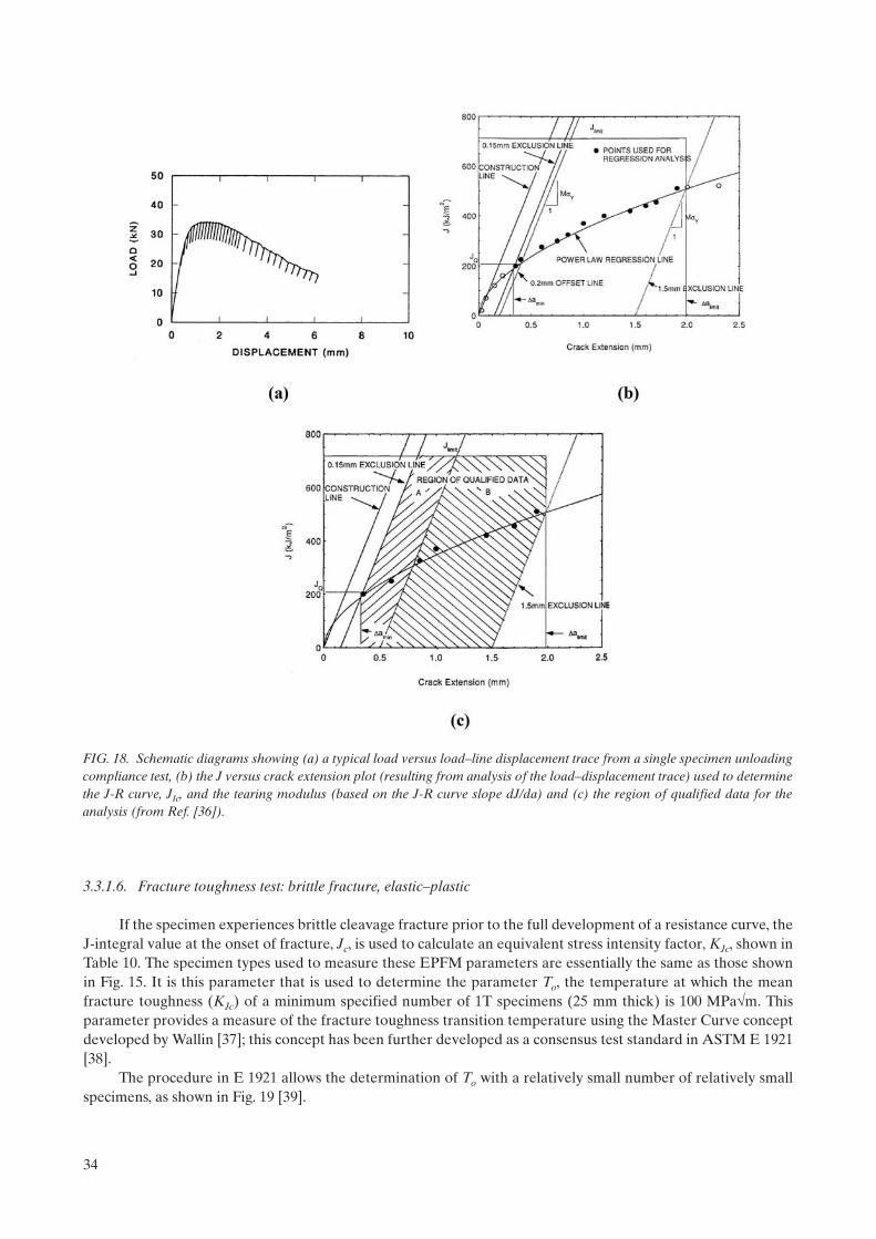
3.3.1.6. Fracture toughness test: brittle fracture, elastic–plastic
If the specimen experiences brittle cleavage fracture prior to the full development of a resistance curve, the J-integral value at the onset of fracture, Jc, is used to calculate an equivalent stress intensity factor, KJc, shown in Table 10. The specimen types used to measure these EPFM parameters are essentially the same as those shown in Fig. 15. It is this parameter that is used to determine the parameter To, the temperature at which the mean fracture toughness (KJc) of a minimum specified number of 1T specimens (25 mm thick) is 100 MPam. This parameter provides a measure of the fracture toughness transition temperature using the Master Curve concept developed by Wallin [37]; this concept has been further developed as a consensus test standard in ASTM E 1921 [38].
The procedure in E 1921 allows the determination of To with a relatively small number of relatively small specimens, as shown in Fig. 19 [39].
FIG. 18. Schematic diagrams showing (a) a typical load versus load–line displacement trace from a single specimen unloading compliance test, (b) the J versus crack extension plot (resulting from analysis of the load–displacement trace) used to determine the J-R curve, JIc, and the tearing modulus (based on the J-R curve slope dJ/da) and (c) the region of qualified data for the analysis (from Ref. [36]).
34

The figure shows the KJc test results from six 0.5T compact specimens of an RPV weld metal, the fracture toughness Master Curve fit to the results after adjustment to 1T specimen size and the same curve compared with the fracture toughness results from larger specimens of the same weld metal. The figure also shows that the 5% tolerance bound provides a good representation of a bounding curve for the results. Reference [40] is the background document for the development of E 1921. As with the RTNDT, the parameter To can be used as a reference temperature to normalize the fracture toughness of RPV steels. Figures 20(a), 20(b) and 20(c) [41]
FIG. 19. The test procedure in E 1921 allows the determination of To with a relatively small number of relatively small specimens. The results from (a) six small (0.5T) specimens tested at one temperature provide an excellent characterization of the results from (b), a large number of specimens up to 4T size.
35

36

show the same fracture toughness data as in Fig. 16, but demonstrate that, although these are valid plane-strain KIc data from very large specimens, the Master Curve provides a good representation of the results when normalized to 1T specimen size.
Figure 20(d) shows that because the RTNDT is determined from drop-weight and Charpy tests, there is no consistent relationship between that parameter and To, which is a parameter determined directly from fracture toughness results. As shown in Fig. 21(a), the Master Curve describes well a large amount of data for Western steels [42]. Likewise, Fig. 21(b) shows a similar comparison for the RPV steels of WWER-1000 reactors [43].
To overcome the lack of correlation between To and RTNDT, the Pressure Vessel Research Council in the USA developed a separate reference temperature based on To [43]. This reference temperature, RTTo, was developed by determination of a temperature offset to To that would bound the fracture toughness data similar to that of the KIc curve in the ASME Code and has been incorporated into the ASME Code by Code Cases N-629 [44] and N-631 [45]. Thus, in this scheme, RTTo = To + 19.4ºC (35ºF), and the ASME curve is used with RTTo
as the reference temperature instead of RTNDT. Other reference temperatures using To have been developed for WWER steels. For example, the TACIS
IRLA project has defined different values of RTTo as follows [46]:
— WWER-1000 base metals: RTTO = To + 10C;— WWER-1000 welds and WWER-440 all: RTTo = To.
Other reference temperature developments based on To and the Master Curve are underway in the Czech Republic, Slovakia, the Russian Federation and Finland. Additional discussions are presented in Sections 5 and 6.
3.3.1.7. Fracture toughness: other methods
In addition to the J-integral based procedures for EPFM described above, other procedures have been developed concurrently and some of them, such as the crack tip opening displacement [47] and the Equivalent
FIG. 20. The Master Curve fitted to all the individual sets of data shown in Fig. 16 shows that in (a), (b) and (c) although these are valid plane-strain KIc data, the Master Curve provides a good representation of the results, and (d) shows that there is no consistent relationship between RTNDT and To.
37

Energy Method [48, 49] have been standardized. Additionally, the J-integral concept is used in various ways in different standards to determine ductile fracture toughness. For example, the method to determine the value of ductile initiation fracture toughness in Japan combines the J-integral unloading compliance test procedure with examination of the tested specimen fracture surface in a scanning electron microscope to measure the extent of crack tip blunting.
FIG. 21. Plots of fracture toughness data for (a) Western RPV steels and (b) WWER-1000 RPV steels, showing that data from both types of steels are well described by the Master Curve.
38

3.3.1.8. Crack-arrest toughness test
The parameter KIa describes the ability of the material to arrest an unstable propagating crack. Fig. 22 shows a schematic diagram of the loading procedure [31]. The crack-arrest test is conducted by loading the specimen through a wedge-loading technique with a displacement gage used to measurement specimen displacement across the notch. In this case, however, the value of KIa is calculated with displacement values as opposed to load values. As with KIc, results of crack-arrest tests were used to construct a lower bound curve of KIa versus temperature normalized to the RTNDT, as shown in Fig. 23 [61]. In the ASME Code, a reference fracture toughness curve, the KIR curve, is the same as the KIa curve but describes a lower bound curve to both
FIG. 22. Schematic diagram showing the loading procedure and test system for measuring crack-arrest toughness (from Ref. [50]).
FIG. 23. Plot of crack-arrest, KIa, and dynamic fracture toughness, KId, results used to construct a lower bound curve versus temperature normalized to the RTNDT, designated the KIR curve. The KIR curve is the same as the KIa curve (from Ref. [61]).
39

KId and KIa data, both of which are included in Fig. 23. At the time of construction of those curves (1972), there was no standard test for measuring KIa, yet tests were performed and the results incorporated into the ASME Code. In the mid-1980s, a cooperative test programme was conducted and resulted in the development of ASTM test standard E 1221 [50]. To date, this is the only published consensus standard for crack-arrest testing. As with the crack initiation fracture test standards, E 1221 also prescribes specimen size and crack size criteria that must be satisfied to obtain a valid KIa measurement.
3.3.1.9. Non-destructive tests
The use of NDE techniques has long been a goal for determination of the state of fracture toughness in an irradiated RPV. Ultrasonic attenuation, Mössbauer spectroscopy, positron annihilation, eddy current, supercon-ducting quantum interference device (SQUID), magnetomechanical acoustic emission, Barkhausen noise, etc. have been investigated with varying degrees of success, although the advent of nonlinear techniques for analysis of the signals holds more promise than the standard linear methods. This section will not discuss the topic in any detailed manner, but it is noted that the state of the art for use of NDE remains elusive [51]. There are some relatively new techniques, however, that hold promise for a more reliable indicator of the state of the irradiated steel. The thermo-electric power (TEP) technique, for example, has seen increasing attention in the past decade. TEP measures electrical resistivity and may be more sensitive to the nano-scale features that evolve in the irradiated microstructure [52, 53]. In addition to NDE techniques, there are quasi non-destructive techniques that have been investigated. One example is the automated ball indentation (ABI) test [54]. This technique uses a ball indenter and a sensitive linear–variable displacement transducer (LVDT) to obtain a load–displacement trace from which a true stress versus true plastic strain curve is obtained. The curve is then analysed using various correlative parameters to estimate the yield strength of the material. In the case of irradiation-induced embrittlement, correlations between changes in yield strength and TT, the Charpy impact transition temper-ature, can be estimated for the irradiated steel.
3.3.2. Irradiation experiments
Practically all commercial LWRs include a surveillance programme to monitor irradiation-induced changes in mechanical properties, especially toughness, of critical RPV materials. In the USA, for example, standard CVN impact specimens (10 mm × 10 mm) and tensile specimens are required [55]; fracture toughness specimens are not required but are included by some nuclear power plants. As many of the older plants approach their original design or licence lives and most or all of the available surveillance specimens have been expended, reconstituted CVN or subsize CVN specimens may be used to allow for continued operation. A detailed discussion of surveillance programmes is presented in Section 5.
There are a variety of nuclear reactors that are used to conduct irradiation experiments on RPV steels. Although a description of test reactors is beyond the scope of this book, a few observations are appropriate. The material test reactors most generally used for RPV steel experiments are open pool-type reactors with power levels ranging from about 2 to 30 MW (t). Typically, the pool temperature is about 50C; thus, to irradiate test specimens under conditions prototypic of those in a power reactor it is necessary to place the specimens in capsules designed to heat the specimens. Neutron dosimeters are incorporated in the capsules to monitor the neutron fluence.
The quality of such capsules is extremely important to successful experiments because, as discussed in more detail in later sections, the effects of irradiation on RPV steels are dependent on temperature, neutron flux and neutron fluence. To ascertain such effects, various experiments are specially designed to vary the parameters in ways that attempt to eliminate confounding effects through the conduct of single variable experiments. For example, irradiating a specific heat of steel at different temperatures but constant flux and fluence can provide information regarding irradiation temperature. When considering the additional variables associated with chemical composition, microstructure and fabrication practices, the single-variable experiments needed to sort out the effects can become quite daunting. Nonetheless, as discussed in this and other sections, a considerable body of information has been developed to shed considerable light on the problem.
Although most irradiation experiments for research programmes are conducted in material test reactors, commercial power reactors are sometimes used. In this case, because the water temperature is appropriate to
40

power reactors, enclosed heated capsules are not necessary for temperature control. In WWERs, for example, open capsules are sometimes designed for irradiation in power reactors with reactor coolant water flowing through the capsule.
3.3.3. Consensus codes and standards
A detailed description of the various consensus codes and standards used for the determination of RPV material properties is beyond the scope of this book. A number of such codes and standards are referenced in discussion of the various properties. It is important to recognize, however, that such codes and standards are rigorously applied throughout the industry and by regulatory organizations. The various RPV design codes are discussed in Section 2.
3.4. TENSILE PROPERTIES AND HARDNESS
Figure 24 shows a schematic diagram of the effects of increasing irradiation fluence on the tensile stress–strain curves for a prototypic RPV steel. The yield and ultimate strengths increase while both the uniform and total elongations decrease. Also, the work hardening decreases with decreases in the ultimate yield strength ratio. The increase in yield strength is likewise reflected in increasing hardness as the material experiences a reduction in the capacity for plastic flow. Figure 25 shows examples of an RPV weld irradiated at 288C to a neutron fluence of 1.5 1023 n m–2 s–1 (E > 1 MeV) and the effects on the yield and ultimate strengths as a function of test temperature [56]. The welds depicted are both relatively radiation sensitive because they contain relatively high contents of copper and nickel. Figure 26 [57] shows comparative results for irradiation-induced changes in yield strength and Charpy transition temperature for a WWER-440 weld, radiation sensitive because of a high content of phosphorus.
3.5. NOTCH IMPACT TOUGHNESS
As mentioned earlier in this section, the CVN impact test is the most commonly used test for determining the effects of irradiation on RPV steels. It is the dominant test in surveillance programmes, but is also the most common test used in test reactor experiments.
FIG. 24. Schematic diagrams showing the effects of increasing irradiation fluence on the tensile stress–strain curves for typical ferritic and austenitic stainless steels, as well as effects on Charpy impact energy.
41

The schematic diagram in Fig. 27(a) depicts how the irradiation-induced strength increase results in an upward shift in the toughness transition temperature, while Fig. 27(b) shows that irradiation affects the Charpy impact toughness by shifting the ductile–brittle transition to higher temperatures and reducing the USE. The significant role of copper content is shown in the figure for two welds, very similar except for copper content, that exhibit significantly different radiation sensitivity because of the presence of copper.
FIG. 25. Examples of two RPV welds having the same chemical composition except for (top): HSSI weld 72W with 0.23 wt% copper, and (middle): HSSI weld 73W with 0.31wt% copper, irradiated at 288C to a neutron fluence of 1.5 1023 n/m2 (E > 1 MeV) and (bottom): the effects on the yield and ultimate strengths as a function of test temperature.
42

FIG. 26. Examples of effects of irradiation on yield strength and transition temperature shift for a WWER-440 weld, radiation sensitive because of a high content of phosphorus.
FIG. 27. Schematic diagrams depicting (a) how the irradiation-induced strength increase results in an upward shift in the Charpy impact toughness transition temperature and (b) showing the significant role of copper content towards increasing radiation sensitivity.
43

A similar result accrues as a result of other sensitizing elements, such as nickel and phosphorus. Figures 28(a) and 28(b) [56] show the effects of irradiation at 288ºC to a fluence of 1.5 × 10²³ n/m2 (E > 1 MeV) on the CVN impact toughness of the same two welds shown in Fig. 25.
Figures 29(a) and 29(b) provide similar plots for a WWER-440 steel [58] and a WWER-1000 steel [59], respectively.
The above figures provide examples of irradiation effects on individual steels with a specific combination of chemical composition and microstructure. As mentioned earlier, and discussed extensively in Section 4, the effects of irradiation are dependent on many factors, with chemical composition being the dominant material variable for RPV steels. Microstructural variations, such as grain size and metallurgical structure, have an effect on the irradiation response of RPV steels. However, developing a quantitative model of those effects at typical RPV operating temperatures has been elusive. As discussed by Steele, such effects are more obvious at lower irradiation temperatures. Modern steel-making practice for light-water RPVs leads to fine-grained steels generally with tempered martensite and/or tempered bainite structures. The most significant differences in microstructures occur in welds, especially in the various regions of the HAZ.
FIG. 28. Plots of Charpy impact results showing the effects of irradiation at 288ºC to a fluence of 1.5 × 10²³ n m–2 s–1 (E > 1 MeV) on the CVN impact toughness of the same two western RPV welds shown in Fig. 25.
FIG. 29. Plots of Charpy impact results showing the effects of irradiation on the CVN impact toughness for a (a) WWER-440 weld and a (b) WWER-1000 weld.
44

The effects of chemical composition on radiation sensitivity are certainly synergistic. The effects of copper and phosphorus have been demonstrated as single variables. However, it has also been demonstrated that, in Western steels, the effects of phosphorus increase with decreasing copper content. Similarly, nickel is known to contribute to embrittlement but that element has a greater effect in the presence of copper. Figures 30(a) and 30(b) [60] show these effects. Similarly, for WWER-1000 steels, relatively recent observations from surveillance programmes have shown that nickel effects are greater with higher manganese content [61]. Thus, as reactors have aged and the database of surveillance data has increased, these synergistic effects have become more apparent and statistically reliable to allow for improved correlations. Moreover, with the increased under-standing of damage mechanisms, these newer correlations are mechanistically based.
Various correlations for embrittlement prediction have been developed and these are discussed in Section 5.
3.6. TEMPERATURE, FLUX, FLUENCE, SPECTRUM
The effects of neutron fluence result in increasing embrittlement with increasing fluence to a so-called ‘saturation’ level of embrittlement. Of course, the amount of embrittlement with fluence is dependent on chemical composition. One example of embrittlement as manifested by the Charpy transition temperature shift, T41J in this case, is shown in Fig. 31 for one of the standard reference materials used in many RPV surveillance programmes around the world [62].
The US Power Reactor Embrittlement Database (PR-EDB) [63] includes some cases that exhibit increasing embrittlement with increasing fluence beyond the apparent saturation condition. Moreover, Odette has postulated the existence of MnNi ‘late-blooming phases’; these are irradiation-induced complexes that nucleate at relatively high fluence such that additional embrittlement beyond the ‘saturation’ level may occur [64]. This issue is further discussed in Section 4.
In addition to the irradiation exposure (e.g. fast fluence), complicating factors in understanding and predicting the effects of irradiation are that irradiation temperature, neutron fluence rate (flux) and neutron energy spectrum all affect the material response. It has been understood for many years that irradiation embrit-
FIG. 30. Bar graphs showing (a) increased effect of phosphorus with decreasing copper content and (b) effects of increasing nickel on embrittlement for different levels of copper, for irradiation of Western-type weld metal at 288ºC (from Ref. [60]).
45

tlement of RPV steels tends to decrease with increasing irradiation temperature, at least over a certain temperature range. Referring again to Fig. 31, the surveillance data for the standard reference material show a trend of less embrittlement for the B&W reactors relative to those from Westinghouse reactors. These data reflect the relatively lower operating temperature of the Westinghouse reactors with resultant greater embrit-tlement.
Figures 32(a) and 32(b) [65] show data that demonstrate the effect of irradiation temperature on a typical Western RPV steel, A 302 Grade B, and typical weld metals for WWER-440 and WWER-1000 RPVs. Figures 33(a) [62] and 33(b) [66] also show effects of irradiation temperature. Within the irradiation temperature range of about 260 to 310ºC, Odette observed an average effect of about 1ºC/ºC on T41J for Western RPV steels [67].
FIG. 31. Plot of irradiation-induced Charpy transition temperature shift, T41J in this case, for one of the standard reference materials used in many RPV surveillance programmes around the world.
FIG. 32. Plots of Charpy impact transition temperature shift showing the effect of irradiation temperature on (a) A 302 Grade B steel and (b) weld metals of steels 15X2MOA (left) and 15X2HMOAA (right) (from Ref. [65]).
46

More recently, the effect of irradiation temperature was incorporated as a variable in the mechanistically-based embrittlement correlations for Western steels by Eason, Wright and Odette [66], and in ASTM E900 [68] (see Section 5 for details). Additionally, Debarberis et al. [69] have published more recent data for a variety of RPV steels that show effects of irradiation temperature very similar to those shown in Figs 32(a) and 32(b).
The neutron energy spectrum is another variable in irradiation effects. The effects of neutrons with different energies are discussed in more detail in Section 4. In simple terms, however, higher energy neutrons produce more damage in the material than lower energy neutrons. Thus, the index for embrittlement effects in Western RPVs was chosen decades ago to be neutrons with energies greater than 1 MeV. For similar reasons, that for WWER RPVs was chosen to be those with energies greater than 0.5 MeV. A more accurate represen-tation is displacements per atom (dpa), often used in test reactor research experiments, but the databases that have been developed are based on those stated energy levels and the spectra are considered to be nominally similar for the applicable reactor types. The reader is referred to Section 4 for additional information.
The effects of neutron flux (fluence rate) are very complex. This variable tends to be potentially significant because the flux can differ substantially from test reactors to power reactors, from surveillance specimen location to the RPV surface, from PWRs to BWRs, and when considering the attenuation of neutron flux within
FIG. 33. Plots of Charpy impact transition temperature shift showing effects of irradiation temperature for (a) one of the corre-lation monitor steels irradiated in test reactors and (b) comparison of the temperature effect in the Eason, Wright, Odette embrittlement correlation with that of the test reactor database.
47

the RPV wall. The embrittlement correlation developed by Eason, Wright and Odette [66] includes a flux effect term. However, the correlation in ASTM E-900 [68] does not include a flux term. For additional discussions and reviews of flux effects in RPV steels, the reader is referred to Ref. [70] and to a workshop sponsored by the Electric Power Research Institute (EPRI) in 2001 [71]. The conclusions from that workshop are summarized in Section 4 of this report (Section 4.2.3).
Because steel has a relatively high scattering cross-section for fast neutrons, the fast neutron fluence is reduced (attenuated) through the RPV thickness and this effect must be incorporated for a reasonable projection of the neutron exposure at the location of interest in the vessel wall. Attenuation of fluence in the RPV is important to reactor operation during startup and shutdown. For additional discussion of attenuation, see Section 6 and Refs [72–74].
3.7. QUASI-STATIC FRACTURE TOUGHNESS
In a manner similar to the effects of irradiation on the CVN impact toughness, the fracture toughness is reduced by irradiation and exhibits a transition temperature shift as well as a reduction in JIc and tearing modulus. Examples of these effects are shown in Figs 34(a) [56] and 34(b) [75] for two Western RPV steels, while the effects on WWER steels are similar.
As with the CVN toughness, the effects increase with neutron exposure while the dependence upon chemical composition and irradiation parameters is also similar. Although the fracture toughness database has increased substantially in the past decade, virtually all the data are from test reactor irradiation experiments. There are some commercial reactor surveillance programmes with fracture toughness specimens, but the number of reported fracture toughness data is very low. Figures 35(a) and 35(b) show compilations of fracture toughness, KJc, results for unirradiated and irradiated Western RPV steels [42]. The data are normalized to T0
and show that the results are well described by the Master Curve, at least for irradiation-induced shifts (T0) to about 100ºC. For higher T0 values, there are indications [56, 57] that the slope of the Master Curve may be too high, although research continues to investigate these observations. Figures 36(a) and 36(b) show similar results for WWER-440 steels [76].
FIG. 34. Plots showing effects of irradiation on (a) cleavage fracture toughness KJc, showing a transition temperature shift, and (b) a reduction in ductile fracture toughness JIc and tearing modulus for two prototypic Western RPV steels. The effects on WWER steels are similar.
48
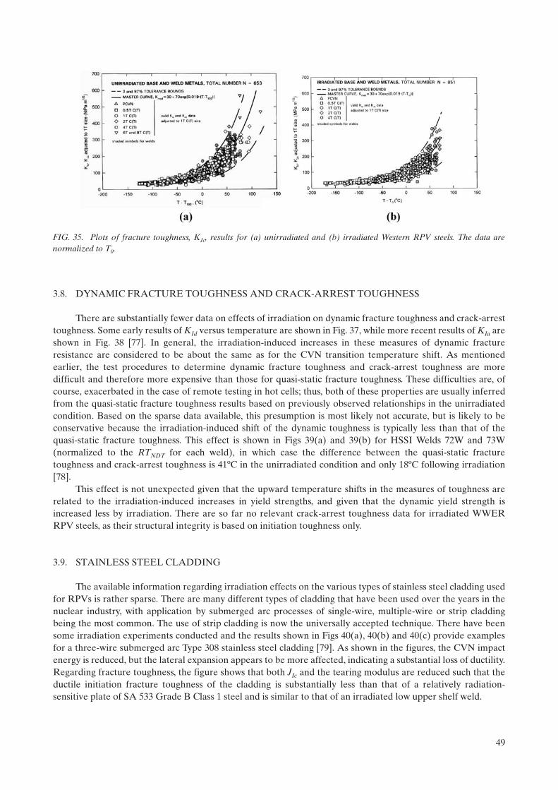
3.8. DYNAMIC FRACTURE TOUGHNESS AND CRACK-ARREST TOUGHNESS
There are substantially fewer data on effects of irradiation on dynamic fracture toughness and crack-arrest toughness. Some early results of KId versus temperature are shown in Fig. 37, while more recent results of KIa are shown in Fig. 38 [77]. In general, the irradiation-induced increases in these measures of dynamic fracture resistance are considered to be about the same as for the CVN transition temperature shift. As mentioned earlier, the test procedures to determine dynamic fracture toughness and crack-arrest toughness are more difficult and therefore more expensive than those for quasi-static fracture toughness. These difficulties are, of course, exacerbated in the case of remote testing in hot cells; thus, both of these properties are usually inferred from the quasi-static fracture toughness results based on previously observed relationships in the unirradiated condition. Based on the sparse data available, this presumption is most likely not accurate, but is likely to be conservative because the irradiation-induced shift of the dynamic toughness is typically less than that of the quasi-static fracture toughness. This effect is shown in Figs 39(a) and 39(b) for HSSI Welds 72W and 73W (normalized to the RTNDT for each weld), in which case the difference between the quasi-static fracture toughness and crack-arrest toughness is 41ºC in the unirradiated condition and only 18ºC following irradiation [78].
This effect is not unexpected given that the upward temperature shifts in the measures of toughness are related to the irradiation-induced increases in yield strengths, and given that the dynamic yield strength is increased less by irradiation. There are so far no relevant crack-arrest toughness data for irradiated WWER RPV steels, as their structural integrity is based on initiation toughness only.
3.9. STAINLESS STEEL CLADDING
The available information regarding irradiation effects on the various types of stainless steel cladding used for RPVs is rather sparse. There are many different types of cladding that have been used over the years in the nuclear industry, with application by submerged arc processes of single-wire, multiple-wire or strip cladding being the most common. The use of strip cladding is now the universally accepted technique. There have been some irradiation experiments conducted and the results shown in Figs 40(a), 40(b) and 40(c) provide examples for a three-wire submerged arc Type 308 stainless steel cladding [79]. As shown in the figures, the CVN impact energy is reduced, but the lateral expansion appears to be more affected, indicating a substantial loss of ductility. Regarding fracture toughness, the figure shows that both JIc and the tearing modulus are reduced such that the ductile initiation fracture toughness of the cladding is substantially less than that of a relatively radiation-sensitive plate of SA 533 Grade B Class 1 steel and is similar to that of an irradiated low upper shelf weld.
FIG. 35. Plots of fracture toughness, KJc, results for (a) unirradiated and (b) irradiated Western RPV steels. The data are normalized to T0.
49

3.10. CORRELATIONS AND NORMALIZATION SCHEMES
Because the fracture toughness is the property required for structural integrity evaluations, and because almost all of the available surveillance data are obtained from CVN impact and tensile tests, correlations between fracture toughness and the other properties, especially CVN toughness, are required. Traditionally, the
FIG. 36. Plots of fracture toughness, KJc, results for (a) unirradiated and (b) irradiated WWER-440 RPV steels. The data are normalized to T0.
50

FIG. 37. Plot from the 1970s showing the effects of irradiation on dynamic fracture toughness, KId, versus temperature.
FIG. 38. Plots showing effects of irradiation on crack-arrest toughness, KIa, versus temperature for HSSI Welds 72 and 73W, the same two Western type weld metals as in Figs 25, 28 and 34(a).
51

irradiation-induced shift from CVN impact tests has been used to shift the fracture toughness curve, based on the assumption of a 1:1 correlation between the transition temperature shifts of CVN energy and fracture toughness. Based on the sparse data available in the past, this was a reasonable assumption. The advent of elastic–plastic fracture mechanics provides for the use of relatively small specimens, while the development of E 1921 allows for consistency in measurement of KJc, adjustment for specimen size effects, and characterization of the results with a fixed curve shape and tolerance bounds. These factors have allowed for the development of a database of CVN data and fracture toughness data for cases in which both the CVN, tensile and fracture toughness specimens of the same material were irradiated under the same conditions to about the same fluence. Reference [42] reported analyses of such a database and showed results of various correlations between the different test results. Figures 41(a) and 41(b) from that study show comparisons for Western RPV base metals and welds, respectively.
As shown, T41J and T0 are essentially 1:1 for weld metals, but T0 is 1.16 × T41J for base metals. These correlations are based on 42 and 47 individual sets of data, respectively, and, as reported in Ref. [42], the raw CVN data and the raw KJc data were obtained and analysed by the authors to ensure consistency. It is important to note that the confidence bounds (2) on these correlations are 26ºC and 36ºC for the welds and base metals, respectively. As discussed by the authors, correlative evaluations using other CVN energy indices did not significantly alter the observations. Figure 42 [42] shows a comparison of the CVN 41-J transition temperature and the fracture toughness reference temperature To for the same materials as in Fig. 41, and shows the relationship:
To = T41J 24ºC, ( = 20ºC) (8)
Another correlation in Ref. [42] between CVN transition temperature shifts and yield strength increases shows the relationship:
To = 0.70 × YS (9)
where To is in ºC and YS is in MPa.The coefficient of 0.70 is the same as the value of 0.70 published in Ref. [80] for T41J and YS. Moreover,
Ref. [81] published similar results specifically for ‘low upper shelf’ welds with coefficients ranging from 0.4 to 0.9 for seven different welds and an average value of 0.65, very close to the 0.70 value shown in Eq. (9).
FIG. 39. Comparison of mean fracture toughness and crack-arrest toughness versus normalized temperature for HSSI welds 72 and 73W in (a) unirradiated and (b) irradiated conditions.
52
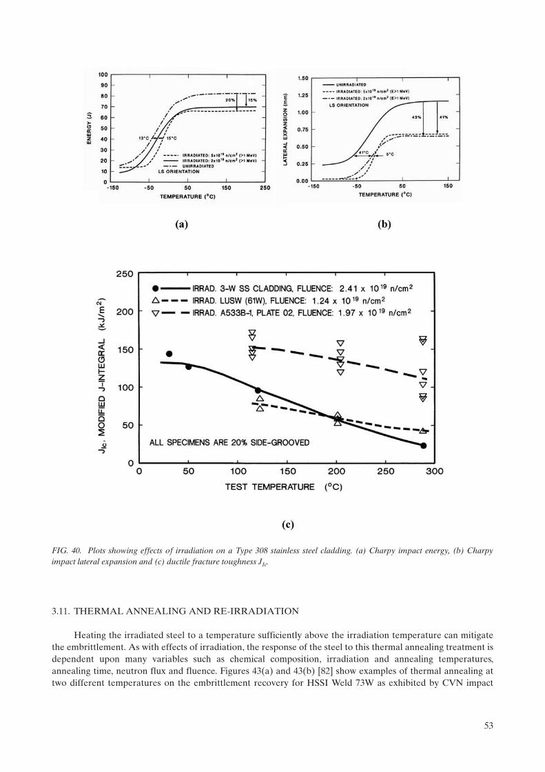
3.11. THERMAL ANNEALING AND RE-IRRADIATION
Heating the irradiated steel to a temperature sufficiently above the irradiation temperature can mitigate the embrittlement. As with effects of irradiation, the response of the steel to this thermal annealing treatment is dependent upon many variables such as chemical composition, irradiation and annealing temperatures, annealing time, neutron flux and fluence. Figures 43(a) and 43(b) [82] show examples of thermal annealing at two different temperatures on the embrittlement recovery for HSSI Weld 73W as exhibited by CVN impact
FIG. 40. Plots showing effects of irradiation on a Type 308 stainless steel cladding. (a) Charpy impact energy, (b) Charpy impact lateral expansion and (c) ductile fracture toughness JIc.
53

energy, while Fig. 44 shows a similar example for fracture toughness [58]. Figures 45(a) and 45(b) show examples of thermal annealing effects on WWER-440 steels [83].
For a given irradiated material, increasing both annealing temperature and time tend to increase the recovery, with temperature having a much stronger effect, and with limits of effectiveness for both. Moreover, especially in the case of steels for the WWER-440 RPV, there are reported instances of irradiated-induced and thermal annealing-induced grain– boundary segregation of phosphorus with resultant intergranular fracture [84]. Although there is experimental evidence of the potential susceptibility of Western steels to temper embrit-tlement [85], these effects have not been observed in Western irradiated RPV steels.
FIG. 41. Comparisons of irradiation-induced shifts of fracture toughness and CVN energy for Western-type RPV (a) weld metals and (b) base metals. As shown, the T41J and T0 are essentially 1:1 for weld metals, but T0 is 1.16 × T41J for base metals.
FIG. 42. Comparison of CVN 41 J transition temperature and the fracture toughness reference temperature T0 for the same Western-type RPV materials as in Fig. 41.
54

These effects are different from microstructural observations such as the so-called ghost lines in some forgings that have been observed to experience intergranular fracture due to phosphorus segregation during manufacture [86]. As with effects of irradiation, the various data from thermal annealing and re-irradiation experiments have been used to develop predictive correlations for recovery and re-irradiation, e.g. [87, 88]. Equations are provided in Ref. [88] for both upper shelf Charpy energy and transition temperature; with annealing temperature and time, and irradiation temperature, fluence and flux included as parameters. One difference in this regard, however, is that all the irradiation correlations are based on reactor surveillance data while most thermal annealing correlations are based on test reactor experiments. Experiments with WWER-440 RPVs have been conducted, however, to include the testing of small specimens removed from the inside surface
FIG. 43. Effects of thermal annealing HSSI Weld 73W for 168 h at (a) 343ºC and (b) 454ºC, on the Charpy impact energy versus temperature.
FIG. 44. Effects of thermal annealing for 168 h at 343ºC and 454ºC on recovery of the Charpy 41J shift and KJc shift of HSSI Weld 73W.
55

of the RPV [89]. Moreover, many annealing operations have been conducted on commercial WWER-440 RPVs and these are discussed in Section 5. Additional discussions of thermal annealing and re-irradiation are presented in Section 5.
4. MECHANISMS GOVERNING THE IRRADIATION-INDUCED EMBRITTLEMENT OF LWR PRESSURE
VESSEL STEELS
In parallel to the investigations of irradiation effects on mechanical properties through research reactor experiments and surveillance programmes, a large effort has been made in many countries to characterize the irradiation-induced damage in RPV steels as well as to understand and model the mechanisms governing this damage. The obtained results were used to successfully support forecasts of steel behaviour in service on a physical basis [90]; they are now used to build numerical tools aimed at simulating irradiation effects.
This section provides a summary of the current knowledge on irradiation-induced damage in Western-type RPV steels (nature of defects, involved mechanisms). In this field, ideas have evolved significantly over the years and many interpretations, mechanisms and models have been put forward to explain experimental data. To show this evolution, the main elements which have marked the way to current understanding are also given.
4.1. MATERIALS AND IRRADIATION CONDITIONS
4.1.1. Description of materials
As discussed in Sections 2 and 3, pressure vessels of current Western-type LWRs were built with welded plates or shells made of high toughness quenched and tempered low-alloyed ferritic steels. During vessel fabri-cation, base metals and welds underwent several stress-relief heat treatments (T 550–610°C), which fashioned their microstructure (carbides, chemical content of solid solution).
FIG. 45. Effects of thermal annealing on WWER-440 steel showing (a) effects of annealing temperature and (b) effects of phos-phorus content.
56

4.1.1.1. Base metals
Most of the base metals are low-alloyed NiMnMo ferritic steels, typically A533B Class 1 and its forging equivalent A508 Class 3 (corresponding to 16MND5 French standard) or A508 Class 2. Some chemical composition specifications are given in Table 4.
A533B and A508-type steels have a tempered bainitic structure in which prior austenitic grains are about 30 µm in size. Transmission electron microscopy (TEM) observations reveal (Fig. 46) that the bainitic grains contain a fairly high density of dislocations, mostly organized in sub-boundaries as well as of small (Fe, Mn)3C- and (Fe, Mo)2C-type carbides ( 40 to 500 nm). The typical width of the bainitic laths is about 1–2 µm.
4.1.1.2. Welded joints
It is noteworthy that the carbon content of weld metal is lower than that of base metal. In general, welded joints have a bainitic–martensitic structure with a very fine carbide distribution.
4.1.2. In-service conditions
Most of the Western-type RPVs operate at a temperature ranging from about 270 to 330°C. They are subject to neutron irradiation, with the peak located at the core mid-plane (beltline region).
The fission process occurring in LWR nuclear fuel produces neutrons of widely differing energy levels. A typical neutron spectrum on the inner surface of a PWR vessel is presented in Fig. 47 and shows that almost all the neutrons have an energy lower than 3 MeV. The total number of neutrons received per time unit (the so-called neutron flux) at the peak location is typically around 1010 to 1011 n cm–2 s–1 for PWRs.
4.1.2.1. Neutron irradiation characterization
Several quantities have been proposed to describe neutron irradiations. Currently used quantities are mostly fluence and the number of displacements per atom.
Fluence: The fluence is the number of neutrons received per surface unit of the irradiated material. Usually, only neutrons of energy higher than a threshold value are considered, supposing that the others have a negligible effect in the irradiated material. For LWR pressure vessels, threshold values of 1, 0.5, 0.68 or 0.1 MeV were initially proposed from theoretical deductions, depending on the country. Later on, some experimental irradiation programmes were carried out to point out the best value. In particular, Serpan showed that a
FIG. 46. Light optical micrographs — typical structure of a A508B Class 3 steel.
57

threshold of 1 MeV is acceptable for fission spectra with a ratio of thermal to fast (E > 1 MeV) neutron fluxes smaller than about ten. A more recent study, carried out with extreme care in the control of the experimental conditions, concluded that for PWRs a threshold of 1 MeV is more relevant than 0.1 MeV. Currently, threshold values of 1 and 0.5 MeV are used in Western and Eastern countries, respectively.
Displacements per atom: Fluence only counts the neutrons and does not allow for their effects in displacing atoms in the material. Thus, it gives the same weight to neutrons with very different energies (e.g. 1 and 3 MeV neutrons are not distinguished) and is therefore independent of the shape of the neutron spectrum. To characterize irradiations with a better description of the irradiation-induced damage, the number of displace-ments per atom (dpa) was developed in the mid-1950s. This number is also called dose, or dose rate when expressed by time unit (dpa/s).
The number of dpa is equal to the total number of Frenkel pairs (one vacancy + one self-interstitial atom) created in a given volume by the neutrons, divided by the number of atoms in this volume. Several models have been set forth to calculate the number of produced Frenkel pairs; the most commonly used is that proposed by Norgett, Robinson and Torrens leading to the so-called NRT-dpa [104].
The number of dpa can be considered as the average number of times each atom in the material has been ejected from its lattice site during the irradiation. It increases with the amount of energy deposited in the material by the neutrons and, thus, depends on the shape of the neutron spectrum.
4.1.2.2. In-service fluence and dpa
For most Western-type LWR pressure vessels, the flux of neutrons with energy higher than 1 MeV has a value of some 1010 n cm–2 s–1 at the irradiation peak location, leading to a fluence of some 1019 n/cm2 and a dose of some hundredths of dpa for 32 years full power operation (for typically French PWRs, flux 6 1010 n cm–2 s–1, fluence 6 1019 n/cm2 and dose 0.1 dpa).
Such values are rather low compared to what is experienced by other reactor components (e.g. typical flux on internal structures is about 6 1013 n cm–2 s–1). However, they are high enough for the irradiation to induce changes in the properties of ferritic steels, as described in Section 3.
4.2. IRRADIATION EFFECTS IN RPV STEELS
For discussion of effects of irradiation on mechanical properties, see Section 3.
FIG. 47. Typical neutron spectrum on the inner surface of a PWR vessel.
58

4.2.1. Chemical composition
Effects of impurities on the sensitivity of RPV steels to irradiation embrittlement were experimentally shown for the first time in 1967 on a laboratory A302-B heat, confirmed on commercial A533-B heats in 1970 and then extensively studied until the mid-1990s. An analysis of the results produced has to be based on the concentrations of impurities in solid solution. These concentrations may indeed largely differ from nominal ones since such elements can intensively precipitate or segregate during steel making or heat treatments prior to irradiation. As an example, in welds with nominal copper content of about 0.2 at%, Miller measured bulk copper levels of about 0.14 at% in the as-received conditions (stress-relief heat treatment at about 600°C); similar results are also available for nitrogen. The solubility limit of each element depends on the whole chemistry of the steel; as a first approximation, Table 12 gives some examples in pure iron at 575°C and 290°C.
4.2.1.1. Copper
As discussed in Section 3, copper is one of the elements that has the most deleterious effects on the irradiation-induced embrittlement of RPV steels. This effect appears from a copper content of about 0.04% and becomes very strong above 0.1%. From the 1970s, the total copper content in RPV steels and their welds has been limited to a maximum value of 0.1%, and to even lower values in most Western countries (e.g. 0.07% in France).
Copper contents in recent RPV steels are lower than the solubility limit of this element at the temperature of stress-relief heat treatment (0.17% in pure iron) [91]. Thus, it can be considered that in such steels a large proportion of the copper atoms is in solid solution when the vessel is commissioned (a part may have precipi-tated during the cooling following the stress-relief treatment). As the copper solubility limit at the irradiation temperature is very low ( 0.007% in pure iron), copper atoms have a propensity to form precipitates or clusters in RPV steels in operation.
4.2.1.2. Phosphorus
Phosphorus has a well known deleterious effect on thermal ageing of ferritic steels due to its propensity to intergranular segregation. The phenomenon is known as thermal equilibrium segregation and is particularly significant in the temperature range 350 to 600°C. To limit or avoid this phenomenon, chemical compositions of ferritic steels have been optimized for a long time (specification for P content, addition of Mo, etc.). In parallel, several models have been developed to forecast the phosphorus content in grain boundaries.
In spite of this optimization, a deleterious effect of phosphorus on irradiation-induced embrittlement of RPV steels was revealed from the early 1970s. Experimental programmes showed that for concentrations higher than about 0.015%, the shift in the Charpy transition curve was strongly reinforced as the phosphorus content increased. No significant effect on hardness or yield stress was reported, implying an effect of temper embrit-tlement as discussed in Section 3. However, it was suggested that the phosphorus effect could decrease with increasing copper content (see Fig. 30).
Experimental results are insufficient to allow the dependence of P segregation on parameters such as dose rate or irradiation temperature to be determined. Therefore, significant efforts on modelling are underway to provide guidance on conditions enhancing such segregation.
Since the beginning of the 1970s, the phosphorus concentration in RPV steels and their welds has been limited to a maximum value of 0.015% and, later, even lower values, in most Western countries (e.g. 0.008% in
TABLE 12. SOLUBILITY LIMITS OF SOME CHEMICAL ELEMENTS IN IRON
Cu P N Mn Ni
At 575°C (wt%) 0.17 0.27 0.12 2.8 5.4
At 290°C (wt%) 0.007* 0.05* 0.04* 3 4.2
* Ref. [91].
59

France). Such contents are much lower than the solubility limits of this element at the temperatures of stress-relief heat treatment (>0.27% in pure iron), and irradiation. Thus, it can be considered that in RPV steels a large fraction of phosphorus atoms is in solid solution when the vessel is commissioned. Although these atoms have a relatively low tendency to precipitate or cluster in operation, there is increasing evidence that phosphorus contributes to irradiation embrittlement through the mechanism of matrix damage and also by participation in copper-rich precipitates.
4.2.1.3. Nitrogen
Several studies have shown that nitrogen has a minor influence on the irradiation effect sensitivity of RPV steels at temperatures above 250°C. At lower temperature, it may have a major influence.
The free nitrogen content is negligible in aluminium grain size controlled steels, and seems to be around some tens of ppm (20–30 ppm) in Si-killed steels, which is much lower than its solubility limit under operation conditions (400 ppm). It can be considered that nitrogen has a low propensity to precipitate or cluster in service conditions.
4.2.1.4. Tin and arsenic
It has been found that tin weakly contributes to irradiation embrittlement of RPV steels. The same result was obtained for arsenic in the range of contents extending from 42 to 480 ppm.
4.2.1.5. Nickel
Nickel effects have been extensively studied from the beginning of the 1980s. This element has a strong, and so far not fully explained, deleterious impact on irradiation-induced embrittlement of RPV steels. This impact may become very high for nickel contents higher than about 1 or 1.2% and increases with the copper content in a synergetic way. Predictive formulas used in different countries are discussed in Sections 5 and 6, but one example of the importance of Ni is that the US Regulatory Guide 1.99, Revision 2 [90] includes copper and nickel as the two chemical elements in the embrittlement predictive formula.
Nickel contents in RPV steels were expected to be lower than the solubility limits of this element at temperatures of stress-relief heat treatment and irradiation (respectively about 5.4 and 4.2% in pure iron). However, experimental and thermodynamic studies have shown that, in operation, nickel can integrate with copper-rich precipitates in RPV steels. Additionally, as postulated by Odette [92], the thermodynamics approach reveals that nickel could also participate in nickel manganese-rich phases containing a small amount of copper (termed late blooming phases). These phases are assumed to be promoted by high nickel and manganese contents, high fluences, and by low copper and temperature. Their precipitation kinetics would be controlled by the nucleation rate. Recently, experimental studies have verified the existence of MnNi late blooming phases, even in nominally Cu-free alloys [93]. This issue is receiving increased attention within the research community.
4.2.1.6. Manganese
Manganese has not yet been the subject of many dedicated experimental studies. Consequently, its impact on irradiation-induced embrittlement is not so well known.
Manganese contents in RPV steels were expected to be lower than the solubility limits of this element at temperatures of stress-relief heat treatment and irradiation (about 2.8 and 3%, respectively, in pure iron). However, as mentioned above, thermodynamics and experimental studies have shown that, in operation, manganese can integrate with copper-rich precipitates. It also participates in the previously mentioned Ni/Mn-rich late blooming phases. In a recently completed IAEA CRP, it was noted that “For a given high level of nickel in the material and all other factors being equal, high manganese content leads to much greater irradiation-induced embrittlement than low manganese content for both WWER-1000 and PWR materials” [94].
60

4.2.2. Metallurgical structure
Some experimental studies were performed to assess the influence of the microstructure on the irradiation embrittlement sensitivity of RPV steels. In particular, Vacek carried out a comprehensive study on this topic. By appropriate heat treatments, he prepared products with different structures from the same heat, and irradiated them at 285 10°C with a fluence of about 7.3 1019 n/cm2 (E > 1 MeV). For each structure, the irradiation effects were characterized by Charpy and tensile tests. The main results are summarized in Table 13. From those results, it appears that the irradiation-induced embrittlement is almost independent of the microstructure, even though the unirradiated properties are quite different. The hardening results, however, do indicate an effect of microstructure.
Statistical analysis of experimental results has led to the separation of weld and base metal behaviours and even the ones of welds, plates and forgings [95]. For given irradiation conditions and chemical composition, regressions forecast that the embrittlement of welds and plates are similar and somewhat higher than that of forgings. Reference [95] notes that such differences are not surprising, given microstructural and chemical composition variations. It is also important to note that post-weld heat treatment conditions are not directly accounted for in these studies.
4.2.3. Irradiation parameters
4.2.3.1. Temperature
As discussed in Section 3.6, temperature has a strong influence on irradiation embrittlement of RPV steels, the level of embrittlement being reduced by increasing temperature. Some results have shown that this influence depends on the steel chemistry and irradiation conditions.
4.2.3.2. Spectrum
As already mentioned, several experiments [96] were performed to assess the neutron spectrum effect on RPV steel embrittlement. A recent study (French programme ESTEREL) was carried out with extreme care to compare the effects of two neutron spectra on the embrittlement of medium (Cu = 0.09%, Ni = 0.68%, P = 0.0198%) and low (Cu = 0.05%, Ni = 0.76%, P = 0.0081%) irradiation-sensitivity steels. The spectra were repre-sentative of those on the inner surface of the vessel and the surveillance capsules of PWRs. No significant spectrum effect was revealed for those conditions [97].
Irradiations carried out in reactors with spectra very different from those of LWRs showed that thermal neutrons may have a significant effect on embrittlement when the ratio of thermal to fast neutron fluxes is higher than about ten:
TABLE 13. IRRADIATION RESPONSES OF DIFFERENT STEEL STRUCTURES PREPARED FROM THE SAME HEAT, TIRR = 285°C ± 10°C, FLUENCE 7.3 1019 n/ cm2, (CU = 0.15%, P = 0.013%, NI = 3.28%, MN = 0.39%)
Tempered martensite
Temperedbainite
Tempered ferrite + perlite + bainite
+ martensite
Tempered martensite + bainite
Tensiletests
Rp0.2* (MPa) 761* 653* 668* 643*
Rp0.2 (MPa) 221 246 276 309
Charpytests
T41* (°C) –143* –73* –118* –74*
T41 (°C) 144 146 146 137
E* (J) 153* 155* 155* 145*
E (J) –39 –49 –52 –52
* Value determined on non-irradiated material.
61
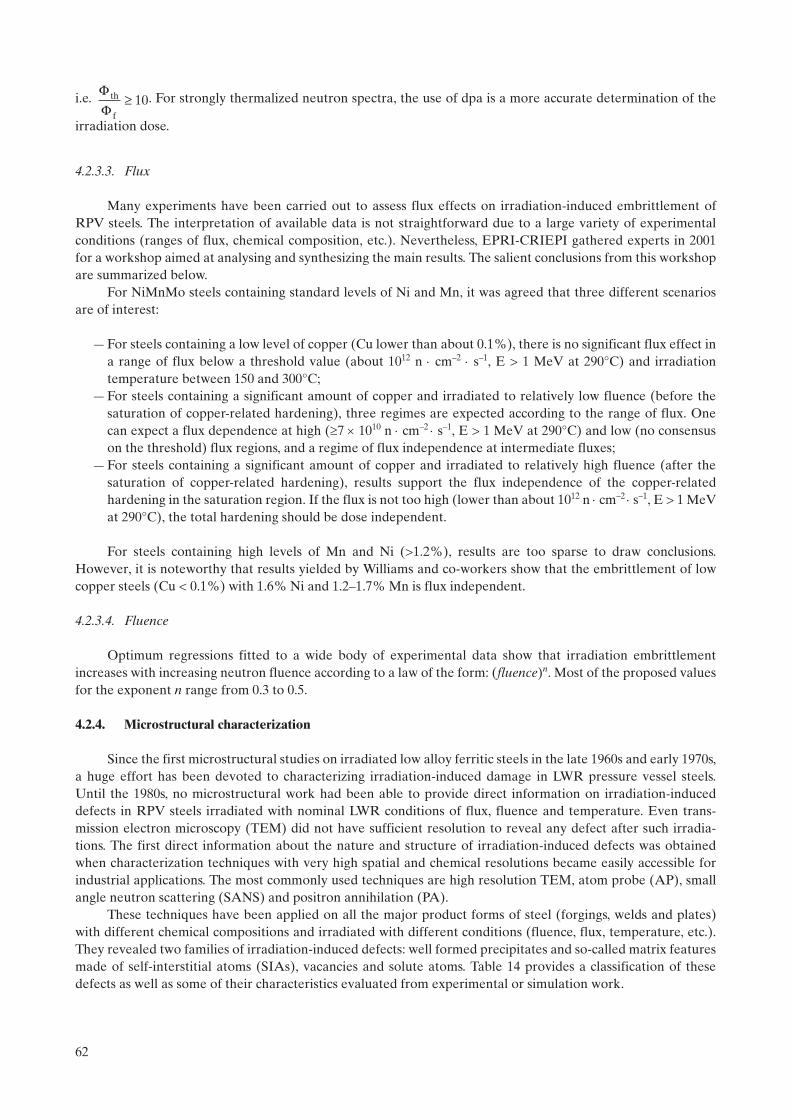
i.e. . For strongly thermalized neutron spectra, the use of dpa is a more accurate determination of the
irradiation dose.
4.2.3.3. Flux
Many experiments have been carried out to assess flux effects on irradiation-induced embrittlement of RPV steels. The interpretation of available data is not straightforward due to a large variety of experimental conditions (ranges of flux, chemical composition, etc.). Nevertheless, EPRI-CRIEPI gathered experts in 2001 for a workshop aimed at analysing and synthesizing the main results. The salient conclusions from this workshop are summarized below.
For NiMnMo steels containing standard levels of Ni and Mn, it was agreed that three different scenarios are of interest:
— For steels containing a low level of copper (Cu lower than about 0.1%), there is no significant flux effect in a range of flux below a threshold value (about 1012 n cm–2 s–1, E > 1 MeV at 290°C) and irradiation temperature between 150 and 300°C;
— For steels containing a significant amount of copper and irradiated to relatively low fluence (before the saturation of copper-related hardening), three regimes are expected according to the range of flux. One can expect a flux dependence at high (7 1010 n cm–2 s–1, E > 1 MeV at 290°C) and low (no consensus on the threshold) flux regions, and a regime of flux independence at intermediate fluxes;
— For steels containing a significant amount of copper and irradiated to relatively high fluence (after the saturation of copper-related hardening), results support the flux independence of the copper-related hardening in the saturation region. If the flux is not too high (lower than about 1012 n cm–2 s–1, E > 1 MeV at 290°C), the total hardening should be dose independent.
For steels containing high levels of Mn and Ni (>1.2%), results are too sparse to draw conclusions. However, it is noteworthy that results yielded by Williams and co-workers show that the embrittlement of low copper steels (Cu < 0.1%) with 1.6% Ni and 1.2–1.7% Mn is flux independent.
4.2.3.4. Fluence
Optimum regressions fitted to a wide body of experimental data show that irradiation embrittlement increases with increasing neutron fluence according to a law of the form: (fluence)n. Most of the proposed values for the exponent n range from 0.3 to 0.5.
4.2.4. Microstructural characterization
Since the first microstructural studies on irradiated low alloy ferritic steels in the late 1960s and early 1970s, a huge effort has been devoted to characterizing irradiation-induced damage in LWR pressure vessel steels. Until the 1980s, no microstructural work had been able to provide direct information on irradiation-induced defects in RPV steels irradiated with nominal LWR conditions of flux, fluence and temperature. Even trans-mission electron microscopy (TEM) did not have sufficient resolution to reveal any defect after such irradia-tions. The first direct information about the nature and structure of irradiation-induced defects was obtained when characterization techniques with very high spatial and chemical resolutions became easily accessible for industrial applications. The most commonly used techniques are high resolution TEM, atom probe (AP), small angle neutron scattering (SANS) and positron annihilation (PA).
These techniques have been applied on all the major product forms of steel (forgings, welds and plates) with different chemical compositions and irradiated with different conditions (fluence, flux, temperature, etc.). They revealed two families of irradiation-induced defects: well formed precipitates and so-called matrix features made of self-interstitial atoms (SIAs), vacancies and solute atoms. Table 14 provides a classification of these defects as well as some of their characteristics evaluated from experimental or simulation work.
FF
th
f
≥ 10
62

The existence of some features containing solute atoms (vacancy-solute clusters, atmospheres, etc.) is still under discussion and some research groups are engaged in scientific controversies about them. In fact, some of these defects could be of the same type but appear to have different shapes in microstructural or simulation studies due to differences of irradiation conditions (flux, etc.) or steel chemical compositions.
Thermal annealing experiments carried out on irradiated RPV steels at a temperature close to the irradiation temperature also gave some insight into irradiation-induced defects. Indeed, they led to an evolution of hardness (partial recovery or small increase [91]) which suggests that defects are unstable and exist under irradiation due to a non-equilibrium state (i.e. they have a lifetime) imposed by the irradiation.
The following paragraphs briefly summarize some salient results of microstructural studies; for additional details, a substantial number of references is provided.
4.2.4.1. Atom probe
Atom probe (AP) has its origin in the field-ion microscope (FIM) invented in 1951. It was first presented in 1968 under the name of atom probe field ion microscopy (APFIM) and has undergone several developments, including the more recent possibility to determine the nature and the 3D position of atoms within a small specimen volume, designated atom probe tomography (APT) [98]. The technique suffers from some limitations, in particular from the fact that the characterized volume is very small (about 103 nm3) which leads to results with a low statistical character (quite new developments have been made, however, that can increase the charac-terized volume by about a factor of four). Furthermore, only about 60% of the atoms of the studied volume are analysed, which can lead to a misinterpretation of the results. Additionally, AP and APT do not reveal small vacancy clusters and dislocation loops in complex structures such as RPV steels.
The first use of AP on irradiated pressure vessel steels was experienced in 1981 by Miller and Brenner on the A302-B steel (the first use on a model alloy related to RPV embrittlement was carried out in 1973 by Goodman et al. on a binary Fe–1.4%Cu). Since then, many types of irradiated base metals and welds have been characterized with this technique, and Fig. 48 and Table 15 summarize some results.
For steels with a copper content greater than 0.05%, AP reveals that Cu, Mn, Ni and Si atoms are not randomly distributed after irradiation. It is also observed that there are some spatial correlations between the distributions of pairs of atoms: for example, Mn and Cu, Mn and Ni, Si and Ni, etc. [99]. As the fluence increases, the correlations increase and, finally, clusters of Mn, Cu, Ni and Si are observed. The threshold dose from which these defects are detected seems to decrease as the steel copper content increases (see Fig. 48).
Examples of AP results concerning size, chemical composition and number density of Cu, Mn, Ni and Si clusters are given in Table 15. Whatever the fluence and steel chemical composition, these defects have a radius smaller than 2 nm and mainly contain iron atoms (Fig. 49). On the contrary, their number density increases with copper and nickel content as well as with fluence: on a commercial steel (Cu = 0.09%), Pareige measured a steady increase of the cluster number density from 3 to 11 1017 cm–3 as the fluence goes from 2.5 to 16 1019 n/cm2 [99].
As the copper content in the steel increases, the clusters are better defined and their Cu, Mn and Ni concentrations increase. However, they always contain a large amount of iron, even for a steel copper content of 0.55%. AP composition profiles across clusters reveal that the spatial extent of the manganese, nickel and silicon
TABLE 14. IRRADIATION-INDUCED DEFECTS IN RPV STEELS
Type Radius (nm) / Number density Composition
Copper-rich precipitates 0.5–1.5 nm / some 1024 m–3 Cu (>50%) — Mn–Ni–Si
Manganese nickel-rich precipitates Similar to copper rich precipitates Mn–Ni–Si (>50%) — Cu
Dilute solute atmospheres <2 nm / <1024 m–3 Fe–Cu–Mn–Ni–Si
Vacancy-solute clusters <0.5–1.5 nm / <1024 m–3 Vacancies — Cu–Mn–Ni–Si
Nanovoids <0.5 nm / <1024 m–3 Vacancies — Cu–Mn–Ni–Si
SIA clusters <0.3 nm / some 1024 m–3 —
SIA dislocation loops <0.8 nm / some 1024 m–3 —
63

TABLE 15. AVERAGE SIZE AND CHEMICAL COMPOSITION OF SOLUTE ATOM CLUSTERS MEASURED BY AP
Ref. SteelFluence
(1019 n/cm2)Nd
(1017 cm–3)Radius(nm)
Cu(at%)
Mn(at%)
Ni(at%)
Si(at%)
[91] Base metal Bulk chemical composition 0.06 1.26 0.70 0.38
4.6a 0.6 2 0.7 3.2 6.2 3.6
[91] Base Metal Bulk chemical composition 0.06 1.34 0.7 0.54
5.2a 1 2 0.4 2.3 5.7 4.9
[99] Base metal Bulk chemical composition 0.08 1.32 0.68 0.80
2.5a 3.3 1.5 0.9 7.4 4.7 2.7
6.6a 5.7 1.5 1.5 3.6 4.2 3.8
12a 9 2 0.9 3.8 3.6 4.8
[100] Weld Bulk chemical composition 0.27 1.58 0.57 0.89
2.0b 6.4 1.3 29.2 6.1 4.6 2.3
[101] Weld Bulk chemical composition 0.3 ? 0.58 0.61c 10 0.7–1 27 3.5 8 4.5
Weld Bulk chemical composition 0.22 c 1.00 0.21c c <1 15 10 5 2
a Irradiated at about 290°C.b Irradiation temperature not given.c Information not given.
FIG. 48. Steel copper contents and doses for which Mn, Ni, Cu and Si clusters have been detected by AP in irradiated RPV steels [91, 99, 101].
64

enrichments are generally slightly larger than those of copper (Fig. 49(b)). For copper-rich clusters, these three elements seem to concentrate at the interface with the matrix [100].
It is important to note that among the solute atoms in the clusters, copper invariably has the highest enrichment factor over the matrix level. Consequently, a significant depletion of the copper content occurs in the matrix; this content tends to a lower limit of about 0.03–0.04%, which is still much higher than the solubility of copper at 290°C (about 0.007%) [91]. For steels with a copper content of about 0.10–0.15%, this limit is reached at a fluence of about 2 1019 n/cm2. No significant depletion of the matrix has been measured for nickel, manganese and silicon.
Due to their low concentration in solute atoms, irradiation-induced clusters revealed by AP are often called ‘atmospheres’ or ‘clouds’. Their dilution aspect is clearly shown by 3D AP characterizations on neutron-irradiated binary Fe–Cu alloys (Fig. 49(c)) [99]. The reason why such defects keep a dilute morphology and do not collapse in a real precipitate is an issue still under discussion. One possible explanation could be the presence of a high vacancy concentration within the defects.
FIG. 49. AP analyses of neutron-irradiated alloys [99]. (a) Solute atom cluster obtained in RPV steel. (b) Composition profiles across an irradiation-induced solute atom cluster. (c) Cu cluster observed by AP in a Fe–0.1% Cu alloy.
65

For steels with a copper content lower than 0.05%, no cluster of Cu, Ni, Mn and Si has been reported so far (Fig. 48). However, the non-random distribution of manganese, nickel and silicon atoms is still clearly revealed after irradiation.
4.2.4.2. Small angle neutron scattering
SANS has the ability to reveal and characterize features with a diameter larger than about 1 nm. It allows us to analyse a volume of material on the order of some hundreds of cubic millimeters and, thus, can provide statistically relevant information on the analysed features, in particular on their sizes and size distributions. Determination of their volume fraction and then their number density from the SANS signal may require assumptions concerning their chemical composition and magnetic properties.
SANS was first applied on irradiated RPV steels in 1984. Since then, many types of irradiated base metals and welds have been characterized with this technique [91]. For such complex materials, the interpretation of the measured signals is not straightforward and requires assumptions based on experience. The most reliable information is about the size distribution of irradiation-induced defects. The determination of the number densities is more ambiguous since it requires presupposing the nature of the different features (in particular chemical composition, vacancy content, etc.).
Most of the results show that irradiation-induced defects have an average radius ranging between 1 and 1.5 nm. In most cases, they also reveal that the number density of defects increases with fluence. In some cases, it was feasible to carry out SANS and AP analysis on the same irradiated steel [91]. It was, therefore, possible to treat the SANS signal using the chemical composition of the solute atom clusters obtained by AP. With some assumptions on the magnetic properties and vacancy content of the defects, it was possible to conclude that both techniques give about the same number densities of irradiation-induced defects [102]. However, SANS data also provide strong evidence of high densities of nanofeatures in steels where AP does not reveal any clusters. This lack of consistency clearly shows the limits of the studies aimed at characterizing irradiation-induced defects in RPV steels and the necessity to carry out continuing research in this field.
4.2.4.3. Positron annihilation spectroscopy
PAS is a well established technique used to characterize features containing vacancies (vacancy clusters, vacancy-solute clusters). The method is based on the trapping of positrons at open-volume defects and relies on several methods to analyse the signals; e.g. Doppler broadening and positron life time measurements. It can also reveal ultra fine embedded particles even if they do not contain vacancies.
Some PAS experiments have been carried out on irradiated RPV steels. However, due to the radioactivity and complex structure of such materials as well as to the superposition of several signals, they lead to rather unconvincing results.
Studies with model alloys tend to reveal that neutron irradiation induces the formation of small microvoids (10 vacancies) or vacancy-solute clusters.
4.2.4.4. Transmission electron microscopy
As already mentioned, there is no direct TEM observation of irradiation-induced defects in RPV-steels irradiated in LWR conditions. However, TEM reveals pure copper precipitates in neutron-irradiated high copper ferritic alloys. It also reveals point defect clusters in ferritic alloys (Fe, Fe–Cu, RPV steels) irradiated with conditions different from LWRs; e.g. higher neutron flux or fluence, lower irradiation temperature, electron or ion irradiations. Thanks to these possibilities, many TEM studies have been carried out to get a better under-standing of the nature, structure and conditions of formation of irradiation-induced defects in RPV steels.
4.3. MECHANISMS CONTROLLING THE FORMATION OF IRRADIATION-INDUCED DEFECTS
In materials under neutron irradiation, neutrons hit lattice-atoms, which are called primary knock-on atoms (PKAs). If the transferred energy during such a collision is higher than the displacement threshold energy
66

Ed (e.g. for pure iron, Ed has an effective value of 40 eV [103]), the PKA leaves its site and starts moving through the lattice. The initial kinetic energy of the PKA is called ‘recoil energy’.
During its displacement, a PKA may be slowed down by interactions with electrons and/or collisions with other atoms, which are called secondary knock-on atoms (SKAs). These SKAs can also leave their site and then be slowed down by the same mechanisms; the tertiary knock-on atoms can proceed in the same way and so on. This process results in a series of atomic displacements designated a ‘displacement cascade’.
Once all the PKA energy is dissipated through such interactions, most of the created vacancies and SIAs annihilate each other. At the end of this recombination phase, only some surviving point defects still exist. The whole process is called primary damage and can be characterized by several physical parameters: for example, total number of Frenkel pairs created, number and configuration of surviving defects, etc.
The atomic rearrangements produced by displacement cascades make a weak contribution to the evolution of the properties of irradiated RPV steels. It is the migration of some of the surviving point defects, which is responsible for such evolution. Indeed, by diffusion, these defects form clusters, and interact with solute atoms and impurities, etc. All these phenomena lead to the formation of hardening defects and segregation.
To precisely depict the irradiation-induced evolution of the microstructure of RPV steels, it is required that: (i) the primary damage is first described; (ii) it is explained how this damage impacts the distribution of solute atoms and leads to the nucleation of hardening defects; and (iii) it is shown how the growth of these defects occurs as well as the intergranular segregation of impurities. The next section deals with all of these points.
4.3.1. Primary damage
The primary damage is closely related to the PKA energy. Several codes can be used to determine the PKA spectrum (number of PKAs created per time and volume units versus their kinetic energy) induced by a given neutron spectrum.
4.3.1.1. Historical background
The perspective on primary damage has evolved from the model of Kinchin and Pease (the first model to calculate the number of displaced atoms, (E), produced by a PKA), that of Brinkman (he clearly illustrated vacancies in the central core of the cascade and SIAs on its periphery), that of Seeger (proposed ejection of SIAs far from the cascade area), that of Lindhard (allows for PKA damage energy), and then to Norgett, Robinson, Torrens [104].
Table 16 gives some comparisons between damage energy and recoil energy in iron. No knowledge of the structure is required in the Kinchin and Pease model. Schematic diagrams of both the Brinkman and Seeger models are shown in Fig. 50. Norgett, Robinson and Torrens (NRT) improved the Kinchin and Pease expression by proposing the following one:
TABLE 16. KINETIC AND DAMAGE PKA ENERGIES VERSUS NEUTRON ENERGY
Neutron energy (keV)
Average PKA kinetic energy (recoil) (keV)
Corresponding PKA damage energy (keV)
3.4 0.116 0.1
5.8 0.236 0.2
14 0.605 0.5
36 1.24 1.0
74 2.54 2.0
190 6.6 5.0
400 13.7 10.0
830 28.8 20.0
1800 61.3 40.0
67

(10)
where the factor 0.8 replaced the Kinchin and Pease factor of 2 to account for realistic collisions between atoms (atoms do not fully behave as hard spheres). The NRT expression is used to calculate the so-called NRT dpa.
4.3.1.2. Current vision of primary damage
Displacement cascades cannot be studied experimentally due to their short lifetime (some picoseconds) and small space extension (some nanometers). This is why many efforts have been devoted to simulate them. The first simulations were carried out by Vineyard and co-workers at the Brookhaven National Laboratory in the 1960s and dealt with very low PKA energies. Since the end of the 1970s, the increase of computer power and the development of several simulation techniques have allowed us to obtain a precise picture of high energy cascades. This picture confirms the principles developed by Brinkman and Seeger.
The commonly used simulation techniques are binary collision approximation (codes: MARLOWE, TRIM, INCAS) or molecular dynamics (codes: MOLDY, MDCASK, DYMOKA). Both techniques work at the atomic scale and, therefore, require collision cross-sections or inter-atomic potentials to describe interactions between atoms.
For PKA energies up to 100 keV, the most precise insight on displacement cascades is given by molecular dynamics (MD). An example of simulation is presented in Fig. 51. It shows two main phases:
— A ballistic (or collision) phase lasting a few tenths of a picosecond. During this phase, the energy of the PKA is distributed by multiple collisions among atoms, with the result that they leave their lattice sites. This creates a central disordered core surrounded by a mantle of SIAs. There are also a few SIAs created by replacement collision sequences which represent a minor part of those produced. The zone affected by the phenomenon reaches its maximal extension (peak) at the end of this phase;
— A recombination phase, during which most of the SIAs in the outer mantle return to lattice sites by athermal relaxation, lasts some picoseconds. The non-recombined SIAs and vacancies constitute the so-called ‘surviving defects’.
n ( ).
EE
Edam
d
=0 8
2
FIG. 50. First models of primary damage: (a) Brinkman’s model and (b) Seeger’s model, depicting ejection of SIAs far from the displacement cascade area by (i) channelling along dense atomic planes and (ii) replacement collision sequences.
68

In the framework of studies on RPV steels, a large effort has been made to characterize displacement cascades in pure iron or binary alloys (Fe–Cu, etc.). Results obtained by binary collision or molecular dynamics simulations depend closely on the used collision cross-sections or inter-atomic potentials. However, the ‘irradi-ation effects community’ agrees on the following points for RPV steels:
— Substitutional alloying atoms, such as Mn and Ni, and impurities such as Cu, do not significantly affect the ballistic and recombination phases (during some tens of picoseconds) of displacement cascades, which can therefore be studied in pure iron. However, to reinforce this conclusion, effects of carbon and nitrogen still need to be investigated;
— The size of the zone affected by a displacement cascade increases as the energy of the PKA rises;— When the damage energy is high enough, cascades split into sub-cascades, schematically shown in Fig. 52.
As generally proposed, it can be considered that sub-cascades are formed whenever a large part of atomic
FIG. 51. Displacement cascade as simulated by MD in pure iron at 100 K. Cascade damage energy: 15 keV (recoil energy: 21 keV).
FIG. 52. Splitting of a displacement cascade into sub-cascades as simulated by MD in pure Fe at 100 K. Cascade damage energy: 40 keV (recoil energy: 61 keV).
69
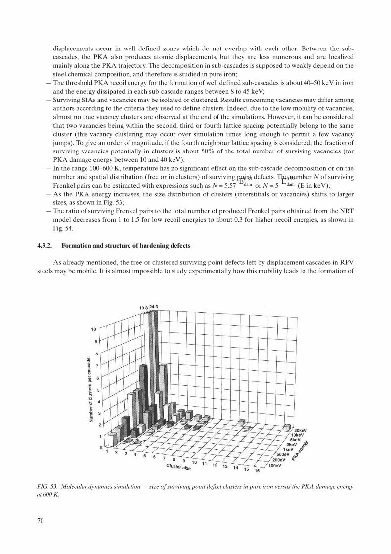
displacements occur in well defined zones which do not overlap with each other. Between the sub-cascades, the PKA also produces atomic displacements, but they are less numerous and are localized mainly along the PKA trajectory. The decomposition in sub-cascades is supposed to weakly depend on the steel chemical composition, and therefore is studied in pure iron;
— The threshold PKA recoil energy for the formation of well defined sub-cascades is about 40–50 keV in iron and the energy dissipated in each sub-cascade ranges between 8 to 45 keV;
— Surviving SIAs and vacancies may be isolated or clustered. Results concerning vacancies may differ among authors according to the criteria they used to define clusters. Indeed, due to the low mobility of vacancies, almost no true vacancy clusters are observed at the end of the simulations. However, it can be considered that two vacancies being within the second, third or fourth lattice spacing potentially belong to the same cluster (this vacancy clustering may occur over simulation times long enough to permit a few vacancy jumps). To give an order of magnitude, if the fourth neighbour lattice spacing is considered, the fraction of surviving vacancies potentially in clusters is about 50% of the total number of surviving vacancies (for PKA damage energy between 10 and 40 keV);
— In the range 100–600 K, temperature has no significant effect on the sub-cascade decomposition or on the number and spatial distribution (free or in clusters) of surviving point defects. The number N of surviving Frenkel pairs can be estimated with expressions such as N = 5.57 or N = 5 (E in keV);
— As the PKA energy increases, the size distribution of clusters (interstitials or vacancies) shifts to larger sizes, as shown in Fig. 53;
— The ratio of surviving Frenkel pairs to the total number of produced Frenkel pairs obtained from the NRT model decreases from 1 to 1.5 for low recoil energies to about 0.3 for higher recoil energies, as shown in Fig. 54.
4.3.2. Formation and structure of hardening defects
As already mentioned, the free or clustered surviving point defects left by displacement cascades in RPV steels may be mobile. It is almost impossible to study experimentally how this mobility leads to the formation of
83.0damE 74.0
damE
FIG. 53. Molecular dynamics simulation — size of surviving point defect clusters in pure iron versus the PKA damage energy at 600 K.
70

hardening defects. However, comparison of experimental results can bring relevant information on the involved mechanisms. Such a comparison is presented in Section 4.3.2.1.
To get around experimental difficulties, a large effort has been underway to study the formation of hardening defects by numerical simulation. The commonly used simulation techniques are Metropolis Monte Carlo (MMC), Atomic Kinetic Monte Carlo (AKMC), Object Kinetic Monte Carlo (OKMC), Event Kinetic Monte Carlo (EKMC) and Rate Theory (RT). Results obtained by these simulation techniques are presented in Section 4.3.2.2.
4.3.2.1. Experimental results
The understanding of the mechanisms controlling the formation of irradiation-induced defects in RPV steels from experimental results is not straightforward due to the large variety of the involved phenomena and participating types of atoms. Separating the various components consists of: (i) working on pure Fe, binary or ternary alloys so as to identify the role played by each type of solute atom or impurity and/or (ii) carrying out electron irradiations (in this case, the primary damage is limited to isolated Frenkel pairs) so as to identify the role played by the isolated point defects, and by comparison with neutron irradiations, to understand the role played by displacement cascades.
Many studies have been carried out on Fe and Fe–Cu alloys irradiated at about 290°C to understand the key role played by copper in irradiation-induced embrittlement of RPV steels. A comparison of results of such studies is given in Table 17 and can be summarized in the following way [99]:
— No hardening of pure iron is observed after electron irradiation (2.5 MeV) with a fluence up to 2 1019 e–/cm2, while neutron irradiation with a fluence of 5.5 1019 n/cm2 induces about 20 HV hardening. This comparison suggests that displacement cascades ease the nucleation of point defect clusters;
— In very low copper steels (Cu < 0.05%) at typical PWR fluences, no clusters of solute atoms are observed after neutron irradiation (Fig. 48), while Cu, Mn, Ni and Si clusters are revealed in irradiated steels containing more than 0.05% copper. This comparison suggests that the presence of Cu is required for the clustering of Mn, Ni and Si; the propensity of these elements to remain in solid solution in low copper
FIG. 54. Energy dependence of the number of surviving point defects relative to the NRT model versus the PKA damage energy.
71

steels is coherent with their high solubility limits in iron. However, as discussed in Section 4.2.1 regarding effects of nickel, there is an increasing tendency for MnNi clustering at higher fluences, even with very low or no Cu content;
— Comparison of results obtained on Fe–Cu binary alloys after neutron and electron irradiations reveals that at least two mechanisms control the nucleation of Cu clusters in iron-based alloys:
• For low Cu content (0.1%), electron irradiation (primary damage limited to a production of isolated Frenkel pairs) does not induce any clustering of Cu atoms, while such clustering is induced by neutron irradiation (primary damage including isolated Frenkel pairs and displacement cascades). This emphasizes the existence of a nucleation mechanism assisted by displacement cascades. The role of displacement cascades in the nucleation of clusters of solute atoms has been confirmed by a recent study carried out with ion irradiations [105];
• For higher Cu content (Cu > 0.1%), AP shows pure Cu precipitates after electron irradiation at about 290°C and Cu clusters (containing about 30 at% of iron) after neutron irradiation at the same temper-ature. This comparison suggests that free Frenkel pairs created by electrons enhance the atomic mobility of copper and promote an accelerated precipitation. The resulting precipitates differ from clusters where nucleation has been eased by displacement cascades. Both types of defects should exist in RPV steels.
4.3.2.2. Simulation results
Numerical simulation has provided key information on the mobility of point defects and point defect clusters as well as on the nucleation, long term behaviour (growth of germs, dissolution, etc.) and structure of the hardening defects in RPV steels. The most relevant simulation techniques for this application cannot be used on complex alloys because, as for experimental studies, most of the simulation work has been carried out on Fe and Fe–Cu alloys.
Mobility of point defects and point defect clusters:MD showed that SIA clusters are much more mobile in Fe than vacancy clusters with the same number of
point defects. As this number increases, the mobility of both types of clusters decreases. MD has also revealed that:
— SIAs and SIA clusters have a 1D mobility along <111> directions. They may switch their movement from one <111> direction to another one by thermal activation or when meeting impurities or other SIA clusters, etc. Therefore, their migration is along a 3D path made of 1D segments (it is referred to as a mixed 1D/3D migration). The capacity of clusters to switch their moving direction decreases with their size;
— Mobile SIA loops can interact with each other to form sessile loops. They may also be trapped by solute atoms;
— Vacancy clusters have 3D migrations and perfect vacancy dislocation loops have a 1D migration. At around 290C, vacancy clusters are much less mobile than vacancy loops.
TABLE 17. COMPARISON OF RESULTS OF ELECTRON AND NEUTRON IRRADIATIONS CARRIED OUT ON FE AND FE–CU ALLOYS AT 290°C [102]
Electron irradiation (2 1019 e–/cm2) Neutron irradiation (5.5 1019 n/cm2)
Irradiation-induced defects Hardening Irradiation-induced defects Hardening
Fe Not characterized HV0.5 = 0 Not characterized HV0.5 = 19
Fe–0.1%Cu No defect revealed by AP HV0.5 = 26 Cu clusters (65 at% Fe) revealed by AP
HV0.5 = 53
Fe–0.7%Cu Pure copper precipitates revealed by AP
HV0.5 = 96 Cu clusters (30 at% Fe) revealed by AP
HV0.5 = 137
72

All these MD results are not in full agreement with experimental results or ab initio calculations. As an example, ab initio calculations showed that the <110> dumbbell is the most stable configuration for single SIAs in iron whereas some MD simulations predict that it is the <111> crowdion. Furthermore, recent ab initio calcu-lations revealed that the single <110> dumbbell may have difficulty to thermally rotate so as to migrate along a <111> direction as forecasted by MD. Nevertheless, MD is an efficient tool to obtain information on the behaviour of point defect clusters. It is why several groups are trying to build better Fe inter-atomic potentials, based on empirical or tight binding models.
Short term evolution of surviving point defects:Domain et al. have simulated the short term behaviour at 300°C of residual point defects left by
displacement cascades in Fe–Cu alloys (0.03% Cu 0.3%), by using successively OKMC and AKMC techniques. Their simulations are illustrated in Fig. 55. Whatever the copper content, it appears that:
FIG. 55. Formation of germs of hardening defects from a displacement cascade in an Fe–0.2%Cu alloy. (a) Cascade peak and (b) surviving defects at the end of the recombination phase (MD simulation). (c) SIAs and SIA clusters have left the simulation box (OKMC simulation). (d) Formation of vacancy-copper germs (AKMC simulation).
73

— Within some microseconds, due to their high mobility, all the SIAs and SIA clusters have left the cascade area; some of them had merged and formed larger clusters. During this short period, the vacancies and vacancy clusters remain almost immobile, and some of them have been recombined with SIAs;
— During the following milliseconds, vacancies and vacancy clusters have a 3D motion in the cascade area. During their movements, most of them merge or collect copper atoms and form vacancy-copper clusters.
The simulation techniques used did not reveal any significant subsequent evolution in the cascade area. The largest formed SIA clusters, vacancy clusters and vacancy-copper clusters seem to be stable (at least in the time scale of the simulation) and can be considered as germs of hardening defects. The formation of these germs results from the high density of surviving point defects in the displacement cascade area. It explains how displacement cascades can promote the formation of hardening defects.
Long term evolution of hardening defects:Long term evolution of hardening defects in RPV steels can be simulated using either OKMC (such as
LAKIMOCA, BIGMAC or ALSOME), EKMC (JERK) or RT codes (MFVISC [106]). OKMC and EKMC provide good descriptions of the local geometry (e.g. grain boundaries) and the spatial distribution of defects. However, for simulation of long physical times, they have to be preferentially used to treat small simulation volumes or small numbers of defects, respectively. RT codes allow long term irradiation to be simulated but do not give any information on the spatial distribution of the induced defects (the material is supposed to be homogeneous).
The three techniques do not give access to the defect morphologies which have to be pre-supposed to properly carry out the simulations (e.g. choice of capture radius). They are still objects of many developments (e.g. introduction of 1D/3D mobility of point defect clusters) to improve the representativeness of the simula-tions. In particular, collaborative work is in progress within the REVE initiative (see Section 4.6.3) to compare or combine them. The first comparison was achieved by modelling electron irradiation of thin foil.
To understand the long term evolution of hardening defects in RPV steels, OKMC and RT codes have been applied on pure iron and Fe–Cu alloys. Both techniques predict a strong influence of flux, irradiation temperature and copper content on the irradiation-induced damage. For irradiation conditions similar to those of LWR pressure vessels (Tirr 300°C, dose 0.1 dpa), the formation of SIA clusters (assumed to be dislocation loops), vacancy clusters, vacancy-copper clusters (supposed to have a 3D structure) and pure copper precipitates has been shown. It was observed that the contribution of point defect clusters to the irradiation-induced damage increases as the neutron flux increases and the irradiation temperature decreases: at 290°C, the irradiation-induced damage is mainly made of point defect clusters for a flux of 1013 n × cm–2 × s–1 and of copper-vacancy clusters for a flux of some 1010 n × cm–2 × s–1.
Structure of the hardening defects: Numerical simulation provides the following results on the structure of hardening defects:
SIA clusters: the structure of SIA clusters is not yet fully understood. In particular, the set of properties that distinguishes SIA clusters and SIA dislocation loops is not yet well clarified. According to Puigvi et al., as well as Kuramoto, between about 160 and 200 SIAs are required for a cluster to behave as a dislocation loop.
SIA clusters are often assumed to nucleate on planes and then to form a faulted loop nucleus. They are presumed to move to their stable configuration through shear reactions, as suggested by Eyre and Bullough:
(11)
or
(12)
110{ }
12
11012
10012
111+ =
12
11012
110 100+ =
74

By MD simulations with different Fe inter-atomic potentials, Wirth, Soneda and Domain found that the stable SIA
loops have b = for Burgers vector. Wirth described these loops as mixtures of dumbbells and crowdions on
planes, while Soneda only saw the crowdions. Marian et al. suggested that loops with a Burgers vector could
result from the interaction of two loops of similar size with a Burgers vector.
On the other hand, Osetsky observed that the more stable loops correspond to sets of or crowdions.
These loops have b = or b = for Burgers vectors and their habit planes are close to or ,
respectively.
Vacancy clusters: Several MD studies with EAM-type inter-atomic potentials have shown that, in bcc iron, small vacancy
clusters are more stable in a 3D configuration than in a 2D one. However, with a long range pair potential, Kapinos et al.
noticed that 3D clusters containing more than about 30 vacancies may exhibit some fragments of vacancy platelets,
indicating the beginning of a loop nucleation. They also showed that clusters containing more than about 100 vacancies may
produce a stable nucleus of vacancy loop (b = ). As growing, such a nucleus is assumed to undergo one of the
Eyre–Bullough shear reactions and get a b = or b = Burgers vector. Kapinos et al. also reported that the
probability of following the reaction in Eqs (11) or (12) depends on the number of vacancies in the neighbourhood of the
nucleus: for clusters containing more than 46 vacancies, the reaction in Eq. (12) occurs spontaneously when the number of
vacancies in the close vicinity of the loop exceeds 20% of the total number of vacancies in the cluster; for isolated clusters,
the shear occurs according to the reaction in Eq. (11). These results provide elements to explain how irradiation conditions
(flux, particles, etc.) may affect the nature of the vacancy loops.
Solute atom clusters: The structure of solute atom clusters has been studied by several groups:
— Domain tried to simulate the growth of such clusters from small vacancy-copper germs in an Fe–0.2%Cu alloy. He combined OKMC and LKMC simulation techniques. The irradiation was reproduced in the simulation by introducing a constant flux of vacancies and SIAs. The simulation leads to the growth of a 3D vacancy-copper cluster (Fig. 56) containing similar numbers of vacancies and copper atoms. Due to the presence of vacancies, copper atoms do not form a single compact precipitate. Their distribution is similar to that of the irradiation-induced atmospheres observed with AP in Fe–0.1%Cu alloys (compare Figs 49 and 56). This result suggests that the dilute aspect of such atmospheres could be due to the fact that they contain vacancies (remember that vacancies cannot be observed by AP);
12
111 111
110{ } 10012
111
111 10012
111 100 111{ } 100{ }
110{ }
110{ } 12
11012
111 100
FIG. 56. (a) 3D vacancy-copper cluster obtained by combining OKMC and LKMC in Fe–0.2%Cu (black spheres: copper atoms, white spheres: vacancies). (b) Precipitate of solute atoms obtained by LKMC simulations.
75

— A kinetic–thermodynamic model (DIFFG) has been proposed by Odette and Wirth to follow the solute atom cluster composition and size. The model determines the phase stability in an Fe–Cu–Mn–Ni system by taking into account the influence of the cluster–matrix interfaces. Cluster evolution is modelled by tracking the flows of solute atoms imposed by the difference of chemical potentials in the matrix and precipitates. The cluster radius and composition are followed as a function of time until the potentials of all the constituents are balanced. Irradiation is introduced in the simulation by increasing the diffusion coeffi-cients as an over-saturation of vacancies would do.
The obtained results are in rather good agreement with experimental SANS or AP results. They show that the number density of clusters as well as their Ni and Mn contents increase as the Ni and Mn contents increase in the alloy. They also show that thermodynamics dictates a limited amount of Mn or Ni in the clusters for steels with low Ni or Mn content. However, when both elements are present in the alloy, they combine synergistically in the clusters due to their strong negative interaction enthalpy. The simulations point out that they tend to be mainly concentrated at the interface.
More recently, the same team provided additional information on the clusters by performing LKMC simulations. For this purpose, pair-type inter-atomic potentials were fitted on thermodynamics data. The simulations predicted solute atom clusters with a rather compact structure and a well defined Cu core surrounded by a shell rich in Mn and Ni (Mn and Ni form an ordered structure). The results can be interpreted in terms of energy minimization: starting with a Cu cluster created in the cascade, Mn and Ni agglomerate around the Cu to minimize the surface energy of the cluster. This result is actually corroborated by the AP analysis that reveals a core of Cu and solute atoms at the periphery [100].
4.3.3. Phosphorus segregation
As explained in Section 4.3.2, a part of the SIAs and vacancies created by the displacement sub-cascades2
or between the sub-cascades leave the area where they have been produced and diffuse into the bulk with the following consequences:
— The super-saturation of vacancies increases the mobility of phosphorus atoms (enhanced mobility);— SIAs, SIA clusters and vacancies may attract and drag phosphorus atoms (induced mobility). Authors
generally agree that phosphorus atoms are more strongly bound to SIAs than to vacancies.
Phosphorus atoms can then reach grain boundaries by random walk (enhanced segregation) or by following fluxes of SIAs (induced segregation).
Boron and carbon atoms are also known as active segregants to grain boundaries. They make the cohesive strength of grain boundaries increase, thus reducing the degree of embrittlement due to the presence of phosphorus. It is also supposed that there is an atomic site competition between boron, carbon and phosphorus atoms.
Several models are available to forecast the degree of irradiation-induced segregation of phosphorus to grain boundaries. These models rely on slightly different sets of hypotheses and have been fitted against available data. They reproduce these data rather well but still need to be improved to be used as reliable forecasting tools.
4.3.4. A simplified story
As already mentioned, irradiation effects in RPV steels involve many complex and interacting mechanisms. However, most of the experimental and simulation results presented in the previous sections are in agreement with the following simplified scenario explaining the neutron irradiation-induced damage in these steels:
2 The term sub-cascade covers a sub-cascade or a displacement cascade which cannot split into sub-cascades (PKA recoil energy < 40–50 keV).
76

— PKAs induced by neutrons produce displacement cascades which may split into sub-cascades. They also produce some point defects between the sub-cascades. In their production area, these defects do not have a number density high enough to significantly interact with each other; therefore, most of them migrate into the bulk;
— At the end of their recombination phase (some tens of picoseconds), each sub-cascade leaves isolated or clustered surviving point defects. During the following microseconds:• SIAs and SIA clusters migrate from the sub-cascade area to the bulk, some of them may have merged
together or interacted with surviving vacancies (leading to the annihilation of SIAs and vacancies). In the bulk, they may act as germs of SIA dislocation loops or interact with other features: point defect clusters, solute atoms, grain boundaries, dislocations, etc;
• Vacancies and vacancy clusters have a 3D migration in the sub-cascade area. Their local number density is high enough for them to merge and collect some copper atoms, which leads to the formation of germs: small vacancy clusters, vacancy-copper clusters or pure copper clusters.
— If the copper content in the solid solution is high enough (>0.1%), germs of pure copper precipitate may also appear in the bulk by a classical thermal germination process;
— Solute atoms, vacancies, SIAs and SIA clusters migrate in the bulk and meet germs by random walk, which absorb or annihilate them. Due to the vacancy super-saturation, the migration of solute atoms may be much faster than under purely thermal conditions (enhanced diffusion). Solute atoms may also interact with SIAs or vacancies and be dragged by them to germs (induced diffusion);
— Germs may emit species by thermal-activated processes. Differences between emission and absorption rates lead to the dissolution of germs and the growth of others which become stable hardening defects: SIA dislocation loops, vacancy clusters, vacancy-copper clusters and pure copper precipitates;
— As defects are enriched in copper, their emission rates of Ni, Mn and Si atoms decrease and they get enriched in these three elements;
— Due to induced and/or enhanced diffusion processes, phosphorus atoms can migrate at the irradiation temperature and segregate into the interfaces (grain boundaries, etc.).
Establishing a quantitative model from this scenario requires the determination of many parameters (capture radius, binding energies, etc.). Furthermore, many other mechanisms (role of carbon and nitrogen, interaction between displacement cascades and pre-existing defects, etc.) have to be added to get a full picture. All this work is currently in progress in the framework of several international initiatives.
4.4. MECHANISMS CONTROLLING THE EVOLUTION OF MECHANICAL PROPERTIES
4.4.1. Hardening processes
Irradiation-induced defects constitute obstacles to the gliding of dislocations and hence harden RPV steels. The smallest defects (about some atoms or point defects) can be passed by thermally activated mechanisms and, therefore, have no hardening effect at room temperature; the other ones are passed by athermal mechanisms and thus control the hardening in a wide range of temperatures. To model this hardening, several teams have tried to characterize the ‘hardening power’ (pinning force or binding energy with dislocations) of some of the defects given in Table 14.
It is well known that the plasticity of pure iron below room temperature is controlled by the gliding of screw dislocations, due to the high Peierls stress. In spite of a lack of clear experimental evidence, it is generally admitted that the same situation occurs in non-irradiated and irradiated RPV steels.
Early studies were focused on the hardening power of copper precipitates and vacancy clusters by using the Russel and Brown model. This model forecasts that the dislocation line energy is decreased as the dislocation passes through such obstacles. In the case of copper precipitate, the energy is reduced by an amount proportional to (GFe-GCu)b2, where GFe and GCu are the shear modulus of iron and copper, respectively, and b is the Burgers vector of the dislocation. In the case of the microvoid, the dislocation line length is effectively reduced. In both cases, the hardening results from the additional work (thus stress) required to pull the dislocation out of the obstacle.
77

Several teams then tried to get more precise results on copper precipitates by carrying out simulations at the atomic scale with Molecular Dynamics codes. They used a static approach which may be summarized as follows:
— The dislocation is placed at the centre of the ‘simulation box’; — The defect is introduced at different distances from the core of the dislocation;— The relaxed energy of the system is calculated for each configuration;— The binding energy of the defect is defined as the difference of energy between the configuration when the
defect is far from the dislocation (there is no interaction between them) and the configuration when the defect is at the core of the dislocation (their interaction is the highest).
The pinning force corresponds to the maximal slope of the curve giving the relaxed energy versus the distance between the two features. Typical results concerning a pure copper precipitate are shown in Fig. 57 (the
FIG. 57. FIG. 57. Molecular Dynamics simulation: static approach to study the interaction between a screw dislocation (
slip planes with Burgers) and a copper precipitate in iron. (a) Simulation with the MD code DYMOKA of the interac-
tion of a nine copper atoms precipitate and a screw dislocation. (b) Variation of the interaction energy between a screw disloca-
tion and a 600 copper atoms precipitate, as a function of separation distance.
110{ }12
111
78

pinning force is on the order of some eV/Å). They confirm the Russel and Brown model by showing that the dislocation line is trapped within the precipitate.
The same approach has been applied to characterize the interaction between a screw dislocation ( slip
plane and Burgers vector) and SIA dislocation loops ( Burgers vector). It has been observed that
when both features have parallel Burgers vectors, they have coalescence-type interactions (according to Hirch’s
classification) leading to the destruction of the loop and the formation of a helix on the dislocation. When the
Burgers vectors are non-parallel, the dislocation and loop may interact in two ways according to the size of the
loop, shown schematically in Fig. 58:
— Small loops (less than about 19 SIAs) rotate and have a coalescence-type interaction with the dislocation. This interaction also leads to the destruction of the loop and the formation of a helix on the dislocation;
— Large loops (more than about 19 SIAs) have junction-type reactions with the dislocation.
The destruction of SIA dislocation loops by formation of a helix on screw dislocations is in good agreement with experimental results. Indeed, for irradiation conditions producing point defect clusters (e.g. dislocation loops) observable with TEM (irradiation at low temperature or with very high fluence), it has been noticed that dislocation motion leads to the formation of channels swept clear of defects.
Currently, work is in progress to simulate more realistic situations in which the hardening defect is fixed and a screw dislocation mobile. Such simulations are not trivial since they require reproducing the nucleation and gliding along the dislocation line of double kinks so as to move the dislocation from one Peierls ‘valley’ to the next one.
Knowing the hardening power and number density of each type of defect, it is possible to determine the irradiation-induced hardening from analytical expressions or numerical simulations with a Foreman and Makin or a Dislocation–Dynamics-type code (Fig. 59). Very good orders of magnitude can be obtained.
110{ }12
11112
111
FIG. 58. Molecular Dynamics simulation: interactions between SIA loops and a screw dislocation ( slip planes with
Burgers). (a) Screw dislocation and loop with parallel Burgers vectors: destruction of the loop and the formation of a
helix on the dislocation. (b) Screw dislocation and loop with non-parallel Burgers vectors: junction-type reaction.
110{ }12
111
79

4.4.2. Embrittlement process
In the absence of intergranular rupture, the RPV steel response to neutron irradiation can be described by an irradiation-induced increase in yield stress which, in turn, reduces the fracture toughness. In a wide range of temperatures, the irradiation-induced hardening of RPV steel is mainly controlled by athermal mechanisms and, thus, is independent of the testing temperature. This independence, together with the steep temperature dependence of the yield stress typical of bcc structure, provides a qualitative explanation for the irradiation-induced shift of the DBTT, as illustrated in Fig. 60. Considering the DBTT is defined by the intersection between the cleavage stress curve (which is almost temperature and irradiation independent) and the yield stress curve, it appears that the increase of yield stress due to irradiation produces an upward shift in the point of intersection, corresponding to an increase in DBTT.
FIG. 59. Simulation of the irradiation-induced hardening with a Foreman and Makin-type code: gliding of a dislocation through an array of irradiation-induced defects. The pinning force of each defect has to be known. The dislocation can pass a defect when the resultant of the forces applied on the dislocation line at the pinning point is higher than the pinning force.
FIG. 60. Schematic diagram showing how an irradiation-induced increase of yield stress results in a DBTT shift.
80

4.5. POST-IRRADIATION ANNEALING
Post-irradiation thermal annealing is discussed in Sections 3.11 and 5.8. This section includes only a few observations regarding the effects of thermal annealing and re-irradiation on steel microstructures.
Microstructural studies have been carried out to understand the recovery process and to forecast the re-embrittlement of Western-type RPV steels. Unfortunately, no direct information has been obtained on the fate of irradiation-induced point defect clusters during thermal annealing. The available results are mainly about irradiation-induced precipitates or clusters containing solute atoms. For annealing carried out in the range 450–475°C on a low copper steel (Cu = 0.09 wt%), these results can be illustrated from those of Auger et al. and Miloudi [91] obtained on the same steel (Table 18 and Fig. 61).
SANS studies did not reveal a strong evolution of the average radius of the irradiation-induced defects but they showed a steady decrease of their number density as the annealing time increases (Fig. 61(c)). Si clusters disappear and are replaced by copper-rich clusters whose size and copper content increase with annealing time (Fig. 61(d)). No significant evolution of the bulk copper content was noticed after 100 h annealing (Cu 0.04 at%, which is close to the solubility limit of copper in an Fe–Cu–Ni alloy at 450°C).
For high copper steels (Cu > 0.2%), SANS revealed that thermal annealing induces a clear increase of the average radius of the irradiation-induced defects and a decrease of their number density and volume fraction. APFIM confirmed these results and did not reveal any significant evolution of the bulk copper content (Cu 0.04–0.05 at%).
From these characterization studies, it was concluded that thermal annealing induces a partial dissolution of irradiation-induced precipitates or clusters containing solute atoms (in that the Si, Ni and Mn atoms return to the solid solution) and then a coarsening of the copper precipitates. Since the copper content in solid solution does not evolve significantly during the annealing, copper is assumed to have a weak contribution in the re-embrittlement kinetic. If both the initial irradiation and post-annealing irradiation are carried out with a relatively low flux (in this case point defect clusters have a weak contribution to the embrittlement), the re-embrittlement kinetic should correspond to a ‘vertical shift’, meaning that the re-embrittlement rate is assumed to be the same as had the steel not been annealed (see Section 5.8).
TABLE 18. RESULTS OF MICROSTRUCTURAL STUDIES CARRIED OUT ON SURVEILLANCE SPECIMENS BEFORE AND AFTER ANNEALING [91]
State
AP SANS
Chemical composition of defectsAverageradius(nm)
Number density
(1017 cm–3)
Averageradius(nm)
Number density
(1017 cm–3)
Irradiatedc Cu (0.9 at%), Mn (3 at %), Ni (3.8 at%), Si (4.8 at%) clusters
1.5–2 9 1.8 35a
16b
Irradiated and annealed for 2 h at 450°C
Cu (30 at%) clusters 0.5–1 Non-determined
1.5–2 2.6a
Irradiated and annealed for 100 h at 450°C
Cu (80 at%) clusters 1.5–2 <0.1 2.2 0.5
Number density derived from SANS results by taking into account: a Using defect chemical composition measured by AP;b Using defect chemical composition measured by AP + 10% of vacancies;c The specimens used for the AP and SANS studies were irradiated at 265°C in a surveillance programme with fluences of
11.8 1019 and 15.8 1019 n/cm2 (E > 1 MeV), respectively, before annealing.
81

4.6. MULTI-SCALE MODELLING
4.6.1. Context
The current predominantly empirical approach to studying irradiation effects on reactor materials can now be complemented and improved. Indeed, continuous progress in computer technology and the physical under-standing of materials have made possible the development of multi-scale numerical tools to simulate irradiation effects. These tools, also called virtual test reactors (VTRs), will help to perform design, safety and EOL analysis of nuclear installations in a very time and cost effective way. They will also be used for example to: (i) help design experimental programmes, (ii) explore conditions outside the existing experimental databases, (iii) systematically evaluate the individual or combined influence of the material variables (composition and micro-structure) and service conditions (temperature, flux, spectrum, etc.) that may exceed the capacity of any experi-mental programme, (iv) help the understanding of phenomena at the origin of degradations, (v) optimize the design and interpretation of irradiation surveillance programmes, (vi) aid in the training of young researchers in material science and irradiation effects and (vii) manage, consolidate and share the broad international knowledge production.
Development of VTRs can leverage from the larger and burgeoning field of computational materials science. However, specific suites of multi-scale simulation codes have to be constructed by the irradiation effects
FIG. 61. Recovery of a base metal irradiated at 265°C in a surveillance programme and annealed at different temperatures [91].
82

community. Clearly, this is an ambitious and long term endeavour. However, this development is one of the key elements for the competitiveness and public acceptability of the nuclear industry. It will help to tackle important issues surrounding current reactors and for the development of future ones. It also presents a key added value in the global optimization of the necessary irradiation and testing facilities available in the coming decades.
4.6.2. Multi-scale simulation
One of the main challenges in the development of VTRs is to produce codes, or suites of codes, capable of simulating the whole range of events from the atomic scale up to the mesoscopic (grain scale) and finally macroscopic scale (component scale), while retaining all the relevant information when linking successive scales [107]. To meet this challenge, time and space bridging have to be considered. Indeed, at the atomic scale, the relevant events occur in ranges of some nanometers and picoseconds, while at the macroscopic scale, they occur in ranges of some centimetres and years. Multi-scale suites of codes should help to predict the response of materials to any irradiation situations, being especially useful to study those conditions, which are difficult to reproduce experimentally.
4.6.3. Current research programmes on virtual test reactors
VTRs are under construction in the framework of the following initiatives:
— The REVE project is a joint effort between Europe, the USA and Japan aimed at building VTRs capable of simulating irradiation effects in pressure vessel steels and internal structures of LWRs. The European, American and Japanese teams are building their own VTRs through slightly different approaches. However, the communication between them improves each approach with synergy benefits. The European team has already built a first VTR, named RPV-1, working on pressure vessel steels;
— The SIRENA project is a EURATOM Cost Shared Action, aimed at building CLADD-1, to simulate (i) irradiation effects in Zr alloys and (ii) subsequently the stress–corrosion cracking behaviour of these irradiated alloys in an iodine rich environment.
— The ITEM network is a EURATOM Thematic Network, aimed at preparing a new generation of VTRs that is quantitatively more reliable. It has the objective of ensuring that developments critical for a new generation are performed in a coordinated way in Europe.
— The PERFECT project is a EURATOM Integrated Project aimed at:
• Building RPV-2, a strongly improved version of RPV-1, and to complement it by a module aimed at simulating the irradiation-induced evolution of fracture toughness properties of RPV steels (“Toughness Module”);
• Building INTERN-1, a new virtual reactor aimed at simulating irradiation effects in stainless steels, and to complement it by a module aimed at simulating the irradiation assisted stress corrosion cracking (IASCC) behaviour of these steels (“IASCC Module”).
Both virtual reactors and additional modules will be parameterized for LWR (PWR, BWR and WWER) conditions. Their input and output parameters are similar to those of experimental irradiation programmes carried out for safety analysis of RPVs and internal structures.
4.6.4. Brief description of RPV-1
As already mentioned, RPV-1 is the first operational VTR. It is an integrated computer tool (made of seven main codes and two databases) aimed at simulating irradiation effects in pressure vessel steels of PWRs and BWRs. Its input parameters are similar to those of experimental irradiation programmes carried out for safety analysis of RPVs (Fig. 62). It provides the irradiation-induced evolution of microstructure as well as the concomitant evolution of the yield stress of the irradiated steel (Fig. 63).
83
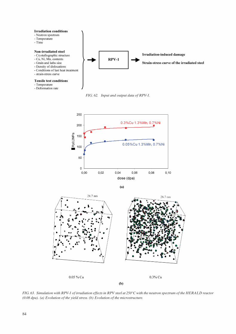
FIG. 62. Input and output data of RPV-1.
FIG. 63. Simulation with RPV-1 of irradiation effects in RPV steel at 250°C with the neutron spectrum of the HERALD reactor (0.08 dpa). (a) Evolution of the yield stress. (b) Evolution of the microstructure.
84

5. ASSESSMENT OF THE MECHANICAL PROPERTIES OF OPERATING RPVS
5.1. INTRODUCTION
The changes in material properties due to neutron irradiation are monitored by means of surveillance programmes. Every LWR pressure vessel operating in Western countries and the majority of WWER RPVs (WWER-440/213 and WWER-1000) have an ongoing RPV material radiation surveillance programme. To date, several hundred surveillance capsules have been removed from their host RPVs and tested. The results from these surveillance capsules have been used to develop heat-up and cool-down curves and to analyse all potential or postulated accident or transient conditions. The layout of surveillance programmes is standardized in most countries either in national standards and regulatory requirements or by adopting the American Standard ASTM.
The ASTM Standards are dominating for LWR RPVs. Parallel to this, there exist a few European EN Standards and activities in the European Structural Integrity Society are under way. A review of the ASTM Standards and other standards or recommendations has shown that only slight differences exist, which are not supposed to affect the general safety strategy. The standards for WWER surveillance programmes are given in Ref. [16] and updated in Ref. [17].
The material state of the RPV in the core beltline region at any time can be characterized by the initial properties and change in properties under service conditions depending on chemical composition, neutron exposure, temperature and time.
5.2. MECHANICAL PROPERTIES
In the unirradiated condition, the material behaviour is usually described on a much broader basis than in the irradiated condition. This is due to the fact that in irradiation channels of power reactors there is only limited space and, therefore, only a limited number of specimens, as many as urgently necessary, are irradiated in the frame of surveillance programmes.
The basic objective of a surveillance programme is to evaluate the material bounds for the safety assessment (fracture toughness curves have been derived for the irradiated state based on unirradiated data, adjusted on the basis of test results of irradiated Charpy specimens according to the ‘reference temperature concept’). In general, as detailed in Section 3, the following tests are performed:
— Tensile test;— CVN test;— Drop-weight test;— Fracture mechanics test.
In order to obtain representative and conservative data for the component, requirements exist for specimen sampling and specimen orientation.
5.3. RPV SURVEILLANCE PROGRAMMES
5.3.1. Surveillance programmes in accordance with US regulations
A set of rules for the reactor vessel material surveillance programmes, Appendix H to 10 CFR Part 50 [108], was published in the USA with the last revision in 1995. The significant points given in Appendix H are:
85

— That part of the surveillance programme conducted with the first capsule withdrawal must meet the requirements of ASTM E 185-82 [109] that is current on the issue date of the ASME Code to which the reactor vessel was purchased3;
— Surveillance specimen capsules must be located near the inside vessel wall in the beltline region, so that the specimen radiation history duplicates to the extent practicable within the physical constraints of the system, the neutron spectrum, temperature history and maximum neutron fluence experienced by the reactor vessel inner wall;
— A surveillance capsule withdrawal schedule must be submitted to and be approved by the US Nuclear Regulatory Commission (USNRC) prior to implementation;
— Each surveillance capsule withdrawal and the test results must be the subject of a summary report submitted to the USNRC.
There are a number of countries that follow US regulations, among them are Spain, Belgium, The Nether-lands, Sweden and Mexico. Appendix H makes reference to ASTM Standards, particularly to ASTM E 185. It describes the criteria that should be considered in planning and implementing surveillance tests programmes and points out precautions that should be taken to ensure that:
— Capsule exposures can be related to beltline exposures;— Materials selected for the surveillance programme are samples of those materials most likely to limit the
operation of the reactor vessel;— The tests yield results useful for the evaluation of radiation effects on the reactor vessel.
Surveillance test materials should be prepared, according to ASTM E185-82, from samples taken from the actual materials used in fabricating the beltline of the reactor vessel. It is also recommended in this standard that they should include one heat of the base metal and one butt weld (previous recommendations to include one weld HAZ have been deleted in the current standard), which should be selected for the surveillance programme with the highest adjusted reference temperature (ART) at the EOL.
ASTM E185-82 recommends that 18 Charpy unirradiated specimens be provided, of which a minimum of 15 specimens should be tested to establish a full transition temperature curve for each material (base metal, HAZ, weld metal). For the irradiated specimens, the minimum number of test specimens for each irradiation exposure set (capsule) should be as given in Table 19.
It is suggested that a greater quantity of the above specimens be included in the irradiation capsules whenever possible.
Surveillance capsules are suggested to be located within the reactor vessel so that the specimen irradiation history duplicates, as closely as possible, within the physical constraints of the system, neutron spectrum,
3 Although 10 CFR 50 references E 185-82, the ASTM has published a newer version designated E 185-02 (published in 2002). This recent version applies only to planning and design of surveillance programmes designed and built after the effective date of that practice. As part of that revision, a new practice, E 2215-02, “Practice for the Evaluation of Surveillance Capsules from Light-Water Moderated Nuclear Power Reactor Vessels”, was published in 2002 and covers the evaluation of test specimens and dosimetry from surveillance capsules.
TABLE 19. NUMBER OF IRRADIATED TEST SPECIMENS FOR EACH RADIATION EXPOSURE
Material Charpy TensionBase metal 12 3
Weld metal 12 3
HAZ* 12 —
* Note that E 185-02 does not include irradiation of HAZ specimens.
86

temperature history and maximum neutron fluence experienced by the reactor vessel. ASTM E 185-82 (and E 185-02) recommends that the surveillance capsule lead factors be in the range of one to three.
The capsule withdrawal schedule should permit monitoring of long time effects which are difficult to achieve in tests reactors. Table 20 from ASTM E 185-82 lists the recommended number of capsules and the withdrawal schedule for three ranges of predicted transition temperature shift.
5.3.2. Surveillance programmes in Germany
5.3.2.1. German standard KTA
In the early 1980s, the German Nuclear Safety Standards Commission, KTA, elaborated standards for fabrication and operation of German nuclear power plants. The proceedings concerning the monitoring of the irradiation behaviour of the RPV materials from LWRs in Germany are stipulated in the KTA Safety Standard 3203 [110].
5.3.2.2. Surveillance programmes
All German PWR nuclear power stations (except for the first three), built in the late 1960s and early 1970s, have a neutron fluence equal to 5 1022 n/m2 (E > 1 MeV) for a designed operation period of 32 EFPY. Due to large water gaps, the German BWRs have lower flux and a lower designed fluence after 32 EFPY.
In agreement with KTA 3203, the surveillance programmes of these power stations consist of three sets. The first one has to be tested in the unirradiated initial state for base line data, the second one at about half of the designed fluence and the third one at the designed life fluence or greater.
The number of materials tested in the surveillance sets depends on the design life fluence (Tables 21 and 22). For RPVs with a design life fluence of less than 1 1023 n/m2 (E > 1 MeV), only one base material has to be tested within the surveillance programme when the materials used for fabricating the RPV satisfy the specifications of KTA: KTA Rule 3201.1 Materials [111] and KTA Rule 3201.3 Fabrication [112].
A surveillance set consists of specimens, temperature monitors and fluence detectors all packed in a capsule fabricated of thin austenitic stainless steel plate according to the collapsed can principle. The capsules
TABLE 20. MINIMUM RECOMMENDED NUMBER OF SURVEILLANCE CAPSULES AND THEIR WITHDRAWAL SCHEDULE (IN EFPY)
Predicted transition temperature shift at vessel inside surface
56ºC (100ºF) >56ºC (>100ºF) 111ºC (200ºF)
>111ºC (>200ºF)
Minimum number of capsule withdrawal sequence
3 4 5
First 6a 3a 1.5a
Second 15b 6c 3d
Third EOLa 15b 6c
Fourth EOLa 15b
Fifth EOLa
a At the time when the accumulated neutron fluence of the capsule exceeds 5 1022 n/m2 or at the time when the highest predicted RTNDT of all encapsulated materials is approximately 28ºC (50ºF), whichever comes first.
b At the time when the accumulated neutron fluence of the capsule corresponds to the approximate EOL fluence at the reactor vessel inner wall location, whichever comes first.
c At the time when the accumulated neutron fluence of the capsule corresponds to the approximate EOL fluence at the reactor vessel 1/4T location, whichever comes first.
d At the time when the accumulated neutron fluence of the capsule corresponds to a value midway between that of the first and third capsules.
87

are located between the core barrel and the RPV along the entire core length, as shown in Fig. 64. According to the stipulations in the KTA, and depending on the capsule location, the lead factor is between 1.5 and 12. The major part of the surveillance capsules of the operating German nuclear power stations were irradiated with a lead factor of about five, in order to receive individual surveillance results at an early time of operation of the power station. The credibility and transferability of the results achieved with different flux in the concerned range has been validated by experiments [113, 114].
Besides the specimens for the surveillance programme, an approximately 1.5 m long section of the fabricated test coupon has to be stored as archive material. All steps of the performance of a surveillance programme, the fabrication of the test coupon and the capsules, testing of the unirradiated specimens, irradi-ation, withdrawal, and testing and evaluation of the irradiated specimens have to be documented. The performance and documentation have to be proofed by an independent inspector.
There are differences between ASTM and KTA in the requirements of the surveillance programmes, such as the number of the specimen sets and the removal schedule, archive material instead of optional specimens in the standard capsules, and the value of leading factors. These differences are justified by the fact that the enveloping ART for the German RPVs, RTLimit, is not higher than 40°C due to a low designed fluence of 5 1022 n/m2.
5.3.3. Surveillance programme in France
The material surveillance programme specified in RSE-M [115] is similar to the US programme discussed above. Capsules are removed from the plants and the specimens subjected to Charpy testing. The measured shifts in the Charpy transition temperatures are compared with the predicted values. Unlike other countries, there is a specified limit for the lead factor (less than three). The archive material is stored for future use.
Some changes in the French surveillance programmes (rearrangement of the capsules, new material in the capsules, laboratory tests, etc.) are being studied to support a possible life extension from 40 to 60 years.
TABLE 21. NUMBER OF TEST SPECIMENS FOR A DESIGN FLUENCE LESS THAN 1 1023 n/m2 (E > 1 MEV), KTA 3203
Test specimen set no.
Charpy V specimens Tensile test specimensWithdrawal
BM WM BM WM
1 12 12 3 3 Non-irradiated
2 12 12 3 3 50% Design fluence
3 12 12 3 3 100% Design fluence
BM: base metalWM: weld metal
TABLE 22. NUMBER OF TEST SPECIMENS FOR A DESIGN FLUENCE GREATER THAN 1 ´ 1023 n/m2 (E > 1 MEV), KTA 3203
Test specimen set no.
Charpy V specimens Tensile test specimensWithdrawal
BM I BM II WM BM I BM II WM
1 12 12 12 3 3 3 Non-irradiated
2 12 12 12 3 3 3 50% Design fluence
3 12 12 12 3 3 3 100% Design fluence
BM: base metalWM: weld metal
88

5.3.4. Surveillance programme in Japan
Currently, six capsules are inserted into each Japanese PWR vessel between the core and the pressure vessel wall. Each capsule is made of stainless steel and contains CVN, tensile and fracture toughness specimens, as well as neutron dosimeters and thermal monitors. The specimens were machined from the representative materials of which the RPV was fabricated. These materials include base metal from the lower and/or interme-diate shells of the vessel, weld metal by an automatic submerged arc welding process, and HAZ material. Two grades of base metal SA533 Gr.B Cl. 1 plate and SA508 Cl. 3 forging have been used for shells of Japanese PWR vessels.
The surveillance capsules are periodically removed and all the surveillance tests are performed in accordance with the JEAC 4201, which is similar to the ASTM E185. CVN impact tests are performed to obtain a full transition curve, and the tensile tests are conducted from room temperature through 300ºC. Fracture toughness tests are carried out using 12.7 mm thick compact specimens (1/2CT) in both the transition temperature region and the upper shelf region. In the latter case, the unloading compliance method is used for obtaining a J-a curve of the material in accordance with ASTM E 1820.
5.3.5. Surveillance programme in WWER RPVs
The requirements for the WWER material surveillance programmes are given in Ref. [16] and updated in Ref. [17]. They have been applied to WWER-440/213 and WWER-1000 nuclear power plants. The oldest design type, the WWER-440/230, was not supplied with a surveillance programme. Listed below are some features of WWER-440/213 surveillance programmes:
FIG. 64. Locations of RPV surveillance specimens in German RPVs.
89

— The specimens are put into stainless steel containers, six tensile or two/three Charpy size specimens in one container. The containers are connected into a chain consisting of 10 or 20 containers and placed adjacent to the beltline area;
— Six sets of specimens are located in each unit; one set (consisting of two chains) is at each corner of the hexagon core;
— The planned withdrawal interval is usually one, three, five and ten years;— The specimens are located on the outer wall of the core barrel, where the high lead factor (~6 for a core
with dummy assemblies and ~18 for the full core for weld metal) is obtained;— In addition to the ‘irradiated’ specimens, specimens for the thermal ageing monitoring of RPV materials
are included in surveillance programmes. Two sets are located above the core in front of the upper (outlet) nozzle ring. These sets are usually removed after five and ten years of operation.
For the WWER-1000, the specimens are located in the upper part of the core (Fig. 65) with the consequence of certain disadvantages and irradiation conditions which are somewhat different from those of the RPVs as follows:
— The spectral index of surveillance specimens is different from that of the RPV wall;— The neutron fluence rate (flux) gradient is very high in the surveillance positions. The design of the surveil-
lance capsule assembly results in a notable radial variation of the neutron fluence in the assembly (up to a factor of two);
— On the basis of calculation, the irradiation temperature of surveillance specimens could be 300–310ºC, i.e. 10–20ºC higher than the RPV wall temperature.
The surveillance programmes for the three WWER-1000 pressure vessels constructed in the Czech Republic have been modified as follows. The specimen specification was extended to include dynamic fracture toughness specimens. The specimens have been grouped in a flat box and located symmetrically in the core region near the inner vessel wall where the lead factor is 1.5–2.
5.4. DETERMINATION OF NEUTRON EXPOSURE
The neutron exposure has to be determined for the surveillance specimens and the RPV. The calculation is focussed on the determination of the lead factor, which represents the ratio of exposure of the surveillance
FIG. 65. Location of surveillance capsules in a WWER-1000 RPV.
90
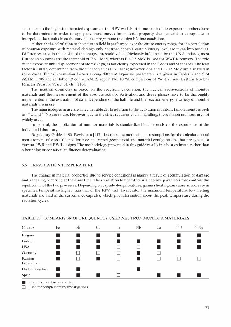
specimens to the highest anticipated exposure at the RPV wall. Furthermore, absolute exposure numbers have to be determined in order to apply the trend curves for material property changes, and to extrapolate or interpolate the results from the surveillance programme to design lifetime conditions.
Although the calculation of the neutron field is performed over the entire energy range, for the correlation of neutron exposure with material damage only neutrons above a certain energy level are taken into account. Differences exist in the choice of the energy threshold value. Obviously influenced by the US Standards, most European countries use the threshold of E 1 MeV, whereas E 0.5 MeV is used for WWER reactors. The role of the exposure unit ‘displacement of atoms’ (dpa) is not clearly expressed in the Codes and Standards. The lead factor is usually determined from the fluence values E 1 MeV; however, dpa and E 0.5 MeV are also used in some cases. Typical conversion factors among different exposure parameters are given in Tables 3 and 5 of ASTM E706 and in Table 19 of the AMES report No. 10 “A comparison of Western and Eastern Nuclear Reactor Pressure Vessel Steels” [116].
The neutron dosimetry is based on the spectrum calculation, the nuclear cross-sections of monitor materials and the measurement of the absolute activity. Activation and decay phases have to be thoroughly implemented in the evaluation of data. Depending on the half life and the reaction energy, a variety of monitor materials are in use.
The main isotopes in use are listed in Table 23. In addition to the activation monitors, fission monitors such as 238U and 237Np are in use. However, due to the strict requirements in handling, those fission monitors are not widely used.
In general, the application of monitor materials is standardized but depends on the experience of the individual laboratory.
Regulatory Guide 1.190, Revision 0 [117] describes the methods and assumptions for the calculation and measurement of vessel fluence for core and vessel geometrical and material configurations that are typical of current PWR and BWR designs. The methodology presented in this guide results in a best estimate, rather than a bounding or conservative fluence determination.
5.5. IRRADIATION TEMPERATURE
The change in material properties due to service conditions is mainly a result of accumulation of damage and annealing occurring at the same time. The irradiation temperature is a decisive parameter that controls the equilibrium of the two processes. Depending on capsule design features, gamma heating can cause an increase in specimen temperature higher than that of the RPV wall. To monitor the maximum temperature, low melting materials are used in the surveillance capsules, which give information about the peak temperature during the radiation cycles.
TABLE 23. COMPARISON OF FREQUENTLY USED NEUTRON MONITOR MATERIALS
Country Fe Ni Cu Ti Nb Co 238U 237Np
Belgium
Finland
USA
Germany
Russian Federation
United Kingdom
Spain
Used in surveillance capsules. Used for complementary investigations.
91

ASTM E 185 [109] gives guidance about temperature monitoring and allows a deviation of 14 K from the expected capsule exposure temperature. Regarding application of surveillance data to the RPV wall, U.S. Reg. Guide 1.99, Revision 2 [90] requires a matching in temperature of 14 K. A more restrictive guidance for evaluating the irradiation temperature is contained in KTA 3203 [110]; deviations in temperature from the average coolant temperature of more than 5 K have to be considered in the determination of the shift in transition temperature.
From experience, the melt monitors do not give reliable information about the long term specimen temperature since short time overheating due to plant specific measures during startup or shutdown can cause melting of the temperature monitors without influencing the long range material behaviour. Therefore, melt monitors are only considered to give limits on the upper temperature bound. ASTM E 1214 [118] and KTA 3203 [110] give examples for alloys and the corresponding melting temperature.
The new USNRC and ASTM embrittlement correlations for power reactors take into account the effect of the irradiation temperature. These correlations attribute the temperature dependence to the stable matrix defect term in the equations, consistent with current understanding. It is established that an increase in the transition temperature shift of 0.6 degree per degree lower Tc at the median values of the variables is a reasonable approximation of the temperature effect. Tc is taken as the cold leg temperature for PWRs and as the recirculation temperature for BWRs.
For WWER reactors, a method was developed to determine the specimen temperature from changes in properties of diamond which was used as a monitor material in irradiation capsules. However, this method is non-representative for surveillance specimen information. Currently, low melting alloys are being used to determine the maximum temperature in the capsules during irradiation.
Due to the different capsule design and capsule locations in the reactor, there are great differences in the methodologies to evaluate the irradiation temperature. The existing standards only give recommendations for certain methods. The evaluation of adequate temperature of surveillance specimens and the RPV wall with regard to the transferability of the surveillance results is part of the safety analysis.
5.6. CURRENT APPROACH FOR DETERMINATION OF RPV EMBRITTLEMENT
As has been seen in previous sections, the steels used for the reactor vessel become progressively brittle throughout the service lifetime of the component as a result of the effects of the neutron radiation to which they are exposed. This progressive degradation must be known in order to guarantee the structural integrity of the vessel throughout its service lifetime.
There are different parameters that make it possible to evaluate and quantify vessel degradation. These parameters are fundamentally two: USE and RTNDT. The initial values of RTNDT are obtained by means of Charpy and drop-weight tests, while increases in RTNDT and the value of USE are measured exclusively by means of Charpy tests. For WWER reactors, the Tk reference temperature is based only on Charpy test results for both unirradiated and irradiated material.
RTNDT tends to increase throughout the service lifetime of the reactor, while USE tends to decrease.There are two ways of estimating these parameters throughout the service lifetime of the reactor. On the
one hand, the value of these parameters may be calculated by means of generic empirical models, to be explained below, developed on the basis of data from the testing of irradiated materials in experimental reactors (approach used mainly in the Russian Federation), along with data from the irradiation of surveillance capsules in commercial power reactors. On the other hand, the values of these parameters may be obtained from the analysis of surveillance capsules from the reactor being studied. The values obtained in this way allow us to re-adjust the theoretical values. Surveillance data are not always available, in which case it will be necessary to use the generic models.
In short, the results obtained from evaluation of these parameters make it possible to guarantee that the reactor is operating with a certain degree of safety. These results may also contribute to extending the service lifetime of the plants, either by ensuring compliance with vessel toughness requirements and providing the information required for extending the plant operating licence beyond its design lifetime, or by establishing bases for possible annealing of the vessel.
92

5.6.1. Initial reference temperature
In accordance with the ASME Code, Section III, NB 2331 [119], RTNDT is defined as follows:
RTNDT = NDTT if NDTT T68(0.89) – 33ºC (13)
RTNDT = T68(0.89) – 33ºC if T68(0.89) – 33ºC NDTT (14)
T68 (0.89) is the minimal temperature for which 68 J of energy are absorbed in the Charpy test or the temperature at which 0.89 mm of minimal lateral expansion occurs, if higher than the first.
NDTT is the NDT temperature, and is defined as the maximum temperature at which a test specimen breaks in a drop-weight test performed in accordance with the ASTM E-208 [120] test method.
The parameter analogous to RTNDT in countries using WWER-type reactors is the transition temperature Tk, which is only obtained from Charpy tests. This temperature must meet the following requirements for the initial condition:
— The average value of impact energy should not be lower than the values shown in Table 24;— At temperature Tk0, none of the three samples tested should show a resistance to impact below 70% of the
values included in Table 24;— The average value of resistance to impact at temperature Tk0 + 30 K should not be below 1.5 times the
value shown in Table 24;— The proportion of ductile fracture of each sample at temperature Tk0 + 30 K should not be below 50%.
5.6.2. Transition temperature shift
There are different empirical models, developed by different countries, which predict the evolution of RTNDT as a consequence of irradiation. Each of these models has been developed for specific materials, as a result of which they do not readily apply to any specific type of reactor. Consequently, care should be taken when applying these models.
All these models have been obtained following decades of study aimed at identifying the factors having the greatest relevance as regards the change in RTNDT, generating expressions with the following general form:
RTNDT = A(chemical composition, irradiation temp., flux)n + constant (15)
where:
—RTNDT is the irradiation-induced change experienced by RTNDT;— is neutron fluence, raised to exponent n;— A is a coefficient that depends on chemical composition (especially the content of residual elements) on
irradiation temperature and on neutron flux.
TABLE 24. REFERENCE VALUES FOR THE CALCULATION OF Tk0
Rp0.2 (MPa) Absorbed energy (J)
300 23
300–400 31
400–550 39
550–690 47
93
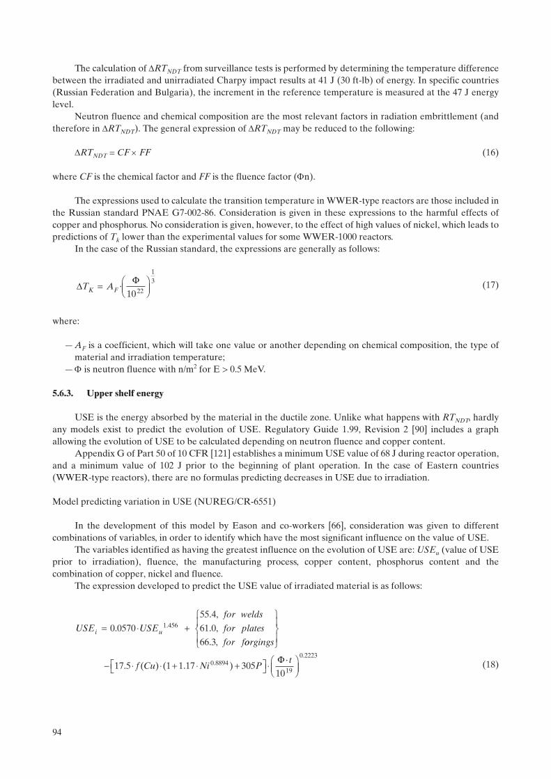
The calculation of RTNDT from surveillance tests is performed by determining the temperature difference between the irradiated and unirradiated Charpy impact results at 41 J (30 ft-lb) of energy. In specific countries (Russian Federation and Bulgaria), the increment in the reference temperature is measured at the 47 J energy level.
Neutron fluence and chemical composition are the most relevant factors in radiation embrittlement (and therefore in RTNDT). The general expression of RTNDT may be reduced to the following:
RTNDT = CF FF (16)
where CF is the chemical factor and FF is the fluence factor (n).
The expressions used to calculate the transition temperature in WWER-type reactors are those included in the Russian standard PNAE G7-002-86. Consideration is given in these expressions to the harmful effects of copper and phosphorus. No consideration is given, however, to the effect of high values of nickel, which leads to predictions of Tk lower than the experimental values for some WWER-1000 reactors.
In the case of the Russian standard, the expressions are generally as follows:
(17)
where:
— AF is a coefficient, which will take one value or another depending on chemical composition, the type of material and irradiation temperature;
— is neutron fluence with n/m2 for E > 0.5 MeV.
5.6.3. Upper shelf energy
USE is the energy absorbed by the material in the ductile zone. Unlike what happens with RTNDT, hardly any models exist to predict the evolution of USE. Regulatory Guide 1.99, Revision 2 [90] includes a graph allowing the evolution of USE to be calculated depending on neutron fluence and copper content.
Appendix G of Part 50 of 10 CFR [121] establishes a minimum USE value of 68 J during reactor operation, and a minimum value of 102 J prior to the beginning of plant operation. In the case of Eastern countries (WWER-type reactors), there are no formulas predicting decreases in USE due to irradiation.
Model predicting variation in USE (NUREG/CR-6551)
In the development of this model by Eason and co-workers [66], consideration was given to different combinations of variables, in order to identify which have the most significant influence on the value of USE.
The variables identified as having the greatest influence on the evolution of USE are: USEu (value of USE prior to irradiation), fluence, the manufacturing process, copper content, phosphorus content and the combination of copper, nickel and fluence.
The expression developed to predict the USE value of irradiated material is as follows:
(18)
DF
T AK F= ÊËÁ
ˆ¯
·10 22
13
USE USE
for welds
for plates
for fi u= ◊ +0 0570
55 4
61 0
66 3
1 456.
. ,
. ,
. ,
.
oorgings
f Cu Ni P
ÏÌÔ
ÓÔ
¸˝Ô
Ô
- ◊ ◊ + ◊ +ÈÎ ˘ ◊17 5 1 1 17 3050 8894. ( ) ( . ). F◊◊ÊËÁ
ˆ¯
t
1019
0 2223.
94

where:
— USE is in ft-lb;— Cu, Ni and P are in mass percent;—t, fluence rate (flux) times the time of exposure, is neutron fluence in n/cm2.
As may be appreciated, consideration is given in this new model to variables other than those already taken into account in the model included in Regulatory Guide 1.99, Revision 2. These variables are phosphorus content and the manufacturing process. Furthermore, a term with a hyperbolic tangent having a saturation effect is included, this occurring with excessive amounts of copper (>0.3%).
In addition to the expression shown above, NUREG/CR-6551 contains additional correlations, such as the following practical case in which the USE decrement is related to increasing reference temperature (RTNDT).
USEu – USEi = 2.51 + 0.147 RTNDT (19)
where RTNDT is in ºF and USE in ft-lb.
For this last correlation (Eq. (19)), Fig. 66 shows the comparison between the measured and theoretical values of USE when applied to the Spanish PWR surveillance data. This comparison shows that the simplified correlation of Eq. (19) provides a good result for this set of surveillance data.
5.6.4. New prediction models for RTNDT
In recent years, new correlations have been developed for the calculation of RTNDT. These new correla-tions have been developed using a large amount of currently available data. Furthermore, consideration has been given to new knowledge of embrittlement mechanisms.
Different independent variables have been taken into account in developing these correlations. These variables are: the chemical composition of the material, irradiation temperature, fluence, flux, material, reactor type, sample orientation and the manufacturing process (welding, forging, rolling). The influence of each of these variables on RTNDT is underlined in the more recent correlations developed in the USA.
f CuCu
( ) tanh.
.= + ◊
-ÊËÁ
ˆ¯
ÈÎÍ
˘˚˙
12
12
0 1380 0846
FIG. 66. Theoretical versus measured values of USE using the Eason correlation between transition temperature shift and USE change given in Eq. (19).
95

New draft correlations for the calculation of RTNDT were developed by Eason et al. for the USNRC, originally published in Ref. [122] and subsequently published in Ref. [123]. Additionally, there are similar corre-lations developed by ASTM and published in ASTM E 900-02 [124]. These models are obtained by means of adjusting the available data with non-linear least squares techniques.
The main differences between those USNRC and ASTM correlations is the fact that the expression developed by the ASTM does not include the phosphorus term, which does appear in the draft 2001 correlation developed for the USNRC. Additionally, a bias term is included in the draft 2001 USNRC correlation to account for an increased shift when irradiation time is greater than 97 000 h. More recent trend curve developments by Eason for the USNRC have resulted in elimination of that bias term, and inclusion of manganese as a variable [178].
In none of these correlations has consideration been given to materials corresponding to weld HAZ, since these materials are rarely the most limiting, because of their low initial RTNDT values and high toughness.
These correlations provide theoretical predictions of RTNDT for different fluence values, and must be compared to the values obtained from surveillance programmes. If there is any discrepancy between the experi-mental and theoretical data, an analysis should be performed to establish the actual conditions of irradiation, since the discrepancy will probably be due to incorrect input data.
Different correlations have been developed in different countries. Sections 6.4.1 to 6.4.3 describe the more recent embrittlement trend curves developed in the USA and Germany. Relevant also are the FIM and FIS formulas used in France that consider the effect of Cu, Ni and P, and the Japanese embrittlement predictive equations that include Cu, Ni and P for base material and Cu, Ni and Si for welds.
5.6.4.1. USNRC model for RTNDT
The expression developed in 2001 by Eason et al. for the prediction of RTNDT (T41J) [123] included three terms, one to account for matrix damage, the second for embrittlement due to irradiation-induced Cu-enriched precipitates, and a third bias term to account for increased embrittlement when the time of irradiation is greater than 97 000 h. The matrix damage term included variables for irradiation temperature (based on inlet coolant temperature), phosphorus content, and fluence (E > 1 MeV). The precipitation term included variables for nickel and copper contents, a flux-time term and fluence. The first and second terms included coefficients of different values for plates, welds, and forgings.
As noted in Section 5.6.4, more recent trend curve developments by Eason, Odette, Nanstad and Yamamoto for the USNRC have resulted in elimination of that bias term and inclusion of a manganese term.
5.6.4.2. E 900-02 model for RTNDT
The expression recommended by the ASTM for RTNDT in ºF is somewhat similar to that of the Eason model, but does not include phosphorus nor a bias term. It is calculated as follows [124]:
RTNDT = TTS = SMD + CRP (20)
where:
and
SMD AT
CRP B Ni
c
= ◊+( )
È
ÎÍÍ
˘
˚˙˙◊ ( )
= ◊ + ◊
exp
.
.
.
20730
460
1 2 106
0 5076
1
F
1173ÈÎ ˘ ◊ ( ) ◊ ( )F Cu G F
A B= ¥ =-6 70 10 18.
234, welds
128, forgings
208, Combustiion Engineering plates
ÏÌÔ
ÓÔ
¸˝Ô
Ô
96

subject to
— Tc (coolant temperature) is in ºF;— Cu and Ni are in percentage in weight;
— is neutron fluence in .
5.6.4.3. KTA approach
In accordance with the German regulations [110], the aim of the surveillance programme is to evaluate a fracture mechanics curve (KIc,T-Curve) for the safety assessment of the RPV. This can be achieved according to the RTNDT Concept (RTNDT adjusted = RTNDT initial + ?T41) or according to the Fracture Mechanics Concept, for example by determination of T0 according to ASTM E 1921.
If the neutron fluence is lower than 1 1021 n/m2 (E > 1 MeV), no toughness degradation due to irradiation has to be considered in the safety assessment. For RPVs with a design neutron fluence in the range of 1 1021 n/m2 up to 1 1023 n/m2 (E > 1 MeV) an RTNDT limit = 40°C can be used as RTNDT adjusted for those materials for which no surveillance data exists (Fig. 67). In the case of existing measured data, these can be used too. If two sets or more exist, an interpolation or extrapolation of the DBTT shift, in general ?T41 is allowed by using a suitable best fit function, preferably a potential function like A n.
G FF( ) = +( ) -È
ÎÍ
˘
˚˙
12
12
18 24
1 052tanh
log .
.
F CuCu wt
Cu Cu wt( ) =
£
-( ) >
ÏÌÔ
ÓÔ
¸˝Ô
Ô
0 0 072
0 072 0 0720 577
, . %
. , . %.
Cuwt
max
. %,=
0 25 for welds with Linde 80 or Linde 0091 flux
00.305 , for others weldswt%ÏÌÓ
¸˝˛
n
cm2
FIG. 67. RTNDT adjusted for German PWR and BWR base and weld materials with limited Cu content (Cu < 0.12) together with the enveloping RTLimit.
97

For the German nuclear power stations which are presently in operation, almost all irradiation surveillance programmes are completed and evaluated. Therefore, all RTNDT values were determined to establish a reference temperature limit for the brittle failure assessment. The evaluation of this data base (Fig. 67) confirmed an RTNDT value of 40°C as an upper limit for RPV materials according to the KTA specification and for neutron fluences to l023 n/m2 (E > 1 MeV). This limiting curve is established in the updated issue of KTA 3203 [110] as RTLimit.
5.7. VESSEL BOAT SAMPLING
There are some old plants that have no surveillance specimens in the RPV to monitor irradiation embrit-tlement. For these plants, the taking of so-called ‘boat samples’ or templates was proposed. Up to now, the sampling has only been used for RPVs without cladding.
This procedure is used widely for the Russian design WWER-440/230 RPV [125]. For these RPVs, besides the lack of surveillance programmes, the archive material to perform supplementary evaluation is also not available. The evaluation of the vessel material status in terms of Tk was based on an empirical relationship using the assumed chemical composition. Later, the chemical composition was verified by the analysis of scraps taken from the vessel surface.
Since 1991, boat samples were taken from all uncladded WWERs (several times for several of them) to verify the material status (the comparison of experimental data to the predicted values determined by the Russian standards), and the effectiveness of the annealing technology applied for the recovery of the RPV. The mechanical testing of subsize Charpy specimens was used.
The typical scheme for the boat sample cutting is presented in Fig. 68 [125]. Some of the samples were used for the material embrittlement assessment before annealing, and some for the annealing effectiveness evaluation. In some cases, a few boat samples could be used for additional accelerated irradiation, to provide information about the re-embrittlement rate during post-annealing reactor operation.
The 3 mm 4 mm 27 mm subsize Charpy specimens are machined from the base metal and 5 mm 5 mm 27 mm specimens from the RPV welds. The shape of subsize specimens and their notch orientation are presented in Figs 69 and 70.
FIG. 68. Scheme of boat sampling for KZL-2 RPV.
98

Correlations between standard and subsize Charpy specimens have been developed by Russian organiza-tions since the beginning of the 1990s. They performed experiments devoted to determining those dependencies and their relation to the irradiation condition [125].
Tk (10 × 10 × 55) = Tk (3?4?27) + 65 K (21)
Tk (10 × 10 × 55) = Tk (5?5?27.5) + 50 K (22)
However, in later experiments, an increase in the constant of the correlation has been observed, and therefore a raise of Tk.
The boat samples can also be used for the leading assessment of RPV material condition. Research is being undertaken in the Russian Federation with subsize specimens irradiated in a commercial operating WWER with channels for the surveillance specimens.
5.8. ANNEALING AND RE-IRRADIATION
5.8.1. Annealing
It has been demonstrated that annealing of irradiated RPV materials restores the mechanical properties [126]. The degree of recovery for a given steel depends on the time and the temperature at which annealing is performed. Dependencies of Charpy curve shift recovery on temperature and time of annealing, fluence and impurity contents were validated. The dependency of the residual shift after annealing on phosphorus content in WWER materials was established. It was verified that phosphorus plays one of the main roles in both radiation embrittlement and annealing processes.
Annealing of 15 WWER-440 RPVs in the Russian Federation, Armenia, Bulgaria, Slovakia and Finland was carried out successfully. There are seven WWER-440 RPVs still in operation after annealing, with current plans to close one other in the next few years.
Embrittlement mechanisms in Western- and Russian-type RPV steels are somewhat different, because the main factor in the former steels is copper (USNRC Reg. Guide 1.99 Revision 2), while it is phosphorus in the WWER-440 steels (Russian Standard PNAE G-7-002-86).
5.8.1.1. Annealing methods
There are two techniques in the thermal annealing process:
FIG. 69. Boat sampling of base metal. FIG. 70. Boat sampling of weld metal.
99

— The wet annealing technique uses primary coolant and nuclear heat or primary pump heat. It was the first method used in RPV annealing (US Army SM-1A and Belgian BR-3). This technique is easy to implement because usually only the fuel must be removed from the RPV, but, unfortunately, it can only be effectively utilized in reactors which have a low service temperature. RPVs are not designed to stand the pressure of water at higher temperatures and the critical point of water is reached already at 374ºC (pcrit = 219 bar). Due to the very limited recovery achieved, wet annealing with water is not a practical solution for power reactors as it needs to be repeated frequently;
— Dry annealing can be carried out by heating the RPV by electric resistance radiant heaters, magnetic induction heating, circulated ambient pressure superheated steam, direct fired combustion heating and indirect combustion radiant heating. Nevertheless, annealing by means of electric resistance radiant heating offers the best control of the heated area. The most common temperatures in dry annealing are between 430 and 503ºC, and are held for about 150 h.
One of the greatest risks in recovery annealing is exceeding the acceptable stress level, resulting in residual strains. In case of annealing only one ring weld, this can be avoided using sufficiently low heat-up and cool-down rates and controlling temperature gradients. In WWER-440 RPVs, the calculations have shown the maximum rate to be about 20ºC/h if the height of the heated zone is optimal. If the base metal also needs to be recovered, or if the RPV contains longitudinal welds, the situation will essentially be more complicated.
References on this subject can be found in the US Regulatory Guide 1.162 [88], the Russian Regulatory Guide [17] and ASTM Standard E 509-86 [127].
US Regulatory Guide 1.162 describes a format and content acceptable to the USNRC for the thermal annealing report to be submitted to the USNRC for describing the licencee’s plan for thermal annealing a reactor vessel. This guide also describes the thermal annealing results report that is required by 10 CFR 50.66 [128] to be submitted after the thermal annealing and the alternative methods that are acceptable to the USNRC for determining the recovery of fracture toughness after this process. It also estimates the degree of post-annealing re-embrittlement expected during subsequent plant operation.
General guidance for in-service annealing may be found in ASTM Standard E 509-86 [127]. It contains general procedures for conducting an in-service thermal anneal of a reactor vessel and for demonstrating the effectiveness and degree of recovery. ASTM Standard E 509-86 also provides direction for a post-anneal vessel radiation surveillance programme.
5.8.2. Re-irradiation
The residual lifetime of annealed vessels is determined by their re-embrittlement behaviour. Re-embrit-tlement behaviour [129] is usually described by using the vertical, lateral or conservative shift of the transition temperature, as shown in Fig. 71.
FIG. 71. Scheme of embrittlement of RPV under re-irradiation.
100
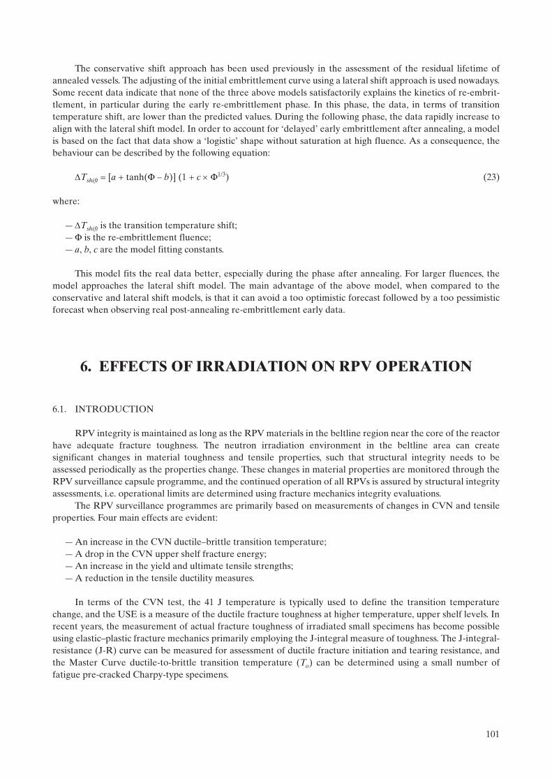
The conservative shift approach has been used previously in the assessment of the residual lifetime of annealed vessels. The adjusting of the initial embrittlement curve using a lateral shift approach is used nowadays. Some recent data indicate that none of the three above models satisfactorily explains the kinetics of re-embrit-tlement, in particular during the early re-embrittlement phase. In this phase, the data, in terms of transition temperature shift, are lower than the predicted values. During the following phase, the data rapidly increase to align with the lateral shift model. In order to account for ‘delayed’ early embrittlement after annealing, a model is based on the fact that data show a ‘logistic’ shape without saturation at high fluence. As a consequence, the behaviour can be described by the following equation:
Tshift = [a + tanh(F – b)] (1 + c F1/3) (23)
where:
—Tshift is the transition temperature shift;—F is the re-embrittlement fluence;— a, b, c are the model fitting constants.
This model fits the real data better, especially during the phase after annealing. For larger fluences, the model approaches the lateral shift model. The main advantage of the above model, when compared to the conservative and lateral shift models, is that it can avoid a too optimistic forecast followed by a too pessimistic forecast when observing real post-annealing re-embrittlement early data.
6. EFFECTS OF IRRADIATION ON RPV OPERATION
6.1. INTRODUCTION
RPV integrity is maintained as long as the RPV materials in the beltline region near the core of the reactor have adequate fracture toughness. The neutron irradiation environment in the beltline area can create significant changes in material toughness and tensile properties, such that structural integrity needs to be assessed periodically as the properties change. These changes in material properties are monitored through the RPV surveillance capsule programme, and the continued operation of all RPVs is assured by structural integrity assessments, i.e. operational limits are determined using fracture mechanics integrity evaluations.
The RPV surveillance programmes are primarily based on measurements of changes in CVN and tensile properties. Four main effects are evident:
— An increase in the CVN ductile–brittle transition temperature; — A drop in the CVN upper shelf fracture energy; — An increase in the yield and ultimate tensile strengths;— A reduction in the tensile ductility measures.
In terms of the CVN test, the 41 J temperature is typically used to define the transition temperature change, and the USE is a measure of the ductile fracture toughness at higher temperature, upper shelf levels. In recent years, the measurement of actual fracture toughness of irradiated small specimens has become possible using elastic–plastic fracture mechanics primarily employing the J-integral measure of toughness. The J-integral-resistance (J-R) curve can be measured for assessment of ductile fracture initiation and tearing resistance, and the Master Curve ductile-to-brittle transition temperature (To) can be determined using a small number of fatigue pre-cracked Charpy-type specimens.
101

The irradiated change in mechanical properties is a result of microstructural features resulting from high energy neutrons impacting the RPV materials. There are three main embrittlement mechanisms that are manifested through fine-scale microstructural changes:
— Matrix hardening resulting from irradiation-induced point defects inhibiting dislocation movement;— Hardening modelling resulting from the clustering of key elements (such as copper, phosphorus, nickel,
manganese, etc.) creating nanometer-size defects which also impede dislocation motion;— Non-hardening embrittlement occurring as certain elements (such as phosphorus) collect at grain
boundaries resulting in intergranular fracture.
Hardening increases can be measured from the tensile specimens in surveillance programmes, so that contributions from hardening embrittlement can be separated from non-hardening damage. The fracture surfaces can also be investigated to resolve relative amounts of transgranular and intergranular fracture.
This section is focused on the changes in material properties and how they impact RPV operation. Since most plant operation involves normal operation, which includes periodic startup and shutdown cycles, most structural integrity concerns are focused in terms of heat-up and cool-down pressure–temperature (P–T) controls. These controls constrain the plant operator to work within a window defined at the lower side by a minimum pressure for maintaining a net positive suction head to prevent cavitation and damage to pump impellers; at the upper end, controls are established by non-brittle structural integrity requirements. As irradiation to the RPV proceeds, the shift in transition temperature due to irradiation reduces the width of the operating ‘window’ as can be seen in Fig. 72. If the shift in transition temperature caused by irradiation is suffi-ciently large, the operating lifetime of the RPV can be constrained. The determination of the P–T limits is performed using deterministic analyses as will be described later. Other safety system requirements related to these P–T limits may exist for some plants, such as low temperature overpressure protection (LTOP) for PWRs.
Evaluations for accident conditions considered, both in design and outside design (e.g. PTS for PWRs and Russian-design WWER vessels), require further integrity studies, which can be either deterministic or probabil-istic. The integrity methodologies used worldwide are described later. Some issues associated with normal operation P–T limits result from the small operating window that operators have to follow due to restrictions from pump seal and cavitation considerations, as well as BWR hydro and leak test limitations at temperatures near or higher than 100C. Other operating restrictions can result in long heat-up times to meet specific P–T limit requirements, which result in an economic burden.
Validation of the current structural integrity approaches has been shown through the many years of safe operation of LWR vessels. There have not been any vessel failures. Additionally, there have been several large scale experiments performed to further validate the integrity of RPVs.
FIG. 72. Schematic diagram showing the irradiation-induced shift in operating P–T curves and operating window.
102

6.2. PARAMETERS GOVERNING RPV INTEGRITY
Structural integrity is determined using three main elements:
— The material fracture toughness, which is a function of the operating environment, can change significantly for some materials during the lifetime of the RPV;
— The mechanical and thermal stresses experienced during normal operating and severe accident transients;— The size and potential growth of defects postulated (or measured) to be present in the RPV structure.
Irradiation exposure significantly affects material fracture toughness, although there is an attendant increase in the yield strength of the RPV steel, which may have second or third order effects on the actual loads and projected growth of defects. In terms of assessing integrity during normal operation, a reference defect is assumed to be present at either the inside or outside of the RPV wall, and the applied stresses are dependent on the operating transients involved. The most common normal operation transients are heat-up and cool-down, and the maximum operating pressure is calculated as a function of temperature using a lower bound fracture toughness curve indicative of the degree of embrittlement experienced by the RPV. The size of the postulated defects, and the manner in which the lower bound fracture toughness curve is defined, varies somewhat throughout the world, but the integrity approach is fundamentally the same. Differences in the required regulatory margins can also vary.
Gerard [130] has conducted a thorough review of the integrity methods and regulatory requirements through about 1995 for most European countries, the Russian Federation and the USA (which also includes those countries that primarily follow US regulations). The key structural integrity elements discussed in Ref. [130] are reviewed in this report and updated to include changes and additional procedures in other countries throughout the world. Documentation of the numbers and operating LWR plant types from each country were derived from the IAEA Reference Data Series No. 2 [131], and the results are shown in Table 25. The structural
TABLE 25. CATEGORIZATION BY COUNTRY OF STRUCTURAL INTEGRITY METHODS EMPLOYED FOR LWRs
General regulatory and structural integrity (SI) method(s) followed
LWR type Country (No. of operating units)
US PWR Belgium (7), Brazil (1)a, China (4)a, Republic of Korea (12)a, Netherlands (1), Pakistan (1), Slovenia (1), Spain (6)a, USA (69)
BWR India (2), Mexico (2), Spain (2), USA (35)
Russian WWER Armenia (1), Bulgaria (6), Czech Republic (6), Hungary (4), Russian Federation (14), Slovakia (6), Ukraine (13)
French PWR France (58), Republic of Korea (2)a, South Africa (2), China (2)a
Japanese PWR Japan (23)
BWR Japan (29)b
German PWR Brazil (1)a, Germany (13), Spain (1)a
BWR Germany (6)
Licencee justified PWR United Kingdom (1), Sweden (3), Switzerland (3)
BWR Finland (2), Sweden (8), Switzerland (2)
WWER Finland (2)
a Methodologies depend on specific units from different NSSS vendors.b Includes two advanced BWRs (ABWRs).
103

integrity (SI) approaches and general regulatory requirements have been categorized in a simplistic manner primarily based on the country that produced the nuclear steam supply system (NSSS). The five predominant countries are the USA, France, Japan, Germany and the Russian Federation. Other countries may have produced similar NSSS plants, but their structural integrity and regulatory approaches tend to mirror those of these five categories depending on the basic NSSS plant design. In other instances, the structural integrity approach is generally similar, but the regulatory approach involves special licencee justification that may go beyond the requirements of the five categorized approaches.
The information presented in this section focuses on the main structural integrity elements for the five key approaches. Note that some aspects may differ for individual countries applying these approaches, and these minor differences may not be explicitly covered in this review. Some countries, such as in the United Kingdom, Finland and Sweden, do not have definitive procedures for assessing structural integrity and the utility/licencee must submit an appropriate safety case to validate safe operation. Current national regulatory documentation should be consulted before applying any of the structural integrity evaluation methods described here.
6.3. FRACTURE TOUGHNESS CURVES
The approach taken in defining the fracture toughness curves is very similar between the various approaches. The differences between the curves are not large, but the indexing approaches for using the curves can differ substantially. The general shape of the fracture toughness curves can be expressed as:
KIC = A + B exp [C (T – TTref)] (24)
where A is the lower shelf asymptote, B and C are parameters defining the shape of the exponential curve, and TTref is the reference transition temperature used to index the fixed curve. The same general equation is also used for defining the crack-arrest toughness (KIa) as defined in the USA approach. The specific coefficients are listed in Table 26 along with the following parameters that are needed to utilize the fracture toughness curves.
6.3.1. Indexing of fracture toughness curves
TTref is defined in the USA approach as RTNDT, reference temperature for nil ductility transition (NDT). The initial start of life value of RTNDT is defined in the ASME Boiler and Pressure Vessel Code, Section III [132], Subsection NB-2300 (see Section 5.6.1). Irradiated RTNDT is not directly measured; instead, the irradiated value of RTNDT is determined from the shift due to irradiation at the CVN 41 J temperature (T41J) added to the initial value:
Irradiated RTNDT = initial RTNDT + T41J (25)
The indexing temperature for the reference toughness curves is termed the ART. ART is the irradiated RTNDT plus a margin to account for uncertainties and regulatory comfort:
ART = irradiated RTNDT + margin = initial RTNDT + T41J + margin (26)
Margin is defined later based on estimates of the uncertainties in T41J and initial RTNDT.Alternatively, the ASME Code through Code Cases N-629 [133] and N-631 [134] allows the use of RTTo,
the reference temperature using To from the Master Curve fracture toughness approach in ASTM E 1921-02 [135]. RTTo is defined as:
RTTo = To + 35F (19.4C) (27)
where To is the temperature at the 100 MPa · m1/2 fracture toughness level. The effect of irradiation can be measured directly when the irradiated test material corresponds to the fluence of interest for the RPV material. A margin term is also required to define the ART index temperature for the reference toughness
104

TABLE 26. FRACTURE TOUGHNESS CURVES AND INDEXING TO ACCOUNT FOR IRRADIATION
SI method
KIC curve KIa curve Indexing approach (TTref)
Irradiation effects and correlation(s)
Comments
US A = 36.48B = 22.783C = 0.036
A = 29.45B = 13.675C = 0.0261
ASME Code RTNDT or RTTo
Reg. Guide 1.99, Rev. 2: shift in CVN T41J ; Cu, Ni and (E > 1 MeV)or direct measurement of irradiated RTTo
New mechanistic-guided embrittlement correlation has been developed and approved as ASTM E 900-02
Russian Specific curves:WWER-440 base metal:A = 35B = 45C = 0.02WWER-1000 base metal:A = 74B = 11C = 0.0385WWER-440/-1000 welds:A = 35B = 53C = 0.0217Generic curve:A = 26B = 36C = 0.02
None Russian norm, PNAE-G-7-002-86:Tk
Russian norm, PNAE-G-7-002-86: direct from irradiated CVN curve depending upon material yield stress; typically T47J
Cu, P, (E > 0.5 MeV)
New local fracture approach has been developed that has similarities to the Master Curve
French A = 36.5B = 22.86C = 0.036
A = 29.43B = 13.792C = 0.0261
RCC-M RTNDT Design: RCC-M, App. ZG; Cu, P and (E > 1 MeV)Surveillance: RSEM Code, Article B7212; Cu, Ni, P and (E > 1 MeV)
All correlations use shift in CVN T41J
Japanese For 1-pass bead method:Base metal:A = 33.46B = 65.29C = 0.0332Welds:A = 32.55B = 32.64C = 0.0378For 2-pass bead method:Base metal:A = 32.91B = 43.40C = 0.0343Welds:A = 32.60B = 32.12C = 0.0340
For 1-pass bead Method:
A = 29.46B = 15.16C = 0.0274For 2-pass
bead Method: A = 29.43B = 13.68C = 0.0261
MITI notification No. 501:RTNDT equivalent to ASME Code
JEAC 4201-2000:shift in CVN T41J;Base metal: Cu, Ni, Pand (E > 1 MeV)Welds: Cu, Ni, Siand (E > 1 MeV)
German Graphical Graphical ASME Code RTNDT or RTTo
KTA 3203 (graphical); considers Cu, P and (E > 1 MeV) in RTLimit
Latest version includes provision for using RTTo
105
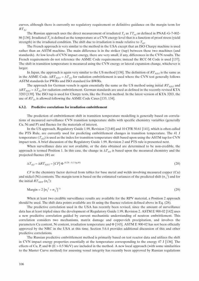
curves, although there is currently no regulatory requirement or definitive guidance on the margin term for RTTo.
The Russian approach uses the direct measurement of irradiated Tk as TTref as defined in PNAE-G-7-002-86 [136]. Irradiated Tk is defined as the temperature at a CVN energy level that is a function of proof stress (yield strength) in the irradiated condition. The shift due to irradiation is made relative to Tk0.
The French approach is very similar to the method in the USA except that an ISO Charpy machine is used rather than an ASTM machine. The main difference is in the striker (tup) between these two machines (and standards). At low levels of CVN impact energy, there are very small, if any, differences in the CVN results. The French requirements do not reference the ASME Code requirements; instead the RCC-M Code is used [137]. The shift in transition temperature is measured using the CVN energy or lateral expansion change, whichever is larger.
In Japan, the approach is again very similar to the US method [138]. The definition of RTNDT is the same as in the ASME Code. RTNDT = T41J for radiation embrittlement is used where the CVN test generally follows ASTM standards for PWRs and ISO standard for BWRs.
The approach for German vessels is again essentially the same as the US method using initial RTNDT and RTNDT = T41J for radiation embrittlement. German standards are used as defined in the recently revised KTA 3203 [139]. The ISO tup is used for Charpy tests, like the French method. In the latest version of KTA 3203, the use of RTTo is allowed following the ASME Code Cases [133, 134].
6.3.2. Predictive correlations for irradiation embrittlement
The prediction of embrittlement shift in transition temperature modelling is generally based on correla-tions of measured surveillance CVN transition temperature shifts with specific chemistry variables (generally Cu, Ni and P) and fluence for the materials of interest.
In the US approach, Regulatory Guide 1.99, Revision 2 [140] and 10 CFR 50.61 [141], which is often called the PTS Rule, are currently used for predicting embrittlement changes in transition temperature. The 41 J temperature (T41J) is used as the index for transition temperature shift based upon using the ASTM tup for CVN impact tests. A brief discussion of the Regulatory Guide 1.99, Revision 2 and PTS rule is presented next.
When surveillance data are not available, or the data obtained are determined to be non-credible, the approach is termed Position 1. In this case, the change in T41J is based upon the measured chemistry and the projected fluence () as:
T41J = RTNDT = [CF] (0.28 – 0.1 log ) (28)
CF is the chemistry factor derived from tables for base metal and welds involving measured copper (Cu) and nickel (Ni) contents. The margin term is based on the estimated variances of the predicted shift (
2) and for the initial RTNDT (I
2):
Margin = 2 [I2 +
2] ½ (29)
When at least two credible surveillance results are available for the RPV material, a Position 2 approach should be used. The shift data points available are fit using the fluence relation defined above in Eq. (28).
The predictive correlation used in the USA has recently been revised, since the amount of surveillance data has at least tripled since the development of Regulatory Guide 1.99, Revision 2. ASTM E 900-02 [142] uses a new predictive correlation guided by current mechanistic understanding of neutron embrittlement. This correlation considers two mechanisms, matrix damage and copper-rich precipitation, and involves the parameters Cu content, Ni content, irradiation temperature and [143]. ASTM E 900-02 has not been officially approved by the NRC in the USA at this time. Section 5.6.4 provides additional discussion of this and other predictive correlations.
The Russian predictive embrittlement method is primarily based on test reactor data and utilizes the shift in CVN impact energy properties essentially at the temperature corresponding to the energy 47 J [136]. The effects of Cu, P, and (E > 0.5 MeV) are included in the method. A new local approach (with some similarities to the Master Curve method) for assessing vessel integrity has recently been approved by Russian regulations
106

[144]. Additionally, a recent IAEA activity on embrittlement prediction for WWER-440 RPVs was completed and is discussed in Section 7.2.8.
In the French predictive models, one for design (RCC-M Code [137], Appendix ZG) and one for surveil-lance (RSEM Code [145], Article B7212), the effects of Cu, P and (E > 1 MeV) are included; Ni is also included in the surveillance predictive model. Both models use T41J temperature as the shift parameter. The design model has a margin built in the correlation, while the surveillance model is a mean predictive model.
The Japanese models in JEAC 4201-2000 [146] are mean predictions for CVN energy T41J transition temperature shift for both base metals and welds. For the base metals, Cu, Ni, P and (E > 1 MeV) are included, while the weld correlation includes the parameters Cu, Ni, Si and (E > 1 MeV).
In the latest German predictive method (KTA 3203 [139]), the predictive approach is based on a bounding graphical method to account for embrittlement. The effects of Cu, P and (E > 1 MeV) are included within a bound that does not directly predict shift in transition temperature, but gives a bounding shift in graphical form for a final RTNDT or Master Curve-based RTTo, called RTLimit. RTLimit is equal to 40C for all fluences less than 1 1019 n/cm2 (E > 1 MeV), and RTLimit increases linearly another 10C for each unit increase in fluence of 1 1019
n/cm2 above the 1 1019 n/cm2 threshold. This bound has been confirmed for all German RPV steels (both BWR and PWR) with Cu contents up to and including 0.15 wt% and Ni up to 1.1 wt%. There are some higher Ni welds (up to 1.7 wt%) that have been confirmed up to fluences of 6 1018 n/cm2, and the purpose of continued surveil-lance programmes is to check the validity of this upper bound for RTLimit.
6.3.3. Master Curve application utilizing existing surveillance programmes
With the alternative indexing parameter RTTo, surveillance capsule Charpy specimens can be used by fatigue pre-cracking the V-notch specimen or by reconstitution of broken V-notch specimen halves to directly measure irradiated RTTo. Other fracture mechanics specimens can also be used to determine To and RTTo if included in the surveillance programme. Changes have recently been made through ASTM Subcommittee E10.02 on behaviour and use of nuclear structural materials to add more emphasis for direct measurement of fracture toughness in ASTM E 185-02 (a revised standard method for design of a surveillance programme [147]) and ASTM E 2215-02 (a new standard method directed to the evaluation of surveillance capsule materials [148]). The use of RTTo is currently the only Master Curve approach directly applied in the USA, but lower tolerance bounds could be used from the actual master curve as an alternative, as done in Finland [149]. As mentioned earlier, the German standards also now allow use of RTTo.
6.3.4. Charpy V-notch upper shelf energy
Since the shift in CVN energy transition temperature is used as part of the indexing method for fracture toughness curves, limitations on the CVN impact energy must be acknowledged and included in structural integrity analyses. The use of 41 J as the shift criterion, assumes that the USE is high enough that it does not overly influence the shift. Current US regulations specify that the USE start no lower than 102 J and cannot drop below 68 J without performing special integrity analyses. Many countries follow the US approach or a slight modification for USE limitations. Note that a drop below about 68 J can also produce larger estimates of T41J
shifts.Correlative procedures have been developed to estimate the drop in USE, such as Regulatory Guide 1.99,
Revision 2 [140]. However, a drop in USE below 68 J does not necessarily mean that there is risk to the RPV for ductile fracture. Equivalent margins analyses have been performed to show that USE levels well below 68 J can show adequate fracture toughness resistance [150, 151]. The ASME Code, Section XI [20], Appendix K provides a fracture toughness J-R curve methodology and criteria that can be applied to assess USE drops.
6.4. PRESSURE–TEMPERATURE OPERATING LIMITS
Operating limit curves for normal plant operation are developed using approximately the same methodology in all countries. Key features that must be defined are:
107

— Assumed reference flaw size and shape;— Safety factors on pressure and thermal stresses;— Reference fracture toughness curve and safety factor to be used.
Table 27 illustrates the various definitions of these features as used in the different calculative approaches. The fracture mechanics approach in the USA is contained in the ASME Code Section III [132], Appendix G and Section XI [20], Appendix G. The rules for Japan are specified in JEAC 4206-2000 [146], Appendix 1. Note that the German methodology uses a combination of two methods, one of which is fracture toughness-based [152].
6.4.1. Assumed reference flaw
The reference flaw size and shape used for calculating P–T operating curves are generally quite large compared to current non-destructive inspection capabilities. In the methodologies employed in the USA, Japan, Germany (Method-2) and France (Method-1), the reference flaw is assumed to be ¼-thickness in depth with a length of 1.5 times the thickness. The Russian approach uses a reference flaw of ¼-thickness, but the length is ¾-thickness rather than 1.5-thickness. The French approach has a second method (Method-2) that uses a smaller, more realistic flaw size indicative of the size that could exist in a vessel. This smaller size is about one third that of the ¼-thickness flaw.
TABLE 27. PRESSURE–TEMPERATURE OPERATING CURVE DEVELOPMENT
SI method
Methodology Reference flaw Safety factor(s)Fracture toughness
curveComments
US ASME Code, Appendix G, Sections III and XI
¼-T depth, length of 1.5T
2 on p, 1 on t; 1 on fracture toughness
KIa curve (or KIC curve using Code Case N-641)
Russian PNAE-G-7-002-86 ¼-T depth, length of ¾-T
1 on p, 1 on t; 1 on fracture toughness
Specific KIC curve for normal operation
Safety factor on KIC included in curve itself
French RCC-M Code, Chapter B.3260:Two methods
Method-1: ¼-T depth, length of 1.5T;Method-2: 15 mm depth, length of 90 mm
Method-1: 2 on p, 1 on t; 1 on fracture toughness; Method-2: 1 on p, 1 on t; 2.5 on KIC and 1.43 on KIa for T–RTNDT < 50C; 1.43 on KIa and 1.43 on KJc for T–RTNDT > 50C
Method-1: KIa curve;Method-2: KIC and KIa curves
Different flaw sizes can be used, if justified, and evaluated using the same safety margins and fracture toughness curves
Japanese JEAC 4206-2000Appendix 1
¼-T depth, length of 1.5T
2 on p, 1 on t; 1 on fracture toughness
KIR curve, KIR curve for 2-pass bead is almost equivalent to ASME Code KIa
curve
New addenda to JEAC 4206 will allow use of KIC
German KTA 3201.2, Paragraph 7.9:Two methods; Method 1: Modified porse diagram
Method 2:¼-T depth, length of 1.5T
Method 2:2 on p, 1 on t; 1 on fracture toughness
Method 2:KIR curve, almost equivalent to ASME Code KIa curve
108

6.4.2. Safety factors on stresses
Most of the methodologies rely on a generic safety factor of two applied to pressure stress, with the safety factor on thermal stress set at unity. For leak and hydrostatic tests, the safety factor on pressure generally is reduced to 1.5. The Russian approach and the French Method-2 use a safety factor of unity for pressure stress, but the fracture toughness curve either has a safety factor included (Russian approach) or additional safety factors are applied to the fracture toughness curves (French Method-2).
6.4.3. Reference fracture toughness curve and safety factors
In the methods in which a safety factor of two is applied to the pressure stress, there is no additional safety factor applied to the reference fracture toughness curve. However, the reference fracture toughness curve used can vary. In the USA, the current ASME Code approach uses the KIa (KIR) curve, but an approved Code Case [153] allows use of the KIC curve instead of the more conservative KIR curve; a similar approach is being adopted in Japan. The French Method-1 and the German methods only allow use of the KIR curve. The Russian approach uses a specific KIC curve for normal operation that has a safety factor included in the curve since the safety factor on stress is unity. Method-2 of the French approach uses a combination of both the KIC and the KIa curves for the smaller assumed flaw size. Also, note that the French method allows for different flaw sizes from those defined if properly justified.
6.4.4. Attenuation of damage into the RPV wall
In order to calculate P–T curves, values of toughness are needed at the ¼-thickness and ¾-thickness locations in the RPV wall. Calculations are usually performed to determine the attenuation of neutron flux/fluence from the inside surface of the RPV into the wall. The best method for making these projections is to use dpa as the measure of fluence change [154], since dpa takes into account the change in neutron spectra that occurs as the neutrons are attenuated. Regulatory Guide 1.99, Revision 2 [140] uses this approach and specifies a generic exponential decay function. ASTM E 900-02 [142] recommends general use of a calculated dpa function with the exponential decay function as a backup position since it is generally conservative [154]. The dpa change through the RPV wall is then used to adjust the correlation parameter, , used in the predictive embrittlement correlations since dpa was not used in developing the embrittlement correlations identified in Table 26.
6.4.5. Low temperature overpressure protection
The US regulations require the use of a system to assure that inadvertent over-pressurization cannot occur during normal heat-up and cool-down such that the P–T limits are violated. This requirement can be met using different system approaches, the most common of which is to use a safety relief valve in the residual heat removal system. Some systems only have a single safety valve set-point, such that the operators must snake around an imposed knee based upon the limitations of the P–T curves and a lower limit from pump seal and/or cavitation restrictions. ASME Code Case N-641 [153] provides recent redefinition of calculation procedures for P–T curves and LTOP that are currently being implemented at operating plants.
6.4.6. Unanticipated transients
Unanticipated or non-normal operation transients sometimes occur that can exceed the P–T limits and generally require an integrity assessment to allow continued plant operation. The overall safety margin is known to be quite high due to conservative assumptions and applied safety factors within the generation methodology of P–T curves. In the ASME Code, Section XI [20], Appendix E, a procedure exists that allows a quick check on structural integrity; if that quick check is not adequate, a more detailed analysis can be performed, as specified. The purpose of Appendix E is to provide plant operators with a simple method to assess the severity of any unanticipated transient and to quickly document the severity so that plant operating time can be maximized.
109

6.5. PRESSURIZED THERMAL SHOCK
PTS is an event that was not included in the original design basis of the vessel. PTS involves a severe overcooling transient that also includes re-pressurization of the vessel, which only applies to PWRs. Table 28 lists the approaches that are used in the key structural integrity methods. Note that the US approach uses a probabi-listic fracture mechanics basis that was used to define generic screening criteria (related to the value of ART determined at the end of the operating licence life) that must be met or a plant-specific probabilistic risk assessment must be performed. There is an extensive PTS re-evaluation programme ongoing in the USA that may change the PTS screening criteria and the details concerning the probabilistic analysis.
Most of the other methods rely on deterministic analyses that are performed on a plant-specific basis using defined methodologies involving more complicated fracture mechanics evaluations than used for P–T curves. The definition of the applied stresses is complex, and requires thorough thermal hydraulics and mixing calcula-tions and models, which vary between the different PWR and WWER vessel designs. The Russian approach also allows use of probabilistic evaluation, as indicated in Table 28. IAEA Guidelines for PTS evaluation have been developed and are being used for WWER vessels [155].
TABLE 28. PRESSURIZED THERMAL SHOCK APPROACHES
SI method
Regulation Screening criteria Type of analysis Key details of analytical approach
US 10 CFR 50.61 Base metal and axial welds: <132C; girth welds: <149C
Probabilistic, if screening criterion is exceeded; use Reg. Guide 1.154
Pf < 5 10–6/reactor year;range of flaw sizes from distribution curve; cladding effects considered; crack arrest at ¾-T acceptable; benefit of warm pre-stressing allowed if no re-pressurization
Russian General rules of PNAE-G-7-002-86 and IAEA-EBP-WWER-08
None Primarily deterministic, but probabilistic can be used
Semi-elliptical surface flaws up to ¼-T depth with length = ¾-T; KIC initiation only with no safety factor on KIC; cladding effects considered; no benefit for warm pre-stressing; Pf < 1 10–7/reactor year, if used
French General rules of RCC-M, Appendix ZG
None Deterministic Combination of flaw sizes and safety factors depending upon transient categories; cladding effects considered; no benefit of warm pre-stressing; crack arrest allowed only for fourth category transients
Japanese JEAC 4206-2000Appendix 3
Simplified generic method of a comparison with KIC curve
Deterministic Size of semi-elliptic surface flaw approximately two times reliably detectable flaw depth with length six times the depth; cladding effects to thermal analysis considered; no benefit of warm pre-stressing
German No specific rule, but principles of KTA 3201.2 apply; sophisticated analyses employed
None Deterministic Size of semi-elliptic flaw two times reliably detectable flaw depth with length six times the depth; margins for emergency and faulted conditions are one on p and t; cladding effects included in practice; warm pre-stressing under discussion for inclusion; crack arrest can be applied to worst case transient
110

6.6. MITIGATION METHODS
In order to open the operating window for P–T curves and allow for a widened margin for PTS, mitigative measures may be applicable to reduce the impact of radiation embrittlement. These mitigative methods include:
— Use of an optimized fuel management scheme that reduces the neutron flux field at the RPV wall — this optimization can also reduce fuel costs when applied efficiently;
— Reconfiguration of the core using up to four times burnt fuel or shielding materials such as stainless steel or hafnium to reduce the flux at certain areas of the RPV wall;
— Raise the emergency core cooling system (ECCS) water temperature to reduce the thermal impact on the RPV wall during an overcooling event;
— Adjust the ECCS flow conditions to allow mixing that can also affect heat transfer, resulting in a reduction in the severity of the thermal stresses during an overcooling event;
— Thermal anneal the RPV beltline region to recover the fracture toughness of the material(s); — Improve the state of knowledge of the actual RPV materials by performing tests (such as fracture
toughness) on archive, sampled or surveillance specimens.
As indicated above, changes in the ECCS water temperature or different ECCS flow configurations can be categorized as those that reduce the severity of PTS transients. The frequency of the PTS transients also can be important when considering the potential risk of PTS using a probabilistic assessment. The neutron flux environment leading to embrittlement can also be changed to reduce the fluence accumulation at different locations in the RPV beltline using optimized fuel management strategies and core changes. In terms of improving the actual material properties, thermal annealing is the only method of transformation back to near the start of life conditions.
Thermal annealing has been a proven approach for Russian WWER vessels [156]. Use of measured fracture toughness on irradiated RPV materials (from either archive materials irradiated to match the RPV conditions, surveillance programme materials or sampled RPV materials) can provide more accurate knowledge of the actual RPV fracture toughness than use of current CVN-based approaches.
6.7. LICENSING CONSIDERATIONS
Tables 25 to 28 provide the general methodologies and regulatory licensing approaches used in the five key countries. The regulatory authority in other countries may use slight modifications to provide regulatory comfort relative to plant-specific considerations. Recent activities that are being implemented that may require country-specific consideration are:
— Extended and/or continued licence life (this is termed licence renewal in the USA and involves the extension or creation of a specific surveillance programme to meet an extended operating period);
— Increased power up-rates to provide additional output from existing plants (this process can cause potential changes to the neutron flux at the RPV wall and change the operating temperature of the RPV);
— Extended core operation up to two year fuel cycles, which can also change the time-weighted temperature of operation and the neutron flux exposure at the RPV wall;
— Unique fuel/core changes that can optimize the neutron flux field or meet other operational needs, such as use of mixed oxide (MOX) fuel.
Each of these actions will require regulatory approval in each country. Specific structural integrity assessments will need to be performed to satisfy the regulatory bodies. The general framework of these assessments will, most likely, follow the procedures and considerations described previously in this section.
111

7. IAEA AND INTERNATIONAL ORGANIZATION PROGRAMMES
7.1. INTRODUCTION
Major IAEA activities on technological, engineering and operational issues of nuclear power are mostly concentrated on studies of understanding mechanisms of degradation and their monitoring, management of maintenance options, economic aspects and human factors in approaches to nuclear power plant life management and oriented to the assistance to Member States to develop their capabilities for the informed decision making process during the implementation of plant life management (PLiM) programmes.
7.2. IAEA TWG-LMNPP
The TWG started in 1968 when the Working Group on engineering aspects of RPV irradiation embrit-tlement was established at the IAEA. However, after some time, it was decided that the scope of activities of that Group should not be narrowed to just the problem of irradiation embrittlement. In 1975, the Group recon-sidered the topics with which it would be involved. The Group was then renamed the “International Working Group on Reliability of Reactor Pressure Components” (IWG-RRPC). In the same year, the first terms of reference of the IWG-RRPC were introduced and 1975 became the official date for the establishment of the IWG. In 1990, the IWG-RRPC was renamed again to “International Working Group on Life Management of Nuclear Power Plants” (IWG-LMNPP) and operated up to this present year under this title. It was then decided to change the name of the group to Technical Working Group on Life Management of Nuclear Power Plants.
The purpose of the TWG-LMNPP is to provide the Secretariat of the IAEA with advice and recommenda-tions on the IAEA’s activities and forward programmes in this area by means of specialist meetings, training courses, CRPs, workshops, establishing, operating and maintaining databases etc., when they have particular relevance to reliable PLiM, and, specifically, on the priority, scope and content of publications in the form of guides and manuals, and meetings to be organized and sponsored by the IAEA.
Over the past 35 years, nine CRPs (sometimes scheduled as Phases) on RPV materials behaviour under neutron irradiation have been carried out by the IAEA within the scope of the TWG’s activities.
7.2.1. First project CRP-1
In 1971, the IAEA Working Group on Engineering Aspects of Irradiation Embrittlement of Reactor Pressure Vessel Steels elaborated and approved, as an initial step, a standard programme (Phase 1) of the CRP on “Irradiation Embrittlement of Reactor Pressure Vessel Steels” which should be performed on a reference steel ASTM A 533 Grade B Class 1 (HSST Plate 03) deriving from the Heavy Steel Section Technology (HSST) Program and provided to the IAEA by Union Carbide Corporation, USA (the operator of Oak Ridge National Laboratory (ORNL) at that time). Eight IAEA Member States (nine institutions) participated in that project: Czechoslovakia, Denmark, the Federal Republic of Germany, France, Japan, Sweden, the United Kingdom and the USA.
The main goals of the study were:
— To establish the basis for describing embrittlement, and confirm that performing the measurements of neutron spectrum, fluence and mechanical properties was sufficiently standardized to allow for a direct inter-comparison between national programmes without major adjustment of the data;
— To compare the embrittlement sensitivity of national steels with that of the standard steel- ASTM A 533-B-1 (HSST Plate 03).
112

As an outcome of CRP-1, no major discrepancies were observed in the results in spite of the use of unique irradiation assemblies in nine different reactors with individual evaluations of neutron fluence and neutron spectra. The same conclusion was made with regard to mechanical test procedures and data interpretation.
7.2.2. Second project CRP-2
In December 1976, the second Project (Phase II) with the title “Analysis of the Behaviour of Advanced Reactor Pressure Vessel Steels under Neutron Irradiation” was formally initiated. The number of participating Member States remained the same (eight countries — Czechoslovakia, Denmark, the Federal Republic of Germany, France, India, Japan, the United Kingdom and the USA with ten organizations).
The main goal of the project was to undertake a comparative study of the irradiation embrittlement behaviour of improved (advanced) steels produced in various countries. It was intended to demonstrate that careful specification of pressure vessel steel could eliminate or considerably reduce the problem of neutron irradiation embrittlement, and to show that knowledge had advanced to the point where steel manufacturing and welding technology could routinely produce steel RPVs of high radiation resistance.
The project lasted from 1977 to 1983, and the following main conclusions were obtained:
— Results from this programme showed that modern pressure vessel materials (plates, forgings and welds) possess high resistance to neutron irradiation damage;
— In general, and for those mechanical tests which show a response to neutron irradiation, the results demon-strated that reducing the copper content (together with low phosphorus content) of steels led to an improvement in their irradiation resistance;
— There was no systematic variation of Charpy USE change (decrease) with neutron fluence;— The results of fracture toughness tests showed that modern steels are more resistant to neutron irradiation
than the older pressure vessel steels;— Results from the Phase II programme underlined the shortcomings of the initial USNRC Regulatory
Guide 1.99 (Revision 1) approach, in particular with respect to high nickel contents and the description of upper shelf Charpy fracture energy decrease.
7.2.3. Third project CRP-3
This project was implemented during the period from 1983 to 1994. The popularity of the results achieved in the previous phases led to a further increase of participation bringing the number of participants up to 16 Member States.
The main objective of the third project was to consolidate the increasing body of knowledge on irradiation embrittlement and the techniques used to determine its significance. It was intended to establish guidelines for surveillance testing which could later on be used internationally.
For this study, 27 steels were offered by Japanese steel-makers. Japanese laboratory melts specially produced to assess composition effects and a ‘radiation sensitive’ correlation monitor material were of primary interest. This resulted in the procurement of a 25 t heat of such steel, produced as a special charge by the Kawasaki Steel Corporation in Japan, which was designated as JRQ [157].
The main conclusions from the study were as follows:
— Results from the programme showed that comparable knowledge, experience and irradiation and testing facilities in the Member States created well established worldwide comparable centres for evaluation of the behaviour of RPVs under neutron irradiation damage;
— Creation of a database of all experimental results obtained within this and previous projects was found to be a very useful instrument in analysis of all the data;
— Testing of ‘old’ and ‘advanced’ types of materials has revealed an effective way of decreasing the material susceptibility to radiation damage by decreasing phosphorus and copper contents;
— Specially manufactured material JRQ (with a higher content of copper and phosphorus) has been studied by all participants. Analysis of the obtained results supported a suggestion for using the JRQ steel as a ‘reference steel’ for future surveillance as well as research irradiation programmes;
113

— Mean trend lines have been determined for transition temperature shifts from impact testing as well as for yield strength increase tested at room temperature, all after irradiation at 290 and 270°C;
— Progress in neutron dosimetry resulted in better instrumentation and characterization of irradiation experiments even though common uncertainty in neutron fluence determination is still probably not better than 30%.
7.2.4. Fourth project CRP-4
In September 1996, a new IAEA CRP with the title “Assuring Structural Integrity of Reactor Pressure Vessels” was launched with 24 organizations from 19 Member States. The purpose of the project was to provide practical guidance in the field of monitoring RPV materials behaviour and to develop and assess a uniform procedure of testing small size (Charpy type) specimens applicable to surveillance programmes.
A large amount of experimental data has been collected within this programme. These data were intended to check the ASTM ‘Master Curve’ approach using the IAEA reference steel JRQ as well as other ‘national’ materials. The main aim of these tests was to verify the application of the Master Curve using small, pre-cracked Charpy size specimens suitable for RPV surveillance programmes. The main conclusions from this study were as follows:
— The Master Curve approach can be applied to a wide set of ‘national’ RPV-type materials for LWR and also for WWER-type reactors;
— The Master Curve approach is also applicable to dynamic fracture toughness testing — a strong difference between static and dynamic T0 temperature has been observed.
It was also demonstrated that the Master Curve approach is fully applicable for these materials, test specimens and material conditions using either the single or multiple temperature approach; practically no difference between results from both these approaches was found [158].
7.2.5. Fifth project CRP-5
Results from the IAEA CRP on “Assuring Structural Integrity of Reactor Pressure Vessels” supported the change from an impact transition temperature approach to a more exact fracture toughness methodology for individual RPV materials. However, the CRP identified some technical issues regarding testing and evaluation that require further study. The need to address those issues was implemented in the next IAEA CRP “Surveil-lance Programmes Results Application to RPV Integrity Assessment” which was started in 2000.
The existing (at the time) ASTM E 1921-97 standard for Master Curve evaluation considered only single temperature testing, while a multi-temperature testing approach may be more suitable for surveillance specimen programmes. Information on Master Curve slope can be examined and more test data utilized in determining the reference temperature T0.
Previous investigations confirmed that testing irradiated fracture toughness specimens and use of their data directly in RPV integrity assessment would increase evaluation reliability. These data could also be used to assess conservatism while comparing transition temperature shifts from Charpy impact tests and fracture toughness tests.
The project was implemented through two phases, A and B, experimental and analytical, respectively. Phase A results were documented in an IAEA publication [159] with the main conclusions as follows:
— The SINTAP analyses confirmed that the weak inhomogeneity of the 6JRQ plate can be taken into account by applying the SINTAP procedure for a conservative Master Curve estimate of T0;
— The overall mean T0 values show, in accordance with previous investigations, that a bias of around 12C exists between the T0 values of CT and SE(B) specimen types with the CT specimens giving higher values of T0;
— The analyses of both the JRQ and the national materials confirm that the procedures specified in ASTM E 1921-02 as well as the SINTAP procedure are generally valid and applicable for characterizing JRQ-type steels and even steels showing distributed inhomogeneity;
114

— As a general recommendation for further research, the Master Curve-based approach, primarily applicable in the standard form, should be expanded further to a more generic form which includes procedures for testing the quality of data and special tools for analysing abnormal cases.
Phase B results were documented in another IAEA publication [160], a Technical Reports Series publi-cation. This report presents guidelines for application of the fracture toughness reference temperature, T0, determined by the master curve method. The report provides a flow diagram that users can follow for implemen-tation of the Master Curve approach to operating RPVs. As stated in the conclusions of the TRS, “It is reasonable to expect that in the future the determination of plant operating limits will be based on Master Curve methods”.
The characteristics of the CRPs were re-evaluated by the IAEA at this stage and their role was revised to focus on investigations of the fundamental issues identified in the earlier CRPs. Thus, the subsequent CRPs represent detailed studies of particular phenomena.
7.2.6. Sixth project CRP-6
CRP-6 was focused on WWER-1000 and PWR RPV steels with high Ni contents. Recent studies had shown that one of the most typical RPV steels with evidence of increase in irradiation sensitivity due to the presence of a high nickel content was WWER-1000 RPV steel 15Kh2NMFA. However, only limited data on neutron embrittlement of WWER-1000 steels were found in the literature, with the following main conclusions:
— Transition temperature shifts for the weld metals are higher than for the base metals;— The neutron-induced embrittlement of welds with high nickel content (1.5–1.9%) is higher than that of
welds with lower nickel content (1.1–1.3%);— Current surveillance data are not fully representative for RPV integrity assessment due to differences in
irradiation conditions of the RPV and surveillance specimens;— No empirical equation which takes into account nickel content for prediction of transition temperature
shifts is available at this time for WWER-1000-type steels.
As a result of such observations, 11 institutes from eight different countries and the European Union participated in this CRP, with irradiation experiments of the CRP WWER-1000 RPV materials being conducted by six of the institutes. In addition to the irradiation and testing of those materials, irradiation experiments of various national steels were also conducted. Moreover, some institutes performed microstructural investigations of both the CRP materials and national steels. It has also been known that high levels of nickel can have a synergistic effect with copper and phosphorus, increasing the radiation sensitivity of RPV steels. Some Russian WWER-1000 RPV steels have higher levels of nickel than used in typical Western steels. The radiation sensitivity of two higher nickel WWER steels, one forging with 1.2% nickel and one weld with 1.7% nickel were evaluated through a small round robin exercise and collection of data. The main conclusions from this CRP are as follows:
— The analysed results clearly show significantly higher radiation sensitivity of high nickel weld metal (1.7 wt%) compared with lower nickel base metal (1.2 wt%);
— For a given high level of nickel in the steel and all other factors being equal, high manganese content leads to much greater irradiation-induced embrittlement than low manganese content for both WWER-1000 and PWR materials;
— Microstructural investigations have shown, for both WWER-1000 and PWR materials, that nickel associates with copper in the irradiation-induced copper-enriched precipitates, and that manganese (and possibly silicon) is similarly associated;
— Experimental results and microstructural investigations for steel with very high nickel (~3.5%) have indicated that, when there is very little manganese and low copper, the radiation sensitivity is very low even for such a high nickel steel.
The results from this CRP were documented in an IAEA TECDOC [94].
115
7.2.7. Seventh project CRP-7
Irradiation embrittlement in WWER RPV materials is mostly assessed using empirical formulas from the Russian Guide “Standards for Strength Calculations of Components and Piping of NPPs”. These formulas are based mostly on results from irradiation in experimental reactors. Thus, CRP-7, “Evaluation of Radiation Damage of WWER RPV Using the IAEA Database on RPV Materials”, was focused on WWER-440 steels and the need for improved predictive embrittlement correlations. In this study, a group of eight representatives from seven Member States developed new correlations for WWER-440 RPVs that provide better predictive capabil-ities based upon chemical content and neutron exposure.
The CRP was accomplished through the completion of four tasks: (i) collection of WWER-440 surveillance and other relevant data and input into the IAEA International Database on RPV Materials (IDRPVM), (ii) analysis of radiation embrittlement data of WWER-440 RPV materials using the IDRPVM database, (iii) evaluation of predictive formulas depending on material chemical composition, neutron flux and fluence, and (iv) guidelines for prediction of radiation embrittlement of operating RPVs of WWER-440 including a methodology for evaluation of surveillance data of a specific operating unit.
The new correlations were developed in a framework that better simulates the known embrittlement mechanisms for these steels, and was published in IAEA-TECDOC-1442 [161].
7.2.8. Eighth project CRP-8
CRP-8 is an ongoing extension of CRP-5 in that some of the outstanding issues associated with use of the Master Curve fracture toughness methodology are being studied in more detail. The overall objectives of CRP-8 include: (i) better quantification of fracture toughness issues relative to testing surveillance specimens for application to RPV integrity assessment and (ii) development of approaches for addressing MC technical issues in integrity evaluation of operating RPVs. Since the Master Curve approach is applicable to all nuclear power plant ferritic steel components, including the RPV, the scope of materials to be addressed will include both RPV and non-RPV materials. The three topic areas that are being investigated are: (i) test specimen bias, constraint and geometry; (ii) effect of loading rate; and (iii) changes in Master Curve shape. More detailed descriptions of the topic areas are available in Refs [162–164].
This CRP is currently in progress.
7.2.9. Ninth project CRP-9
The focus of CRP-9 is to develop a critical review and benchmarking of calculation methods for structural integrity assessment of RPVs during PTS events. Various deterministic benchmark calculations will be performed to identify the effects of individual parameters on RPV integrity, and to develop recommendations for best practices to be used in PTS evaluations.
As an overall objective, a series of deterministic benchmark vessel integrity calculations for a typical PTS regime will be conducted; such calculations will involve variations in specific critical parameters to quantify their effects on RPV integrity during PTS. This will be done for both WWER and PWR 3-loop RPVs, with one outcome to prepare an IAEA Technical Report. It is expected that this handbook will contribute to better technical support of nuclear power plant operation safety and life management. The deterministic calculations will have broader application even for probabilistic evaluations of RPV failure frequency through characteri-zation of the fracture mechanics sub-routine.
A second phase of the CRP will be the updating of a previous draft IAEA report on review of pressurized thermal shock. That draft report presents a broad international survey of the PTS issue, but was prepared several years ago and is now outdated. One substantial enhancement to the new report on PTS will result from incorpo-rating the recommended good practices and integrity criteria.
116

7.3. IAEA DATABASE ON RPV MATERIALS
On the basis of the experience from IAEA CRP “Optimising Reactor Pressure Vessel Surveillance Programmes and Their Analysis-CRP-3” and “Assuring Structural Integrity of Reactor Pressure Vessels-CRP-4”, it was concluded that all available experimental data be put into the IAEA database from the very beginning of the project. This database was elaborated by the Atomic Energy Research Institute (AEKI) in Budapest that also is a custodian of the database. This former database was extended for the purpose of other IAEA CRPs and was later modified for the purpose of the IAEA International Database of Reactor Pressure Vessel Surveillance Specimen Programmes (IDRPVM).
This database is divided into two parts: (i) research and (ii) surveillance. Both parts are governed by their own status with rules for data supply as well as data release. The research part is available for all participants of CRPs, while the surveillance part is only available for organizations/countries that supplied their own surveil-lance specimen test data.
7.4. EUROPEAN UNION INTERNATIONAL PROGRAMMES
At the European Union level, several programmes have been recently carried out and are running to date on PLiM issues including embrittlement. An overview of the projects carried out within the AMES (Ageing Materials European Strategy) European Network operated by the Joint Research Centre (JRC) is presented in the following sub-sections. Most of these projects are co-financed by the Nuclear Safety programme, EURATOM part of the Framework Programme, operated by DG RTD. Additionally, the JRC is supporting the TACIS/PHARE Programme in this field.
7.4.1. JRC programmes on PLiM; embrittlement as key issue
The AMES (Ageing Materials Evaluation and Studies) network was set up in 1993 to bring together the organizations in Europe having the greatest expertise in nuclear reactor materials assessment and research on ageing management [165] with the aim of studying ageing mechanisms and remedial procedures for structural materials used for nuclear reactor components.
The main objective of the network in the 5th Framework Programme is the ATHENA project, which is aimed at summarizing the obtained achievements and editing guidelines on important issues like the Master Curve, effect of chemical composition on embrittlement rate in RPV steels, re-embrittlement models validation after WWER-440 annealing and open issues in embrittlement of WWER-type reactors.
To fulfil the strategy developed by the AMES network, in line with the priorities of European industry, several key projects in the field of RPV irradiation embrittlement were executed during the 4th and are currently running in the 5th EURATOM Framework Programme. Their general purpose is to understand the influence of various embrittlement. An overview of AMES projects throughout the 4th Framework Programme is given in Refs [166, 167].
7.4.2. 4th and 5th EURATOM Framework Programme projects
Descriptions of the status of relevant ongoing projects carried out within the AMES network in the 5th Framework Programme are presented next [162].
7.4.2.1. ATHENA Concerted Action
ATHENA is a thematic network organized in task groups on specific strategic and technical issues to meet the objectives of the AMES Steering Committee as started in November 2001. The key elements of ATHENA are: Master Curve implementation for fracture toughness assessment; annealing and re-embrittlement issues; radiation embrittlement understanding; and thermal ageing understanding and potential and synergisms.
117

7.4.2.2. PISA
The PISA (Phosphorus Influence on Steel Ageing) project has the objective of improving the physical understanding of irradiation embrittlement due to segregation of phosphorus to grain boundaries and subse-quently reducing the fracture toughness of RPV materials due to an intergranular failure mechanism. The goal is to improve predictability through developing physical understanding of both the phosphorus segregation process and any resultant change in mechanical properties. Physical understanding will be enhanced through focussed experimental investigations of irradiated steels and model alloys coupled with associated modelling studies.
7.4.2.3. REDOS project
The scope of the REDOS project is the accurate determination and benchmarking of radiation field parameters relevant to RPV monitoring; this project follows from the FWP4 MADAM project. The neutron exposure of the RPV and reactor internals is a key factor that has to be reliably quantified for assessing component lifetime. Irradiation embrittlement is the most damaging mechanism in RPV lifetime evaluation. Despite improvements in calculation of neutron field parameters with the most current and corrected cross-section values, discrepancies can exist between calculated and measured values, especially in ex-vessel positions. To resolve these discrepancies, experimental and computational techniques have been combined.
7.4.2.4. COBRA
COBRA is a project that tackles the issue of uncertainty in measurement of the irradiation temperature at which WWER-440 reactor surveillance capsules are subjected [168]. Non-homogeneous neutron and gamma flux distributions create a temperature gradient along the capsule and possible overheating (as compared to the real temperature of the RPV). This overheating can produce non-conservative surveillance data. Traditionally, temperature melting monitors have been used, but they have shown uncertainties in assessing temperatures in the range of 272 to 292ºC. Hence, a special direct temperature measurement system using thermocouples has been implemented at the Kola nuclear power plant to verify actual surveillance capsule temperatures. A consortium that includes Russian, Armenian and European institutions has been established. Results have shown that the irradiation temperature of the surveillance specimens is about 272ºC and, therefore, meaningful for RPV applications.
7.4.2.5. FRAME
This FRAME project is concerned with fracture mechanics-based trend curves for PWR and WWER RPV materials. The scope is to validate use of the Master Curve approach, as compared to the usual increase of ductile-to-brittle transition temperature assessed by Charpy impact testing. Cleavage initiation fracture toughness is the property needed in structural safety analyses of the RPV. However, this property is not measured directly for the irradiated (nor for the annealed or re-irradiated) material condition. Instead, a correlative embrittlement estimation based on the Charpy V test is used, even though the Charpy V test can be, in many respects, a different material property than initiation fracture toughness. Hence, the current under-standing of embrittlement may be biased when only Charpy V tests are used.
7.4.2.6. GRETE
GRETE is a follow-up project of AMES-NDT, which was dedicated to ageing monitoring of non-irradiated materials. The main objectives of GRETE are to assess and monitor (using a round robin exercise on non-destructive techniques) degradation of RPV steels due to neutron irradiation and thermal fatigue in piping steels. The techniques studied include thermo-electric and magnetic effects. The results could be important for future RPV surveillance programmes, since a validated non-destructive measurement of surveillance specimens could provide an alternative to destructive testing.
118

7.4.2.7. TACIS/PHARE Programmes
Within the scope of TACIS (technical support to former Soviet Union countries) and PHARE (technical support to other WWER operating countries) programmes, several projects have been carried out and are planned for WWER-specific RPV integrity assessment, surveillance and embrittlement issues. During the 4th EURATOM Framework Programme, some projects proposed by the Steering Committee of the AMES network were performed using non-destructive monitoring techniques for thermal ageing, reference dosimetry, reconstitution techniques and fracture toughness measurements. The projects REFEREE, RESQUE, MADAM and AMES-NDT were carried out. MADAM and AMES-NDT were mentioned earlier.
7.4.2.8. RESQUE
RESQUE (Reconstitution Techniques Qualification & Evaluation to Study Ageing Phenomena of Nuclear Pressure Vessel Materials) is a project that has developed “Recommendations for Reconstitution of Non-Irradiated and Irradiated Charpy-size Specimens”. These recommendations were strongly needed by both operators and authorities to monitor the unavoidable continuous decrease of surveillance material availability. The provided guidelines and recommendations allow a potential user to qualify their reconstitution equipment and develop an acceptable reconstitution programme.
7.4.2.9. REFEREE
The REFEREE (Relation Between Different Measures of Exposure-Induced Shifts in Ductile–Brittle Transition Temperature) project undertook a comparison of methods for measuring irradiation-induced shifts in the ductile–brittle transition temperature on four different RPV materials covering a range of different reactor systems of interest within Europe. The results have been compared with existing data and predictive trend curves. Key results have focused mainly on the comparison between static and dynamic fracture toughness transition temperature shifts as well as between fracture toughness and Charpy V shifts. Demonstration of the continued integrity of RPVs requires that the transition temperature can be predicted as a function of irradiation exposure. Irradiation-induced changes are conventionally monitored by measuring the Charpy V shift in transition temperature using the reference temperature and toughness methodology; this methodology has generally proven to be very conservative.
7.5. RESEARCH PROGRAMMES IN THE USA
7.5.1. US Nuclear Regulatory Commission
The USNRC has sponsored research on irradiation effects on RPV steels primarily through the Heavy-Section Steel Irradiation (HSSI) Program at ONRL and the Radiation Embrittlement Damage Analysis and Predictions (REDAP) Program at UCSB. They were separately funded programmes, but included various mutually cooperative and coordinated activities. Moreover, both programmes included many international collaborations.
When the Heavy-Section Steel Technology (HSST) Program was initiated in 1967, irradiation effects were one of the designated major topics of investigation. In 1989, the HSST Program irradiation effects task was organized into a separate Heavy-Section Steel Irradiation (HSSI) Program. The HSSI Program incorporated experimental investigations focused on fracture toughness, microstructural investigations and theoretical model development. Major experimental projects have dealt with:
— Dynamic fracture;— Ductile tearing resistance of low USE welds (up to 203 mm thick compact specimens);— Fracture toughness of welds fabricated using current welding practice;
119

— Irradiation of a large number of small and large specimens (up to 203 mm thick compact specimens) of two welds to provide a basis for statistical analyses used to determine the temperature shift and shape of the post-irradiation KIc and KIa curves,
— Irradiation-induced degradation of stainless steel cladding;— Variability of Charpy impact toughness and fracture toughness of an irradiated commercial low upper shelf
weld;— Temper embrittlement susceptibility of irradiated and thermally annealed RPV weld HAZs;— Relationship of the Master Curve to a highly embrittled RPV weld and to a steel that fails by intergranular
fracture.
Advanced microstructural examinations such as APT, and physically based theoretical model development of controlling microstructural mechanisms were coordinated with experimental investigations to provide improved predictions of macroscopic embrittlement. It is anticipated that future USNRC-sponsored irradiation projects will concentrate on the need for fracture toughness data at high fluences, long times and for high embrit-tlement. Specific topics may include material variability; relevance of the fracture–toughness Master Curve to very high embrittlement levels; dynamic fracture; the intergranular fracture mode; further evaluation of specimen size effects, with special focus on the pre-cracked Charpy 3-point bend specimen; irradiation effects on high-Ni welds and on high-Cu low upper shelf welds at high fluence (potential effects of late blooming phases); effects of irradiation/annealing on propensity for temper embrittlement of weld HAZs; and continuing integration of irradiation experiments with modelling and micro-structural studies to improve predictive tools [169].
The REDAP Program at UCSB has been in existence for more than a decade, with a particular long time focus on single variable irradiation experiments. These experiments were designed to obtain high quality data on a large number of alloys to assess the effects of both individual and combinations of key variables — that is to develop an empirical embrittlement map. The experimental matrix includes literally thousands of alloy–irradiation condition combinations to assess the separate and interactive effects of flux, fluence and irradiation temperature, as well as metallurgical variables, such as composition, product form and heat treatment. The primary measure of embrittlement is changes in yield stress. Further, extensive microstructural characteriza-tions, using a combination of state of the art techniques, several developed in the UCSB programme, are being carried out on a significant fraction of the matrix. The experimental results are complemented and are being analysed by advanced multiscale modelling. Determining the conditions for the formation of so-called late blooming phases (e.g. Mn–Ni rich phases) is also a major focus of the programme [170]. In the area of microme-chanics, the UCSB programme completed a very large and comprehensive fracture toughness project to resolve the issue of specimen size effects due to both statistical variability and constraint associated with application of the Master Curve.
7.5.2. Research programmes funded by the Electric Power Research Institute
EPRI supports research on RPV integrity on several different fronts. Research activities related to integrity issues included in the ASME Boiler and Pressure Vessel Code and ASTM Standards are significant areas of EPRI support. Most recently, these activities have included:
— The advancement of the Master Curve fracture toughness methodology through development of ASME Code Cases (N-629 and N-631), ASTM Standards revisions (ASTM E 1921-02, ASTM E 185-02 and E 2215-02) and IAEA CRP participation;
— Revision to the surveillance-based embrittlement correlation (ASTM E 900-02) using mechanistic guidance and statistical evaluation of surveillance capsule test results; activities are continuing to assess new surveillance data as they become available and potential impact on the current embrittlement corre-lation(s);
— Summary state of the art review of the potential for phosphorus segregation leading to possible inter-granular fracture in RPV steels;
— Summary state of the art review of the assessment of through-wall attenuation of damage in RPVs; involvement in an IAEA programme on a simulated through-wall experiment is currently underway;
120

— Coordination with the USNRC on the re-evaluation of the current PTS screening criteria;— Development of an integrated surveillance programme for all US BWR vessels.
EPRI has coordinated programmes with several different international organizations, such as EdF in France and CRIEPI in Japan. The Joint Research Program with CRIEPI has been a very successful long term programme (for over ten years) that has focused on microstructural assessment and mechanistic understanding of radiation embrittlement.
8. CURRENT STATUS AND MAJOR TECHNICAL ISSUES REGARDING IRRADIATION EMBRITTLEMENT
8.1. INTRODUCTION
The safety of commercial LWRs is highly dependent on the structural integrity of the RPV. The degrading effects of neutron irradiation on carbon and low-alloy pressure vessel steels have been recognized and investi-gated since the early 1950s. In those steels at RPV operating temperatures (~288C), radiation damage is produced when neutrons of sufficient energy displace atoms from their lattice sites. The defects formed in the steel as a result of those displacements typically cause hardening and a decrease in toughness. The decrease in toughness is most commonly represented by an increase in the ductile–brittle transition temperature and a decrease of the USE as measured by the CVN impact test. The synergistic effects of neutron fluence, flux and spectrum, the irradiation temperature, and the chemical composition and microstructure of the steel must be understood to reduce the uncertainties associated with the development of predictive models of embrittlement. The CVN toughness, however, is a qualitative measure that must be correlated with the fracture toughness and crack-arrest toughness properties, KIc and KIa, necessary for structural integrity evaluations. Where practicable, direct measurements of the fracture toughness properties are desirable to reduce the uncertainties associated with correlations. The integration of irradiation experiments with modelling and microstructural studies has resulted in considerable progress in understanding radiation-induced embrittlement of RPV steels.
This section provides a brief summary of major technical issues regarding embrittlement of commercial nuclear RPVs. The motivation for this summary is to identify key issues that require further research to provide information not currently available or to enhance existing information with a view towards reducing associated uncertainties.
8.1.1. Radiation damage mechanisms
The last decade has seen remarkable progress in developing a mechanistic understanding of irradiation embrittlement of RPV steels. This understanding has been exploited in formulating robust, physically based and statistically calibrated models of CVN-indexed transition-temperature shifts. These semi-empirical models account for key embrittlement variables and variable interactions, including the effects of material chemistry (copper (Cu), nickel (Ni) and phosphorus (P)) and environment (fluence (t), flux () and irradiation temperature (Ti)). Models of evolution of nanoscale precipitates rich in copper, manganese and nickel are quantitatively consistent with experimental observations of the complex interplay between these elements and other embrittlement variables. The models also explain other effects, such as those associated with post-weld heat treatment and many aspects of the interactive flux–composition–temperature dependence of embrit-tlement. Models have been extended to treat post-irradiation annealing and re-embrittlement based on tracking the fate of key alloy constituents and defects.
The physical basis underlying the models is the evolution of several populations of nano-scale features in RPV steels during irradiation. This evolution and the nature of the features are linked to the key embrittlement variables and how they mediate embrittlement through the micromechanics of the transition temperature shift,
121

TT. These features can be grouped into three classes. The dominant features in highly embrittled steels are copper-rich precipitates or copper-catalyzed, manganese–nickel-rich precipitates (MNPs). Additionally, two types of matrix features evolve: those that are thermally unstable (UMFs) and those that are stable at typical RPV operating temperatures (SMFs). These features evolve primarily as a consequence of radiation-enhanced diffusion and defect clustering, and their evolution can be modelled in terms of these processes. These features lead to increases in the yield stress, y, by serving as obstacles to dislocation motion, and this hardening mediates the transition temperature shift. This relationship between microstructure, y, and TT can be modelled by a combination of the micromechanics of dislocation-barrier interaction, computer simulation, and analysis of data trends. The resulting models can be calibrated by data obtained from fundamental systematic studies, generally obtained with the use of research reactors, as well as power reactor surveillance data. In the latter case, the physical models are used to guide the formulation of mathematical constructs to correlate and statistically fit the large database.
The success of the resulting models in correlating databases with a fairly wide range of metallurgical and irradiation variables demonstrates that the separate and combined effects of Cu, Ni, P, Mn, t, , Ti, post-weld heat treatment, and annealing times and temperatures are reasonably understood. These models have provided early warnings of potential technical surprises, such as the contribution of MNPs in high-nickel steels to embrit-tlement by late blooming phases, and they have enabled the assessment of outliers in the database as well as other contradictory observations. However, these models and our present understanding of radiation damage are not fully quantitative, and do not treat all potentially significant variables and issues.
8.1.2. Fracture toughness
Over the past three decades, developments in elastic-plastic fracture mechanics have been largely driven by the need for accurate prediction of irradiated RPV models. A number of consensus standards and codes have been developed for determining KIc, JIc, J-R curves, KJc, and KIa of RPV steels. These standards have led to a consistent determination of those properties that in turn have resulted in the development of databases that are useful for statistical analysis and establishment of uncertainties. Major irradiation projects have been completed, providing critical information regarding the fracture behaviour of RPV steels under conditions of irradiation, thermal annealing and re-irradiation, to include the effects of copper, nickel and phosphorus contents, the relationships between Charpy-impact toughness and fracture toughness/crack-arrest toughness, temperature shift and shape of the KIc and KIa curves, stainless steel cladding and low upper-shelf welds. Moreover, fracture toughness data have been obtained in sufficient quantity to permit probabilistic application. Relative to PTS analysis, the results are directly applicable as the calculations of failure probability are dependent on the initiation and arrest toughness of the materials. These fracture toughness data have been obtained with both very large and relatively small test specimens, allowing for increased understanding of specimen-size effects. Techniques have now been developed that permit determination of fracture toughness transition temperature using a few relatively small specimens as in the revolutionary advance of the Master Curve concept. Moreover, the combination of irradiation experiments with modelling and microstructural studies provides an essential element in ageing evaluations of RPVs.
8.2. SIGNIFICANT TECHNICAL ISSUES
A number of sources representing the views of various researchers from the international community were reviewed to determine their recommendations for critical research in irradiation effects in RPV steels. Although this brief survey is not comprehensive, Refs [171–178] were used to summarize those recommendations.
8.2.1. Material variability and surrogate materials
The subject of material variability has experienced increasing attention in recent years as additional research programmes began to focus on the development of statistically viable databases. This attention is true not only for CVN toughness but also for fracture toughness when it became clear that considerable scatter in cleavage fracture toughness occurs in the ductile–brittle transition temperature region of RPV steels. With the
122

development of the Master Curve approach for fracture toughness and the potential use of elastic-plastic fracture toughness data for direct application to the RPV, attention has focused on the issue of surrogate materials. The issue of surrogate materials is one of representation, i.e. to what extent can a given material represent a different material contained in the RPV. This issue is not new, in that many surveillance programmes contain CVN specimens of a different heat of base metal or different weld than that in the RPV. The potentially large margins associated with differences between surveillance steel surrogates and the corresponding uncer-tainties regarding the actual vessel materials are overriding issues. Addressing this issue requires models that include the effects of all pertinent variables and assessment of potential distributions of these variables. Applica-tions for use of the Master Curve approach have been made to the USNRC, and the PTS re-evaluation effort is underway; the development and acceptance of appropriate uncertainties are required for these activities.
8.2.2. High fluence, long irradiation time and flux effects
The combined issue of high fluence, long irradiation time and flux effects is directly related to many of the other issues, particularly the predictive embrittlement models. With the large number of commercial nuclear plants in the USA and other countries expected to request life extension, this topic is an area requiring additional critical research.
— Modelsand increasing experimental evidence suggest that phases rich in Ni and Mn may form in low Cu steels. Results of thermodynamic calculations show Mn–Ni rich precipitates are promoted by increasing Ni and Mn content and lower irradiation temperatures. Because these phases may require a small degree of Cu precipitation to catalyze their nucleation, they may not contribute to hardening and embrittlement until relatively high fluences. The delayed embrittlement caused by these late blooming phases could produce an effect that could have serious implications to RPV life extension. It is important to understand and quantify the composition–flux–fluence–Ti regime in which they evolve, and develop a better quanti-tative description of their contribution to embrittlement;
— Unexpected damage rate effects at intermediate flux, coupled with evidence of low flux and/or long time enhancement of embrittlement, are very important unresolved issues related to embrittlement correlation models. The potential for LBP emerging in some composition–fluence–temperature–flux regimes could result in severe underestimates of shifts based on current models by up to 50°C or more, if future long irradiation time data validate such an effect.
8.2.3. Master Curve fracture toughness
The Master Curve was identified by almost every source as a recommended subject for continued research. The issues most identified were the shape of the Master Curve at high levels of embrittlement and at high fluence, specimen size, dynamic loading (including crack-arrest), the effects of intergranular fracture and the technical underpinning for the universal shape of the curve.
— How the Master Curve fracture toughness data relate to CVN data relative to shift correlations and how the database(s) should be maintained need to be addressed. Since the Master Curve method allows direct measures of KJc from surveillance specimens, the issue of surrogate materials arises, i.e. the degree to which available materials represent the actual vessel (see Section 8.2.1). Further, a basic understanding of similar-ities and differences in the fracture response and the TT measured in Charpy versus KJc tests is needed to allow integration of the enormous surveillance database with new Master Curve results;
— The effect of irradiation on the shape of the Master Curve in sensitive steels and enhanced constraint loss following irradiation due to reductions in strain hardening must be addressed in application of the MC method to specimens from the surveillance programmes. These issues are particularly important for sensitive high-nickel steels. The USNRC is currently sponsoring two projects related to the shape of the Master Curve, one in the Heavy Section Steel Irradiation (HSSI) Program at ONRL and one at UCSB. The HSSI project will provide data at a very high level of embrittlement (TT of 175C) with one submerged-arc weld. It has been recommended that a second irradiation be conducted with a base metal or at least with one other weld if a base metal is not available with sufficient radiation sensitivity. The UCSB
123

project will provide a substantial amount of data related to constraint and specimen size effects, as well as development of a micromechanics basis that underpins the universal shape of the Master Curve. This issue takes on additional relevance if the PTS screening criteria are increased as a consequence of the ongoing PTS re-evaluation. This effect is also studied within the European Commissions’s 5th Framework Programme project VOCALIST where irradiation damage is simulated by special heat treatment of the steel;
— The issue of specimen size is directly applicable to surveillance specimens, even to those previously tested and which might be reconstituted. Questions regarding constraint limits for the Master Curve method and the pre-cracked Charpy (PCVN) specimen need to be resolved. Use of even smaller specimens machined from broken surveillance specimens highlight the significance of this issue;
— Very little research has been conducted on the relevance of the Master Curve to fracture toughness data from specimens that fail by intergranular fracture. The USNRC has sponsored one project through the HSSI Program that has demonstrated that failure of an RPV steel by 100% intergranular fracture will not be adequately characterized by the Master Curve because brittle fractures were observed at test tempera-tures well above the tolerance bounds associated with the Master Curve. However, observations in cases with up to about 20% intergranular fracture on the fracture surface do not appear to show this anomaly. This issue is relevant to RPV steels that have been irradiated and then thermally annealed, primarily because no observations of significant intergranular fracture of RPV base metals and weld metals have been reported in the irradiated condition. The portions of the RPV considered most susceptible are the coarse-grain regions of the weld HAZ and in those base metals with relatively high phosphorus content.
8.2.4. Attenuation
The current attenuation equation in Regulatory Guide 1.99, Revision 2 is based on very sparse data. There is still some controversy over the way in which embrittlement variations through the RPV wall arising from attenuation of the neutron flux should be estimated. There is no overall consensus on the appropriate exposure unit, whether it should be fluence greater than 1 MeV or dpa; although a recent review funded by EPRI [154] has concluded that dpa is the most appropriate unit for consideration of through-wall effects. Reference [160] also provides a discussion of this issue. The independent and combined effects of the following factors, all of which may vary within the vessel wall, need to be considered: (i) neutron flux spectrum, (ii) pertinent damage dose unit (or units), (iii) dose rate and temperature, and (iv) starting properties, chemistry and microstructure. Assessments of attenuation implicitly depend on all these factors and how they are (or are not) treated in analyses based on trend curve equations. Most often, several of these other factors influence attenuation more than the choice of a particular dose unit (e.g. dpa versus E > 1 MeV), which is the issue of most debate.
There are several types of research that are needed to better resolve both the issue of the proper dose unit and to provide a proper framework for assessing attenuation. For RPV integrity analyses, such as in the PTS scenario, in which a flaw initiates and propagates deeper into the wall, the attenuation of embrittlement is of importance for determining crack-arrest toughness and re-initiation fracture toughness. Development of the attenuation model can be accomplished through test reactor experiments or through direct examination of a decommissioned RPV. Examination of material from decommissioned RPVs would provide valuable data for through-thickness attenuation of radiation damage and for validation of surveillance data and predictive embrit-tlement models. The effects of attenuation depend strongly on metallurgical variables such as Cu and Ni, and irradiation variables such as fluence and neutron spectrum. In this case, attention must be taken of the fact that material properties may vary substantially through the vessel wall and their initial values are not always well known. Of course, through-wall variations in chemical composition, microstructure and the unirradiated fracture toughness would also confound elucidation of the attenuation in a given RPV. A test reactor experiment could be conceived and conducted given an appropriate facility, with appropriate attention given to the issue of flux effects. One such experiment is underway through an IAEA Technical Cooperation project. As with many other issues, this issue increases in importance at higher fluences and with life extension. Since sampling studies are limited in their direct general implications, it is absolutely essential that they be conducted within the context of the overall knowledge base and used as a test case to develop improved and integrated methods.
124
8.2.5. High-nickel welds
It is well known that increasing nickel content, all other factors being equal, causes increasing embrit-tlement in RPV steels. This issue may have significance because there are US RPVs with weld metal nickel contents as high as 1.3 wt%. However, there is a paucity of data available for Western steels with nickel contents in excess of 1.0%, the limit of Regulatory Guide 1.99, Revision 2. Accumulating data from Russian WWER steels show embrittlement increasing exponentially with nickel content above about 1.3%, and some welds in WWER-1000 RPVs contain nickel as high as 1.9 wt%. Moreover, as discussed in Sections 4 and 7, the effects of nickel are greater with higher levels of manganese. Since the WWER steels are basically Ni–Cr–Mo steels, it is not obvious that such a level is appropriate for US steels, which are Mn–Mo–Ni steels. Moreover, the subject of high-nickel content is applicable to concerns of late blooming phases at high fluences, potential effects on the development of CRPs and effects on post-weld heat treatments.
The interactive effects of high nickel, manganese and phosphorus need to be carefully examined. The strong synergistic interactions between copper, nickel and manganese generally are understood at low to inter-mediate fluence; recent results on very high nickel steels (approximately 3.5 wt%) with very low manganese have shown very little embrittlement even at high fluences (see Section 7.2.6). However, modelling at higher fluences, in both low and higher copper steels, needs to be established. Potential interactions with copper and phosphorus effects at high fluence have not been quantified.
8.2.6. Modelling and microstructural analysis
Modelling and microstructural analysis are identified separately, because they represent the core of research in irradiation effects. Prediction of irradiation-induced embrittlement for any given RPV steel is the goal. Key examples are:
— Matrix damage: The form of matrix damage in RPV steels is an issue because the nature of the defects (features) has not been resolved. In spite of the tremendous advances in, for example, electron microscopy, APFIM, SANS and positron annihilation, no technique has been able to resolve the form of the defects. For low-copper steels, where the matrix defects are normally the only embrittling features, there is very large scatter in the data. This large scatter is a reflection of our limited understanding of the nature of the matrix defects and the metallurgical and environmental variables that mediate their evolution and contri-bution to hardening and embrittlement. As a consequence of the large scatter, predicted embrittlement at high fluence may be non-conservative. This is particularly significant for high-Cu steels, where a large, matrix-defect contribution adds to the CRP term. Evaluation of the surveillance database suggests that above a fluence of 1023 n/m2, predictions from ASTM E 900-02 or USNRC models may not be conservative with respect to matrix damage. Hence, resolving the nature of these defects and the key embrittlement variables that dictate their evolution is imperative;
— Database for advanced modelling: Recent years have also witnessed rapid advances in computational capabilities for realistic simulation of complex physical phenomena such as irradiation embrittlement. Through very close integration with experiment, and incorporating advances in the underlying scientific understanding in pertinent areas of materials science and mechanics, the potential of realistic simulations of the long term in-service performance of reactor components has become a reality. As pointed out in Section 4, an ambitious modelling programme, known as the REVE project, has been initiated in Europe. REVE is a coordinated international programme (USA, Japan and Europe) to develop tools for numerical simulation of irradiation effects and ageing in LWR reactor components in the form of a virtual test reactor (VTR). A comprehensive simulation of the RPV has been chosen as the Phase I target of REVE. This application has been chosen because of its importance, the extensive existing knowledge base on pertinent damage mechanisms and the previous success in modelling many aspects of embrittlement. This REVE project will continue as a 6th Framework Programme project VOCALIST.
Even without specific research to identify and understand radiation-damage mechanisms, studies are needed to develop the models necessary for prediction of embrittlement in the various material components of the RPV. As stated earlier, the combination of irradiation experiments with modelling and microstructural
125

studies has provided an essential element in ageing evaluations of RPVs, and continuing integration of irradiation experiments with modelling and microstructural studies is an essential element in the evolution of improved predictive tools. The conduct of experiments and collection of data without modelling leads to an inefficient programme. Research is needed not only to develop predictive models but also to guide future exper-iments. Tremendous advances have been made in techniques, such as the AP, to query the microstructure with higher and higher resolution. The result is a significant gain in our understanding of many of the mechanisms of embrittlement. Continued advances in these tools can be expected as can the rewards likely to accrue from their use.
8.2.7. Pre-cracked Charpy and smaller specimens
The precracked Charpy V-notch (PCVN) specimen and smaller specimens are identified as a separate issue due to the important link to RPV surveillance programmes. As stated earlier, this issue is also relevant to the use of previously tested CVN surveillance specimens that might be reconstituted, fatigue pre-cracked and tested for fracture toughness with the Master Curve approach. Questions regarding constraint limits for the Master Curve method and the PCVN specimen must be resolved. Use of even smaller specimens machined from broken surveillance specimens highlight the significance of this issue. Further evaluation of specimen size effects are needed to fully understand the limits of applicability and associated uncertainties. The IAEA has recently completed a CRP that has provided valuable fracture toughness data from PCVN tests conducted by many different laboratories (see Section 7.2.5). A follow-on project is underway to continue the evaluation of the specimen and to develop guidelines for application of PCVN fracture toughness to RPV structural-integrity evaluations (see Section 7.2.8).
8.2.8. Phosphorus segregation and potential intergranular fracture
The issue of phosphorus segregation leading to the potential for intergranular fracture is considered to be relevant to RPV steels that have been irradiated and then thermally annealed, primarily because no observa-tions of significant intergranular fracture (IGF) of RPV base metals and weld metals have been reported in the irradiated condition. The portions of the RPV considered most susceptible are the coarse-grain regions of weld HAZ and in those base metals with relatively high phosphorus content. A project, currently sponsored by USNRC research through the HSSI Program, has demonstrated that commercial RPV steels are susceptible to temper embrittlement through thermal ageing treatments. One of the commercial steels, heat-treated to represent the coarse-grain HAZ, also showed predominant intergranular fracture following post-irradiation thermal annealing under anticipated RPV annealing conditions. These results are inconclusive, however, because of the atypical post-weld heat treatment relative to an actual RPV. Even so, it was surprising that the material exhibited such substantial IGF since it contained only 0.007 wt% phosphorus. A repetition of the experiment with the same material given a prototypic post-weld heat treatment is underway in the HSSI Program at ORNL.
8.2.9. Annealing and re-irradiation
Post-irradiation annealing is an approach to mitigating embrittlement that has international interest and was widely used for WWER-440/V-230-type RPVs: 15 annealings were performed and seven reactors are still in operation. This mitigative approach has been identified by a number of sources as one associated primarily, but not exclusively, with life extension of nuclear power plants. The USNRC has issued a regulatory guide on thermal annealing of RPVs, but the US nuclear industry has not tested the procedure due to non-technical reasons. There are some annealing data for US RPV steels, but a paucity of re-irradiation data. However, the time–temperature response and the dependence of that response to metallurgical and irradiation variability has only been scarcely mapped, and the microstructural processes involved in damage recovery are not well understood. Moreover, the effects of the annealed microstructure on the re-irradiation response and the effects of metallurgical and irradiation variables on the re-embrittlement of pressure vessel steels has only had a cursory examination to date. Understanding the underlying physical mechanisms involved in post-irradiation annealing and re-irradiation embrittlement will be the key to optimizing the post-irradiation annealing conditions to
126

maximize both recovery and resistance to re-embrittlement. The available data suggest that the lateral-shift method for predicting re-embrittlement is applicable, but substantially more data from different steels are needed if thermal annealing is considered a viable option for commercial PWR-type RPVs. Since the time required to complete the necessary experiments is considerable, research must be initiated soon if data are to be available within five to ten years to meet the need for irradiated, annealed and re-irradiated results applicable to life extension conditions.
8.2.10. Database development
The surveillance database provides the basis for developing embrittlement correlations such as those in Regulatory Guide 1.99, Revision 2 and ASTM E 900-02. Additionally, these data are needed for validation of microstructure-based embrittlement models. It is essential that a complete and validated database be maintained and updated as additional surveillance data become available. Development of the IAEA Database of RPV Surveillance Data is well underway and could be a very useful tool for determination of the effect of individual material and environmental parameters as well as for more general predictive formulas.
8.2.11. Product forms and effective copper content
There appear to be significant differences in predictions between product forms (welds, plates and forgings) using the current US and other (e.g. French and Japanese) correlations; these differences are not well understood. In addtion, these differences include the effective copper content for the various forms, including weld metals fabricated with different welding fluxes. Such differences may be the result of non-physical factors and/or untreated variables, such as the manganese content or microstructural differences. Further, through-wall gradients and other effects of heat treatment and fabrication details may be significant and particularly beneficial for shallow cracks. Locally inhomogeneous microstructures and chemistries, such as ghostlines, banding, HAZs and general fine-scale-brittle zones, present difficult issues and require estimates of their macroscopic significance.
8.2.12. Advanced materials
This topic is presented in the context of anticipatory research. The next generation of commercial power reactors may take advantage of higher strength steels with good fracture toughness, such as A543 Class 1 plate and A508 Grade 4 forgings (low-alloy steels with about 3% nickel). Other high-strength, low-alloy (HSLA) steels will also likely be considered. The higher strength will, of course, reduce the required thickness of the RPV, and those steels generally have excellent fracture toughness in the unirradiated condition. However, the lack of sufficient information regarding radiation sensitivity of those steels could result in unforeseen issues after construction for the next generation reactors.
8.2.13. NDE characterization of irradiated steels
A number of researchers have identified NDE characterization as a desirable tool to evaluate the embrit-tlement status of RPVs. There is a considerable body of research available on the subject of NDE characteri-zation of materials in other engineering fields, with conferences and symposia frequently held to discuss the latest findings. The USNRC, in fact, sponsored a limited amount of research in the 1990s. The USNRC also convened a special review panel of experts in 1999 that concluded that the sponsoring of a major research programme for RPV embrittlement was premature because the state of the art was not sufficiently advanced to warrant such a programme.
Uncertainties in the starting properties and metallurgical factors that influence embrittlement in actual vessel materials are both extremely important and challenging. Integration of techniques using small biopsies from actual vessels and non-destructive tests on the vessel itself may be possible. The key to this approach is that various sources of information, many based on state of the art techniques, be integrated within an overall knowledge framework. Recent developments in the use of combinations of Seebeck coefficient (or thermoe-lectric power) and electrical resistivity as a solute distribution spectrometer appear to be very important
127

elements to this approach. In combination with other methods such as hardness, these techniques may offer a physically viable approach to non-destructive or quasi non-destructive, field assessment of vessel embrittlement. This integrated approach could also be very useful in validation studies of retired vessels. Two similar projects have been carried out in Europe, AMES-NDT, within the 4th Framework Programme and GRETE within the 5th Framework Programme, where application of different methods has been tested.
8.3. CONCLUDING REMARKS
Research on irradiation embrittlement of RPV steels has been the subject of significant international research. The last decade has seen remarkable progress in developing a mechanistic understanding of irradiation embrittlement. This understanding has been exploited in formulating robust, physically-guided and statistically-calibrated models of CVN-indexed transition-temperature shifts. Over the past three decades, developments in fracture mechanics have led to a number of consensus standards and codes for determining needed fracture toughness parameters and associated uncertainties as derived from the embrittlement databases. Major irradiation projects have been completed, providing critical information regarding the fracture modelling of RPV steels under conditions of irradiation, thermal annealing and re-irradiation.
Even with this technical progress, there are still significant technical issues that need to be addressed to reduce the uncertainties in regulatory application. The key issues detailed in this section are those identified by a cross-section of researchers in the international community. Of the many significant issues discussed, those deemed to have the most impact on the current regulatory process are: (i) material variability and surrogate materials, (ii) high fluence, long irradiation times and flux effects, (iii) Master Curve fracture toughness and viability of the PCVN specimen, (iv) attenuation, (v) high-nickel welds and (6) modelling and microstructural analysis. Material variability and surrogate materials are the most overarching issues. Better understanding of the other issues is required in order to reduce the uncertainties associated with material variability.
9. CONCLUSIONS
Since neutron irradiation embrittlement of RPV steels is a key issue in the long term assessment of structural integrity for life attainment and extension programmes, this report has focused on technical advice to organizations preparing for life management or life extension of nuclear power plants. The mechanistic under-standing and application of measured mechanical property changes, RPV integrity requirements and assessment methods, and embrittlement management methods have been discussed. Light water RPVs, including detailed information on WWER reactor types, were covered.
The various types of RPVs have been described and compared, including information on RPV ferritic materials, consumables and fabrication. The non-irradiated baseline mechanical properties of the ferritic steels (plates, forgings and welds) were discussed along with NDE and hydrotest requirements.
Next, the effects of irradiation conditions on changes in mechanical properties of RPV steels were presented. A review of relevant mechanical and physical properties, various modes of fracture and the effects of irradiation on mechanical properties were presented. The effects of various irradiation conditions such as temperature, flux, fluence, neutron energy spectrum, thermal annealing and re-irradiation were also discussed.
The current view on the mechanisms of irradiation damage in RPV ferritic steels was summarized since a fundamental understanding of the embrittlement process can lead to more reliable projections of embrittlement as applied to structural integrity. The description ranged from primary damage production, measured micro-structure changes and development of predictive models. Environmental effects such as temperature, neutron energy spectrum and accumulated fluence were discussed.
Current worldwide assessment methods based on measured mechanical properties of RPV steels from operating nuclear plants have been documented. The data include results from Material Test Reactor (MTR),
128

commercial power reactor surveillance, and various research programmes. These programmes also include testing of ‘boat’ samples and detailed neutron dosimetry.
The principal procedures used throughout the world for assuring RPV integrity are documented as primarily related to operating pressure–temperature curves and PTS concerns for PWRs. Methods for mitigating undue degradation were described. Included in the discussion of the various methodologies were the regulatory rules and requirements for PSR and re-licensing.
IAEA and other international programmes were also summarized as related to irradiated material changes and RPV integrity. Included were IAEA CRPs and other activities involving international partici-pation.
The current state of the art in irradiation embrittlement, including current unresolved technical issues and research needs, was delineated. The use of potential new innovative techniques and methodologies was discussed.
This report addressed the effects of neutron irradiation of the ferritic steels and welds used in the construction of nuclear RPVs (light water PWR, BWR and WWER). Since the RPV generally is the key component in terms of safety and extended plant life, and is considered irreplaceable, structural integrity must be demonstrated without compromise. Utility engineers, designers, nuclear steam system suppliers, licensing authorities and researchers involved in nuclear plant life management and licence renewal should benefit from this report.
129

REFERENCES
[1] INTERNATIONAL ATOMIC ENERGY AGENCY, Assessment and Management of Ageing of Major Nuclear Power Plant Components Important to Safety: PWR Pressure Vessels, IAEA-TECDOC-1120, IAEA, Vienna (1999).
[2] AMERICAN SOCIETY FOR TESTING AND MATERIALS, Annual Book of ASTM Standards, Section 1 — Iron and Steel Products, Vol. 01.04 — Steel, Structural, Reinforcing, Pressure Vessel, Railway, Washington, DC (1989).
[3] AMERICAN SOCIETY FOR MECHANICAL ENGINEERS, ASME Boiler and Pressure Vessel Code, Section II, Materials Specifications, Part A, Ferrous Materials, New York, NY (1995).
[4] TENCKHOFF, E., ERVE, M., Materials for Nuclear Power Plants in Western Countries, in Sonderdruck aus Atomwirtschaft, No. 4 (1992).
[5] GRIESBACH, T.J., Reactor Pressure Vessel Design and Fabrication, Electric Power Research Inst., Rep. TR-101975-V6, Palo Alto, CA (1994).
[6] NUCLEAR REGULATORY COMMISSION, Standard Review Plan for the Review of Safety Analysis Reports for Nuclear Power Plans, Section 5.3.3, Reactor Vessel Integrity, LWR Edition, Rep. NUREG-0800, Washington, DC (1981).
[7] NUCLEAR REGULATORY COMMISSION, Reactor Pressure Vessel Status Report, Rep. NUREG-1511, Washington, DC (1994).
[8] GRIESBACH, T.J, SERVER, W.L., Reactor Pressure Vessel Embrittlement Management Handbook, Electric Power Research Institute, Rep. TR-101975-T2, Palo Alto (1993).
[9] ELECTRIC POWER RESEARCH INSTITUTE, White Paper on Reactor Vessel Integrity Requirements for Level A and B Conditions, Rep. TR-100251, Palo Alto, CA (1993).
[10] AMERICAN SOCIETY OF MECHANICAL ENGINEERS, ASME Boiler and Pressure Vessel Code, Section III, Nuclear Power Plant Components, New York, NY (1995).
[11] U.S. Code of Federal Regulation, Part 10 – Energy Office of the Federal Register, National Archives and Records Administration, Washington, DC (1995).
[12] AMERICAN SOCIETY OF MECHANICAL ENGINEERS, ASME Boiler and Pressure Vessel Code, Section III, Nuclear Power Plant Components, Appendix G, Protection Against Non-ductile Failure, New York, NY (1995).
[13] ASSOCIATION FRANÇAISE POUR LES REGLES DE CONCEPTION ET DE CONSTRUCTION DES MATERIELS DE CHAUDIERES ELECTRONUCLEAIRES, Règles de conception et de construction de matériels mécaniques des îlots nucléaires PWR, Paris (1995).
[14] BAYLAC, G., GRANDEMANGE, J.M., The French Code RCC-M: Design and Construction Rules for the Mechanical Components of PWR Nuclear Islands, in Nuclear Engineering and Design, Vol. 129 (1991) 239–254.
[15] FAIDY, G., The French Design Code: RCC-M Status and Ongoing Developments, Pressure Vessels and Piping Codes and Standards, ASME Pressure Vessel and Piping Conference, Montreal (1996).
[16] RULES FOR DESIGN AND SAFE OPERATION OF COMPONENTS IN NPPS, Test and Research Reactors and Stations, Metallurgia, Moscow (1973).
[17] RULES FOR DESIGN AND SAFE OPERATION OF COMPONENTS AND PIPING OF NPPS, PNAE G-7-008-89, Energoatomizdat, Moscow (1990).
[18] CODE FOR STRENGTH CALCULATIONS OF COMPONENTS OF REACTORS, STEAM GENERATORS AND PIPING IN NPPS, Test and Research Reactors and Stations, Metallurgia, Moscow (1973).
[19] CODE FOR STRENGTH CALCULATIONS OF COMPONENTS AND PIPING IN NUCLEAR POWER PLANTS, Energoatomizdat, Moscow (1989).
[20] AMERICAN SOCIETY OF MECHANICAL ENGINEERS, ASME Boiler and Pressure Vessel Code, Section XI, Rules for Inservice Inspection of Nuclear Power Plant Components, Division 1, ASME (2002).
[21] KERNTECHNISCHER AUSSCHUSS, Komponenten der Primärkreises von Leichtwasserreaktoren, Teil 4: Wiederkehrende Prüfungen und Betriebsüberwachung, KTA 3201.4, Cologne (1990).
[22] AMERICAN SOCIETY FOR TESTING AND MATERIALS, Standard Test Methods for Tension Testing of Metallic Materials, E8, Annual Book of ASTM Standards, ASTM International, West Conshohocken, PA (2002).
[23] NANSTAD, R.K., McCABE, D.E., SWAIN, R.L. “Evaluation of variability in material properties and chemical composition for Midland reactor weld WF-70”, Effects of Radiation on Materials (18th Int. Symp.), ASTM STP 1325, West Conshohocken, PA (1999) 125–156.
[24] HAWTHORNE, J.R., SOKOLOV, M.A., SERVER, W.L., “Exploratory test of 288°C radiation resistance of two USSR-produced reactor pressure vessel steels”, Effects of Radiation on Materials (19th Int. Symp.), ASTM STP 1366, West Conshohocken, PA (2000) 16–32.
[25] AMERICAN SOCIETY FOR TESTING AND MATERIALS, Standard Test Methods for Notched Bar Impact Testing of Metallic Materials, E23, Annual Book of ASTM Standards, ASTM International, West Conshohocken, PA (2002).
130

[26] INTERNATIONAL ORGANIZATION FOR STANDARDIZATION, Steel Charpy Impact Test (V-notch), ISO 148, Geneva (1983).
[27] NANSTAD, R.K. SOKOLOV, M.A., “Charpy impact test results on five materials and NIST verification specimens using instrumented 2-mm and 8-mm strikers”, Pendulum Impact Machines: Procedures and Specimens for Verification, ASTM STP 1248, Philadelphia, PA (1995) 111–139.
[28] AMAYEV, A.D., KRYUKOV, A.M., SOKOLOV, M.A. “Recovery of the transition temperature of irradiated WWER-440 vessel metal by annealing”, Radiation Embrittlement of Nuclear Reactor Pressure Vessel Steels: An International Review, ASTM STP 1170, Philadelphia, PA (1993) 369–379.
[29] SOKOLOV, M.A., NANSTAD R.K., “On impact testing of subsize Charpy V-notch type specimens”, Effects of Radiation on Materials (17th Int. Symp.), ASTM STP 1270, Philadelphia, PA (1995) 384–414.
[30] AMERICAN SOCIETY FOR TESTING AND MATERIALS, Standard Guide for Reconstitution of Irradiated Charpy-Sized Specimens, E1253, Annual Book of ASTM Standards, ASTM International, West Conshohocken, PA (2001).
[31] ANDERSON, T.L., Fracture Mechanics: Fundamentals and Applications, CRC Press (1991). [32] AMERICAN SOCIETY FOR TESTING AND MATERIALS, Standard Test Method for Conducting Drop-Weight
Test to Determine Nil-Ductility Transition Temperature of Ferritic Steels, E208, Annual Book of ASTM Standards, ASTM International, West Conshohocken, PA (2002).
[33] AMERICAN SOCIETY OF MECHANICAL ENGINEERS, ASME Boiler and Pressure Vessel Code, Section III, Division 1, Subsection NB 2300, Fracture toughness requirements for material, New York, NY (2001).
[34] AMERICAN SOCIETY FOR TESTING AND MATERIALS, Standard Test Method for Plane-Strain Fracture Toughness of Metallic Materials, E399, Annual Book of ASTM Standards, ASTM International, West Conshohocken, PA (2002).
[35] AMERICAN SOCIETY FOR TESTING AND MATERIALS, Standard Test Method for JIC, a Measure of Fracture Toughness, E813-81, Annual Book of ASTM Standards, ASTM International, West Conshohocken, PA (1981).
[36] AMERICAN SOCIETY FOR TESTING AND MATERIALS, Standard Test Method for Measurement of Fracture Toughness, E1820, Annual Book of ASTM Standards, ASTM International, West Conshohocken, PA (2005).
[37] WALLIN, K., “The scatter in KIc-results”, Engineering Fracture Mechanics, 19 6 (1984) 1085–1093.[38] AMERICAN SOCIETY FOR TESTING AND MATERIALS, Standard Test Method for Determination of
Reference Temperature, To, for Ferritic Steels in the Transition Range, E1921-02, Annual Book of ASTM Standards, ASTM International, West Conshohocken, PA (2005).
[39] McCABE, D.E., NANSTAD, R.K., SOKOLOV, M.A., “Effects of irradiation and thermal annealing on fracture toughness of the Midland reactor weld WF-70”, Effects of Radiation on Materials (19th Int. Symp.), ASTM STP 1366, West Conshohocken, PA (2000) 306–319.
[40] MERKLE, J.G., WALLIN, K., McCABE, D.E., Technical Basis for an ASTM Standard on Determining the Reference Temperature, To, for Ferritic Steels in the Transition Range, Rep. NUREG/CR-5504, Washington, DC (1998).
[41] SOKOLOV, M.A., “Statistical analysis of the ASME KIc database”, J. of Pressure Vessel Technology, Transactions of the ASME, Vol. 120 (1998) 24–28.
[42] SOKOLOV, M.A., NANSTAD, R.K., “Comparison of irradiation-induced shifts of KJc and Charpy impact toughness for reactor pressure vessel steels”, Effects of Radiation on Materials (18th Int. Symp.), ASTM STP 1325, West Conshohocken, PA (1999) 167–190.
[43] SERVER, W.L., et al., Application of Master Curve Fracture Toughness Methodology for Ferritic Steels, Electric Power Research Institute, Rep. EPRI-TR-108390, Palo Alto, CA (1998).
[44] AMERICAN SOCIETY OF MECHANICAL ENGINEERS, ASME Boiler and Pressure Vessel Code, Section XI, Division 1, Code Case N-629, Use of Fracture Toughness Test Data to Establish Reference Temperature for Pressure Retaining Materials, New York. NY (1999).
[45] AMERICAN SOCIETY OF MECHANICAL ENGINEERS, ASME Boiler and Pressure Vessel Code, Section III, Division 1, Code Case N-631, Use of Fracture Toughness Test Data to Establish Reference Temperature for Pressure Retaining Materials Other Than Bolting for Class 1 Vessels, New York. NY (1999).
[46] BALLESTEROS, A., BRUMOVSKY, M., IRLA Project on the Basis and Application to WWER Type Reactors of the Master Curve Approach, PCP4-IRLA(01)-D6 (2001).
[47] AMERICAN SOCIETY FOR TESTING AND MATERIALS, Standard Test Method for Crack-Tip Opening Displacement (CTOD) Fracture Toughness Measurement, E1290, Annual Book of ASTM Standards, ASTM International, West Conshohocken, PA (2002).
[48] AMERICAN SOCIETY FOR TESTING AND MATERIALS, Standard Test Method for Determination of Fracture Toughness of Steels Using Equivalent Energy Methodology, E992-84, Annual Book of ASTM Standards, ASTM International, West Conshohocken, PA (1984).
131

[49] AMERICAN SOCIETY OF MECHANICAL ENGINEERS, ASME Boiler and Pressure Vessel Code, Section XI, Appendix A, Analysis of Flaws, ASME (2001).
[50] AMERICAN SOCIETY FOR TESTING AND MATERIALS, Standard Test Method for Determining Plane-Strain Crack-Arrest Fracture Toughness, KIa, of Ferritic Steels, E1221, Annual Book of ASTM Standards, ASTM International, West Conshohocken, PA (2002).
[51] VASSILAROS, M.G., “The future of NDE applications to RPV embrittlement measurements”, Nondestructive Characterization of Materials in Aging Systems, Materials Research Society, Warrendale (1998) 159–162.
[52] COSTE, J.F., et al., Application of Thermoelectricity to NDE of Thermally Aged Cast Duplex Stainless Steels and Neutron Irradiated Ferritic Steels, EPRI Workshop and NDE for Damage Assessment, La Jolla, CA (1997).
[53] MILOUDI, S., JUMEL, S., PAREIGE, P., COSTE, J.F., VAN DUYSEN, J.C., “Thermoelectric power: A nondestructive method for monitoring irradiation effects in ferritic steels”, Effects of Radiation on Materials (19th Int. Symp.), ASTM STP 1366, West Conshohocken, PA (2000).
[54] HAGGAG, F.M., NANSTAD, R.K., "Estimating fracture toughness using tension or ball indentation tests and a modified critical strain model”, Innovative Approaches to Irradiation Damage and Fracture Analysis, PVP-Vol. 170, American Society of Mechanical Engineers, New York, NY (1989) 41–46.
[55] AMERICAN SOCIETY FOR TESTING AND MATERIALS, Standard Practice for Conducting Surveillance Tests for Light-Water Cooled Nuclear Power Reactor Vessels, E706 (IF), E185, Annual Book of ASTM Standards, ASTM International, West Conshohocken, PA (2001).
[56] NANSTAD, R.K., McCABE, D.E., HAGGAG, F.M., BOWMAN, K.O., DOWNING, D.J., “Statistical analyses of fracture toughness results for two irradiated high-copper welds”, Effects of Radiation on Materials (15th Int. Symp.), ASTM STP 1125, ASTM International, Philadelphia, PA (1992) 270–291.
[57] AMAYEV, A.D., KRYUKOV, A.M., LEVIT, V.I., SOKOLOV, M.A., “Radiation stability of WWER-440 vessel materials”, Radiation Embrittlement of Nuclear Reactor Pressure Vessel Steels: An International Review, ASTM STP 1170, Philadelphia, PA (1993) 9–29.
[58] SOKOLOV, M., CHERNOBAEVA, A.A., NANSTAD, R.K., NIKOLAEV, Y.A., KOROLEV, Y.N., “Irradiation, annealing, and reirradiation effects on American and Russian reactor pressure vessel steels”, in Effects of Radiation on Materials (19th Int. Symp.), ASTM STP 1366, West Conshohocken, PA (2000).
[59] GRYNIK, E.U., et al., “Results from surveillance programme and their analysis”, Proc. IAEA/LMNPP Specialists Meeting on Irradiation Embrittlement and Mitigation, Gloucester (2001).
[60] HAWTHORNE, J.R., Exploratory Studies of Element Interactions and Composition Dependencies in Radiation Sensitivity Development, Rep. NUREG/CR-4437, Materials Engineering Associates, Inc., Lanham (1985).
[61] KRYUKOV A., et. al., “Extended analysis of WWER-1000 surveillance data”, Irradiation Embrittlement and Mitigation (Proc. IAEA/LMNPP Specialists Mtg), Gloucester (2001).
[62] WANG, J.A., Analysis of the Irradiation Data for A302B and A533B Correlation Monitor Materials, Rep. NUREG/CR-6413, Oak Ridge, TN (1996).
[63] WANG, J.A., Embrittlement Data Base, Version 1, Rep. NUREG/CR-5506, Oak Ridge, TN (1999).[64] ODETTE, G.R., “Radiation induced microstructural evolution in reactor pressure vessel steels”, Microstructure of
Irradiated Materials (Proc. Materials Res. Soc. Symp.), Vol. 373, Pittsburgh, PA (1995) 137–148.[65] GORYNIN, I.V., et. al., Improvement of Materials for WWER Vessels and Raising Their Serviceability, Rep. at
Soviet-Finnish Seminar, Analysis of Failure of Materials and Constructions, Kurchatov Institute of Atomic Energy, Moscow (1983).
[66] EASON, E.D., WRIGHT, J.E., ODETTE, G.R., Improved Embrittlement Correlations for Reactor Pressure Vessel Steels, Rep. NUREG/CR-6551, Washington, DC (1998).
[67] ODETTE, G.R., LUCAS, G.E., “Irradiation embrittlement of reactor pressure vessel steels: Mechanisms, models, and data correlations”, Radiation Embrittlement of Nuclear Reactor Pressure Vessel Steels: An International Review, ASTM STP 909, Philadelphia, PA (1986) 206–241.
[68] AMERICAN SOCIETY FOR TESTING AND MATERIALS, Standard Guide of Predicting Neutron Radiation Damage to Reactor Vessel Materials, E706 (IIF), E900-02, Annual Book of ASTM Standards, ASTM International, West Conshohocken, PA (2002).
[69] DEBARBERIS, L., et. al., Effect of irradiation temperature in PWR RPV materials and its inclusion in semi-mechanistic models, Scripta Materialia 53 (2005) 709–773.
[70] ODETTE, G.R., LUCAS, G.E., KLINGENSMITH, D., “On the effect of neutron flux and composition on hardening of reactor pressure vessel steels and model alloys”, Microstructural Processes in Irradiated Materials, Warrendale (2001).
[71] Dose Rate Effects in Reactor Pressure Vessel Materials, Electric Power Research Institute Conference (Proc. Workshop), EPRI 1006981, Olympic Valley (2002).
132

[72] REMEC, I., Study of the Neutron Flux and dpa Attenuation in the Reactor Pressure Vessel Wall, Oak Ridge Natl Lab., ORNL/NRC/LTR-99/5, Oak Ridge, TN (1999).
[73] STOLLER, R.E., GREENWOOD, L.R., “An evaluation of through-thickness changes in primary damage production in commercial reactor pressure vessels”, Effects of Radiation on Materials (20th Int. Symp.), ASTM STP 1405, West Conshohocken, PA (2001) 204–217.
[74] Materials Liability Program (MRP): Attenuation in U.S. Reactor Pressure Vessel Steels (MRP-56), Electric Power Research Institute, Palo Alto, CA (2002).
[75] HISER, A.L., LOSS, F.J., MENKE, B.H., “Fracture toughness characterization of irradiated low upper-shelf welds”, Effects of Radiation on Materials (12th Int. Symp.), ASTM STP 870, Philadelphia, PA (1985) 1131–1149.
[76] BRUMOVSKY M., “Master curve application to embrittled RPVs of WWER type reactors”, ASME Pressure Vessels and Piping Conf., Seattle, WA (2001).
[77] ISKANDER, S.K., CORWIN, W.R., NANSTAD, R.K., “Effects of irradiation on crack-arrest toughness of two high-copper welds”, Effects of Radiation on Materials (15th Int. Symp.), ASTM STP 1125, Philadelphia (1992) 251–269.
[78] NANSTAD, R.K., et. al., “Heavy-Section Steel Irradiation Program on Irradiation Effects in Light-Water Reactor Pressure Vessel Materials”, in Fatigue and Crack Growth: Environmental Effects, Modeling Studies, and Design Considerations, PVP-306, New York, NY (1995) 297–310.
[79] HAGGAG, F.M., NANSTAD, R.K., Effects of Thermal Aging and Neutron Irradiation on the Mechanical Properties of Three-Wire Stainless Steel Weld Overlay Cladding, Rep. NUREG/CR-6363, Oak Ridge, TN (1997).
[80] ODETTE, G.R., LOMBROZO, P.M., WULLAERT, R.A., "Relationship Between Irradiation Hardening and Embrittlement of Pressure Vessel Steels”, Effects of Radiation on Materials (12th Int. Symp.), ASTM STP 870, Philadelphia, PA (1985) 840–860.
[81] NANSTAD, R.K., BERGGREN, R.G., “Effects of irradiation temperature on Charpy and tensile properties of high-copper, low upper-shelf, submerged-arc welds”, Effects of Radiation on Materials (16th Int. Symp.), ASTM STP 1175, Philadelphia, PA (1993).
[82] ISKANDER, S.K., SOKOLOV, M.A., NANSTAD, R.K., “Comparison of different experimental and analytical measures of the thermal annealing response on neutron-irradiated RPV steels”, Effects of Radiation on Materials (18th Int. Symp.), ASTM STP 1325, West Conshohocken, PA (1999) 403–420.
[83] AMAYEV, A.D., KRYKOV, A.M., SOKOLOV, M.A., “Recovery of the transition temperature of irradiated WWER-440 vessel metal by annealing”, Radiation Embrittlement of Nuclear Reactor Pressure Vessel Steels: An International Review (16th Int. Symp.), ASTM STP 1175, Philadelphia, PA (1993) 369–379.
[84] GUROVICH B.A., KOROLEV Y.N., KULESHOVA E.A., NIKOLAEV Y.A., SHTROMBAKH Y.A., “Irradiation embrittlement of reactor pressure vessel steels due to mechanisms other than radiation hardening”, Effects of Radiation on Materials (18th Int. Symp.), ASTM STP 1325, West Conshohocken, PA (1999) 271.
[85] NANSTAD, R.K., MCCABE, D.E., SOKOLOV, M.A., ENGLISH, C.A., ORTNER, S.R., “Investigation of temper embrittlement in reactor pressure vessel steels following thermal aging, irradiation, and thermal annealing”, in Effects of Radiation on Materials (20th Int. Symp.), ASTM STP 1405, West Conshohocken, PA (2001) 356.
[86] SOULAT, P.E., HOUSSIN, B., BOCQUET, P., BETHMONT, M., “Analysis of radiation embrittlement results from a French forging examined in the second phase of an IAEA-Coordinated Research Programme”, Radiation Embrittlement of Nuclear Reactor Pressure Vessel Steels: An International Review, ASTM STP 1170, Philadelphia (1993) 249–265.
[87] EASON, E.D., WRIGHT, J.E., NELSON, E.E., ODETTE, G.R., MADER, E.V., Models for Embrittlement Recovery due to Annealing of Reactor Pressure Vessel Steels, Rep. NUREG/CR-6327 (1995).
[88] NUCLEAR REGULATORY COMMISSION, Regulatory Guide 1.162, Format and Content of Report for Thermal Annealing of Reactor Pressure Vessels, Washington, DC (1996).
[89] KRYUKOV, A.M. SOKOLOV, M.A. “Investigation of materials behavior under reirradiation after annealing using subsize specimens”, Small Specimen Testing Techniques Applied to Nuclear Reactor Vessel Thermal Annealing and Plant Life Extension, ASTM STP 1204, Philadelphia, PA (1993) 417–423.
[90] NUCLEAR REGULATORY COMMISSION, Radiation Embrittlement of Reactor Vessel Materials, Regulatory Guide 1.99, Revision 2, Washington, DC (1988).
[91] MILOUDI, S., Etude du Dommage d’Irradiation dans les Aciers de Cuve des Réacteurs à Eau Pessurisée, Université d’Orsay, Paris (1997).
[92] ODETTE, G.R., LUCAS, G.E., “The effect of nickel on radiation hardening of pressure vessel steels”, in Effects of Irradiation on Materials (14th Int. Symp.), ASTM STP-1046, Philadelphia (1989) 323–347.
[93] ODETTE, G.R., YAMAMOTO, T., WIRTH, B.D., “Late blooming phases and dose rate effects in RPV steels: Integrated experiments and models”, Multiscale Materials Modeling (Proc. Second Int. Conf.), Los Angeles, CA (2004) 355.
133

[94] INTERNATIONAL ATOMIC ENERGY AGENCY, Effects of Nickel on Irradiation Embrittlement of Light Water Reactor Pressure Vessel Steels, IAEA-TECDOC-1441, IAEA, Vienna (2005).
[95] EASON, E.D., WRIGHT, J.E., Improved Embrittlement Correlation for Reactor Pressure Vessel Steels, Rep. NUREG CR-6551, NRC, Washington, DC (1998).
[96] STOLLER, R.E., FARREL, K., MANSUR, L.K., The Effect of Thermal Neutrons and Fast Flux on Tensile properties of Ferritic Steels Irradiated at Low Temperature, Oak Ridge Natl Lab., ORNL/NRC/LTR-96/3, Oak Ridge, TN (1996).
[97] PICHON, C., BRILLAUD, C., DEYDIER, D., ALBERMAN, A., SOULAT, P., “Neutron spectrum effect and damage analysis on pressure vessel steel irradiation behaviour”, Effects of Radiation on Materials (19th Int. Symp.), ASTM STP 1366, West Conshohocken, PA (2000).
[98] MILLER, M.K., Atom Probe Tomography: Analysis at the Atomic Level, Kluwer Academic/Plenum Press, New York, NY (2000).
[99] PAREIGE, P., Etude à la Sonde Atomique de l’Evolution Microstructurale sous Irradiation d’Alliages Ferritiques Fe-Cu et d’Aciers de Cuve de Réacteurs Nucléaires, Université de Rouen, Rouen (1994).
[100] MILLER, M.K., RUSSELL, K.F., STOLLER, R.E., PAREIGE, P., Atom Probe Tomography Characterization of the Solute Distribution in a Neutron-Irradiated and Annealed Pressure Vessel Steel Weld, Rep. NUREG/CR-6629, ORNL/TM-13768, Oak Ridge, TN (1999).
[101] HYDE, J.M., ENGLISH, C.A., Microstructural Characterization of RPV Steels — Summary of Phases I & II and Next Program Plan, AEAT-4159 (1998).
[102] AKAMATSU, M., Evolution Structurale d’Alliages Ferritiques sous Irradiation, Université d’Orsay, Paris (1994).[103] AMERICAN SOCIETY FOR TESTING AND MATERIALS, ASTM E521, Standard Practice for Neutron
Radiation Damage Simulation by Charged Particle Irradiation, Annual Book of ASTM Standards, ASTM International, West Conshohocken, PA (2002).
[104] AMERICAN SOCIETY FOR TESTING AND MATERIALS, ASTM E693, Standard Practice for Characterizing Neutron Exposures in Ferritic Steels in Terms of Displacement per Atom (dpa), Annual Book of ASTM Standards, ASTM International, Philadelphia, PA (1994).
[105] PAREIGE, P., PÉROCHEAU, F., AUGER, P., JUMEL, S., BERNAS, H., Nuclear Instruments and Methods in Physics Research B 178 (2001) 233.
[106] STOLLER R., A Comparison of the Relative Importance of Copper Precipitates and Point Defect Clusters in Reactor Pressure Vessel Embrittlement, Rep. NUREG/CR-6231, Oak Ridge, TN (1994).
[107] DE LA RUBIA, T., BULATOV, V.V., “Materials Research by Means of Multiscale Computer Simulations”, MRS Bulletin No. 26 (2001) 169.
[108] NUCLEAR REGULATORY COMMISSION, Title 10 of the Code Federal Regulations, Part 50, Appendix H, Reactor Vessel Material Surveillance Requirements, Office of the Federal Register, National Archives and Records Administration, Washington, DC (1995).
[109] AMERICAN SOCIETY FOR TESTING AND MATERIALS, ASTM E 185-82, Standard Practice for Conducting Surveillance Tests for Light-Water Cooled Nuclear Power Reactor Vessels, West Conshohocken, PA (1982).
[110] SICHERHEITSTECHNISCHE REGEL DES KTA, Überwachung des Bestrahlungsverhaltens von Werkstoffen der Reaktordruckbehälter von Leichtwasserreaktoren, KTA 3203, Cologne (2001).
[111] SICHERHEITSTECHNISCHE REGEL DES KTA, Komponenten des Primärkreises von Leichtwasserreaktoren; Teil 1 Werkstoffe und Erzeugnisformen, KTA 3201.1, Cologne (1998).
[112] SICHERHEITSTECHNISCHE REGEL DES KTA, Komponenten des Primärkreises von Leichtwasserreaktoren; Teil 3: Herstellung, KTA 3201.3, Cologne (1998).
[113] KUßMAUL, K., ROOS, E., FÖHL, J., Forschungsvorhaben Komponentensicherheit, Ein wesentlicher Beitrag zur Komponentensicherheit (1997).
[114] LANGER, BARTSCH, R., FÖHL, J. “Irradiation Results of Different Reactors” Workshop on Dose Rate Effect in Reactor Pressure Vessel Materials, Electric Power Research Institute, Squaw Valley (2001).
[115] ASSOCIATION FRANÇAISE POUR LES REGLES DE CONCEPTION ET DE CONSTRUCTION DES MATERIELS DE CHAUDIERES ELECTRONUCLEAIRES, Règles de conception et de construction de matériels mécaniques des îlots nucléaires, Paris (1996).
[116] DAVIES, L.M., A Comparison of Western and Eastern Nuclear Reactor Pressure Vessel Steels, AMES Report No. 10, EUR 17327EN (1997).
[117] NUCLEAR REGULATORY COMMISSION, Calculational and Dosimetry Methods for Determining Pressure Vessel Neutron Fluence, Regulatory Guide 1.190, Revision 0, Washington, DC (2001).
[118] AMERICAN SOCIETY FOR TESTING AND MATERIALS, ASTM E 1214-87, Standard Guide for Use of Melt Wire Temperature Monitors for Reactor Vessel Surveillance, E 706 (IIIE), West Conshohocken, PA (1987).
[119] AMERICAN SOCIETY OF MECHANICAL ENGINEERS, ASME Code Section III, Rules for Construction of Nuclear Power Plants Components, Subsection No. 2331, Materials for Vessels, ASME (2004).
134

[120] AMERICAN SOCIETY FOR TESTING AND MATERIALS, Conducting Drop-Weight Test to Determine Nil-Ductility Transition Temperature of Ferritic Steels, ASTM E 208, West Conshohocken, PA (2006).
[121] NUCLEAR REGULATORY COMMISSION, Title 10 of the Code Federal Regulations, Part 50, Appendix G, Fracture Toughness Requirements, Office of the Federal, National Archives and Records Administration, US Government Printing Office, Washington, DC (1995).
[122] CHARPY EMBRITTLEMENT CORRELATIONS, Status of Combined Mechanistic and Statistical Bases for U.S. RPV Steels, MRP-45 (2001).
[123] KIRK, M., SANTOS, C., EASON, E., WRIGHT, J., ODETTE, G.R., “Updated embrittlement trend curve for reactor pressure vessel steels”, 17th Int. Conf. on Structural Mechanics in Reactor Technology, Prague (2003).
[124] AMERICAN SOCIETY FOR TESTING AND MATERIALS, ASTM E900-02, Standard Guide for Predicting Radiation-Induced Transition Temperature Shift in Reactor Vessel Materials, E706 (IIF), West Conshohocken, PA (2007).
[125] TACIS Nuclear Safety, Project ’91, 1.1 Reactor Pressure Vessel Embrittlement (1995).[126] AMAEV, A., KRYUKOV, A., SOKOLOV, M.. Recovery of Transition Temperature of WWER RPV by Annealing,
ASTM 1170 (1993).[127] AMERICAN SOCIETY FOR TESTING AND MATERIALS, ASTM E 509-86. Standard Guide for In-Service
Annealing of Light-Water Cooled Nuclear Reactor Vessels, West Conshohocken, PA (2000).[128] NUCLEAR REGULATORY COMMISSION, Title 10 of the Code Federal Regulations, Part 50.66, Requirements
for Thermal Annealing of the Reactor Pressure Vessel, Office of the Federal, National Archives and Records Administration, US Government Printing Office, Washington, DC (1995).
[129] INTERNATIONAL ATOMIC ENERGY AGENCY, Reactor Pressure Vessel Embrittlement (Report of the IAEA Extrabudgetary Programme on the Safety of WWER-440 Model 230 Nuclear Power Plants), IAEA-TECDOC-659, IAEA, Vienna (1992).
[130] GERARD, R., Survey of National Regulatory Requirements; AMES Report No. 4, European Commission, DG XI/C/2 (1995).
[131] INTERNATIONAL ATOMIC ENERGY AGENCY, Nuclear Power Reactors in the World, Reference Data Series No. 2, IAEA, Vienna (2003).
[132] AMERICAN SOCIETY OF MECHANICAL ENGINEERS, ASME Boiler and Pressure Vessel Code, Section III, Rules for Construction of Nuclear Power Plants, Division 1, ASME (2002).
[133] AMERICAN SOCIETY OF MECHANICAL ENGINEERS, ASME Boiler and Pressure Vessel Code Case N-629, Use of Fracture Toughness Test Data to Establish Reference Temperature for Pressure Retaining Materials, Section XI, Division 1, ASME (1999).
[134] AMERICAN SOCIETY OF MECHANICAL ENGINEERS, ASME Boiler and Pressure Vessel Code Case N-631, Use of Fracture Toughness Test Data to Establish Reference Temperature for Pressure Retaining Materials Other Than Bolting for Class 1 Vessels Section III, Division 1, ASME (1999).
[135] AMERICAN SOCIETY FOR TESTING AND MATERIALS, ASTM Standard E 1921-02, Test Method for Determination of Reference Temperature, To, for Ferritic Steels in the Transition Range, Annual Book of ASTM Standards, West Conshohocken, PA (2001).
[136] RULES FOR DESIGN AND SAFE OPERATION OF COMPONENTS AND PIPING, PNAE-G-7-002-86, Calculation Standard for Strength of Equipment and Pipes of Nuclear Power Units, Energoatomizdat, NGA-01-85-1, NIKIET (1989).
[137] ASSOCIATION FRANÇAISE POUR LES RÈGLES DE CONCEPTION ET DE CONSTRUCTION DES MATÉRIELS DES CHAUDIÈRES ÉLECTRONUCLÉAIRES, Design and Construction Rules for Mechanical Components of PWR Nuclear Islands, RCC-M, Paris (1988).
[138] JAPANESE SOCIETY OF MECHANICAL ENGINEERS, JSME Codes for Nuclear Power Generation Facilities, S NC1-2001, Rules on Design and Construction for Nuclear Power Plant, Tokyo (2001).
[139] SAFETY STANDARDS OF THE NUCLEAR SAFETY STANDARDS COMMISSION, KTA 3203 (6/01), Surveillance of the Irradiation Behaviour of Reactor Pressure Vessel Materials of LWR Facilities, Cologne (2001).
[140] NUCLEAR REGULATORY COMMISSION, Regulatory Guide 1.99, Revision 2, Radiation Embrittlement of Reactor Vessel Materials, Office of Nuclear Regulatory Research, Washington, DC (1998).
[141] NUCLEAR REGULATORY COMMISSION, Title 10 Code of Federal Regulations, Part 50.61 (10 CFR 50.61), Fracture Toughness Requirement for Protection Against Pressurized Thermal Shock Events, Washington, DC (1995).
[142] AMERICAN SOCIETY FOR TESTING AND MATERIALS, ASTM Standard Guide E 900-02, Predicting Radiation-Induced Transition Temperature Shift in Reactor Vessel Materials, E706 (IIF), Annual Book of ASTM Standards, West Conshohocken, PA (2002).
135

[143] SERVER, W.L., et al., Charpy Embrittlement Correlations — Status of Combined Mechanistic and Statistical Bases for U.S. RPV Steels (MRP-45): PWR Materials Reliability Program, Electric Power Research Institute, Palo Alto, CA (2001).
[144] MARGOLIN, B.Z., SHVETSOVA, V.A., GULENDO, A.G., KOSTYLEV, V.I., Development of prometey local approach and analysis of physical and mechanical aspects of brittle fracture of RPC steels, Int. J. Pressure Vessels and Piping 84 (2007) 320–336.
[145] RSEM, In-Service Inspection Rules for Mechanical Equipment of PWR Nuclear Islands, Paris (1990).[146] JAPANESE ELECTRIC ASSOCIATION, JEAC 4201-2000, Method of Surveillance Tests for Structural Materials of
Nuclear Reactors, JEA, Tokyo (2000).[147] AMERICAN SOCIETY FOR TESTING AND MATERIALS, ASTM Standard Practice E 185-02, Design of
Surveillance Programs for Light-Water Moderated Nuclear Power Reactor Vessels, Annual Book of ASTM Standards, West Conshohocken, PA (2002).
[148] AMERICAN SOCIETY FOR TESTING AND MATERIALS, ASTM Standard Practice E 2215-02, Evaluation of Surveillance Capsules from Light-Water Moderated Nuclear Power Reactor Vessels, Annual Book of ASTM Standards, West Conshohocken, PA (2002).
[149] PLANMAN, T., et al., “Master Curve analysis of highly embrittled pressure vessel steel”, Irradiation Embrittlement and Mitigation (Proc. IAEA Specialists Mtg), Gloucester (2001).
[150] Reactor Vessel Upper Shelf Energy Bounding Evaluation for Westinghouse Pressurized Water Reactors, WCAP-13587, Revision 1, Westinghouse, Pittsburgh, PA (1993).
[151] JAPANESE ELECTRIC ASSOCIATION CODE 4201-2000, Method of Verification Tests of the Fracture Toughness for Nuclear Power Plant Components, JEA, Tokyo (2000).
[152] SAFETY STANDARDS OF THE NUCLEAR SAFETY STANDARDS COMMISSION, KTA 3201.2 (6/96), Components of the Reactor Coolant Pressure Boundary of Light Water Reactors; Part 2: Design and Analysis, Cologne (1996).
[153] AMERICAN SOCIETY OF MECHANICAL ENGINEERS, ASME Code Case N-641, Alternative Pressure–Temperature Relationship and Low Temperature Overpressure Protection System Requirements, Section XI, Division 1, ASME (2000).
[154] ENGLISH, C.A., et al., Materials Reliability Program: Attenuation in U.S. RPV Steels (MRP-56), Electric Power Research Institute, Palo Alto, CA (2002).
[155] INTERNATIONAL ATOMIC ENERGY AGENCY, Guidelines on Pressurized Thermal Shock Analysis for WWER Nuclear Power Plants, IAEA-EBP-WWER-08, Rev. 1, IAEA, Vienna (2006).
[156] PELLI, R., TÖRRÖNEN, K., State of the Art Review on Thermal Annealing; AMES Report No. 2, European Commission, EUR 16278 EN (1995).
[157] INTERNATIONAL ATOMIC ENERGY AGENCY, Reference Manual on the IAEA JRQ Correlation Monitor Steel for Irradiation Damage Studies, IAEA-TECDOC-1230, IAEA, Vienna (2001).
[158] GUEORGUIEV, B., BRUMOVSKY, M., Paper at the 7th Int. Conf. Nuclear Engineering, ICONE-7473, IAEA CRP on Assuring Structural Integrity of Reactor Pressure Vessels, Tokyo (1999).
[159] INTERNATIONAL ATOMIC ENERGY AGENCY, Application of Surveillance Programme Results to Reactor Pressure Vessel Integrity Assessment, IAEA-TECDOC-1435, IAEA, Vienna (2005).
[160] INTERNATIONAL ATOMIC ENERGY AGENCY, Guidelines for Application of the Master Curve Approach to Reactor Pressure Vessel Integrity, Technical Reports Series No. 429, IAEA, Vienna (2005).
[161] INTERNATIONAL ATOMIC ENERGY AGENCY, Guidelines for Prediction of Irradiation Embrittlement of Operating WWER-440 Reactor Pressure Vessels, IAEA-TECDOC-1442, IAEA, Vienna (2005).
[162] NANSTAD, R.K., SCIBETTA, M., IAEA CRP on Master Curve Approach to Monitor Fracture Toughness of RPV Steels: Effects of Bias, Constraint, and Geometry, Pressure Vessels and Piping (Proc. PVP2007, 2007 ASME Conf.), San Antonio (2007).
[163] VIEHRIG, H.-W., LUCON, E., IAEA CRP on Master Curve Approach to Monitor Fracture Toughness of RPV Steels: Effect of Loading Rate, Pressure Vessels and Piping Division (Proc. PVP2007, 2007 ASME Conf.), San Antonio (2007).
[164] PLANMAN, T., ONIZAWA, K., SERVER, W., ROSINSKI, S., IAEA CRP on Master Curve Approach to Monitor Fracture Toughness of RPV Steels: Applicability for Highly Embrittled Materials, Pressure Vessels and Piping Division (Proc. PVP2007, 2007 ASME Conf.), San Antonio (2007).
[165] SEVINI, F., DEBARBERIS, L., TÖRRÖNEN, K., DAVIES, L.M., “The AMES Network strategy developments in the 5th EURATOM Framework Programme”, (Proc. ICONE 9 Conf.), Nice (2001).
[166] SEVINI, F., DEBARBERIS, L., et al., “Partnership projects on embrittlement studies within the frame of the AMES European Network: Results and prospects” (PLIM-PLEX ’01 Conf.), London (2001).
136

[167] DEBARBERIS, L., SEVINI, F., ACOSTA, B., KRYUKOV, A., VALO, M., “Results of embrittlement studies on model alloys, Reference steels and RPV materials” (JRC-IE, PLIM-PLEX ’01 Conf.), London (2001).
[168] BALLESTEROS, A., et al., “Assessment of irradiation Conditions in WWER-440(213) RPV surveillance location”, Reactor Dosimetry (11th Int. Symp.), Brussels (2002).
[169] NANSTAD, R.K., BASS, B.R., ROSSEEL, T.M., MERKLE, J.G., SOKOLOV, M.A., “Heavy-Section Steel Technology and Irradiation Programs — Retrospective and prospective views”, Pressure Vessels and Piping Division (Proc. PVP2007, 2007 ASME Conf.), San Antonio (2007).
[170] ODETTE, G.R., YAMAMOTO, T., WIRTH, B.D., “Late blooming phases and dose rate effects in RPV steels: Integrated experiments and models”, Multiscale Materials Modeling (Proc. Second Int. Conf.), Los Angeles, CA (2004).
[171] ODETTE, G.R., LUCAS G.E., “Reactor pressure vessel embrittlement: The road ahead”, Water Reactor Safety Information (Proc. 27th Mtg), Rep. NUREG/CP-0169, NRC, Washington, DC (2000).
[172] NANSTAD, R.K., et. al., “Overview of irradiation effects on fracture toughness and crack-arrest toughness of RPV steels”, Water Reactor Safety Information (Proc. 27th Mtg), Rep. NUREG/CP-0169, NRC, Washington, DC (2000).
[173] PETREQUIN P., A Review of Formulas for Predicting Irradiation Embrittlement of Reactors Vessels Materials, AMES Rep. No. 6, EUR 16455 EN (1996).
[174] ONCHI T., “Japan’s regulatory R&D activities on life time management of commercial nuclear power reactors”, Life Time of Nuclear Power Plants (IGRDM-9 Workshop), Leuven (2000).
[175] GERARD R., “Belgian approach to RPV life management — Research vs legislation”, Life Time of Nuclear Power Plants (IGRDM-9 Workshop), Leuven (2000).
[176] BEZDIKIAN, G., “PWR vessel integrity assessment and life management in French nuclear plants”, Life Time of Nuclear Power Plants (IGRDM-9 Workshop), Leuven (2000).
[177] NICHOLSON, R.D., PRIEST, R.H., “UK regulatory and utility perspectives”, Life Time of Nuclear Power Plants (IGRDM-9 Workshop), Leuven (2000).
[178] EASON, E.D., ODETTE, G.R., NANSTAD, R.K., YAMAMOTO, T., A Physically Based Correlation of Irradiation-Induced Transition Temperature Shifts for RPV Steels, Oak Ridge Natl Lab., ORNL/TM-2006/530, Oak Ridge, TN (2007).
137

.
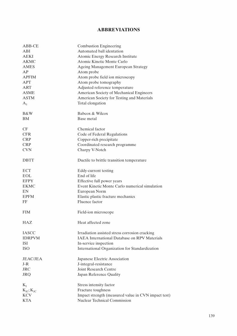
ABBREVIATIONS
ABB-CE Combustion EngineeringABI Automated ball identationAEKI Atomic Energy Research InstituteAKMC Atomic Kinetic Monte Carlo AMES Ageing Management European StrategyAP Atom probeAPFIM Atom probe field ion microscopyAPT Atom probe tomographyART Adjusted reference temperatureASME American Society of Mechanical EngineersASTM American Society for Testing and MaterialsA5 Total elongation
B&W Babcox & WilcoxBM Base metal
CF Chemical factorCFR Code of Federal RegulationsCRP Copper-rich precipitateCRP Coordinated research programmeCVN Charpy V-Notch
DBTT Ductile to brittle transition temperature
ECT Eddy-current testingEOL End of lifeEFPY Effective full power yearsEKMC Event Kinetic Monte Carlo numerical simulationEN European NormEPFM Elastic plastic fracture mechanicsFF Fluence factor
FIM Field-ion microscope
HAZ Heat affected zone
IASCC Irradiation assisted stress corrosion crackingIDRPVM IAEA International Database on RPV MaterialsISI In-service inspectionISO International Organization for Standardization
JEAC/JEA Japanese Electric AssociationJ-R J-integral-resistanceJRC Joint Research CentreJRQ Japan Reference Quality
KI Stress intensity factorKIC; KJC Fracture toughnessKCV Impact strength (measured value in CVN impact test)KTA Nuclear Technical Commission
139

KWU Kraftwerk Union AG
LBP Late blooming phaseLEFM Linear elastic fracture mechanicsLOCA Loss of coolant accidentLTOP Low temperature overpressure protectionLVDT Linear-variable displacement transducer
MMC Metropolis Monte Carlo numerical simulationMNP Manganese–nickel-rich precipitate
NDE Non-destructive examinationNDT Non-destructive testingNDT Nil ductility temperatureNRC Nuclear Regulatory CommissionNSSS Nuclear steam supply system
OKMC Object Kinetic Monte Carlo numerical simulationORNL Oak Ridge National Laboratory
PA Positron annihilationPAS Positron annihilation spectroscopyPCVN Pre-cracked Charpy V-notch specimenPKA Primarily knock-on atomPSI Pre-service inspectionP–T Pressure–temperaturePTS Pressurized thermal shock
Rp0.2 Yield strengthRm Ultimate tensile strengthRT Rate Theory numerical simulationRTNDT Reference temperature
SANS Small angle neutron scatteringSAW Seam arc weldingSI Structural integritySIA Self-interstitial atomSKA Secondary knock-on atomSMAW Shielded metal arc weldingSQUID Superconducting Quantum Interference DeviceSSC System, structure and component
TEM Transmission electron microscopyTEP Thermo-electric powerTirr Irradiation temperatureTk Ductile–brittle transition temperature; critical temperature of brittlenessTk0 Initial ductile-brittle transition temperatureTT Transition temperatureTÜV Technical Monitoring AssociationTWG-LMNPP Technical Working Group on Life Management of NPPs
USE Upper shelf energy
140

VTR Virtual test reactor
WM Weld metal
141

.

CONTRIBUTORS TO DRAFTING AND REVIEW
Ballesteros, A. Tecnatom, Spain
Brumovský, M. Nuclear Research Institute Řež, Czech Republic
Davies, L.M. LMD Consultancy, United Kingdom
Debarberis, L. Institute for Energy EC–Joint Research Centre, Netherlands
Jumel, S. Electricité de France, France
Kang, K.S. International Atomic Energy Agency
Kryukov, A. Atomstroyexport, Russian Federation
Kupca, L. International Atomic Energy Agency
Langer, R. Framatome ANP, Germany
Lott, R. Westinghouse, USA
Nanstad, R. Oak Ridge National Laboratory, USA
Server, W. Advanced Technology Innovation Consulting, USA
Sevini, F. Institute for Energy EC–Joint Research Centre, Netherlands
Soneda, N. Central Research Institute of Electric Power Industry, Japan
Van Duysen, J.C. Electricité de France, France
143

Key
Examples
BP
: Ba
sic
Prin
cipl
es
NG
-G-3
.1:
Nuc
lear
Gen
eral
(NG
), G
uide
, Nuc
lear
Infra
stru
ctur
e an
d Pl
anni
ng (t
opic
3),
#1
O:
Obj
ectiv
es
NP
-T-5
.4:
Nuc
lear
Pow
er (N
P),
Rep
ort (
T),
Res
earc
h R
eact
ors
(topi
c 5),
#4
G:
Gui
des
NF
-T-3
.6:
Nuc
lear
Fue
l (N
F),
Rep
ort (
T),
Spen
t Fue
l Man
agem
ent a
nd R
epro
cess
ing,
#6
T:
Tech
nica
l Rep
orts
N
W-G
-1.1
: R
adio
activ
e W
aste
Man
agem
ent a
nd D
ecom
mis
sion
ing
(NW
), G
uide
, N
os. 1-6
: To
pic
desi
gnat
ions
Rad
ioac
tive
Was
te (t
opic
1),
#1
#:
Gui
de o
r Rep
ort n
umbe
r (1,
2, 3
, 4, e
tc.)
Str
uc
ture
of
the
IA
EA
Nu
cle
ar E
ne
rg
y S
erie
s
Ra
dio
ac
tiv
e W
as
te M
an
ag
em
en
t
an
d D
ec
om
mis
sio
nin
g O
bje
cti
ve
s
NW
-O
Nu
cle
ar F
ue
l C
yc
le O
bje
cti
ve
s
NF
-O
Nu
cle
ar P
ow
er O
bje
cti
ve
s
NP
-O
Nu
cle
ar G
en
era
l O
bje
cti
ve
s
NG
-O
Nu
cle
ar E
ne
rg
y B
as
ic P
rin
cip
les
NE
-BP
1. M
an
ag
em
en
t S
yste
ms
NG
-G-1
.#
NG
-T-1
.#
2. H
um
an
Reso
urc
es
NG
-G-2
.#
NG
-T-2
.#
3. N
ucle
ar
Infr
astr
uctu
re a
nd
Pla
nn
ing
NG
-G-3
.#
NG
-T-3
.#
4. E
co
no
mic
s
NG
-G-4
.#
NG
-T-4
.#
5. E
nerg
y S
yste
m A
naly
sis
NG
-G-5
.#
NG
-T-5
.#
6. K
no
wle
dg
e M
an
ag
em
en
t
NG
-G-6
.#
NG
-T-6
.#
1. Tech
no
log
y D
evelo
pm
en
t
NP
-G-1
.#
NP
-T-1
.#
2. D
esig
n a
nd
Co
nstr
ucti
on
of
Nu
cle
ar
Po
wer
Pla
nts
NP
-G-2
.#
NP
-T-2
.#
3. O
pera
tio
n o
f N
ucle
ar
Po
wer
Pla
nts
NP
-G-3
.#
NP
-T-3
.#
4. N
on
-Ele
ctr
ical A
pp
licati
on
s
NP
-G-4
.#
NP
-T-4
.#
5. R
esearc
h R
eacto
rs
NP
-G-5
.#
NP
-T-5
.#
1. R
eso
urc
es
NF
-G-1
.#
NF
-T-1
.#
2. F
uel E
ng
ineeri
ng
an
d P
erf
orm
an
ce
NF
-G-2
.#
NF
-T-2
.#
3. S
pen
t F
uel M
an
ag
em
en
t an
d R
ep
rocessin
g
NF
-G-3
.#
NF
-T-3
.#
4. F
uel C
ycle
s
NF
-G-4
.#
NF
-T-4
.#
5. R
esearc
h R
eacto
rs —
Nu
cle
ar
Fu
el C
ycle
NF
-G-5
.#
NF
-T-5
.#
1. R
ad
ioacti
ve W
aste
Man
ag
em
en
t
NW
-G-1
.#
NW
-T-1
.#
2. D
eco
mm
issio
nin
g o
f N
ucle
ar
Facilit
ies
NW
-G-2
.#
NW
-T-2
.#
3. S
ite R
em
ed
iati
on
NW
-G-3
.#
NW
-T-3
.#
144

Basic Principles
Objectives
IAEA Nuclear Energy Series
Technical Reports
Integrity of Reactor Pressure Vessels in Nuclear Power Plants: Assessment of Irradiation Embrittlement Effects in Reactor Pressure Vessel Steels
No. NP-T-3.11
Guides
IAEA Nuclear Energy Series No. No. NP-T-3.11Integrity of Reactor Pressure Vessels in Nuclear Pow
er Plants: Assessment of Irradiation Em
brittlement Effects in Reactor Pressure Vessel Steels
INTERNATIONAL ATOMIC ENERGY AGENCYVIENNA
ISBN 978–92–0–101709–3ISSN 1995–7807
156 pages, 9mm
P1382_covI-IV.indd 1 2009-05-05 11:14:48