no.: 9 6964 01e ramirentinstrukcijas.ramirent.lv/instrukcijas/kaeser/kompresors... · ·...
TRANSCRIPT

Service Manual
Reciprocating compressor
Premium car D No.: 9_6964 01E
Manufacturer:
KAESER KOMPRESSOREN GmbH
96410 Coburg • PO Box 2143 • GERMANY • Tel. +49-(0)9561-6400 • Fax +49-(0)9561-640130
http://www.kaeser.com
RAMIRENT

Original instructions/KKW/PPCA 1.01 en SBA-KOLBEN-ANLAGE 1-STUFIG
RAMIRENT

1 Regarding this document1.1 Using the Document ......................................................................................................... 11.2 Further Documents .......................................................................................................... 11.3 Copyright .......................................................................................................................... 11.4 Symbols and Identification ............................................................................................... 1
1.4.1 Warnings ............................................................................................................. 11.4.2 Other instructions and symbols .......................................................................... 2
2 Technical Specification2.1 Nameplate ........................................................................................................................ 32.2 Weight .............................................................................................................................. 32.3 Compressor block ............................................................................................................ 32.4 Ambient Conditions .......................................................................................................... 42.5 Pressure switch setting .................................................................................................... 42.6 Pressure ........................................................................................................................... 42.7 Sound emission ................................................................................................................ 52.8 Motor power and speed ................................................................................................... 52.9 Compressor oil recommendations ................................................................................... 5
2.9.1 Compressor oil charge ........................................................................................ 62.10 Power Supply ................................................................................................................... 6
2.10.1 Three-phase power supply ................................................................................. 62.11 Network Conditions ......................................................................................................... 7
2.11.1 Network conditions at 400V/3/50Hz .................................................................... 72.12 Machine duty cycle ........................................................................................................... 7
3 Safety and Responsibility3.1 Basic Information ............................................................................................................. 93.2 Specified Use ................................................................................................................... 93.3 Improper Use ................................................................................................................... 93.4 User's Responsibilities ..................................................................................................... 9
3.4.1 Observe statutory and universally accepted regulations. ................................... 93.4.2 Qualified personnel ............................................................................................. 103.4.3 Adherence to inspection schedules and accident prevention regulations .......... 10
3.5 Dangers ............................................................................................................................ 113.5.1 Safely dealing with sources of danger ................................................................ 123.5.2 Safe machine operation ...................................................................................... 133.5.3 Organisational Measures .................................................................................... 14
3.6 Safety Devices ................................................................................................................. 143.7 Safety Signs ..................................................................................................................... 153.8 Information signs .............................................................................................................. 153.9 In Emergency ................................................................................................................... 16
3.9.1 Fire fighting ......................................................................................................... 163.9.2 Remove any compressor oil from your person. .................................................. 16
3.10 Warranty ........................................................................................................................... 163.11 Environmental Protection ................................................................................................. 17
4 Design and Function4.1 Outline of the machine ..................................................................................................... 18
4.1.1 Function .............................................................................................................. 184.2 Operating modes and control modes ............................................................................... 19
4.2.1 Operating modes ................................................................................................ 194.2.2 Control modes .................................................................................................... 19
4.3 Safety Devices ................................................................................................................. 19
5 Installation and Operating Conditions5.1 Safety ............................................................................................................................... 20
Contents
No.: 9_6964 01EService Manual Reciprocating compressor Premium car D i
RAMIRENT

5.2 Installation conditions ....................................................................................................... 20
6 Installation6.1 Safety ............................................................................................................................... 216.2 Reporting Transport Damage ........................................................................................... 216.3 Fitting the Antivibration Mounts ........................................................................................ 216.4 Compressed Air Connection ............................................................................................ 226.5 Connecting the Power Supply .......................................................................................... 22
7 Initial Start-up7.1 Safety ............................................................................................................................... 247.2 Instructions to be observed before commissioning or recommissioning .......................... 247.3 Checking positioning and operating conditions ................................................................ 257.4 Motor overload protection ................................................................................................ 25
7.4.1 Motor protection setting with direct online starting .............................................. 257.5 Checking direction of rotation ........................................................................................... 267.6 Starting the machine for the first time .............................................................................. 267.7 Measuring the Air Receiver Filling Time .......................................................................... 267.8 Setting network pressure ................................................................................................. 277.9 Setting the filter regulator ................................................................................................. 28
8 Operation8.1 Switching on and off ......................................................................................................... 29
9 Fault Recognition and Rectification9.1 Basic Information ............................................................................................................. 309.2 Alarms .............................................................................................................................. 30
10 Maintenance10.1 Safety ............................................................................................................................... 3210.2 Maintenance Schedule ..................................................................................................... 32
10.2.1 Logging maintenance work ................................................................................. 3210.2.2 Regular maintenance tasks ................................................................................ 3310.2.3 Oil change interval .............................................................................................. 3310.2.4 Regular service tasks ......................................................................................... 33
10.3 Air cooler maintenance .................................................................................................... 3410.3.1 Cleaning the air cooler ........................................................................................ 34
10.4 Air filter maintenance ....................................................................................................... 3510.5 Drive Motor Maintenance ................................................................................................. 3610.6 Checking the Oil Level ..................................................................................................... 3610.7 Topping up the compressor oil ......................................................................................... 3610.8 Changing the Compressor Oil .......................................................................................... 3710.9 Checking the pressure relief valve ................................................................................... 38
10.9.1 Pressure relief valve in the collecting pipe .......................................................... 3810.9.2 Air receiver pressure relief valve ........................................................................ 39
10.10 Air Receiver ...................................................................................................................... 3910.11 Venting the machine (de-pressurising) ............................................................................ 4010.12 Maintaining the check valve ............................................................................................. 4110.13 Maintenance of the pressure switch unloading valve ....................................................... 4110.14 Cleaning the filter regulator .............................................................................................. 4210.15 Cylinder Head and Valves ................................................................................................ 43
10.15.1 Checking the cylinder head and valves .............................................................. 4310.16 Document maintenance and service work. ...................................................................... 44
11 Spares, Operating Materials, Service11.1 Note the Nameplate ......................................................................................................... 4511.2 Ordering consumable parts and operating fluids/materials .............................................. 45
Contents
iiService Manual Reciprocating compressor Premium car D No.: 9_6964 01E
RAMIRENT

11.3 KAESER AIR SERVICE .................................................................................................. 4511.4 Service Addresses ........................................................................................................... 4611.5 Spare Parts for Service and Repair ................................................................................. 46
12 Decommissioning, Storage and Transport12.1 De-commissioning ............................................................................................................ 4712.2 Packing ............................................................................................................................ 4712.3 Storage ............................................................................................................................. 4812.4 Transporting ..................................................................................................................... 48
12.4.1 Safety .................................................................................................................. 4812.5 Disposal ........................................................................................................................... 48
13 Annex13.1 Dimensional Drawing ....................................................................................................... 4913.2 Electrical Diagram ............................................................................................................ 51
Contents
No.: 9_6964 01EService Manual Reciprocating compressor Premium car D iii
RAMIRENT

Contents
ivService Manual Reciprocating compressor Premium car D No.: 9_6964 01E
RAMIRENT

Fig. 1 Location of safety signs .............................................................................................................. 15Fig. 2 Machine layout ........................................................................................................................... 18Fig. 3 Fitting the antivibration mounts .................................................................................................. 22Fig. 4 Compressed air connection ........................................................................................................ 22Fig. 5 Setting network pressure ............................................................................................................ 27Fig. 6 Setting the filter regulator ........................................................................................................... 28Fig. 7 Switching on and off ................................................................................................................... 29Fig. 8 Cleaning the air cooler ............................................................................................................... 34Fig. 9 Air filter maintenance .................................................................................................................. 35
Fig. 10 Checking the Oil Level ............................................................................................................... 36Fig. 11 Changing the compressor oil ...................................................................................................... 37Fig. 12 Checking the collecting pipe relief valve .................................................................................... 38Fig. 13 Checking pressure relief valve on the air receiver ..................................................................... 39Fig. 14 Venting the machine ................................................................................................................. 40Fig. 15 Cleaning the check valve ........................................................................................................... 41Fig. 16 Maintenance of the pressure switch unloading valve ................................................................. 42Fig. 17 Cleaning the Filter Regulator ...................................................................................................... 43Fig. 18 Consumable parts ...................................................................................................................... 45
List of Illustrations
No.: 9_6964 01EService Manual Reciprocating compressor Premium car D v
RAMIRENT

List of Illustrations
viService Manual Reciprocating compressor Premium car D No.: 9_6964 01E
RAMIRENT

Tab. 1 The levels of danger and their meaning ..................................................................................... 2Tab. 2 Nameplate .................................................................................................................................. 3Tab. 3 Weight ........................................................................................................................................ 3Tab. 4 Compressor block ...................................................................................................................... 3Tab. 5 Ambient Conditions .................................................................................................................... 4Tab. 6 Pressure switch setting .............................................................................................................. 4Tab. 7 Air receiver pressure relief valve setting .................................................................................... 4Tab. 8 Collecting pipe relief valve setting .............................................................................................. 4Tab. 9 Sound Pressure Level ................................................................................................................ 5
Tab. 10 Power and speeds ...................................................................................................................... 5Tab. 11 Permissible starting frequency ................................................................................................... 5Tab. 12 Compressor oil recommendations .............................................................................................. 5Tab. 13 Compressor oil charge ............................................................................................................... 6Tab. 14 Connection details 230V/3/50Hz ................................................................................................ 7Tab. 15 Connection details 400V/3/50Hz ............................................................................................... 7Tab. 16 Network impedance .................................................................................................................... 7Tab. 17 Machine duty cycle ..................................................................................................................... 8Tab. 18 Inspection intervals according to Ordinance on Industrial Safety and Health ............................ 11Tab. 19 Safety Signs ............................................................................................................................... 15Tab. 20 Information signs ........................................................................................................................ 16Tab. 21 Re-commissioning after storage ................................................................................................. 25Tab. 22 Checklist of installation conditions .............................................................................................. 25Tab. 23 Air receiver filling time ................................................................................................................ 27Tab. 24 Changing the pressure switch setting ........................................................................................ 28Tab. 25 Faults and remedies ................................................................................................................... 30Tab. 26 Regular maintenance tasks ........................................................................................................ 33Tab. 27 Oil change intervals .................................................................................................................... 33Tab. 28 Regular service tasks ................................................................................................................. 33Tab. 29 Logged maintenance tasks ........................................................................................................ 44Tab. 30 Consumable parts ...................................................................................................................... 45
List of Tables
No.: 9_6964 01EService Manual Reciprocating compressor Premium car D vii
RAMIRENT

List of Tables
viiiService Manual Reciprocating compressor Premium car D No.: 9_6964 01E
RAMIRENT

1 Regarding this document1.1 Using the Document
The service manual is part of the machine. It describes the machine as it was at the time of firstdelivery after manufacture.➤ Keep the service manual in a safe place throughout the life of the machine.➤ Pass the manual on to the next owner/user of the machine.➤ Ensure that all amendments received are entered in the manual.➤ Enter details from the machine nameplate and individual items of equipment in the table in chap‐
ter 2.
1.2 Further DocumentsIncluded with this service manual are additional documents intended to assist in the safe operationof the machine:■ Certificate of acceptance / operating instructions for the pressure vessel.■ Manufacturer's declaration / declaration of conformity in accordance with applicable directives.
Missing documents can be requested from KAESER.➤ Make sure all documents are complete and observe the instructions contained in them.➤ Make sure you give the data from the nameplate when ordering documents.
1.3 CopyrightThis service manual is protected by copyright. Any queries regarding the use or duplication of thisdocumentation should be referred to KAESER. We would be pleased to help you in using the infor‐mation to meet your unique requirements.
1.4 Symbols and Identification
1.4.1 Warnings
Warning notices indicate three levels of danger signified by the signal word.■ DANGER■ WARNING■ CAUTION
DANGERThese show the kind of danger and its source!The possible consequences of ignoring a warning are shown here.The word "Danger" indicates that death or severe injury can result from ignoring the instruction.➤ The measures required to protect yourself from danger are shown here.
1 Regarding this document1.1 Using the Document
No.: 9_6964 01EService Manual Reciprocating compressor Premium car D 1
RAMIRENT

➤ Always read and comply with warning instructions.
Signal word Meaning Consequences of non-observance
DANGER Warns of an imminent threat of danger Death or serious injury may result
WARNING Warns of possible danger Death or serious injury are possible
CAUTION Warns of a possibly dangerous situa‐tion
Light injuries or material damage are possible
Tab. 1 The levels of danger and their meaning
1.4.2 Other instructions and symbols
This symbol refers to particularly important information.
Material Here you will find details on special tools, operating materials or spare parts.
Precondition Here you will find conditional requirements necessary to carry out the task.Here conditions relevant to safety are named that will help you to avoid dangerous situations.
➤ This symbol is is placed by lists of actions comprising one stage of a task.In lists of actions with several stages the sequence of actions is numbered.
Information referring to potential problems are identified by a question mark.The cause is named in the help text➤ ... and a remedy given.
This symbol refers to important information or measures concerning environmental protection.
1 Regarding this document1.4 Symbols and Identification
2Service Manual Reciprocating compressor Premium car D No.: 9_6964 01E
RAMIRENT

2 Technical Specification2.1 Nameplate
The machine's nameplate provides the model designation and important technical information.➤ Enter here the nameplate data as a reference:
Features Value
Reciprocating Compressor
Material number
Serial number
Year of manufacture
Maximum working pressure
inlet volume
Rated voltage
Synchronous speed
Rated power (*) **
Ambient temperature
* Power requirement at the compressor drive shaft (EN 1012–1)
** Motor shaft output power (EN 60034-1 VDE 0530)
Tab. 2 Nameplate
2.2 WeightThe weight indicated is the maximum weight. The actual weight depends on equipment fitted.
Model Weight [kg]
Premium 660/70 118
Tab. 3 Weight
2.3 Compressor blockModel Theoretical displace‐
ment [l/min]FAD at 6 bar [l/min] Number of cylinders
KC 630 660 440 2
Tab. 4 Compressor block
2 Technical Specification2.1 Nameplate
No.: 9_6964 01EService Manual Reciprocating compressor Premium car D 3
RAMIRENT

2.4 Ambient ConditionsInstallation
Maximum altitude AMSL*[m]
1000
Permissible ambient tem‐perature [°C]
5–35
* Higher altitudes are permissible only after consultation with the manufacturer.
Tab. 5 Ambient Conditions
2.5 Pressure switch settingSpecified pressures are factory set.Customer-specific settings may differ.
Characteristic Value
Cut-in pressure [bar] 7
Cut-out pressure [bar] 9
Pressure differential Δp[bar]
2
Minimum setting range[bar]*
3/4
*Minimum adjustment range: Cut-in pressure/cut-out pressure
Tab. 6 Pressure switch setting
2.6 PressureAir receiver pressure relief valve
Characteristic Value
Maximum working over‐pressure [bar]
10
Pressure relief valve acti‐vating pressure [bar]
11
Tab. 7 Air receiver pressure relief valve setting
Pressure relief valve in the collecting pipe
Characteristic Value
Maximum working over‐pressure [bar]
10
Pressure relief valve acti‐vating pressure [bar]
12.5
Tab. 8 Collecting pipe relief valve setting
2 Technical Specification2.4 Ambient Conditions
4Service Manual Reciprocating compressor Premium car D No.: 9_6964 01E
RAMIRENT

2.7 Sound emissionSound power level■ in accordance with 2000/14/EG and ISO 3744
Emission sound pressure level■ calculated from the measured average sound power level (directive 2000/14/EG, Sound Meas‐
uring Standard ISO 3744) according to EN ISO 11203:1995 6.2.3d at distance d = 1 m, Q2 = Log‐arithmic surface ratio: dB.
EC type approval:■ Certificate No.: OR/2551/SZ03
Model Sound pressure level [dB(A)] Emission soundpressure level
[dB(A)]
Logarithmic sur‐face ratio [dB]Measured Guaranteed
Premium 660/70 91 97 77 14.6
Tab. 9 Sound Pressure Level
2.8 Motor power and speed➤ Read off the enclosure protection rating from the motor nameplate and enter in the table:
Compressor block Rated power [kW] Synchronous speed[min-1] (50 Hz)
Degree of protection
KC 630 3.0 1500
Tab. 10 Power and speeds
Permissible starting frequency
➤ Read-off the permissible starting frequency of the motor from the table below.
Rated power [kW] Permissible starting frequency [1/h]
3.0 15
Tab. 11 Permissible starting frequency
2.9 Compressor oil recommendationsThe standard compressor oil is VDL 150.For special applications FGP oil is used and the machine carries a sticker indicating this.Information on ordering compressor oil is found in chapter 11.➤ Mark the oil that your compressor contains in the table below.
Standard oil Special oil
Oil type VDL 150 FGP
* Cool to moderate ambient temperatures, low humidity, low to average duty cycle.
2 Technical Specification2.7 Sound emission
No.: 9_6964 01EService Manual Reciprocating compressor Premium car D 5
RAMIRENT

Standard oil Special oil
Application: Standard oil for all applicationsexcept in connection with food‐stuffs.
Specially for use in compressorswhere the air comes in directcontact with foodstuff.
maximal permissible fluidchange interval in operatinghours/years
1000/1* 1000/2*
Oil contained in my compressor
* Cool to moderate ambient temperatures, low humidity, low to average duty cycle.
Tab. 12 Compressor oil recommendations
2.9.1 Compressor oil charge
Model Total charge [l] Topping up volume [l]
(max. - min.)
KC 630 1.2 0.22
Tab. 13 Compressor oil charge
2.10 Power SupplyBasic requirements
The machine is designed for a power supply conforming to EN 60204–1 (IEC 60204–1), section 4.3.In the absence of other user-specified conditions, the limits laid down in this standard must be adheredto.It is recommended that the supplier and user confer and agree on the basis of the EN 60204–1,Annex B.
2.10.1 Three-phase power supply
The machine requires a symmetrical three-phase power supply.In a symmetrical three-phase supply the phase angles and voltages are all the same.This machine may only be supplied from an earthed TN or TT three-phase supply in which the neutralpoint is earthed.Connection to an IT supply is not permitted without taking further measures (earth leak detection,etc.).
Further information When connecting to a European 400 V/3/50 Hz power supply the requirements in chapter 2.11 arealso to be observed.See electrical diagram in 13.2.
2.10.1.1 Power supply specifications
The following conductor cross-sections (copper multicore) and fusing (industrial fuses, slow blow) aregiven according to VDE 0100, parts 430 and 523 (IEC 60364–4–43) for ambient temperatures from30 °C and laying method C.
2 Technical Specification2.10 Power Supply
6Service Manual Reciprocating compressor Premium car D No.: 9_6964 01E
RAMIRENT

➤ The conductor cross-sections should be changed accordingly if other conditions prevail.
Other conditions would include:■ higher temperature■ other cable laying method■ cable lengths >50 m
Rated power supply: 230V±10%/3/50Hz
Model Mains fusing [A] Supply cable [mm2] Current drawn [A]
Premium 660/70 20 4 x 2.5 11.8
Tab. 14 Connection details 230V/3/50Hz
Rated power supply: 400V±10%/3/50Hz
Model Mains fusing [A] Supply cable [mm2] Current drawn [A]
Premium 660/70 16 4 x 2.5 6.8
Tab. 15 Connection details 400V/3/50Hz
2.11 Network ConditionsThe machines listed in the table below are intended for use in changing locations.No interference with other devices is to be expected with network impedance less than Zmax [Ohm].In general, the maximum permissible network impedance will not be exceeded if the machine issupplied at the transfer point with a rated current of Iäqiv .
2.11.1 Network conditions at 400V/3/50Hz
Model Starts [1/h] Zmax [Ω] Iäqiv [A]
Premium 660 6 0.153 35
12 0.110 50
18 0.091 50
Tab. 16 Network impedance
2.12 Machine duty cycleCalculating the cycling period:
Cycling time = time under load + time at standstillCalculating the duty cycle:
Duty cycle [%] = time under loadtime under load + standstill time
x 100
Example
12 minutes20 minutes
x 100 % = 60 %
2 Technical Specification2.11 Network Conditions
No.: 9_6964 01EService Manual Reciprocating compressor Premium car D 7
RAMIRENT

The following values are valid for:■ 20 °C ambient temperature■ 30 % relative humidity■ 1013 mbar air pressure
Permissible duty cycle2 [%] Cycling period1 [min]
Premium 660/70 ≤ 70 4–40
Tab. 17 Machine duty cycle
2 Technical Specification2.12 Machine duty cycle
8Service Manual Reciprocating compressor Premium car D No.: 9_6964 01E
RAMIRENT

3 Safety and Responsibility3.1 Basic Information
The machine is manufactured to the latest engineering standards and acknowledged safety regula‐tions. Nevertheless, dangers can arise through its operation:■ danger to life and limb of the operator or third parties,■ impairments to the machine and other material assets.
DANGERDisregard of these instructions can result in serious injury.➤ Read the service manual carefully and take notice of the contents for safe machine operation.
➤ Use this machine only if it is in a technically perfect condition and only for the purpose for whichit is intended; observe all safety measures and the instructions in the service manual.
➤ Immediately rectify (have rectified) any faults that could be detrimental to safety.
3.2 Specified UseThe machine is intended solely for generating compressed air for industrial use. Any other use isconsidered incorrect. The manufacturer is not liable for any damages that may result therefrom. Theuser alone is liable for any risks incurred.➤ Keep to the specifications listed in this service manual.➤ Operate the machine only within its performance limits and under the permitted ambient condi‐
tions.➤ Do not use compressed air for breathing purposes unless it is specifically treated.➤ Do not use compressed for any application that will bring it into direct contact with foodstuffs
unless it is specifically treated.
3.3 Improper Use➤ Never direct compressed air at persons or animals.➤ Use hot cooling air for heating purposes only if there is no risk to the health of humans or animals.
If necessary, hot cooling air should be treated by suitable means.➤ Do not allow the machine to breath in toxic, acidic, flammable of explosive gases or vapours.➤ Do not operate the machine in areas in which specific requirements with regard to explosion
protection are in force.
3.4 User's Responsibilities
3.4.1 Observe statutory and universally accepted regulations.
This is, for example, nationally applied European directives and/or valid national legislation, safetyand accident prevention regulations.➤ Observe relevant statutory and accepted regulations during installation, operation and mainte‐
nance of the machine.
3 Safety and Responsibility3.1 Basic Information
No.: 9_6964 01EService Manual Reciprocating compressor Premium car D 9
RAMIRENT

3.4.2 Qualified personnel
These are people who, by virtue of their training, knowledge and experience as well as their knowl‐edge of relevant regulations can assess the work to be done and recognise the possible dangersinvolved.
Authorised operators possess the following qualifications:■ are of legal age,■ are conversant with and adhere to the safety instructions and sections of the service manual
relevant to operation,■ have received adequate training and authorisation to operate electrical and compressed air de‐
vices.
Authorised installation and maintenance personnel have the following qualifications:■ are of legal age,■ have read, are conversant with and adhere to the safety instructions and sections of the service
manual applicable to installation and maintenance,■ are fully conversant with the safety concepts and regulations of electrical and compressed air
engineering,■ are able to recognise the possible dangers of electrical and compressed air devices and take
appropriate measures to safeguard persons and property,■ have received adequate training and authorisation for the safe installation and maintenance on
this equipment.
➤ Ensure that operating, installation and maintenance personnel are qualified and authorised tocarry out their tasks.
3.4.3 Adherence to inspection schedules and accident prevention regulations
The machine is subject to local inspection schedules.
Examples of German operation
➤ Recurring inspections according to BGR 500, chapter 2.11.The user must ensure that, for machines with motor power above 0.5 kW, safety devices arechecked for function as required or at least annually.
3 Safety and Responsibility3.4 User's Responsibilities
10Service Manual Reciprocating compressor Premium car D No.: 9_6964 01E
RAMIRENT

➤ Keep to inspection intervals in accordance with the Ordinance on Industrial Safety and Healthwith maximum intervals as laid down in §15.
The inspection intervals are laid down in the technical specification for the air receiver. Inspec‐tion intervals are dependent on the pressure/volume product of the air receiver, i.e. max per‐missible pressure (PS) in bar, times the receiver volume (V) in litres.Example: volume V = 90 litres, max. permissible pressure PS = 11 bar; pressure/volume product= 990.
Inspection Inspection interval Inspecting authority
Installation and equip‐ment inspection
Before commissioning if pressurePS x volume V ≤ 200
Competent person(e. g. KAESER Service Techni‐cian)
Compressors with type approval in‐spection (Ordinance on IndustrialSafety and Health, annex 5 no. 25)PS x V ≤ 1000
Competent person(e. g. KAESER Service Techni‐cian)
Before commissioning ifPS x V > 200
Approved supervisory body
Internal inspection Every 5 years after installation or thelast inspection ifPS x V ≤ 1000
Competent person(e. g. KAESER Service Techni‐cian)
Every 5 years after installation or thelast inspection ifPS x V > 1000
Approved supervisory body
Strength test Every 10 years after installation or thelast inspection ifPS x V ≤ 1000
Competent person(e. g. KAESER Service Techni‐cian)
Every 10 years after installation or thelast inspection ifPS x V > 1000
Approved supervisory body
* The inspection interval is determined by the user in consultation with the approved supervisorybody. The responsible body is to be notified not later than 6 months after the inspection carried outbefore commissioning (if pressure x volume V > 1000). Intervals given are the maximum in eachcase.
Tab. 18 Inspection intervals according to Ordinance on Industrial Safety and Health
3.5 DangersBasic Information
Information concerning the various forms of danger that can arise during machine operation are foundhere.Basic safety instructions are found in this service manual at the beginning of each chapter in thesection entitled 'Safety'.Warning instructions are found before a potentially dangerous task.
3 Safety and Responsibility3.5 Dangers
No.: 9_6964 01EService Manual Reciprocating compressor Premium car D 11
RAMIRENT

3.5.1 Safely dealing with sources of danger
Information concerning the various forms of danger that can arise during machine operation are foundhere.
Electricity
➤ Allow only qualified and authorised electricians or trained personnel under the supervision of aqualified and authorised electrician to carry out work on electrical equipment according to elec‐trical engineering regulations .
➤ Before every start-up, the user must make sure there is adequate protection against electric shockfrom direct or indirect contact.
➤ Before starting any work on electrical equipment:Switch off and lock out the power supply disconnecting device and check that no voltage ispresent.
➤ Switch off any external power sources.These could be connections to floating relay contacts or electrical machine heating, for example.
➤ Use fuses corresponding to machine power.➤ Check regularly that all electrical connections are tight and in order.
Forces of compression
Compressed air is contained energy. Uncontrolled release of this energy can cause serious injury ordeath. The following information concerns work on components that could be under pressure.➤ Close shut-off valves or otherwise isolate the machine from the air main to ensure that no com‐
pressed air can flow back into the machine.➤ Vent all pressurized components and chambers completely.➤ Do not carry out welding, heat treatment or mechanical modifications to pressurized components
(e.g. pipes and vessels) as this influences the component's resistance to pressure.The safety of the machine is then no longer ensured.
Compressed air quality
➤ Never directly inhale compressed air.➤ Use appropriate systems for air treatment before using the compressed air from this machine as
breathing air and/or for the processing of foodstuffs.➤ Use compressor oil compatible with foodstuffs if compressed air can come into contact with them.
Spring force
Springs under tension or compression represent contained energy. Uncontrolled release of this en‐ergy can cause serious injury or death.The non-return valve is spring loaded.➤ Do not open or dismantle the valve.
Rotating components
Touching the fan while the machine is running can result in serious injury.➤ Do not open the enclosure while the machine is switched on.➤ Switch off and lock out the power supply disconnecting device and check that no voltage is
present.
3 Safety and Responsibility3.5 Dangers
12Service Manual Reciprocating compressor Premium car D No.: 9_6964 01E
RAMIRENT

➤ Wear close-fitting clothes and a hair net if necessary.➤ Make sure all covers and safety guards are in place and secured before starting.
Heat
➤ Avoid contact with hot components.These include, for example, compressor blocks, compressed air pipes, coolers, motors and ma‐chine heaters.
➤ Wear protective clothing.➤ If welding is carried out on or near the machine, take adequate measures to prevent sparks or
heat from igniting oil vapours or parts of the machine.
Noise
➤ Operate the machine only with full soundproofing.➤ Wear hearing protection if necessary.
The pressure relief valve blowing off can be particularly loud.
Operating materials
➤ Strictly forbid fire, open flame and smoking.➤ Follow safety regulations when dealing with lubricants and chemical substances.➤ Avoid contact with skin and eyes.➤ Do not inhale oil mist and vapours.➤ Do not eat or drink while handling cooling and lubricating fluids.➤ Keep suitable fire extinguishing agents ready for use.➤ Use only KAESER approved operating materials.
Unsuitable spare parts
➤ Use only spare parts approved by the manufacturer for use in this machine.Unsuitable spare parts compromise the safety of the device.
➤ Use only genuine KAESER pressure components.
Conversion or modification of the machine
➤ Do not permit conversion or modification of the machine as this can compromise function andsafe working.
Extension or modification of the compressed air system
➤ Extension or modification of the compressor station:Check the blow-off capacity of pressure relief valves on air receivers and compressed air linesbefore installing any new machines.
➤ If the blow-off capacity is insufficient:Install pressure relief valves with larger blow-off capacity.
3.5.2 Safe machine operation
Information on safe conduct when handling the machine is found here.
3 Safety and Responsibility3.5 Dangers
No.: 9_6964 01EService Manual Reciprocating compressor Premium car D 13
RAMIRENT

Transport
➤ Use suitable lifting gear that conforms to local safety regulations.➤ Allow transport only by personnel trained in the safe movement of goods.➤ Attach lifting gear only to suitable lifting points.➤ Note the centre of gravity to avoid danger of the machine tipping over.➤ Make sure the danger zone is clear of personnel.
Installation
➤ Install the machine in a suitable compressor room.➤ If installed outdoors, the machine must be protected from frost, direct sunlight, dust, rain and
splashing water.➤ Do not operate in areas in which specific requirements with regard to explosion protection are in
force.For instance, the requirements of ATEX directive 94/9/EC "Equipment and Protective Systemsintended for use in Potentially Explosive Atmospheres".
➤ Ensure adequate ventilation.➤ Ensure that required ambient conditions are maintained with regard to:
■ Ambient temperature and humidity■ Clean inlet air with no damaging contaminants.■ Inlet air free of explosive or chemically unstable gases or vapours.■ inlet air free of acid/alkaline forming substances, particularly ammonia, chlorine or hydrogen
sulphide.➤ Do not position the machine in warm exhaust air from other machines.➤ Ensure accessibility so that all work on the machine can be carried out without danger or hin‐
drance.
Decommissioning, storage, disposal
➤ Drain out fluids and dispose of according to environmental regulations.These include, for example, lubricating oil and compressor oil.
➤ Dispose of the machine in accordance with local environmental regulations.
3.5.3 Organisational Measures
➤ Designate personnel and their responsibilities.➤ Give clear instructions on reporting faults and damage to the machine.➤ Give instructions on fire reporting and fire-fighting measures.
3.6 Safety DevicesVarious safety devices ensure safe working with the machine.➤ Do not change, bypass or disable safety devices.➤ Check safety devices for correct function regularly.
3 Safety and Responsibility3.6 Safety Devices
14Service Manual Reciprocating compressor Premium car D No.: 9_6964 01E
RAMIRENT

➤ Do not remove or obliterate labels and notices.➤ Ensure that labels and notices are clearly legible.
Further information More information on safety devices is contained in chapter4, section 4.3.
3.7 Safety SignsThe diagram shows the positions of safety signs on the machine. The table lists the various safetysigns used and their meanings.
Fig. 1 Location of safety signs
Item Sign Meaning
1 Danger of fatal injury from electric shock!➤ Before starting any work on electrical equipment:
Switch off and lock out the power supply disconnecting device and check that novoltage is present.
2 Hot surface!Risk of burns caused by contact with hot components➤ Do not touch the surface.➤ Wear long-sleeved garments (not synthetics such as polyester) and protective
gloves.
3 Risk of injury caused by an automatic machine start!➤ Switch off and lock out the power supply disconnecting device and check that no
voltage is present before opening any machine enclosure or guard.
Tab. 19 Safety Signs
3.8 Information signsThe table lists the various information signs used and their meanings.
3 Safety and Responsibility3.7 Safety Signs
No.: 9_6964 01EService Manual Reciprocating compressor Premium car D 15
RAMIRENT

Sign Meaning
Take heed of safety instructions and the service manual.
Maintain the air filter regularly.
Drain the condensate daily.If automatic condensate drainage is fitted, check the function at regular intervals.
Check the oil level regularly and change the oil at the correct intervals.
Tab. 20 Information signs
3.9 In Emergency
3.9.1 Fire fighting
Suitable extinguishing agents■ Foam■ Carbon dioxide■ Sand or earth
Unsuitable or unsafe extinguishing agents■ Strong jet of water
1. Keep calm.2. Give the alarm.3. Switch off the power supply disconnecting device, if possible.4. Move to safety
■ Warn persons in danger■ Help incapacitated persons■ Close the doors
5. Try to extinguish the fire if you have the skill to do so.
3.9.2 Remove any compressor oil from your person.
➤ Eye contactRinse thoroughly with lukewarm water and seek medical assistance.
➤ Skin contactWash off immediately.
3.10 WarrantyThis service manual contains no independent warranty commitment. Our general terms and condi‐tions of business apply with regard to warranty.
3 Safety and Responsibility3.9 In Emergency
16Service Manual Reciprocating compressor Premium car D No.: 9_6964 01E
RAMIRENT

A condition of our warranty is that the machine is used for the purpose for which it is intended underthe conditions specified.Due to the multitude applications for which the machine is suitable the obligation lies with the user todetermine its suitability for his specific application.
In addition, we accept no warranty obligation for:■ the use of unsuitable parts or operating materials,■ unauthorised modifications,■ incorrect maintenance,■ incorrect repair.
Correct maintenance and repair includes the use of original spare parts and operating materials.➤ Obtain confirmation from KAESER that your specific operating conditions are suitable.
3.11 Environmental Protection➤ Store and dispose of operating materials and replaced parts in accordance with local environ‐
mental protection regulations.➤ Observe relevant national regulations.
This applies particularly to parts contaminated with compressor oil.➤ Drain condensate into a receptacle.
Obtain advice from KAESER on suitable drains and receptacles.
➤ Do not allow operating materials to escape to the environment or into the sewage system.
3 Safety and Responsibility3.11 Environmental Protection
No.: 9_6964 01EService Manual Reciprocating compressor Premium car D 17
RAMIRENT

4 Design and Function4.1 Outline of the machine
4.1.1 Function
Fig. 2 Machine layout1 Air filter2 Compressor block3 Check valve4 Air receiver5 Air receiver pressure relief valve6 Pressure switch7 Electric motor8 Air receiver pressure gauge9 Oil level sight glass
10 Oil filler port11 Oil drain plug12 Compressed air connection13 Condensate drain14 Arrow showing direction of rotation15 Collecting pipe relief valve16 Pressure regulator17 Working pressure gauge18 Compressed air cooler
Machine
Atmospheric air is drawn through a filter into the compression chamber of the block. The air is drawnin during the downward stroke of the piston. It is compressed during the upward stroke.The compressed air flows through the cooler, giving up most of its heat, then via the check valve intothe air receiver. The check valve prevents reverse flow of compressed air from the air receiver to thecompressor block.
4 Design and Function4.1 Outline of the machine
18Service Manual Reciprocating compressor Premium car D No.: 9_6964 01E
RAMIRENT

4.2 Operating modes and control modes
4.2.1 Operating modes
There are two operating modes:■ LOAD:
The compressor block delivers compressed air.The compressor motor runs under full load.
■ STANDSTILLNo air is compressed. A check valve prevents compressed air flowing back into the compressorchamber. The compressor block is vented.The drive motor is stopped.
4.2.2 Control modes
■ Pressure switch:According to the set switching points, the pressure switch toggles the machine between theLOAD and STANDSTILL operating modes.
4.3 Safety DevicesThe following safety devices are provided and may not be modified in any way.
Pressure relief valve
The pressure relief valve protects the machine from excessive pressure. It is preset at the factory.
Check valve
The check valve prevents the flow of compressed air from the air receiver back to the compressorblock when the machine is stopped.
Enclosures and covers
Enclosures and covers over moving parts and electrical connections protect against accidental con‐tact.
4 Design and Function4.2 Operating modes and control modes
No.: 9_6964 01EService Manual Reciprocating compressor Premium car D 19
RAMIRENT

5 Installation and Operating Conditions5.1 Safety
➤ Strictly forbid fire, open flame and smoking.➤ If welding is carried out on or near the machine, take adequate measures to prevent sparks or
heat from igniting oil vapours or parts of the machine.➤ The machine is not explosion-proof:
Do not operate in areas in which specific requirements with regard to explosion protection are inforce.For instance, the requirements of ATEX directive94/9/EC "Equipment and Protective Systemsintended for use in Potentially Explosive Atmospheres".
➤ Ensure that required ambient conditions are maintained with regard to:■ ambient temperature and humidity,■ clean inlet air with no damaging contaminants,■ inlet air free of explosive or chemically unstable gases or vapours,■ inlet air free of acid/alkaline forming substances, particularly ammonia, chlorine or hydrogen
sulphide.➤ Keep suitable fire extinguishing agents ready for use.
5.2 Installation conditionsPrecondition The floor must be level, firm and capable of bearing the weight of the machine.
➤ If installed outdoors, the machine must be protected from frost, direct sunlight, dust and rain.➤ Ensure adequate lighting so that all work on the machine can be carried out without danger or
hindrance.
5 Installation and Operating Conditions5.1 Safety
20Service Manual Reciprocating compressor Premium car D No.: 9_6964 01E
RAMIRENT

6 Installation6.1 Safety
Here you will find instructions for safe initial start-up of the machine.Warning instructions are located before a potentially dangerous task.
Basic safety instructions
1. Follow the instructions in chapter "Safety and Responsibility".2. Have installation work carried out by authorized installation personnel only.3. Before switching on, make sure that:
■ no personnel are working on the machine,■ all panels are in place and secured.
Working on live components
1. Work on electrical equipment may only be carried out by authorized electricians.2. Switch off and lock out the power supply disconnecting device and check that no voltage is
present.
Working on pressure systems
1. Close shut-off valves or otherwise isolate the machine from the compressed air system to ensurethat no compressed air can flow back into the machine.
2. Vent all pressurized components and chambers completely.3. The pressure gauge on the machine must read 0 bar.
Working on the drive system
1. Switch off and lock out the power supply disconnecting device and check that no voltage ispresent.
2. Replace and secure all enclosure panels before starting the machine.
Further information See chapter 3.4.2 regarding authorized personnel.See chapter 3.5 regarding hazards and their avoidance.
6.2 Reporting Transport Damage1. Check the machine for visible and hidden transport damage.2. Inform the carrier and the manufacturer in writing of any damage without delay.
6.3 Fitting the Antivibration MountsAntivibration mounts appropriate to the machine are delivered with the machine but not fitted.
6 Installation6.1 Safety
No.: 9_6964 01EService Manual Reciprocating compressor Premium car D 21
RAMIRENT
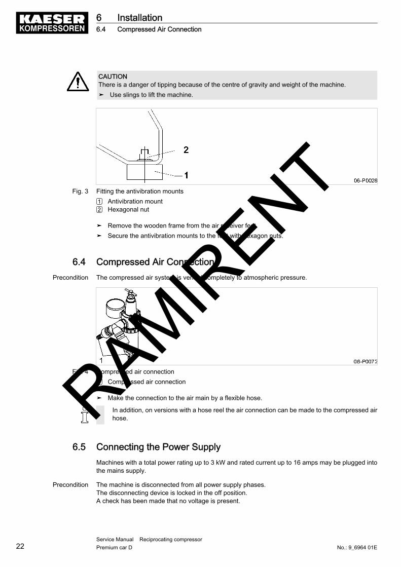
CAUTIONThere is a danger of tipping because of the centre of gravity and weight of the machine.➤ Use slings to lift the machine.
Fig. 3 Fitting the antivibration mounts1 Antivibration mount2 Hexagonal nut
➤ Remove the wooden frame from the air receiver feet.➤ Secure the antivibration mounts to the feet with hexagon nuts.
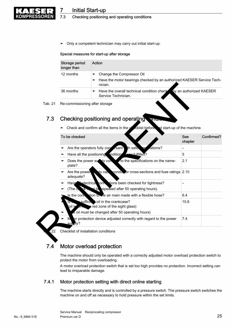
6.4 Compressed Air ConnectionPrecondition The compressed air system is vented completely to atmospheric pressure.
Fig. 4 Compressed air connection1 Compressed air connection
➤ Make the connection to the air main by a flexible hose.
In addition, on versions with a hose reel the air connection can be made to the compressed airhose.
6.5 Connecting the Power SupplyMachines with a total power rating up to 3 kW and rated current up to 16 amps may be plugged intothe mains supply.
Precondition The machine is disconnected from all power supply phases.The disconnecting device is locked in the off position.A check has been made that no voltage is present.
6 Installation6.4 Compressed Air Connection
22Service Manual Reciprocating compressor Premium car D No.: 9_6964 01E
RAMIRENT

1. Carry out safety measures as stipulated in relevant regulations (IEC 364, for example orDIN VDE 0100) and in national accident prevention regulations (BGV A3 in Germany). In addition,observe the regulations of the local electricity supplier.
2. Check the permitted disconnect time for the overload protection cut-out if a fault arises.3. Use wire conductor dimensions and fuse ratings in accordance with local regulations
(VDE 0100 parts 430 and 523 in Germany, for example).
DANGERDanger of fatal injury from electric shock!➤ Switch off and lock out the power supply disconnecting device and check that no voltage is
present.
4. Connect the machine to the power supply.
6 Installation6.5 Connecting the Power Supply
No.: 9_6964 01EService Manual Reciprocating compressor Premium car D 23
RAMIRENT

7 Initial Start-up7.1 Safety
Here you will find instructions for safe initial start-up of the machine.Warning instructions are located before a potentially dangerous task.
Basic safety instructions
1. Follow the instructions in chapter "Safety and Responsibility".2. Have the initial start-up carried out by authorized installation personnel only.3. Before switching on, make sure that:
■ no personnel are working on the machine,■ all panels are in place and secured.
Working on live components
1. Work on electrical equipment may only be carried out by authorized electricians.2. Switch off and lock out the power supply disconnecting device and check that no voltage is
present.
Working on pressure systems
1. Close shut-off valves or otherwise isolate the machine from the compressed air system to ensurethat no compressed air can flow back into the machine.
2. Vent all pressurized components and chambers completely.3. The pressure gauge on the machine must read 0 bar.
Working on the drive system
1. Switch off and lock out the power supply disconnecting device and check that no voltage ispresent.
2. Replace and secure all enclosure panels before starting the machine.
Further information See chapter 3.4.2 regarding authorized personnel.See chapter 3.5 regarding dangers and their avoidance.
7.2 Instructions to be observed before commissioning or recommission‐ingIncorrect or improper initial start-up can cause damage to the machine.
7 Initial Start-up7.1 Safety
24Service Manual Reciprocating compressor Premium car D No.: 9_6964 01E
RAMIRENT
➤ Only a competent technician may carry out initial start-up.
Special measures for start-up after storage
Storage periodlonger than
Action
12 months ➤ Change the Compressor Oil➤ Have the motor bearings checked by an authorized KAESER Service Tech‐
nician.
36 months ➤ Have the overall technical condition checked by an authorized KAESERService Technician.
Tab. 21 Re-commissioning after storage
7.3 Checking positioning and operating conditions➤ Check and confirm all the items in the checklist before first start-up of the machine.
To be checked Seechapter
Confirmed?
➤ Are the operators fully conversant with safety regulations? –
➤ Have all the positioning conditions been fulfilled? 5
➤ Does the power supply conform to the specifications on the name‐plate?
2.1
➤ Are the power supply cable conductor cross-sections and fuse ratingsadequate?
2.10
➤ Have all electrical connections been checked for tightness?➤ (The check must be repeated after 50 operating hours).
–
➤ Is the connection to the air main made with a flexible hose? 6.4
➤ Is there sufficient oil in the crankcase?(oil level in the red zone of the sight glass)
➤ (The oil must be changed after 50 operating hours)
10.6
➤ Motor protection device adjusted correctly with regard to the powersupply?
7.4
Tab. 22 Checklist of installation conditions
7.4 Motor overload protectionThe machine should only be operated with a correctly adjusted motor overload protection switch toprotect the motor from overloading.A motor overload protection switch that is set too high provides no protection. Incorrect setting canlead to irreparable damage.
7.4.1 Motor protection setting with direct online starting
The machine starts directly and is controlled by a pressure switch. The pressure switch switches themachine on and off as necessary to hold pressure within the set limits.
7 Initial Start-up7.3 Checking positioning and operating conditions
No.: 9_6964 01EService Manual Reciprocating compressor Premium car D 25
RAMIRENT

The motor overload protection switch setting can be 10 % higher than the rated motor currentto prevent it from being triggered by voltage fluctuations, temperature influences or componenttolerances.
1. Read the rated motor current from the nameplate and calculate the correct protection setting.2. Check the motor overload protection switch setting.3. Adjust the protection setting, if necessary.4. Switch on the compressor at the pressure switch.
The machine is shut down by the motor overload protection switch?➤ Allow the motor to cool down.➤ Switch the machine on again.
Further information See chapter 8.
7.5 Checking direction of rotationThe machine is designed for a clockwise phase sequence.Ideally, the direction of phase rotation should be measured with a phase sequence meter. Alterna‐tively, start the machine very briefly and observe the direction of rotation of the motor cooling fan.1. Check the direction of phase rotation with a phase sequence meter.2. If the direction is incorrect, reverse supply phases L1 and L2.
You have no phase sequence meter?➤ Switch the machine on and off again the moment the drive motor begins to turn.➤ Check the direction of rotation against the arrow on the fan cowl.➤ If the direction is incorrect, reverse L1 and L2.
7.6 Starting the machine for the first timePrecondition No personnel are working on the machine
➤ Switch on the mains isolating device and the pressure switch.The machine switches to LOAD and delivers compressed air.
➤ Keep an eye on the machine during the first few hours of operation to ensure that it isoperating correctly.
Carry (or have carried) out the following tasks after the first 50 operating hours:➤ Check that all electrical connections are tight.➤ Change the compressor oil.
7.7 Measuring the Air Receiver Filling TimeMeasuring the time the compressor takes to fill the air receiver when new can be useful in checkingthe machine's performance at a later date.
Precondition Machine at operating temperature.
1. Disconnect all air consumers.2. Switch on the power supply disconnecting device.
7 Initial Start-up7.5 Checking direction of rotation
26Service Manual Reciprocating compressor Premium car D No.: 9_6964 01E
RAMIRENT
3. Measure the air receiver filling time.4. Enter the filling time and machine model in the table.
Machine model Receiver filling time from 3–8 bar [min/s]
Tab. 23 Air receiver filling time
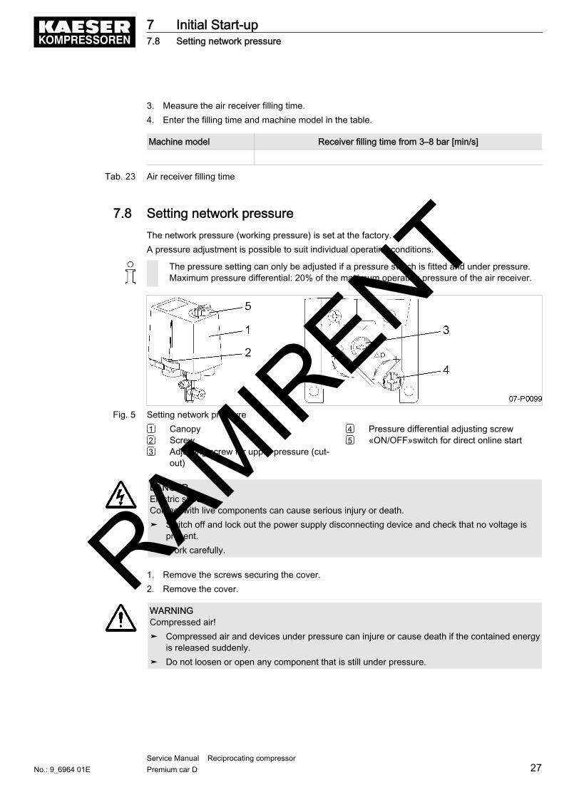
7.8 Setting network pressureThe network pressure (working pressure) is set at the factory.A pressure adjustment is possible to suit individual operating conditions.
The pressure setting can only be adjusted if a pressure switch is fitted and under pressure.Maximum pressure differential: 20% of the maximum operating pressure of the air receiver.
Fig. 5 Setting network pressure1 Canopy2 Screw3 Adjusting screw for upper pressure (cut-
out)
4 Pressure differential adjusting screw5 «ON/OFF»switch for direct online start
DANGERElectric shock!Contact with live components can cause serious injury or death.➤ Switch off and lock out the power supply disconnecting device and check that no voltage is
present.➤ Work carefully.
1. Remove the screws securing the cover.2. Remove the cover.
WARNINGCompressed air!➤ Compressed air and devices under pressure can injure or cause death if the contained energy
is released suddenly.➤ Do not loosen or open any component that is still under pressure.
7 Initial Start-up7.8 Setting network pressure
No.: 9_6964 01EService Manual Reciprocating compressor Premium car D 27
RAMIRENT

3. Adjust the pressure switch setting according to the table.
Adjusting the setting Function
Cut-out pressure is to be increased. ➤ Turn the adjusting screw 3 clockwise (direc‐tion: +).
Cut-out pressure is to be decreased. ➤ Turn the adjusting screw 3 anticlockwise (di‐rection: −).
The pressure differential between cut-in and cut-out pressure is to be increased.
➤ Turn the adjusting screw 4 clockwise (direc‐tion: +).
The pressure differential between cut-in and cut-out pressure is to be decreased.
➤ Turn the adjusting screw 4 anticlockwise (di‐rection: −).
Tab. 24 Changing the pressure switch setting
4. Replace the cover.
The motor starting frequency is to be reduced?➤ Increase the difference between cut-in and cut-out pressure.➤ Add a larger air receiver downstream to increase buffer capacity.
Further information The duty cycle of the machine is given in chapter 2.12.See table 11 for the machine starting frequency.
7.9 Setting the filter regulatorThe working pressure of a compressor fluctuates according to the limits set on the pressure switch.The filter regulator unit reduces this fluctuation to the required pressure and holds it constant.
Precondition The machine is isolated from the air consumers.
Fig. 6 Setting the filter regulator1 Adjusting screw2 Locknut
3 Pressure gauge (working pressure)4 Compressed air outlet
1. Start the machine and run it up to cut-out pressure.2. To relieve the filter regulator, turn the adjusting screw anticlockwise until no more resistance is
felt.3. Turn the adjusting screw clockwise until the pressure gauge reads the required working pressure.4. Tighten the locknut to fix the adjusting screw in position.
7 Initial Start-up7.9 Setting the filter regulator
28Service Manual Reciprocating compressor Premium car D No.: 9_6964 01E
RAMIRENT
8 Operation8.1 Switching on and off
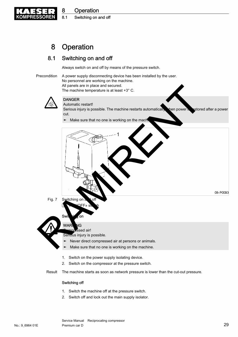
Always switch on and off by means of the pressure switch.
Precondition A power supply disconnecting device has been installed by the user.No personnel are working on the machine.All panels are in place and secured.The machine temperature is at least +3° C.
DANGERAutomatic restart!Serious injury is possible. The machine restarts automatically when power is restored after a powercut.➤ Make sure that no one is working on the machine.
Fig. 7 Switching on and off1 «ON/OFF» switch
Switching on
WARNINGCompressed air!Serious injury is possible.➤ Never direct compressed air at persons or animals.➤ Make sure that no one is working on the machine.
1. Switch on the power supply isolating device.2. Switch on the compressor at the pressure switch.
Result The machine starts as soon as network pressure is lower than the cut-out pressure.
Switching off
1. Switch the machine off at the pressure switch.2. Switch off and lock out the main supply isolator.
8 Operation8.1 Switching on and off
No.: 9_6964 01EService Manual Reciprocating compressor Premium car D 29
RAMIRENT
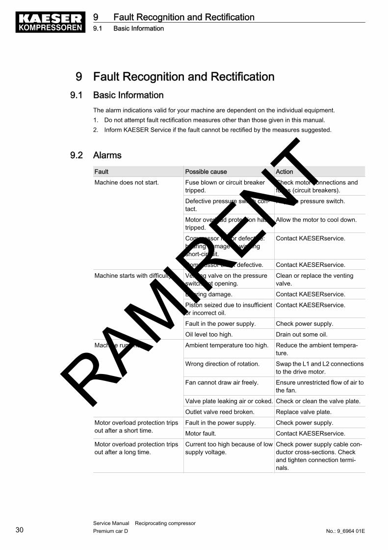
9 Fault Recognition and Rectification9.1 Basic Information
The alarm indications valid for your machine are dependent on the individual equipment.1. Do not attempt fault rectification measures other than those given in this manual.2. Inform KAESER Service if the fault cannot be rectified by the measures suggested.
9.2 AlarmsFault Possible cause Action
Machine does not start. Fuse blown or circuit breakertripped.
Check motor connections andfuses (circuit breakers).
Defective pressure switch con‐tact.
Replace pressure switch.
Motor overload protection hastripped.
Allow the motor to cool down.
Compressor motor defective:bearing damage or windingshort-circuit.
Contact KAESERservice.
Compressor block defective. Contact KAESERservice.
Machine starts with difficulty. Venting valve on the pressureswitch not opening.
Clean or replace the ventingvalve.
Bearing damage. Contact KAESERservice.
Piston seized due to insufficientor incorrect oil.
Contact KAESERservice.
Fault in the power supply. Check power supply.
Oil level too high. Drain out some oil.
Machine runs hot. Ambient temperature too high. Reduce the ambient tempera‐ture.
Wrong direction of rotation. Swap the L1 and L2 connectionsto the drive motor.
Fan cannot draw air freely. Ensure unrestricted flow of air tothe fan.
Valve plate leaking air or coked. Check or clean the valve plate.
Outlet valve reed broken. Replace valve plate.
Motor overload protection tripsout after a short time.
Fault in the power supply. Check power supply.
Motor fault. Contact KAESERservice.
Motor overload protection tripsout after a long time.
Current too high because of lowsupply voltage.
Check power supply cable con‐ductor cross-sections. Checkand tighten connection termi‐nals.
9 Fault Recognition and Rectification9.1 Basic Information
30Service Manual Reciprocating compressor Premium car D No.: 9_6964 01E
RAMIRENT

Fault Possible cause Action
The machine runs continuouslybut maximum pressure is notreached.
Air filter clogged. Clean or change the air filter.
Valve plate leaking air or coked. Check or clean the valve plate.
Outlet valve reed broken. Replace valve plate.
Machine leaks air. Seal leak or replace leaking part.
Leakage from an air consumerconnected to the air system.
Check possible leakage points.
The air demand is greater thanthe machine's air delivery ca‐pacity.
Use a larger machine.
Machine cuts in and out too of‐ten.
Air receiver filled with conden‐sate.
Drain condensate.
The machine switches off and airescapes from the venting valve.
Check valve is defective. Replace the check valve.
The venting valve loses air whilethe machine is running.
The venting valve is not closing. Clean or replace the ventingvalve.
The pressure switch does notvent after switching off.
Venting valve dirty. Clean or replace the ventingvalve.
Air leaks from the pressureswitch while the machine is run‐ning.
Defective switch diaphragm. Replace the pressure switch.
The venting valve is not closing. Clean or replace the ventingvalve.
Whistling sound from the cylin‐der head.
Cylinder head fixing screwsloose. Gasket defective.
Tighten the cylinder head fixingscrews. Replace gasket.
The pressure relief valve blowsoff before the cut-out pressure isreached.
Pressure switch incorrectly set. Check pressure switch setting.
Valve spring defective. Replace the pressure reliefvalve.
Dirt or foreign bodies on thevalve seat.
Let the pressure relief valve blowoff briefly.
Pressure relief valve on the aircooler blows off prematurely.
Cooler clogged. Cooler pipecoked.
Clean the radiator.
Machine uses too much oil. Viscosity too low. Fill with oil specified in the ser‐vice manual.
Crankcase venting defective. Clean or renew the crankcasevent.
Piston rings worn or broken. Contact KAESERservice.
Piston rings already worn ordamaged after only a short op‐erating period.
Dirty oil. Fit finer air inlet filter.
Tab. 25 Faults and remedies
9 Fault Recognition and Rectification9.2 Alarms
No.: 9_6964 01EService Manual Reciprocating compressor Premium car D 31
RAMIRENT
10 Maintenance10.1 Safety
Follow the instructions below to ensure safe machine maintenance.Warning instructions are located before a potentially dangerous task.
Basic safety instructions
1. Follow the instructions in chapter "Safety and Responsibility".2. Maintenance work may only be carried out by authorized personnel.3. Before switching on, make sure that:
■ no personnel are working on the machine,■ all panels are in place and secured.
Working on live components
1. Work on electrical equipment may only be carried out by authorized electricians.2. Switch off and lock out the power supply disconnecting (isolating) device and check that no volt‐
age is present.
Working on pressure systems
1. Close shut-off valves or otherwise isolate the machine from the compressed air system to ensurethat no compressed air can flow back into the machine.
2. Vent all pressurized components and chambers completely.3. The pressure gauge on the machine must read 0 bar.
Working on the drive system
1. Switch off and lock out the power supply disconnecting (isolating) device and check that no volt‐age is present.
2. Replace and secure all enclosure panels before starting the machine.
Further information See chapter 3.4.2 regarding authorized personnel.See chapter 3.5 regarding dangers and their avoidance.
10.2 Maintenance Schedule
10.2.1 Logging maintenance work
The maintenance intervals given are those recommended for average operating conditions.➤ Adjust the maintenance intervals with regard to local installation and operating conditions.
➤ Keep a log of all maintenance and service work.This enables the frequency of individual maintenance tasks and deviations from our recommen‐dations to be determined.
Further information A prepared list is provided in chapter 10.16.
10 Maintenance10.1 Safety
32Service Manual Reciprocating compressor Premium car D No.: 9_6964 01E
RAMIRENT

10.2.2 Regular maintenance tasks
➤ When operating conditions are unfavourable (e.g. dusty atmosphere) or when the equipment isin constant use, maintenance tasks must be carried out more frequently (shorter intervals).
Interval Maintenance task See chapter
Daily or every 24 operat‐ing hours
Check the oil level. 10.6
Drain off condensate from the receiver. 10.10
Drain condensate from the filter regulator. 10.14
Annually Carry out air filter maintenance 10.4
Maintain the check valve 10.12
Check that all electrical connections are tight. –
Check the pressure relief valve 10.9
Variable,see table 27
Change the oil. 10.8
h = operating hours
Tab. 26 Regular maintenance tasks
10.2.3 Oil change interval
Duty cycles and ambient conditions are important criteria for the number and length of the oil changeintervals.
Advice can be obtained from KAESER Service on determining suitable changing intervals.
➤ Check operating conditions and adjust intervals as necessary; log the results in table 27 for futurereference.
Maximum permissible oil change interval[operating hours/years]
Compressor oil Favourable operating conditions* My operating conditions
VDL 150 1000/1
FGP 1000/2
* Cool to moderate ambient temperatures, low humidity, low to average duty cycle.
Tab. 27 Oil change intervals
10.2.4 Regular service tasks
➤ Only an authorised KAESER Service Technician should carry out service work.➤ When operating conditions are unfavourable (e.g. dusty or humid atmosphere) or when the
equipment is in constant use, have the service work carried out more frequently (shorter intervals).
Interval Service task
Every 2 years at least Change the air filter element
Up to 3000 h Have cylinder head and valves checked.
h = operating hours
10 Maintenance10.2 Maintenance Schedule
No.: 9_6964 01EService Manual Reciprocating compressor Premium car D 33
RAMIRENT

Interval Service task
Up to 12,000 h Have the machine generally overhauled.
up to 12,000 h, every threeyears at the latest
Have motor bearings checked.
h = operating hours
Tab. 28 Regular service tasks
10.3 Air cooler maintenanceClogging causes overheating and machine damage.
Regular cleaning ensures reliable cooling of the machine and the compressed air. The frequency ismainly dependent on local operating conditions.
Material BrushVacuum cleanerFace mask (as required)
Precondition The supply disconnecting device is switched off,the device is locked off,a check has been made that no voltage is present.The machine has cooled down.
Fig. 8 Cleaning the air cooler1 Compressed air cooler2 Brush
10.3.1 Cleaning the air cooler
Do not use sharp objects to clean the air cooler. It could cause damage.Avoid creating clouds of dust.➤ Dry brush the air cooler and safety screen using a vacuum cleaner to suck up the dirt.
The air cooler can't be cleaned thoroughly?➤ Have stubborn clogging removed by an authorized KAESER Service Technician.
10 Maintenance10.3 Air cooler maintenance
34Service Manual Reciprocating compressor Premium car D No.: 9_6964 01E
RAMIRENT

10.4 Air filter maintenanceThe air filter contains a filter element that can be washed but not removed.
Material Compressed air for blowing outSolvent cleanerCleaning clothsSpares as required
Precondition The supply disconnecting device is switched off,the device is locked off,a check has been made that no voltage is present.The machine has cooled down.
Fig. 9 Air filter maintenance1 Air filter2 Inlet air opening3 Filter element
4 Retaining clip5 Cover
1. Unscrew the air filter.2. Release the retaining clip and take off the cover.3. Blow out the cover and filter element with dry compressed air (< 5 bar).4. Clean the housing and sealing faces.5. Wet the filter element lightly with oil after cleaning.
If the filter element is heavily clogged, clean with a solvent-based fluid or steam blaster.Observe safety regulations.Replace the air filter if it has already been cleaned a number of times.
6. Position the cover over the element and close the retaining clips.7. Mount the air filter again.
The filter air inlet must face downwards.
8. Switch on the power supply disconnecting device.
10 Maintenance10.4 Air filter maintenance
No.: 9_6964 01EService Manual Reciprocating compressor Premium car D 35
RAMIRENT

10.5 Drive Motor MaintenanceThe drive motor bearings are permanently greased and need no re-greasing.➤ Have the motor bearings checked during service.
10.6 Checking the Oil LevelThe oil level can be read off on the oil sight glass.
Precondition The machine is shut down.
Fig. 10 Checking the Oil Level1 Oil filler and crankcase vent2 Oil sight glass
➤ Read off the oil level daily and before each start-up.
Result Top up when the compressor oil level falls to the minimum mark.
10.7 Topping up the compressor oilMaterial Compressor oil
Precondition The supply disconnecting device is switched off,the device is locked off,a check has been made that no voltage is present.The machine has cooled down.
CAUTIONThe machine can be damaged by unsuitable oil.➤ Never mix different types of oil.➤ Never top up with a different type of oil to that already used in the machine.
The type of compressor oil used is listed in table 12.1. Remove the crankcase vent from the oil filler.2. Top up to bring the oil to the correct level.
10 Maintenance10.5 Drive Motor Maintenance
36Service Manual Reciprocating compressor Premium car D No.: 9_6964 01E
RAMIRENT

3. Replace the crankcase vent.4. Start the machine and check the oil level again after about 2 minutes, topping up again, if nec‐
essary.5. Switch off the machine and check visually for leaks.
10.8 Changing the Compressor OilThe initial charge of oil should be changed as specified in the table 26.Drain the oil completely from the compressor block.
Change the oil immediately if it becomes milky white.This means there is condensate in it.Contact KAESER Service if condensate is detected in the oil.
Material Compressor oilOil receptacle
Precondition Machine at operating temperature.The power supply disconnecting device is switched off.The disconnecting device is locked in the off position.A check has been made that no voltage is present.
CAUTIONDanger of burning from hot components and scalding from escaping oil.➤ Wear long-sleeved clothing and gloves.
Fig. 11 Changing the compressor oil1 Oil filler port2 Oil sight glass3 Oil drain plug
Draining the oil
1. Remove the crankcase vent from the oil filler.2. Position the oil receptacle.3. Remove the drain plug and allow oil to drain into the receptacle.4. Replace the drain plug after making sure the gasket is not damaged.
10 Maintenance10.8 Changing the Compressor Oil
No.: 9_6964 01EService Manual Reciprocating compressor Premium car D 37
RAMIRENT
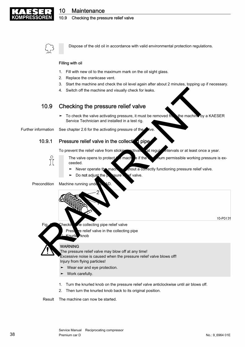
Dispose of the old oil in accordance with valid environmental protection regulations.
Filling with oil
1. Fill with new oil to the maximum mark on the oil sight glass.2. Replace the crankcase vent.3. Start the machine and check the oil level again after about 2 minutes, topping up if necessary.4. Switch off the machine and visually check for leaks.
10.9 Checking the pressure relief valve➤ To check the valve activating pressure, it must be removed from the machine by a KAESER
Service Technician and installed in a test rig.
Further information See chapter 2.6 for the activating pressure of the valve.
10.9.1 Pressure relief valve in the collecting pipe
To prevent the relief valve from sticking, activate it at regular intervals or at least once a year.
The valve opens to protect the machine if the maximum permissible working pressure is ex‐ceeded.➤ Never operate the machine without a correctly functioning pressure relief valve.➤ Do not adjust the pressure relief valve.
Precondition Machine running under LOAD.
Fig. 12 Checking the collecting pipe relief valve1 Pressure relief valve in the collecting pipe2 Knurled knob
WARNINGThe pressure relief valve may blow off at any time!Excessive noise is caused when the pressure relief valve blows off!Injury from flying particles!➤ Wear ear and eye protection.➤ Work carefully.
1. Turn the knurled knob on the pressure relief valve anticlockwise until air blows off.2. Then turn the knurled knob back to its original position.
Result The machine can now be started.
10 Maintenance10.9 Checking the pressure relief valve
38Service Manual Reciprocating compressor Premium car D No.: 9_6964 01E
RAMIRENT

Pressure relief valve does not blow off?➤ Have the defective relief valve replaced by KAESER Service.
10.9.2 Air receiver pressure relief valve
To prevent the relief valve from sticking, activate it at regular intervals or at least once a year.
The valve opens to protect the machine if the maximum permissible working pressure is ex‐ceeded.➤ Never operate the machine without a correctly functioning pressure relief valve.➤ Do not adjust the pressure relief valve.
Precondition The machine is switched off under LOAD,the power supply isolating device is locked off,a check has been made that no voltage is present.
Fig. 13 Checking pressure relief valve on the air receiver1 Pressure relief valve2 Knurled knob
WARNINGThe pressure relief valve may blow off at any time!Excessive noise is caused when the pressure relief valve blows off!Injury from flying particles!➤ Wear ear and eye protection.➤ Work carefully.
1. Close the user's shut-off valve between the machine and the air distribution network.2. Turn the knurled knob on the pressure relief valve anticlockwise until air blows off.3. Then turn the knurled knob back to its original position.4. Open the user's shut-off valve between the machine and the air distribution network.
Result The machine can now be started.
Pressure relief valve does not blow off?➤ Have the defective relief valve replaced by KAESER Service.
10.10 Air ReceiverPressure vessels must be inspected at regular intervals in accordance with legal requirements.
10 Maintenance10.10 Air Receiver
No.: 9_6964 01EService Manual Reciprocating compressor Premium car D 39
RAMIRENT

➤ Observe relevant national regulations.➤ Drain the condensate out daily.
10.11 Venting the machine (de-pressurising)After being switched off, the machine is still under pressure from the air network up to the check valve.
The machine must be isolated from the air network and completely vented before undertakingany maintenance or service work on the pressure system.
Precondition The supply disconnecting device is switched off,the device is locked off,the absence of voltage has been verified.The machine has cooled down.
Fig. 14 Venting the machine 1 Condensate drain tap
DANGERCompressed air!Compressed air and devices under pressure can injure or cause death if the contained energy isreleased suddenly.➤ Isolate the compressor from the air system.
1. Open the condensate drain slowly and release pressure completely.2. Check that the air receiver pressure gauge reads 0 bar.
After automatic venting the pressure gauge does not read zero?Shut-off valve still open.➤ Defective condensate drain.➤ If manual venting does not bring the oil separator tank pressure gauge to zero: Contact the
authorised KAESER Service.
10 Maintenance10.11 Venting the machine (de-pressurising)
40Service Manual Reciprocating compressor Premium car D No.: 9_6964 01E
RAMIRENT

10.12 Maintaining the check valveThe check valve is installed in the air receiver inlet port. It prevents the compressed air from flowingback from the air receiver to the compressor block.
Material Compressed air for blowing outCleaning clothsSpares as required
Precondition The supply disconnecting device is switched off,the device is locked off,the absence of voltage has been verified.The machine is completely depressurised (pressure gauge reads 0 bar).The machine has cooled down.
Fig. 15 Cleaning the check valve1 Enclosure2 Screw plug3 Valve cone
4 Valve seat5 Spring6 O-ring
CAUTIONDanger of burns from hot components!➤ Wear long-sleeved clothing and gloves.➤ Work carefully.
1. Remove the plug.2. Clean the valve cone and seat.
The complete valve must be replaced if the valve seat is badly worn or damaged.
3. Insert the valve cone and spring in the housing.4. Reseal the housing with the plug and O-ring.
10.13 Maintenance of the pressure switch unloading valveThe unloading valve must be cleaned in the following circumstances:■ Machine starts with difficulty.■ The machine does not vent after switching off.
10 Maintenance10.12 Maintaining the check valve
No.: 9_6964 01EService Manual Reciprocating compressor Premium car D 41
RAMIRENT

Material Compressed air for blowing outCleaning clothsSpares as required
Precondition The supply disconnecting device is switched off,the device is locked off,the absence of voltage has been verified.The machine is completely depressurised (pressure gauge reads 0 bar).The machine has cooled down.
Fig. 16 Maintenance of the pressure switch unloading valve1 Unloading valve2 Screw3 Screw plug4 Ball
5 Spring6 Gasket7 Valve cone8 Screw connection
Open the valve carefully.
1. Remove the fitting from the valve.2. Loosen the securing screws and take off the unloading valve.3. Remove the screw plug and take out the individual parts.4. Extract the valve cone and clean it together with the other parts.5. After reassembly insert the valve and tighten down with the screw.
10.14 Cleaning the filter regulatorEmpty accumulating condensate at regular intervals, at least once a day.
Material Compressed air for blowing outCleaning ragsSpare parts as required
Precondition The power supply disconnecting device is switched off.The disconnecting device is locked in the off position.A check has been made that no voltage is present.Machine is fully vented (no pressure).
➤ Drain condensate.
10 Maintenance10.14 Cleaning the filter regulator
42Service Manual Reciprocating compressor Premium car D No.: 9_6964 01E
RAMIRENT

➤ Collect the condensate in a suitable container and dispose of in accordance with environ‐mental regulations.
Cleaning the filter element
Fig. 17 Cleaning the Filter Regulator1 Condensate outlet2 Housing
3 Label (cleaning agent)4 Filter element
1. Unscrew and clean the housing and filter element.
Refer to the label on the housing for selection of the cleaning agent.
2. Blow out the housing with compressed air (<5 bar).3. Reassemble the parts and make sure they sit correctly.
10.15 Cylinder Head and ValvesThe condition of the valves can be assessed by measuring the receiver charging time and comparingthis with the charging time when the machine was new.
10.15.1 Checking the cylinder head and valves
Precondition Machine at operating temperature.
➤ Start the machine and measure the receiver charging time.
Result If there is a significant difference in the filling time to when the machine was new, have KAESERService check or replace the valves.
Further information See chapter 7.7 for receiver filling time measurement.
10 Maintenance10.15 Cylinder Head and Valves
No.: 9_6964 01EService Manual Reciprocating compressor Premium car D 43
RAMIRENT

10.16 Document maintenance and service work.Machine number:➤ Enter maintenance and service work carried out in the list.
Date Maintenance task carried out Operating hours Signature
Tab. 29 Logged maintenance tasks
10 Maintenance10.16 Document maintenance and service work.
44Service Manual Reciprocating compressor Premium car D No.: 9_6964 01E
RAMIRENT
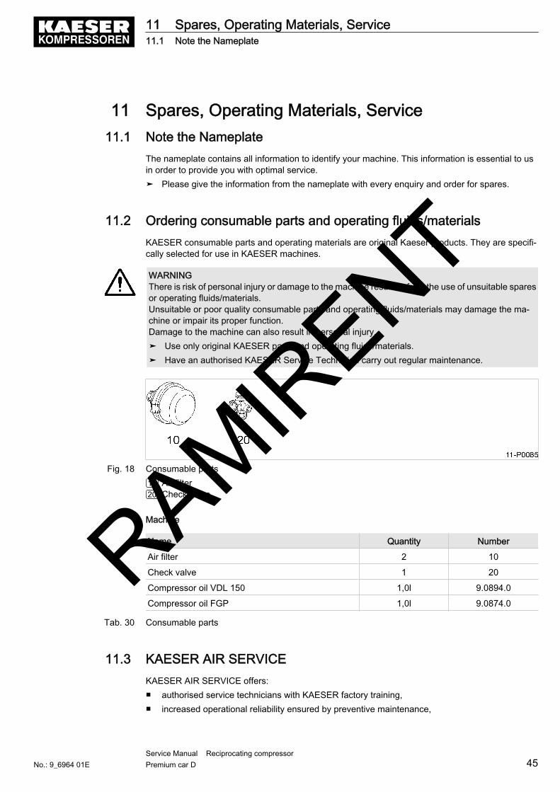
11 Spares, Operating Materials, Service11.1 Note the Nameplate
The nameplate contains all information to identify your machine. This information is essential to usin order to provide you with optimal service.➤ Please give the information from the nameplate with every enquiry and order for spares.
11.2 Ordering consumable parts and operating fluids/materialsKAESER consumable parts and operating materials are original Kaeser products. They are specifi‐cally selected for use in KAESER machines.
WARNINGThere is risk of personal injury or damage to the machine resulting from the use of unsuitable sparesor operating fluids/materials.Unsuitable or poor quality consumable parts and operating fluids/materials may damage the ma‐chine or impair its proper function.Damage to the machine can also result in personal injury.➤ Use only original KAESER parts and operating fluids/materials.➤ Have an authorised KAESER Service Technician carry out regular maintenance.
Fig. 18 Consumable parts10 Air filter20 Check valve
Machine
Name Quantity Number
Air filter 2 10
Check valve 1 20
Compressor oil VDL 150 1,0l 9.0894.0
Compressor oil FGP 1,0l 9.0874.0
Tab. 30 Consumable parts
11.3 KAESER AIR SERVICEKAESER AIR SERVICE offers:■ authorised service technicians with KAESER factory training,■ increased operational reliability ensured by preventive maintenance,
11 Spares, Operating Materials, Service11.1 Note the Nameplate
No.: 9_6964 01EService Manual Reciprocating compressor Premium car D 45
RAMIRENT

■ energy savings achieved by avoidance of pressure losses,■ optimum conditions for operation of the compressed air system,■ the security of genuine KAESER spare parts,■ increased legal certainty as all regulations are kept to.
➤ Why not sign a KAESER AIR SERVICE maintenance agreement!
Result Your advantage:lower costs and higher compressed air availability.
11.4 Service AddressesAddresses of KAESER agents are given at the end of this manual.
11.5 Spare Parts for Service and Repair➤ Make sure that any service or repair tasks not described in this manual are carried out by
an authorized KAESER Service Technician.
11 Spares, Operating Materials, Service11.4 Service Addresses
46Service Manual Reciprocating compressor Premium car D No.: 9_6964 01E
RAMIRENT

12 Decommissioning, Storage and Transport12.1 De-commissioning
De-commissioning is necessary, for example, under the following circumstances:■ the machine is temporarily not needed,■ the machine is to be moved to another location,■ the machine is to be scrapped.
Temporary de-commissioning
Precondition The machine can be started at regular intervals.
➤ Run the machine once a week under load for at least 30 minutes to ensure corrosion protection.
Long-term de-commissioning
Precondition The machine must have run for at least 30 minutes before before long-term de-commissioning.The mains disconnecting device is switched off.The disconnecting device is locked in the off position.A check has been made that no voltage is present.Machine fully vented (no pressure).
1. Allow the machine to cool down completely.2. Spray the valves and cylinder bore with Shell Ensis 20 preserving oil.
The preserving oil does not need to be removed when re-commissioning.
3. Drain condensate.4. Disconnect all air and electrical connections.5. Spray all contacts and terminals with a preservative (e.g. Rivalto, W.S.X.).
12.2 PackingA wooden crate is required for overland transport to protect the machine from mechanical damage.Consult KAESER Service for advice on packing for sea or air transport.
Material DesiccantPlastic sheetingWooden transport crate
Precondition The machine is decommissioned.Machine is dry and cooled down.
1. Wrap the machine in plastic sheeting.2. Place sufficient desiccant (e.g. silica gel) inside the plastic sheeting.
12 Decommissioning, Storage and Transport12.1 De-commissioning
No.: 9_6964 01EService Manual Reciprocating compressor Premium car D 47
RAMIRENT

12.3 StorageMoisture can lead to corrosion, particularly on the surfaces of the compressor block.Frozen moisture can damage components, diaphragms, valves and gaskets.
Advice can be obtained from KAESER on storage and commissioning.
CAUTIONMoisture and frost can damage the machine.➤ Prevent ingress of moisture and formation of condensation.➤ Maintain a storage temperature of >0 °C.
➤ Store the machine in a dry, frost-proof room.
12.4 Transporting
12.4.1 Safety
Avoid damaging the machine.➤ Transport only with the enclosure fully closed.
12.5 DisposalWhen disposing of a machine, drain out all liquids and remove dirty filters.
Precondition The machine is decommissioned.
1. Completely drain the oil from the machine.2. Remove old filters.3. Hand the machine over to an authorized disposal expert.
➤ Components contaminated with oil must be disposed of in accordance with local environ‐ment protection regulations.
12 Decommissioning, Storage and Transport12.3 Storage
48Service Manual Reciprocating compressor Premium car D No.: 9_6964 01E
RAMIRENT

13 Annex13.1 Dimensional Drawing
13 Annex13.1 Dimensional Drawing
No.: 9_6964 01EService Manual Reciprocating compressor Premium car D 49
RAMIRENT

13 Annex13.1 Dimensional Drawing
50Service Manual Reciprocating compressor Premium car D No.: 9_6964 01E
RAMIRENT

13.2 Electrical Diagram
13 Annex13.2 Electrical Diagram
No.: 9_6964 01EService Manual Reciprocating compressor Premium car D 51
RAMIRENT

13 Annex13.2 Electrical Diagram
52Service Manual Reciprocating compressor Premium car D No.: 9_6964 01E
RAMIRENT