no. 700 taper attachment f= - vintagemachinery.orgvintagemachinery.org/pubs/51/3456.pdf · no. 700...
TRANSCRIPT
INSTRUCTIONS AND PARTS PRICE LIST FOR
No. 700 TAPER ATTACHMENT
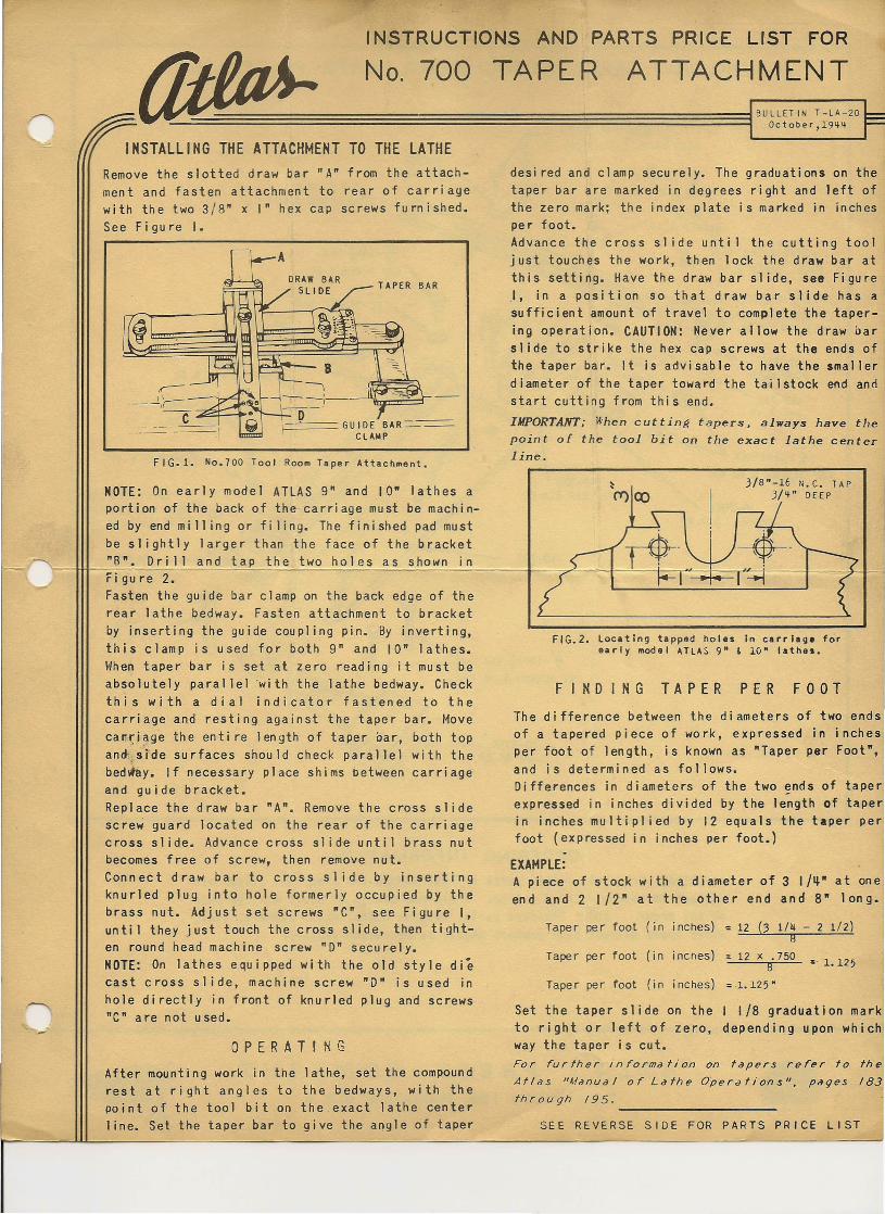
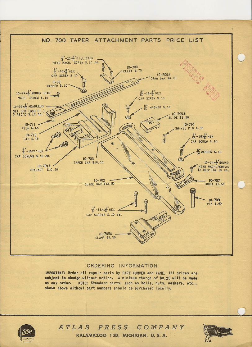
NOTE: On early model ATLAS 9" and 10· lathes aportion of the back of the carriage must be machin-ed by end mi II ing or fi ling. The finished pad mustbe slightly larger than the face of the bracket"8". Drill and tap the two holes as shown in'--------4Figure 2.Fasten the guide bar clamp on the back edge of therear lathe bedway. Fasten attachment to bracketby inserting the guide coupling pin. By inverting,this clamp is used for both g" and 10" lathes.When taper bar is set at zero reading it must beabsolutely parallel wi th the lathe bedway. Checkthis with a dial indicator fastened to thecarriage and resting against the taper bar. Moveca~~i~ge the enti re length of taper oar, both topan~ srde surfaces should check parallel with thebedvhly. If necessary place shims between carriageand guide bracket.Replace the draw bar "A". Remove the cross slidescrew guard located on the rear of the carriagecross sl ide. Advance cross sl ide unti 1 brass nutbecomes free of screw, then remove nut.Connect draw bar to cross slide by insertingknurled plug into hole formerly occupied by thebrass nut. Adjust set screws "CO, see Figure I,unti I they just touch the cross slide, then tight-en round head machine screw "D" securely.NOTE: On lathes equipped with the old style diecast cross slide, machine screw "0" is used inhole directly in front of knurled plug and screws"C" are not used.
INSTALLING THE ATTACHMENT TO THE LATHEIBULLETIN T-LA-20f=
October,19~~
desi red and clamp securely. The graduations on thetaper bar are marked in degrees right and left ofthe zero mark; the index plate is marked in inchesper foot.Advance the cross sl ide unti 1 the cutting tooljust touches the work, then lock the draw bar atthis setting. Have the draw bar sl ide, see FigureI, in a position so that draw bar slide has asufficient amount of travel to complete the taper-ing operation. CAUTION: Never allow the draw oarslide to strike the hex cap screws at the ends ofthe taper bar. It is advisable to have the smallerdiameter of the taper toward the tailstock end andstart cutting from this end.IMPORTANT; lI'hen cutting tapers, always have thepoint of the tool bit on the exact lathe centerline.
Remove the slotted draw bar "A" from the attach-ment and fasten attachment to rear of carriagewith the two 3/8" x I" hex cap screws furnished.See Figure I.
F IG.!. No.700 Tool Room Taper Attachment.
OPERATINGAfter mounting work in the lathe, set the compoundrest at right angles to the bedways, with thepoint of the tool bit on the exact lathe centerline. Set the taper bar to give the angle of taper
3/8"-16 N. C. TAP3/'1" DEEP
FIG.2. locating tapped holes In carriage forearly model HlAS 9" & 10" lathes.
FINDING TAPER PER FOOTThe difference between the diameters of two endsof a tapered piece of work, expressed in inchesper foot of length, is known as "Taper per Foot",and is determined as follows.Differences in diameters of the two ~nds of tape~expressed in inches divided by the length of taper.in inches multiplied by 12 equals the taper perfoot (expressed in inches per foot.)
EXAMPLE:A piece of stock with a diameter of 3 I/~" at oneen d and 2 I/2" a t the 0 the r end and 8" 1on g•
(3 l/ij - 2 1/2)8
Taper per foot (in inches) ~ 12 x .750~~~8~~ s· 1.125
Taper per foot (in inches) ':12
Taper per foot (in inches) ~.1.125·
Set the taper slide on the I 1/8 graduation markto right or left of zero, depending upon whichway the taper is cut.For further information on tapers refer to the
Atlas "Manual or Lathe Operations". pages 183
through 195. ----------------SEE REVERSE SIDE FOR PARTS PRICE LIST
NO. 700 TAPER ATTACHMENT PARTS PRICE LIST
!"-20xi"FILLISTERHEAD MACH. SCREW $.10 eal\
10-708.l"-16X2."HEX ~CLEAT $.15
cZp- SCR~'WS.10) - ~ - IO-706A"'---DRAW BAR S~.OO
9-93 ~ -Y~~~
'WASHERS. 10 ~
10-2~Xr ROUND HEAD---i 0
MACH. SCREW $.10
10-32XfHEAOLESS ---j~
SET SCR.(DOG PT.)3 REQ'D $.10 ea.~.~~
10-711PLUG $.~5
10-703TAPER BAR sra.oo
lo-705ACLAMP $ij.50
ORDERING INFORMATIONIMPORTAMT~ Order all repair parts by PART NUMBER and NAME. All prices aresubject to cha~ge without notice. A minimum charge of $0.25 will be madeon any order" NOTE: Standard parts, such as bolts, nuts, washers, etc.,shown above without part numbers should be purchased locally.
'.-----.----
ATLAS PRESS COMPANYKALAMAZOO 13D, MICHIGAN, U. S. A.